

Polaris Sportsman 400, Sportsman 500, Sportsman 500 H.O., SPORTSMAN 500 DUSE Service Manual
Page 1

CHAPTER INDEX
CHAPTER 1 GENERAL
CHAPTER 2 MAINTENANCE
CHAPTER 3 ENGINE
CHAPTER 4 FUEL SYSTEM/CARBURETION
CHAPTER 5 BODY / SUSPENSION
CHAPTER 6 PVT SYSTEM
CHAPTER 7 FINAL DRIVE
CHAPTER 8 TRANSMISSION
CHAPTER 9 BRAKES
CHAPTER 10 ELECTRICAL
Page 2

CHAPTER 1
GENERAL INFORMA
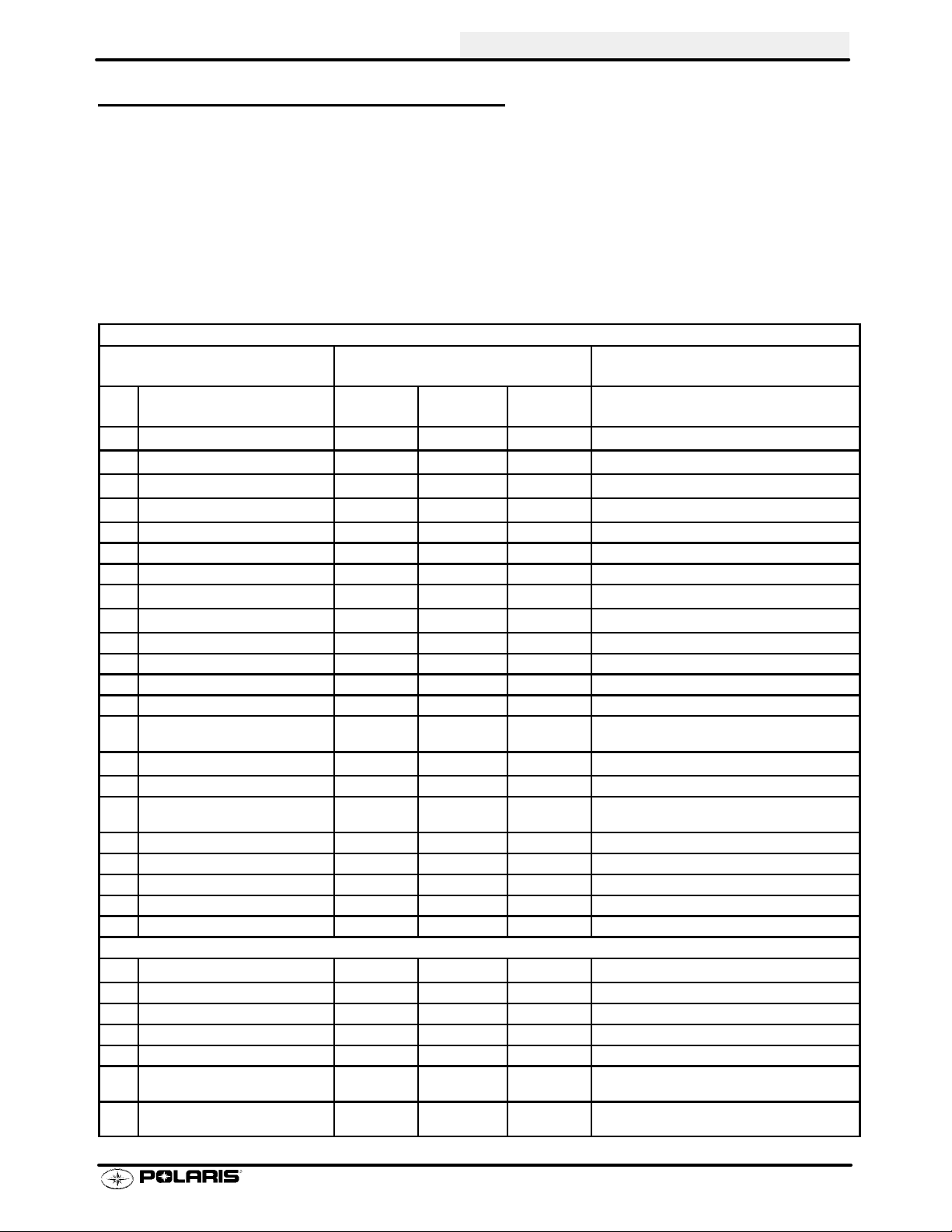
Model Identification 1.1...........................
Serial Number Location 1.1.......................
Replacement Keys 1.2............................
Model Color Identification 1.3-1.7......................
Machine Dimensions 1.8-1.10..........................
Specifications - Sportsman 400 1.11-1.12.................
Specifications - Sportsman 500 DUSE 1.13-1.14..........
Specifications - Sportsman 500 H.O. 1.15-1.16............
Publication Numbers 1.17..........................
Paint Codes 1.17.................................
Standard Torque Specifications 1.18................
Torque Conversion Table 1.19-1.20......................
Decimal Equivalent Chart 1.21......................
Conversion Table 1.22.............................
Tap Drill Charts 1.23...............................
Glossary of Terms 1.24-1.25............................
TION
1
Page 3
GENERAL INFORMATION
MODEL IDENTIFICATION
The machine model number must be used with any correspondence regarding warranty or service.
Machine Model Number Identification
A01CH50AA
Emissions &
Year Designation
Basic Chassis
Designation Engine Designation
Model Option
ENGINE DESIGNATION NUMBERS
42 EH42PLE05 Single, L/C, SOHC 4 Stroke, Electric Start............
50 EH50PLE09/13 Single, L/C, SOHC 4 Stroke, Electric Start..........
VIN IDENTIFICATION
World Mfg. ID
1 2 3 4 5 6 7 8 9 10 11 12 13 14 15 16 17
4XACH
Body Style
Vehicle Descriptor
50A*1P0 00000
Engine
Powertrain
Emissions
Check Digit
Model
Year
Plant No.
Vehicle Identifier
Individual Serial No.
* This could be either
a number or a letter
ENGINE SERIAL NUMBER LOCATION
Whenever corresponding about an engine, be sure to refer to the engine model number and serial number. This
information can be found on the sticker applied to the recoil housing on the right side of engine.(A) Anadditional
number is stamped on the center top of crankcase beneath the cylinder coolant elbow.
MACHINE MODEL NUMBER AND SERIAL NUMBER LOCATION
Themachinemodelnumber andserialnumberare
important for vehicle identification. The machine
serial number is stamped on the lower left side of
the frame tube.(B)
A
TRANSMISSION I.D. NUMBER
LOCA
The transmission I.D. number is located
on top of the transmission snorkel, right
side of machine.
TION
Front
B
1.1
Page 4
GENERAL INFORMATION
REPLACEMENT KEYS
Replacement keys can be made from the original
key. To identify which series the key is, take the
first two digits on the original key and refer to the
chart to the right for the proper part number.
31XX
Key Series
Number
Series # Part Number
31 41 10141
32 41 10148
67 4010278
68 4010278
27 4010321
28 4010321
1.2
Page 5

MODEL COLOR IDENTIFICA TION
GENERAL INFORMATION
SPORTSMAN 400 -
A01CH42AA
SPORTSMAN 400 - A01CH42AB
1.3
Page 6
GENERAL INFORMATION
MODEL COLOR IDENTIFICA TION
SPORTSMAN 400 - A01CH42AC
1.4
Page 7

MODEL COLOR IDENTIFICA TION
GENERAL INFORMATION
SPORTSMAN 500 H.O. -
A01CH50AA
SPORTSMAN 500 H.O. - A01CH50AB
1.5
Page 8
GENERAL INFORMATION
MODEL COLOR IDENTIFICA TION
SPORTSMAN 500 DUSE - A01CH50AD
SPORTSMAN 500 H.O. -
A01CH50AE
1.6
Page 9
MODEL COLOR IDENTIFICA TION
SPORTSMAN 500 H.O. DUSE - A01CH50AF
GENERAL INFORMATION
SPORTSMAN 500 H.O. RSE - A01CH50AJ
1.7
Page 10
GENERAL INFORMATION
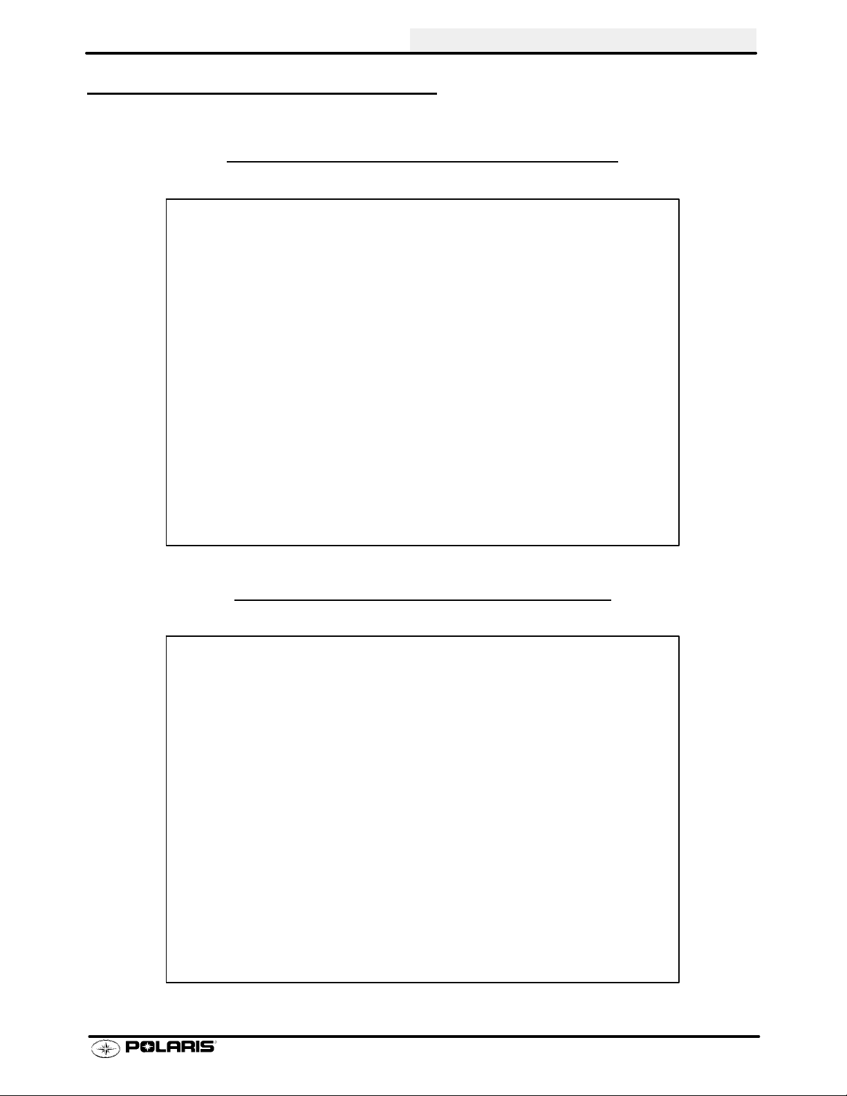
MACHINE DIMENSIONS
SPORTSMAN
30 in
76.2 cm
400
22 in
55.8 cm
41 in
104.1 cm
45 in
114.3 cm
SPORTSMAN 500
32 in
81.2 cm
22 in
55.8 cm
42 in
106.6 cm
46 in
116.8 cm
1.8
Page 11
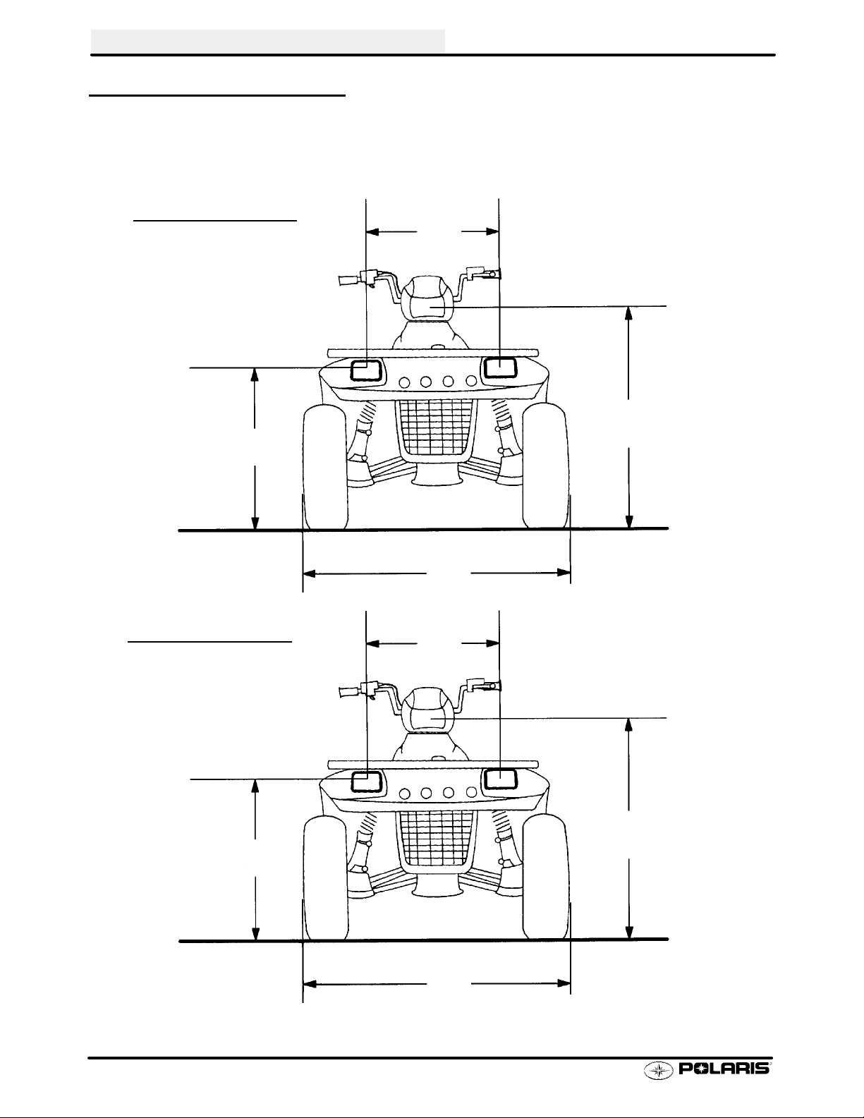
MACHINE DIMENSIONS
SPORTSMAN 400
35 in
89 cm
GENERAL INFORMATION
81 in
205.7 cm
13.5 in
34.29 cm
SPORTSMAN
34 in
86.3 cm
51 in
129.5 cm
500
81 in
205.7 cm
15 in
38.1 cm
50.5 in
128.2 cm
1.9
Page 12
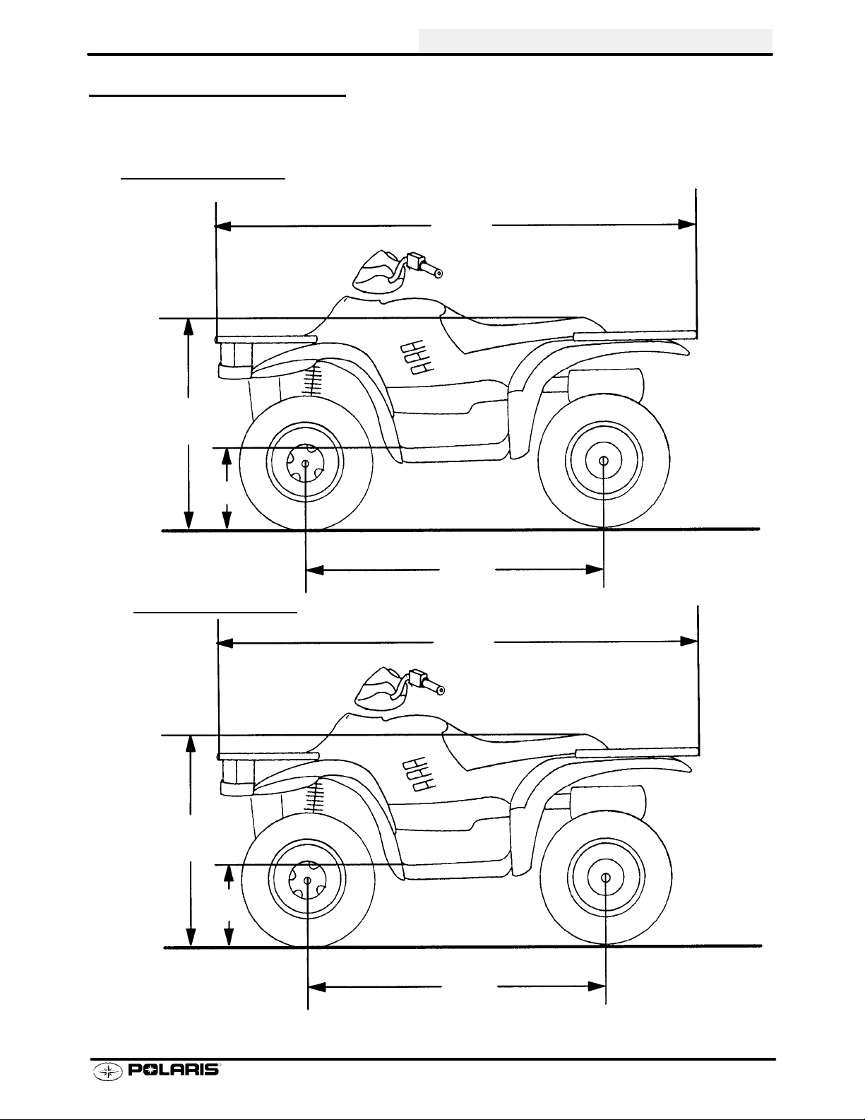
GENERAL INFORMATION
MACHINE DIMENSIONS
SPORTSMAN 400
45 in
114.3 cm
46 in
116.8 cm
9.25 in
23.5 cm
38 in
96.5 cm
47 in
119.4 cm
SPORTSMAN
500
45 in
114.3 cm
48 in
121.9 cm
10 in
25.4 cm
37 in
93.9 cm
47 in
119.3 cm
1.10
Page 13

MODEL: SPORTSMAN 400..........
Altitud
e
Below40
F
+40Fandabov
e
Meter
s
0-180
0
(Feet
)
Above1800
Altitud
e
Meter
s
0-180
0
(Feet
)
180
0-370
0
MODEL NUMBER: A01CH42AA/AB/AC.
ENGINE MODEL: EH42PLE05..
CARBURETION
Type BST 34 Mikuni................
Main Jet 167.5............
Pilot Jet 40.............
Jet Needle JF-3...........
Needle Jet Q-0 (829)...........
Throttle Valve #100........
Pilot Screw 2 3/4 Turns Out..........
Pilot Air Jet 160..........
Valve Seat 1.5...........
Float Height 13.0mm (.51I)±1mm.........
Fuel Octane (R+M/2) 87 Non-Oxygenated or.
89 Oxygenated
CLUTCH
Type PVT....................
Belt 321 1069.....................
Belt Width (Projected) 1.188I (30.18mm).....
Side Angle (Overall) 26°......
Outside Circumference 40.86 ±.12I....
Center Distance 10±.12I (254.5mm)..........
Clutch Offset 0.5I (12.7mm)............
Secondary Spring Black........
Driven Helix 44-36°.............
Spring Position (Helix) 2....
Spring Position (Sheave) 2..
GENERAL INFORMATION
JETTING CHART
Altitude
Meters
(Feet)
CLUTCH CHART
Meters
(Feet)
0-1800
(0-6000)
Above 1800
Above (6000)
0-1800
(0-6000)
1800-3700
(6000-12000)
AMBIENT TEMPERATURE
Below 40°F
Below +5°C
175 167.5
165 160
Shift
Weight Spring Helix
10BH Blue/Green 2+2
10WH Blue/Green 2+2
+40_F andabove
+5_C andabove
Clutch
Driven
ENGINE
Type 4 Cycle, Single Cyl........................
Displacement 425 cc...............
Bore 3.461I (87.9mm).......................
Stroke 2.756I (70mm).....................
Valve Clearance In/Ex 0.006/0.006I@ TDC on compression.......
CompressionRatio 9.2/1 Full Stroke..........
Cooling Liquid....................
Lubrication Type Dry Sump............
Operating RPM±200 6300 RPM.........
Idle RPM±200 (lights off) 1200 RPM.....
Compression Pressure (Std) ±15%.......
1.11
Page 14
GENERAL INFORMATION
MODEL: SPORTSMAN 400............
MODEL NUMBER: A01CH42AA/AB/AC...
ENGINE MODEL: EH42PLE05....
ELECTRICAL FLUID Capacity Type
Flywheel I.D. FF95 Fuel Tank 5.25 gals. (19.9L)...... ..........
CDI Marking CU2565 Injector Oil N / A....... .......... .........
Alternator Output 200 Watts Coolant 2.25 qts. (2.1L) PP6*... ............
Ignition Timing 30° BTDC@5000RPM±2° Transmission 32 oz. PPS*..... ....... .......
Spark Plug / Gap NGK BKR5E / 0.036I (0.9mm) Gearcase Oil (Front) 4 oz. (120ml) 80-90 GL5... . .
Lights: Head Halogen 60/60 watts Gearcase Oil (Center) N / A......
Tail 8.26 watts Gearcase Oil (Rear) N / A........ .
Brake 26.9 watts Engine Counter Bal. N / A...... . .........
Voltage Regulator LR39 Engine Oil 2 qts. (1.9L) PP4*.. .......... ..
Electric Start Standard Brake (Hand) Dot 3....... .......
Brake (Foot) Dot 3........
Front Hubs (AWD) 2.5 oz. (75ml) PDD*...
Shift Selector Box 1 oz. (30ml) PP4*... ..
Lubricant Key
*PP6 Polaris Premium 60/40 Antifreeze/Coolant
*PPS Polaris Premium Synthetic Gear Case Oil
*PP4 Polaris 0W/40 Synthetic Engine Lubricant
*PDD Premium Demand Drive Hub Fluid
SUSPENSION / CHASSIS DRIVE TRAIN
Body Style Gen IV Chain Type Shaft Drive........ .........
Front Suspension MacPherson Strut Gear Reduction-Low 6.69/1.. .
Tow Capacity 850 lbs. (385.6kg) Gear Reduction-Rev 5.17/1...... .
Turning Radius 65I (165.1cm) Gear Reduction-High 3.34/1.....
Toe Out 1/8I-1/4I (3-6.35mm) Front Drive Ratio 2/1........... ....
Ground Clearance 11I (27.94cm) Center Drive Ratio N / A.. ...
Front Vertical Travel 6.7I (17.02cm) Final Drive Ratio 3.16/1....
Rear Suspension Progressive Rate Independent Brake (Hand) Single Lever, Hyd. Disc... .......
Rear Travel 9.5I (24.13cm) Brake ( Auxiliary Foot) Hydraulic........
Rear Shock 2I Twin Tube........
Shock Adjustment Cam..
TIRES
Tire Size - Front 25 x 8 - 12....
Tire Size - Rear 25 x 11 - 10....
Tire Size - Center N / A..
Tire Pressure - F/R 5/5 lbs.
Total Width 46I (116.84cm)........
Total Length 81I (205.74cm).......
Total Height 47I (119.38cm)........
Wheel Base 50.50I (128.27cm).......
Weight - Dry 697 lbs. (316.4kg).......
LOAD CAPACITY
Front Rack (Std) 90 lbs......
Rear Rack (Std) 180 lbs.......
Tongue Weight 30 lbs.....
Tow Hitch Std...........
OPTIONAL SUSPENSION SPRINGS
SOFT STANDARD FIRM
Rear Compression Spring
Front Strut Spring 7041238-067
N/A 7041453-067
Option 61 lb/in.
1.12
Standard 100 lb/in.
7041375-067
Standard 64/113 lb/in.
7041519-067
Option 140 lb/in.
7041450-067
Option 101 lb/in.
Page 15

MODEL: SPORTSMAN 500DUSE..........
Altitud
e
Below40
F
+40Fandabov
e
Meter
s
0-180
0
(Feet
)
Above1800
Altitud
e
Meter
s
0-180
0
(Feet
)
180
0-370
0
MODEL NUMBER: A01CH50AD.
ENGINE MODEL: EH50PLE09..
CARBURETION
Type BST 34 Mikuni................
Main Jet 162.5............
Pilot Jet 40.............
Jet Needle 4HB41-3...........
Needle Jet Q-0 (513)...........
Throttle Valve #100........
Pilot Screw 2 5/8 Turns Out..........
Pilot Air Jet 160..........
Valve Seat 1.5...........
Float Height 13.0mm (.51I)±1mm.........
Fuel Octane (R+M/2) 87 Non-Oxygenated or.
89 Oxygenated
CLUTCH
Type PVT....................
Belt 321 1069.....................
Belt Width (Projected) 1.188I (30.18mm).....
Side Angle (Overall) 26°......
Outside Circumference 40.86 ±.12I....
Center Distance 10±.12I (254.5mm)..........
Clutch Offset 0.5I (12.7mm)............
Secondary Spring White/Green........
Driven Helix Compound (EBS).............
Spring Position (Helix) N/A....
Spring Position (Sheave) N/A..
GENERAL INFORMATION
JETTING CHART
Altitude
Meters
(Feet)
0-1800
(0-6000)
Above 1800
Above (6000)
CLUTCH CHART
Meters
(Feet)
*EBS require no helix/spring adjustment
0-1800
(0-6000)
1800-3700
(6000-12000)
AMBIENT TEMPERATURE
Below 40°F
Below +5°C
170 162.5
160 155
Shift
Weight Spring Helix*
10MH Blue/Green EBS
10WH Blue/Green EBS
+40_F and above
+5_C and above
Clutch
Driven
ENGINE
Type 4 Cycle, Single Cyl........................
Displacement 499 cc...............
Bore 3.6248I (92mm).......................
Stroke 2.955I (75mm).....................
Valve Clearance In/Ex 0.006/0.006I@ TDC on compression.......
Compression Ratio 10/2 Full Stroke..........
Cooling Liquid....................
Lubrication Type Dry Sump............
Operating RPM±200 6000 RPM.........
Idle RPM±200 (lights off) 1200 RPM.....
Compression Pressure (Std) ±15%.......
1.13
Page 16

GENERAL INFORMATION
MODEL: SPORTSMAN 500 DUSE............
MODEL NUMBER: A01CH50AD...
ENGINE MODEL: EH50PLE09....
ELECTRICAL FLUID Capacity Type
Flywheel I.D. FF97 Fuel Tank 5.25 gals. (19.9L)...... ..........
CDI Marking CU2570 Injector Oil N / A....... .......... .........
Alternator Output 250 Watts Coolant 2.25 qts. (2.1L) PP6*... ............
Ignition Timing 30° BTDC@5000RPM±2° Transmission 32 oz. PPS*..... ....... .......
Spark Plug / Gap NGK BKR5E / 0.036I (0.9mm) Gearcase Oil (Front) 4 oz. (120ml) 80-90 GL5... . .
Lights: Head Halogen 60/60 watts Gearcase Oil (Center) N / A......
Tail 8.26 watts Gearcase Oil (Rear) N / A........ .
Brake 26.9 watts Engine Counter Bal. N / A...... . .........
Voltage Regulator LR39 Engine Oil 2 qts. (1.9L) PP4*.. .......... ..
Electric Start Standard Brake (Hand) Dot 3....... .......
Brake (Foot) Dot 3........
Front Hubs (AWD) 2.5 oz. (75ml) PDD*...
Shift Selector Box 1 oz. (30ml) PP4*... ..
Lubricant Key
*PP6 Polaris Premium 60/40 Antifreeze/Coolant
*PPS Polaris Premium Synthetic Gear Case Oil
*PP4 Polaris 0W/40 Synthetic Engine Lubricant
*PDD Premium Demand Drive Hub Fluid
SUSPENSION / CHASSIS DRIVE TRAIN
Body Style Gen IV Chain Type Shaft Drive........ .........
Front Suspension MacPherson Strut Gear Reduction-Low 6.69/1.. .
Tow Capacity 1225 lbs. (555.6kg) Gear Reduction-Rev 5.17/1...... .
Turning Radius 65I (165.1cm) Gear Reduction-High 3.34/1.....
Toe Out 1/8I-1/4I (3-6.35mm) Front Drive Ratio 2/1........... ....
Ground Clearance 11I (27.94cm) Center Drive Ratio N / A.. ...
Front Vertical Travel 6.7I (17.02cm) Final Drive Ratio 3.16/1....
Rear Suspension Progressive Rate Independent Brake (Hand) Single Lever, Hyd. Disc... .......
Rear Travel 9.5I (24.13cm) Brake ( Auxiliary Foot) Hydraulic........
Rear Shock 2I Twin Tube........
Shock Adjustment Cam..
TIRES
Tire Size - Front 25 x 8 - 12....
Tire Size - Rear 25 x 11 - 10....
Tire Size - Center N / A..
Tire Pressure - F/R 5/5 lbs.
Total Width 46I (116.84cm)........
Total Length 81I (205.74cm).......
Total Height 47I (119.38cm)........
Wheel Base 50.50I (128.27cm).......
Weight - Dry 697 lbs. (316.4kg).......
LOAD CAPACITY
Front Rack (Std) 90 lbs......
Rear Rack (Std) 180 lbs.......
Tongue Weight 35 lbs.....
Tow Hitch Std...........
OPTIONAL SUSPENSION SPRINGS
SOFT STANDARD FIRM
Rear Compression Spring
Front Strut Spring 7041238-067
N/A 7041453-067
Option 61 lb/in.
1.14
Standard 100 lb/in.
7041375-067
Standard 64/113 lb/in.
7041519-067
Option 140 lb/in.
7041450-067
Option 101 lb/in.
Page 17
MODEL: SPORTSMAN 500 H.O...........
Altitud
e
Below40
F
+40Fandabov
e
Meter
s
0-180
0
(Feet
)
Above1800
Altitud
e
Meter
s
0-180
0
(Feet
)
180
0-370
0
MODEL NUMBER: A01CH50AA/AB/AE/AF/AJ.
ENGINE MODEL: EH50PLE13..
CARBURETION
Type BST 40 Mikuni................
Main Jet 152.5............
Pilot Jet 40.............
Jet Needle KE-3 (683)...........
Needle Jet X-6...........
Throttle Valve #120........
Pilot Screw 2 1/2 Turns Out..........
Pilot Air Jet 1.3..........
Valve Seat 1.5...........
Float Height 14.7mm (.58I)±1mm.........
Fuel Octane (R+M/2) 87 Non-Oxygenated or.
89 Oxygenated
CLUTCH
Type PVT....................
Belt 321 1069.....................
Belt Width (Projected) 1.188I (30.18mm).....
Side Angle (Overall) 26°......
Outside Circumference 40.86 ±.12I....
Center Distance 10±.12I (254.5mm)..........
Clutch Offset 0.5I (12.7mm)............
Secondary Spring White/Yellow........
Driven Helix Compound (EBS).............
Spring Position (Helix) N/A....
Spring Position (Sheave) N/A..
GENERAL INFORMATION
JETTING CHART
Altitude
Meters
(Feet)
0-1800
(0-6000)
Above 1800
Above (6000)
CLUTCH CHART
Meters
(Feet)
*EBS require no helix/spring adjustment
0-1800
(0-6000)
1800-3700
(6000-12000)
AMBIENT TEMPERATURE
Below 40°F
Below +5°C
157.5 152.5
150 145
Shift
Weight Spring Helix*
10WH Blue/Green EBS
10RH Blue/Green EBS
+40_F and above
+5_C and above
Clutch
Driven
ENGINE
Type 4 Cycle, Single Cyl........................
Displacement 499 cc...............
Bore 3.6248I (92mm).......................
Stroke 2.955I (75mm).....................
Valve Clearance In/Ex 0.006/0.006I@ TDC on compression.......
Compression Ratio 10/2 Full Stroke..........
Cooling Liquid....................
Lubrication Type Dry Sump............
Operating RPM±200 6500 RPM.........
Idle RPM±200 (lights off) 1200 RPM.....
Compression Pressure (Std) ±15%.......
1.15
Page 18
GENERAL INFORMATION
MODEL: SPORTSMAN 500 H.O.............
MODEL NUMBER: A01CH50AA/AB/AE/AF/AJ...
ENGINE MODEL: EH50PLE13....
ELECTRICAL FLUID Capacity Type
Flywheel I.D. FF97 Fuel Tank 5.25 gals. (19.9L)...... ..........
CDI Marking CU2570 Injector Oil N / A....... .......... .........
Alternator Output 250 Watts Coolant 2.25 qts. (2.1L) PP6*... ............
Ignition Timing 30° BTDC@5000RPM±2° Transmission 32 oz. PPS*..... ....... .......
Spark Plug / Gap NGK BKR5E / 0.036I (0.9mm) Gearcase Oil (Front) 4 oz. (120ml) 80-90 GL5... . .
Lights: Head Halogen 60/60 watts Gearcase Oil (Center) N / A......
Tail 8.26 watts Gearcase Oil (Rear) N / A........ .
Brake 26.9 watts Engine Counter Bal. N / A...... . .........
Voltage Regulator LR39 Engine Oil 2 qts. (1.9L) PP4*.. .......... ..
Electric Start Standard Brake (Hand) Dot 3....... .......
Brake (Foot) Dot 3........
Front Hubs (AWD) 2.5 oz. (75ml) PDD*...
Shift Selector Box 1 oz. (30ml) PP4*... ..
Lubricant Key
*PP6 Polaris Premium 60/40 Antifreeze/Coolant
*PPS Polaris Premium Synthetic Gear Case Oil
*PP4 Polaris 0W/40 Synthetic Engine Lubricant
*PDD Premium Demand Drive Hub Fluid
SUSPENSION / CHASSIS DRIVE TRAIN
Body Style Gen IV Chain Type Shaft Drive........ .........
Front Suspension MacPherson Strut Gear Reduction-Low 6.69/1.. .
Tow Capacity 1225 lbs. (555.6kg) Gear Reduction-Rev 5.17/1...... .
Turning Radius 65I (165.1cm) Gear Reduction-High 3.34/1.....
Toe Out 1/8I-1/4I (3-6.35mm) Front Drive Ratio 2/1........... ....
Ground Clearance 11I (27.94cm) Center Drive Ratio N / A.. ...
Front Vertical Travel 6.7I (17.02cm) Final Drive Ratio 3.16/1....
Rear Suspension Progressive Rate Independent Brake (Hand) Single Lever, Hyd. Disc... .......
Rear Travel 9.5I (24.13cm) Brake ( Auxiliary Foot) Hydraulic........
Rear Shock 2I Twin Tube........
Shock Adjustment Cam..
TIRES
Tire Size - Front 25 x 8 - 12....
Tire Size - Rear 25 x 11 - 10....
Tire Size - Center N / A..
Tire Pressure - F/R 5/5 lbs.
Total Width 46I (116.84cm)........
Total Length 81I (205.74cm) (AA/AB/AE).......
85I (215.9cm) (AF/AJ)...................
Total Height 47I (119.38cm)........
Wheel Base 50.50I (128.27cm).......
Weight - Dry 697 lbs. (316.4kg) (AA/AB/AE).......
750 lbs. (340kg) (AF/AJ)...................
LOAD CAPACITY
Front Rack (Std) 90 lbs......
Rear Rack (Std) 180 lbs.......
Tongue Weight 35 lbs.....
Tow Hitch Std...........
OPTIONAL SUSPENSION SPRINGS
SOFT STANDARD FIRM
Rear Compression Spring
Front Strut Spring 7041238-067
N/A 7041453-067
Option 61 lb/in.
1.16
Standard 100 lb/in.
7041375-067
Standard 64/113 lb/in.
7041519-067
Option 140 lb/in.
7041450-067
Option 101 lb/in.
Page 19
PUBLICATION NUMBERS
GENERAL INFORMATION
Year Model Model No. Owner’s Manual
PN
2001 Sportsman 400 A01CH42AA/AB/AC 9915754 9916443 9916444
2001 Sportsman 500 DUSE A01CH50AD 9915754 9916002 9916003
2001 Sportsman 500 H.O. A01CH50AA/AB/AE/
AF/AJ
When ordering service parts be sure to use the correct parts manual.
9915754 9916446 9916447
Parts
Manual PN
Micro Fiche PN
PAINT CODES
PAINTED PART COLOR
DESCRIPTION
(400) Springs/Rims Black 9440 P-067
(500) Springs/Rims Black 9440 P-067
(500) Opt. B Springs Black 9440 P-067
(500) Opt. B Rims Brushed Aluminum N/A P-117
FRAME COLOR - (All) P067 Medium Gloss Black 9440 / 8520147.
Order direct from Midwest Industrial Coatings (952-942-1840). Mix as directed.
DITZLER
NUMBER
POLARIS
NUMBER
Parts
1.17
Page 20
GENERAL INFORMATION
STANDARD TORQUE SPECIFICATIONS
The following torque specifications are to be used as a general guideline. There are exceptions in the steering,
suspension, and engine areas. Always consult the exploded views in each manual section for torque values of
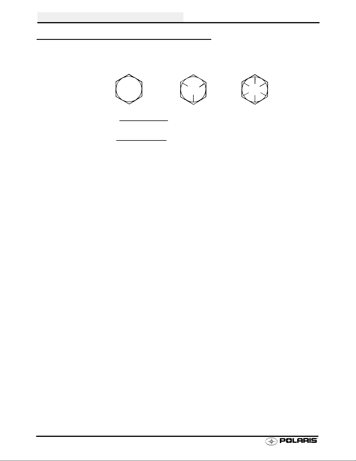
fasteners before using standard torque.
Bolt Size Threads/In Grade 2 Grade 5 Grade 8
T orque in. lbs. (Nm)
#10 - 24 27 (3.1) 43 (5.0) 60 (6.9).............. ................ ..............
#10 - 32 31 (3.6) 49 (5.6) 68 (7.8).............. ................ ..............
T o rque ft. lbs. (Nm)*
1/4 - 20 5 (7) 8(11) 12 (16).............. .................. ................
1/4 - 28 6 (8) 10(14) 14 (19).............. .................. ..............
5/16 - 18 11 (15) 17 (23) 25 (35).............. ................ ..............
5/16 - 24 12 (16) 19 (26) 29 (40).............. ................ ..............
3/8 - 16 20 (27) 30 (40) 45 (62).............. ................ ..............
3/8 - 24 23 (32) 35 (48) 50 (69).............. ................ ..............
7/16 - 14 30 (40) 50 (69) 70 (97).............. ................ ..............
7/16 - 20 35 (48) 55 (76) 80 (110).............. ................ ..............
1/2 - 13 50 (69) 75 (104) 110 (152).............. ................ .............
1/2 - 20 55 (76) 90 (124) 120 (166).............. ................ .............
Metric
6 x 1.0 72-78 In. lbs.
8 x 1.25 14-18 ft. lbs.
10 x 1.25 26-30 ft. lbs.
*To convert ft. lbs. to Nm multiply foot pounds by .1.382
*To convert Nm to ft. lbs. multiply Nm by .7376.
SPECIFIC TORQUE VALUES OF FASTENERS
Refer to exploded views in the appropriate section.
1.18
Page 21

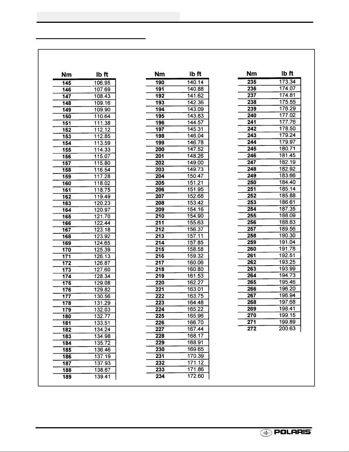
TORQUE CONVERSIONS
Newton Meter to Pound Foot and Pound Inch
GENERAL INFORMATION
1.19
Page 22
GENERAL INFORMATION
TORQUE CONVERSIONS
Newton Meter to Pound Foot and Pound Inch
1.20
Page 23

DECIMAL EQUIVALENTS
1/64 .0156.........................
1/32 .0312 1 mm = .0394″................... ................
3/64 .0469.........................
1/16 .0625..............
5/64 .0781 2 mm = .0787″......................... ................
3/32 .0938...................
7/64 .1094 3 mm = .1181″....................... ................
1/8 . 1250. .......
9/64 .1406.........................
5/32 .1563 4 mm = .1575″................... ................
11/64 .1719........................
3/16 .1875 5 mm = .1969″.............. ................
13/64 .2031........................
7/32 .2188...................
15/64 .2344 6 mm = .2362″........................ ................
1/4 .25..........
17/64 .2656 7 mm = .2756″........................ ................
9/32 .2813...................
19/64 .2969........................
5/16 .3125 8 mm = .3150″.............. ................
21/64 .3281........................
11/32 .3438 9 mm = .3543″.................. ................
23/64 .3594........................
3/8 .375..........
25/64 .3906 10 mm = .3937″........................ ................
13/32 .4063..................
27/64 .4219 1 1mm = .4331″........................ ................
7/16 .4375..............
29/64 .4531........................
15/32 .4688 12 mm = .4724″.................. ................
31/64 .4844........................
1/2 .5 13 mm = .5118.......... ...................
33/64 .5156........................
17/32 .5313..................
35/64 .5469 14 mm = .5512″........................ ................
9/16 .5625..............
37/64 .5781 15 mm = .5906″........................ ................
19/32 .5938..................
39/64 .6094........................
5/8 .625 16 mm = .6299″.......... .................
41/64 .6406........................
21/32 .6563 17 mm = .6693″.................. ................
43/64 .6719.......................
/16 .6875.............
1 1
45/64 .7031 18 mm = .7087″........................ ................
23/32 .7188..................
47/64 .7344 19 mm = .7480″........................ ................
3/4 .75..........
49/64 .7656........................
25/32 .7813 20 mm = .7874″.................. ................
51/64 .7969........................
13/16 .8125 21 mm = .8268″............. ................
53/64 .8281........................
27/32 .8438..................
55/64 .8594 22 mm = .8661″........................ ................
7/8 .875..........
57/64 .8906 23 mm = .9055″........................ ................
29/32 .9063..................
59/64 .9219.......................
15/16 .9375 24 mm = .9449″............. ................
61/64 .9531........................
31/32 .9688 25 mm = .9843.................. ................
63/64 .9844........................
11.0............
GENERAL INFORMATION
1.21
Page 24
GENERAL INFORMATION
CONVERSION TABLE
Unit of Measure Multiplied by Converts to
ft. lbs. x12 =in.lbs.
in. lbs. x .0833 = ft. lbs.
ft. lbs. x 1.356 =Nm
in. lbs. x .0115 =kg-m
Nm x .7376 = ft.lbs.
kg-m x 7.233 = ft. lbs.
kg-m x 86.796 =in.lbs.
kg-m x10 =Nm
in. x 25.4 =mm
mm x .03937 =in.
in. x2.54 =cm
mile (mi.) x1.6 =km
km x .6214 = mile (mi.)
Ounces (oz) x 28.35 = Grams (g)
Fluid Ounces (fl. oz.) x 29.57 = Cubic Centimeters (cc)
Cubic Centimeters (cc) x .03381 = Fluid Ounces (fl. oz.)
Grams (g) x 0.035 = Ounces (oz)
lb. x .454 =kg
kg x 2.2046 =lb.
Cubic inches (cu in) x 16.387 = Cubic centimeters (cc)
Cubic centimeters (cc) x 0.061 = Cubic inches (cu in)
Imperial pints (Imp pt) x 0.568 = Liters (l)
Liters (l) x1.76 = Imperial pints (Imp pt)
Imperial quarts (Imp qt) x 1.137 = Liters (l)
Liters (l) x0.88 = Imperial quarts (Imp qt)
Imperial quarts (Imp qt) x 1.201 = US quarts (US qt)
US quarts (US qt) x 0.833 = Imperial quarts (Imp qt)
US quarts (US qt) x 0.946 = Liters (l)
Liters (l) x 1.057 = US quarts (US qt)
US gallons (US gal) x 3.785 =Liters (l)
Liters (l) x 0.264 = US gallons (US gal)
Pounds - force per square inch (psi) x 6.895 = Kilopascals (kPa)
Kilopascals (kPa) x 0.145 = Pounds - force per square inch (psi)
Kilopascals (kPa) x0.01 = Kilograms - force per square cm
Kilograms - force per square cm x 98.1 = Kilopascals (kPa)
π (3.14) xR2x H (height) = Cylinder Volume
°Cto°F: 9 (°C + 40) ÷ 5-40=°F
°Fto°C: 5 (°F + 40) ÷ 9-40=°C
1.22
Page 25
GENERAL INFORMATION
SAE TAP DRILL SIZES
Thread Size Drill Size Thread Size Drill Size
#0-80 3/64
#1-64 53
#1-72 53
#2-56 51
#2-64 50
#3-48 5/64
#3-56 45
#4-40 43
#4-48 42
#5-40 38
#5-44 37
#6-32 36
#6-40 33
#8-32 29
#8-36 29
#10-24 24
#10-32 21
#12-24 17
#12-28 4.6mm
1/4-20 7
1/4-28 3
5/16-18 F
5/16-24 I
3/8-16 O
3/8-24 Q
7/16-14 U
7/16-20 25/64
1/2-13 27/64
1/2-20 29/64
9/16-12 31/64
9/16-18 33/64
5/8-11 17/32
5/8-18 37/64
3/4-10 21/32
3/4-16 11/16
7/8-9 49/64
7/8-14 13/16
1-8 7/8
1-12 59/64
1 1/8-7 63/64
1 1/8-12 1 3/64
11/4-7 17/64
1 1/4-12 1 11/64
11/2-6 111/32
1 1/2-12 1 27/64
13/4-5 19/16
1 3/4-12 1 43/64
2-4 1/2 1 25/32
2-12 1 59/64
2 1/4-4 1/2 2 1/32
21/2-4 21/4
23/4-4 21/2
3-4 2 3/4
METRIC TAP DRILL SIZES
Tap Size Drill Size Decimal Equivalent Nearest Fraction
3x.50
3x.60
4x.70
4x.75
5x.80
5x.90
6 x 1.00
7 x 1.00
8 x 1.00
8 x 1.25
9 x 1.00
9 x 1.25
10 x 1.25
10 x 1.50
11 x 1.50
12 x 1.50
12 x 1.75
#39
3/32
#30
1/8
#19
#20
#9
16/64
J
17/64
5/16
5/16
11/32
R
3/8
13/32
13/32
0.0995
0.0937
0.1285
0.125
0.166
0.161
0.196
0.234
0.277
0.265
0.3125
0.3125
0.3437
0.339
0.375
0.406
0.406
3/32
3/32
1/8
1/8
11/64
5/32
13/64
15/64
9/32
17/64
5/16
5/16
11/32
11/32
3/8
13/32
13/32
1.23
Page 26

GENERAL INFORMATION
GLOSSARY OF TERMS
ABDC: After bottom dead center.
ACV: Alternating current voltage.
Alternator: Electrical generator producing voltage alternating current.
ATDC: After top dead center.
BBDC: Before bottom dead center.
BDC: Bottom dead center.
BTDC: Before top dead center.
CC: Cubic centimeters.
Center Distance: Distance between center of crankshaft and center of driven clutch shaft.
Chain Pitch: Distance between chain link pins (No. 35 = 3/8″ or 1 cm). Polaris measures chain length in number of
pitches.
CI: Cubic inches.
Clutch Buttons: Plastic bushings which transmit rotation of the clutch to the movable sheave in the drive and driven
clutch.
ClutchOffset: Driveand drivenclutchesareoffsetsothat drive beltwillstaynearlystraightasit movesalongtheclutch
face.
Clutch Weights: Three levers in the drive clutchwhich relative totheir weight, profile andengine RPM causethe drive
clutch to close.
Condenser/Capacitor: A storage reservoir for DC voltage.
Crankshaft Run-Out: Run-out or “bend” of crankshaft measured with a dial indicator while crankshaft is supported
between centers on V blocks or resting in crankcase. Measure at various points especially at PTO.
DCV: Direct current voltage.
Dial Bore Gauge: A cylinder measuring instrument which uses a dial indicator. Good for showing taper and
out-of-round in the cylinder bore.
Electrical Open: Open circuit. An electrical circuit which isn’t complete.
Electrical Short: Short circuit. An electrical circuit which is completed before the current reaches the intended load.
(i.e. a bare wire touching the chassis).
End Seals: Rubber seals at each end of the crankshaft.
Engagement RPM: Engine RPM at which the drive clutch engages to make contact with the drive belt.
ft.: Foot/feet.
Foot Pound: Ft. lb. A force of one pound at the end of a lever one foot in length, applied in a rotational direction.
g: Gram. Unit of weight in the metric system.
gal.: Gallon.
HP: Horsepower.
ID: Inside diameter.
in.: Inch/inches.
Inch Pound: In. lb. 12 in. lbs. = 1 ft. lb.
kg/cm2: Kilograms per square centimeter.
kg-m: Kilogram meters.
Kilogram/meter: A force of one kilogram at the end of a lever one meter in length, applied in a rotational direction.
lorltr: Liter.
lbs/in2: Pounds per square inch.
Left Side: Always referred to based on normal operating position of the driver.
1.24
Page 27

GENERAL INFORMATION
GLOSSARY OF TERMS
m: Meter/meters.
Mag: Magneto.
Magnetic Induction: As a conductor (coil) is moved through a magnetic field, a voltage will be generated in the
windings. Mechanical energy is converted to electrical energy in the stator.
mi.: Mile/miles.
mm: Millimeter. Unit of length in the metric system. 1mm = approximately .040″.
Nm: Newton meters.
OD: Outside diameter.
Ohm: The unit of electrical resistance opposing current flow.
oz.: Ounce/ounces.
Piston Clearance: Total distance between piston and cylinder wall.
psi.: Pounds per square inch.
PTO: Power take off.
PVT: Polaris Variable Transmission (Drive Clutch System)
qt.: Quart/quarts.
RPM: Revolutions per minute.
Regulator: Voltage regulator. Regulates battery charging system output at approx. 14.5 DCV as engine RPM
increases.
Reservoir Tank: The fill tank in the liquid cooling system.
Resistance: Inthemechanicalsense,frictionor load. Inthe electricalsense, ohms. Bothresultinenergy conversionto
heat.
Right Side: Always referred to based on normal operating position of the driver.
RPM: Revolutions per minute.
Secondary Clutch: Driven clutch on chaincase or jackshaft.
SeizedPiston: Galling ofthesidesofa piston. Usually thereis atransferof aluminumfromthepistononto thecylinder
wall. Possible causes: 1) improper lubrication; 2) excessive temperatures; 3) insufficient piston clearance; 4) stuck
piston rings.
Stator Plate: Theplate mounted under the flywheel supporting the battery charging coils.
TDC: Top dead center. Piston’s most outward travel from crankshaft.
Volt: Theunit of measure for electrical pressure of electromotive force. Measured by a voltmeter in parallel with the
circuit.
Watt: Unit of electrical power. Watts = amperes x volts.
WOT: Wide open throttle.
1.25
Page 28

CHAPTER 2
MAINTENANCE
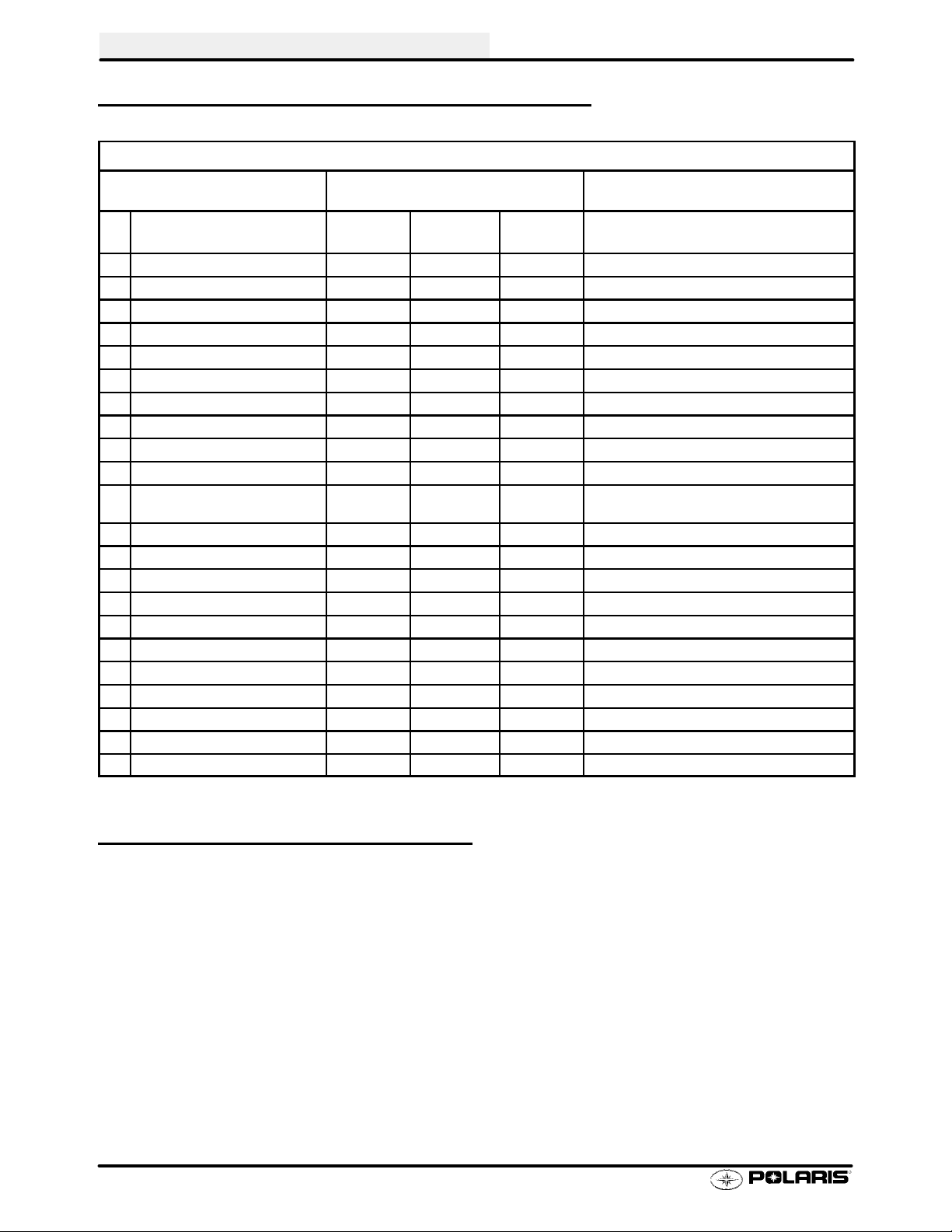
Periodic Maintenance Chart 2.1-2.2....................
Pre-Ride Inspection 2.2...........................
Recommended Lubricants and Capacities 2.3.......
Lubricant and Maintenance Product Numbers 2.4....
Lubrication Charts 2.5-2.8............................
Front Gearcase Lubrication 2.9...................
Transmission Lubrication 2.10......................
Transmission LInkage Adjustment 2.11-2.12..............
Carburetor Adjustments 2.13-2.15.......................
Fuel System 2.16-2.17.................................
Compression Test 2.18............................
Battery Maintenance 2.19..........................
Electrical 2.20....................................
Coolant System Maintenance 2.21-2.22..................
Air Filter Service 2.23..............................
Air Box Sediment Tube Service 2.24.................
Breather Filter 2.24................................
Recoil Housing 2.25...............................
Oil Change/Filter 2.26-2.27.............................
Valve Clearance 2.28-2.29..............................
Steering and Toe Alignment 2.30-2.32....................
Front Hub Maintenance 2.33.......................
Exhaust System Maintenance 2.34..................
Brake System Service 2.35-2.36.........................
Suspension Service 2.37...........................
Controls 2.38.....................................
Wheel Removal/Installation 2.39....................
Tire Inspection 2.40...............................
2
Page 29
MAINTENANCE
PERIODIC MAINTENANCE CHART
Inspection, adjustment and lubrication intervals of important components is listed in the following chart.
Maintenance intervals are based upon average riding conditions and a vehicle speed of approximately 10 mph.
Inspect, clean, lubricate, adjust or replace parts as necessary. NOTE: Inspection may reveal the need for replacement parts. Always use genuine Polaris parts.
HCAUTION: Due to the nature of these adjustments, it is recommended that service be performed by an
authorized Polaris dealer.
"Vehicles subjected to severe use (operation in wet or dusty areas, low speed heavy load operation, prolonged
idle) should be inspected and serviced more frequently. For engine oil, short trip cold weather riding also constitutes severe use. Pay specialattention to oil level. Arise in oil level in coldweather can indicate moisturecollecting in the oil tank. Change oil immediately if oil level begins to rise.
E Emission Control System Service (California).
PERIODIC MAINTENANCE - ENGINE
Frequency
(Whichever comes first)
Item Hours Calendar Miles
(Km)
Engine Oil - Level/Change 100 hrs 6 months 1000 (1600) Check Level Daily; Break In service at 1 month
E"
Oil Filter 100 hrs 6 months 1000 (1600) Replace with oil change
E
Air Filter - Foam Pre-Cleaner Daily Daily Inspect-Clean & oil more often in dirty conditions.
E"
Air Filter - Main Element Weekly Weekly Inspect - Replace if necessary
E"
" Air Box Sediment Tube - Daily Drain deposits whenever visible
" Engine Breather Filter 20 hrs Monthly 200 (320) Inspect and replace if necessary
" Oil Tank Vent Hose 100 hrs 12 months 1000 (1600) Inspect hose routing /hose condition
Valve Clearance 100 hrs 12 months 1000 (1600) Inspect/Adjust
EH
Idle Speed As required As required Adjust
E
H Throttle Cable / ETC Switch 50 hrs 6 months 500 (800) Inspect -Adjust, Lubricate, Replace if necessary
Choke (Enricher) Cable 50 hrs 6 months 500 (800) Inspect -Adjust, Lubricate, Replace if necessary
Carburetor Float Bowl 50 hrs 6 months 500 (800) Drain bowl periodically and prior to storage
Carburetor Air Intake Ducts/Flange 50 hrs 6 months 500 (800) Inspect all ducts for proper sealing/air leaks
Fuel System 100 hrs 12 months 1000 (1600) Check for leaks at tank cap, lines, fuel valve, filter,
EH
Fuel Filter 100 hrs 12 months 1000 (1600) Replace filter annually
EH
Coolant/Level Inspection Daily Daily Replace engine coolant every 2 years
Coolant Strength / Pressure Test
System
Radiator 100 hrs 12 months 1000 (1600) Inspect / Clean external surface
CoolingSystemHoses 100 hrs 12 months 1000 (1600) Inspect
Engine Mounts 100 hrs 12 months 1000 (1600) Inspect
Drain Recoil Housing Weekly Weekly More often if operating in wet environment
Exhaust Muffler / Pipe 100 hrs 12 months 1000 (1600)
100 hrs 6 months 1000 (1600) Inspect strength seasonally; Pressure test sys-
pump & carburetor. Replace lines every 2 years.
tem annually
ELECTRICAL
Spark Plug 100 hrs 12 months 1000 (1600) Inspect - Replace if necessary
E
Wiring 100 hrs 12 months 1000 (1600) Inspect for abrasion, routing, security
Ignition Timing 100 hrs 12 months 1000 (1600) Inspect
Battery 20 hrs Monthly 200 (320) Check terminals; Clean; Check fluid level
Headlight Aim As required As required Adjust if Necessary
Headlamp Inspection Daily Daily Check operation daily; Apply Nyogelt Grease
Tail Lamp Inspection Daily Daily Check Operation Daily; Apply Nyogelt Grease
to connector when lamp is replaced
to socket when lamp is replaced
Remarks
2.1
Page 30
MAINTENANCE
PERIODIC MAINTENANCE CHART, CONT.
CHASSIS
Frequency
(Whichever comes first)
Item Hours Calendar Miles
(Km)
" General Lubrication 50 hrs 3 months 500 (800) Lubricate All Fittings, Pivots, Cables, Etc.
" Front Hubs/Fluid Check 50 hrs 6 months 500 (800) Check monthly
" Front Hubs/Fluid Change 100 hrs 12 months 1000 (1600) Check monthly
" Front Gearcase Lubricant 100 hrs 12 months 1000 (1600) Inspect Monthly; Change Annually
Drive Belt 50 hrs 6 months 500 (800) Inspect - Adjust, Replace if Necessary
Clutches (Drive And Driven) 100 hrs 12 months 1000 (1600) Inspect, Clean
" Transmission Oil Level 25 hrs Monthly 250 (400) Inspect Monthly; Change Annually
Shift Linkage 50 hrs 6 months 500 (800) Inspect,Lubricate, Adjust
Shift Selector Box 200hrs 24 months 2000 (3200) Change Lubricant Every Two Years
H Steering 50 hrs 6 months 500 (800) Inspect Daily, Lubricate
H Toe Adjustment As required As required Periodic Inspection, Adjust When Parts are Re-
placed
" Front Suspension 50 hrs 6 months 500 (800) Inspect - Lubricate
" Rear Suspension 50 hrs 6 months 500 (800) Inspect - Lubricate
Tires Pre-ride Pre-ride Inspect Daily, Pre-Ride Inspection Item
H Brake Fluid 200 hrs 24 months 2000 (3200) Change Every Two Years
" Brake Fluid Level Pre-ride Pre-ride Inspect Daily, Pre-Ride Inspection Item
" Brake Lever Travel Pre-ride Pre-ride Inspect Daily, Pre-Ride Inspection Item
H Brake Pad Wear 10 hrs Monthly 100 (160) Inspect Periodically
Auxiliary Brake Adjustment As required As required Inspect Deflection Daily; Adjust
Brake System Pre-ride Pre-ride Pre-Ride Inspection Item
Wheels Pre-ride Pre-ride Pre-Ride Inspection Item
Frame Nuts, Bolts, Fasteners Pre-ride Pre-ride Pre-Ride Inspection Item
Remarks
PRE-RIDE / DAILY INSPECTION
Perform the following pre-ride inspection daily, and when servicing the vehicle at each scheduled maintenance.
S Tires - check condition and pressures
S Fuel and oil tanks - fill both tanks to their proper level; Do not overfill oil tank
S All brakes - check operation and adjustment (includes auxiliary brake)
S Throttle - check for free operation and closing
S Headlight/Taillight/Brakelight - check operation of all indicator lights and switches
S Engine stop switch - check for proper function
S Wheels - check for tightness of wheel nuts and axle nuts; check to be sure axle nuts are se-
cured by cotte r pins
S Air cleaner element - check for dirt; clean or replace
S Steering - check for free operation noting any unusual looseness in any area
S Loose parts - visually inspect vehicle for any damaged or loose nuts, bolts or fasteners
S Engine coolant - check for proper level at the recovery bottle
2.2
Page 31

MAINTENANCE
RECOMMENDED LUBRICANTS - QUICK REFERENCE
LUBRICANTS AND MAINTENANCE PRODUCT PART NUMBERS ARE LISTED ON PAGE 2.4. REFER
TO SPECIFICATIONS CHAPTER 1 FOR CAPACITY INFORMA
Item
Engine Oil Polaris Premium 4
Synthetic, 0W/40
Transmission Polaris Synthetic Gear
Case Lubricant
Front Gear Case Premium Front Gearcase
Fluid or GL5 80-90 Gear
Lube
Gear Shift Selector
Box
Coolant Level Polaris Premium 60/40
Front Hubs Premium Demand Drive
Brake Fluid Polaris DOT 3 Brake Fluid Fill to indicated level inside reservoir. 2.35
Polaris 0W/40 Synthetic
Engine Lubricant or
10W Motor Oil
Pre-mixed Antifreeze/
Coolant or a 50/50 mixture
high quality antifreeze/
coolant and distilled water
Hub Fluid
Type Notes See
Add to proper level on dipstick. 2.26-2.27
Refer to procedures outlined later in this
chapter.
Refer to procedures outlined later in this
chapter.
Oil in selector box should be at the center
line of the shift selector plungers. Do not
overfill or the selector may hydro-lock.
Fill reservoir tank to full line. Add if necessary. If reservoir was empty or extremely
low, allow engine and cooling system to
cool completely and check level in radiator. Fill to top of filler neck.
Fill hub at 4:00 or 8:00 position until fluid
trickles out. Do not force fluid into hub.
TION.
Pages
2.10
2.9
8.4
2.22
2.33
COLD WEATHER KITS FOR 4 CYCLE ATVS
Oil Tank Cover -- PN 287187
Engine Heater -- PN 2871507
Oil Tank Heater -- PN 2871873
2.3
Page 32

MAINTENANCE
POLARIS PREMIUM LUBRICANT AND MAINTENANCE PRODUCT PART
Part No. Description
2870791 Fogging Oil
2871281 Engine Oil (Quart) Premium 4 Synthetic 0-W40 (4-Cycle)
2871567 Engine Oil (16 Gallon) Premium 4 Synthetic 0-W40 (4-Cycle)
2871477 Premium Synthetic Gearcase Lubricant (1 Gal.)
2871478 Premium Synthetic Gearcase Lubricant (12 oz.. bottle)
2870465 Oil Pump for Gearcase Oil
2871653 Premium Front Gearcase Fluid (12 oz..)
2871322 Premium All Season Grease (3 oz.. cartridge)
2871423 Premium All Season Grease (14 oz.. cartridge)
2871460 Starter Drive Grease
2871515 Premium U-Joint Lube (3 oz..)
2871551 Premium U-Joint Lube (14 oz..)
2871312 Grease Gun Kit
1350046 CV Joint Grease Pack (30g)
1350047 CV Joint Grease Pack 50g
2871329 Dielectric Grease (Nyogelt)
2871654 Premium Demand Drive Hub Fluid (12 oz..)
2871323 60/40 Coolant Gallon
2871534 60/40 Coolant Quart
2870585 Loctitet Primer N, Aerosol, 25g
2871949 Loctitet Threadlock 242 (50ml.)
2871950 Loctitet Threadlock 242 (6ml.)
2871951 Loctitet Threadlock 262 (50ml.)
2871952 Loctitet Threadlock 262 (6ml.)
2871953 Loctitet Threadlock 271 (6ml.)
2871954 Loctitet Threadlock 271 (36ml.)
2870584 Loctitet RC 680-Retaining Compound (10ml. )
2870587 Loctitet 518 Gasket Eliminator / Flange Sealant (50ml.)
2871326 Premium Carbon Clean 12 oz..
2870652 Fuel Stabilizer 16 oz..
2871957 Black RTV Silicone Sealer (3 oz.. tube)
2871958 Black RTV Silicone Sealer (11oz.. cartridge)
8560054 Marine Grade Silicone Sealer (14 oz.. cartridge)
2870990 DOT3 Brake Fluid
2872113 Disc Brake Quiet, Aerosol, (9 oz..)
2871557 Crankcase Sealant, 3-Bond 1215
NUMBERS
Engine Lubricant
Gearcase / Transmission Lubricants
Grease / Specialized Lubricants
Coolant
Additives / Sealants / Thread Locking Agents / Misc.
2.4
Page 33

LUBRICATION
MAINTENANCE
Ill.
Item Lube Rec. Method Frequency*
#
1 Engine Oil Polaris 0W/40
Synthetic
2 Transmission Polaris Synthet-
ic Gear Case
Lubricant
3 Brake Fluid Polaris DOT 3
Brake Fluid
Add oil to proper level. Change after 1st month, 6 months or 100
hours thereafter; Change more often (25-50
hours) in extremely dirty conditions, or s hort
trip cold weather operation.
Add lube to FULL level on dipstick.
Fill master cylinder reservoirto indicated level inside reservoir. See
page 2.36.
Change annually ©
As required. Change fluid every 2 years.
* More often under severe use, such as operated in water or under severe loads.
Transmission Dipstick
Dipstick
Full
Filter
1. Engine Oil and Filter
2. Transmission
OperatingRange
Master Cylinder
Reservoir
3. Brake Fluid (Left hand Master Cylinder)
2.5
Page 34

MAINTENANCE
LUBRICATION, CONT.
5. Front Drive
Axle
U-Joint
Ill.
#
4 Demand 4 Hubs -
All Wheel Drive
ATVs
5 FrontDriveAxle“U”
Joints
6 Ball Joint Polaris All Season
7 FrontA-Arm Pivot
Shaft
8 Tie Rod Ends Polaris All Season
9 Steering Post Bush-
ings
Item Lube Rec. Method Frequency*
Polaris Demand
Drive Hub Fluid or
ATF Type F
Polaris U-Joint
Grease¢
Grease¢
Polaris All Season
Grease¢
Grease¢
All Season
Grease¢
9. Steering Post
Bushings
Upper
8. Tie Rod End
Lower
4. Demand 4 Hubs
4 or 8 O’clock position-
(end view)
7. Front A-Arm
Pivot Shaft
6. Ball Joint
Remove filler hole screw in hubs. Rotatewheels to
4 or 8 O’clock position. If lubricant is not visible add
until it flows from filler hole. Reinstall screw.
Locate grease fitting and grease with grease gun. Semi-annually
Locate grease fitting on back side of struts and
grease with grease gun.
Locate grease fitting on pivot shaft and grease with
grease gun.
Lift boot. Clean away dirt and grease. Apply fresh
grease by hand and reassemble.
Locate fittings on upper and lower steering post and
grease with grease gun.
Semi-annually
¡
¡
Semi-annually
¡
Semi-annually
¡
Semi-annually
¡
Semi-annually
¡
* More often under severe use, such as operated in water or under severe loads.
¡ Semi-annually or 50 hours of operation (refer to Maintenance Schedule for additional information)
More often under severe conditions (operating in water or hauling heavy loads)
© Annually or 100 hours of operation (refer to Maintenance Schedule for additional information)
More often under severe conditions (operating in water or hauling heavy loads)
¢ Grease conforming to NLGI No. 2, such as Polaris Premium All Season Grease, Conoco Superlube M or
Mobilegrease Special
2.6
Page 35

LUBRICATION, CONT.
10. Front Gear Case Fill Plug
MAINTENANCE
Fill Plug
Ill.
#
10 FrontGearcase Oil GL5 80-90 Weight
11 U-Joints - Front Prop Shaft Premium U-Joint
12 PropshaftYoke PremiumU-Joint
Item Lube Rec. Method Frequency*
Gear Lube
Grease
Grease
11. Front Prop Shaft
U-Joint
Add to bottom of fill plug
threads. See page 2.10
Locate Fittingsand Grease Semi-annually¡
Locate fittings and grease - 3
pumps maximum
12. Propshaft Yoke
(3 pumps max.)
Change annually©
Annually©
* More often under severe use, such as operated in water or under severe loads.
¡ Semi-annually or 50 hours of operation (refer to Maintenance Schedule for additional information)
More often under severe conditions (operating in water or hauling heavy loads)
© Annually or 100 hours of operation (refer to Maintenance Schedule for additional information)
More often under severe conditions (operating in water or hauling heavy loads)
¢ Grease conforming to NLGI No. 2, such as Polaris Premium All Season Grease, Conoco Superlube M or
Mobilegrease Special
2.7
Page 36

MAINTENANCE
LUBRICATION, CONT.
13. Upper Control
Arm
15. Rear Wheel Hub Bearing Carrier
14. Lower Control
Arm
14. Lower Control
Arm
16. Rear AntiRoll Bar
Ill.
#
13 Upper Control Arms Polaris All Season
14 Lower Control Arms Polaris All Season
15 Rear Wheel Hub Bearing Carrier Polaris All Season
16 Rear Anti-Roll Bar Polaris All Season
Item Lube Rec. Method Frequency*
Locate fittings and grease Semi-annuall y ¡
Grease¢
Locate fittings and grease Semi-annuall y ¡
Grease¢
Locate fittings and grease Semi-annuall y ¡
Grease¢
Locate fittings and grease Semi-annuall y ¡
Grease¢
* More often under severe use, such as operated in water or under severe loads.
¡ Semi-annually or 50 hours of operation (refer to Maintenance Schedule for additional information)
More often under severe conditions (operating in water or hauling heavy loads)
© Annually or 100 hours of operation (refer to Maintenance Schedule for additional information)
More often under severe conditions (operating in water or hauling heavy loads)
¢ Grease conforming to NLGI No. 2, such as Polaris Premium All Season Grease, Conoco Superlube M or
Mobilegrease Special
2.8
Page 37

MAINTENANCE
FRONT GEARCASE LUBRICATION
The gearcase lubricant level should be checked and changed in accordance with the maintenance schedule.
S Be sure vehicle is level before proceeding.
S Check vent hose to be sure it is routed properly and unobstructed.
S The correct gearcase lubricant to use is Polaris Premium GL5 80-90 Gear Lube, or an equivalent lubricant
with a GL5 rating.
FRONT GEARCASE SPECIFICATIONS
Specified Lubricant:
Polaris Front Gearcase Lube PN 2871653
...Or API GL5 80-90 Gearlube
Capacity: 4.0 Oz. (120ml.)...........
Drain Plug / Fill Plug Torque:
14 ft. lbs. (19.4 Nm)
To check the level:
1. The front gearcase lubricant level cannot be
checked with a dipstick or by visual reference.
The gearcase must be drained and re-filled with
theproperamount oflubricant. Refertoprocedure
below.
To change lubricant:
1. Remove gearcase drain plug located on the bottom
and drain oil. Catch and discard used oil properly.
2. Clean and reinstall drain plug using a new sealing
washer.
3. Remove fill plug.
4. Add proper amount of lubricant.
5. Install fill plug.
6. Check for leaks.
Make sure vent is unobstructed
Fill plug
Drain plug
2.9
Page 38

MAINTENANCE
TRANSMISSION LUBRICATION
The transmission lubricant level should be checked and changed in accordance with the maintenance schedule.
S Be sure vehicle is level before proceeding.
S Check vent hose to be sure it is routed properly and unobstructed.
TRANSMISSION SPECIFICATIONS
Specified Lubricant:
Polaris Premium Synthetic Gearcase Lubricant
PN 2871477 (Gallon) PN 2871478 (12 oz..)
Capacity: At change: Approx. 20 oz.....
Drain Plug:
14 ft. lbs. (19.4 Nm)
To check the level:
1. Remove dipstick and wipe clean.
2. Reinstall dipstick completely, remove and check the
level. Add the proper lubricant as required to bring
level into operating range as shown.
To change lubricant:
1. Remove skid plate (if necessary).
2. Place a drain pan beneath the transmission oil drain
plug area.
3. Remove the drain plug and wipe the magnetic end
clean to remove accumulated metallic filings.
4. After the oil has drained completely, install a new
sealing washer and install the drain plug. Torque to
14 ft. lbs. (19 Nm).
5. Addtheproperlubricant through thedipstick holeun-
til the oil level is between the upper and lower limits.
Do not overfill.
6. Check for leaks.
7. Reinstall skid plate if removed in step 1.
Full
Dipstick
Operating
Range
2.10
Page 39

MAINTENANCE
TRANSMISSION GEARSHIFT LINKAGE ADJUSTMENT, PRELIMINARY
S If shifting problems are encountered, the transmis-
sion linkage can be adjusted.
S Tighten shift linkage rod end jam nuts properly after
adjustment. Youshould be able to rotate the linkage
rod between 1/8 and 1/4 turn after both jam nuts are
tight.
S The transmission shift linkage should be periodically
inspected for wear and parts replaced as required to
remove excess play from shift linkage.
S Refer to Transmission chapter for more information.
INSPECTION
SHIFT LINKAGE ADJUSTMENT
Linkage rod adjustment is necessary when symptoms include:
S No All Wheel Drive light
Linkage rod will rotate
1/8 -1/4 turn if rod ends
are tightened properly.
Correctly Tightened
Jam Nut
Parallel
Incorrectly Tightened
Jam Nut
S Noise on deceleration
S Inability to engage a gear
S Excessive gear clash (noise)
S Shift selectors moving out of desired range
NOTE: When adjusting linkage, always adjust both linkage rods. The adjustment of one rod can prevent proper
adjustment of the other rod. Remove necessarycomponents togain access to shift linkagerodends (i.e. exhaust
heat shield, exhaust pipe, etc.).
1. Inspect shift linkage tie rod ends, clevis pins, and
pivot bushings and replace if worn or damaged.
Lubricate the tie rod ends with a light aerosol
lubricant or grease.
2. Loosen all rod end adjuster jam nuts see Ill. 1.
3. Note orientation of tie rod end studs with stud up or
down. Remove both rod end studs from
transmission bell cranks.
4. Be sure idle speed is adjusted properly.
NOTE: It is important to disconnect both rod ends from
the transmission bell cranks. If one linkage rod is incorrectly adjusted, it can affect the adjustment of the other
rod.
Low Range
Jam Nut
NOTE: Rod end orientation, rod ends are
both down.
Ill. 1
Gear Selector
Slides
Jam
Nut
2.11
Page 40

MAINTENANCE
SHIFT LINKAGE ADJUSTMENT, CONT.
5. Place gear selector in neutral. Make sure the
transmission bell cranks are engaged in the neutral
position detents.
6. Besure the shift linkagerod endsare firmly attached
to the gear selector slides. Adjust the low range
(inside) rod so the rod end is centered on the
transmission bell crank. Installthelock nut to the rod
end and torque to 35 in. lbs.
Adjust to align linkage rod end studs
with holes in bellcrank(s).
35 in. lbs.
35 in. lbs.
7. Rotate the linkage rod clockwise until resistance is
felt. Mark the rod so revolutions can be easily
counted. See Ill. 3 at right.
8. Rotate the linkage rod counterclockwise until the
same resistance is felt, counting the revolutions as
the rod is turned.
9. Turn the rod clockwise again one half of the
revolutions counted in Step 9.
10. Tighten the rod end jam nuts securely while holding
the rod end. The jam nuts must be tightened with
both front and rear rod ends parallel to each other. If
jamnutsare properly tightened, the rodshouldrotate
freely 1/4 turn without binding.
1 1. Repeat steps 7-10 for the High/Reverse rod.
Ill. 2
Place
mark
on rod
Ill. 3
S Rotate rod both directions to
find points where resistance
is felt.
S Center the rod between the
points.
S Hold rod end parallel to
mounting surface and
tighten jam nut.
Parallel
2.12
Page 41

THROTTLE OPERATION
Check for smooth throttle opening and closing in all handlebar positions. Throttle lever operation should be
smooth and lever must return freely without binding.
1. Place the gear selector in neutral.
2. Set parking brake.
3. Start the engine and let it idle.
4. Turnhandlebarsfrom full right to full left. If idle speed
increases at any point in the turning range, inspect
throttle cable routing and condition.
5. Replace the throttle cable if worn, kinked, or damaged.
To remove the ETC cover:
1. Useamedium flat bladescrewdriverandinsertblade
into the pocket of the cover starting on the #1
position.
2. Twistscrewdriver slightly while lifting on the cover to
release snap.
3. Repeat procedure at the other five locations as
shown. NOTE: Do not attempt toremovecoveruntil
all latch points are released.
MAINTENANCE
3
6
2
1
565
4
CHOKE (ENRICHER) ADJUSTMENT
With the choke control pushed in, the choke plunger must
be seated on the fuel passage way in the carburetor. If the
plunger is not seated on the fuel passage way inside the
carburetor (notenough cablefreeplay),theenginewillflood
or run too rich, causing plug fouling and poor performance.
If cable slack is excessive, the choke fuel passage will not
open far enough, which may cause cold starting difficulty.
Also, the half-choke position used for intermittent applications will not function properly.
1. Locatethe boot behind the chokeknoband pull it back.
Loosenthe friction nut1 turnor untilchokeslidesfreely.
Re-install boot.
2. Push the choke knob in to the full off position.
3. Slide boots off in-line cable adjuster and loosen
adjustment locknut.
4. Turn adjuster until the choke knob pulls out over 1/4″.
5. Push on the choke knob lightly while turning the
adjuster the opposite way.
6. Turn the adjuster until the knob contacts the boot.
Boot
Adjuster
Sleeve
Locknut
Boot
7. Tighten adjuster nut.
8. Slide boots back over cable adjuster sleeve until they
touch at the middle point of the adjuster.
9. Pull back the choke knob boot and tighten the friction
nut until the choke will maintain a set position.
Re-install boot.
2.13
Page 42

MAINTENANCE
PILOT SCREW ADJUSTMENT
Pilot Screw (Idle Mixture) Adjustment Notes
Donot tightenthepilot screwforcefully against the seat or thescrew and/or seat willbe permanently damaged.
Start engine and warm it up to operating temperature (about 10 minutes). This is a very important step.
1. Turn pilot screw in (clockwise) until lightly seated.
Turn screw out the specified number of turns.
Pilot Screw Adjustment:
2.0 Turns
2. Connect an accurate tachometer that will read in
increments of + or -- 50 RPM such as the PET
2100DX (P/N 8712100DX) or the PET 2500 (P/N
8712500).
3. Set idle speed to 1200 RPM. Always check throttle
cable freeplay after adjusting idle speed and adjust if
necessary.
4. Slowly turn mixture screw clockwise using the pilot
screw wrench until RPM begins to decrease by 50
RPM or greater.
5. Slowly turn mixture screw counterclockwise until idle
speedincreases tomaximum RPM. Continueturning
counterclockwise until idle RPM begins to drop.
6. Center the pilot screw between the points in step 5
and 6.
7. Re adjust idle speed if not within specification.
IDLE SPEED ADJUSTMENT
FRONT
(Engine)
Pilot Screw
1. Start engine and warm it up thoroughly.
2. Adjustidlespeedby turning theidle adjustmentscrew
in(clockwise) toincreaseorout (counterclockwise)to
decrease RPM. (Refer to Ill. at right).
NOTE: Adjusting the idle speed affects throttle cable
freeplay and electronic throttle control (ETC) adjustment.
Always check throttle cable freeplay after adjusting idle
speed and adjust if necessary .
Idle Speed:
1200 +/-- 200 RPM
2.14
CV Carburetor
Idle Screw
Page 43

THROTTLE CABLE / ELECTRONIC THROTTLE
MAINTENANCE
CONTROL (ETC SWITCH)
1. Slide boot off throttle cable adjuster and jam nut.
2. Place shift selector in neutral and set parking brake.
3. Start engine and set idle to specified RPM, thenshut
off engine.
NOTE: Be sure the engine is at operating temperature.
See Idle Speed Adjustment.
4. Loosen lock nut on in-line cable adjuster (Ill. 1).
5. Turnadjuster until 1/16″ to 1/8″ freeplay is achieved
at thumb lever. (Ill. 2). While making adjustment,
quickly actuate the thumb lever several times.
6. Tightenlock nutsecurelyand slideboot completely in
place to ensure a water-tight seal.
7. Turn handlebars from left to right through the entire
turning range. If idle speed increases, check for
proper cable routing. If cable is routed properly and
in good condition, repeat adjustment procedure.
ADJUSTMENT
Ill. 1
Boot
Adjuster
Sleeve
Locknut
Boot
Ill. 2
Direction
of travel
1/16″ -1/8″
Freeplay
2.15
Page 44

MAINTENANCE
FUEL SYSTEM
WARNING
Gasoline is extremely flammable and explosive under certain conditions.
Always stop the engine and refuel outdoors or in a well ventilated area.
Do not smoke or allow open flames or sparks in or near the area where refueling is performed or where
gasoline is stored.
Do not overfill the tank. Do not fill the tank neck.
If you get gasoline in your eyes or if you swallow gasoline, see your doctor immediately.
Ifyouspillgasolineonyourskin orclothing,immediatelywash itoff withsoapandwaterand changeclothing.
Neverstarttheengine orlet it run inan enclosedarea. Gasolinepowered engineexhaustfumesarepoison-
ous and can cause loss of consciousness and death in a short time.
Never drain the float bowl when the engine is hot. Severe burns may result.
FUEL LINES
1. Check fuel lines for signs of wear, deterioration,
damage or leakage. Replace if necessary.
2. Besure fuellines areroutedproperlyand secured with
cableties. CAUTION: Make sure lines are not kinked
or pinched.
3. Replace all fuel lines every two years.
VENT LINES
1. Check fuel tank, oil tank, carburetor, battery and
transmission ventlines for signsof wear,deterioration,
damage or leakage. Replace every two years.
2. Be sure vent lines are routed properly and secured
with cable ties. CAUTION: Make sure lines are not
kinked or pinched.
FUEL FILTER
The fuel filter should be replaced in accordance with the
Periodic Maintenance Chart or whenever sediment is visible in the filter.
1. Shut off fuel supply at fuel valve.
2. Remove line clamps at both ends of the filter.
3. Remove fuel lines from filter.
4. Install new filter and clamps onto fuel lines with arrow
pointed in direction of fuel flow.
5. Install clamps on fuel line.
6. Turn fuel valve ON.
7. Start engine and inspect for leaks.
8. Reinstall fuel tank.
Arrow Indicates Direction
of Flow
To Carburetor
2.16
Page 45

CARBURETOR DRAINING
The carburetor float bowl should be drained periodicallyto
remove moisture or sediment from the bowl, or before extended periods of storage.
NOTE: The bowl drain screw is located on the bottom left
side of the float bowl.
MAINTENANCE
1. Turn fuel valve to the off position.
2. Place a clean container beneath the bowl drain spigot
or bowl drain hose.
3. Turn drain screw out two turns and allow fuel in the
float bowl and fuel line to drain completely.
4. Inspect the drained fuel for water or sediment.
5. Tighten drain screw.
6. Turn fuel valve to “on”.
7. Start machine and check for leaks.
NOTE: If there is a tube attached, it must be replaced as
this will effect engine performance.
Drain tube
attached
here
Drain Screw
RES
OFF
ON
2.17
Page 46

MAINTENANCE
COMPRESSION TEST
NOTE: 4-Stroke engines are equipped with anautomatic decompressor. Compression readings will vary in pro-
portion tocrankingspeedduringthetest. Averagecompression (measured) isabout50-90 psiduringa compression test.
Smoothidle generallyindicatesgood compression. Lowenginecompressionis rarely afactorinrunningcondition
problems above idle speed. Abnormally high compression can be caused by a decompressor malfunction, or
worn or damaged exhaust cam lobes. Inspect camshaft and automatic decompression mechanism if compression is abnormally high.
Acylinder leakagetestis the bestindicationofengine conditiononmodels with automatic decompression. Follow
manufacturer’s instructionstoperform acylinderleakagetest. (Never use highpressureleakagetesteras crankshaft seals may dislodge and leak).
Cylinder Compression
Standard 50-90 PSI
Cylinder Leakage
Service Limit 10 %
(Inspect for cause if leakage exceeds 10%)
ENGINE MOUNTS
Inspect rubber engine mounts (A) for cracks or damage.
FASTENER TORQUE - ENGINE
Check engine fasteners and ensure they are tight.
A
A
A
2.18
Page 47

BATTERY MAINTENANCE
WARNING
Battery electrolyte is poisonous. It contains sulfuric acid. Serious
burns can result from contact with skin, eyes or clothing. Antidote:
External: Flush with water.
Internal: Drink large quantities of water or milk. Follow with milk
of magnesia, beaten egg, or vegetable oil. Call physician immediately.
Eyes: Flush with water for 15 minutes and get prompt medical
attention.
Batteries produce explosive gases. Keep sparks, flame, cigarettes, etc. away. Ventilate when charging or using in an enclosed
space. Always shield eyes when working near batteries. KEEP
OUT OF REACH OF CHILDREN.
The battery is located under the left rear fender.
MAINTENANCE
Inspect the battery fluid level. Whenthebattery fluid nears
thelowerlevel, thebattery should beremovedanddistilled
water should be added to the upper level line. Toremove
the battery:
1. Disconnect holder strap and remove cover.
2. Disconnect battery negative (-) (black) cable first,
followed by the positive (+) (red) cable.
CAUTION
Whenever removing or reinstalling the battery,disconnect
the negative (black) cable first and reinstall the negative
cable last!
3. Disconnect the vent hose.
4. Remove the battery.
5. Remove the filler caps and add distilled water only as needed to bring each cell to the proper level. Do not
overfill the battery. Fully recharge after refilling.
To refill use only distilled water. Tap water contains minerals which are harmful to a battery.
Do not allow cleaning solution or tap water to enter the battery. It will shorten the life of the battery.
6. Reinstall the battery caps.
7. Cleanbattery cables and terminals with a stiff wire brush. Corrosion can be removed using a solution of one
cup water and one tablespoon baking soda. Rinse well with clean water and dry thoroughly.
8. Reinstall battery, attaching positive (+) (red) cable first and then the negative (-) (black) cable.
9. Reattach vent hose making sure it is properly routed and not kinked or pinched.
10. Coat terminals and bolt threads with Nyogelt grease.
1 1. Reinstall battery cover and holder strap.
Maintain
between upper
and lower level
marks
NOTE: New Battery:
of batterys’ full potential.
Battery must befullychargedbeforeuse orbattery lifewillbe significantly reduced 10-30%
2.19
Page 48

MAINTENANCE
SPARK PLUG
1. Removesparkplughightensionlead. Cleanplug area
so no dirt and debris can fall into engine when plug is
removed.
2. Remove spark plug.
3. Inspect electrodes for wear and carbon buildup. Look
for a sharp outer edge with no rounding or erosion of
the electrodes.
4. Clean with electrical contact cleaner or a glass bead
spark plug cleaner only. CAUTION: A wire brush or
coated abrasive should not be used.
5. Measure gap with a wire gauge. Refer to
specifications for proper spark plug type and gap.
Adjust gap if necessary by bending the side electrode
carefully.
6. If necessary, replace spark plug with proper type.
CAUTION: Severe engine damage may occur if the
incorrect spark plug is used.
7. Apply a small amount of anti-seize compound to the
spark plug threads.
8. Install spark plug and torque to 14 ft. lbs.
IGNITION TIMING
Recommended Spark Plug:
Refer to Specifications
Spark Plug Torque: 14 Ft. Lbs.
(19 Nm)
Spark Plug Gap
.024 - .028″ (.6 - .7 mm)
Refer to Electrical chapter for ignition timing procedure.
Engine-To-Frame Ground
Inspect engine-to-frame ground cable connection. Be
sure it is clean and tight.
2.20
Page 49

MAINTENANCE
LIQUID COOLING SYSTEM OVERVIEW
Theenginecoolantleveliscontrolledormaintainedbyt her ecoverysystem. Therecoverysystemcomponents
are t he recover y bott le, r adiat or filler neck , radiat or pres sur e cap and connecting hose.
Ascoolantoperatingt emper at ur eincreases,t heexpanding(heated)excessc oolantisfor cedoutoftheradiator
pastt he pressurecapandint o ther ec over y bottle. As enginecoolant temperatur e decreases thec ont rac t ing
(cooled) coolant is drawn bac k up from the tank past the press ure cap and into the radiator.
S Somecoolantleveldroponnewmachinesisnormalasthesystemispurgingitselfoft rappedair. Observe
coolant levels often during the break-in period.
S Overheating of engine could occur if air is not fully purged from system.
S Polaris Premium 60/40 is already premixed and ready to use. Do not dilute with water.
COOLANT STRENGTH / TYPE
Test the strength of the coolant using an antifreeze
hydrometer.
S A 50/50 or 60/40 mixture of antifreeze and distilled wa-
ter will provide the optimum cooling, corrosion protection, and antifreeze protection.
S Do not use tap water, straight antifreeze, or straightwa-
ter in the system. Tap water contains minerals and impurities which build up in the system.
S Straight water or antifreeze may cause the system to
freeze, corrode, or overheat.
Polaris 60/40 Anti-Freeze / Coolant
PN 2871323
COOLING SYSTEM HOSES
1. Inspectall hosesfor cracks, deterioration,abrasionor
leaks. Replace if necessary.
2. Check tightness of all hose clamps.
CAUTION:Do not over-tighten hose clampsat radiator,or
radiator fitting may distort, causing a restriction to coolant
flow. Radiator hose clamp torque is 36 inch lbs.
RADIATOR
1. Check radiator air passages for restrictions or
damage.
2. Carefully straighten any bent radiator fins.
3. Remove any obstructions with compressed air or low
pressure water.
Antifreeze Hydrometer
COOLING SYSTEM PRESSURE TEST
Refer to page 3.6 for pressure test procedure.
2.21
Page 50

MAINTENANCE
COOLANT LEVEL INSPECTION
Therecoverybott le,located onthelef tside ofthe mac hine,
mustbemaintainedbetweentheminimumandmaximum
levels indic at ed on the recovery bott le.
With the engineat operatingtemperature, the coolantlevel
should be bet ween the upper and lower marks on t he
coolant reservoir. If not:
1. Remove reservoir cap. Inner splash cap vent hole
must be clear and open.
2. Fill reservoir to upper mark with Polaris Premium
60/40 Anti Freeze / Coolant or 50/50 or 60/40 mixture
of antifreeze and distilled water as required for freeze
protection in your area.
3. Reinstall cap.
NOTE: If overheating is evident, allow system to cool
completely and check coolant level in the radiator and inspect for signs of trapped air in system.
Recovery
Bottle
Accessible
Under Side
Panel
RADIATOR COOLANT LEVEL INSPECTION
NOTE: This procedure is only required if the cooling sys-
tem has been drained for maintenance and/or repair.
However, if the recovery bottle has run dry,or if overheating is evident, the level in the radiator should be inspected
and coolant added if necessary.
WARNING Never remove the pressure cap when
the engine is warm or hot. Escaping steam can cause severe burns. The engine must be cool before removingthe
pressure cap.
NOTE: Useof a non-standard pressure cap will not allow
the recovery system to function properly.
To access the radiator pressure cap:
Remove the four screws securing front rack. Turnhandle
bars full left or right to provide more clearance. Remove
front cover by placing your fingers under the front of the
cover and pulling upward.
Front
Cover
Rack
2.22
Page 51

AIRFILTERPRE-FILTERSERVICE
MAINTENANCE
Itis recommended thattheair filter andprefilterbereplaced
annually. When riding in extremely dusty conditions replacement will be required more often.
The pre filter should be cleaned before each ride, using the
following procedure.
1. Lift up on the rear of the seat.
2. Pull the seat back and free of the tabs. NOTE: When
reinstallingseat,makesure theslotsin theseat engage
the tabs in the fuel tank.
3. Removeclips (6) from airbox cover and remove cover.
Inspect the gasket. It shouldadheretightly tothecover
and seal all the way around.
4. Loosen clamp and remove air filter assembly.
Cleaning
5. Slip the pre-filter element off of main element. Clean
the pre filter with high flash point solvent, followed by
hot soapy water.
6. Rinse and dry thoroughly .
7. Inspect element for tears or damage.
8. Apply foam filter oil or clean engine oil and squeeze
until excess oil is removed.
9. Inspect main element and replace if necessary. If the
filter has been soaked with fuel or oil it must be
replaced.
Installation
10. Reinstall pre-filter element over main filter. Be surethe
element covers entire surface of main filter without
folds, creases, or gaps.
1 1. Install air box cover and secure with clips.
Cover
Gasket
Pre-filter
Main Element
NOTE: Apply a small amount of general purpose grease
to the sealing edges of the filter before reinstalling.
8. Reinstall pre-filter in main filter. Replace mainfilter
as required.
2.23
Page 52

MAINTENANCE
AIR BOX SEDIMENT TUBE
Periodically check the air box drain tube located towardthe
rear of the machine. Drain whenever deposits are visible
in the clear tube.
NOTE: The sediment tube will require more frequent service if the vehicle is operated in wet conditions or at high
throttle openings for extended periods.
1. Remove drain plug from end of sediment tube.
2. Drain tube.
3. Reinstall drain plug.
Sediment Tube
BREATHER FILTER INSPECTION
FourcycleATVengines areequippedwith abreatherfilter.
The in-line filter is similar in appearance to a fuel filter,and
is visible on the left side (Location A).
1. In-line breather filters should be installed with the
arrow pointing toward the engine (away from the air
box).
NOTE: In-line breather filter service life is extended when
the foam air box pre-filter is in place and maintained properly. Never operate the engine without the pre-filter.
BREATHER HOSE
1. Besure breather line isrouted properly andsecuredin
place. CAUTION: Make sure lines are not kinked or
pinched.
Typical Breather Filter Location
In-Line Breather Filter
Location A
2.24
Page 53

RECOIL HOUSING
S Drain the housing periodically to remove moisture.
S Drain the recoil housing after operating the ATV in
very wetconditions. This should also be donebefore
storingtheATV. Thedrainscrew islocatedat thebottom of the recoil housing. Remove the screw with a
10mm wrench. Reinstall screw once housing has
been drained.
S CAUTION: Make sure themanualstart handle is ful-
ly seated on the recoil housing, especially whentravelling in wet areas. If it is not sealed properly, water
may enter the recoil housing and damage components.
S Waterwill entertherecoil housingif thestarter handle
isdisengagedfrom theropeguide whenunder water.
S After travelling in wet areas the recoil housing and
starter should always be drained completely by removing the recoil.
S Do not open the crankcase drain unless the engine
has ingested water. Some engine oil will be lost if
crankcase drain is opened.
S If recoil handle seal has been damaged, the handle
shopuld be replaced.
MAINTENANCE
Crankcase Drain
Recoil Drain (above front
propshaft)
2.25
Page 54

MAINTENANCE
ENGINE OIL LEVEL
The oil tank is located on the left side of the vehicle. To
check the oil level:
1. Set machine on a level surface.
2. Startand runenginefor20-30seconds. This willreturn
oil to its true level in the oil tank. About a cup of oil will
remain in the crankcase.
3. Stopengine, remove dipstickandwipe dry with a clean
cloth.
4. Reinstall dipstick, screwing into place.
NOTE: The dipstick must be screwed completely in to ensure accurate measurement.
5. Removedipstickand check tosee that the oil level is in
the normal range. Add oil as indicated by the level on
the dipstick. Do not overfill.
Dipstick
ADD 8 OZ. NORMAL FULL
NOTE: Rising oil level between checks in cool weather
driving, can indicate moisture collecting in the oil reservoir.
If the oil level is over the full mark, change the oil.
OIL AND FILTER CHANGE
1. Place vehicle on a level surface.
2. Run engine two to three minutes until warm. Stop
engine.
3. Clean area around drain plug (B) at bottom of oil tank.
4. Place a drain pan beneath oil tank and remove drain
plug. CAUTION: Oilmay be hot. Do not allow hot oil to
comeinto contactwith skin asseriousburns may result.
5. Allow oil to drain completely.
6. Replacesealing washer (A) on drain plug. NOTE: The
sealing surfaces on drain plug and oil tank should be
clean and free of burrs, nicks or scratches.
7. Reinstall drain plug and torque to 14 ft. lbs. (1.9 kgm).
8. Loosen clamp (E) or bolt (D).
9. Removeoilhose fromscreenfitting(C) on bottomof
oil tank.
10. Remove screen fitting (C).
1 1. Clean screen thoroughly.
12. Apply Loctitet PST 505 or an equivalent pipe
thread sealant or PTFE sealant tape to clean, oil
free threads of fitting.
13. Install fitting and torque to 14-17 ft./lbs..
14. Install oil hose on fitting and tighten clamp to 25
inch/lbs.
Maintain Oil Level In Normal Range
Screw in completely to check
Recommended Engine Oil:
Polaris Premium 4 All Season
Synthetic, 0W/40, PN 2871281
Ambient Temperature Range:
-40° Fto120° F
E
C
OR
A
B
C
D
2.26
Page 55

OIL AND FILTER CHANGE, CONT.
15. Place shop towels beneath oil filter. Using an oil
filter wrench, turn filter counterclockwise toremove.
16. Using a clean dry cloth, clean filter sealing surface
on crankcase.
17. Lubricate O-ring on new filter with a film of engine
oil. Check to make sure the O-ring is in good
condition.
18. Install new filter and turn by hand until filter gasket
contacts the sealing surface, then turn and
additional 1/2 turn.
19. Approximately 1 cup of engine oil will remain in the
crankcase. To drain, remove drain plug found on
lower right side of crankcase.
NOTE: The sealing surfaces on the drain plug and
crankcase should be clean and free of burrs, nicks or
scratches.
20. Reinstall drain plug.
21. Remove dipstick and fill tank with 2 quarts (1.9 l) of
Polaris Premium 4 synthetic oil.
22. Place gearselectorinneutraland set parkingbrake.
23. Prime oil pump using procedure below.Stop
the engine and inspect for leaks.
24. Re-check the oil level on the dipstick and add oil as
necessarytobring thelevel totheuppermarkon the
dipstick.
25. Dispose of used filter and oil properly.
MAINTENANCE
Filter
Crankcase Drain
Recoil
Starter
OIL PUMP PRIMING PROCEDURE
NOTE: This priming procedure must be performed whenever the oil hose connection between the oil tank and pump inlet has been disconnected.
1. Clampor pinch offvent lineapproximately 2I from
oil tank to avoid the end of oil tank vent fitting, and
the vent line’s pressure relief slit
2. Run engine for 45-60 seconds.
3. Removetheventline clamp. Theoilpump willnow
be properly primed and ready for field operation.
Approx.
2I
Oil Tank
To Air Box
Slit
Pinch Off
Engine Sump Drain Plug - Bottom View
Oil Tank Drain Plug Torque:
14 ft. lbs. (19 Nm)
Crankcase Drain Plug Torque:
14 ft. lbs. (19 Nm)
Oil Filter Torque:
Turn by hand until filter gasket
contacts sealing surface, then
turn an additional 1/2 turn
Oil Filter Wrench:
Snap Ont PN YA997 or 2 1/2 inch
Oil Tank Screen Fitting Torque:
14-17 ft. lbs. (19 Nm)
Vent Hose
2.27
Page 56

MAINTENANCE
VALVE CLEARANCE
Inspect and adjust valve clearance while the engine is cold
and the piston positioned at Top Dead Center (TDC) on
compression stroke.
1. Remove the seat.
2. Remove body panels and fuel tank as necessary to
gain access to valve cover.
3. Remove the spark plug high tension lead and remove
the spark plug. CAUTION: Place a clean shop towel
into the spark plug cavity to prevent dirt from entering.
4. Remove rocker cover bolts, cover and gasket.
NOTE: It may be necessary to tap cover lightly with a
soft-faced hammer to loosen it from the cylinder head.
5. Remove timing inspection plug from recoil housing.
CAUTION: Failure to position the crankshaft at TDC on
compression stroke will result in improper valve adjustment.
6. Rotate engine slowly with recoil rope, watching the
intake valve(s) open and close.
NOTE: At this point watch the camshaft sprocket locating
pin and slowly rotate engine until locating pin is facing upward, directly inline withthe crankshaft to camshaft center
line as shown. The camshaft lobes should be pointing
downward.
7. V erify accurate TDC positioning by observing the “T”
mark aligned with the pointer in the timing inspection
hole. In this position there should be clearance on all
valves.
Sprocket alignment pin facing up
Crankshaft-to-Camshaft Centerline
2.28
Page 57

INTAKE VALVE CLEARANCE ADJUSTMENT
1. Insert a .006″ (.15mm) feeler gauge between end of
intake valve stem and clearance adjuster screw.
2. Using a 10 mm wrench and a screwdriver, loosen
adjuster lock nut and turn adjusting screw until there is
a slight drag on the feeler gauge.
3. Hold adjuster screw and tighten adjuster lock nut
securely.
4. Re-check the valve clearance.
5. Repeat adjustment procedure if necessary until
clearance is correct with locknut secured.
6. Repeat this step for the other intake valve.
INTAKE VALVE CLEARANCE
.006″ (.15 mm)
MAINTENANCE
EXHAUST VALVE CLEARANCE ADJUSTMENT
NOTE: Theexhaust valves share a common rocker arm,
and must be adjusted using two feeler gauges.
1. Insert .006 feeler gauge(s) between end of exhaust
valve stem and adjuster screw(s).
2. Loosen locknut(s) and turn adjuster screw(s) until
there is a slight drag on feeler gauge(s). NOTE: Both
feeler gauges should remain inserted during
adjustment of each valve.
EXHAUST VAL VE CLEARANCE
.006″ (.15 mm)
3. When clearance is correct, hold adjuster screw and
tighten locknut securely
4. Re-check the valve clearance.
5. Repeat adjustment procedure if necessary until
clearance is correct with locknut secured.
2 Feeler Gauges
2.29
Page 58

MAINTENANCE
STEERING
The steering components should be checked periodically for loose fasteners, worn tie rod ends, and damage.
Alsochecktomake sure all cotter pins are in place. Ifcotter pins are removed, they must not be re-used. Always
use new cotter pins.
Replace any worn or damaged steering components. Steering should move freely through entire range of travel
without binding. Check routing of allcables, hoses, andwiringtobe sure the steering mechanism is not restricted
or limited. NOTE: Whenever steering components are replaced, check front end alignment. Use only genuine
Polaris parts.
WARNING
Due to the critical nature of the procedures outlined in this chapter, Polaris recommends steering component repair and adjustment be performed by an authorized Polaris Dealer. Only a qualified technician should replace
worn or damaged steering parts. Use only genuine Polaris replacement parts.
One of two methods can be used to measure toe alignment. The string method and the chalk method. If adjustment is required, refer to following pages for procedure.
TIE ROD END / STEERING INSPECTION
S T ocheck for play in the tie rod end, grasp the steering
tie rod, pull in all directions feeling for movement.
S Repeat inspection for inner tie rod end (on steering
post).
S Replace any worn steering components. Steering
should move freely through entire range of travel without binding.
S Elevate frontendof machine so front wheels are offthe
ground. Check for any looseness in front hub / wheel
assembly by grasping the tire firmly at top and bottom
first, and then at front and rear. Try to move the wheel
and hub by pushing inward and pulling outward.
S If abnormalmovementis detected, inspect thehuband
wheel assembly to determine the cause (loose wheel
nuts or loose front hub nut).
S Refer to the Body/Steering or Final Drive chapter for
more information.
CAMBER AND CASTER
The camber and caster are non-adjustable.
2.30
Check for Loose Wheel or Hub
Page 59

METHOD 1: STRAIGHTEDGE OR STRING
Be sure to keep handlebars centered. See note below.
NOTE: String
should just touch
side surface of rear
tire on each side of
machine.
MAINTENANCE
Measure from string
to rim at front and
rear of rim.
Rear rim measurement should be
1/16″ to 1/8″ (.2 to
.3 cm) more than
front rim measurement.
NOTE: The steering post arm (frog) can be used as an indicator of whether the handlebars are straight. The frog should always point straight back from the steering post.
2.31
Page 60

MAINTENANCE
METHOD 2 CHALK
1. Place machine on a smooth level surface.
2. Set handlebars in a straight ahead position and
secure handlebars in this position. NOTE: The
steering frog can be used as an indicator of whether
the handlebars are straight. The frog should always
point straight back from the steering post.
3. Place a chalk mark on the face of the front tires
approximately 10″ (25.4 cm)fromthefloor as closeto
the hub/axle center line as possible. NOTE: It is
important that both marks beequally positioned from
the ground in orderto get an accurate measurement.
4. Measurethe distance between the marks and record
the measurement. Call this measurement “A”.
5. Rotatethetires180° bymovingvehicle forwardorbackward. Position chalkmarksfacingrearward,evenwith
the hub/axle centerline.
6. Again measure the distance between the marks and record. Call this measurement “B”. Subtract
measurement “B” from measurement “A”. The difference between measurements “A” and “B” is the vehicle
toe alignment. The recommended vehicle toe tolerance is 1/8″ to 1/4″ (.3 to .6 cm) toe out. This means the
measurement at the front of the tire (A) is 1/8″ to1/4″ (.3to.6cm) wider than themeasurement attherear (B).
Chalk Line
Measurement
“A”
Measurement “B”
TOE ALIGNMENT ADJUSTMENT
7. If toe alignment is incorrect, measure the distance between vehicle center and each wheel. This will tell you
which tie rod needs adjusting. NOTE: Be sure handlebars are straight ahead before determining which tie
rod(s) need adjustment.
CAUTION: During tie rod adjustment it is very important that the following precautions be taken when tightening
tie rod end jam nuts. If the rod end is positioned incorrectly it will not pivot, and may break.
To adjust toe
S Hold tie rod end to keep it from rotating.
S Loosen jam nuts at both end of the tie rod.
S Shorten orlengthen thetierod untilalignmentis asre-
S IMPORTANT: When the tie rod end jam nuts are
8. After alignment is complete, torque jam nuts to 12-14 ft.
lbs. (1.66-1.93 kg-m).
alignment:
quiredto achieve t hepr oper toe set ting as specif ied
in Method 1(1/16″to1/8″) or Met hod2 (1/ 8″to1/4″).
tightened, be suretohold tie rodendssothey areparallelwiththesteering arm or thesteeringfrog,respectively, to prevent rod end damage
.
Hold
Rod End
Correctly
Tightened
Jam Nut
Incorrectly
Tightened
Jam Nut
2.32
Page 61

FRONT HUB FLUID LEVEL INSPECTION
To check front hub fluid:
1. Place vehicle on a level surface.
2. Turnwheeluntilfront hubfill/check plug isineither the
4:00 or 8:00 position.
3. Remove fill/check plug.
4. AddPolarisDemandDrive HubFluidif necessaryuntil
fluidtrickles out. NOTE: Donot force thefluidintothe
hub under pressure or seal damage may occur.
5. Reinstall plug.
6. Repeat procedure for other hub.
MAINTENANCE
FRONT HUB FLUID CHANGE
1. Place a drain pan beneath the hub.
2. Remove (3) screws and hub cap. Pry equally in
notches provided until cap is removed.
3. Allow fluid to drain completely.
4. Inspect hub cap O-rings for nicks, cuts or abrasions.
Replace if necessary.
5. Remove check/fill plug.
6. Reinstall the hub cap. NOTE: The check/fill plug
must be removed before reinstalling the hub cap.
7. Turnwheeluntilfront hubfill/check plug isineither the
4:00 or 8:00 position.
8. AddPolarisDemandDriveHub Fluiduntilfluidtrickles
out. NOTE: Do not force the fluid into the hub under
pressure or seal damage may occur.
Polaris Demand Drive Hub Fluid:
PN 2871654 - 8 oz..
PN 2872277 - 2.5 gallon
2.33
Page 62

MAINTENANCE
EXHAUST PIPE
The exhaust pipe must be periodically purged of accumulated carbon as follows:
1. Removethecleanout plugs located on the bottom of the
muffler as shown at right.
2. Place the transmission in neutral and start the engine.
Purgeaccumulated carbonfrom the system by momentarily revving the engine several times.
3. If some carbon is expelled, cover the exhaust outlet and
rap on the pipe around the clean out plugs while revving
the engine several more times.
4. If particles are still suspected to be in the muffler, back
the machine onto an incline so the rear of the machine
is one foot higher than the front. Set the parking brake
and block the wheels. Make sure the machine is in neutral and repeat steps 2 and 3. WARNING: SEE
BELOW.
5. If particles are still suspected to be in the muffler, drive
the machine onto the incline so the front of the machine
is one foot higher than the rear. Set the parking brake
and block the wheels. Make sure the machine is in neutral and repeat steps 2 and 3. WARNING: SEE
BELOW.
6. Repeat steps 2 through 5 until no more particles are ex-
pelled when the engine is revved.
Clean Out Plug
7. Stop the engine and allow the arrestor to cool.
8. Reinstall the clean out plugs.
WARNING
S Do not perform this operation immediately after the engine has
been run because the exhaust system becomes very hot.
S Because of the increased fire hazard, make sure that there are
no combustible materials in the area when purging the spark
arrestor.
S Wear eye protection.
S Do not stand behind or in front of the vehicle while purging the
carbon from the spark arrestor.
S Never run the engine in an enclosed area. The exhaust con-
tains poisonous carbon monoxide gas.
S Do not go under the machine while it is inclined.
Failure to heed these warnings could result in serious personal injury
or death.
2.34
Page 63

MAINTENANCE
BRAKE SYSTEM INSPECTION
The following checks are recommended to keep the brake system in good operating condition. Service life of
brakesystem components depends on operatingconditions. Inspect brakesin accordancewith themaintenance
schedule and before each ride.
S Keep fluidlevelin the master cylinder reservoir tothein-
dicated level inside reservoir.
S Use Polaris DOT 3 brake fluid (PN 2870990).
S Check brake system for fluid leaks.
S Check brake for excessive travel or spongy feel.
S Check friction pads for wear, damage and looseness.
S Check surface condition of the disc.
S Inspect thickness of brake pad friction material.
Sight
Glass
Max
Min
Parking Brake
Lock
BRAKE PAD INSPECTION
S Pads should be changed when friction material is worn
to 3/64″ (.1 cm), or about the thickness of a dime.
HOSE/FITTING INSPECTION
Checkbrakesystemhosesandfittingsforcracks, deterioration, abrasion, and leaks. Tightenany loose fittings and
replace any worn or damaged parts.
3/64″
(.1cm)
Minimum
Thickness
2.35
Page 64

MAINTENANCE
AUXILIARY BRAKE ADJUSTMENT (HYDRAULIC)
Use the following procedure to inspect the hydraulic auxiliary (foot) brake system and adjust or bleed if necessary.
1. First check foot brake effectiveness by applying a 50
lb. (approx.) downward force on the pedal. The top of
the pedal should be at least 1, (25.4mm) above the
surface of the footrest.
If less than one inch, two things must be examined:
Free Play:
Free play of the brake pedal should be 1/8 - 1/4 inch
(3.2 - 6.35 mm).
If free play is excessive, inspect pedal, linkage, and master
cylinder for wear or damage and replace any worn parts.
Bleeding:
If free play is correct and brake pedal travel is still excessive,air may betrappedsomewhere inthesystem. Bleed
the hydraulic auxiliary brake system in a conventional
manner, following the procedure outlined in the Brake
chapter.
1/8″ to 1/4″
Free Play
50 lbs
1″ or greater
Floorboard
AUXILIARY BRAKE TESTING
The auxiliary brake should be checked for proper adjustment.
1. Support the rear wheels off the ground.
2. While turning the rear wheels by hand, apply the auxil-
iary foot brake. This brake should not stop the wheels
from turning until the lever is half way between its rest
position and bottoming on the footrest.
Auxiliary Foot Brake Pedal
Full Height Engagement
(1/2 Height)
Floor
Board Surface
Ill. 1
Full
Engagement
(Flush)
2.36
Page 65

SUSPENSION SPRING PRELOAD ADJUSTMENT
Operatorweightandvehicleloadingaff ectsuspension
spring preload requirements. Adjust as nec essary.
FRONT SUSPENSION
Rear Spring
Compress and release front suspension. Dampingshould
be smooth throughout the range of travel.
Check all front suspension components for wear or damage.
Inspect front strut cartridges for leakage.
Adjustment Cam
REAR SUSPENSION
Compress and release rear suspension. Damping should
be smooth throughout the range of travel.
MAINTENANCE
Check all rear suspension components for wear or damage.
Inspect shock for leakage.
Shock Spanner Wrench
PN 2870872
2.37
Page 66

MAINTENANCE
CONTROLS
Check contr ols for proper operation, positioning and
adjustment.
Brake control andswitch must bepositionedtoallow brake
lever to travel throughout entire range without contacting
switch body.
Spacer T ab
Align throttle control assembly clamp withknurl onhandlebar
Throttle
assembly
clamp
Align clamp
edge with
knurl
2.38
Page 67

WHEELS
Inspect all wheelsfor runout ordamage. Check wheel nuts
and ensure they are tight. Do not over tighten the wheel
nuts.
WHEEL, HUB, AND SPINDLE TORQUE TABLE
Item Specification
Front Wheel Nuts 20 Ft. Lbs.
Rear Wheel Nuts 20 Ft. Lbs.
Front Spindle Nut Refer to procedure listed in Chapter 7
Rear Hub Retaining Nut 100 Ft. Lbs.
WHEEL REMOVAL FRONT OR REAR
1. Stopthe engine, place the transmission in gear
and lock the parking brake.
2. Loosen the wheel nuts slightly.
3. Elevate the side of the vehicle by placing a
suitable stand under the footrest frame.
4. Removethe wheel nuts and remove the wheel.
MAINTENANCE
WHEEL INSTALLATION
1. With the transmission in gear and the parking brake
locked, place the wheel in the correct position on the
wheel hub. Be sure the valve stem is toward the
outside and rotation arrows on the tire point toward
forward rotation.
2. Attach the wheel nuts and finger tighten them.
3. Lower the vehicle to the ground.
4. Securely tighten the wheel nuts to the proper torque
listed in the table above.
CAUTION:
If wheels are improperly installed it could affect vehicle
handling and tire wear . On vehicles with tapered rear
wheel nuts, make sure tapered end of nut goes into taper
on wheel.
Flange Nuts:
Flat side against wheel
2.39
Page 68

MAINTENANCE
TIRE PRESSURE
Tire Pressure Inspection (PSI - Cold)
Front Rear
5 5
TIRE INSPECTION
CAUTION:
S Maintain proper tire pressure. Refer to the warning tire
pressure decal applied to the vehicle.
S Improper tire inflation may affect ATV maneuverability.
S When replacing a tire always use original equipment
size and type.
S The use of non-standard size or type tires may affect
ATV handling.
Tire Tread Depth
Always replac etireswhen treaddepthisworn to1/8″(3
mm) or less.
WARNING
Operating an ATV with worn tires will increase the possibility of
the vehicle skidding easily with possible loss of control.
Worn tires can cause an accident.
Always replacetires when the tread depth measures1/8″ (.3cm)
or less.
FRAME, NUTS, BOLTS, FASTENERS
Tread
Depth 1/8I (3 mm)
Periodically inspect the tightness of all fasteners inaccordancewiththemaintenance schedule. Check that all cotter pins are in place. Refer to specific fastener torques
listed in each chapter.
2.40
Page 69

CHAPTER 3
ENGINE
Torque Specifications 3.1............................
Torque Patterns 3.2.................................
Piston Identification 3.3..............................
Engine Service Data 3.4-3.5.............................
Cooling System Pressure Test 3.6....................
Cooling System Specifications 3.7....................
Engine Removal 3.8-3.9.................................
Engine Installation Notes 3.10.........................
Cylinder Honing 3.11.................................
Crankshaft Runout Inspection 3.12.....................
EH42PL / EH50PL Engine Lubrication 3.13.............
EH42PL / EH50PL Oil Pump Priming Procedure 3.13.....
EH42PL / EH50PL Lubrication/Oil Flow 3.14-3.15............
EH42PL / EH50PL Engine Exploded View 3.16..........
EH42Pl / EH50PL Engine Top End Disassembly 3.17-3.30.....
EH42PL / EH50PL Valve Seat Service 3.31-3.35.............
EH42PL / EH50PL Cylinder Head Assembly 3.35-3.36........
EH42PL / EH50PL Engine Bottom End Disassembly 3.37-3.54.
EH42PL / EH50PL Crankcase & Bearing Assembly 3.55..
EH42PL / EH50PL Crankshaft End Play Inspection 3.56-3.57..
EH42PL / EH50PL Counter Balancer End Play Insp.. 3.58
EH42PL / EH50PL Oil Pump Shaft End Play Insp. 3.59...
EH42PL / EH50PL Engine Assembly/Inspection 3.60-3.73.....
Sealed Recoil Disassembly/Inspection 3.74-3.75.............
Sealed Recoil Assembly 3.76..........................
Spark Plug Fouling Checklist 3.77......................
Troubleshooting 3.78-3.80.................................
3
Page 70

ENGINE
TORQUE SPECIFICA TIONS
TORQUE SPECIFICATIONS
Fastener Size 400
EH42PLE
Ft. Lbs. (Nm)
Blind Plug (Oil Pressure) 1/8 PT
(28tpi)
Camshaft Sprocket 6mm 5-6.5 (7-9 Nm) 5-6.5 (7-9 Nm)
Camshaft Chain Tensioner Lever 6mm 5-6.5 (7-9 Nm) 5-6.5 (7-9 Nm)
Camshaft Chain Tensioner 6mm 5-6.5 (7-9 Nm) 5-6.5 (7-9 Nm)
Camshaft Chain Tensioner Cap 11mm 14-19 (20-25 Nm) 14-19 (20-25 Nm)
Carburetor Adaptor 8mm 12-14 (16-20 Nm) 12-14 (16-20 Nm)
Crankcase 8mm 14-15 (19-21 Nm) 14-15 (19-21 Nm)
Crankshaft Slotted Nut (Cam Chain Drive Sprocket) 28mm 35-51 (47-69 Nm) 35-51 (47-69 Nm)
Cylinder Base Bolts 10mm
6mm
Cylinder Head Bolts 11mm
6mm
Drive Clutch Bolt 7/16 - 20 40 (55 Nm) 40 (55 Nm)
Flywheel 16mm 58-72 (78-98 Nm) 58-72 (78-98 Nm)
Oil Delivery Pipe 12mm 11-15 (15-21 Nm) 11-15 (15-21 Nm)
Oil Drain Bolt (Crankcase) 14mm 14-17 (19-23 Nm) 14-17 (19-23 Nm)
Oil Filter Pipe Fitting 20mm 36-43 (49-59 Nm) 36-43 (49-59 Nm)
Oil Hose Fitting 1/8 Pipe
Thread
Oil Pump 6mm 5-6.5 (7-9 Nm) 5-6.5 (7-9 Nm)
Oil Pump Case Screw 5mm 1.5-2 (2-3 Nm) 1.5-2 (2-3 Nm)
One Way Valve 11mm 14-19 (20-25 Nm) 14-19 (20-25 Nm)
Recoil Housing 6mm 5-6.5 (7-9 Nm) 5-6.5 (7-9 Nm)
Rocker Cover 6mm 7-8 (9-11 Nm) 7-8 (9-11 Nm)
Rocker Support 8mm 8-10 (11-13 Nm) 8-10 (11-13 Nm)
Rocker Adjuster Screw 6mm 6-7 (8-10 Nm) 6-7 (8-10 Nm)
Water Pump Impeller Nut 6mm 5-6.5 (7-9 Nm) 5-6.5 (7-9 Nm)
Water Pump Housing Cover 6mm 5-6.5 (7-9 Nm) 5-6.5 (7-9 Nm)
Stator Plate 6mm 5-6.5 (7-9 Nm) 5-6.5 (7-9 Nm)
Starter Motor 6mm 5-6.5 (7-9 Nm) 5-6.5 (7-9 Nm)
Spark Plug 14mm 9-11 (12-15 Nm) 9-1 1 (12-15 Nm)
6.5-11 (9-15 Nm) 6.5-11 (9-15 Nm)
45-49 (61-67 Nm)
6-8 (9-11 Nm)
Refer to Engine
Assembly for
torque procedure
6.5-11 (9-15 Nm) 6.5-11 (9-15 Nm)
45-49 (61-67 Nm)
500
EH50PLE
Ft. Lbs. (Nm)
6-8 (9-11 Nm)
Refer to Engine
Assembly for
torque procedure
3.1
Page 71

ENGINE
ENGINE FASTENER TORQUE PATTERNS
Tighten cylinder head, cylinder base, and crankcase fasteners in 3 steps following the sequence outlined below.
6mm
23
1
Cylinder Head
Cylinder Base
4
425 / 500
7
3
5
6
2
4
5
1
Crankcase
425 / 500
9
10
8
6
3.2
Page 72

ENGINE
PISTON IDENTIFICATION
Note the directional and identification marks when viewing the pistons from the top. Theletter “F”, “ ! ”, “ "”or:
must always be toward the flywheel side of the engine. The other numbers are used for identification as to
diameter,length anddesign. Fourstrokeengine ringsare rectangular profile. Seetext foroil control ringupper rail
installation. Use the information below to identify pistons and rings.
Engine Model No. Oversize Available*
(mm)
EH42PLE05 .25
.50
EH50PLE09/13 .25
.50
*Pistons and rings marked 25 equal .25mm (.010I)oversized
Pistons and rings marked 50 equal .50mm (.020I)oversized
Piston Length Standard Piston
Identification
66mm B
72mm C
3.3
Page 73

ENGINE
g
j
j
y
g
g
g
pgg
ENGINE SERVICE DATA
Cylinder Head / Valve EH42PLE05 EH50PLE09/13
RockerArm
Camshaft Cam lobe height In
Cylinder Head
Valve Seat Contacting width In
Valve Guide
Valve Margin thickness In
Valve
Valve Spring Overall length
Rockerarm ID .8669-.8678″ (22.020-22.041 mm) .8669-.8678″ (22.020-22.041 mm)
RockershaftOD .8656-.8661″ (21.987-22.0 mm) .8656-.8661″ (21.987-22.0 mm)
Rocker shaft Oil Clearance
Camshaft journal OD
Camshaft journal bore ID
Camshaft Oil clearance
Surface warpage limit .0020″ (.05 mm) .0020″ (.05 mm)
Standard height 3.870″ (98.3 mm) 3.870″ (98.3 mm)
Inner diameter .2362-.2367″ (6.0-6.012 mm) .2362-.2367″ (6.0-6.012 mm)
Protrusion above head .689-.709″ (17.5-18.0 mm) .689-.709″ (17.5-18.0 mm)
Stem diameter In .2343-.2348″ (5.950-5.965 mm) .2343-.2348″ (5.950-5.965 mm)
Stem oil clearance Std
Overall length
Squareness .075″ (1.9 mm) .075″ (1.9 mm)
Std .0008-.0021″ (.020-.054 mm) .0008-.0021″ (.020-.054 mm)
Limit .0039″ (.10 mm) .0039″ (.10 mm)
Std 1.2884-1.2924″ (32.726-32.826 mm) 1.2884-1.2924″ (32.726-32.826 mm)
Limit 1.2766″ (32.426 mm) 1.2766″ (32.426 mm)
Ex
Std 1.2884-1.2924″ (32.726-32.826 mm) 1.2884-1.2924″ (32.726-32.826 mm)
Limit 1.2766″ (32.426 mm) 1.2766″ (32.426 mm)
Mag 1.4935-1.4941″ (37.935-37.950 mm) 1.4935-1.4941″ (37.935-37.950 mm)
PTO 1.4935-1.4941″ (37.935-37.950 mm) 1.4935-1.4941″ (37.935-37.950 mm)
Mag 1.4963-1.4970″ (38.005-38.025 mm) 1.4963-1.4970″ (38.005-38.025 mm)
PTO 1.4963-1.4970″ (38.005-38.025 mm) 1.4963-1.4970″ (38.005-38.025 mm)
Std .0022-.0035″ (.055-.090 mm) .0022-.0035″ (.055-.090 mm)
Limit .0039″ (.10 mm) .0039″ (.10 mm)
Std .028″ (.7 mm) .028″ (.7 mm)
Limit .055″ (1.4 mm) .055″ (1.4 mm)
Ex
Std .039″ (1.0 mm) .039″ (1.0 mm)
Limit .071″ (1.8 mm) .071″ (1.8 mm)
Std .039″ (1.0 mm) .039″ (1.0 mm)
Limit .031″ (.8 mm) .031″ (.8 mm)
Ex
Std .047″ (1.2 mm) .047″ (1.2 mm)
Limit .031″ (.8 mm) .031″ (.8 mm)
Ex .2341-.2346″ (5.945-5.960 mm) .2341-.2346″ (5.945-5.960 mm)
In .0014-.0024″ (.035-.062 mm) .0014-.0024″ (.035-.062 mm)
Ex .0016-.0026″ (.040-.067 mm) .0016-.0026″ (.040-.067 mm)
Limit .0059″ (.15 mm) .0059″ (.15 mm)
In 3.976″ (101.0 mm) 3.976″ (101.0 mm)
Ex 3.984″ (101.2 mm) 3.984″ (101.2 mm)
Std 1.654″ (42.0 mm) 1.654″ (42.0 mm)
Limit 1.575″ (40.0 mm) 1.575″ (40.0 mm)
3.4
Page 74

ENGINE SERVICE DATA
y
gggpp
g
g
g
p
g
g
g
g
g
g
g
Cylinder / Piston / Connecting Rod EH42PLE05 EH50PLE09/13
Cylinder
Piston Outer diameter
Piston Pin
Piston Ring Piston ring installed gap Top ring
Piston Ring Standard clearance -
Connecting
Rod
Crankshaft Crankshaft runout limit .0024″ (.06 mm) .0024″ (.06 mm)
Surface warpage limit (mating with cylinder head) .0020″ (.05 mm) .0020″ (.05 mm)
Cylinder bore Std 3.4606-3.614″ (87.900-87.920 mm) 3.6216-3.6224″ (91.99-92.01 mm)
Taper limit .0020″ (.050 mm) .0020″ (.050 mm)
Out of round limit .0020″ (.050 mm) .0020″ (.050 mm)
Piston clearance
Boring limit .020″ (.5 mm) .020″ (.5 mm)
Std 3.4596-3.4600″ (87.875-87.885 mm) 3.6206-3.6210″ (91.96-91.97 mm)
.0098″ (.25 mm) OS 3.4695-3.4699″ (88.125-88.135 mm) 3.6304-3.6310″ (92.21-92.23 mm)
.0197″ (.50 mm) OS 3.4793-3.4797″ (88.375-88.385 mm) 3.6403-3.6407″ (92.46-92.47 mm)
Standard inner diameter of piston pin bore .9055-.9057″ (23.0-23.006 mm) .9055-.9057″ (23.0-23.006 mm)
Outer diameter .9053-.9055″ (22.994-23.0 mm) .9053-.9055″ (22.994-23.0 mm)
Standard clearance-piston pin to pin bore .0002-.0003″ (.004-.008 mm) .0002-.0003″ (.004-.008 mm)
Degree of fit Piston pin must be a push (by hand) fit at 68° F(20° C)
Second
ring
Oil ring
Top ring
piston ring to ring groove
Second
ring
Connecting rod small end ID .9058-.9063″ (23.007-23.020 mm) .9058-.9063″ (23.007-23.020 mm)
Connecting rod small end radial clearance
Connecting rod big end side clearance
Connecting rod big end radial clearance
Std .0006-.0018″ (.015-.045 mm) .0006-.0018″ (.015-.045 mm)
Limit .0024″ (.060 mm) .0024″ (.060 mm)
Std .0079-.0138″ (.20-.36 mm) .0079-.0138″ (.20-.36 mm)
Limit .039″ (1.0 mm) .039″ (1.0 mm)
Std .0079-.0138″ (.20-.36 mm) .0079-.0138″ (.20-.36 mm)
Limit .039″ (1.0 mm) .039″ (1.0 mm)
Std .0079-.0276″ (.20-.70 mm) .0079-.0276″ (.20-.70 mm)
Limit .059″ (1.5 mm) .059″ (1.5 mm)
Std .0016-.0031″ (.040-.080 mm) .0016-.0031″ (.040-.080 mm)
Limit .0059″ (.15 mm) .0059″ (.15 mm)
Std .0012-.0028″ (.030-.070 mm) .0012-.0028″ (.030-.070 mm)
Limit .0059″ (.15 mm) .0059″ (.15 mm)
Std .0003-.0010″ (.007-.026 mm) .0003-.0010″ (.007-.026 mm)
Limit .0020″ (.05 mm) .0020″ (.05 mm)
Std .0039-.0256″ (.1-.65 mm) .0039-.0256″ (.1-.65 mm)
Limit .0315″ (.80 mm) .0315″ (.80 mm)
Std .0004-.0015″ (.011-.038 mm) .0004-.0015″ (.011-.038 mm)
Limit .0020″ (.05 mm) .0020″ (.05 mm)
ENGINE
KEY - Std: Standard; OS: Oversize; ID: InnerDiameter; OD: Outer Diameter; Mag: Magneto Side; PTO: Power
Take Off Side
3.5
Page 75

ENGINE
COOLING SYSTEM
WARNING: Never remove radiator cap when engine is warm or hot. The cooling system is under pressure and
serious burns may result. Allow the engine and cooling system to cool before servicing.
FLOW
Thermostat
Cylinder
Head
Radiator
Water
Pump
Cylinder
System Pressure Test
1. Remove front cover.
2. Remove recovery bottle hose from coolant
filler.
3. Connect a Mity Vac™ (PN 2870975) to
radiator and pressurize system to 10 PSI. The
system must retain 10 lbs of pressure for five
minutes or longer. If pressure loss is evident
within five minutes, check radiator, all cooling
system hoses and clamps, or water pump
seal.
Radiator Cap Pressure Test
1. Remove radiator cap and test using a cap
tester (commercially available).
2. The radiator cap relief pressure is 13 lbs.
3.6
Top
Bottom
Radiator
Left Side
View
Radiator
Front
View
Page 76

COOLING SYSTEM, CONT.
RECOMMENDED COOLANT
Useonly highqualityantifreeze/coolantmixed with distilled water in a 50/50 or 60/40 ratio, depending on
freeze protection required in your area. CAUTION:
Using tap water in the cooling system will lead to a
buildup of deposits which may restrict coolant flow and
reduce heat dissipation, resulting in possible engine
damage. Polaris Premium 60/40 Antifreeze/Coolant is
recommended for use in all cooling systems, and
comes pre-mixed and ready to use.
COOLING SYSTEM SPECIFICATIONS
ENGINE
Fan Switch (Off)
Fan Switch (On)
Hot Light On 221° F (105° C)
System Capacity 2.25 Quarts
Radiator Cap Relief Pressure 13 PSI
Thermostat Starts opening 176° F(80° C)
149° F(65° C) ± 8°
180° F(82° C) ± 3°
Open 8mm @ 205° F(96° C)
3.7
Page 77

ENGINE
ACCESSIBLE COMPONENTS
The following components can be serviced or removed with the engine installed in the frame:
S Flywheel
S Alternator/Stator
S Starter Motor/Starter Drive
S Cylinder Head
S Cylinder
S Piston/RIngs
S Camshaft
S Rocker Arms
S Cam Chain and Sprockets
S Water Pump / Water Pump Mechanical Seal*
The following components require engine removal for service:
S Oil pump / Oil Pump Drive Gear
S Counterbalance Shaft or Bearing(s)
S Connecting Rod
S Crankshaft
S Crankshaft Main Bearings
S Crankcase
*It may be necessary to loosen engine mounts and move engine slightly to access water pump. Special tool PN
2872105 is required to replace mechanical seal with engine in frame.
3.8
Page 78

ENGINE REMOVAL (TYPICAL)
1. Clean work area.
2. Thoroughly clean the ATV engine and chassis.
3. Disconnect battery negative (-) cable.
4. Remove the following parts as required.
S Seat
S Left and Right Side Covers (Refer to Chapter 5)
S Fuel Tank Cover / Front Cab (Refer to Chapter 5)
S Fuel Tank (Refer to Chapter 4)
5. Disconnect spark plug high tension lead.
6. Remove springs from exhaust pipe and remove pipe.
7. Drain coolant and engine oil.
8. Remove air pre-cleaner and duct.
9. Remove airbox.
10. Remove carburetor. Insert a shop towel into the
carburetor flange to prevent dirt from entering the
intake port.
ENGINE
1 1. Refer to PVT System to remove outer clutch cover,
drive belt, drive clutch, driven clutch, and inner cover.
12. Starter motor. Note ground cable location. Mark
positive (+) cable mounting angle and remove cable.
13. Remove transmission linkage rods from gear selector
and secure out of the way.
14. Disconnect coolant temperature sensor wire.
15. Remove engine to chassis ground cable.
16. Remove all engine mount nuts and / or engine mount
plates.
17. Remove engine through right side of frame.
3.9
Page 79

ENGINE
ENGINE INSTALLATION NOTES
After the engine is installed in the frame, review this checklist and perform all steps that apply.
General Items
1. Install previously removed components using new gaskets, seals, and fasteners where applicable.
2. Perform regular checks on fluid levels, controls, and all important areas on the vehicleas outlined in thedaily
pre-ride inspection checklist (refer to Chapter 2 or the Owner’s Safety and Maintenance Manual).
PVT System
1. Adjust center distance of drive and driven clutch. (Chapter 6)
2. Adjust clutch offset, alignment, and belt deflection. (Chapter 6)
3. Cleanclutch sheaves thoroughly and inspect inlet and outlet ducts for proper routing andsealing. (Chapter 6)
Transmission
1. Inspect transmission operation and adjust linkage if necessary. Refer to Chapter 2 and Chapter 8.
Exhaust
1. Replace exhaust gaskets. Seal connections with high temp silicone sealant.
2. Check to be sure all springs are in good condition.
Bleed Cooling System
1. Remove radiator cap and slowly add coolant to top of filler neck.
2. Fill coolant reservoir tank to full mark.
3. Install radiator cap and squeeze coolant lines to force air out of system.
4. Again remove radiator cap and slowly add coolant to top of fill neck.
5. Start engine and observe coolant level in the radiator. Allow air to purge and top off as necessary. Reinstall
radiator cap and bring engine to operating temp. Check level in reservoir tank after engine is cool and add
coolant if necessary.
Engine Break In Period
4 Cycle Engine Break-In Period is defined as the first 10 hours of engine operation, or 2 full tanks of fuel.
1. Use only Polaris Premium 4 All Season synthetic oil, or API certified “SH” oil. Never substitute or mix oil
brands. Serious engine damage can result.
2. Use fuel with a minimum octane of 87 (R+M)/2 method.
3. Change break-in oil and filter at 20 hours or 500 miles, whichever comes first.
3.10
Page 80

ENGINE
CYLINDER HONE SELECTION/HONING PROCEDURE
Selecting a hone which will straighten as well as remove material from the cylinder is very important. Using a
common spring loaded finger type glaze breaker for honing is never advised. Polaris recommends using a rigid
hone or arbor honing machine which also has the capability of oversizing.
Cylinders may be wet or dry honed depending upon the hone manufacturer’srecommendations. Wet honing removes more material faster and leaves a more distinct pattern in the bore.
CAUTION:
HONING TO OVERSIZE
If cylinder wear or damage is excessive, it will be necessary to oversize the cylinder using a new oversize
piston and rings. This may be accomplished by either
boring the cylinder and then finish honing to the final
boresize, orby roughhoning followedby finishhoning.
For oversize honing always wet hone using honing oil
anda coarse roughing stone. Measure thepiston(see
pistonmeasurement)andrough honeto the sizeofthe
piston. Always leave.002- .003″ (.05- .07mm) forfinishhoning. Referto piston-to-cylinderclearancespecifications onpage 3.5 before honing.Completethesizing with fine grit stones to provide the proper
cross-hatch finish and required piston clearance.
EXAMPLE OF CROSS HATCH PATTERN
A finished cylinder should have a cross-hatch pattern to ensure piston ring seating and to aid in the retention of
the fuel/oil mixture during initial break in. Hone cylinder according to hone manufacturer’s instructions, or these
guidelines:
S Use amotor speedofapproximately 300-500 RPM, run the honein andout ofthe cylinder rapidly until cutting
tension decreases. Remember to keep the hone drive shaft centered (or cylinder centered on arbor) and to
bring the stone approximately 1/2″ (1.3 cm) beyond the bore at the end of each stroke.
S Release the hone at regular intervals and inspect the bore to determine if it has been cleared, and to check
piston fit. NOTE: Do not allow cylinder to heat up during honing. The thinner areas of the liner around the
ports will expand causing uneven bore.
S Afterhoninghasbeencompletedinspectall portopening areasforrough orsharp edges. Applya slightcham-
fer to all ports to remove sharp edges or burrs, paying particular attention to the corners of the intake and
exhaust ports.
IMPORTANT:
CLEANING THE CYLINDER AFTER HONING
Itis very important thatthecylinder bethoroughlycleaned afterhoningtoremoveall grit material. Washthecylinder
in a solvent, then in hot, soapy water. Pay close attention to areas where the cylinder sleeve meets the aluminum
casting (transfer port area). Use electrical contact cleaner if necessary to clean these areas. Rinse thoroughly,
dry with compressed air, and oil the bore immediately with Polaris 2 Cycle Lubricant.
3.11
Page 81

ENGINE
CRANKSHAFT STRAIGHTENING
Lubricate the bearings and clamp the crankshaft securely in the holding fixture. Refer to the illustrations below.
Crankshaft Alignment Fixture
PN 2870569
NOTE:The rod pin position in relation to the dial indicator position tells you what action is required to straighten
the shaft.
1. To correct a situation like the one shown in the
illustration at right, striketheshaft at pointAwitha
brass hammer.
2. To correct a situation like the one shown in the
illustration at right, squeeze the crankshaft at
point A. (Use tool from alignment kit).
HIGH .004 (.1mm)
A
B
SUPPORT CRANKSHAFT
HERE.
HIGH .002 (.05mm)
AA
HIGH .004 (.1mm)
HIGH .005 (.13mm)
3. If the crank rod pin location is 180_ from the dial
indicator (opposite that shown above), it will be
necessary to spread the crankshaft at position A
as shown in the illustration at right. When
rebuilding and straightening a crankshaft, runout
must be as close to zero as possible.
NOTE:Maximum allowable runout is .0024I.
3.12
HIGH .002 (.05mm)
A
A
HIGH .005 (.13mm)
Page 82

ENGINE LUBRICATION - EH42PL / EH50PL
Oil Type Polaris Premium 4 Synthetic (PN 2871281); or API certified “SH” 5W30 oil....................
Capacity Approximately 2 U.S. Quarts (1.9 l)...................
Filter PN 3084963.......................
Filter Wrench Snap On PN YA997 or equivalent...............
Drain Plug / Screen Fitting 14 ft. lbs. (19 Nm) (If fitting is removed, follow oil pump priming procedure)....
Oil Pressure Specification 20 PSI @ 5500 RPM, Polaris 0W/40 Synthetic (Engine Hot)....
OIL PRESSURE TEST - EH42PL / EH50PL
1. Remove blind plug on front left cylinder head.
2. Insert a 1/8 NPT oil pressure gauge adaptor into the cylinder head and attach the gauge.
3. Start engine and allow it to reach operating temperature, monitoring gauge indicator.
NOTE:Use Polaris Premium 4 Synthetic Engine Lubricant
ENGINE
Oil Pressure at 5500 RPM (Engine Hot):
Standard: 20 PSI
Minimum: 12 PSI
OIL PUMP PRIMING PROCEDURE
NOTE:Thisprimingproceduremust be performed
whenever the oil hose connection between the oil
tank and pump inlet has been disconnected.
1. Clampor pinch offvent lineapproximately 2I from
oil tank to avoid the end of oil tank vent fitting, and
the vent line’s pressure relief slit
2. Run engine for 45-60 seconds.
3. Removetheventline clamp. Theoilpump willnow
be properly primed and ready for field operation.
Oil Tank
Approx.
2I
Vent Hose
To Air Box
Slit
Pinch Off
3.13
Page 83

ENGINE
OIL FLOW -- EH42PL / EH50PL
The chart on page 3.15 describes the flow of oil through the EH50PL engine. Beginning at the oil tank, the oil
flows through a screen fitting in the bottom of the tank and into the oil supply hose. The feed side of the oil pump
draws oil through the hose and into the crankcase oil gallery, and then pumps the oil through another passage
to the one way valve. (When the engine is off, the one way valve closes to prevent oil in the tank from draining
intothecrankcase.) Theoil is pumped through adeliverypipeto the oil filter. If the oilfilterisobstructed, abypass
valve contained in the filter allows oil to bypass the filter element.
At this point, the oilis divertedin two directions. Oilis suppliedto the camshaft throughthe left front cylinderstud,
andan oil passage inthehead. Oilenters the camshaft throughthe PTO (L) journal. Thecamshaft journals, cam
lobes,and rockerarmsare lubricatedthroughholes inthe camshaft. Theoillubricatesthecamchainandsprocket
and drains to the sump.
The other oil path from the filter leads through a delivery pipe to the crankcase main oil gallery, which leads to
the stator plate oil passage. Here it passes through the slotted friction bearing (located in the stator plate) into
the crankshaft. An oil seal on the stator plate prevents oil from entering the stator/flywheel area. Oil travels
through the crankshaft to the crank pin, lubricating the connecting rod large end bearing directly. Oil also passes
through an oil jet (drilled orifice) in the end of the crank pin to the PTO end main bearings and counterbalancer
gears.
Residualoil from thelubricationofthecrankshaft and connecting rod indirectly lubricates the cylinder wall, piston,
rings, connecting rod small end bearing, piston pin, oil/water pump drive gears, cam chain and drive sprocket,
and Magneto end crankshaft main bearing.
The one-way valve is located on the front left (PTO) side of the crankcase. Thevalve prevents oil in the tank from
draining into the engine sump when the engine is off. The valve mechanism consists of a plunger, return spring,
guide plug, and sealing washer. When the engine is running, oil pressure lifts the plunger off the seat, allowing
oil flow. When the engine is off, spring pressure forces the plunger against the oil passage seat, preventing oil
flow from the tank to the sump. The one-way valve requires very little maintenance. If engine oil drains into the
sump when the engine is off, inspect the valve sealing surface for debris or damage. Inspect the return spring
for distortion or damage.
3.14
Page 84

EH42PL / EH50PL OIL FLOW DIAGRAM
EH42PL / EH50PL Engine
Internalpassage to
camshaft (front left
head bolt)
ENGINE
Oil filter
Oil feed to
filter
From filter
to crankshaft
One way valve
EH42PL / EH50PL Oil Flow Chart
Union Fitting
(Upper)
Prevents oil
from draining
into crankcase
with engine off
Oil Tank
Oil Hose
Crankcase
Oil Gallery
Oil Pump
(Feed)
One Way Valve
Bottom fitting is oil
exhaust or return
to tank
Top of Oil Tank
Oil Hose
Screen Fitting
(Bottomof Tank)
Cam Shaft
Journal
Union Fitting (Lower)
Crankcase
Oil Gallery
Chain Room
Cam Lobe
Top fittingis oil
feed or intake
from bottom of
tank
Oil Pump
(Scavenging)
Sprocket
Chain
Rocker Arm
Rocker Shaft
Indirect
Lubrication
Oil Strainer
Crankcase
Small End
Bearing
Cylinder Sleeve
Main Bearing
(PTO)
Large End
Bearing
Delivery Pipe
Bypass Oil Filter
Cam Shaft
Journal
Delivery Pipe
Delivery Pipe
Through Cylinder
Stud Front Left
Crankcase
Oil Gallery
Metal
Oil Jet
Crank Pin
Crankshaft
3.15
Page 85

ENGINE
EH42PL / EH50PL ENGINE EXPLODED VIEW
Crankcase Cylinder/
Cylinder
Head
A
Crankshaft
and Piston
Valve Train
3.16
Page 86

ENGINE
ENGINE REMOVAL
REFER TO PAGE 3.8 - 3.10 FOR ENGINE REMOVAL / INSTALLATION NOTES.
CAM CHAIN TENSIONER/ROCKER ARM/CAMSHAFT REMOVAL
1. Remove ignition timing inspection plug from recoil housing.
To position crankshaft at Top Dead Center
(TDC) on compression stroke:
2. Rotate engine slowly in the direction of rotation
watching intake valves open and start to close.
3. Continue to rotate engine slowly, watching
camshaft sprocketmarks andthemarkinthetiming
inspection hole.
TDC “T” Mark
Rotation
Advance Marks
4. Align single (TDC) mark on flywheel with projection
in inspection hole, and the cam sprocket pin (facing
upward) aligned with the camshaft to crankshaft
center line. NOTE: The cam lobe should be
pointing down and valves should have clearance at
this point.
5. Remove cam chain tensioner plug, sealing washer,
and spring. CAUTION: The plug is under spring
tension. Maintain inward pressure while removing.
6. Remove the two 6x25 mm cam chain tensioner
flange bolts.
7. Tap lightly on tensioner body with a soft face
hammer and remove tensioner.
3.17
Page 87

ENGINE
CAM CHAIN TENSIONER INSPECTION
1. Pullcam chaintensionerplunger outwardto theend
of its travel. Inspect teeth on ratchet pawl (A) and
plunger teeth (B) for wear or damage.
2. Push ratchet pawl and hold it. The plunger should
move smoothly in and out of the tensioner body.
3. Releaseratchet pawlandpushinwardonplunger. It
should remain locked in position and not move
inward.
4. Measure free length of tensioner spring. Replace
spring if excessively worn. Compare to
specifications.
Tensioner Spring Free Length:
2.320I (5.9 cm)
5. Replace entire tensioner assembly if any part is
worn or damaged.
A
B
3.18
Page 88

ROCKER ARM/SHAFT INSPECTION
1. Mark or tag rocker arms to keep them in order for
assembly.
2. Inspect each rocker arm cam follower surface. If
there is any damage or uneven wear, replace the
rocker arm. NOTE: Always inspect camshaft lobe if
rocker arms are worn or damaged.
ENGINE
3. Measure O.D. of rocker shaft. Inspect it for wear or
damage. Compare to specifications.
Rocker Shaft O.D.:
.8656-.8661I (21.987-22.0 mm)
3.19
Page 89

ENGINE
ROCKER ARM/SHAFT INSPECTION, CONT.
4. Measure I.D. of each rocker arm and compare to
specifications.
Rocker Arm & Support I.D.:
.8669-.8678I (22.020-22.041 mm)
5. Measure I.D. of both rocker arm shaft supports and
visually inspect surface. Compare to specifications.
6. Subtract rocker shaft O.D. from rocker arm & shaft
support I.D. This is the oil clearance. Compare to
specifications.
Rocker Shaft Oil Clearance:
Std: .0008-.0021I (.020-.054 mm)
Limit: .0039I (.10 mm)
7. Inspect rocker adjuster screws for wear, pitting, or
damage to threads of the adjuster or locknut.
Replace all worn or damaged parts. NOTE: The
endof theadjusterscrew ishardened andcannot be
ground or re-faced.
3.20
Page 90

CAMSHAFT REMOVAL
1. Remove thermostat housing.
2. Remove camshaft sprocket inspection cover.
3. Loosen three camshaft sprocket bolts.
4. Remove camshaft end cap and O-Ring.
ENGINE
5. Inspect camshaft end cap (thrust face) for wear.
Replace if worn or damaged.
3.21
Page 91

ENGINE
CAMSHAFT REMOVAL, CONT.
6. Place a clean shop towel in the area below cam
chainsprocketand remove sprocket retaining bolts.
7. Slide camshaft inward to allow removal of cam
sprocket and remove sprocket from camshaft and
chain.
8. Secure cam chain with a wire to prevent it from
falling into the crankcase.
9. Inspect cam sprocket teeth for wear or damage.
Replace if necessary.
10. Slide camshaft out the PTO side of the cylinder
head.
3.22
Inspect for Areas of
Tooth Wear or Damage
Decompressor Shaft
Decompressor Ball
Retainer Sleeve
Page 92

ENGINE
AUTOMATIC COMPRESSION RELEASE REMOVAL/INSPECTION
NOTE: The automatic compression release mecha-
nism can be inspected and serviced without removing
the camshaft from the cylinder head. Theactuator ball
in the camshaft is not replaceable. Replace the camshaftasanassemblyif theactuatorballiswornor damaged.
1. Check release lever shaft for smooth operation
throughout the entire rangeof rotation. Thespring
should hold the shaft weight against the stop pin.
In this position, the actuator ball will be held
outward in the compression release mode.
2. Remove release lever shaft and return spring.
3. Inspect shaft for wear or galling.
4. Inspect lobe on end of release lever shaft and
actuator ball for wear and replace if necessary.
AUTOMATIC COMPRESSION RELEASE INSTALLATION
1. Slide spring onto shaft.
2. Apply engine oil to release lever shaft.
The actuator ball must be held outward to allow installation of the release lever shaft.
If Camshaft Is Removed From Engine:
3. Turn the camshaft until the actuator ball is in the
lowest position and install the release lever shaft.
If Camshaft Is Installed In The Engine:
4. Use a small magnet to draw the actuator ball
outward, or rotate the engine until the cam lobes
face upward and install release lever shaft.
5. Position camshaft as shown at bottom of
illustration at right.
6. Place arm of spring under stop pin as shown and
pushreleaseleverinwarduntilfullyseated. Donot
pre-wind the spring one full turn or the
compression release will not disengage when the
engine starts. Check operation of mechanism as
outlined in step 1 of Removal (above).
NOTE: When shaft is properly installed, actuator
ball will be held in the “out” position. It is important
to note that spring pressure is very light.
Stop pin
Spring in relaxed position
3.23
Page 93

ENGINE
CAMSHAFT INSPECTION
1. Visually inspect each cam lobe for wear, chafing or
damage.
2. Thoroughly clean the cam shaft, making sure the oil
feed holes are not obstructed.
3. Measureheight of each cam lobeusinga micrometer.
Compare to specifications.
Cam Lobe Height (Intake & Exhaust):
Std: 1.2884-1.2924I (32.726-32.826 mm)
Limit: 1.2766I (32.426 mm)
4. Measure camshaft journal outside diameter (O.D.)
Camshaft Journal O.D.:
Mag & PTO End: 1.4935-1.4941I
(37.935-37.950 mm)
5. Measure ID of camshaft journal bore.
Camshaft Journal I.D.:
Lubrication holes
Lobe height
Journal O.D.
Journal
Mag & PTO End: 1.4963-1.4970I
(38.005-38.025 mm)
6. Calculateoilclearanceby subtracting journalOD from
journal bore ID. Compare to specifications.
Camshaft Oil Clearance:
Std: .0022-.0035I (.055-.090 mm)
Limit: .0039I (.10 mm)
Replacecamshaft if damaged orifany part is worn past the
service limit.
Replace cylinder head if camshaft journal bore is damaged
or worn excessively.
3.24
Page 94

CYLINDER HEAD EXPLODED VIEW
1. Remove the two 6mm flange bolts (A) from
cylinder head.
ENGINE
A
3.25
Page 95

ENGINE
CYLINDER HEAD REMOVAL, CONT.
2. Loosen each of the four cylinder head bolts
evenly 1/8 turn each time in a criss-cross
pattern until loose.
3. Remove bolts (A) and tap cylinder head lightly
with a plastic hammer until loose. CAUTION:
Tap only in reinforced areas or on thick parts of
cylinder head casting to avoid damaging the
thread.
4. Remove cylinder head and head gasket.
CYLINDER HEAD INSPECTION
1. Thoroughly clean cylinder head surface to remove
alltraces of gasket material andcarbon. CAUTION:
Use care not to damage sealing surface.
A
CYLINDER HEAD WARPAGE
1. Layastraightedge acrossthesurfaceofthecylinder
head at several different points and measure
warpage by inserting a feeler gauge between the
straight edge and the cylinder head surface. If
warpage exceeds the service limit, replace the
cylinder head.
Cylinder Head Warpage Limit:
.002″ (.05 mm)
3.26
Page 96

CYLINDER HEAD DISASSEMBLY
WARNING: Wear eye protection or a face shield during
cylinder head disassembly and reassembly.
NOTE: Keepallpartsin order withrespecttotheirlocation
in the cylinder head.
1. Usinga valve springcompressor,compressthe valve
spring and remove the split keeper. NOTE: To
prevent loss of tension, do not compress the valve
spring more than necessary .
ENGINE
2. Remove spring retainer and spring.
NOTE:The valve springs should be positioned with the
tightly wound coils against the cylinder head on progressively wound springs (A).
3. Push valve out, keeping it in order for reassembly in
the same guide.
A
3.27
Page 97

ENGINE
CYLINDER HEAD DISASSEMBLY, CONT.
4. Measure free length of spring with a Vernier caliper.
Check spring for squareness. Compare to
specifications. Replace spring if either measurement
is out of specification.
Valve Spring Length:
Std: 1.654I (42.0 mm)
Limit: 1.575I (40.0 mm)
Squareness:
.075I (1.9 mm)
Valve Spring
Free Length
5. Remove valve seals. CAUTION: Replace seals
whenever the cylinder head is disassembled.
Hardened, cracked or worn valve seals will cause
excessive oil consumption and carbon buildup.
Coil Fatigue/
Squareness
3.28
Page 98

VALVE INSPECTION
1. Remove all carbon from valve with a soft wire wheel.
2. Check valve face for runout, pitting, and burnt spots.
To check forbent valve stems, mount valve inadrillor
use “V” blocks and a dial indicator.
3. Check end of valve stem for flaring, pitting, wear or
damage (A).
4. Inspect split keeper groove for wear or flaring of the
keeper seat area (B). NOTE: The valves cannot be
re-faced or end ground. They must be replaced if
worn, bent, or damaged.
ENGINE
A
5. Measure diameter of valve stem with a micrometer in
three places and in two different directions (six
measurements total). Compare to specifications.
Valve Stem Diameter:
Intake: .2343-.2348I (5.950-5.965 mm)
Exhaust: .2341-.2346I (5.945-5.960 mm)
B
Measure valve stem in
several places.
3.29
Page 99

ENGINE
VALVE INSPECTION, CONT.
6. Measurevalve guide inside diameter at the topmiddle
and end of the guide using a small hole gauge and a
micrometer. Measure in two directions, front to back
and side to side.
7. Subtract valve stem measurement to obtain stem to
guide clearance. NOTE: Be sure to measure each
guide and valve combination individually.
8. Replace valve and/or guide if clearance is excessive.
Compare to specifications.
Valve Guide I.D.:
.2362-.2367I (6.0-6.012 mm)
NOTE: If valve guides are replaced, valve seats must be
reconditioned. RefertoValveSeat Reconditioning forprocedure.
COMBUSTION CHAMBER
Clean all accumulated carbon deposits from combustion
chamber and valve seat area with a soft wire brush.
3.30
Page 100

ENGINE
VALVE SEAT RECONDITIONING
Valve Seat Inspection
Inspect valve seat in cylinder head for pitting, burnt spots, roughness, and uneven surface. If any of the above
conditions exist, the valve seat must be reconditioned. See Valve Seat Reconditioning, page 3.32. If the valve
seat is cracked the cylinder head must be replaced.
Cylinder Head Reconditioning
NOTE: Servicing the valve guides and valve seats requires special tools and a thorough knowledge of recondi-
tioning techniques. Follow the instructions provided in the cylinder head service tool kit.
CAUTION: Wear eye protection when performing cylinder head service. Valve guide replacement will require
heating of the cylinder head. Wear gloves to prevent burns.
Valve Guide Removal/Installation
1. Removeallcarbon deposits fromthecombustionchamber,valveseat andvalve guidearea before attempting
to remove valve guides. CAUTION: Carbon deposits are extremely abrasive and may damage the valve
guide bore when guides are removed.
2. Place new valve guides in a freezer for at least 15 minutes while heating cylinder head.
3. Heat cylinder head in an oven or use a hot plate to bring cylinder head temperature to 212° F (100° C).
CAUTION: Do not use a torch to heat cylinder head or warpage may result from uneven heating. Head
temperature can be checked with a pyrometer or a welding temperature stick.
3.31
 Loading...