

Page 1

PN 9918062
PN 9918062
Page 2
2003 PREDATOR
SERVICE MANUAL
Foreword
This manual is designed primarily for use by certified Polaris Master Service Dealer technicians in a properly
equipped shop and should be kept available for reference. All references to left and right side of the vehicle
are from the operator’s perspective when seated in a normal riding position.
Some procedures outlined in this manual require a sound knowledge of mechanical theory, tool use, and shop
procedures in order to perform the work safely and correctly. Technicians should read the text and be familiar
with service procedures before starting the work. Certain procedures require the use of special tools. Use
only the proper tools as specified.
This manual includes procedures for maintenance operations, component identification and unit repair, along
with service specifications for the 2003 Polaris Predator ATV. Comments or suggestions about this manual
may be directed to: Service Publications Dept. @ Polaris Sales Inc. 2100 Hwy 55 Medina Minnesota 55340.
2003 Polaris Predator ATV Service Manual (PN 9918062)
ECopyright 2002 Polaris Sales Inc. All information contained within this publication is based on the latest product information at the
time of publication. Due to constant improvement in the design and quality of production components, some minor descrepancies may
result between the actual vehicle and the information presented in this publication. Depictions and/or procedures in this publication are
intended for reference use only. No liability can be accepted for omissions or inaccuracies. Any reprinting or reuse of the depictions
and/or procedures contained within, whether whole or in part, is expressly prohibited. Printed in U.S.A.
Page 3

UNDERSTANDING SAFETY LABELS AND INSTRUCTIONS
Throughout these instructions, important information is brought to your attention by the following symbols:
The Safety Alert Symbol means ATTENTION! BECOME ALERT! YOUR SAFETY IS INVOLVED!
DANGER
Failure to follow DANGER instructions will result in severe injury or death to the operator, bystander or person
inspecting or servicing the ATV.
WARNING
Failure to follow WARNING instructions could result in severe injury or death to the operator, bystander or
person inspecting or servicing the ATV.
CAUTION:
A CAUTION indicates special precautions that must be taken to avoid personal injury, or ATV or property
damage.
NOTE:
A NOTE provides key information to clarify instructions.
Trademarks
Polaris acknowledges the following products mentioned in this manual:
Loctite, Registered Trademark of the Loctite Corporation
FOX, Registered Trademark of Fox Shox
Fluke, Registered Trademark of John Fluke Mfg. Co.
Mity Vac, Registered Trademark of Neward Enterprises, Inc.
Page 4

CHAPTER INDEX
CHAPTER 1 GENERAL
CHAPTER 2 MAINTENANCE
CHAPTER 3 ENGINE/TRANSMISSION
CHAPTER 4 FUEL SYSTEM
CHAPTER 5 BODY/SUSPENSION
CHAPTER 6 BRAKES
CHAPTER 7 ELECTRICAL
Page 5

Page 6
CHAPTER 1
GENERAL INFORMATION
GENERAL INFORMA
Model Identification 1.2.......................
Serial Number Location 1.2...................
Publication Numbers 1.3.....................
Replacement Keys 1.3.......................
Standard Torque Specifications 1.3............
Predator Models 1.4.........................
Specifications 1.5-1.6............................
Tap Drill Charts 1.7..........................
Decimal Equivalent Chart 1.7.................
Unit of Measure Conversion Table 1.8..........
Glossary of Terms 1.9........................
TION
1
1.1
Page 7
GENERAL INFORMATION
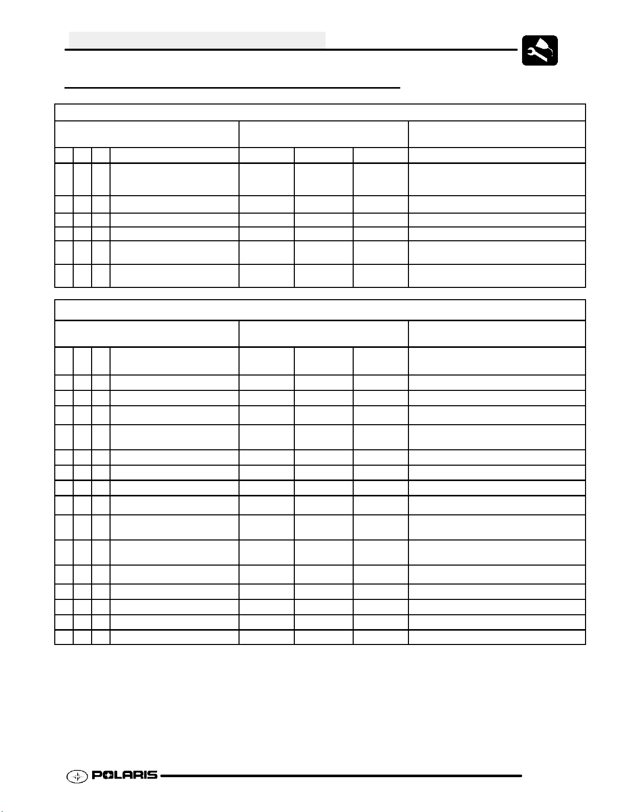
MODEL IDENTIFICATION
The machine model number must be used with any correspondence regarding warranty or service.
Machine Model Number Identification
A03GJ50AA
Emissions &
Year Designation
Basic Chassis
Designation Engine Designation
Model Option
ENGINE DESIGNATION NUMBER
ES50PLE01 Single, Water Cooled, Electric Start, Manual 5--Speed, DOHC 4 Stroke................
VIN IDENTIFICATION
World Mfg. ID
1 2 3 4 5 6 7 8 9 10 11 12 13 14 15 16 17
4XA GA
Body Style
Vehicle Descriptor
50A* 3P0 00 000
Engine
Powertrain
Emissions
Check Digit*
Model
Year
Plant No.*
Vehicle Identifier
Individual Serial No.
* This could be either
a number or a letter
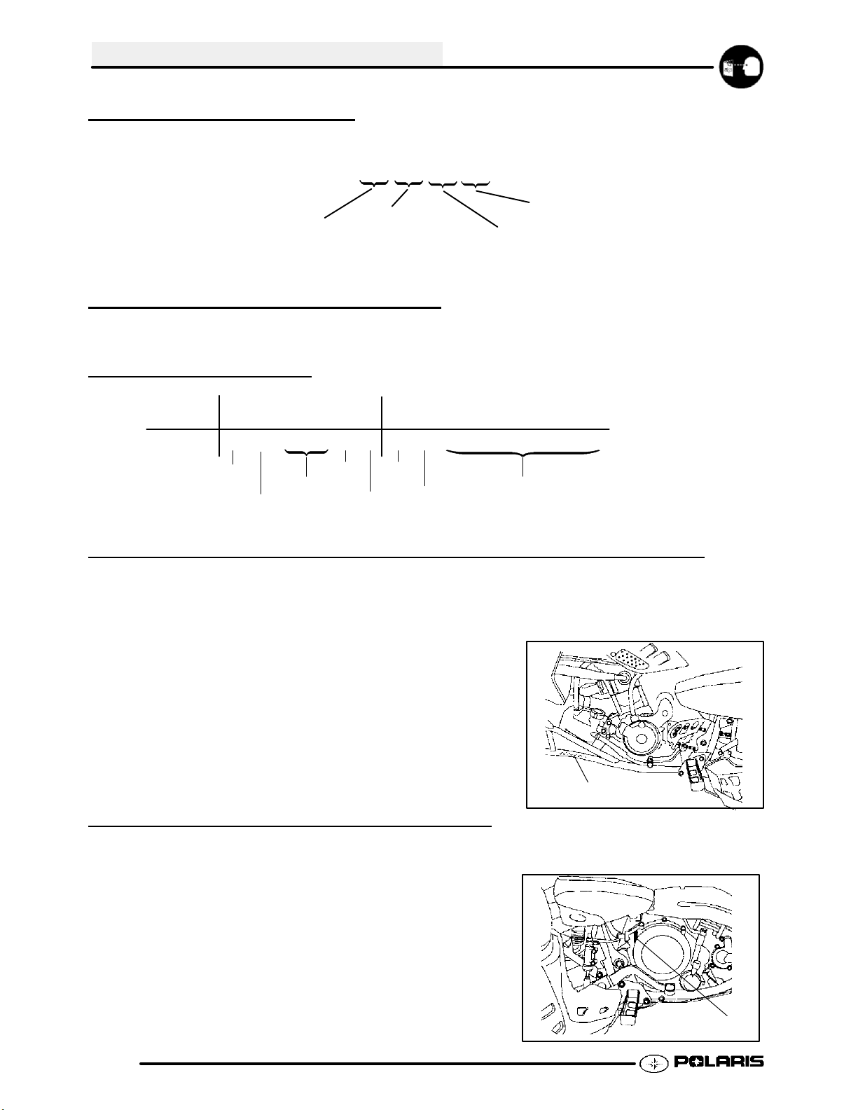
UNIT MODEL NUMBER AND SERIAL NUMBER LOCATION
Whenever corresponding with Polaris about a
particular issue, the machine model number and
serial number are important for vehicle
identification. The machine serial number is
stamped on the lower left side of the frame
tube.(B)
LH View
B
ENGINE SERIAL NUMBER LOCATION
This information can be found on the clutch housing
on the left side of engine.(A)
1.2
RH View
A
Page 8
PUBLICATION NUMBERS
PREDATORA03GJ50CA
GENERAL INFORMATION
Year Model Model No. Owner’s
Manual PN
2003
NOTE: When ordering service parts be sure to use the correct parts manual.
9917574 9917576 9917577
Parts
Manual PN
Parts
Micro Fiche PN
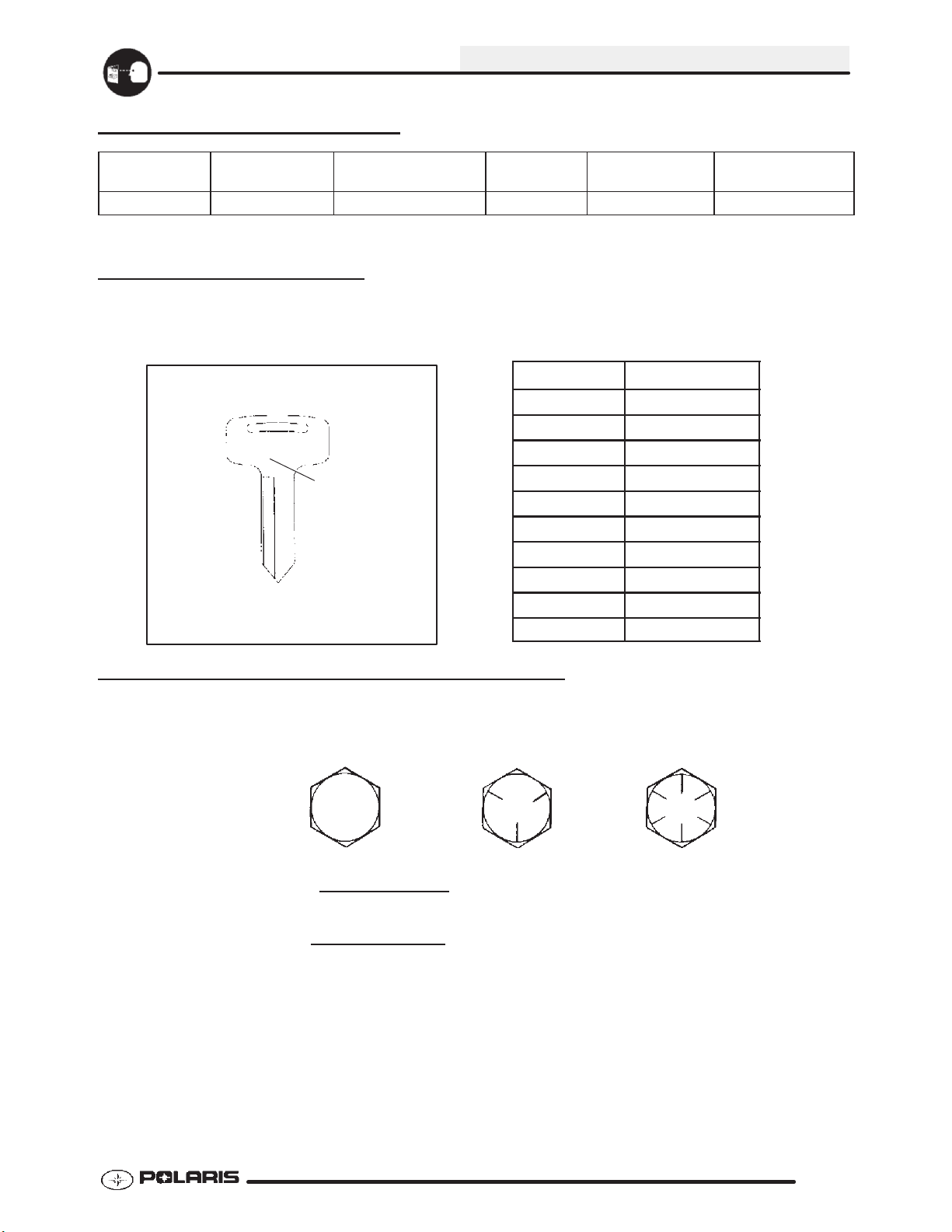
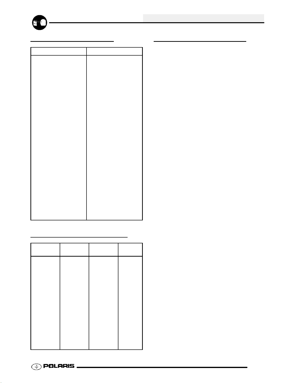
REPLACEMENT KEYS
Replacement keys can be made from the original key. To identify which series the key is, take the first two digits
on the original key and refer to the chart to the right for the proper part number. Should both keys become lost,
replacement of the ignition switch assembly is necessary.
Series # Part Number
20 4010278
21 4010278
31XX
Key Series
Number
22 4010321
23 4010321
27 4010321
28 4010321
31 4110141
32 4110148
67 4010278
68 4010278
STANDARD TORQUE SPECIFICATIONS
The following torque specifications are to be used as a general guideline. FOR SPECIFIC TORQUE VALUES OF
FASTENERS Refer to exploded views in the appropriate section. There are exceptions in the steering,
suspension, and engine sections.
Bolt Size Threads/In Grade 2 Grade 5 Grade 8
T orque in. lbs. (Nm)
#10 - 24 27 (3.1) 43 (5.0) 60 (6.9).............. ................ ..............
#10 - 32 31 (3.6) 49 (5.6) 68 (7.8).............. ................ ..............
Torque ft. lbs. (Nm)*
1/4 - 20 5 (7) 8 (11) 12 (16).............. .................. ................
1/4 - 28 6 (8) 10 (14) 14 (19).............. .................. ..............
5/16 - 18 11 (15) 17 (23) 25 (35).............. ................ ..............
5/16 - 24 12 (16) 19 (26) 29 (40).............. ................ ..............
3/8 - 16 20 (27) 30 (40) 45 (62).............. ................ ..............
3/8 - 24 23 (32) 35 (48) 50 (69).............. ................ ..............
7/16 - 14 30 (40) 50 (69) 70 (97).............. ................ ..............
7/16 - 20 35 (48) 55 (76) 80 (110).............. ................ ..............
1/2 - 13 50 (69) 75 (104) 110 (152).............. ................ .............
1/2 - 20 55 (76) 90 (124) 120 (166).............. ................ .............
Metric / Torque 6 x 1.0. 72-78 In. lbs. 8 x 1.25 14-18 ft. lbs 10 x 1.25 26-30 ft. lbs.
1.3
Page 9

GENERAL INFORMATION
PREDATOR MODELS
1.4
PREDATOR 500
TROY LEE LIMITED EDITION
PREDATOR 500
Page 10
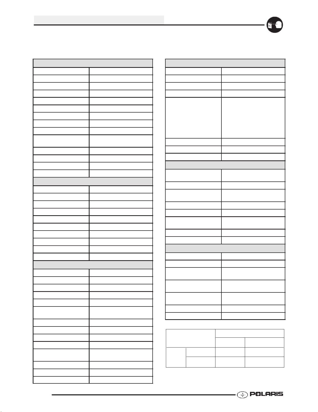
MODEL: 2003 PREDA TOR 500..........
MODEL NUMBER: A03GJ50AA.
ENGINE MODEL: ES50PLX..
GENERAL INFORMATION
Catagory
Length 71.5 in./182 cm
Width 47.5 in./121 cm
Height 45 in./114 cm
Seat Height 32 in./81.28 cm
Wheel Base 51 in./130 cm
Ground Clearance 4.5in./11cm
Dry Weight 415 lbs./188 kg
Fuel Capacity 3.25 gal./12.3 ltr
Oil Capacity 2.25 qts./2.1 ltr
Coolant Capacity 2.25 qts./2.1 ltr
Dimension
Dune PackageShown
1.5
Page 11
GENERAL INFORMATION
MODEL: 2003 PREDA TOR 500..........
MODEL NUMBER: A03GJ50AA.
ENGINE MODEL: ES50PLE01..
Engine
Platform Fuji DOHC 4 stroke
Engine Model Number ES50PLE01
Engine Displacement 499cc
Number of Cylinders 1
Bore & Stroke (mm) 99.2 x 64.6 mm
Compression Ratio 10.8:1
Compression Pressure 130 psi
Engine Idle Speed 1600 Rpm
Cooling System Liquid
Thermostat Opening
Temperature
Overheat Warning High Temp Light
Lubrication Pressurized Dry Sump
Oil Requirements PS--4 Synthetic
Exhaust System 2 to 1 canister style
Carburetion
Carburetor model Mikuni BSR 42mm
Main Jet 150
Pilot jet 45
Jet Needle 6CGY07-060-3
Needle Jet O-OM
Pilot Screw 2.5 Turns Out
Pilot Air Jet 110
Float Height 13--14 mm (0.51-- 0.55“)
Fuel Delivery Fuel Pump
Fuel Requirement 87 Octane (minimum)
Electrical
Alternator Output 200 w @ 3000 RPM
Voltage Regulator 3--Phase PN 4010654
Lghts : Main Headlights Dual Beam 35 watts / 35 watts
Tai l 8.26 watts
Brake 26.9 watts
Neutral / Hot
Indicator lights
Ignition System DC/CDI Ignition
RPM Limit 9005
Ignition Timing 30qr3q BTDC @ 3500 RPM
Spark plug / Gap NGK DCPR8E/ .035 in./0.9mm
Battery / Model / Amp Hr Maintenance--Free
Circuit Breakers Fan10amp/Harness20amp
Starting Electric -- Standard
Instrument Cluster N/A
160qF(71qC)
1 watt (ea.)
YuasaYTX99AmpHr
Drivetrain
Transmission Type Manual 5 speed
Main Sprocket -- # Tooth 14
Rear Sprocket -- # Tooth 37
Axle Runout -- Maximum .020” (.51 mm)
Gear Ratio : 1st
2nd
3rd
4th
5th
Primary
Chain Size / Deflection 520 O-- ring
Clutch Type Wet Multi Plate
Clutch Lever Freeplay 1/8s -3/16s / 3.1 - 4.7 mm
2.615
1.765
1.350
1.091
0.958
2.792
Steering / Suspension
Front Suspension
Style / Shock
Front Travel 10 in. / 25.4 cm
Rear Suspension
Style / Shock
Rear Travel 11 in. / 27.94 cm
Ground Clearance 4.5 in. / 11.43 cm
Shock Preload Adjustment
Front / Rear
Turning Radius 67 in. / 170.18 cm
Toe O u t 0 -- 1/16 in / .0 -- .159 cm
Dual A-- arm / Fox Shock
Linkless Swing Arm / Fox Shock
w/ remote reservoir
Front -- Spring tension -- Std.
Rear -- Fox Dual Clicker -- Std.
Wheels / Brakes
Wheel Size -- Front 21x7-- 10 Aluminum
Wheel Size -- Rear 20x11-- 10 Aluminum
Front Tire
Make / Model / Size
Rear Tire
Make / Model / Size
Recommended Air Pressure
F/R
Brake -- Front Dual Hydraulic Disc
Brake -- Rear Single Hydraulic Disc
Maxxis Razr 21x7-- 10
Maxxis Razr 20x11--10
5 psi Front
5 psi Rear
JETTING CHART
AMBIENT TEMPERATURE
Altitude
Meters
(Feet)
0--1800
(0--6000)
above 1800
(above 6000)
Below 40qF
Below 5qC
155 150
147.5
+40qFto+80qF
+5qCto+28qC
142.5
1.6
Page 12
GENERAL INFORMATION
SAE TAP DRILL SIZES
Thread Size/Drill Size Thread Size/Drill Size
#0-80 3/64
#1-64 53
#1-72 53
#2-56 51
#2-64 50
#3-48 5/64
#3-56 45
#4-40 43
#4-48 42
#5-40 38
#5-44 37
#6-32 36
#6-40 33
#8-32 29
#8-36 29
#10-24 24
#10-32 21
#12-24 17
#12-28 4.6mm
1/4-20 7
1/4-28 3
5/16-18 F
5/16-24 I
3/8-16 O
3/8-24 Q
7/16-14 U
7/16-20 25/64
1/2-13 27/64
1/2-20 29/64
9/16-12 31/64
9/16-18 33/64
5/8-11 17/32
5/8-18 37/64
3/4-10 21/32
3/4-16 11/16
7/8-9 49/64
7/8-14 13/16
1-8 7/8
1-12 59/64
1 1/8-7 63/64
1 1/8-12 1 3/64
11/4-7 17/64
1 1/4-12 1 11/64
11/2-6 111/32
1 1/2-12 1 27/64
13/4-5 19/16
1 3/4-12 1 43/64
2-4 1/2 1 25/32
2-12 1 59/64
2 1/4-4 1/2 2 1/32
21/2-4 21/4
23/4-4 21/2
3-4 2 3/4
METRIC TAP DRILL SIZES
Tap Size Drill Size Decimal
Equivalent
3x.50
3x.60
4x.70
4x.75
5x.80
5x.90
6 x 1.00
7 x 1.00
8 x 1.00
8 x 1.25
9 x 1.00
9 x 1.25
10 x 1.25
10 x 1.50
11 x 1.50
12 x 1.50
12 x 1.75
#39
3/32
#30
1/8
#19
#20
#9
16/64
J
17/64
5/16
5/16
11/32
R
3/8
13/32
13/32
0.0995
0.0937
0.1285
0.125
0.166
0.161
0.196
0.234
0.277
0.265
0.3125
0.3125
0.3437
0.339
0.375
0.406
0.406
Nearest
Fraction
3/32
3/32
1/8
1/8
11/64
5/32
13/64
15/64
9/32
17/64
5/16
5/16
11/32
11/32
3/8
13/32
13/32
DECIMAL EQUIVALENTS
1/64 .0156................
1/32 .0312 1 mm = .0394s........... ...
3/64 .0469................
1/16 .0625...........
5/64 .0781 2 mm = .0787s................ ...
3/32 .0938...........
7/64 .1094 3 mm = .1181s.............. ...
1/8. .1250...
9/64 .1406................
5/32 .1563 4 mm = .1575s........... ...
11/64 .1719...............
3/16 .1875 5 mm = .1969s........... ...
13/64 .2031...............
7/32 .2188...........
15/64 .2344 6 mm = .2362s............... ...
1/4 .25....
17/64 .2656 7 mm = .2756s............... ...
9/32 .2813...........
19/64 .2969...............
5/16 .3125 8 mm = .3150s........... ...
21/64 .3281...............
11/32 .3438 9 mm = .3543s.......... ...
23/64 .3594...............
3/8 .375....
25/64 .3906 10 mm = .3937s............... ...
13/32 .4063.........
27/64 .4219 11 mm = .4331s............... ...
7/16 .4375...........
29/64 .4531...............
15/32 .4688 12 mm = .4724s......... ...
31/64 .4844...............
1/2 .5 13 mm = .5118.... ..............
33/64 .5156...............
17/32 .5313.........
35/64 .5469 14 mm = .5512s............... ...
9/16 .5625...........
37/64 .5781 15 mm = .5906s............... ...
19/32 .5938.........
39/64 .6094...............
5/8 .625 16 mm = .6299s.... ............
41/64 .6406...............
21/32 .6563 17 mm = .6693s......... ...
43/64 .6719..............
11/16 .6875..........
45/64 .7031 18 mm = .7087s............... ...
23/32 .7188.........
47/64 .7344 19 mm = .7480s............... ...
3/4 .75....
49/64 .7656...............
25/32 .7813 20 mm = .7874s......... ...
51/64 .7969...............
13/16 .8125 21 mm = .8268s......... ...
53/64 .8281...............
27/32 .8438.........
55/64 .8594 22 mm = .8661s............... ...
7/8 .875....
57/64 .8906 23 mm = .9055s............... ...
29/32 .9063.........
59/64 .9219..............
15/16 .9375 24 mm = .9449s......... ...
61/64 .9531...............
31/32 .9688 25 mm = .9843......... ...
63/64 .9844...............
11.0.....
1.7
Page 13
GENERAL INFORMATION
CONVERSION TABLE
Unit of Measure Multiplied by Converts to
ft. lbs. x12 =in.lbs.
in. lbs. x .0833 = ft. lbs.
ft. lbs. x1.356 =Nm
in. lbs. x .0115 =kg-m
Nm x .7376 = ft. lbs.
kg-m x7.233 = ft. lbs.
kg-m x 86.796 =in.lbs.
kg-m x9.807 =Nm
in. x25.4 =mm
mm x .03937 =in.
in. x2.54 =cm
mile (mi.) x1.6 =km
km x .6214 = mile (mi.)
Ounces (oz) x 28.35 = Grams (g)
Fluid Ounces (fl. oz.) x 29.57 = Cubic Centimeters (cc)
Cubic Centimeters (cc) x .03381 = Fluid Ounces (fl. oz.)
Grams (g) x0.035 = Ounces (oz)
lb. x.454 =kg
kg x 2.2046 =lb.
Cubic inches (cu in) x 16.387 = Cubic centimeters (cc)
Cubic centimeters (cc) x0.061 = Cubic inches (cu in)
Imperial pints (Imp pt) x0.568 = Liters (l)
Liters (l) x1.76 = Imperial pints (Imp pt)
Imperial quarts (Imp qt) x1.137 = Liters (l)
Liters (l) x0.88 = Imperial quarts (Imp qt)
Imperial quarts (Imp qt) x1.201 =USquarts(USqt)
US quarts (US qt) x0.833 = Imperial quarts (Imp qt)
US quarts (US qt) x0.946 = Liters (l)
Liters (l) x1.057 =USquarts(USqt)
US gallons (US gal) x3.785 =Liters (l)
Liters (l) x0.264 = US gallons (US gal)
Pounds - force per square inch (psi) x6.895 = Kilopascals (kPa)
Kilopascals (kPa) x0.145 = Pounds - force per square inch (psi)
Kilopascals (kPa) x0.01 = Kilograms - force per square cm
Kilograms - force per square cm x98.1 = Kilopascals (kPa)
S xR2x H (height) = Cylinder Volume
qCtoqF: 9 (qC + 40) y 5-40=qF
qFtoqC: 5 (qF+40)y 9-40=qC
1.8
Page 14
GENERAL INFORMATION
GLOSSARY OF TERMS
ABDC: After bottom dead center.
ACV: Alternating current voltage.
Alternator: Electrical generator producing voltage alternating current.
ATDC: After top dead center.
BBDC: Before bottom dead center.
BDC: Bottom dead center.
BTDC: Before top dead center.
CC: Cubic centimeters.
Center Distance: Distance between center of crankshaft and center of driven clutch shaft.
Chain Pitch: Distance between chain link pins (No. 35 = 3/8s or 1 cm). Polaris measures chain length in number of pitches.
CI: Cubic inches.
Clutch Buttons: Plastic bushings which aid rotation of the movable sheave in the drive and driven clutch.
Clutch Offset: Drive and driven clutches are offset so that drive belt will stay nearly straight as it moves along the clutch face.
Clutch Weights: Three levers in the drive clutch which relative to their weight, profile and engine RPM cause the drive
clutch to close and grip the drive belt.
Crankshaft Run-Out: Run-out or “bend” of crankshaft measured with a dial indicator while crankshaft is supported
between centers on V blocks or resting in crankcase. Measure at various points especially at PTO.
DCV: Direct current voltage.
Dial Bore Gauge: A cylinder measuring instrument which uses a dial indicator. Good for showing taper and
out-of-round in the cylinder bore.
Electrical Open: Open circuit. An electrical circuit which isn’t complete.
Electrical Short: Short circuit. An electrical circuit which is completed before the current reaches the intended load.
(i.e. a bare wire touching the chassis).
End Seals: Rubber seals at each end of the crankshaft.
Engagement RPM: Engine RPM at which the drive clutch engages to make contact with the drive belt.
ft.: Foot/feet.
Foot Pound: Ft. lb. A force of one pound at the end of a lever one foot in length, applied in a rotational direction.
g: Gram. Unit of weight in the metric system.
gal.: Gallon.
ID: Inside diameter.
in.: Inch/inches.
Inch Pound: In. lb. 12 in. lbs. = 1 ft. lb.
kg/cm2: Kilograms per square centimeter.
kg-m: Kilogram meters.
Kilogram/meter: A force of one kilogram at the end of a lever one meter in length, applied in a rotational direction.
lorltr: Liter.
lbs/in2: Pounds per square inch.
Left or Right Side: Always referred to based on normal operating position of the driver.
m: Meter/meters.
Mag: Magneto.
Magnetic Induction: As a conductor (coil) is moved through a magnetic field, a voltage will be generated in the
windings. Mechanical energy is converted to electrical energy in the stator.
mi.: Mile/miles.
mm: Millimeter. Unit of length in the metric system. 1mm = approximately .040s.
Nm: Newton meters.
OD: Outside diameter.
Ohm: The unit of electrical resistance opposing current flow.
oz.: Ounce/ounces.
Piston Clearance: Total distance between piston and cylinder wall.
psi.: Pounds per square inch.
PTO: Power take off.
PVT: Polaris Variable Transmission (Drive Clutch System)
qt.: Quart/quarts.
Regulator: Voltage regulator. Regulates battery charging system output at approx. 14.5 DCV as engine RPM increases.
Reservoir Tank: The fill tank in the liquid cooling system.
Resistance: In the mechanical sense, friction or load. In the electrical sense, ohms, resulting in energy conversion to heat.
RPM: Revolutions per minute.
SeizedPiston: Galling of the sides of a piston. Usually there is a transfer of aluminum from the piston onto the cylinder wall.
Possible causes: 1) improper lubrication; 2) excessive temperatures; 3) insufficient piston clearance; 4) stuck piston rings.
Stator Plate: The plate mounted under the flywheel supporting the battery charging coils.
TDC: Top dead center. Piston’s most outward travel from crankshaft.
Vol t: The unit of measure for electrical pressure of electromotive force. Measured by a voltmeter in parallel with the circuit.
Watt: Unit of electrical power. Watts = amperes x volts.
WOT: Wide open throttle.
1.9
Page 15
GENERAL INFORMATION
NOTES
1.10
Page 16
MAINTENANCE
CHAPTER 2 MAINTENANCE
Periodic Maintenance Chart 2.2-2.3...............
Pre-Ride Inspection 2.4......................
Lubricant and Maintenance Product Numbers 2.5
Special Tools 2.6............................
Lubrication Charts 2.7-2.8........................
Clutch Freeplay Adjustment 2.9...............
Throttle Inspection 2.9.......................
Carburetor Adjustments 2.9-2.10...................
Throttle Adjustment 2.10-2.11.......................
Fuel System 2.11-2.12.............................
2
Compression Test 2.12........................
Spark Plug Maintenance 2.13..................
Battery Maintenance 2.13--2.14......................
Electrical 2.14-2.15................................
Coolant System Maintenance 2.15-2.16..............
Radiator Screen Removal 2.17.................
Air Filter Service 2.17.........................
Air Box Sediment Tube Service 2.17............
Crankcase Breather Filter 2.18.................
Oil Change/Filter 2.18.........................
Steering and Toe Alignment 2.19-2.20...............
Exhaust System Maintenance 2.21.............
Brake System Service 2.22-2.23....................
Suspension Adjustment 2.23-2.26...................
Controls / Handlebar Adjustment 2.26...........
Wheel Removal/Installation 2.26................
Tire Inspection 2.27...........................
2.1
Page 17
MAINTENANCE
PERIODIC MAINTENANCE CHART
Inspection, adjustment and lubrication intervals of important components are listed in the following chart.
Maintenance intervals are based upon average riding conditions and vehicle speed.
The following symbols denote potential items to be aware of during maintenance:
H= CAUTION: Due to the nature of these adjustments, it is recommended this service be performed
by an authorized Polaris dealer.
"= SEVERE USE ITEM -- --If vehicle is subjected to severe use, decrease interval by 50% (Severe Use is defined
as frequent vehicle immersion in mud, water or sand, racing or race- style high rpm use, manual slipping of the clutch
prolonged low speed - heavy load operation or extended idle. More preventati ve maintenance is required under these
conditions. Fluid changes, cable, chain and chassis lubri cat i on are required more frequently. For engine oil, short trip cold
weather riding also constitutes severe use. Pay special attention to oil level. A rising oil level in cold weather can indicate
contaminants collecting in the oil sump or crankcase. Change oil immediately and monitor level. If oil level begins to rise,
discontinue use and determine cause.
E= Emission Control System Service (California).
NOTE: Inspection may reveal the need for replacement parts. Always use genuine Polaris parts.
ENGINE / COOLING / CONTROLS
Item Maintenance Interval
(Whichever comes first)
Hours Calendar Miles
(Km)
"
"
"
"
" Air Box Sediment Tube -- Daily -- Drain deposits whenever visible
" Engine Breather Filter 20 hrs Monthly 200 (320) Inspect and clean if necessary
H
H
" Radiator 100 hrs 12 months 1000 (1600) Inspect / Clean external surfaces
" Cooling and Oil System Hoses 100 hrs 12 months 1000 (1600) Pre--ride / Inspect for leaks
" Engine Mounts 100 hrs 12 months 1000 (1600) Pre-- ride / Inspect
Engine Oil - Level/Change 10 hrs -- 100 (160) Check level pre-- ride
E
Oil Filter 10 hrs -- 100 (160) Replace with oil change
E
Air Filter - Pre-Filter Daily Daily -- Inspect, clean more often
E
Air Filter - Main Element Weekly Weekly -- Inspect - Replace if necessary
E
Idle Speed As required As required -- Adjust as required
E
Throttle Cable / ETC Switch 50 hrs 6months 500 (800) Inspect -Adjust, Lubricate, Replace if necessary
Choke (Enricher) Cable 50 hrs 6months 500 (800) Inspect -Adjust, Lubricate, Replace if necessary
Carburetor Float Bowl 50 hrs 6months 500 (800) Drain bowl periodically and prior to storage
Carburetor Air Intake Ducts/Flange 50 hrs 6months 500 (800) Inspect all ducts for proper sealing/air leaks
Fuel System 100 hrs 12 months 1000 (1600) Check for leaks at tank cap, lines, fuel valve, filter,
E
Coolant/Level Inspection Daily Daily Replace engine coolant every 2 years
Coolant Strength /
System Pressure Test
Exhaust Muffler / Pipe 100 hrs 12 months 1000 (1600) Pre--ride / Inspect
100 hrs 6months 1000 (1600) Inspect strength seasonally;
pump & carburetor. Replace lines every 2 years.
Pressure test system annually
Remarks
Break-- In service at 1 hour
in dirty or wet conditions
2.2
Page 18
MAINTENANCE
PERIODIC MAINTENANCE CHART CONT’D
ELECTRICAL
Item Maintenance Interval
(Whichever comes first)
Spark Plug 100 hrs 12 months 1000 (1600) Inspect - Replace if necessary
E
" Wiring 100 hrs 12 months 1000 (1600) Inspect for abrasion, routing, security.
H
" Battery 20 hrs Monthly 200 (320) Check terminals; Clean; Test
Ignition Timing 100 hrs 12 months 1000 (1600) Inspect
Headlight Aim As required As required -- Adjust as Necessary
Headlamp Inspection Daily Daily -- Check operation daily; Apply dielectric
Tail Lamp Inspection Daily Daily -- Check operation daily; Apply dielectric
Apply Dielectric grease to connectors that are
grease whenever lamp is replaced
grease whenever lamp is replaced
CHASSIS / SUSPENSION / BRAKE
Item Maintenance Interval
(Whichever comes first)
Hours Calendar Miles
(Km)
" General Lubrication 50 hrs 3months 500 (800) Lubricate All Fittings, Pivots, Cables, Etc.
Drive Chain Pre--ride Pre--ride Pre--ride Clean and Inspect, Adjust, Lubricate
H
H
" Front Suspension Pre--ride Pre--ride Pre--ride Inspect - Lubricate
" Rear Suspension Pre--ride Pre--ride Pre--ride Inspect - Lubricate
H
" Brake Fluid Level Pre-ride Pre-ride -- Inspect Sight Glass Daily
" Brake Lever Travel Pre-ride Pre-ride -- Inspect Daily
"
H
Steering Pre--ride Pre--ride Pre--ride Inspect Daily, Lubricate
Toe Adjustment As required As required -- Periodic Inspection, Adjust Whenever
Tires Pre-ride Pre-ride -- Inspect Daily, Pre-Ride Inspection Item
Brake Fluid 200 hrs 24 months 2000 (3200) Change Every Two Years
Brake Pad Wear 10 hrs Monthly 100 (160) Inspect Periodically
Brake Adjustment As required As required -- Inspect Deflection Daily; Adjust
Brake System Pre-ride Pre-ride -- Pre-Ride Inspection Item
Wheels / Fasteners Pre-ride Pre-ride -- Pre-Ride Inspection Item
Frame Nuts, Bolts, Fasteners Pre-ride Pre-ride -- Pre-Ride Inspection Item
Remarks
subjected to water, mud, etc.
Remarks
Parts are Replaced
Pre-Ride Inspection Item
Pre-Ride Inspection Item
2.3
Page 19
MAINTENANCE
PRE-RIDE / DAILY INSPECTION
Perform the following pre-ride inspection daily, and when servicing the vehicle at each scheduled maintenance.
G Tires - check condition and pressures
G Fuel and oil tanks - fill both tanks to their proper level; Do not overfill oil tank
G All brakes - check operation and adjustment (includes auxiliary brake)
G Throttle - check for free operation
G Headlight/Taillight/Brakelight - check operation of all indicator lights and switches
G Engine stop switch - check for proper function
G Wheels - check for loose wheel nuts and axle nuts; check to be sure axle nuts are secured by
cotter pins
G Air cleaner element - check for dirt or water; clean or replace
G Steering - check for free operation, noting any unusual looseness in any area
G Loose parts - visually inspect vehicle for any damaged or loose nuts, bolts or fasteners
G Engine coolant - check for proper level at the recovery bottle
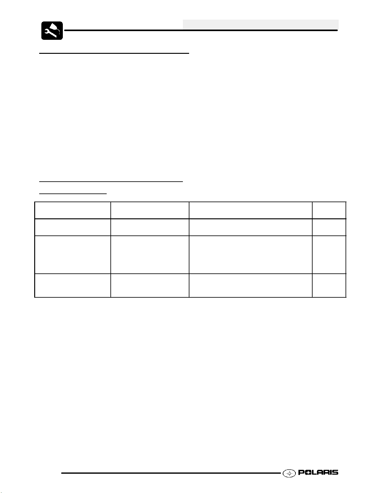
RECOMMENDED PRE--RIDE FLUID
LEVEL
Engine Oil / Transmission Polaris PS 4
Coolant / Level Polaris Premium 60/40
Brake Fluid Polaris DOT 3 Brake Fluid Fill to indicated level inside reservoir.
NOTE: Quick Reference Lubricants and maintenance product part numbers are listed on page 2.5
CHECKS
Item Type Notes See
Add to proper level on dipstick. 2.18
Synthetic
Allow engine and cooling system to cool
Pre-mixed Antifreeze/
Coolant or a 50/50 mixture
high quality antifreeze/
coolant and distilled water
completely and check level in radiator.
Fill to top of filler neck. If reservoir was
empty or extremely low, fill radiator be-
fore filling reservoir tank to full line.
Sight glass should appear dark when
installed, indicating proper fluid level.
Pages
2.15
2.22
2.4
Page 20
MAINTENANCE
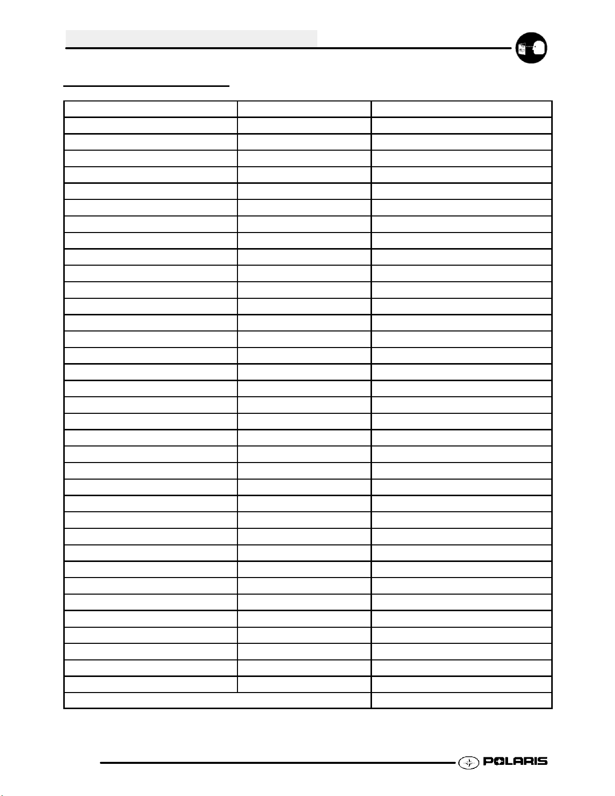
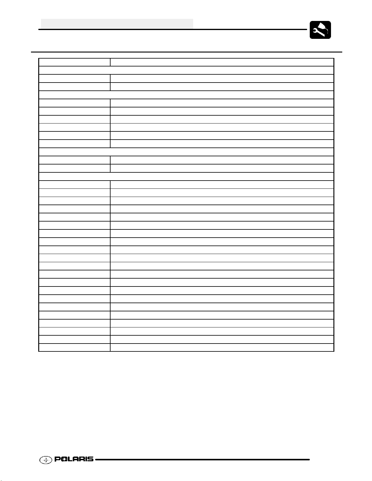
POLARIS LUBRICANTS,MAINTENANCE AND SERVICE PRODUCTS
Part No. Description
Engine Lubricant
2874414 Engine Oil (Quart) PS 4 Synthetic (4-- Cycle)
2874415 Engine Oil (Gallon) PS 4 Synthetic (4--Cycle)
Grease / Specialized Lubricants
2871322 Premium All Season Grease (3 oz. cartridge)
2871423 Premium All Season Grease (14 oz. cartridge)
2871460 Starter Drive Grease
2871312 Grease Gun Kit
2871329 Dielectric Grease
2872073 Chain Lube (Aerosol)
Coolant
2871323 60/40 Coolant (Gallon)
2871534 60/40 Coolant (Quart)
Additives / Sealants / Thread Locking Agents / Misc.
2870791 Fogging Oil (12 oz. Aerosol)
2871326 Premium Carbon Clean (12 oz.)
2870652 Fuel Stabilizer (16 oz.)
2870585 Loctitet Primer N, Aerosol, 25 g
2870990 DOT3 Brake Fluid
2871956 Loctitet Thread Sealant 565 (50 ml.)
2871949 Loctitet Threadlock 242 (50 ml.)
2871950 Loctitet Threadlock 242 (6 ml.)
2871951 Loctitet Threadlock 262 (50 ml.)
2871952 Loctitet Threadlock 262 (6 ml.)
2871953 Loctitet Threadlock 271 (6 ml.)
2871954 Loctitet Threadlock 271 (36 ml.)
2870584 Loctitet RC 680-Retaining Compound (10 ml.)
2870587 Loctitet 518 Gasket Eliminator / Flange Sealant (50 ml.)
2872113 Disk Brake Quiet (12 oz.)
2872113 Disc Brake Quiet, Aerosol, (9 oz.)
2871957 Black RTV Silicone Sealer (3 oz. tube)
2871958 Black RTV Silicone Sealer (11 oz. cartridge)
8560054 Marine Grade Silicone Sealer (14 oz. cartridge)
2871557 Crankcase Sealant, 3-Bond 1215
2872893 Engine Degreaser
2.5
Page 21
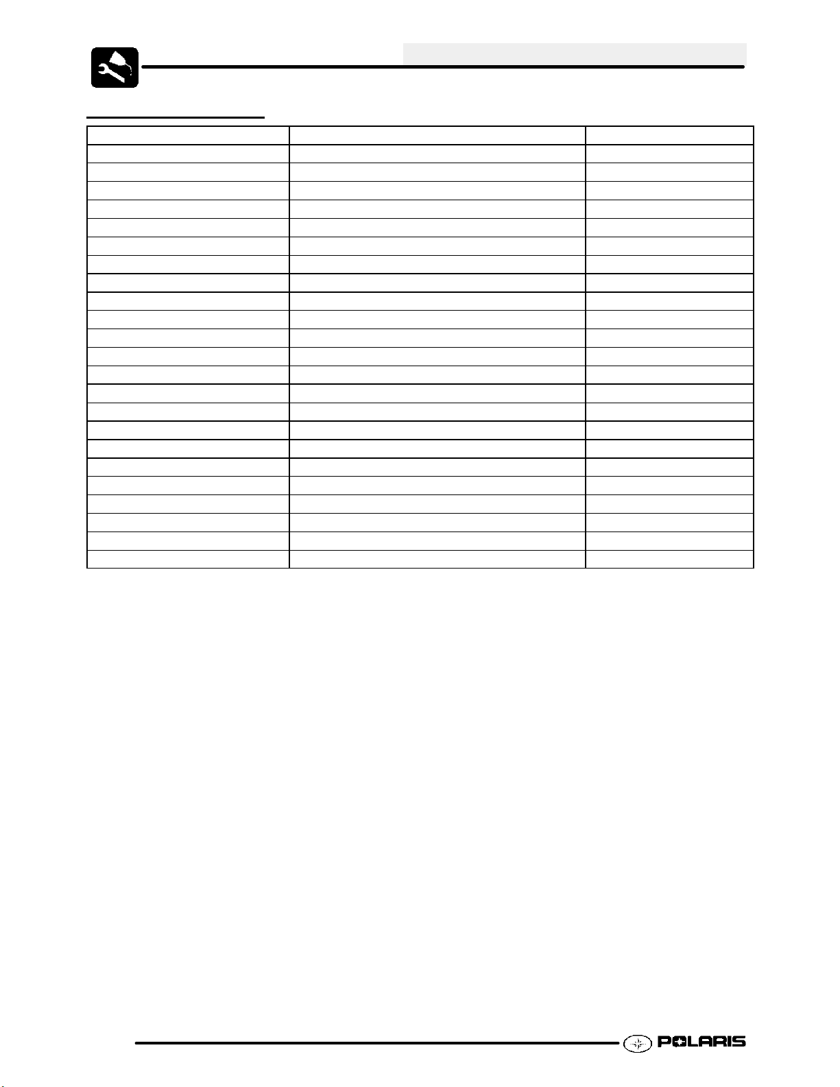
SPECIAL TOOLS
PART NUMBER TOOL DESCRIPTION CHAPTER TOOL USED IN
8712100 or 8712500 Tachometer 2,7
2200634 Valve Seat Reconditioning Kit 3
PU--45257 Valve Spring Compressor 3
PA-- 46075 Flywheel Puller 3
PA-- 46087 Crankcase Separator 3
2870390 Piston Support Block 3
2872105 Water Pump Mechanical Seal Puller 3
PA-- 45958 Cam Chain Tensioner Assembly Tool 3
PA-- 46076 MAG End Crankshaft Nut Remover/Installer 3
PA-- 46077 MAG End Crankshaft Installer 3
2871283 Crankshaft/Water Pump Seal Install Kit 3
5131135 Water Pump Install Kit 3
PA-- 46502 Valve Spring Compressor 3
2870975 Mity Vact Pressure Test Tool 3, 4
2872314 Carburetor Float Adjustment Tool 4
2870623 Shock Absorber Spring Compression Tool 5
7052069 Charging Needle 5
2200421 Gas Shock Recharging Kit 5
2871352 Shock Rod Holding Tool 5
2871351 Foxt Shock IFP Depth Tool 5
2870386 Piston Pin Puller 6
PV--43568 Fluket77 Digital Multimeter 7
2870630 Timing Light 7
*Special Tools Can be ordered through a Polaris Dealer or SPX Corporation (1--800--328--6657).
MAINTENANCE
2.6
Page 22
MAINTENANCE
LUBRICATION
1. Engine Oil and Filter ¡
2. Brake Fluid ©
(Right hand and Foot
Brake Master Cylinder)
3. Rear Drive Chain
Ill.
#
1. Engine Oil /
2. Brake Fluid Polaris
3 Drive Chain Polaris Chain Lube Apply to chain link plates and rollers. As required*
Item Lube Rec. Method Frequency*
Transmission
Polaris PS--4
Synthetic
Dot 3 Brake Fluid
Check dipstick and add to
proper level.
Fill master cylinder reservoir to in-
dicated level inside reservoir.
See Ch. 6.
Perform break-in oil/filter change at one
hour; change oil every 10hrs/100mi.¡
As required. Change fluid every
2 years or 200 hours.©
* More often under severe use, such as operation in mud, water, sand or under severe loads.
¡ Every 10 hours of operation (refer to Maintenance Schedule for additional information) Change more
often in extremely dirty conditions (continuous operation in water, mud or sand), continuous hot, cold, or short
trip cold weather operation. NOTE: Excessive clutch plate residue will accelerate oil change intervals
© Every 24 months or 200 hours of operation (refer to Maintenance Schedule for additional information)
More often under severe conditions (continuous operation in water, mud or sand)
2.7
Page 23
LUBRICATION, CONT.
8. Upper Steering Post Bushing
7. Rear Axle Eccentric
MAINTENANCE
5. Upper Control Arm
6. Lower Control Arm
Ill.
#
5. Upper Control Arms Polaris All Season
6. Lower Control Arms Polaris All Season
7. Rear Axle Eccentric Polaris All Season
8. Upper Steering Post Bushing Polaris All Season
Item Lube Rec. Method Frequency*
Grease¢
Grease¢
Grease¢
Grease¢
Locate fittings and grease
(also grease after washing ATV)
Locate fittings and grease
(also grease after washing ATV)
Locate and grease
(also grease after washing ATV)
Locate fittings and grease
(also grease after washing ATV)
Every 3 months ¡
Every 3 months ¡
Every 3 months ¡
Semi-annually ©
* More often under severe use, such as operation in water or under severe loads.
¡ Every 3 months or 50 hours of operation (refer to Maintenance Schedule for additional information)
More often under severe conditions (continuous operation in water, mud or sand)
© Every 6 months or 50 hours of operation (refer to Maintenance Schedule for additional information)
More often under severe conditions (continuous operation in water, mud or sand)
¢ Use grease conforming to NLGI No. 2, such as Polaris Premium All Season Grease.
2.8
Page 24
MAINTENANCE
CLUTCH ADJUSTMENT
Clutch Lever Freeplay
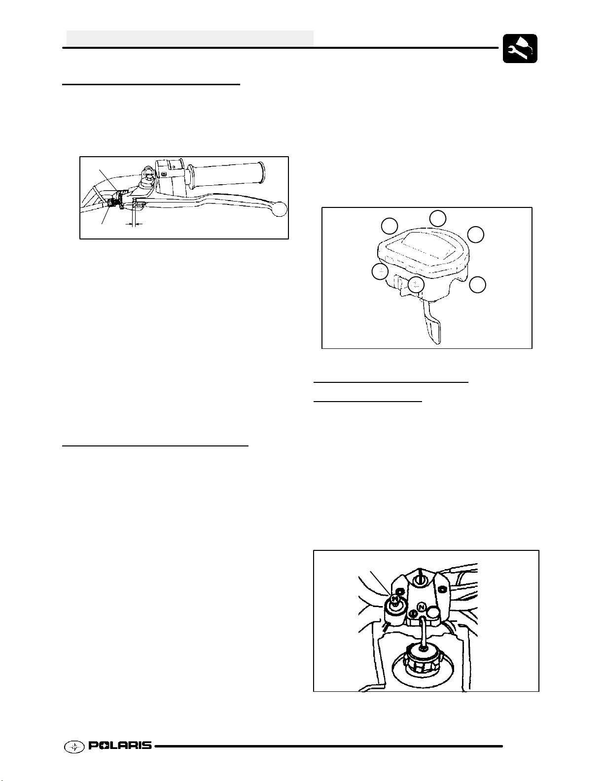
1. Measure clutch lever freeplay between the perch
and the lever (A). This distance should be 1/8s -
3/16s (3.1 mm - 4.7 mm).
C
B
2. If adjustment is required, slide the clutch perch
pivot boot down the clutch cable to access the
clutch adjustment screw (B) and lock ring (C).
3. Loosen the lock ring and turn the screw in
(clockwise) to increase lever travel. Turn the
screw out (counterclockwise) to decrease lever
travel. Tighten the lock ring.
4. Squeeze the lever fully and release. Slightly
squeeze the lever again until a slight resistance is
felt. Measure the freeplay again. If necessary,
repeat the adjustment procedure until proper
freeplay is attained.
5. Replace the clutch perch pivot boot over the
screw and lock ring.
A
THROTTLE INSPECTION
Check for smooth throttle opening and closing in all
handlebar positions. Throttle lever operation should
be smooth and lever must return freely without
binding.
1. Place the gear selector in neutral.
2. Set parking brake.
3. Start the engine and let it idle.
4. Turn handlebars from full right to full left. If idle
speed increases at any point in the turning range,
inspect throttle cable routing and condition.
Adjust cable tension as needed until lock--to--lock
turning can be accomplished with no rise in
engine rpm.
5. Replace the throttle cable if worn, kinked, or
damaged.
6. Inspect ETC cover seal and switch cavity by
removing the cover. Verify that no dirt, water or
mud is present.
To remove the ETC cover:
1. Use a medium flat blade screwdriver and insert
blade into the pocket of the cover starting on the
#1 position.
2. Twist screwdriver slightly while lifting on the cover
to release snap.
3. Repeat procedure at the other five locations as
shown.
NOTE: Do not attempt to remove cover until all
latch points are released.
2
1
5
5
4
ETC Cover
Removal Sequence
Ill. 1
3
6
6
CHOKE (ENRICHER)
ADJUSTMENT
If the choke knob does not stay out when pulled,
adjust the choke tension by tightening (clockwise) the
jam nut under the rubber boot between the choke
knob and nut. Firmly grasp the rubber boot and
tighten until the choke slides freely but stays out when
pulled.
Verify free play of 1/16--3/16” (1.6--4.76 mm) and
smooth operation of choke cable.
If smooth choke operation is not obtainable, inspect
choke cable for kinks or sharp bends in routing.
Choke
2.9
Page 25
MAINTENANCE
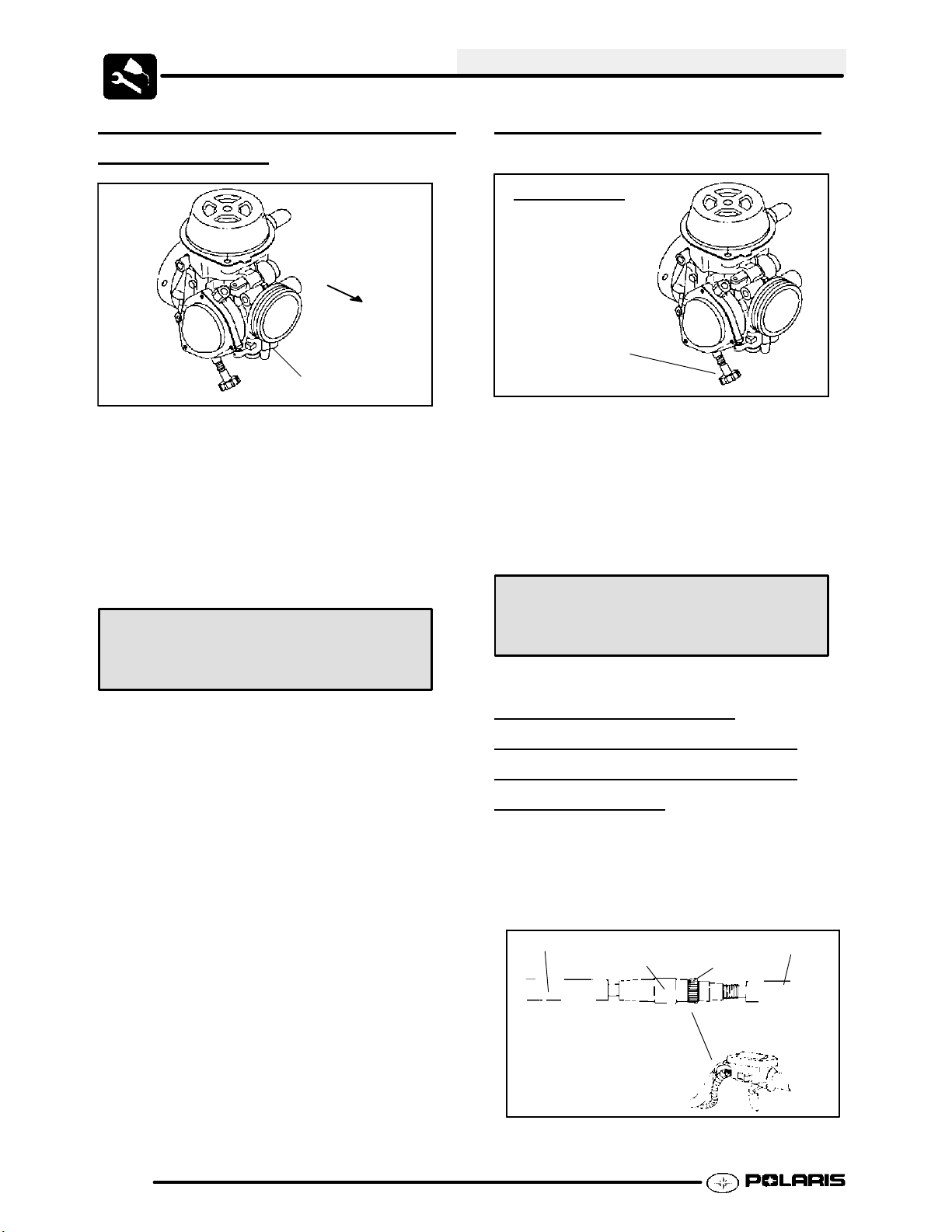
CARBURETOR PILOT SCREW
ADJUSTMENT
FRONT
(Engine)
Ill.2
NOTE: Pilot screw is covered by a welsh plug. Plug
removal will be required to perform these procedures.
1. Start engine and warm it up to operating
temperature (about 10 minutes).
2. Turn pilot screw in (clockwise) until lightly seated.
Turn screw out the specified number of turns.
NOTE: Do not tighten the pilot screw forcefully
against the seat or the screw and/or seat will be
permanently damaged. (Ill. 2)
Pilot Screw
IDLE SPEED ADJUSTMENT
BSR Carburetor
Idle Screw
Ill.3
1. Start engine and warm it up thoroughly.
2. Adjust idle speed by turning the idle adjustment
screw in (clockwise) to increase or out
(counterclockwise) to decrease RPM. (Ill.3)
NOTE: Adjusting the idle speed affects throttle cable
freeplay and electronic throttle control (ETC)
adjustment. Always check throttle cable freeplay
after adjusting idle speed and adjust if necessary.
Idle Speed:
Pilot Screw Adjustment
Refer to Specifications in Chapter 1
3. Connect an accurate tachometer that will read in
increments of + or -- 50 RPM such as the PET
2100DX (PN 8712100DX)orthePET2500(PN
8712500).
4. Set idle speed to 1600 RPM. Always check
throttle cable freeplay after adjusting idle speed
and adjust if necessary.
5. Slowly turn mixture screw clockwise using the
pilot screw wrench until engine begins to miss.
6. Slowly turn mixture screw counterclockwise until
idle speed increases to maximum RPM.
Continue turning counterclockwise until idle RPM
begins to drop.
7. Center the pilot screw between the points in Step
5 and 6.
8. Re adjust idle speed to specification.
1600 +/-- 50 RPM
THROTTLE CABLE /
ELECTRONIC
CONTROL (ETC
THROTTLE
SWITCH)
ADJUSTMENT
1. Slide boot off throttle cable adjuster and jam nut.
2. Place shift selector in neutral and set parking
brake.
3. Start engine and set idle to 1600 RPM.
Boot
Adjuster
Sleeve
Locknut
Boot
2.10
Ill. 1
Page 26
MAINTENANCE
NOTE: Be sure the engine is at operating
temperature. See Idle Speed Adjustment.
4. Loosen lock nut on in-line cable adjuster (Ill. 1).
5. Turn adjuster until 1/16s to 1/8s freeplay is
achieved at thumb lever. (Ill. 2). After making
adjustments, quickly actuate the thumb lever
several times and reverify freeplay.
Direction
of travel
Ill. 2
6. Tighten lock nut securely and slide boot
completely in place to ensure a water-tight seal.
7. Turn handlebars from left to right through the
entire turning range. If idle speed increases,
check for proper cable routing. If cable is routed
properly and in good condition, repeat adjustment
procedure.
1/16s -1/8s
Freeplay
loss of consciousness or death in a
short time.
G Never drain the float bowl when the
engine is hot. Severe burns may
result.
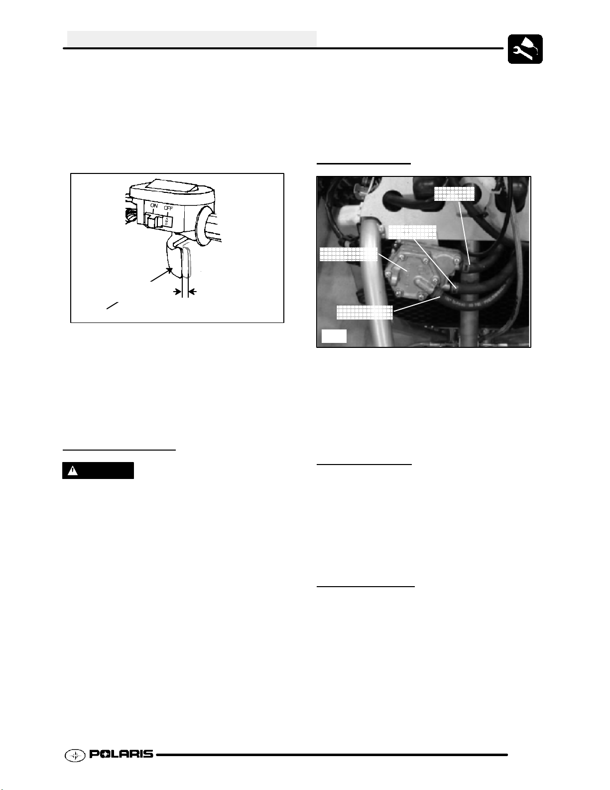
FUEL LINES
Fuel In
Fuel Out
Fuel Pump
Pulse Line
Ill.1
1. Check fuel lines for signs of wear, deterioration,
damage or leakage. Replace if necessary.
2. Be sure fuel lines are routed properly and secured
with cable ties. CAUTION: Make sure lines are
not kinked or pinched.
3. Replace all fuel lines every two years.
FUEL SYSTEM
WARNING
Gasoline is extremely flammable and explosive
under certain conditions.
G Always stop the engine and refuel
outdoors or in a well ventilated area.
G Do not smoke or allow open flames
or sparks in or near the area where
refueling is performed or where
gasoline is stored.
G Do not overfill the tank. Do not fill the
tank neck.
G If you get gasoline in your eyes or if
you swallow gasoline, seek medical
attention immediately.
G If you spill gasoline on your skin or
clothing, immediately wash it off with
soap and water and change clothing.
G Never start the engine or let it run in
an enclosed area. Engine exhaust
fumes are poisonous and can result
VENT LINES
Check engine, fuel tank, oil tank and carburetor vent
lines for signs of wear, deterioration, damage or
leakage. Replace every two years.
Be sure vent lines are routed properly and secured
with cable ties. CAUTION: Make sure lines are not
kinked or pinched.
FUEL VALVE
The Predator fuel system strains the fuel through
screens located in the fuel valve. There is no fuel filter
to service. To service the fuel valve:
1. Shut off fuel supply at fuel valve. Remove line
clamps and fuel lines from the tank.
2. Remove the tank and drain remainder of fuel into
a appropriate container.
3. Remove fuel valve by loosening the screws
holding the valve to the tank.
4. Inspect the valve for damage or debris. Replace
the valve if problems are found.
2.11
Page 27
MAINTENANCE
5. Reverse the procedures to install the fuel valve.
6. Start engine and inspect for leaks.
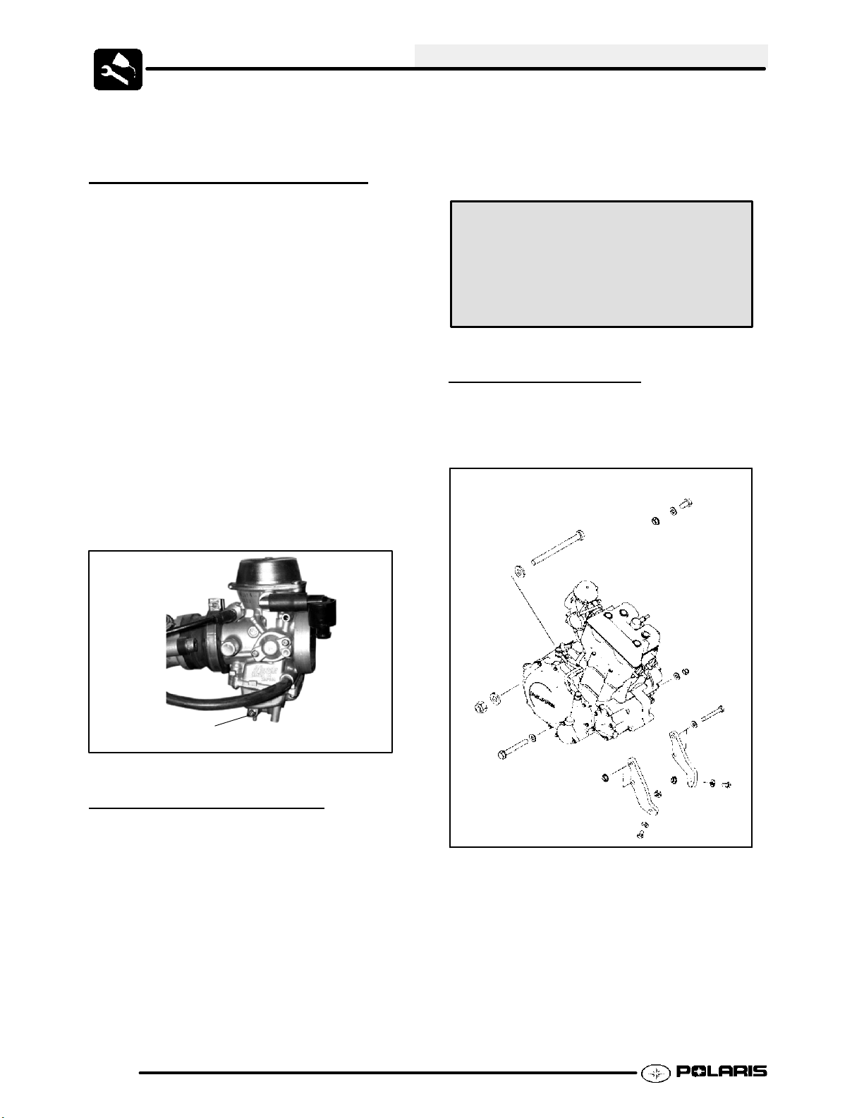
CARBURETOR DRAINING
The carburetor float bowl should be drained
periodically to remove moisture or sediment from the
bowl, or before extended periods of storage.
NOTE: The bowl drain screw is located on the bottom
left side of the float bowl.
1. Turn fuel valve to the off position.
2. Place a clean container beneath the bowl drain
spigot or bowl drain hose.
3. Turn drain screw out two turns and allow fuel in
the float bowl and fuel line to drain completely.
4. Inspect the drained fuel for water or sediment.
5. Tighten drain screw.
6. Turn fuel valve to “ON”.
7. Start machine and check for leaks.
NOTE: All tubes attached to the carburetor must be
check for pinching or blockage, as this will effect
engine performance.
A cylinder leakdown test is the best indication of
engine condition. Follow manufacturer’s instructions
to perform a cylinder leakage test. (Never use high
pressure leakage testers, as crankshaft seals may
dislodge and leak).
Cylinder Compression
w/ decompression
Standard: 85--90 PSI @ 400 RPM
Cylinder Leakdown
Service Limit 10 %
(Inspect for cause if leakage exceeds 10%)
ENGINE MOUNTS
Inspect engine mounts and frame for cracks or
damage. (Ill.3)
Check engine fasteners and ensure they are tight.
Drain Screw
Ill. 1
COMPRESSION TEST
NOTE: This engine has built--in decompression
components. Compression readings will vary in
proportion to cranking speed during the test. Average
compression (measured) is about 85--90 psi @ 400
RPM during a compression test.
A smooth idle generally indicates good compression.
Low engine compression is rarely a factor in running
condition problems above idle speed. Abnormally
high compression can be caused by carbon deposits
in the combustion chamber or worn, damaged
exhaust cam lobes. Inspect camshaft and
combustion chamber if compression is abnormally
high.
2.12
Ill. 3
Page 28
MAINTENANCE
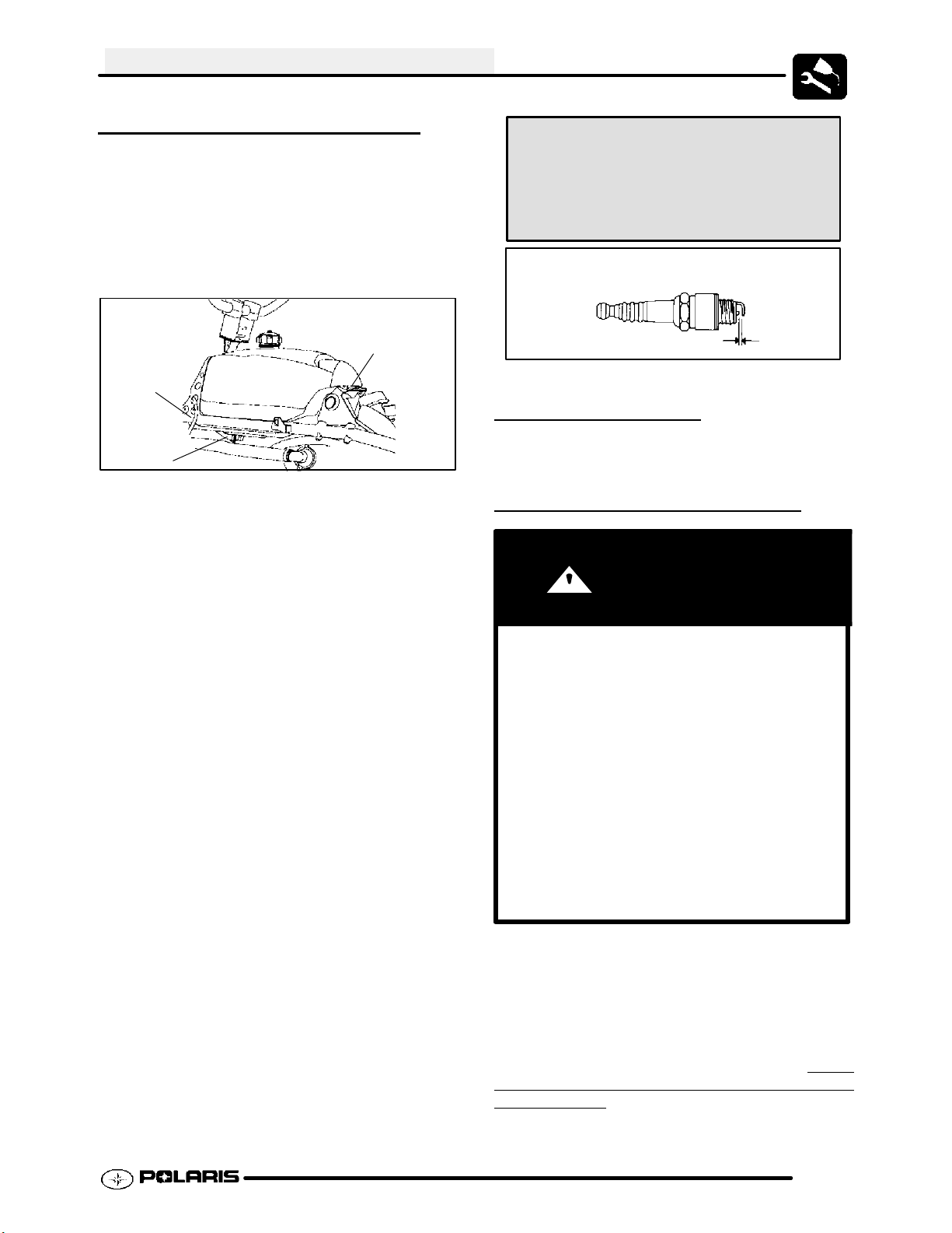
SPARK PLUG INSPECTION
Spark Plug Removal and Replacement
1. Turn the fuel valve to OFF.
2. Remove the front cab.
3. Move the fuel valve hose clamp (1) forward and
gently remove the hose from the fuel valve fitting
on the gas tank.
3
2
1
4. Remove the vent hose (2) from the instrument
panel, taking note of the hose routing for
reinstallation.
5. Remove the tank mounting bolt (3) at the rear of
the gas tank.
6. Move the tank rearward and upward over the
engine. Slowly remove the tank, being careful not
to catch any hoses, wires or other components.
Place the tank on a stable surface or work bench
to protect the valve from contamination or
damage.
7. Remove spark plug high tension lead. Clean plug
area so no dirt and debris can fall into engine
when plug is removed.
8. Remove spark plug. and inspect electrodes for
wear and carbon buildup. The insulator tip should
be a light tan color, indicating good combustion.
Look for a sharp outer electrode edge with no
rounding or erosion.
9. If needed, clean spark plug with electrical contact
cleaner or a glass bead spark plug cleaner only.
CAUTION: Wire brushes or coated abrasives
should not be used.
10. Measure gap with a wire gauge. Refer to
specifications for proper spark plug type and gap.
Adjust gap if necessary by bending the side
electrode carefully.
11. If necessary, replace spark plug with proper type.
CAUTION: Severe engine damage may occur if
the incorrect spark plug is used.
12. Apply a small amount of anti-seize compound to
the spark plug threads.
13. Install spark plug and torque to specification.
Reverse steps as needed for reassembly.
Recommended Spark Plug:
NGK DCPR8E
Spark Plug Torque:
14 Ft. Lbs. (19 Nm)
Spark Plug Gap
.035s (0.9 mm)
IGNITION TIMING
Refer to Chapter 10 for ignition timing checks.
BATTERY MAINTENANCE
WARNING
Battery electrolyte is poisonous. It contains
sulfuric acid. Serious burns can result from contact with skin, eyes or clothing. Antidote:
External: Flush with water.
Internal: Drink large quantities of water or milk.
Follow with milk of magnesia, beaten egg, or
vegetable oil. Call physician immediately.
Eyes: Flush with water for 15 minutes and get
prompt medical attention.
Batteries produce explosive gases. Keep
sparks, flame, cigarettes, etc. away. Ventilate
when charging or using in an enclosed space.
Always shield eyes when working near batteries. KEEP OUT OF REACH OF CHILDREN.
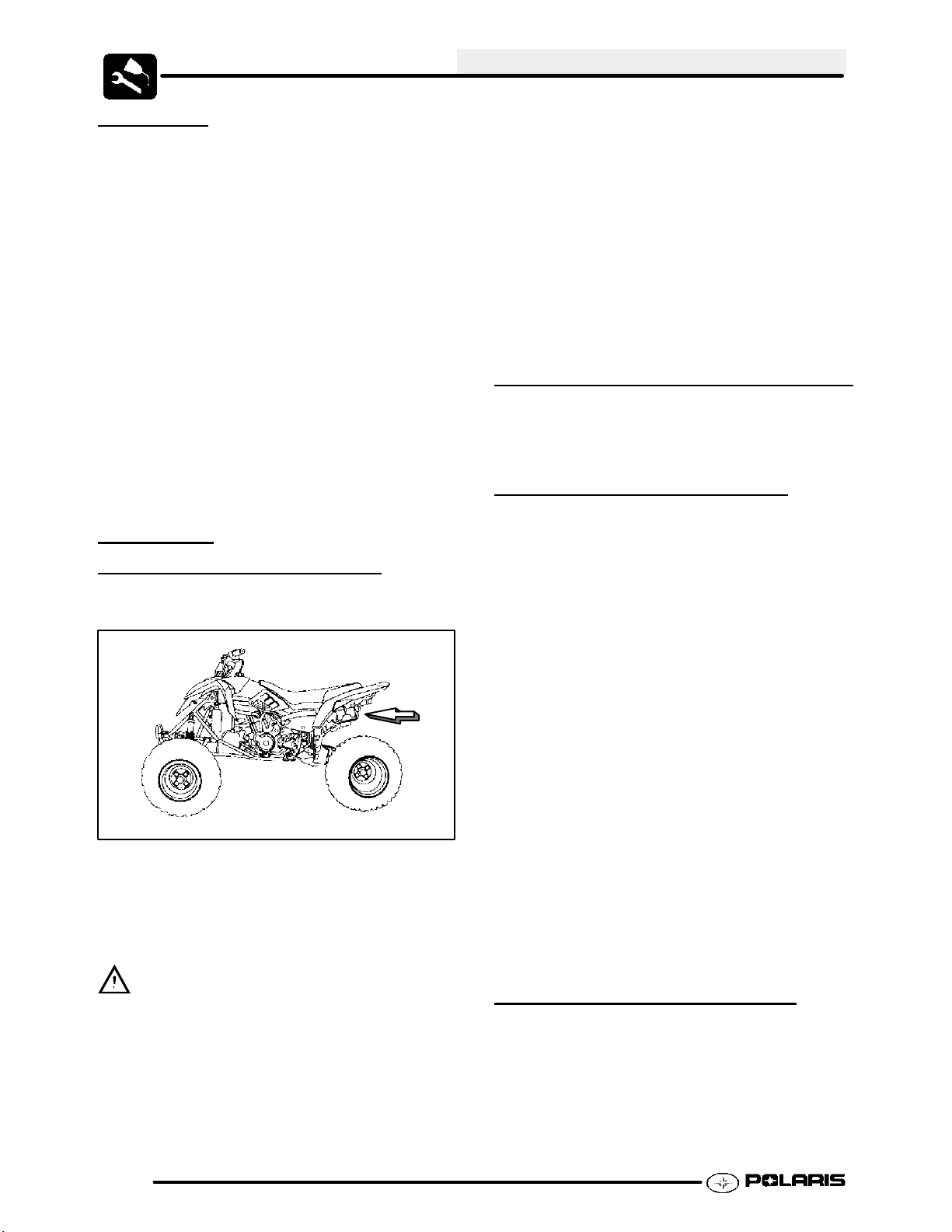
The battery is located under the left rear fender.
NOTE: All Predator ATV batteries are
Maintenance --Free design and construction.
Before placing the battery into service, check the
battery condition and charge accordingly. Use
Conventional Lead--Acid batteries is
recommended.
of
not
2.13
Page 29
MAINTENANCE
New Batteries: Batteries must be fully charged
before use or battery life will be reduced by
10-30% of full potential. Charge battery for 3--5
hours at a current equivalent of 1/10 of the
battery’s rated amp/hour capacity (i.e. 9 amp hr x
.10 = .9 amp charging). Do not use the alternator
to charge a new battery.
Maintenance--Free batteries are sealed at the
factory. The use of lead--calcium instead of
lead--antimony allows the battery acid to be fully
absorbed by the plates. Therefore, a
Maintenance--Free battery case is opaque and the
sealing caps are not removable, since there is no
need to check electrolyte level.
NEVER attempt to add electrolyte or water to a
Maintenance --Free battery. Doing so will damage
the case and shorten the life of the battery. Refer
to the Battery Maintenance Video (PN 9917987)
for proper instruction on servicing
Maintenance--Free batteries.
BATTERY
INSPECTION/REMOV
The battery is located under the left rear fender.
Battery
Location
To remove the battery:
1. Disconnect holder strap.
2. Disconnect battery negative (-) (black) cable first,
followed by the positive (+) (red) cable.
AL
Rinse well with clean water and dry thoroughly. Test
battery for condition and charge accordingly.
5. Reinstall battery, attaching positive (+) (red) cable
first and then the negative (-) (black) cable.
6. Coat terminals and bolt threads with Dielectric
Grease (PN 2871329).
7. Reinstall battery cover and holder strap.
8. Reinstall the battery caps.
9. Charge battery at 1/10 of its amp/hour rating.
Example: 1/10 of 14 amp battery = 1.4 amp
10. Reinstall the battery after testing.
BATTERY TERMINALS/BOLTS
Use Polaris corrosion resistant Dielectric Grease (PN
2871329) on battery bolts.
OFF SEASON STORAGE
To prevent battery damage during extended periods
of non-use, the following basic battery maintenance
items must be performed:
G Remove the battery from the
machine and wash the case and
battery tray with a mild solution of
baking soda and water. Rinse with
lots of fresh water after cleaning.
NOTE: Do not get any of the baking
soda into the battery or the acid will
be neutralized.
G Using a wire brush or knife, remove
any corrosion from the cables and
terminals.
G Never add water to a sealed
maintenance free battery.
G Charge at a rate no greater than 1/10
of the battery’s amp/hr capacity until
the open circuit voltage is 12.9V or
greater.
G Store the battery either in the machine
with the cables disconnected, or store
in a cool place.
CAUTION
To reduce the chance of sparks: Whenever
removing the battery, disconnect the negative
(black) cable first. When reinstalling the battery,
install the negative cable last.
3. Remove the battery.
4. Clean battery cables and terminals with a stiff wire
brush. Corrosion can be removed using a solution
of one cup water and one tablespoon baking soda.
2.14
CHARGING PROCEDURE
1. Remove the battery from the ATV to prevent
damage from leaking or spilled acid during
charging.
2. Charge the battery with a charging output no
larger than 1/10 of the battery’s amp/hr rating.
Charge as needed to raise the battery open circuit
voltage to 12.9V or greater.
Page 30
MAINTENANCE
3. Install battery in vehicle with positive terminal
toward the front. Coat threads of battery bolt with
a corrosion resistant dielectric grease.
Dielectric Grease
(PN 2871329)
4. Connect the battery cables.
ENGINE-TO-FRAME GROUND
Inspect engine-to-frame ground cable connection. Be
sure it is clean and tight. The engine to frame ground
runs under the seat and rear cab back to the battery
area.
Ground Cable
Battery Ground
LIQUID COOLING SYSTEM
G Some coolant level drop on new
machinesis normalas the system is
purgingitselfof trappedair. Observe
coolant levels often during the
break-in period.
G Overheating of engine could occur if
air is not fully purged from system.
G Polaris Premium 60/40 anti--freeze is
premixed and ready to use. Do not
dilute with water.
COOLANT STRENGTH / TYPE
Test the strength of the coolant using an antifreeze
hydrometer.
Antifreeze Hydrometer
G A 50/50 or 60/40 mixture of
antifreeze and distilled water will
provide the optimum cooling,
corrosion protection, and antifreeze
protection.
G Do not use tap water. Tap water
contains minerals and impurities
which build up in the system. Do not
add straight antifreeze or straight
water to the system. Straight water
or antifreeze may cause the system
to freeze, corrode, or overheat.
OVER
The engine coolant level is maintained by the
recoverysystem. The recovery systemcomponents
are the recovery bottle, radiator filler neck, radiator
pressure cap and connecting hose.
As coolant operating temperature increases, the
expanding(heated)excesscoolantisforcedoutofthe
radiator past the pressure cap and into the recovery
bottle. As engine coolant temperature decreasesthe
contracting(cooled)coolant isdrawnbackupfromthe
tank past the pressure cap and into the radiator.
VIEW
Polaris 60/40 Anti-Freeze / Coolant
(PN 2871323)
2.15
Page 31

MAINTENANCE
COOLING SYSTEM HOSES
Inspect all hoses for cracks, deterioration, abrasion or
leaks. Replace if necessary.
1. Check tightness of all hose clamps.
2. Do not over-tighten hose clamps at radiator or
radiator fitting may distort, causing a restriction or
leak. Radiator hose clamp torque is 36 in. lbs. (4
Nm).
2. Fill reservoir to upper mark with Polaris Premium
60/40 Anti Freeze / Coolant (PN 2871323)ora
mixture of antifreeze and distilled water as
required for freeze protection in your area.
3. Reinstall cap.
NOTE: If overheating is evident, allow system to cool
completely and check coolant level in the radiator.
Inspect for signs of trapped air in system.
Recovery
Bottle
Accessible
Under Fender
Ill.1
RADIATOR COOLANT LEVEL
INSPECTION
RADIATOR
1. Check radiator external air flow passages for
restrictions or damage.
2. Carefully straighten any bent radiator fins.
3. Remove any obstructions with compressed air or
low pressure water.
RECOVERY COOLANT
LEVEL
Never remove the radiator pressure cap when the
engine is warm or hot. Escaping steam and fluid can
cause severe burns. The engine must be allowed to
cool before removing the pressure cap.
The recovery bottle, located on the left side of the
machine, must be maintained between the minimum
and maximum levels indicated. (Ill.1)
With the engine at operating temperature, the coolant
level should be between the upper and lower marks
on the coolant reservoir. If it is not:
INSPECTION
WARNING
WARNING
Never remove the radiator pressure cap when the
engine is warm or hot. Escaping steam and fluid can
cause severe burns. The engine must be allowed to
cool before removing the pressure cap.
NOTE: This procedure is only required if the cooling
system has been drained for maintenance and/or
repair. However, if the recovery bottle has run dry, or
if overheating is evident, the level in the radiator
should be inspected via the radiator cap first and
coolant added if necessary.
NOTE: Use of a non-standard pressure cap will not
allow the recovery system to function properly.
1. Remove the radiator cap and inspect. Add
coolant as required up to the top of the filler neck.
2. Replace the cap. Start and idle the engine until it
reaches operating temperature. Stop engine and
let cool.
3. After cooling, re--verify that coolant in radiator is
at the top of the filler neck and that coolant is being
drawn through the recovery system.
1. Remove reservoir cap. Verify the inner splash
cap vent hole is clear and open.
2.16
Page 32

MAINTENANCE
COOLING SYSTEM
PRESSURE
See Chapter 3 for testing procedures.
TEST
RADIATOR SCREEN REMOVAL
1. Remove the 4 screws retaining the radiator
screen for access to the radiator fins when
cleaning.
D
B
A
E
F
Ill.1
Installation:
8. Reinstall crankcase breather filter, pre--filter and
air filter into air box. Place intake assembly into
position and reinstall clips.
9. Reinstall the intake duct to the carburetor and
tighten the clamp sufficiently.
NOTE: Apply a small amount of general purpose
grease to the sealing edges of the filter before
reinstalling.
C
G
AIR FILTER AND PRE--FILTER
SER
It is recommended that the air filter and pre--filter be
inspected frequently. When riding in extremely dusty
conditions, replacement is required more often.
The pre filter should be cleaned before each ride using
the following procedure:
1. Unlatch and remove the seat.
2. Loosen the intake duct clamp (A) on the
3. Remove clips (C) from air box cover and remove
4. Remove the air filter (E). Inspect and replace if
Cleaning:
5. Remove the pre--filter (F) and the crankcase
6. Inspect pre filter for tears or damage.
7. Inspect the intake and air box for cracks,
VICE
carburetor and pull the duct (B) off the carburetor.
cover (D). Inspect the cover. It should adhere
tightly and seal all the way around.
necessary. If the filter has been soaked with fuel
or oil it must be replaced.
breather filter (G). Clean with hot, soapy water.
Allow to dry thoroughly.
deterioration, abrasion, or leaks.
AIR BOX SEDIMENT TUBES
Periodically check the air box drain tube located
toward the rear of the machine. Drain whenever
deposits are visible in the clear tube.
1. Remove drain plug from end of sediment tube.
2. Drain tube.
3. Reinstall drain plug.
Sediment Tubes
Ill.2
NOTE: The sediment tube will require more frequent
service if the vehicle is operated in wet conditions or
at high throttle openings for extended periods.
2.17
Page 33

MAINTENANCE
CRANKCASE BREATHER
FILTER
Predator ATV engines are equipped with a crankcase
breather filter in the air box. The filter is similar in
appearance to a small foam block, and is visible on the
left side (Location G, Ill 1).
The air breather filter should be inspected or replaced
whenever the air filter is inspected.
INSPECTION
OIL AND FILTER SERVICE
NOTICE: Polaris PS--4 Engine Oil is
recommended for use in the Predator. PS--4 was
specifically designed for the Predator’s engine
and clutching system. Other oils do not contain
the needed additives to prolong engine life and
provide proper lubrication to the Predator clutch
and transmission components.
1. Place the vehicle on a level surface.
2. Clean the area around the oil tank (1) and
crankcase (2) drain plugs with clean shop
towels.
11. Remove the three cover bolts and remove the
cover.
12. Pull out the oil filter. NOTE: A spring located
behind the filter may pop out as the filter is
removed. The spring must be reinstalled with the
new filter.
Step 12.
13. Using a clean dry cloth, clean the filter sealing
surfaces.
14. Replace the o-ring in the cover.
CAUTION
Hot oil can cause serious burns to skin.
Do not allow hot oil to contact skin.
3. Run the engine for two to three minutes until
warm, then stop the engine.
4. Place a drain pan beneath the oil tank and remove
the drain plugs.
2
5. Allow the oil to drain completely.
6. Replace the sealing washer and reinstall the plug.
Torque to 14 ft. lbs. (19 Nm). NOTE: The sealing
surfaces on drain plugs, oil tank and crankcase
should be clean and free of burrs, nicks or
scratches.
7. Place a drain pan beneath the crankcase and
remove the drain plug.
8. Allow the oil to drain completely.
9. Replace the sealing washer and reinstall the plug.
Torque to 14 ft. lbs. (19 Nm).
10. Place shop towels beneath the oil filter.
1
15. Lubricate the gasket on the new filter with a film of
fresh engine oil.
16. Reinstall the spring and install the new filter with
the open end facing outward.
17. Install the cover and torque the bolts to 72-78 in.
lbs. (8-9 Nm). NOTE: The long bolt must be
placed in the forward hole.
18. Remove the dipstick and fill the oil tank with 2.25
quarts (1.9 l) of Polaris PS-- 4 Engine Oil (PN
2874414).
19. Place gear selector in neutral and set parking
brake.
20. Start the engine and let it idle for one to two
minutes. Stop the engine and inspect for leaks.
21. Re-check the oil level on the dipstick and add oil
as necessary to bring the level to the upper mark
on the dipstick.
22. Dispose of used filter and oil properly
.
2.18
Page 34

MAINTENANCE
STEERING
The steering components should be checked
periodically for loose fasteners, worn tie rod ends, ball
joints, and damage. Also check to make sure all cotter
pins are in place. If cotter pins are removed, they must
not be re-used. Always use new cotter pins.
Replace any worn or damaged steering components.
Steering should move freely through entire range of
travel without binding. Check routing of all cables,
hoses, and wiring to be sure the steering mechanism
is not restricted or limited. NOTE: Whenever steering
components are replaced, check front end alignment.
Use only genuine Polaris parts.
WARNING
Due to the critical nature of the procedures outlined in this chapter, Polaris recommends
steering component repair and adjustment be
performed by an authorized Polaris MSD--certified technician when replacing worn or damaged steering parts. Use only genuine Polaris
replacement parts.
METHOD 1:
STRAIGHTEDGE OR STRING
Be sure to keep handlebars centered. See notes.
NOTE: String should just touch side surface of rear tire on each side of machine.
Measure
from string
to rim at
front and
rear of rim.
Rear rim mea-
surement
should be
0--1/16s (0 to
.0625 cm)
more than front
rim measure-
ment.
WHEEL ALIGNMENT
One of two methods can be used to measure toe
alignment. The string method and the chalk method.
If adjustment is required, refer to following for
procedure.
NOTE: The steering post arm “frog” can be
used as an indicator of whether the handlebars
are straight. The frog should be centered with
equal clearance between the steering stops.
2.19
Page 35

MAINTENANCE
METHOD 2: CHALK
1. Place machine on a smooth level surface.
2. Set handlebars in a straight ahead position and
secure handlebars in this position. NOTE: The
steering post arm “frog” can be used as an
indicator of whether the handlebars are straight.
The frog should be centered with equal clearance
between the steering stops.
3. Place a chalk mark on the center line of the front
tires as close to the hub/axle center line as
possible, or measure to a specific distance from
the floor. NOTE: It is important that the height of
both marks be equally positioned in order to get
an accurate measurement.
4. Measure the distance between the marks and
record the measurement. Call this measurement
“A”.
5. Rotate the tires 180q by moving vehicle forward or
backward. Position chalk marks even with the
hub/axle centerline or the specified floor
measurement.
6. Again measure the distance between the marks
and record. Call this measurement “B”. Subtract
measurement “B” from measurement “A”. The
difference between measurements “A” and “B” is
the vehicle toe alignment. The recommended
vehicle toe tolerance is 0 to 1/16s ( 0 to .0625 cm)
toe out. This means the measurement at the front
of the tire (A) is 0 to 1/16s ( 0 to .0625 cm) wider
than the measurement at the rear (B).
Ill.1
STEERING INSPECTION / TIE
ROD ENDS AND HUBS
G To check for play in the tie rod end,
grasp the steering tie rod, pull in all
directions feeling for movement.
G Repeat inspection for inner tie rod
end on steering post.
G Elevate front end of machine so front
wheels are off the ground. Check for
any looseness in front hub / wheel
assembly by grasping the tire firmly
at top and bottom first, and then at
front and rear. Try to move the wheel
and hub by pushing inward and
pulling outward.
G If abnormal movement is detected,
inspect the hub and wheel assembly
to determine the cause ( possible
loose wheel nuts or loose front hub
components).
/
Chalk Line
Measurement “A”
2.20
Measurement “B”
Check for Loose Wheel or Hub
G Refer to the Body/Suspension
Chapter 5 or Final Drive Chapter for
service procedures.
Page 36

MAINTENANCE
CAMBER AND CASTER
The camber and caster are non-adjustable.
TOE ALIGNMENT
ADJUSTMENT
If toe alignment is incorrect, measure the distance
between vehicle center and each wheel. This will tell
you which tie rod needs adjusting. NOTE: Be sure
handlebars are straight ahead before determining
which tie rod(s) need adjustment.
CAUTION: During tie rod adjustment, it is very
important that the following precautions be taken when
tightening tie rod end jam nuts. If the rod end is
positioned incorrectly it will not pivot, and may break.
Hold
Rod End
EXHAUST PIPE
WARNING
G Do not perform clean out immediately
after the engine has been run, as the exhaust system becomes very hot. Serious
burns could result from contact with exhaust components.
G To reduce fire hazard, make sure that
there are no combustible materials in the
area when purging the spark arrestor.
G Wear eye protection.
G Do not stand behind or in front of the ve-
hicle while purging the carbon from the
spark arrestor.
G Never run the engine in an enclosed
area. Exhaust contains poisonous carbon monoxide gas.
G Do not go under the machine while it is
inclined. Set the hand brake and block
the wheels to prevent roll back.
Failure to heed these warnings could result in
serious personal injury or death.
Correctly
Tightened
Ill.2
To adjust toe
Jam Nut
alignment:
G Hold tie rod end to keep it from
rotating.
G Loosen jam nuts at both end of the tie
rod.
G Shorten or lengthen the tie rod until
alignment is as required to achieve
the proper toe setting as specified
in Method 1 or Method 2.
G IMPORTANT: When tightening the
tie rod end jam nuts, the rod ends
must be held parallel to prevent rod
end damage and premature wear.
Damage may not be immediately
apparent if done incorrectly. See
illustration 2.
G After alignment is complete, torque
jam nuts to 12-14 ft. lbs. (16-19 Nm).
Incorrectly
Tightened
Jam Nut
Periodically clean the spark arrestor to remove
accumulated carbon.
1. Remove the three screws (1) and remove the
arrestor (2) from the end of the muffler.
2. Use a non-synthetic brush to clean the arrestor
screen (3). A synthetic brush may melt if
components are warm.
2
1
3
3. Inspect the screen for erosion and replace if
necessary.
4. Remove and inspect the gasket. Replace if worn
or damaged.
5. Reinstall the gasket and arrestor.
6. Torque screws to 50 in. lbs. (5.6 Nm).
2.21
Page 37

MAINTENANCE
BRAKE SYSTEM INSPECTION
The following checks are recommended to keep the
brake system in good operating condition. Service life
of brake system components depends on operating
conditions. Inspect brakes in accordance with the
maintenance schedule and before each ride.
G Keep fluid level in the master cylinder
reservoir to the indicated level inside
reservoir.
G Use Polaris DOT 3 Brake Fluid (PN
2870990).
Parking Brake
Lock
Sight
Glass
BRAKE PAD INSPECTION
Pads should be changed when the friction material is
wornto3/64s (.1 cm), or about the thickness of a U.S.
dime.
3/64s
(.1cm)
Minimum
Thickness
HOSE/FITTING INSPECTION
Check brake system hoses and fittings for cracks,
deterioration, abrasion, and leaks. Tighten any loose
fittings and replace any worn or damaged parts.
Rear Master Cylinder Reservoir
Max
Min
G Check brake system for fluid leaks.
G Check brake for excessive travel or
spongy feel.
G Check friction pads for wear,
damage or looseness.
G Check surface condition of the disc.
G Inspect thickness of brake pad
friction material.
BRAKE TESTING
The foot brake should be checked for proper function.
1
2
When applied, the brake power should be sufficient
enough to stop the wheels under most conditions.
If brake operation is poor, two things must be examined:
Free Play:
Free play of the brake pedal should be 1/8 - 1/4
inch (3.2 - 6.35 mm).
If free play is excessive, inspect pedal, linkage, and
master cylinder for wear or damage and replace any
parts as needed.
2.22
Page 38

MAINTENANCE
Bleeding:
If free play is correct and brake pedal travel is still
excessive, air may be trapped somewhere in the
system. Bleed the hydraulic auxiliary brake system in
a conventional manner, following the procedure
outlined in Brake Chapter 6.
SUSPENSION: SPRING
PRELOAD
Operator weight and vehicle loading affect
suspensionspringpreloadrequirements.Adjustas
necessary.
Front Suspension
G Compress and release front suspension.
Damping should be smooth throughout
the range of travel.
G Check all front suspension components
for wear or damage.
G Inspect front strut cartridges for leakage.
1. Raise and safely support the front of the ATV off
the ground to allow the suspension to fully extend.
2. Turn the adjusting ring to the left (A) to increase
preload. Turn the ring to the right (B) to decrease
preload. NOTE: The fully extended installed
spring length (C) should not exceed 11.875
inches (30 cm). Exceeding this length may cause
the spring to unseat from the shock body.
ADJUSTMENT
REAR
Setting Spring
Length
Softest 11.875 inches Clicker
Factory 11.625 inches Clicker
Firmest 11. 0 inches Clicker
Compression
Damping
Position 1
Position 4
Position 8
1
A
B
2
Rear Spring
Adjustment
DRIVE CHAIN AND
SPROCKET
INSPECTION
Rebound
Damping
15 clicks
from
closed
10 clicks
from
closed
3 clicks
from
closed
C
FRONT
Setting Spring Length
Softest 11.875 inches
Factory 11.5 inches
Firmest 11.125 inches
A
B
C
Polaris ATV drive chains are equipped with O-ring
sealed permanently greased pins and rollers. The
sprockets and outer rollers require periodic
lubrication. Lubricate the chain with Polaris Chain
Lubricant (PN 2872073).
Inspect the drive chain for missing or damaged
O-Rings, link plates, or rollers. Do not wash the chain
with a high pressure washer, gasoline or solvents; do
not use a wire brush to clean the chain as damage to
the O-Rings may occur. Clean chain with hot soapy
water and a soft bristled nylon brush.
Never allow battery acid to contact the drive chain.
2.23
Page 39

SPROCKET INSPECTION
MAINTENANCE
Inspect the sprocket for worn, broken or bent teeth.
Inspect chain for excessive
wear, missing o--rings, etc.
Chain Tension
Limit:
1/4s (6mm)
To check for wear, pull upward on the chain. Replace
sprocket if chain movement exceeds 1/4s (.6 cm).
DRIVE CHAIN INSPECTION
The chain must be replaced when it reaches 3%
elongation.
1. Stretch the chain tightly in a straight line.
2. Measure the length of twenty pitches (pins) from
pin center to pin center, and compare to the
specification. Replace the chain if the length
exceeds the wear limit.
Drive Chain Wear Limit, 20 Pitch Length:
Std: 12.5s (32 cm)
Wear Limit: 12.875s (32.7 cm)
3. When replacing or reinstalling drive chain, install
the closed end of the splice link clip as shown, with
the closed end leading in forward operation.
There should be a .003--.005” (.076--.127 mm)
gap between the side plate of the chain and the
splice link clip. See Illustrations 1 and 2.
If there is space
Master Link
Do not
press plate
in too far.
Ill. 2
between outside
edge of the master link and plate,
back the plate
out slightly.
DRIVE CHAIN ADJUSTMENT,
CONCENTRIC
CAUTION: Never adjust or operate the vehicle
with the rear drive chain too loose or too tight as
severe damage to the transmission and drive
components can result. Chain tension must be
inspected with the swing arm in the position shown in
the illustration so that the axle, swingarm pivot, and
drive spocket are aligned horizontally (B).
Break-In: It is extremely important to maintain proper
chain tension to ensure the best possible chain life.
There is a chain break-in period of approximately 100
miles or two (2) tanks of fuel. During this time chain
tension should be watched very closely and loads to
the chain should be kept light.
Checking Chain Tension:
Check the amount of chain slack by moving the
vehicle slightly forward to gain slack at the top side of
the rear chain.
SWINGARM
Ill. 1
2.24
Proper
Splicelink Clip
Opening
Position
.003--.005”
(.076--.127 mm)
Gap after installation
Rear Chain
Shown
1. Collapse the suspension with an adjustable
(buckle type) trailer tie down strap (A). Fasten the
strap around the axle and rear bumper tube.
2. Tighten the strap until a straight line (B) can be
drawn from the axle to the transmission output
shaft, intersecting the swing arm pivot. This
establishes the tightest chain position.
3. At this point (C) the chain should have 1/4” - 3/8“
(0.6 -0.9 cm) deflection. Use the procedure on
the following page if the chain needs adjustment.
Page 40

MAINTENANCE
3. Roll the vehicle ahead or back to adjust chain
slack to the proper dimension.
C
A
B
C
4. Tighten the eccentric locking bolts to 45 ft. lbs.
(61 Nm).
C
A
B
ADJUSTMENT PROCEDURE SWINGARM / REAR
Loosen Eccentric
clamp bolts (Step 2)
AXLE
CAUTION: DO NOT OVER-TIGHTEN ECCENTRIC
CLAMP BOLTS. PRE-MATURE BEARING
FAILURE MAY RESULT.
SHOCK REBOUND AND
COMPRESSION
DAMPING
ADJUSTMENT
Rebound Damping
1. Locate the rebound damping clicker drum
between the lower spring seat and the lower
shock mount.
2. Turn the clicker to the left (A) to increase the
rebound damping. Turn it to the right (B) to
decrease rebound damping.
NOTE: The clicker drum is effective up to 15
clicks from fully closed. The rebound damping is
factory set at 10 clicks from fully closed.
1. Loosen two eccentric locking bolts.
2. Insert a pin punch into the eccentric axle housing.
Step 2
Step 1
A
Compression Damping
The compression damping clicker drum is located on
top of the shock reservoir, under the left rear fender.
B
2.25
Page 41

MAINTENANCE
It has eight possible positions ranging from position 1
(softest) to 8 (firmest). The compression damping is
factory set at position 4. To adjust, turn the clicker
drum to the desired setting.
Adjust
CONTROLS
Check controls for proper operation, positioning
and adjustment.
Handlebars
If desired, the handlebars can be adjusted for rider
preference.
WARNING
Improper adjustment of the handlebars or incorrect
torquing of the adjuster block bolts can cause
limited steering or loosening of the handlebars,
which could result in loss of control and serious
injury or death.
contact the gas tank or any other part of the
machine when turned fully to the left or right.
3. Torque the front two bolts to 10-12 ft. lbs. (14-17
Nm), then torque the rear two bolts. A gap of up to
1/8” will remain at the rear bolts.
WHEELS
Inspect all wheels for runout or damage. Check wheel
nuts and ensure they are tight. Do not over tighten the
wheel nuts.
WHEEL, HUB, AND SPINDLE
TORQUE T
Item Specification
Front Wheel Nuts 20 Ft. Lbs. (41 Nm)
Rear Wheel Nuts 20 Ft. Lbs. (41Nm)
Front Spindle Nut 40 Ft. lbs. (55 Nm)
Rear Hub Retaining Nut 80 Ft. Lbs. (108 Nm)
ABLE
WHEEL REMOVAL:
FRONT OR REAR
Wheel Removal
1. Stop the engine, place the transmission in gear
and lock the parking brake.
2. Loosen the wheel nuts slightly.
3. Elevate the side of the vehicle by placing a
suitable stand under the footrest frame.
4. Remove the wheel nuts and remove the wheel.
Wheel Installation
1. Remove the instrument panel and locate the
handlebar bolts (1).
1
10--12 ft.lbs.
(14--17 Nm)
2. Loosen the four bolts and adjust the handlebar to
the desired height. Be sure the handlebars do not
2.26
1. With the transmission in gear and the parking
brake locked, place the wheel in the correct
position on the wheel hub. Be sure the valve stem
is toward the outside and rotation arrows on the
tire point toward forward rotation.
2. Attach the wheel nuts and finger tighten them.
3. Lower the vehicle to the ground.
4. Securely tighten the wheel nuts to the proper
torque listed in the table.
CAUTION:
Page 42

MAINTENANCE
Improperly installed wheels could affect vehicle
handling and tire wear. On vehicles with tapered rear
wheel nuts, make sure tapered end of nut goes into
taper on wheel.
Flange Nuts:
Flat side against wheel
WARNING
Operating your ATV with worn tires, improperly
inflated tires, non-standard tires or improperly
installed tires will affect vehicle handling and could
cause an accident resulting in serious injury or
death.
Maintain proper tire pressure as described on the
ATV decal and in the owner’s manual.
Always use original equipment size and type when
replacing tires.
Make sure the wheels are installed properly.
Always replace tires when the tread depth
measures 1/8s (.3 cm) or less.
TIRE PRESSURE
CAUTION:
Maintain proper tire pressure. Refer to the warning
tire pressure decal applied to the vehicle.
Tire Pressure Inspection (PSI - Cold)
Front Rear
5 5
TIRE INSPECTION
G Improper tire inflation may affect ATV
maneuverability.
G When replacing a tire always use
original equipment size and type.
G The use of non-standard size or type
tires may affect ATV handling.
Tire Tread Depth
Always replace tires when tread depth is worn to
1/8s (3 mm) or less.
1/8I (.3 cm)
FRAME, NUTS, BOLTS,
ASTENERS
F
Periodically inspect the torque of all fasteners in
accordance with the maintenance schedule. Check
that all cotter pins are in place. Refer to specific
fastener torques listed in each chapter.
2.27
Page 43

NOTES
MAINTENANCE
2.28
Page 44

ENGINE
CHAPTER 3 ENGINE
Torque Specifications 3.2-3.3........................
ES50PL Service Data 3.3-3.4........................
Special Tools 3.5...............................
Torque Patterns 3.5.............................
Piston Identification / Compression Test 3.5........
Cooling System Pressure Test 3.6................
Cooling System Specifications 3.6................
Engine Removal 3.7............................
Engine Installation Notes 3.8.....................
ES50PL Engine Lubrication 3.9..................
ES50PL Crankshaft Inspection 3.9................
ES50PL Oil Pump Priming Procedure 3.10..........
ES50PL Lubrication/Oil Flow 3.10.................
ES50PLEngine Oil Flow Diagram 3.11.............
ES50PL Engine Exploded Views 3.12..............
ES50PL Engine Top End Service 3.13-3.23..............
Camshaft 3.14-3.15.............................
Cylinder Head 3.15-3.20.........................
ES50PL Engine Bottom End Service 3.24-3.36...........
Transmission 3.30-3.31...........................
Crankshaft Runout Inspection 3.32............
Crankcase & Bearings 3.33...................
Water Pump Shaft / Seal Service 3.33-3.35..........
ES50PL Engine Assembly 3.35-3.39....................
Crankcase 3.35.............................
Piston / Cylinder 3.36-3.37........................
Cam Timing 3.38-3.39............................
Cam Timing Diagram 3.40........................
Cylinder Honing 3.41.............................
Valve Seat Service 3.41-3.43..........................
Troubleshooting 3.44.............................
Spark Plug Fouling Checklist 3.45.................
Cooling Troubleshooting Checklist 3.45.............
3
3.1
Page 45

ENGINE
TORQUE SPECIFICATIONS
TORQUE SPECIFICATIONS
Fastener Thread ES50PL
Ft. Lbs. (Nm)
Blind Plug (Crankcase) 1/8 PT 6.6-11.1 (9-15 Nm)
Blind Plug (Oil Filter Cover) 1/4 PT 12.5-17 (17-23 Nm)
BearingStopPlates 6mm 8.1-9.6 (11-13 Nm)
Camshaft Chain Tensioner Blade Bolt 8mm 10-12.2 (13.5-16.5 Nm)
Camshaft Chain Tensioner 6mm 6.6-8.1 (9-11 Nm)
Camshaft Chain Tensioner Cap 10mm 14-19 (20-25 Nm)
Camshaft Support 8mm 6.6-8.1 (9-11 Nm)
Carburetor Adaptor 8mm 11.8-14.8 (16-20 Nm)
Crankcase Cover 8mm 6.6-8.1 (9-11 Nm)
Crankshaft Nut (Primary Drive Sprocket) 18mm 59-74 (80-100 Nm)
Crankshaft Nut (Ball Bearing at Crankshaft) 32mm 66-81 (90-110 Nm)
Cylinder Base/Head Bolts 14mm
6mm
Clutch Basket Nut 18mm 66-81 (90-110 Nm)
Clutch Cover 6mm 6.6-8.1 (9-11 Nm)
Drive Sprocket and Sprocket Cover 6mm 6.6-8.1 (9-11 Nm)
Flywheel -- Apply engine oil to threads 14mm 111-125 (150-170 Nm)
Neutral Indicator Switch 5mm 2.2-3.7 (3-5 Nm)
Oil Delivery Pipe 12mm 11.1-15.5 (15-21 Nm)
Oil Drain Bolt (Crankcase) 14mm 14-17 (19-23 Nm)
Oil Filter Cover Housing and Oil Pump Case 6mm 6.6-8.1 (9-11 Nm)
Oil Hose Fittings 8mm 6.5-11 (9-15 Nm)
OneWayValvePlug 11mm 14.8-19.2 (20-26 Nm)
One Way Clutch Screws 6mm 9.6-11.1 (13-15 Nm)
Pulser Coil -- Apply PN2871557 to threads 5mm 1.8-2.6 (2.5-3.5 Nm)
Pressure Plate Screws 6mm 6.6-8.1 (9-11 Nm)
Shift Cam 6mm 5.9-7.4 (8-10 Nm)
Shift Lever 6mm 6.6-8.1 (9-11 Nm)
Stopper (Detent) Arm ---- Apply PN2871557 to threads 6mm 6.6-8.1 (9-11 Nm)
Stator Housing Cover 6mm 6.6-8.1 (9-11 Nm)
Stator Plate 5mm 4.1-5.8 (5.5-6.5 Nm)
Starter Motor 6mm 6.6-8.1 (9-11 Nm)
Spark Plug 12mm 11.1-14.8 (15-20 Nm)
Timing Cover Plug (Center) 32mm 7.4-8.8 (10-12 Nm)
Timing Cover Plug (Timing window) 14mm 2-4 (3-5 Nm)
Thermo Cover 6mm 5.2-6.6 (7-9 Nm)
Thermo Switch 3/8 NPT 23.6-28 (32-38 Nm)
Refer to Page 3.37
6-8 (9-11 Nm)
3.2
Page 46

ENGINE
g
j
j
y
g
easueae
g
g
TORQUE SPECIFICATIONS
TORQUE SPECIFICATIONS
Fastener Thread ES50PL
Ft. Lbs. (Nm)
Valve Cover 6mm 6.6-8.1 (9-11 Nm)
Water Pump Impeller 6mm 6.6-8.1 (9-11 Nm)
Water Pump Housing Cover 6mm 6.6-8.1 (9-11 Nm)
ES50PL ENGINE SERVICE DATA
Cylinder Head / Valve ES50PL
Camshaft Cam lobe height In
Camshaft journal OD
Camshaft journal bore ID
Camshaft Oil clearance
Cylinder Head
Valve Seat Contacting width In
Valve Guide
Valve Margin thickness In
Valve Stem diameter
Surface warpage limit .0020s (.05 mm)
Standard height 4.975s (126.4 mm)
**Measure valve
stem height
Inner diameter .2362-.2367s (6.0-6.012 mm)
Protrusion above head .535-.551s (13.6-14.0 mm)
Stem oil clearance Std
Overall length
Std 1.667-1.671s (42.35-42.45 mm)
Limit 1.655s (42.05 mm)
Ex
Std 1.667-1.671s (42.35-42.45 mm)
Limit 1.655s (42.05 mm)
Mag .9821-.9828s (24.946-24.963 mm)
PTO .8652-.8655s (21.976-21.985 mm)
Mag .9842-.9851s (25.000-25.021 mm)
PTO .8657-.8661s (21.990-22.000 mm)
Mag .0014-.0029s (.037-.075 mm)
PTO .0001-.0009s (.005-.024 mm)
Limit .004s (.10 mm)
Std 1.5255s (38.75 mm)
Limit 1.5425s (39.18 mm)
Ex
Std 1.5255s (38.75 mm)
Limit 1.5377s (39.06 mm)
Std .039s (1.0 mm)
Limit .031s (.8 mm)
Ex
Std .039s (1.0 mm)
Limit .031s (.8 mm)
In .2343-.2348s (5.950-5.965 mm)
Ex .2341-.2346s (5.945-5.960 mm)
In .0014-.0024s (.035-.062 mm)
Ex .0016-.0026s (.040-.067 mm)
Limit .0059s (.15 mm)
In 4.031s (102.4 mm)
Ex 4.059s (103.1 mm)
3.3
Page 47

ENGINE
q
ggg
p
ggp
p
g
g
g
g
g
g
g
ES50PL ENGINE SERVICE DATA
Valve Spring Overall length
Limit = --.079s (--2.0 mm)
Squareness
Cylinder / Piston / Connecting Rod EH50PL12
Cylinder
Piston
Piston Pin
Piston Ring to ring groove clearance To p
Piston Ring installed gap To p
Connecting
Rod
Crankshaft Crankshaft runout limit .0024s (.06 mm)
Surface warpage limit (mating with
cylinder head)
Cylinder bore Std 3.9055-3.9062s (99.20-99.22 mm)
Taper limit .002s (.05 mm)
Out of round limit .002s (.05 mm)
Piston clearance
Outer diameter Std 3.9037-3.904s (99.155-99.170 mm)
Piston Pin Bore Standard I.D. .9055-.9057s (23.001-23.007 mm)
Outer diameter .9053-.9055s (22.996-23.0 mm)
Piston pin to pin bore clearance .0002-.0004s (.001-.0011 mm)
Degree of fit Piston pin must be a push (by hand) fit at
Connecting rod small end ID .9058-.9063s (23.007-23.020 mm)
Connecting rod small end
radial clearance
Connecting rod big end side
clearance
Connecting rod big end
radial clearance
Inner 1.575s (40.0 mm)
Outer 1.650s (41.9 mm)
Inner .067-s (1.7 mm)
Outer .071s (1.8 mm)
.002s (.05 mm)
Std .0018-.0025s (.046-.065 mm)
Limit .0039s (.10 mm)
68q F(20q C)
Std .0012-.0028s (.030-.070 mm)
ring
Second
ring
ring
Second
ring
Oil ring
Limit .0059s (.15 mm)
Std .0012-.0028s (.030-.070 mm)
Limit .0059s (.15 mm)
Std .008-.012s (.20-.30 mm)
Limit .027s (.7 mm)
Std .014-.019s (.35-.50 mm)
Limit .031s (.8 mm)
Std .004-.019s (.10-.50 mm)
Limit .039s (1.0 mm)
Std .0003-.0009s (.007-.024 mm)
Limit .0020s (.05 mm)
Std .0035-.0196s (.09-.50 mm)
Limit .0255s (.65 mm)
Std .0004-.0015s (.011-.038 mm)
Limit Same as standard
KEY - Std: Standard; OS: Oversize; ID: Inner Diameter; OD: Outer Diameter; Mag: Magneto Side; PTO: Power
Take Off Side
3.4
Page 48

ENGINE
SPECIAL TOOLS
PART NUMBER TOOL DESCRIPTION
2872105 Water Pump
2200634 Valve Seat
2870390 Piston Support Block
PA-- 45958 Cam Chain Tensionor
PA-- 46075 Flywheel Puller
PA-- 46076 MAG End Crankshaft
PA-- 46087 Crankcase Separator
PA-- 46077 MAG End Crankshaft
2871283 Crankshaft/Water
5131135 Water Pump Install Kit
PA-- 46502 Valve Spring
Mechanical Seal Puller
Reconditioning Kit
Assembly Tool
Nut Remover/Installer
Installer
Pump Seal Install Kit
Compressor
ENGINE FASTENER TORQUE
TTERNS
PA
Tighten cylinder head, cylinder base, and crankcase
fasteners in 3 steps following the sequence outlined
below.
PISTON IDENTIFICATION
The piston may or may not have an identification
mark for piston placement. If the piston has an
identification mark, follow the directions for piston
placement below. If the piston does not have an
identification mark, the direction for placement of the
piston does not matter.
Note the directional and identification marks when
viewing the pistons from the top. Identifying marks
such as “F”, “ ! ”, “ "”orD must always be
positioned to the flywheel side of the engine. Other
marks are used for identification as to diameter, length
and design. Four stroke engine rings are a
rectangular profile. See text for oil control ring rail
installation. Use the information below to identify
pistons and rings:
COMPRESSION TEST
NOTE: This engine has built--in decompression
components. Compression readings will vary in
proportion to cranking speed during the test. Average
compression (measured) is about 85--90 psi @ 400
RPM during a compression test.
A cylinder leakdown test is the best indication of
engine condition. Follow manufacturer’s instructions
to perform a cylinder leakage test. (Never use high
pressure leakage testers, as crankshaft seals may
dislodge and leak).
Cylinder Head/Cylinder Base
8mm
23
1
2
4
6
4
8
11
5
6
5
10
1
7
9
Cylinder Compression
w/ decompression
Standard: 85--90 PSI @ 400 RPM
Cylinder Leakdown
Service Limit 10 %
(Inspect for cause if leakage exceeds 10%)
3
12
3.5
Page 49

ENGINE
COOLING SYSTEM
WARNING: Never remove radiator cap when engine
is warm or hot. The cooling system is under pressure
and serious burns may result. Allow the engine and
cooling system to cool before servicing.
FLOW
Radiator
Thermostat
Cylinder
Head
Water
Pump
Cylinder
Coolant Flow
From Thermostat
To Wat e r pum p
Diagram
Sensor
COOLING SYSTEM
SPECIFICA
TIONS
Pressure test
here with cap
in place
RADIATOR CAP / SYSTEM
PRESSURE
1. Remove recovery bottle hose from coolant filler
neck.
2. Connect a Mity Vact (PN 2870975) to radiator
and pressurize system to 10 PSI. The system
must retain 10 lbs of pressure for five minutes or
longer. If pressure loss is evident within five
minutes, check radiator, all cooling system hoses
and clamps, or water pump seal.
Radiator Cap Pressure Test
1. Remove radiator cap and test using a cap tester
(commercially available).
2. The radiator cap relief pressure is 13 psi. for all
models. Replace if cap releases at less than 13
psi.
TEST
Description Temperature
Fan Switch (Off)
Fan Switch (On)
Hot Light On 221q F (105q C)
System Capacity 2.25 Quarts (2.1 L)
Radiator Cap Relief
Pressure
RECOMMENDED COOLANT
Use only high quality antifreeze/coolant mixed with
distilled water in a 50/50 or 60/40 ratio, depending on
freeze protection required in your area. CAUTION:
Using tap water in the cooling system will lead to a
buildup of deposits which may restrict coolant flow
and reduce heat dissipation, resulting in possible
engine damage. Polaris Premium 60/40
Antifreeze/Coolant (PN 2871323) is recommended
for use in all cooling systems and comes pre-mixed,
ready to use.
150q F(65q C) r 8q
180q F(82q C) r 7q
13 PSI
3.6
Page 50

ENGINE
ACCESSIBLE COMPONENTS
The following components can be serviced or
removed with the engine installed in the frame:
G Flywheel
G Alternator/Stator
G Starter Motor/Starter Drive
G Water Pump / Water Pump
Mechanical Seal*
*Mechanical Water Pump Seal Removal Tool (PN
2872105) is required to replace mechanical seal with
engine in frame.
The following components require engine
removal for service:
G Counterbalance Shaft or Bearing(s)
G Connecting Rod
G Crankshaft
G Crankshaft Main Bearings
G Cylinder Head
G Cylinder
G Piston/RIngs
G Camshaft
G Cams
G Cam Chain and Sprockets
G Transmission Gears and Bearings
ENGINE REMOVAL
1. Thoroughly clean the ATV engine and chassis.
2. Clean work area.
3. Support the ATV with jackstands under the
footrests at a height sufficient to raise the rear
wheels off the floor at least 5 inches (12.7 cm)
4. Drain coolant and engine oil.
5. Disconnect battery cables, starting with the
negative (-) cable first.
6. Remove the following components:
G Seat
G Front Cab (Refer to Chapter 5)
G Fuel Tank (Refer to Chapter 4)
G RH footwell (Refer to Chapter 5)
7. Remove air intake duct.
8. Remove carburetor (Caution: fuel will leak if carb
is turned upside down). In most instances, the
carburetor will not have to be disconnected from
the throttle cable, choke cable and fuel line for
engine removal. Insert a shop towel into the
carburetor flange to prevent dirt from entering the
intake of the engine.
9. Disconnect all electrical connections to the
engine. (coolant sensor, neutral switch, plug wire,
starter cable, ground cable, ) Remove the
magneto side cover, leaving the electrical
components attached, and secure out of the way.
10. Remove clutch linkage and secure out of the way.
11. Remove fasteners from exhaust pipe and remove
header pipe.
12. Remove oil tank and hoses as an assembly.
Disconnect vent line and secure out of the way.
13. Loosen chain, disconnect and remove . NOTE:
An acceptable alternative is to remove the
transmission drive sprocket and roll chain off.
14. Remove all engine mount nuts and engine mount
plates, starting at the rear with the combination
engine/swing arm pivot mount first. Using a
suitable tool, push the bolt out far enough to
loosen the engine, but not drop the swing arm
pivot. Use a jack under the bearing carrier to
relieve tension from the pivot bolt for easier
removal and installation.
15. With an assistant helping you, remove the engine
by tilting forward and turning to exit through left
side of frame.
To reinstall the engine, reverse the procedures. Refer
to engine installation notes on Page 3.8.
3.7
Page 51

ENGINE
ENGINE INSTALLATION NOTES
After the engine is installed in the frame, review this
checklist and perform all steps that apply:
General Items
G Install previously removed
components using new gaskets,
seals, and fasteners where applicable.
G Perform checks on fluid levels,
controls, and all important areas on
the vehicle as outlined in the daily
pre-ride inspection checklist (refer to
Chapter 2 or the Owner’s Manual).
G Verify clutch and lever freeplay
according to procedures on Page 2.9.
G Adjust chain tension according to
procedures on Page 2.25.
Exhaust
G Replace exhaust gaskets. Seal
connections with high temp silicone
sealant if applicable.
G Verify all fasteners are in good
condition and torqued properly.
Bleed Cooling System
NOTE: Refer to Page 3.6 for hose routing. Bleeding
generally is necessary after repairs to purge any air
that may remain in the system during filling.
1. Remove radiator cap and slowly add coolant to
the bottom of filler neck.
2. Fill coolant reservoir tank to full mark.
3. Install radiator cap half--way and gently squeeze
coolant hoses to force any trapped air out of
system.
4. Again, remove radiator cap and slowly add
coolant to the bottom of fill neck if required.
5. Start engine and observe coolant level in the
radiator. Allow air to purge and top off as necessary.
Reinstall radiator cap and bring engine to operating
temperature. After engine is cool, check level in
reservoir tank and add coolant if necessary.
NOTE: Should the reservoir tank become empty, it
will be necessary to refill at the radiator and repeat the
bleeding procedure.
Engine Break In Period
The break in period for a Polaris ATV engine is defined
as the first ten hours of operation, or the time it takes
to use two full tanks of gasoline. No single action on
your part is as important as a proper break in period.
Careful treatment of a new engine will result in more
efficient performance and longer life for the engine.
Perform the following procedures carefully.
New and rebuilt engines require a break--in oil change
at 1 hour of engine run time.
OIL RECOMMENDATION
Polaris PS--4 All Season synthetic oil is specially
formulated for use with wet--clutch transmissions.
Never substitute or mix oil brands. Serious engine
damage and voiding of warranty can result.
For new or rebuilt engines, do not operate at full
throttle or high speeds for extended periods during
the first three hours of use. Excessive heat can
build up and cause damage to close fitted engine
parts.
1. Fill fuel tank with unleaded or leaded fuel which has
a minimum pump octane number of 87= (R+ M)/2.
2. Check oil reservoir level indicated on dipstick.
Add oil if necessary.
SAFE
3. Drive slowly at first to gradually bring engine up to
operating temperature.
4. Vary throttle positions. Do not operate at
sustained idle or sustained high speed.
5. Perform regular checks on fluid levels, controls
and all important areas on the vehicle.
6. Pull only light loads during initial break in.
7. Change break in oil and filter at 1 hour or 100
miles.
ADD 8 OZ
3.8
Page 52

ENGINE
CRANKSHAFT
STRAIGHTENING
Lubricate the bearings and clamp the crankshaft
securely in the crankshaft alignment fixture. Refer to
the illustrations below.
Crankshaft Alignment Fixture
(PN 2870569)
NOTE:The rod pin position in relation to the dial
indicator position tells you what action is required to
straighten the shaft.
1. To correct a situation like the one shown in the
illustration, strike the shaft at point A with a brass
hammer.
HIGH .002 (.05mm)
HIGH .005 (.13mm)
A
NOTE: Maximum allowable runout is .0024I
A
ES50PL ENGINE
LUBRICA
Oil Type:
Polaris PS--4 Synthetic (PN 2874414)
TION
HIGH .004 (.1mm)
A
B
SUPPORT CRANKSHAFT
HERE.
2. To correct a situation like the one shown in the
illustration, squeeze the crankshaft at points A.
(Use tool from alignment kit).
HIGH .002 (.05mm)
HIGH .004 (.1mm)
HIGH .005 (.13mm)
AA
Capacity:
Approximately 2.25 U.S. Quarts (2.1L)
Filter:
PN 3084963
Drain Plug / Screen Fitting:
14.8--17 ft. lbs. (20--23 Nm)
(If fitting is removed, follow
oil pump priming procedure).
Oil Pressure Specification:
20 PSI @ 5500 RPM, Polaris PS--4 Synthetic
(Engine Hot)
OIL PRESSURE TEST
1. Remove blind plug on front right oil filter cover.
2. Insert a 1/8 NPT oil pressure gauge adaptor and
attach the gauge.
3. Start engine and allow it to reach operating
temperature, monitoring gauge indicator.
NOTE: Use only Polaris PS 4 Synthetic Engine
Lubricant (PN 2874414).
Oil Pressure at 5500 RPM (Engine Hot):
Standard: 20 PSI
Minimum: 12 PSI
3. If the crank rod pin location is 180_ from the dial
indicator (opposite that shown above), it will be
necessary to spread the crankshaft at position A
as shown in the illustration at right. When
rebuilding and straightening a crankshaft, runout
must be as close to zero as possible.
3.9
Page 53

ENGINE
OIL PUMP PRIMING
PROCEDURE
NOTE:Oil pump priming procedures must be
performed whenever the oil hose connection
between the oil tank and pump inlet has been
disconnected.
1. Clamp or pinch off vent line approximately 2I
from oil tank, between the end of oil tank vent
fitting and the vent line.
Approx.
To Ai r B ox
2I
Oil Tank
Pinch Off
Vent Hose
2. Run engine for 15--20 seconds at 3000--4000 rpm.
3. Shut off engine. Remove the vent line clamp. The
oil pump should now be properly primed and ready
for field operation. Note: If the system is primed
properly you should hear some air release, if you do
not, the system has not primed. repeat the process
if necessary.
OIL FLOW -- ES50PL
The chart on Page 3.11 describes the flow of oil
through the ES50PL engine. Beginning at the oil tank,
the oil flows through a screen fitting in the bottom of
the tank and into the oil supply hose. The feed side
of the oil pump draws oil through the hose and into the
crankcase oil gallery, pulling the oil through another
passage to the one way valve. (When the engine is
off, the one way valve closes to prevent oil in the tank
from draining into the crankcase.) Oil is then pumped
to the oil filter. If the oil filter is obstructed, a bypass
valve contained in the filter allows oil to bypass the
filter element.
At this point, the oil is diverted in three directions. Oil
is supplied to the crankshaft through a pto side oil
passage, lubricating the crank bearings, crankpin,
piston, cylinder and connecting rod bearings. A
delivery pipe supplies oil to the top of the cylinder head
and the transmission main shaft. Oil is delivered
though the pipe and enters the camshaft through the
cam support oil gallery. The camshaft journals are
lubricated through holes in the camshaft. Oil
lubricates the cam chain sprockets and cam lobes via
an oil jet, which drains to the crankcase.
Another oil path flows from the delivery pipe to the
transmission main shaft. Here it passes through the
oil gallery to lubricate the transmission gears, clutch
and bearings.
Residual oil from the lubrication of the crankshaft and
connecting rod indirectly lubricates the cylinder wall,
piston, rings, connecting rod small end bearing, piston
pin, oil/water pump drive gears, cam chain, drive
sprocket, and Magneto end crankshaft main bearing.
A one-way valve is located on the right front (PTO)
side of the crankcase. This valve prevents oil in the
tank from draining into the engine crankcase when the
engine is off. The valve mechanism consists of a
plunger, return spring, guide plug, and sealing
washer. When the engine is running, oil pressure lifts
the plunger off the seat, allowing oil flow. When the
engine is off, spring pressure forces the plunger
against the oil passage seat, preventing oil flow from
the tank to the sump. The one-way valve requires very
little maintenance. If engine oil drains into the
crankcase when the engine is off, inspect the valve
sealing surface for debris or damage. Inspect the
return spring for distortion or damage.
3.10
Page 54

ENGINE
ES50PL OIL FLOW
ES50PL OIL FLOW CHART
To p o f Oil Tank
Crankcase (Mag Side)
Crankcase (Clutch Side)
Prevents oil from
draining into
crankcase with
engine off
Oil Tank
Oil Hose
Oil Gallery
Oil Gallery
Oil Pump
(Feed)
One Way Valve
Indirect
Lubrication
Oil FilterBypass
Oil Hose
Crankcase (Mag Side)
Oil Gallery
Cylinder
Piston
ConnectingRod
(Small End)
Large End
Bearing
Crank Pin
Crankcase
Ball Bearing
(Mag Side)
(Clutch Side)
Oil Gallery
Crankcase
Oil Jet
Cam Support
(Scavenging)
Cam Chain
Cam & Crank Sprocket
Chain Room
Cam Lobe
Valve Lifter
Oil Gallery
Oil Pump
Oil Strainer
Cam Shaft
Journal
Delivery Pipe Crankshaft
Oil Shaft
Indirect
Lubrication
Transmission
Main Shaft
Transmission
Counter Shaft
Gears
Gears
Gears
CylinderHead
Oil Gallery
&Clutch
3.11
Page 55

ENGINE
ES50PL ENGINE EXPLODED VIEWS
Crankcase/Transmission
Cylinder/Cylinder Head
A
Crankshaft and Piston
Valve Train
3.12
Page 56

ENGINE
ENGINE DISASSEMBLY
REFER TO PAGE 3.6--3.7 FOR ENGINE
REMOVAL / INSTALLATION
NOTES
CAM CHAIN TENSIONER/
CAMSHAFT REMOVAL
AND
INSPECTION
1. Remove ignition timing inspection plug from recoil
housing.
To position crankshaft at Top Dead Center (TDC)
on the compression stroke:
2. Rotate engine slowly in the direction of rotation
watching intake valves open and start to close.
3. Continue to rotate engine slowly, watching for the
camshaft sprocket marks and the “T” mark in the
timing inspection hole.
6. If tensioner remains in place, tap lightly on
tensioner body with a soft face hammer and
remove tensioner. CAUTION: The assembly is
under spring tension. Maintain inward pressure
while removing.
7. For installation, retract the plunger using the
special tool and reverse the installation
procedures using a new gasket. Tighten bolts to
specification. (Pg 3.2)
CAM CHAIN TENSIONER INSPECTION AND
REASSEMBLY
A
B
A -- Tool PN PA--45958
NOTE: The cam tensioner assembly is not a
serviceable item. Replace assembly if problems are
found. Spring tension may be relieved using the
special tool prior to removal, but is not necessary.
B -- 10mm tensioner
cap
4. Align the ”T” (TDC) mark on flywheel with the
indent in the inspection hole and the cam
sprockets marks (facing upward) aligned with the
dots at the 12 o’clock and 9 o’clock positions.
NOTE: The cam lobes should be laying flat and
the valves have clearance at this point.
5. Remove the two 8x25 mm cam chain tensioner
flange bolts.
1. When removed, the cam chain tensioner plunger
should be extended outward to the end of its travel.
Verify and inspect the plunger for wear or damage.
2. Push on the plunger. The plunger should not
move in and out of the tensioner body.
3. To release the plunger tension and prepare for
reassembly, remove the 10mm plug and insert
the Cam Chain Tensioner Tool (PA--45958),
lodging the tip of the tool into the spring.
Tool PA-- 45958
Important
Maintain clearance while rotating tool
3.13
Page 57

ENGINE
4. To retract the plunger, rotate the special tool
clockwise while holding the tensioner stationary.
You may also hold the special tool stationary and
rotate the tensioner assembly counter--clockwise
if desired. IMPORTANT: Do not grind edges of
key flange into tensioner to prevent damage to the
tool or locking guides during plunger retraction.
5. Once retraction is complete, lock the tool into the
tensioner guides. This holds the spring and
plunger in place for reassembly. Use caution not
to disturb the tool during tensioner installation.
3. Remove the 8 bolts securing the cam tower
assembly and remove the cover.
4. To free the cam assembly, lift one cam assembly
and slightly rotate it while removing the chain from
the cam gear. Repeat this procedure for the other
cam. NOTE: Do not allow cam chain to drop
into the engine if no other disassembly is
being performed.
5. Use a device to secure the cam chain, such as
mechanic’s wire or nylon line, to prevent it from
falling into the engine.
6. Inspect cam sprocket teeth for wear or damage.
If damage is found, replace the camshaft
assembly.
Sprocket Teeth
6. Reinstall the tensioner assembly, torquing the
bolts to specification (Pg 3.2). Remove the
special tool and replace the tensioner cap.
Tensioner Bolt Torque:
6.6-8.1 ft lbs (9-11 Nm)
CAMSHAFT REMOVAL AND INSPECTION
Inspect for Areas of Tooth
Wear or Damage
AUTOMATIC COMPRESSION RELEASE
INSPECTION
NOTE: The automatic compression release
mechanism cannot be serviced. The components
are not replaceable. Replace the camshaft as an
assembly if any part of the compression release is
worn or damaged.
C
A
B
1. Remove the valve cover.
2. Remove the tensioner assembly.
3.14
Note: Cam and compression-- release
are an assembly and not serviceable
Page 58

ENGINE
1. Check release cam (A) for smooth operation
throughout the entire range of movement. The
spring (B) should hold the cam against the stop.
In this position, the actuator (C) will be held
outward in the compression release mode.
2. Inspect lobe on end of release cam for wear.
Replace cam assembly if necessary.
CAMSHAFT INSPECTION
1. Visually inspect each cam lobe for wear, chafing
or damage. NOTE: cams, gears and bearings are
not serviceable. Replace cam as an assembly if
problems are found.
2. Inspect the cam bearings for excess play or noise
during rotation.
3. Measure height of each cam lobe using a
micrometer. Compare to specifications.
5. Measure ID of camshaft journal bore.
Camshaft Journal I.D.:
Mag End: .9842--.9851I
(25.00--25.021 mm)
NOTE: Replace camshaft as an assembly if
damaged or if any part is worn past the service limit.
6. Calculate oil clearance by subtracting journal OD
from journal bore ID. Compare to specifications.
Camshaft Oil Clearance:
Limit: .0039I (.10 mm)
NOTE: Replace cylinder head if camshaft journal
bore is damaged or worn excessively.
CYLINDER HEAD REMOVAL
ES50PL
Camshaft Lobe Height :
Limit: 1.6555I (42.05 mm)
4. Measure camshaft journal outside diameter
(O.D.)
Check for wear
or roughness
Journal O.D.
Camshaft Journal O.D.:
Mag End: .9821--.9828I
(24.946--24.963 mm)
1. Remove the cam shafts.
2. Remove the two 8mm flange bolts (A) from
cylinder head.
3. Loosen each of the four cylinder head bolts (B)
with a 14mm 12--point socket, turning evenly 1/8
turn each time in a criss-cross pattern until loose.
A
4. Remove bolts (B) and tap cylinder head lightly
with a soft--face hammer until loose.
CAUTION: Tap only in reinforced areas or on
thick parts of cylinder head casting to avoid
damaging the head.
5. Remove cylinder head and head gasket.
B
3.15
Page 59

ENGINE
CYLINDER HEAD
INSPECTION
(A)
1. Thoroughly clean cylinder head (A) surface to
remove all traces of gasket material and carbon.
CAUTION: Use care not to damage sealing
surface.
CYLINDER HEAD WARPAGE
1. Lay a straight edge across the surface of the
cylinder head at several different points and
measure warpage by inserting a feeler gauge
between the straight edge and the cylinder head
surface. If warpage exceeds the service limit,
replace the cylinder head.
CYLINDER HEAD
DISASSEMBL
WARNING: Wear eye protection during cylinder
head disassembly and reassembly.
NOTE: Keep all parts in order with respect to their
location in the cylinder head.
2. Remove the valve buckets (A). NOTE: Keep all
parts in order with respect to their location in the
cylinder head. Use care not to mar or damage the
buckets upon removal.
3. Under each bucket is a valve shim. Record and
keep these shims oriented to each valve
disassembled.
Y
A
3.16
Cylinder Head Warpage Limit:
.002s (.05 mm)
Page 60

ENGINE
4. Using Valve Spring Compressor (PA--46502)(A),
compress the valve springs and remove the split
keepers. NOTE: To prevent loss of tension, do not
compress the valve springs more than necessary.
A
5. Remove spring retainer, inner and outer springs
and spring washer.
8. Remove the valve seals. NOTE: Replace seals
whenever the cylinder head is disassembled.
Hardened, cracked or worn valve seals will cause
excessive oil consumption and carbon buildup.
A
NOTE: The valve springs should be positioned with
the tightly wound coils against the cylinder head (A).
6. Push valve out, keeping it in order for reassembly
in the same guide.
7. Measure free length of the inner and outer springs
with a Vernier caliper. Check springs for
squareness. Compare to specifications. Replace
inner and outer springs as a set if either
measurement is out of specification.
Spring washer
located below
VALVE INSPECTION
1. Remove all carbon from valve with a soft wire
wheel.
2. Check valve face for runout, pitting, and burned
spots. To check for bent valve stems, mount the
valve in “V” blocks and use a dial indicator.
3.17
Page 61

ENGINE
3. Check end of valve stem for flaring, pitting, wear
or damage (A).
A
B
4. Inspect split keeper groove for wear or flaring of
the keeper seat area (B). NOTE: The valves
cannot be re-faced or end ground. Valves must
be replaced if worn, bent, or damaged.
5. Measure diameter of valve stem with a
micrometer in three places and in two different
directions (six measurements total). Compare to
specifications.
Measure valve stem in
several places.
CYLINDER HEAD ASSEMBLY
CAUTION: Wear eye protection during assembly.
NOTE: Assemble the valves one at a time to maintain
proper order.
1. Install new valve seals on valve guides.
2. Apply engine oil to valve guides and seats.
3. Coat valve stem with assembly lube.
4. Install valve carefully with a rotating motion to
avoid damaging valve seal.
5. Install spring washers. Dip valve springs and
retainer in clean engine oil and install springs with
closely spaced coils toward the cylinder head.
Valve Stem Diameter:
Intake: .2343-.2348I (5.950-5.965 mm)
Exhaust: .2341-.2346I (5.945-5.960 mm)
Spring washer
located below
3.18
Page 62

ENGINE
6. Place retainer on springs and install valve spring
compressor. Compress springs only enough to
allow split keeper installation and prevent loss of
spring tension. Install split keepers with the gap
even on both sides.
A
7. Repeat procedure for remaining valves.
8. When all valves are installed, tap lightly with soft
faced hammer on the end of the valves to seat the
keepers.
9. Install the shims and buckets for each valve in the
order they were removed.
10. Check valve clearance with engine at Top Dead
Center (TDC). NOTE: Repairs such as valve
grinding or valve replacement will require
re--shimming for proper valve clearance. Use the
chart provided on page 3.20 to determine the
appropriate shim thickness.
Valve Clearance(Engine Cold):
Intake: .006I ( .15mm)
Exhaust: .010I ( .27mm)
+ / -- .0019I (.05mm)
3.19
Page 63

ENGINE
ES50PL Adjusting Pad Selection Matrix
1. Measure valve clearance at TDC (Compression stroke) using thickness gauge with original adjusting pad installed.
2. Reference the measurement and the 3 digits marked on the existing adjusting pad on the matrix below
3. Select a suitable adjusting pad from the matrix below and replace existing pad
4. Measure and confirm that valve clearance is within the standard values
5. If valve clearance is not within standard, reverify step #1 and repeat procedures again
Example:
Intake -- Valve clearance before adjusting: 0.23mm (.009”)
Exsisting adjusting pad mark: 177
From “Intake Adjusting Pad Selection Matrix”, a suitable adjusting pad would be 185
Exhaust -- Valve clearance before adjusting: 0.35mm (.0137”)
Exsisting adjusting pad mark: 177
From “Exhaust Adjusting Pad Selection Matrix”, a suitable adjusting pad would be 185
3.20
Page 64

ENGINE
CYLINDER/PISTON REMOVAL
AND
NOTE: Follow engine disassembly procedures to
remove valve cover, camshafts and cylinder head.
Removal of clutch basket is required for this
procedure.
1. Using a 9/32” Allen wrench, remove the rear cam
INSPECTION
chain tensioner blade from the cylinder.
4. Rock cylinder forward and backward and lift it
from the crankcase, exposing the piston and
connecting rod. Support piston with Piston
Support Block (PN 2870390).
5. Remove dowel pins from crankcase.
PISTON REMOVAL
1. Remove circlip. Note piston directional aid that is
pointing toward the right (stator) side of engine.
Directional aid
2. Loosen the 3 oil pipe banjo bolts, remove the bolts
and sealing washers. Remove the pipes.
3. Tap cylinder lightly with a plastic hammer in
reinforced areas until loose.
2. Remove piston circlip and push piston pin out of
piston. If necessary, heat the crown of the piston
slightly with a propane torch to aid removal.
CAUTION: Do not apply heat to the piston rings.
The ring may lose radial tension.
3. Remove top compression ring.
*Using a piston ring pliers: Carefully expand ring
and lift it off the piston. CAUTION: Do not expand the
ring more than the amount necessary to remove it
from the piston, or the ring may break.
*By hand: Placing both thumbs as shown, spread the
ring open and push up on the opposite side. Take care
to not scratch the ring lands.
4. Repeat procedure for second ring.
3.21
Page 65

ENGINE
5. The oil control ring is a three piece design consisting
of a top and bottom steel rail and center expander
section. Remove the top rail first followed by the
bottom rail, then remove the expander. For
installation, refer to Page 3.35.
CYLINDER INSPECTION
1. Remove all gasket material from the cylinder
sealing surfaces.
2. Inspect the top of the cylinder for warpage using a
straight edge and feeler gauge.
5. Record measurements. If cylinder is tapered or
out of round beyond specification, the cylinder
must be replaced.
Cylinder Taper
Limit: .002I (.05 mm) Max.
Cylinder Out of Round
Limit: .002I (.05 mm) Max.
Standard Bore Size:
3.9055-3.9062I (99.20-99.22mm)
PISTON-TO-CYLINDER
CLEARANCE
1. Measure piston outside diameter at a point 40 mm
down from the top of the piston at a right angle to
the direction of the piston pin.
Piston
Cylinder Warpage:
.002s (.05 mm)
3. Inspect cylinder for wear, scratches, or damage.
1/2s Down From Top of Cylinder
Y
X
Y
X
Y
X
1/2s Up From Bottom
4. Inspect cylinder for taper and out of round with a
telescoping gauge or a dial bore gauge. Measure
in two different directions, front to back and side to
side, on three different levels (1/2s down from top,
in the middle, and 1/2s up from bottom).
40 mm
Piston Pin
2. Subtract this measurement from the maximum
cylinder measurement obtained in Step 5.
Piston to Cylinder Clearance
Std: 0018 -- .0025I (.046 -- .065 mm)
Piston O.D.:
Std: 3.9037-3.9040I (99.155-99.170mm)
3.22
Page 66

ENGINE
PISTON/ROD INSPECTION
1. Measure piston pin bore.
Piston Pin Bore
Piston Pin Bore:
.9055-.9057I (23.001-23.007 mm)
2. Measure piston pin O.D. Replace piston and/or
piston pin if out of tolerance.
3. Measure piston ring to groove clearance by placing
the ring in the ring land and measuring with a
thickness gauge. Replace piston and rings if
ring-to-groove clearance exceeds service limits.
Piston
Ring
Feeler Gauge
Piston Ring-to-Groove Clearance
Top Ring Limit: .0059I (.15 mm)
Second Ring Limit: .0059I (.15 mm)
4. Measure connecting rod small end ID.
Piston Pin Measurement Locations
Piston Pin O.D.
.9053-.9065I (22.994-23 mm)
SmallEndI.D.:
Std: .9058-.9063I (23.007-23.020 mm)
3.23
Page 67

ENGINE
PISTON RING INSTALLED
GAP
1. Place each piston ring inside cylinder using piston
to push ring squarely into place.
Feeler Gauge
Cylinder
Piston Ring
Piston Ring Installed Gap
Top Ring
Std: .008-.012I (.20-.30 mm)
Limit: .027I (.7 mm)
Second Ring
Std: .014-.019I (.35-.50 mm)
Limit: .031I (.8 mm)
Oil Ring
Std: .004-.019I (.10-.50 mm)
Limit: .039I (1.0 mm)
25-50mm
CRANKCASE DISASSEMBLY
AND
NOTE: The starter motor, starter drive gears,
flywheel, stator, cam chain and sprockets can be
serviced with the engine in the frame.
NOTE: Crankcase and transmission components
cannot be serviced in the frame. Upper engine
components, with the exception of the starter and
stator removal, must be disassembled prior to
performing these procedures.
STARTER DRIVE GEARS REMOVAL
AND INSPECTION
1. Remove the starter.
2. Remove the 11 screws holding the stator cover
INSPECTION
assembly.
2. Measure installed gap with a feeler gauge at both
the top and bottom of the cylinder. NOTE: A
difference in end gap indicates cylinder taper.
The cylinder should be measured for excessive
taper and out of round.
3. If the bottom installed gap measurement exceeds
the service limit, replace the rings. If ring gap is
below specified limit, file ring ends until the gap is
within the specified range.
NOTE: Always check piston ring installed gap after
re-boring a cylinder or when installing new rings. A
re-bored cylinder should always be scrubbed
thoroughly with hot soapy water, rinsed, and dried
completely. Wipe cylinder bore with oil immediately to
prevent rust.
3. Inspect the drive gears and shafts for wear or
damage and replace if necessary.
4. Measure the OD of the starter drive shafts on both
ends and record. Measure in two directions 90q
apart to determine if components are out of round.
Replace if components are worn or damaged.
3.24
Page 68

ENGINE
5. Measure the ID of the bushing in the stator
housing (A) and the crankcase and record.
Measure in two directions 90q apart to determine
if cover is out of round. Replace cover if clearance
is determined to be excessive.
A
6. Inspect gear teeth on starter drive gears. Replace
gears if gear teeth are cracked, worn, or broken.
7. Installation: Reverse the removal procedures
and install with a new gasket. Do not use sealant.
Torque the bolts in a criss--cross pattern to 80-97
Inch Lbs.(9-11 Nm).
3. Removing the flywheel exposes the starter drive
main gear and one way clutch, which is mounted
on the flywheel. Inspect the main gear and
bearing for wear, broken teeth or other damage.
Inspect the one--way clutch for wear or damage to
the rollers, springs, etc. Replace one--way
assembly if excessive wear or damage is found.
4. To replace the one--way starter clutch, remove
the 8 screws holding the assembly to the flywheel
(A). Reinstall the screws and torque to 155--133
Inch Lbs. (13--15 Nm) in a criss--cross pattern.
FLYWHEEL AND ONE--W AY STARTER
CLUTCH REMOVAL/INSPECTION
1. Remove flywheel nut and washer.
2. Install Flywheel Puller (PA-- 46075) and remove
flywheel. CAUTION: Thread the puller onto the
flywheel fully or flywheel threads may be
damaged.
A
5. Installation: For installation of flywheel and
starter gears, reverse the removal procedures.
When installing the flywheel, apply engine oil to
the crankshaft threads and torque the flywheel
nut to 111--125 Ft Lbs. (150--170 Nm).
3.25
Page 69

ENGINE
CRANKSHAFT NUT REMOVAL
1. Remove the stator--side crankshaft nut using MAG
End Crankshaft Nut Remover/Installer (PN
PA--46076) while using a suitable holding fixture to
keep the crankshaft from turning.
2. To reinstall, use a suitable holding fixture and
MAG End Crankshaft Nut Remover/Installer (PN
PA--46076) to torque the nut to 59-74 Ft Lbs.
(80-100 Nm).
CLUTCH COVER / CLUTCH REMOVAL
AND INSPECTION
3. Inspect or replace the crankshaft oil seal anytime
the clutch cover is removed for service. Install
with the seal lip pointed in toward the cover.
4. Remove the 6 screws holding the clutch pressure
plate.
CAUTION: Assembly is under spring pressure. Wear
safety glasses during removal.
Note: top clutch plate aligns in basket towers
1. Remove the 11 screws holding the clutch cover.
NOTE: Oil filter cover has been previously
removed.
2. Remove the gasket. Clean the gasket surfaces
prior to reassembly.
5. Remove and inspect the clutch pressure plate for
wear, cracks, etc. Check bearing for wear and
smooth rotation. Replace either component if
found to be damaged or worn.
3.26
Page 70

ENGINE
6. Remove the clutch plates and friction discs,
keeping them in order. Inspect the pressure
plates for wear and warpage. Inspect the friction
plates for wear or damage to friction material. If
either are damaged or worn excessively, replace
the components as a set.
NOTE: Removal of the clutch pack is not required
to remove the clutch basket.
Note orientation of top friction plate in towers
7. To remove the clutch basket, remove the plunger
from the center of the clutch and de--stake the nut
to avoid damaging the threads upon removal.
9. Installation: Reverse the procedures. Using a
new nut, torque the clutch basket retaining nut to
66--81 Ft Lbs. (90--110 Nm). Stake the nut at the
flat on the transmission shaft. Install the clutch
plates in order of removal. Reinsert the plunger
into the shaft. Reinstall the cover, pressure plate
screws and springs. Torque the screws to 80-97
Inch Lbs.(9-11 Nm).
SHIFTER COMPONENT REMOVAL/
INSPECTION
1. With the clutch basket removed, remove the shift
shaft assembly (A), shift cog (B), and shift detent
spring assembly (C).
CAUTION: Shift detent (C) is under spring pressure.
Use care during removal.
B
Note: Nut is staked on flat of transmission shaft
8. Inspect the spring judders. Leave in place for
reassembly if not damaged.
A
2. Inspect for wear or damage to shaft assembly and
components, shift cog, detent assembly and
springs. Replace if wear or damage is evident.
3. Installation: Reverse the procedures. Torque
the shift cog retaining bolt (B) to 80-97 Inch
Lbs.(9-11 Nm) and the detent spring assembly
bolt (C) to 80-97 Inch Lbs.(9-11 Nm).
C
OIL PUMP REMOVAL and INSPECTION
1. Remove the circlip holding the oil pump gear and
remove the gear.
3.27
Page 71

ENGINE
2. Remove the 3 bolts holding the oil pump cover.
Inspect the inside of the cover for wear or scoring.
3. Remove the outer pump rotor assembly. Inspect
for signs of scoring or excess wear. NOTE: Cross
pins for the pump rotors are loose and may
become lost. Keep pins in a secure location.
5. Replace any component that is found to be
damaged or worn.
OIL PUMP CLEARANCE
Limits are same as Standard
Body Feed/
Scavenge
Rotor Tip Feed/
Scavenge
Rotor Side Feed .0007--.003I .02 -- .08mm
Scavenge .002-- .006I .05 -- .16mm
.006--.008I .15 -- .21mm
Less than
.006I
Less than
.15 mm
6. Installation: Reverse the procedures. Use
assembly lube or clean engine oil to coat the parts
before assembly. Tighten the cover bolts to 80-97
Inch Lbs.(9-11 Nm). Verify the pump turns freely
during and after torqueing bolts.
CRANKSHAFT DRIVE AND CAM GEAR
REMOVAL
1. Remove the crankshaft nut, washer and drive gear.
Note and white- mark the double spline on both
gears and shaft for ease of reassembly.
4. Remove the inner pump chamber and pump rotor
assembly. Inspect these components for wear or
scoring. NOTE: Dowel pins for the inner pump
body are loose and may become lost. Keep pins
in a secure location.
Double Spline
2. Remove the cam gear and thrustwasher from the
crankshaft for inspection. Replace if damage or
excessive wear is present to the gear teeth or
splines.
3. Installation: Reverse the procedures and torque
nut to 59-74 Ft Lbs.(80-100 Nm).
3.28
Page 72

ENGINE
CAM CHAIN/TENSIONER BLADE
REMOVAL
1. Remove bolt securing tensioner pivot blade to
crankcase (A).
2. Remove the blade and inspect for cracks, wear,
or damage.
3. Remove cam chain (B). Inspect chain for worn or
missing rollers or damage. Stretch chain tight on
a flat surface and apply a 10 lb. (4.53 kg) load.
Measure length of a 20 pitch section of chain.
Replace if worn past service limit.
CRANKCASE SEPARATION
1. Remove flange bolts (12) from magneto side
crankcase evenly in a criss-cross pattern.
2. Separate crankcase by tapping with a soft faced
hammer in reinforced areas.
3. Watch the gap along the crankcase mating
surface, making sure to separate the crankcase
evenly. It may also be necessary to tap the clutch
side of the crankshaft lightly to help separate the
crankcase.
B
Chain Service Limit:
5.407s (13.7 cm)
4. Installation: Reverse the procedures and torque
the pivot blade bolt to 10-12.2 Ft Lbs.(13.5-16.5
Nm).
5. See Page 3.38 for Cam Timing.
4. Once the crankcase halves are split apart,
orientate the components into the stator side of
the crankcase containing the crankshaft,
balancer, oil tube, the transmission gears and
shift components for ease of reassembly. The
crankshaft is designed to slip out of the pto side
upon disassembly.
CRANKCASE INSPECTION
1. Remove all traces of gasket sealer from the
crankcase mating surfaces. Inspect the surfaces
closely for nicks, burrs or damage.
2. Check the oil pump and oil passage mating
surfaces to be sure they are clean and not
damaged. Verify the oil pump screen is clean.
3.29
Page 73

ENGINE
TRANSMISSION
REMOV
1. Remove the shift forks, shift fork tubes and shift
drum from the transmission assembly.
2. Remove the main and counter transmission shaft
assemblies and disassemble, keeping the parts
removed in order for ease of reassembly. Inspect
the shift forks, shift drum, shift dogs, gear teeth
and shaft splines for damage. Their edges should
be square and sharp. If any components are
found to be rounded, worn, or otherwise
damaged, they must be replaced.
AL/INSPECTION
3. Inspect the shaft support bearings in the
crankcase halves. Replace if any roughness or
wear is felt. See page 3.33 for crankcase bearing
inspection/removal.
4. To reassemble, reverse the procedures using the
following photos for reference.
Transmission Reassembly:
NOTE: Shift forks are sized to fit the shift dogs. Do
not attempt to force. Test fit all pieces for familiarity
before assembly.
1. Join and insert the counter shaft assembly, main
shaft assembly and “L” shift fork (face up) into the
stator side casehalve. Do not insert shift fork pins
at this time.
Main Shaft Assembly
Counter Shaft Assembly
NOTE: Do not to allow transmission parts to fall from
their assemblies during installation. Parts that are out
of alignment will cause improper casehalve mating,
resulting in transmission binding. Use of assembly
lube to “stick” parts together for ease of installation is
recommended.
3.30
Page 74

ENGINE
2. Insert the “M” and R” shift forks (face up).
3. Insert and rotate the shift drum to align the loctating
pin at approximately the 1 o’clock position. Align the
“L” shift fork first, then align the other shift forks into
the shift drum, installing each shift fork pin as they
are assembled. NOTE: lifting of fork and gear will be
required to install into shift drum.
2. Remove the crankshaft bearing retainer screws
using a impact driver. (A). NOTE: Screw threads
contain locking agent. Heating of screws is
required for removal. Use caution and wear
the proper safety equipment while
performing this procedure.
A
3. Support the stator side crankcase in a stand to
press the crankshaft out. Use care not to damage
the crankcase mating surface or connecting rod.
Applying heat to the crankcase bearing area to
ease removal is acceptable.
4. Attach Crankcase Separator (PA--46087)tothe
casehalve. Turn the inner shaft clockwise while
holding the outer shaft to press the crankshaft
and bearing as an assembly out of the case.
PTO side shown for clarity
4. Rotate the assembly, checking for gear binding
and fit.
CRANKSHAFT
REMOVAL/INSTALLA
To remove crankshaft:
1. Remove the crankshaft retaining nut using MAG
End Crankshaft Nut Remover/Installer
(PA-- 46076).
TION
Verify that all bolts are fully
threaded to avoid damage
Crankcase Separator
Tool PA-- 46087
To install crankshaft:
5. Press the bearing into the crankcase at the outer
edges with an appropriate driver. Insert the
bearing retainers and new screws, which have a
pre--applied locking agent. Torque the screws to
8.1-9.6 Ft Lbs.(11-13 Nm).
3.31
Page 75

ENGINE
6. Using MAG End Crankshaft Installer
(PA--46077), draw the crankshaft into the bearing
assembly by sliding the collar and thrustwasher
over the crankshaft end, threading the inner puller
onto the crankshaft end. Turn the outer nut
clockwise while holding the inner to pull the
crankshaft into the bearing.
Inner puller
Outer puller
Thrust Washer
Collar
MAG End Crankshaft
Installer (PA--46077)
CRANKSHAFT INSPECTION
3. Place the crankshaft in a truing stand or V-blocks
and measure the runout on both ends with a dial
indicator. See Crankshaft Straightening on Page
3.9.
Max Runout: .0012s (.03 mm)
4. Measure the connecting rod big end radial
clearance.
NOTE: Larger than standard readings indicate
excessive wear.
NOTE: Crankshaft components are press--fit and are
serviceable. Refer to the crankshaft rebuilding
manual and parts manual for rebuild information.
1. Inspect the crankshaft connecting rod bearing
journal for scoring and abnormal wear.
2. Use a feeler gauge to measure the connecting rod
big end side clearance.
Big End Radial Clearance:
Limit: .0004-.0015I (.011-.038 mm)
5. Measure the connecting rod small end radial
clearance.
Small End Radial Clearance:
Limit: .0020I (.05 mm)
6. Measure the connecting rod small end I.D.
SmallEndI.D.:
Std: .9058-.9063I (23.007-23.020 mm)
Connecting Rod Big End Side Clearance:
Limit: .0256I (.65 mm)
3.32
Page 76

ENGINE
CRANKCASE BEARING
INSPECTION/REMOV
INSTALLA
1. Inspect the crankshaft main bearings, balancer
shaft bearings, output shaft and pump shaft
bearings.
NOTE: Due to extremely close tolerances and
minimal wear, the bearings must be inspected
visually, and by feel. Look for signs of discoloration,
scoring or galling. Turn the inner race of each bearing.
The bearings should turn smoothly and quietly. The
outer race of each bearing should fit tightly in the
crankcase. The inner race should be firm with
minimal side to side movement and no detectable up
and down movement.
Bearing Removal:
NOTE: To ease bearing removal, warm the bearing
area, but not the bearing itself, until hot to the touch
to expand the bearing cavity. Wear the appropriate
safety equipment during the heating and removal
process.
1. Support the crankcase and drive or press the
main bearings out of each crankcase.
2. To remove balancer shaft bearings and pump
shaft bearing, use a blind--hole bearing puller.
NOTE: Bearings are stressed during the removal
process and should not be re-used!
Bearing Installation:
NOTE: For ease of bearing installation, warm the
crankcase until hot to the touch to expand the bearing
cavit y. Place the bearings in a freezer. This shrinks the
bearing outer diameter slightly. Wear the appropriate
safety equipment during the heating and installation
process.
TION
AL/
1. Install the bearings so the numbers are visible.
2. Drive or press new bearings into the crankcases,
using the proper driver. CAUTION: Press only on
outer race of bearing to prevent bearing damage.
PUMP SHAFT OIL SEAL/
WATER PUMP
SEAL
REMOV AL (ENGINE
MECHANICAL
DISASSEMBLED)
NOTE: The water pump mechanical seal can be
removed without removing the engine. Refer to Water
Pump Mechanical Seal Installation.
Replace the water pump mechanical seal whenever
the crankcase is disassembled.
1. Remove the pump shaft bearings from the pto
(right hand) side crankcase.
2. Drive the water pump mechanical seal out of the
crankcase from inside to outside. NOTE: The
new mechanical seal must be installed after
crankcases are assembled, using special tools.
See Mechanical Seal Installation.
the
WATER PUMP MECHANICAL
SEAL INSTALLATION
1. Clean the seal cavity to remove all traces of old
sealer.
2. Place a new mechanical seal in the seal drive
collar, and install on the pump shaft.
3. Screw the guide onto the end of the pump shaft.
4. Install the washer and nut and tighten to draw seal
into place until fully seated.
5. Remove the guide adaptor using the additional
nutasajamnutifnecessary.
3.33
Page 77

ENGINE
WATER PUMP MECHANICAL
SEAL REMOV
Water Pump Mechanical Seal
Puller: (PN 2872105)
Replacement T--Handle:
(PN 2872106)
CAUTION:
Improper or careless use of this tool or
procedure can result in a bent water pump
shaft. Pump shaft replacement requires
engine removal and crankcase separation. Use caution while performing this
procedure. Make sure that the puller is
parallel to the shaft at all times. Do not
place side loads on the water pump shaft
or strike the puller or shaft in any way .
The Water Pump Mechanical Seal Puller allows a
technician to replace the seal on ES50PL engines
without removing the engine and splitting the cases.
NOTE: This removal process dismantles the seal,
making it unusable for reinstallation.
AL
T-Handle
Main Puller Body
Ill. 2
3. Insert the puller legs between the water pump
drive shaft and the remaining portion of the
mechanical seal. Attach the puller legs to the
main puller body. (Ill. 3)
Main puller
body
1. After the coolant has been drained, remove the
water pump cover, impeller and the sealing
washer. (Ill. 1)
Mechanical Seal
Sealing Washer
Impeller
Ill. 1
2. Slide the main puller body over the outer portion
of the mechanical seal as shown in Ill. 2 and turn
T-Handle clockwise until it contacts water pump
shaft. Continue rotating until outer portion of
mechanical seal is separated from the metal seal
body.
Seal
Ill. 3
4. Ensure that the split between the puller legs are
fully supported by the main body of the tool (Ill 3).
5. Tighten the hex socket screws on the puller legs
sufficiently so the lip of the puller legs will grasp
the mechanical seal. Ill. 4
Hex Socket Screws
Puller Legs
Lip must grasp inside
Ill. 4
of mechanical seal.
Position the split
90q to opening
on main puller
body
3.34
Page 78

ENGINE
6. Turn the puller T-Handle clockwise until it
contacts the water pump shaft. Continue rotating
until the remaining portion of mechanical seal has
been removed from the cases. (Ill. 5).
Ill. 5
Align balancer shaft and
water pump shaft grooves
7. The Water Pump Install Kit (PN 5131135)is
required to install the new mechanical seal. This
tool is available separately and it is also included
in the Crankshaft/Water Pump Seal Installation
Kit (PN 2871283).
8. Install the bottom rail with the gap at least 30q
from the end of the expander on the side opposite
the top rail gap.(See Ill. 1).
9. Install the second ring with the “R” mark facing up.
Position the end gap toward the rear (intake) side
of the piston.
CRANKCASE REASSEMBLY
1. After reinstalling the crankshaft, balancer, oil tube
and transmission assembly into the stator case
halve, apply a thin layer of Crankcase Sealer (PN
2871557) to all sealing surfaces of the pto half,
being careful not to over apply, as excessive sealant
may clog oil passages or drip into the crankcase.
Allow the sealer to set for a few minutes before
assembling the two halves together.
2. Reassemble the crankcase halves. This is best
accomplished with the stator side casehalve
settled in a suitable fixture that allows the
casehalve to lay flat. This allows easier
installation without parts falling out of position.
Make sure the oil galley tube is oriented correctly
and the balancer shaft groove aligns with the
water pump shaft. Refer to photos. NOTE: some
light tapping with a soft faced mallet may be
required to bring the casehalves together.
Align tube with notch in case
3. Reinstall the (12) flange bolts and tighten in a
criss--cross pattern. Stop occasionally and check
that all rotating assemblies turn freely. Torque the
flange bolts to 80-97 Inch Lbs.(9-11 Nm).
PISTON RING INSTALLATION
NOTE: Apply clean engine oil to all ring surfaces and
ring lands. Always check piston ring installed gap
before rings are installed on piston. Refer to Page
3.24. If the piston has been in service, clean any
accumulated carbon from the ring grooves and oil
control ring holes.
1. Place the oil control ring expander in oil ring
groove with the end gap facing forward. The
expander has no up or down marking and can be
installed either way. The ends should butt
squarely together and must not overlap. Install
the bottom and top rails.
2. Install the second ring with the mark facing up.
3. Install the top ring with the mark facing up (Ill 1).
3.35
Page 79

ENGINE
4. Check to make sure the rings rotate freely in the
groove when compressed
Ring Profile
Top -- Chrome
Install with mark facing up
Second -- Cast
Ill. 1
5. Orientate the rings for installation by rotating until
the end--gaps are 120 degrees apart.
PISTON INSTALLATION
1. Clean the gasket surfaces on the cylinder and
crankcase. Remove all traces of old gasket
material.
2. Make sure the cylinder mounting bolt holes are
clean and free of debris.
CAUTION: Circlips become deformed during the
removal process. Do not re-use old circlips. Do not
compress the new clip more than necessary upon
installation to prevent loss of radial tension. Severe
engine damage may result if circlips are re-used or
deformed during installation.
4. Apply clean engine oil to the piston rings, ring lands,
piston pin bore, piston pin, and piston skirt.
Lubricate the connecting rod (both ends), balancer
drive gear, and crankshaft main bearing area.
Identification Mark
Stator Side
5. Install the piston on the connecting rod with the
identification mark facing the stator (RH) end of
the crankshaft. The piston pin should be a push fit
in the piston.
6. Install the other circlip with the gap facing up or
down. (See Caution with Step 3 above). Push the
piston pin in both directions to make sure the clips
are properly seated in the groove.
CYLINDER INSTALLATION
1. Place the dowel pins in the crankcase and install a
new cylinder base gasket.
Gap should face up or down
3. Install a new circlip on one side of the piston with
the end gap facing up or down.
3.36
A
2. Position the Piston Support Block (PN 2870390)
(A) beneath the piston skirt to support the piston
during cylinder installation.
Page 80

ENGINE
3. Apply clean engine oil to the ring compressor and
install the compressor according to the
manufacturers instructions. CAUTION: Verify all
ring end gaps are correctly located.
4. Apply clean engine oil liberally to the cylinder bore
and tapered area of the sleeve. Install the
cylinder with a slight rocking motion until the rings
are captive in the sleeve.
CYLINDER HEAD
INSTALLA
Clean the gasket surfaces on the cylinder head and
cylinder. Remove all traces of old gasket material.
Refer to disassembly photos.
1. Install the cam chain tensioner guides. Be sure
bottom end of guide is located properly in
crankcase.
2. Install the two dowels and a new cylinder head
gasket.
3. Place the cylinder head on the cylinder. Apply a
film of engine oil to the cylinder head bolt threads
and washers, and hand tighten the bolts.
The following procedure must be used to torque the
cylinder head properly:
1 -- Torque bolts to 22 ft. lbs. (30 Nm)
2 -- Torque bolts to 51 ft. lbs. (70 Nm)
TION
**TORQUE ALL BOLTS EVENLY
IN A CRISS --CROSS PATTERN
5. Remove the ring compressor and support block.
6. Push the cylinder downward until fully seated on
thebasegasket.
7. Rotate the engine and position the piston at BDC.
NOTE: If cam chain is installed, hold it up while
rotating the engine to avoid damage to the chain, drive
sprocket teeth, or tensioner blade.
Leave at this torque for 1 minute to allow
gaskets to seat for proper sealing.
3 -- Loosen bolts evenly 360q (1 turn)
4 -- Torque bolts to 29 ft. lbs. (35 Nm)
5 -- From this point, tighten bolts
evenly 90q (1/4 turn)
6 -- Finally, tighten another 90q (1/4
turn)
7 -- Install two 6mm bolts and torque
to 6 ft. lbs. (8 Nm)
4. Install the two 6 mm bolts and torque to
specification.
Cylinder 6mm Bolt Torque:
6 ft. lbs. (8 Nm)
3.37
Page 81

ENGINE
CAM CHAIN INSTALLATION
NOTE: The camshafts, crankshaft sprocket and
clutch basket must be removed to perform this
procedure.
1. Install the cam chain by dropping it down through
the chain room and over the crankshaft sprocket.
B
2. Use a suitable device to hold the chain in place to
keep it from dropping through the chain room,
such as wire or a hammer handle.
CAMSHAFT TIMING
CAUTION: Serious engine damage will result if the
camshaft is not properly timed to the crankshaft.
IMPORTANT CAMSHAFT TIMING NOTE: The Top
Dead Center (TDC) mark is used to time the camshaft
to the crankshaft. Follow the procedures outlined.
Refer to the diagram on Page 3.40.
1. Apply engine oil or assembly lube to the camshaft
main journals, cam lobes and the automatic
compression release mechanism.
2. Place the thrust washer onto the crankshaft with
the chamfered side inward. Install the crankshaft
cam sprocket onto the shaft. Note the double
spline for ease of installation. The alignment mark
should face outward.
3. If not already at Top Dead Center, Loosely hold
the cam chain and rotate the crankshaft until the
crankshaft cam sprocket timing mark is aligned
with the Top Dead Center (TDC) mark on the
crankcase (see photo). Position the chain for
correct timing by aligning the bottom cam timing
mark with the brass colored bottom chain link.
Keep tension on the chain so as to not lose chain
alignment at the crankshaft sprocket during cam
installation.
Align sprocket timing mark
and brass colored chain link
Align brass colored chainlink and sprocket
marks with Top Dead Center (TDC) mark
4. Install the camshafts one at a time. First, install
the exhaust cam by looping the chain over the
cam gear. At the same time, positionthe cam chain
for correct timing by aligning the brass colored chain
link with the 12 o’clock dot on the cam sprocket. The
sprocket secondary mark should be at the 9 o’clock
position. Keep tension on the chain so as to no
lose chain alignment at the crankshaft sprocket.
5. Next, install the intake cam, positioning the upper
cam chain for correct timing by aligning the
remaining brass colored chain link with the 12
o’clock dot on the cam sprocket. Timing is in phase
when all three brass colored cam chain links align
with all three sprocket timing marks and the
secondary cam gear marks are at approximately
the 9 o’clock position, with the exhaust cam timing
mark slightly advanced. Refer to the diagram on
Page 3.40
NOTE: Failure to align marks in this fashion will
cause valve--to--piston interference, resulting in
engine damage
Align 12 o’clock timing marks and
brass colored chain links as shown
9 o’clock timing marks approximate position
Note the exhaust cam is slightly advanced
t
3.38
Page 82

ENGINE
6. Re--check all cam timing marks to verify proper
cam timing, and install the cam tower. Tighten the
bolts evenly in a criss--cross pattern to
specification. Do not rotate engine until the
tensioner has been installed to avoid chain
slip and loss of timing reference.
7. Install the tensioner assembly. (Refer to Pg
3.13--3.14). Verify timing by rotating the
crankshaft two full revolutions (720 degrees),
checking for valve--to--piston interference which
would indicate a problem with cam timing. If
interference is noted, immediately stop rotation
and reverify cam timing.
NOTE: Rotating the engine during verification will
cause the timing alignment marks to rotate out of
phase, and will take as many as 20 revolutions to
come back into phase. T o maintain alignment of
the marks if needed, rotate the engine backward
the same number of turns as forward.
8. With timing procedure completed, install the
primary drive sprocket, washer and nut onto the
crankshaft. Torque to specification.
PRIMARY DRIVE GEAR
INSTALLA
1. Install the thrustwasher chamfered side inward,
the cam sprocket with algnment mark outward.
2. With chain in place and cam timing having been
performed, install the primary drive sprocket,
washer and nut onto the crankshaft. Torque to
59-74 ft lbs (80-100 Nm).
TION
3.39
Page 83

ENGINE
EXHAUST
INTAKE
TIMING MARK
HEAD COVER FITTING
SURFACE AT
CYLINDER HEAD
TIMING PLATE (COLD)
TIMING MARK
3.40
Page 84

ENGINE
CYLINDER HONE SELECTION
AND HONING
CAUTION:
A hone which will straighten as well as remove
material from the cylinder is very important. Using a
common spring loaded glaze breaker for honing is not
advised for nicasil cylinders. Polaris recommends
using a rigid hone or arbor honing machine.
Cylinders may be wet or dry honed depending upon
the hone manufacturer’s recommendations. Wet
honing removes more material faster and leaves a
more distinct pattern in the bore.
IMPORTANT: Clean the Cylinder After
It is very important that the cylinder be thoroughly
cleaned after honing to remove all grit material. Wash
the cylinder in a solvent, then in hot, soapy water. Use
electrical contact cleaner if necessary to clean these
areas. Rinse thoroughly, dry with compressed air,
and oil the bore immediately with Polaris 4 Cycle
Lubricant to prevent the formation of surface rust.
PROCEDURE
Honing
If cylinder wear or damage is excessive, it will be
necessary to replace the cylinder. Hone only enough
to deglaze the outer layer of the cylinder bore.
EXAMPLE OF CROSS HATCH PATTERN
CYLINDER HEAD VALVE
GUIDE / SEAT
CYLINDER HEAD RECONDITIONING NOTES
Valve Seat Inspection
Inspect valve seats in cylinder head for pitting, burnt
spots, roughness, and uneven surface. If any of the
above conditions exist, the valve seat must be
reconditioned. If the valve seat is cracked the cylinder
head must be replaced.
RECONDITION
HONING TO DEGLAZE
A finished cylinder should have a cross-hatch pattern
to ensure piston ring seating and to aid in the retention
of the fuel/oil mixture during initial break in. Hone
cylinder according to hone manufacturer’s
instructions, or these guidelines:
G Use a motor speed of approximately
300-500 RPM, run the hone in and
out of the cylinder rapidly until cutting
tension decreases. Remember to
keep the hone drive shaft centered
(or cylinder centered on arbor) and to
bring the stones approximately 1/2s
(1.3 cm) above and below the bore at
the end of each stroke.
G Release the hone at regular intervals
and inspect the bore to determine if
it has been sufficiently deglazed, and
to check for correct cross--hatch.
NOTE: Do not allow cylinder to
heat up during honing.
G After honing has been completed,
inspect cylinder for thinning or
peeling.
NOTE: Servicing the valve guides and valve seats
requires special tools and a thorough knowledge of
reconditioning techniques. Follow the instructions
provided in the cylinder head service tool kit.
CAUTION: Wear the proper safety equipment when
performing cylinder head service. Valve guide
replacement will require heating of the cylinder head.
Wear safety gloves to prevent burns.
V ALVE GUIDE REMOVAL / INST ALLATION / REAM
1. Remove all carbon deposits from the combustion
chamber, valve seat and valve guide area before
attempting to remove valve guides. CAUTION:
Carbon deposits are extremely abrasive and may
damage the valve guide bore when guides are
removed.
2. Place new valve guides in a freezer for at least 15
minutes while heating cylinder head.
3. Heat cylinder head in an oven or use a hot plate to
bring cylinder head temperature to 212q F(100q
C). CAUTION: Do not use a torch to heat
cylinder head or warpage may result from uneven
heating. Head temperature can be checked with
a pyrometer or a welding temperature stick.
4. When thoroughly heated, place cylinder head on
blocks of wood which will allow the old guides to
be removed.
3.41
Page 85

ENGINE
5. Using valve guide driver, drive guides out of the
cylinder head from the combustion chamber side.
Be careful not to damage guide bore or valve seat
when removing guides.
6. Place cylinder head on cylinder head table.
NOTE: Be sure cylinder head is still at 212q F
(100q C) before installing new guides.
7. Place a new guide in the valve guide installation
tool and press guide in to proper depth. Check
height of each guide above the cylinder head (A).
A
Valve Guide Installed Height
Valve Guide Height:
.689-.709I (17.5-18.0 mm)
Too
Wide
NOTE: Valve seat width and point of contact on the
valve face is very important for proper sealing. The
valve must contact the valve seat over the entire
circumference of the seat, and the seat must be the
proper width all the way around. If the seat is uneven,
compression leakage will result. If the seat is too
wide, seat pressure is reduced, causing carbon
accumulation and possible compression loss. If the
seat is too narrow, heat transfer from valve to seat is
reduced and the valve may overheat and warp,
resulting in burnt valves.
10. Install pilot into valve guide.
Uneven
Valve seat wear patterns
Good
Too
Narrow
NOTE: The guide can also be inserted to the
proper depth using a driver. Inspect the guide
closely for cracks or damage if a driver is used.
8. Allow the cylinder head to cool to room
temperature. Apply cutting oil to the reamer.
Guides should be reamed from the valve spring
side of the cylinder head. Ream each guide to
size by turning the reamer clockwise continually.
Continue to rotate reamer clockwise during
removal of the tool.
9. Clean guides thoroughly with hot soapy water and
a nylon brush. Rinse and dry with compressed
air. Apply clean engine oil to guides.
VALVE SEAT RECONDITIONING
Follow the manufacturers instructions provided with
the Valve Seat Reconditioning Kit (PN 2200634).
Abrasive stone seat reconditioning equipment can
also be used. Keep all valves in order with their
respective seat.
11. Apply cutting oil to valve seat and cutter.
12. Place 46q cutter on the pilot and make a light cut.
13. Inspect the cut area of the seat:
G If the contact area is less than 75% of the
circumference of the seat, rotate the pilot
180q and make another light cut.
G If the cutter now contacts the uncut
portion of the seat, check the pilot. Look
for burrs, nicks, or runout. If the pilot is
bent it must be replaced.
3.42
Page 86

ENGINE
G If the contact area of the cutter is in the
same place, the valve guide is distorted
from improper installation and must be
replaced. Be sure the cylinder head is at
the proper temperature and replace the
guide.
G If the contact area of the initial cut is
greater than 75%, continue to cut the
seat until all pits are removed and a new
seat surface is evident. NOTE: Remove
only the amount of material necessary to
repair the seat surface.
(A)
14. To check the contact area of the seat on the valve
face, apply a thin coating of Prussian Bluet paste
to the valve seat. If using an interference angle
(46q) apply black permanent marker to the entire
valveface(A).
15. Insert valve into guide and tap valve lightly into
place a few times.
16. Remove valve and check where the Prussian
Bluet indicates seat contact on the valve face.
The valve seat should contact the middle of the
valve face or slightly above, and must be the
proper width (Refer to the wear guide on page
3.19 for proper seat width):
G If the indicated seat contact is at the
top edge of the valve face and
contacts the margin area(B) it is too
high on the valve face. Use the 30q
cutter to lower the valve seat.
G If too low use the 60q or 75q cutter to
raise the seat. When contact area is
centered on the valve face, measure
seat width.
G If the seat is too wide or uneven, use
both top and bottom cutters to
narrow the seat.
G If the seat is too narrow, widen using
the 45q cutter and re-check contact
point on the valve face and seat width
after each cut.
Valve Seat Width:
Intake Std: .028I (.7 mm)
Limit: .055I (1.4 mm)
Exhaust Std: .039I (1.0 mm)
Limit: .071I (1.8 mm)
Seat
Width
Bottom - 60q or 75q
NOTE: When using an interference angle, the seat
contact point on the valve will be very narrow, and is
a normal condition. Look for an even and continuous
contact point on the black marker, all the way around
the valve face.
17. Clean all filings from the area with hot soapy
water, rinse, and dry with compressed air.
18. Lubricate the valve guides with clean engine oil,
and apply oil or water based lapping compound to
the face of the valve. NOTE: Lapping is not
required with an interference angle.
19. Insert the valve into its respective guide and lap
using a lapping tool or a section of fuel line
connected to the valve stem.
20. Rotate the valve rapidly back and forth until the cut
sounds smooth. Lift the valve slightly off of the seat,
rotate 1/4 turn, and repeat the lapping process. Do
this four to five times until the valve is fully seated,
and repeat process for the other valve(s).
21. Clean cylinder head, valves, and camshaft oil
supply passages thoroughly.
22. If an oil passage blind plug was removed, apply
Crankcase Sealant (PN 2871557) or equivalent
sealer to the threads and install, torquing to 8 ft.
lbs. (11 Nm). CAUTION: Do not allow sealant to
enter oil passage.
23. Spray electrical contact cleaner into oil passage
and dry using compressed air.
Seat - 45q or 46q
Top - 3 0 q
3.43
Page 87

ENGINE
TROUBLESHOOTING
Engine Turns Over But Fails to Start
G No fuel
G Dirt in fuel line or filter
G Fuel will not pass through fuel valve
G Fuel pump inoperative/restricted
G Tank vent plugged
G Carb starter circuit
G Engine flooded
G Low compression (high cylinder
leakage)
G No spark (Spark plug fouled)
Engine Does Not Turn Over
G Dead battery
G Starter motor does not turn
G Engine seized, rusted, or
mechanical failure
Engine Runs But Will Not Idle
G Restricted carburetor pilot system
G Carburetor misadjusted
G Choke not adjusted properly
G Low compression
G Crankcase breather restricted
Engine Idles But Will Not Rev Up
G Spark plug fouled/weak spark
G Broken throttle cable
G Obstruction in air intake
G Air box removed (reinstall all intake
components)
G Incorrect or restricted carburetor jetting
G ETC switch limiting speed
G Reverse speed limiter limiting speed
G Carburetor vacuum slide
sticking/diaphragm damaged
G Incorrect ignition timing
G Restricted exhaust system
Engine Has Low Power
G Spark plug fouled
G Cylinder, piston, ring, or valve wear or
damage (check compression)
G PVT not operating properly
G Restricted exhaust muffler
G Carburetor vacuum slide
sticking/diaphragm damaged
G Dirty carburetor
Piston Failure - Scoring
G Lack of lubrication
G Dirt entering engine through cracks in air
filter or ducts
G Engine oil dirty or contaminated
Excessive Smoke and Carbon Buildup
G Excessive piston-to-cylinder clearance
G Wet sumping
G Worn rings, piston, or cylinder
G Worn valve guides or seals
G Restricted breather
G Air filter dirty or contaminated
Low Compression
G Decompressor stuck
G Cylinder head gasket leak
G No valve clearance or incorrectly
adjusted
G Cylinder or piston worn
G Piston rings worn, leaking, broken, or
sticking
G Bent valve or stuck valve
G Valvespringbrokenorweak
G Valve not seating properly (bent or
carbon accumulated on sealing surface)
G Rocker arm sticking
Backfiring
G ETC or speed limiter system malfunction
G Fouled spark plug or incorrect plug or
plug gap
G Carburetion faulty - lean condition
G Exhaust system air leaks
G Ignition system faulty:
Spark plug cap cracked/broken
Ignition coil faulty
Ignition or kill switch circuit faulty
Ignition timing incorrect
Sheared flywheel key
G Poor connections in ignition system
G System wiring wet
G Valve sticking
G Air leaks in intake
G Lean condition
3.44
Page 88

ENGINE
SPARK PLUG FOULING
G Spark plug cap loose or faulty
G Choke cable adjustment or
plunger/cable sticking
G Foreign material on choke plunger
seat or plunger
G Incorrect spark plug heat range or
gap
G Carburetor inlet needle and seat
worn
G Jet needle and/or needle jet worn or
improperly adjusted
G Excessive carburetor vibration
(loose or missing needle jet locating
pins)
G Loose jets in carburetor or calibration
incorrect for altitude/temperature
G Incorrect float level setting
G PVT system calibrated incorrectly or
components worn or mis-adjusted
G Fuel quality poor (old) or octane too
high
G Low compression
G Restricted exhaust
G Weak ignition (loose coil ground,
faulty coil, stator, or ETC switch)
G ETC switch mis-adjusted
G Restricted air filter (main or
pre-cleaner) or breather system
G Improperly assembled air intake
system
G Restricted engine breather system
G Oil contaminated with fuel
G Restricted oil tank vent
COOLING SYSTEM
TROUBLESHOOTING
Overheating
G Low coolant level
G Air in cooling system
G Wrong type of coolant
G Faulty pressure cap or system leaks
G Restricted system (mud or debris in
radiator fins or restriction to air flow,
passages blocked in radiator, lines,
pump, or water jacket)
G Lean mixture (restricted jets, vents, fuel
pump or fuel valve)
G Fuel pump output weak
G Restricted radiator (internally or cooling
fins)
G Water pump failure
G Cooling system restriction
G Cooling fan inoperative or turning too
slowly (perform current draw test)
G Ignition timing misadjusted
G Low oil level
G Spark plug incorrect heat range
G Faulty hot light circuit
G Thermostat stuck closed or not opening
completely
Temperature Too Low
G Thermostat stuck open
Leak at Water Pump Weep Hole
G Faulty water pump mechanical seal
(coolant leak)
G Faulty pump shaft oil seal (oil leak)
3.45
Page 89

ENGINE
NOTES
3.46
Page 90

FUEL SYSTEM/CARBURETION
CHAPTER 4 FUEL SYSTEM/CARBURETION
Exploded View, Mikuni BSR 42 Carburetor 4.2..
Fuel Tank Asm. Exploded View 4.3............
Fuel Flow Diagram 4.3.......................
Special Tool & Jetting Guidelines 4.4..........
Carburetor Jetting 4.4........................
Main Jet / Pilot Jet Part Numbers 4.4...........
CV Carburetor System Function (4 Cycle) 4.5...
CV Carburetor Vent System (4 Cycle) 4.5.......
CV Carburetor Operation 4.5-4.7..................
Disassembly Notes, CV Carburetor 4.7-4.8.........
Cleaning, CV Carburetor 4.8..................
Inspection, CV Carburetor 4.9.................
Assembly, CV Carburetor 4.9.................
Float Adjustment, CV Carburetor 4.10...........
Needle & Seat Leakage Test 4.10...............
Fuel Level 4.11...............................
Fuel Pump Service 4.11.......................
Troubleshooting 4.12--4.13..........................
4
4.1
Page 91

FUEL SYSTEM/CARBURETION
BSR 42 CARBURETOR EXPLODED VIEW
Ref. Description
Ref. Description Ref. Description Ref. Description
1. Cover, Diaphragm 17. O-Ring
2. Spring 18. Cover
3. Diaphragm 19. Screw
4. Valve, Piston 20. A-Shaft, Throttle
5. Holder 21. Screw
6. Spring 22. Bolt
7. Washer 23. Spring, Throttle Adjust
8. Washer 24. O-Ring
9. Jet, Needle 25. Screw, Adjust
10. O-Ring 26. Pin, Float
11. Case 27. O-Ring
12. Spring 28. Body, Float
13. Seal 29. Screw
14. Ring 30. Screw
15. Valve, Throttle (105) 31. A-Float
16. Guide, Cable 32. Jet, Main (150)
3.
1.
65
4.
5.
2.
6.
7.
64
63
62
8.
33. Ring 49. E-Ring
34. Holder, Jet 50. Cap
35. Jet, Needle 51. Asm., Plunger
36. O-Ring 52. Spring
37. Valve, Needle 53. Holder, Guide
38. Screw 54. Screw
39. Screw 55. Cover
40. Plug 56. Spring
41. Adjuster 57. Asm., Diaphragm
42. Spring 58. Filter
43. Washer 59. Jet, Air
44. O-Ring 60. Jet, Main (110)
45. Jet, Pilot (45) 61. Jet (120)
46. Jet (42.5) 62. Ring
47. Asm., Carburetor 63. E-Ring
48. Packing 64. O-Ring
65. Screw
58
52
55
53
61
60
59
56
57
51
54
Jet Needle
“E” Clip
Position
4.2
15.
20
9.
14.
21
13.
11.
12.
22
23
24
25
10.
26
37
39
38
36
35
34
33
32
27
46
31
47
45
28
44
42
13.
43
41
40
1
3
5
2
4
16.
17
18
48
50
49
30
29
19
Refer to Page 4.4 for Optional Jet Part Numbers
Page 92

FUEL TANK ASSEMBLY
FUEL SYSTEM/CARBURETION
Vent Line
Tank Cap
Fuel Tank
Fuel Valve
Fuel Line
FUEL FLOW
L
Fuel Pump
Fuel Pump
Fuel Tank Vent
Impulse Line
Fuel Tank
Fuel Screens
Fuel Valve
(Filter Built In)
L Located on upper frame
Carburetor Vent
Carburetor
Engine
4.3
Page 93

FUEL SYSTEM/CARBURETION
SPECIAL TOOLS
PART NUMBER TOOL
DESCRIPTION
2870975 Mity Vact
Pressure Test Tool
2872314 Carburetor Float
Adjustment Tool
WARNING
Gasoline is extremely flammable and explosive under
certain conditions.
Always stop the engine and refuel
outdoors or in a well ventilated area.
Do not overfill the tank. The tank is at
full capacity when the fuel reaches the
bottom of the filler neck. Leave room
for expansion of fuel.
Never start the engine or let it run in an
enclosed area. Gasoline powered engine
exhaust fumes are poisonous and can
cause loss of consciousness and death in
a short time.
outside this temperature and/or altitude range. The
jetting installed in production is not intended for all
altitudes and/or temperatures. In addition, air screw
/ pilot screw adjustments and PVT adjustments may
be required to suit operating conditions.
CARBURETOR JETTING
CAUTION:
A main jet that is too small will cause a lean
operating condition resulting in serious engine
damage. Select the correct main jet carefully for
elevation and temperature according to the
charts in the specifications section or in the
Owner’s Safety and Maintenance Manual for each
particular model.
IMPORTANT: The following guidelines must be
followed when establishing a main jet setting:
1. Select the lowest anticipated temperature at
which the machine will be operated.
2. Determine the lowest approximate altitude at
which the machine will be operated.
3. Select the correct main jet from the chart on Page
1.4.
Never drain the float bowl when the engine
is hot. Severe burns may result.
Do not smoke or allow open flames or
sparks in or near the area where refueling
is performed or where gasoline is stored.
If you get gasoline in your eyes or if you
should swallow gasoline, seek medical
attention immediately.
If you spill gasoline on your skin or clothing,
immediately wash with soap and water and
change clothing.
JETTING GUIDELINES
Changes in altitude and temperature affect air density,
which is essentially the amount of oxygen available for
combustion. In low elevations and cold temperatures,
the air is more dense and has more oxygen. In higher
elevations and higher temperatures, the air is less
dense with reduced oxygen.
MIKUNI JET PART NUMBERS
Main Jets
Jet Number Part Number
122.5 3140120
125 3130085
130 3140121
137.5 3130090
140 3130091
150 3130093
152.5 3130570
155 3140171
165 3131143
170 3130096
175 3130097
180 3130098
Pilot Jets
Jet Number Part Number
40.0 3130624
42.5 3130526
45.0 3131023
Polaris ATV Carburetors are calibrated for an altitude
of 0-6000 ft. (0-1800 meters) and ambient
temperatures between +40 and +80q F(+5q to +26q
C). Carburetors must be re-calibrated if operated
4.4
Page 94

FUEL SYSTEM/CARBURETION
CV CARBURETOR SYSTEM
FUNCTION
Carburetor Component Function
System Main
Components
Float
System
(Level Control)
Venting Passages in
Starter
(Choke/Enrichment)
Pilot (Idle
System)
Main System
Inlet Pipe,
Needle and
Seat, Float,
Float Pin
Carburetor,
Vent lines
to frame
Choke Lever,
Cable, Plunger, Return
Spring, Carb
Passages
(Starter Jet,
Starter Bleed
Pipe)
Pilot Jet/
Passageways, PilotMixture
Screw with
Spring
Washer and
Sealing ORing, Bypass Ports
(Behind
Throttle
Plate), Pilot
Air Jet, Pilot
Outlet,
Throttle
Plate
Main Jet,
Main Air Jet,
Main Air
Passage,
Needle Jet,
Jet Needle,
Vacuum
Slide,
Throttle
Plate
Main
Function
Maintains
specified
fuel level in
float chamber (carburetor float
bowl)
Supplies
atmospheric
pressure to
float chamber
Supplies
additional
fuel air mixture necessary for cold
starting
Primarily
supplies fuel
at idle and
low throttle
positions
Supplies
fuel at midrange and
high throttle
settings.
Main
Affect
All systems
All throttle
ranges
All systems
All throttle
ranges
All throttle
ranges
Greatest effect at low
throttle settings and
idle
Mainly idle
to 1/4
throttle
Minimal effect after 1/2
throttle
1/4tofull
throttle
VENT SYSTEMS - CV
CARBURET
The carburetor float bowl vent lines supply
atmospheric pressure to the float bowl. The lines
must be free of kinks, restrictions and be properly
routed. This allows fuel to flow in the proper amount
and prevents contaminants from entering the
carburetor.
OR
MIKUNI CV CARB
OPERA
The constant velocity carburetor incorporates a
mechanically operated throttle plate and a vacuum
controlled slide valve (vacuum slide). The venturi
cross-sectional area in the carburetor bore is
increased or decreased automatically by the vacuum
slide, which moves according to the amount of
negative pressure (less than atmospheric) present in
the venturi.
A diaphragm attached to the top of the vacuum slide
is sealed to the slide and to the carburetor body
forming two chambers. The chamber above the
diaphragm is connected to the venturi area by a drilled
orifice in the center of the vacuum slide. The chamber
below the diaphragm is vented to atmospheric
pressure by a passage on the air box side of the
carburetor. A spring, installed in the center of the
vacuum slide, dampens the slide movement and
assists the return of the slide.
Throttle
Plate
TION
Diaphragm
Low Pressure
From Venturi
Vac uu m
Slide
Air
Pressure
From Atmosphere
=AirFlow
Venturi
= Low Pressure
4.5
Page 95

FUEL SYSTEM/CARBURETION
CARBURETOR OPERATION CONT’D
When the throttle plate is opened and engine speed
begins to increase, the pressure in the venturi (and
therefore in the chamber above the diaphragm)
becomes significantly lower than atmospheric.
Atmospheric pressure in the chamber below the
diaphragm forces the diaphragm upward, raising the
slide against spring pressure. When the pressure
above and below the diaphragm are nearly equal, the
slide moves downward under spring pressure.
Raising or lowering the slide increases or decreases
the cross sectional area in the venturi, and therefore
the air velocity in the venturi is kept relatively constant.
This provides improved fuel atomization and optimum
fuel/air ratio.
Diaphragm
Low Pressure
From Venturi
Vacuum
Slide
4
1
6
7
5
2
3
From
Atmosphere
Throttle
Plate
Venturi
=AirFlow
Note: Diagrams are for explanation of theory only, and are not true
representations of Mikuni BST carburetor.
= Low Pressure
PILOT (IDLE AND SLOW)
SYSTEM
This system supplies fuel during engine operation
with throttle valve closed (1) or slightly opened. The
fuel from float chamber (2) is metered by pilot jet (3)
where it mixes with air coming in through pilot air jet
(4). The mixture then goes up through pilot passage
to pilot screw (5). A part of the mixture is discharged
into the main bore out of bypass ports (6). The
remainder is then metered by pilot screw and
discharged into the main bore through pilot outlet (7).
STARTER SYSTEM (CHOKE
ENRICHMENT)
OR
When the choke cable (1) is activated, the starter
plunger (5) is lifted off the seat.
8
7
3
Fuel is drawn into the starter circuit from the float
chamber (2) through the starter jet (3). Starter jet
meters this fuel, which then flows into starter pipe (4)
and mixes with the air (7) coming from the float
chamber. The mixture, rich in fuel content, reaches
starter plunger and mixes again with the air coming
through a passage (8) extending from underneath the
diaphragm. The rich fuel/air mixture for starting is
discharged through starter outlet (6) in the the main
bore.
5
1
6
4
2
4.6
Page 96

FLOAT SYSTEM
Fuel enters the float chamber (3) by means of the inlet
pipe and passage, through a screen on the back of the
inlet needle seat (4), and around the inlet needle (2).
As the fuel fills the float chamber, the float (1) rises and
forces the inlet needle against the seat, shutting off
the orifice in the seat. When fuel level is up in float
chamber, floats are up and needle valve remains
pushed up against valve seat. Under this condition,
no fuel enters the float chamber. As the fuel level falls,
floats go down and needle valve unseats itself to allow
fuel into the chamber. In this manner, the needle
valve releases and shuts off fuel alternately to
maintain a constant fuel level inside the float chamber.
FUEL SYSTEM/CARBURETION
1
2
7
A
6
Inlet
Pipe
1
4
3
2
MAIN SYSTEM
As throttle valve (1) is opened, engine speed rises,
and this increases negative pressure in the venturi.
Consequently the vacuum slide (2) moves upward.
The fuel in float chamber (3) is metered by main jet (4),
and the metered fuel enters needle jet (5), in which it
mixes with the air admitted through main air jet (6) to
form an emulsion. The emulsified fuel then passes
through the clearance between needle jet (5) and jet
needle (7), and is discharged into the venturi (A).
Mixture proportioning is accomplished in needle jet
(5); the clearance through which the emulsified fuel
must flow is determined ultimately by throttle position
and vacuum slide height.
5
4
3
CARBURETOR
DISASSEMBLY - MIKUNI
Use the following disassembly, assembly, and
inspection techniques to service a CV carburetor.
1. Remove carburetor diaphragm chamber cover
with a ratchet style screwdriver. DO NOT use an
impact driver to remove the screws or carburetor
may be permanently damaged.
CV
4.7
Page 97

FUEL SYSTEM/CARBURETION
CARBURETOR DISASSEMBLY CONT’D
2. Remove float bowl. Remove the float pin screw.
The float and float pin can be removed.
Float Pin
Remove Screw
3. Remove inlet needle seat retaining screw along
with plate, and carefully remove needle seat.
NOTE: Do not use a pliers to remove the seat or
permanent damage may occur.
Remove Screw
4. Remove the pilot mixture screw, spring, flat
washer, and O-Ring. If an anti-tamper plug is
installed over the pilot screw cavity, it must be
removed for access.
O-Ring
Washer
Spring
Pilot Screw
NOTE: The starter jet is removeable. Upon
disassembly, place the parts in a container for safe
keeping.
Starter Jet
Pilot Screw
CARBURETOR CLEANING
WARNING
Protect eyes from contact with cleaner. Ta k e
appropriate safety measures during these
procedures. Safety glasses and chemical resistant
gloves are required. Should you get cleaner in your
eyes or if you swallow cleaner, seek medical attention
immediately.
Carburetor cleaners can be extremely caustic.
Extended periods of soaking can loosen the adhesive
sealer on the passage drill-way plugs. Do not soak
rubber or plastic components (such as the vacuum
slide diaphragm, needle seat screen, or O-Rings in
caustic cleaning solutions. Irreparable damage may
occur. Do not use agitator--type carburetor cleaning
equipment. Rubber parts must be cleaned with mild
detergent and hot water only.
1. Thoroughly clean the carburetor body, jets, and
all passages with carburetor cleaner or electrical
contact cleaner.
2. If the carburetor is extremely dirty or
contaminated with fuel residue and varnish, soak
for short periods only in carburetor cleaner, and
rinse in hot water.
3. Replace the jets if they have a buildup of fuel
residue or bacterial growth that cannot be
removed. Even a small amount of residue will
reduce the flow characteristics of the jet.
4. Verify all passages and jets are unobstructed by
spraying electrical contact cleaner through the
passages. CAUTION: Do not use wire or welding
tip cleaners as the orifice size may be altered.
5. Use low pressure air to dry carburetor body and
all components.
4.8
Page 98

CARBURETOR INSPECTION
1. Inspect jet needle and needle jet for wear. Look
for discoloration, shiny spots, or an area that
looks different than the rest of the needle. The
middle to upper portion of the needle contacts the
needle jet and is the most likely wear point. If jet
needle shows signs of wear replace both the
needle and needle jet to prevent a rich condition.
TIP: A wornneedle jet is difficult to spot. To check,
slide a slightly larger new jet needle into the
needle jet and hold it to a light source. Light will be
visible between the needle and needle jet if it is
worn.
FUEL SYSTEM/CARBURETION
A
E
Jet Needle
Inspect this
area
2. Inspect the inlet needle tapered surface for any
sign of wear or damage. Be sure the spring
loaded pin is free moving and returns freely when
pushed. The inlet needle and seat should be
pressure tested after assembly.
Good Condition
Seat
Needle
Worn, Deposits
Needle Jet
Wear areas
B
C
D
3. Replace parts in proper order. The spring seat (B)
is stepped and must be placed on TOP of “E” Clip
(C). Spacer washer (D) must be installed below
the E-Clip. Refer to parts manual for more
information.
4. Be sure the tab (E) on outer edge of diaphragm is
positioned properly in the carburetor body.
FRONT
(Engine)
Pilot Screw
5. Install the pilot mixture screw, spring, washer, and
O-ring as an assembly. Lubricate the O-Ring with
oil or light grease before installation. CAUTION:
Do not damage the O-ring during installation.
Turn the screw in until it lightly contacts the seat.
Back out the specified number of turns. NOTE:
The final pilot (idle) mixture must be adjusted with
the engine running. Refer to Page 2.13.
CARBURETOR ASSEMBLY
Inspect the diaphragm (A) for holes, deterioration, or
damage. Make sure the diaphragm is pliable but not
swollen. The diaphragm should fit properly in the
carburetor body. Replace diaphragm assembly if
diaphragm is damaged.
Pilot Mixture Screw Base Setting
(Set at Factory)
Factory Specification: 2.5 Turns Out
4.9
Page 99

FUEL SYSTEM/CARBURETION
FLOAT HEIGHT
ADJUSTMENT
1. Ilustration 1: Place the the throttle side of the
carburetor on a level surface to remove weight
from float arm. In this position, the float tongue
will rest slightly outward.
Float Outward
Ill. 1
2. Illustration 2: With the carburetor still resting on
the level surface, use one hand to slightly tilt the
carburetor back. The float will then fall into the
correct position, with the float tongue resting
lightly on the inlet needle valve pin without
compressing the spring. The bottom of the float
should be parallel with the float bowl mating
surface. Illustation 3: NOTE: If the float is past
parallel with the mating surface, the carburetor
has been tilted back too far and the float tongue is
likely compressing the needle valve pin.
Carburetor Level
Float Too Far Inward
Ill. 3
3. Measure the height from the float bowl mating
surface to the top of step of the float as shown in
Illustration 2. Both sides of float should be parallel
to each other. The measurement should be made
at the mid-point on top of the float using Float
Adjustment Tool (PN 2872314) or a vernier
caliper. When measuring the height, be sure the
inlet needle valve spring is not compressed.
Float Bowl Height: 13--14 mm
4. If adjustment is necessary, bend the tongue
slightly. Be sure float measurement is even on left
and right side.
Bend to adjust float
Ill. 2
4.10
13--14 mm
Float Parallel with Float
Bowl Mating Surface
Float arms even
NEEDLE AND SEAT
LEAKAGE
1. Install the float bowl. Invert the carburetor and
install a Mity-Vact (PN 2870975) to the fuel inlet
TEST
Page 100

FUEL SYSTEM/CARBURETION
fitting. Apply 5 PSI pressure to inlet fitting. The
needle and seat should hold pressure indefinitely.
If not, inspect needle and seat and seat O-ring.
Mity Vact (PN 2870975)
FUEL LEVEL
FUEL PUMP
The Predator 500 is equipped with a pressure
regulated fuel pump (1-3 PSI). The pump is located
in the front fender cavity of the machine.
To test the fuel pump:
1. Turn fuel off.
2. Disconnect impulse line from pump.
3. Connect Mity-Vact (PN 2870975) to the impulse
line fitting on the pump.
4. Apply 5 inches (Hg) vacuum to the pump fitting.
The diaphragm should hold vacuum indefinitely.
If fuel is present in the impulse line or vacuum
chamber of the pump, the diaphragm is ruptured. The
pump diaphragms must be replaced.
Fuel Pump
A fuel level test can be performed on some models if
the drain hose fitting is accessible. Be sure to
re-attach the bowl drain hose after performing the
test. A fuel level test allows you to observe the height
of the fuel in the float bowl without removing the
carburetor. The fuel level can be observed with the
engine either running or shut off, however, engine
must run briefly to allow fuel level to stabilize..
1. Attach a clear line to drain fitting. Be sure line fits
tightly on fitting. Position hose along side of
carburetor as shown.
1.5 mm
.060s
Bowl Mating
Surface
2. Open bowl drain screw by turning
counterclockwise approximately two turns. Start
and run engine for 3 to 5 seconds to allow fuel
level to stabilize in the line. If level is out of
specification, remove carburetor and inspect inlet
needle and seat, float height, passages, etc.
NOTE: If a line was removed to perform this
procedure, it must be replaced.
Impulse line
FUEL PUMP DISASSEMBLY
1. Remove the screws from the pump diaphragm
cover. Note the location of the two longer screws.
2. Remove the diaphragm cover gasket,
diaphragm, and valve body gasket.
3. Remove the outlet check valve cover, diaphragm,
and gasket.
FUEL PUMP
INSPECTION/ASSEMBL
1. Inspect inlet and outlet check valves for cracks,
warpage or damage. Inspect the diaphragms for
cracks, holes or swelling.
2. To clean the valves or pump body, remove the set
screw and washer. Remove the valve and wash
with soap and water. Carburetor cleaner may be
used to clean the pump body when the check
valves are removed. CAUTION: Some
carburetor cleaners are very caustic and should
not be used to clean the non-metal parts of the
fuel pump.
3. Check the sealing surfaces of the pump body and
covers. Carefully remove all traces of old gasket
Y
4.11
 Loading...