

Page 1

The Way Out.
2003 SPORTSMAN 400 / 500
SERVICE MANUAL
PN 9918065
Page 2

2003 SPORTSMAN 400/500
SERVICE MANUAL
Foreword
This manual is designed primarily for use by Polaris ATV service technicians in a properly equipped shop.
Persons usingthis manual should have asound knowledge of mechanical theory,tool use, and shop procedures in order to perform the work safely and correctly. The technician should read the text and be familiar
with service procedures before starting the work. Certain procedures require the use of special tools. Use
onlythepropertools, as specified. Cleanlinessofparts andtools aswellastheworkareaisofprimaryimportance.
Allreferences to left andrightsideof the vehicle are from theoperator’sperspective when seated in a normal
riding position.
This manualincludesprocedures for maintenance operations, component identificationandunitrepair,along
with service specifications for the 2003 Polaris Sportsman ATVs. A table of contents is placed at the
beginningofeachchapter,andanalphabeticindexisprovidedattheendofthemanual for location ofspecific
page numbers and service information. Keep this manual available for reference in the shop area.
At the time of publication all information contained in this manual was technically correct. However, all
materials and specifications are subject to change without notice.
Comments or suggestions about this manual may be directed to: Polaris Sales Inc., Service Publications
Department, 2100 Hwy 55 Medina, Minnesota 55340.
2003 Sportsman 400/500 ATV Service Manual (PN 9918065)
ECopyright 2002 Polaris Sales Inc. All information contained within this publication is based on the latest product information at the
time of publication. Due to constant improcvements in the design and quality of production components, some minor descrepancies
may result between the actual vehicle and the information presented in this publication. Depictions and/or procedures in this
publication are intended for reference use only. No liability can be accepted for ommisions or inaccuracies. Any reprinting or reuse of
the depictions and/or procedures contained within, whether whole or in part, is expressly prohibited. Printed in U.S.A.
Page 3

UNDERSTANDING SAFETY LABELS AND INSTRUCTIONS
Throughout these instructions, important information is brought to your attention by the following symbols:
The Safety Alert Symbol means ATTENTION! BECOME ALERT! YOUR SAFETY IS INVOLVED!
DANGER
Failure to follow DANGER instructionswillresult in severeinjury ordeathtothe operator,bystander orperson
inspecting or servicing the ATV.
WARNING
Failure to follow WARNING instructions could result in severe injury or death to the operator, bystander or
person inspecting or servicing the ATV.
CAUTION:
A CAUTION indicates special precautions that must be taken to avoid personal injury, or ATV or property
damage.
NOTE:
A NOTE provides key information to clarify instructions.
Trademarks
Polaris acknowledges the following products mentioned in this manual:
FLEXLOC, Registered Trademark of SPS Technologies
Loctite, Registered Trademark of the Loctite Corporation
STA-BIL, Registered Trademark of Gold Eagle
FOX, Registered Trademark of Fox Shox
Nyogel, Trademark of Wm. F. Nye Co.
Fluke, Registered Trademark of John Fluke Mfg. Co.
Mity Vac, Registered Trademark of Neward Enterprises, Inc.
Ammco, Registered Trademark of Ammco Tools, Inc.
Torx, Registered Trademark of Textron
Hilliard, Trademark of the Hilliard Corporation
Page 4

CHAPTER INDEX
CHAPTER 1 GENERAL
CHAPTER 2 MAINTENANCE
CHAPTER 3 ENGINE
CHAPTER 4 FUEL SYSTEM
CHAPTER 5 BODY/SUSPENSION
CHAPTER 6 PVT SYSTEM
CHAPTER 7 FINAL DRIVE
CHAPTER 8 TRANSMISSION
CHAPTER 9 BRAKES
CHAPTER 10 ELECTRICAL
Page 5

Page 6

CHAPTER 1
GENERAL INFORMATION
GENERAL INFORMA
Model Identification 1.1.......................
Serial Number Location 1.1...................
Machine Dimensions 1.2--1.4.....................
Specifications - Sportsman 400 1.5-1.6............
Specifications - Sportsman 500 H.O. 1.7-1.8........
Publication Numbers 1.9.....................
Paint Codes 1.9.............................
Replacement Keys 1.9.......................
Standard Torque Specifications 1.10............
Torque Conversion Table 1.11-1.12..................
Decimal Equivalent Chart 1.13.................
Conversion Table 1.14........................
Tap Drill Charts 1.15..........................
Glossary of Terms 1.16-1.17........................
TION
1
1.1
Page 7
GENERAL INFORMATION
MODEL IDENTIFICATION
The machine model number must be used with any correspondence regarding warranty or service.
Machine Model Number Identification
A 03 CH 50 AA
Emissions &
Year Designation
Basic Chassis
Designation Engine Designation
Model Option
ENGINE DESIGNATION NUMBERS
42 EH42PLE05 Single, L/C, SOHC 4 Stroke, Electric Start............
50 EH50PLE13 Single, L/C, SOHC 4 Stroke, Electric Start............
VIN IDENTIFICATION
World Mfg. ID
1 2 3 4 5 6 7 8 9 10 11 12 13 14 15 16 17
4XACH
Body Style
Vehicle Descriptor
50A*2P000 000
Engine
Powertrain
Emissions
Check Digit
Model
Year
Plant No.
Vehicle Identifier
Individual Serial No.
* This could be either
a number or a letter
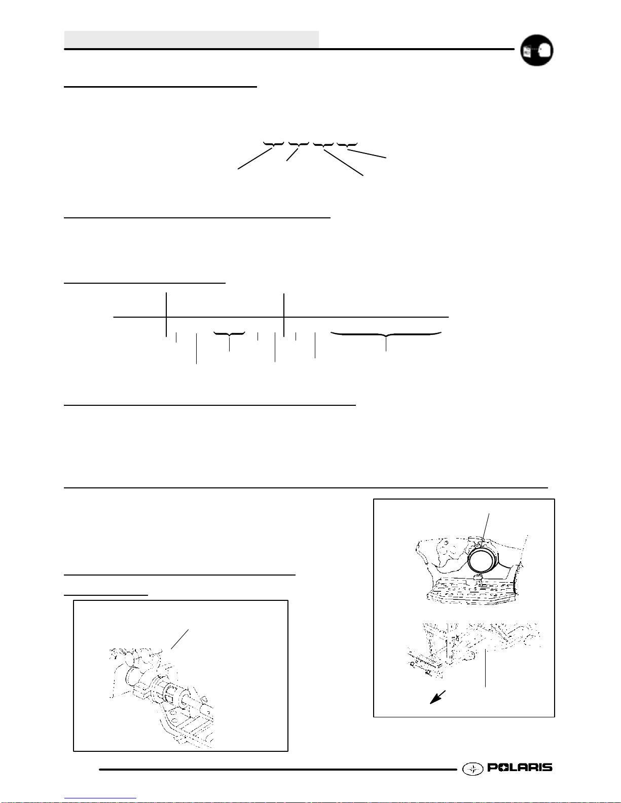
ENGINE SERIAL NUMBER LOCATION
Whenever corresponding about anengine, besure to refer to the engine model numberand serialnumber. This
information can be found on the sticker appliedto the recoil housing on the right side of engine.(A) An additional
number is stamped on the center top of crankcase beneath the cylinder coolant elbow.
MACHINE MODEL NUMBER AND SERIAL NUMBER LOCATION
Themachine modelnumber andserial numberare
important for vehicle identification. The machine
serial number is stamped on the lower left side of
the frame tube.(B)
A
TRANSMISSION I.D. NUMBER
LOCA
TION
The transmission I.D. number is located
on top of the transmission snorkel, right
side of machine.
1.2
Front
B
Page 8
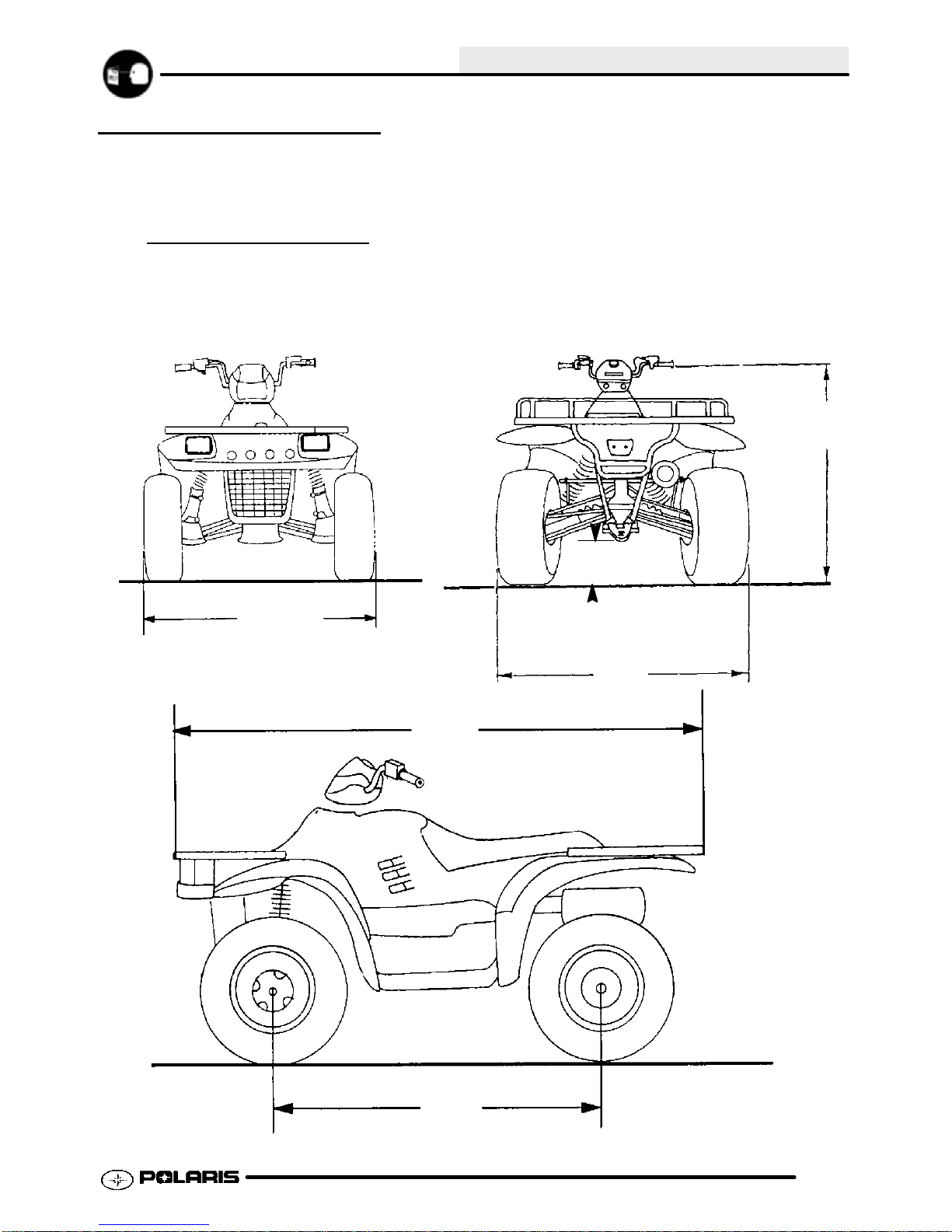
MACHINE DIMENSIONS
SPORTSMAN 400/500
GENERAL INFORMATION
47 in
114 cm
46 in
117 cm
400 --
500 --
11 in
28 cm
46 in
117 cm
81 in
205.7 cm
85 in
216 cm
51 in
128 cm
51 in
129.5 cm
1.3
Page 9

GENERAL INFORMATION
ltitude
Below40
F
+40
Fan
dabov
e
Meter
s
0-180
0
(Feet
)
Above1800
Altitud
e
Meter
s
0-180
0
(Feet
)
180
0-370
0
MODEL: SPORTSMAN 400..........
MODEL NUMBER: A03CH42.
ENGINE MODEL: EH42PLE05..
CARBURETION
Type BST 34 Mikuni................
Main Jet 167.5............
Pilot Jet 40.............
Jet Needle 4GAC33--3...........
Needle Jet Q-0 (829)...........
Throttle Valve #100........
Pilot Screw 2 3/4 Turns Out..........
Pilot Air Jet 160..........
Valve Seat 1.5...........
Float Height 13.0mm (.51I)±1mm.........
Fuel Octane (R+M/2) 87 Non-Oxygenated or.
89 Oxygenated
CLUTCH
Type PVT....................
Belt 3211069.....................
Belt Width (Projected) 1.188I (30.18mm).....
Side Angle (Overall) 26°......
Outside Circumference 40.86 ±.12I....
Center Distance 10±.12I (254.5mm)..........
Clutch Offset 0.5I (12.7mm)............
Secondary Spring Black........
Driven Helix 44-36°.............
Spring Position (Helix) 2....
Spring Position (Sheave) 2..
JETTING CHART
Altitude
Meters
(Feet)
0-1800
(0-6000)
Above 1800
Above (6000)
CLUTCH CHART
A
Meters
(Feet)
0-1800
(0-6000)
1800-3700
(6000-12000)
AMBIENT TEMPERATURE
Below 40°F
Below +5°C
175 167.5
165 160
Shift
Weight Spring Spring Helix
10BH Blue/Green Black 2+2
16 Blue/Green Black 2+2
+40_F and above
+5_C and above
Clutch
Driven Cluthc
Driven
ENGINE
Type 4 Cycle, Single Cyl........................
Displacement 425 cc...............
Bore 3.461I (87.9mm).......................
Stroke 2.756I (70mm).....................
Valve Clearance In/Ex 0.006/0.006I@ TDC on compression.......
Compression Ratio 9.2/1 Full Stroke..........
Cooling Liquid....................
Lubrication Type Dry Sump............
Operating RPM±200 6300 RPM.........
Idle RPM±200 (lights off) 1200 RPM.....
Compression Pressure (Std) ±15%.......
1.4
Page 10
GENERAL INFORMATION
MODEL: SPORTSMAN 400............
MODEL NUMBER: A03CH42...
ENGINE MODEL: EH42PLE05....
ELECTRICAL FLUID Capacity Type
Flywheel I.D. FF95 Fuel Tank 5.25 gals. (19.9L)...... ..........
CDI Marking CU2557 Injector Oil N / A....... .......... .........
**Alternator Output 200 Watts / 250 Watts Coolant 2.25 qts. (2.1L) PP6*. ............
Ignition Timing 30° BTDC@5000RPM±2° Transmission 32 oz. PPS*..... ....... .......
Spark Plug / Gap NGK BKR5E / 0.036I (0.9mm) Gearcase Oil (Front) 4 oz. (120ml) 80-90 GL5... . .
Lights: Head Halogen Gearcase Oil (Center) N / A......
High Beam 50watts Gearcase Oil (Rear) N / A..
Low Beam 27 watts Engine Counter Bal. N / A. . .........
Tail 8.26 watts Engine Oil 2 qts. (1.9L) PP4*........ .......... ..
Brake 26.9 watts Brake (Hand) Dot 3...... .......
Voltage Regulator LR39 Brake (Foot) Dot 3.. ........
Electric Start Standard Front Hubs (AWD) 2.5 oz. (75ml) PDD*....... ...
**Early Build Units Have 200 Watt Altnerantor Shift Selector Box 1 oz. (30ml) PP4*... ..
Lubricant Key
*PP6 Polaris Premium 60/40 Antifreeze/Coolant
*PPS Polaris Premium Synthetic Gear Case Oil
*PP4 Polaris 0W/40 Synthetic Engine Lubricant
*PDD Premium Demand Drive Hub Fluid
SUSPENSION / CHASSIS DRIVE TRAIN
Body Style Gen IV Chain Type Shaft Drive........ .........
Front Suspension MacPherson Strut Gear Reduction-Low 6.69/1.. .
Tow Capacity 1225 lbs. (555.6 kg) Gear Reduction-Rev 5.17/1...... ..
Turning Radius 65I (165.1 cm) Gear Reduction-High 3.34/1.....
Toe Out 1/8I-1/4I (3-6.35 mm) Front Drive Ratio 2/1........... ....
Ground Clearance 11I (27.94 cm) Center Drive Ratio N / A.. ...
Front Vertical Travel 6.7I (17.02 cm) Final Drive Ratio 3.16/1....
Rear Suspension Progressive Rate Independent Brake (Hand) Single Lever, Hyd. Disc... .......
Rear Travel 9.5I (24.13cm) Brake (Auxiliary Foot) Hydraulic........
Rear Shock 2I Twin Tube........
Shock Adjustment Cam..
TIRES
Tire Size - Front 25 x 8 - 12....
Tire Size - Rear 25 x 11 - 12....
Tire Size - Center N / A..
Tire Pressure - F/R 5/5 lbs.
Total Width 46I (116.84 cm)........
Total Length 81I (205.74 cm).......
Total Height 47I (119.38 cm)........
Wheel Base 50.50I (128.27 cm).......
Weight - Dry 697 lbs. (316.4 kg).......
LOAD CAPACITY
Front Rack (Std) 90 lbs......
Rear Rack (Std) 180 lbs.......
Tongue Weight 120 lbs.....
Tow Hitch Std...........
OPTIONAL SUSPENSION SPRINGS
SPRING TYPE SOFT STANDARD FIRM
Rear Compression Spring N/A 7041453-067
Front Strut Spring 7041238-067
Option 61 lb/in.
Standard 100 lb/in.
7041375-067
Standard 64/113 lb/in.
7041519-067
Option 140 lb/in.
7041450-067
Option 101 lb/in.
1.5
Page 11

GENERAL INFORMATION
ltitude
Below40
F
+40
Fan
dabov
e
Meter
s
0-180
0
(Feet
)
Above1800
Altitud
e
Meter
s
0-180
0
(Feet
)
180
0-370
0
MODEL: SPORTSMAN 500 H.O...........
MODEL NUMBER: A03CH50.
ENGINE MODEL: EH50PLE13..
CARBURETION
Type BST 40 Mikuni................
Main Jet 152.5............
Pilot Jet 40.............
Jet Needle 6MGH1--94--3...........
Needle Jet X-6...........
Throttle Valve #120........
Pilot Screw 2 Turns Out..........
Pilot Air Jet 1.3..........
Valve Seat 1.5...........
Float Height 14.7mm (.58I)±1mm.........
Fuel Octane (R+M/2) 87 Non-Oxygenated or.
89 Oxygenated
CLUTCH
Type PVT....................
Belt 3211069.....................
Belt Width (Projected) 1.188I (30.18mm).....
Side Angle (Overall) 26°......
Outside Circumference 40.86 ±.12I....
Center Distance 10±.12I (254.5mm)..........
Clutch Offset 0.5I (12.7mm)............
Secondary Spring White/Yellow........
Driven Helix Compound (EBS).............
Spring Position (Helix) N/A....
Spring Position (Sheave) N/A..
JETTING CHART
Altitude
Meters
(Feet)
0-1800
(0-6000)
Above 1800
Above (6000)
AMBIENT TEMPERATURE
Below 40°F
Below +5°C
157.5 152.5
150 145
CLUTCH CHART
A
Meters
(Feet)
*EBS require no helix/spring adjustment
0-1800
(0-6000)
1800-3700
(6000-12000)
Shift
Weight Spring Spring Helix*
10WH Blue/Green White/Yellow EBS
16 Blue/Green White/Yellow EBS
+40_F and above
+5_C and above
Clutch
Driven Clutch
Driven
ENGINE
Type 4 Cycle, Single Cyl........................
Displacement 499 cc...............
Bore 3.6248I (92mm).......................
Stroke 2.955I (75mm).....................
Valve Clearance In/Ex 0.006/0.006I@ TDC on compression.......
Compression Ratio 10/2 Full Stroke..........
Cooling Liquid....................
Lubrication Type Dry Sump............
Operating RPM±200 6500 RPM.........
Idle RPM±200 (lights off) 1200 RPM.....
Compression Pressure (Std) ±15%.......
1.6
Page 12

GENERAL INFORMATION
MODEL: SPORTSMAN 500 H.O.............
MODEL NUMBER: A03CH50...
ENGINE MODEL: EH50PLE13....
ELECTRICAL FLUID Capacity Type
Flywheel I.D. FF97 Fuel Tank 5.25 gals. (19.9L)...... ..........
CDI Marking CU2574 Injector Oil N / A....... .......... .........
Alternator Output 250 Watts Coolant 2.25 qts. (2.1L) PP6*... ............
Ignition Timing 30° BTDC@5000RPM±2° Transmission 32 oz. PPS*..... ....... .......
Spark Plug / Gap NGK BKR6E / 0.036I (0.9mm) Gearcase Oil (Front) 4 oz. (120ml) 80-90 GL5... . .
Lights: Head Halogen Gearcase Oil (Center) N / A......
High Beam 50watts Gearcase Oil (Rear) N / A..
Low Beam 27 watts Engine Counter Bal. N / A. . .........
Tail 8.26 watts Engine Oil 2 qts. (1.9L) PP4*........ .......... ..
Brake 26.9 watts Brake (Hand) Dot 3...... .......
Voltage Regulator LR39 Brake (Foot) Dot 3.. ........
Electric Start Standard Front Hubs (AWD) 2.5 oz. (75ml) PDD*....... ...
Shift Selector Box 1 oz. (30ml) PP4*... ..
Lubricant Key
*PP6 Polaris Premium 60/40 Antifreeze/Coolant
*PPS Polaris Premium Synthetic Gear Case Oil
*PP4 Polaris 0W/40 Synthetic Engine Lubricant
*PDD Premium Demand Drive Hub Fluid
SUSPENSION / CHASSIS DRIVE TRAIN
Body Style Gen IV Chain Type Shaft Drive........ .........
Front Suspension MacPherson Strut Gear Reduction-Low 6.69/1.. .
Tow Capacity 1225 lbs. (555.6 kg) Gear Reduction-Rev 5.17/1...... .
Turning Radius 65I (165.1 cm) Gear Reduction-High 3.34/1.....
Toe Out 1/8I-1/4I (3-6.35 mm) Front Drive Ratio 2/1........... ....
Ground Clearance 11I (27.94 cm) Center Drive Ratio N / A.. ...
Front Vertical Travel 6.7I (17.02 cm) Final Drive Ratio 3.16/1....
Rear Suspension Progressive Rate Independent Brake (Hand) Single Lever, Hyd. Disc... .......
Rear Travel 9.5I (24.13 cm) Brake ( Auxiliary Foot) Hydraulic........
Rear Shock 2I Twin Tube........
Shock Adjustment Cam..
TIRES
Tire Size - Front 25 x 8 - 12....
Tire Size - Rear 25 x 11 - 12....
Tire Size - Center N / A..
Tire Pressure - F/R 5/5 lbs.
Total Width 46I (116.84 cm)........
Total Length 85I (215.9 cm).......
Total Height 47I (119.38 cm)........
Wheel Base 50.50I (128.27 cm).......
Weight - Dry 697 lbs. (316.4 kg).......
LOAD CAPACITY
Front Rack (Std) 90 lbs......
Rear Rack (Std) 180 lbs.......
Tongue Weight 120 lbs.....
Tow Hitch Std...........
OPTIONAL SUSPENSION SPRINGS
SPRING TYPE SOFT STANDARD FIRM
Rear Compression Spring N/A 7041453-067
Front Strut Spring 7041238-067
Option 61 lb/in.
Standard 100 lb/in.
7041375-067
Standard 64/113 lb/in.
7041519-067
Option 140 lb/in.
7041450-067
Option 101 lb/in.
1.7
Page 13

GENERAL INFORMATION
PUBLICATION NUMBERS
Year Model Model No. Owner’s
Manual PN
2003 Sportsman400 A03CH42 9917492 9917537 9917538
2003 Sportsman500 A03CH50 9917492 9917541 9917542
When ordering service parts be sure to use the correct parts manual.
FRAME COLOR - (All) P067 Medium Gloss Black 9440 / 8520147.
Order direct from Midwest Industrial Coatings (952-942-1840). Mix as directed.
Parts
Manual PN
Micro Fiche PN
COLD WEATHER KITS FOR 4 CYCLE ATVS
Oil Tank Cover -- (PN 2871874)
Engine Heater -- (PN 2871507)
REPLACEMENT KEYS
Replacement keys can be made from the original
key. To identify which series the key is, take the
first two digits on the original key and refer to the
chart to the right for the proper part number.
Parts
31XX
Key Series
Number
Series # Part Number
20 4010278
21 4010278
22 4010321
23 4010321
27 4010321
28 4010321
31 4110141
32 4110148
67 4010278
68 4010278
1.8
Page 14

GENERAL INFORMATION
STANDARD TORQUE SPECIFICATIONS
The following torque specifications are to be used as a general guideline. There are exceptions in the steering,
suspension, and engine areas. Always consult the exploded views in each manual section for torque values of
fasteners before using standard torque.
Bolt Size Threads/In Grade 2 Grade 5 Grade 8
Torque in. lbs. (Nm)
#10 - 24 27 (3.1) 43 (5.0) 60 (6.9).............. ................ ..............
#10 - 32 31 (3.6) 49 (5.6) 68 (7.8).............. ................ ..............
Torque ft. lbs. (Nm)*
1/4 - 20 5 (7) 8 (11) 12 (16).............. .................. ................
1/4 - 28 6 (8) 10 (14) 14 (19).............. .................. ..............
5/16 - 18 11 (15) 17 (23) 25 (35).............. ................ ..............
5/16 - 24 12 (16) 19 (26) 29 (40).............. ................ ..............
3/8 - 16 20 (27) 30 (40) 45 (62).............. ................ ..............
3/8 - 24 23 (32) 35 (48) 50 (69).............. ................ ..............
7/16 - 14 30 (40) 50 (69) 70 (97).............. ................ ..............
7/16 - 20 35 (48) 55 (76) 80 (110).............. ................ ..............
1/2 - 13 50 (69) 75 (104) 110 (152).............. ................ .............
1/2 - 20 55 (76) 90 (124) 120 (166).............. ................ .............
Metric
6 x 1.0 72-78 In. lbs.
8 x 1.25 14-18 ft. lbs.
10 x 1.25 26-30 ft. lbs.
*To convert ft. lbs. to Nm multiply foot pounds by .1.382
*To convert Nm to ft. lbs. multiply Nm by .7376.
SPECIFIC TORQUE VALUES OF FASTENERS
Refer to exploded views in the appropriate sectionTorque Conversions
1.9
Page 15

GENERAL INFORMATION
DECIMAL EQUIVALENTS
1/64 .0156.........................
1/32 .0312 1 mm = .0394²................... ................
3/64 .0469.........................
1/16 .0625..............
5/64 .0781 2 mm = .0787²......................... ................
3/32 .0938...................
7/64 .1094 3 mm = .1181²....................... ................
1/8 . 1250. .......
9/64 .1406.........................
5/32 .1563 4 mm = .1575²................... ................
11/64 .1719........................
3/16 .1875 5 mm = .1969².............. ................
13/64 .2031........................
7/32 .2188...................
15/64 .2344 6 mm = .2362²........................ ................
1/4 .25..........
17/64 .2656 7 mm = .2756²........................ ................
9/32 .2813...................
19/64 .2969........................
5/16 .3125 8 mm = .3150².............. ................
21/64 .3281........................
11/32 .3438 9 mm = .3543².................. ................
23/64 .3594........................
3/8 .375..........
25/64 .3906 10 mm = .3937²........................ ................
13/32 .4063..................
27/64 .4219 11 mm = .4331²........................ ................
7/16 .4375..............
29/64 .4531........................
15/32 .4688 12 mm = .4724².................. ................
31/64 .4844........................
1/2 .5 13 mm = .5118”.......... ...................
33/64 .5156........................
17/32 .5313..................
35/64 .5469 14 mm = .5512²........................ ................
9/16 .5625..............
37/64 .5781 15 mm = .5906²........................ ................
19/32 .5938..................
39/64 .6094........................
5/8 .625 16 mm = .6299².......... .................
41/64 .6406........................
21/32 .6563 17 mm = .6693².................. ................
43/64 .6719.......................
11/16 .6875.............
45/64 .7031 18 mm = .7087²........................ ................
23/32 .7188..................
47/64 .7344 19 mm = .7480²........................ ................
3/4 .75..........
49/64 .7656........................
25/32 .7813 20 mm = .7874².................. ................
51/64 .7969........................
13/16 .8125 21 mm = .8268²............. ................
53/64 .8281........................
27/32 .8438..................
55/64 .8594 22 mm = .8661²........................ ................
7/8 .875..........
57/64 .8906 23 mm = .9055²........................ ................
29/32 .9063..................
59/64 .9219.......................
15/16 .9375 24 mm = .9449²............. ................
61/64 .9531........................
31/32 .9688 25 mm = .9843”.................. ................
63/64 .9844........................
1 1.0............
1.10
Page 16

GENERAL INFORMATION
CONVERSION TABLE
Unit of Measure Multiplied by Converts to
ft. lbs. x 12 = in. lbs.
in. lbs. x .0833 = ft. lbs.
ft. lbs. x 1.356 = Nm
in. lbs. x .0115 = kg-m
Nm x .7376 = ft.lbs.
kg-m x 7.233 = ft. lbs.
kg-m x 86.796 = in. lbs.
kg-m x 10 = Nm
in. x 25.4 =mm
mm x .03937 = in.
in. x 2.54 = cm
mile (mi.) x 1.6 = km
km x .6214 = mile (mi.)
Ounces (oz) x 28.35 = Grams (g)
Fluid Ounces (fl. oz.) x 29.57 = Cubic Centimeters (cc)
Cubic Centimeters (cc) x .03381 = Fluid Ounces (fl. oz.)
Grams (g) x 0.035 = Ounces (oz)
lb. x .454 = kg
kg x 2.2046 = lb.
Cubic inches (cu in) x 16.387 = Cubic centimeters (cc)
Cubic centimeters (cc) x 0.061 = Cubic inches (cu in)
Imperial pints (Imp pt) x 0.568 = Liters (l)
Liters (l) x 1.76 = Imperial pints (Imp pt)
Imperial quarts (Imp qt) x 1.137 = Liters (l)
Liters (l) x 0.88 = Imperial quarts (Imp qt)
Imperial quarts (Imp qt) x 1.201 = US quarts (US qt)
US quarts (US qt) x 0.833 = Imperial quarts (Imp qt)
US quarts (US qt) x 0.946 = Liters (l)
Liters (l) x 1.057 = US quarts (US qt)
US gallons (US gal) x 3.785 =Liters (l)
Liters (l) x 0.264 = US gallons (US gal)
Pounds - force per square inch (psi) x 6.895 = Kilopascals (kPa)
Kilopascals (kPa) x 0.145 = Pounds - force per square inch (psi)
Kilopascals (kPa) x 0.01 = Kilograms - force per square cm
Kilograms - force per square cm x 98.1 = Kilopascals (kPa)
p (3. 14) xR2x H (height) = Cylinder Volume
°C to °F: 9 (°C + 40) ¸ 5-40=°F
°F to °C: 5 (°F + 40) ¸ 9-40=°C
1.11
Page 17
GENERAL INFORMATION
SAE TAP DRILL SIZES
Thread Size Drill Size Thread Size Drill Size
#0-80 3/64
#1-64 53
#1-72 53
#2-56 51
#2-64 50
#3-48 5/64
#3-56 45
#4-40 43
#4-48 42
#5-40 38
#5-44 37
#6-32 36
#6-40 33
#8-32 29
#8-36 29
#10-24 24
#10-32 21
#12-24 17
#12-28 4.6mm
1/4-20 7
1/4-28 3
5/16-18 F
5/16-24 I
3/8-16 O
3/8-24 Q
7/16-14 U
7/16-20 25/64
1/2-13 27/64
1/2-20 29/64
9/16-12 31/64
9/16-18 33/64
5/8-11 17/32
5/8-18 37/64
3/4-10 21/32
3/4-16 11/16
7/8-9 49/64
7/8-14 13/16
1-8 7/8
1-12 59/64
1 1/8-7 63/64
1 1/8-12 1 3/64
1 1/4-7 1 7/64
1 1/4-12 1 11/64
1 1/2-6 1 11/32
1 1/2-12 1 27/64
1 3/4-5 1 9/16
1 3/4-12 1 43/64
2-4 1/2 1 25/32
2-12 1 59/64
2 1/4-4 1/2 2 1/32
2 1/2-4 2 1/4
2 3/4-4 2 1/2
3-4 2 3/4
METRIC TAP DRILL SIZES
Tap Size Drill Size Decimal Equivalent Nearest Fraction
3 x .50
3 x .60
4 x .70
4 x .75
5 x .80
5 x .90
6 x 1.00
7 x 1.00
8 x 1.00
8 x 1.25
9 x 1.00
9 x 1.25
10 x 1.25
10 x 1.50
11 x 1.50
12 x 1.50
12 x 1.75
#39
3/32
#30
1/8
#19
#20
#9
16/64
J
17/64
5/16
5/16
11/32
R
3/8
13/32
13/32
1.12
0.0995
0.0937
0.1285
0.125
0.166
0.161
0.196
0.234
0.277
0.265
0.3125
0.3125
0.3437
0.339
0.375
0.406
0.406
3/32
3/32
1/8
1/8
11/64
5/32
13/64
15/64
9/32
17/64
5/16
5/16
11/32
11/32
3/8
13/32
13/32
Page 18

GENERAL INFORMATION
GLOSSARY OF TERMS
ABDC: After bottom dead center.
ACV: Alternating current voltage.
Alternator: Electrical generator producing voltage alternating current.
ATDC: After top dead center.
BBDC: Before bottom dead center.
BDC: Bottom dead center.
BTDC: Before top dead center.
CC: Cubic centimeters.
Center Distance: Distance between center of crankshaft and center of driven clutch shaft.
Chain Pitch: Distance between chain link pins (No. 35 = 3/8² or 1 cm). Polaris measures chain length in number of
pitches.
CI: Cubic inches.
Clutch Buttons: Plastic bushings which transmit rotation of the clutch to the movable sheave in thedrive and driven
clutch.
ClutchOffset: Driveand drivenclutches areoffset sothat drivebelt willstay nearlystraight asitmovesalongtheclutch
face.
Clutch Weights: Threelevers in the drive clutch which relative to their weight, profile and engine RPM causethe drive
clutch to close.
Condenser/Capacitor: A storage reservoir for DC voltage.
Crankshaft Run-Out: Run-out or “bend” of crankshaft measured with a dial indicator while crankshaft is supported
between centers on V blocks or resting in crankcase. Measure at various points especially at PTO.
DCV: Direct current voltage.
Dial Bore Gauge: A cylinder measuring instrument which uses a dial indicator. Good for showing taper and
out-of-round in the cylinder bore.
Electrical Open: Open circuit. An electrical circuit which isn’t complete.
Electrical Short: Short circuit. An electrical circuit which is completed before the current reaches the intended load.
(i.e. a bare wire touching the chassis).
End Seals: Rubber seals at each end of the crankshaft.
Engagement RPM: Engine RPM at which the drive clutch engages to make contact with the drive belt.
ft.: Foot/feet.
Foot Pound: Ft. lb. A force of one pound at the end of a lever one foot in length, applied in a rotational direction.
g: Gram. Unit of weight in the metric system.
gal.: Gallon.
HP: Horsepower.
ID: Inside diameter.
in.: Inch/inches.
Inch Pound: In. lb. 12 in. lbs. = 1 ft. lb.
kg/cm2: Kilograms per square centimeter.
kg-m: Kilogram meters.
Kilogram/meter: A force of one kilogram at the end of a lever one meter in length, applied in a rotational direction.
l or ltr: Liter.
lbs/in2: Pounds per square inch.
Left Side: Always referred to based on normal operating position of the driver.
1.13
Page 19

GENERAL INFORMATION
GLOSSARY OF TERMS
m: Meter/meters.
Mag: Magneto.
Magnetic Induction: As a conductor (coil) is moved through a magnetic field, a voltage will be generated in the
windings. Mechanical energy is converted to electrical energy in the stator.
mi.: Mile/miles.
mm: Millimeter. Unit of length in the metric system. 1mm = approximately .040².
Nm: Newton meters.
OD: Outside diameter.
Ohm: The unit of electrical resistance opposing current flow.
oz.: Ounce/ounces.
Piston Clearance: Total distance between piston and cylinder wall.
psi.: Pounds per square inch.
PTO: Power take off.
PVT: Polaris Variable Transmission (Drive Clutch System)
qt.: Quart/quarts.
Regulator: Voltage regulator. Regulates battery charging system output at approx. 14.5 DCV as engine RPM
increases.
Reservoir Tank: The fill tank in the liquid cooling system.
Resistance: Inthemechanicalsense,friction or load. Intheelectricalsense, ohms. Bothresult inenergyconversionto
heat.
Right Side: Always referred to based on normal operating position of the driver.
RPM: Revolutions per minute.
Secondary Clutch: Driven clutch on chaincase or jackshaft.
SeizedPiston: Gallingofthesidesof a piston. Usuallythere is atransfer ofaluminumfrom the pistononto thecylinder
wall. Possible causes: 1) improper lubrication; 2) excessive temperatures; 3) insufficient piston clearance; 4) stuck
piston rings.
Stator Plate: The plate mounted under the flywheel supporting the battery charging coils.
TDC: Top dead center. Piston’s most outward travel from crankshaft.
Volt: The unit of measure for electrical pressure of electromotive force. Measured by a voltmeter in parallel with the
circuit.
Watt: Unit of electrical power. Watts = amperes x volts.
WOT: Wide open throttle.
1.14
Page 20

CHAPTER 2
MAINTENANCE
Periodic Maintenance Chart 2.2-2.3...............
Pre-Ride Inspection 2.3......................
Recommended Lubricants and Capacities 2.4...
Lubricant and Maintenance Product Numbers 2.5
Special Tools 2.6--2.7............................
Lubrication Charts 2.7-2.8........................
Transmission Lubrication 2.9..................
Front Gearcase Lubrication 2.9--2.10................
Transmission Linkage Adjustment 2.10-2.11..........
Carburetor Adjustments 2.11-2.13...................
MAINTENANCE
2
Fuel System 2.13-2.14.............................
Compression Test 2.15........................
Battery Maintenance 2.15--2.16......................
Electrical 2.16................................
Coolant System Maintenance 2.17--2.18..............
Air Filter Service 2.18--2.20.........................
Air Box Sediment Tube Service 2.20............
Breather Filter 2.20...........................
Recoil Housing 2.20...........................
Oil Change/Filter 2.21-2.23.........................
Valve Clearance 2.23-2.24.........................
Steering and Toe Alignment 2.24-2.26...............
Front Hub Maintenance 2.26--2.27...................
Exhaust System Maintenance 2.27--2.28.............
Brake System Service 2.28-2.29....................
Suspension Service 2.29......................
Controls 2.29.................................
Wheel Removal/Installation 2.30................
Tire Inspection 2.31...........................
2.1
Page 21

MAINTENANCE
PERIODIC MAINTENANCE
CHART
Inspection, adjustment and lubrication intervals of important components is listed in the following chart.
Maintenance intervals are based upon average riding conditions and a vehicle speed of approximately 10 mph.
Inspect, clean, lubricate, adjust or replace parts as necessary. NOTE: Inspection may reveal the need for
replacement parts. Always use genuine Polaris parts.
H CAUTION: Due to the nature of these adjustments, it is recommended that service be performed by
an authorized Polaris dealer.
" Vehicles subjected to severe use(operation in wet or dusty areas, low speed heavy load operation,
prolonged idle) should be inspected and serviced more frequently. For engine oil, short trip cold
weather riding also constitutes severe use. Pay special attention tooil level. A rise in oil level in cold weather
can indicate moisture collecting in the oil tank (500). Change oil immediately if oil level begins to rise.
E Emission Control System Service (California).
Frequency
(Whichever comes first)
Item Hours Calendar Miles
(Km)
Engine Oil - Level/Change 100 hrs 6 months 1000 (1600) Check Level Daily; Break In service at 1 month
E"
Oil Filter 100 hrs 6 months 1000 (1600) Replace with oil change
E
Air Filter - Foam Pre-Cleaner Daily Daily Inspect-Clean & oil more often in dirty conditions.
E"
Air Filter - Main Element Weekly Weekly Inspect - Replace if necessary
E"
" Air Box Sediment Tube - Daily Drain deposits whenever visible
" Engine Breather Filter 20 hrs Monthly 200 (320) Inspect and replace if necessary
" Oil Tank Vent Hose 100 hrs 12 months 1000 (1600) Inspect hose routing /hose condition
Valve Clearance 100 hrs 12 months 1000 (1600) Inspect/Adjust
EH
Idle Speed As required As required Adjust
E
H Throttle Cable / ETC Switch 50 hrs 6 months 500 (800) Inspect -Adjust, Lubricate, Replace if necessary
Choke (Enricher) Cable 50 hrs 6 months 500 (800) Inspect -Adjust, Lubricate, Replace if necessary
Carburetor Float Bowl 50 hrs 6 months 500 (800) Drain bowl periodically and prior to storage
Carburetor Air Intake Ducts/Flange 50 hrs 6 months 500 (800) Inspect all ducts for proper sealing/air leaks
Fuel System 100 hrs 12 months 1000 (1600) Check for leaks at tank cap, lines, fuel valve, filter,
EH
Fuel Filter 100 hrs 12 months 1000 (1600) Replace filter annually
EH
Coolant/Level Inspection Daily Daily Replace engine coolant every 2 years
Coolant Strength / Pressure Test
System
Radiator 100 hrs 12 months 1000 (1600) Inspect / Clean external surface
Cooling System Hoses 100 hrs 12 months 1000 (1600) Inspect
Engine Mounts 100 hrs 12 months 1000 (1600) Inspect
Drain Recoil Housing Weekly Weekly More often if operating in wet environment
Exhaust Muffler / Pipe 100 hrs 12 months 1000 (1600)
100 hrs 6 months 1000 (1600) Inspect strength seasonally; Pressure test sys-
pump & carburetor. Replace lines every 2 years.
tem annually
ELECTRICAL
Spark Plug 100 hrs 12 months 1000 (1600) Inspect - Replace if necessary
E
Wiring 100 hrs 12 months 1000 (1600) Inspect for abrasion, routing, security
Ignition Timing 100 hrs 12 months 1000 (1600) Inspect
Battery 20 hrs Monthly 200 (320) Check terminals; Clean; Check fluid level
Headlight Aim As required As required Adjust if Necessary
Remarks
2.2
Page 22
MAINTENANCE
Headlamp Inspection Daily Daily Check operation daily; Apply Nyogelt Grease
Tail Lamp Inspection Daily Daily Check Operation Daily; Apply Nyogelt Grease
to connector when lamp is replaced
to socket when lamp is replaced
CHASSIS
Frequency
(Whichever comes first)
Item Hours Calendar Miles
(Km)
" General Lubrication 50 hrs 3 months 500 (800) Lubricate All Fittings, Pivots, Cables, Etc.
" Front Hubs/Fluid Check 50 hrs 6 months 500 (800) Check monthly
" Front Hubs/Fluid Change 100hrs 12 months 1000 (1600) Check monthly
" Front Gearcase Lubricant 100 hrs 12 months 1000 (1600) Inspect Monthly; Change Annually
Drive Belt 50 hrs 6 months 500 (800) Inspect - Adjust, Replace if Necessary
Clutches (Drive And Driven) 100 hrs 12 months 1000 (1600) Inspect, Clean
" Transmission Oil Level 25 hrs Monthly 250 (400) Inspect Monthly; Change Annually
Shift Linkage 50 hrs 6 months 500 (800) Inspect,Lubricate, Adjust
Shift Selector Box 200 hrs 24 months 2000 (3200) Change Lubricant Every Two Years
H Steering 50 hrs 6 months 500 (800) Inspect Daily, Lubricate
H Toe Adjustment As required As required Periodic Inspection, Adjust When Parts are Re-
placed
" Front Suspension 50 hrs 6 months 500 (800) Inspect - Lubricate
" Rear Suspension 50 hrs 6 months 500 (800) Inspect - Lubricate
Tires Pre-ride Pre-ride Inspect Daily, Pre-Ride Inspection Item
H Brake Fluid 200 hrs 24 months 2000 (3200) Change Every Two Years
" Brake Fluid Level Pre-ride Pre-ride Inspect Daily, Pre-Ride Inspection Item
" Brake Lever Travel Pre-ride Pre-ride Inspect Daily, Pre-Ride Inspection Item
H Brake Pad Wear 10 hrs Monthly 100 (160) Inspect Periodically
Auxiliary Brake Adjustment As required As required Inspect Deflection Daily; Adjust
Brake System Pre-ride Pre-ride Pre-Ride Inspection Item
Wheels Pre-ride Pre-ride Pre-Ride Inspection Item
Frame Nuts, Bolts, Fasteners Pre-ride Pre-ride Pre-Ride Inspection Item
Remarks
PRE-RIDE / DAILY INSPECTION
Perform the following pre-ride inspection daily, and when servicing the vehicle at each scheduled maintenance.
S Tires - check condition and pressures
S Fuel and oil tanks - fill both tanks to their proper level; Do not overfill oil tank
S All brakes - check operation and adjustment (includes auxiliary brake)
S Throttle - check for free operation and closing
S Headlight/Taillight/Brakelight - check operation of all indicator lights and switches
S Engine stop switch - check for proper function
S Wheels - check for tightness of wheel nuts and axle nuts; check to be sure axle nuts are
secured by cotter pins
S Air cleaner element - check for dirt; clean or replace
S Steering - check for free operation noting any unusual looseness in any area
S Loose parts - visually inspect vehicle for any damaged or loose nuts, bolts or fasteners
S Engine coolant - check for proper level at the recovery bottle
2.3
Page 23

MAINTENANCE
RECOMMENDED LUBRICANTS - QUICK REFERENCE
LUBRICANTS AND MAINTENANCE PRODUCT PART NUMBERS ARE LISTED ON PAGE 2.5
Item
Engine Oil Polaris Premium 4
Synthetic, 0W--40 (PN
2871567)
Transmission Polaris Synthetic Gear
Case Lubricant (PN
2871478)
Front Gear Case Premium Front Gearcase
Fluid (PN2871653) or GL5
80-90 Gear Lube
Gear Shift Selector
Box
Coolant Level Polaris Premium 60/40
Front Hubs Premium Demand Drive
Brake Fluid Polaris DOT 3 Brake Fluid
Polaris 0W--40 Synthetic
Engine Lubricant (PN
2871281)
Pre-mixed Antifreeze/
Coolant (PN 2871323) or
a 50/50 mixture high quality antifreeze/coolant and
distilled water
Hub Fluid (PN 2871654)
(PN 2870990)
Type Notes See
Pages
Add to proper level on dipstick. 2.21--2.22
Refer to procedures outlined later in this
chapter.
Refer to procedures outlined later in this
chapter.
Oil in selector box should be at the center
line of the shift selector plungers. Do not
overfill or the selector may hydro-lock.
Fill reservoir tank to full line. Add if necessary. If reservoir was empty or extremely
low, allow engine and cooling system to
cool completely and check level in radiator. Fill to top of filler neck.
Fill hub at 4:00 or 8:00 position until fluid
trickles out. Do not force fluid into hub.
-Fill to indicated level inside reservoir. 2.28
2.9
2.9--2.10
8.4
2.18
2.27
COLD WEATHER KITS FOR 4 CYCLE ATV’S
Oil Tank Cover -- (PN 2871874)
Engine Heater -- (PN 2871507)
2.4
Page 24

MAINTENANCE
POLARIS LUBRICANTS,MAINTENANCE AND SERVICE PRODUCTS
Part No. Description
Engine Lubricant
2870791 Fogging Oil(12 oz. Aerosol)
2871098 Premium2 Cycle Engine Oil (Quart) (12
Count)
2871281 Engine Oil (Quart) Premium 4 Synthetic
0W--40 (4--Cycle) (12 Count)
2871844 Engine Oil (Gallon) Premium 4 Synthetic
0W--40 (4--Cycle) (4 Count)
2871567 Engine Oil (16 Gallon) Premium 4
Synthetic0W--40 (4--Cycle)
Gearcase / Transmission Lubricants
2873603 Premium Synthetic Gearcase Lubricant (1
Gal.)(4 Count)
2873602 Premium Synthetic Gearcase Lubricant
(12 oz. bottle) (12 Count)
2871653 Premium Front Gearcase Fluid (8 oz.)(12
Count)
2871653 Premium Front Gearcase Fluid(2.5 Gal)
(2 Count)
2870465 Oil Pump for 1 Gallon Jug
2871654 Premium Drive Hub Fluid (8 oz.) (12
Count)
2872277 Premium Drive Hub Fluid (2.5 gal.) (2
Count)
2871653 Angle Drive Fluid (8 oz.)
Grease / Specialized Lubricants
2871322 Premium All Season Grease (3 oz.
cartridge) (24 Count)
2871423 Premium All Season Grease (14 oz.
cartridge) (10 Count)
2871460 StarterDrive Grease (12 Count)
2871515 PremiumU-Joint Lube (3 oz.)(24 Count)
2871551 Premium U-Joint Lube (14 oz.)(10 Count)
2871312 Grease Gun Kit
2871329 Dielectric Grease (Nyogelt)
Coolant
2871323 60/40 Coolant (Gallon) (6 Count)
2871534 60/40Coolant (Quart) (12 Count)
Additives / Sealants / Thread Locking Agents /
Misc.
2870585 Loctitet PrimerN, Aerosol, 25 g
2871956 Loctitet Thread Sealant 565 (50 ml.) (6
Count)
2871949 Loctitet Threadlock242 (50ml.) (10
Count)
2871950 Loctitet Threadlock 242 (6 ml.) (12
Count)
2871951 Loctitet Threadlock262 (50ml.) (10
Count)
2871952 Loctitet Threadlock 262 (6 ml.) (12
Count)
2871953 Loctitet Threadlock 271 (6 ml.) (12
Count)
Part No. Description
2871954 Loctitet Threadlock 271 (36 ml.) (6
Count)
2870584 Loctitet 680-Retaining Compound (10
ml.)
2870587 Loctitet 518 Gasket Eliminator / Flange
Sealant (50 ml.) (10 Count)
2872113 Disk Brake Quiet(12 oz.) (12 Count)
2871326 Premium Carbon Clean (12 oz.) (12
Count)
2870652 Fuel Stabilizer (16 oz.) (12 Count)
2871957 Black RTV Silicone Sealer (3 oz. tube)
(12 Count)
2871958 Black RTV Silicone Sealer (11 oz.
cartridge) (12 Count)
2870990 DOT3 Brake Fluid (12 Count)
2872113 Disc Brake Quiet, Aerosol, (9 oz.) (12
Count)
2871557 Crankcase Sealant, 3-Bond 1215 (5oz.)
2872893 Engine Degreaser (12oz.) (12 Count)
NOTE: The number count indicated by each part
number in the table above indicates the number of
units that are shipped with each order.
NOTE: Each item can be purchased separately at
your local Polaris dealer.
2.5
Page 25

MAINTENANCE
SPECIAL TOOLS
PART NUMBER TOOL DESCRIPTION CHAPTER TOOL USED IN
PA--44689 Valve Clutch Adjuster 2
2872105 Water Pump Mechanical Seal Puller 2
8712100 or 8712500 Tachometer 2,10
2200634 Valve Seat Reconditioning Kit 3
2870390 Piston Support Block 3
2871043 Flywheel Puller 3
2871283 Crankshaft/Water Pump Seal Install Kit 3
5131135 WaterPump Install Kit 3
2870569 Crankshaft Truing Stand 5
2872314 CarburetorFloat Adjustment Tool 4
2870975 Mity Vact Pressure TestTool 3,4, 9
2870871 Ball Joint Replacement Tool 5
2870872 Shock Spanner Wrench 2, 5
2870623 Shock Absorber Spring Compression Tool 5
2871572 Strut Rod Wrench 5
2871573 LH Strut Spring Compressor 5
2871574 RH Strut Spring Compressor 5
7052069 Charging Needle 5
2200421 Gas Shock Recharging Kit 5
2871352 Shock Rod Holding Tool 5
2871351 Foxt Shock IFP Depth Tool 5
2870506 Clutch Puller 6
9314177 Clutch Holding Wrench 6
2871358 Clutch Holding Fixture 6
2870341 Drive Clutch Spider Removal and Install Tool 6
2870654 Clutch OffsetAlignment Tool 6
2870913 Driven Clutch Puller 6
2870910 Roller Pin Tool 6
2871226 Clutch Bushing ReplacementTool Kit 6
2870386 Piston Pin Puller 6
2872292 EBS ClutchAlignment Tool 6
2201379 EBS Bushing Replacement Kit 6
8700220 Clutch Compression Tool 6
2871025 Clutch Bushing ReplacementTool Kit 6
2871199 Seal Sleeve Installation Tool Kit 5, 7
2870888 Hilliard Clutch Garter Spring Installation Tool 7
2872608 Roller Pin Removal Tool 7
8700226 CV Boot Clamp Pliers 7
2871701 (Part of 2871702 Kit) 2 1/8 inch Wrench 8
2871697 (Part of 2871702 Kit) Center Drive Bushing Tool 8
2871695 (Part of 2871702 Kit) Backlash Setting Tool 8
2871698 (Part of 2871702 Kit) Rear OutputSeal Driver 8
2871699 (Part of 2871702 Kit) Rear Driveshaft Seal Guide 8
2871282 BearingSeal Driver (50 mm) 8
PV--43568 Fluket77 DigitalMultimeter 10
2870630 TimingLight 10
2870836 Battery Hydrometer 10
2.6
Page 26

MAINTENANCE
SPECIAL TOOLS, CONT’D
2460761 Hall Sensor Probe Harness 10
2871745 Static Timing Light Harness 10
NOTE: Polaris dealers can order the tools listed above through their Polaris Special Service Tools catalog.
LUBRICATION
Ill.
#
Item
1 Engine Oil
2 Transmis-
sion
3 Brake Fluid
4 Front Gear-
case Oil
Lube Required Method Frequency*
Polaris 0W--40
Synthetic (PN
2871567)
Polaris Synthetic
Gear Case Lubricant
(PN 2871478)
Polaris DOT 3 Brake
Fluid (PN 2870990)
Premium Front Gearcase Lube (PN
2871653)
Add oil to proper level. Change after 1st month, 6 months or 100
hours thereafter; Change more often(25-50
hours) in extremely dirty conditions, or short
trip cold weather operation.
Add lube to FULL level on dipstick. Change annually ©
Fill master cylinder reservoirto indicated level inside reservoir.
Add to bottom of fill plug threads. Change annually©
As required. Change fluidevery 2 years.
* More often under severe use, such as operated in water or under severe loads.
¡ Semi-annually or 50 hours of operation (refer to Maintenance Schedule for additional information)
More often under severe conditions (operating in water or hauling heavy loads)
© Annually or 100 hours of operation (refer to Maintenance Schedule for additional information)
More often under severe conditions (operating in water or hauling heavy loads)
¢ Grease conforming to NLGI No. 2, such as Polaris Premium All Season Grease, Conoco Superlube M or
Mobilegrease Special
Transmission Dipstick
Dipstick
Filter
1. Engine Oil and Filter
Master Cylinder
Reservoir
3. Brake Fluid (Left hand Master Cylinder)
Full
OperatingRange
2. Transmission
Fill Plug
4. Front Gear Case Fill Plug
2.7
Page 27

MAINTENANCE
LUBRICATION, CONT.
6. Front Drive
AxleU-Joint
5. Demand 4 Hubs
7. Front Prop Shaft
U-Joint
Ill.
#
Item Lube Required Method Frequency*
5 Demand 4 Hubs
- All Wheel Drive
6 Front Drive Axle
“U” Joints
7 U-Joints - Front
Prop Shaft
8 Propshaft Yoke
8. Propshaft Yoke
(3 pumps max.)
Polaris Demand
Drive Hub Fluid (PN
2871654)
Polaris U-Joint
Grease¢ (PN
2871551)
Premium U-Joint
Grease ¢
(PN 2871551)
Premium U-Joint
Grease ¢
(PN 2871551)
Remove filler hole screw in hubs. Rotate wheels to
4 or 8 O’clockposition. If lubricantis not visible add
until it flows from fillerhole. Reinstall screw.
Locate grease fittingand greasewith grease gun. Semi-annually
Locate Fittingsand Grease Semi-annual-
Locate fittings and grease - 3 pumps maximum Annually©
* More often under severe use, such as operated in water or under severe loads.
4 or 8 O’clock position- (end view)
Semi-annually
¡
¡
ly¡
¡ Semi-annually or 50 hours of operation (refer to Maintenance Schedule for additional information)
More often under severe conditions (operating in water or hauling heavy loads)
© Annually or 100 hours of operation (refer to Maintenance Schedule for additional information)
More often under severe conditions (operating in water or hauling heavy loads)
¢ Grease conforming to NLGI No. 2, such as Polaris Premium All Season Grease, Conoco Superlube M or
Mobilegrease Special
2.8
Page 28

MAINTENANCE
TRANSMISSION
LUBRICA
The transmission lubricant level should be checked
and changed in accordance with the maintenance
schedule.
SPORTSMAN 400/500 TRANSMISSION
S Be sure vehicle is level before
proceeding.
S Check vent hose to be sure it is
routed properly and unobstructed.
TRANSMISSION SPECIFICATIONS
Specified Lubricant:
Polaris Premium Synthetic Gearcase Lubricant
PN 2871477 (Gallon) PN 2871478 (12 oz..)
Capacity:
Drain Plug:
14 ft. lbs. (19.4 Nm)
TION
Dipstick Location
At change: Approx. 20 oz.....
To change lubricant:
1. Remove skid plate (if necessary).
2. Place a drain pan beneath the transmission oil
drain plug area.
3. Remove thedrain plugandwipethemagneticend
clean to remove accumulated metallic filings.
4. After the oil has drained completely, install a new
sealing washer and install the drain plug. Torque
to 14 ft. lbs. (19 Nm).
5. Add the properlubricant through the dipstick hole
until the oil level is between the upper and lower
limits. Do not overfill.
6. Check for leaks.
7. Reinstall skid plate if removed in Step 1.
FRONT GEARCASE
LUBRICA
The gearcase lubricant level should be checked and
changed in accordance with the maintenance
schedule.
S Besurevehicleislevelbefore proceeding.
S Check vent hose to be sure it is routed
properly and unobstructed.
S The correct gearcase lubricant to use is
Polaris Premium GL5 80-90 Gear Lube
(PN 2871653)
FRONT GEARCASE SPECIFICATIONS
Specified Lubricant:
Polaris Front Gearcase Lube (PN
2871653)
Capacity:
(120ml.)
TION
...Or API GL5 80-90 Gearlube
4.0 Oz............
Full
To check the level:
1. Remove dipstick and wipe clean.
2. Reinstall dipstick completely, remove and check
the level. Add the proper lubricant as required to
bring level into operating range as shown.
Operating
Range
Drain Plug / Fill Plug Torque:
14 ft. lbs. (19.4 Nm)
To check the level:
1. The front gearcase lubricant level
checked
The gearcase must be drained and re-filled with
the proper amount of lubricant. Refer to
procedure below.
To change lubricant:
1. Remove gearcase drain plug located on the
bottom and drain oil. Catch and discard used oil
properly.
with a dipstick or by visual reference.
cannot be
2.9
Page 29

MAINTENANCE
2. Clean and reinstall drain plug using a newsealing
washer.
3. Remove fill plug.
4. Add proper amount of lubricant.
5. Install fill plug. Check for leaks.
Make sure vent
is unobstructed
Fill plug
Drain Plug
Drain plug
TRANSMISSION GEARSHIFT
LINKAGE
PRELIMINARY
ADJUSTMENT,
INSPECTION
SHIFT LINKAGE
ADJUSTMENT
Linkage rod adjustment is necessary when
symptoms include:
S No All Wheel Drive light
S Noise on deceleration
S Inability to engage a gear
S Excessive gear clash (noise)
S Shift selectors moving out ofdesired
range
NOTE: When adjusting linkage, always adjust both
linkage rods. The adjustment of one rod can prevent
proper adjustment of the other rod. Remove
necessary components to gain access to shift linkage
rodends (i.e.exhaust heat shield, exhaust pipe,etc.).
Low Range
Jam Nut
Gear Selector
Slides
Jam
Nut
Linkage rod will rotate
1/8 -1/4 turn if rod ends
are tightened properly.
Parallel
Correctly Tightened
Jam Nut
S Ifshifting problems are encountered,
the transmission linkage can be
adjusted.
S Tightenshiftlinkage rodend jam nuts
properly after adjustment. You
should be able to rotate the linkage
rod between 1/8 and 1/4 turn after
both jam nuts are tight.
S The transmission shift linkage
should be periodically inspected for
wear and parts replaced as required
to remove excess play from shift
linkage.
S Refer to Transmission chapter for
more information.
Incorrectly Tightened
Jam Nut
NOTE: Rod end orientation, rod ends are
both down.
Ill. 1
1. Inspect shift linkage tie rod ends, clevis pins, and
pivot bushings and replace if worn or damaged.
Lubricate the tie rod ends with a light aerosol
lubricant or grease.
2. Loosen all rod end adjuster jam nuts see Ill. 1.
3. Note orientation of tie rod end studs with stud up
or down. Remove both rod end studs from
transmission bell cranks.
4. Be sure idle speed is adjusted properly.
both
NOTE: It is important to disconnect
from the transmission bell cranks. If one linkage rod
is incorrectly adjusted, it can affect the adjustment of
the other rod.
5. Place gear selector in neutral. Make sure the
transmission bell cranks are engaged in the
rod ends
2.10
Page 30
MAINTENANCE
neutral position detents.
Adjust to align linkage rod end studs
with holes in bellcrank(s).
35 in. lbs.
(4 Nm)
35 in. lbs.
(4 Nm)
Ill. 2
6. Be sure the shift linkage rod ends are firmly
attached to the gear selector slides. Adjust the
low range (inside) rod so the rod end is centered
onthe transmission bellcrank. Install the lock nut
to the rod end and torque to 35 in. lbs. (4 Nm).
S Rotate rod both directions to
find points where resistance
is felt.
S Center the rod between the
Place
mark
on rod
points.
S Hold rod end parallel to
mounting surface and
tighten jam nut.
Parallel
tightened, the rod should rotate freely 1/4 turn
without binding.
11. Repeat Steps 7-10 for the High/Reverse rod.
THROTTLE INSPECTION
Check for smooth throttle opening and closing in all
handlebar positions. Throttle lever operation should
be smooth and lever must return freely without
binding.
1. Place the gear selector in neutral.
2. Set parking brake.
3. Start the engine and let it idle.
4. Turn handlebars from full right to full left. If idle
speed increases at anypoint inthe turningrange,
inspect throttle cable routing and condition.
Adjust cable tension as needed until lock--to--lock
turning can be accomplished with no rise in
engine rpm.
5. Replace the throttle cable if worn, kinked, or
damaged.
3
6
2
1
565
4
Ill. 3
7. Rotate the linkage rod clockwise until resistance
is felt. Mark the rod so revolutions can be easily
counted. See Ill. 3 at right.
8. Rotate the linkage rod counterclockwise until the
same resistance is felt, counting the revolutions
as the rod is turned.
9. Turn the rod clockwise again one half of the
revolutions counted in Step 9.
10. Tighten the rod end jam nuts securely while
holding the rod end. The jam nuts must be
tightened with both front and rear rod ends
parallel to each other. If jam nuts are properly
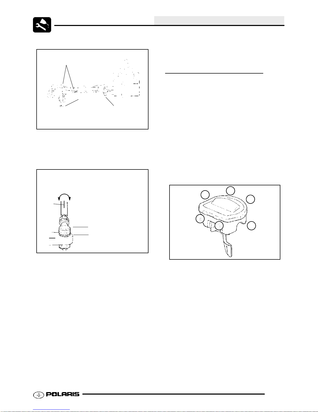
ETC Cover
Ill. 1
To remove the ETC cover:
1. Use a medium flat blade screwdriver and insert
blade into the pocket of the cover starting on the
#1 position.
2. Twist screwdriver slightlywhile liftingon the cover
to release snap.
3. Repeat procedure at the other five locations as
shown.
NOTE: Do not attempt to remove cover until all
latch points are released.
Removal Sequence
2.11
Page 31

MAINTENANCE
CHOKE (ENRICHER)
ADJUSTMENT
Boot
If the choke knob does not stay out when pulled,
adjust the choke tension by tightening (clockwise)the
jam nut under the rubber boot between the choke
knob and nut. Firmly grasp the rubber boot and
tighten until the choke slides freely but stays out when
pulled.
2100DX (PN 8712100DX) or the PET 2500 (PN
8712500).
4. Set idle speed to 1200 RPM. Always check
throttle cable freeplay after adjusting idle speed
and adjust if necessary.
5. Slowly turn mixture screw clockwise using the
pilot screw wrench until engine begins to miss.
6. Slowly turn mixture screw counterclockwise until
idle speed increases to maximum RPM.
Continue turning counterclockwise until idle RPM
begins to drop.
7. Center the pilot screw between thepoints in Step
5 and 6.
8. Re adjust idle speed if not within specification.
IDLE SPEED ADJUSTMENT
CV Carburetor
PILOT SCREW ADJUSTMENT
FRONT
(Engine)
Pilot Screw
1. Start engine and warm it up to operating
temperature (about 10 minutes).
lightly
2. Turn pilot screw in(clockwise) until
Turn screw out the specified number of turns.
NOTE: Do not tighten the pilot screw forcefully
againstthe seator the screw and/or seat willbe
permanently damaged.
Pilot Screw Adjustment:
Sportsman 400 -- 2 3/4 Turn Out
Sportsman 500 -- 2 Turns Out
seated.
Idle Screw
1. Start engine and warm it up thoroughly.
2. Adjust idle speed by turning the idle adjustment
screw in (clockwise) to increase or out
(counterclockwise) to decrease RPM. (Refer to
Ill. at right).
NOTE: Adjusting the idlespeed affects throttle cable
freeplay and electronic throttle control (ETC)
adjustment. Always check throttle cable freeplay
after adjusting idle speed and adjust if necessary.
Idle Speed:
1200 +/-- 200 RPM
3. Connect an accurate tachometer that will read in
increments of + or -- 50 RPM such as the PET
2.12
Page 32

MAINTENANCE
THROTTLE CABLE /
ELECTRONIC
CONTROL (ETC
THROTTLE
SWITCH)
ADJUSTMENT
1. Slide boot off throttle cable adjuster and jam nut.
2. Place shift selector in neutral and set parking
brake.
3. Start engine and set idle to specified RPM.
Boot
Ill. 1
NOTE: Be sure the engine is at operating
temperature. See Idle Speed Adjustment.
4. Loosen lock nut on in-line cable adjuster (Ill. 1).
5. Turn adjuster until 1/16 to 1/8 freeplay is
achieved at thumb lever. (Ill. 2). After making
adjustments, quickly actuate the thumb lever
several times and reverify freeplay.
Adjuster
Sleeve
Locknut
Boot
FUEL SYSTEM
WARNING
Gasoline is extremely flammable and explosive
under certain conditions.
S Alwaysstop the engine and refuel
outdoors or in a well ventilated
area.
S Do not smoke or allow open
flames or sparks in or near the
area where refueling is performed
or where gasoline is stored.
S Donot overfillthe tank. Donot fill
the tank neck.
S Ifyou get gasoline in youreyesor
if you swallow gasoline, seek
medical attention immediately.
S If you spill gasoline on your skin
or clothing, immediately wash it
off with soap and water and
change clothing.
S Never start the engine or let it run
in an enclosed area. Engine
exhaust fumesarepoisonousand
can result loss of consciousness
or death in a short time.
S Never drain the float bowl when
the engine is hot. Severe burns
may result.
FUEL LINES
Direction
of travel
Ill. 2
6. Tighten lock nut securely and slide boot
completely in place to ensure a water-tight seal.
7. Turn handlebars from left to right through the
entire turning range. If idle speed increases,
check for proper cable routing. If cable is routed
properly andin goodcondition, repeatadjustment
procedure.
1/16 - 1/8
Freeplay
Fuel Pump
Inspect
Fuel Lines
Filter
1. Check fuel lines for signs of wear, deterioration,
damage or leakage. Replace if necessary.
2. Besurefuel lines areroutedproperly and secured
with cable ties. CAUTION: Make sure lines are
not kinked or pinched.
3. Replace all fuel lines every two years.
2.13
Page 33

MAINTENANCE
VENT LINES
Check fuel tank, oil tank, carburetor, battery and
transmission vent lines for signs of wear,
deterioration, damage or leakage. Replace every two
years.
Be sure vent lines are routed properly and secured
with cable ties. CAUTION: Make sure lines are not
kinked or pinched.
FUEL FILTER
The fuel filter should be replaced in accordance with
the Periodic Maintenance Chart or whenever
sediment is visible in the filter.
Arrow Indicates Direction
of Flow
3. Turn drain screw out two turns and allow fuel in
the float bowl and fuel line to drain completely.
4. Inspect the drained fuel for water or sediment.
5. Tighten drain screw.
6. Turn fuel valve to “ON”.
7. Start machine and check for leaks.
NOTE: All tubes attached to the carburetor must be
check for pinching or blockage, as this will effect
engine performance.
Drain tube
attached
here
Ill. 1
Drain Screw
RES
To Carburetor
Ill. 2
1. Shut off fuel supply at fuel valve.
2. Remove line clamps at both ends of the filter.
3. Remove fuel lines from filter.
4. Install new filter and clamps onto fuel lines with
arrow pointed in direction of fuel flow.
5. Install clamps on fuel line.
6. Turn fuel valve “ON”.
7. Start engine and inspect for leaks.
CARBURETOR DRAINING
The carburetor float bowl should be drained
periodically to remove moisture or sediment from the
bowl, or before extended periods of storage.
NOTE: The bowl drain screw is locatedon the bottom
left side of the float bowl.
OFF
ON
Ill. 2
1. Turn fuel valve to the off position.
2. Place a clean container beneath the bowl drain
spigot or bowl drain hose.
2.14
Page 34

MAINTENANCE
COMPRESSION TEST
NOTE: 4-Stroke engines are equipped with an
automatic decompressor. Compression readingswill
vary in proportion to cranking speed during the test.
Average compression (measured) is about 50-90 psi
during a compression test.
Smooth idle generally indicates good compression.
Low engine compression is rarely a factor in running
condition problems above idle speed. Abnormally
high compression can be caused by a decompressor
malfunction, orworn or damaged exhaust camlobes.
Inspect camshaft and automatic decompression
mechanism if compression is abnormally high.
A cylinder leakage test is the best indication of engine
condition on models with automatic decompression.
Follow manufacturer’s instructions to perform a
cylinder leakage test. (Never use high pressure
leakage tester as crankshaft seals may dislodge and
leak).
Cylinder Compression
Standard 50-90 PSI
Cylinder Leakage
Service Limit 10 %
(Inspect for cause if leakage exceeds 10%)
BATTERY MAINTENANCE
WARNING
Battery electrolyteispoisonous. Itcontains
sulfuric acid. Serious burns can result from
contact with skin, eyes or clothing. Antidote:
External: Flush with water.
Internal: Drink large quantities of water or
milk. Follow with milkof magnesia, beaten
egg, or vegetable oil. Call physician immediately.
Eyes: Flush with water for 15 minutes and
get prompt medical attention.
Batteries produce explosive gases. Keep
sparks, flame, cigarettes, etc. away. Ventilate when charging or using in an enclosed
space. Always shield eyes when working
nearbatteries. KEEPOUT OF REACHOF
CHILDREN.
ENGINE MOUNTS
Inspect rubber engine mounts (A) for cracks or
damage. Check engine fasteners and ensure they
are tight.
A
A
A
NOTE: New Batteries:
charged beforeuse or batterylife willbe reduced
by10-30%of full potential. Charge battery for 3--5
hours at a current equivalent of 1/10 of the
battery’sratedamp/hourcapacity. Do not use the
alternator to charge a new battery.(Refer toBattery
Activation and Maintenance video PN 9917987)
The battery is located under the left rear fender.
Inspect the battery fluid level. When the electrolyte
nears the lower level, remove the battery and add
distilled water only to the upper level line. (Ill.1)
Maintain
between upper
and lower level
marks
Ill. 1
Batteries must be fully
2.15
Page 35

MAINTENANCE
To remove the battery:
1. Disconnect holder strap and remove cover.
2. Disconnect battery negative (-) (black) cable first,
followed by the positive (+) (red) cable.
CAUTION
To reduce the chance of sparks: Whenever
removing the battery, disconnect the negative
(black) cable first. When reinstalling the battery,
install the negative cable last.
3. Disconnect the vent hose.
4. Remove the battery.
5. Remove thefiller caps andadd
as needed to bring each cell to the proper level.
Do not overfill the battery. Fully recharge after
filling.
Use only distilled water. Tap water contains
minerals which are harmful to a battery.
Do not allow cleaning solution or tap water to
enter the battery, as it will shorten the life of the
battery.
6. Reinstall the battery caps.
7. Cleanbatterycablesandterminalswithastiffwire
brush. Corrosion can be removed using a
solution of one cup water and one tablespoon
baking soda. Rinse wellwith clean water and dry
thoroughly.
8. Reinstall battery,attachingpositive (+) (red)cable
first and then the negative (-) (black) cable.
9. Reattach vent hose making sure it is properly
routed and not kinked or pinched.
10. Coat terminals and bolt threads with Nyogelt
grease.
11. Reinstall battery cover and holder strap.
distilledwateronly
5. Measure gap with a wire gauge. Refer to
specifications forproperspark plug type and gap.
Adjust gap if necessary by bending the side
electrode carefully. (Ill. 1)
6. If necessary,replace spark plugwith proper type.
CAUTION: Severe engine damage may occur if
the incorrect spark plug is used.
7. Apply a small amount of anti-seize compound to
the spark plug threads.
8. Install spark plug and torque to specification.
Recommended Spark Plug:
Refer to Specifications
Spark Plug Torque:
14 Ft. Lbs. (19 Nm)
Spark Plug Gap
.036 (0.9 mm)
IGNITION TIMING
Refer to Chapter 10 for ignition timing procedures.
Ignition Timing 500 Engines:
302 BTDC@5000RPM
Engine-To-Frame Ground
Inspectengine-to-frame groundcable connection. Be
sure it is clean and tight.
SPARK PLUG
1. Remove spark plug hightension lead. Cleanplug
area so no dirt and debris can fall into engine
when plug is removed.
2. Remove spark plug.
3. Inspect electrodes for wear and carbon buildup.
Look for a sharp outer edge with no rounding or
erosion of the electrodes.
4. Clean with electrical contact cleaner or a glass
bead spark plugcleaner only. CAUTION: A wire
brush or coated abrasive should not be used.
2.16
Engine to Frame
Ground
Page 36

MAINTENANCE
LIQUID COOLING SYSTEM
OVER
Theenginecoolant levelis controlled or maintained
by the recovery system. The recovery system
components are the recovery bottle, radiator filler
neck, radiator pressure cap and connecting hose.
As coolant operating temperature increases, the
expanding(heated)excesscoolantisforcedoutofthe
radiatorpastthe pressurecap andintotherecovery
bottle. Asenginecoolanttemperaturedecreasesthe
contracting(cooled)coolantisdrawnbackupfromthe
tank past the pressure cap and into the radiator.
Somecoolant leveldroponnew machines isnormal
asthesystemispurgingitselfoftrappedair. Observe
coolant levels often during the break-in period.
Overheating of engine could occur if air is not fully
purged from system.
PolarisPremium60/40isalreadypremixedandready
to use. Do not dilute with water.
VIEW
COOLANT STRENGTH / TYPE
Test the strength of the coolant using an antifreeze
hydrometer.
COOLING SYSTEM HOSES
1. Inspect all hoses for cracks, deterioration,
abrasion or leaks. Replace if necessary.
2. Check tightness of all hose clamps.
CAUTION:
Do not over-tighten hose clamps at radiator, or
radiator fitting may distort, causing a restriction to
coolant flow. Radiatorhose clamp torque is36 in. lbs.
(4 Nm).
Antifreeze Hydrometer
S A 50/50 or 60/40 mixture of antifreeze
and distilled water will provide the
optimum cooling, corrosion protection,
and antifreeze protection.
S Do not use tap water, straight antifreeze,
orstraight water inthe system. Tapwater
contains minerals and impurities which
build up in the system.
S Straight water or antifreeze may cause
the system to freeze, corrode, or
overheat.
Polaris 60/40 Anti-Freeze / Coolant
(PN 2871323)
RADIATOR
A
B
1. Check radiator (A) air passagesfor restrictions or
damage. Check and clean the radiator screen
(B).
2. Carefully straighten any bent radiator fins.
3. Remove anyobstructions with compressed airor
low pressure water.
2.17
Page 37

MAINTENANCE
COOLING SYSTEM
PRESSURE
Refer to Page 3.5 for pressure test procedure.
TEST
COOLANT LEVEL
INSPECTION
The recovery bottle, located on the left side of the
machine,mustbemaintainedbetweentheminimum
andmaximumlevelsindicatedontherecoverybottle.
Recovery
Bottle
Accessible
Under Side
Panel
RADIATOR COOLANT LEVEL
INSPECTION
NOTE: This procedure is only required if the cooling
system has been drained for maintenance and/or
repair. However, if the recovery bottle has run dry, or
if overheating is evident, the level in the radiator
should be inspected and coolant added if necessary.
WARNING Never remove the pressure cap
when the engine is warm orhot. Escaping steam can
cause severe burns. The engine must be cool before
removing the pressure cap.
NOTE: Use of a non-standard pressure cap will not
allow the recovery system to function properly.
Front
Cover
With the engine at operatingtemperature, thecoolant
level should be between the upper and lower marks
on the coolant reservoir. If not:
1. Remove reservoir cap. Inner splash cap vent
hole must be clear and open.
2. Fill reservoir to upper mark with Polaris Premium
60/40 Anti Freeze / Coolant or 50/50 or 60/40
mixture of antifreeze and distilled water as
required for freeze protection in your area.
3. Reinstall cap.
NOTE: Ifoverheating is evident, allowsystem to cool
completely andcheck coolant level in the radiator and
inspect for signs of trapped air in system.
Rack
To access the radiator pressure cap:
Remove the four screws securing front rack. Turn
handlebars full left or right toprovide more clearance.
Remove front cover by placing your fingers under the
front of the cover and pulling upward.
AIR FILTER/PRE-FILTER
SER
It is recommended that the air filter and pre filter be
replaced annually. When riding in extremely dusty
conditions, replacement is required more often.
Thepre filter shouldbecleanedbefore eachride using
the following procedure:
1. Lift up on the rear of the seat.
VICE
2.18
Page 38

MAINTENANCE
2. Pull the seat back and free of the tabs. NOTE:
When reinstalling seat, make sure the slots in the
seat engage the tabs in the fuel tank.
3. Remove clips (6) from air box cover and remove
cover. Inspect thegasket. Itshould adhere tightly
to the cover and seal all the way around.
4. Loosen clamp and remove air filter
assembly.
Cover
Gasket
Pre-filter
Main Element
Ill.1
Cleaning:
NOTE: Apply a small amount of general purpose
grease to the sealing edges of the filter before
reinstalling.
Filter Clamp
Ill.2
Proper Filter Placement
Main Filter
5. Slip the pre-filter element off of main element.
Clean the pre filter with high flash point solvent,
followed by hot soapy water.
6. Rinse and dry thoroughly.
7. Inspect element for tears or damage.
8. Apply foam filter oil or clean engine oil and
squeeze until excess oil is removed.
9. Inspect main filterand replaceif necessary. Ifthe
filter has been soaked with fuel or oil it must be
replaced.
Installation:
10. Reinstall pre-filter element over main filter. Be
sure the element covers entire surface of main
filter without folds, creases, or gaps.
11. Reinstall filter on main filter mount. Place filter
clamp over the assembly and tighten.
Filter Support
Air Box
Ill.3
NOTE: The air filter should rest on the filter support.
Proper placement of the air filter is important to
prevent rattles and air leaks. See Illustration above.
12. Install air box cover and secure with clips.
Front
AIR BOX SEDIMENT TUBE
Periodically check the air box drain tube located
toward the rear of the machine. Drain whenever
deposits are visible in the clear tube.
1. Remove drain plug from end of sediment tube.
2. Drain tube.
2.19
Page 39

MAINTENANCE
3. Reinstall drain plug.
Sediment Tube
Ill.1
NOTE: The sediment tube will require morefrequent
service if the vehicle is operated in wet conditions or
at high throttle openings for extended periods.
BREATHER FILTER
INSPECTION
Four cycle ATV engines are equippedwith a breather
filter. Thein-line filter is similar in appearance to afuel
filter, and is visible on the left side (Location A).
In-line breather filters should be installed with the
arrow pointing toward the engine (away from the air
box).
Typical Breather Filter Location
In-Line Breather Filter
Location A
NOTE: In-line breather filter service life is extended
when the foam air box pre-filter is in place and
maintained properly. Never operate the engine
without the pre-filter.
BREATHER HOSE
1. Be sure breather line is routed properly and
securedin place. CAUTION: Makesurelines are
not kinked or pinched.
RECOIL HOUSING
Crankcase Drain
Recoil Drain
S Drain the housing periodically to remove
moisture.
S Drain the recoil housing after operating
the ATV in very wet conditions. This
should also be done before storing the
ATV. The drain screw is located at the
bottom of therecoil housing. Remove the
screw with a 10 mm wrench. Reinstall
screw once housing has been drained.
S CAUTION: Make sure the manual start
handle is fully seated on the recoil
housing, especially when travelling in wet
areas. If it is not sealed properly, water
may enter the recoil housing and damage
components.
S Water will enter the recoil housing if the
starter handleis disengagedfromtherope
guide when under water.
S After travelling in wet areas the recoil
housing and starter should always be
drained completely by removing the
recoil.
S Do not open the crankcase drain unless
the engine has ingested water. Some
engine oil will be lost if crankcase drain is
opened.
S If recoil handle seal has been damaged,
the handle shopuld be replaced.
2.20
Page 40

MAINTENANCE
ENGINE OIL LEVEL
A
The oil tank is located on the left side of the vehicle.
To check the oil level:
1. Set machine on a level surface.
2. Start and run engine for 20-30 seconds. This will
return oil to its true level in the oil tank.
3. Stop engine, remove dipstick (A) and wipe dry
with a clean cloth.
4. Reinstall dipstick, screw the dipstick into place.
OIL AND FILTER CHANGE
WARNING
Personal injury can occur when handling used oil. Hot oil can cause burns
or skin damage.
NOTICE:
Care must be taken to ensure that fluids are
contained. Be prepared to collect the fluid
with suitable containers before opening any
compartment or disassembly any component
containing fluids.
1. Place vehicle on a level surface.
2. Run enginetwotothreeminutes until warm. Stop
engine.
3. Clean area around drain plug (B) at bottom of oil
tank.
4. Place a drain pan beneath oil tank and remove
drain plug. CAUTION: Oil may be hot. Do not
allow hot oil to come into contact with skin as
serious burns may result.
NOTE: The dipstick must be screwed completely in
to ensure accurate measurement.
ADD 8 OZ. NORMAL FULL
Maintain Oil Level In Normal Range
Screw Dipstick in completely to check
5. Remove dipstick and check to see that the oil
level is in the normal range. The oil should be
between the top line and the bottom line on the
dipstick. Add oil as indicated by the level on the
dipstick. Do not overfill.
NOTE: Rising oil level between checks in cool
weatherdriving,can indicatemoisturecollectinginthe
oil reservoir. If the oil level is over the full mark,
change the oil.
D
A
B
5. Allow oil to drain completely.
6. Replacesealingwasher (A)on drainplug. NOTE:
The sealing surfaces on drain plug and oil tank
should be clean and free of burrs, nicks or
scratches.
7. Reinstall drain plug and torque to 14 ft. lbs. (19
Nm).
8. Loosen clamp (D).
9. Remove oil hose fromscreenfitting (C) onbottom
of oil tank.
10. Remove screen fitting (C) and clean the screen.
11. Apply Loctitet Thread Sealant 565 (PN
2871956) or an equivalent pipe thread sealant or
PTFE sealant tape to clean, oil free threads of
fitting.
C
2.21
Page 41

MAINTENANCE
12. Install fitting and torque to 14-17 ft.lbs. (19--23
Nm).
13. Installoil hoseonfitting andtighten clamp to 25in.
lbs. (3 Nm).
E
14. Place shop towels beneath oil filter (E) . Use Oil
Filter Wrench (PV--43527), turn filter
counterclockwise to remove.
15. Usingaclean drycloth,clean filter sealingsurface
on crankcase.
16. Lubricate O-ring on newfilter with a film of engine
oil. Check to make sure the O-ring is in good
condition.
17. Install newfilter andturnby handuntilfiltergasket
contacts the sealing surface, then turn and
additional 1/2 turn.
21. Place gear selector in neutral and set parking
brake.
NOTE: Clampor pinch off the vent line2” from the oil
tankas shown below in the Oil Pump Priming
Procedure for the 500 engine.
22. Re-check the oil level on the dipstick and add oil
as necessary to bring the level to the upper mark
on the dipstick.
23. Dispose of used filter and oil properly.
Oil Tank Drain Plug Torque:
14 ft. lbs. (19 Nm)
Crankcase Drain Plug Torque:
14 ft. lbs. (19 Nm)
Oil Filter Torque:
Turn by hand until filter gasket
contacts sealing surface, then
turn an additional 1/2 turn
Oil Filter Wrench:
(PV--43527)
Oil Tank Screen Fitting Torque:
14-17 ft. lbs. (19 Nm --23 Nm)
Recommended Engine Oil:
Polaris Premium 4 All Season
Synthetic, 0W--40, (PN 2871281)
Crankcase Drain
Engine Sump Drain Plug - Bottom View
18. Approximately 1 cup of engine oil will remain in
thecrankcase. Todrain, removedrain plugfound
on lower right side of crankcase.
NOTE: The sealing surfaces on the drain plug and
crankcase should be clean andfree of burrs, nicks or
scratches.
19. Reinstall drain plug.
20. Remove dipstick andfill tank with 2 quarts (1.9 L)
ofPolarisPremium 4Synthetic Oil (PN 2871844).
Ambient Temperature Range:
-40 F to 120 F
OIL PUMP PRIMING
PROCEDURE
NOTE: This priming procedure must be
performed whenever the oil hose connection
between the oil tank and pump inlet has been
disconnected.
Approx.
Oil Tank
(500)
To Air Box
2I
Slit
Pinch Off
Vent Hose
2.22
Page 42

MAINTENANCE
1. Clamp or pinch off vent line approximately 2I
fromoil tanktoavoid theend ofoil tankvent fitting,
and the vent line’s pressure relief slit
2. Run engine for 45-60 seconds.
3. Remove the vent line clamp. The oil pump will
now be properly primed and ready for field
operation.
VALVE CLEARANCE
Inspect and adjust valve clearance while the engine
is cold and the piston positioned at Top Dead Center
(TDC) on compression stroke.
1. Remove the seat.
2. Remove body panels and fuel tank as necessary
to gain access to valve cover.
3. Remove the spark plug high tension lead and
remove thesparkplug. CAUTION: Placeaclean
shop towel into the spark plug cavity to prevent
dirt from entering.
4. Remove rocker cover bolts, cover and gasket.
NOTE: It may be necessary to tap cover lightly
with a soft-faced hammer to loosen it from the
cylinder head.
5. Remove timing inspection plug from recoil
housing.
CAUTION: Failure to position the crankshaft at TDC
on compression stroke will result in improper valve
adjustment.
Sprocket alignment pin facing up
6. Rotate engine slowly with recoil rope, watching
the intake valve(s) open and close.
NOTE: At this point watch the camshaft sprocket
locating pin and slowly rotate engine until locating pin
is facing upward, directly inline with the crankshaft to
camshaft center line as shown. The camshaft lobes
should be pointing downward.
7. Verify accurate TDC positioning by observing the
“T” mark aligned with the pointer in the timing
inspection hole. In this position there should be
clearance on all valves.
INTAKE VALVE CLEARANCE
ADJUSTMENT
1. Insert a.006 (.15mm) feelergauge betweenend
of intake valve stem and clearance adjuster
screw.
2. Using a 10 mm wrench and a screwdriver, loosen
adjuster lock nut and turn adjusting screw until
there is a slight drag on the feeler gauge.
3. Hold adjuster screw and tighten adjuster lock nut
securely.
4. Re-check the valve clearance.
5. Repeat adjustment procedure if necessary until
clearance is correct with locknut secured.
6. Repeat this step for the other intake valve.
Crankshaft-to-Camshaft Centerline
INTAKE VALVE CLEARANCE
.006 (.15 mm)
2.23
Page 43

MAINTENANCE
EXHAUST VALVE
CLEARANCE
Feeler Gauge for Both Valves
NOTE: The exhaust valves share a common rocker
arm, and must be adjusted using two feeler gauges.
1. Insert .006 feeler gauge(s) between end of
exhaust valve stem and adjuster screw(s).
2. Loosen locknut(s)and turnadjusterscrew(s) until
there is a slight drag on feeler gauge(s). The
Valve/Clutch Adjuster Tool (PA--44689) can be
used to adjust the 500 engines valves. NOTE:
Both feeler gauges should remain insertedduring
adjustment of each valve.
ADJUSTMENT
500 Engine
components are replaced, checkfront end alignment.
Use only genuine Polaris parts.
WARNING
Dueto the criticalnatureofthe procedures outlined in this chapter, Polaris recommends
steering component repair and adjustment be
performedbyanauthorizedPolarisMSD--certified technician when replacing worn or damaged steering parts. Use only genuine Polaris
replacement parts.
One of two methods can be used to measure toe
alignment. The string method andthe chalk method.
If adjustment is required, refer to following pages for
procedure.
TIE ROD END / STEERING
INSPECTION
S To check for play in the tie rod end,
grasp the steering tie rod, pull in all
directions feeling for movement.
S Repeat inspection for inner tie rod
end on steering post.
EXHAUST VALVE CLEARANCE
.006 (.15 mm)
3. When clearance is correct, hold adjuster screw
and tighten locknut securely
4. Re-check the valve clearance.
5. Repeat adjustment procedure if necessary until
clearance is correct with locknut secured.
STEERING
The steering components should be checked
periodicallyfor loose fasteners,worn tie rod ends,and
damage. Also check to make sure all cotter pins are
in place. If cotter pins areremoved, they must not be
re-used. Always use new cotter pins.
Replace any worn or damaged steering components.
Steering should move freely through entire range of
travel without binding. Check routing of all cables,
hoses, and wiring to be sure the steering mechanism
isnot restrictedorlimited. NOTE: Wheneversteering
S Replace any worn steering
components. Steering should move
freely through entire range of travel
without binding.
S Elevate front end of machine so front
wheels are off the ground. Check for
any looseness in front hub / wheel
assembly by grasping the tire firmly
at top and bottom first, and then at
front andrear. Try to move the wheel
and hub by pushing inward and
pulling outward.
2.24
Page 44

MAINTENANCE
TIE ROD END/STEERING INSPECTION
CONT’D
S If abnormal movement is detected,
inspect the hub and wheel assembly
to determine the cause ( possible
loose wheel nuts or loose front hub
components).
Check for Loose Wheel or Hub
S Refer to the Body/Steering Chapter
5 or Final Drive Chapter7 for service
procedures.
CAMBER AND CASTER
The camber and caster are non-adjustable.
WHEEL ALIGNMENT
METHOD 1:
STRAIGHTEDGE OR STRING
Be sure to keep handlebars centered. See notes
below.
NOTE: String should just touch side surface of rear tire on each side of machine.
Measure
from string
to rim at
front and
rear of rim.
Rear rim
measure-
ment should
be 1/16 to
1/8 (.2 to .3
cm) more
than front rim
measure-
ment.
NOTE: The steering post arm “frog” can be
used as an indicator of whether the handle-
bars are straight. The frog should always
point straight back from the steering post.
WHEEL ALIGNMENT
METHOD 2:
1. Place machine on a smooth level surface.
2. Set handlebars in a straight ahead position and
secure handlebars in this position. NOTE: The
steering arm “frog” can be used as an indicator of
whether the handlebars are straight. The frog
CHALK
2.25
Page 45

MAINTENANCE
should always point straight back from the
steering post.
3. Place a chalk mark on the center line of the front
tires approximately 10 (25.4 cm) from the floor or
as close to the hub/axle center line as possible.
NOTE: It is important that the height of both
marks be equally positioned in order to get an
accurate measurement.
4. Measure the distance between the marks and
record the measurement. Call this measurement
“A”.
5. Rotate thetires 180 by movingvehicleforwardor
backward. Position chalkmarks facingrearward,
even with the hub/axle centerline.
6. Again measure the distance between the marks
and record. Call this measurement “B”. Subtract
measurement “B” from measurement “A”. The
difference between measurements “A” and “B” is
the vehicle toe alignment. The recommended
vehicle toe tolerance is 1/8 to 1/4 (.3 to .6 cm)
toeout. Thismeans the measurement at thefront
ofthe tire (A) is1/8 to1/4 (.3to .6 cm) widerthan
the measurement at the rear (B)
TOE ALIGNMENT
ADJUSTMENT
If toe alignment is incorrect, measure the distance
between vehicle center and each wheel. This will tell
you which tie rod needs adjusting. NOTE: Be sure
handlebars are straight ahead before determining
which tie rod(s) need adjustment.
Hold
Rod End
Incorrectly
Tightened
Jam Nut
Ill.2
Correctly
Tightened
Jam Nut
Ill.2
To adjust toe alignment:
S Hold tie rod end to keep it from rotating.
S Loosenjamnuts atbothendofthe tierod.
S Shorten or lengthen the tie rod until
alignmentisas required to achieve the
proper toe setting as specified in
Method 1 or Method 2.
S IMPORTANT: When tightening the tie
rod end jam nuts, the rod ends must be
held parallel to prevent rod end damage
and premature wear. Damage may not
be immediately apparent if done
incorrectly. See illustration 2.
S After alignment is complete, torque jam
nuts to 12-14 ft. lbs. (16-19 Nm).
FRONT HUB FLUID LEVEL
CAUTION: During tie rod adjustment, it is very
important that the following precautions be taken
when tightening tie rod end jam nuts. If the rod end
is positioned incorrectly it will not pivot, and may
break.
2.26
INSPECTION
Page 46

MAINTENANCE
To check front hub fluid: (See next page)
1. Place vehicle on a level surface.
2. Turnwheeluntilfront hubfill/check plugisin either
the 4 o’clock or 8 o’clock position.
3. Remove fill/check plug.
4. Add Polaris Demand Drive HubFluidifnecessary
until fluid trickles out. NOTE: Do not force the
fluid into the hub under pressure or seal damage
may occur.
5. Reinstall plug.
6. Repeat procedure for other hub.
FRONT HUB FLUID CHANGE
EXHAUST PIPE
WARNING
S Do not perform clean out immediately
after the engine has been run, as the exhaust system becomes very hot. Serious
burns could result from contact with exhaust components.
S To reduce fire hazard, make sure that
there are no combustible materials in the
area when purging the spark arrestor.
S Wear eye protection.
S Do not stand behind or in front of the ve-
hicle while purging the carbon from the
spark arrestor.
S Never run the engine in an enclosed
area. Exhaust contains poisonous carbon monoxide gas.
S Do not go under the machine while it is
inclined. Set the hand brake and block
the wheels to prevent roll back.
1. Place a drain pan beneath the hub.
2. Remove check/fill plug.
3. Turnthe hubto the6 o’clock positionand drain the
fluid
into the drain pan.
4. Turnwheeluntilfront hubfill/check plugisin either
the 4 or 8 o’clock position.
5. Add Polaris Demand Drive Hub Fluid (PN
2871654) until fluid trickles out. NOTE: Do not
force the fluid into the hub underpressure or seal
damage may occur.
Polaris Demand Drive Hub Fluid:
(PN 2871654) - 8 oz.
(PN 2872277) - 2.5 gallon
Failure to heed these warnings could result in
serious personal injury or death.
The exhaust pipe must be periodically purged of
accumulated carbon as follows:
1. Remove the clean out plugs located on the
bottom of the muffler as shown in illustration 1.
Ill.1
2. Place the transmission in neutral and start the
engine. Purge accumulated carbon from the
system by momentarily revving the engine
several times.
3. If some carbon is expelled, cover the exhaust
outlet and rap on the pipe around the clean out
plugs while revving the engine several more
times.
4. If particles arestill suspected to be in the muffler,
backthe machineontoanincline so therear of the
machine is one foot higherthan the front. Set the
hand brake andblock the wheels. Make sure the
Clean Out Plug
2.27
Page 47

MAINTENANCE
machine is in neutral and repeat Steps 2 and 3.
SEE WARNING
5. If particles arestill suspected to be in the muffler,
drive the machine onto the incline so the front of
the machine is one foot higher than the rear. Set
the hand brakeand block the wheels. Make sure
the machine is in neutral and repeat Steps 2 and
3. SEE WARNING
6. Repeat steps 2 through 5 until no more particles
are expelled when the engine is revved.
7. Stop the engine and allow the arrestor to cool.
8. Reinstall the clean out plugs.
BRAKE SYSTEM INSPECTION
The following checks are recommended to keep the
brakesystem ingood operatingcondition. Servicelife
of brake system components depends on operating
conditions. Inspect brakes in accordance with the
maintenance schedule and before each ride.
S Keepfluidlevel inthemastercylinder
reservoir to the indicated level inside
reservoir.
S Use Polaris DOT 3 Brake Fluid (PN
2870990).
Sight
Glass
Parking Brake
Lock
BRAKE PAD INSPECTION
Pads should be changed when the friction material is
wornto 3/64 (.1cm),or aboutthethicknessof adime.
3/64
(.1cm)
Minimum
Thickness
HOSE/FITTING INSPECTION
Check brake system hoses and fittings for cracks,
deterioration, abrasion, and leaks. Tighten any loose
fittings and replace any worn or damaged parts.
AUXILIARY BRAKE TESTING
The auxiliary brake should be checked for proper
function.
Rear Master Cylinder Reservoir
Max
Min
S Check brake system for fluid leaks.
S Check brake for excessive travel or
spongy feel.
S Check friction pads for wear,
damage or looseness.
S Check surface condition of the disc.
Auxiliary Foot Brake Pedal
Full Height
Floor
Board Surface
1. Support the rear wheels off the ground.
2. While turning the rear wheels by hand, apply the
auxiliary foot brake. This brake should not stop
the wheels from turning until the lever is half way
between its rest position and bottoming on the
footrest.
Full
Engagement
2.28
Page 48

MAINTENANCE
AUXILIARY BRAKE
ADJUSTMENT
Use the following procedure to inspect the hydraulic
auxiliary (foot) brake system and adjust or bleed if
necessary:
First, check footbrakeeffectivenessby applying50lb.
(approx.) downwardforceon the pedal. Thetopof the
pedal should be at least 1 inch, (25.4mm) above the
surface of the footrest.
(HYDRAULIC)
Auxiliary Brake
SUSPENSION SPRING
PRELOAD
Center Spring
Adjustment Ring
Operator weight and vehicle loading affect
suspensionspringpreloadrequirements.Adjustas
necessary.
ADJUSTMENT
FRONT SUSPENSION
Compress and release front suspension. Damping
should be smooth throughout the range of travel.
Check all front suspension components for wear or
damage.
Inspect front strut cartridges for leakage.
1/8, to 1/4,
Free Play
50 lbs
If less than one inch, two things must be examined:
Free Play:
Free play of the brake pedal should be 1/8 - 1/4
inch (3.2 - 6.35 mm).
If free play is excessive, inspect pedal, linkage, and
master cylinder for wear or damage and replace any
parts as needed.
Bleeding:
If free play is correct and brake pedal travel is still
excessive, air may be trapped somewhere in the
system. Bleedthe hydraulic auxiliary brake system in
a conventional manner, following the procedure
outlined in Brake Chapter 9.
1 or greater
Floorboard
CONTROLS
Check controls for proper operation, positioning
andadjustment.
Brake control and switch must be positioned to allow
brake lever to travel throughout entire range without
contacting switch body.
2.29
Page 49

MAINTENANCE
Align clamp
edge with
knurl
Throttle
assembly
clamp
WHEEL, HUB, AND SPINDLE
TORQUE T
Item Specification
Front Wheel Nuts 20 Ft. Lbs. (27 Nm)
Rear Wheel Nuts 20 Ft. Lbs. (27 Nm)
Front Spindle Nut Refer to procedure listed in
Rear Hub Retaining Nut 100 Ft. Lbs. (136 Nm)
ABLE
Chapter 7
WHEEL REMOVAL FRONT OR
Align throttle control assembly clamp with knurl on
handlebar
WHEELS
Inspect allwheelsforrunoutor damage. Checkwheel
nuts andensure they aretight. Donotover tightenthe
wheel nuts.
WARNING
Operating an ATVwith worntireswill increase
thepossibility of the vehicle skidding and possible loss of control.
Worn tires can cause an accident.
Always replace tires when the tread depth
measures 1/8 (.3 cm) or less.
WHEELS
Inspect allwheelsforrunoutor damage. Checkwheel
nuts andensure they aretight. Donotover tightenthe
wheel nuts.
REAR
Flange Nuts:
Flat side against wheel
1. Stop the engine, place the transmission in gear
and lock the parking brake.
2. Loosen the wheel nuts slightly.
3. Elevate the side of the vehicle by placing a
suitable stand under the footrest frame.
4. Remove the wheel nuts and remove the wheel.
WHEEL INSTALLATION
1. With the transmission in gear and the parking
brake locked, place the wheel in the correct
positionon the wheelhub. Besurethevalvestem
is toward the outside and rotation arrows on the
tire point toward forward rotation.
2. Attach the wheel nuts and finger tighten them.
3. Lower the vehicle to the ground.
4. Securely tighten the wheel nuts to the proper
torque listed in the table above.
2.30
CAUTION:
Page 50

MAINTENANCE
If wheels are improperly installed it could affect
vehicle handling and tire wear. On vehicles with
taperedrear wheelnuts, make suretaperedendof nut
goes into taper on wheel.
TIRE PRESSURE
CAUTION:
Maintain proper tire pressure. Refer to the warning
tire pressure decal applied to the vehicle.
Tire Pressure Inspection (PSI - Cold)
Front Rear
5 5
TIRE INSPECTION
S Impropertireinflation mayaffectATV
maneuverability.
S When replacing a tire always use
original equipment size and type.
S Theuse of non-standard size or type
tires may affect ATV handling.
FRAME, NUTS, BOLTS,
ASTENERS
F
Periodically inspect the torque of all fasteners in
accordance with the maintenance schedule. Check
that all cotter pins are in place. Refer to specific
fastener torques listed in each chapter.
Tire Tread Depth
Always replace tires whentread depth is worn to
1/8 (3 mm) or less.
Tread
Depth 1/8I (3 mm)
WARNING
Operating anATVwith worn tires will increase the possibility ofthe vehicleskidding easily with possible loss of control.
Worn tires can cause an accident.
Always replace tires when the tread
depth measures 1/8 (.3 cm) or less.
2.31
Page 51

MAINTENANCE
NOTES
2.32
Page 52

CHAPTER 3
ENGINE
Torque Specifications 3.2........................
Special Tools 3.2...............................
EH50PL Service Data . . 3.3-3.4......................
Torque Patterns 3.5.............................
Piston Identification 3.5..........................
Cooling System Pressure Test 3.6--3.7................
Cooling System Specifications 3.7................
Engine Removal 3.7............................
Engine Installation Notes 3.8.....................
Cylinder Honing 3.8--3.9.............................
Crankshaft Runout Inspection 3.9--3.10.................
EH50PL Engine Lubrication 3.10..................
EH50PL Oil Pump Priming Procedure 3.10..........
EH50PL Lubrication/Oil Flow 3.11-3.12.................
EH50PL Engine Exploded View 3.13...............
EH50PL Engine Top End Disassembly 3.14-3.23.........
EH50PL Valve Seat Service 3.23-3.26..................
EH50PL Cylinder Head Assembly 3.26-3.31.............
EH50PL Engine Bottom End Disassembly 3.31-3.36......
EH50PL Crankcase & Bearing Assembly 3.37--3.38.......
EH50PL Crankshaft End Play Inspection 3.38-3.39.......
EH50PL Counter Balancer End Play Inspection. 3.40.
EH50PL Oil Pump Shaft End Play Inspection 3.40--3.41...
EH50PL Engine Assembly/Inspection 3.41-3.51..........
Sealed Recoil Disassembly/Inspection 3.51--3.52.........
Sealed Recoil Assembly 3.52.....................
Spark Plug Fouling Checklist 3.53.................
Troubleshooting 3.53--3.54.............................
ENGINE
3
3.1
Page 53

ENGINE
TORQUE SPECIFICATIONS
TORQUE SPECIFICATIONS
Fastener Size EH42PLE/
EH50PLE
Ft. Lbs. (Nm)
Blind Plug (Oil
Pressure)
Camshaft Sprocket 6mm 5-6.5 (7-9 Nm)
Camshaft Chain
Tensioner Lever
Camshaft Chain
Tensioner
Camshaft Chain
Tensioner Cap
Carburetor Adaptor 8mm 12-14 (16-20 Nm)
Crankcase 8mm 14-15 (19-21 Nm)
Crankshaft Slotted
Nut (Cam Chain
Drive Sprocket)
Cylinder Base
Bolts
Cylinder Head
Bolts
Drive Clutch Bolt 7/16 -
Flywheel 16mm 58-72 (78-98 Nm)
Oil Delivery Pipe 12mm 11-15 (15-21 Nm)
Oil Drain Bolt
(Crankcase)
Oil Filter Pipe Fit-
ting
Oil Hose Fitting 1/8 Pipe
Oil Pump 6mm 5-6.5 (7-9 Nm)
Oil Pump Case
Screw
One Way Valve 11mm 14-19 (20-25 Nm)
Recoil Housing 6mm 5-6.5 (7-9 Nm)
Rocker Cover 6mm 7-8 (9-11 Nm)
Rocker Support 8mm 8-10 (11-13 Nm)
Rocker Adjuster
Screw
Water Pump Impel-
ler Nut
1/8 PT
6.5-11 (9-15 Nm)
(28tpi)
6mm 5-6.5 (7-9 Nm)
6mm 5-6.5 (7-9 Nm)
11mm 14-19 (20-25 Nm)
28mm 35-51 (47-69 Nm)
10mm
6mm
11mm
6mm
45-49 (61-67 Nm)
6-8 (9-11 Nm)
Refer to Engine
Assembly for
torque procedure
40 (55 Nm)
20
14mm 14-17 (19-23 Nm)
20mm 36-43 (49-59 Nm)
6.5-11 (9-15 Nm)
Thread
5mm 1.5-2 (2-3 Nm)
6mm 6-7 (8-10 Nm)
6mm 5-6.5 (7-9 Nm)
Water Pump
6mm 5-6.5 (7-9 Nm)
Housing Cover
Stator Plate 6mm 5-6.5 (7-9 Nm)
Starter Motor 6mm 5-6.5 (7-9 Nm)
Spark Plug 14mm 9-11 (12-15 Nm)
SPECIAL TOOLS
PART NUMBER TOOL
DESCRIPTION
2200634 Valve Seat
2870390 Piston Support
2871043 Flywheel Puller
2871283 Crankshaft/Water
5131135 Water Pump
2870569 Crankshaft Truing
2870975 Mity Vact
PV--43527 OIl Filter Wrench
ReconditioningKit
Block
Pump Seal Install
Kit
Install Kit
Stand
Pressure TestTool
3.2
Page 54

ENGINE SERVICE DATA
g
j
j
y
g
g
g
g
g
Cylinder Head / Valve EH42PLE EH50PLE
Rocker Arm
Camshaft Cam lobe height In
Cylinder Head
Valve Seat Contacting width In
Valve Guide
Valve Margin thickness In
Valve
Valve Spring Overall length
Rocker arm ID .8669-.8678² (22.020-22.041 mm) .8669-.8678² (22.020-22.041 mm)
Rocker shaft OD .8656-.8661² (21.987-22.0 mm) .8656-.8661² (21.987-22.0 mm)
Rocker shaft Oil Clearance
Camshaft journal OD
Camshaft journal bore ID
Camshaft Oil clearance
Surface warpage limit .0020² (.05 mm) .0020² (.05 mm)
Standard height 3.870² (98.3 mm) 3.870² (98.3 mm)
Inner diameter .2362-.2367² (6.0-6.012 mm) .2362-.2367² (6.0-6.012 mm)
Protrusion above head .689-.709² (17.5-18.0 mm) .689-.709² (17.5-18.0 mm)
Stem diameter In .2343-.2348² (5.950-5.965 mm) .2343-.2348² (5.950-5.965 mm)
Stem oil clearance Std
Overall length
Squareness .075² (1.9 mm) .075² (1.9 mm)
Std .0008-.0021² (.020-.054 mm) .0008-.0021² (.020-.054 mm)
Limit .0039² (.10 mm) .0039² (.10 mm)
Std 1.2884-1.2924² (32.726-32.826 mm) 1.2884-1.2924² (32.726-32.826 mm)
Limit 1.2766² (32.426 mm) 1.2766² (32.426 mm)
Ex
Std 1.2884-1.2924² (32.726-32.826 mm) 1.2884-1.2924² (32.726-32.826 mm)
Limit 1.2766² (32.426 mm) 1.2766² (32.426 mm)
Mag 1.4935-1.4941² (37.935-37.950 mm) 1.4935-1.4941² (37.935-37.950 mm)
PTO 1.4935-1.4941² (37.935-37.950 mm) 1.4935-1.4941² (37.935-37.950 mm)
Mag 1.4963-1.4970² (38.005-38.025 mm) 1.4963-1.4970² (38.005-38.025 mm)
PTO 1.4963-1.4970² (38.005-38.025 mm) 1.4963-1.4970² (38.005-38.025 mm)
Std .0022-.0035² (.055-.090 mm) .0022-.0035² (.055-.090 mm)
Limit .0039² (.10 mm) .0039² (.10 mm)
Std .028² (.7 mm) .028² (.7 mm)
Limit .055² (1.4 mm) .055² (1.4 mm)
Ex
Std .039² (1.0 mm) .039² (1.0 mm)
Limit .071² (1.8 mm) .071² (1.8 mm)
Std .039² (1.0 mm) .039² (1.0 mm)
Limit .031² (.8 mm) .031² (.8 mm)
Ex
Std .047² (1.2 mm) .047² (1.2 mm)
Limit .031² (.8 mm) .031² (.8 mm)
Ex .2341-.2346² (5.945-5.960 mm) .2341-.2346² (5.945-5.960 mm)
In .0014-.0024² (.035-.062 mm) .0014-.0024² (.035-.062 mm)
Ex .0016-.0026² (.040-.067 mm) .0016-.0026² (.040-.067 mm)
Limit .0059² (.15 mm) .0059² (.15 mm)
In 3.976² (101.0 mm) 3.976² (101.0 mm)
Ex 3.984² (101.2 mm) 3.984² (101.2 mm)
Std 1.654² (42.0 mm) 1.654² (42.0 mm)
Limit 1.575² (40.0 mm) 1.575² (40.0 mm)
ENGINE
3.3
Page 55

ENGINE
y
ggg
g
g
g
g
g
g
g
g
g
g
ENGINE SERVICE DATA
Cylinder / Piston / Connecting Rod EH42PLE EH50PLE
Cylinder
Piston Outer diameter
Piston Pin
Piston Ring Piston ring installed gap Top ring
Piston Ring Standard clearance -
Connecting
Rod
Crankshaft Crankshaft runout limit .0024² (.06 mm) .0024² (.06 mm)
KEY- Std: Standard;OS: Oversize;ID: InnerDiameter;
OD: OuterDiameter; Mag: MagnetoSide; PTO: Power
Take Off Side
Surface warpage limit (mating with cylinder head) .0020² (.05 mm) .0020² (.05 mm)
Cylinder bore Std 3.4606-3.614² (87.900-87.920 mm) 3.6221-3.6228² (92.00-92.02 mm)
Taper limit .0020² (.050 mm) .0020² (.050 mm)
Out of round limit .0020² (.050 mm) .0020² (.050 mm)
Piston clearance
Boring limit .020² (.5 mm) .020² (.5 mm)
Std 3.4596-3.4600² (87.875-87.885 mm) 3.6204-3.6215² (91.970-91.985 mm)
.0098² (.25 mm) OS 3.4695-3.4699² (88.125-88.135 mm) 3.6304-3.6310² (92.21-92.23 mm)
.0197² (.50 mm) OS 3.4793-3.4797² (88.375-88.385 mm) 3.6403-3.6407² (92.46-92.47 mm)
Standard inner diameter of piston pin bore .9055-.9057² (23.0-23.006 mm) .9055-.9057² (23.0-23.006 mm)
Outer diameter .9053-.9055² (22.994-23.0 mm) .9053-.9055² (22.994-23.0 mm)
Standard clearance-piston pin to pin bore .0002-.0003² (.004-.008 mm) .0002-.0003² (.004-.008 mm)
Degree of fit Piston pin must be a push (by hand) fit at 68° F (20° C)
Second
ring
Oil ring
Top ring
piston ring to ring groove
Second
ring
Connecting rod small end ID .9058-.9063² (23.007-23.020 mm) .9058-.9063² (23.007-23.020 mm)
Connecting rod small end radial clearance
Connecting rod big end side clearance
Connecting rod big end radial clearance
Std .0006-.0018² (.015-.045 mm) .0006-.0018² (.015-.045 mm)
Limit .0024² (.060 mm) .0024² (.060 mm)
Std .0079-.0138² (.20-.36 mm) .0079-.0138² (.20-.36 mm)
Limit .039² (1.0 mm) .039² (1.0 mm)
Std .0079-.0138² (.20-.36 mm) .0079-.0138² (.20-.36 mm)
Limit .039² (1.0 mm) .039² (1.0 mm)
Std .0079-.0276² (.20-.70 mm) .0079-.0276² (.20-.70 mm)
Limit .059² (1.5 mm) .059² (1.5 mm)
Std .0016-.0031² (.040-.080 mm) .0016-.0031² (.040-.080 mm)
Limit .0059² (.15 mm) .0059² (.15 mm)
Std .0012-.0028² (.030-.070 mm) .0012-.0028² (.030-.070 mm)
Limit .0059² (.15 mm) .0059² (.15 mm)
Std .0003-.0010² (.007-.026 mm) .0003-.0010² (.007-.026 mm)
Limit .0020² (.05 mm) .0020² (.05 mm)
Std .0039-.0256² (.1-.65 mm) .0039-.0256² (.1-.65 mm)
Limit .0315² (.80 mm) .0315² (.80 mm)
Std .0004-.0015² (.011-.038 mm) .0004-.0015² (.011-.038 mm)
Limit .0020² (.05 mm) .0020² (.05 mm)
3.4
Page 56

ENGINE
ENGINE FASTENER TORQUE
TTERNS
PA
Tighten cylinder head, cylinder base, and crankcase
fasteners in 3 steps following the sequence outlined
below.
6mm
23
1
Cylinder Head
Cylinder Base
4
Pattern
7
3
1
5
6
5
9
10
Engine
Model
No.
EH50PLE .25
EH42PLE 25
*Pistons and rings marked 25 equal .25mm (.010I)
oversized
Pistons and rings marked 50 equal .50mm (.020I)
oversized
Oversize
Available*
(mm)
.50
.50
Piston
Length
72 mm C
66 mm B
Standard
Piston Identification
8
2
4
6
Crankcase
Pattern
PISTON IDENTIFICATION
The piston may have an indentification mark or
thepistonmaynot
piston placement. If the piston has an identification
mark, follow the directions for piston placement
below. If the piston does not have an identification
mark, the direction for placement of the piston does
not matter.
Note the directional and identification marks when
viewing the pistons from the top. The letter “F”, “ !
”, “ "” or : must always be toward the flywheel side
of the engine. The other numbers are used for
identification as to diameter,length and design. Four
stroke engine rings are rectangular profile. See text
for oil control ring upper rail installation. Use the
information below to identify pistons and rings.
have an identification mark for
3.5
Page 57

ENGINE
COOLING SYSTEM
WARNING: Never remove radiator cap when engine
is warm or hot. The cooling system is under pressure
FLOW
Radiator
Thermostat
Cylinder
Head
Water
Pump
Cylinder
and serious burns may result. Allow the engine and
cooling system to cool before servicing.
System Pressure Test
1. Remove front cover.
2. Remove recovery bottle hose from coolant
filler.
3. Connect a Mity Vact (PN 2870975) to
radiator and pressurize system to 10 PSI. The
system must retain 10 lbs of pressure for five
minutes or longer. If pressure loss is evident
within five minutes, check radiator, all cooling
system hoses and clamps, or water pump
seal.
Radiator Cap Pressure Test
1. Remove radiator cap and test using a cap
tester (commercially available).
2. The radiator cap relief pressure is 13 lbs.
3.6
Top
Bottom
Radiator
Left Side
View
Radiator
Front
View
Page 58

ENGINE
RECOMMENDED COOLANT
Use only high quality antifreeze/coolant mixed with
distilled
freeze protection required in your area. CAUTION:
Using tap water in the cooling system will lead to a
buildup of deposits which may restrict coolant flow
and reduce heat dissipation, resulting in possible
engine damage. Polaris Premium 60/40
Antifreeze/Coolant is recommended for use in all
cooling systems, and comes pre-mixed and ready to
use.
water in a 50/50 or 60/40 ratio, depending on
COOLING SYSTEM
SPECIFICA
Fan Switch (Off)
Fan Switch (On)
Hot Light On 221 F (105 C)
System Capacity 2.25 Quarts
Radiator Cap Relief
Pressure
Thermostat Starts opening 176 F
TIONS
149 F (65 C) 8
180 F (82 C) 3
13 PSI
(80 C)
Open 8mm @ 205 F
(96 C)
ACCESSIBLE COMPONENTS
The following components can be serviced or
removed with the engine installed in the frame:
S Flywheel
S Alternator/Stator
S Starter Motor/Starter Drive
S Cylinder Head
S Cylinder
S Piston/Rings
S Camshaft
S Rocker Arms
S Cam Chain and Sprockets
S Water Pump / Water Pump
Mechanical Seal*
The following components require engine removalfor
service:
S Crankshaft Main Bearings
S Crankcase
*It may be necessary to loosen engine mounts and
move engine slightly to access water pump. Use the
WaterPump Mechanical Seal Puller (PN 2872105) to
replace mechanical seal with engine in frame.
ENGINE REMOVAL (TYPICAL)
1. Clean work area.
2. Thoroughly clean the ATV engine and chassis.
3. Disconnect battery negative (-) cable.
4. Remove the following parts as required.
S Seat
S Left and Right Side Covers (Refer to
Chapter 5)
S Fuel Tank Cover / Front Cab (Refer to
Chapter 5)
S Fuel Tank (Refer to Chapter 4)
5. Disconnect spark plug high tension lead.
6. Remove springs from exhaust pipe and remove
pipe.
7. Drain coolant and engine oil.
8. Remove air pre-cleaner and duct.
9. Remove airbox.
10. Remove carburetor. Insert a shop towel into the
carburetor flangeto prevent dirtfrom entering the
intake port.
11. Remove center chain guard on chain drive AWD
models.
12. Remove center drive and driven sprocket bolts
andremovechain and sprockets as an assembly.
13. Refer to PVT System to remove outer clutch
cover, drive belt, drive clutch, driven clutch, and
inner cover.
14. Starter motor. Note ground cable location. Mark
positive (+) cable mounting angle and remove
cable.
15. Remove transmission linkage rod(s) from gear
selector and secure out of the way.
16. Disconnect coolant temperature sensor wire.
17. Remove engine to chassis ground cable.
18. Remove all engine mount nuts and / or engine
mount plates.
19. Remove engine through right side of frame.
S Oil pump / Oil Pump Drive Gear
S Counterbalance Shaft or Bearing(s)
S Connecting Rod
S Crankshaft
3.7
Page 59

ENGINE
ENGINE INSTALLATION
NOTES
After the engine is installed in the frame, review this
checklist and perform all steps that apply.
General Items
1. Install previously removed components using
new gaskets, seals, and fasteners where
applicable.
2. Perform regular checks on fluid levels, controls,
and all important areas on the vehicle as outlined
in the daily pre-ride inspection checklist (refer to
Chapter 2 or the Owner’s Safety and
Maintenance Manual).
PVT System
1. Adjust center distance of drive and driven clutch.
(Chapter 6)
2. Adjust clutch offset, alignment, and belt
deflection. (Chapter 6)
3. Clean clutch sheaves thoroughly andinspectinlet
and outlet ducts for proper routing and sealing.
(Chapter 6)
Transmission
1. Inspect transmissionoperationandadjustlinkage
if necessary. Refer to Chapter 2 and Chapter 8.
Exhaust
2. Use fuel with a minimum octane of 87 (R+M)/2
method.
3. Change break-in oil and filter at 20 hours or 500
miles, whichever comes first.
CYLINDER HONE
SELECTION/HONING
PROCEDURE
CAUTION:
Selecting a hone which will straighten as well as
remove material from the cylinder is very important.
Using a common spring loaded finger type glaze
breaker for honing is never advised. Polaris
recommends using a rigid hone or arbor honing
machine which also has the capability of oversizing.
Cylinders may be wet or dry honed depending upon
the hone manufacturer’s recommendations. Wet
honing removes more material faster and leaves a
more distinct pattern in the bore.
NOTE: See next page for more information on
honing.
1. Replace exhaust gaskets. Seal connections with
high temp silicone sealant.
2. Check to be sure allspringsarein goodcondition.
Bleed Cooling System
1. Remove radiator cap and slowly add coolant to
top of filler neck.
2. Fill coolant reservoir tank to full mark.
3. Install radiator cap and squeeze coolant lines to
force air out of system.
4. Againremoveradiatorcapandslowly addcoolant
to top of fill neck.
5. Start engine and observe coolant level in the
radiator. Allow air to purge and top off as
necessary. Reinstall radiator cap and bring
engine to operating temp. Check level in
reservoir tank after engine iscooland addcoolant
if necessary.
Engine Break In Period
4 Cycle Engine Break-In Period is defined as the first
10 hours of engine operation, or 2 full tanks of fuel.
1. Use only Polaris Premium 4 All Season synthetic
oil, or API certified “SH” oil. Never substitute or
mix oil brands. Serious engine damage can
result.
3.8
Page 60

HONING TO OVERSIZE
ENGINE
CAUTION: If cylinder wear or damage is excessive,
it will be necessary to oversize the cylinder using a
new oversize piston and rings. This may be
accomplished by either boring the cylinder and then
finish honing to the final bore size, orby roughhoning
followed by finish honing.
CAUTION: For oversize honing always wet hone
using honing oil and a coarse roughing stone.
Measure the piston (see piston measurement) and
rough hone to the size of the piston. Always leave
.002 - .003 (.05 - .07 mm) for finish honing. Refer to
piston-to-cylinder clearance specifications on Page
3.4 before honing. Complete the sizing with fine grit
stones to provide the proper cross-hatch finish and
required piston clearance.
to remove sharp edges or burrs, paying
particular attention to the corners of the
intake and exhaust ports.
CLEANING THE CYLINDER
AFTER
It is very important that the cylinder be thoroughly
cleanedafter honingtoremoveall grit material. Wash
thecylinder ina solvent,thenin hot, soapy water. Pay
close attention to areas where the cylinder sleeve
meets the aluminum casting (transfer portarea). Use
electrical contact cleaner if necessary to clean these
areas. Rinse thoroughly, dry with compressed air,
and oil the bore immediately with Polaris 2 Cycle
Lubricant.
HONING
CRANKSHAFT
STRAIGHTENING
Lubricate the bearings and clamp the crankshaft
securely in the Crankshaft Truing Stand (PN
2870569). Refer to the illustrations below.
EXAMPLE OF CROSS HATCH PATTERN
A finished cylinder should havea cross-hatch pattern
toensurepistonringseating andtoaid intheretention
of the fuel/oil mixture during initial break in. Hone
cylinder according to hone manufacturer’s
instructions, or these guidelines:
S Use a motor speed of approximately
300-500 RPM, run the hone inand out of
the cylinder rapidly until cutting tension
decreases. Remember to keep the hone
driveshaft centered (or cylinder centered
on arbor) and to bring the stone
approximately 1/2 (1.3 cm) beyond the
bore at the end of each stroke.
S Releasethe hone at regular intervals and
inspect the bore to determine if it has
been cleared, and to check piston fit.
NOTE: Do not allow cylinder to heat up
during honing. The thinner areas of the
lineraroundtheportswill expand causing
uneven bore.
S After honing has been completed inspect
all port opening areas for rough or sharp
edges. Apply a slight chamfer to all ports
Crankshaft Truing Stand
(PN 2870569)
NOTE: The rod pin position in relation to the dial
indicator position tells you what action is required to
straighten the shaft.
HIGH .004 (.1mm)
A
B
SUPPORT CRANKSHAFT
HERE.
1. To correct a situation like the one shown in the
illustration atright, striketheshaftatpointA with a
brass hammer.
HIGH .004 (.1mm)
3.9
Page 61

ENGINE
OIL PRESSURE TEST -
HIGH .002 (.05mm)
HIGH .005 (.13mm)
AA
2. To correct a situation like the one shown in the
illustration at right, squeeze the crankshaft at
point A. (Use tool from alignment kit).
HIGH .002 (.05mm)
A
A
HIGH .005 (.13mm)
EH50PL
1. Remove blind plug on front left cylinder head.
2. Insert a 1/8 NPT oil pressure gauge adaptor into
the cylinder head and attach the gauge.
3. Start engine and allow it to reach operating
temperature, monitoring gauge indicator.
NOTE: Use Polaris Premium 4 Synthetic Engine
Lubricant (PN 2871281).
Oil Pressure at 5500 RPM (Engine Hot):
Standard: 20 PSI
Minimum: 12 PSI
OIL PUMP PRIMING
PROCEDURE
3. If the crank rod pin location is 180_ from the dial
indicator (opposite that shown above), it will be
necessary to spread the crankshaft at position A
as shown in the illustration at right. When
rebuilding and straightening a crankshaft, runout
must be as close to zero as possible.
NOTE: Maximum allowable runout is .0024I.
ENGINE LUBRICATION EH50PL
Oil Type Polaris Premium 4 Synthetic.............
(PN 2871281); or API certified “SH” 5W30 oil
Capacity Approximately 2 U.S.............
Quarts (1.9 l)
Filter PN 3084963................
Filter Wrench (PV--43527)........
*Drain Plug / Screen Fitting 14ft. lbs. (19 Nm) (If..
fitting is removed,follow oil pump priming procedure).
*Oil Pressure Specification 20 PSI @ 5500...
RPM, Polaris 0W--40 Synthetic (Engine Hot)
NOTE: This priming procedure must be
performed whenever the oil hose connection
between the oil tank and pump inlet has been
disconnected.
Approx.
To Air Box
2I
Oil Tank
Slit
Pinch Off
Vent Hose
1. Clamp or pinch off vent line approximately 2I
fromoil tanktoavoid theend ofoil tankvent fitting,
and the vent line’s pressure relief slit
2. Run engine for 45-60 seconds.
3. Remove the vent line clamp. Note: If the line is
bled properly you should hear air release, if you
donot hear air the linehas notbled. The oil pump
will now be properly primed and ready for field
operation.
3.10
Page 62

OIL FLOW -- EH50PL
The chart on Page 3.12 describes the flow of oil
throughthe EH50PLengine. Beginningatthe oiltank,
the oil flows through a screen fitting in the bottom of
the tank and into the oil supply hose. The feed side
oftheoil pump draws oil through the hose and into the
crankcase oil gallery, and then pumps the oil through
another passage to the one way valve. (When the
engine is off, the one way valve closes to prevent oil
in the tank from draining into the crankcase.) The oil
ispumped througha delivery pipe to theoil filter. If the
oil filter is obstructed, abypass valve contained inthe
filter allows oil to bypass the filter element.
At this point, the oil is diverted in two directions. Oil
is supplied to the camshaft through the left front
cylinder stud, and an oil passage in the head. Oil
enters the camshaft through thePTO (L) journal. The
camshaft journals, cam lobes, and rocker arms are
lubricated through holes in the camshaft. The oil
lubricates the cam chain and sprocket and drains to
the sump.
ENGINE
The other oil path from the filter leads through a
delivery pipe to the crankcase main oil gallery, which
leads to the stator plate oil passage. Here it passes
through the slotted friction bearing (located in the
stator plate) into the crankshaft. An oil seal on the
stator plate prevents oil from entering the
stator/flywheel area. Oil travels through the
crankshaft tothecrank pin, lubricating theconnecting
rodlargeend bearingdirectly. Oilalsopassesthrough
an oil jet (drilled orifice) in the end of the crank pin to
the PTO end main bearings and counterbalancer
gears.
Residual oil from thelubrication of the crankshaft and
connecting rod indirectly lubricates the cylinder wall,
piston,rings,connectingrod smallend bearing, piston
pin, oil/water pump drive gears, cam chain and drive
sprocket, and Magneto endcrankshaft main bearing.
The one-way valve is located on the front left (PTO)
side of the crankcase. The valve prevents oil in the
tank from draining into the engine sump when the
engine is off. The valve mechanism consists of a
plunger, return spring, guide plug, and sealing
washer. Whenthe engine is running, oil pressure lifts
the plunger off the seat, allowing oil flow. When the
engine is off, spring pressure forces the plunger
against the oil passage seat, preventing oil flow from
the tank to the sump. The one-way valve requires
very little maintenance. If engine oil drains into the
sumpwhen the engine is off, inspectthe valve sealing
surface for debris or damage. Inspect the return
spring for distortion or damage.
3.11
Page 63

ENGINE
EH50PL OIL FLOW DIAGRAM
Internalpassage to
camshaft (front left
head bolt)
Oil filter
Oil feed to
filter
From filter
to crankshaft
One way valve
Oil Tank
EH50PL Oil Flow Chart
Union Fitting
(Upper)
Prevents oil
from draining
into crankcase
with engine off
Oil Tank
Oil Hose
Crankcase
Oil Gallery
Oil Pump
(Feed)
One Way Valve
Bottom fitting is oil
exhaust or return
to tank
Top of Oil Tank
Oil Hose
Screen Fitting
(Bottomof Tank)
Cam Shaft
Journal
Union Fitting (Lower)
Crankcase
Oil Gallery
Chain Room
Cam Lobe
Top fitting is oil
feed or intake
from bottom of
tank
Oil Pump
(Scavenging)
Sprocket
Chain
Rocker Arm
Rocker Shaft
Indirect
Lubrication
Oil Strainer
Crankcase
Small End
Bearing
Cylinder Sleeve
Main Bearing
(PTO)
Large End
Bearing
Delivery Pipe
Bypass Oil Filter
3.12
Cam Shaft
Journal
Delivery Pipe
Delivery Pipe
Through Cylinder
Stud Front Left
Crankcase
Oil Gallery
Metal
Oil Jet
Crank Pin
Crankshaft
Page 64

EH50PL ENGINE EXPLODED
VIEW
Crankcase Cylinder/
Cylinder
Head
ENGINE
Crankshaft
and Piston
A
Valve Train
3.13
Page 65

ENGINE
ENGINE REMOVAL
REFER TO PAGE 3.7--3.8 FOR ENGINE
REMOVAL / INSTALLATION NOTES.
CAM CHAIN
TENSIONER/ROCKER
ARM/CAMSHAFT REMOV
1. Remove ignitiontiminginspection plug fromrecoil
housing.
TDC “T” Mark
Rotation
AL
should have clearance at this point.
5. Remove cam chain tensioner plug, sealing
washer, and spring. CAUTION: The plug is
under spring tension. Maintain inward pressure
while removing.
6. Remove the two 6x25 mm cam chain tensioner
flange bolts.
7. Tap lightly on tensioner body with a soft face
hammer and remove tensioner.
Advance Marks
To position crankshaft at Top Dead Center (TDC)
on compression stroke:
2. Rotate engine slowly in the direction of rotation
watching intake valves open and start to close.
3. Continue to rotate engine slowly, watching
camshaft sprocket marks and the mark in the
timing inspection hole.
4. Align single (TDC) mark on flywheel with
projection in inspection hole, and the cam
sprocket pin (facing upward) aligned with the
camshaft to crankshaft center line. NOTE: The
cam lobe should be pointing down and valves
3.14
Page 66

ENGINE
CAM CHAIN TENSIONER
INSPECTION
B
A
1. Pull cam chain tensioner plunger outward to the
end of its travel. Inspect teeth on ratchet pawl(A)
and plunger teeth (B) for wear or damage.
2. Push ratchet pawl andholdit. Theplunger should
move smoothly in and out of the tensioner body.
3. Releaseratchet pawlandpush inwardonplunger.
It should remain locked in position and not move
inward.
ROCKER ARM/SHAFT
INSPECTION
1. Mark ortag rocker arms tokeep them in order for
assembly.
2. Inspect each rocker arm cam follower surface. If
there is any damage or uneven wear, replace the
rocker arm. NOTE: Always inspect camshaft
lobe if rocker arms are worn or damaged.
Tensioner Spring Free Length:
2.320I (5.9 cm)
4. Measure free length of tensionerspring. Replace
spring if excessively worn. Compare to
specifications.
5. Replace entire tensioner assembly if any part is
worn or damaged.
3. Measure O.D. of rocker shaft. Inspect it for wear
or damage. Compare to specifications.
Rocker Shaft O.D.:
.8656-.8661I (21.987-22.0 mm)
3.15
Page 67

ENGINE
ROCKER ARM/SHAFT
INSPECTION, CONT
Rocker Arm & Support I.D.:
.8669-.8678I (22.020-22.041 mm)
4. Measure I.D. of each rocker arm and compare to
specifications.
.
Rocker Shaft Oil Clearance:
Std: .0008-.0021I (.020-.054 mm)
Limit: .0039I (.10 mm)
5. Measure I.D. of both rocker arm shaft supports
and visually inspect surface. Compare to
specifications.
6. Subtract rocker shaft O.D. from rocker arm &
shaft support I.D. This is the oil clearance.
Compare to specifications.
7. Inspect rocker adjuster screws forwear, pitting, or
damage to threads of the adjuster or locknut.
Replace all wornor damaged parts. NOTE: The
end of the adjuster screw is hardened and cannot
be ground or re-faced.
CAMSHAFT REMOVAL
3.16
1. Remove thermostat housing.
2. Remove camshaft sprocket inspection cover.
Page 68

ENGINE
3. Loosen three camshaft sprocket bolts.
4. Remove camshaft end cap and O-Ring.
7. Slide camshaft inward to allow removal of cam
sprocketandremove sprocket from camshaftand
chain.
8. Secure cam chain with a wire to prevent it from
falling into the crankcase.
Sprocket Teeth
Inspect for Areas of Tooth
Wear or Damage
9. Inspect cam sprocket teeth for wear or damage.
Replace if necessary.
5. Inspect camshaft end cap (thrust face) for wear.
Replace if worn or damaged.
6. Place a clean shop towel in the area below cam
chain sprocket and remove sprocket retaining
bolts.
Decompressor Shaft
Decompressor Ball
Retainer Sleeve
10. Slide camshaft out the PTO side of the cylinder
head.
AUTOMATIC COMPRESSION
RELEASE
REMOV
NOTE: The automatic compression release
mechanism can be inspected and serviced without
removing the camshaft from the cylinder head. The
actuator ball in the camshaft is not replaceable.
Replace the camshaft as an assembly if the actuator
ball is worn or damaged.
AL/INSPECTION
3.17
Page 69

ENGINE
C
A
B
1. Check release lever shaft (A) for smooth
operation throughout the entire range of rotation.
The spring (B) should hold the shaft weight
against the stop pin. In this position, the actuator
ball (C) will be held outward in the compression
release mode.
2. Remove release lever shaft and return spring.
3. Inspect shaft for wear or galling.
4. Inspect lobe on end of release lever shaft and
actuator ball for wear and replace if necessary.
AUTOMATIC COMPRESSION
RELEASE INSTALLA
1. Slide spring onto shaft.
2. Apply engine oil to release lever shaft.
The actuator ball must be held outward to allow
installation of the release lever shaft.
TION
Stop pin
Spring in relaxed position
If Camshaft Is Removed From Engine:
3. Turn the camshaft until the actuator ball is in the
lowest position and install the release lever shaft.
If Camshaft Is Installed In The Engine:
4. Use a small magnet to draw the actuator ball
outward, or rotate the engine until the cam lobes
face upward and install release lever shaft.
5. Position camshaft as shown at bottom of
illustration at right.
6. Place arm of spring under stop pin as shown and
push release lever inward until fully seated.
pre-wind the spring one full turn or the
not
compression release will notdisengage whenthe
engine starts. Check operation of mechanism as
outlined in Step 1 of Removal (above).
NOTE: Whenshaft is properly installed,actuator
ballwill be heldin the “out” position. Itis important
to note that spring pressure is very light.
Do
3.18
CAMSHAFT INSPECTION
1. Visually inspect each cam lobe for wear, chafing
or damage.
2. Thoroughly clean the cam shaft, making sure the
oil feed holes are not
obstructed.
Page 70

Camshaft Oil Clearance:
Std: .0022-.0035I (.055-.090 mm)
Limit: .0039I (.10 mm)
ENGINE
Lubrication holes
Lobe height
Cam Lobe Height (Intake & Exhaust):
Std: 1.2884-1.2924I (32.726-32.826 mm)
Limit: 1.2766I (32.426 mm)
3. Measure height of each cam lobe using a
micrometer. Compare to specifications.
Journal O.D.
NOTE: Replace camshaft if damaged or if any part
is worn past the service limit.
NOTE: Replace cylinder head if camshaft journal
bore is damaged or worn excessively.
CYLINDER HEAD EXPLODED
VIEW,
1. Remove the two 6mm flange bolts (A) from
cylinder head. See next exploded view on next
page.
2. Loosen each of the four cylinder head bolts
evenly 1/8 turn each time in a criss-cross pattern
until loose.
EH50PL
B
Journal
Camshaft Journal O.D.:
Mag & PTO End: 1.4935-1.4941I
(37.935-37.950 mm)
4. Measure camshaft journal outside diameter
(O.D.)
5. Measure ID of camshaft journal bore.
Camshaft Journal I.D.:
Mag & PTO End: 1.4963-1.4970I
(38.005-38.025 mm)
Calculate oil clearance by subtracting journal OD
from journal bore ID. Compare to specifications.
3. Remove bolts (B) and tap cylinder head lightly
with a plastic hammer until loose. CAUTION:
Tap only in reinforced areas or on thick parts of
cylinder head casting to avoid damaging the
thread.
4. Remove cylinder head and head gasket.
3.19
Page 71

ENGINE
CYLINDER HEAD EXPLODED VIEW, EH50PL
EH50PL
3.20
A
Page 72

ENGINE
CYLINDER HEAD
INSPECTION
(A)
1. Thoroughly clean cylinder head (A) surface to
remove all traces of gasket material and carbon.
CAUTION: Use care not to damage sealing
surface.
CYLINDER HEAD WARPAGE
CYLINDER HEAD
DISASSEMBL
WARNING: Wear eye protection or a face shield
during cylinder head disassembly and reassembly.
NOTE: Keep all parts in order with respect to their
location in the cylinder head.
1. Using a valve spring compressor (A), compress
the valve spring and remove the ssdplit keeper.
NOTE: To prevent loss of tension, do not
compress the valve spring more than necessary.
Y
A
Cylinder Head Warpage Limit:
.002 (.05 mm)
1. Lay a straight edge across the surface of the
cylinder head at several different points and
measure warpage by inserting a feeler gauge
between the straight edge and the cylinder head
surface. If warpage exceeds the service limit,
replace the cylinder head.
A
2. Remove spring retainer and spring.
NOTE: The valve springs should be positioned with
the tightly wound coils against the cylinder head on
progressively wound springs (A).
3. Push valve out, keeping it in order forreassembly
in the same guide.
4. Measure free length of spring with a Vernier
caliper. Check spring for squareness. Compare
3.21
Page 73

ENGINE
to specifications. Replace spring if either
measurement is out of specification
5. Remove valve seals. CAUTION: Replace seals
whenever the cylinder head is disassembled.
Hardened, cracked or worn valveseals willcause
excessive oil consumption and carbon buildup.
indicator.
A
B
3. Check end of valve stem for flaring, pitting, wear
or damage (A).
4. Inspect split keeper groove for wear or flaring of
the keeper seat area (B). NOTE: The valves
cannot be re-faced or endground. They must be
replaced if worn, bent, or damaged.
Measure valve stem in
several places.
VALVE INSPECTION
1. Remove all carbon from valve with a soft wire
wheel.
2. Check valve face for runout, pitting, and burnt
spots. To check for bent valve stems, mount
valve in a drill or use “V” blocks and a dial
Valve Stem Diameter:
Intake: .2343-.2348I (5.950-5.965 mm)
Exhaust: .2341-.2346I (5.945-5.960 mm)
5. Measure diameter of valve stem with a
micrometer in three places and in two different
directions (six measurements total). Compare to
specifications.
3.22
Page 74

ENGINE
Clean all accumulated carbon deposits from
combustion chamber and valve seat area with a soft
wire brush.
VALVE SEAT
RECONDITIONING
Valve Seat Inspection
Inspect valve seat in cylinder head for pitting, burnt
spots, roughness, and uneven surface. If any of the
above conditions exist, the valve seat must be
reconditioned. See ValveSeat Reconditioning, Page
If the valve seat is cracked the cylinder head
3.25.
must be replaced.
Cylinder Head Reconditioning
Valve Guide I.D.:
.2362-.2367I (6.0-6.012 mm)
6. Measure valve guide inside diameter at the top
middle and end of the guide using a small hole
gauge and a micrometer. Measure in two
directions, front to back and side to side.
7. Subtractvalvestem measurementto obtain stem
to guide clearance. NOTE: Be sure to measure
each guide and valve combination individually.
8. Replace valve and/or guide if clearance is
excessive. Compare to specifications.
NOTE: If valveguides are replaced, valve seats must
bereconditioned. Refer toValveSeat Reconditioning
for procedure.
COMBUSTION CHAMBER
NOTE: Servicing the valve guides and valve seats
requires special tools and a thorough knowledge of
reconditioning techniques. Follow the instructions
provided in the cylinder head service tool kit.
CAUTION: Wear eye protection when performing
cylinder head service. Valve guide replacement will
require heating of the cylinder head. Wear gloves to
prevent burns.
Valve Guide Removal/Installation
1. Remove all carbon deposits from the combustion
chamber, valve seat and valve guide area before
attempting to remove valve guides. CAUTION:
Carbon deposits are extremely abrasive and may
damage the valve guide bore when guides are
removed.
2. Place new valve guides in afreezer for at least15
minutes while heating cylinder head.
3. Heat cylinder head in anoven or use a hot plateto
bring cylinder head temperature to 212 F (100
C). CAUTION: Do not use a torch to heat
cylinder heador warpage may result fromuneven
heating. Head temperature can be checked with
a pyrometer or a welding temperature stick.
VALVE SEAT
RECONDITIONING, CONT
Follow the manufacturers instructions provided with
the valve seat cutters in the Valve Seat
Reconditioning Kit (PN 2200634). Abrasive stone
seat reconditioning equipment can also be used.
Keep all valves in order with their respective seat.
.
3.23
Page 75

ENGINE
Reaming The Valve Guide
Too
Wide
NOTE: Valve seat width and point of contact on the
valve face is very important for proper sealing. The
valve must contact the valve seat over the entire
circumference of the seat, and the seat must be the
properwidth all the way around. If theseat isuneven,
compression leakage will result. If the seat is too
wide, seat pressure is reduced, causing carbon
accumulation and possible compression loss. If the
seat is too narrow, heat transfer from valve to seat is
reduced and the valve may overheat and warp,
resulting in burnt valves.
1. When thoroughly heated, place cylinder head on
blocks of wood which will allow the old guides to
be removed.
2. Using valve guide driver, drive guides out of the
cylinderheadfromthecombustion chamber side.
Becarefulnottodamageguide bore or valve seat
when removing guides.
3. Place cylinder head on cylinder head table.
NOTE: Be sure cylinder head is still at 212 F
(100 C) before installing new guides.
Uneven
Good
Too
Narrow
5. Allow cylinder head to cool to room temperature.
Apply cutting oilto the reamer. Guides should be
reamed from the valve spring side of the cylinder
head. Ream each guide to size by turning the
reamer clockwise continually. Continue to rotate
reamer clockwise during removal of the tool.
6. Cleanguides thoroughly withhot soapy water and
a nylon brush. Rinse and dry with compressed
air. Apply clean engine oil to guides.
7. Install pilot into valve guide.
8. Apply cutting oil to valve seat and cutter.
A
Valve Guide Installed Height
Valve Guide Height:
.689-.709I (17.5-18.0 mm)
4. Place a new guide in the valve guide installation
tool and press guide in to proper depth. Check
heightof eachguide abovethe cylinderhead (A).
NOTE: The guide can also be driven in to the
properdepth. Inspectthe guidecloselyforcracks
or damage if a driver is used.
3.24
9. Place 46 cutter on the pilot and make a light cut.
10. Inspect the cut area of the seat.
S If the contactarea isless than 75% of the
circumference ofthe seat, rotate thepilot
180 and make another light cut.
S If the cutter now contacts the uncut
portion of the seat, check the pilot. Look
for burrs, nicks, or runout. If the pilot is
bent it must be replaced.
Page 76

S If the contact area of the cutter is in the
same place, the valve guide is distorted
from improper installation and must be
replaced. Be sure the cylinder head is at
the proper temperature and replace the
guide.
S If the contact area of the initial cut is
greater than 75%, continue to cut the
seat until all pits are removed and anew
seat surface isevident. NOTE: Remove
only the amount of material
necessary to repair the seat surface.
(A)
ENGINE
Valve Seat Width:
Intake Std: .028I (.7 mm)
Limit: .055I (1.4 mm)
Exhaust Std: .039I (1.0 mm)
Limit: .071I (1.8 mm)
Seat
Width
11. To checkthe contact area of the seat on the valve
face,apply athincoating ofPrussianBluet paste
to the valve seat. If using an interference angle
(46) apply black permanent marker to the entire
valve face (A).
12. Insert valve into guide and tap valve lightly into
place a few times.
13. Remove valve and check where the Prussian
Bluet indicates seat contact on the valve face.
The valve seat should contact the middle of the
valve face or slightly above, and must be the
proper width.
S If the indicated seat contact is at the
top edge of the valve face and
contacts the margin area(B) it is too
high on the valve face. Use the 30
cutter to lower the valve seat.
S If too low use the 60 or 75 cutter to
raise the seat. When contact area is
centered on the valve face, measure
seat width.
S If the seat is too wide or uneven, use
both top and bottom cutters to
narrow the seat.
S If the seat is too narrow, widen using
the 45 cutter and re-check contact
pointonthevalve faceand seatwidth
after each cut.
Bottom - 60 or 75
NOTE: When using an interference angle, the seat
contact point on the valve will be very narrow, and is
a normal condition. Look for an even and continuous
contact point onthe black marker, allthe way around
the valve face.
14. Clean all filings from the area with hot soapy
water, rinse, and dry with compressed air.
15. Lubricate the valve guides with clean engine oil,
andapply oil or water based lapping compound to
the face of thevalve. Lapping is not required with
an interference angle.
16. Insert the valve into its respective guide and lap
using a lapping tool or a section of fuel line
connected to the valve stem.
17. Rotate the valve rapidly back and forth until the
cutsounds smooth. Liftthe valveslightlyoff of the
seat, rotate 1/4 turn, and repeat the lapping
process. Dothis four tofivetimes until the valveis
fully seated, and repeat process for the other
valve(s).
Seat - 45 or 46
Top - 30
3.25
Page 77

ENGINE
A
18. Clean cylinder head, valves, and camshaft oil
supply passage (A) thoroughly.
19. If oil passage blind plug was removed, apply
Crankcase Sealant (PN 2871557) or equivalent
sealer to the threads and install, torquing to 8 ft.
lbs. (11Nm). CAUTION: Do not allow sealant to
enter oil passage.
20. Spray electrical contact cleaner into oil passage
and dry using compressed air.
CYLINDER HEAD ASSEMBLY
CAUTION: Wear eye protection during assembly.
NOTE: Assemble thevalves oneat atimetomaintain
proper order.
1. Install new valve seals on valve guides.
2. Apply engine oil to valve guides and seats.
3. Coat valve stem with molybdenum disulfide
grease.
4. Install valve carefully with a rotating motion to
avoid damaging valve seal.
5. Dip valve spring and retainer in clean engine oil
andinstallspringwithcloselyspaced coils toward
the cylinder head.
6. Place retainer on spring and install valve spring
compressor. Compress spring only enough to
allow split keeper installation to prevent loss of
spring tension. Install split keepers with the gap
even on both sides.
7. Repeat procedure for remaining valve.
8. When all valves are installed, tap lightly with soft
faced hammer ontheend of the valvestoseat the
split keepers.
3.26
VALVE SEALING TEST
1. Clean and dry the combustion chamber area.
2. Pour a small amount of clean, high flash point
solvent into the intake port andcheck for leakage
aroundeachintakevalve. Thevalve seats should
hold fluid with no seepage.
3. Repeat for exhaust valves by pouring fluid into
exhaust port.
Page 78

EXHAUST VALVE
ENGINE
CLEARANCE
Feeler Gauge for Both Valves
NOTE:The exhaust valves share a common rocker
arm, and must be adjusted using two feeler gauges.
1. Insert .006 feeler gauge(s) between end of
exhaust valve stem and adjuster screw(s).
2. Loosen locknut(s)and turnadjusterscrew(s) until
there is a slight drag on feeler gauge(s). The
Valve/Clutch Adjuster Tool (PA--44689) can be
used to adjust the 500 engines valves. NOTE:
Both feeler gauges should remain insertedduring
adjustment of each valve.
ADJUSTMENT
500 Engine
1. Remove cam chain guide at front of cylinder.
EXHAUST VALVE CLEARANCE
.006 (.15 mm)
3. When clearance is correct, hold adjuster screw
and tighten locknut securely
4. Re-check the valve clearance.
5. Repeat adjustment procedure if necessary until
clearance is correct with locknut secured.
CYLINDER/PISTON REMOVAL
AND
NOTE: Follow engine disassembly procedures to
remove valve cover, camshaft and rocker arms, and
cylinder head.
INSPECTION
2. Loosen all four oil pipe banjo bolts and then
remove the bolts and eight sealing washers.
Remove the pipes.
3.27
Page 79

ENGINE
3. Loosen hose clamps and remove coolant inlet
hose.
4. Remove the two 6 mm cylinder base bolts.
6. Tap cylinder lightly with a plastic hammer in the
reinforced areas only until loose.
7. Rock cylinder forward and backward and lift it
from the crankcase, supporting piston and
connecting rod. Support piston with Piston
Support Block (PN 2870390).
8. Remove dowel pins from crankcase.
PISTON REMOVAL
5. Loosen each of the four large cylinder base bolts
1/4 turn at a time in a criss-cross pattern until
loose and remove bolts.
NOTE: The bolts are inside the water jacket.
1. Remove circlip. Note piston directional arrow
pointing toward the right (Mag) side of engine.
2. Remove piston circlip and push piston pin out of
piston. If necessary,heat the crown of the piston
slightly
apply heat to the piston rings. The ring may lose
radial tension.
3. Remove top compression ring.
*Using a piston ring pliers: Carefully expand ring
andlift it off thepiston. CAUTION: Donotexpandthe
ring more than the amount necessary to remove it
from the piston, or the ring may break.
*Byhand: Placing boththumbsas shown, spreadthe
ring open and push up on the opposite side. Do not
with a propane torch. CAUTION: Do not
3.28
Page 80

ENGINE
scratch the ring lands.
A
4. Repeat procedure for second ring.
The oil control ring is a three piece design consisting
of a top and bottom steel rail and a center expander
section. The top rail has a locating tab on the end
which fits into a notch (A) in the upper oil ring land of
the piston.
5. Remove the top rail first followed by the bottom
rail.
6. Remove the expander.
2. Inspect thetopof thecylinderforwarpageusing a
straight edge and feeler gauge.
Cylinder Warpage:
.002 (.05 mm)
3. Inspect cylinder for wear, scratches, or damage.
1/2 Down From Top of Cylinder
X
X
X
Y
Y
Y
CYLINDER INSPECTION
1. Remove all gasket material from the cylinder
sealing surfaces.
1/2 Up From Bottom
4. Inspect cylinder for taper and out of round with a
telescoping gaugeor adial bore gauge. Measure
intwodifferentdirections,fronttoback andsideto
side, onthreedifferentlevels (1/2 downfromtop,
in the middle, and 1/2 up from bottom).
5. Record measurements. If cylinder is tapered or
out of round beyond .002, the cylinder must be
re-bored oversize, or replaced.
Cylinder Taper
Limit: .002 Max.
Cylinder Out of Round
Limit: .002 Max.
Standard Bore Size:
3.6221-3.6228I (92.00-92.012mm)
3.29
Page 81

ENGINE
PISTON-TO-CYLINDER
CLEARANCE
Piston
40 mm
Piston Pin
1. Measure pistonoutsidediameterat apoint 40mm
down from the top of the piston at aright angle to
the direction of the piston pin.
2. Subtract this measurement from the maximum
cylinder measurement obtained in Step 5above.
Piston to Cylinder Clearance
Std: .0006-.0018I (.015-.045 mm)
Piston O.D.:
Std: 3.6204-3.6215I (91.970-91.985 mm)
Piston Pin Measurement Locations
Piston Pin O.D.
.9053-.9055I (22.994-23.0 mm)
2. Measure piston pin O.D. Replace piston and/or
piston pin if out of tolerance.
PISTON/ROD INSPECTION
Piston Pin Bore
Piston Pin Bore:
.9055-.9057I (23.0-23.006 mm)
1. Measure piston pin bore.
3.30
3. Measure connecting rod small end ID.
Piston
Ring
Feeler Gauge
Page 82

Piston Ring-to-Groove Clearance
Top Ring Std: .0016-.0031I (.040-.080 mm)
Limit: .0059I (15 mm)
Second Ring Std: .0012-.0028I (.030-.070 mm)
Limit: .0059I (15 mm)
ENGINE
below specified limit, file ring ends until gap is
within specified range.
NOTE: Always check piston ring installed gap after
re-boring a cylinder or when installing new rings. A
re-bored cylinder should always be scrubbed
thoroughly with hot soapy water, rinsed, and dried
completely. Wipe cylinder bore with an oil rag
immediately to remove residue and prevent rust.
4. Measure piston ring to groove clearance by
placing the ring in the ring land and measuring
with a thickness gauge. Replace piston and rings
if ring-to-groove clearance exceeds service
limits.
PISTON RING INSTALLED
GAP
1. Place each piston ringinsidecylinder usingpiston
to push ring squarely into place as shown at right.
Feeler Gauge
Cylinder
Piston Ring
25-50mm
CRANKCASE DISASSEMBLY
NOTE: The recoil starter, starter motor, starter drive,
flywheel, stator, cam chain and sprockets can be
serviced with the engine in the frame.
STARTER DRIVE
REMOV
1. Remove recoil housing bolts and remove
housing.
AL/INSPECTION
Piston Ring Installed Gap
Top Ring
Std: .0079-.0138I (.20-.36 mm)
Limit: .039I (1.0 mm)
Second Ring
Std: .0079-.0138I (.20-.36 mm)
Limit: .039I (1.0 mm)
Oil Ring
Std: .0079-.0276I (.20-.70 mm)
Limit: .059I (1.5 mm)
2. Measure installed gap with a feeler gauge at both
the top and bottom of the cylinder. NOTE: A
difference in end gap indicates cylinder taper.
The cylinder should be measured for excessive
taper and out of round.
3. If the
bottom
the service limit, replace the rings. If ring gap is
installed gapmeasurementexceeds
2. Remove starter drive assembly. Note the thrust
washer located at the rear of the drive
mechanism.
3. Inspect thethrust washerforwear or damageand
replace if necessary.
A
3.31
Page 83

ENGINE
Std. Bushing ID:
.4735-.4740 (11.11-12.04 mm)
5. Replace crankshaft seal (A).
Std. Shaft OD:
.470-.472 (11.93-11.99 mm)
Starter Drive Bushing Clearance:
Std: .0015-.004 (.038-.102 mm)
Service Limit:
.008 (.203 mm)
4. Measure the OD of the starter drive shaft onboth
ends and record.
5. Measure the ID of the bushing in the recoil
housing (A) and in the crankcase and record.
Measure in two directions 90 apart to determine
if bushing is out of round. Calculate bushing
clearance. Replacebushingif clearanceexceeds
the service limit.
6. Inspect gear teeth on starter drive. Replace
starter drive if gear teeth are cracked, worn, or
broken.
FLYWHEEL/STATOR
REMOV
AL/INSPECTION
B
6. Remove oil passage O-Ring (B).
1. Remove flywheel nut and washer.
2. Install Flywheel Puller (PN2871043) and remove
flywheel. CAUTION: Do not thread the puller
bolts into the flywheel more than 1/4 or stator
coils may be damaged.
3. Mark ornoteposition ofstatorplateoncrankcase.
4. Remove bolts and carefully remove stator
assembly,beingcareful nottodamagecrankshaft
bushing on stator plate.
A
7. Remove large sealing O-Ring from outer edge of
stator plate.
CAM CHAIN/TENSIONER
BLADE
A
1. Remove bolt securing tensioner blade to
crankcase (A).
3.32
Page 84

2. Remove blade and inspect for cracks, wear, or
damage.
ENGINE
B
3. Remove cam chain(B). Inspect chain for worn or
missing rollers or damage. Stretch chain tight on
a flat surface and apply a 10 lb. (4.53 kg) load.
Measure length of a 20 pitch section of chain.
Replace if worn past service limit.
Chain Service Limit:
5.407 (13.7 cm)
CD
1. Remove cap bolt (A), sealing washer (B), spring
(C), and one way valve (D) from PTO side
crankcase.
2. Inspect free length of spring and check coils for
distortion.
One Way Valve Spring Free Length:
Std: 1.450 (3.68 cm)
B
A
4. Using the special socket, remove the crankshaft
slotted nut (A). NOTE: The slotted nut is a left
hand thread.
5. Remove cam chain drive sprocket (B) and
Woodruff key from crankshaft.
6. Inspect sprocket teeth for wear or damage.
7. Inspect Woodruff key for wear.
8. Replace any worn or damaged parts.
ONE WAY VALVE
Theoneway valve prevents oilfrom drainingoutofthe
oil tank and into thecrankcase when the engine isoff.
It must be clean and have adequate spring pressure
in order to seal properly.
3. Inspect valve for wear.
4. Check seat area for nicks or foreign material that
may prevent proper sealing of valve.
CRANKCASE SEPARATION
1. Remove flange bolts (10) from magneto side
crankcase evenly in a criss-cross pattern.
3.33
Page 85

ENGINE
2. Separate crankcase by tapping with a soft faced
hammer in reinforced areas.
3. Tap lightly on balancer gear with a brass drift
through the hole in the crankcase if necessary,to
ensure the balancer shaft stays in the PTO side
crankcase. Watch the gap along the crankcase
mating surface and separate the crankcase
evenly. It may also be necessary to tap the oil
pump shaft lightly to separate the crankcase.
CAUTION: Do not strike the oil pump shaft at an
angle or the shaft may bend, causing irreparable
damage. Tap only
necessary.
4. Remove the Mag (RH) crankcase from the PTO
case.
lightly
on the pump shaft if
OIL PUMP
4. Remove three oil pump retaining bolts andpump.
REMOV
1. Remove pump shaft bearing (A) and thrust
washer (B) from pump shaft.
2. Remove (2) bolts holding pump drive gear (C).
3. Inspect drive gear teeth for cracks, damage or
excessive wear.
AL/INSPECTION
C
B
A
5. Inspect mating surface of crankcase and oil
pump. Check for nicks, burrs, or surface
irregularities.
6. Remove the three screws and strainer screen
from pump.
7. Clean screen thoroughly.
3.34
Page 86

ENGINE
8. Remove pump body screw and feed chamber
cover.
9. Measure pump end clearance using a feeler
gauge and straight edge.
Pump End Clearance:
Std: .001-.003 (.0254-.0762 mm)
Wear Limit: .004 (.1016 mm)
11. Measure rotor tip clearance with a feeler gauge.
12. Remove inner and outer feed rotor and pump
chamber body.
13. Repeat measurements for scavenge rotor.
14. Remove inner and outer scavenge rotor and
inspect pump shaft for wear.
OIL PUMP ASSEMBLY
1. Clean and dry all parts thoroughly. Apply clean
Donot
engineoil toall parts.
the pump body mating surfaces or oil passages
will become plugged.
2. Install pump shaft and scavenge rotor drive pin.
3. Installouter scavenge rotor,inner scavengerotor,
and scavenge casing.
4. Install outer feed rotor and inner feed rotor drive
pin.
5. Install inner feed rotor and feed chamber cover
with screw.
6. Tighten screw securely.
7. Install screen on pump body.
8. Installoilpump oncrankcaseand torque bolts to6
ft. lbs. (8 Nm).
usegasket sealer on
10. Measure clearance between outer feed rotor and
pump body with a feeler gauge.
Rotor Tip Clearance:
Std: .005 (.127 mm)
Wear Limit: .008 (.2032 mm)
Oil Pump Attaching Bolt Torque:
6 ft. lbs. (8 Nm)
COUNTER BALANCERSHAFT
REMOV
A
AL/INSPECTION
3.35
Page 87

ENGINE
1. Remove the shim washer (A) from the counter
balancer shaft.
2. Note the alignment dots on the balancer and
crankshaft gears, the marks must be aligned
during reassembly.
CRANKSHAFT
REMOVAL/INSPECTION
A
1. Remove theshim washer(A)fromthecrankshaft.
2. Support the PTO sidecrankcase and crankshaft;
press the crankshaft out. Be careful not to
damage the crankcase mating surface or
connecting rod.
3. Turnthe shaft untilbalancer counter weights clear
the crankshaft and remove the balancer shaft
from the crankcase.
4. Inspect the balancer drive gear and pump shaft
drive gear.
5. Replace the shaft if gear teeth are abnormally
worn or damaged.
6. Inspect the balancer shaft bearings.
NOTE: Due to extremely close tolerances and
minimal wear, the balancer shaft ball bearings must
be inspected visually and by feel. Look for signs of
discoloration, scoring or galling. Turn the inner race
of each bearing. The bearings should turn smoothly
and quietly. The outer race of each bearingshould fit
tightly in thecrankcase. Theinnerraceshould be firm
withminimal sidetosidemovementand nodetectable
up and down movement.
3.36
3. Useafeeler gaugeto measuretheconnecting rod
big end side clearance.
Connecting Rod Big End Side Clearance:
Std: .0039-.0256I (.1-.65 mm)
Limit: .0315I (.80 mm)
4. Place the crankshaft in a truing stand orV-blocks
and measure the runout on both ends with a dial
indicator.
Max Runout: .0024 (.06 mm)
Page 88

ENGINE
5. Measure the connecting rod big end radial
clearance.
Big End Radial Clearance:
Std: .0004-.0015I (.011-.038 mm)
Limit: .0020I (.05 mm)
6. Inspect the crankshaft main bearing journals for
scoring and abnormal wear.
CRANKCASE BEARING
INSPECTION
PUMP SHAFT OIL SEAL/
WATER PUMP
SEAL
REMOVAL (ENGINE
MECHANICAL
DISASSEMBLED)
NOTE: The water pump mechanical seal can be
removedwithout removing theengine. Referto Water
Pump Mechanical Seal Installation.
Replace the pump shaft seal and water pump
mechanical seal whenever the crankcase is
disassembled.
1. Remove the seal from the PTO side crankcase.
2. Inspect the crankshaft main bearings, balancer
shaft bearings, and pump shaft bearing.
NOTE: Due to extremely close tolerances and
minimal wear, the bearings must be inspected
visually, and by feel. Look for signs of discoloration,
scoring orgalling. Turn the inner race of eachbearing.
The bearings should turn smoothly and quietly. The
outer race of each bearing should fit tightly in the
crankcase. The inner race should be firm with
minimal side to side movement and no detectable up
and down movement.
3. Support the crankcase and drive or press the
main bearings out of each crankcase.
4. To remove balancer shaft bearings and pump
shaft bearing use a blind hole bearing puller.
NOTE: Bearings are stressed during the removal
process and
should not
be re-used!
1. Remove the pump shaft bearing from the
Magneto (right hand) side crankcase.
2. Pry out the oil seal, noting the direction of
installation with the spring side facing IN (toward
inside of case).
3. Drive the water pump mechanical seal out of the
crankcase from inside to outside. Note: The new
mechanical seal must be installed after
crankcases are assembled, using a special tool.
See Mechanical Seal Installation.
the
CRANKCASE INSPECTION
1. Remove all traces of gasket sealer from the
crankcase mating surfaces. Inspect the surfaces
closely for nicks, burrs or damage.
2. Check the oil pump and oil passage mating
surfaces to be sure they are clean and not
damaged.
3.37
Page 89

ENGINE
BEARING INSTALLATION
NOTE: To ease bearing installation, warm the
crankcase until hot to the touch. Place the bearingsin
a freezer.
1. Install the bearings so the numbers are visible.
2. Drive or press newbearings into the crankcases,
usingthe properdriver. CAUTION: Pressonlyon
outer race of bearing to prevent bearingdamage.
S 70 mm (2.755) driver- For
crankshaft main bearings.
S 46 mm (1.810)Forcounterbalancer
bearings.
S 28 mm (1.100) For pump shaft
bearing.
END PLAY
INSPECTION/ADJUSTMENT
2. Measure the distance from the PTO crankcase
mating surface to the main bearing using a dial
caliper and a straight edge.
Before reassembling the crankcase,the following
steps should be performed to determine the amount
ofcrankshaft, counterbalancer shaft, and pumpshaft
endplay. Excessive endplaymaycause enginenoise
at idle and slow speeds. Too little play will side load
the bearings which may lead to premature bearing
failure.
CRANKSHAFT END PLAY
ADJUSTMENT
3. Subtract the thickness of the straightedge from
the measurement obtained in Step 2 and record.
PTO Case Depth
1. Make sure all bearings are firmly seated in the
both Mag and PTO crankcase.
3.38
Page 90

ENGINE
4. Measure the distance from the Magneto
crankcase mating surface to the main bearing
using the same method and record.
5. Subtract the thickness of the straightedge from
the measurement obtained in Step 4 and record.
Mag Case Depth
7. Measure the width of the crankshaft at the
bearing seats with a micrometer or dial caliper
and record.
Crankshaft Width
8. Subtract the Crankshaft Width measured in Step
7 from the Total Case Width recorded in Step 6,
and record below.
Total End Play
9. Subtract the thickness of the existing shim from
theresult of Step 8todetermine if a different shim
is required. The result must be within the
specified range listed at right.
Crankshaft End Play:
.008-.016 (.02-.04 cm)
6. Add the readings recorded in Step 3 and Step 5
and record below.
Total Case Width
3.39
Page 91

ENGINE
COUNTER BALANCER
SHAFT END PLAY ADJUST
Step 2
1. Make sure all bearings are firmly seated in the
crankcase.
2. Measure the width of the counter balancer shaft
at the bearing seats with a dial caliper or
micrometer, and record reading.
.
Counter Balancer Shaft End Play:
.008-.016 (.02-.04 cm)
OIL PUMP SHAFT END PLAY
ADJUSTMENT
1. Make surethe pump shaft bearingisfirmlyseated
in the Magneto side crankcase.
Step3/4
3. Measure the distance from the Mag crankcase
mating surface to the balance shaft bearingusing
a dial caliper and a straight edge. Subtract the
thickness of the straightedge and record.
4. Measure the distance from the PTO crankcase
mating surface to the bearing using the same
method outlined in Step 1, 2, and-3.
5. Add the readings obtained in Step 3 and Step 4.
6. Subtract the counter balancer shaft width
measured in Step 2 from the figure obtained in Step
5.
7. Subtract the thickness of the existing shim from
theresult of Step 6todetermine if a different shim
isneeded. The result must bewithin the specified
range listed at below.
2. Measure the distance from the magneto
crankcase mating surface to the bearing using a
dial caliper and a straight edge. Subtract the
thickness of the straightedge and record.
3. Install the gear on the oil pump and measure the
width of the pump and gear. Subtract this
measurement from the measurementrecordedin
Step 2.
4. Subtract the thickness of the existing shim from
theresult of Step 3todetermine if a different shim
is needed. See Shaft End Play Spec. next page.
3.40
Page 92

Pump Shaft End Play:
.008-.016 (.02-.04 cm)
PUMP SHAFT OIL SEAL
INSTALLA
TION
ENGINE
difficult, install twonutson the endof the threaded
rod and tighten against each other.
3. Install the proper shim on the magneto end ofthe
crankshaft.
4. Place the balancer shaft in the PTO crankcase
aligning the timing marks on the crankshaft and
balancergears. Install the proper shim washeron
the shaft.
5. Inspect the oil pump sealing surface on the
crankcase. Apply a light film of engine oil to the
surface and install the oil pump.
NOTE: Do notuse gasket sealer onthe pump mating
surfaces.
NOTE: After engine is assembled and machine is
readiedforfieldoperation, oil pump MUST be primed.
Follow oil pump priming procedure on Page 3.10.
Oil Pump Bolt Torque:
6. ft. lbs. (8 Nm)
1. Install the seal from the outside of the crankcase
(water pump side) with the spring facing inward,
toward the pump shaft bearing.
2. Drive or press the seal into place using a 25 mm
(.985) seal driver, until flush with the outer edge
of the seal bore.
3. Lubricate the seal lip with grease.
CRANKSHAFT/COUNTER
BALANCE/OIL
INSTALLA
Lubricate all bearings with clean engine oil before
assembly.
Use the Crankshaft/Water Pump Installation Kit (PN
2871283) to prevent damage to the crankshaft and
main bearings during installation.
1. Install the crankshaft into the PTO side
crankcase. Screw the threaded rod into the
crankshaft until the threads are engaged a
minimum of one inch (25.4mm).
2. Install the collar, washer, and nut onto the
threaded rod. Holdthe crankshaftandtightenthe
nut to draw the crankshaft into the main bearings
until fully seated. Loosen the nutand remove the
threaded rod from the crankshaft. If removal is
TION
PUMP
6. Align the drive gear with the drive pinon the pump
shaft and installthe gear. Besure the gear is fully
seated and properly engaged.
7. Install the proper shim washer on the pumpshaft.
CRANKCASE ASSEMBLY
1. Apply Crankcase Sealant (PN 2871557) to the
crankcase mating surfaces. Be sure the
alignment pins are in place.
2. Set the crankcase in position carefully to avoid
damaging the pump shaft seal, and install the
magneto end crankshaft installation tool (follow
instructions provided with the Crankshaft/Water
Pump Installation Kit (PN 2871283). Draw the
crankcase halves together by tightening the nut
on the tool and tapping lightly in the pump shaft
area with a soft faced hammer to maintain
alignment. Continually check alignment of the
cases during installation, closing the gap equally
until the surfaces are tightly seated.
3. Remove the tool.
4. Install the crankcase flange bolts and tighten in 3
steps following the pattern on Page 3.4 to
specified torque.
Crankcase Bolt Torque:
14 ft. lbs. (19 Nm)
3.41
Page 93

ENGINE
Crankcase Sealant:
(PN 2871557)
WATER PUMP MECHANICAL
SEAL INSTALLATION
1. Clean the seal cavity to remove all traces of old
sealer.
2. Place a new mechanical seal in the seal drive
collar, and install on the pump shaft.
3. Screw the guide onto the end of the pump shaft.
4. Installthewasherandnut and tighten to drawseal
into place until fully seated.
5. Remove the guide adaptor using the additional
nut as a jam nut if necessary.
WATER PUMP MECHANICAL
SEAL REMOVAL -
ENGINE
INSTALLED
Sealing Washer
(Copper or Aluminum)
Coolant Drain
Bolt
Ill. 1
1. After the coolant has been drained, remove the
water pump cover, impeller and the sealing
washer. (Ill. 1)
T-Handle
Sealing Washer
Oil
Seal
Impeller
Mechanical Seal
Water Pump Mechanical Seal
Puller: (PN 2872105)
Replacement T--Handle:
(PN 2872106)
This tool allows a technician to replace the
mechanical water pump seal on EH50PL engines
without removing the engine and splitting the cases.
CAUTION:
Improper or careless use of this tool or procedure can
result in a bent water pump shaft. Pump shaft
replacement requires engineremoval andcrankcase
separation. Use caution while performing this
procedure. Make sure that the puller is parallel to the
shaft at alltimes. Donot place sideloadson thewater
pump shaft or strike the puller or shaft in any way.
Main Puller Body
Ill. 2
2. Slide the main puller body over the outer portion
of the mechanical seal as shown in Ill. 2 and turn
T-Handle clockwise until it contacts water pump
shaft. Continue rotating until outer portion of
mechanical seal is separated from the metal seal
body.
3. nsert the puller legs between the water pump
drive shaft and the remaining portion of the
mechanical seal. Attach the puller legs to the
main puller body. Ill. 3
3.42
Page 94

Main puller
body
ENGINE
7. The Water Pump Install Kit (PN 5131135) is
required to install the new mechanical seal. This
tool is available separately and it is also included
in the Crankshaft/Water Pump Seal Installation
Kit (PN 2871283).
ONE WAY VALVE
Position the split
90 to opening
on main puller
Ill. 4
4. Ensure that the split between the puller legs is
fully supported bythe main body of the tool (Ill 4).
Hex Socket Screws
Puller Legs
Lip must grasp inside
of mechanical seal.
Ill. 5
5. Tighten the hex socket screws on the puller legs
sufficiently so the lip of the puller legs will grasp
the mechanical seal. Ill. 5
body
INSTALLA
Install the one way valve plunger, spring, and plug
using a new sealing washer.
One Way Valve Plug Torque:
16 ft. lbs. (22 Nm)
TION
CAM CHAIN DRIVE
SPROCKET INSTALLA
B
A
TION
Ill. 6
6. Turn the puller T-Handle clockwise until it
contacts the water pump shaft. Continuerotating
untiltheremainingportionof mechanical seal has
been removed from the cases. Ill. 6 Pump shaft
oil seal can also be replaced at this time if
necessary.
Tighten
1. Install the Woodruff key, drive sprocket, and
slotted nut. Tighten the nut to the specified
torque.
Slotted Nut Torque:
35-51 ft. lbs. (4.71-6.86 kg-m)
3.43
Page 95

ENGINE
TENSIONER BLADE
INSTALLA
1. Install the tensioner blade and tighten the
mounting bolt to specified torque.
Tensioner Blade Mounting Bolt Torque:
TION
6 ft. lbs. (8 Nm)
PISTON RING INSTALLATION
NOTE: Applyclean engineoil to allring surfaces and
ring lands. Always check piston ring installed gap
before rings are installed on piston. See Page 3.30.
If the piston has been in service clean any
accumulated carbon from the ring grooves and oil
control ring holes.
1. Place the oil control ring expander in oil ring
groove with the end gap facing forward. The
expander has no up or downmarking and can be
installed either way. The ends should butt
squarely together and must not overlap.
2. Install the oil ring top rail.
NOTE: The top rail has a locating tab to prevent
rotation. The tab must be positioned in the notch on
the side of the piston as shown (A).
5. Install the top ring (chrome faced) with the “R”
mark facing up and the end gap facing forward
(toward the exhaust). (See ILL. 1).
6. Check to make sure the rings rotate freely in the
groove when
compressed.
Ring Profile
Top
Mark up
Second
Mark up
ILL. 1
PISTON INSTALLATION
1. Clean the gasket surfaces on the cylinder and
crankcase. Remove all traces of old gasket
material.
2. Make sure the cylinder mounting bolt holes are
clean and free of debris.
A
3. Install the bottom rail with the gap at least 30
from the endof theexpander onthe side opposite
the top rail gap.(See ILL. 1).
4. Installthe secondring with the “R”markfacingup.
Position the end gap towardthe rear (intake) side
of the piston.
3.44
Tang Outward
3. Install a new circlip on one side of the piston with
the end gap facing
CAUTION: Circlips become deformed during the
removal process. Do not re-use old circlips. Do not
upordown,
and tang outward.
Page 96

ENGINE
compress the new clip more than necessary upon
installation to prevent loss of radial tension. Severe
engine damage may result if circlips are re-used or
deformed during installation.
4. Apply clean engine oil to the piston rings, ring
lands, piston pin bore,piston pin, and piston skirt.
Lubricate the connecting rod (both ends),
balancer drive gear, and crankshaft mainbearing
area.
Mag
or
:
5. Install the piston on the connecting rod with the
arrow or : mark facing the magneto (RH) end of
thecrankshaft. Thepistonpinshould bea pushfit
in the piston.
6. Install the other circlip with the gap facing up or
downandtangoutward. (SeeCautionwithStep3
above). Push the piston pin in both directions to
make sure the clips are properly seated in the
groove.
3. Apply clean engine oil to the ring compressor
(Snap Ont PN RCL30) and install the
compressor following manufacturers
instructions. CAUTION: Make sure the oil
control ring upper railtab is positioned properly in
thenotch ofthepiston. Verifyallringend gaps are
correctly located.
4. Apply clean engine oilliberally to the cylinderbore
and tapered area of the sleeve. Install the
cylinder with a slight rocking motion until the rings
are captive in the sleeve.
CYLINDER INSTALLATION
1. Place thedowel pinsinthecrankcaseand install a
new cylinder base gasket.
A
2. Position the Piston Support Block (PN 2870390)
(A) beneath the piston skirt to support the piston
during cylinder installation.
5. Remove the ring compressor and support block.
6. Push the cylinder downward until fully seated on
the base gasket.
7. Apply a light film of oil to the threads and flange
surface of the cylinder mounting bolts.
8. Install all four bolts finger tight. Rotate the engine
and position the piston at BDC.
NOTE: If cam chain is installed, hold it up while
rotatingtheenginetoavoid damageto the chain,drive
sprocket teeth, or tensioner blade.
3.45
Page 97

ENGINE
9. Tighten the cylinder bolts in three steps in a criss
cross pattern and torque to specifications.
10. Install the two 6 mm bolts.
Cylinder Bolt Torque:
10mm - 46 ft. lbs. (62 Nm)
6mm - 6 ft. lbs. (8 Nm)
CYLINDER HEAD
INSTALLA
Clean the gasket surfaces on the cylinder head and
cylinder. Remove all traces of old gasket material.
Refer to disassembly photos.
1. Install the cam chain tensioner guide. Be sure
bottom end of guide is located properly in
crankcase.
2. Installthetwodowel pinsanda newcylinderhead
gasket.
3. Place the cylinder head on the cylinder. Apply a
film of engine oil to the cylinder head boltthreads
and washers, and hand tighten the bolts.
The following procedure must be used to torque the
cylinder head properly:
Torque all bolts evenly in a criss cross
pattern
*Torque bolts to 22 ft. lbs. (30 Nm)
*Torque bolts to 51 ft. lbs. (70 Nm)
*Loosen bolts evenly 180 (1/2 turn)
*Loosen bolts again another 180 (1/2
turn)
*Torque bolts to 11 ft. lbs. (15 Nm)
TION
Guide in
recess
CAM CHAIN/CAMSHAFT
INSTALLATION
Install the cam chain over the crankshaft.
CAUTION: Serious engine damage may result if the
camshaft is not properly timed to the crankshaft.
IMPORTANT CAMSHAFT TIMING NOTE: In order
totime thecamshaft tothecrankshaft,thepiston must
be precisely located at Top Dead Center (TDC).
CAMSHAFT TIMING
*From this point, tighten bolts evenly
90 (1/4 turn)
*Finally, tighten another 90 (1/4 turn)
*Install two 6mm bolts and torque to 6
ft. lbs. (8 Nm)
3.46
Page 98

1. Apply Polaris Premium Starter Drive Grease (PN
2871460) to thecamshaft mainjournals and cam
lobes. Lubricate automatic compression release
mechanism with clean engine oil. (To install the
compression release mechanism, refer to Page
3.21).
2. Install the camshaft with the lobes facing
downward and the sprocket alignment pin facing
upward.
Single (TDC)
Mark Aligned
3. Disconnect the wire from the cam chain and
rotate the engine to alignthe single
mark (Top Dead Center) on the flywheel with the
notch in the timing inspection window. Be sureto
single
usethe
Do not use the advance marks. See Ill. on next
page.
TDCmark when installing the cam.
(TDC ) timing
ENGINE
B
A
5. Before positioning the sprocket on the camshaft,
check the position of the cam sprocket alignment
pin. When the cam is positioned properly, the
cam sprocket alignment pin (A) is directly in line
with the crankshaft/camshaft centerline (B).
6. Install the sprocket on the camshaft. Apply
Loctitet 242 (PN 2871949) to the cam sprocket
bolts and torque to specifications.
Cam Sprocket Bolt Torque:
6 ft. lbs. (8 Nm)
A
4. Loop the cam chain on the camsprocket withthe
dots on the sprocket facing outward and the
alignment pin notch facing directly upward.
Single (TDC)
Mark Aligned
7. Verify TDC mark in timing inspection hole and
alignment pin is directly in line with crankshaft to
camshaft centerline. Refer to Ill. on following
page.
8. Apply Crankcase Sealant (PN 2871557) to the
camshaft end cap andinstallusinga new O-Ring.
9. Check all cam timing marks to verify proper cam
timing, and install the cam chain tensioner body
with a new gasket.
10. After tensioner installation, rotate engine at least
two revolutions and re-check marks/timing.
3.47
Page 99

ENGINE
CAMSHAFT TIMING
Dots
Crankshaft to Camshaft Centerline
Sprocket Alignment Pin
3.48
Single TDC Mark Aligned
TDC Mark
Rotation
Do Not Use
Advance Marks
Page 100

ENGINE
CAM CHAIN TENSIONER
INSTALLA
1. Release the ratchet pawl (A) and push the
tensioner plunger (B) all the way into the
tensioner body.
2. Install the tensioner body with a new gasket and
tighten the bolts.
TION
B
A
1. Apply a light film of grease to the crankshaft seal.
Apply molybdenum disulfide grease or assembly
lubricant to the crankshaft bushing.
2. Install a new O-Ring in the oil passage recess in
the crankcase.
3. Apply 3 Bond 1215 (PN 2871557) or an
equivalent sealer tothe stator plate outer surface
and install a new O-Ring.
Tensioner Bolt Torque:
6 ft. lbs. (8 Nm)
3. Install the spring, new sealing washer, and
tensioner plug.
Tensioner Plug Torque:
17 ft. lbs. (23 Nm)
4. Slowly rotate engine two to three revolutions and
re-check cam timing.
STATOR, FLYWHEEL AND
STARTER
INSTALLA
NOTE: The stator, flywheel, starter drive, and recoil
can be assembled with the engine in the frame.
Stator
DRIVE
TION
4. Installthe stator platebeing carefulnottodamage
the seal. Align timing reference marks on the
plate and crankcase. Be sure the plate is fully
seated.
NOTE: This is a static timing mark. Strobetiming
should be performed after start up.
5. Torque bolts evenly to specification.
Stator Plate Bolt Torque:
5-6.5 ft. lbs. (7-9 Nm)
6. Seal statorwire grommet with Crankcase Sealant
(PN 2871557) or equivalent sealer.
Flywheel
1. Installflywheel, washer,and nut. Torqueflywheel
to specification.
Flywheel Nut Torque:
58-72 ft. lbs. (78-98 Nm)
3.49
 Loading...