

Page 1

PMS 419
RANGER® 800 EFI
RANGER
RANGER
for Maintenance and Safety
®
800 EPS
CREW® 800 EFI
®
RANGER
Owner's Manual
6X6
Page 2

WARNING
Read, understand, and follow all of the instructions and safety precautions in
this manual and on all product labels.
Failure to follow the safety precautions could result in serious injury or death.
WARNING
The engine exhaust from this product contains chemicals known to the State
of California to cause cancer, birth defects or other reproductive harm.
Page 3

WELCOME
Thank you for purchasing a POLARIS vehicle, and welcome to our world-wide family of
POLARIS enthusiasts. Be sure to visit us online at www.polaris.com for the latest news, new
product introductions, upcoming events, career opportunities and more.
Here at POLARIS we proudly produce an exciting line of utility and recreational products.
• Snowmobiles
• All-terrain vehicles (ATVs)
• Low emission vehicles (LEVs)
• RANGER® utility vehicles
• RZR® sport vehicles
• VICTORY® motorcycles
• GEM® electric vehicles
We believe POLARIS sets a standard of excellence for all utility and recreational vehicles
manufactured in the world today. Many years of experience have gone into the engineering,
design, and development of your POLARIS vehicle, making it the finest machine we’ve ever
produced.
For safe and enjoyable operation of your vehicle, be sure to follow the instructions and
recommendations in this owner’s manual. Your manual contains instructions for minor
maintenance, but information about major repairs is outlined in the POLARIS Service
Manual and should be performed only by a factory certified Master Service Dealer® (MSD)
technician.
Your POLARIS dealer knows your vehicle best and is interested in your total satisfaction. Be
sure to return to your dealership for all of your service needs during, and after, the warranty
period.
1
Page 4

POLARIS®, RANGER® and RANGER CREW® are registered trademarks of POLARIS Industries Inc.
Copyright 2013 POLARIS Sales Inc. All information contained within this publication is based on the latest
product information at the time of publication. Due to constant improvements in the design and quality of
production components, some minor discrepancies may result between the actual vehicle and the information
presented in this publication. Depictions and/or procedures in this publication are intended for reference use only.
No liability can be accepted for omissions or inaccuracies. Any reprinting or reuse of the depictions and/or
procedures contained within, whether whole or in part, is expressly prohibited.
The original instructions for this vehicle are in English. Other languages are provided as translations of the
original instructions.
Printed in U.S.A.
2014 RANGER 800 EFI / RANGER 800 EPS / RANGER 6X6 / RANGER CREW 800 Owner’s Manual
P/N 9924689
2
Page 5

TABLE OF CONTENTS
Introduction . . . . . . . . . . . . . . . . . . . . . . . . . . . . . . . . . . . . . . . . 4
Safety . . . . . . . . . . . . . . . . . . . . . . . . . . . . . . . . . . . . . . . . . . . . . 8
Features and Controls. . . . . . . . . . . . . . . . . . . . . . . . . . . . . . . 21
Operation . . . . . . . . . . . . . . . . . . . . . . . . . . . . . . . . . . . . . . . . . 34
Winch Guide . . . . . . . . . . . . . . . . . . . . . . . . . . . . . . . . . . . . . . . 49
Emission Control Systems . . . . . . . . . . . . . . . . . . . . . . . . . . . 58
Maintenance . . . . . . . . . . . . . . . . . . . . . . . . . . . . . . . . . . . . . . . 59
Specifications. . . . . . . . . . . . . . . . . . . . . . . . . . . . . . . . . . . . . . 94
POLARIS Products. . . . . . . . . . . . . . . . . . . . . . . . . . . . . . . . . 100
Troubleshooting. . . . . . . . . . . . . . . . . . . . . . . . . . . . . . . . . . . 101
Warranty . . . . . . . . . . . . . . . . . . . . . . . . . . . . . . . . . . . . . . . . . 104
Maintenance Log . . . . . . . . . . . . . . . . . . . . . . . . . . . . . . . . . . 109
Index . . . . . . . . . . . . . . . . . . . . . . . . . . . . . . . . . . . . . . . . . . . . 110
3
Page 6

INTRODUCTION
The RANGER is an off-road vehicle. Familiarize yourself with all laws and regulations
concerning the operation of this vehicle in your area.
The following signal words and symbols appear throughout this manual and on your vehicle.
Your safety is involved when these words and symbols are used. Become familiar with their
meanings before reading the manual.
The safety alert symbol indicates a potential personal injury hazard.
DANGER
A DANGER indicates a hazardous situation that, if not avoided, will result in death or serious injury.
WARNING
A WARNING indicates a hazardous situation that, if not avoided, could result in death or serious injury.
CAUTION
A CAUTION indicates a hazardous situation that, if not avoided, could result in minor or moderate
injury.
NOTICE
A NOTICE indicates a situation that could result in property damage.
The Prohibition Safety Sign indicates an action NOT to take in order to avoid a hazard.
The Mandatory Action Sign indicates an action that NEEDS to be taken to avoid a hazard.
4
Page 7

INTRODUCTION
WARNING
Failure to follow the warnings contained in this manual can result in severe injury or death.
Y our POLA RIS RANGER is not a toy and can be hazardous to operate. This vehicle handles differently
than other vehicles, such as cars, trucks or other off-road vehicles. A collision or rollover can occur
quickly, even during routine maneuvers like turning, or driving on hills or over obstacles, if you fail to
take proper precautions.
• Read this owner’s manual and review the safety DVD that came with your vehicle. A free extra copy
of the DVD can be obtained by contacting your local POLARIS dealer. Understand all safety
warnings, precautions and operating procedures before operating the vehicle. Keep this manual with
the vehicle.
• Review the safety DVD and take the free online Recreational Off-Highway Vehicle Association
(ROHVA) training course at www.rohva.org.
• This vehicle is an ADULT VEHICLE ONLY. You MUST be at least age 16 and have a valid driver’s
license to operate this vehicle.
• No person under the age of 12 may ride as a passenger in this vehicle. All riders must be able to sit
with backs against the seat, both feet flat on the floor and both hands on the steering wheel (if
driving) or on a passenger hand hold.
• Never permit a guest to operate this vehicle unless the guest has read this manual and all product
labels.
• Always use the cab nets (or doors) while riding in this vehicle. Always keep hands, feet and all other
body parts inside the vehicle at all times.
• Always wear a helmet, eye protection, gloves, long-sleeve shirt, long pants and over-the-ankle
boots.
• Never use this vehicle with drugs or alcohol, as these conditions impair judgment and reduce
operator reaction time.
5
Page 8

INTRODUCTION
Key
Number
VIN (4X4, 6X6)
####
Vehicle Identification Numbers
Record your vehicle's identification numbers and key number in the spaces provided.
Remove the spare key and store it in a safe place. An ignition key can be duplicated only by
ordering a POLARIS key blank (using your key number) and mating it with one of your
existing keys. The ignition switch must be replaced if all keys are lost.
Engine Serial Number
VIN (CREW)
Vehicle Model Number: ________________________________________________________________________
Frame VIN: _________________________________________________________________________________
Engine Serial Number: ________________________________________________________________________
Key Number: ________________________________________________________________________________
6
Page 9

INTRODUCTION
European Vibration and Noise
The driver-perceived noise and hand/arm and whole body vibration levels of this machinery
is measured per prEN 15997.
The operating conditions of the machinery during testing:
The vehicles were in like-new condition. The environment was controlled as indicated by the
test procedure(s).
The uncertainty of vibration exposure measurement is dependent on many factors, including:
• Instrument and calibration uncertainty
• Variations in the machine such as wear of components
• Variation of machine operators such as experience or physique
• Ability of the worker to reproduce typical work during measurements
• Environmental factors such as ambient noise or temperature
7
Page 10

SAFETY
Safe Riding Gear
The driver and all passengers must wear helmet, eye protection, gloves, long-sleeve shirt,
long pants, over-the-ankle boots and seat belt at all times. Protective gear reduces the chance
of injury.
Long
Sleeves
Long Pants
Gloves
Eye Protection
Over-the-Ankle Boots
Helmet
Helmet
Wearing a helmet can prevent a severe head injury. Whenever riding this POLARIS vehicle,
always wear a helmet that meets or exceeds established safety standards.
Approved helmets in the USA and Canada bear a U.S. Department of Transportation (DOT)
label.
Approved helmets in Europe, Asia and Oceania bear the ECE 22.05
label. The ECE mark consists of a circle surrounding the letter E,
followed by the distinguishing number of the country which has granted
approval. The approval number and serial number will also be displayed
on the label.
4
E
051039
0006.31
8
Page 11

SAFETY
Safe Riding Gear
Eye Protection
Do not depend on eyeglasses or sunglasses for eye protection. Whenever riding this
POLARIS vehicle, always wear shatterproof goggles or use a shatterproof helmet face
shield. POLARIS recommends wearing approved Personal Protective Equipment (PPE)
bearing markings such as VESC 8, V-8, Z87.1, or CE. Make sure protective eye wear is kept
clean.
Gloves
Wear gloves for comfort and for protection from sun, cold weather and other elements.
Boots
Wear sturdy over-the-ankle boots for support and protection. Never ride a POLARIS vehicle
with bare feet or sandals.
Clothing
Wear long sleeves and long pants to protect arms and legs.
Rider Comfort
Under certain operating conditions, heat generated by the engine and exhaust system can
elevate temperatures in the driver and passenger cab area. The condition occurs most
frequently when a vehicle is being operated in high ambient temperatures at low speeds and/
or high load conditions for an extended period of time. The use of certain windshield, roof
and/or cab systems may contribute to this condition by restricting airflow. Any discomfort
due to heat buildup in this area can be minimized by wearing proper riding apparel and by
varying speeds to increase airflow.
9
Page 12

SAFETY
Safety Labels and Locations
Warning labels have been placed on the vehicle for your protection. Read and follow the
instructions of the labels on the vehicle carefully. If any of the labels depicted in this manual
differ from the labels on your vehicle, always read and follow the instructions of the labels
on the vehicle.
If any label becomes illegible or comes off, contact your POLARIS dealer to purchase a
replacement. Replacement safety labels are provided by POLARIS at no charge. The part
number is printed on the label.
Proper Use Warning
Seat Belt/Drive Responsibly
Warning
Proper Use Warning (4X4, 6X6)
Require Proper Use of Your Vehicle
Do your part to prevent injuries:
• Do not allow careless or reckless driving.
• Make sure operators are 16 or older with a valid driver’s license.
• Do not let people drive or ride after using alcohol or drugs.
• Do not allow operation on public roads (unless designated for off-highway vehicle access) - collisions
with cars and trucks can occur.
• Do not exceed seating capacity: 3 occupants.
7179979
Proper Use Warning (CREW)
Require Proper Use of Your Vehicle
Do your part to prevent injuries:
• Do not allow careless or reckless driving.
• Make sure operators are 16 or older with a valid driver’s license.
• Do not let people drive or ride after using alcohol or drugs.
• Do not allow operation on public roads (unless designated for off-highway vehicle access) - collisions
with cars and trucks can occur.
• Do not exceed seating capacity: 6 occupants.
7179981
10
Page 13

SAFETY
Rollovers have caused
severe injuries and death,
even on flat, open areas.
Safety Labels and Locations
Seat Belt/Drive Responsibly Warning
WARNING
Improper vehicle use can result in SEVERE INJURY or DEATH
Be Prepared
• Fasten seat belts.
• Wear an approved helmet and protective gear.
• AL WAYS use vehicle cab nets and/or doors.
• Each rider must be able to sit with back against seat, feet flat on the floor, and hands on steering
wheel or hand holds. Stay completely inside the vehicle.
Drive Responsibly
Avoid loss of control and rollovers:
• Avoid abrupt maneuvers, sideways sliding, skidding or fishtailing,
and never do donuts.
• Slow down before entering a turn.
• Avoid hard acceleration when turning, even from a stop.
• Plan for hills, rough terrain, ruts and other changes in traction and
terrain. Avoid paved surfaces.
• Avoid sidehilling (riding across slopes).
Be Sure Riders Pay Attention and Plan Ahead
If you think or feel the vehicle may tip or roll, reduce your risk of injury:
• Keep a firm grip on the steering wheel or hand holds and brace
yourself.
• Do not put any part of your body outside of the vehicle for any
reason.
LOCATE AND READ OWNER’S MANUAL. FOLLOW ALL INSTRUCTIONS AND WARNINGS.
ALWAYS REVIEW SAFETY VIDEO AND TAKE ROHVA TRAINING (rohva.org).
7179984
Payload Warning
WARNING
Payload Warning
RANGER Never Exceed If Total Payload
4x4 Gas 25 mph (40 kph) 630 lbs. (285 kg)
CA 4x4 Gas 40 mph (65 kph) 630 lbs. (285 kg)
Crew Gas 35 mph (56 kph) 1230 lbs. (558 kg)
4x4 Diesel 25 mph (40 kph) 1080 lbs. (490 kg)
Exceeds
7180172
11
Page 14

SAFETY
Safety Labels and Locations
Load/Passenger/Tire Pressure Warning
Storage Box Load 250 lbs. (113 kg)
WARNING
• Never carry passengers in cargo box.
• Passengers can be thrown off. This can cause serious
injury or death.
IMPROPER TIRE PRESSURE OR OVERLOADING CAN
CAUSE LOSS OF CONTROL RESULT ING IN SERIOUS
INJURY OR DEATH.
• Reduce speed and allow greater distance for braking when
carrying cargo.
• Overloading or carrying tall, off-center, or unsecured loads
will increase your risk of losing control. Loads should be
centered and carried as low as possible in box.
• For stability on rough or hilly terrain, reduce speed and
cargo.
RANGER 4 x 4 6 x 6 Crew CA 4 x 4
MAXIMUM CARGO BOX
LOAD
TIRE PRESSURE IN PSI
(KPa)
MAXIMUM WEIGHT
CAPACITY INCLUDES
WEIGHT OF OPERATOR,
PASSENGER, CARGO
AND ACCESSORIES
Read Operation and Maintenance Manual for more detailed loading information.
1000 lbs.
(454 kg)
FRONT 10 (69)
REAR 12 (83)
1500 lbs.
(682 kg)
1250 lbs.
(567 kg)
FRONT 10 (69)
CENTER 12 (83)
REAR 12 (83)
2000 lbs.
(907 kg)
1000 lbs.
(454 kg)
FRONT 12 (83)
REAR 14 (97)
1750 lbs.
(795 kg)
X
600 lbs.
(272 kg)
FRONT 10 (69)
REAR 12 (83)
1100 lbs.
(499 kg)
7180170
Clutch Cover Warning
WARNING
NO STEP
• Moving parts hazard under belt-clutch guard. To prevent serious injury, do not operate vehicle with
guard removed.
• Do not modify engine or clutch. Doing so can cause part failure, possible imbalance, and excessive
engine RPM which can result in serious injury or death.
7172563
Shift Caution
CAUTION
To avoid transmission damage, shift only when vehicle is stationary and at idle.
7172674
12
Page 15

SAFETY
WARNING
Operator Safety
Serious injury or death can result if you do not follow these instructions and procedures, which are
outlined in further detail within your owner's manual.
• Read this entire manual and all labels carefully. Follow the operating procedures
described.
• Never allow anyone under the age of 16 to operate this vehicle and never allow anyone
without a valid driver's license to operate this vehicle.
• Do not carry a passenger until you have at least two hours of driving experience with this
vehicle.
• No person under the age of 12 may ride as a passenger in this vehicle. All riders must be
able to sit with backs against the seat, both feet flat on the floor and both hands on the
steering wheel (if driving) or on a passenger hand hold.
• The driver and all passengers must wear helmet, eye protection, gloves, long-sleeve shirt,
long pants, over-the-ankle boots and seat belt at all times.
• Always use the cab nets (or doors) while riding in this vehicle.
• Always keep hands and feet inside the vehicle at all times.
• Always keep both hands on the steering wheel and both feet on the floorboards of the
vehicle during operation.
• Never permit a guest to operate this vehicle unless the guest has read this manual and all
product labels.
• To reduce rollover risk, be especially careful when encountering obstacles and slopes and
when braking on hills or during turns.
• This vehicle is for off-road use only . Never operate on public roads (unless marked for off-
road use). Always avoid paved surfaces.
• Never consume alcohol or drugs before or while operating this vehicle.
• Never operate at excessive speeds. Always travel at a speed proper for the terrain,
visibility and operating conditions, and your experience.
• Never attempt jumps or other stunts.
• Always inspect the vehicle before each use to make sure it's in safe operating condition.
Always follow the inspection procedures described in this manual.
13
Page 16

SAFETY
Operator Safety
• Always travel slowly and use extra caution when operating on unfamiliar terrain. Be alert
to changing terrain.
• Never operate on excessively rough, slippery or loose terrain.
• Always follow proper procedures for turning. Practice turning at slow speeds before
attempting to turn at faster speeds. Never turn at excessive speeds.
• Always have this vehicle checked by an authorized POLARIS dealer if it has been
involved in an accident.
• Never operate this vehicle on hills too steep for the vehicle or for your abilities. Practice
on smaller hills before attempting larger hills.
• Always follow proper procedures for climbing hills as described in this manual. See page
41. Check the terrain carefully before attempting to climb a hill. Never climb hills with
excessively slippery or loose surfaces. Never apply throttle suddenly . Never make sudden
gear changes. Never go over the top of a hill at high speed.
• Always follow the proper procedures outlined in this manual for traveling downhill and
for braking on hills. See page 41. Check the terrain carefully before descending a hill.
Never travel downhill at high speed. Avoid going downhill at an angle, which would cause
the vehicle to lean sharply to one side. Travel straight down the hill where possible.
• Always check for obstacles before operating in a new area. Never attempt to operate over
large obstacles such as large rocks or fallen trees. Always follow the proper procedures
outlined in this manual when operating over obstacles. See page 40.
• Always be careful of skidding or sliding. On slippery surfaces such as ice, travel slowly
and exercise caution to reduce the chance of skidding or sliding out of control.
• Never operate your vehicle in fast-flowing water or in water deeper than that specified in
this manual. See page 42. W et brakes may have reduced stopping ability. Test your brakes
after leaving water. If necessary, apply them lightly several times to let friction dry out the
pads.
• Always be sure there are no obstacles or people behind your vehicle when operating in
reverse. When it's safe to proceed in reverse, move slowly. Avoid turning at sharp angles
in reverse.
14
Page 17

SAFETY
Operator Safety
• Always use the proper size and type of tires specified in this manual. Always maintain
proper tire pressure as specified on safety labels.
• Never modify this vehicle through improper installation or use of non-POLARIS-
approved accessories.
• Never exceed the stated load capacity for this vehicle. Cargo should be properly
distributed and securely attached. Reduce speed and follow the instructions in this manual
for hauling cargo or pulling a trailer. Allow a greater distance for braking.
• Always engage the park brake before getting out of the vehicle. See page 25.
• Always apply the brakes before engaging or releasing the park brake.
• Always stop the engine before refueling. Remove flammable material containers from the
box before filling them with fuel. Make sure the refueling area is well ventilated and free
of any source of flame or sparks. Gasoline is extremely flammable. See page 18 for fuel
safety warnings.
• Always remove the ignition key when the vehicle is not in use to prevent unauthorized use
by someone under the age of 16 or without a driver’s license and proper training, or
accidental starting.
FOR MORE INFORMATION ABOUT SAFETY, call POLARIS at 1-800-342-3764.
Equipment Modifications
Do not install any non-POLARIS-approved accessory or modify the vehicle for the purpose
of increasing speed or power. Any modifications or installation of non-POLARIS-approved
accessories could create a substantial safety hazard and increase the risk of bodily injury.
The warranty on your POLARIS vehicle will be terminated if any non-POLARIS-approved
equipment and/or modifications have been added to the vehicle that increase speed or power.
The addition of certain accessories, including (but not limited to) mowers, blades, tires,
sprayers, or large racks, may change the handling characteristics of the vehicle. Use only
POLARIS-approved accessories, and familiarize yourself with their function and effect on
the vehicle.
15
Page 18

SAFETY
WARNING
Operator Safety
Failure to operate the RANGER properly can result in a collision, loss of control, accident or rollover,
which may result in serious injury or death. Heed all safety warnings outlined in this section of the
owner’s manual. See the OPERATION section of the owner’s manual for proper operating procedures.
Age Restrictions
This vehicle is an ADULT VEHICLE ONLY. NEVER operate this
vehicle if you are under age 16 and NEVER operate without a valid
driver’s license.
Never operate with a passenger under the age of 12. All riders must
be able to sit with backs against the seat, both feet flat on the floor
and both hands on the steering wheel (if driving) or on a passenger
hand hold.
Operating Without Instruction
Operating this vehicle without proper instruction increases the risk of an
accident. The operator must understand how to operate the vehicle
properly in different situations and on different types of terrain.
All operators must read and understand the Owner's Manual and all
warning and instruction labels before operating the vehicle.
All operators should review the safety DVD provided with this vehicle
and take a ROHVA training course (www.rohva.org).
Using Alcohol or Drugs
Operating the vehicle after consuming alcohol or drugs could adversely
affect operator judgment, reaction time, balance and perception.
Never drink alcohol or use drugs or medications before or while
operating this vehicle.
Seat Belts
Riding in this vehicle without wearing the seat belt increases the risk of
serious injury in the event of rollover, loss of control, other accident or
sudden stop. Seat belts may reduce the severity of injury in these
circumstances.
All riders must wear seat belts at all times.
Protective Apparel
Riding in this vehicle without wearing an approved helmet and protective eyewear increases the risk of
a serious injuries in the event of an accident.
Operator and all passengers must always wear an approved helmet that fits properly and eye
protection (goggles or face shield).
16
Page 19

SAFETY
Operator Safety
Cab Nets
Riding in this vehicle without using the cab nets (or doors, if equipped) increases the risk of serious
injury or death in the event of an accident or rollover. Always use the cab nets (or doors) while riding in
this vehicle.
Always keep hands and feet inside the vehicle at all times.
Failure to Inspect Before Operating
Failure to inspect and verify that the vehicle is in safe operating condition before operating increases
the risk of an accident. Always perform the pre-ride inspection before each use of your RANGER to
make sure it's in safe operating condition. See page 35.
Always follow all inspection and maintenance procedures and schedules described in this owner's
manual. See page 59.
Operating With a Load on the Vehicle
The weight of both cargo and passengers impacts vehicle operation. For your safety and the safety of
others, carefully consider how your vehicle is loaded and how to safely operate the vehicle. Follow the
instructions in this manual for loading, tire pressure, gear selection and speed.
• Do not exceed vehicle weight capacities. The vehicle’s maximum weight capacity is listed in the
specifications section of this manual and on a label on the vehicle. When more passenger weight is
added, cargo weight may need to be reduced accordingly.
• The recommended tire pressures are listed in the specifications section of this manual and on a label
on the vehicle.
Always follow these guidelines:
Under ANY of these conditions: Do ALL of these steps:
Passenger and/or cargo exceeds half the maximum weight capacity 1. Slow down.
Operating in rough terrain
Operating over obstacles
Climbing an incline
Towing
2. Verify tire pressure.
3. Use extra caution when
operating.
17
Page 20

SAFETY
Operator Safety
Handling Gasoline
Gasoline is highly flammable and explosive under certain conditions.
• Always exercise extreme caution whenever handling gasoline.
• Always turn off the engine when refueling.
• Always refuel outdoors or in a well ventilated area free of any source of flame or sparks.
• Always use an approved gasoline container to store fuel and remove the container from the vehicle
before filling to avoid fuel ignition due to electrical static discharge.
• Do not smoke or allow open flames or sparks in or near the area where refueling is perfor med or
where gasoline is stored.
• Do not overfill the tank. Do not fill the tank neck.
• If gasoline spills on your skin or clothing, immediately wash it off with soap and water and change
clothing.
Exposure to Exhaust
Engine exhaust fumes are poisonous and can cause loss of consciousness or death in a short time.
Never start the engine or let it run in an enclosed area.
The engine exhaust from this product contains chemicals known to cause cancer, birth defects or other
reproductive harm. Operate this vehicle only outdoors or in well-ventilated areas.
Operating a Damaged Vehicle
Operating a damaged vehicle can result in an accident. After any rollover or other accident, have a
qualified service dealer inspect the entire machine for possible damage, including (but not limited to)
seat belts, rollover protection devices, brakes, throttle and steering systems.
Operating at Excessive Speeds
Operating this vehicle at excessive speeds increases the operator's risk of losing control. Always
operate at a speed that's appropriate for the terrain, the visibility and operating conditions, your skills
and experience and your passengers’ skills and experience.
Operating on Pavement
This vehicle's tires are designed for off-road use only, not for use on pavement. Operating this vehicle
on paved surfaces (including sidewalks, paths, parking lots and driveways) may adversely affect the
handling of the vehicle and may increase the risk of loss of control and accident or rollover. Avoid
operating the vehicle on pavement. If it's unavoidable, travel slowly, travel short distances and avoid
sudden turns or stops.
Operating on Public Roads
Operating this vehicle on public streets, roads or highways could result in a collision with another
vehicle. Never operate this vehicle on any public street, road or highway, including dirt and gravel roads
(unless designated for off-highway use). In some areas it's unlawful to operate this vehicle on public
streets, roads and highways.
18
Page 21

SAFETY
Operator Safety
Turning Improperly
Turning improperly could cause loss of traction, loss of control, accident or rollover. Always follow
proper procedures for turning as described in this owner’s manual. Never turn abru ptly or at sharp
angles. Never turn at high speeds. Practice turning at slow speeds before attempting to turn at faster
speeds.
Operating in Unfamiliar Terrain
Failure to use extra caution when operating on unfamiliar terrain could result in an accident or rollover.
Unfamiliar terrain may contain hidden rocks, bumps, or holes that could cause loss of control or
rollover. Travel slowly and use extra caution when operating on unfamiliar terrain. Always be alert to
changing terrain conditions.
Jumps and Stunts
Attempting wheelies, jumps and other stunts increases the risk of an accident or rollover. Never attempt
wheelies, jumps, or other stunts. Avoid exhibition driving.
Improper Hill Climbing
Climbing hills improperly can cause loss of control or vehicle rollover. Always follow proper procedures
for climbing hills as described in this owner's manual. See page 41.
Descending Hills Improperly
Improperly descending a hill could cause loss of control or rollover. Always follow proper procedures for
traveling down hills as described in this owner’s manual. See page 41.
Stalling While Climbing a Hill
Stalling or rolling backwards while climbing a hill could cause a rollover. Always maintain a steady
speed when climbing a hill.
If all forward speed is lost:
• Apply the brakes.
• Place the transmission in reverse and slowly allow the vehicle to roll straight downhill while applying
light brake pressure to control speed.
If you begin rolling downhill:
• Never apply engine power.
• Apply the brakes gradually until the vehicle is fully stopped.
• Place the transmission in reverse and slowly allow the vehicle to roll straight downhill while applying
light brake pressure to control speed.
19
Page 22

SAFETY
Operator Safety
Improper Tire Maintenance
Operating this vehicle with improper tires or with improper or uneven tire pressure could cause loss of
control or accident. Always use the size and type of tires specified for your vehicle. Always maintain
proper tire pressure as described in the owner's manual and on safety labels.
Operating on Slippery Terrain
Failure to use extra caution when operating on excessively rough, slippery or loose terrain could cause
loss of traction, loss of control, accident or rollover. Do not operate on excessively slippery surfaces.
Always slow down and use additional caution when operating on slippery surfaces.
Skidding or sliding due to loss of traction can cause loss of control or rollover (if tires regain traction
unexpectedly). Always follow proper procedures for operating on slippery surfaces as described in this
owner's manual. See page 39.
Operating on Frozen Bodies of Water
Severe injury or death can result if the vehicle and/or the operator fall through the ice. Never operate
the vehicle on a frozen body of water unless you have first verified that the ice is sufficiently thick to
support the weight and moving force of the vehicle, you and your passengers, and your cargo, together
with any other vehicles in your party.
Always check with local authorities and residents to confirm ice conditions and thickness over your
entire route. Vehicle operators assume all risk associated with ice conditions on frozen bodies of water .
Unauthorized Use of the Vehicle
Leaving the keys in the ignition can lead to unauthorized use of the vehicle by someone under the age
of 16, without a drivers license, or without proper training. This could result in an accident or rollover.
Always remove the ignition key when the vehicle is not in use.
Hot Exhaust Systems
Exhaust system components are very hot during and after use of the vehicle. Hot components can
cause burns and fire. Do not touch hot exhaust system components. Always keep combustible
materials away from the exhaust system. Use caution when traveling through tall grass, especially dry
grass, to avoid debris build-up around the exhaust system.
20
Page 23

FEATURES AND CONTROLS
ROPS Cab
Frame
Console
Hip Bar
Cargo Box
Fuel Tank Cap
Cab
Net
6X6 Storag e Box
Storage
Compartment
Component Locations
Your vehicle is equipped with cab nets on both sides of the vehicle. Cab nets (or doors, if
equipped) must be used by both operator and passengers at all times. Any illustrations
without cab nets are only to allow component identification. Always use the cab nets (or
doors).
Not all models come with all features. Refer to the specifications section on page 94.
Headlights
Radiator
Front Bumper/Brush Guard
Receiver
Hitch
Muffler (Spark Arrester)
CV Boot/Rear Caliper
Tailgate
Tailgate
Latch
Release
Upper Net
Latch
Net Rod
Mount
Net
Rod
21
Page 24

FEATURES AND CONTROLS
Cup Holder
12V Auxiliary
Outlets
Storage
Tray
Instrument
Cluster
Gear Selector
(Shifter)
Park Brake
Lever
Storage
Compartment
12V Accessory
Outlet
Console
Auxiliary Outlets
The 12-volt receptacles have spade connections on
the back that may be used to power an auxiliary
light or other optional accessories or lights. The
connections are behind the console, under the dash.
On CREW models, an additional receptacle is
located on the rear of the driver’s seat.
Gear Selector
H: High Gear
L: Low Gear
N: Neutral
R: Reverse
Low gear is the primary driving range for the RANGER. High gear is intended for use on
hard-packed surfaces with light loads.
To shift gears, brake to a complete stop. When the engine is idling, move the lever to the
desired gear .
NOTICE: Shifting gears with the engine speed above idle or while the vehicle is moving could cause
Tip: Maintaining shift linkage adjustment is important to assure proper transmission function. See your
transmission damage. Always shift when the vehicle is stationary and the engine is at idle.
dealer if you experience any shifting problems.
Using Low Range
Always shift into low gear for any of the following conditions.
• Operating in rough terrain or over obstacles
• Loading the vehicle onto a trailer
• Towing heavy loads
22
Page 25

FEATURES AND CONTROLS
Ignition Switch
Light Switch
AWD/Differential Switch
Mode Button
Switches
Ignition Switch
The ignition switch is a three-position, key-operated
switch. The key can be removed from the switch
when it is in the OFF position.
OFF The engine is off. Electrical circuits are off,
ON Electrical circuits are on. Electrical equipSTART Turn the key to the START position to
Mode Button
The MODE button is located on the instrument cluster. Use the MODE button to toggle
through mode options available in the instrument cluster. See pages 29-33.
Light Switch
The ignition switch key must be in the ON/RUN
position to operate the headlights. Press the top of the
rocker switch toward the dash to place the headlights
on high beam. Move the rocker switch to the center
position to place the headlights on low beam. Press
the bottom of the rocker switch to turn off the
headlights.
except Acc, 12V.
ment can be used.
engage the electric starter. The key returns to
the ON position when released.
HIGH
LOW
OFF
A WD/Differential Lock Switch
The AW D/Differential Switch has three positions:
• All Wheel Drive (AWD)
• Differential Lock (2WD)
• Differential Unlock
Differential Lock
Press the top of the rocker switch to engage All
Wheel Drive (AWD). See page 47 for operating
Differential Unlock
instructions.
Move the rocker switch to the center position to lock
the differential and operate in rear wheel drive. Press
the bottom of the switch to unlock the differential and allow the two rear drive wheels to
operate independently. See page 48 for differential lock operating instructions.
AWD
23
Page 26

FEATURES AND CONTROLS
Throttle
Pedal
Brake
Pedal
Trailer Hitch Bracket
This vehicle is equipped with a receiver hitch bracket for a trailer hitch. To avoid injury and
property damage, always heed the warnings and towing capacities outlined on pages 44-45.
Brake Pedal
Depress the brake pedal to slow or stop the vehicle. Apply
the brakes while starting the engine.
Throttle Pedal
Push the throttle pedal down to increase engine speed.
Spring pressure returns the pedal to the rest position when
released. Always check that the throttle pedal returns
normally before starting the engine. Make sure there's
adequate throttle pedal freeplay. See page 78 for throttle
pedal adjustment procedures.
Adjustable Steering Wheel
The steering wheel can be tilted upward or downward
for rider preference.
Lift and hold the adjustment lever toward you while
moving the steering wheel upward or downward.
Release the lever when the steering wheel is at the
desired position.
Electronic Power Steering (EPS)
Electronic power steering (if equipped) engages when
the ignition key is turned to the ON position. EPS
remains engaged whether the vehicle is moving or idle.
To conserve battery power, the EPS will shut down 5 minutes after the engine is stopped if
the key remains in the ON position. The EPS warning indicator will illuminate to indicate the
EPS has shut down. Turn the key off and on to reset the unit.
See page 29 for EPS Warning Indicator information.
Fuel Cap
The fuel tank filler cap is located on the right-hand side
of the vehicle near the passenger seat. When refueling,
always use either leaded or unleaded gasoline with a
minimum pump octane number of 87 R+M/2 octane. Do
not use fuel with ethanol content greater than 10 percent,
such as E-85 fuel.
24
Page 27

FEATURES AND CONTROLS
Trip 1
km
mi
RPM
FE
88
:
88
Park Brake Lever
To help prevent the vehicle from rolling, engage the
park brake when parking the vehicle. When the park
brake is fully engaged, “BRAKE” appears in the rider
information display. Engine speed is limited to 1300
RPM in all gears, except neutral. If throttle is applied,
this limiting feature prevents operation, which protects
the park brake pads from excessive wear.
Tip: This feature will not operate properly if the park brake connector or switch (under the hood)
malfunctions or becomes disconnected, or if the switch has moved. Check for disconnection, then
see your dealer promptly if this feature fails to operate properly.
Inspect and adjust park brake cable tension after the first 25 hours of operation and every 100
hours thereafter to ensure proper cable tension. See page 80.
Always apply the service brakes before engaging or
releasing the park brake.
1. Apply the brakes.
2. Pull the park brake lever downward as far as
possible.
3. To release the park brake, apply the brakes. Press
the park brake release inward and move the lever
upward as far as possible.
WARNING! Operating the vehicle while the park brake is
engaged could cause loss of control and result in serious
injury or death. Always disengage the park brake before
operating the vehicle.
25
Page 28

FEATURES AND CONTROLS
Latch
Rod
Cab Nets
Riding in this vehicle without using the cab nets (or doors, if equipped) increases the risk of
serious injury or death in the event of an accident or rollover. Cab nets (or doors) must be
used by both operator and passengers at all times. Make sure all latches are secure before
operating the vehicle.
Always inspect cab nets and latches for tightness, wear and damage before each use of the
vehicle. Use the strap adjusters to tighten any loose straps. Promptly replace worn or
damaged cab nets and latches with new cab nets and latches. Please see your authorized
POLARIS dealer.
Securing a Net
1. After entering the vehicle, insert the lower net rod
into the net mount on the floor . Make sure the ball at
the end of the rod is properly secured in the mount.
2. Connect the latch at the top edge of the net to the
receiver latch mounted on the front frame.
Opening a Net
1. T o exit the vehicle, release the latch at the top front edge
of the cab net.
2. Rotate the net rearward and pull upward on the lower net
rod to remove it from the mount.
3. Allow the net to hang freely outside the vehicle while
dismounting.
26
Net Mount
Page 29

FEATURES AND CONTROLS
Seat Removal
Pull up on the front of the seat and slide it toward the front of the vehicle. Install the seat by
sliding the tabs into the rear of the seat base. Push down firmly on the front of the seat until
the pins are fully seated into the grommets.
Seat Belts
This POLARIS vehicle is equipped with three-point lap and
diagonal seat belts on all seats. Always make sure the seat belts
are secured for all riders before operating.
WARNING! Falling from a moving vehicle coul d result in serious
injury or death. Always fasten your seat belt securely before operating
or riding in the RANGER.
To wear the seat belt properly, follow this procedure:
1. Pull the seat belt latch downward and across your chest
toward the buckle at the inner edge of the seat. The belt
should fit snugly across your hips and diagonally across
your chest. Make sure the belt is not twisted.
2. Push the latch plate into the buckle until it clicks.
3. Release the strap, it will self-tighten.
4. To release the seat belt, press the square red button in the
buckle's center .
Seat Belt Inspection
Inspect all seat belts for proper operation before each use of the
vehicle.
1. Push the latch plate into the buckle until it clicks. The latch plate must slide smoothly
into the buckle. A click indicates that it's securely latched.
2. Push the red release latch in the middle of the buckle to make sure it releases freely.
3. Pull each seat belt completely out and inspect the full length for any damage, including
cuts, wear, fraying or stiffness. If any damage is found, or if the seat belt does not
operate properly, have the seat belt system checked and/or replaced by an authorized
POLARIS dealer.
4. To clean dirt or debris from the seat belts, sponge the straps with mild soap and water.
Do not use bleach, dye or household detergents.
Latch Plate
Buckle
27
Page 30

FEATURES AND CONTROLS
Rollover Protective Structure (ROPS)
The Rollover Protective Structure (ROPS) on this vehicle meets OSHA 1928.53 rollover
performance requirements. Always have your authorized POLARIS dealer thoroughly
inspect the ROPS if it ever becomes damaged in any way.
No device can assure occupant protection in the event of a rollover. Always follow all safe
operating practices outlined in this manual to avoid vehicle rollover.
WARNING! Vehicle rollover could cause severe injury or death. Always avoid operating in a manner
that could result in vehicle rollover.
Storage Compartments
A storage compartment is located under the driver’s seat, and on CREW models, under the
left rear seat. On 6X6 models, a lockable storage box is located behind the ROPS. Always
make sure the cover is securely latched before operating. The box is accessible from both
sides of the vehicle.
ROPS
(all models)
6X6 Storage
Box
28
Small Storage
Compartment
(left side only)
Large Storage
Compartment
(CREW only)
Page 31

FEATURES AND CONTROLS
Rider
Information
Center
Speedometer
Indicator
Lamps
MODE
Button
Instrument Cluster
High water pressure may
damage components. W ash the
vehicle by hand or with a
garden hose using mild soap.
Do not use alcohol to clean the
instrument cluster. Do not
allow insect sprays to contact
the lens.
Speedometer
The speedometer displays
vehicle speed in either miles
per hour (MPH) or kilometers
per hour (km/h). See page 31.
Indicator Lamps
Lamp Indicates Condition
Vehicle Speed
When standard mode is selected, speed displays in miles per hour.
When metric mode is selected, speed displays in kilometers per hour.
Over Temperature This lamp illuminates to indicate an overheated engine. If the
EPS Warning This indicator illuminates briefly when the key is turned to the ON
Neutral This lamp illuminates when the transmission is in neutral and the
High Beam This lamp illuminates when the headlamp switch is set to high beam.
Helmet/Seat Belt This lamp flashes for several seconds when the key is turned to the
Check Engine This indicator appears if an EFI-related fault occurs. Do not operate
indicator flashes, the overheating condition remains, and the system
will automatically reduce engine power.
position. If the light remains on, the EPS system is inoperative. See
your authorized POLARIS dealer for service.
ignition key is in the ON position.
ON position. The lamp is a reminder to the operator to ensure all
riders are wearing helmets and seat belts before operating.
the vehicle if this warning appears. Serious engine damage could
result. See your dealer.
29
Page 32
FEATURES AND CONTROLS
1
2
65
4
7
3
8
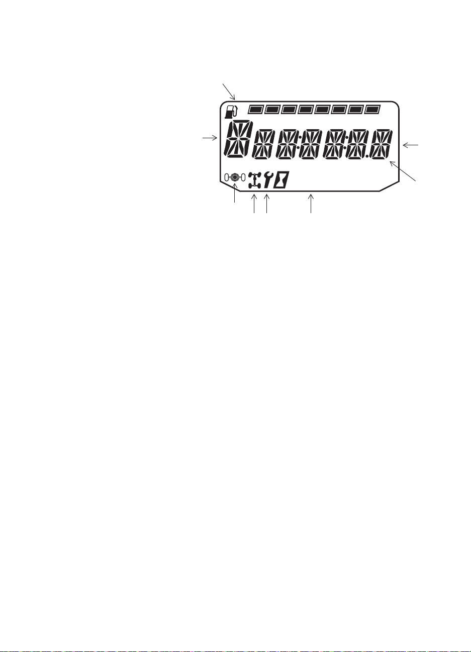
Instrument Cluster
Rider Information Center
The rider information center is
located in the instrument cluster. All
segments will light up for one
second at start-up. If the instrument
cluster fails to illuminate, a battery
over-voltage may have occurred
and the instrument cluster may have
shut off to protect the electronic
speedometer. If this occurs, take the
vehicle to your POLARIS dealer for
proper diagnosis.
The information center is set to
display standard units of
measurement and a 12-hour clock at
the factory. To change to metric
and/or a 24-hour clock, see page 31.
1. Gear Indicator - This indicator displays gear shifter position.
H = High Gear
L = Low Gear
N = Neutral
R = Reverse Gear
-- = Gear Signal Error (or shifter between gears)
2. Fuel Gauge - The segments of the fuel gauge show the level of fuel in the fuel tank.
When the last segment clears, a low fuel warning is activated. All segments including
the fuel icon will flash. Refuel immediately.
Tip: If the fuel icon fails to display, an open or short circuit has occurred in the fuel sensor circuit. See
your dealer.
3. Information Display Area - This area displays odometer, trip meter, engine hour meter
and programmable service hour interval.
4. Under / Over V o ltage - This warning usually indicates that the vehicle is operating at an
RPM too low to keep the battery charged. It may also occur when the engine is at idle
and high electrical load (lights, cooling fan, accessories) is applied. Drive at a higher
RPM or recharge the battery to clear the warning.
5. Clock - The clock displays time in a 12-hour or 24-hour format. See page 31 for
resetting instructions.
6. Service Indicator - A flashing wrench symbol alerts the operator that the preset service
interval has been reached. The vehicle should be brought to your dealer for scheduled
maintenance. See page 31 for resetting instructions.
7. 4X4 Indicator - This indicator illuminates when the 4X4 system is engaged (switch is
on 4X4).
8. Turf Mode Indicator - This indicator illuminates when the operator unlocks the
differential. See page 48.
Trip 1
km
:
88
88
FE
RPM
mi
30
Page 33

FEATURES AND CONTROLS
Instrument Cluster
Rider Information Center
Use the MODE button to toggle through the information area options.
Display Units (Standard/Metric)
The display can be changed to display either standard or metric units of measurement.
Tip: To exit the set-up mode at any time, wait 10 seconds.The display automatically exits and returns to
the odometer display.
Standard Di splay Metric Display
Distance Miles Kilometers
Fuel U.S. Gallons Liters, Imperial Gallons
Temperature Fahrenheit Celsius
Time 12-Hour Clock 24-Hour Clock
1. Turn the key to the OFF position.
2. Press and hold the MODE button while turning the key to the ON position.
3. When the display flashes the distance setting, tap the MODE button to advance to the
desired setting.
4. Press and hold the MODE button to save the setting and advance to the next display
option.
5. Repeat the procedure to change remaining display settings.
Clock Mode
Tip: The clock must be reset any time the battery has been disconnected or discharged.
1. Turn the key to the ON position. Use the MODE button to toggle to the odometer
display.
2. Press and hold the MODE button until the hour segment flashes. Release the button.
3. With the segment flashing, tap the MODE button to advance to the desired setting.
4. Press and hold the MODE button until the next segment flashes. Release the button.
5. Repeat steps 3-4 twice to set the 10-minute and 1-minute segments. After completing the
1-minute segment, step 4 will save the new settings and exit the clock mode.
6. Turn the key to the OFF position.
31
Page 34

FEATURES AND CONTROLS
Instrument Cluster
Rider Information Center
Odometer Mode
The odometer records and displays the distance traveled by the vehicle.
Trip Meter Mode
The trip meter records the distance traveled by the vehicle if reset before each trip. To reset,
select the trip meter mode. Press and hold the MODE button until the meter resets to zero. In
the Rider Information Center, the trip meter display contains a decimal point, but the
odometer displays without a decimal point.
Hour Meter Mode
This mode logs the total hours the engine has been in operation.
Tachometer Mode
The engine RPM is displayed digitally.
Tip: Small fluctuations in the RPM from day to day may be normal because of changes in humidity,
temperature and elevation.
Programmable Service Interval
When the hours of engine operation equal the programmed service interval setting, the
wrench icon will flash for 5 seconds each time the engine is started. When this feature is
enabled, it provides a convenient reminder to perform routine maintenance. The service
interval is programmed at 50 hours at the factory. Use the following procedure to change the
service interval.
1. Press the MODE button until remaining service hours display.
2. Press and hold the MODE button.
3. When the service hours flash, press and release the MODE button to advance the hours
to the desired setting (including OFF). Press and hold the MODE button to set the new
service hour interval.
Diagnostic Display Mode
The EFI diagnostic display mode is for informational purposes only. Please see your
POLARIS dealer for all major repairs.
The diagnostic mode is accessible only when the check engine warning indicator activates
after the key has been turned on. Leave the key on if you want to view the active code
(failure code).
The diagnostic mode becomes inaccessible if the key is turned off and on and the warning
indicator is no longer active. This allows the determination of persistent as well as
intermittent faults.
Inactive codes are stored in the history of the unit.
32
Page 35
FEATURES AND CONTROLS
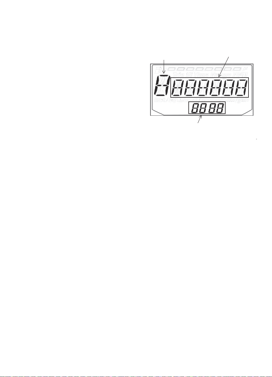
Suspect Parameter
Number (SPN)
Error Code
Number (0-9)
Failure Mode Indicator (FMI)
Instrument Cluster
Rider Information Center
Engine Error Codes
The error screen displays only when the
CHECK ENGINE light is on or when it goes
on and off during one ignition cycle. Error
codes are not stored. When the key is turned
OFF, the code and message is lost, but will
reappear if the fault reoccurs after restarting the
engine.
If the CHECK ENGINE light illuminates,
retrieve the error codes from the display.
1. If the error codes are not displayed, use the
MODE button to toggle until “Ck ENG”
displays on the main line of the display.
2. Press and hold the MODE button to enter
the diagnostics code menu.
3. Record the three numbers displayed in the gear position, clock and odometer displays.
4. Press the MODE button to advance to the next error code.
5. Press and hold the MODE button to exit the diagnostics code menu.
6. See an authorized POLARIS dealer for code details and diagnosis.
33
Page 36

OPERATION
WARNING
Failure to operate the vehicle properly can result in a collision, loss of control, accident or rollover,
which may result in serious injury or death. Read and understand all safety warnings outlined in the
safety section of this owner’s manual.
Break-In Period
The break-in period for your new RANGER is the first twenty hours of operation, or the time
it takes to use the first two tanks full of fuel. No single action on your part is as important as
a proper break-in period. Careful treatment of a new engine will result in more efficient
performance and longer life for the engine. Perform the following procedures carefully.
NOTICE: Excessive heat build-up during the first three hours of operation will damage close-fitted
Engine and Drivetrain Break-in
1. Fill the fuel tank with fuel. Review the fuel warnings on page 18.
2. Check the oil level. Add the recommended oil as needed to maintain the oil level in the
3. Drive slowly at first. Select an open area that allows room to familiarize yourself with
4. Vary throttle positions. Do not operate at sustained idle.
5. Perform regular checks on fluid levels, controls and areas outlined on the daily pre-ride
6. Pull only light loads.
7. Check fluid levels of transmission and all gearcases after the first 25 hours of operation
8. Inspect and adjust park brake cable tension after the first 25 hours of operation and every
engine parts. Do not operate at full throttle or high speeds for extended periods during the
first three hours of use.
normal (safe) operating range.
vehicle operation and handling.
inspection checklist. See page 35. During the break-in period, change both the oil and
the filter at 25 hours.
and every 100 hours thereafter.
100 hours thereafter to ensure proper cable tension. See page 80.
PVT Break-in (Clutches/Belt)
A proper break-in of the clutches and drive belt will ensure a longer life and better
performance. Break in the clutches and belt by operating at slower speeds during the breakin period as recommended. Pull only light loads. Avoid aggressive acceleration and high
speed operation during the break-in period.
If a belt fails, always clean any debris from the duct and from the engine compartment.
34
Page 37

OPERATION
Pre-Ride Inspection
Failure to inspect and verify that the vehicle is in safe operating condition before operating
increases the risk of an accident. Always inspect the vehicle before each use to make sure it's
in safe operating condition.
Item Remarks Page
Brake system/pedal travel Ensure proper operation 24
Brake fluid Ensure proper level 79
Front suspension Inspect, lubricate if necessary 62
Rear suspension Inspect, lubricate if necessary 62
Steering Ensure free operation 80
Tires Inspect condition and pressure 81
Wheels/fasteners Inspect, ensure fastener tightness 81
Frame nuts, bolts, fasteners Inspect, ensure tightness Fuel and oil Ensure proper levels 30
Coolant level Ensure proper level 73
Coolant hoses Inspect for leaks Throttle Ensure proper operation 78
Indicator lights/switches Ensure operation 23
Air filter, pre-filter Inspect, clean 76
Air box sediment tube Drain deposits whenever visible 76
Headlamp Check operation, apply POLARIS dielectric grease
Brake light/tail lamp Check operation, apply POLARIS dielectric grease
Seat Belts Check length of belt for damage, check latches for
Cab nets (or doors) Check for wear or damage, ensure proper installation 26
when lamp is replaced
when lamp is replaced
proper operation
79
63
83
83
27
35
Page 38

OPERATION
Starting the Engine
1. Always start the engine outdoors or in a well-ventilated area.
2. Sit in the driver's seat and fasten the seat belt. Secure the cab nets (or doors).
3. Apply the brakes. Engage the park brake.
4. Shift the transmission to neutral.
5. Do not press the throttle pedal while starting the engine. Turn the ignition key past the
ON/RUN position to ST ART. Engage the starter for a maximum of five seconds. Release
the key when the engine starts.
6. If the engine does not start within five seconds, release the ignition switch and wait five
seconds. Repeat steps 5 and 6 until the engine starts.
7. Vary the engine RPM slightly with the throttle to aid in warm up until the engine idles
smoothly.
NOTICE: Operating the vehicle immediately after starting could cause engine damage. Allow the
Stopping the Engine
1. Release the throttle pedal completely and brake to a complete stop.
2. Turn the engine off.
3. Engage the park brake.
WARNING! A rolling vehicle can cause serious injury. Always engage the park brake after stopping the
engine.
engine to warm up for several minutes before operating the vehicle.
Braking
1. Release the throttle pedal completely.
2. Press on the brake pedal evenly and firmly.
3. Practice starting and stopping (using the brakes) until you're familiar with the controls.
Tip: When the throttle pedal is released completely and the engine speed drops near an idle, the
vehicle has no engine braking.
36
Page 39

OPERATION
Driving Procedure
1. Wear a helmet, eye protection,
gloves, long-sleeve shirt, long
pants and over-the-ankle boots.
2. Perform the pre-ride
inspection. See page 35.
3. Sit in the driver's seat and
fasten the seat belt.
4. Always use the cab nets (or
doors) while riding in this
vehicle.
5. Start the engine and allow it to
warm up.
6. Apply the service brakes and
shift the transmission into gear.
7. Check your surroundings and determine your path of travel.
8. Release the park brake.
9. Keeping both hands on the steering wheel, slowly release the brakes and depress the
throttle with your right foot to begin driving.
10. Drive slowly. Practice maneuvering and using the throttle and brakes on level surfaces.
11. Do not carry a passenger until you have at least two hours of driving experience with this
vehicle.
37
Page 40

OPERATION
Driving with a Passenger
1. Perform the pre-ride inspection. See page 35.
2. Make sure all passengers are at least 12 years of age and tall enough to comfortably and
safely sit in a passenger seat with the seat belt secured, put both feet on the floor and
grasp the hand hold.
3. Make sure all passengers are wearing helmet, eye protection, gloves, long-sleeve shirt,
long pants and over-the-ankle boots.
4. Make sure all passengers secure their seat belt.
5. Make sure all cab nets (or doors) are properly secured.
6. Do not carry more than the recommended number of passengers for your vehicle. See
page 10.
7. Allow a passenger to ride only in a passenger seat.
8. Slow down. Always travel at a speed appropriate for your skills, your passengers’ skills,
and operating conditions. Avoid unexpected or aggressive maneuvers that could cause
discomfort or injury to a passenger.
9. Vehicle handling may change with a passenger and/or cargo on board. Allow more time
and distance for braking.
10. Always follow all operating guidelines as outlined on safety labels and in this manual.
38
Page 41
OPERATION
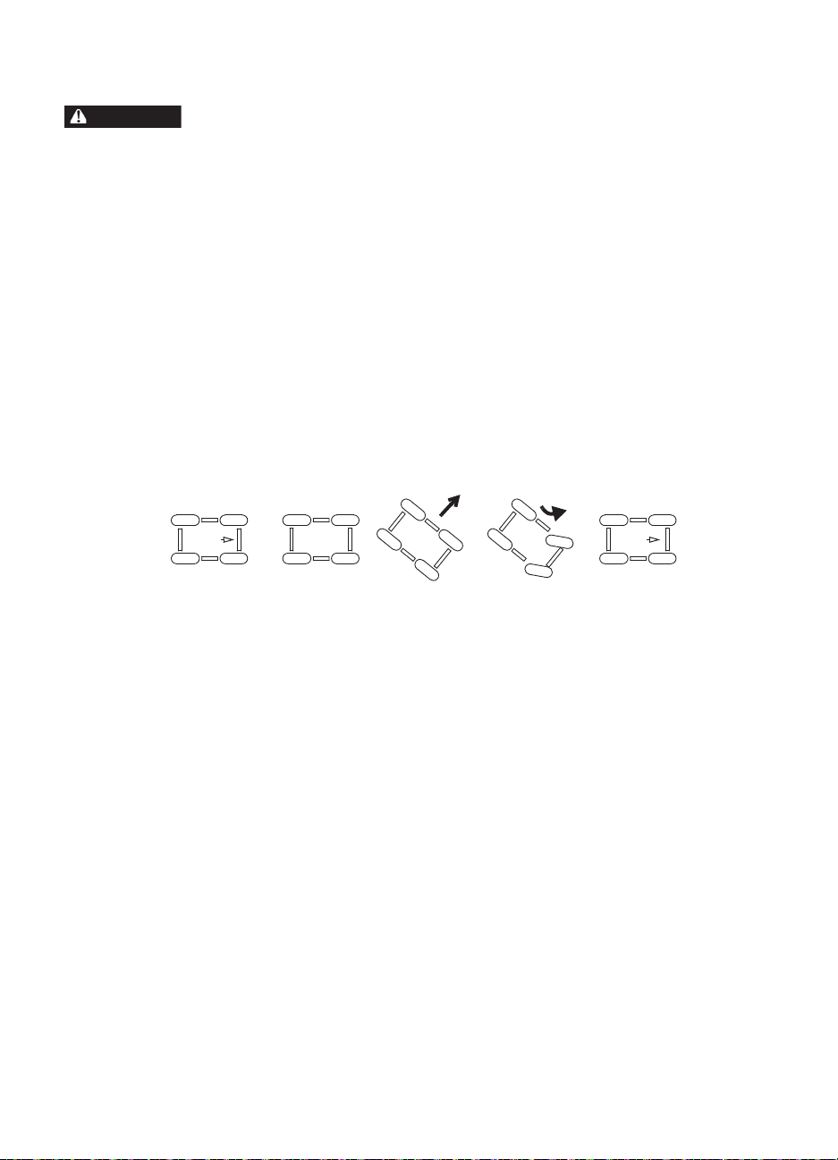
WARNING
Sideways
skid
Turn in
direction of
skid
Driving on Slippery Surfaces
Skidding or sliding can cause loss of control or rollover (if tires regain traction unexpectedly). When
operating on slippery surfaces such as ice or loose gravel, reduce speed and use extra caution to
reduce the chance of skidding or sliding out of control. Do not operate on excessively slippery surfaces.
Whenever riding on slippery surfaces such as wet trails or loose gravel, or during freezing
weather, follow these precautions:
1. Do not operate on excessively rough, slippery or loose terrain.
2. Slow down before entering slippery areas.
3. Maintain a high level of alertness, reading the trail and avoiding quick, sharp turns,
which can cause skids.
4. Engage all-wheel drive before wheels begin to lose traction.
NOTICE: Severe damage to the drive train may occur if the AWD is engaged while the wheels are
5. Correct a skid by turning the steering wheel in the direction of the skid. Never apply the
spinning. Always allow the wheels to stop spinning before engaging AWD.
brakes during a skid.
39
Page 42

OPERATION
Driving Over Obstacles
Follow these precautions when operating
over obstacles:
1. Always check for obstacles before
operating in a new area.
2. Look ahead and learn to read the terrain.
Be constantly alert for hazards such as
logs, rocks and low hanging branches.
3. Travel slowly and use extra caution
when operating on unfamiliar terrain.
Not all obstacles are immediately
visible.
4. Avoid operating over large obstacles
such as large rocks and fallen trees. If
unavoidable, use extreme caution and
operate slowly.
5. Always have all passengers dismount and move away from the vehicle before operating
over an obstacle that could cause a rollover.
40
Page 43

OPERATION
Driving Uphill
Whenever traveling uphill, follow these precautions:
1. Always travel straight uphill.
2. Avoid excessively steep hills.
3. Keep both feet on the floor.
4. Always check the terrain carefully before
ascending any hill.
5. Never climb hills with excessively slippery or
loose surfaces.
6. Proceed at a steady rate of speed and throttle
opening. Never open the throttle suddenly.
7. Never go over the crest of a hill at high speed.
An obstacle, a sharp drop, or another vehicle
or person could be on the other side of the hill.
Driving on a Sidehill (Sidehilling)
Driving on a sidehill is not recommended. Improper procedure could cause loss of control or
rollover. Avoid crossing the side of any hill unless absolutely necessary.
If crossing a sidehill is unavoidable, follow these precautions:
1. Slow down.
2. Exercise extreme caution.
3. Avoid crossing the side of a steep hill.
Driving Downhill
When driving downhill, follow these
precautions:
1. Avoid excessively steep hills.
2. Drive straight downhill. Avoid descending
a hill at an angle, which would cause the
vehicle to lean sharply to one side. Travel
straight downhill when possible.
3. Slow down.
4. Apply the brakes slightly to aid in slowing.
41
Page 44

OPERATION
Driving Through Water
Your POLARIS RANGER can operate through water up to a maximum recommended depth
equal to the floorboards.
NOTICE: Immersion can result in major damage if the vehicle isn't serviced correctly and promptly.
Follow these procedures when operating
through water:
1. Determine water depths and current
2. Choose a crossing where both banks
3. Proceed slowly , avoiding rocks and
4. Avoid operating through deep or fast-
WARNING! The large tires on your RANGER
may cause the vehicle to float in deep or fastflowing water, which could result in loss of
control and lead to serious injury or death.
Never cross deep or fast-flowing water with your
RANGER.
5. After leaving water, always dry the
NOTICE: After running your vehicle in water, it's critical that you perform the services outlined in the
After immersion, always take the vehicle to your dealer service. Do not start the engine! If it's
impossible to bring the vehicle to your dealer before starting the engine, perform the service
outlined on page 76, and take the vehicle to your dealer at the first opportunity.
before entering water.
have gradual inclines.
obstacles.
flowing water.
Floorboard
brakes by applying light pressure to the
pedal repeatedly until braking action is
normal.
Periodic Maintenance Chart beginning on page 59. Give special attention to engine oil,
transmission oil, all gearcase fluids, and all grease fittings.
42
Page 45

OPERATION
Driving in Reverse
Follow these precautions when operating in reverse:
1. Always check for obstacles or people behind the
vehicle. Always inspect left and right fields of
vision before backing.
2. Always avoid backing downhill.
3. Back slowly.
4. Apply the brakes lightly for stopping.
5. Avoid turning at sharp angles.
6. Never open the throttle suddenly.
Parking the Vehicle
1. Apply the brakes. Stop the vehicle on a level
surface.
2. When parking inside a garage or other structure, be sure that the structure is well
ventilated and that the vehicle is not close to any source of flame or sparks, including
any appliance with pilot lights.
3. Turn the engine off.
4. Engage the park brake.
5. Remove the ignition switch key to prevent unauthorized use.
Parking on an Incline
Avoid parking on an incline if possible. If it's
unavoidable, follow these precautions:
1. Apply the brakes.
2. Place the transmission in gear.
3. Engage the park brake.
4. Turn the engine off.
5. Block the rear wheels on the downhill side.
43
Page 46

OPERATION
WARNING
Hauling Cargo
Hauling cargo improperly can alter vehicle handling and may cause loss of control or brake instability,
which can result in serious injury or death. Always follow these precautions when hauling cargo:
Never exceed the maximum weight capacity of the vehicle. When determining the weight you are
adding to the vehicle, include the weight of the operator, passenger, accessories, loads in the rack or
box and the load on the trailer tongue. The combined weight of these items must not exceed the
maximum weight capacity .
REDUCE SPEED AND ALLOW GREATER DISTANCES FOR BRAKING WHEN HAULING CARGO.
Always load the cargo box with the load as far forward and as low as possible.
When operating over rough or hilly terrain, reduce speed and cargo to maintain stable driving
conditions.
Always operate the vehicle with extreme care when hauling or towing loads.
Slow down and drive in the lowest gear available.
SECURE ALL LOADS BEFORE OPERATING. Unsecured loads can create unstable operating
conditions, which could result in loss of control of the vehicle.
OPERATE ONLY WITH STABLE AND SAFELY ARRANGED LOADS. When handling off-centered
loads that cannot be centered, securely fasten the load and operate with extra caution. Always attach
the tow load to the hitch point designated for your vehicle.
HEAVY LOADS CAN CAUSE BRAKING AND CONTROL PROBLEMS. Use extreme caution when
applying brakes with a loaded vehicle. Avoid terrain or situations that may require backing dow nhill.
USE EXTREME CAUTION when operating with loads that extend over the rack sides. Stability and
maneuverability may be adversely affected, causing vehicle rollover.
DO NOT TRAVEL FASTER THAN THE RECOMMENDED SPEEDS. Vehicle should never exceed 10
MPH (16 km/h) while towing a load on a level grass surface. Vehicle speed should never exceed 5
MPH (8 km/h) when towing loads in rough terrain, while cornering, or while ascending or descending a
hill.
Load Capacity
The RANGER has been designed to carry or tow specific capacities. Always read and
understand the load distribution warnings listed on the warning labels. The total load
(operator, passenger, accessories, cargo and weight on hitch) must not exceed the maximum
weight capacity of the vehicle. See page 12.
WARNING! Driving with passengers in the cargo box can
result in severe injury or death. Never allow passengers to
ride in the cargo box. Passengers must always ride in the
cab with seat belts fastened securely.
44
Page 47

OPERATION
Towing Loads
Towing improperly can alter vehicle handling and may cause loss of control or brake
instability. Always follow these precautions when towing:
1. Never load more than 150 lbs. (68.1 kg) tongue weight on the towing bracket.
2. Always shift to low gear for towing.
3. When towing a disabled RANGER vehicle, place the disabled vehicle’s transmission in
neutral. Do not operate the vehicle faster than 10 MPH (16 km/h) when towing.
4. Do not operate the vehicle faster than 10 MPH (16 km/h) when towing. See page 44.
Towing a trailer increases braking distance.
5. Do not tow more than the recommended weight for the vehicle. See the towing capacity
chart below and the specifications charts beginning on page 94.
6. Attach a trailer to the trailer hitch bracket only. Do not attach a trailer to any other
location or you may lose control of the vehicle.
7. Never tow a trailer on a grade steeper than 15°.
Model Total Towed
RANGER 4x4 2000 lbs. (907 kg) 850 lbs. (386 kg) 150 lbs. (68.1 kg) 10 MPH (16 km/h)
RANGER 6x6 2000 lbs. (907 kg) 850 lbs. (386 kg) 150 lbs. (68.1 kg) 10 MPH (16 km/h)
RANGER CREW 2000 lbs. (907 kg) 850 lbs. (386 kg) 150 lbs. (68.1 kg) 10 MPH (16 km/h)
Load Weight
(Level Ground)
Total Towed
Load Weight
(15° grade)
Total Hitch
Vertical
Weight
Maximum
Towing
Speed
Belt Life
To extend belt life, use the lowest gear possible when hauling or towing heavy cargo.
45
Page 48

OPERATION
Dumping the Cargo Box
1. Select a level site to dump the cargo box. Do
not attempt to dump or unload the vehicle
while parked on an incline.
2. Apply the brakes. Place the transmission in
gear. Engage the park brake.
3. Dismount the vehicle.
4. Ensure that the cargo is positioned evenly or
toward the front of the cargo box.
5. Release the tailgate by pulling up on the
tailgate latch.
WARNING! If the weight distribution on the box is
located toward the rear of the box when the release
lever is pulled forward, the box may dump unexpectedly
and cause serious injury to the operator or bystanders.
Never operate the dump lever without ensuring that the
load is positioned evenly or at the front of the box.
6. Stand clear and pull up on the cargo box release lever. Lift the front of the cargo box to
dump the cargo.
7. Lower the cargo box and push down securely to latch.
WARNING! Operating the vehicle while th e cargo box is raised could result in severe injury. The box
could close unexpectedly and cause injury to the driver or passenger. The rear tires will also catch the
rear of a raised box, damaging the vehicle and creating hazardous driving conditions. Never operate
this vehicle with the cargo box in the raised position.
Release Lever
46
Page 49

OPERATION
All Wheel Drive (AWD)
Engaging A WD
Press the top of the switch to engage All Wheel Drive
(AWD). The 4X4 indicator illuminates in the rider
information center to indicate that the vehicle is in
AW D. See page 30.
When the AW D switch is on, the front wheels will
Differential Lock
automatically engage any time the rear wheels lose
traction. When the rear wheels regain traction, the
Differential Unlock
front wheels will automatically disengage. There is
no limit to the length of time the vehicle may remain
in AWD.
Tip: The AWD switch may be turned on or off while the vehicle is moving.
Engage the AWD before getting into conditions where front wheel drive may be needed. If
the rear wheels are spinning, release the throttle before switching to AWD.
NOTICE: Switching to AWD while the rear wheels are spinning may cause severe drive shaft and
clutch damage. Always switch to AWD while the rear wheels have traction or are at rest.
Disengaging AWD
Move the AW D switch to the center or bottom position to disengage AWD. If the switch is
turned off while the front hubs are driving, they will not release until the rear wheels regain
traction.
In some situations, the front gearcase may remain locked after turning the AWD switch off.
If this occurs, you may notice increased steering effort and some vehicle speed restriction.
Perform the following procedure to unlock the front gearcase.
1. Stop the vehicle.
2. Operate in reverse for at least 10 feet (3 m).
3. Stop completely.
4. Shift into low gear and drive forward.
5. If the front gearcase remains locked after following these instructions, see your dealer
for service.
AWD
47
Page 50
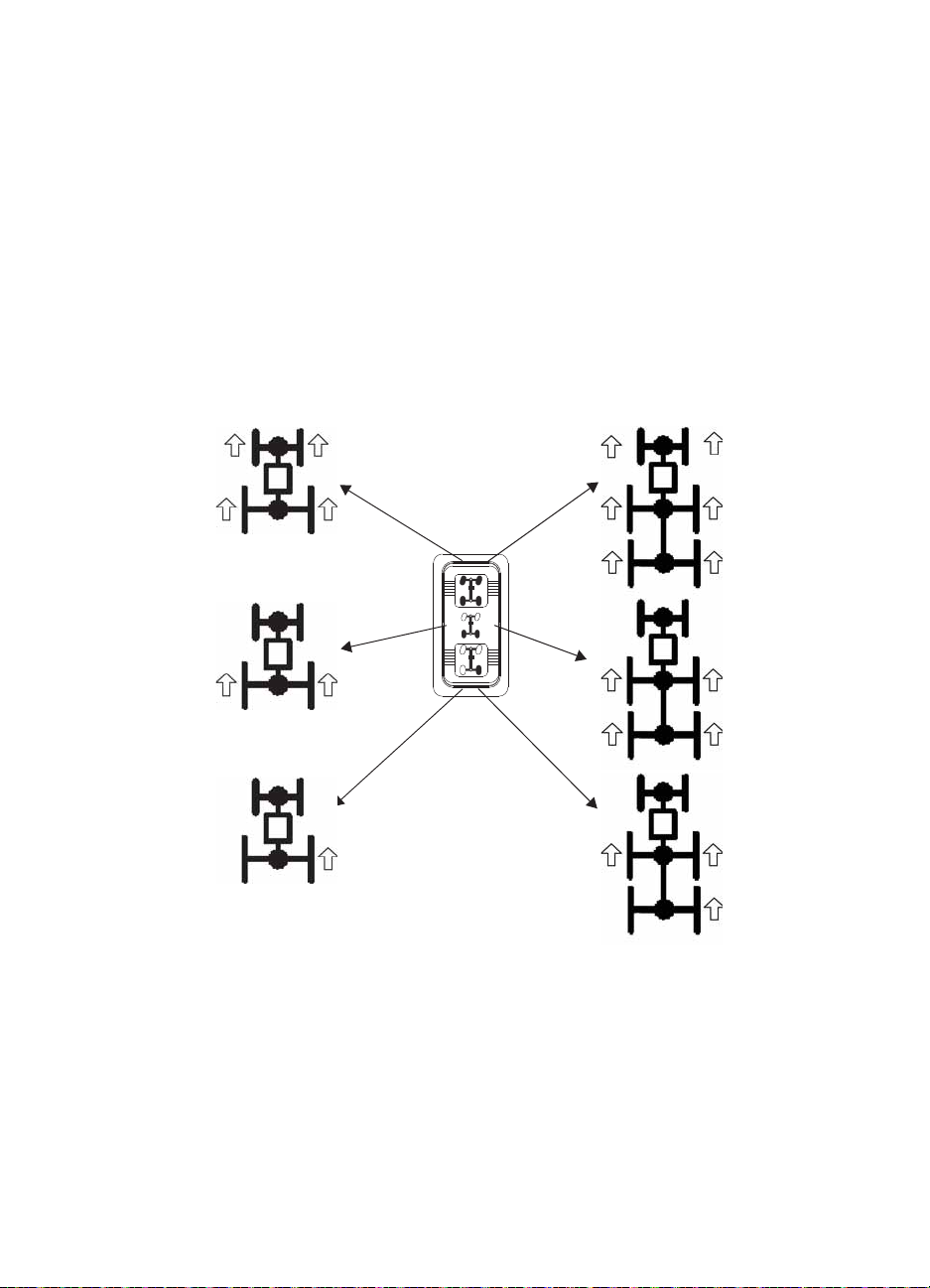
OPERATION
All Wheel Drive (AWD)
Locking the Differential
NOTICE: Damage to the differential can occur if it is engaged while the vehicle is traveling at high
Locking the differential in slippery or low traction conditions helps improve traction. Move
the rocker switch to the center position (2WD) to lock the differential and operate in rear
wheel drive. On 6X6 models, all four rear wheels will be drive wheels.
Press the bottom of the switch to unlock the differential and allow the rear drive wheels to
operate independently. This mode of operation is well suited to turf driving or whenever
aggressive traction is not required. On 6X6 models, the center wheels will remain drive
wheels.
speeds or while the rear wheels are spinning. Slow the vehicle to nearly stopped before
engaging the differential.
4X4 Models
6X6 Models
48
Page 51

WINCH GUIDE
WARNING
These safety warnings and instructions apply if your vehicle came equipped with a winch or
if you choose to add an accessory winch to your vehicle.
Improper winch use can result in SEVERE INJURY or DEATH. Always follow all winch instructions and
warnings in this manual.
Your winch may have a cable made of either wire rope or specially designed synthetic rope.
The term “winch cable” will be used for either unless noted otherwise.
Winch Safety Precautions
1. Read all sections of this manual.
2. Never use alcohol or drugs before or while operating the winch.
3. Never allow children under 16 years of age to operate the winch.
4. Always wear eye protection and heavy gloves when operating the winch.
5. Always keep body , hair, clothing and jewelry clear of the winch cable, fairlead and hook
when operating winch.
6. Never attempt to “jerk” a load attached to the winch with a moving vehicle. See the
Shock Loading section on page 56.
7. Always keep the area around the vehicle, winch, winch cable and load clear of people
(especially children) and distractions while operating the winch.
8. Always turn the vehicle ignition power OFF when it and the winch are not being used.
9. Always be sure that at least five (5) full turns of winch cable are wrapped around the
winch drum at all times. The friction provided by this wrapped cable allows the drum to
pull on the winch cable and move the load.
10. Always apply your vehicle’s park brake and/or park mechanism to hold the vehicle in
place during winching. Use wheel chocks if needed.
11. Always align the vehicle and winch with the load directly in front of the vehicle as much
as possible. Avoid winching with the winch cable at an angle to the winching vehicle’s
centerline whenever possible.
12. If winching at an angle is unavoidable, follow these precautions:
A. Look at the winch drum occasionally. Never let the winch cable “stack” or accumulate at one
end of the winch drum. Too much winch cable at one en d of the winch drum can damage the
winch and the winch cable.
B. If stacking occurs, stop winching. Follow step 15 on page 54 to feed and rewind the cable
evenly before continuing the winch operation.
49
Page 52

WINCH GUIDE
Winch Safety Precautions
13. Never winch up or down at sharp angles. This can destabilize the winching vehicle and
possibly cause it to move without warning.
14. Never attempt to winch loads that weigh more than the winch’s rated capacity.
15. The winch motor may become hot during winch use. If you winch for more than 45
seconds, or if the winch stalls during operation, stop winching and permit the winch to
cool down for 10 minutes before using it again.
16. Never touch, push, pull or straddle the winch cable while
winching a load.
17. Never let the winch cable run through your hands, even if
wearing heavy gloves.
18. Never release the clutch on the winch when the winch cable is
under load.
19. Never use the winch for lifting or transporting people.
20. Never use the winch to hoist or suspend a vertical load.
21. Never immerse or submerse your winch in water. Take your winch to your dealer for
service if this occurs.
22. Always inspe ct your winch and winch cable before each use.
23. Never winch the hook fully into the winch. This can cause damage to winch
components.
24. Unplug the remote control from the vehicle when the winch is not in use to prevent
inadvertent activation and use by unauthorized persons.
25. Never grease or oil the winch cable. This will cause the winch cable to collect debris that
will shorten the life of the cable.
50
Page 53

WINCH GUIDE
WARNING
Winch Operation
Read the Winch Safety Precautions in the preceding pages before using your winch.
Tip: Consider practicing the operation and use of your winch before you actually need to use it in the
field.
Improper winch use can result in SEVERE INJURY or DEATH. Always follow all winch instructions and
warnings in this manual.
Each winching situation is unique.
• Take your time to think through the winching you are about to do.
• Proceed slowly and deliberately.
• Never hurry or rush during winching.
• Always pay attention to your surroundings.
• You may need to change your winching strategy if it is not working.
• Always remember that your winch is very powerful.
• There are simply some situations that you and your winch will not be able to deal with. Do not be
afraid to ask others to help when this happens.
1. Always inspect the vehicle, winch, winch cable and winch controls for any signs of
damage or parts in need of repair or replacement before each use. Pay particular
attention to the first 3 feet (1 meter) of winch cable if the winch is being used (or has
been used) for lifting an accessory plow assembly. Promptly replace any worn or
damaged cable.
2. Never operate a winch or a vehicle in need of repair or service.
3. Always apply your vehicle’s park brake and/or
park mechanism to hold the vehicle in place
during winching. Use wheel chocks if needed.
Hook Strap
51
Page 54

WINCH GUIDE
NO YES
Winch Operation
4. Always use the hook strap when handling the hook.
WARNING! Never put your fingers into the hook. This could lead
to SEVERE INJURY.
A. Attach the hook itself onto the load or use a tow strap or
chain to secure the load to the winch cable.
Tip: A “tow strap” is NOT intended to stretch. A “recovery strap”
is designed to stretch.
WARNING! Never use a recovery strap when winching due to
the excessive energy that can be released if the winch cable breaks. This can result in SEVERE
INJURY or DEATH. See the Shock Loading section on page 56.
B. Never hook the winch cable back onto itself. This will damage the winch cable and may result
in winch cable failure.
WARNING! Replace the winch cable at the first sign of damage to prevent SEVERE INJURY or
DEAT H in the event of failure. For your safety , always replace POLARIS winch parts (including the
cable) with genuine POLARIS replacement parts available at your authorized POLARIS dealer.
C. If possible, keep the winch cable aligned with the centerline of the winching vehicle. This will
help the spooling of the winch cable and reduce the load on the fairlead.
D. If freeing a stuck vehicle by attaching to a tree, use an item such as a tow strap to avoid
damaging the tree during winch operation. Sharp cables and chains can damage and even kill
trees. Please remember to TreadLightly® (treadlightly.org).
E. Before operating the winch , be sure that the safety latch on
the winch cable hook is fully seated when the load is
attached.
F. Never operate your winch with a damaged hook or latch.
Always replace damaged parts before using the winch.
5. Never remove the hook strap from the hook.
6. Release the winch clutch and pull out the winch cable.
YES
7. Pulling out as much cable as possible maximizes the
winch’s pulling capacity. Always be sure that at least five (5) full turns of winch cable
are wrapped around the winch drum at all times. The friction provided by this wrapped
cable allows the drum to pull on the winch cable and move the load.
NO
52
Page 55

WINCH GUIDE
Winch Operation
8. Read and adhere to the following information for winch damping to ensure safe winch
use.
A. In order to absorb energy that could be released by a winch cable failure, always place a
“damper” on the winch cable. A damper can be a heavy jacket, tarp, or other soft, dense
object. A damper can absorb much of the energy released if a winch cable breaks when
winching. Even a tree limb can help as a damper if no other items are available to you.
B. Lay the damper on top of the mid-point of the winch cable length that is spooled out.
C. On a long pull, it may be necessary to stop winching so that the damper can be repositioned
to the new mid-point of the winch cable. Always release the tension on the winch cable before
repositioning the damper.
D. Avoid being directly in line with the winch cable whenever possible. Also, never permit others
to stand near or in line with the winch cable during winch operation.
9. Never hook the winch cable back onto itself. This will damage the winch cable and may
result in winch cable failure.
10. Never use straps, chains or other rigging items that are damaged or worn.
11. The ONLY time a winch-equipped vehicle should be moving when using the winch is
when that vehicle itself is stuck. The winch-equipped vehicle should NEVER be in
motion to “shock” load the winch cable in an attempt to move a second stuck vehicle.
See the Shock Loading section on page 56. For your safety , always follow these
guidelines when winching a vehicle free:
A. Release the winch clutch and spool out the necessary length of winch cable.
B. Align the winch cable as close as possible to the winching vehicle’s centerline.
C. Attach the winch cable hook to the anchor point or the stuck vehicle’s frame following
instructions in this manual.
D. Re-engage the clutch on the winch.
E. Slowly winch in the slack in the winch cable.
F. Select the proper vehicle gear to propel the stuck vehicle in the direction of winching.
G. Shift to the lowest gear available on the stuck vehicle.
H. Slowly and carefully apply vehicle throttle and winch together to free the vehicle.
I. Stop winching as soon as the stuck vehicle is able to propel itself without the help of the
winch.
J. Detach the winch cable hook.
K. Rewind the winch cable evenly back onto the winch drum following the instructions in this
manual.
12. Never attempt to winch another stuck vehicle by attaching the winch cable to a
suspension component, brush guard, bumper or cargo rack. Vehicle damage may result.
Instead, attach the winch to a strong portion of the vehicle frame or hitch.
53
Page 56

WINCH GUIDE
Winch Operation
13. Extensive winching will run down the battery on the winching vehicle. Let the winching
vehicle’s engine run while operating the winch to prevent the battery from running low if
winching for long periods.
14. The winch motor may become hot during winch use. If you winch for more than 45
seconds, or if the winch stalls during operation, stop winching and permit the winch to
cool down for 10 minutes before using it again.
15. After winching is complete, especially if winching at an angle, it may be necessary to redistribute the winch cable across the winch drum. You will need an assistant to perform
this task.
A. Release the clutch on the winch.
B. Feed out the winch cable th at is unevenly bunched up in one area.
C. Re-engage the winch clutch.
D. Have an assistant pull the winch cable tightly with about 100 lbs. (45 kg) of tension using the
hook strap.
E. Slowly winch the cable in while your assistant moves the end of the winch cable back and
forth horizontally to evenly distribute the winch cable on the drum.
F. Doing this reduces the chances of the winch cable “wedging” itself between lower layers of
winch cable.
54
Page 57

WINCH GUIDE
A
B
C
Winch Cable Care
For your safety, always replace POLARIS winch parts (including the cable) with genuine
POLARIS replacement parts available at your authorized POLARIS dealer.
WARNING! Use of worn or damaged cable could lead to sudden failure and SEVERE INJURY.
1. Always inspect your winch before each use. Inspect for worn or loose parts including
mounting hardware. Never use the winch if any part needs repair or replacement.
2. Always inspect your winch cable before each use. Inspect for worn or kinked winch
cable.
A. A kinked winch cable made of wire rope is shown at
right. Even after being “straightened out,” this cable has
already been permanently and severely damaged.
Promptly discontinue use of a winch cable in this
condition.
B. A kinked winch cable made of wire rope that has been
“straightened out” is shown at right. Even though it may
look usable, the cable has been permanently and
severely damaged. It can no longer transmit the load
that it could prior to kinking. Promptly discontinue use
of a winch cable in this condition.
C. A winch cable made of synthetic rope should be
inspected for signs of fraying. Replace the cable if
fraying is observed (shown at right). Promptly
discontinue use of a winch cable in this condition.
D. Also replace the winch cable if there are fused or
melted fibers. Such an area of the synthetic rope will
be stiff and appear smooth or glazed. Promptly
discontinue use of a winch cable in this condition.
55
Page 58

WINCH GUIDE
Shock Loading
WARNING! Your winch cable is very strong but it is NOT designed for dynamic, or “shock” loading.
Shock loading may tension a winch cable beyond its strength and cause the cable to break. The end of
a broken winch cable under such high loading can cause SEVERE INJURY or DEATH to you and other
bystanders.
Winch cables are designed to NOT absorb energy. This is true of both wire-rope and
synthetic-rope winch cables.
1. Never attempt to “jerk” a load with the winch. For example, never take up slack in the
winch cable by moving the winching vehicle in an attempt to move an object. This is a
dangerous practice. It generates high winch cable loads that may exceed the strength of
the cable. Even a slowly moving vehicle can create large shock loads in a winch cable.
WARNING! SEVERE INJURY or DEATH can result from a broken winch cable.
2. Never quickly turn the winch ON and OFF repeatedly (“jogging”). This puts extra load
on the winch, winch cable, and generates excessive heat from the motor. This is a form
of shock loading.
3. Never tow a vehicle or other object with your winch. Towing an object with a winch
produces shock loading of the cable even when towing at slow speeds. Towing from a
winch also positions the towing force high on the vehicle. This can cause instability of
the vehicle and possibly lead to an accident.
4. Never use recovery straps with your winch. Recovery straps are designed to stretch and
can store energy. This stored energy in the recovery strap is released if a winch cable
fails making the event even more hazardous. Similarly, never use elastic “bungie” cords
for winching.
5. Never use the winch to tie down a vehicle to a trailer or other transportation vehicle. This
type of use also causes shock loading that can cause damage to the winch, winch cable,
or vehicles used.
Your winch cable is designed and tested to withstand the loads produced by the winch
motor when operated from a stationary vehicle. Always remember that the winch and
winch cable are NOT designed for shock loading.
56
Page 59

WINCH GUIDE
Winch Maintenance and Service Safety
WARNING! Improper or lack of winch maintenance and service could lead to SEVERE INJURY or
DEATH. Always follow all winch instructions and warnings in this manual.
1. Always inspect your winch before each use. Inspect for worn or kinked winch cable.
Also inspect for worn or loose parts including mounting hardware.
2. Permit your winch motor to cool down prior to servicing your winch.
3. Never work on your winch without first disconnecting the battery connections to prevent
accidental activation of the winch
4. For your safety, always replace POLARIS winch parts (including the cable) with
genuine POLARIS replacement parts available at your authorized POLARIS dealer.
5. Some winch models use wire rope as the winch cable. Other winches use a specially
designed synthetic rope as the winch cable.
6. Never replace a synthetic-rope winch cable with a consumer-grade polymer rope such as
can be purchased in a hardware store. Although they may look similar, they are NOT
alike. A polymer rope not designed for winch use will stretch and store excessive energy
when winching.
WARNING! Failure of a stretched rope under winching conditions will release all of the stored energy.
This will increase the chances of SEVERE INJURY or DEATH.
57
Page 60

EMISSION CONTROL SYSTEMS
Noise Emission Control System
Do not modify the engine, intake or exhaust components, as doing so may affect compliance
with U.S.A. EPA noise control requirements (40 CFR 205) and local noise level
requirements.
Operation on Public Lands in the U.S.A.
Your POLARIS vehicle has a spark arrester that was tested and qualified to be in accordance
with the USFS standard 5100-1c. Federal law requires that this spark arrester be installed and
functional when the vehicle is operated on public lands.
Operation of off-road vehicles on public lands in the U.S.A. is regulated by 43 CFR 420.
Violations are subject to monetary penalties. Federal regulations can be viewed online at
www.gpoaccess.gov/ecfr/.
Crankcase Emission Control System
This engine is equipped with a closed crankcase system. Blow-by gases are forced back to
the combustion chamber by the intake system. All exhaust gases exit through the exhaust
system.
Exhaust Emission Control System
Exhaust emissions are controlled by engine design. An electronic fuel injection (EFI) system
controls fuel delivery. The engine and EFI components are set at the factory for optimal
performance and are not adjustable.
The emissions label is located on the frame under the seat.
Electromagnetic Interference
This spark ignition system complies with Canadian ICES-002.
This vehicle complies with the EMC requirements of European directives 97/24/EC and
2004/108/EC.
Non-ionizing Radiation: This vehicle emits some electromagnetic energy . People with active
or non-active implantable medical devices (such as heart monitoring or controlling devices)
should review the limitations of their device and the applicable electromagnetic standards
and directives that apply to this vehicle.
58
Page 61

MAINTENANCE
Periodic Maintenance Chart
Careful periodic maintenance will help keep your vehicle in the safest, most reliable
condition. Inspection, adjustment and lubrication of important components are explained in
the periodic maintenance chart.
Inspect, clean, lubricate, adjust and replace parts as necessary. When inspection reveals the
need for replacement parts, use genuine POLARIS parts available from your POLARIS
dealer.
Record maintenance and service in the Maintenance Log beginning on page 109.
Tip: Service and adjustments are important for proper vehicle operation. If you're not familiar with safe
service and adjustment procedures, have a qualified dealer perform these operations.
Vehicles subjected to heavy or severe use patterns must be inspected and serviced more
frequently.
Severe Use Definition
• Frequent immersion in mud, water or sand
• Frequent or prolonged operation in dusty environments
• Racing or race-style high RPM use
• Prolonged low speed, heavy load operation
• Extended idle
• Short trip cold weather operation
Pay special attention to the oil level. A rise in oil level during cold weather can indicate
contaminants collecting in the oil sump or crankcase. Change oil immediately if the oil level
begins to rise. Monitor the oil level, and if it continues to rise, discontinue use and determine
the cause or see your dealer.
Maintenance Chart Key
Ź Perform these operations more often for vehicles subjected to severe use.
E Emission-related service (Failure to conduct this maintenance will not void the
emissions warranty but may affect emissions.)
D Have an authorized POLARIS dealer perform these services.
WARNING! Improperly performing the procedures marked with a “D” could result in component failure
and lead to serious injury or death. Have an authorized POLARIS dealer perform these services.
59
Page 62

MAINTENANCE
Periodic Maintenance Chart
Perform all services at whichever maintenance interval is reached first.
Item Maintenance Interval
Steering
Front suspension
Rear suspension
Tires
Brake fluid level
Brake pedal travel
Brake system
Wheels/fasteners
Frame fasteners
Engine oil level
Ź
Air filter, pre-filter - Daily - Inspect; clean often; replace as needed
E
Ź
Air box sediment tube - Daily - Drain deposits when visible
E
Coolant (if applicable) - Daily - Check level daily , change coolant every
Ź Power steering unit (if equipped) - Daily - Inspect daily; clean often
Headlamp/tail lamp - Daily - Check operation; apply dielectric
Ź
Air filter, main element - Weekly - Inspect; replace as needed
E
Ź
Brake pad wear 10 H Monthly - Inspect periodically
D
Battery 20 H Monthly - Check terminals; clean; test
Ź
Engine breather filter (if equipped) 25 H Monthly - Inspect; replace if necessary
E
Ź Engine oil change (break-in) 25 H 1 M - Perform a break-in oil change at one
Ź Front Gearcase oil (if equipped) 25 H 1 M - Perform a break-in oil level check
Ź Middle Gearcase oil (if equipped) 25 H 1 M - Perform a break-in oil level check
Ź Rear gearcase oil (if equipped) 25 H 1 M - Perform a break-in oil level check
Ź Transmission oil 25 H 1 M - Perform a break-in oil level check
Park brake cable tension 25 H 1 M - Check tension, adjust
Ź General lubrication 50 H 3 M - Lubricate all fittings, pivots, cables, etc.
Shift Linkage 50 H 6 M - Inspect, lubricate, adjust
D Steering 50 H 6 M - Lubricate
Ź Front Suspension 50 H 6 M - Lubricate
Ź Rear Suspension 50 H 6 M - Lubricate
Ź Perform these procedures more often for vehicles subjected to severe use.
E Emission-Related Service
D Have an authorized POLARIS dealer perform these services.
(whichever comes first)
Hours Calendar Miles (Km)
Pre-Ride Make adjustments as need ed. See
Pre-Ride Checklist on page 35.
2 years
grease if replacing
month
Remarks
60
Page 63

Periodic Maintenance Chart
MAINTENANCE
Item Maintenance Interval
DEThrottle cable/throttle pedal 50 H 6 M - Inspect; adjust; lubricate;
E Throttle body air intake ducts/
flange
Drive belt 50 H 6 M - Inspect; adjust; replace as needed
Cooling system (if applicable) 50 H 6 M - Inspect coolant strength seasonally;
Ź Oil lines, fasteners 50 H 6 M - Inspect for leaks and loose fittings
Park brake cable tension 100 H 6 M - Check tension, adjust
Ź Engine oil change 100 H 6 M - Perform a break-in oil change at one
Ź Oil filter change 100 H 6 M - Replace with oil change
Ź Front Gearcase oil (if equipped) 100 H 12 M - Change fluid
Ź Middle Gearcase oil (if equipped) 100 H 12 M - Change fluid
Ź Rear gearcase oil (if equipped) 100 H 12 M - Change fluid
Ź Transmission oil 100 H 12 M - Change fluid
DEFuel system 100 H 12 M - Check for leaks at tank cap, lines, fuel
Ź Radiator (if applicable) 100 H 12 M - Inspect; clean external surfaces
Ź Cooling Hoses (if applicable) 100 H 12 M - Inspect for leaks
Ź Engine mounts 100 H 12 M - Inspect
Exhaust muffler/pipe 100 H 12 M - Inspect
DESpark plug 100 H 12 M - Inspect; replace as needed
(whichever comes first)
Hours Calendar Miles (Km)
replace if necessary
50 H 6 M - Inspect duct for proper sealing/air leaks
pressure test system yearly
month
valve, filter, pump, throttle body; replace
lines every two years
Remarks
D Ignition timing 100 H 12 M - Inspect
Ź Wiring 100 H 12 M - Inspect for wear, routing, security; apply
DŹClutches (drive and driven) 100 H 12 M - Inspect; clean; replace worn parts
D Front wheel bearings 100 H 12 M - Inspect; replace as needed
D Brake fluid 200 H 24 M - Change every two years
Spark arrester 300 H 36 M - Clean out
Idle speed - Adjust as needed
D Toe adjustment - Inspect periodically; adjust when parts
DŹAuxiliary brake (if equipped) - Inspect daily; adjust as needed
Headlight aim - Adjust as needed
Ź Perform these procedures more often for vehicles subjected to severe use.
E Emission-Related Service
D Have an authorized POLARIS dealer perform these services.
dielectric grease to connectors subjected to water, mud, etc.
are replaced
61
Page 64
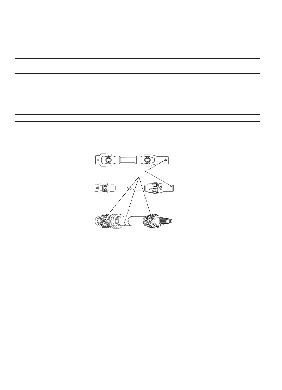
MAINTENANCE
Lubrication Recommendations
Check and lubricate all components at the intervals outlined in the Periodic Maintenance
Chart beginning on page 59, or more often under severe use, such as wet or dusty conditions.
Items not listed in the chart should be lubricated at the general lubrication interval.
Item Lube Method
Engine Oil PS-4 5W-50 4-Cycle Oil Add to proper level on dipstick. See page 63.
Brake Fluid DOT 4 Brake Fluid Maintain level between fill lines. See page 79.
Main Gearcase Oil
(Transmission)
Front Gearcase Oil Demand Drive Fluid See page 68.
Middle Gearcase Oil (6X6) ATV Angle Drive Fluid See page 69.
Rear Gearcase Oil (6X6) ATV Angle Drive Fluid See page 70.
Prop Shaft U-joints (6X6) U-Joint Grease Locate fittings and grease.
Front Prop Shaft Yoke U-Joint Grease Locate fittings and grease
AGL Gearcase Lubricant &
Transmission Fluid
6X6 Prop Shaft U-Joints
See page 67 (6X6).
See page 66 (4X4/CREW).
(3 pumps maximum).
62
Page 65

MAINTENANCE
Safe
{
Safe
Range
Check Level
on Top Side
Dipstick
Add
Engine Intake Restrictor Plate
Some RANGER 800 models are equipped with an intake restrictor plate in order to meet
vehicle class regulations. This plate MUST NOT be removed for any reason. Removal of the
intake restrictor plate will void the warranty on the vehicle.
Engine Oil
Always check and change the engine oil at the intervals outlined in the Periodic Maintenance
Chart beginning on page 59. Always change the oil filter whenever changing oil.
WARNING! Vehicle operation with insufficient, deteriorated, or contaminated engine oil will cause
accelerated wear and may result in engine seizure, accident, and injury. Always perform the
maintenance procedures as outlined in the Periodic Maintenance Chart.
Oil Recommendations
POLARIS recommends the use of POLARIS PS-4 5W-50 4-Cycle Oil or a similar oil. See
page 100 for the part numbers of POLARIS products.
NOTICE: Mixing brands or using a non-recommended oil may cause serious engine damage. Always
Always check and change the oil at the intervals outlined in the Periodic Maintenance Chart
beginning on page 59. Always use the recommended engine oil.
Oil Check
The oil dipstick and fill tube is located on the engine.
1. Position the vehicle on a level surface.
2. Remove the seat and the underseat storage box.
3. Lift the lever lock to remove the dipstick. Wipe it dry
4. Reinstall the dipstick completely, but do not lock it. The
5. Remove the dipstick and check the oil level. Maintain
Tip: Due to the dipstick entry angle into the crankcase, the oil level
6. After reinstalling the dipstick, be sure to seat the lever
7. Reinstall the underseat storage box and the seat.
use the recommended oil. Never substitute or mix oil brands.
with a clean cloth.
dipstick must be screwed completely in to keep the angle
and depth of the stick consistent.
the oil level in the safe range. Do not overfill.
will read higher on the bottom side of the dipstick. Always read
the level on the upper surface of the dipstick.
lock.
63
Page 66

MAINTENANCE
Engine Oil
Oil and Filter Change
Always change the oil and filter at the intervals outlined in the Periodic Maintenance Chart
beginning on page 59. Always change the oil filter whenever changing oil.
1. Position the vehicle on a level surface.
2. Run the engine for two to three minutes until warm. Stop the engine.
3. Clean the area around the drain plug.
4. Place a drain pan beneath engine crankcase.
CAUTION! Hot oil can cause burns to skin. Do not allow hot oil to contact skin.
5. Remove the drain plug.
6. Allow the oil to drain completely.
7. Reinstall the sealing washer on the drain plug. The sealing surfaces on drain plug and
crankcase should be clean and free of burrs, nicks or scratches.
8. Reinstall the drain plug. Torque to 20 ft. lbs. (27 Nm).
9. Remove the seat and the underseat storage box.
10. Place shop towels beneath the oil filter. Using an oil filter wrench, turn the filter counterclockwise to remove it.
11. Using a clean dry cloth, clean the filter sealing surface on the crankcase.
12. Lubricate the o-ring on the new filter with a film of fresh engine oil. Check to make sure
the o-ring is in good condition.
13. Install the new filter and turn by hand until the filter gasket contacts the sealing surface,
then turn and additional 1/2 turn.
14. Remove the dipstick and fill the sump with two quarts (1.9 l) of recommended oil.
15. Shift the transmission to neutral.
16. Apply the brakes. Engage the park brake.
17. Start the engine. Allow it to idle for one to two minutes.
18. Stop the engine. Inspect for leaks.
19. Check the oil level on the dipstick and add oil as necessary to bring the level to the upper
mark on the dipstick.
20. Reinstall the underseat storage box and the seat.
21. Dispose of used filter and oil properly.
64
Page 67

Gearcases
Gearcase Specification Chart
RANGER 4X4 Gearcase Specifications
MAINTENANCE
Gearcase Lubricant Capacity Fill Plug(s)
Main Gearcase
(Transmission)
Front Gearcase Demand Drive Fluid 9.3 oz.
AGL Gearcase
Lubricant &
Transmission Fluid
34 oz.
(1000 ml)
(275 ml)
Torque
12 ft. lbs.
(16.3 Nm)
8-10 ft. lbs.
(11-13.6 Nm
Drain Plug T orque
12 ft. lbs.
(16.3 Nm)
11 f t. lbs.
(15 Nm)
RANGER 6x6 Gearcase Specifications
Gearcase Lubricant Capacity Fill Plug Torque Drain Plug Torque
Main Gearcase
(Transmission)
Front Gearcase Demand Drive Fluid 9.3 oz.
Middle Gearcase ATV Angle Drive Fluid 6.75 oz.
Rear Gearcase ATV Angle Drive Fluid 18 oz.
AGL Gearcase
Lubricant &
Transmission Fluid
43.6 oz.
(1290 ml)
(275 ml)
(200 ml)
(532 ml)
12 ft. lbs.
(16.3 Nm)
8-10 ft. lbs.
(11-13.6 Nm
14 ft. lbs.
(19.4 Nm)
14 ft. lbs.
(19.4 Nm)
12 ft. lbs.
(16.3 Nm)
11 f t. lbs.
(15 Nm)
14 ft. lbs.
(19.4 Nm)
14 ft. lbs.
(19.4 Nm)
RANGER CREW Gearcase Specifications
Gearcase Lubricant Capacity Fill Plug(s)
Main Gearcase
(Transmission)
Front Gearcase Demand Drive Fluid 9.3 oz.
AGL Gearcase
Lubricant &
Transmission Fluid
34 oz.
(1000 ml)
(275 ml)
Torque
12 ft. lbs.
(16.3 Nm)
8-10 ft. lbs.
(11-13.6 Nm
Drain Plug T orque
12 ft. lbs.
(16.3 Nm)
11 f t. lbs.
(15 Nm)
65
Page 68
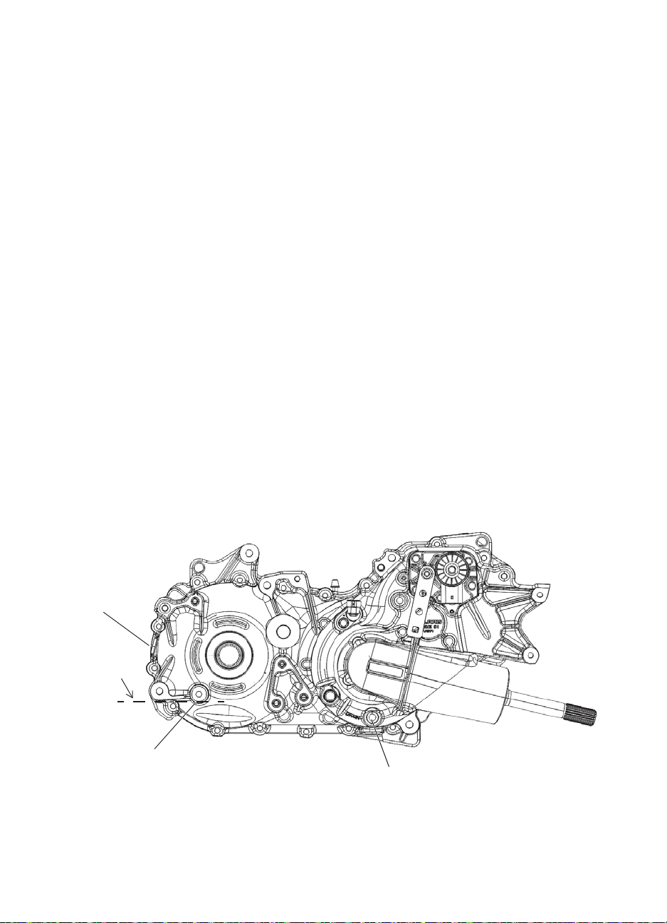
MAINTENANCE
Gearcases
Transmission (Main Gearcase) (4X4/CREW)
Always check and change the transmission oil at the intervals outlined in the Periodic
Maintenance Chart beginning on page 59. Refer to the Gearcase Specifications Chart on
page 65 for recommended lubricants, capacities and torque specifications. See page 100 for
the part numbers of POLARIS products.
Oil Check
The fill plug is located on the rear of the gearcase. A level check/alternate fill plug is located
on the side of the gearcase. Maintain the oil level even with the bottom of the level check/fill
plug hole threads.
1. Position the vehicle on a level surface.
2. Remove the level check/fill plug. Check the oil level.
3. Remove the rear fill plug and add the recommended oil as needed.
4. Reinstall both fill plugs. Torque to specification.
Oil Change
The drain plug is located near the bottom of the gearcase.
1. Remove the rear fill plug and the level check/fill plug.
2. Place a drain pan under the gearcase.
3. Remove the drain plug. Allow the oil to drain completely.
4. Clean and reinstall the drain plug. Torque to specification.
5. Add the recommended oil.
6. Reinstall both fill plugs. Torque to specification.
7. Check for leaks. Dispose of used oil properly.
66
Rear Fill
Plug
Fill Level
Level Check and
Alternate Fill Plug
Drain Plug
Page 69
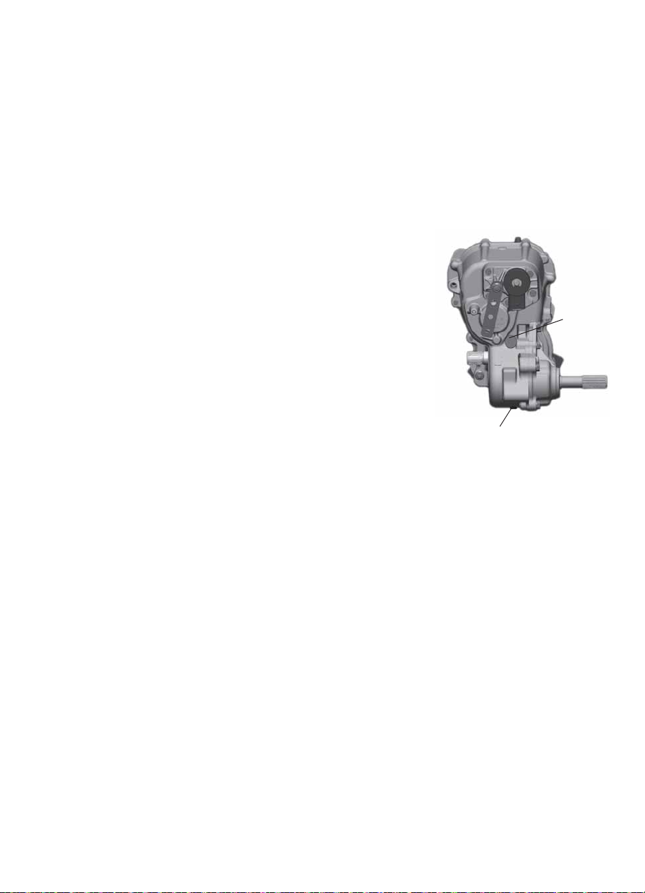
MAINTENANCE
Drain Plug
Fill
Plug
Gearcases
Transmission (Main Gearcase) (6X6)
Always check and change the transmission oil at the intervals outlined in the Periodic
Maintenance Chart beginning on page 59. Maintain the oil level even with the bottom of the
fill plug hole.
Refer to the Gearcase Specifications Chart on page 65 for recommended lubricants,
capacities and torque specifications. See page 100 for the part numbers of POLARIS
products.
Oil Check
The fill plug is located at the rear of the vehicle.
1. Position the vehicle on a level surface.
2. Remove the fill plug.
3. Check the oil level.
4. Add the recommended oil as needed.
5. Reinstall the fill plug. Torque to specification.
Oil Change
The drain plug is located on the bottom of the
transmission. Access the drain plug through the drain
hole in the skid plate.
1. Remove the fill plug.
2. Place a drain pan under the drain plug. Remove the
drain plug. Allow the oil to drain completely.
3. Wipe the magnetic end of the drain plug clean to
remove accumulated metallic filings. Install a new
sealing washer.
4. Reinstall the drain plug. Torque to specification.
5. Add the recommended oil. Do not overfill.
6. Reinstall the fill plug. Torque to specification.
7. Check for leaks. Dispose of used oil properly.
67
Page 70

MAINTENANCE
Gearcases
Front Gearcase
Always check and change the front gearcase oil at the intervals outlined in the Periodic
Maintenance Chart beginning on page 59. Maintain the oil level even with the bottom thread
of the fill plug hole.
Refer to the Gearcase Specifications Chart on page 65 for recommended lubricants,
capacities and torque specifications. See page 100 for the part numbers of POLARIS
products.
Oil Check
The front gearcase fill plug is located on the right
side of the front gearcase.
1. Position the vehicle on a level surface.
2. Remove the fill plug. Check the oil level.
3. Add the recommended oil as needed.
4. Reinstall the fill plug. Torque to specification.
Oil Change
1. Support the vehicle securely with a jackstand.
2. Remove the front tire on the driver's side.
3. Remove the fill plug.
4. Place a drain pan under the drain plug on the
bottom right-hand side.
5. Remove the drain plug. Allow the oil to drain completely.
6. Clean and reinstall the drain plug. Torque to specification.
7. Add the recommended oil.
8. Reinstall the fill plug. Torque to specification.
9. Check for leaks. Dispose of used oil properly.
Plug
Fill
Drain
Plug
68
Page 71
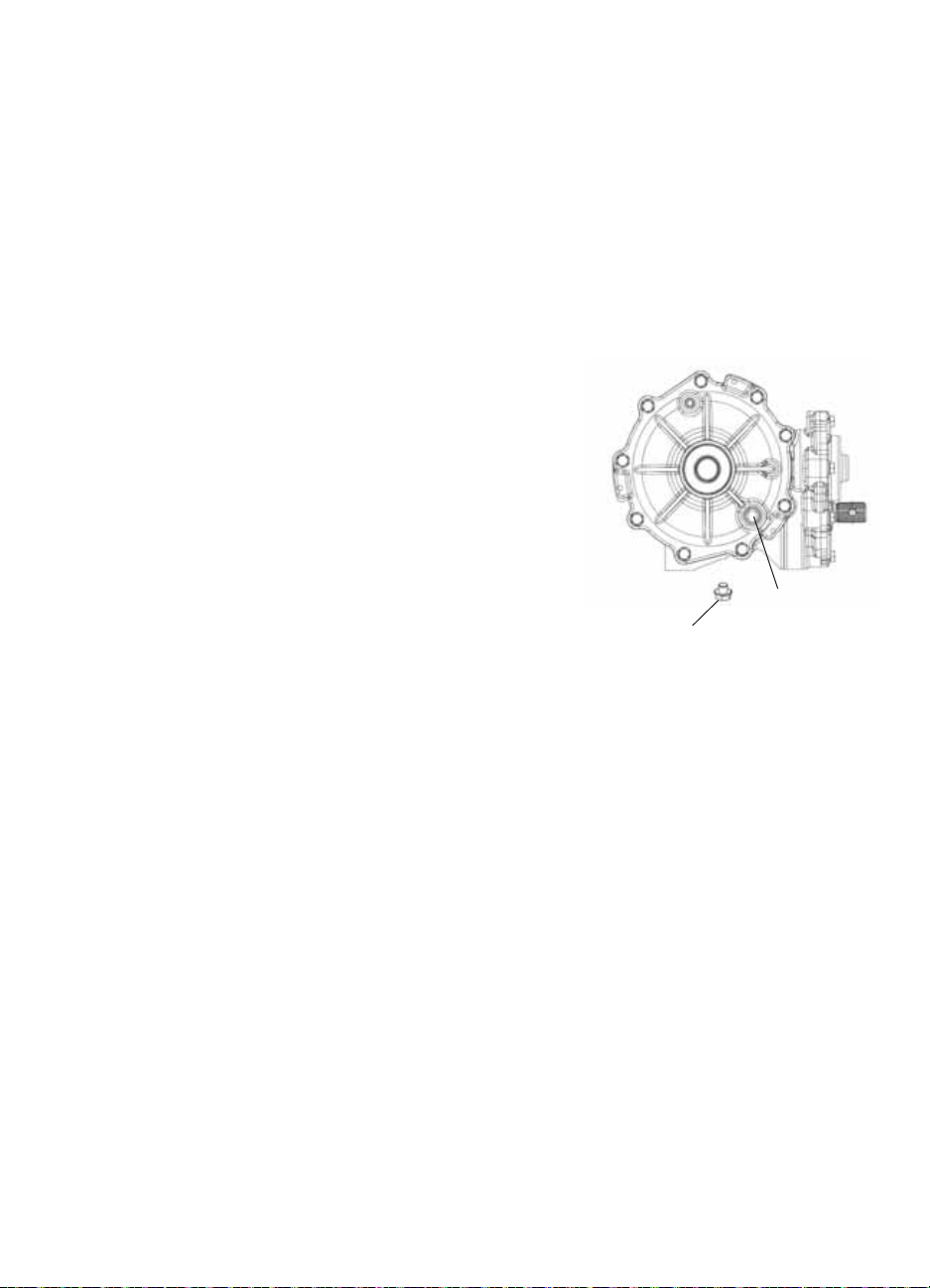
MAINTENANCE
Gearcases
Middle Gearcase (6X6)
Always check and change the middle gearcase oil at the intervals outlined in the Periodic
Maintenance Chart beginning on page 59. Maintain the oil level even with the bottom thread
of the fill plug hole.
Refer to the Gearcase Specifications Chart on page 65 for recommended lubricants,
capacities and torque specifications. See page 100 for the part numbers of POLARIS
products.
The middle gearcase fill plug is located on the side of the gearcase.
Oil Check
1. Position the vehicle on a level surface.
2. Remove the fill plug. Check the oil level.
3. Add the recommended oil as needed.
4. Reinstall the fill plug. Torque to specification.
Oil Change
1. Remove the fill plug.
2. Place a drain pan under the drain plug.
3. Remove the drain plug. Allow the oil to drain
completely.
4. Clean and reinstall the drain plug. Torque to
specification.
5. Add the recommended fluid.
6. Reinstall the fill plug. Torque to specification.
7. Check for leaks. Discard used oil properly.
Drain Plug
Fill Plug
69
Page 72
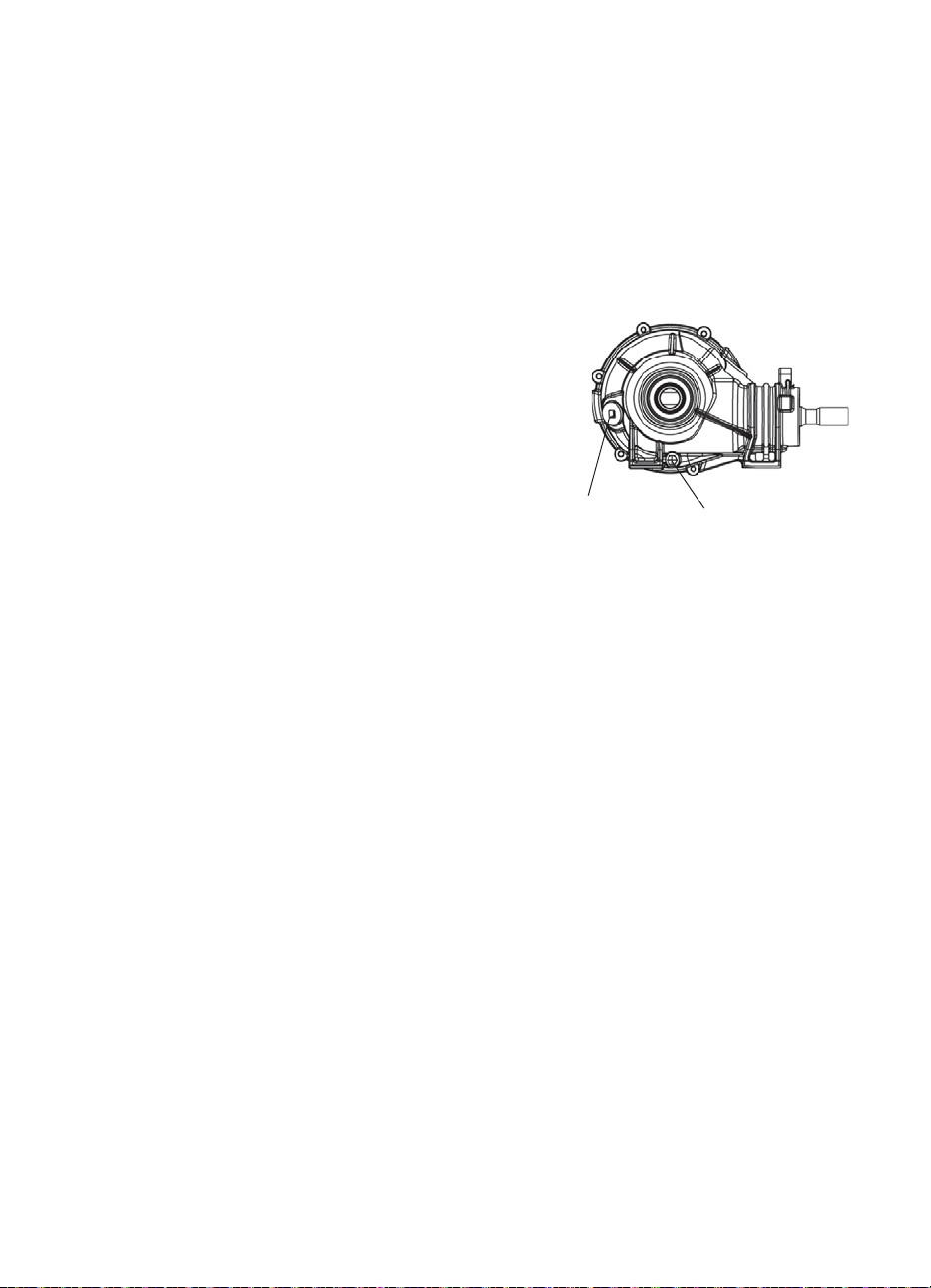
MAINTENANCE
Gearcases
Rear Gearcase (6X6)
Always check and change the rear gearcase oil at the intervals outlined in the Periodic
Maintenance Chart beginning on page 59.
Refer to the Gearcase Specifications Chart on page 65 for recommended lubricants,
capacities and torque specifications. See page 100 for the part numbers of POLARIS
products.
The rear gearcase fill plug is on the driver's side of the rear gearcase.
Oil Check
Maintain the oil level even with the bottom thread
of the fill plug hole.
1. Position the vehicle on a level surface.
2. Remove the fill plug. Check the oil level.
3. Add the recommended oil as needed.
4. Reinstall the fill plug. Torque to specification.
Oil Change
1. Remove the fill plug.
2. Place a drain pan under the drain plug.
3. Remove the drain plug. Allow the oil to drain completely.
4. Clean and reinstall the drain plug. Torque to specification.
5. Add the recommended oil.
6. Reinstall the fill plug. Torque to specification.
7. Check for leaks. Dispose of used oil properly.
Fill
Plug
Drain Plug
70
Page 73

MAINTENANCE
Spark Plugs
Spark Plug Recommendations
Refer to the specifications section beginning on page 94 for the recommended spark plug
type for your vehicle. Always torque spark plugs to specification.
NOTICE: Using non-recommended spark plugs can result in serious engine damage. Always use
Spark Plug Gap/Torque
Spark Plug Inspection
Spark plug condition is indicative of engine operation. The spark plug firing end condition
should be read after the engine is warmed up and the vehicle is driven at higher speeds.
Immediately check the spark plug for correct color.
CAUTION! A hot exhaust system and engine can cause burns. Wear protective gloves when
removing a spark plug for inspection.
1. Remove the seat. Remove the spark plug cap.
2. Using the spark plug wrench provided in the tool kit, remove the plug by rotating it
3. Reverse the procedure for spark plug installation. Torque to specification.
POLARIS-recommended spark plugs.
Model Electrode Gap New Plug Torque Used Plug Torque
All .035" (.9 mm) 18 ft. lbs.
(24 Nm)
18 ft. lbs.
(24 Nm)
counterclockwise.
Normal Plug
The normal insulator tip is gray, tan or light brown. There will be few combustion deposits.
The electrodes are not burned or eroded. This indicates the proper type and heat range for the
engine and the service.
The tip should not be white. A white insulator tip indicates overheating, caused by use of an
improper spark plug or incorrect throttle body adjustments.
Wet Fouled Plug
The wet fouled insulator tip is black. A damp oil film covers the firing end. There may be a
carbon layer over the entire nose. Generally, the electrodes are not worn. General causes of
fouling are excessive oil, use of non-recommended oil or incorrect throttle body adjustments.
71
Page 74

MAINTENANCE
Cooling System
The engine coolant level is controlled or maintained by the recovery system. The recovery
system components are the overflow bottle, radiator filler neck, radiator pressure cap and
connecting hose.
As coolant operating temperature increases, the expanding (heated) excess coolant is forced
out of the radiator, past the pressure cap, and into the overflow bottle. As engine coolant
temperature decreases, the contracting (cooled) coolant is drawn back up from the tank, past
the pressure cap, and into the radiator.
Some coolant level drop on new vehicles is normal as the system is purging itself of trapped
air. Observe coolant levels and maintain as recommended by adding coolant to the overflow
bottle.
Adding or Changing Coolant
To ensure that the coolant maintains its ability to protect the engine, we recommend that the
system be completely drained every two years and a fresh mixture of antifreeze and water
added. POLARIS recommends the use of POLARIS Antifreeze 60/40 pre mix or a 50/50
mixture of high quality aluminum compatible anti-freeze/coolant and distilled water.
POLARIS Antifreeze is already premixed and ready to use. Do not dilute with water. See
page 100 for the part numbers of POLARIS products.
Always follow the manufacturer's mixing recommendations for the freeze protection
required in your area.
Any time the cooling system has been drained for maintenance or repair , replace the coolant.
If the recovery bottle has run dry, the level in the radiator should be inspected. Add coolant
as needed.
Radiator and Cooling Fan
Always check and clean the screen and radiator fins at the intervals outlined in the Periodic
Maintenance Chart beginning on page 59. Do not obstruct or deflect air flow through the
radiator by installing unauthorized accessories in front of the radiator or behind the cooling
fan. Interference with the radiator air flow can lead to overheating and consequent engine
damage.
NOTICE: Washing the vehicle with a high-pressure hose could damage the radiator fins and impair
72
the radiator's effectiveness. Using a high-pressure system is not recommended.
Page 75

MAINTENANCE
Radiator
Cap
Overflow
Bottle
Cooling System
Overflow Bottle Coolant Level
Always check and change the coolant at the intervals outlined in the Periodic Maintenance
Chart beginning on page 59. Maintain the coolant level between the minimum and maximum
marks on the bottle (when the fluid is cool).
The overflow bottle is located in front of the right front wheel.
1. Position the vehicle on a level surface.
2. View the coolant level in the overflow bottle.
3. If the coolant level is below the safe operating
range, lift the hood and locate the overflow bottle
lid. Remove the cap and use a funnel to add
coolant through the filler opening. Reinstall the
cap.
Tip: If coolant must be added often, or if the overflow bottle
runs completely dry , there may be a leak in the system.
Have the cooling system inspected by your POLARIS
dealer.
Radiator Coolant Level
1. Lift the hood.
CAUTION! Escaping steam can cause burns. Never
remove the pressure cap while the engine is warm or hot.
Always allow the engine to cool before removing the
pressure cap.
2. Slowly remove the radiator cap.
3. View the coolant level through the opening.
4. Use a funnel and slowly add coolant as needed.
Tip: This procedure is required only if the cooling system has been drained for maintenance and/or
repair. But if the overflow bottle has run dry, the level in the radiator should also be inspected.
5. Reinstall the pressure cap. Use of a non-standard pressure cap will not allow the
recovery system to function properly. See your dealer for the correct replacement part.
73
Page 76

MAINTENANCE
WARNING
POLARIS Variable Transmission (PVT) System
Failure to comply with the instructions in this warning can result in severe injury or death.
Do not modify any component of the PVT system. Doing so may reduce its strength so that a failure
may occur at a high speed. The PVT system has been precision balanced. Any modification will cause
the system to be out of balance, creating vibration and additional loads on components.
The PVT system rotates at high speeds, creating large amounts of force on clutch components. As the
owner, you have the following responsibilities for your own safety and the safety of others:
• Always follow all recommended maintenance procedures. Always look for and remove debris inside
and around the clutch and vent system when replacing the belt.
• See your dealer as outlined in the owner's manual.
• This PVT system is intended for use on POLARIS products only. Do not install it in any other product.
• Always make sure the PVT housing is securely in place during operation.
Belt slip is responsible for creating excessive heat that destroys belts, wears clutch
components and causes outer clutch covers to fail. Switch to low range while operating at
slower speeds to extend the life of the PVT components (belt, cover, etc.).
74
Page 77

MAINTENANCE
Remove ALL Debris
POLARIS Variable Transmission (PVT) System
Belt Replacement/Debris Removal
If a belt fails, always clean any debris from the duct
and from the clutch and engine compartments when
replacing the belt.
WARNING! Failure to remove ALL debris when replacing
the belt could result in vehicle damage, loss of control and
severe injury or death.
1. Remove the seat and the underseat storage box.
2. Remove the clutch cover screws and open the
clutch cover. Remove all debris wrapped in and
around the PVT system.
3. Remove all debris from the entire clutch air duct
passage.
4. Check for signs of damage to seals on the transmission and engine. See your dealer
promptly for service if any seals appear to be damaged.
Tip: Belt slip is responsible for creating excessive heat that destroys belts, wears clutch components
and causes outer clutch covers to fail. Switch to low range while operating at slower speeds to
extend the life of the PVT components (belt, cover, etc.).
PVT Drying
There may be some instances when water is accidently ingested into the PVT system. Use
the following instructions to dry it out before operating.
1. Position the vehicle on a level surface.
2. Remove the drain plug. Allow the water to drain completely. Reinstall the drain plug.
3. Apply the brakes. Start the engine.
4. Engage the park brake.
5. Shift the transmission to neutral.
6. Apply varying throttle for 10-15 seconds to expel the moisture and air-dry the belt and
clutches. Do not hold the throttle wide open for more than 10 seconds.
7. Allow the engine RPM to settle to idle speed. Apply the service brakes. Release the park
brake and shift the transmission to the lowest available range.
8. Test for belt slippage. If the belt slips, repeat the process.
9. Take the vehicle to your dealer for service as soon as possible.
75
Page 78

MAINTENANCE
Vehicle Immersion
NOTICE: If your vehicle becomes immersed, major engine damage can result if the machine is not
If it's impossible to take your RANGER to a dealer before starting it, follow the steps outlined
below.
1. Move the vehicle to dry land or at the very least, to water below the footrests.
2. Dry any water present in the air box. Filter replacement is required if water is present.
3. Thoroughly dry the air pre-cleaner located under the hood.
4. Remove the spark plugs. Turn the engine over several times using the electric start.
5. Dry the spark plugs and reinstall, or replace with new plugs.
6. Attempt to start the engine. If necessary, repeat the drying procedure.
7. Take the vehicle to your dealer for service as soon as possible, whether you succeed in
8. If water has been ingested into the PVT follow the procedure on page 75 for drying.
Filter Systems
Air Filter
Always change the air filter at the intervals outlined in the Periodic Maintenance Chart
beginning on page 59. Service the air filter more frequently if the vehicle is operated in wet
conditions or at high throttle openings for extended periods.
1. Lift the cargo box to access the air
2. Remove the air box cover and inspect
Tip: Grasp the filter end to prevent damage to
3. Remove the air filter.
4. Do not attempt to clean the main
Tip: Apply a small amount of general purpose
5. Inspect the air box for oil or water deposits. If present, drain into a suitable container.
thoroughly inspected. Take the vehicle to your dealer before starting the engine.
starting it or not.
box.
Air Filter
the gasket. It should adhere tightly to
the cover and seal all the way around.
the filter paper.
element. Install a new air filter.
grease to the sealing edges of the filter
before installing.
76
Page 79

MAINTENANCE
WARNING
Clean-Out
Plugs
Exhaust
Outlet
Spark Arrester
Failure to heed the following warnings while servicing the spark arrester could result in serious injury or
death.
• Do not perform service on the spark arrester while the system is hot. Exhaust system temperatures
can reach 1000° F. Allo w components to cool sufficiently before proceeding.
• Remove any combustible materials from the area.
• Wear eye protection and gloves.
• Do not stand behind or in front of the vehicle while purging.
• Never run the engine in an enclosed area. Exhaust contains poisonous carbon monoxide gas that
can cause loss of consciousness or death in a very short time.
• Never operate without the spark arrestor.
• Never go under the vehicle while it's inclined.
Use the following procedure to periodically purge accumulated carbon from the exhaust
pipe.
1. Remove the arrester clean-out plugs located on the
bottom of the muffler.
2. Place the transmission in neutral.
3. Engage the park brake.
4. Start the engine.
5. Purge accumulated carbon from the system by
momentarily revving the engine several times.
6. If carbon is expelled, cover or plug the exhaust outlet
and rap on the pipe around the clean-out plugs while
revving the engine several more times.
7. If particles are still suspected to be in the muffler,
elevate the rear of the vehicle one foot higher than the front. Block the wheels.
8. Repeat steps 5 and 6 until no more particles are expelled when the engine is revved.
9. Stop the engine. Allow the arrester to cool.
10. Reinstall the arrester plugs and remove the outlet cover or plug.
77
Page 80

MAINTENANCE
WARNING
Throttle
Pedal
Boot
Adjuster
Lock Nut
Throttle System
Failure to check or maintain proper operation of the throttle system can result in an accident and lead to
serious injury or death if the throttle pedal sticks during operation.
Always check the pedal for free movement and return before starting the engine and occasionally
during operation. Never start or operate this vehicle if it has a sticking or improperly operating throttle
pedal. Immediately contact your dealer for service if throttle problems arise.
Throttle Freeplay Inspection
If the throttle pedal has excessive play due to cable stretch or
misadjustment, it will cause a delay in throttle response,
especially at low engine speed. The throttle may also not open
fully. If the throttle pedal has no freeplay, the throttle may be
hard to control, and the idle speed may be erratic.
Check the throttle pedal freeplay at the intervals outlined in the
Periodic Maintenance Chart beginning on page 59. Adjust the
freeplay if necessary.
1. Apply the brakes. Engage the park brake. Shift the
transmission to neutral.
2. Start the engine. Allow it to warm up thoroughly.
3. Measure the distance the throttle pedal moves before the engine begins to pick up speed.
Freeplay should be 1/16 to 1/8 inches (1.6-3.2 mm).
Throttle Body/Idle RPM
Idle RPM is preset by the manufacturer . If the engine idle speed is not satisfactory, please see
your POLARIS dealer for adjustment.
Throttle Freeplay Adjustment
1. Remove the seat.
2. Locate the throttle cable adjuster.
3. Squeeze the end of the rubber boot and slide it far enough to
expose the end of the inline cable adjuster.
4. Loosen the adjuster lock nut.
5. Rotate the boot to turn the adjuster until 1/16" to 1/8" (1.5-3
mm) of freeplay is achieved at the throttle pedal. See page
78.
Tip: While adjusting, lightly flip the throttle pedal up and down.
6. Tighten the lock nut.
7. Squeeze the end of the rubber boot and slide it over the cable
adjuster to its original position.
78
Page 81
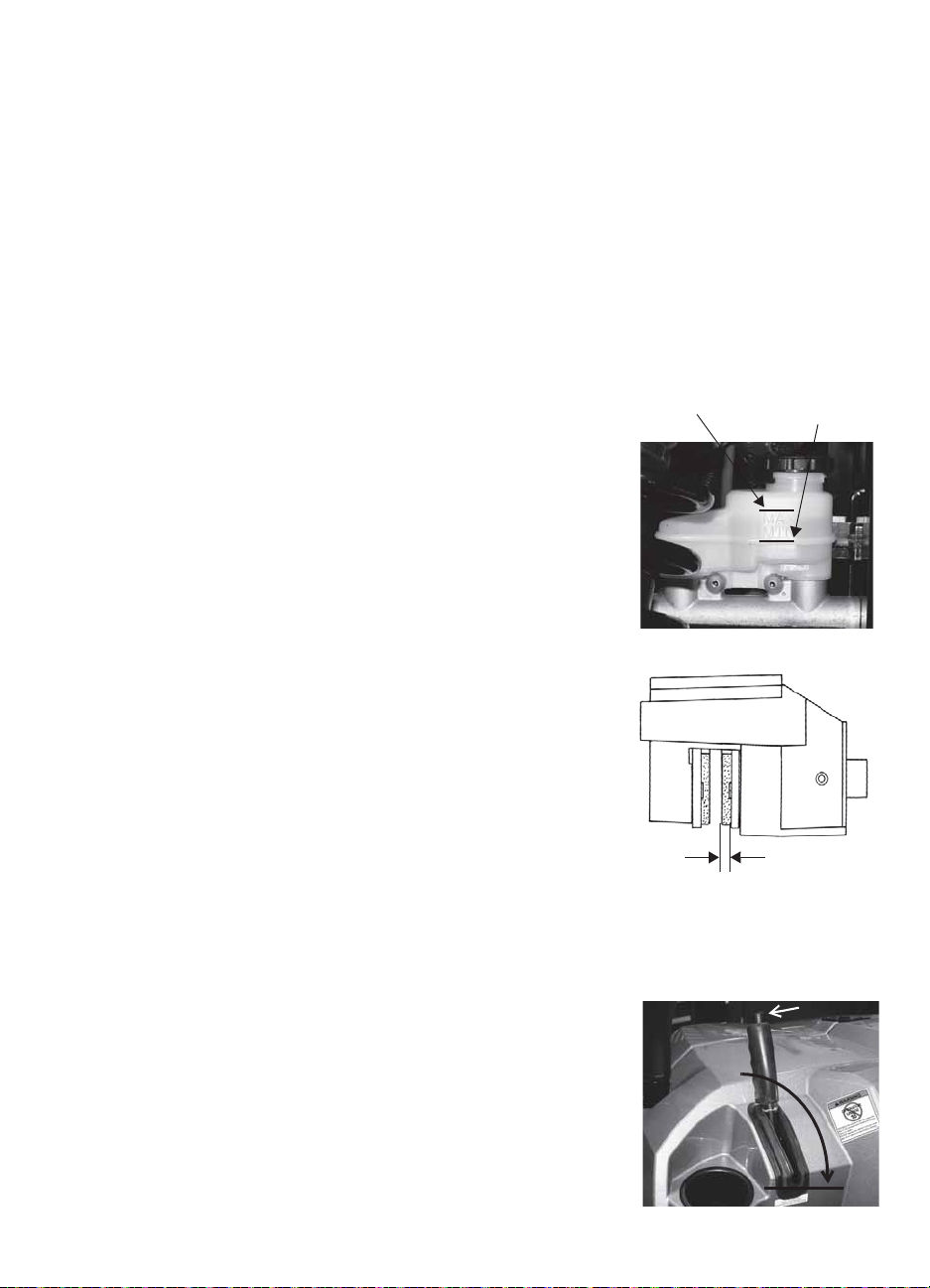
MAINTENANCE
Maximum
Minimum
Park Brake Release
Brakes
The front and rear brakes are hydraulic disc type brakes activated by the brake pedal. See
page 24.
Brake Fluid
Inspect the brake system routinely. Inspect the level of the brake fluid before each operation.
WARNING! After opening a bottle of brake fluid, always discard any unused portion. Never store or
use a partial bottle. Brake fluid is hygroscopic, meaning it rapidly absorbs moisture from the air. The
moisture causes the boiling temperature of the brake fluid to drop, which can lead to early brake fade
and the possibility of accident or severe injury.
Change the brake fluid every two years and any time the fluid becomes contaminated, the
fluid level is below the minimum, or if the type and brand of the fluid in the reservoir are
unknown.
1. Position the vehicle on a level surface.
2. V iew the brake fluid level at the reservoir in the driver’s
side wheel well.
3. The level should be between the upper (MAX) and
lower (MIN) level lines.
4. If the fluid level is lower than the upper level line, add
brake fluid to the upper (MAX) line.
5. Apply the brake forcefully for a few seconds and check
for fluid leakage around the fittings.
Brake Inspection
1. Check the brake system for fluid leaks.
2. Check the brake pedal for excessive travel or a spongy
feel.
3. Check the friction pads for wear, damage and looseness.
4. Check brake discs for signs of cracks, excessive
corrosion, warping or other damage. Clean any grease
using an approved brake cleaner or alcohol.
WARNING! Do not apply WD-40 or any petroleum product to
brake discs. These types of products are flammable and may also
reduce the friction between the brake pad and caliper.
3/64" (1mm)
5. Inspect the brake disc spline and pad wear surface for excessive wear . Change pads when
worn to 3/64" (1 mm).
Park Brake Inspection
1. Apply the brakes.
2. Pull the park brake lever downward as far as possible.
3. Check the vehicle for movement. The vehicle should
not roll while parked. If the vehicle moves, adjust the
park brake.
79
Page 82

MAINTENANCE
Outside Mounting Holes
Inside Mounting Holes
Cam
Rear Suspension Shown
Adjustment is similar for Front Suspension
Brakes
Park Brake Adjustment
Inspect and adjust park brake cable tension after the first 25 hours of operation and every 100
hours thereafter to ensure proper cable tension. Loss of tension in the park brake cable may
cause “BRAKE” to display in the rider information center, along with activation of the
limiting feature. If this occurs, move the park brake lever to the forward-most position, then
inspect and adjust park brake cable tension.
Tip: If performing this service is difficult due to conditions or location, open the hood and temporarily
disconnect the park brake connector. This will inactivate the limiting function. Reconnect the
connector as soon as possible, and adjust the park brake cable to proper tension.
1. Position the vehicle on a level surface.
2. Shift the transmission to neutral.
3. Loosen or tighten the nuts on the lever end of the park brake cable as needed.
Steering Wheel Inspection
Check the steering wheel for specified freeplay and smooth operation at the intervals
outlined in the Periodic Maintenance Chart beginning on page 59.
1. Position the vehicle on level ground.
2. Lightly turn the steering wheel left and right. There should be 0.8"-1.0" (20-25 mm) of
freeplay.
3. If there is excessive freeplay or strange noises, or the steering feels rough or "catchy,"
have the steering system inspected by an authorized POLARIS dealer.
Suspension Adjustments
The front and rear suspensions can be adjusted to provide a stiffer suspension, if necessary.
1. Remove the top shock mounting bolts from the inside mounting holes.
2. Reposition the shocks to the outside mounting holes.
3. Reinstall the shock mounting bolts. Torque to 30 ft. lbs. (40 Nm).
Spring Adjustment
Adjust the front and rear shock
absorber springs by rotating
the adjustment cam either
clockwise or counterclockwise
to increase or decrease spring
tension.
80
Page 83
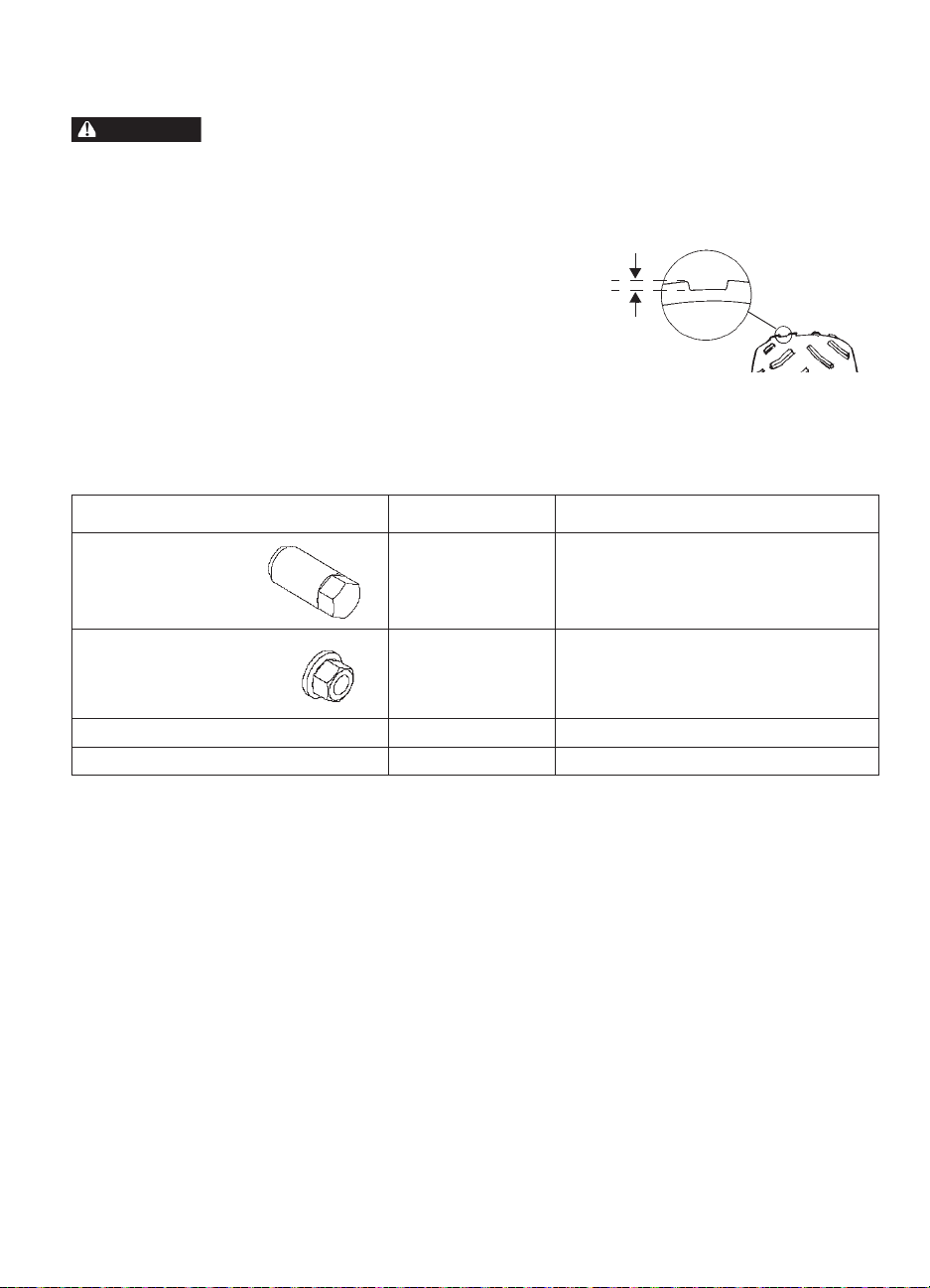
MAINTENANCE
WARNING
Tires
Operating your vehicle with worn tires, improperly inflated tires, non-standard tires or improperly
installed tires will affect vehicle handling and could cause an accident resulting in serious injury or
death. Always follow all tire maintenance procedures as outlined in this manual and on the labels on
the vehicle. Always use POLARIS-approved size and type of tires for this vehicle when replacing tires.
Tire Tread Depth
Always replace tires when tread depth is
worn to 1/8" (3 mm) or less.
Axle and Wheel Nut Torque
Specifications
Inspect the following items occasionally for tightness, and if they've been loosened for
maintenance service.
Do not lubricate the stud or the lug nut.
Nut Type Location Nut Torque
1/8" (3 mm)
Lug Nut
(Aluminum
Wheels)
Nut and Washer
(Steel Wheels)
Spindle Nut Front 70 ft. lbs. (95 Nm)
Hub Retaining Nuts Center and Rear 110 ft. lbs. (150 Nm)
Front and Rear 30 ft. lbs. (41 Nm) PLUS 1/4 TURN
Front and Rear 35 ft. lbs. (47 Nm)
81
Page 84
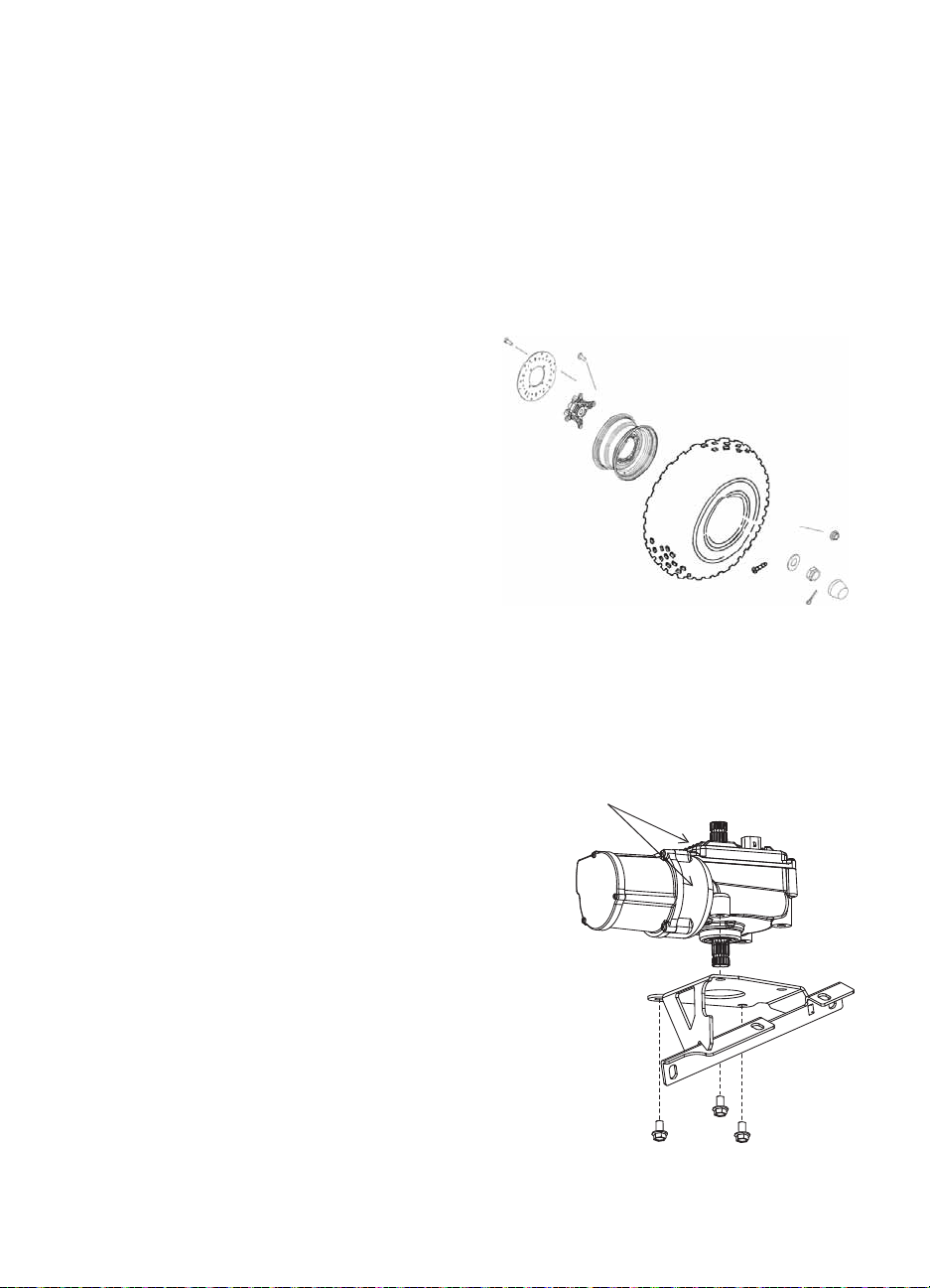
MAINTENANCE
Clean Often
Tires
Wheel Removal
1. Apply the brakes. Engage the park brake.
2. Stop the engine. Place the transmission in gear.
3. Loosen the wheel nuts slightly.
4. Elevate the side of the vehicle by placing a suitable stand under the frame.
5. Remove the wheel nuts and washers. Remove the wheel.
Wheel Installation
1. Apply the brakes.
2. Place the transmission in gear.
3. Engage the park brake.
4. Place the wheel in the correct position on the
wheel hub. Be sure the valve stem is toward
the outside and rotation arrows on the tire
point toward forward rotation.
WARNING! Improperly installed wheels can
adversely affect tire wear and vehicle handling, which
can result in serious injury or death. Always ensure
that all nuts are torqued to specification. Do not
service axle nuts that have a cotter pin installed. See
your POLARIS dealer.
5. Attach the wheel nuts and washers and finger tighten.
6. Carefully lower the vehicle to the ground.
7. Torque the wheel nuts to specification. See page 81.
Power Steering Unit
If your model is equipped with power steering,
frequently clean the areas around and on the power
steering unit to allow proper cooling. Clean these
areas thoroughly.
82
Page 85
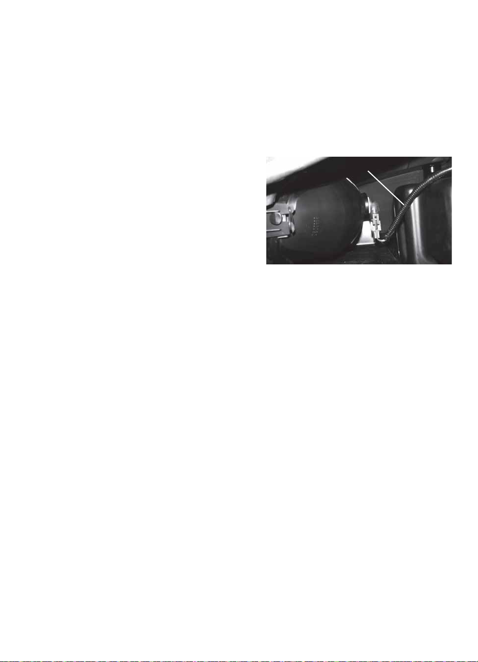
MAINTENANCE
Wiring Harness
Lights
Poor lighting can result in reduced visibility when driving. Headlight and taillight lenses
become dirty during normal operation. Clean lights frequently and replace burned out lamps
promptly . Do not operate this vehicle at night or i n low light conditions until the headlight is
replaced. Always make sure lights are adjusted properly for best visibility.
When servicing a halogen lamp, don't touch the lamp with bare fingers. Oil from your skin
leaves a residue, causing a hot spot that will shorten the life of the lamp.
Headlight Lamp Replacement
1. Open the hood.
CAUTION! Hot components can cause burns to skin.
Allow lamps to cool before servicing.
2. Unplug the headlamp from the wiring
harness. Be sure to pull on the connector, not
on the wiring.
3. Turn the lamp counterclockwise to remove
it.
4. Install the new lamp.
Tip: Make sure the tab on the lamp locates properly in the housing.
5. Reinstall the harness assembly into the headlight assembly.
Brake Lights
When the brake pedal is depressed, the brake light comes on. Check the brake light before
each ride.
1. Turn the ignition switch to the ON position.
2. Depress the brake pedal. The brake light should come on after about 10 mm (0.4 in.) of
pedal travel. If the light doesn't come on, check the bulb.
83
Page 86
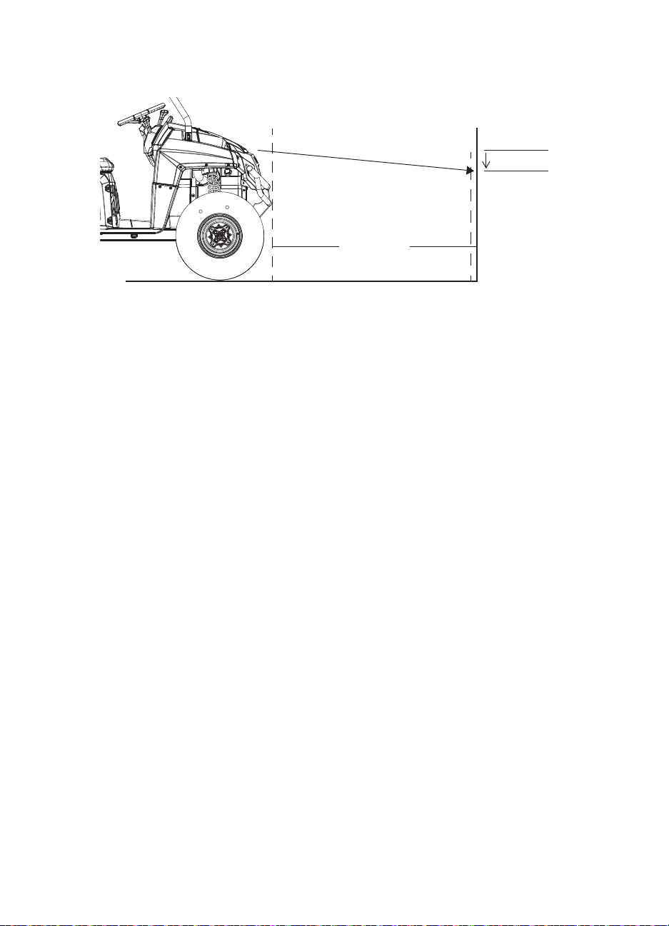
MAINTENANCE
25 ft.
(7.6 m)
8" (20 cm)
XX
Lights
Headlight Beam Adjustment
1. Place the vehicle on a level surface with the headlight approximately 25 ft. (7.6 m) from
a wall.
2. Place the transmission in gear. Engage the park brake.
3. Measure the distance from the floor to the center of the headlight and make a mark on
the wall at the same height.
4. Apply the brakes. Start the engine. Turn on the headlights.
5. Observe the headlight aim. The most intense part of the headlight beam should be aimed
8" (20 cm) below the mark placed on the wall. Include the weight of a rider on the seat
while performing this step.
6. If a headlight needs adjustment, locate the adjustment screw at the back of the headlight.
7. Loosen the screw, adjust the headlight, and tighten the screw.
8. Repeat steps 5-7 until the lamp is properly adjusted.
84
Page 87

MAINTENANCE
Fuses
If the engine stops or will not start, or if you experience other electrical failures, a fuse may
need replacement. Locate and correct any short circuits that may have caused the blown fuse,
then replace the fuse. Spare fuses are provided in the fuse box. The power steering fuse (if
equipped) is located on the power steering wiring harness near the fuse box.
If you suspect that a fuse or relay may not be working properly, please see your POLARIS
dealer.
Fuse Feature Supported
20A Accessories, 12V Power Receptacle
10A Electronic Fuel Injection
20A Engine Control Module
20A Lights
20A Main Fuse - Ignition, Instrument Cluster
30A Power Steering (if equipped)
85
Page 88

MAINTENANCE
WARNING
Lower
Mark
Upper
Mark
Battery
Battery electrolyte is poisonous. It contains sulfuric acid. Serious burns can result from contact with
skin, eyes or clothing.
Antidote:
External: Flush with water.
Internal: Drink large quantities of water or milk. Follow with milk of magnesia, beaten egg, or vegetable
oil. Call physician immediately.
Eyes: Flush with water for 15 minutes and get prompt medical attention.
Batteries produce explosive gases. Keep sparks, flame, cigarettes, etc. away. V entilate when charging
or using in an enclosed space. Always shield eyes when working near batteries. KEEP OUT OF
REACH OF CHILDREN.
Your vehicle may have either a sealed battery, which requires little maintenance, or a
conventional battery. A sealed battery can be identified by its flat covers on the top of the
battery. A conventional battery has six filler caps on the top of the battery.
Always keep battery terminals and connections free of corrosion. If cleaning is necessary,
remove the corrosion with a stiff wire brush. Wash with a solution of one tablespoon baking
soda and one cup water. Rinse well with tap water and dry off with clean shop towels. Coat
the terminals with dielectric grease or petroleum jelly. Be careful not to allow cleaning
solution or tap water into the battery.
Battery Fluid (Conventional Battery)
A poorly maintained battery will deteriorate rapidly. Check the
battery fluid level often. Maintain the fluid level between the
upper and lower level marks.
Add only distilled water. Tap water contains minerals that are
harmful to a battery.
86
Page 89
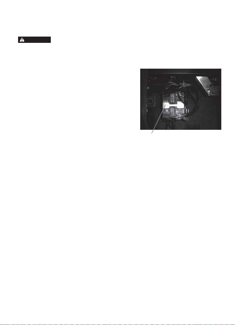
MAINTENANCE
WARNING
Battery
Battery Removal
Improperly connecting or disconnecting battery cables can result in an explosion and cause serious
injury or death. When removing the battery, always disconnect the negative (black) cable first. When
reinstalling the battery, always connect the negative (black) cable last.
1. Remove the seat. Remove the storage bin.
2. Remove the screws from the battery holddown strap and remove the strap.
3. Disconnect the black (-) battery cable first.
4. Disconnect the red (+) battery cable last.
5. Lift the battery out of the vehicle. Be
careful not to tip a conventional battery
sideways, which could spill electrolyte.
NOTICE: If electrolyte spills, immediately wash it
off with a solution of one tablespoon
baking soda and one cup water to
prevent damage to the vehicle.
Hold-Down Strap
87
Page 90

MAINTENANCE
Position T erminals
Toward Rear
Battery
Battery Installation
Using a new battery that has not been fully charged can damage the battery and result in a
shorter life. It can also hinder vehicle performance. Follow the battery charging instructions
on page 89 before installing the battery.
1. Ensure that the battery is fully charged.
2. Place the fully charged battery in the
battery holder under the driver’s seat with
the terminals toward the rear of the
vehicle.
3. Connect and tighten the red (+) cable
first. Connect and tighten the black (-)
cable last.
4. Verify that cables are properly routed and
install the hold-down strap. Tighten the
screws securely .
Battery Storage
Whenever the vehicle is not used for a period of three months or more, remove the battery
from the vehicle, ensure that it's fully charged, an d store it out of the sun in a cool, dry place.
Check battery voltage each month during storage and recharge as needed to maintain a full
charge. See page 89.
POLARIS recommends maintaining battery charge by using a POLARIS Battery Tender
charger or by charging about once a month to make up for normal self-discharge. Battery
Tender can be left connected during the storage period, and will automatically charge the
battery if the voltage drops below a pre-determined point.
88
Page 91

MAINTENANCE
Battery
Battery Charging (Conventional Battery)
1. Remove the battery from the vehicle to prevent damage from leaking or spilled
electrolyte during charging. See page 87.
2. Charge the battery with a charging output no larger than 1/10 of the battery’s amp/hr
rating. Charge as needed to raise the specific gravity to 1.270 or greater.
3. Reinstall the battery . See page 88. Make sure the positive terminal is toward the front of
the vehicle.
Battery Charging (Sealed Battery)
The following battery charging instructions apply only to the installation of a sealed battery.
Read all instructions before proceeding with the installation of this battery.
The sealed battery is already filled with electrolyte and has been sealed and fully charged at
the factory . Never pry the sealing strip off or add any other fluid to this battery.
The single most important thing about maintaining a sealed battery is to keep it fully
charged. Since the battery is sealed and the sealing strip cannot be removed, you must use a
voltmeter or multimeter to measure DC voltage.
WARNING! An overheated battery may explode, causing severe injury or death. Always watch
charging times carefully. Stop charg ing if the battery becomes very warm to the touch. Allow it to cool
before resuming charging.
For a refresh charge, follow all instructions carefully.
1. Check the battery voltage with a voltmeter or multimeter. A fully charged battery will
register 12.8 V or higher.
2. If the voltage is less than 12.8 volts, recharge the battery at 1.2 amps or less until battery
voltage is 12.8 or greater.
3. When using an automatic charger, refer to the charger manufacturer's instructions for
recharging. When using a constant current charger, use the guidelines below for
recharging.
Always verify battery condition before and 1-2 hours after the end of charging.
State of
Charge
100% 12.8-13.0 volts None, check at 3 mos. from date of
75%-100% 12.5-12.8 volts May need slight charge, if no charge
50%-75% 12.0-12.5 volts Needs charge 5-11 hours
25%-50% 11.5-12.0 volts Needs charge At least 13 hours,
0%-25% 11.5 volts or less Needs charge with desulfating charger At least 20 hours
Voltage Action
manufacture
given, check in 3 months
Charge Time
(Using constant current
charger @ standard amps
specified on top of battery)
None required
3-6 hours
verify state of charge
89
Page 92

MAINTENANCE
Cleaning and Storage
Washing the Vehicle
Keeping your POLARIS vehicle clean will not only improve its appearance but it can also
extend the life of various components.
NOTICE: High water pressure may damage components. POLARIS recommends washing the vehicle
NOTICE: Certain products, including insect repellents and chemicals, will damage plastic surfaces.
The best and safest way to clean your POLARIS vehicle is with a garden hose and a pail of
mild soap and water.
1. Use a professional-type washing cloth, cleaning the upper body first and the lower parts
2. Rinse with clean water frequently.
3. Dry surfaces with a chamois to prevent water spots.
Washing Tips
• Avoid the use of harsh cleaners, which can scratch the finish.
• Do not use a power washer to clean the vehicle.
• Do not use medium to heavy duty compounds on the finish.
• Always use clean cloths and pads for cleaning and polishing. Old or reused cloths and
pads may contain dirt particles that will scratch the finish.
• Grease all zerk fittings immediately after washing. Allow the engine to run for a while to
evaporate any water that may have entered the engine or exhaust system.
If a high pressure water system is used for cleaning (not recommended), exercise extreme
caution. The water may damage components and could remove paint and labels. Avoid
directing the water stream at the following items:
• Wheel bearings • Brakes • Switches and controls
• Radiator • Cab and body panels • Electrical components and wiring
• Transmission seals • Labels and decals
by hand or with a garden hose, using mild soap.
Do not allow these types of products to contact the vehicle.
last.
If an informational or graphic label becomes illegible or comes off, contact your POLARIS
dealer to purchase a replacement. Replacement safety labels are provided by POLARIS at no
charge.
Polishing the Vehicle
POLARIS recommends the use of common household aerosol furniture polish for polishing
the finish on your POLARIS vehicle. Follow the instructions on the container.
• Avoid the use of automotive products, some of which can scratch the finish of your
vehicle.
• Always use clean cloths and pads for cleaning and polishing. Old or reused cloths and
pads may contain dirt particles that will scratch the finish.
90
Page 93

MAINTENANCE
Cleaning and Storage
Storage Tips
NOTICE: Starting the engine during the storage period will disturb the protective film created by
Clean the Exterior
Make any necessary repairs and clean the vehicle as recommended. See page 90.
Stabilize the Fuel
1. Fill the fuel tank.
2. Add POLARIS Carbon Clean Fuel Treatment or POLARIS Fuel Stabilizer. Follow the
3. Allow the engine to run for 15-20 minutes to allow the stabilizer to disperse through the
Oil and Filter
Change the oil and filter. See page 64.
Air Filter / Air Box
1. Inspect and clean or replace the pre-cleaner and air filter. See page 76.
2. Clean the air box.
3. Drain the sediment tube.
fogging and damage could occur. Never start the engine during the storage period.
instructions on the container for the recommended amount. Carbon Clean removes water
from fuel systems, stabilizes fuel and removes carbon deposits from pistons, rings,
valves and exhaust systems.
entire fuel delivery system.
91
Page 94

MAINTENANCE
Cleaning and Storage
Storage Tips
Inspect and Lubricate
Inspect all cables and lubricate all areas of the vehicle as recommended in the Periodic
Maintenance Chart beginning on page 59.
Battery Maintenance
See page 88 for storage and charging procedures.
Fluid Levels
Inspect the fluid levels. Add or change fluids as recommended in the Periodic Maintenance
Chart beginning on page 59.
• Front gearcase fluid
• Rear and Middle gearcase fluids (6X6)
• Transmission fluid
• Brake fluid (change every two years and any time the fluid looks dark or contaminated)
• Coolant (test strength/fill)
Fog the Engine
1. Treat the fuel system with POLARIS Carbon Clean. Follow the instructions on the
container. Start the engine. Allow it to idle for several minutes so the Carbon Clean
reaches the injectors. Stop the engine.
2. Remove the spark plugs and add 2-3 tablespoons of engine oil. T o access the plug holes,
use a section of clear 1/4" hose and a small plastic squeeze bottle filled with the premeasured amount of oil. Do this carefully! If you miss the plug holes, oil will drain from
the spark plug cavities into the hole at the front of the cylinder head, and appear to be an
oil leak.
3. Reinstall the spark plugs. Torque to specification. See page 71.
4. Apply dielectric grease to the inside of each spark plug cap and reinstall the caps onto
the plugs.
5. Turn the engine over several times. Oil will be forced in and around the piston rings and
ring lands, coating the cylinder with a protective film of fresh oil.
6. If POLARIS fuel system additive is not used, fuel tank, fuel lines, and injectors should
be completely drained of gasoline.
Storage Area/Covers
Be sure the storage area is well ventilated. Cover the vehicle with a genuine POLARIS
cover. Do not use plastic or coated materials. They do not allow enough ventilation to
prevent condensation, and may promote corrosion and oxidation.
92
Page 95

MAINTENANCE
Removal from Storage
1. Check the battery electrolyte level and charge the battery if necessary. Install it in the
vehicle. Make sure the battery vent hose is routed properly and that it's not pinched or
restricted in any way.
2. Make sure the spark plug is tight.
3. Fill the fuel tank with fuel.
4. Check all the points listed in the Daily Pre-Ride Inspection section on page 35. Tightness
of the bolts, nuts and other fasteners should be checked by an authorized POLARIS
dealer.
5. Lubricate at the intervals outlined in the Periodic Maintenance Chart beginning on page
59.
Transporting the RANGER
Follow these procedures when transporting the vehicle.
1. Apply the brakes. Engage the park brake.
2. Stop the engine.
3. Place the transmission in gear.
4. Secure the fuel cap, oil cap, hood and seat. Ensure that the seats are attached correctly
and are not loose.
WARNING! Cargo and other loose vehicle parts may fly off while transporting this vehicle. Secure or
remove all cargo, and inspect the unit for loose parts prior to transport.
5. Always tie the frame of the RANGER to the transporting unit securely with suitable
straps or rope. Do not attach tie straps to the front A-arm bolt pockets.
6. Remove the key to prevent loss during transporting.
93
Page 96

SPECIFICATIONS
RANGER 800 EFI/EPS
Maximum W e ight Capacity 1500 lbs. (681 kg) (including operator, passenger, cargo, accessories)
Dry Weight 1237 lbs. (561 kg)
Test GVW - Rollover Protection
System (ROPS)
Fuel Capacity 8.8 gal. (33.3 l)
Engine Oil Capacity 1.9 qts. (1.8 l)
Coolant Capacity 3.25 qts. (3 l)
Towing Capacity 2000 lbs. (907 kg)
Hitch Tongue Capacity 150 lbs. (68 kg)
Max. Cargo Box Load* 1000 lbs. (454 kg)
Overall Length 114 in. (289.6 cm)
Overall Width (box) 60 in. (152.4 cm)
Overall Width (tires) 58 in. (147.3 cm)
Overall Height 76 in. (193 cm)
Wheelbase 76 in. (193 cm)
Cargo Box Dimensions (Inside) 36.5 x 54 x 11.5 in. (93 x 137 x 29 cm)
Ground Clearance 11.5 in. (29.2 cm)
Min. Turning Radius 158 in. (401 cm)
Engine 4 valve 4 stroke twin cylinder with counter balance
Displacement 760 cc
Bore x Stroke 80 x 76.5
Alternator Output 500 W @ 3000 RPM
Compression Ratio 10.0:1
Starting System Electric
Fuel System Electronic Fuel Injection
Ignition System Bosch EFI ECU Controlled
Spark Plug / Gap RC7YC3 /.035 in. (0.9 mm)
Front Suspension Dual A-arm w/9.6 in. (24.4 cm) of travel
Rear Suspension Independent w/9 in. (23 cm) of travel
Lubrication System Pressurized Wet Sump
1100 lbs. (499 kg) (Models sold in California)
2940 lbs. (1333.5 kg) per OSHA 29 CFR 1928.53
600 lbs. (272 kg) (Models sold in California)
94
Page 97

SPECIFICATIONS
RANGER 800 EFI/EPS
Driving System T ype PVT, 4-wheel independent shaft, lockable differential
Shift Type Single Lever (H/L/N/R)
Gear Reduction - Low 7.70:1
Gear Reduction - Reverse 7.00:1
Gear Reduction - High 3.6:1
Drive Ratio - Front: 3.818:1
Drive Ratio - Rear 3.105:1
Tire Size - Front 25 x 10 - 12 (26 x 9 - 12 for select models)
Tire Size - Rear 25 x 11 - 12 (26 x 11 - 12 for select models)
Tire Pressure - Front 10 psi (69 KPa)
Tire Pressure - Rear 12 psi (83 KPa)
Brakes, Front/Rear Foot Activated, 4 wheel hydraulic disc
Brake, Park Hand activated, mechanical
Hood Headlight 2 single beam, 50W, quartz/halogen
Taillights 10 L.E.D. (.28W)
Brake Light 10 L.E.D. (3.1W)
Clutching
See your POLARIS dealer for clutching specifications.
95
Page 98

SPECIFICATIONS
RANGER 6X6
Maximum W e ight Capacity 2000 lbs. (907 kg) (includes weight of operator, passenger, cargo, accesso-
Dry Weight 1551 lbs. (703.5 kg)
Test GVW - Rollover Protection
System (ROPS)
Fuel Capacity 8.8 gal. (33.3 l)
Engine Oil Capacity 2 qts. (1.9 l)
Coolant Capacity 3.25 qts. (3 l)
Towing Capacity 2000 lbs. (907 kg)
Max. Cargo Box Load 1250 lbs. (567 kg)
Overall Length 137 in. (348 cm)
Overall Width (box) 60 in. (152.4 cm)
Overall Width (tires) 58 in. (147.3 cm)
Overall Height 76 in. (193 cm)
Wheelbase 105 in. (267 cm)
Cargo Box Dimensions (Inside) 42.5 x 54 x 11.5 in. (108 x 137 x 29 cm)
Ground Clearance 12 in. (30.5 cm)
Min. Turning Radius 243 in. (617 cm)
Engine 4 valve 4 stroke twin cylinder with counter balance
Displacement 760 cc
Bore x Stroke 80 x 76.5
Alternator Output 500 W @ 3000 RPM
Compression Ratio 10.0:1
Starting System Electric
Fuel System Electronic Fuel Injection
Ignition System Bosch EFI ECU Controlled
Spark Plug / Gap RC7YC3 /.035 in. (0.9 mm)
Front Suspension Dual a-arm w/9.6 in. (24.4 cm) of travel
Center Suspension Independent w/9 in. (23 cm) of travel
Rear Suspension Independent w/9 in. (23 cm) of travel
Lubrication System Pressurized Wet Sump
ries)
3660 lbs. (1660 kg) per OSHA 29 CFR 1928.53
96
Page 99

RANGER 6X6
Driving System Type PVT
Shift Type Single Lever, Console (H/L/N/R)
Gear Reduction - Low 8.71:1
Gear Reduction - Reverse 7.91:1
Gear Reduction - High 3.85:1
Drive Ratio - Front: 3.818:1
Drive Ratio - Final 3.70:1
Tire Size - Front 25 x 10 - 12
Tire Size - Center/Rear 25 x 11 - 12
Tire Pressure - Front 10 psi (69 kPa)
Tire Pressure - Center/Rear 12 psi (83 kPa)
Brakes, Front/Rear Foot Activated, 4 wheel hydraulic disc
Brake, Park Hand activated, mechanical
Hood Headlight 2 single beam, 50W, quartz/halogen
Taillights 10 L.E.D. (.28W)
Brake Light 10 L.E.D. (3.1W)
Clutching
See your POLARIS dealer for clutching specifications.
SPECIFICATIONS
97
Page 100

SPECIFICATIONS
RANGER CREW 800
Maximum Weight Capacity 1750 lbs. (795 kg) (includes weight of operator, passengers, cargo, acces-
Dry Weight 1495 lbs. (678 kg)
Test GVW - Rollover Protection
System (ROPS)
Fuel Capacity 8.8 gal. (33.3 l)
Engine Oil Capacity 2 qts. (1.9 l)
Coolant Capacity 1.6 gal. (6 l)
Towing Capacity 2000 lbs. (907 kg)
Hitch Tongue Capacity 150 lbs. (68 kg)
Max. Cargo Box Load 1000 lbs. (454 kg)
Overall Length 145 in. (368 cm)
Overall Width (box) 60 in. (152.4 cm)
Overall Width (tires) 58 in. (147.3 cm)
Overall Height 76 in. (193 cm)
Wheelbase 108 in. (274 cm)
Cargo Box Dimensions (Inside) 36.5 x 54 x 11.5 in. (93 x 137 x 29 cm)
Ground Clearance 11.5 in. (29 cm)
Min. Turning Radius 255 in. (648 cm)
Engine 4 valve 4 stroke twin cylinder with counter balance
Displacement 760 cc
Bore x Stroke 80 x 76.5
Alternator Output 500 W @ 3000 RPM
Compression Ratio 10.0:1
Starting System Electric
Fuel System Electronic Fuel Injection
Ignition System Bosch EFI ECU Controlled
Spark Plug / Gap RC7YC3 /.035 in. (0.9 mm)
Front Suspension Dual a-arm w/9.6 in. (24.4 cm) of travel
Rear Suspension Independent w/9 in. (23 cm) of travel
Lubrication System Pressurized Wet Sump
sories)
3360 lbs. (1524 kg) per OSHA 29 CFR 1928.53
98
 Loading...