

Page 1

2017-2021 RANGER 500 / 570
Service Manual
FOREWORD
The information printed within this publication includes the latest product information at time of print. The most recent
version of this Service Manual is available in electronic format at www.polarisdealers.com.
This Service Manual is designed primarily for use by certified Polaris Master Service Dealer®technicians in a properly
equipped shop and should be kept available for reference. All references to left and right side of the vehicle are from
the operator's perspective when seated in a normal riding position.
Some procedures outlined in this manual require a sound knowledge of mechanical theory, tool use, and shop
procedures in order to perform the work safely and correctly. Technicians should read the text and be familiar with the
service procedures before starting any repair. Certain procedures require the use of special tools. Use only the proper
tools as specified. If you have any doubt as to your ability to perform any of the procedures outlined in this Service
Manual, contact an authorized dealer for service.
We value your input and appreciate any assistance you can provide in helping make these publications more useful.
Please provide any feedback you may have regarding this manual. Authorized dealers can submit feedback using 'Ask
Polaris'. Click on 'Ask Polaris', and then click on 'Service Manual / Service Literature Question'.
Consumers, please provide your feedback in writing to: Polaris Industries Inc. ATTN: Service Publications Department,
2100 Hwy 55, Medina, MN 55340.
Publication Printed January 2021 (PN 9850043 R01)
© Copyright 2021 Polaris Inc. All information contained within this publication is based on the latest product information at the time of publication. Due to constant
improvements in the design and quality of production components, some minor discrepancies may result between the actual vehicle and the information presented in this
publication. Depictions and/or procedures in this publication are intended for reference use only. No liability can be accepted for omissions or inaccuracies. Any reprinting
or reuse of the depictions and/or procedures contained within, whether whole or in part, is expressly prohibited. Printed in U.S.A.
Page 2
SAFETY WARNINGS
The following signal words and symbols appear throughout this manual and on the vehicle. Your safety is involved
when these words and symbols are used. Become familiar with their meanings before reading the manual.
DANGER
DANGER indicates a hazardous situation which, if not avoided, WILL result in death or serious injury.
WARNING
SAFETY ALERT WARNING indicates a hazardous situation which, if not avoided, COULD result in death or serious
SAFETY ALERT CAUTION indicates a hazardous situation which, if not avoided, COULD result in minor to moderate
NOTICE provides key information by clarifying instructions.
IMPORTANT provides key reminders during disassembly, assembly and inspection of components.
injury.
CAUTION
injury.
NOTICE
IMPORTANT
Page 3

TRADEMARKS
POLARIS ACKNOWLEDGES THE FOLLOWING PRODUCTS MENTIONED IN THIS MANUAL:
Loctite, Registered Trademark of the Loctite Corporation
Nyogel, Trademark of Wm. F. Nye Co.
Fluke, Registered Trademark of John Fluke Mfg. Co.
Mity-Vac, Registered Trademark of Neward Enterprises, Inc.
Torx, Registered Trademark of Textron
Hilliard, Trademark of the Hilliard Corporation
Warn, Trademark of Warn Industries
FOX, Registered Trademark of FOX RACING SHOX
RydeFX, Registered Trademark of ArvinMeritor
Some Polaris factory publications can be downloaded from www.polarisindustries.com, purchased from
www.purepolaris.com or by contacting the nearest Polaris dealer.
Page 4
REVISION INDEX
REV DATE
R01 01/13/2021
CHANGES
Initial release
Page 5

FEEDBACK FORM
A feedback form has been created for the technician or consumer to provide Polaris
with an overall satisfaction rating for this service manual, provide comments on your
experience or upload pictures/video. This feedback form is viewable on a mobile
device by scanning the QR code or by clicking
electronically.
HERE if viewing this document
Page 6

Page 7

2017-2021 RANGER 500 / 570
Service Manual
Chapter Summary
CHAPTER 1 : GENERAL INFORMATION
CHAPTER 2 : MAINTENANCE
CHAPTER 3 : ENGINE / COOLING SYSTEM
CHAPTER 4 : ENGINE ELECTRICAL
CHAPTER 5 : FUEL SYSTEM
CHAPTER 6 : PVT SYSTEM
CHAPTER 7 : TRANSMISSION
CHAPTER 8 : FINAL DRIVE
CHAPTER 9 : STEERING / SUSPENSION
CHAPTER 10 : BRAKE SYSTEM
CHAPTER 11 : BODY / FRAME
CHAPTER 12 : ELECTRICAL
Page 8

Page 9

GENERAL INFORMATION
CHAPTER 1
GENERAL INFORMATION
VEHICLE INFORMATION. . . .. . .. . ... . .. . .. . . .. . .. . . .. . .. . ... . .. . .. . . .. . .. . . .. . .. . . .. . .. . . .. . .. . .. . . .. . .. 1.4
MODEL NUMBER DESIGNATION (2015 +) ... . . .. . .. . . .. . .. . . . . . .. . .. . . .. . .. . . .. . .. . . . . . .. . ... . .. . . . . . 1.4
VEHICLE IDENTIFICATION NUMBER (VIN) DESIGNATION (2015+) . . . .. . .. . .. . . .. . .. . . .. . .. . . .. . .. . .. 1.4
VIN / ENGINE NUMBER LOCATION ... . .. . . .. . .. . . .. . .. . . . . . .. . .. . . .. . .. . . .. . .. . . . . . .. . . . . . .. . .. . . .. . . 1.4
REFERENCE INFORMATION . .. . . .. . .. . . .. . .. . . .. . .. . .. . . .. . .. . . .. . .. . . .. . .. . . .. . .. . . . . . .. . .. . . .. . .. . . . 1.5
REPLACEMENT KEYS . .. . . . . . .. . .. . . .. . .. . . .. . .. . . . . . .. . .. . . .. . .. . . .. . .. . . .. . .. . . . . . .. . .. . . .. . .. . . .. . 1.5
PUBLICATION PART NUMBERS .. . . .. . .. . . . . . .. . .. . . .. . .. . . . . . .. . .. . . .. . .. . . .. . .. . . .. . .. . . .. . .. . . . . . . 1.6
SPECIAL TOOLS . . .. . .. . . .. . .. . ... . .. . .. . . .. . .. . . .. . .. . ... . .. . .. . . .. . .. . . .. . .. . . .. . .. . ... . .. . .. . . .. . .. 1.8
MASTER SPECIAL TOOLS TABLE . .. . . .. . .. . ... . .. . .. . . .. . .. . . .. . .. . ... . .. . .. . . .. . .. . . .. . .. . . .. . .. . .. 1.9
MASTER TORQUE TABLE . . .. . .. . . .. . .. . . .. . .. . ... . .. . .. . . .. . .. . . .. . .. . ... . .. . ... . .. . .. . . .. . .. . . .. . .1.17
CLUTCHING CHART . .. . .. . . .. . .. . . .. . .. . ... . .. . .. . . .. . .. . . .. . .. . ... . .. . ... . .. . .. . . .. . .. . . .. . .. . ... . .1.19
GENERAL SPECIFICATIONS ... . . .. . .. . . .. . .. . . .. . .. . . . . . .. . .. . . .. . .. . . .. . .. . . .. . .. . . . . . .. . .. . . .. . .. . .1.20
2017-2018 RANGER 500 . . .. . .. . . .. . .. . . .. . .. . . . . . .. . .. . . .. . .. . . .. . .. . . . . . .. . . . . . .. . .. . . .. . .. . . .. . .. .1.20
2017-2018 RANGER 570 4X4. . ... . .. . .. . . .. . .. . . .. . .. . ... . .. . .. . . .. . .. . . .. . .. . . .. . .. . ... . .. . .. . . .. . ..1.22
2017-2018 RANGER 570 4X4 (INTL.) . . . .. . .. . . .. . .. . .. . . .. . .. . . .. . .. . . .. . .. . ... . .. . .. . . .. . .. . . .. . .. . .1.24
2017-2018 RANGER 570 4X4 TRACTOR (INTL.). .. . .. . ... . .. . .. . . .. . .. . . .. . .. . . .. . .. . .. . . .. . .. . . .. . ..1.26
2017-2018 RANGER 570 CREW ... . .. . .. . . .. . .. . . .. . .. . .. . . .. . .. . . .. . .. . ... . .. . .. . . .. . ... . .. . .. . . .. . .1.28
2019 RANGER 500. . ... . .. . .. . . .. . .. . . .. . .. . ... . .. . .. . . .. . .. . . .. . .. . ... . .. . ... . .. . .. . . .. . .. . . .. . .. . ..1.30
2019 RANGER 570 4X4 . . . . . . .. . .. . . .. . .. . . .. . .. . . . . . .. . .. . . .. . .. . . .. . .. . . .. . .. . . . . . .. . .. . . .. . .. . . .. .1.32
2019 RANGER 570 4X4 (INTL.).. . .. . . .. . .. . . .. . .. . . . . . .. . .. . . .. . .. . . .. . .. . . . . . .. . . . . . .. . .. . . .. . .. . . ..1.34
2019 RANGER 570 4X4 TRACTOR (INTL.) . . . . . .. . .. . . .. . .. . . . . . .. . .. . . .. . .. . . .. . .. . . . . . .. . ... . .. . . . .1.36
2019 RANGER 570 CREW... . . . . . .. . .. . . .. . .. . . .. . .. . . . . . .. . .. . . .. . .. . . . . . .. . . .. . .. . . . . . .. . .. . . .. . .. .1.38
2020 RANGER 500. . ... . .. . .. . . .. . .. . . .. . .. . ... . .. . .. . . .. . .. . . .. . .. . ... . .. . ... . .. . .. . . .. . .. . . .. . .. . ..1.40
2020 RANGER 570 4X4 . . . . . . .. . .. . . .. . .. . . .. . .. . . . . . .. . .. . . .. . .. . . .. . .. . . .. . .. . . . . . .. . .. . . .. . .. . . .. .1.42
2020 RANGER 570 CREW... . . . . . .. . .. . . .. . .. . . .. . .. . . . . . .. . .. . . .. . .. . . . . . .. . . .. . .. . . . . . .. . .. . . .. . .. .1.44
2021 RANGER 500. . ... . .. . .. . . .. . .. . . .. . .. . ... . .. . .. . . .. . .. . . .. . .. . ... . .. . ... . .. . .. . . .. . .. . . .. . .. . ..1.46
2021 RANGER 570 4X4 . . . . . . .. . .. . . .. . .. . . .. . .. . . . . . .. . .. . . .. . .. . . .. . .. . . .. . .. . . . . . .. . .. . . .. . .. . . .. .1.48
2021 RANGER 570 CREW... . . . . . .. . .. . . .. . .. . . .. . .. . . . . . .. . .. . . .. . .. . . . . . .. . . .. . .. . . . . . .. . .. . . .. . .. .1.50
MISC. SPECIFICATIONS AND CHARTS . . .. . .. . . .. . .. . .. . . .. . .. . . .. . .. . . .. . .. . . . . . .. . . .. . .. . .. . . .. . ..1.52
CONVERSION TABLE.. . . .. . .. . . .. . .. . ... . .. . .. . . .. . .. . . .. . .. . .. . . .. . .. . . .. . .. . . .. . .. . . .. . .. . ... . .. . .1.52
SAE TAP / DRILL SIZES . .. . ... . .. . .. . . .. . .. . . .. . .. . ... . .. . .. . . .. . .. . . .. . .. . . .. . .. . ... . .. . .. . . .. . .. . . .1.53
METRIC TAP / DRILL SIZES.. . .. . . . . . .. . .. . . .. . .. . . .. . .. . . . . . .. . .. . . .. . .. . . .. . .. . . .. . .. . . . . . .. . .. . . ..1.54
DECIMAL EQUIVALENTS ... . . .. . .. . . . . . .. . .. . . .. . .. . . .. . .. . . . . . .. . .. . . .. . .. . . .. . .. . . .. . .. . . . . . .. . .. .1.55
GENERAL DIAGNOSTICS. . .. . . .. . .. . . . . . .. . .. . . .. . .. . . . . . .. . .. . . .. . .. . . .. . .. . . .. . .. . . .. . .. . . . . . .. . .. . .1.57
GENERAL DIAGNOSTICS INFORMATION OVERVIEW .. . . . . . .. . .. . . .. . .. . . .. . .. . . . . . .. . .. . . .. . .. . . ..1.57
GUIDED SYMPTOM DIAGNOSTIC . . .. . .. . . .. . .. . . . . . .. . .. . . .. . .. . . .. . .. . . . . . .. . .. . . .. . .. . . .. . .. . . .. .1.57
GUIDED SYMPTOM REFERENCES. . . . .. . .. . . .. . .. . . .. . .. . . . . . .. . .. . . .. . .. . . .. . .. . . . . . .. . . . . . .. . .. . .1.58
ENGINE AND DRIVABILITY DIAGNOSTIC PROCEDURES .. . . .. . .. . . .. . .. . ... . .. . .. . . .. . .. . . .. . .. . ..1.59
ENGINE CRANKS BUT DOES NOT START . . .. . .. . . .. . .. . . .. . .. . . .. . .. . ... . .. . .. . . .. . .. . . .. . .. . .1.62
NO CRANK NO START OR SLOW CRANK . . .. . . .. . .. . . . . . .. . .. . . .. . .. . . .. . .. . . . . . .. . .. . . .. . .. . .1.64
OVER HEATING. . . . . .. . .. . . .. . .. . . .. . .. . . .. . .. . .. . . .. . .. . . .. . .. . . .. . .. . . .. . .. . . . . . .. . .. . . .. . .. . .1.65
1
9850043 R01 - 2017-2021 RANGER 500 / 570 Service Manual
© Copyright Polaris Inc.
1.1
Page 10

GENERAL INFORMATION
WARNING LIGHTS . . . .. . .. . . .. . .. . . .. . .. . . .. . .. . .. . . .. . .. . . .. . .. . . .. . .. . . .. . .. . .. . . .. . .. . . .. . .. . . .. . .1.66
ENGINE TROUBLESHOOTING.. . . .. . .. . ... . .. . .. . . .. . .. . . .. . .. . ... . .. . .. . . .. . .. . . .. . .. . . .. . .. . ... . ..1.67
COOLING TROUBLESHOOTING . . . .. . . . . . .. . .. . . .. . .. . . . . . .. . .. . . .. . .. . . .. . .. . . . . . .. . . .. . .. . . . . . .. . .1.69
DIGITALWRENCH .. . .. . . .. . .. . ... . .. . .. . . .. . .. . . .. . .. . .. . . .. . .. . . .. . .. . . .. . .. . . .. . .. . ... . .. . .. . . .. . .. . . ..1.70
DIGITALWRENCH® SOFTWARE OVERVIEW . .. . . .. . .. . . .. . .. . . . . . .. . .. . . .. . .. . . .. . .. . . . . . .. . .. . . .. .1.70
SPECIAL TOOLS . . .. . .. . . . . . .. . .. . . .. . .. . . .. . .. . . . . . .. . .. . . .. . .. . . .. . .. . . .. . .. . . . . . .. . .. . . .. . .. . . .. . .1.70
GUIDED DIAGNOSTICS.. . . .. . .. . ... . .. . .. . . .. . .. . . .. . .. . .. . . .. . .. . . .. . .. . . .. . .. . . .. . .. . ... . .. . .. . . ..1.70
DIGITALWRENCH® SOFTWARE INSTALLATION AND UPDATES .. . . .. . .. . . .. . .. . ... . .. . .. . . .. . .. . . .1.71
DIGITALWRENCH® COMMUNICATION ERRORS. .. . . .. . .. . . .. . .. . . . . . .. . .. . . .. . .. . . .. . .. . . . . . .. . .. .1.72
DIGITALWRENCH® - DIAGNOSTIC CONNECTOR . .. . .. . ... . .. . .. . . .. . .. . . .. . .. . . .. . .. . .. . . .. . .. . . ..1.72
DIGITALWRENCH® SERIAL NUMBER LOCATION . .. . .. . . .. . .. . ... . .. . .. . . .. . .. . . .. . .. . ... . .. . .. . . ..1.72
DIGITALWRENCH® FEATURE MAP . . .. . . .. . .. . . . . . .. . .. . . .. . .. . . .. . .. . . .. . .. . .. . . .. . .. . . .. . .. . . .. . .1.73
ENGINE CONTROLLER REPROGRAMMING (REFLASH) ... . . .. . .. . . .. . .. . .. . . .. . .. . . .. . .. . . .. . .. . ..1.74
POLARIS MOBILE DIGITAL WRENCH® (PMDW) ... . . .. . .. . . .. . .. . . .. . .. . .. . . .. . .. . . .. . .. . . .. . .. . ... . .. . ..1.74
ENGINE ELECTRICAL DIAGNOSTICS .. .. . .. . ... . .. . .. . . .. . .. . . .. . .. . ... . .. . .. . . .. . .. . . .. . .. . . .. . .. . ... . .1.75
DIAGNOSTIC TROUBLE CODES OVERVIEW .... . .. . . .. . .. . . .. . .. . . . . . .. . .. . . .. . .. . . .. . .. . . . . . .. . . . .1.75
MASTER TROUBLE CODE LIST.. . . .. . .. . . .. . .. . . . . . .. . .. . . .. . .. . . .. . .. . . .. . .. . .. . . .. . .. . . .. . .. . . .. . .1.76
CYLINDER MISFIRE DETECTION... . ... . .. . .. . . .. . .. . . .. . .. . ... . .. . .. . . .. . .. . . .. . .. . . .. . .. . ... . .. . ..1.87
FLUID LEAKS ... . . .. . .. . ... . .. . .. . . .. . .. . . .. . .. . . .. . .. . .. . . .. . .. . . .. . .. . . .. . .. . . .. . .. . .. . . .. . .. . . .. . .. . . ..1.88
FLUID INSPECTION.. . . .. . .. . . . . . .. . .. . . .. . .. . . .. . .. . . . . . .. . .. . . .. . .. . . .. . .. . . .. . .. . . . . . .. . .. . . .. . .. . . .. . .1.88
FUEL SYSTEM DIAGNOSTICS. .. . .. . . . . . .. . .. . . .. . .. . . .. . .. . . . . . .. . .. . . .. . .. . . .. . .. . . .. . .. . . . . . .. . .. . . .. .1.89
FUEL SYSTEM TROUBLESHOOTING. . . .. . .. . . . . . .. . .. . . .. . .. . . .. . .. . . . . . .. . .. . . .. . .. . . .. . .. . . .. . .. .1.89
PVT SYSTEM DIAGNOSTICS . . .. . .. . . .. . .. . . .. . .. . . . . . .. . .. . . .. . .. . . .. . .. . . . . . .. . . . . . .. . .. . . .. . .. . . .. . .. .1.91
PVT SYSTEM TROUBLESHOOTING . . . . .. . .. . . .. . .. . . .. . .. . . . . . .. . .. . . .. . .. . . .. . .. . . .. . .. . . . . . .. . .. .1.91
PVT SYSTEM OVERHEATING / DIAGNOSIS .. .. . .. . . .. . .. . . . . . .. . .. . . .. . .. . . .. . .. . . . . . .. . .. . . .. . . . . .1.93
TRANSMISSION DIAGNOSTICS . . . .. . .. . . . . . .. . .. . . .. . .. . . .. . .. . . . . . .. . .. . . .. . .. . . .. . .. . . .. . .. . . .. . .. . . . .1.94
HARD SHIFTING . .. . .. . . .. . .. . . .. . .. . ... . .. . .. . . .. . .. . . .. . .. . ... . .. . ... . .. . .. . . .. . .. . . .. . .. . ... . .. . ..1.94
TRANSMISSION ISOLATION . . .. . .. . . . . . .. . .. . . .. . .. . . .. . .. . . . . . .. . .. . . .. . .. . . .. . .. . . .. . .. . . .. . .. . . . .1.94
FINAL DRIVE DIAGNOSTICS... . . .. . .. . . .. . .. . ... . .. . .. . . .. . .. . . .. . .. . ... . .. . ... . .. . .. . . .. . .. . . .. . .. . ... . .1.95
ALL WHEEL DRIVE (AWD) CONCERNS . . . .. . .. . . .. . .. . . .. . .. . . . . . .. . .. . . .. . .. . . .. . .. . . . . . .. . . . . . .. . .1.95
DRIVESHAFT (HALF SHAFT) DIAGNOSTICS . . .. . . .. . .. . . .. . .. . ... . .. . .. . . .. . .. . . .. . .. . .. . . .. . ... . ..1.95
BRAKE SYSTEM DIAGNOSTICS. . . .. . .. . . . . . .. . .. . . .. . .. . . .. . .. . . . . . .. . .. . . .. . .. . . .. . .. . . .. . .. . . . . . .. . .. .1.96
BRAKE NOISE TROUBLESHOOTING ... . .. . .. . . .. . .. . . .. . .. . ... . .. . .. . . .. . .. . . .. . .. . .. . . .. . ... . .. . ..1.96
BRAKE VIBRATION ... . . .. . .. . ... . .. . .. . . .. . .. . . .. . .. . ... . .. . .. . . .. . .. . . .. . .. . . .. . .. . ... . .. . .. . . .. . ..1.96
CALIPER OVERHEATS (BRAKES DRAG) . .. . . . . . .. . .. . . .. . .. . . .. . .. . . . . . .. . .. . . .. . .. . . . . . .. . . .. . .. . .1.97
POOR BRAKE PERFORMANCE... . . .. . .. . . . . . .. . .. . . .. . .. . . . . . .. . . . . . .. . .. . . .. . .. . . .. . .. . . .. . .. . . . . .1.97
BRAKES LOCK.. . . .. . .. . . . . . .. . .. . . .. . .. . . .. . .. . . . . . .. . .. . . .. . .. . . .. . .. . . .. . .. . . . . . .. . .. . . .. . .. . . .. . .1.97
STEERING / SUSPENSION DIAGNOSTICS . . ... . .. . .. . . .. . .. . . .. . .. . ... . .. . .. . . .. . .. . . .. . .. . ... . .. . ... . ..1.98
EPS TROUBLESHOOTING (POWER STEERING NON-FUNCTIONAL WITH MIL ON) .. . . .. . .. . . .. . .. .1.98
EPS TROUBLESHOOTING (POWER STEERING NON-FUNCTIONAL WITH MIL OFF) . . .. . . .. . .. . . .. .1.99
EPS TROUBLESHOOTING (USING DIGITAL WRENCH®) . . .. . .. . . .. . .. . ... . .. . .. . . .. . .. . . .. . .. . ... 1.100
SHOCK ANALYSIS . . . .. . . . . . .. . .. . . .. . .. . . .. . .. . .. . . .. . .. . . .. . .. . . .. . .. . . .. . .. . . . . . .. . .. . . .. . .. . . .. 1.101
ELECTRICAL DIAGNOSTICS. . .. . .. . . .. . .. . . . . . .. . .. . . .. . .. . . .. . .. . . . . . .. . .. . . .. . . . . . .. . .. . . .. . .. . . .. . .. 1.102
ELECTRICAL SERVICE NOTES. . . . .. . .. . . .. . .. . . .. . .. . . . . . .. . .. . . .. . .. . . .. . .. . . . . . .. . . . . . .. . .. . . .. 1.102
DIGITAL MULTI-METER (DMM) NOTES .... . .. . . .. . .. . . .. . .. . .. . . .. . .. . . .. . .. . . .. . .. . .. . . .. . .. . . .. . 1.102
STATIC AND DYNAMIC TESTING .... . .. . .. . . .. . .. . . .. . .. . ... . .. . .. . . .. . .. . . .. . .. . ... . .. . . .. . .. . .. . 1.102
CONNECTOR PROBING GUIDELINES. . . . .. . .. . . .. . .. . . .. . .. . . . . . .. . .. . . .. . .. . . . . . .. . .. . . .. . . . . . .. 1.103
TESTING CONTINUITY / RESISTANCE . .. . . .. . .. . ... . .. . .. . . .. . .. . . .. . .. . . .. . .. . .. . . .. . .. . . .. . .. . . 1.104
1.2
9850043 R01 - 2017-2021 RANGER 500 / 570 Service Manual
© Copyright Polaris Inc.
Page 11

GENERAL INFORMATION
TESTING FOR A SHORT TO GROUND . . .. . . .. . .. . ... . .. . .. . . .. . .. . . .. . .. . ... . .. . .. . . .. . .. . . .. . .. . . 1.104
TESTING FOR A SHORT TO VOLTAGE .... . .. . . . . . .. . .. . . .. . .. . . .. . .. . . .. . .. . .. . . .. . .. . . .. . .. . . .. . 1.105
TESTING FOR INTERMITTENT CONDITIONS. . .. . .. . . .. . .. . .. . . .. . .. . . .. . .. . . .. . .. . .. . . .. . .. . . .. . . 1.106
TESTING CURRENT FLOW (AMPERAGE) . .. . ... . .. . .. . . .. . .. . . .. . .. . . .. . .. . .. . . .. . .. . . .. . .. . . .. . . 1.106
CURRENT DRAW - KEY OFF. .. . .. . . .. . .. . . .. . .. . ... . .. . .. . . .. . .. . . .. . .. . . .. . .. . .. . . .. . .. . . .. . .. . . . 1.107
TESTING VOLTAGE DROP. .. . .. . . .. . .. . .. . . .. . .. . . .. . .. . . .. . .. . .. . . .. . .. . . .. . .. . . .. . .. . . .. . .. . ... . 1.107
1
9850043 R01 - 2017-2021 RANGER 500 / 570 Service Manual
© Copyright Polaris Inc.
1.3
Page 12
GENERAL INFORMATION
VEHICLE INFORMATION
MODEL NUMBER DESIGNATION (2015 +)
Example: R15RUE57AC
GROUP MODEL YEAR MAKE / CHASSIS CODE ENGINE CODE REGION OPTION
1st 2nd 3rd 4th* 5th* 6th* 7th* 8th* 9th 10th**
R 1
5
R U E
5
* = digits that would transfer to 17 digit VIN and are used in digits 4-8 respectively
** = 10th digit will be used on color/featured versions of models (not including the base)
First 3 digits and 10th digit are used in model number only. They are not used with the 17 digit VIN.
Digits 1 through 8 determine Digital Wrench calibration.
VEHICLE IDENTIFICATION NUMBER (VIN) DESIGNATION (2015+)
Example: 4XARUE573FG000000
VEHICLE DESCRIPTORS VEHICLE IDENTIFIERS
7
A C
WORLD MFG. ID
CHASSIS
1 2 3 4 5 6 7 8 9 10 11 12 13 14 15 16 17
4 X A R U E 5 7 3 F G 0 0 0 0 0 0
* Model Year: A = 2010; B = 2011; C = 2012; D = 2013; E = 2014; F = 2015; G = 2016; H = 2017; J = 2018; K = 2019, L = 2020,
M = 2021
CHASSIS
DRIVELINE
MODIFIER
ENGINE SIZE
CHECK DIGIT
MODEL YEAR *
ENGINE MODIFIER
MFG. LOCATION
INDIVIDUAL SERIAL NO.
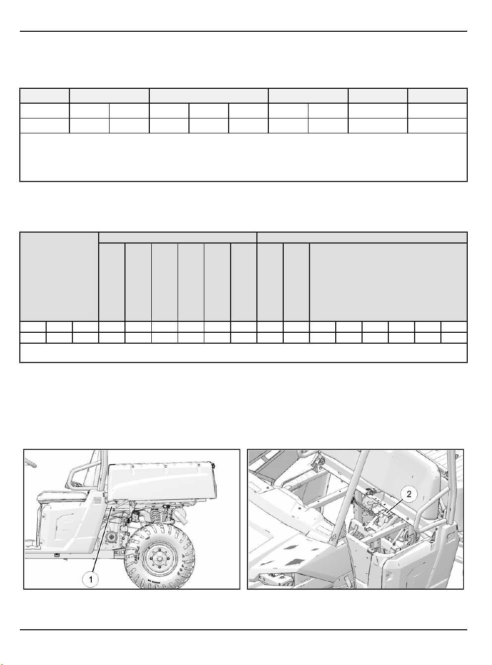
VIN / ENGINE NUMBER LOCATION
Whenever corresponding about a Polaris RANGER utility vehicle, be sure to refer to the Vehicle Identification Number
(VIN) and the engine model and serial number.
The VIN
The engine model and serial number
can be found stamped on the upper frame rail on the rear LH side of the vehicle below the cargo box.
q
can be found on a decal applied to the engine’s magneto cover.
w
1.4
9850043 R01 - 2017-2021 RANGER 500 / 570 Service Manual
© Copyright Polaris Inc.
Page 13
GENERAL INFORMATION
REFERENCE INFORMATION
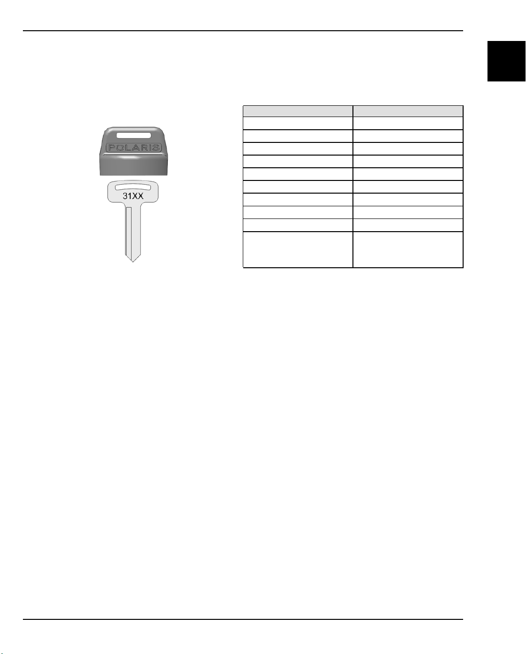
REPLACEMENT KEYS
Replacement keys can be made from the original key. To identify which series the key is, take the first two digits on the
original key and refer to the chart to the right for the proper part number.
(i.e. In this example, the first two digits are 31 which would use key blank PN 4110141.)
SERIES# PART NUMBER
20 4010278
21 4010278
22 4010321
23 4010321
27 4010321
28 4010321
31 4110141
32 4110148
67 4010278
68 4010278
1
9850043 R01 - 2017-2021 RANGER 500 / 570 Service Manual
© Copyright Polaris Inc.
1.5
Page 14

GENERAL INFORMATION
PUBLICATION PART NUMBERS
MODEL MODEL NUMBER OWNER’S MANUAL
2017 RANGER 500 2x4 R17RM250A1
2017 RANGER 500
2017 RANGER 570 / EPS
2017 RANGER 570 HD R17RMH57A4
2017 RANGER 570 CREW R17RNA57A1
2017 RANGER 570 CREW EPS
2017 RANGER 570 (Intl.)
2017 RANGER 570 EPS (Intl.)
2017 RANGER 570 Tractor (Intl.)
2017 RANGER 570 EPS Tractor (Intl.)
2018 RANGER 500 2x4 R18RM250B1
2018 RANGER 500
2018 RANGER 570 / EPS
2018 RANGER 570 HD (Intl.)
2018 RANGER 570 CREW R18RNA57B1
2018 RANGER 570 CREW EPS
2018 RANGER 570 (Intl.)
2018 RANGER 570 EPS (Intl.)
2018 RANGER 570 Tractor (Intl.)
2018 RANGER 570 EPS Tractor (Intl.)
2019 RANGER 500 2x4 R19RM250B1
2019 RANGER 500
2019 RANGER 570 / EPS
R17RMA50A1
R17RMA50A4
R17RMA57A1
R17RMA57A9
R17RME57AK
R17RNA57A9
R17RNE57AM
R17RNE57NM
R17RMA57F1
R17RMA57N1
R17RME57F1
R17RMS57F1
R17RMT57C1
R17RMT57E1
R17RMS57C1
R17RMS57CK
R17RMS57E1
R17RMS57EK
R18RMA50B1
R18RMA50B4
R18RMA57B1
R18RMA57B9
R18RME57BV
R18RME57N4
R18RNA57B9
R18RNE57BV
R18RNE57NV
R18RMA57F1
R18RMA57L1
R18RMS57F1
R18RMT57C1
R18RMT57E1
R18RMS57EV
R18RMS57C1
R18RMS57CV
R18RMS57E1
R19RMA50B1
R19RMA50B4
R19RMA57B1
R19RMA57B9
R19RME57BX
9927885
9927170
9927385
9927386
9928588
9928587
9928409
9928410
9928852
1.6
9850043 R01 - 2017-2021 RANGER 500 / 570 Service Manual
© Copyright Polaris Inc.
Page 15

MODEL MODEL NUMBER OWNER’S MANUAL
2019 RANGER 570 HD (Intl.)
2019 RANGER 570 CREW R19RNA57B1
2019 RANGER 570 CREW EPS
2019 RANGER 570 (Intl.)
2019 RANGER 570 EPS (Intl.)
2019 RANGER 570 Tractor (Intl.)
2019 RANGER 570 EPS Tractor (Intl.)
2020 RANGER 500
2020 RANGER 570 / EPS
2020 RANGER 570 HD (Intl.)
2020 RANGER 570 CREW
2020 RANGER 570 CREW EPS R20M4E57BH
2020 RANGER 570 (Intl.)
2021 RANGER 500
2021 RANGER 570 / EPS
2021 RANGER 570 HD (Intl.) R21MAE57D7
2021 RANGER 570 CREW
2021 RANGER 570 CREW EPS R21M4E57BX
2021 RANGER 570 (Intl.)
2021 RANGER 570 EPS (Intl.)
2021 RANGER 570 EPS Tractor (Intl.)
R19RME57D7
R19RNA57B9
R19RNE57BX
R19RMA57F1
R19RMA57L7
R19RMS57F1
R19RMS57E1
R19RMS57C1
R20MAA50B1
R20MAA50B7
R20MAA50J7
R20MAA57B1
R20MAA57B9
R20MAE57BH
R20MAE57D7
R20M4A57B1
R20M4A57B9
R20M4A57L1
R20MAA57K1
R21MAA50B1
R21MAA50B7
R21MAA50J7
R21MAA57B1
R21MAA57B9
R21MAE57BX
R21M4A57B1
R21M4A57B9
R21MAA57F1
R21MAA57F9
R21MAS57F1
R21MAS57F9
R21MAS57C1
R21MAS57C9
R21MAS57CK
GENERAL INFORMATION
1
9929233
9929235
9931336
9931254
9931411
9931412
When ordering service parts be sure to use the correct parts manual.
Polaris factory publications can be found at www.polaris.com or purchased from www.purepolaris.com.
9850043 R01 - 2017-2021 RANGER 500 / 570 Service Manual
© Copyright Polaris Inc.
NOTICE
1.7
Page 16

GENERAL INFORMATION
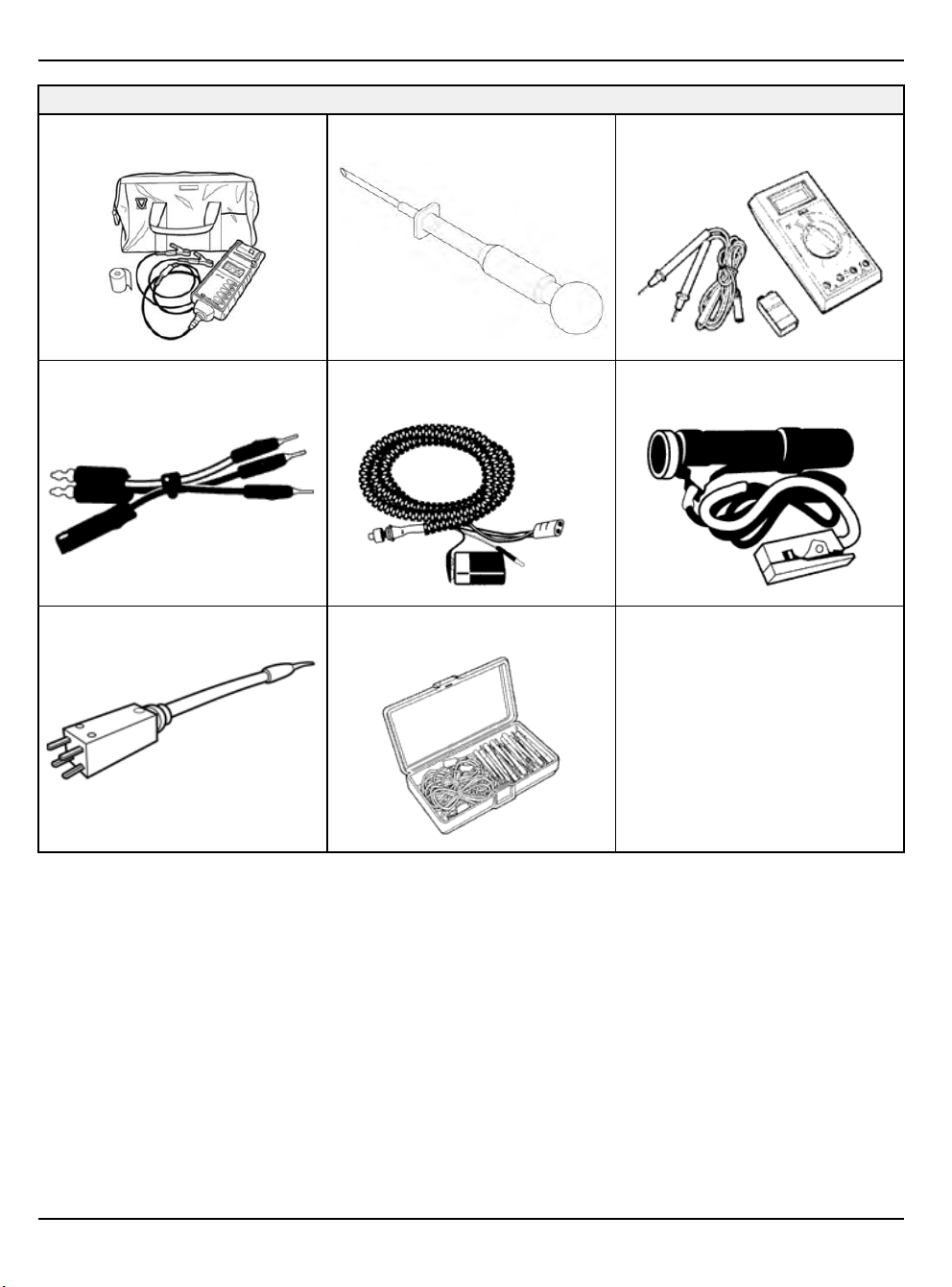
SPECIAL TOOLS
Special tools may be required while servicing this vehicle. Some of the tools listed or depicted are mandatory, while
other tools may be substituted with a similar tool, if available. Polaris recommends the use of Polaris Special Tools
when servicing any Polaris product. Dealers may order special tools through the Polaris official tool supplier.
Bosch Automotive Service Solutions 1-800-345-2233 or https://polaris.service-solutions.com
1.8
9850043 R01 - 2017-2021 RANGER 500 / 570 Service Manual
© Copyright Polaris Inc.
Page 17
MASTER SPECIAL TOOLS TABLE
ENGINE / COOLING SYSTEM
GENERAL
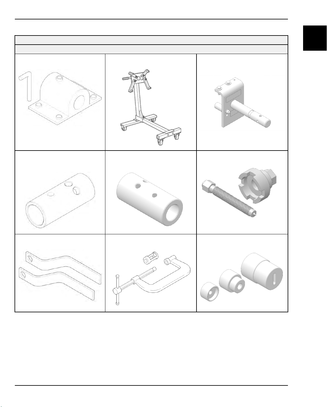
Bench Mount Engine Stand Adapter
PW-47053
Rolling Engine Stand
PU-50624
GENERAL INFORMATION
1
Engine Stand Adapter
(Mounts To The Engine)
PU-50824-A
Engine Stand Sleeve Adapter
(Use With 2” Bore Stand)
PU-50625
Stator Cover Removal Handles
PA-49317
Engine Stand Sleeve Adapter
(Use With 2.375” Bore Stand)
PW-47054
Valve Spring Compressor
PV-1253
Flywheel Puller
PA-49316
Water Pump Seal Installation Tool
PU-50869
9850043 R01 - 2017-2021 RANGER 500 / 570 Service Manual
© Copyright Polaris Inc.
1.9
Page 18
GENERAL INFORMATION
ENGINE / COOLING SYSTEM
GENERAL
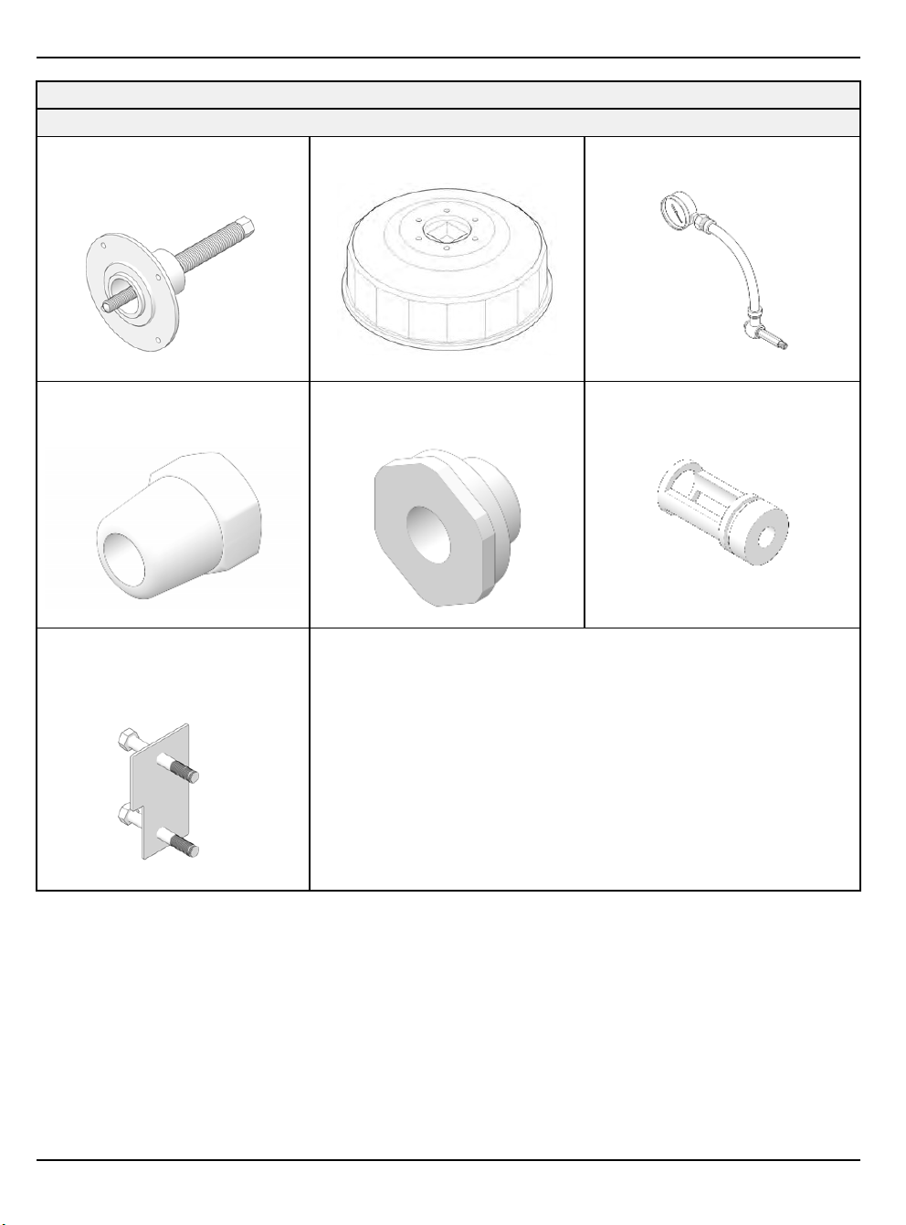
Crankshaft Removal / Installation
Tool Kit
PU-50784
Oil Filter Wrench
PU-50105
Oil Pressure Gauge
PV-43531
Oil Pressure Gauge Adapter (2017
and earlier models)
PU-50569
570 ONLY
Cylinder Holding &
Camshaft Timing Plate
PU-50563
Oil Pressure Gauge Adapter (2018
and later models)
PU-52502
Valve Spring Compressor Adapter
PV-43513-A
1.10
9850043 R01 - 2017-2021 RANGER 500 / 570 Service Manual
© Copyright Polaris Inc.
Page 19
FUEL SYSTEM
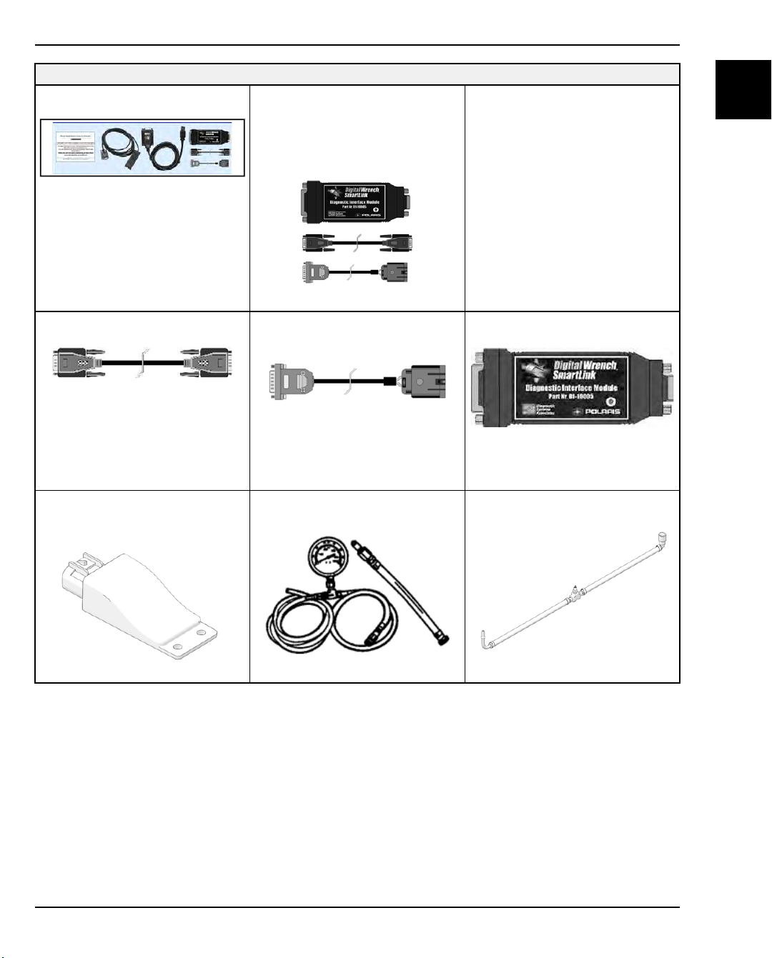
Digital Wrench Kit
PU-47063-C
Digital Wrench Smart
Link Module Kit
PU-47471
(Includes: PU-47470, PU-47469,
PU-47468)
GENERAL INFORMATION
*Serial Number Registration Card
PU-48731-A
1
*Digital Wrench® PC Interface Cable
PU-47470
Digital Wrench® Wireless
Vehicle Link
PU-51435
*Digital Wrench® Vehicle
Interface Cable
PU-47469
Fuel Pressure Gauge Kit
PU-43506-A
*Digital Wrench® SmartLink Module
PU-47468
Fuel Pressure Gauge Adapter
PV-48656
9850043 R01 - 2017-2021 RANGER 500 / 570 Service Manual
© Copyright Polaris Inc.
1.11
Page 20

GENERAL INFORMATION
FUEL SYSTEM
Fuel Pressure Gauge Adapter
PS-48762
Laptop or Desktop Computer USB/
Serial Adaptor: Saelig RS-232
Commercially Available (refer to
diagnostic software user manual or
HELP section for minimum
requirements)
Fluke 77 Digital Multi-Meter
(Fluke 77: PV-43568)
Throttle Position Sensor Tester Kit
2201519-A
(Includes: 547927, PU-47466)
1.12
9850043 R01 - 2017-2021 RANGER 500 / 570 Service Manual
© Copyright Polaris Inc.
Page 21

PVT SYSTEM
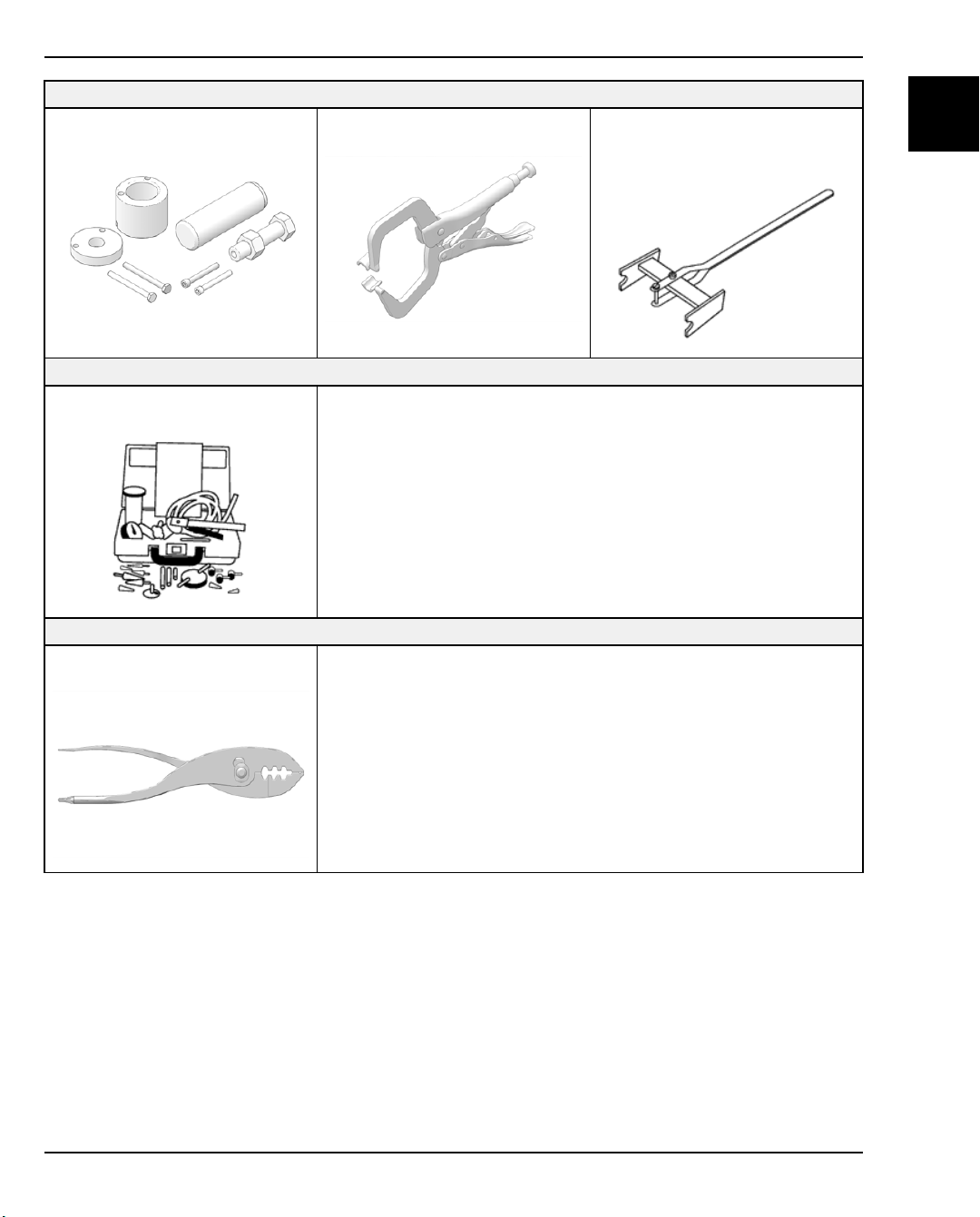
Clutch Bushing Replacement
Tool Kit
2871226
Drive Clutch Puller - Short
PA-48595
GENERAL INFORMATION
Drive Clutch Holding Tool
9314177-A
1
Drive Clutch Spider Removal
and Install Tool
2870341
Universal Clutch Compressor Tool
PU-50518-A
Piston Pin Puller
2870386
Standard Clutch Alignment Tool
2870654
Roller Pin Tool
2870910-A
Clutch Center Distance Tool
PU-50658-A
9850043 R01 - 2017-2021 RANGER 500 / 570 Service Manual
© Copyright Polaris Inc.
1.13
Page 22

GENERAL INFORMATION
TRANSMISSION
Bearing Seal Driver (50 mm)
2871282
Backlash Setting Tool
2871695 (Part of 2871702 Kit)
Rear Driveshaft Seal Guide
2871699 (Part of 2871702 Kit)
Rear Output Seal Driver
2871698 (Part of 2871702 Kit)
FINAL DRIVE
1 3/4” Straight Wrench
2870772
Roller Pin Removal Tool
2872608
Snorkel Tool
PA-50231
ADC Gearcase Piston
Installation Tool
PA-48542
Transmission Nut Socket
PU-50566
CV Boot Clamp Pliers
8700226 or PU-48951
1.14
9850043 R01 - 2017-2021 RANGER 500 / 570 Service Manual
© Copyright Polaris Inc.
Page 23
STEERING / SUSPENSION
Ball Joint Removal / Installation Tool
2870871
BRAKES
Mity Vac® Pressure Test Tool
2870975
Strut Compression Tools
2871573, 2871574
GENERAL INFORMATION
Shock Absorber Spring
Compression Tool
2870623
1
BODY / FRAME
Multi-Function Pliers
2876389
9850043 R01 - 2017-2021 RANGER 500 / 570 Service Manual
© Copyright Polaris Inc.
1.15
Page 24
GENERAL INFORMATION
ELECTRICAL
Battery Conductance Analyzer
PU-50296
Battery Hydrometer
PU-50338
Fluke® 77 Digital Multimeter
PV-43568
Hall Sensor Probe Harness
2460761
Relay Bypass
PU-49466
Static Timing Light Harness
2871745
Connector Test Kit
PV-43526
Timing Light
2870630
1.16
9850043 R01 - 2017-2021 RANGER 500 / 570 Service Manual
© Copyright Polaris Inc.
Page 25

GENERAL INFORMATION
MASTER TORQUE TABLE
ITEM
Ball Joint Nut
Ball Joint Retaining Plate
Screws
Bearing Carrier Fasteners 40 ft-lbs (54 Nm)
Body Screws (T-40) 8 ft-lbs (11 Nm)
Brake Disc Mounting Bolts
(front)
Brake Disc Mounting Bolts
(rear)
Brake Bleed Screws
Brake Caliper Mounting Bolts 46 ft-lbs (62 Nm)
Brake Line Banjo Bolts 15 ft-lbs (20 Nm)
Brake Line Flare Fittings 14 ft-lbs (19 Nm)
Brake Switch
Cam Chain Tensioner RGR
500
Cam Chain Tensioner RGR
570
Cam Chain Guide Fasteners
Camshaft Carrier Bolts
Camshaft Sprocket BoltsRGR
500
Camshaft Sprocket BoltsRGR
570
Chassis Ground Fastener
Control Arm Fasteners
(front and rear)
Coolant Bleed Screw
Coolant Temperature Sensor 17 ft-lbs (23 Nm)
CPS Retaining Bolt 9 ft-lbs (12 Nm)
Crankcase Bolts
Crankshaft Bearing Retainer
(PTO)
Cylinder Head Bolts - Black
TORQUE
30 ft-lbs (41 Nm)
8 ft-lbs (11 Nm)
18 ft-lbs (25 Nm)
27 ft-lbs (36 Nm)
47 in-lbs (5 Nm)
15 ft-lbs (20 Nm)
37 ft-lbs (50 Nm)
30 ft-lbs (40 Nm)
9 ft-lbs (12 Nm)
8 ft-lbs (10 Nm)
45 ft-lbs (60 Nm)
14 ft-lbs (19 Nm)
54 in-lbs (6 Nm)
40 ft-lbs (54 Nm)
72 in-lbs (8 Nm)
22 ft-lbs (30 Nm)
8 ft-lbs (11 Nm)
Torque in sequence for
all steps
Step 1: 21 ft-lbs (28
N·m)
Step 2: 26 ft-lbs (35
N·m)
Step 3: Additional 135°
Torque the Outer M6
Head Bolts 89 ± 9 in-lbs
(10 ± 1 Nm)
ITEM
Cylinder Head Bolts - Silver
Differential Cover Screws
Drive Clutch Retaining Bolt 45 ft-lbs (61 Nm)
Driven Clutch Retaining Bolt 38 ft-lb (52 Nm)
Drive Clutch Cover Plate
Drive Clutch Spring Retaining
Driven Clutch Retaining Bolt 38 ft-lbs (51 Nm)
Exhaust Head Pipe Bolts 18 ft-lbs (25 Nm)
Frame Bolts (front to rear)
Front Gearcase Cover Plate
Screw
Drive Clutch Spider 290 ft-lbs (393 Nm)
Ring Bolts
ETC Fasteners
ECU Mounting Screws 10 in-lbs (1 Nm)
Engine Oil Plug 12 ft-lbs (16 Nm)
Engine Oil Gallery Plug 14 ft-lbs (18 Nm)
Engine Mount (front) 40 ft-lbs (54 Nm)
Engine/Transmission
Mounting Bolts (570)
Flywheel Nut 133 ft-lbs (180 Nm)
CREW
Front Bumper / Fender
Screws
Screws
*see procedure for sequence
TORQUE
Apply light coat of
engine oil to bolt
threads and under bolt
head
Torque in sequence for
all steps
Step 1: 18 ft-lbs (25
N·m)
Step 2: 30 ft-lbs (41
N·m)
Step 3: Loosen all
fasteners until they are
unseated
Step 4: 15 ft-lbs (20
N·m)
Step 5: 26 ft-lbs (35
N·m)
Step 6: Additional 180°
Step 7: Additional 180°
Torque the Outer M6
Head Bolts 89 ± 9 in-lbs
(10 ± 1 Nm)
22 ft-lbs (30 Nm)
8 ft-lbs (10 Nm)
12 ft-lbs (16 Nm)
7 ft-lbs (10 N·m)
In Sequence:
55 ft-lb (75 Nm)
40 ft-lbs (54 Nm)
5 ft-lbs (7 Nm)
11 ft-lbs (15 Nm)
1
9850043 R01 - 2017-2021 RANGER 500 / 570 Service Manual
© Copyright Polaris Inc.
1.17
Page 26

GENERAL INFORMATION
ITEM
Front Gearcase Drain/Fill
Plugs
Front Gearcase Mounting
Bolts
Fuel Pump PFA Nut 70 ft-lbs (90 Nm)
Fuel Rail Mounting Screws 7 ft-lbs (10 Nm)
Fuel Tank Mounting Screw 17 ft-lbs (23 Nm)
Hub Castle Nut (front) 90 ft-lbs (122 Nm)
Hub Castle Nut (rear) 110 ft-lbs (150 Nm)
IAC Mount Screw
Master Cylinder Mount Bolts 17 ft-lbs (23 Nm)
Oil Pump Cover Bolt 9 ft-lbs (12 Nm)
Power Steering Bracket to
Frame Nuts
Power Steering Unit to Mount
Bracket
Prop Shaft Support Bearing
Fasteners
Prop Shaft Support Bearing
Set Screws
PVT Inner Cover Screws
(Phillips)
PVT Inner Cover Screws
(Hex)
PVT Outer Cover Screws
Seat Belt Mounting Fasteners 40 ft-lbs (54 Nm)
Shift Cable Bracket Bolts
Shock Mounting Fasteners
(rear)
Skid Plate Fasteners
Spark Plug
Spark Plug
Speed Sensor Screw 10 ft-lbs (14 Nm)
Stabilizer Bar Linkage (rear) 17 ft-lbs (23 Nm)
Stabilizer Bar Mounting
Bracket Bolts (rear)
Starter Mounting Bolts 8 ft-lbs (10 Nm)
Starter Power Wire Nut
Starter One-Way Clutch Bolts 9 ft-lbs (12 Nm)
Stator Cover Screws
Stator Mounting Bolts 9 ft-lbs (12 Nm)
Stator Wire Retainer
TORQUE
10 ft-lbs (14 Nm)
33 ft-lbs (56 Nm)
18 in-lbs (2 Nm)
15 ft-lbs (20 Nm)
30 ft-lbs (41 Nm)
36 ft-lbs (49 Nm)
35 in-lbs (4 Nm)
50 in-lbs (5 Nm)
12 ft-lbs (16 Nm)
50 in-lbs (5 Nm)
37 ft-lbs (50 Nm)
40 ft-lbs (54 Nm)
8 ft-lbs (11 Nm)
15ft-lbs (20 Nm)
Do Not Apply Anti-Seize
9ft-lbs (12 Nm)
Do Not Apply Anti-Seize
17 ft-lbs (23 Nm)
54 in-lbs (6 Nm)
9 ft-lbs (12 Nm)
6 ft-lbs (9 Nm)
ITEM
Steering Rack Mounting Bolts 16 ft-lbs (22 Nm)
Steering Shaft to EPS Unit 20 ft-lbs (27 Nm)
Steering Shaft to Steering
Rack
Steering Wheel Nut 65 ft-lbs (88 Nm)
Strut Casting Pinch Bolt 17 ft-lbs (23 Nm)
Strut Mounting Nut (top) 15 ft-lbs (21 Nm)
Thermostat Cover Bolts
Throttle Pedal Mounting Nuts 8 ft-lbs (11 Nm)
Tie Rod End to Knuckle
Tie Rod Jamb Nuts
TMAP Retaining Bolt 24 in-lbs (3 Nm)
TPS Mounting Screws 18 in-lbs (2 Nm)
Transmission Bell Crank Nut
Transmission Case Screws
Transmission Drain / Fill
Plugs
Transmission Isolator Bolt
(rear)
Transmission Rear Mount
Bracket Fasteners
Transmission Joint Bracket
Bolts
Transmission Park Flange
Screws
Transmission Sector Gear
Cover
Transmission Shift Fork
Screws
Transmission Snorkel Bearing
Retaining Plate Screws
Transmission Snorkel Tube
Locking Screw
TRS Retaining Nuts 7 ft-lbs (10 Nm)
TORQUE
46–51 ft-lbs (62-69 Nm)
8 ft-lbs (10 Nm)
40 ft-lbs (54 Nm)
14 ft-lbs (19 Nm)
15 ft-lbs (20 Nm)
18 ft-lbs (24 Nm)
14 ft-lbs (19 Nm)
40 ft-lbs (54 Nm)
17 ft-lbs (23 Nm)
ft-lbs ( Nm)
8 ft-lbs (11 Nm)
11 ft-lbs (15 Nm)
10 ft-lbs (14 Nm)
8 ft-lbs (11 Nm)
8 ft-lbs (11 Nm)
TPS Mounting Screws 18 in-lbs (2 Nm)
Valve Cover Bolts
Water Pump Impeller
Water Pump Cover Bolts
Wheel Lug Nuts (Steel
Wheels)
Wheel Lug Nuts (Aluminum
Wheels)
8 ft-lbs (10 Nm)
Finger Tight
*LH threads
9 ft-lbs (12 Nm)
(Apply Loctite® 204™ to
bolt threads)
36 ft-lbs (49 Nm)
30 ft-lbs + 90º (41 Nm + 90º)
1.18
9850043 R01 - 2017-2021 RANGER 500 / 570 Service Manual
© Copyright Polaris Inc.
Page 27
CLUTCHING CHART
RANGER 500
ALTITUDE
0-1800
Meters
(Feet)
RANGER 570
ALTITUDE
Meters
(Feet)
RANGER CREW 570
ALTITUDE
Meters
(Feet)
(0-6000)
1800-3700
(6000 - 12000)
0-1800
(0-6000)
1800-3700
(6000 - 12000)
0-1800
(0-6000)
1800-3700
(6000 - 12000)
SHIFT
WEIGHT
25–52G
(5632409)
25-48
(5633217)
SHIFT
WEIGHT
25–52G
(5632409)
25-48
(5633217)
SHIFT
WEIGHT
25-52G
(5632409)
25-48
(5633217)
GENERAL INFORMATION
1
DRIVE
SPRING
Black
(7043594)
Black
(7043594)
DRIVE
SPRING
Black
(7043594)
Black
(7043594)
DRIVE
SPRING
Black
(7043594)
Black
(7043594)
9850043 R01 - 2017-2021 RANGER 500 / 570 Service Manual
© Copyright Polaris Inc.
1.19
Page 28
GENERAL INFORMATION
GENERAL SPECIFICATIONS
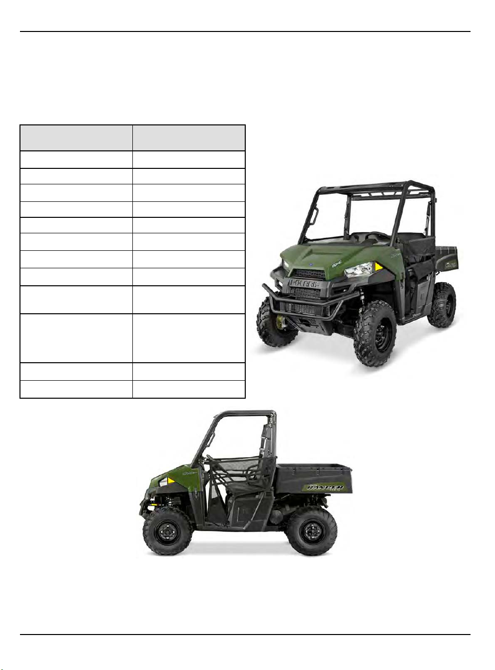
2017-2018 RANGER 500
MODEL NUMBER:
2017 2x4: R17RM250A1
2017 4x4: R17RMA50A4
2018 2x4: R18RM250B1
2018 4x4: R18RMA50B1
CATEGORY
Length
DIMENSION /
CAPACITY
110″ / 279.4 cm
Width 58″ / 147.3 cm
Height
73″ / 185 cm
Wheel Base 73″ / 185 cm
Ground Clearance 10″ / 25.4 cm
Turning Radius
150″ / 381 cm
Dry Weight 1080 lbs. / 490 kg
Cargo Box Capacity 500 lbs. / 227 kg
Cargo Box Dimensions
(inside dimensions)
L- 42″ x W-32″ x H-11.5″
(107 x 81 x 29 cm)
1000 lbs. / 454 kg
Vehicle Payload
(Includes weight of
riders, cargo and
accessories)
Towing Capacity 1500 lbs. / 680.4kg
Hitch Tongue Capacity 150 lbs. / 68 kg
1.20
9850043 R01 - 2017-2021 RANGER 500 / 570 Service Manual
© Copyright Polaris Inc.
Page 29

GENERAL INFORMATION
MODEL SPECIFICATIONS
ENGINE
Platform
Engine Displacement
Bore & Stroke 93 mm x 73.6 mm
Compression Ratio
Engine Idle Speed
Engine Max Speed 7000 RPM
Valve Clearance (Intake)
Valve Clearance (Exhaust)
Oil Requirements PS4 synthetic
Oil Capacity 2.0 qts. (1.9 l)
Coolant Capacity 120 Oz (3.5 L)
FUEL SYSTEM
Type Bosch ME17 EFI
Fuel Delivery Electronic Fuel Pump (in-
Fuel Pressure 58 ± 2 PSI (400 ± 14 kPa)
Fuel Capacity / Requirement 8.8 gal. (33.3 L) 87 Octane
ELECTRICAL
Alternator Max Output 560 W @ 3000 RPM
Headlights 2 single beam
Taillights / Brake Lights 10 LED 0.28 Watt / 3.1 Watt
Indicator Light 1.0 W
Ignition Timing ECU Controlled
Spark Plug / Gap Autolite 5923 / 0.030” - 0.037”
Battery / Amp Hr Yuasa Conventional 14 Amp
DC Outlet Standard 12 Volt
Relays EFI / Chassis / Fan / Fuel
Circuit Breaker Fan Motor: 20 Amp
Fuses Brake Light: 5 Amp
DRIVETRAIN
Transmission Type
Shift Type
Single overhead cam, 2 valve
4 stroke single cylinder.
500cc
10:1
1250 ±200 RPM
0.006 ± 0.002" (0.152 ± 0.051
mm)
0.010 ± 0.002" (0.254 ± 0.051
mm)
tank)
(minimum)
50W quartz/halogen
(0.85 +/- 0.08 mm)
Hr / 12 Volt
Pump / Headlight / EPS (EPS
model only)
EFI: 20 Amp
Fuel Pump: 10 Amp
EPS (EPS model only): 20
Amp
Accessory: 20 Amp
Drive: 10 Amp
Lights: 20 Amp
Polaris Automatic PVT
In Line Shift - P/ H / L / N / R
DRIVETRAIN
Front Gearcase Lubricant
Requirement
Transmission Lubricant
Requirement
STEERING / SUSPENSION
Toe Out 1/8 − 1/4″ (3.20 − 6.35 mm)
Front Suspension Strut / A-arm
Front Travel 9″ (20.3 cm)
Rear Suspension Independent (IRS), Dual A-
Rear Travel 10″ (22.9 cm)
Spring Adjustment Cam adjustment (rear)
WHEELS / BRAKES
Front Wheel Size / Type 12 x 8 / Steel
Rear Wheel Size / Type 12 x 9 / Steel
Front Tire Model / Size AT489 / 24 x 8 - 12
Rear Tire Model / Size AT489 / 24 x 9 - 12
Tire Air Pressure
Brake System 4 Wheel Hydraulic Disc
Brake Fluid DOT 4
Parking Brake Transmission - Park Lock
Demand Drive
6.7–7.6 oz. (200–225 ml)
Full Synthetic AGL
33.8 oz. (1000 ml)
arm, Anti-Sway Bar
Front: 10 psi (69 kPa)
Rear: 10 psi (69 kPa)
1
9850043 R01 - 2017-2021 RANGER 500 / 570 Service Manual
© Copyright Polaris Inc.
1.21
Page 30

GENERAL INFORMATION
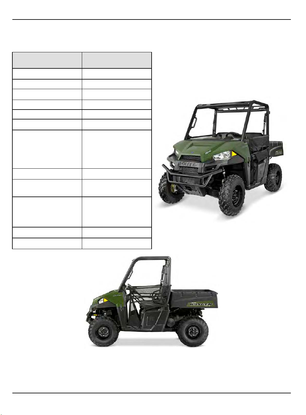
2017-2018 RANGER 570 4X4
MODEL NUMBER:
2017: R17RMA57A1/A9, R17RME57AK
2018: R18RMA57B1/B9
CATEGORY
Length
DIMENSION /
CAPACITY
110″ / 279.4 cm
Width 58″ / 147.3 cm
Height
73″ / 185 cm
Wheel Base 73″ / 185 cm
Ground Clearance 10″ / 25.4 cm
Turning Radius
150″ / 381 cm
1075 lbs. (488 kg) (570)
1100 lbs. (499 kg) (570
Dry Weight
EPS)
1140 lbs. (517 kg) (570
w/park
Cargo Box Capacity 500 lbs. / 227 kg
Cargo Box Dimensions
(inside dimensions)
L- 42″ x W-32″ x H-11.5″
(107 x 81 x 29 cm)
1000 lbs. / 454 kg
Vehicle Payload
(Includes weight of
riders, cargo and
accessories)
Towing Capacity 1500 lbs. / 680.4kg
Hitch Tongue Capacity 150 lbs. / 68 kg
1.22
9850043 R01 - 2017-2021 RANGER 500 / 570 Service Manual
© Copyright Polaris Inc.
Page 31

GENERAL INFORMATION
MODEL SPECIFICATIONS
ENGINE
Platform
Engine Displacement
Bore & Stroke 99 x 73.6 mm
Compression Ratio
Compression Pressure
Engine Idle Speed
Engine Max Speed
Valve Clearance (Intake)
Valve Clearance (Exhaust)
Oil Requirements PS4 synthetic
Oil Capacity 2 qts. (1.9 L)
Coolant Capacity 120 Oz (3.5 L)
FUEL SYSTEM
Type Bosch ME17 EFI
Fuel Delivery Electronic Fuel Pump (in-
Fuel Pressure 58 ± 2 PSI (400 ± 14 kPa)
Fuel Capacity / Requirement 8.8 gal. (33.3 L) 87 Octane
ELECTRICAL
Alternator Max Output 560 W @ 3000 RPM
Headlights 2 single beam
Taillights / Brake Lights 10 LED 0.28 Watt / 3.1 Watt
Indicator Light 1.0 Watt
Ignition Timing ECU Controlled
Spark Plug / Gap NGK MR7F / 0.0276 −
Battery / Amp Hr Yuasa Conventional 14 Amp
DC Outlet Standard 12 Volt
Relays EFI / Chassis / Fan / Fuel
Circuit Breaker Fan Motor: 20 Amp
Fuses Brake Light: 5 Amp
Domestic Single Cyl., Liquid
Cooled, 4–Stroke, DOHC
567cc
10:1
80-120 psi (compression
release)
1200 +/- 100 RPM
7750 RPM
0.005-0.007″ (0.125–0.175
mm)
0.008 ± 0.002″ (0.152–0.254
mm)
tank)
(minimum)
50W quartz/halogen
0.0315″
(0.7 – 0.9 mm)
Hr / 12 Volt
Pump / Headlight / EPS (EPS
model only)
EFI: 20 Amp
Fuel Pump: 10 Amp
EPS (EPS model only): 20
Amp
Accessory: 20 Amp
Drive: 10 Amp
Lights: 20 Amp
DRIVETRAIN
Transmission Type
Shift Type
Front Gearcase Lubricant
Requirement
Transmission Lubricant
Requirement
STEERING / SUSPENSION
Toe Out 1/8 − 1/4″
Front Suspension Strut / A-arm
Front Travel 8″ (20.3 cm)
Rear Suspension Independent (IRS)
Rear Travel 9″ (22.9 cm)
Spring Adjustment Cam adjustment (rear)
WHEELS / BRAKES
Front Wheel Size / Type 12 x 6 / Steel
Rear Wheel Size / Type 12 x 8 / Steel
Front Tire Model / Size AT489 / 25 x 8 R12
Rear Tire Model / Size AT489 / 25 x 11 R12
Tire Air Pressure
Brake System 4 Wheel Hydraulic Disc
Brake Fluid DOT 4
Parking Brake Transmission - Park Lock
Polaris Automatic PVT
In Line Shift - P/ H / L / N / R
Demand Drive
6.7–7.6 oz. (200–225 ml)
Full Synthetic AGL
33.8 oz. (1000 ml)
(3.20 − 6.35 mm)
Front: 10 psi (69 kPa)
Rear: 10 psi (69 kPa)
1
9850043 R01 - 2017-2021 RANGER 500 / 570 Service Manual
© Copyright Polaris Inc.
1.23
Page 32

GENERAL INFORMATION
2017-2018 RANGER 570 4X4 (INTL.)
MODEL NUMBER:
2017: R17RMA57N1, R17RMT57C1, R17RME57F1, R17RMS57F1
2018: R18RMS57F1
CATEGORY
Length
DIMENSION /
CAPACITY
110″ / 279.4 cm
Width 58″ / 147.3 cm
Height
73″ / 185 cm
Wheel Base 73″ / 185 cm
Ground Clearance 10″ / 25.4 cm
Turning Radius
150″ / 381 cm
1075 lbs. (488 kg) (570)
1100 lbs. (499 kg) (570
Dry Weight
EPS)
1140 lbs. (517 kg) (570
w/park)
Cargo Box Capacity 500 lbs. / 227 kg
Cargo Box Dimensions
(inside dimensions)
L- 42″ x W-32″ x H-11.5″
(107 x 81 x 29 cm)
1000 lbs. / 454 kg
Vehicle Payload
(Includes weight of
riders, cargo and
accessories)
Towing Capacity 1500 lbs. / 680.4kg
Hitch Tongue Capacity 150 lbs. / 68 kg
1.24
9850043 R01 - 2017-2021 RANGER 500 / 570 Service Manual
© Copyright Polaris Inc.
Page 33

GENERAL INFORMATION
MODEL SPECIFICATIONS
ENGINE
Platform
Engine Displacement
Bore & Stroke 99 x 73.6 mm
Compression Ratio
Compression Pressure
Engine Idle Speed
Engine Max Speed
Valve Clearance (Intake)
Valve Clearance (Exhaust)
Oil Requirements PS4 synthetic
Oil Capacity 2 qts. (1.9 L)
Coolant Capacity 120 Oz (3.5 L)
FUEL SYSTEM
Type Bosch ME17 EFI
Fuel Delivery Electronic Fuel Pump (in-
Fuel Pressure 58 ± 2 PSI (400 ± 14 kPa)
Fuel Capacity / Requirement 8.8 gal. (33.3 L) 87 Octane
ELECTRICAL
Alternator Max Output 560 W @ 3000 RPM
Headlights 2 single beam
Taillights / Brake Lights 10 LED 0.28 Watt / 3.1 Watt
Indicator Light 1.0 Watt
Ignition Timing ECU Controlled
Spark Plug / Gap NGK MR7F / 0.0276 −
Battery / Amp Hr Yuasa Conventional 14 Amp
DC Outlet Standard 12 Volt
Relays EFI / Chassis / Fan / Fuel
Circuit Breaker Fan Motor: 20 Amp
Fuses Brake Light: 5 Amp
Domestic Single Cyl., Liquid
Cooled, 4–Stroke, DOHC
567cc
10:1
80-120 psi (compression
release)
1200 +/- 100 RPM
7750 RPM
0.005-0.007″ (0.125–0.175
mm)
0.008 ± 0.002″ (0.152–0.254
mm)
tank)
(minimum)
50W quartz/halogen
0.0315″
(0.7 – 0.9 mm)
Hr / 12 Volt
Pump / Headlight / EPS (EPS
model only)
EFI: 20 Amp
Fuel Pump: 10 Amp
EPS (EPS model only): 20
Amp
Accessory: 20 Amp
Drive: 10 Amp
Lights: 20 Amp
DRIVETRAIN
Transmission Type
Shift Type
Front Gearcase Lubricant
Requirement
Transmission Lubricant
Requirement
STEERING / SUSPENSION
Toe Out 1/8 − 1/4″ (3.20 − 6.35 mm)
Front Suspension Strut / A-arm
Front Travel 8″ (20.3 cm)
Rear Suspension Independent (IRS)
Rear Travel 9″ (22.9 cm)
Spring Adjustment Cam adjustment (rear)
WHEELS / BRAKES
Front Wheel Size / Type 12 x 6 / Steel
Rear Wheel Size / Type 12 x 8 / Steel
Front Tire Model / Size AT489 / 25 x 8 R12
Rear Tire Model / Size AT489 / 25 x 11 R12
Tire Air Pressure
Brake System 4 Wheel Hydraulic Disc
Brake Fluid DOT 4
Parking Brake Transmission - Park Lock
Polaris Automatic PVT
In Line Shift - P/ H / L / N / R
Demand Drive
6.7–7.6 oz. (200–225 ml)
Full Synthetic AGL
33.8 oz. (1000 ml)
Front: 10 psi (69 kPa)
Rear: 10 psi (69 kPa)
1
9850043 R01 - 2017-2021 RANGER 500 / 570 Service Manual
© Copyright Polaris Inc.
1.25
Page 34

GENERAL INFORMATION
2017-2018 RANGER 570 4X4 TRACTOR
(INTL.)
MODEL NUMBER:
2017: R17RMT57C1, R17RMS57C1, R17RMS57CK
2018: R18RMS57C1, R18RMS57CV, R18RMT57C1
CATEGORY
Length
DIMENSION /
CAPACITY
110″ / 279.4 cm
Width 58″ / 147.3 cm
Height
73″ / 185 cm
Wheel Base 73″ / 185 cm
Ground Clearance 10″ / 25.4 cm
Turning Radius
150″ / 381 cm
1075 lbs. (488 kg) (570)
1100 lbs. (499 kg) (570
Dry Weight
EPS)
1140 lbs. (517 kg) (570
w/park)
Cargo Box Capacity 500 lbs. / 227 kg
Cargo Box Dimensions
(inside dimensions)
L- 42″ x W-32″ x H-11.5″
(107 x 81 x 29 cm)
1000 lbs. / 454 kg
Vehicle Payload
(Includes weight of
riders, cargo and
accessories)
Towing Capacity 1500 lbs. / 680.4kg
Hitch Tongue Capacity 150 lbs. / 68 kg
1.26
9850043 R01 - 2017-2021 RANGER 500 / 570 Service Manual
© Copyright Polaris Inc.
Page 35

GENERAL INFORMATION
MODEL SPECIFICATIONS
ENGINE
Platform
Engine Displacement
Bore & Stroke 99 x 73.6 mm
Compression Ratio
Compression Pressure
Engine Idle Speed
Engine Max Speed
Valve Clearance (Intake)
Valve Clearance (Exhaust)
Oil Requirements PS4 synthetic
Oil Capacity 2 qts. (1.9 L)
Coolant Capacity 120 Oz (3.5 L)
FUEL SYSTEM
Type Bosch ME17 EFI
Fuel Delivery Electronic Fuel Pump (in-
Fuel Pressure 58 ± 2 PSI (400 ± 14 kPa)
Fuel Capacity / Requirement 8.8 gal. (33.3 L) 87 Octane
ELECTRICAL
Alternator Max Output 560 W @ 3000 RPM
Headlights 2 single beam
Taillights / Brake Lights 10 LED 0.28 Watt / 3.1 Watt
Indicator Light 1.0 Watt
Ignition Timing ECU Controlled
Spark Plug / Gap NGK MR7F / 0.0276 −
Battery / Amp Hr Yuasa Conventional 14 Amp
DC Outlet Standard 12 Volt
Relays EFI / Chassis / Fan / Fuel
Circuit Breaker Fan Motor: 20 Amp
Fuses Brake Light: 5 Amp
Domestic Single Cyl., Liquid
Cooled, 4–Stroke, DOHC
567cc
10:1
80-120 psi (compression
release)
1200 +/- 100 RPM
7750 RPM
0.005-0.007″ (0.125–0.175
mm)
0.008 ± 0.002″ (0.152–0.254
mm)
tank)
(minimum)
50W quartz/halogen
0.0315″
(0.7 – 0.9 mm)
Hr / 12 Volt
Pump / Headlight / EPS (EPS
model only)
EFI: 20 Amp
Fuel Pump: 10 Amp
EPS (EPS model only): 20
Amp
Accessory: 20 Amp
Drive: 10 Amp
Lights: 20 Amp
DRIVETRAIN
Transmission Type
Shift Type
Front Gearcase Lubricant
Requirement
Transmission Lubricant
Requirement
STEERING / SUSPENSION
Toe Out 1/8 − 1/4″ (3.20 − 6.35 mm)
Front Suspension Strut / A-arm
Front Travel 8″ (20.3 cm)
Rear Suspension Independent (IRS)
Rear Travel 9″ (22.9 cm)
Spring Adjustment Cam adjustment (rear)
WHEELS / BRAKES
Front Wheel Size / Type 12 x 6 / Steel
Rear Wheel Size / Type 12 x 8 / Steel
Front Tire Model / Size AT489 / 25 x 8 R12
Rear Tire Model / Size AT489 / 25 x 11 R12
Tire Air Pressure
Brake System 4 Wheel Hydraulic Disc
Brake Fluid DOT 4
Parking Brake Transmission - Park Lock
Polaris Automatic PVT
In Line Shift - P/ H / L / N / R
Demand Drive
6.7–7.6 oz. (200–225 ml)
Full Synthetic AGL
33.8 oz. (1000 ml)
Front: 10 psi (69 kPa)
Rear: 10 psi (69 kPa)
1
9850043 R01 - 2017-2021 RANGER 500 / 570 Service Manual
© Copyright Polaris Inc.
1.27
Page 36

GENERAL INFORMATION
2017-2018 RANGER 570 CREW
MODEL NUMBER:
2017: R17RNA57A1
EPS: R17RNE57AM, R17RNE57NM, R17RNA57A9
2018: R18RNA57B1
R18RNA57B9
EPS: R18RNE57BV
R18RNE57NV
CATEGORY DIMENSION / CAPACITY
Length
Width 60″ / 152.4 cm
Height
Wheel Base 105″ / 266.7 cm
Ground Clearance 10″ / 25.4 cm
Turning Radius 237″ / 602 cm
Dry Weight 1323 lbs. / 600 kg
Cargo Box Capacity 500 lbs. / 227 kg
140″ / 355.6 cm
73″ / 185 cm
1352 lbs. / 613 kg (W /
EPS)
Cargo Box Dimensions
(inside dimensions)
L- 42″ x W-32″ x H-11.5″
(107 x 81 x 29 cm)
Vehicle Payload 1250 lbs. / 567 kg
(Includes weight of
riders, cargo and
accessories)
Towing Capacity 1500 lbs. / 680.4 kg
Hitch Tongue Capacity 150 lbs. / 68 kg
1.28
9850043 R01 - 2017-2021 RANGER 500 / 570 Service Manual
© Copyright Polaris Inc.
Page 37

GENERAL INFORMATION
MODEL SPECIFICATIONS
ENGINE
Platform
Engine Displacement
Number of Cylinders
Bore & Stroke 99 x 73.6 mm
Compression Ratio
Compression Pressure
Engine Idle Speed
Engine Max Speed
Valve Clearance (Intake)
Valve Clearance (Exhaust)
Lubrication
Oil Requirements PS4 synthetic
Oil Capacity 2 qts. (1.9 L)
Coolant Capacity 170 Oz (5 L)
FUEL SYSTEM
Type Bosch M17 EFI
Fuel Delivery Electronic Fuel Pump (in-
Fuel Pressure 58 ± 2 PSI (400 ± 14 kPa)
Fuel Capacity / Requirement 8.8 gal. (33.3 L) 87 Octane
ELECTRICAL
Alternator Max Output 560 W @ 3000 RPM
Headlights 2 single beam
Taillights / Brake Lights 10 LED 0.28 Watt / 3.1 Watt
Indicator Lamp 1.0 Watt
Ignition Timing ECU Controlled
Spark Plug / Gap NGK MR7F / 0.0276 −
Battery / Amp Hr Yuasa Conventional 14 Amp
DC Outlet Standard 12 Volt
Instrumentation Multifunction Instrument
Relays EFI / Chassis / Fan / Fuel
Domestic Single Cyl., Liquid
Cooled, 4–Stroke, DOHC
567cc
1
10:1
80-120 psi (compression
release)
1200 +/- 100 RPM
7750 RPM
0.005–0.007″ (0.125–0.175
mm)
0.008 ± 0.002″ (0.152–0.254
mm)
Pressurized Dry Sump
tank)
(minimum)
50W quartz/halogen
0.0315″
(0.7 – 0.8 mm)
Hr / 12 Volt
Cluster
Pump / Headlight / EPS (EPS
model only)
ELECTRICAL
Circuit Breaker Fan Motor: 20 Amp
Fuses Brake Light: 5 Amp
DRIVETRAIN
Transmission Type
Shift Type
Front Gearcase Lubricant
Requirement
Transmission Lubricant
Requirement
STEERING / SUSPENSION
Toe Out 1/8 − 1/4″ (3.20 − 6.35 mm)
Front Suspension Strut / A-arm
Front Travel 8″ (20.3 cm)
Rear Suspension Independent (IRS)
Rear Travel 9″ (23 cm)
Spring Adjustment Cam Adjustment (rear)
WHEELS / BRAKES
Front Wheel Size / Type 12 x 6 / Steel
Rear Wheel Size / Type 12 x 8 / Steel
Front Tire Model / Size AT489 / 25 x 8 R12
Rear Tire Model / Size AT489 / 25 x 11 R12
Tire Air Pressure Front: 10 psi
Brake System 4 Wheel Hydraulic Disc
Brake Fluid DOT 4
Parking Brake Transmission — Park Lock
EFI: 20 Amp
Fuel Pump: 10 Amp
EPS (EPS model only): 20
Amp
Accessory: 20 Amp
Drive: 10 Amp
Lights: 20 Amp
Polaris Automatic PVT
In Line Shift - P/ H / L / N / R
Demand Drive
8.97 oz. (265 ml)
Full Synthetic AGL
33.8 oz. (1000 ml)
Rear: 14 psi
1
9850043 R01 - 2017-2021 RANGER 500 / 570 Service Manual
© Copyright Polaris Inc.
1.29
Page 38

GENERAL INFORMATION
2019 RANGER 500
MODEL NUMBER:
2x4: R19RMA50B1
4x4: R19RMA50B4
CATEGORY
Length
DIMENSION /
CAPACITY
110″ / 279.4 cm
Width 58″ / 147.3 cm
Height
73″ / 185 cm
Wheel Base 73″ / 185 cm
Ground Clearance 10″ / 25.4 cm
Turning Radius
150″ / 381 cm
Dry Weight 1080 lbs. / 490 kg
Cargo Box Capacity 500 lbs. / 227 kg
Cargo Box Dimensions
(inside dimensions)
L- 42″ x W-32″ x H-11.5″
(107 x 81 x 29 cm)
1000 lbs. / 454 kg
Vehicle Payload
(Includes weight of
riders, cargo and
accessories)
Towing Capacity 1500 lbs. / 680.4kg
Hitch Tongue Capacity 150 lbs. / 68 kg
1.30
9850043 R01 - 2017-2021 RANGER 500 / 570 Service Manual
© Copyright Polaris Inc.
Page 39

GENERAL INFORMATION
MODEL SPECIFICATIONS
ENGINE
Platform
Engine Displacement
Bore & Stroke 93 mm x 73.6 mm
Compression Ratio
Engine Idle Speed
Engine Max Speed 7000 RPM
Valve Clearance (Intake)
Valve Clearance (Exhaust)
Oil Requirements PS4 synthetic
Oil Capacity 2.0 qts. (1.9 l)
Coolant Capacity 120 Oz (3.5 L)
FUEL SYSTEM
Type Bosch ME17 EFI
Fuel Delivery Electronic Fuel Pump (in-
Fuel Pressure 58 ± 2 PSI (400 ± 14 kPa)
Fuel Capacity / Requirement 8.8 gal. (33.3 L) 87 Octane
ELECTRICAL
Alternator Max Output 560 W @ 3000 RPM
Headlights 2 single beam
Taillights / Brake Lights 10 LED 0.28 Watt / 3.1 Watt
Indicator Light 1.0 W
Ignition Timing ECU Controlled
Spark Plug / Gap Autolite 5923 / 0.030” - 0.037”
Battery / Amp Hr Yuasa Conventional 14 Amp
DC Outlet Standard 12 Volt
Relays EFI / Chassis / Fan / Fuel
Circuit Breaker Fan Motor: 20 Amp
Fuses Brake Light: 5 Amp
DRIVETRAIN
Transmission Type
Shift Type
Single overhead cam, 2 valve
4 stroke single cylinder.
500cc
10:1
1250 ±200 RPM
0.006 ± 0.002" (0.152 ± 0.051
mm)
0.010 ± 0.002" (0.254 ± 0.051
mm)
tank)
(minimum)
50W quartz/halogen
(0.85 +/- 0.08 mm)
Hr / 12 Volt
Pump / Headlight / EPS (EPS
model only)
EFI: 20 Amp
Fuel Pump: 10 Amp
EPS (EPS model only): 20
Amp
Accessory: 20 Amp
Drive: 10 Amp
Lights: 20 Amp
Polaris Automatic PVT
In Line Shift - P/ H / L / N / R
DRIVETRAIN
Front Gearcase Lubricant
Requirement
Transmission Lubricant
Requirement
STEERING / SUSPENSION
Toe Out 1/8 − 1/4″ (3.20 − 6.35 mm)
Front Suspension Strut / A-arm
Front Travel 9″ (20.3 cm)
Rear Suspension Independent (IRS), Dual A-
Rear Travel 10″ (22.9 cm)
Spring Adjustment Cam adjustment (rear)
WHEELS / BRAKES
Front Wheel Size / Type 12 x 8 / Steel
Rear Wheel Size / Type 12 x 9 / Steel
Front Tire Model / Size AT489 / 24 x 8 - 12
Rear Tire Model / Size AT489 / 24 x 9 - 12
Tire Air Pressure
Brake System 4 Wheel Hydraulic Disc
Brake Fluid DOT 4
Parking Brake Transmission - Park Lock
Demand Drive
6.7–7.6 oz. (200–225 ml)
Full Synthetic AGL
33.8 oz. (1000 ml)
arm, Anti-Sway Bar
Front: 10 psi (69 kPa)
Rear: 10 psi (69 kPa)
1
9850043 R01 - 2017-2021 RANGER 500 / 570 Service Manual
© Copyright Polaris Inc.
1.31
Page 40

GENERAL INFORMATION
2019 RANGER 570 4X4
MODEL NUMBER:
R19RCA57A1, R19RCA57A4, R19RCA57B1, R19RCA57B4
CATEGORY
Length
DIMENSION /
CAPACITY
110″ / 279.4 cm
Width 58″ / 147.3 cm
Height
73″ / 185 cm
Wheel Base 73″ / 185 cm
Ground Clearance 10″ / 25.4 cm
Turning Radius
150″ / 381 cm
1075 lbs. (488 kg) (570)
1100 lbs. (499 kg) (570
Dry Weight
EPS)
1140 lbs. (517 kg) (570
w/park)
Cargo Box Capacity 500 lbs. / 227 kg
Cargo Box Dimensions
(inside dimensions)
L- 42″ x W-32″ x H-11.5″
(107 x 81 x 29 cm)
1000 lbs. / 454 kg
Vehicle Payload
(Includes weight of
riders, cargo and
accessories)
Towing Capacity 1500 lbs. / 680.4kg
Hitch Tongue Capacity 150 lbs. / 68 kg
1.32
9850043 R01 - 2017-2021 RANGER 500 / 570 Service Manual
© Copyright Polaris Inc.
Page 41

GENERAL INFORMATION
MODEL SPECIFICATIONS
ENGINE
Platform
Engine Displacement
Bore & Stroke 99 x 73.6 mm
Compression Ratio
Compression Pressure
Engine Idle Speed
Engine Max Speed
Valve Clearance (Intake)
Valve Clearance (Exhaust)
Oil Requirements PS4 synthetic
Oil Capacity 2 qts. (1.9 L)
Coolant Capacity 120 Oz (3.5 L)
FUEL SYSTEM
Type Bosch ME17 EFI
Fuel Delivery Electronic Fuel Pump (in-
Fuel Pressure 58 ± 2 PSI (400 ± 14 kPa)
Fuel Capacity / Requirement 8.8 gal. (33.3 L) 87 Octane
ELECTRICAL
Alternator Max Output 560 W @ 3000 RPM
Headlights 2 single beam
Taillights / Brake Lights 10 LED 0.28 Watt / 3.1 Watt
Indicator Light 1.0 Watt
Ignition Timing ECU Controlled
Spark Plug / Gap NGK MR7F / 0.0276 −
Battery / Amp Hr Yuasa Conventional 14 Amp
DC Outlet Standard 12 Volt
Relays EFI / Chassis / Fan / Fuel
Circuit Breaker Fan Motor: 20 Amp
Fuses Brake Light: 5 Amp
Domestic Single Cyl., Liquid
Cooled, 4–Stroke, DOHC
567cc
10:1
80-120 psi (compression
release)
1200 +/- 100 RPM
7750 RPM
0.005-0.007″ (0.125–0.175
mm)
0.008 ± 0.002″ (0.152–0.254
mm)
tank)
(minimum)
50W quartz/halogen
0.0315″
(0.7 – 0.9 mm)
Hr / 12 Volt
Pump / Headlight / EPS (EPS
model only)
EFI: 20 Amp
Fuel Pump: 10 Amp
EPS (EPS model only): 20
Amp
Accessory: 20 Amp
Drive: 10 Amp
Lights: 20 Amp
DRIVETRAIN
Transmission Type
Shift Type
Front Gearcase Lubricant
Requirement
Transmission Lubricant
Requirement
STEERING / SUSPENSION
Toe Out 1/8 − 1/4″
Front Suspension Strut / A-arm
Front Travel 8″ (20.3 cm)
Rear Suspension Independent (IRS)
Rear Travel 9″ (22.9 cm)
Spring Adjustment Cam adjustment (rear)
WHEELS / BRAKES
Front Wheel Size / Type 12 x 6 / Steel
Rear Wheel Size / Type 12 x 8 / Steel
Front Tire Model / Size AT489 / 25 x 8 R12
Rear Tire Model / Size AT489 / 25 x 11 R12
Tire Air Pressure
Brake System 4 Wheel Hydraulic Disc
Brake Fluid DOT 4
Parking Brake Transmission - Park Lock
Polaris Automatic PVT
In Line Shift - P/ H / L / N / R
Demand Drive
6.7–7.6 oz. (200–225 ml)
Full Synthetic AGL
33.8 oz. (1000 ml)
(3.20 − 6.35 mm)
Front: 10 psi (69 kPa)
Rear: 10 psi (69 kPa)
1
9850043 R01 - 2017-2021 RANGER 500 / 570 Service Manual
© Copyright Polaris Inc.
1.33
Page 42

GENERAL INFORMATION
2019 RANGER 570 4X4 (INTL.)
MODEL NUMBER:
R19RMA57F1
CATEGORY
Length
DIMENSION /
CAPACITY
110″ / 279.4 cm
Width 58″ / 147.3 cm
Height
73″ / 185 cm
Wheel Base 73″ / 185 cm
Ground Clearance 10″ / 25.4 cm
Turning Radius
150″ / 381 cm
1075 lbs. (488 kg) (570)
1100 lbs. (499 kg) (570
Dry Weight
EPS)
1140 lbs. (517 kg) (570
w/park
Cargo Box Capacity 500 lbs. / 227 kg
Cargo Box Dimensions
(inside dimensions)
L- 42″ x W-32″ x H-11.5″
(107 x 81 x 29 cm)
1000 lbs. / 454 kg
Vehicle Payload
(Includes weight of
riders, cargo and
accessories)
Towing Capacity 1500 lbs. / 680.4kg
Hitch Tongue Capacity 150 lbs. / 68 kg
1.34
9850043 R01 - 2017-2021 RANGER 500 / 570 Service Manual
© Copyright Polaris Inc.
Page 43

GENERAL INFORMATION
MODEL SPECIFICATIONS
ENGINE
Platform
Engine Displacement
Bore & Stroke 99 x 73.6 mm
Compression Ratio
Compression Pressure
Engine Idle Speed
Engine Max Speed
Valve Clearance (Intake)
Valve Clearance (Exhaust)
Oil Requirements PS4 synthetic
Oil Capacity 2 qts. (1.9 L)
Coolant Capacity 120 Oz (3.5 L)
FUEL SYSTEM
Type Bosch ME17 EFI
Fuel Delivery Electronic Fuel Pump (in-
Fuel Pressure 58 ± 2 PSI (400 ± 14 kPa)
Fuel Capacity / Requirement 8.8 gal. (33.3 L) 87 Octane
ELECTRICAL
Alternator Max Output 560 W @ 3000 RPM
Headlights 2 single beam
Taillights / Brake Lights 10 LED 0.28 Watt / 3.1 Watt
Indicator Light 1.0 Watt
Ignition Timing ECU Controlled
Spark Plug / Gap NGK MR7F / 0.0276 −
Battery / Amp Hr Yuasa Conventional 14 Amp
DC Outlet Standard 12 Volt
Relays EFI / Chassis / Fan / Fuel
Circuit Breaker Fan Motor: 20 Amp
Fuses Brake Light: 5 Amp
Domestic Single Cyl., Liquid
Cooled, 4–Stroke, DOHC
567cc
10:1
80-120 psi (compression
release)
1200 +/- 100 RPM
7750 RPM
0.005-0.007″ (0.125–0.175
mm)
0.008 ± 0.002″ (0.152–0.254
mm)
tank)
(minimum)
50W quartz/halogen
0.0315″
(0.7 – 0.9 mm)
Hr / 12 Volt
Pump / Headlight / EPS (EPS
model only)
EFI: 20 Amp
Fuel Pump: 10 Amp
EPS (EPS model only): 20
Amp
Accessory: 20 Amp
Drive: 10 Amp
Lights: 20 Amp
DRIVETRAIN
Transmission Type
Shift Type
Front Gearcase Lubricant
Requirement
Transmission Lubricant
Requirement
STEERING / SUSPENSION
Toe Out 1/8 − 1/4″ (3.20 − 6.35 mm)
Front Suspension Strut / A-arm
Front Travel 8″ (20.3 cm)
Rear Suspension Independent (IRS)
Rear Travel 9″ (22.9 cm)
Spring Adjustment Cam adjustment (rear)
WHEELS / BRAKES
Front Wheel Size / Type 12 x 6 / Steel
Rear Wheel Size / Type 12 x 8 / Steel
Front Tire Model / Size AT489 / 25 x 8 R12
Rear Tire Model / Size AT489 / 25 x 11 R12
Tire Air Pressure
Brake System 4 Wheel Hydraulic Disc
Brake Fluid DOT 4
Parking Brake Transmission - Park Lock
Polaris Automatic PVT
In Line Shift - P/ H / L / N / R
Demand Drive
6.7–7.6 oz. (200–225 ml)
Full Synthetic AGL
33.8 oz. (1000 ml)
Front: 10 psi (69 kPa)
Rear: 10 psi (69 kPa)
1
9850043 R01 - 2017-2021 RANGER 500 / 570 Service Manual
© Copyright Polaris Inc.
1.35
Page 44
GENERAL INFORMATION
2019 RANGER 570 4X4 TRACTOR (INTL.)
MODEL NUMBER:
R19RMS57C1
CATEGORY
Length
DIMENSION /
CAPACITY
110″ / 279.4 cm
Width 58″ / 147.3 cm
Height
73″ / 185 cm
Wheel Base 73″ / 185 cm
Ground Clearance 10″ / 25.4 cm
Turning Radius
150″ / 381 cm
1075 lbs. (488 kg) (570)
1100 lbs. (499 kg) (570
Dry Weight
EPS)
1140 lbs. (517 kg) (570
w/park
Cargo Box Capacity 500 lbs. / 227 kg
Cargo Box Dimensions
(inside dimensions)
L- 42″ x W-32″ x H-11.5″
(107 x 81 x 29 cm)
1000 lbs. / 454 kg
Vehicle Payload
(Includes weight of
riders, cargo and
accessories)
Towing Capacity 1500 lbs. / 680.4kg
Hitch Tongue Capacity 150 lbs. / 68 kg
1.36
9850043 R01 - 2017-2021 RANGER 500 / 570 Service Manual
© Copyright Polaris Inc.
Page 45

GENERAL INFORMATION
MODEL SPECIFICATIONS
ENGINE
Platform
Engine Displacement
Bore & Stroke 99 x 73.6 mm
Compression Ratio
Compression Pressure
Engine Idle Speed
Engine Max Speed
Valve Clearance (Intake)
Valve Clearance (Exhaust)
Oil Requirements PS4 synthetic
Oil Capacity 2 qts. (1.9 L)
Coolant Capacity 120 Oz (3.5 L)
FUEL SYSTEM
Type Bosch ME17 EFI
Fuel Delivery Electronic Fuel Pump (in-
Fuel Pressure 58 ± 2 PSI (400 ± 14 kPa)
Fuel Capacity / Requirement 8.8 gal. (33.3 L) 87 Octane
ELECTRICAL
Alternator Max Output 560 W @ 3000 RPM
Headlights 2 single beam
Taillights / Brake Lights 10 LED 0.28 Watt / 3.1 Watt
Indicator Light 1.0 Watt
Ignition Timing ECU Controlled
Spark Plug / Gap NGK MR7F / 0.0276 −
Battery / Amp Hr Yuasa Conventional 14 Amp
DC Outlet Standard 12 Volt
Relays EFI / Chassis / Fan / Fuel
Circuit Breaker Fan Motor: 20 Amp
Fuses Brake Light: 5 Amp
Domestic Single Cyl., Liquid
Cooled, 4–Stroke, DOHC
567cc
10:1
80-120 psi (compression
release)
1200 +/- 100 RPM
7750 RPM
0.005-0.007″ (0.125–0.175
mm)
0.008 ± 0.002″ (0.152–0.254
mm)
tank)
(minimum)
50W quartz/halogen
0.0315″
(0.7 – 0.9 mm)
Hr / 12 Volt
Pump / Headlight / EPS (EPS
model only)
EFI: 20 Amp
Fuel Pump: 10 Amp
EPS (EPS model only): 20
Amp
Accessory: 20 Amp
Drive: 10 Amp
Lights: 20 Amp
DRIVETRAIN
Transmission Type
Shift Type
Front Gearcase Lubricant
Requirement
Transmission Lubricant
Requirement
STEERING / SUSPENSION
Toe Out 1/8 − 1/4″ (3.20 − 6.35 mm)
Front Suspension Strut / A-arm
Front Travel 8″ (20.3 cm)
Rear Suspension Independent (IRS)
Rear Travel 9″ (22.9 cm)
Spring Adjustment Cam adjustment (rear)
WHEELS / BRAKES
Front Wheel Size / Type 12 x 6 / Steel
Rear Wheel Size / Type 12 x 8 / Steel
Front Tire Model / Size AT489 / 25 x 8 R12
Rear Tire Model / Size AT489 / 25 x 11 R12
Tire Air Pressure
Brake System 4 Wheel Hydraulic Disc
Brake Fluid DOT 4
Parking Brake Transmission - Park Lock
Polaris Automatic PVT
In Line Shift - P/ H / L / N / R
Demand Drive
6.7–7.6 oz. (200–225 ml)
Full Synthetic AGL
33.8 oz. (1000 ml)
Front: 10 psi (69 kPa)
Rear: 10 psi (69 kPa)
1
9850043 R01 - 2017-2021 RANGER 500 / 570 Service Manual
© Copyright Polaris Inc.
1.37
Page 46

GENERAL INFORMATION
2019 RANGER 570 CREW
MODEL NUMBER:
R19RNA57B1
EPS: R19RNE57BX
R19RNA57B9
CATEGORY DIMENSION / CAPACITY
Length
Width 60″ / 152.4 cm
Height
140″ / 355.6 cm
73″ / 185 cm
Wheel Base
105″ / 266.7 cm
Ground Clearance 10″ / 25.4 cm
Turning Radius 237″ / 602 cm
Dry Weight 1323 lbs. / 600 kg
1352 lbs. / 613 kg (W /
EPS)
Cargo Box Capacity 500 lbs. / 227 kg
Cargo Box Dimensions
(inside dimensions)
L- 42″ x W-32″ x H-11.5″
(107 x 81 x 29 cm)
Vehicle Payload 1250 lbs. / 567 kg
(Includes weight of
riders, cargo and
accessories)
Towing Capacity 1500 lbs. / 680.4 kg
Hitch Tongue Capacity 150 lbs. / 68 kg
1.38
9850043 R01 - 2017-2021 RANGER 500 / 570 Service Manual
© Copyright Polaris Inc.
Page 47

GENERAL INFORMATION
MODEL SPECIFICATIONS
ENGINE
Platform
Engine Displacement
Number of Cylinders
Bore & Stroke 99 x 73.6 mm
Compression Ratio
Compression Pressure
Engine Idle Speed
Engine Max Speed
Valve Clearance (Intake)
Valve Clearance (Exhaust)
Lubrication
Oil Requirements PS4 synthetic
Oil Capacity 2 qts. (1.9 L)
Coolant Capacity 170 Oz (5 L)
FUEL SYSTEM
Type Bosch M17 EFI
Fuel Delivery Electronic Fuel Pump (in-
Fuel Pressure 58 ± 2 PSI (400 ± 14 kPa)
Fuel Capacity / Requirement 8.8 gal. (33.3 L) 87 Octane
ELECTRICAL
Alternator Max Output 560 W @ 3000 RPM
Headlights 2 single beam
Taillights / Brake Lights 10 LED 0.28 Watt / 3.1 Watt
Indicator Lamp 1.0 Watt
Ignition Timing ECU Controlled
Spark Plug / Gap NGK MR7F / 0.0276 −
Battery / Amp Hr Yuasa Conventional 14 Amp
DC Outlet Standard 12 Volt
Instrumentation Multifunction Instrument
Relays EFI / Chassis / Fan / Fuel
Domestic Single Cyl., Liquid
Cooled, 4–Stroke, DOHC
567cc
1
10:1
80-120 psi (compression
release)
1200 +/- 100 RPM
7750 RPM
0.005–0.007″ (0.125–0.175
mm)
0.008 ± 0.002″ (0.152–0.254
mm)
Pressurized Dry Sump
tank)
(minimum)
50W quartz/halogen
0.0315″
(0.7 – 0.8 mm)
Hr / 12 Volt
Cluster
Pump / Headlight / EPS (EPS
model only)
ELECTRICAL
Circuit Breaker Fan Motor: 20 Amp
Fuses Brake Light: 5 Amp
DRIVETRAIN
Transmission Type
Shift Type
Front Gearcase Lubricant
Requirement
Transmission Lubricant
Requirement
STEERING / SUSPENSION
Toe Out 1/8 − 1/4″ (3.20 − 6.35 mm)
Front Suspension Strut / A-arm
Front Travel 8″ (20.3 cm)
Rear Suspension Independent (IRS)
Rear Travel 9″ (23 cm)
Spring Adjustment Cam Adjustment (rear)
WHEELS / BRAKES
Front Wheel Size / Type 12 x 6 / Steel
Rear Wheel Size / Type 12 x 8 / Steel
Front Tire Model / Size AT489 / 25 x 8 R12
Rear Tire Model / Size AT489 / 25 x 11 R12
Tire Air Pressure Front: 10 psi
Brake System 4 Wheel Hydraulic Disc
Brake Fluid DOT 4
Parking Brake Transmission — Park Lock
EFI: 20 Amp
Fuel Pump: 10 Amp
EPS (EPS model only): 20
Amp
Accessory: 20 Amp
Drive: 10 Amp
Lights: 20 Amp
Polaris Automatic PVT
In Line Shift - P/ H / L / N / R
Demand Drive
8.97 oz. (265 ml)
Full Synthetic AGL
33.8 oz. (1000 ml)
Rear: 14 psi
1
9850043 R01 - 2017-2021 RANGER 500 / 570 Service Manual
© Copyright Polaris Inc.
1.39
Page 48

GENERAL INFORMATION
2020 RANGER 500
MODEL NUMBER:
2x4: R20RMAA50B1
CATEGORY
Length
DIMENSION /
CAPACITY
110″ / 279.4 cm
Width 58″ / 147.3 cm
Height
73″ / 185 cm
Wheel Base 73″ / 185 cm
Ground Clearance 10″ / 25.4 cm
Turning Radius
150″ / 381 cm
Dry Weight 1080 lbs. / 490 kg
Cargo Box Capacity 500 lbs. / 227 kg
Cargo Box Dimensions
(inside dimensions)
L- 42″ x W-32″ x H-11.5″
(107 x 81 x 29 cm)
1000 lbs. / 454 kg
Vehicle Payload
(Includes weight of
riders, cargo and
accessories)
Towing Capacity 1500 lbs. / 680.4kg
Hitch Tongue Capacity 150 lbs. / 68 kg
1.40
9850043 R01 - 2017-2021 RANGER 500 / 570 Service Manual
© Copyright Polaris Inc.
Page 49

GENERAL INFORMATION
MODEL SPECIFICATIONS
ENGINE
Platform
Engine Displacement
Bore & Stroke 93 mm x 73.6 mm
Compression Ratio
Engine Idle Speed
Engine Max Speed 7000 RPM
Valve Clearance (Intake)
Valve Clearance (Exhaust)
Oil Requirements PS4 synthetic
Oil Capacity 2.0 qts. (1.9 l)
Coolant Capacity 120 Oz (3.5 L)
FUEL SYSTEM
Type Bosch ME17 EFI
Fuel Delivery Electronic Fuel Pump (in-
Fuel Pressure 58 ± 2 PSI (400 ± 14 kPa)
Fuel Capacity / Requirement 8.8 gal. (33.3 L) 87 Octane
ELECTRICAL
Alternator Max Output 560 W @ 3000 RPM
Headlights 2 single beam
Taillights / Brake Lights 10 LED 0.28 Watt / 3.1 Watt
Indicator Light 1.0 W
Ignition Timing ECU Controlled
Spark Plug / Gap Autolite 5923 / 0.030” - 0.037”
Battery / Amp Hr Yuasa Conventional 14 Amp
DC Outlet Standard 12 Volt
Relays EFI / Chassis / Fan / Fuel
Circuit Breaker Fan Motor: 20 Amp
Fuses Brake Light: 5 Amp
DRIVETRAIN
Transmission Type
Shift Type
Single overhead cam, 2 valve
4 stroke single cylinder.
500cc
10:1
1250 ±200 RPM
0.006 ± 0.002" (0.152 ± 0.051
mm)
0.010 ± 0.002" (0.254 ± 0.051
mm)
tank)
(minimum)
50W quartz/halogen
(0.85 +/- 0.08 mm)
Hr / 12 Volt
Pump / Headlight / EPS (EPS
model only)
EFI: 20 Amp
Fuel Pump: 10 Amp
EPS (EPS model only): 20
Amp
Accessory: 20 Amp
Drive: 10 Amp
Lights: 20 Amp
Polaris Automatic PVT
In Line Shift - P/ H / L / N / R
DRIVETRAIN
Front Gearcase Lubricant
Requirement
Transmission Lubricant
Requirement
STEERING / SUSPENSION
Toe Out 1/8 − 1/4″ (3.20 − 6.35 mm)
Front Suspension Strut / A-arm
Front Travel 9″ (20.3 cm)
Rear Suspension Independent (IRS), Dual A-
Rear Travel 10″ (22.9 cm)
Spring Adjustment Cam adjustment (rear)
WHEELS / BRAKES
Front Wheel Size / Type 12 x 8 / Steel
Rear Wheel Size / Type 12 x 9 / Steel
Front Tire Model / Size AT489 / 24 x 8 - 12
Rear Tire Model / Size AT489 / 24 x 9 - 12
Tire Air Pressure
Brake System 4 Wheel Hydraulic Disc
Brake Fluid DOT 4
Parking Brake Transmission - Park Lock
Demand Drive
6.7–7.6 oz. (200–225 ml)
Full Synthetic AGL
33.8 oz. (1000 ml)
arm, Anti-Sway Bar
Front: 10 psi (69 kPa)
Rear: 10 psi (69 kPa)
1
9850043 R01 - 2017-2021 RANGER 500 / 570 Service Manual
© Copyright Polaris Inc.
1.41
Page 50

GENERAL INFORMATION
2020 RANGER 570 4X4
MODEL NUMBER:
R20MAA57B1, R20MAA57B9, R20MAA57L7
EPS: R20MAE57BH, R20MAE57D7
CATEGORY
Length
DIMENSION /
CAPACITY
110″ / 279.4 cm
Width 58″ / 147.3 cm
Height
73″ / 185 cm
Wheel Base 73″ / 185 cm
Ground Clearance 10″ / 25.4 cm
Turning Radius
150″ / 381 cm
1075 lbs. (488 kg) (570)
1100 lbs. (499 kg) (570
Dry Weight
EPS)
1140 lbs. (517 kg) (570
w/park)
Cargo Box Capacity 500 lbs. / 227 kg
Cargo Box Dimensions
(inside dimensions)
L- 42″ x W-32″ x H-11.5″
(107 x 81 x 29 cm)
1000 lbs. / 454 kg
Vehicle Payload
(Includes weight of
riders, cargo and
accessories)
Towing Capacity 1500 lbs. / 680.4kg
Hitch Tongue Capacity 150 lbs. / 68 kg
1.42
9850043 R01 - 2017-2021 RANGER 500 / 570 Service Manual
© Copyright Polaris Inc.
Page 51

GENERAL INFORMATION
MODEL SPECIFICATIONS
ENGINE
Platform
Engine Displacement
Bore & Stroke 99 x 73.6 mm
Compression Ratio
Compression Pressure
Engine Idle Speed
Engine Max Speed
Valve Clearance (Intake)
Valve Clearance (Exhaust)
Oil Requirements PS4 synthetic
Oil Capacity 2 qts. (1.9 L)
Coolant Capacity 120 Oz (3.5 L)
FUEL SYSTEM
Type Bosch ME17 EFI
Fuel Delivery Electronic Fuel Pump (in-
Fuel Pressure 58 ± 2 PSI (400 ± 14 kPa)
Fuel Capacity / Requirement 8.8 gal. (33.3 L) 87 Octane
ELECTRICAL
Alternator Max Output 560 W @ 3000 RPM
Headlights 2 single beam
Taillights / Brake Lights 10 LED 0.28 Watt / 3.1 Watt
Indicator Light 1.0 Watt
Ignition Timing ECU Controlled
Spark Plug / Gap NGK MR7F / 0.0276 −
Battery / Amp Hr Yuasa Conventional 14 Amp
DC Outlet Standard 12 Volt
Relays EFI / Chassis / Fan / Fuel
Circuit Breaker Fan Motor: 20 Amp
Fuses Brake Light: 5 Amp
Domestic Single Cyl., Liquid
Cooled, 4–Stroke, DOHC
567cc
10:1
80-120 psi (compression
release)
1200 +/- 100 RPM
7750 RPM
0.005-0.007″ (0.125–0.175
mm)
0.008 ± 0.002″ (0.152–0.254
mm)
tank)
(minimum)
50W quartz/halogen
0.0315″
(0.7 – 0.9 mm)
Hr / 12 Volt
Pump / Headlight / EPS (EPS
model only)
EFI: 20 Amp
Fuel Pump: 10 Amp
EPS (EPS model only): 20
Amp
Accessory: 20 Amp
Drive: 10 Amp
Lights: 20 Amp
DRIVETRAIN
Transmission Type
Shift Type
Front Gearcase Lubricant
Requirement
Transmission Lubricant
Requirement
STEERING / SUSPENSION
Toe Out 1/8 − 1/4″
Front Suspension Strut / A-arm
Front Travel 8″ (20.3 cm)
Rear Suspension Independent (IRS)
Rear Travel 9″ (22.9 cm)
Spring Adjustment Cam adjustment (rear)
WHEELS / BRAKES
Front Wheel Size / Type 12 x 6 / Steel
Rear Wheel Size / Type 12 x 8 / Steel
Front Tire Model / Size AT489 / 25 x 8 R12
Rear Tire Model / Size AT489 / 25 x 11 R12
Tire Air Pressure
Brake System 4 Wheel Hydraulic Disc
Brake Fluid DOT 4
Parking Brake Transmission - Park Lock
Polaris Automatic PVT
In Line Shift - P/ H / L / N / R
Demand Drive
6.7–7.6 oz. (200–225 ml)
Full Synthetic AGL
33.8 oz. (1000 ml)
(3.20 − 6.35 mm)
Front: 10 psi (69 kPa)
Rear: 10 psi (69 kPa)
1
9850043 R01 - 2017-2021 RANGER 500 / 570 Service Manual
© Copyright Polaris Inc.
1.43
Page 52

GENERAL INFORMATION
2020 RANGER 570 CREW
MODEL NUMBER:
R20M4A57B1, R20M4A57B9, R20M4A57L1
EPS: R20M4E57BH
CATEGORY DIMENSION / CAPACITY
Length
140″ / 355.6 cm
Width
60″ / 152.4 cm
Height 73″ / 185 cm
Wheel Base 105″ / 266.7 cm
Ground Clearance 10″ / 25.4 cm
Turning Radius 237″ / 602 cm
Dry Weight
1323 lbs. / 600 kg
1352 lbs. / 613 kg (W /
EPS)
Cargo Box Capacity 500 lbs. / 227 kg
Cargo Box Dimensions
(inside dimensions)
L- 42″ x W-32″ x H-11.5″
(107 x 81 x 29 cm)
Vehicle Payload 1250 lbs. / 567 kg
(Includes weight of
riders, cargo and
accessories)
Towing Capacity 1500 lbs. / 680.4 kg
Hitch Tongue Capacity 150 lbs. / 68 kg
1.44
9850043 R01 - 2017-2021 RANGER 500 / 570 Service Manual
© Copyright Polaris Inc.
Page 53

GENERAL INFORMATION
MODEL SPECIFICATIONS
ENGINE
Platform
Engine Displacement
Number of Cylinders
Bore & Stroke 99 x 73.6 mm
Compression Ratio
Compression Pressure
Engine Idle Speed
Engine Max Speed
Valve Clearance (Intake)
Valve Clearance (Exhaust)
Lubrication
Oil Requirements PS4 synthetic
Oil Capacity 2 qts. (1.9 L)
Coolant Capacity 170 Oz (5 L)
FUEL SYSTEM
Type Bosch M17 EFI
Fuel Delivery Electronic Fuel Pump (in-
Fuel Pressure 58 ± 2 PSI (400 ± 14 kPa)
Fuel Capacity / Requirement 8.8 gal. (33.3 L) 87 Octane
ELECTRICAL
Alternator Max Output 560 W @ 3000 RPM
Headlights 2 single beam
Taillights / Brake Lights 10 LED 0.28 Watt / 3.1 Watt
Indicator Lamp 1.0 Watt
Ignition Timing ECU Controlled
Spark Plug / Gap NGK MR7F / 0.0276 −
Battery / Amp Hr Yuasa Conventional 14 Amp
DC Outlet Standard 12 Volt
Instrumentation Multifunction Instrument
Relays EFI / Chassis / Fan / Fuel
Domestic Single Cyl., Liquid
Cooled, 4–Stroke, DOHC
567cc
1
10:1
80-120 psi (compression
release)
1200 +/- 100 RPM
7750 RPM
0.005–0.007″ (0.125–0.175
mm)
0.008 ± 0.002″ (0.152–0.254
mm)
Pressurized Dry Sump
tank)
(minimum)
50W quartz/halogen
0.0315″
(0.7 – 0.8 mm)
Hr / 12 Volt
Cluster
Pump / Headlight / EPS (EPS
model only)
ELECTRICAL
Circuit Breaker Fan Motor: 20 Amp
Fuses Brake Light: 5 Amp
DRIVETRAIN
Transmission Type
Shift Type
Front Gearcase Lubricant
Requirement
Transmission Lubricant
Requirement
STEERING / SUSPENSION
Toe Out 1/8 − 1/4″ (3.20 − 6.35 mm)
Front Suspension Strut / A-arm
Front Travel 8″ (20.3 cm)
Rear Suspension Independent (IRS)
Rear Travel 9″ (23 cm)
Spring Adjustment Cam Adjustment (rear)
WHEELS / BRAKES
Front Wheel Size / Type 12 x 6 / Steel
Rear Wheel Size / Type 12 x 8 / Steel
Front Tire Model / Size AT489 / 25 x 8 R12
Rear Tire Model / Size AT489 / 25 x 11 R12
Tire Air Pressure Front: 10 psi
Brake System 4 Wheel Hydraulic Disc
Brake Fluid DOT 4
Parking Brake Transmission — Park Lock
EFI: 20 Amp
Fuel Pump: 10 Amp
EPS (EPS model only): 20
Amp
Accessory: 20 Amp
Drive: 10 Amp
Lights: 20 Amp
Polaris Automatic PVT
In Line Shift - P/ H / L / N / R
Demand Drive
8.97 oz. (265 ml)
Full Synthetic AGL
33.8 oz. (1000 ml)
Rear: 14 psi
1
9850043 R01 - 2017-2021 RANGER 500 / 570 Service Manual
© Copyright Polaris Inc.
1.45
Page 54
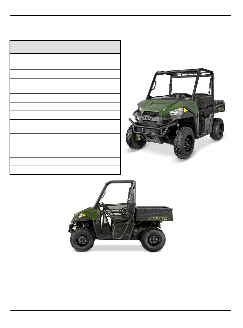
GENERAL INFORMATION
2021 RANGER 500
MODEL NUMBER:
2x4: R21MAA50B1, R21MAA50B7, R21MAA50J7, R21RM250A1
CATEGORY
Length
DIMENSION /
CAPACITY
110″ / 279.4 cm
Width 58″ / 147.3 cm
Height
73″ / 185 cm
Wheel Base 73″ / 185 cm
Ground Clearance 10″ / 25.4 cm
Turning Radius
150″ / 381 cm
Dry Weight 1080 lbs. / 490 kg
Cargo Box Capacity 500 lbs. / 227 kg
Cargo Box Dimensions
(inside dimensions)
L- 42″ x W-32″ x H-11.5″
(107 x 81 x 29 cm)
1000 lbs. / 454 kg
Vehicle Payload
(Includes weight of
riders, cargo and
accessories)
Towing Capacity 1500 lbs. / 680.4kg
Hitch Tongue Capacity 150 lbs. / 68 kg
1.46
9850043 R01 - 2017-2021 RANGER 500 / 570 Service Manual
© Copyright Polaris Inc.
Page 55

GENERAL INFORMATION
MODEL SPECIFICATIONS
ENGINE
Platform
Engine Displacement
Bore & Stroke 93 mm x 73.6 mm
Compression Ratio
Engine Idle Speed
Engine Max Speed 7000 RPM
Valve Clearance (Intake)
Valve Clearance (Exhaust)
Oil Requirements PS4 synthetic
Oil Capacity 2.0 qts. (1.9 l)
Coolant Capacity 120 Oz (3.5 L)
FUEL SYSTEM
Type Bosch ME17 EFI
Fuel Delivery Electronic Fuel Pump (in-
Fuel Pressure 58 ± 2 PSI (400 ± 14 kPa)
Fuel Capacity / Requirement 8.8 gal. (33.3 L) 87 Octane
ELECTRICAL
Alternator Max Output 560 W @ 3000 RPM
Headlights 2 single beam
Taillights / Brake Lights 10 LED 0.28 Watt / 3.1 Watt
Indicator Light 1.0 W
Ignition Timing ECU Controlled
Spark Plug / Gap Autolite 5923 / 0.030” - 0.037”
Battery / Amp Hr Yuasa Conventional 14 Amp
DC Outlet Standard 12 Volt
Relays EFI / Chassis / Fan / Fuel
Circuit Breaker Fan Motor: 20 Amp
Fuses Brake Light: 5 Amp
DRIVETRAIN
Transmission Type
Shift Type
Single overhead cam, 2 valve
4 stroke single cylinder.
500cc
10:1
1250 ±200 RPM
0.006 ± 0.002" (0.152 ± 0.051
mm)
0.010 ± 0.002" (0.254 ± 0.051
mm)
tank)
(minimum)
50W quartz/halogen
(0.85 +/- 0.08 mm)
Hr / 12 Volt
Pump / Headlight / EPS (EPS
model only)
EFI: 20 Amp
Fuel Pump: 10 Amp
EPS (EPS model only): 20
Amp
Accessory: 20 Amp
Drive: 10 Amp
Lights: 20 Amp
Polaris Automatic PVT
In Line Shift - P/ H / L / N / R
DRIVETRAIN
Front Gearcase Lubricant
Requirement
Transmission Lubricant
Requirement
STEERING / SUSPENSION
Toe Out 1/8 − 1/4″ (3.20 − 6.35 mm)
Front Suspension Strut / A-arm
Front Travel 9″ (20.3 cm)
Rear Suspension Independent (IRS), Dual A-
Rear Travel 10″ (22.9 cm)
Spring Adjustment Cam adjustment (rear)
WHEELS / BRAKES
Front Wheel Size / Type 12 x 8 / Steel
Rear Wheel Size / Type 12 x 9 / Steel
Front Tire Model / Size AT489 / 24 x 8 - 12
Rear Tire Model / Size AT489 / 24 x 9 - 12
Tire Air Pressure
Brake System 4 Wheel Hydraulic Disc
Brake Fluid DOT 4
Parking Brake Transmission - Park Lock
Demand Drive
6.7–7.6 oz. (200–225 ml)
Full Synthetic AGL
33.8 oz. (1000 ml)
arm, Anti-Sway Bar
Front: 10 psi (69 kPa)
Rear: 10 psi (69 kPa)
1
9850043 R01 - 2017-2021 RANGER 500 / 570 Service Manual
© Copyright Polaris Inc.
1.47
Page 56

GENERAL INFORMATION
2021 RANGER 570 4X4
MODEL NUMBER:
R21MAA57B1, R21MAA57B9
EPS: R21MAE57BX, R21MAE57D7
CATEGORY
Length
DIMENSION /
CAPACITY
110″ / 279.4 cm
Width 58″ / 147.3 cm
Height
73″ / 185 cm
Wheel Base 73″ / 185 cm
Ground Clearance 10″ / 25.4 cm
Turning Radius
150″ / 381 cm
1075 lbs. (488 kg) (570)
1100 lbs. (499 kg) (570
Dry Weight
EPS)
1140 lbs. (517 kg) (570
w/park)
Cargo Box Capacity 500 lbs. / 227 kg
Cargo Box Dimensions
(inside dimensions)
L- 42″ x W-32″ x H-11.5″
(107 x 81 x 29 cm)
1000 lbs. / 454 kg
Vehicle Payload
(Includes weight of
riders, cargo and
accessories)
Towing Capacity 1500 lbs. / 680.4kg
Hitch Tongue Capacity 150 lbs. / 68 kg
1.48
9850043 R01 - 2017-2021 RANGER 500 / 570 Service Manual
© Copyright Polaris Inc.
Page 57

GENERAL INFORMATION
MODEL SPECIFICATIONS
ENGINE
Platform
Engine Displacement
Bore & Stroke 99 x 73.6 mm
Compression Ratio
Compression Pressure
Engine Idle Speed
Engine Max Speed
Valve Clearance (Intake)
Valve Clearance (Exhaust)
Oil Requirements PS4 synthetic
Oil Capacity 2 qts. (1.9 L)
Coolant Capacity 120 Oz (3.5 L)
FUEL SYSTEM
Type Bosch ME17 EFI
Fuel Delivery Electronic Fuel Pump (in-
Fuel Pressure 58 ± 2 PSI (400 ± 14 kPa)
Fuel Capacity / Requirement 8.8 gal. (33.3 L) 87 Octane
ELECTRICAL
Alternator Max Output 560 W @ 3000 RPM
Headlights 2 single beam
Taillights / Brake Lights 10 LED 0.28 Watt / 3.1 Watt
Indicator Light 1.0 Watt
Ignition Timing ECU Controlled
Spark Plug / Gap NGK MR7F / 0.0276 −
Battery / Amp Hr Yuasa Conventional 14 Amp
DC Outlet Standard 12 Volt
Relays EFI / Chassis / Fan / Fuel
Circuit Breaker Fan Motor: 20 Amp
Fuses Brake Light: 5 Amp
Domestic Single Cyl., Liquid
Cooled, 4–Stroke, DOHC
567cc
10:1
80-120 psi (compression
release)
1200 +/- 100 RPM
7750 RPM
0.005-0.007″ (0.125–0.175
mm)
0.008 ± 0.002″ (0.152–0.254
mm)
tank)
(minimum)
50W quartz/halogen
0.0315″
(0.7 – 0.9 mm)
Hr / 12 Volt
Pump / Headlight / EPS (EPS
model only)
EFI: 20 Amp
Fuel Pump: 10 Amp
EPS (EPS model only): 20
Amp
Accessory: 20 Amp
Drive: 10 Amp
Lights: 20 Amp
DRIVETRAIN
Transmission Type
Shift Type
Front Gearcase Lubricant
Requirement
Transmission Lubricant
Requirement
STEERING / SUSPENSION
Toe Out 1/8 − 1/4″
Front Suspension Strut / A-arm
Front Travel 8″ (20.3 cm)
Rear Suspension Independent (IRS)
Rear Travel 9″ (22.9 cm)
Spring Adjustment Cam adjustment (rear)
WHEELS / BRAKES
Front Wheel Size / Type 12 x 6 / Steel
Rear Wheel Size / Type 12 x 8 / Steel
Front Tire Model / Size AT489 / 25 x 8 R12
Rear Tire Model / Size AT489 / 25 x 11 R12
Tire Air Pressure
Brake System 4 Wheel Hydraulic Disc
Brake Fluid DOT 4
Parking Brake Transmission - Park Lock
Polaris Automatic PVT
In Line Shift - P/ H / L / N / R
Demand Drive
6.7–7.6 oz. (200–225 ml)
Full Synthetic AGL
33.8 oz. (1000 ml)
(3.20 − 6.35 mm)
Front: 10 psi (69 kPa)
Rear: 10 psi (69 kPa)
1
9850043 R01 - 2017-2021 RANGER 500 / 570 Service Manual
© Copyright Polaris Inc.
1.49
Page 58
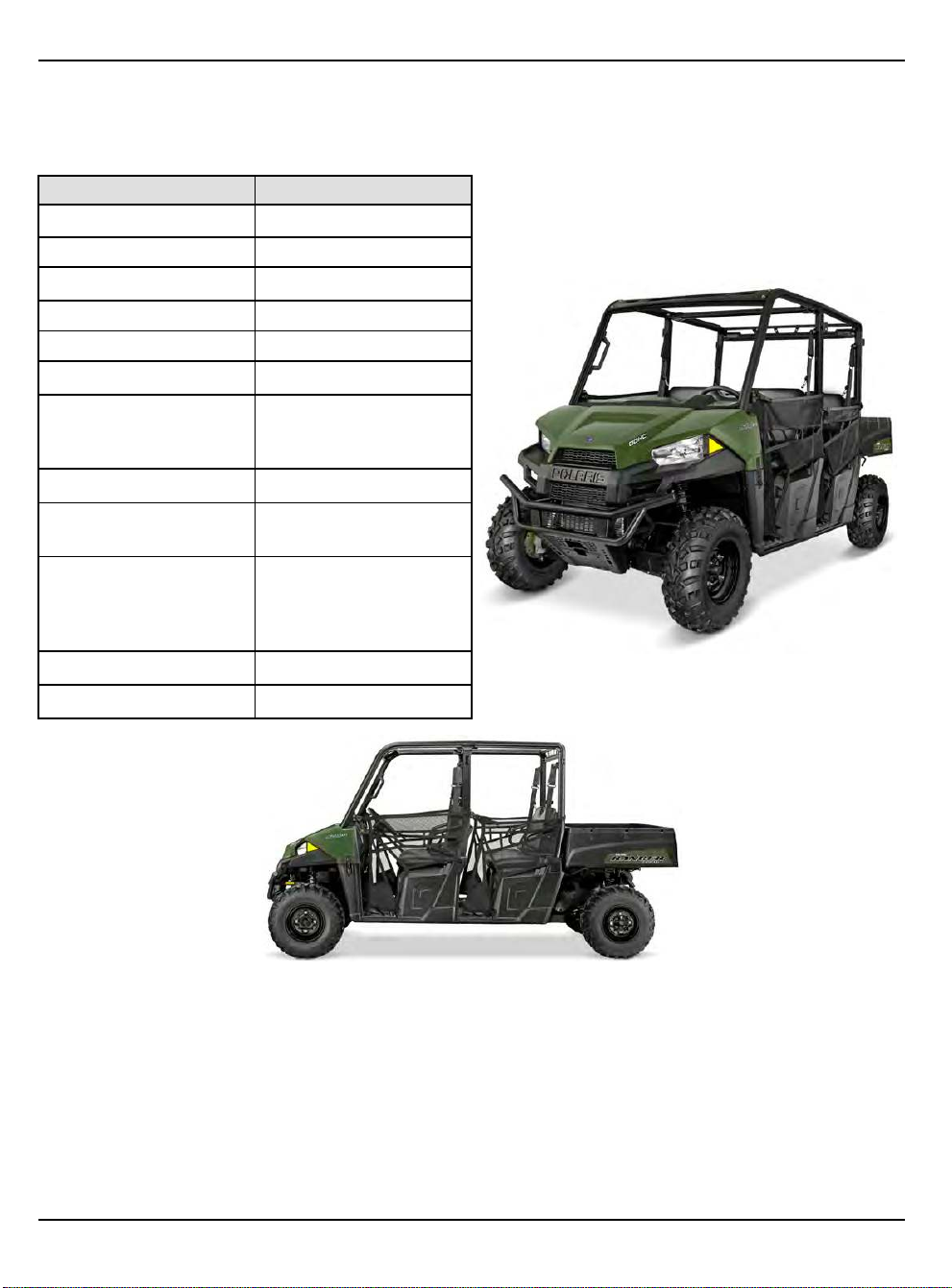
GENERAL INFORMATION
2021 RANGER 570 CREW
MODEL NUMBER:
R21M4A57B1, R21M4A57B9
EPS: R21M4E57BX
CATEGORY DIMENSION / CAPACITY
Length
140″ / 355.6 cm
Width
60″ / 152.4 cm
Height 73″ / 185 cm
Wheel Base 105″ / 266.7 cm
Ground Clearance 10″ / 25.4 cm
Turning Radius 237″ / 602 cm
Dry Weight
1323 lbs. / 600 kg
1352 lbs. / 613 kg (W /
EPS)
Cargo Box Capacity 500 lbs. / 227 kg
Cargo Box Dimensions
(inside dimensions)
L- 42″ x W-32″ x H-11.5″
(107 x 81 x 29 cm)
Vehicle Payload 1250 lbs. / 567 kg
(Includes weight of
riders, cargo and
accessories)
Towing Capacity 1500 lbs. / 680.4 kg
Hitch Tongue Capacity 150 lbs. / 68 kg
1.50
9850043 R01 - 2017-2021 RANGER 500 / 570 Service Manual
© Copyright Polaris Inc.
Page 59

GENERAL INFORMATION
MODEL SPECIFICATIONS
ENGINE
Platform
Engine Displacement
Number of Cylinders
Bore & Stroke 99 x 73.6 mm
Compression Ratio
Compression Pressure
Engine Idle Speed
Engine Max Speed
Valve Clearance (Intake)
Valve Clearance (Exhaust)
Lubrication
Oil Requirements PS4 synthetic
Oil Capacity 2 qts. (1.9 L)
Coolant Capacity 170 Oz (5 L)
FUEL SYSTEM
Type Bosch M17 EFI
Fuel Delivery Electronic Fuel Pump (in-
Fuel Pressure 58 ± 2 PSI (400 ± 14 kPa)
Fuel Capacity / Requirement 8.8 gal. (33.3 L) 87 Octane
ELECTRICAL
Alternator Max Output 560 W @ 3000 RPM
Headlights 2 single beam
Taillights / Brake Lights 10 LED 0.28 Watt / 3.1 Watt
Indicator Lamp 1.0 Watt
Ignition Timing ECU Controlled
Spark Plug / Gap NGK MR7F / 0.0276 −
Battery / Amp Hr Yuasa Conventional 14 Amp
DC Outlet Standard 12 Volt
Instrumentation Multifunction Instrument
Relays EFI / Chassis / Fan / Fuel
Domestic Single Cyl., Liquid
Cooled, 4–Stroke, DOHC
567cc
1
10:1
80-120 psi (compression
release)
1200 +/- 100 RPM
7750 RPM
0.005–0.007″ (0.125–0.175
mm)
0.008 ± 0.002″ (0.152–0.254
mm)
Pressurized Dry Sump
tank)
(minimum)
50W quartz/halogen
0.0315″
(0.7 – 0.8 mm)
Hr / 12 Volt
Cluster
Pump / Headlight / EPS (EPS
model only)
ELECTRICAL
Circuit Breaker Fan Motor: 20 Amp
Fuses Brake Light: 5 Amp
DRIVETRAIN
Transmission Type
Shift Type
Front Gearcase Lubricant
Requirement
Transmission Lubricant
Requirement
STEERING / SUSPENSION
Toe Out 1/8 − 1/4″ (3.20 − 6.35 mm)
Front Suspension Strut / A-arm
Front Travel 8″ (20.3 cm)
Rear Suspension Independent (IRS)
Rear Travel 9″ (23 cm)
Spring Adjustment Cam Adjustment (rear)
WHEELS / BRAKES
Front Wheel Size / Type 12 x 6 / Steel
Rear Wheel Size / Type 12 x 8 / Steel
Front Tire Model / Size AT489 / 25 x 8 R12
Rear Tire Model / Size AT489 / 25 x 11 R12
Tire Air Pressure Front: 10 psi
Brake System 4 Wheel Hydraulic Disc
Brake Fluid DOT 4
Parking Brake Transmission — Park Lock
EFI: 20 Amp
Fuel Pump: 10 Amp
EPS (EPS model only): 20
Amp
Accessory: 20 Amp
Drive: 10 Amp
Lights: 20 Amp
Polaris Automatic PVT
In Line Shift - P/ H / L / N / R
Demand Drive
8.97 oz. (265 ml)
Full Synthetic AGL
33.8 oz. (1000 ml)
Rear: 14 psi
1
9850043 R01 - 2017-2021 RANGER 500 / 570 Service Manual
© Copyright Polaris Inc.
1.51
Page 60

GENERAL INFORMATION
MISC. SPECIFICATIONS AND CHARTS
CONVERSION TABLE
UNIT OF MEASURE MULTIPLIED BY CONVERTS TO
ft-lbs x 12 = in-lbs
in-lbs x 0.0833
ft-lbs
in-lbs x 0.0115 = kg-m
Nm x 0.7376
kg-m x 7.233
kg-m x 86.796 = in-lbs
kg-m x 10 = Nm
inch x 25.4
mm
inch x 2.54
mile (mi)
km x 0.6214 = mile
ounces (oz) x 28.35 = grams (g)
fluid ounces (fl oz)
cubic centimeters (cc)
grams (g) x 0.035
pounds (lb)
kilogram (kg)
cubic inches (cu in) x 16.387
cubic centimeters (cc)
US quarts
liters (L) x 1.057 = US quarts
US gallons
liters (L) x 0.264 = US gallons
PSI
kilopascals (kPa)
π (3.14) x Radius² x Height =
°C to °F: 9/5 (°C + 32) = °F
°F to °C: 5/9 (°F − 32) = °C
x 1.356 = Nm
x 0.03937 = inch
x 1.6 = km
x 29.57
x .03381
x 0.454 = kg
x 2.2046 = lbs
x 0.061 = cubic inches
x 0.946
x 3.785
x 6.895
x 0.145
= ft-lbs
= ft-lbs
= ft-lbs
= mm
= cm
= cubic centimeters (cc)
= fluid ounces
= ounces
= cc
= liters (L)
= liters (L)
= kilopascals (kPa)
PSI
= cylinder volume
1.52
9850043 R01 - 2017-2021 RANGER 500 / 570 Service Manual
© Copyright Polaris Inc.
Page 61

GENERAL INFORMATION
SAE TAP / DRILL SIZES
THREAD SIZE DRILL SIZE THREAD SIZE DRILL SIZE
#0–80 3/64 1/2–13 27/64
#1–64 53 1/2–20 29/64
#1–72 53 9/16–12 31/64
#2–56
#2–64
#3–48 5/64 5/8–18 37/64
#3–56
#4–40
#4–48
#5–40 38 7/8–14 13/16
#5–44 37 1–8 7/8
#6–32
#6–40
#8–32
#8–36
#10–24
#10–32 21 1 1/2–6 1 11/32
#12–24 17 1 1/2–12 1 27/64
#12–28
1/4–20
1/4–28
5/16–18
5/16–24
3/8–16 O 2 1/2–4 2 1/4
3/8–24 Q 2 3/4–4 2 1/2
7/16–14
7/16–20 25/64
51
50
45
43
42
36 1–12
33
29
29
24
4.6 mm
7
3
F 2–12
I
U 3–4
2 1/4–4 1/2 2 1/32
9/16–18 33/64
5/8–11 17/32
3/4–10 21/32
3/4–16 11/16
7/8–9 49/64
1 1/8–7 63/64
1 1/8–12 1 3/64
1 1/4–7 1 7/64
1 1/4–12 1 11/64
1 3/4–5 1 9/16
1 3/4–12 1 43/64
2–4 1/2 1 25/32
1
59/64
1 59/64
2 3/4
9850043 R01 - 2017-2021 RANGER 500 / 570 Service Manual
© Copyright Polaris Inc.
1.53
Page 62
GENERAL INFORMATION
METRIC TAP / DRILL SIZES
TAP SIZE DRILL SIZE
3 x .50 #39 0.0995 3/32
3 x .60
4 x .70
4 x .75
5 x .80
5 x .90 #20 0.161 5/32
6 x 1.00
7 x 1.00 16/64 0.234 15/64
8 x 1.00 J 0.277
8 x 1.25
9 x 1.00
9 x 1.25
10 x 1.25
10 x 1.50 R 0.339
11 x 1.50 3/8 0.375 3/8
12 x 1.50
12 x 1.75
DECIMAL EQUIVALENT
3/32
#30
1/8 0.125 1/8
#19
#9
17/64
5/16
5/16
11/32
13/32
13/32
0.0937
0.1285
0.166
0.196
0.265
0.3125
0.3125
0.3437
0.406
0.406
NEAREST FRACTION
3/32
1/8
11/64
13/64
9/32
17/64
5/16
5/16
11/32
11/32
13/32
13/32
1.54
9850043 R01 - 2017-2021 RANGER 500 / 570 Service Manual
© Copyright Polaris Inc.
Page 63

DECIMAL EQUIVALENTS
FRACTION DECIMAL MM TO INCHES
1/64 0.0156″
1/32
3/64
1/16 0.0625″
5/64
3/32
7/64 0.1094″ 3 mm = 0.1181″
1/8
9/64
5/32 0.1563″ 4 mm = 0.1575″
11/64 0.1719″
3/16
13/64
7/32 0.2188″
15/64
1/4
17/64 0.2656″ 7 mm = 0.2756″
9/32
19/64
5/16 0.3125″ 8 mm = 0.3150″
21/64
11/32
23/64 0.3594″
3/8 0.375″
25/64
13/32
27/64 0.4219″ 11 mm = 0.4331″
7/16
29/64
15/32 0.4688″ 12 mm = 0.4724″
31/64
1/2
33/64 0.5156″
17/32 0.5313″
35/64
9/16
37/64 0.5781″ 15 mm = 0.5906″
19/32
39/64
5/8
GENERAL INFORMATION
1
0.0312″ 1 mm = 0.0394″
0.0469″
0.0781″ 2 mm = 0.0787″
0.0938″
0.1250″
0.1406″
0.1875″ 5 mm = 0.1969″
0.2031″
0.2344″ 6 mm = 0.2362″
0.25″
0.2813″
0.2969″
0.3281″
0.3438″ 9 mm = 0.3543″
0.3906″ 10 mm = 0.3937″
0.4063″
0.4375″
0.4531″
0.4844″
0.500″ 13 mm = 0.5118″
0.5469″ 14 mm = 0.5512″
0.5625″
0.5938″
0.6094″
0.625″ 16 mm = 0.6299″
9850043 R01 - 2017-2021 RANGER 500 / 570 Service Manual
© Copyright Polaris Inc.
1.55
Page 64

GENERAL INFORMATION
FRACTION DECIMAL MM TO INCHES
41/64
21/32 0.6563″ 17 mm = 0.6693″
43/64
11/16
45/64 0.7031″ 18 mm = 0.7087″
23/32 0.7188″
47/64
3/4
49/64 0.7656″
25/32
51/64
13/16 0.8125″ 21 mm = 0.8268″
53/64
27/32
55/64
7/8 0.875″
57/64
29/32
59/64 0.9219″
15/16
61/64
31/32 0.9688″ 25 mm = 0.9843″
63/64
1 1.000″
0.6406″
0.6719″
0.6875″
0.7344″ 19 mm = 0.7480″
0.750″
0.7813″ 20 mm = 0.7874″
0.7969″
0.8281″
0.8438″
0.8594″ 22 mm = 0.8661″
0.8906″ 23 mm = 0.9055″
0.9063″
0.9375″ 24 mm = 0.9449″
0.9531″
0.9844″
1.56
9850043 R01 - 2017-2021 RANGER 500 / 570 Service Manual
© Copyright Polaris Inc.
Page 65

GENERAL INFORMATION
GENERAL DIAGNOSTICS
GENERAL DIAGNOSTICS INFORMATION OVERVIEW
NOTICE
General Diagnostics is a section within the Service Manual that contains information relating to various vehicle
diagnostics. These procedures are not vehicle specific and can be used for troubleshooting many different vehicles.
For vehicle specific troubleshooting and diagnostic information please refer to the specific system chapters for more
GUIDED SYMPTOM DIAGNOSTIC
Is this the first time that the
vehicle concern has been
diagnosed?
↓
Yes
Has the concern been
duplicated and compared to a
like vehicle?
→
No
→
No
information.
Refer to Guided Symptom
References
If the concern has not been
able to be duplicated gather
more information about the
concern. After the concern
has been duplicated, please
compare to a like vehicle. Is
the concern present on that
vehicle?
→
Yes
If the same concern is present
on the like vehicle, it is likely
that the concern is a normal
operational characteristic.
1
Yes
↓
Are there any bulletins related
to the concern?
No ↓
Connect Digital Wrench and
check for any trouble codes.
Are there any codes present?
No
↓
9850043 R01 - 2017-2021 RANGER 500 / 570 Service Manual
© Copyright Polaris Inc.
No
↙
→
Yes
No
↙
→
Yes
No
↙
Proceed with instruction from
the bulletin. Has the problem
Has concern been repaired
after Guided Diagnostic?
been resolved?
Refer to Digital Wrench
Guided Diagnostic.
→
Yes
→
Yes
Concern has been repaired.
Return the vehicle to the
consumer at this time.
Concern has been repaired.
Return the vehicle to the
consumer at this time.
1.57
Page 66

GENERAL INFORMATION
Is the concern Starting
Related?
No
↓
Is the concern related to
Engine Performance or a
Running concern?
No
↓
→
Yes
→
Yes
Refer to, Engine Cranks but
does Not Start page 1.62 or
No Crank No Start or Slow
Crank page 1.64.
Pay close attention to what is
noted in the Occurrence
Checklist for conditions when
concern is present. This will
help in determining cause of
concern.
Refer to Engine and
Drivability Diagnostic
Procedures page 1.59.
Pay close attention to what is
noted in the Occurrence
Checklist for conditions when
concern is present. This will
help in determining cause of
concern.
Have any concerns in the
Transmission / Final Drive
Category been selected?
No
↓
Is the concern related to a
GUIDED SYMPTOM REFERENCES
• For concerns that have not been able to be duplicated or are repeat concerns :
– Refer to the Customer Questionnaire and gather more information from the Consumer.
– Gather the information from previous repairs including Ask Polaris Cases.
– Verify that the concern can be consistently duplicated. When the concern is duplicated, please note the conditions
under which the concern is happening. Refer to the Symptom Checklist for various conditions.
– If the concern has been verified and all of the information has already been collected, please start an Ask Polaris
case at this time. If this information has not yet been gathered, gather this information first.
Noise?
→
→
Yes
Refer to the Transmission or
Final Drive Chapters for
further diagnostic information.
Refer to necessary service
information for pin-pointing
noise location and diagnosis.
1.58
9850043 R01 - 2017-2021 RANGER 500 / 570 Service Manual
© Copyright Polaris Inc.
Page 67
GENERAL INFORMATION
ENGINE AND DRIVABILITY DIAGNOSTIC PROCEDURES
NOTICE
The following chart is to prevent overlooking a simple problem. These basic systematic procedures should be
checked before further testing is performed.
1
What is the
q
customers concern
and can the concern
be duplicated at this
time?
Are there any
w
Team-Tips, Recalls,
or Other Bulletins for
this concern?
Are there any
e
warning lights or
messages on
vehicle? (Reference
necessary manual
for light
identification)
Yes
No
Yes
No
Yes
• Proceed to step
• If the concern can not be duplicated, check for any bulletins related to the
concern. Gather more information from the consumer. Proceed to step
the concern still can not be duplicated proceed to step
• Proceed to bulletin for repair procedure. If problem is still present, return to
chart.
• Proceed to step
• For CHECK ENGINE LIGHT or PERFORMANCE LIMITED LIGHT
– Connect to Digital Wrench®. Check codes and continue with Digital
Wrench® Guided diagnosis.
– Certain failures may not display a CEL / MIL on the instrument cluster. In
this instance record CEL’s from the instrument cluster and refer to the
necessary section in the Service Manual.
– Refer to Warning Lights page 1.66.
• For ENGINE HOT WARNING
– Check Coolant level. If not full, fill to correct level.
– Check Oil level. If not full, fill to correct level.
– Visually inspect for Oil or Coolant leaks. If any leaks are present repair
before continued diagnosis.
– Refer to Warning Lights page 1.66.
– Refer to Over Heating page 1.65.
• For EPS WARNING (if applicable) Refer to STEERING - EPS
TROUBLESHOOTING.
– Check battery voltage and connections.
– Check connections at EPS unit. If any connection or wiring damage is
found, repair before proceeding.
– Refer to EPS Troubleshooting (Using Digital Wrench®) page 1.100.
Check codes and continue with diagnosis.
– If no codes are present, refer to EPS Troubleshooting (Power Steering
Non-Functional with MIL OFF) page 1.99
– If codes are present, refer to EPS Troubleshooting (Power Steering Non-
Functional with MIL ON) page 1.98
w
e
u
.
e
. If
• Connect to Digital Wrench®. Check codes and continue with Digital
No
9850043 R01 - 2017-2021 RANGER 500 / 570 Service Manual
© Copyright Polaris Inc.
Wrench® Guided diagnosis.
• If no codes are present, proceed to step
r
1.59
Page 68

GENERAL INFORMATION
Yes
• Check Oil level. If not full, fill to correct level.
• Check Fuel Level. (Check tank using flash light - gauge may not be accurate
- add fuel if needed)
• Check Coolant level. If not full, fill to correct level.
Continue to step
t
Does the engine
r
crank?
Does the engine
t
stay running?
No
Yes
No
• Check Oil level. If oil is low concern may be caused by lack of oil or oil
pressure. Suspect internal engine issue. Refer to Chapter 3 Engine / Cooling
System.
• Check for battery power. Voltage should be ~ 12.6 V.
• Load test battery. If battery fails the load test, charge / replace battery as
needed. Retest for concern before proceeding.
• Check Ignition Switch and connections. Concern may be caused by faulty
Ignition Switch.
• Refer to No Crank No Start or Slow Crank page 1.64 for further diagnostic
procedures
• Continue to step
• Check air filter for blockage.
• Check for spark. Refer toEngine Cranks but does Not Start page 1.62 for
quick check.
• Check fuel supply using fuel pressure gauge. Is fuel pressure within
specification?
• Check exhaust for blockage.
• After checking for air supply and fuel pressure, perform leakdown test.
• Refer to Engine Cranks but does Not Start page 1.62 for more information.
y
1.60
9850043 R01 - 2017-2021 RANGER 500 / 570 Service Manual
© Copyright Polaris Inc.
Page 69

GENERAL INFORMATION
Will the vehicle
y
move under its own
power?
Test drive vehicle
u
for concern.
Yes
No
• Continue to step
• Remove PVT cover if necessary and check belt for damage or unusual wear.
Refer to Belt Inspection for more information.
• If no damage is found, using the aid of an assistant slowly rev engine
observing clutch engagement. If no engagement is seen refer to PVT System
Troubleshooting.
• Using the aid of an assistant verify the propshaft is turning, while the clutch is
engaged. If the driveshaft is turning refer to Differential Diagnosis /
Disassembly in the applicable service manual.
• If the driveshaft is not moving, concern may be within transmission. Refer to
the necessary section in the applicable service manual.
• If the concern is related to the PVT system, Transmission, or Final Drive,
refer to the applicable section in the service manual.
• If the concern is electrical systems related, refer to Electrical
Troubleshooting.
• If the concern is overheating or related to the cooling system, first refer to
Over Heating page 1.65 , then Cooling Troubleshooting page 1.69.
• If the concern is driveability related (lack of power, misfire, etc.), refer to Fuel
System Troubleshooting page 1.89, or Cylinder Misfire Detection page 1.87.
These concerns may also be caused by a mechanical failure.
• If the concern can not be diagnosed or repaired using normal diagnostic
means, please contact Polaris Technical Service Team.
u
1
9850043 R01 - 2017-2021 RANGER 500 / 570 Service Manual
© Copyright Polaris Inc.
1.61
Page 70

GENERAL INFORMATION
ENGINE CRANKS BUT DOES NOT START
1. Check battery voltage while cranking. If voltage is
below 10.8V, vehicle may not start.
• Perform Voltage Drop Test on Starter Circuit. Refer
to Testing Voltage Drop page 1.107 for more
information. Acceptable drop is 0.1V per
connection, if too much drop is detected concern
may be caused by faulty starter, or solenoid.
• Charge battery.
• If equipped with a serviceable battery, check
battery electrolyte level. Fill following procedure if
low.
• If battery voltage is not ~12.6 V charge battery at
recommended rate. Attempt starting after charging.
• If battery still does not reach ~12.6 V, battery may
require replacement.
2. Visually inspect vehicle for any electrical connectors
or wiring that may be loose or damaged. Check
connectors for water intrusion or corrosion.
• If connections are found to be loose, repair
connector as necessary.
• If connector is found to have corrosion or water
within connectors, clean, dry, and reconnect.
• Repair any damage to wiring.
3. Check vehicle for trouble codes. Refer to Digital
Wrench® Diagnostic.
• If codes are present proceed with testing per Digital
Wrench®.
4. Check air box and filter for debris or moisture.
• If debris is found clear debris and recheck for
concern.
• If water is found within air box, dry box and filter. It
is possible that engine may have ingested water.
This could cause engine failure, refer to Engine
Troubleshooting page 1.67
5. Check fuel level and condition in vehicle.
• Possible to have incorrect reading from fuel gauge.
Using a flashlight, check for fuel in tank. If no fuel is
visible, fill with fuel before further diagnostic.
• Check fuel quality, pull fuel sample or drain tank
and refill with fresh fuel from a reliable source.
IMPORTANT
When filling with fuel, ensure that the fuel being used
meets the correct octane rating specific to the vehicle.
6. Check fuses or fuel system relays (where applicable).
• If any fuel related system fuses are blown, replace
fuses and recheck. Wiring concern or faulty parts may
cause fuse to blow.
• It is advisable to try swapping a relay with a known
good relay to check operation. Swap relay with like
relay and see if vehicle starts.
7. Check fuel lines and fittings for leaks or damage.
• If leak or damage is found repair, replace as
necessary and recheck concern.
• If no concerns are found proceed with fuel pressure
testing.
8. Perform a fuel pressure test during engine cranking.
• Verify that battery voltage is present at the fuel
pump. A low voltage concern may cause the pump
to be inoperable.
• Check using fuel pressure gauge to see that fuel
pressure is within specification.
• If not within specification, if equipped check fuel
filter / screen for restriction.
• If no concern is found with filter or pressure is still
low after filter replacement, suspect weak or faulty
fuel pump.
9. Inspect spark plug wiring, spark plug, and check for
spark.
• Check to make sure that spark plug is tight.
• Inspect spark plug for fouling. Inspect plug gap
using feeler gauge or similar tool. Adjust to
specification if needed.
• Disconnect plug wire and install an inline spark
tester between the spark plug wire and spark plug.
Check for spark. If a spark tester is not available,
remove the spark plug and reinstall wire to plug
connection. Using caution crank engine while
watching spark plug for spark.
CAUTION
DO NOT TOUCH SPARK PLUG DURING TEST.
TOUCHING SPARK PLUG COULD RESULT IN
ELECTRIC SHOCK.
• If plug does not spark in previous test, check
connections at ignition coil. Ensure that the ignition
coil has power and is receiving signal from the
ECU. Concern may be caused by faulty ignition coil
or electrical concern.
• If filled with fuel, vehicle starts, and gauge still is not
reading test the fuel sending unit.
1.62
10.Listen for unusual noises while cranking.
9850043 R01 - 2017-2021 RANGER 500 / 570 Service Manual
© Copyright Polaris Inc.
Page 71

• Broken or damaged flywheel, starter motor gear, or
starter motor drive could sound like engine
cranking but crankshaft may not be turning.
• Unusual noise could suggest that there may be a
mechanical engine concern. Proceed to step
11.Check ECU and connections.
• ECU could be faulty causing concern.
• Check ECU for power and grounds to make sure that
computer is turning on.
12.If all previous checks pass, concern may be caused
by internal engine issue.
• Refer to Cylinder Leakdown Test.
• Previous testing may be caused by or lead to
replacement of one or more of the following:
– Cylinder head gasket leak
– No valve clearance (cam wear)
– Cylinder or piston worn
– Piston rings worn, leaking, broken, or sticking
– Bent valve or stuck valve
– Valve spring broken or weak
– Valve not seating properly (bent or carbon
accumulated on sealing surface)
– Rocker arm sticking
f
GENERAL INFORMATION
1
9850043 R01 - 2017-2021 RANGER 500 / 570 Service Manual
© Copyright Polaris Inc.
1.63
Page 72

GENERAL INFORMATION
NO CRANK NO START OR SLOW CRANK
1. Verify that battery is charged and has ~12.6 V using
DMM or battery tester.
• Check battery electrolyte level. If low top off battery.
See Maintenance — Electrical and Ignition
Systems.
• Charge battery at recommended rate. See. Attempt
starting after charging.
• If battery will not reach ~12.6 V could be caused by
battery draw. Refer to Diagnostic — Electrical
Diagnostics.
• If battery will not reach ~12.6 V, load test battery.
Replace if necessary. Refer to Electrical — Battery
Removal / Installation.
2. Verify connections at battery are installed correctly
and are tight.
• If battery terminals are not installed correctly, install
terminals correctly
• Make sure terminals are clean of dirt and corrosion.
If not refer to Maintenance — Battery Maintenance.
3. Visually inspect vehicle for any electrical connectors
or wiring that may be loose or damaged.
• If wiring issues are found, repair as necessary.
Refer to wiring diagrams if needed.
• Check battery ground. Follow Negative (-) Cable
from battery to chassis and make sure connection
is clean and tight.
• Using Digital Wrench® verify that the Brake Switch
is changing state from “Active” when the brake is
depressed to “Inactive” when the brake is released.
• Most vehicles need to see brake being depressed
before vehicle will start. If brake lights do not light
when brake is depressed, concern may be caused
by brake switch operation.
6. Possible faulty key switch.
• Attempt turning key switch on and off multiple
times.
• Wiggle key switch while turning.
• If vehicle starts, concern may be caused by key
switch or connection to switch. Refer to Electrical
Chapter.
7. Check for communication with ECU using Digital
Wrench®
• If there is no communications with ECU there may
be a concern with the CAN system or ECU causing
the no start.
8. Concern may be caused by mechanical engine
concern.
• Refer to Engine Troubleshooting.
4. Check connections at starter and starter solenoid.
Refer to Electrical Chapter.
• Make sure connections are clean and tight. If not
repair before further diagnosis.
• Check Positive (+) terminals at starter and solenoid
for available voltage using DMM. Readings should
be ~12.6 V
• With battery disconnected check cables for high
resistance. Reading should be less than 1 Ohm. If
resistance is higher than specification replace
wiring.
• Reconnect battery and perform voltage drop test
on wiring to starter and to starter solenoid. Concern
may still be caused by high resistance in wires
even if resistance is within specification when
disconnected.
• If voltage drop test fails, continue testing to isolate
component that will require replacement (starter /
starter solenoid / wiring). Acceptable voltage drop
during cranking is 0.1 V per connection.
5. Check Brake Switch operation.
1.64
9850043 R01 - 2017-2021 RANGER 500 / 570 Service Manual
© Copyright Polaris Inc.
Page 73

GENERAL INFORMATION
OVER HEATING
1. Verify coolant is filled to correct level.
• If coolant is low, fill to correct level.
2. Test and check for correct coolant mixture.
• If coolant mix is incorrect, correct mixture as
necessary.
• If incorrect coolant was used in vehicle, flush cooling
system and bleed, fill to correct level, and recheck.
3. Check cooling system using combustion leak tester
for any combustion gasses entering the cooling
system. This may suggest a head gasket, cylinder
head failure, or other engine damage. Adding coolant
before test may dilute the system and cause
inaccurate test results.
4. Check Radiator and cooling fans for restrictions or
damage
• Check for debris, dirt, or mud between fan and
radiator restricting air flow. If present, clean and
recheck.
• Check for damage to radiator or cooling fans. If
damage is found to components repair or replace
as necessary.
• Inspect for any aftermarket modifications that may
be restricting air flow. (Radiator Modifications, Grille
Modifications, Aftermarket Bumpers, Lightbars,
etc.) Pay close attention to the Radiator Shroud
presence and placement.
5. Check for coolant leaks / air pockets.
• Visually check all hoses and radiator for leaks. If
leaks are found repair as necessary.
• Check cooling system using coolant pressure
tester. If leaks can not be seen on visual inspection,
refer to Engine / Cooling system for more
information.
• Check for air in cooling system. Bleed the cooling
system if needed.
6. Check Oil level.
• Low oil level or oil in need of changing may cause
increase in engine temperature.
• Too high of oil level may cause engine
temperatures may cause increase in engine
temperature.
• Check level and correct as necessary. Check
maintenance history to determine if oil need to be
changed.
• Make sure the cooling fan is engaging. Command
cooling fans on and off using Digital Wrench to
check operation.
• Monitor engine temperature using Digital Wrench®
viewing the Engine Temperature PID. Once engine
has reached running temperature cooling fan
should engage.
8. Water Pump / Thermostat / Radiator may be suspect
of concern.
• Thermostat could be opening too slowly or stuck
closed. Check temperature using Digital Wrench®
viewing the Engine Temperature to check for
correct operation.
• Water pump may be faulty or not circulating
enough coolant to keep temperature within
specification.
• Radiator core may not be functioning correctly or
failed causing concern.
9. Faulty Temp Sensor / Circuit / ECU.
• Confirm engine is overheating. It could be possible
that the coolant sensor is sending an incorrect
signal causing the ECU to think the vehicle is
overheating when it is running at the proper
temperature.
• Check connections at temp sensor and wiring. If
damage is found repair, as needed.
• Resistance test sensor, refer to ECT Sensor test. If
test fails, replace sensor.
• If concern is still present after sensor replacement
suspect the ECU is not receiving correct signal
input. Inspect circuit wiring.
10.Engine Damage
• The overheating concern may be caused by an
engine concern.
• Refer to the necessary section in the Service
Manual for further engine testing.
11.Inspect ECU calibration level.
• If any ECU calibrations are available, update at this
time.
1
7. Check Cooling Fan operation.
9850043 R01 - 2017-2021 RANGER 500 / 570 Service Manual
© Copyright Polaris Inc.
1.65
Page 74

GENERAL INFORMATION
WARNING LIGHTS
1. CHECK ENGINE
• Engine fault has been detected. Refer to Digital
Wrench for codes.
• Proceed with diagnosis after checking codes.
2. EPS WARNING (If applicable)
• Power steering fault has been detected.
• Check for codes using Digital Wrench. If no codes
present refer to EPS System – Troubleshooting
• Check connections at battery, could be caused by
voltage concern.
• Visually inspect connections at EPS Unit.
• For further diagnosis refer to Steering System –
Steering Assembly EPS
3. ENGINE HOT
• Over temperature condition detected.
• Check coolant level. If not full fill to correct level.
Bleed the cooling system to ensure there are no air
pockets present.
• Visually inspect hoses and radiator for coolant
leaks. Repair as necessary.
• Pressurize cooling system and look for pressure
losses. This indicates a leak in the cooling system.
Inspect for external leaks, if none are found it is
possible there is an internal leak.
• Check cooling system using combustion leak tester
for any combustion gasses entering the cooling
system. This could indicate possible Head /
Headgasket failure.
• Check oil level. Verify that oil is filled to the correct
level. Engine oil that is low, or overfull can cause
overheating concerns. Check maintenance history
to see if oil needs to be changed.
• Visually inspect for oil leaks.
• Refer to Over Heating page 1.65 for more info.
4. PERFORMANCE LIMITED
• Check for codes using Digital Wrench. Refer to
Guided Diagnostic for further diagnosis.
5. BRAKE WARNING
• Detects brake system failure.
• Inspect brake system for leaks, damage, etc. Refer
to Brake System chapter for more information.
1.66
9850043 R01 - 2017-2021 RANGER 500 / 570 Service Manual
© Copyright Polaris Inc.
Page 75

ENGINE TROUBLESHOOTING
SPARK PLUG FOULING
GENERAL INFORMATION
1
• Spark plug cap loose or faulty
• Incorrect spark plug heat range or
gap
• PVT system calibrated incorrectly/
components worn or mis-adjusted
• Fuel quality poor (old) or octane
too high
• Improperly assembled air intake
system
ENGINE TURNS OVER BUT FAILS TO START
• No fuel
• Dirt in fuel line or filter
• Fuel will not pass through fuel
valve
• Clogged / Failed Fuel Injector
• Battery, Starter, and Ground Cable
Connections
• Engine seized, rusted, or
mechanical failure
• Injector Spray Pattern
• High Leakdown
• Valvetrain / Valve Clearances
• Restricted exhaust
• Vehicle not reaching operating
temperature (Short tripping)
• Fuel pump inoperative/restricted
• Tank vent plugged or pinched
• Engine flooded
• Injector control circuit failure
ENGINE DOES NOT TURN OVER
• Starter motor does not turn
• Starting system circuit concern
(blown fuse / failed relay /
damaged wiring)
• Oil contaminated with fuel
• Weak ignition (loose coil ground,
faulty coil, or stator)
• Restricted engine breather system
• Restricted air filter (main or precleaner) or breather system
• Low compression (high cylinder
leakage)
• No spark (Spark plug fouled)
ignition component failure
• Intake leak / vacuum leak
• Dead battery
ENGINE RUNS BUT WILL NOT IDLE
• Restricted fuel supply
• Intake leak / vacuum leak
• Spark plug fouled/weak spark
• Broken throttle cable
• Obstruction in air intake
9850043 R01 - 2017-2021 RANGER 500 / 570 Service Manual
© Copyright Polaris Inc.
• Low compression
• TPS (installed incorrect / electrical
concern / failed sensor)
ENGINE IDLES BUT WILL NOT ACCELERATE
• Air box removed (reinstall all
intake components)
• Incorrect ignition timing
• Throttle Body
• Throttle Body (installed incorrect /
electrical concern / failed)
• Crankcase breather restricted
• Cam worn excessively
• Restricted exhaust system
• Low fuel pressure
1.67
Page 76
GENERAL INFORMATION
ENGINE HAS LOW POWER
• Spark plug fouled
• Cylinder, piston, ring, or valve
wear or damage (check
compression)
• Poor fuel quality
• Lack of lubrication
• Improper air filter maintenance
EXCESSIVE SMOKE (BLUE / BLACK) AND CARBON BUILDUP
• Excessive piston-to-cylinder
clearance
• Wet sumping
• Cylinder head gasket leak
• No valve clearance (cam wear)
• Valve not seating properly (bent or
carbon accumulated on sealing
surface)
• PVT not operating properly
• Cam worn excessively
PISTON FAILURE - SCORING
• Dirt entering engine through
cracks in air filter or ducts
• Worn rings, piston, or cylinder
• Worn valve guides or seals
LOW COMPRESSION
• Cylinder or piston worn
• Bent valve or stuck valve
• Restricted exhaust muffler
• Low fuel pressure
• Engine oil dirty or contaminated
• Restricted breather
• Air filter dirty or contaminated
• Piston rings worn, leaking, broken,
or sticking
• Valve spring broken or weak
• Ignition system faulty:
– Spark plug cap cracked /
broken
– Ignition coil faulty
– Ignition or kill switch circuit
faulty
– Poor connections in ignition
system
– Ignition timing incorrect
– Sheared flywheel key
1.68
BACKFIRING
• Intake system air leaks
• Fouled spark plug or incorrect plug
or plug gap
• Low fuel pressure
• Poor fuel quality
9850043 R01 - 2017-2021 RANGER 500 / 570 Service Manual
• Exhaust system air leaks
• Valve sticking
• Throttle Body (installed incorrect /
electrical concern / failed)
© Copyright Polaris Inc.
Page 77

COOLING TROUBLESHOOTING
OVERHEATING
GENERAL INFORMATION
1
• Low coolant level
• Air in cooling system
• Wrong type/mix of coolant
• Faulty pressure cap or system
leaks
• High oil level
• Spark plug incorrect heat range
• Radiator
• Faulty water pump mechanical seal (coolant leak) • Faulty pump shaft oil seal (oil leak)
• Thermostat stuck open
• Thermostat opening too soon
• Restricted system (mud or debris
in radiator fins causing restriction
to air flow, passages blocked in
radiator, lines, pump, or water
jacket, accident damage)
• Lean mixture (vents, fuel pump)
• Fuel pump output weak
• Cooling fan inoperative or turning
too slowly (perform current draw
test)
• Faulty hot light circuit
LEAK AT WATER PUMP WEEP HOLE
TEMPERATURE TOO LOW
• Contaminated coolant
• Electrical malfunction
• Water pump failure/ Loose
impeller
• Thermistor failure
• Low oil level
• Thermostat stuck closed or not
opening completely
9850043 R01 - 2017-2021 RANGER 500 / 570 Service Manual
© Copyright Polaris Inc.
1.69
Page 78

GENERAL INFORMATION
DIGITAL WRENCH
DIGITAL WRENCH® SOFTWARE OVERVIEW
The Polaris Digital Wrench® software allows a technician to perform the following tasks:
• Analyze real-time engine data
• Create customer service account records
• Generate / upload service reports
• Perform guided diagnostic procedures
• Perform output state control tests (most models)
• Reflash ECU calibration files
• View or clear trouble codes and freeze time data
See “Digital Wrench® Software Installation and Updates” for information on the latest software and updates.
For information on how to use the Digital Wrench® software, refer to the Digital Wrench® System Help. To access the
Digital Wrench® System Help, do one of the following:
• Expand the Digital Wrench® Help drop-down on the left side of the main screen and click System Help.
• Select the ‘Display Diagnostic System Help’ menu icon (question mark) on the main screen.
SPECIAL TOOLS
SPECIAL TOOL
Digital Wrench® Diagnostic Kit PU-47063-C, which includes the following:
Wireless Vehicle Link (WVL) PU-51435
PART NUMBER
• Digital Wrench® Software: PU-48731-A
• Standard Interface Cable: PU-47151
• SmartLink Module Kit: PU-47471
• USB-Serial Adapter Cable: PU-50621
GUIDED DIAGNOSTICS
Guided diagnostics are available within Digital Wrench® for all supported Trouble Codes (that is, any fault that will turn
on the ‘Check Engine’ indicator).
In addition, guided diagnostics are also available for many other electrical sub systems.
1.70
9850043 R01 - 2017-2021 RANGER 500 / 570 Service Manual
© Copyright Polaris Inc.
Page 79

DIGITAL WRENCH® SOFTWARE INSTALLATION AND UPDATES
Polaris recommends that you check your Digital
Wrench® software version often and upgrade when
available to make sure you are using the most current
software. New programming files and diagnostic
procedures are added to subsequent versions of the
software as they become available.
To identify which Digital Wrench® software version is
installed on your PC, do the following:
1. Launch the Digital Wrench® software.
2. On the Digital Wrench® main screen, locate the
following information in the lower, right-hand corner:
• Base Version
• Update
w
(for example, Version: 4.1).
q
(release date), if available.
3. Select the Digital Wrench X.X Updates link.
4. Select the update you want to install on your PC.
You must have the latest Base Version installed on your
PC before you can install the update. Updates will not
install on older Base Versions of Digital Wrench®. If you
do not have the latest Base Version installed on your
PC, skip this section and proceed to “Installing a New
Digital Wrench® Base Version”.
If you are using Internet Explorer, do NOT select “Run”.
Instead, select “Save” and save the file to your PC
before you run the install.
GENERAL INFORMATION
1
IMPORTANT
NOTICE
NOTICE
If no updates for the Base Version are available, the
information in the lower, right-hand corner displays only
the Base Version (for example, Version: 4.1 Base). You
will not see an update (release date).
CHECKING FOR DIGITAL WRENCH®
SOFTWARE UPDATES
To check if a Digital Wrench® software update is
available, do the following:
1. Open a web browser and log on to the Polaris dealer
website (www.polarisdealers.com).
2. From the Service and Warranty drop-down, select
Digital Wrench, and then click Digital Wrench
Updates.
5. Follow the on-screen prompts to install the update.
6. Once the update is complete, launch the Digital
Wrench® software and verify the information in the
lower, right-hand corner matches the update you just
installed.
INSTALLING A NEW DIGITAL WRENCH® BASE
VERSION
To install a new Digital Wrench® Base Version, do the
following:
1. Open a web browser and log on to your Polaris dealer
website (www.polarisdealers.com).
2. From the Service and Warranty drop-down, select
Digital Wrench, and then click Digital Wrench Base
Version Installer.
NOTICE
If you are using Internet Explorer, do NOT select “Run”.
Instead, select “Save” and save the file to your PC
before you run the install.
3. Follow the on-screen prompts to install the new Base
Version.
9850043 R01 - 2017-2021 RANGER 500 / 570 Service Manual
© Copyright Polaris Inc.
1.71
Page 80

GENERAL INFORMATION
4. Once the installation is complete, launch the Digital
Wrench® software and verify the information in the
lower, right-hand corner matches the new Base
Version you just installed.
DIGITAL WRENCH® COMMUNICATION
ERRORS
If you experience problems connecting to a vehicle, or
any other Digital Wrench® software-related problem, visit
the Digital Wrench® home page (www.polaris.diagsys.
com) and locate the following information under
Knowledge Base:
• Errors and Troubleshooting
• Frequently Asked Questions (FAQs)
• Procedures and Solutions
DIGITAL WRENCH® - DIAGNOSTIC
CONNECTOR
The diagnostic connectorqis located under the hood as
shown.
DIGITAL WRENCH® SERIAL NUMBER
LOCATION
To locate the Digital Wrench® serial number, do the
following:
1. Launch the Digital Wrench® software.
2. On the Digital Wrench® main screen, select the
‘Configure the Diagnostic System Software’ menu
icon.
1.72
3. Locate the serial number on the right side of the
System Configuration screen.
9850043 R01 - 2017-2021 RANGER 500 / 570 Service Manual
© Copyright Polaris Inc.
Page 81

DIGITAL WRENCH® FEATURE MAP
GENERAL INFORMATION
1
View and / or clear trouble
codes in the Engine
Controller Memory.
View sensor and ECU
information in a grid, meter,
or chart format.
This is the most viewed
screen.
View information from the
main ECU sensors.
Set up data capture and
record functions.
Perform specialized testing
and adjustment functions
service reports.
Add and / or update vehicle
and customer information.
Add and / or update vehicle
and customer information.
Also view ECU
Identification.
Access the Vehicle Home
Page.
Access the System
Configuration screen.
Access the Digital Wrench®
System Help.
Open the ASSERT ASK
form.
9850043 R01 - 2017-2021 RANGER 500 / 570 Service Manual
© Copyright Polaris Inc.
Print the current screen as a
formatted printout.
1.73
Page 82

GENERAL INFORMATION
ENGINE CONTROLLER REPROGRAMMING (REFLASH)
OVERVIEW
The Digital Wrench® Engine Controller Reprogramming
(or “Reflash”) feature allows reprogramming of the ECU
fuel and ignition map. To successfully reprogram the
ECU, an Authorization Key must be obtained by entering
a Request Code in the field provided on the Reflash
Authorization site. The Request Code is automatically
generated by Digital Wrench® during the reprogramming
process.
REPROGRAMMING (REFLASH) TIPS
• Check the Vehicle’s Battery Voltage
Make sure the vehicle’s battery voltage (no load) is at
minimum 12.8 volts (12.5 volts with the key ON). If
necessary, connect a battery charger to bring voltage
level above minimum.
• Use a Dedicated PC for Diagnostics Only
– Best results are obtained using a PC that is
dedicated to Digital Wrench® diagnostics only.
Running Digital Wrench® software on a PC that
includes other non-essential programs might affect
the software performance.
– Make sure the PC is plugged in and charging
before you attempt to reprogram.
– Avoid using the PC while reprogramming is in
progress.
• Understand the Process
Review the Digital Wrench® System Help before you
attempt to reprogram. See “Digital Wrench® Software
Overview” for information on how to access the
System Help.
REPROGRAMMING (REFLASH) PROCEDURE
1. Verify the most current version of the Digital Wrench®
software is installed on your PC.
2. Connect the SmartLink Module cables to your PC and
the vehicle.
3. Launch the Digital Wrench® software.
4. Select the ‘Change Vehicle’ menu icon.
5. Select the Year, Product Line, and Description.
6. Select the ‘Special Tests’ menu icon.
7. Select Engine Controller Reprogramming from the
Special Tests menu.
8. Follow the on-screen prompts to perform the reflash.
9. Copy the Request Code in Digital Wrench®.
10.Open a web browser and log on to your Polaris dealer
website (www.polarisdealers.com).
11. From the Service and Warranty drop-down, select
Digital Wrench, and then click Reflash Authorization.
12.Paste the Request Code from Digital Wrench® into
the field provided on the Reflash Authorization site
and click Continue.
13.Continue to follow the on-screen prompts.
14.Copy and paste the Authorization Key into the field
provided in Digital Wrench® and click Continue.
15.Once the reflash is complete, click Finish. Then verify
the reflash worked by starting the vehicle.
1.74
POLARIS MOBILE DIGITAL WRENCH®
(PMDW)
Polaris Mobile Digital Wrench® (PMDW) is a diagnostic
software application (app) designed specifically for
Android™ devices. When paired with the Wireless
Vehicle Link (WVL) (PU-51435), the PMDW app provides
many of the same features and functions as the Digital
Wrench® software.
9850043 R01 - 2017-2021 RANGER 500 / 570 Service Manual
© Copyright Polaris Inc.
Page 83
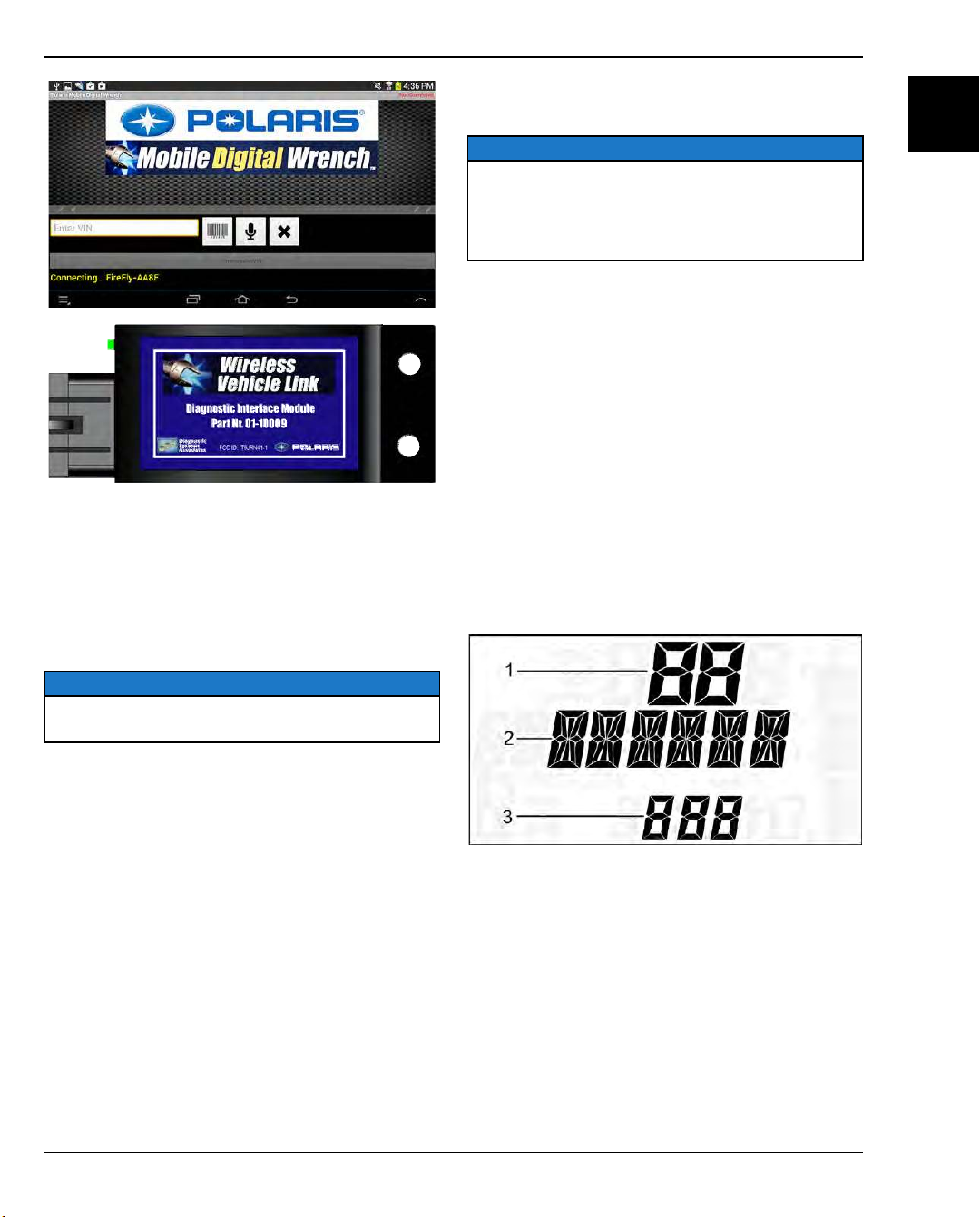
You can download the PMDW app on your Android
device from the Polaris dealer website. From the Service
and Warranty drop-down, select Digital Wrench, and
then click Mobile Digital Wrench App Download.
MINIMUM SPECIFICATIONS FOR ANDROID
DEVICES
• Minimum operating system: Android 3.1 “Honeycomb”
or higher (Android 4.0 or higher preferred)
NOTICE
The PMDW app will not work on Microsoft Windows 8™
or Apple IOS™ products.
GENERAL INFORMATION
ENGINE ELECTRICAL DIAGNOSTICS
DIAGNOSTIC TROUBLE CODES OVERVIEW
NOTICE
The diagnostic mode is accessible only when the check
engine MIL has been activated.
If there is a diagnostic problem with the power steering
system, the power steering MIL will illuminate and blink
in place of the check engine MIL.
Use the following procedure to display diagnostic trouble
codes that were activated during current ignition cycle
causing the MIL to illuminate. Error codes are not stored.
When the key is turned OFF, the code and message is
lost, but will reappear if the fault reoccurs after restarting
the engine.
If the CHECK ENGINE lamp or the EPAS lamp
illuminates, retrieve the active error codes from the
display.
1. Press and hold the MODE button to enter the settings
menu.
2. Press either toggle button to cycle to the
“DIAGCODE” option. Press MODE to select.
3. More than one diagnostic code may be present.
Press the toggle UP button to see if more codes are
present. Press MODE to select a code.
4. Record the three numbers displayed.
1
• Dual core processor / 2 GB internal memory / external
micro SD (32 or 64 GB) slot / 500 MB RAM
• Rear facing camera with minimum 3.0 mega pixel
resolution with auto / continuous focus
• Video, microphone, and voice-to-text capable
• Internet and Bluetooth wireless technology capable
• Device must be set to allow the installation of nonmarket applications
ADDITIONAL INFORMATION
• An electronic user’s guide is provided within the
PMDW app. To access the user’s guide, launch the
app, and then click “Help” under the Settings /
Preferences menu.
• Only CAN-based vehicles are compatible with the
PMDW app and the WVL. See the user’s guide for a
complete list of compatible vehicles.
9850043 R01 - 2017-2021 RANGER 500 / 570 Service Manual
© Copyright Polaris Inc.
• The first number (located top) can be 1 to 2 digits in
length. This number equates to the fault mode
(FMI).
• The second number (located middle) can be 2 to 6
digits in length. This number equates to the
suspected area of fault (SPN).
• The third number (located bottom) can range from
0 to 9. This number represents the total number of
trouble code present (example: 2 means there are
3 codes present).
5. Press MODE to exit to the settings menu.
1.75
Page 84

GENERAL INFORMATION
MASTER TROUBLE CODE LIST
IMPORTANT
Not all codes that are listed in this chart will be applicable to all vehicles. For vehicle specific codes, and pin-point
testing. Please refer to Digital Wrench for more information.
SPN COMPONENT
29 Accelerator Position 2
51 Throttle Position Sensor 1
70
84
91 Accelerator Position 1
96
98
100
102 Manifold Absolute Pressure Sensor
Parking Brake Switch
Vehicle Speed Sensor
Fuel Level Signal
Engine Oil Level Sensor/Switch
Engine Oil Pressure
FMI CONDITION CODE
0 Data Valid But Above Normal Operational Range P350A
2 Not Plausible P1225
3 Voltage Too High P1228
4 Voltage Too Low P1227
0 Data Valid But Above Normal Operational Range P1123
1 Data Valid But Below Normal Operational Range P1122
2 Signal Out of Range P0121
3 Voltage Too High P0123
4 Voltage Too Low P0122
10 Abnormal Rate Of Change P0120
13 Out Of Calibration P1120
19 Received Network Data In Error U25CD
0 Data Valid But Above Normal Operational Range P0500 / C1704 / C1057
1 Data Valid But Below Normal Operational Range P0502
2 Data Erratic or Intermittent (or missing) P0503 / C1058
3 Voltage Too High P1507
4 Voltage Below Normal, Or Shorted To Low Source P1506
8 Abnormal Frequency Or Pulse Width Or Period P0501
9 Abnormal Update Rate P160A
10 Abnormal Rate Of Change C1068 / C1705
12 Bad Intelligent Device Or Component P3503
19 Received Vehicle Speed Has Error P106B / C1069 / P306B
3 Voltage Too High P0228
4 Voltage Too Low P0227
2 Data Erratic, Intermittent Or Incorrect P0461
3 Voltage Above Normal, Or Shorted To High Source P0463
4 Voltage Too Low P0462
16 Data Valid But Above Normal Operating Range P1462
18 Data Valid But Below Normal Operating Range P1463
3 Voltage Above Normal, Or Shorted To High Source P1527
4 Voltage Too Low P1526
17 Data Valid But Below Normal Operating Range - Least Severe Level P250F
1 Data Valid But Below Normal Operational Range - Most Severe Level P1524
2 Data Erratic, Intermittent Or Incorrect P3021
5 Current Below Normal Or Open Circuit P1521
12 Bad Intelligent Device Or Component P3020
17 Data Valid But Below Normal Operating Range - Least Severe Level P0524
18 Data Valid But Below Normal Operating Range - Moderately Severe
Level
2 Data Erratic, Intermittent Or Incorrect P0106
3 Voltage Above Normal, Or Shorted To High Source P0108
4 Voltage Too Low P0107
7 Mechanical System Not Responding Or Out Of Adjustment P1106
P1523
1.76
9850043 R01 - 2017-2021 RANGER 500 / 570 Service Manual
© Copyright Polaris Inc.
Page 85

GENERAL INFORMATION
SPN COMPONENT
Intake Air Temperature Sensor (T-
105
106 Intake Air Pressure Sensor
107
108 Barometric Pressure Sensor
110
157 Fuel Rail Pressure Sensor
158
162
167
Engine Air Filter 1 Differential
Engine Temperature Sensor
Alternator Power Supply Potential
MAP)
Pressure Sensor
Battery Potential
Transmission Range
FMI CONDITION CODE
10 Abnormal Rate Of Change P0109
0 Data Valid But Above Normal Operational Range - Most Severe Level P1111
2 Data Erratic, Intermittent Or Incorrect P0111
3 Voltage Too High P0113
4 Voltage Too Low P0112
10 Abnormal Rate Of Change P0114
15 Data Valid But Above Normal Operating Range P0127
0 Data Valid But Above Normal Operational Range P110B
1 Data Valid But Below Normal Operational Range P110A
2 Data Erratic, Intermittent Or Incorrect P1109
3 Voltage Too High P1108
4 Voltage Too Low P1107
0 Data Valid But Above Normal Operational Range - Most Severe Level P1280
2 Data Erratic, Intermittent Or Incorrect P1284
3 Voltage Above Normal, Or Shorted To High Source P1282
4 Voltage Too Low P1283
7 Mechanical System Not Responding Or Out Of Adjustment P1286
10 Abnormal Rate Of Change P1285
16 Data Valid But Above Normal Operating Range - Moderately Severe
Level
2 Data Erratic, Intermittent Or Incorrect P2227
3 Voltage Above Normal, Or Shorted To High Source P2229
4 Voltage Below Normal, Or Shorted To Low Source P2228
10 Abnormal Rate Of Change P2230
0 Engine Overheat Shutdown P1217
2 Data Erratic, Intermittent Or Incorrect P0116
3 Voltage Too High P0118
4 Voltage Too Low P0117
10 Abnormal Rate Of Change P0119
15 Data Valid But Above Normal Operating Range P1116
16 Temperature Too High P0217
17 Data Valid But Below Normal Operating Range P0128
19 Received Network Data In Error U25C6
2 Data Erratic, Intermittent Or Incorrect P0194
3 Voltage Above Normal, Or Shorted To High Source P0193
4 Voltage Below Normal, Or Shorted To Low Source P0192
5 Current Below Normal Or Open Circuit P0197
15 Data Valid But Above Normal Operating Range - Least Severe Level P0199
17 Data Valid But Below Normal Operating Range - Least Severe Level P0195
3 Voltage Above Normal, Or Shorted To High Source P1567
4 Voltage Below Normal, Or Shorted To Low Source P1566
2 Invalid U108D
0 Data Valid But Above Normal Operational Range - Most Severe Level P1570
1 Data Valid But Below Normal Operational Range - Most Severe Level P1572
3 Voltage Above Normal, Or Shorted To High Source P1569
4 Voltage Below Normal, Or Shorted To Low Source P1568
16 Data Valid But Above Normal Operating Range - Moderately Severe
Level
18 Data Valid But Below Normal Operating Range - Moderately Severe
Level
P1281
P1571
P1573
1
9850043 R01 - 2017-2021 RANGER 500 / 570 Service Manual
© Copyright Polaris Inc.
1.77
Page 86
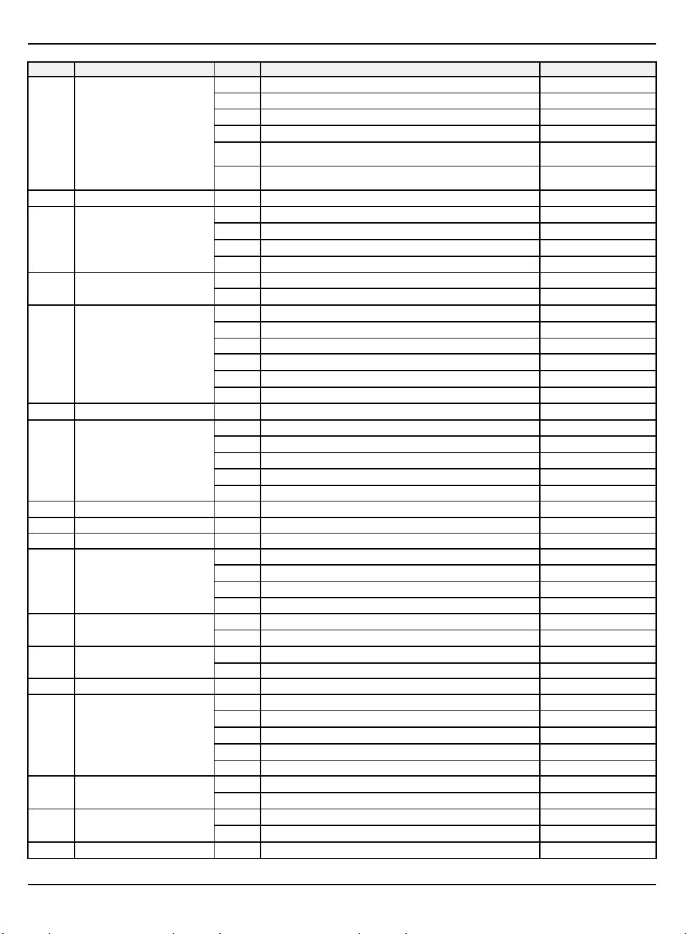
GENERAL INFORMATION
SPN COMPONENT
168
171
173
175
190
400
523
525
527 Cruise Control Panel Switches
563 ABS active
597 Brake Switch
627
628
630 Calibration 19 Checksum/CRC Error C1074
634 Idle Air Control
636 Crankshaft Position Sensor
637 Camshaft Position Sensor
645 Tachometer Driver Circuit
System Power
Ambient Air Temperature
Exhaust Temperature Sensor
Oil Temperature Sensor
Engine Speed
Engine Speed
Gear Sensor Signal
Transmission Requested Gear
System Voltage
ECU Memory
FMI CONDITION CODE
1 Data Valid But Below Normal Operational Range - Most Severe Level P1563
2 Data Erratic, Intermittent Or Incorrect P0561
3 Voltage Too High C1063 / P0563 / C1820
4 Voltage Too Low P0562
16 Data Valid But Above Normal Operating Range - Moderately Severe
Level
18 Data Valid But Below Normal Operating Range - Moderately Severe
Level
19 Received Network Data In Error U25C7
0 Data Valid But Above Normal Operational Range - Most Severe Level P1517
3 Voltage Above Normal, Or Shorted To High Source P0546
4 Voltage Below Normal, Or Shorted To Low Source P0545
10 Abnormal Rate Of Change P1546
2 Data Erratic, Intermittent Or Incorrect P3096
12 Bad Intelligent Device Or Component P3097
0 Data Valid But Above Normal Operational Range - Most Severe Level P0219 / C1059
1 Data Valid But Below Normal Operational Range - Most Severe Level C1060
2 Data Erratic, Intermittent Or Incorrect C1061
7 Mechanical System Not Responding Or Out Of Adjustment P1219
19 Received Engine Speed Has Error P3219 / C1066
31 Error in Engine Speed Computation P121C
Error in Engine Speed Computation
31
2 Data Erratic, Intermittent Or Incorrect P0914
3 Voltage Above Normal, Or Shorted To High Source P0917
4 Voltage Too Low P0916
9 Abnormal Update Rate P1914
11 Root Cause Not Known P0915
19 Received Network Data In Error U255C
31 Condition Exists P153D
19 Received Network Data In Error U25C9
2 Data Erratic, Intermittent Or Incorrect C0040
9 Abnormal Update Rate C1240
10 Abnormal Rate Of Change C2453
19 Received Network Data In Error C1340
15 Data Valid But Above Normal Operating Range - Least Severe Level P2504
17 Data Valid But Below Normal Operating Range - Least Severe Level P2503
12 Bad Intelligent Device Or Component P1602 / C1073
13 Out Of Calibration P0601 / C1601
3 Voltage Above Normal, Or Shorted To High Source P0509
4 Voltage Below Normal, Or Shorted To Low Source P0508
5 Current Below Normal Or Open Circuit P0505
7 Mechanical System Not Responding Or Out Of Adjustment P0519
13 Out Of Calibration P1300
2 Plausibility Fault P0335
8 Abnormal Frequency Or Pulse Width Or Period P0336
7 Mechanical System Not Responding Or Out Of Adjustment P0016
8 Abnormal Frequency Or Pulse Width Or Period P0340
3 Voltage Above Normal, Or Shorted To High Source P1739
P1564
P1565
P121D
1.78
9850043 R01 - 2017-2021 RANGER 500 / 570 Service Manual
© Copyright Polaris Inc.
Page 87

GENERAL INFORMATION
SPN COMPONENT
651
652
677 Starter Solenoid Driver Circuit
731 Knock Sensor 1
746
876
905
906
907
Injector 1 (MAG)
Injector 2 (PTO)
Rear Differential Output (Turf)
AC Compressor Clutch Relay
Wheel Speed Sensor (Front Left)
Wheel Speed Sensor (Front Right)
Wheel Speed Sensor (Rear or
Rear Left)
FMI CONDITION CODE
4 Voltage Below Normal, Or Shorted To Low Source P1738
5 Current Below Normal Or Open Circuit P1737
4 Voltage Below Normal / Shorted To Low Source / Driver Circuit
Grounded.
5 Current Below Normal / Open Circuit / Driver Circuit Open / Grounded P0261
3 Voltage Above Normal, Or Shorted To High Source / Driver Circuit Short
to B+
4 Voltage Below Normal, Or Shorted To Low Source / Driver Circuit
Grounded
5 Current Below Normal Or Open Circuit / Driver Circuit Open / Grounded P0264
3 Voltage Above Normal, Or Shorted To High Source P0617
4 Voltage Below Normal, Or Shorted To Low Source P0616
5 Current Below Normal Or Open Circuit P0615
1 Data Valid But Below Normal Operational Range - Most Severe Level P0326
2 Data Erratic, Intermittent Or Incorrect P0325
3 Voltage Above Normal, Or Shorted To High Source P0328
4 Voltage Below Normal, Or Shorted To Low Source P0327
3 Driver Circuit Short to B+ P1692
4 Driver Circuit Grounded P1693
5 Driver Circuit Open / Grounded P1691
3 Voltage Above Normal, Or Shorted To High Source P0647
4 Voltage Below Normal, Or Shorted To Low Source P0646
5 Current Below Normal Or Open Circuit P0645
2 Data Erratic, Intermittent Or Incorrect C1131
3 Voltage Above Normal, Or Shorted To High Source C1231
4 Voltage Below Normal, Or Shorted To Low Source C1331
5 Current Below Normal Or Open Circuit C1631
6 Current Above Normal Or Grounded Circuit C1B31
7 Mechanical System Not Responding Or Out Of Adjustment C1731
8 Abnormal Frequency Or Pulse Width Or Period C1431
10 Abnormal Rate Of Change C1831
14 Special Instructions C1531
20 Data Drifted High C1931
21 Data Drifted Low C1A31
31 Condition Exists C0032
2 Data Erratic, Intermittent Or Incorrect C1034
3 Voltage Above Normal, Or Shorted To High Source C1134
4 Voltage Below Normal, Or Shorted To Low Source C1234
5 Current Below Normal Or Open Circuit C1634
6 Current Above Normal Or Grounded Circuit C1B34
7 Mechanical System Not Responding Or Out Of Adjustment C1734
8 Abnormal Frequency Or Pulse Width Or Period C1334
10 Abnormal Rate Of Change C1834
14 Special Instructions C1434
20 Data Drifted High C1934
21 Data Drifted Low C1A34
31 Condition Exists C1C34
2 Data Erratic, Intermittent Or Incorrect C103D
3 Voltage Above Normal, Or Shorted To High Source C113D
4 Voltage Below Normal, Or Shorted To Low Source C123D
P1262
P0265
P1265
1
9850043 R01 - 2017-2021 RANGER 500 / 570 Service Manual
© Copyright Polaris Inc.
1.79
Page 88

GENERAL INFORMATION
SPN COMPONENT
Wheel Speed Sensor (Rear Right)
908
1071
1127 Boost Pressure Sensor
1268
1269
1321 Starter Enable Circuit
1347
1352
1353
1485
1557 Fan Driver 2
Fan Relay Driver Circuit
Ignition Coil Primary Driver 1
(MAG)
Ignition Coil Primary Driver 2 (PTO)
Fuel Pump Driver Circuit
Knock Level Cylinder 1 (MAG)
Knock Level Cylinder 2 (PTO)
EFI Relay Control Circuit
FMI CONDITION CODE
5 Current Below Normal Or Open Circuit C163D
6 Current Above Normal Or Grounded Circuit C1B3D
7 Mechanical System Not Responding Or Out Of Adjustment C173D
8 Abnormal Frequency Or Pulse Width Or Period C133D
10 Abnormal Rate Of Change C183D
11 Root Cause Not Known C2429
14 Special Instructions C143D
20 Data Drifted High C193D
21 Data Drifted Low C1A3D
31 Condition Exists C1C3D
2 Data Erratic, Intermittent Or Incorrect C1047
5 Current Below Normal Or Open Circuit C1647
6 Current Above Normal Or Grounded Circuit C1B47
7 Mechanical System Not Responding Or Out Of Adjustment C1747
10 Abnormal Rate Of Change C1847
20 Data Drifted High C1947
21 Data Drifted Low C1A47
31 Condition Exists C1C47
3 Voltage Above Normal P1482
4 Voltage Below Normal P1483
5 Current Below Normal Or Open Circuit P1481
0 Data Valid But Above Normal Operational Range P0234
2 Data Erratic, Intermittent Or Incorrect P0236
3 Voltage Above Normal P0238
4 Voltage Below Normal P0237
31 Condition Exists P1234
3 Voltage Above Normal P1353
4 Voltage Below Normal P1361
5 Current Below Normal Or Open Circuit P1351
3 Voltage Above Normal P1354
4 Voltage Below Normal P1362
5 Current Below Normal Or Open Circuit P1352
3 Voltage Above Normal P1617
4 Voltage Below Normal P1616
5 Current Below Normal Or Open Circuit P1615
3 Voltage Above Normal P0232
4 Voltage Below Normal P0231
5 Current Below Normal Or Open Circuit P0230
8 Abnormal Frequency Or Pulse Width Or Period P0233
0 Data Valid But Above Normal Operational Range P1336
16 Data Valid But Above Normal Operating Range P2336
0 Data Valid But Above Normal Operational Range P1337
16 Data Valid But Above Normal Operating Range P2337
3 Voltage Above Normal P0687
4 Voltage Below Normal P0686
5 Current Below Normal Or Open Circuit P0685
3 Voltage Above Normal P0694
4 Voltage Below Normal, Or Shorted To Low Source P0693
1.80
9850043 R01 - 2017-2021 RANGER 500 / 570 Service Manual
© Copyright Polaris Inc.
Page 89

GENERAL INFORMATION
SPN COMPONENT
1809 Lateral Acceleration Sensor
Longitudinal Acceleration Sensor
1810
1888 PTO Solenoid Driver Circuit
2584 Brake Pressure Switches
2590
2596
2629
3056
3057
3597
3598
3599
Vehicle Speed
Speed Key Selected Maximum
Vehicle Speed Limit Message
Engine Turbocharger 1
Compressor Outlet Temperature
Oxygen Sensor Bank 1 Sensor 1
Oxygen Sensor Bank 1 Sensor 2
ECU Output Supply Voltage 1
ECU Output Supply Voltage 2
ECU Output Supply Voltage 3
FMI CONDITION CODE
5 Current Below Normal Or Open Circuit P0481
13 Out Of Calibration C1261
19 Received Network Data In Error U25CA
20 Data Drifted High C1161
7 Mechanical System Not Responding Or Out Of Adjustment C1362
13 Out Of Calibration C1262
19 Received Network Data In Error U25CB
20 Data Drifted High C1162
3 Voltage Above Normal, Or Shorted To High Source P1311
4 Voltage Below Normal, Or Shorted To Low Source P1312
5 Current Below Normal Or Open Circuit P1310
3 Voltage Above Normal, Or Shorted To High Source C2244
4 Voltage Below Normal, Or Shorted To Low Source C2044
13 Out Of Calibration C1263
17 Data Valid But Below Normal Operating Range - Least Severe Level C2144
20 Data Drifted High C1164
16 Data Valid But Above Normal Operating Range - Moderately Severe
Level
19 Received Network Data In Error U255A
31 Condition Exists U2259
3 Voltage Above Normal, Or Shorted To High Source P1235
4 Voltage Below Normal, Or Shorted To Low Source P1236
2 Data Erratic, Intermittent Or Incorrect P0130
3 Voltage Above Normal, Or Shorted To High Source P0132
4 Voltage Below Normal, Or Shorted To Low Source P0131 / C1049
12 Bad Intelligent Device Or Component P113A
17 Data Valid But Below Normal Operating Range - Least Severe Level C2049
2 Data Erratic, Intermittent Or Incorrect P0136
3 Voltage Above Normal, Or Shorted To High Source P0138
4 Voltage Below Normal, Or Shorted To Low Source P0137
0 Data Valid But Above Normal Operational Range - Most Severe Level P16A3
1 Data Valid But Below Normal Operational Range - Most Severe Level P16A6
3 Voltage Above Normal, Or Shorted To High Source P16A2
4 Voltage Below Normal, Or Shorted To Low Source P16A1
16 Data Valid But Above Normal Operating Range - Moderately Severe
Level
18 Data Valid But Below Normal Operating Range - Moderately Severe
Level
0 Data Valid But Above Normal Operational Range - Most Severe Level P16AA
1 Data Valid But Below Normal Operational Range - Most Severe Level P16AC
3 Voltage Above Normal, Or Shorted To High Source P16A9
4 Voltage Below Normal, Or Shorted To Low Source P16A8
16 Data Valid But Above Normal Operating Range - Moderately Severe
Level
18 Data Valid But Below Normal Operating Range - Moderately Severe
Level
0 Data Valid But Above Normal Operational Range - Most Severe Level P17AC
1 Data Valid But Below Normal Operational Range - Most Severe Level P17AE
3 Voltage Above Normal, Or Shorted To High Source P17AA
4 Voltage Below Normal, Or Shorted To Low Source P17AB
P1500
P16A5
P16A7
P16AB
P16AD
1
9850043 R01 - 2017-2021 RANGER 500 / 570 Service Manual
© Copyright Polaris Inc.
1.81
Page 90

GENERAL INFORMATION
SPN COMPONENT
8014
65559 CAN1 Bus Hardware
65613
516125 CAN 1
516178
520129 ABS Low Pressure Feed Circuit 1
520130 ABS Low Pressure Feed Circuit 2
520131
520132
520133 ABS Internal Pressure Sensor
520134
520137
520140 ABS Internal ECU Failure
520141
520152
520153
520194
520198 Throttle Position Sensor 2
520201
520202
520203
520204 Fuel Correction Front
520205 Fuel Correction Rear
520206 Reverse Alarm
Battery Charger
ETC Accelerator Position Sensor
Correlation
Idle Engine speed
ABS Valve Relay
ABS Pressure Sensor Supply Out
Front Wheel Back Drive (Active
of Range
ABS Motor Supply Failure
ABS Manually Disabled
CAN1 Bus Wiring
ABS Solenoid (Rear Left In)
ABS Solenoid (Rear Left Out)
Throttle Release Signal
Overheat Indicator Lamp
Canister Purge Valve
Descent System)
FMI CONDITION CODE
16 Data Valid But Above Normal Operating Range - Moderately Severe
Level
18 Data Valid But Below Normal Operating Range - Moderately Severe
Level
18 Data Valid But Below Normal Operating Range - Moderately Severe
Level
31 Condition Exists P0762
11 Root Cause Not Known P1130 / U2101
31 Condition Exists C1130
2 Data Erratic, Intermittent Or Incorrect P1135
9 Abnormal Update Rate U25E9
19 Received Network Data In Error U25C0
31 Condition Exists C1012
31 Condition Exists C1013
12 Bad Intelligent Device Or Component C2420
31 Condition Exists C2423
2 Data Erratic, Intermittent Or Incorrect C2439
12 Bad Intelligent Device Or Component C2424
31 Condition Exists C2425
31 Condition Exists C2433
12 Bad Intelligent Device Or Component C2437
31 Condition Exists C2438
31 Condition Exists C1324
31 Condition Exists C1325
2 Data Erratic, Intermittent Or Incorrect P1553
3 Voltage Above Normal, Or Shorted To High Source P1555
4 Voltage Below Normal, Or Shorted To Low Source P1554
7 Mechanical System Not Responding Or Out Of Adjustment P1552
0 Data Valid But Above Normal Operational Range - Most Severe Level P1223
1 Data Valid But Below Normal Operational Range - Most Severe Level P1222
3 Voltage Above Normal, Or Shorted To High Source P0223
4 Voltage Below Normal, Or Shorted To Low Source P0222
10 Abnormal Rate Of Change P0220
13 Out Of Calibration P1220
3 Voltage Above Normal, Or Shorted To High Source P1656
4 Voltage Below Normal, Or Shorted To Low Source P1657
5 Current Below Normal Or Open Circuit P1655
3 Voltage Above Normal, Or Shorted To High Source P0443
4 Voltage Below Normal, Or Shorted To Low Source P0445
5 Current Below Normal Or Open Circuit P0444
3 Voltage Above Normal, Or Shorted To High Source P1686
4 Voltage Below Normal, Or Shorted To Low Source P1687
5 Current Below Normal Or Open Circuit P1685
15 Data Valid But Above Normal Operating Range - Least Severe Level P0172
17 Data Valid But Below Normal Operating Range - Least Severe Level P0171
15 Data Valid But Above Normal Operating Range - Least Severe Level P0175
17 Data Valid But Below Normal Operating Range - Least Severe Level P0174
2 Data Erratic, Intermittent Or Incorrect P1684
3 Voltage Above Normal, Or Shorted To High Source P1682
P17AD
P17AF
P0761
1.82
9850043 R01 - 2017-2021 RANGER 500 / 570 Service Manual
© Copyright Polaris Inc.
Page 91

GENERAL INFORMATION
SPN COMPONENT
520207 All Wheel Drive Control Circuit
520208
520211
520219
520220
520221
520222
520223
520224
520225
520226
520227
520228 Position Encoder Error
520229 Software Error
520230 IC CAN Communication with EPS
520231 EPS Power Save Condition
520252
520253
520254
520255
520256
520257
520260 ABS Motor
Chassis Relay
Idle Speed
Accessory Relay
Battery Charge Relay
Steering Over Current Shut Down
Steering Excessive Current Error
Steering Torque Partial Failure
Steering Torque Full Failure
EPS Inverter Temperature
EPS Communications Receive
Data Error
EPS CAN Communications
Transmit Error
ABS Solenoid (Rear or Right Rear
ABS Solenoid (Rear or Right Rear
ABS Solenoid (Front or Front Left
ABS Solenoid (Front or Front Left
ABS Solenoid (Front Right In)
ABS Solenoid (Front Right Out)
In)
Out)
In)
Out)
FMI CONDITION CODE
4 Voltage Below Normal, Or Shorted To Low Source P1683
5 Current Below Normal Or Open Circuit P1681
3 Voltage Above Normal, Or Shorted To High Source P1835
4 Voltage Below Normal, Or Shorted To Low Source P1834
5 Current Below Normal Or Open Circuit P1836
3 Voltage Above Normal, Or Shorted To High Source P1614
4 Voltage Below Normal, Or Shorted To Low Source P1613
5 Current Below Normal Or Open Circuit P1611
3 Voltage Above Normal, Or Shorted To High Source P0507
4 Voltage Below Normal, Or Shorted To Low Source P0506
3 Voltage Above Normal, Or Shorted To High Source P1647
4 Voltage Below Normal, Or Shorted To Low Source P1645
5 Current Below Normal Or Open Circuit P1646
3 Voltage Above Normal, Or Shorted To High Source P163D
4 Voltage Below Normal, Or Shorted To Low Source P163A
5 Current Below Normal Or Open Circuit P163C
6 Current Above Normal Or Grounded Circuit C1050
12 Bad Intelligent Device Or Component C102E
6 Current Above Normal Or Grounded Circuit C1051
31 Condition Exists C1052
31 Condition Exists C1053
0 Data Valid But Above Normal Operational Range - Most Severe Level C1055
12 Bad Intelligent Device Or Component C102F
16 Data Valid But Above Normal Operating Range - Moderately Severe
Level
2 Data Erratic, Intermittent Or Incorrect U0100
31 Condition Exists C1067
2 Data Erratic, Intermittent Or Incorrect U1100
11 Root Cause Not Known C1065
12 Bad Intelligent Device Or Component C106A
31 Condition Exists C106B
12 Bad Intelligent Device Or Component C1070
31 Condition Exists C106F
31 Condition Exists U0131
31 Condition Exists C1071
5 Current Below Normal Or Open Circuit C1024
31 Condition Exists C1330
5 Current Below Normal Or Open Circuit C1025
31 Condition Exists C1332
5 Current Below Normal Or Open Circuit C1026
31 Condition Exists C1326
5 Current Below Normal Or Open Circuit C1027
31 Condition Exists C1327
5 Current Below Normal Or Open Circuit C1028
31 Condition Exists C1328
5 Current Below Normal Or Open Circuit C1029
31 Condition Exists C1329
3 Voltage Above Normal, Or Shorted To High Source C1020
C1054
1
9850043 R01 - 2017-2021 RANGER 500 / 570 Service Manual
© Copyright Polaris Inc.
1.83
Page 92

GENERAL INFORMATION
SPN COMPONENT
520262
520264 ABS/Brake Controller ECU
520265 ABS Module
520266
520272
520273
520275
520276
520277
520278
520279
520280
520281
520282
520283
520284
520285
520286
520287
520288
520289
ABS/Brake Controller Source
Voltage
ABS Brake Switch (Front/Rear)
Glow Plug Relay Driver Circuit
Fuel Pull Solenoid Relay Driver
Circuit (Low Side)
Accelerator Position/Brake Position
Throttle Body Control - Limp Home
Throttle Body Control - Mechanical
Throttle Body Control - Repeated
ECU Monitoring of Injection Cut Off
ECU Monitoring of Injection Cut Off
Interaction
Throttle Position Sensor (1 or 2
Indeterminable)
Throttle Body Control - Power
Throttle Body Control - Return
Throttle Body Control - Adaption
Throttle Body Control - Position
ECU Monitoring Error (Level 3)
Stage
Spring Check Failed
Aborted
Position Check Failed
Stop Adaptation Failure
Adaptation Failed
Throttle Body Control
Deviation Fault
Brake Switch (1 or 2
Indeterminable)
ECU Monitoring Error
(Level 1)
(Level 2)
FMI CONDITION CODE
4 Voltage Below Normal, Or Shorted To Low Source C1021
6 Current Above Normal Or Grounded Circuit C101E
7 Mechanical System Not Responding Or Out Of Adjustment C0020
8 Abnormal Frequency Or Pulse Width Or Period C101F
12 Bad Intelligent Device Or Component C101C
0 Data Valid But Above Normal Operational Range - Most Severe Level C2422
1 Data Valid But Below Normal Operational Range - Most Severe Level C2421
3 Voltage Above Normal, Or Shorted To High Source C1039 / C1241
4 Voltage Below Normal, Or Shorted To Low Source C1038
12 Bad Intelligent Device Or Component C1041
12 Bad Intelligent Device Or Component C1243
13 Out Of Calibration C1141
7 Mechanical System Not Responding Or Out Of Adjustment C1042
3 Voltage Above Normal, Or Shorted To High Source C1044
5 Current Below Normal Or Open Circuit C1043
3 Voltage Above Normal, Or Shorted To High Source P1384
4 Voltage Below Normal, Or Shorted To Low Source P1383
5 Current Below Normal Or Open Circuit P1385
3 Voltage Above Normal, Or Shorted To High Source P125D
4 Voltage Below Normal, Or Shorted To Low Source P125C
5 Current Below Normal Or Open Circuit P125A
31 Condition Exists P150A / U1007
2 Data Erratic, Intermittent Or Incorrect P150C
12 Bad Intelligent Device Or Component P150B
2 Data Erratic, Intermittent Or Incorrect P151A
3 Voltage Above Normal, Or Shorted To High Source P150D
4 Voltage Below Normal, Or Shorted To Low Source P150E
8 Abnormal Frequency Or Pulse Width Or Period P151B
31 Condition Exists P153F
31 Condition Exists P151C
31 Condition Exists P151D
31 Condition Exists P151E
31 Condition Exists P152A
31 Condition Exists P152B
2 Data Erratic, Intermittent Or Incorrect P152F
3 Voltage Above Normal, Or Shorted To High Source P152C
4 Voltage Below Normal, Or Shorted To Low Source P152D
31 Condition Exists P152E
2 Data Erratic, Intermittent Or Incorrect P153E
31 Condition Exists P1540
31 Condition Exists P1541
31 Condition Exists P1542
31 Condition Exists P1543
1.84
9850043 R01 - 2017-2021 RANGER 500 / 570 Service Manual
© Copyright Polaris Inc.
Page 93

GENERAL INFORMATION
SPN COMPONENT
520305
520306 ECU ADC Fault - No Load
520307
520308
520309 ECU Fault - ICO
520311
520331 Knock Sensor Positive Line
520332
520341
520342 Idle Fuel Correction Bank 1
520343 Idle Fuel Correction Bank 2
520344
520376
520381
520496
520498 Stator
520513 Motor Controller Encoder
520514
520515
520516
520517 Motor Controller
520518 Motor Controller Contactor
520519
520520 BMC CAN Communication
520522
524067 Drive Mode Select Switch
524070
Throttle Body Control - Requested
Throttle Angle Not Plausible
ECU ADC Fault - Voltage
Accelerator Sensor Sync Fault -
Sensor Diff Exceeds Limit
ECU Fault - Hardware Disruption
Knock Sensor Negative Line
Wastegate Solenoid Driver
Adaptive Fuel Correction Bank 1
Internal fault - Chassis Output
Disabled
Non Functional Application SW
Intercooler Pump Driver Circuit
Motor Controller Speed Sensor
Installed
Motor Controller Temperature
Sensor
Electric Motor Temperature
Motor Controller Temperature
Display Relay
Operator Presence Switch
FMI CONDITION CODE
31 Condition Exists P1530
31 Condition Exists P1531
31 Condition Exists P1532
31 Condition Exists P1533
31 Condition Exists P1534
31 Condition Exists P1537
3 Voltage Above Normal, Or Shorted To High Source P1327
4 Voltage Below Normal, Or Shorted To Low Source P1328
3 Voltage Above Normal, Or Shorted To High Source P132A
4 Voltage Below Normal, Or Shorted To Low Source P132B
3 Voltage Above Normal, Or Shorted To High Source P0243
4 Voltage Below Normal, Or Shorted To Low Source P0246
5 Current Below Normal Or Open Circuit P0245
15 Data Valid But Above Normal Operating Range - Least Severe Level P116C
15 Data Valid But Above Normal Operating Range - Least Severe Level P116E
17 Data Valid But Below Normal Operating Range - Least Severe Level P116F
15 Data Valid But Above Normal Operating Range - Least Severe Level P0170
17 Data Valid But Below Normal Operating Range - Least Severe Level P1170
31 Condition Exists P1618
31 Condition Exists C1681
3 Voltage Above Normal, Or Shorted To High Source P107D
4 Voltage Below Normal, Or Shorted To Low Source P107C
5 Current Below Normal Or Open Circuit P107E
4 Voltage Below Normal, Or Shorted To Low Source P1510
5 Current Below Normal Or Open Circuit P1511
2 Data Erratic, Intermittent Or Incorrect P1140 / P1368
31 Condition Exists P1141 / P1369
3 Voltage Above Normal, Or Shorted To High Source P1142 / P1165
4 Voltage Below Normal, Or Shorted To Low Source P1143 / P1166
31 Condition Exists P1144 / P1167
0 Data Valid But Above Normal Operational Range - Most Severe Level P1145 / P1168
4 Voltage Below Normal, Or Shorted To Low Source P1B0D / P1169
0 Data Valid But Above Normal Operational Range - Most Severe Level P1146 / P116A
3 Voltage Above Normal, Or Shorted To High Source P1147 / P1184
6 Current Above Normal Or Grounded Circuit P1148 / P1185
12 Bad Intelligent Device Or Component P1149 / P1186
19 Received Network Data In Error P1150 / P1187
5 Current Below Normal Or Open Circuit P1151 / P1177
6 Current Above Normal Or Grounded Circuit P1152 / P1178
31 Condition Exists P1153 / P116B
31 Condition Exists P0754
5 Current Below Normal Or Open Circuit P3038
2 Data Erratic, Intermittent Or Incorrect P153C
3 Voltage Above Normal, Or Shorted To High Source P153A
4 Voltage Below Normal, Or Shorted To Low Source P153B
3 Voltage Above Normal, Or Shorted To High Source P251C
1
9850043 R01 - 2017-2021 RANGER 500 / 570 Service Manual
© Copyright Polaris Inc.
1.85
Page 94

GENERAL INFORMATION
SPN COMPONENT
524075
524076
524085
524086
Hydraulic Oil Pressure Sensor/
Engine Oil Pressure Sensor/Switch
EPS Fault Lamp Driver Circuit
Switch
EPS SEPIC Voltage Error
FMI CONDITION CODE
17 Data Valid But Below Normal Operating Range - Least Severe Level P150F
17 Data Valid But Below Normal Operating Range - Least Severe Level P151F
12 Bad Intelligent Device Or Component C106C
3 Voltage Above Normal, Or Shorted To High Source C106D
4 Voltage Below Normal, Or Shorted To Low Source C106E
1.86
9850043 R01 - 2017-2021 RANGER 500 / 570 Service Manual
© Copyright Polaris Inc.
Page 95

GENERAL INFORMATION
CYLINDER MISFIRE DETECTION
NOTICE
This process only applies to some MY15 and later
models.
Refer to this procedure only if one of the codes shown
below is displayed in Digital Wrench.
The ECU monitors crankshaft speed via the crankshaft
position sensor. A misfire will cause a fluctuation in
crankshaft speed. A code will set and turn on the check
engine light after an engine misfire threshold/rate is
detected that is above a pre-determined limit. This
threshold varies based on engine speed.
One or more of the following codes will be set if a misfire
occurs:
• P0301 (SPN 65591/FMI 7) Misfire Detected, Cylinder
1 (MAG)
• P0302 (SPN 65592/FMI 7) Misfire Detected, Cylinder
2 (PTO)
• P0314 (SPN 65590/FMI 7) Misfire Detected, Cylinder
Not Identified
Once a cylinder misfire code is set, the following events
will occur:
• Check Engine Light illuminates
• If the cylinder can be detected by the ECU (code
P0301 or P0302), the ECU will deactivate the fuel
injector for that cylinder. This will remain in effect until
the key is cycled off and back on.
• If the cylinder with the misfire cannot be detected
(code P0314), the ECU will limit available power by
limiting how far the throttle plate opens.
If a misfire code has been set and there is no observed
misfire, cycle the key and allow 4000 engine revolutions
to see if the check engine light turns off. If it does not turn
off, diagnose by verifying the following items:
• Low battery voltage (loose connection, low charge,
bad battery)
• Faulty voltage regulator
• Ignition Coil and connections are good
• Spark plugs wires are secure
• The correct spark plugs are installed and the plugs are
not fouled
• Crankshaft Position Sensor tests good
• Wiring to the Crankshaft Position Sensor, ECU and
Ignition Coil are not damaged. Chassis ground is clean
and tight
• Fuel pressure is within specification
• Fresh/good quality fuel is in the fuel tank
• Engine mechanical is good (leak down, timing)
• Confirm the belt is in good condition, specifically
looking for signs of hour-glassing
• Confirm primary clutch operation (worn/incorrect
weights, loose spider/jam nut)
• Confirm secondary clutch operation (sliders, rollers,
helix)
1
One the key is cycled, the trouble code(s) will show
current but there will be no fuel injector deactivation or
throttle limitation unless the misfiring continues to occur.
The check engine light will remain illuminated until there
are 4000 engine revolutions (i.e. 4000 RPM for one
minute) without a significant misfire being detected.
Once this condition is met, the check engine light will turn
off and the code(s) will show as historic.
9850043 R01 - 2017-2021 RANGER 500 / 570 Service Manual
© Copyright Polaris Inc.
1.87
Page 96

GENERAL INFORMATION
FLUID LEAKS
Fluid leaks can apply to multiple different systems used in the vehicle. Leaks can be a common cause of concerns
within these systems. Procedures that are used for checking leaks can apply to multiple systems.
When diagnosing fluid leaks, refer to the appropriate “Level Inspection” procedure, Fluid Inspection page 1.88, or the
appropriate chapter in the Service Manual before proceeding with any repairs or parts replacement.
FLUID INSPECTION
OVERVIEW
Multiple vehicle systems will contain different fluids or lubricants within the system.
These fluids should be inspected for condition and level. Refer to Fluid Condition and the appropriate level check
within the Service Manual for more information.
Most of these systems should be inspected for leaks using the same methods. Refer to Fluid Leak for more
information.
FLUID LEAK
Perform the following inspection prior to replacement of any seals or gaskets.
1. Inspect the fluid level prior to any checks to verify that the system is currently leaking.
NOTICE
If the system is not low at this time, clean and continue to monitor. It is possible that the fluid is residual from
2. Thoroughly clean the area using an appropriate cleaner (Brake cleaner, Throttle Body cleaner, Soap, etc.) prior to
diagnosing the leak.
3. Operate the vehicle under the condition that the leak presented and re-inspect for leak.
4. Pinpoint location of leak. Check for any damage to parts and repair the leak as necessary.
If the leak can not be pin-pointed using this method, the leak may require dye to be added to the system, operated
manufacturing or previous repairs.
NOTICE
and inspected for leaks using a UV light.
FLUID CONDITION
Refer to the appropriate “Level Check” procedure for the fluid being inspected. When the fluid is inspected it should
be compared to NEW recommended replacement fluid.
INSPECTION ITEMS CAUSE
Inspect for the following:
• Unusual Color
• Unusual Odor
• Fluid Contamination
1.88
• The fluid has been contaminated with another fluid
(cross-contamination, ex. Oil mixing with Coolant).
• Fluid overheated
• Natural fluid breakdown (replace fluid per
recommended maintenance interval / fluid
replacement procedure).
• If a fluid is contaminated with metal or debris, suspect
that there is a mechanical failure causing the fluid
contamination. Refer to the Service Manual
information related to the system in question.
9850043 R01 - 2017-2021 RANGER 500 / 570 Service Manual
© Copyright Polaris Inc.
Page 97

FUEL SYSTEM DIAGNOSTICS
FUEL SYSTEM TROUBLESHOOTING
FUEL STARVATION / LEAN MIXTURE
SYMPTOMS CAUSES
GENERAL INFORMATION
1
• Hard start or no start
• Bog
• Backfire
• Popping through Intake / Exhaust
• Hesitation
• Detonation
• Low Power
• Spark plug erosion / fouling
• Engine runs hot
• Surging
• High / Erratic idle
RICH MIXTURE
SYMPTOMS CAUSES
• Hard start or no start
• Bog
• Backfire
• Popping through Intake / Exhaust
• Hesitation
• Detonation
• Low Power
• Spark plug erosion / fouling
• Engine runs hot
• Surging
• High / Erratic idle
• No fuel in tank
• Restricted tank vent, or routed improperly
• Fuel lines or fuel injectors restricted
• Fuel filter plugged
• Fuel pump inoperative
• Air leak in system
• Intake air leak (throttle shaft, intake ducts, air box
cover)
• Faulty oxygen sensor
• No fuel in tank
• Restricted tank vent, or routed improperly
• Fuel lines or fuel injectors restricted
• Fuel filter plugged
• Fuel pump inoperative
• Air leak in system
• Intake air leak (throttle shaft, intake ducts, air box
cover)
• Faulty oxygen sensor
9850043 R01 - 2017-2021 RANGER 500 / 570 Service Manual
© Copyright Polaris Inc.
1.89
Page 98

GENERAL INFORMATION
POOR IDLE
SYMPTOMS CAUSES
• Idle Too High (if > 1400 RPM when warm).
• Throttle stop screw tampering
• Throttle cable sticking, improperly adjusted, routed
incorrectly
• Faulty electrical connection
• Idle Too Low (if < 1100 RPM when warm). • Plugged air filter
• Leaking injector (rich condition)
• Belt dragging
• Throttle stop screw tampering
• Erratic Idle • Throttle cable incorrectly adjusted
• Air Leaks, dirty injector
• TMAP damaged (check with Digital Wrench®)
• Tight valves (low compression or high leakdown)
• Ignition timing incorrect
• Belt dragging
• Dirty air filter
• High percentage of cylinder leakdown (worn engine)
• Low compression (worn engine)
• Spark plug(s) fouled
• Spark plug wires loose or worn
• Faulty electrical connection
1.90
9850043 R01 - 2017-2021 RANGER 500 / 570 Service Manual
© Copyright Polaris Inc.
Page 99

PVT SYSTEM DIAGNOSTICS
PVT SYSTEM TROUBLESHOOTING
SITUATION PROBABLE CAUSE REMEDY
Engine RPM
below specified
operating range,
although engine
is properly tuned.
Erratic engine
operating RPM
during
acceleration or
load variations.
Engine RPM
above specified
operating range.
Harsh drive clutch
engagement.
Drive belt turns
over
Belt burnt, thin
spots
Wrong or broken drive clutch spring. Replace with recommended spring.
Drive clutch shift weight too heavy.
Driven clutch spring broken or installed in
wrong helix location.
Drive clutch binding.
Belt worn unevenly - thin / burnt spots.
Driven clutch malfunction.
Sheave face grooved.
Incorrect drive clutch spring (too high of
rate).
Drive clutch shift weights incorrect for
application (too light).
Drive clutch binding.
Driven clutch binding.
Converter sheaves greasy; belt slipage. Clean sheaves with denatured alcohol or brake
Drive belt worn too narrow. Replace belt.
Excessive belt / sheave clearance with new
belt.
Wrong belt for application. Replace with correct belt.
Abuse (continued throttle application when
vehicle is stationary, excess load)
Dragging brake Inspect brake system.
Slow, easy clutch engagement Fast, effective use of throttle for efficient
Install correct shift weight kit to match engine
application.
Replace spring; refer to proper installation
location.
Disassemble drive clutch; inspect shift weights
for wear and free operation.
Clean and polish stationary shaft hub;
reassemble clutch without spring to determine
problem area.
Replace belt.
Replace ramp buttons.
Inspect movable sheave for excessive bushing
clearance.
Replace the clutch.
Install correct recommended spring.
Install correct recommended shift weights.
Disassemble and clean clutch, inspecting shift
weights and rollers. Reassemble without the
spring and move sheaves through entire range
to further determine probable cause.
Disassemble, clean, and inspect driven clutch,
noting worn sheave bushing and ramp buttons
and helix spring location.
cleaner, install new belt.
Perform belt / sheave clearance adjustment with
shim washers beneath spider.
Caution operator to operate machine within
guidelines.
engagement.
GENERAL INFORMATION
1
9850043 R01 - 2017-2021 RANGER 500 / 570 Service Manual
© Copyright Polaris Inc.
1.91
Page 100

GENERAL INFORMATION
SITUATION PROBABLE CAUSE REMEDY
PVT cover
overheating
(melting)
Water ingestion
Belt slippage
PVT noise
Engagement
erratic or stabby
Plugged air intake or outlet.
Belt slippage due to water, oil, grease, etc.,
rubbing on cover.
Clutches or weight being applied to cover
while in operation.
High vs. low range.
Cover seals or ducts leaking
Operator error
Belt worn out
Water ingestion Inspect and seal PVT system.
Belt contaminated with oil or grease Inspect and clean.
Belt worn or separated, thin spots, loose belt Replace belt.
Broken or worn clutch components, cover
hitting clutches
Thin spots on belt, worn belt
Drive clutch bushings stick Inspect and repair clutches.
Clear obstruction
Inspect system. Clean , repair or replace as
necessary. Seal PVT system ducts.
Remove weight. Inform operator.
Instruct operator on guidelines for operation in
proper driving range for different terrain as
outlined in Owner’s Safety and Maintenance
Manual.
Find leak and repair as necessary.
Instruct operator on guidelines for operation in
wet terrain as outlined in Owner’s Safety and
Maintenance Manual.
Replace belt.
Inspect and repair as necessary.
Replace belt. Refer to belt burnt troubleshooting
and instruct operator.
1.92
9850043 R01 - 2017-2021 RANGER 500 / 570 Service Manual
© Copyright Polaris Inc.
 Loading...