

Page 1
2018
OWNER’S MANUAL
RANGER® 1000 Diesel
RANGER® 1000 Diesel EPS
RANGER CREW® 1000 Diesel
Page 2
WARNING
Read, understand, and follow all of the instructions
and safety precautions in this manual and on all product labels.
Failure to follow the safety precautions could result in serious injury or death.
WARNING
The engine exhaust from this product contains chemicals known to the State
of California to cause cancer, birth defects or other reproductive harm.
For videos and more information
about a safe riding experience with
your Polaris vehicle, scan this QR
code with your smartphone.
Page 3

1
WELCOME
Thank you for purchasing a POLARIS vehicle, and welcome to our world-wide family of
POLARIS enthusiasts. Be sure to visit us online at www.polaris.com for the latest news, new
product introductions, upcoming events, career opportunities and more.
We believe POLARIS sets a standard of excellence for all utility and recreational vehicles
manufactured in the world today. Many years of experience have gone into the engineering,
design, and development of your POLARIS vehicle, making it the finest machine we’ve ever
produced.
For safe and enjoyable operation of your vehicle, be sure to follow the instructions and
recommendations in this owner’s manual.
Your manual contains instructions for minor maintenance, but information about major
repairs is outlined in the POLARIS Service Manual and can be performed by a factory
certified Master Service Dealer® (MSD) Technician.
Your POLARIS dealer knows your vehicle best and is interested in your total satisfaction.
Your POLARIS dealership can provide for all of your service needs during, and after, the
warranty period.
• Snowmobiles • RZR® sport vehicles
• All-terrain vehicles (ATVs) • GEM® electric vehicles
• Low emission vehicles (LEVs) • VICTORY® motorcycles
• RANGER® utility vehicles • INDIAN® motorcycles
•BRUTUS® work vehicles • POLARIS POWER® generators
• SLINGSHOT® three wheel motorcycles • POLARIS DEFENSE® combat vehicles
Page 4

2
POLARIS®, RANGER® and RANGER CREW® are trademarks of POLARIS Industries Inc.
Copyright 2017 POLARIS Industries Inc. All information contained within this publication is based on the latest
product information at the time of publication. Due to constant improvements in the design and quality of
production components, some minor discrepancies may result between the actual vehicle and the information
presented in this publication. Depictions and/or procedures in this publication are intended for reference use only.
No liability can be accepted for omissions or inaccuracies. Any reprinting or reuse of the depictions and/or
procedures contained within, whether whole or in part, is expressly prohibited.
The original instructions for this vehicle are in English. Other languages are provided as translations of the
original instructions.
Printed in U.S.A.
2018 RANGER Diesel / RANGER CREW Diesel Owner’s Manual
P/N 9928298
Page 5

3
TABLE OF CONTENTS
Introduction . . . . . . . . . . . . . . . . . . . . . . . . . . . . . . . . . . . . . . . . 4
Safety . . . . . . . . . . . . . . . . . . . . . . . . . . . . . . . . . . . . . . . . . . . . . 8
Features and Controls. . . . . . . . . . . . . . . . . . . . . . . . . . . . . . . 21
Operation . . . . . . . . . . . . . . . . . . . . . . . . . . . . . . . . . . . . . . . . . 35
Winch Guide . . . . . . . . . . . . . . . . . . . . . . . . . . . . . . . . . . . . . . . 56
Emission Control Systems . . . . . . . . . . . . . . . . . . . . . . . . . . . 64
Maintenance . . . . . . . . . . . . . . . . . . . . . . . . . . . . . . . . . . . . . . . 65
Specifications. . . . . . . . . . . . . . . . . . . . . . . . . . . . . . . . . . . . . 100
POLARIS Products. . . . . . . . . . . . . . . . . . . . . . . . . . . . . . . . . 104
Troubleshooting. . . . . . . . . . . . . . . . . . . . . . . . . . . . . . . . . . . 105
Warranty . . . . . . . . . . . . . . . . . . . . . . . . . . . . . . . . . . . . . . . . . 108
Maintenance Log . . . . . . . . . . . . . . . . . . . . . . . . . . . . . . . . . . 113
Index . . . . . . . . . . . . . . . . . . . . . . . . . . . . . . . . . . . . . . . . . . . . 115
Page 6

4
INTRODUCTION
The RANGER is an off-road vehicle. Familiarize yourself with all laws and regulations
concerning the operation of this vehicle in your area.
The following signal words and symbols appear throughout this manual and on your vehicle.
Your safety is involved when these words and symbols are used. Become familiar with their
meanings before reading the manual.
The safety alert symbol indicates a potential personal injury hazard.
DANGER
A DANGER indicates a hazardous situation that, if not avoided, will result in death or serious injury.
WARNING
A WARNING indicates a hazardous situation that, if not avoided, could result in death or serious injury.
CAUTION
A CAUTION indicates a hazardous situation that, if not avoided, could result in minor or moderate
injury.
NOTICE
A NOTICE indicates a situation that could result in property damage.
The Prohibition Safety Sign indicates an action NOT to take in order to avoid a hazard.
The Mandatory Action Sign indicates an action that NEEDS to be taken to avoid a hazard.
Page 7

5
INTRODUCTION
Failure to follow the warnings contained in this manual can result in severe injury or death.
Your POLARIS RANGER is not a toy and can be hazardous to operate. This vehicle handles differently
than other vehicles, such as cars, trucks or other off-road vehicles. A collision or rollover can occur
quickly, even during routine maneuvers like turning, or driving on hills or over obstacles, if you fail to
take proper precautions.
• Read this owner’s manual and review the safety DVD that came with your vehicle. A free extra copy
of the DVD can be obtained by contacting your local POLARIS dealer. Understand all safety
warnings, precautions and operating procedures before operating the vehicle. Keep this manual with
the vehicle.
• Review the safety DVD and take the free online Recreational Off-Highway Vehicle Association
(ROHVA) training course at www.rohva.org.
• This vehicle is an ADULT VEHICLE ONLY. You MUST be at least age 16 and have a valid driver’s
license to operate this vehicle.
• No person under the age of 12 may ride as a passenger in this vehicle. All riders must be able to sit
with backs against the seat, both feet flat on the floor and both hands on the steering wheel (if
driving) or on a passenger hand hold.
• Never permit a guest to operate this vehicle unless the guest has read this manual and all product
labels.
• Always use the cab nets (or doors) while riding in this vehicle. Always keep hands, feet and all other
body parts inside the vehicle at all times.
• Always wear a helmet, eye protection, gloves, long-sleeve shirt, long pants and over-the-ankle
boots.
• Never use this vehicle with drugs or alcohol, as these conditions impair judgment and reduce
operator reaction time.
WARNING
Page 8
6
INTRODUCTION
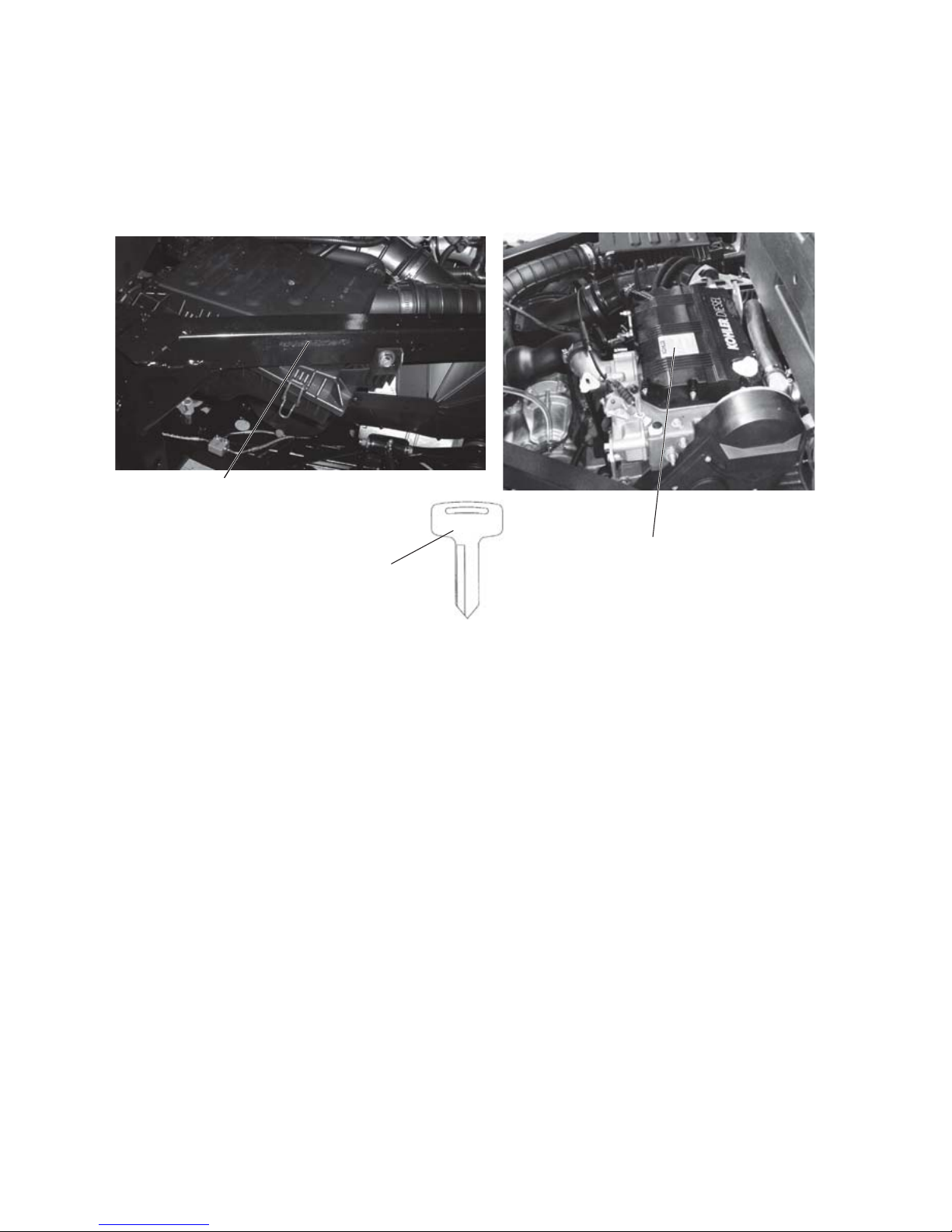
Vehicle Identification Numbers
Record your vehicle's identification numbers and key number in the spaces provided.
Remove the spare key and store it in a safe place. An ignition key can be duplicated only by
ordering a POLARIS key blank (using your key number) and mating it with one of your
existing keys. The ignition switch must be replaced if all keys are lost.
Vehicle Model Number: ________________________________________________________________________
Frame VIN: _________________________________________________________________________________
Engine Serial Number: ________________________________________________________________________
Key Number: ________________________________________________________________________________
Engine Serial Number
VIN
Key Number
####
Page 9

7
INTRODUCTION
European Vibration and Noise
The driver-perceived noise and hand/arm and whole body vibration levels of this machinery
is measured per prEN 15997.
The operating conditions of the machinery during testing:
The vehicles were in like-new condition. The environment was controlled as indicated by the
test procedure(s).
The uncertainty of vibration exposure measurement is dependent on many factors, including:
• Instrument and calibration uncertainty
• Variations in the machine such as wear of components
• Variation of machine operators such as experience or physique
• Ability of the worker to reproduce typical work during measurements
• Environmental factors such as ambient noise or temperature
Page 10
8
SAFETY
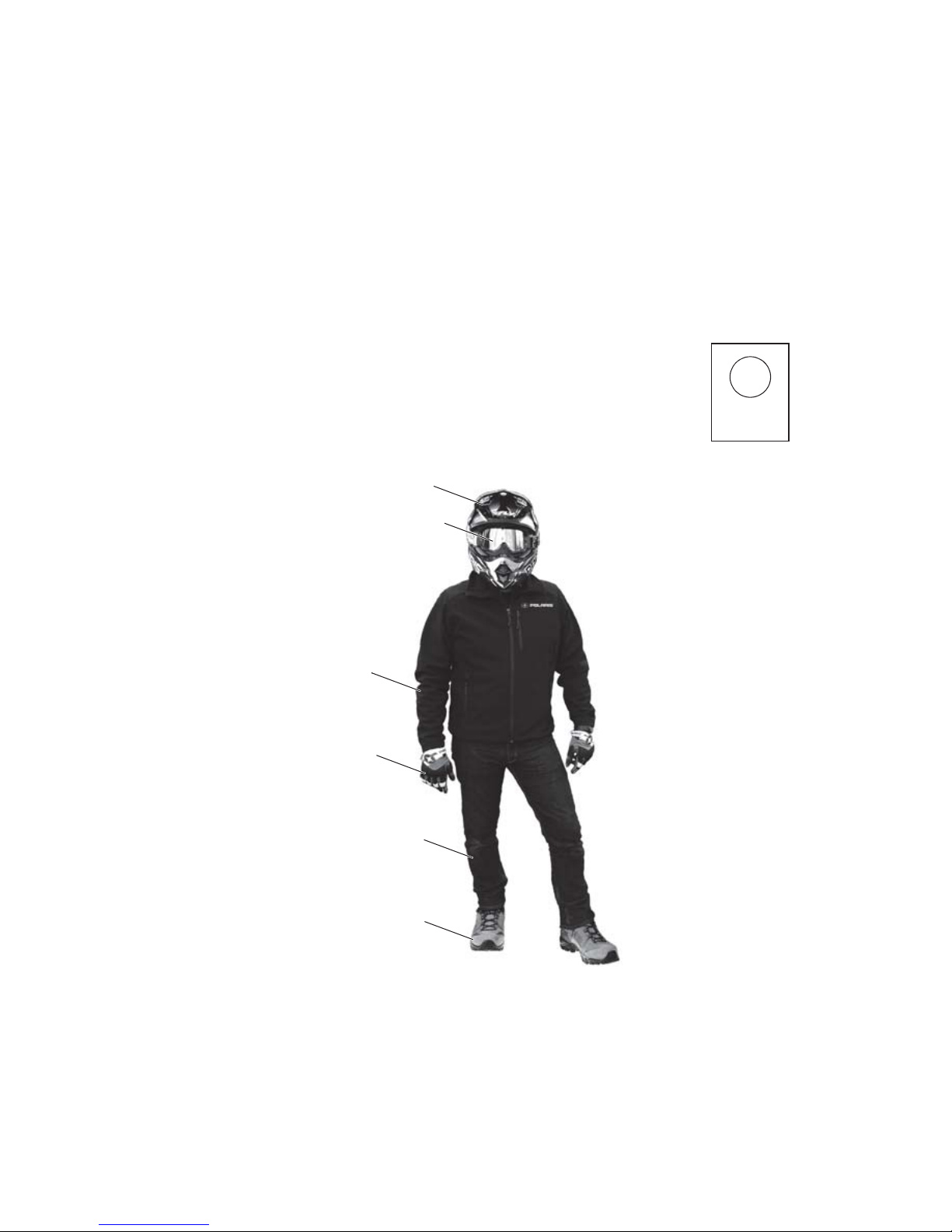
Safe Riding Gear
The driver and all passengers must wear helmet, eye protection, gloves, long-sleeve shirt,
long pants, over-the-ankle boots and seat belt at all times. Protective gear reduces the chance
of injury.
Helmet
Wearing a helmet can prevent a severe head injury. Whenever riding this POLARIS vehicle,
always wear a helmet that meets or exceeds established safety standards.
Approved helmets in the USA and Canada bear a U.S. Department of Transportation (DOT)
label.
Approved helmets in Europe, Asia and Oceania bear the ECE 22.05
label. The ECE mark consists of a circle surrounding the letter E,
followed by the distinguishing number of the country which has granted
approval. The approval number and serial number will also be displayed
on the label.
E
4
051039
0006.31
Helmet
Eye Protection
Gloves
Over-the-Ankle
Boots
Long Pants
Long
Sleeves
Page 11

9
SAFETY
Safe Riding Gear
Eye Protection
Do not depend on eyeglasses or sunglasses for eye protection. Whenever riding this
POLARIS vehicle, always wear shatterproof goggles or use a shatterproof helmet face
shield. POLARIS recommends wearing approved Personal Protective Equipment (PPE)
bearing markings such as VESC 8, V-8, Z87.1, or CE. Make sure protective eye wear is kept
clean.
Gloves
Wear gloves for comfort and for protection from sun, cold weather and other elements.
Boots
Wear sturdy over-the-ankle boots for support and protection. Never ride a POLARIS vehicle
with bare feet or sandals.
Clothing
Wear long sleeves and long pants to protect arms and legs.
Rider Comfort
Under certain operating conditions, heat generated by the engine and exhaust system can
elevate temperatures in the driver and passenger cab area. The condition occurs most
frequently when a vehicle is being operated in high ambient temperatures at low speeds and/
or high load conditions for an extended period of time. The use of certain windshield, roof
and/or cab systems may contribute to this condition by restricting airflow. Any discomfort
due to heat buildup in this area can be minimized by wearing proper riding apparel and by
varying speeds to increase airflow.
Page 12
10
SAFETY
Safety Labels and Locations
Warning labels have been placed on the vehicle for your protection. Read and follow the
instructions of the labels on the vehicle carefully. If any of the labels depicted in this manual
differ from the labels on your vehicle, always read and follow the instructions of the labels
on the vehicle.
If any label becomes illegible or comes off, contact your POLARIS dealer to purchase a
replacement. Replacement safety labels are provided by POLARIS at no charge. The part
number is printed on the label.
Proper Use Warning (Diesel)
Require Proper Use of Your Vehicle
Do your part to prevent injuries:
• Do not allow careless or reckless driving.
• Make sure operators are 16 or older with a valid driver’s license.
• Do not let people drive or ride after using alcohol or drugs.
• Do not allow operation on public roads (unless designated for off-highway vehicle access) - collisions
with cars and trucks can occur.
• Do not exceed seating capacity: 3 occupants.
7179979
Proper Use Warning (CREW Diesel)
Require Proper Use of Your Vehicle
Do your part to prevent injuries:
• Do not allow careless or reckless driving.
• Make sure operators are 16 or older with a valid driver’s license.
• Do not let people drive or ride after using alcohol or drugs.
• Do not allow operation on public roads (unless designated for off-highway vehicle access) - collisions
with cars and trucks can occur.
• Do not exceed seating capacity: 6 occupants.
7179981
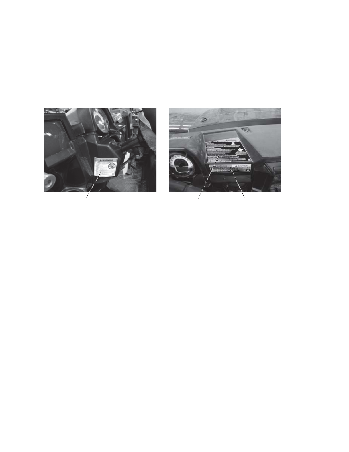
Proper Use
Warning
Payload Warning
Shift Caution
Seat Belt/Drive
Responsibly
Warning
Page 13
11
SAFETY
Safety Labels and Locations
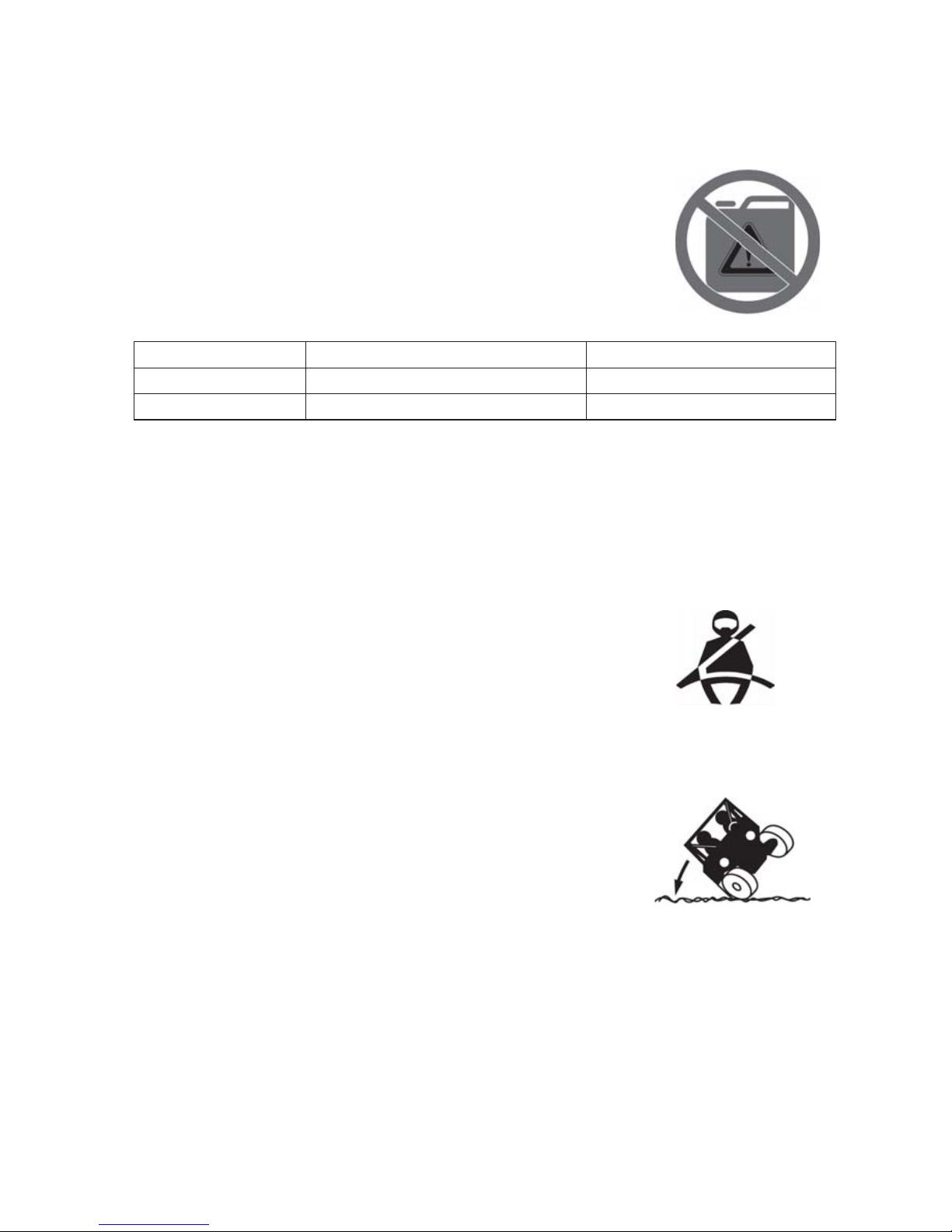
Fuel Transport Warning
This label can be found in the rear cargo box.
WARNING
NEVER carry fuel or other flammable liquids on this vehicle. Failure to
follow this instruction could lead to serious burn injuries or death.
7186122
Payload Warning/Shift Caution
WARNING
CAUTION
To avoid transmission damage, shift only when vehicle is stationary and at idle. When vehicle is
stopped, place shift in parked position.
7181599
Seat Belt/Drive Responsibly Warning
WARNING
Improper vehicle use can result in SEVERE INJURY or DEATH
Be Prepared
• Fasten seat belts.
• Wear an approved helmet and protective gear.
• ALWAYS use cab nets and/or doors.
• Each rider must be able to sit with back against seat, feet flat on the floor,
and hands on steering wheel or hand holds. Stay completely inside the
vehicle.
Drive Responsibly
Avoid loss of control and rollovers:
• Avoid abrupt maneuvers, sideways sliding, skidding or fishtailing,
and never do donuts.
• Slow down before entering a turn.
• Avoid hard acceleration when turning, even from a stop.
• Plan for hills, rough terrain, ruts and other changes in traction and
terrain. Avoid paved surfaces.
• Avoid sidehilling (riding across slopes).
Be Sure Riders Pay Attention and Plan Ah e ad
If you think or feel the vehicle may tip or roll, reduce your risk of injury:
• Keep a firm grip on the steering wheel or hand holds and brace yourself.
• Do not put any part of your body outside of the vehicle for any reason.
LOCATE AND READ OWNER’S MANUAL. FOLLOW ALL INSTRUCTIONS AND WARNINGS.
ALWAYS REVIEW SAFETY VIDEO AND TAKE ROHVA TRAINING (rohva.org).
7185094
RANGER Never Exceed If Total Payload Exceeds
Diesel 20 MPH (32.2 Km/h) 1080 lbs. (490 kg)
CREW Diesel 35 MPH (56.3 Km/h) 1490 lbs. (676 Kg)
Rollovers have caused
severe injuries and death,
even on flat, open areas.
Page 14
12
SAFETY
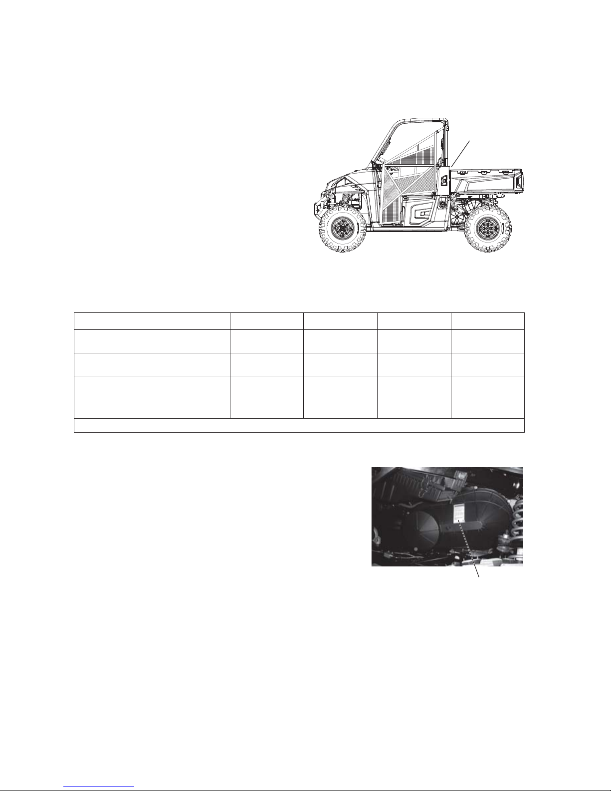
Safety Labels and Locations
Load/Passenger/Tire Pressure Warning
WARNING
• Never carry passengers in cargo box.
• Passengers can be thrown off. This can cause
serious injury or death.
• If total payload is greater than 500 lbs., the
vehicle must be operated in LOW range.
IMPROPER TIRE PRESSURE OR
OVERLOADING CAN CAUSE LOSS OF
CONTROL RESULTING IN SERIOUS INJURY
OR DEATH.
• Reduce speed and allow greater distance for
braking when carrying cargo.
• Overloading or carrying tall, off-center, or
unsecured loads will increase your risk of losing control. Loads should be centered and carried as
low as possible in box.
• For stability on rough or hilly terrain, reduce speed and cargo.
7185781
Clutch Cover Warning
WARNING
Improper service or maintenance of this PVT system can result
in vehicle damage, SEVERE INJURY or DEATH.
Always look for and remove debris inside and around clutch
and vent system when replacing belt.
Read owner’s manual or see authorized POLARIS dealer.
7177469
RANGER Diesel 4x4 4x4 CA CREW CA CREW
MAXIMUM CARGO BOX LOAD 1000 lbs.
(454 kg)
600 lbs.
(272 kg)
1000 lbs.
(454 kg)
600 lbs.
(272 kg)
TIRE PRESSURE IN PSI (KPa) FRONT 10 (69)
REAR 12 (83)
FRONT 10 (69)
REAR 12 (83)
FRONT 14 (96)
REAR 16 (110)
FRONT 14 (96)
REAR 16 (110)
MAXIMUM WEIGHT CAPACITY
INCLUDES WEIGHT OF
OPERATOR, PASSENGER,
CARGO AND ACCESSORIES
1500 lbs.
(682 kg)
1100 lbs.
(499 kg)
1750 lbs.
(795 kg)
1350 lbs.
(612 kg)
Read Operation and Maintenance Manual for more detailed loading information .
X
Clutch Cover
Warning
Page 15

13
SAFETY
Operator Safety
Serious injury or death can result if you do not follow these instructions and procedures, which are
outlined in further detail within your owner's manual.
• Read this entire manual and all labels carefully. Follow the operating procedures
described.
• Never allow anyone under the age of 16 to operate this vehicle and never allow anyone
without a valid driver's license to operate this vehicle.
• Do not carry a passenger until you have at least two hours of driving experience with this
vehicle.
• No person under the age of 12 may ride as a passenger in this vehicle. All riders must be
able to sit with backs against the seat, both feet flat on the floor and both hands on the
steering wheel (if driving) or on a passenger hand hold.
• The driver and all passengers must wear helmet, eye protection, gloves, long-sleeve shirt,
long pants, over-the-ankle boots and seat belt at all times.
• Always use the cab nets (or doors) while riding in this vehicle.
• Always keep hands and feet inside the vehicle at all times.
• Always keep both hands on the steering wheel and both feet on the floorboards of the
vehicle during operation.
• Never permit a guest to operate this vehicle unless the guest has read this manual and all
product labels.
• To reduce rollover risk, be especially careful when encountering obstacles and slopes and
when braking on hills or during turns.
• This vehicle is for off road use only. Never operate on public roads (unless marked for off-
road use). Always avoid paved surfaces.
• Never consume alcohol or drugs before or while operating this vehicle.
• Never operate at excessive speeds. Always travel at a speed proper for the terrain,
visibility and operating conditions, and your experience.
• Never attempt jumps or other stunts.
• Always inspect the vehicle before each use to make sure it's in safe operating condition.
Always follow the inspection procedures described in this manual.
WARNING
Page 16

14
SAFETY
Operator Safety
• Always travel slowly and use extra caution when operating on unfamiliar terrain. Be alert
to changing terrain.
• Never operate on excessively rough, slippery or loose terrain.
• Always follow proper procedures for turning. Practice turning at slow speeds before
attempting to turn at faster speeds. Never turn at excessive speeds.
• Always have this vehicle checked by an authorized POLARIS dealer if it has been
involved in an accident.
• Never operate this vehicle on hills too steep for the vehicle or for your abilities. Practice
on smaller hills before attempting larger hills.
• Always follow proper procedures for climbing hills as described in this manual. See page
47. Check the terrain carefully before attempting to climb a hill. Never climb hills with
excessively slippery or loose surfaces. Never apply throttle suddenly. Never make sudden
gear changes. Never go over the top of a hill at high speed.
• Always follow the proper procedures outlined in this manual for traveling downhill and
for braking on hills. See page 47. Check the terrain carefully before descending a hill.
Never travel downhill at high speed. Avoid going downhill at an angle, which would cause
the vehicle to lean sharply to one side. Travel straight down the hill where possible.
• Always check for obstacles before operating in a new area. Never attempt to operate over
large obstacles such as large rocks or fallen trees. Always follow the proper procedures
outlined in this manual when operating over obstacles. See page 45.
• Always be careful of skidding or sliding. On slippery surfaces such as ice, travel slowly
and exercise caution to reduce the chance of skidding or sliding out of control.
• Never operate your vehicle in fast-flowing water or in water deeper than that specified in
this manual. See page 48. Wet brakes may have reduced stopping ability. Test your brakes
after leaving water. If necessary, apply them lightly several times to let friction dry out the
pads.
• Always be sure there are no obstacles or people behind your vehicle when operating in
reverse. When it's safe to proceed in reverse, move slowly. Avoid turning at sharp angles
in reverse.
Page 17

15
SAFETY
Operator Safety
• Always use the proper size and type of tires specified in this manual. Always maintain
proper tire pressure as specified on safety labels.
• Never modify this vehicle through improper installation or use of non-POLARIS
approved accessories.
• Never exceed the stated load capacity for this vehicle. Cargo should be properly
distributed and securely attached. Reduce speed and follow the instructions in this manual
for hauling cargo or pulling a trailer. Allow a greater distance for braking.
• Always place the transmission in PARK before getting out of the vehicle.
• Always stop the engine before refueling. Remove flammable material containers from the
box before filling them with fuel. Make sure the refueling area is well ventilated and free
of any source of flame or sparks.
• Always remove the ignition key when the vehicle is not in use to prevent unauthorized use
by someone under the age of 16 or without a driver’s license and proper training, or
accidental starting.
FOR MORE INFORMATION ABOUT SAFETY,
call POLARIS at 1-800-342-3764.
Equipment Modifications
Do not install any non-POLARIS approved accessory or modify the vehicle for the purpose
of increasing speed or power. Any modifications or installation of non-POLARIS approved
accessories could create a substantial safety hazard and increase the risk of bodily injury.
The POLARIS limited warranty on your POLARIS vehicle will be terminated if any nonPOLARIS approved equipment and/or modifications have been added to the vehicle that
increase speed or power.
The addition of certain accessories, including (but not limited to) mowers, blades, tires,
sprayers, or large racks, may change the handling characteristics of the vehicle. Use only
POLARIS-approved accessories, and familiarize yourself with their function and effect on
the vehicle.
Page 18

16
SAFETY
Operator Safety
Failure to operate the RANGER properly can result in a collision, loss of control, accident or rollover,
which may result in serious injury or death. Heed all safety warnings outlined in this section of the
owner’s manual. See the OPERATION section of the owner’s manual for proper operating procedures.
Age Restrictions
This vehicle is an ADULT VEHICLE ONLY . NEVER operate this vehicle if
you are under age 16 and NEVER operate without a valid driver’s
license.
Never operate with a passenger under the age of 12. All riders must be
able to sit with backs against the seat, both feet flat on the floor and both
hands on the steering wheel (if driving) or on a passenger hand hold.
Operating Without Instruction
Operating this vehicle without proper instruction increases the risk of an
accident. The operator must understand how to operate the vehicle
properly in different situations and on different types of terrain.
All operators must read and understand the Owner's Manual and all
warning and instruction labels before operating the vehicle.
All operators should review the safety DVD provided with this vehicle and
take a ROHVA training course (www.rohva.org).
Using Alcohol or Drugs
Operating the vehicle after consuming alcohol or drugs could adversely
affect operator judgment, reaction time, balance and perception.
Never drink alcohol or use drugs or medications before or while
operating this vehicle.
Seat Belts
Riding in this vehicle without wearing the seat belt increases the risk of
serious injury in the event of rollover, loss of control, other accident or
sudden stop. Seat belts may reduce the severity of injury in these
circumstances.
All riders must wear seat belts at all times.
Protective Apparel
Riding in this vehicle without wearing an approved helmet and protective eyewear increases the risk of
a serious injuries in the event of an accident.
Operator and all passengers must always wear an approved helmet that fits properly and eye
protection (goggles or face shield).
WARNING
Page 19

17
SAFETY
Operator Safety
Cab Nets
Riding in this vehicle without using the cab nets (or doors, if equipped) increases the risk of serious
injury or death in the event of an accident or rollover. Always use the cab nets (or doors) while riding in
this vehicle.
Always keep hands and feet inside the vehicle at all times.
Failure to Inspect Before Operating
Failure to inspect and verify that the vehicle is in safe operating condition before operating increases
the risk of an accident. Always perform the pre-ride inspection before each use of your RANGER to
make sure it's in safe operating condition. See page 36.
Always follow all inspection and maintenance procedures and schedules described in this owner's
manual. See page 65.
Operating With a Load on the Vehicle
The weight of both cargo and passengers impacts vehicle operation. For your safety and the safety of
others, carefully consider how your vehicle is loaded and how to safely operate the vehicle. Follow the
instructions in this manual for loading, tire pressure, gear selection and speed.
• Do not exceed vehicle weight capacities. The vehicle’s maximum weight capacity is listed in the
specifications section of this manual and on a label on the vehicle. When more passenger weight is
added, cargo weight may need to be reduced accordingly.
• The recommended tire pressures are listed in the specifications section of this manual and on a label
on the vehicle.
Always follow these guidelines:
Under ANY of these conditions: Do ALL of these steps:
Passenger and/or cargo exceeds half the maximum weight capacity 1. Slow down.
2. Verify tire pressure.
3. Use extra caution when
operating.
Operating in rough terrain
Operating over obstacles
Climbing an incline
Towing
Page 20

18
SAFETY
Operator Safety
Exposure to Exhaust
Engine exhaust fumes are poisonous and can cause loss of consciousness or death in a short time.
Never start the engine or let it run in an enclosed area.
The engine exhaust from this product contains chemicals known to cause cancer, birth defects or other
reproductive harm. Operate this vehicle only outdoors or in well-ventilated areas.
Hot Exhaust Systems
Exhaust system components are very hot during and after use of the vehicle. Hot components can
cause burns and fire. Do not touch hot exhaust system components or brake system components.
Always keep combustible materials away from the exhaust system. Use caution when traveling through
tall grass, especially dry grass, to avoid debris build-up around the exhaust system.
Improper Tire Maintenance
Operating this vehicle with improper tires or with improper or uneven tire pressure could cause loss of
control or accident. Always use the size and type of tires specified for your vehicle. Always maintain
proper tire pressure as described in the owner's manual and on safety labels.
Unauthorized Use of the Vehicle
Leaving the keys in the ignition can lead to unauthorized use of the vehicle by someone under the age
of 16, without a drivers license, or without proper training. This could result in an accident or rollover.
Always remove the ignition key when the vehicle is not in use.
Page 21

19
SAFETY
Operator Safety
Turning Improperly
Turning improperly could cause loss of traction, loss of control, accident or rollover. Always follow
proper procedures for turning as described in this owner ’s manual. Neve r turn abruptly or at sharp
angles. Never turn at high speeds. Practice turning at slow speeds before attempting to turn at faster
speeds.
Jumps and Stunts
Attempting wheelies, jumps and other stunts increases the risk of an accident or rollover. Never attempt
wheelies, jumps, or other stunts. Avoid exhibition driving.
Improper Hill Climbing
Climbing hills improperly can cause loss of control or vehicle rollover. Always follow proper procedures
for climbing hills as described in this owner's manual. See page 47.
Descending Hills Improperly
Improperly descending a hill could cause loss of control or rollover. Always follow proper procedures for
traveling down hills as described in this owner’s manual. See page 47.
Stalling While Climbing a Hill
Stalling or rolling backwards while climbing a hill could cause a rollover. Always maintain a steady
speed when climbing a hill.
If all forward speed is lost:
• Apply the brakes.
• Place the transmission in reverse and slowly allow the vehicle to roll straight downhill while applying
light brake pressure to control speed.
If you begin rolling downhill:
• Never apply engine power.
• Apply the brakes gradually until the vehicle is fully stopped.
• Place the transmission in reverse and slowly allow the vehicle to roll straight downhill while applying
light brake pressure to control speed.
Page 22

20
SAFETY
Operator Safety
Operating on Slippery Terrain
Failure to use extra caution when operating on excessively rough, slippery or loose terrain could cause
loss of traction, loss of control, accident or rollover. Do not operate on excessively slippery surfaces.
Always slow down and use additional caution when operating on slippery surfaces.
Skidding or sliding due to loss of traction can cause loss of control or rollover (if tires regain traction
unexpectedly). Always follow proper procedures for operating on slippery surfaces as described in this
owner's manual. See page 46.
Operating on Frozen Bodies of Water
Severe injury or death can result if the vehicle and/or the operator fall through the ice. Never operate
the vehicle on a frozen body of water unless you have first verified that the ice is sufficiently thick to
support the weight and moving force of the vehicle, you and your passengers, and your cargo, together
with any other vehicles in your party.
Always check with local authorities and residents to confirm ice conditions and thickness over your
entire route. Vehicle operators assume all risk associated with ice conditions on frozen bodies of water.
Operating a Damaged Vehicle
Operating a damaged vehicle can result in an accident. After any rollover or other accident, have a
qualified service dealer inspect the entire machine for possible damage, including (but not limited to)
seat belts, rollover protection devices, brakes, throttle and steering systems.
Operating at Excessive Speeds
Operating this vehicle at excessive speeds increases the operator's risk of losing control. Always
operate at a speed that's appropriate for the terrain, the visibility and operating conditions, your skills
and experience and your passengers’ skills and experience.
Operating on Pavement
This vehicle's tires are designed for off-road use only, not for use on pavement. Operating this vehicle
on paved surfaces (including sidewalks, paths, parking lots and driveways) may adversely affect the
handling of the vehicle and may increase the risk of loss of control and accident or rollover. Avoid
operating the vehicle on pavement. If it's unavoidable, travel slowly, travel short distances and avoid
sudden turns or stops.
Operating on Public Roads
Operating this vehicle on public streets, roads or highways could result in a collision with another
vehicle. Never operate this vehicle on any public street, road or highway, including dirt and gravel roads
(unless designated for off-highway use).
Operating in Unfamiliar Terrain
Failure to use extra caution when operating on unfamiliar terrain could result in an accident or rollover.
Unfamiliar terrain may contain hidden rocks, bumps, or holes that could cause loss of control or
rollover. Travel slowly and use extra caution when operating on unfamiliar terrain. Always be alert to
changing terrain conditions.
Page 23
21
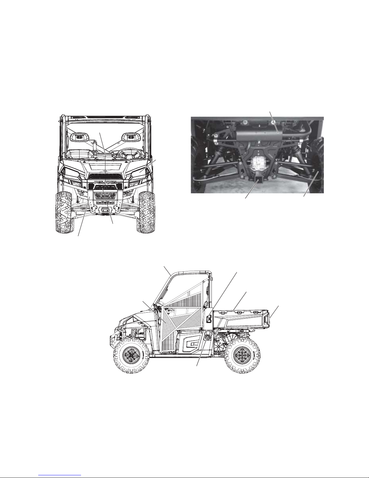
FEATURES AND CONTROLS
Component Locations
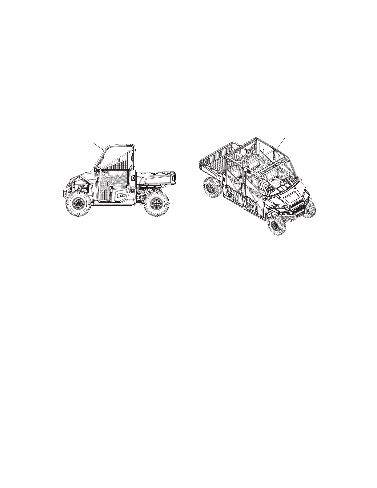
Your vehicle is equipped with cab nets on both sides of the vehicle. Cab nets (or doors, if
equipped) must be used by both operator and passengers at all times. Any illustrations
without cab nets are only to allow component identification. Always use the cab nets (or
doors).
Not all models come with all features. Refer to the specifications section on page 100.
Front Bumper/Brush Guard
Radiator
ROPS Cab
Frame
Console
Cargo Box
Fuel Tank Cap
Cab Net
Receiver
Hitch
CV Boot/Rear
Caliper
Muffler (Spark Arrester)
Tailgate
Intake Screens (both sides)
Headlights
Page 24
22
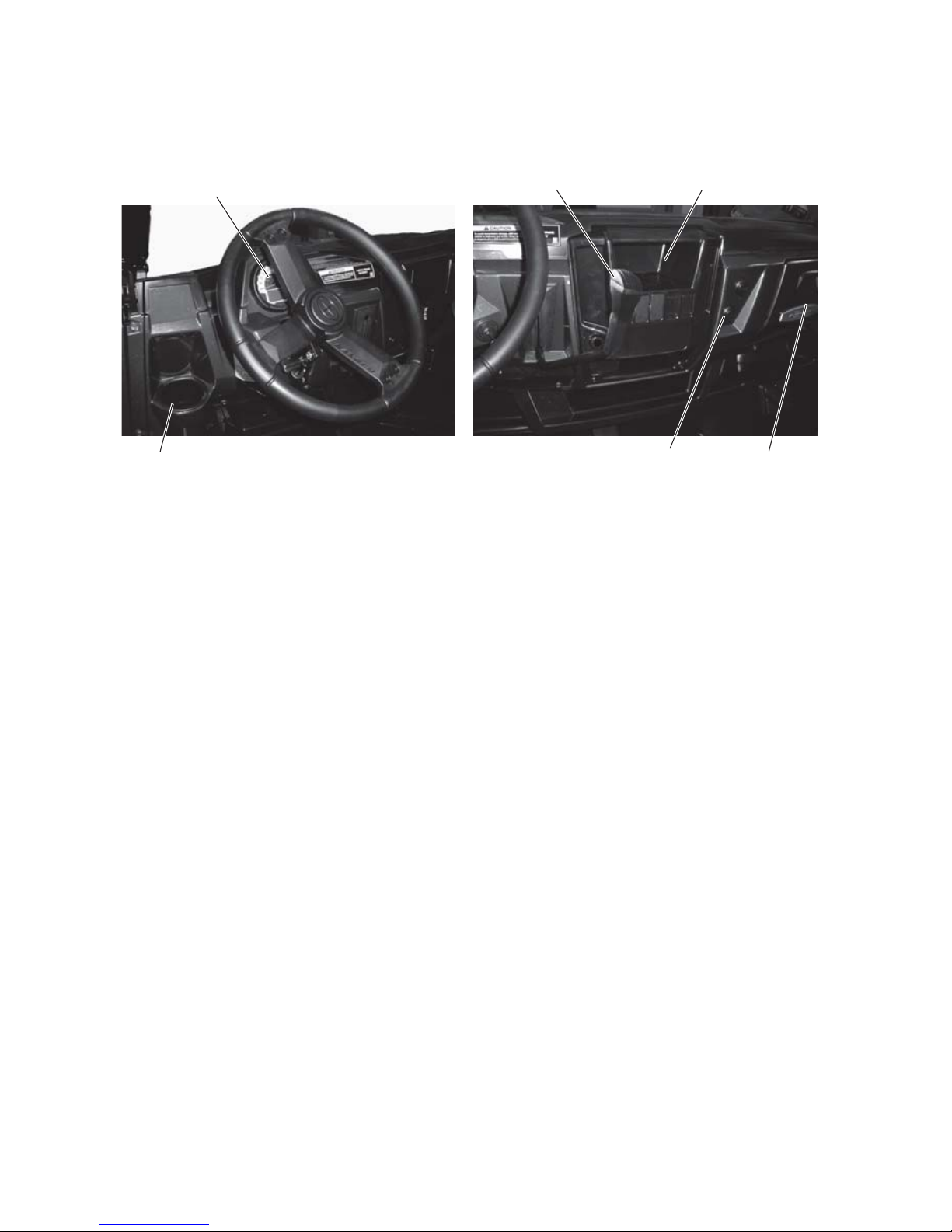
FEATURES AND CONTROLS
Console
Auxiliary Outlets
The 12-volt receptacles have spade connections on the back that may be used to power an
auxiliary light or other optional accessories or lights. The connections are behind the
console, under the dash.
Gear Selector
H: High Gear
L: Low Gear
N: Neutral
R: Reverse
P: Park
Low gear is the primary driving range for the RANGER. High gear is intended for use on
hard-packed surfaces with light loads.
To shift gears, brake to a complete stop. When the engine is idling, move the lever to the
desired gear.
NOTICE: Shifting gears with the engine speed above idle or while the vehicle is moving could cause
transmission damage. Always shift when the vehicle is stationary and the engine is at idle.
Tip: Maintaining shift linkage adjustment is important to assure proper transmission function. Your
POLARIS dealer can assist in resolving any shifting problems.
Using Low Range
Always shift into low gear for any of the following conditions.
• Operating in rough terrain or over obstacles
• Loading the vehicle onto a trailer
• Towing heavy loads
Cup Holder
12V Auxiliary
Outlets
Storage
Tray
Instrument
Cluster
Gear Selector
(Shifter)
Storage
Compartment
Page 25
23
FEATURES AND CONTROLS
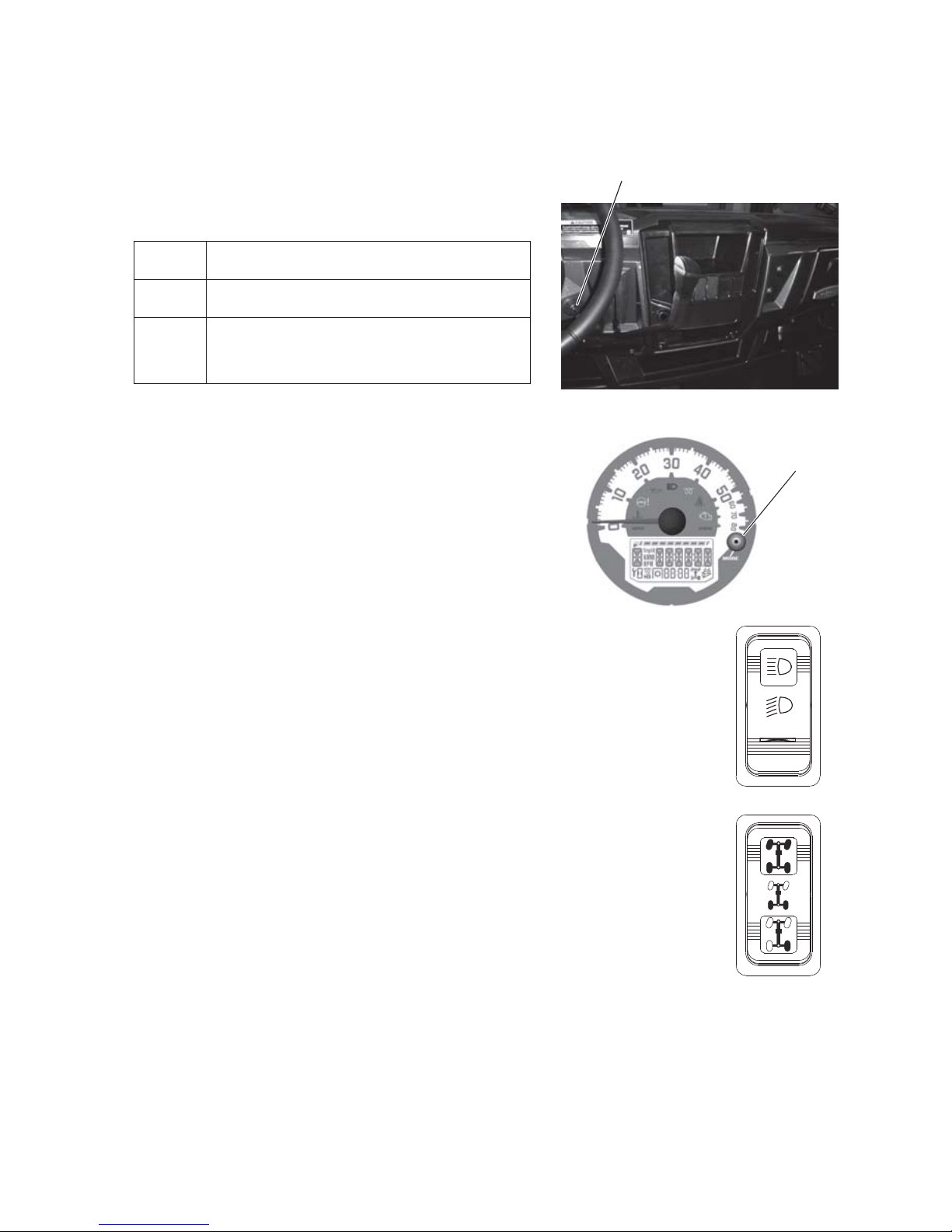
Switches
Ignition Switch
The ignition switch is a three-position, key-operated
switch. The key can be removed from the switch
when it is in the OFF position.
Mode Button
The MODE button is located on the instrument cluster.
Use the MODE button to toggle through mode options
available in the instrument cluster. See pages 30-34.
Light Switch
The ignition switch key must be in the ON/RUN position
to operate the headlights. Press the top of the rocker
switch toward the dash to place the headlights on high
beam. Move the rocker switch to the center position to
place the headlights on low beam. Press the bottom of
the rocker switch to turn off the headlights.
AWD/Differential Lock Switch
The AWD/Differential Switch has three positions:
• All Wheel Drive (AWD)
• Differential Lock (2WD)
• Differential Unlock
Press the top of the rocker switch to engage All Wheel
Drive (AWD). See page 54 for operating instructions.
Move the rocker switch to the center position to lock the
differential and operate in rear wheel drive. Press the
bottom of the switch to unlock the differential and allow
the two rear drive wheels to operate independently. See
page 55 for differential lock operating instructions.
OFF The engine is off. Electrical circuits are off,
except Acc, 12V.
ON Electrical circuits are on. Electrical
equipment can be used.
ST ART After the glow plug indicator light turns off,
turn the key to the START position to engage
the starter. The key returns to the ON
position when released.
Ignition Switch
Mode
Button
HIGH
OFF
LOW
AWD
Differential Lock
Differential Unlock
Page 26
24
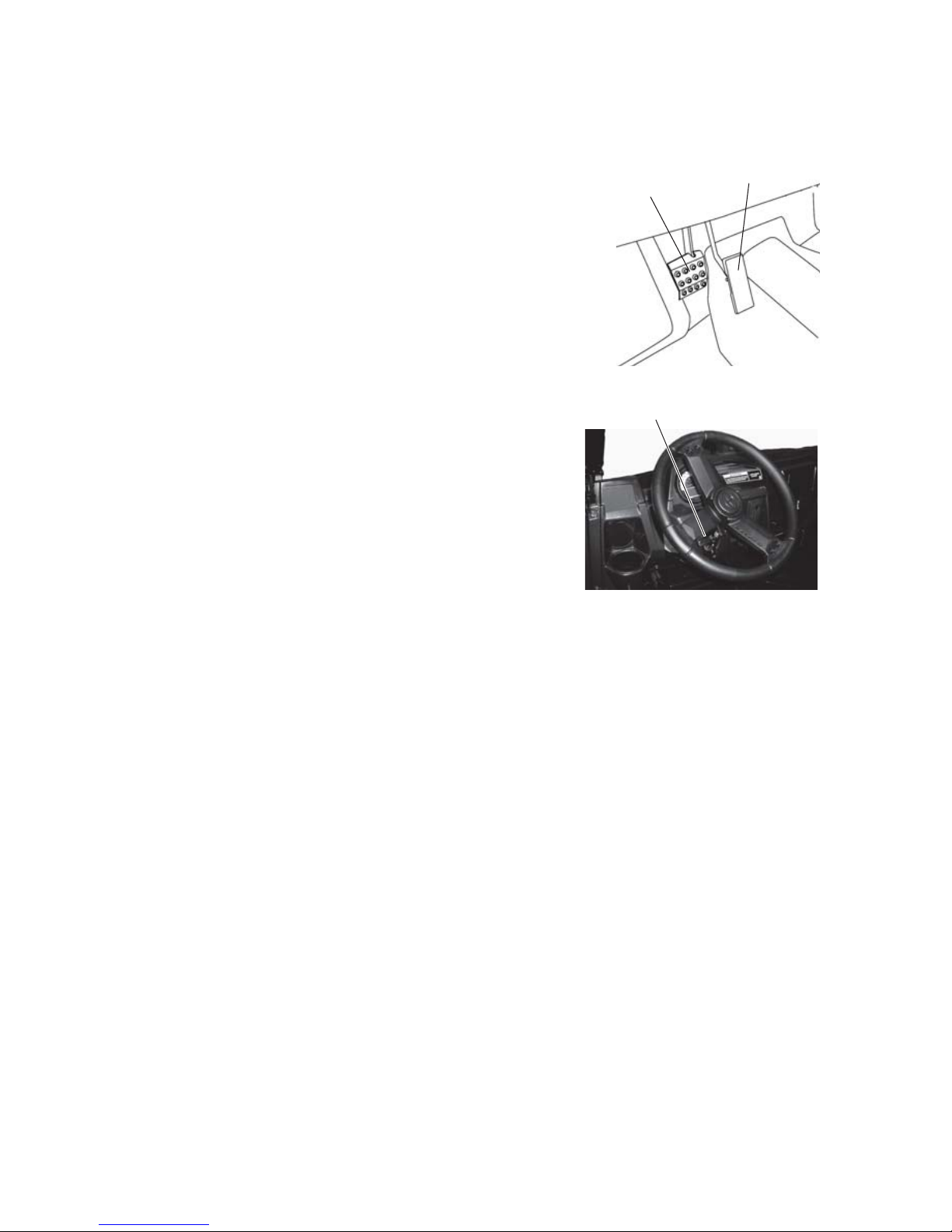
FEATURES AND CONTROLS
Brake Pedal
Depress the brake pedal to slow or stop the vehicle. Apply
the brakes while starting the engine.
Throttle Pedal
Push the throttle pedal down to increase engine speed. Spring
pressure returns the pedal to the rest position when released.
Always check that the throttle pedal returns normally before
starting the engine.
Tip: If the throttle pedal and brake pedal are applied simultaneously,
engine power may be limited.
Adjustable Steering Wheel
The steering wheel can be tilted upward or downward
for rider preference.
Lift and hold the adjustment lever toward you while
moving the steering wheel upward or downward.
Release the lever when the steering wheel is at the
desired position.
Electronic Power Steering (EPS)
Electronic power steering (if equipped) engages when
the ignition key is turned to the ON position. EPS
remains engaged whether the vehicle is moving or idle.
To conserve battery power, the EPS will shut down 5
minutes after the engine is stopped if the key remains in the ON position. The EPS warning
indicator will illuminate to indicate the EPS has shut down. Turn the key off and on to reset
the unit.
Throttle
Pedal
Brake
Pedal
Adjuster
Page 27

25
FEATURES AND CONTROLS
Seat and Storage Compartments
The electrical compartment is located under the center rear-most seat. Never use this area for
storage. Storage compartments are located under all other seats. Remove the storage bin
under the right rear-most passenger seat to access the battery.
Pull the rear edge of a seat upward to release the latch pins from the grommets. Roll the seat
forward to access the under-seat area. To completely remove a seat, roll the seat forward and
lift the seat tabs from the seat base mounts.
Always make sure all seats are properly installed and securely latched before operating. Push
down firmly on the rear of each seat until the latch pins are fully seated into the grommets.
Storage
Compartment
(Under Seat)
Battery
(Under Storage Bin)
Electrical/Fuse
Compartment
(Not For Storage)
Rear-Most Under-Seat Area
Page 28
26
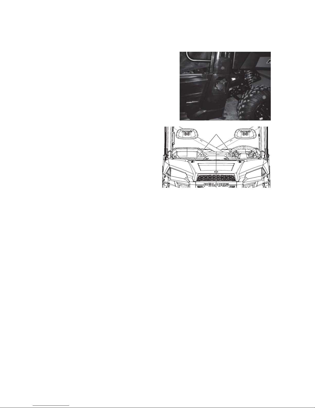
FEATURES AND CONTROLS
Fuel Cap
The fuel tank filler cap is located on the left side
of the vehicle near the driver’s seat. Use only the
recommended diesel fuel. See page 37.
Hood Latches
Remove the hood to access the coolant
overflow bottle, the radiator cap and the
headlight adjustment screws.
To remove the hood, rotate the hood
latches 1/4-turn and lift the hood away
from the vehicle.
Latches
Page 29
27
FEATURES AND CONTROLS
Rollover Protective Structure (ROPS)
The Rollover Protective Structure (ROPS) on this vehicle meets OSHA 1928.53 rollover
performance requirements. Always have your authorized POLARIS dealer thoroughly
inspect the ROPS if it ever becomes damaged in any way.
No device can assure occupant protection in the event of a rollover. Always follow all safe
operating practices outlined in this manual to avoid vehicle rollover.
WARNING! Vehicle rollover could cause severe injury or death. Always avoid operating in a manner
that could result in vehicle rollover.
Trailer Hitch Bracket
This vehicle is equipped with a receiver hitch bracket for a trailer hitch. To avoid injury and
property damage, always heed the warnings and towing capacities outlined on pages 51-52.
ROPS
ROPS
Page 30
28
FEATURES AND CONTROLS
Cab Nets
Riding in this vehicle without using the cab nets (or doors, if equipped) increases the risk of
serious injury or death in the event of an accident or rollover. Cab nets (or doors) must be
used by both operator and passengers at all times. Make sure all latches are secure before
operating the vehicle.
Always inspect cab nets and latches for tightness, wear and damage before each use of the
vehicle. Use the strap adjusters to tighten any loose straps. Promptly replace worn or
damaged cab nets and latches with new cab nets and latches. Please see your authorized
POLARIS dealer.
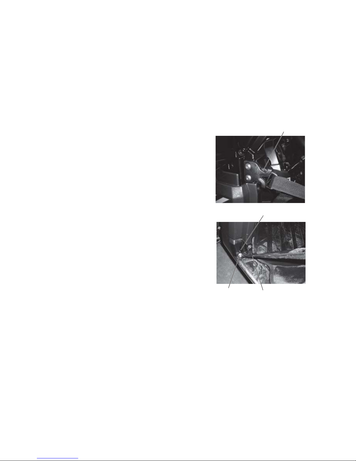
Securing a Net
1. After entering the vehicle, insert the lower net rod
into the net mount on the floor. Make sure the ball
at the end of the rod is properly secured in the
mount.
2. Connect the latch at the top edge of the net to the
receiver latch mounted on the front frame.
Opening a Net
1. To exit the vehicle, release the latch at the top front
edge of the cab net.
2. Rotate the net rearward and pull upward on the
lower net rod to remove it from the mount.
3. Allow the net to hang freely outside the vehicle
while dismounting.
Latch
Rod
Net Mount
Ball
Page 31

29
FEATURES AND CONTROLS
Seat Belts
This POLARIS vehicle is equipped with three-point lap and diagonal seat belts on all seats.
Always make sure the seat belts are secured for all riders before operating.
WARNING! Falling from a moving vehicle could result in serious injury or death. Always fasten your
seat belt securely before operating or riding in the RANGER.
To wear the seat belt properly, follow this
procedure:
1. For 3-point belts, pull the seat belt latch
downward and across your chest toward the
buckle at the inner edge of the seat. The belt
should fit snugly across your hips and
diagonally across your chest. Make sure the
belt is not twisted.
2. Push the latch plate into the buckle until it
clicks.
3. Release the strap, it will self-tighten.
4. To release the seat belt, press the square red
button in the buckle's center.
Seat Belt Inspection
Inspect all seat belts for proper operation before
each use of the vehicle.
1. Push the latch plate into the buckle until it clicks. The latch plate must slide smoothly
into the buckle. A click indicates that it's securely latched.
2. Push the red release latch in the middle of the buckle to make sure it releases freely.
3. Pull each seat belt completely out and inspect the full length for any damage, including
cuts, wear, fraying or stiffness. If any damage is found, or if the seat belt does not
operate properly, have the seat belt system checked and/or replaced by an authorized
POLARIS dealer.
4. To clean dirt or debris from the seat belts, sponge the straps with mild soap and water.
Do not use bleach, dye or household detergents.
Buckle
Latch Plate
Page 32

30
FEATURES AND CONTROLS
Instrument Cluster
Your vehicle is equipped with an instrument cluster that senses vehicle speed from the
transmission. In addition to showing vehicle speed, the speedometer needle flashes when a
warning condition exists.
NOTICE: High water pressure may damage components. Wash the vehicle by hand or with a garden
hose using mild soap.
Certain products, including insect repellents and chemicals, will damage the instrument
cluster lens and other plastic surfaces. Do not use alcohol to clean the instrument cluster.
Do not allow insect sprays to contact the lens. Immediately clean off any fuel that splashes
on the instrument cluster.
Rider Information Center
The rider information display is located in the instrument cluster. All segments will light up
for 1 second at start-up. If the instrument cluster fails to illuminate, a battery over-voltage
may have occurred and the instrument cluster may have shut off to protect the electronic
speedometer. If this occurs, your POLARIS dealer can provide proper diagnosis.
1. Vehicle Speed (Speedometer) Display - Analog display of vehicle speed in MPH or
km/h.
2. Information Display Area - Odometer / Trip Meter / Tachometer / Engine
Temperature / Engine Hours / Service Info - LCD display of the service hour interval,
total vehicle miles or km., total engine hours, a trip meter, engine RPM and engine
temperature.
.
1
19
9
10
11
12
13
14
15
16
17
18
2
3
3
4
5
6
7
8
Page 33

31
FEATURES AND CONTROLS
Instrument Cluster
Rider Information Center
3. MPH / KM/H Display - MPH is displayed when the instrument cluster is in the
Standard mode. KM/H is displayed when the instrument cluster is in the Metric mode.
4. High Beam Indicator - LED icon illuminates whenever the Headlamp switch is in the
high beam position.
5. Fuel Level Indicator - LCD bar graph indicating current fuel level. All segments will
flash when the last segment is cleared indicating a low fuel warning.
6. Clock - Displays current time in either 12-hour or 24-hour formats.
7. Engine Temperature Indicator - LED icon illuminates when the ECM determines the
engine is overheating. The indicators will initially flash to indicate the engine is
overheating. The indicators will stay lit and not flash if a severe overheating condition
exists.
8. Check Engine MIL - Illuminated when the ECM has detected a Diagnostic Trouble
Code in the engine management system.
9. Unit Lock - N/A on this model.
10. Hour Meter - Illuminates when the display (2) is showing hours.
11. Low Oil Pressure Indicator - LED icon illuminates low engine oil or hydraulic fluid
pressure is sensed.
12. Gear Position Indicator - Displays gear selector position.
H = High
L = Low
N = Neutral
R= Reverse Gear
P = Park
-- = Gear Signal Error (shifter stuck between gears)
13. Power Steering System MIL - N/A on this model.
14. Glow Plug Indicator - Illuminated when the glow plugs are active. Light goes out when
the engine is ready to start.
15. Seat Belt Indicator - LED icon illuminates for 10 seconds when the key is turned to the
ON position. The lamp is a reminder to the operator to ensure all riders are wearing seat
belts before operating the vehicle. The driver's seat belt is equipped with a seat belt
interlock. Vehicle speed will be limited to 15 MPH (24 km/h) if the seat belt is not
secured.
16. AWD/TURF Indicator - Illuminate to indicate how many drive wheels are active. This
will tell you if you are in AWD, 2WD, or Turf.
17. ADC Indicator - N/A on this model.
18. Service Interval Indicator - Preset at the factory and adjustable by the user, a flashing
wrench symbol alerts the operator that the preset service interval has been reached and
maintenance should be performed. The wrench icon will flash for 10 seconds upon startup once it reaches 0.
19. Unit of Measurement - Indicates the measurement (Trip 1, Trip 2, KM, MI, RPM)
being displayed in the Information Display Area (2).
Page 34

32
FEATURES AND CONTROLS
Instrument Cluster
Information Display Area
The LCD portion of the instrument cluster is the information display area which displays the
following information: odometer, trip meter, RPM, battery voltage, engine temperature, air
temperature, engine hours, trouble codes, service interval, and clock.
Units of Measurement
To change between Standard and Metric units of measurement, follow these steps:
1. Turn the key to the OFF position.
2. Press and hold the MODE button while turning the key to
the ON position.
3. When the display flashes the distance setting, tap the
MODE button to advance to the desired setting.
4. Press and hold the MODE button to save the setting and
advance to the next display option.
5. Repeat the procedure to change remaining display settings.
Odometer
The odometer records and displays the total distance traveled
by the vehicle. The odometer can not be reset.
Trip Meter
The trip meter records the miles traveled by the vehicle on
each trip. To reset the trip meter:
1. Toggle the MODE button to TRIP 1.
2. To reset to 0, push and hold the MODE button until the
distance display changes to 0.
Engine Hours
1. Engine hours are logged anytime the engine is running.
Total hours can not be reset.
Distance Miles (MPH) Kilometers (KM/H)
Temperature Fahrenheit Celsius
Time 12-Hour Clock 24-Hour Clock
Page 35

33
FEATURES AND CONTROLS
Instrument Cluster
Information Display Area
Tachometer (RPM)
Engine RPM can be displayed digitally.
Engine Temperature
Engine temperature can be displayed in °F or °C. Refer to
“Units of Measurement” to change the format.
Clock
The clock displays the time in a 12-hour or 24-hour format.
Refer to “Units of Measurement” to change the format
(Standard 12-hour / Metric 24-hour). To set the clock, follow
these steps:
1. Toggle the MODE button until the odometer is displayed.
2. Press and hold the MODE button until the hour segment
flashes. Release the button.
3. With the segment flashing, tap the MODE button to advance to the desired setting.
4. Press and hold the MODE button until the next segment flashes. Release the button.
5. Repeat steps 3-4 twice to set the 10 minute and 1 minute segments. After completing the
1-minute segment, step 4 will save the new settings and exit the clock mode.
Battery Under / Over Voltage
This warning usually indicates that the vehicle is operating at an RPM too low to keep the
battery charged. It may also occur when the engine is at idle and a high electrical load is
applied (lights, cooling fan or other accessories).
Battery Voltage Low
If battery voltage drops below 11 volts, a warning screen will
display “Lo” and provide the present battery voltage. If
voltage drops below 8.5 volts, LCD back-lighting and icons
will turn off.
Page 36

34
FEATURES AND CONTROLS
Instrument Cluster
Information Display Area
Programmable Service Interval
The initial factory service interval setting is 50 hours. Each
time the engine is started, the engine hours are subtracted
from the service interval hours. When the service interval
reaches 0, the LCD wrench icon will flash for approximately
10 seconds each time the engine is started.
To change the hour setting or reset the function, follow these
steps:
1. Toggle the MODE button until the wrench icon is displayed in the information area.
2. Press and hold the MODE button until the information display area begins to flash.
3. Toggle the MODE button to increase the service interval hours in 5 hour increments to a
maximum of 100 hours.
4. To turn off the service interval function, toggle the MODE
button until “OFF” is displayed.
Check Engine / Trouble Code Display
The diagnostic mode is accessible only when the check
engine MIL has been activated.
Use the following procedure to display diagnostic trouble
codes that were activated during current ignition cycle
causing the MIL to illuminate. Diagnostic trouble codes will
remain stored in the gauge (even if MIL turns off) until the
key is turned off.
1. If the trouble codes are not displayed, use the MODE button to toggle until “CK ENG”
displays on the information display area.
2. Press and hold the MODE button to enter the diagnostics code menu.
3. A set of three numbers will appear in the information area.
4. The first number (located far left) can range from 0 to 9. This number represents the total
number of trouble codes present (example: 3 means there are 3 codes present).
5. The second number (located top right) can be 2 to 6 digits in length. This number
equates to the suspected area of fault (SPN).
6. The third number (located bottom right) can be 1 to 2
digits in length. This number equates to the fault mode
(FMI).
7. See your dealer for Diagnostic Trouble Codes.
8. If more than one code exists, press the MODE button to
advance to the next trouble code.
9. To exit the diagnostic mode, press and hold the MODE
button or turn the ignition key OFF once the codes are
recorded.
Page 37

35
OPERATION
Failure to operate the vehicle properly can result in a collision, loss of control, accident or rollover,
which may result in serious injury or death. Read and understand all warnings outlined in the safety
section of this manual.
Break-In Period
The break-in period for your new RANGER is the first 50 hours of operation. No single
action on your part is as important as a proper break-in period. Careful treatment of a new
engine will result in more efficient performance and longer life for the engine. Perform the
following procedures carefully.
NOTICE: Excessive heat build-up during the first three hours of operation will damage close-fitted
engine parts. Do not operate at full throttle or high speeds for extended periods during the
first three hours of use.
Engine and Drivetrain Break-in
1. Fill the fuel tank with clean, fresh fuel.
2. Check the oil level. Add the recommended oil as needed to maintain the oil level in the
normal (safe) operating range.
3. Drive slowly at first. Select an open area that allows room to familiarize yourself with
vehicle operation and handling.
4. Vary throttle positions. Do not operate at sustained idle.
5. Perform regular checks on fluid levels, controls and areas outlined on the daily pre-ride
inspection checklist. See page 36.
6. During the break-in period, change both the oil and the filter at 50 hours.
7. Check fluid levels of transmission and all gearcases after the first 25 hours of operation
and every 100 hours thereafter.
8. Pull only light loads.
PVT Break-in (Clutches/Belt)
A proper break-in of the clutches and drive belt will ensure a longer life and better
performance. Break in the clutches and belt by operating at slower speeds during the breakin period as recommended. Pull only light loads. Avoid aggressive acceleration and high
speed operation during the break-in period.
If a belt fails, always clean any debris from the clutch air duct and from the engine
compartment. See page 77.
WARNING
Page 38

36
OPERATION
Pre-Ride Inspection
Failure to inspect and verify that the vehicle is in safe operating condition before operating
increases the risk of an accident. Always inspect the vehicle before each use to make sure it's
in safe operating condition.
Item Remarks Page
Brake system/pedal travel Ensure proper operation 24
86
Brake fluid Ensure proper level 86
Front suspension Inspect, lubri cate if necessary 68
Rear suspension Inspect, lub ricate if necessary 68
Steering Ensure free operation 87
Tires Inspect condition and pressure 89
Wheels/fasteners Inspect, ensure fastener tightness 89
Frame nuts, bolts, fasteners Inspect, ensure tightness Fuel and oil Ensure proper levels 31
69
Coolant level Ensure proper level 75
Coolant hoses Inspect for leaks Throttle Pedal Ensure proper operation Indicator lights/switches Ensure operation 23
Intake Screens (2) Inspect, clean 81
Air filter Inspect 81
Headlamp Verify proper operation
Brake light/tail lamp Verify proper operation
Seat Belts Check length of belt for damage, check latches for
proper operation
29
Cab Nets Check for wear or damage, ensure proper installation 28
PVT Inspect and drain if any water 79
Page 39

37
OPERATION
Fuel Recommendations
NOTICE: For the best engine performance, to prevent engine damage and to comply with EPA/CARB
warranty requirements, use ONLY the recommended diesel fuels. Use only CLEAN diesel
fuel.
POLARIS recommends the following diesel fuels for use in this vehicle:
• Ultra Low Sulfur #2
• #1 Diesel Fuel containing no more than 20% bio-diesel (see page 38)
See page 40 for cold weather fuel blend recommendations. For more information about
recommended diesel fuels and the consequences of using bio-diesel fuel exceeding 20% bio-
diesel, see Additional Technical Fuel Requirements below.
Diesel fuel should comply with the following world-wide specifications.
Additional Technical Fuel Requirements
• The fuel cetane number should be equal to 45 or higher.
• The sulfur content must not exceed 0.5% by volume. Less than 0.5% is preferred.
Especially in the U.S.A. and Canada, Ultra Low Sulfur fuel should be used.
• Bio-Diesel fuels: see pages 38-39.
• NEVER mix kerosene, used engine oil or residual fuels with diesel fuel.
• Water and sediment in the fuel should not exceed 0.05% by volume.
• Keep the fuel tank and fuel-handling equipment clean at all times.
• Poor quality fuel can reduce engine performance and/or cause engine damage.
• Fuel additives are not recommended. Some fuel additives may cause poor engine
performance.
• Ash content must not exceed 0.01% by volume.
• Carbon residue content must not exceed 0.35% by volume. Less than 0.1% is preferred.
• Total aromatics content should not exceed 35% by volume. Less than 30% is preferred.
• PAH (polycyclic aromatic hydrocarbons) content should be below 10% by volume.
• Metal content of Na, Mg, Si and Al should be equal to or lower than 1 mass ppm (test
analysis method JPI-5S-44-95).
• Lubricity: Wear mark of WS1.4 should be Max. 0.018 in. (460μm) at HFRR test.
Diesel Fuel Specification Location
ASTM D975
No. 1D S15, S500
No. 2D S15, S500
USA
EN590:96 European Union
ISO 8217 DMX International
BS 2869-A1 or A2 United Kingdom
JIS K2204 Grade No. 2 Japan
KSM-2610 Korea
GB252 China
Page 40

38
OPERATION
Fuel Recommendations
Bio-Diesel Fuels
In Europe and in the United States, as well as some other countries, non-mineral oil based
fuel resources such as RME (Rapeseed Methyl Ester) and SOME (Soybean Methyl Ester),
collectively known as FAME (Fatty Acid Methyl Esters), are being used as extenders for
mineral oil derived diesel fuels.
KOHLER approves the use of bio-diesel fuels that do not exceed a blend of 20% (by
volume) of FAME with 80% (by volume) of approved mineral oil derived diesel fuel. Such
bio-diesel fuels are known in the marketplace as B20 diesel fuels.
These B20 diesel fuels must meet certain requirements:
1. The bio-fuels must meet the minimum specifications for the country in which they are
used.
• In Europe, bio-diesel fuels must comply with the European Standard EN14214.
• In the United States, bio-diesel fuels must comply with the American Standard ASTMD-6751.2.
2. Bio-fuels should be purchased only from recognized and authorized diesel fuel suppliers.
Precautions and concerns regarding the use of bio-fuels:
1. Free methanol in FAME may result in corrosion of aluminum and zinc FIE components.
2. Free water in FAME may result in plugging of fuel filters and increased bacterial growth.
3. High viscosity at low temperatures may result in fuel delivery problems, injection pump
seizures and poor injection nozzle spray atomization.
4. FAME may have adverse effects on some elastomers (seal materials) and may result in
fuel leakage and dilution of the engine lubricating oil.
5. Even bio-diesel fuels that comply with a suitable standard as delivered will require
additional care and attention to maintain the quality of the fuel in the equipment or other
fuel tanks. It is important to maintain a supply of clean, fresh fuel. Regular flushing of
the fuel system and/or fuel storage containers may be necessary.
6. The use of bio-diesel fuels that do not comply with the standards as agreed to by the
diesel engine manufacturers and the diesel fuel injection equipment manufacturers, or
bio-diesel fuels that have degraded as per the precautions and concerns above, may
affect the warranty coverage of your engine.
Page 41

39
OPERATION
Fuel Recommendations
Bio-Diesel Fuels
B21 To B100 Bio-diesel Fuel Blend Usage
B21 to B100 bio-diesel is not approved for this POLARIS application.
Approved Engines
Only the KOHLER KDW engine series listed below may operate with bio-diesel fuel
concentrations up to B20 for POLARIS applications.
NOTICE: Do not exceed bio-diesel fuel blend B20 for this POLARIS application.
• KDW 1003
Approved Fuel
NOTICE: Raw pressed vegetable oils are not considered bio-diesel, and are unacceptable for use as
fuel in any concentration in KOHLER engines.
Bio-diesel fuel blends up to B20 must comply with the following standards:
• EN14214 (European standard) and/or ASTM D-6751 (American standard).
• All applicable engines may operate with bio-diesel fuel up to a maximum B20 (20% biodiesel blend) concentration.
Operating Conditions with B20 Bio-diesel Fuel Blends
Engine Warranty
Damages, performance or service concerns determined to be caused by the use of bio-diesel
fuel not meeting the specifications outlined above are not considered to be defects in
material or factory workmanship and are not covered under warranty. The same applies to
damages or other concerns induced by not complying with the recommended operating
conditions of KOHLER engines with bio-diesel fuel.
Handling Fuel
WARNING! Diese l fuel is flammable and explosive under certain conditions.
• NEVER refuel with the engine running.
• Always refuel outdoors or in a well ventilated area.
• Fill the fuel tank with diesel fuel ONLY. Filling the fuel tank with gasoline may result in a fire and will
damage the engine.
• Remove flammable material containers from the box before filling them with fuel.
• Do not smoke or allow open flames or sparks in or near the area where refueling is performed or
where fuel is stored.
• Wipe up all spills immediately.
• Keep sparks, open flames or any other form of ignition (match, cigarette, static electricity source)
well away when refueling.
• NEVER remove the fuel cap while the engine is running.
• NEVER overfill the fuel tank. Do not fill the tank neck.
• If fuel spills on your skin or clothing, immediately wash it off with soap and water and change
clothing.
Page 42

40
OPERATION
Fuel Recommendations
Refueling
The fuel tank filler cap is located on the right side of the vehicle
near the passenger seat. Remove the cap and add the recommended
fuel to the bottom of the filler neck. Do not overfill.
Cold Weather Operation
Cold weather operation can result in fuel gelling if the incorrect fuel type is used. Use the
following fuel blending guideline to prevent this from occurring.
Block Heater Use
If this vehicle will be operated when temperatures are in the +5° to -25° F. (-15° to -32° C)
range, a block heater must be installed. Please see your dealer to purchase a block heater kit.
NOTE: Block heater is not recommended when the vehicle is operated above 25° F temperature.
Fuel Blending Guideline
Temperature No. 2 No. 1
+15° F (-9° C) 100% 0%
Down to -20° F (-29° C) 50% 50%
Below -20° F (-29° C) 0% 100%
Cold Starting Guidelines
Temperature
+20° F to +15° F
(-7° C to -9° C)
+15° F to +5° F
(-9° C to -15° C)
+5° F to -20° F
(-15° C to -29° C)
-20° F to -25° F
(-29° C to -32° C)
Fuel #2 Diesel 50/50 mix #1/#2 diesel #1 Diesel
5W-40 Synthetic
Diesel Engine Oil
Optional Recommended Required
Block heater Optional Recommended Required
Throttle (apply throttle
75%-100% during
cranking)
Optional Required
Battery condition/
connections
Charged battery (12.8 VDC)
Proper glow plug
usage (wait for the
light)
Wait for light at all temps
Oil pan heater Not needed Optional (helps to reduce cranking)
Page 43

41
OPERATION
Cold Weather Operation
Bio-Diesel Blended Fuel
NOTICE: Never use bio-diesel blended fuel containing more than 20% bio-diesel in this vehicle. See
page 38.
Bio-diesel blended fuel has unique qualities that should be considered before using it in
this vehicle:
• Cold weather conditions can lead to plugged fuel system components and hard starting.
• Bio-diesel blended fuel is an excellent medium for microbial growth and contamination
which can cause corrosion and plugging of fuel system components.
• Use of bio-diesel blended fuel may result in premature failure of fuel system components,
such as plugged fuel filters and deteriorated fuel lines.
• Shorter maintenance intervals may be required, such as cleaning the fuel system and
replacing fuel filters and fuel lines.
• Using bio-diesel blended fuels containing more than 20% bio-diesel can affect engine life
and cause deterioration of hoses, tubes, injectors, injector pump and seals.
Use the following guidelines if bio-diesel blended fuel is used:
• Never use bio-diesel blended fuel containing more than 20% bio-diesel in this vehicle.
• Ensure the fuel tank is as full as possible at all times to prevent moisture from collecting in
the fuel tank.
• Ensure that the fuel tank cap is securely tightened.
• Clean up any spilled fuel immediately to prevent damage to painted surfaces.
• Drain all water from the fuel filter daily before operating the vehicle.
• Do not exceed the engine oil change interval. Extended intervals can result in engine
damage.
• Before vehicle storage, drain the fuel tank, refill with 100% petroleum diesel fuel, add fuel
stabilizer and run the engine for at least 30 minutes.
NOTICE: Bio-diesel blended fuel does not have long term stability and should not be stored for more
than three months.
Page 44

42
OPERATION
Operating Conditions
NOTICE: Observe the following environmental operating conditions to maintain engine performance
and avoid premature engine wear.
• Avoid operating in the presence of chemical gases or fumes.
• Avoid operating in a corrosive atmosphere such as salt water spray.
• NEVER operate the engine in a floodplain unless proper precautions are taken to avoid
being subject to a flood.
• NEVER expose the engine to the rain.
• The standard range of ambient temperatures for the normal operation of KOHLER engines
is from +5° F (-15° C) to +104° F (+40° C).
• If the ambient temperature exceeds +104° F (+40° C), the engine may overheat and cause
the engine oil to break down.
• If the ambient temperature is between +5° F (-15° C) and -25° F (-32° C), POLARIS
recommends the use of a block heater. See page 40.
Page 45

43
OPERATION
Starting the Engine
NOTICE: NEVER use an engine starting aid such as ether. Engine
damage will result.
Before operating this vehicle in cold weather, review the cold
weather operation information beginning on page 40.
Always wait for the glow plug indicator light to turn off
before cranking the engine.
1. Always start the engine outdoors or in a well-ventilated
area.
2. Sit in the driver's seat and fasten the seat belt. Secure the
cab nets (or doors).
3. Place the transmission in PARK.
4. Apply the brakes. Do not press the throttle pedal while starting the engine.
5. Turn the ignition switch to the ON position and wait for the glow plug indicator light to
turn off.
6. Turn the ignition key past the ON/RUN position to START. Engage the starter for a
maximum of five seconds. Release the key when the engine starts.
7. If the engine does not start within five seconds, release the ignition switch and wait five
seconds. Repeat steps 6 and 7 until the engine starts.
NOTICE: Operating the vehicle immediately after starting could cause engine damage. Allow the
engine to warm up for several minutes before operating the vehicle.
Stopping the Engine
For maximum engine life, allow the engine to idle, without load, for 5 minutes. This will
allow the engine components that operate at high temperatures, such as the exhaust system,
to cool slightly before the engine is shut down.
1. Release the throttle pedal completely and brake to a complete stop.
2. Place the transmission in PARK.
3. Turn the engine off and remove the key to prevent unauthorized use.
4. Slowly release the brake pedal and make sure the transmission is in PARK before exiting
the vehicle.
WARNING! A rolling vehicle can cause serious injury. Always place the transmission in PARK when
stopping the engine.
Braking
1. Release the throttle pedal completely.
Tip: When the throttle pedal is released completely and the engine speed drops near an idle, the
vehicle has no engine braking.
2. Press on the brake pedal evenly and firmly.
Tip: If the throttle pedal and brake pedal are applied simultaneously, engine power may be limited.
3. Practice starting and stopping (using the brakes) until you're familiar with the controls.
START
HELP
Page 46

44
OPERATION
Driving Procedure
1. Wear a helmet, eye protection, gloves, long-sleeve shirt, long pants and over-the-ankle
boots.
2. Perform the pre-ride inspection. See page 36.
3. Sit in the driver's seat and fasten the seat belt.
4. Always use the cab nets (or doors) while riding in this vehicle.
5. Place the transmission in PARK.
6. Start the engine and allow it to warm up.
7. Apply the service brakes and shift the transmission into gear.
8. Check your surroundings and determine your path of travel.
9. Keeping both hands on the steering wheel, slowly release the brakes and slowly depress
the throttle with your right foot to begin driving.
10. Drive slowly. Practice maneuvering and using the throttle and brakes on level surfaces.
11. Do not carry a passenger until you have at least two hours of driving experience with this
vehicle.
Page 47

45
OPERATION
Driving with a Passenger
1. Perform the pre-ride inspection. See page 36.
2. Make sure all passengers are at least 12 years of age and tall enough to comfortably and
safely sit in a passenger seat with the seat belt secured, put both feet on the floor and
grasp the hand hold.
3. Make sure all passengers are wearing an approved helmet, eye protection, gloves, long-
sleeve shirt, long pants and over-the-ankle boots.
4. Make sure all passengers secure their seat belt.
5. Make sure all cab nets (or doors) are properly secured.
6. Do not carry more than the recommended number of passengers for your vehicle. See
page 10.
7. Allow a passenger to ride only in a passenger seat.
8. Slow down. Always travel at a speed appropriate for your skills, your passengers’ skills,
and operating conditions. Avoid unexpected or aggressive maneuvers that could cause
discomfort or injury to a passenger.
9. Vehicle handling may change with a passenger and/or cargo on board. Allow more time
and distance for braking.
10. Always follow all operating guidelines as outlined on safety labels and in this manual.
Driving Over Obstacles
Follow these precautions when operating over obstacles:
1. Always check for obstacles before operating in a new area.
2. Look ahead and learn to read the terrain. Be constantly alert for hazards such as logs,
rocks and low hanging branches.
3. Travel slowly and use extra caution when operating on unfamiliar terrain. Not all
obstacles are immediately visible.
4. Avoid operating over large obstacles such as large rocks and fallen trees. If unavoidable,
use extreme caution and operate slowly.
5. Always have all passengers dismount and move away from the vehicle before operating
over an obstacle that could cause a rollover.
Page 48

46
OPERATION
Driving on Slippery Surfaces
Skidding or sliding can cause loss of control or rollover (if tires regain traction unexpectedly). When
operating on slippery surfaces such as ice or loose gravel, reduce speed and use extra caution to
reduce the chance of skidding or sliding out of control. Do not operate on excessively slippery surfaces.
Whenever riding on slippery surfaces such as wet trails or loose gravel, or during freezing
weather, follow these precautions:
1. Do not operate on excessively rough, slippery or loose terrain.
2. Slow down before entering slippery areas.
3. Maintain a high level of alertness, reading the trail and avoiding quick, sharp turns,
which can cause skids.
4. Engage all-wheel drive before wheels begin to lose traction.
NOTICE: Severe damage to the drive train may occur if the AWD is engaged while the wheels are
spinning. Always allow the wheels to stop spinning before engaging AWD.
5. Correct a skid by turning the steering wheel in the direction of the skid. Never apply the
brakes during a skid.
WARNING
Sideways
skid
Turn in
direction of
skid
Page 49

47
OPERATION
Driving Uphill
Whenever traveling uphill, follow these precautions:
1. Always travel straight uphill.
2. Avoid excessively steep hills.
3. Keep both feet on the floor.
4. Always check the terrain carefully before
ascending any hill. Never climb hills with
excessively slippery or loose surfaces.
5. Proceed at a steady rate of speed and throttle
pedal position. Never apply throttle suddenly.
6. Never go over the crest of a hill at high speed.
An obstacle, a sharp drop, or another vehicle
or person could be on the other side of the hill.
Driving on a Sidehill (Sidehilling)
Driving on a sidehill is not recommended. Improper procedure could cause loss of control or
rollover. Avoid crossing the side of any hill unless absolutely necessary.
If crossing a sidehill is unavoidable, follow these precautions:
1. Slow down.
2. Exercise extreme caution.
3. Avoid crossing the side of a steep hill.
Driving Downhill
When driving downhill, follow these
precautions:
1. Avoid excessively steep hills.
2. Drive straight downhill. Avoid descending
a hill at an angle, which would cause the
vehicle to lean sharply to one side. Travel
straight downhill when possible.
3. Slow down.
4. Apply the brakes slightly to aid in slowing.
5. When transporting heavy loads and/or
when towing, always operate the vehicle in
low gear and have ADC activated (if
equipped).
Page 50

48
OPERATION
Driving Through Water
Your POLARIS RANGER can operate through water up to a maximum recommended depth
equal to the floorboards.
NOTICE: If your vehicle becomes immersed or is operated in water that exceeds the floor level,
service is required before starting the engine. Your POLARIS dealer can provide this
service. If it's impossible to bring the vehicle in before starting the engine, perform the
service outlined on page 80, and take the vehicle in for service at the first opportunity.
Follow these procedures when operating
through water:
1. Determine water depths and current
before entering water.
2. Choose a crossing where both banks
have gradual inclines.
3. Proceed slowly, avoiding rocks and
obstacles.
4. Avoid operating through deep or fast-
flowing water.
WARNING! The large tires on your RANGER
may cause the vehicle to float in deep or fastflowing water, which could result in loss of
control and lead to serious injury or death.
Never cross deep or fast-flowing water with
your RANGER.
5. After leaving water, always dry the brakes by applying light pressure to the pedal
repeatedly until braking action is normal. Avoid applying brake and throttle at the same
time.
NOTICE: After running your vehicle in water, it's critical that you perform the services outlined in the
Periodic Maintenance Chart beginning on page 65. Give special attention to engine oil,
transmission oil, all gearcase fluids, and all grease fittings.
Floorboard
Page 51

49
OPERATION
Driving in Reverse
Follow these precautions when operating in reverse:
1. Always check for obstacles or people behind the vehicle. Always inspect left and right
fields of vision before backing.
2. Always avoid backing downhill.
3. Back slowly.
4. Apply the brakes lightly for stopping.
5. Avoid turning at sharp angles.
6. Apply only light throttle. Never apply throttle suddenly.
Page 52

50
OPERATION
Parking the Vehicle
1. Apply the brakes. Stop the vehicle on a level surface.
2. When parking inside a garage or other structure, be sure that the structure is well
ventilated and that the vehicle is not close to any source of flame or sparks, including
any appliance with pilot lights.
3. Place the transmission in PARK.
4. Turn the engine off.
5. Slowly release the brake pedal and make sure the transmission is in PARK before exiting
the vehicle.
6. Remove the ignition switch key to prevent unauthorized use.
Parking on an Incline
Avoid parking on an incline if possible. If it's
unavoidable, follow these precautions:
1. Apply the brakes.
2. Place the transmission in PARK.
3. Turn the engine off.
4. Slowly release the brake pedal and make
sure the transmission is in PARK before
exiting the vehicle.
5. Block the rear wheels on the downhill
side.
Page 53

51
OPERATION
Hauling Cargo
Hauling cargo improperly can alter vehicle handling and may cause loss of control or brake instability,
which can result in serious injury or death. Always follow these precautions when hauling cargo:
Never exceed the maximum weight capacity of the vehicle. When determining the weight you are
adding to the vehicle, include the weight of the operator, passenger, accessories, loads in the rack or
box and the load on the trailer tongue. The combined weight of these items must not exceed the
maximum weight capacity.
REDUCE SPEED AND ALLOW GREATER DISTANCES FOR BRAKING WHEN HAULING CARGO.
Always load the cargo box with the load as far forward and as low as possible.
When operating over rough or hilly terrain, reduce speed and cargo to maintain stable driving
conditions.
Always operate the vehicle with extreme care when hauling or towing loads.
Slow down and drive in the lowest gear available. Always use LOW gear when towing or hauling heavy
loads. When transporting heavy loads and/or when towing, always operate the vehicle in low gear and
have ADC activated (if equipped).
SECURE ALL LOADS BEFORE OPERATING. Unsecured loads can create unstable operating
conditions, which could result in loss of control of the vehicle.
OPERATE ONLY WITH STABLE AND SAFELY ARRANGED LOADS. When handling of f-centered
loads that cannot be centered, securely fasten the load and operate with extra caution. Always attach
the tow load to the hitch point designated for your vehicle.
HEAVY LOADS CAN CAUSE BRAKING AND CONTROL PROBLEMS. Use extreme caution when
applying brakes with a loaded vehicle. Avoid terrain or situations that may require backing dow nhill.
USE EXTREME CAUTION when operating with loads that extend over the rack sides. Stability and
maneuverability may be adversely affected, causing a rollover.
DO NOT TRAVEL FASTER THAN THE RECOMMENDED SPEEDS. Vehicle should never exceed 10
MPH (16 km/h) while towing a load on a level grass surface. Vehicle speed should never exceed 5
MPH (8 km/h) when towing loads in rough terrain, while cornering, or while ascending or descending a
hill.
Load Capacity
The RANGER has been designed to carry or tow specific capacities. Always read and
understand the load distribution warnings listed on the warning labels. The total load
(operator, passenger, accessories, cargo and weight on hitch) must not exceed the maximum
weight capacity of the vehicle. See page 12.
WARNING! Driving with passengers in the
cargo box can result in severe injury or death.
Never allow passengers to ride in the cargo box.
Passengers must always ride in the cab with
seat belts fastened securely.
WARNING
Page 54

52
OPERATION
Towing Loads
Towing improperly can alter vehicle handling and may cause loss of control or brake
instability. Always follow these precautions when towing:
1. Never load more than 150 lbs. (68.1 kg) tongue weight on the towing bracket.
2. When transporting heavy loads and/or when towing, always operate the vehicle in low
gear and have ADC activated (if equipped).
3. When towing a disabled RANGER vehicle, place the disabled vehicle’s transmission in
neutral. Do not operate the vehicle faster than 10 MPH (16 km/h) when towing.
4. Towing a trailer increases braking distance. Do not operate the vehicle faster than 10
MPH (16 km/h) when towing. See page 51. Towing a trailer increases braking distance.
5. Do not tow more than the recommended weight for the vehicle. See the towing capacity
chart below and the specifications charts beginning on page 100.
6. Attach a trailer to the trailer hitch bracket only. Do not attach a trailer to any other
location or you may lose control of the vehicle.
7. Never tow a trailer on a grade steeper than 15°.
Belt Life
To extend belt life, use the lowest gear possible when hauling or towing heavy cargo.
Towing a RANGER
Towing this vehicle is not recommended. Always transport the vehicle on a trailer or flatbed
with all four wheels off the ground. See page 99.
If towing a disabled vehicle is unavoidable, place the disabled vehicle’s transmission in
neutral. Tow the shortest distance possible. Do not operate faster than 10 MPH (16 km/h).
Model Total Towed
Load Weight
(Level Ground)
Total Towed
Load Weight
(15° grade)
Total Hitch
Vertical
Weight
Maximum
Towing
Speed
RANGER Diesel 2000 lbs.
(907 kg)
850 lbs.
(386 kg)
150 lbs.
(68.1 kg)
10 MPH
16 km/h)
RANGER CREW Diesel 2000 lbs.
(907 kg)
850 lbs.
(386 kg)
150 lbs.
(68.1 kg)
10 MPH
(16 km/h)
Page 55

53
OPERATION
Dumping the Cargo Box
1. Select a level site to dump the cargo box. Do
not attempt to dump or unload the vehicle
while parked on an incline.
2. Apply the brakes. Place the transmission in
PAR K.
3. Ensure that the cargo is positioned evenly or
toward the front of the cargo box.
4. Release the tailgate by pulling up on the
tailgate latch.
WARNING! If the weig ht distribution on the box is
located toward the rear of the box when the release
lever is pulled forward, the box may dump unexpectedly
and cause serious injury to the operator or bystanders.
Never operate the dump lever without ensuring that the
load is positioned evenly or at the front of the box.
5. Stand clear and pull up on the cargo box
release lever. Lift the front of the cargo box to dump the cargo.
6. Lower the cargo box and push down securely to latch.
WARNING! Operating the vehicle while the cargo box is raised could result in severe injury. The box
could close unexpectedly and cause injury to the driver or passenger. The rear tires could also catch
the rear of a raised box, damaging the vehicle and creating hazardous driving conditions. Never
operate this vehicle with the cargo box in the raised position.
Release Lever
Page 56

54
OPERATION
All Wheel Drive (AWD)
Engaging AWD
Press the top of the switch to engage All Wheel Drive
(AWD). The 4X4 indicator illuminates in the rider
information center to indicate that the vehicle is in
AWD. See page 31.
When the AWD switch is on, the front wheels will
automatically engage any time the rear wheels lose
traction. When the rear wheels regain traction, the
front wheels will automatically disengage. There is
no limit to the length of time the vehicle may remain
in AWD.
Tip: The AWD switch may be turned on or off while the vehicle is moving.
Engage the AWD before getting into conditions where front wheel drive may be needed. If
the rear wheels are spinning, release the throttle before switching to AWD.
NOTICE: Switching to AWD while the rear wheels are spinning may cause severe drive shaft and
clutch damage. Always switch to AWD while the rear wheels have traction or are at rest.
Disengaging AWD
Move the AWD switch to the center or bottom position to disengage AWD. If the switch is
turned off while the front hubs are driving, they will not release until the rear wheels regain
traction.
In some situations, the front gearcase may remain locked after turning the AWD switch off.
If this occurs, you may notice increased steering effort and some vehicle speed restriction.
Perform the following procedure to unlock the front gearcase.
1. Stop the vehicle.
2. Operate in reverse for at least 10 feet (3 m).
3. Stop completely.
4. Shift into low gear and drive forward.
5. If the front gearcase remains locked after following these instructions, see your dealer
for service.
AWD
Differential Lock
Differential Unlock
Page 57

55
OPERATION
All Wheel Drive (AWD)
Locking the Differential
NOTICE: Damage to the differential can occur if it is
engaged while the vehicle is traveling at high
speeds or while the rear wheels are spinning.
Slow the vehicle to nearly stopped before
engaging the differential.
Locking the differential in slippery or low traction
conditions helps improve traction. Move the
rocker switch to the center position (2WD) to lock
the differential and operate in rear wheel drive.
Press the bottom of the switch to unlock the
differential and allow the rear drive wheels to
operate independently. This mode of operation is
well suited to turf driving or whenever aggressive
traction is not required.
Page 58

56
WINCH GUIDE
These safety warnings and instructions apply if your vehicle came equipped with a winch or
if you choose to add an accessory winch to your vehicle.
Improper winch use can result in SEVERE INJURY or DEATH. Always follow all winch instructions and
warnings in this manual.
Your winch may have a cable made of either wire rope or specially designed synthetic rope.
The term “winch cable” will be used for either unless noted otherwise.
Winch Safety Precautions
1. Read all sections of this manual.
2. Never use alcohol or drugs before or while operating the winch.
3. Never allow children under 16 years of age to operate the winch.
4. Always wear eye protection and heavy gloves when operating the winch.
5. Always keep body, hair, clothing and jewelry clear of the winch cable, fairlead and hook
when operating winch.
6. Never attempt to “jerk” a load attached to the winch with a moving vehicle. See the
Shock Loading section on page 62.
7. Always keep the area around the vehicle, winch, winch cable and load clear of people
(especially children) and distractions while operating the winch.
8. Always turn the vehicle ignition power OFF when it and the winch are not being used.
9. Always be sure that at least five (5) full turns of winch cable are wrapped around the
winch drum at all times. The friction provided by this wrapped cable allows the drum to
pull on the winch cable and move the load.
10. Always apply your vehicle’s park brake and/or park mechanism to hold the vehicle in
place during winching. Use wheel chocks if needed.
11. Always align the vehicle and winch with the load directly in front of the vehicle as much
as possible. Avoid winching with the winch cable at an angle to the winching vehicle’s
centerline whenever possible.
12. If winching at an angle is unavoidable, follow these precautions:
A. Look at the winch drum occasionally. Never let the winch cable “stack” or accumulate at one
end of the winch drum. Too much winch cable at one end of the winch drum can damage the
winch and the winch cable.
B. If stacking occurs, stop winching. Follow step 15 on page 61 to feed and rewind the cable
evenly before continuing the winch operation.
WARNING
Page 59

57
WINCH GUIDE
Winch Safety Precautions
13. Never winch up or down at sharp angles. This can destabilize the winching vehicle and
possibly cause it to move without warning.
14. Never attempt to winch loads that weigh more than the winch’s rated capacity.
15. The winch motor may become hot during winch use. If you winch for more than 45
seconds, or if the winch stalls during operation, stop winching and permit the winch to
cool down for 10 minutes before using it again.
16. Never touch, push, pull or straddle the winch cable while
winching a load.
17. Never let the winch cable run through your hands, even if
wearing heavy gloves.
18. Never release the clutch on the winch when the winch cable is
under load.
19. Never use the winch for lifting or transporting people.
20. Never use the winch to hoist or suspend a vertical load.
21. Never immerse or submerse your winch in water. Your dealer can provide service on
your winch if this occurs.
22. Always inspect your winch and winch cable before each use.
23. Never winch the hook fully into the winch. This can cause damage to winch
components.
24. Unplug the remote control from the vehicle when the winch is not in use to prevent
inadvertent activation and use by unauthorized persons.
25. Never grease or oil the winch cable. This will cause the winch cable to collect debris that
will shorten the life of the cable.
Page 60

58
WINCH GUIDE
Winch Operation
Read the Winch Safety Precautions in the preceding pages before using your winch.
Tip: Consider practicing the operation and use of your winch before you actually need to use it in the
field.
Improper winch use can result in SEVERE INJURY or DEATH. Always follow all winch
instructions and warnings in this manual.
Each winching situation is unique.
• Take your time to think through the winching you are about to do.
• Proceed slowly and deliberately.
• Never hurry or rush during winching.
• Always pay attention to your surroundings.
• You may need to change your winching strategy if it is not working.
• Always remember that your winch is very powerful.
• There are simply some situations that you and your winch will not be able to deal with. Do not be
afraid to ask others to help when this happens.
1. Always inspect the vehicle, winch, winch cable and winch controls for any signs of
damage or parts in need of repair or replacement before each use. Pay particular
attention to the first 3 feet (1 meter) of winch cable if the winch is being used (or has
been used) for lifting an accessory plow assembly. Promptly replace any worn or
damaged cable.
2. Never operate a winch or a vehicle in need of repair
or service.
3. Always apply your vehicle’s park brake and/or park
mechanism to hold the vehicle in place during
winching. Use wheel chocks if needed.
WARNING
Hook Strap
Page 61

59
WINCH GUIDE
Winch Operation
4. Always use the hook strap when handling the hook.
WARNING! Never put your fingers into the hook. This could lead
to SEVERE INJURY.
A. Attach the hook itself onto the load or use a tow strap or
chain to secure the load to the winch cable.
Tip: A “tow strap” is NOT intended to stretch. A “recovery strap”
is designed to stretch.
WARNING! Never use a recovery stra p when winching due to
the excessive energy that can be released if the winch cable breaks. This can result in SEVERE
INJURY or DEATH. See the Shock Loading section on page 62.
B. Never hook the winch cable back onto itself. This will damage the winch cable and may result
in winch cable failure.
WARNING! Replace the winch cable at the first sign of damage to prevent SEVERE INJURY or
DEATH in the event of failure. For your safety, always replace POLARIS winch parts (including the
cable) with genuine POLARIS replacement parts available at your authorized POLARIS dealer.
C. If possible, keep the winch cable aligned with the centerline of the winching vehicle. This will
help the spooling of the winch cable and reduce the load on the fairlead.
D. If freeing a stuck vehicle by attaching to a tree, use an item such as a tow strap to avoid
damaging the tree during winch operation. Sharp cables and chains can damage and even kill
trees. Please remember to TreadLightly® (treadlightly.org).
E. Before operating the winch, be sure that the safety latch on
the winch cable hook is fully seated when the load is
attached.
F. Never operate your winch with a damaged hook or latch.
Always replace damaged parts before using the winch.
5. Never remove the hook strap from the hook.
6. Release the winch clutch and pull out the winch cable.
7. Pulling out as much cable as possible maximizes the
winch’s pulling capacity. Always be sure that at least five (5) full turns of winch cable
are wrapped around the winch drum at all times. The friction provided by this wrapped
cable allows the drum to pull on the winch cable and move the load.
NO YES
NO
YES
Page 62

60
WINCH GUIDE
Winch Operation
8. Read and adhere to the following information for winch damping to ensure safe winch
use.
A. In order to absorb energy that could be released by a winch cable failure, always place a
“damper” on the winch cable. A damper can be a heavy jacket, tarp, or other soft, dense
object. A damper can absorb much of the energy released if a winch cable breaks when
winching. Even a tree limb can help as a damper if no other items are available to you.
B. Lay the damper on top of the mid-point of the winch cable length that is spooled out.
C. On a long pull, it may be necessary to stop winching so that the damper can be repositioned
to the new mid-point of the winch cable. Always release the tension on the winch cable before
repositioning the damper.
D. Avoid being directly in line with the winch cable whenever possible. Also, never permit others
to stand near or in line with the winch cable during winch operation.
9. Never hook the winch cable back onto itself. This will damage the winch cable and may
result in winch cable failure.
10. Never use straps, chains or other rigging items that are damaged or worn.
11. The ONLY time a winch-equipped vehicle should be moving when using the winch is
when that vehicle itself is stuck. The winch-equipped vehicle should NEVER be in
motion to “shock” load the winch cable in an attempt to move a second stuck vehicle.
See the Shock Loading section on page 62. For your safety, always follow these
guidelines when winching a vehicle free:
A. Release the winch clutch and spool out the necessary length of winch cable.
B. Align the winch cable as close as possible to the winching vehicle’s centerline.
C. Attach the winch cable hook to the anchor point or the stuck vehicle’s frame following
instructions in this manual.
D. Re-engage the clutch on the winch.
E. Slowly winch in the slack in the winch cable.
F. Select the proper vehicle gear to propel the stuck vehicle in the direction of winching.
G. Shift to the lowest gear available on the stuck vehicle.
H. Slowly and carefully apply vehicle throttle and winch together to free the vehicle.
I. Stop winching as soon as the stuck vehicle is able to propel itself without the help of the
winch.
J. Detach the winch cable hook.
K. Rewind the winch cable even ly back onto th e winch drum following the instructions in this
manual.
12. Never attempt to winch another stuck vehicle by attaching the winch cable to a
suspension component, brush guard, bumper or cargo rack. Vehicle damage may result.
Instead, attach the winch to a strong portion of the vehicle frame or hitch.
13. Extensive winching will run down the battery on the winching vehicle. Let the winching
vehicle’s engine run while operating the winch to prevent the battery from running low if
winching for long periods.
Page 63

61
WINCH GUIDE
Winch Operation
14. The winch motor may become hot during winch use. If you winch for more than 45
seconds, or if the winch stalls during operation, stop winching and permit the winch to
cool down for 10 minutes before using it again.
15. After winching is complete, especially if winching at an angle, it may be necessary to redistribute the winch cable across the winch drum. You will need an assistant to perform
this task.
A. Release the clutch on the winch.
B. Feed out the winch cable that is unevenly bunched up in one area.
C. Re-engage the winch clutch.
D. Have an assistant pull the winch cable tightly with about 100 lbs. (45 kg) of tension using the
hook strap.
E. Slowly winch the cable in while your assistant moves the end of the winch cable back and
forth horizontally to evenly distribute the winch cable on the drum.
F. Doing this reduces the chances of the winch cable “wedging” itself between lower layers of
winch cable.
Winch Cable Care
For your safety, always replace POLARIS winch parts (including the cable) with genuine
POLARIS replacement parts available at your authorized POLARIS dealer.
WARNING! Use of worn or damaged cable could lead to sudden failure and SEVERE INJURY.
1. Always inspect your winch before each use. Inspect for worn or loose parts including
mounting hardware. Never use the winch if any part needs repair or replacement.
2. Always inspect your winch cable before each use. Inspect for worn or kinked winch
cable.
A. A kinked winch cable made of wire rope is shown at
right. Even after being “straightened out,” this cable has
already been permanently and severely damaged.
Promptly discontinue use of a winch cable in this
condition.
B. A kinked winch cable made of wire rope that ha s been
“straightened out” is shown at right. Even though it may
look usable, the cable has been permanently and
severely damaged. It can no longer transmit the load
that it could prior to kinking. Promptly discontinue use
of a winch cable in this condition.
C. A winch cable made of synthetic rope should be
inspected for signs of fraying. Replace the cable if
fraying is observed (shown at right). Promptly
discontinue use of a winch cable in this condition.
D. Also replace the winch cable if there are fused or
melted fibers. Such an area of the synthetic rope will
be stiff and appear smooth or glazed. Promptly
discontinue use of a winch cable in this condition.
A
B
C
Page 64

62
WINCH GUIDE
Shock Loading
WARNING! Your winch cable is very strong but it is NOT designed for dynamic, or “shock” loading.
Shock loading may tension a winch cable beyond its strength and cause the cable to break. The end of
a broken winch cable under such high loading can cause SEVERE INJURY or DEATH to you and other
bystanders.
Winch cables are designed to NOT absorb energy. This is true of both wire-rope and
synthetic-rope winch cables.
1. Never attempt to “jerk” a load with the winch. For example, never take up slack in the
winch cable by moving the winching vehicle in an attempt to move an object. This is a
dangerous practice. It generates high winch cable loads that may exceed the strength of
the cable. Even a slowly moving vehicle can create large shock loads in a winch cable.
WARNING! SEVERE INJURY or DEATH can result from a broken winch cable.
2. Never quickly turn the winch ON and OFF repeatedly (“jogging”). This puts extra load
on the winch, winch cable, and generates excessive heat from the motor. This is a form
of shock loading.
3. Never tow a vehicle or other object with your winch. Towing an object with a winch
produces shock loading of the cable even when towing at slow speeds. Towing from a
winch also positions the towing force high on the vehicle. This can cause instability of
the vehicle and possibly lead to an accident.
4. Never use recovery straps with your winch. Recovery straps are designed to stretch and
can store energy. This stored energy in the recovery strap is released if a winch cable
fails making the event even more hazardous. Similarly, never use elastic “bungie” cords
for winching.
5. Never use the winch to tie down a vehicle to a trailer or other transportation vehicle. This
type of use also causes shock loading that can cause damage to the winch, winch cable,
or vehicles used.
Your winch cable is designed and tested to withstand the loads produced by the winch
motor when operated from a stationary vehicle. Always remember that the winch and
winch cable are NOT designed for shock loading.
Page 65

63
WINCH GUIDE
Winch Maintenance and Service Safety
WARNING! Improper or lack of winch maintenance and service could lead to SEVERE INJURY or
DEATH. Always follow all winch instructions and warnings in this manual.
1. Always inspect your winch before each use. Inspect for worn or kinked winch cable.
Also inspect for worn or loose parts including mounting hardware.
2. Permit your winch motor to cool down prior to servicing your winch.
3. Never work on your winch without first disconnecting the battery connections to prevent
accidental activation of the winch.
4. For your safety, always replace POLARIS winch parts (including the cable) with
genuine POLARIS replacement parts available at your authorized POLARIS dealer.
5. Some winch models use wire rope as the winch cable. Other winches use a specially
designed synthetic rope as the winch cable.
6. Never replace a synthetic-rope winch cable with a consumer-grade polymer rope such as
can be purchased in a hardware store. Although they may look similar, they are NOT
alike. A polymer rope not designed for winch use will stretch and store excessive energy
when winching.
WARNING! Failure of a stretche d rope und er winching conditions will release all of the stored energy.
This will increase the chances of SEVERE INJURY or DEATH.
Page 66

64
EMISSION CONTROL SYSTEMS
Noise Emission Control System
Do not modify the engine, intake or exhaust components, as doing so may affect compliance
with U.S.A. EPA noise control requirements (40 CFR 205) and local noise level
requirements.
Operation on Public Lands in the U.S.A.
Your POLARIS vehicle has a spark arrester that was tested and qualified to be in accordance
with the USFS standard 5100-1c. Federal law requires that this spark arrester be installed and
functional when the vehicle is operated on public lands.
Operation of off-road vehicles on public lands in the U.S.A. is regulated by 43 CFR 420.
Violations are subject to monetary penalties. Federal regulations can be viewed online at
www.gpoaccess.gov/ecfr/.
Exhaust Emission Control System
Exhaust emissions are controlled by engine design. A fuel injection system controls fuel
delivery. The engine and fuel injection components are set at the factory for optimal
performance and are not adjustable.
Your engine is designed to operate on ultra low sulfur diesel fuel only. Use of any other fuel
may result in your engine no longer operating in compliance with emissions requirements.
Electromagnetic Interference
This vehicle complies with the EMC requirements of European directives 97/24/EC and
2004/108/EC.
Non-ionizing Radiation
This vehicle emits some electromagnetic energy. People with active or non-active
implantable medical devices (such as heart monitoring or controlling devices) should review
the limitations of their device and the applicable electromagnetic standards that apply to this
vehicle.
Page 67

65
MAINTENANCE
Periodic Maintenance Chart
Any qualified repair shop or person may maintain, replace or repair the emission control
devices or systems on your vehicle. An authorized POLARIS dealer can perform any service
that may be necessary for your vehicle. POLARIS also recommends POLARIS parts for
emissions-related service, however equivalent parts can be used.
It is a potential violation of the Clean Air Act if a part supplied by an aftermarket parts
manufacturer reduces the effectiveness of the vehicle’s emission controls. Tampering with
emission controls is prohibited by federal law.
Owners are responsible for performing the scheduled maintenance identified in this owner’s
manual.
Careful periodic maintenance will help keep your vehicle in the safest, most reliable
condition. Inspection, adjustment and lubrication of important components are explained in
the periodic maintenance chart.
Inspect, clean, lubricate, adjust and replace parts as necessary. When inspection reveals the
need for replacement parts, genuine POLARIS parts are available from your POLARIS
dealer. Equivalent parts may be used for emissions-related service.
Record maintenance and service in the Maintenance Log beginning on page 113.
Tip: Service and adjustments are important for proper vehicle operation. If you're not familiar with safe
service and adjustment procedures, a qualified dealer can perform these operations.
Vehicles subjected to heavy or severe use patterns must be inspected and serviced more
frequently.
Severe Use Definition
• Frequent immersion in mud, water or sand
• Frequent or prolonged operation in dusty environments
• Racing or race-style high RPM use
• Prolonged low speed, heavy load operation
• Extended idle
• Frequent short trip operation in cold weather (engine frequently does not operate long
enough to reach full operating temperature)
Pay special attention to the oil level. A rise in oil level during cold weather can indicate
contaminants collecting in the oil sump or crankcase. Change oil immediately if the oil level
begins to rise. Monitor the oil level, and if it continues to rise, discontinue use and determine
the cause. Your POLARIS dealer can assist.
Maintenance Chart Key
? Perform these operations more often for vehicles subjected to severe use.
D Have an authorized POLARIS dealer or other qualified person perform these services.
WARNING! Improperly performing the procedures marked with a “D” could result in component failure
and lead to serious injury or death. Have an authorized POLARIS dealer or other qualified person
perform these services.
Page 68

66
MAINTENANCE
Periodic Maintenance Chart
Perform all services at whichever maintenance interval is reached first.
? Perform these procedures more often for vehicles subjected to severe use.
D Have an authorized POLARIS dealer or other qualified person perform these services.
Item Maintenance Interval
(whichever comes first)
Remarks
Hours Calendar Miles (Km)
Steering
Pre-Ride Make adjustments as needed.
See Pre-Ride Checklist on page 36.
Front suspension
Rear suspension
Tires
Brake fluid level
Brake pedal travel
Brake system
Wheels/fasteners
Frame fasteners
Engine oil level
Air filter
PVT
Intake Screens - Daily - Inspect; clean often as needed
Coolant - Daily - Check level
? Power steering unit (if equipped) - Daily - Inspect daily; clean often
Headlamp/tail lamp - Daily - Verify proper operation
?DBrake pad wear 10 H Monthly 100 (160) Inspect periodically
Battery 25 H Monthly 200 (320) Check terminals; clean; test
? Air filter 25 H Monthly 200 (320) Inspect; replace as needed
? Front gearcase oil 25 H 1 M - Perform a break-in oil level check
? Transmission oil 25 H 1 M - Perform a break-in oil level check
? Engine oil change (break-in) 50 H - - Perform a break-in oil change
Fuel System 50 H Monthly - Inspect; cycle key to pressurize fuel
pump; check lines and fittings for leaks
and abrasion
? General lubrication 50 H 3 M 500 (800) Lubricate all fittings, pivots, cables, etc.
Fuel filter/water separator 50 H 3 M - Drain every 50 hours (normal conditions
with quality fuel) or daily (severe
conditions with poor fuel quality)
Shift Linkage 50 H 6 M 500 (800) Inspect, lubricate, adjust
D Steering 50 H 6 M 500 (800) Lubricate
? Front Suspension 50 H 6 M 500 (800) Lubricate
? Rear Suspension 50 H 6 M 500 (800) Lubricate
Page 69

67
MAINTENANCE
Periodic Maintenance Chart
? Perform these procedures more often for vehicles subjected to severe use.
D Have an authorized POLARIS dealer or other qualified person perform these services.
Item Maintenance Interval
(whichever comes first)
Remarks
Hours Calendar Miles (Km)
D Throttle pedal 50 H 6 M 500 (800) Inspect for free movement; replace
pedal as needed
Throttle body air intake ducts/
flange
50 H 6 M 500 (800) Inspect duct for proper sealing/air leaks
Drive belt 50 H 6 M 500 (800) Inspect; adjust; replace as needed
Cooling system (if applicable) 50 H 6 M 500 (800) Inspect coolant strength seasonally;
pressure test system yearly
? Oil lines, fasteners 50 H 6 M 1000 (1600) Inspect for leaks and loose fittings
? Engine oil and filter change 100 H 6 M 1000 (1600) Change the oil and filter
? Front gearcase oil 100 H 12 M 1000 (1600) Change fluid
? Transmission oil 100 H 12 M 1000 (1600) Change fluid
D Fuel system 100 H 12 M 1000 (1600) Cycle key to pressurize fuel pump;
check for leaks at fill cap, fuel lines/rail
and fuel pump; replace lines every two
years
? Radiator (if applicable) 100 H 12 M 1000 (1600) Inspect; clean external surfaces
? Cooling Hoses (if applicable) 100 H 12 M 1000 (1600) Inspect for leaks
? Engine mounts 100 H 12 M 1000 (1600) Inspect
Exhaust muffler/pipe 100 H 12 M 1000 (1600) Inspect
Drive shafts 100 H 12 M 1000 (1600) Remove and grease
? Wiring 100 H 12 M 1000 (1600) Inspect for wear, routing, security; apply
dielectric grease to connectors subjected to water, mud, etc.
D?Clutches (drive and driven) 100 H 12 M 1000 (1600) Inspect; clean; replace worn parts
D Front wheel bearings 100 H 12 M 1000 (1600) Inspect; replace as needed
Fuel filter/water separator 150 H 12 M - Replace fuel filter / water separator
D Alternator belt 250 H - - Inspect; check tension
D Brake fluid 200 H 24 M 2000 (3200) Change every two years
Suspension bushings 250 H 24 M 2000 (3200) Inspect; replace if necessary
Spark arrester 300 H 36 M 3000 (4800) Clean out
D Alternator belt 500 H - - Replace
D Timing belt 4000 H - - Replace
? Coolant - 60 M - Replace coolant
D Valve clearance - - 5000 (8000) Inspect; adjust as needed
D Toe adjustment - Inspect periodically; adjust when parts
are replaced
D?Auxiliary brake (if equipped) - Inspect daily; adjust as needed
Headlight aim - Adjust as needed
Page 70

68
MAINTENANCE
Lubrication Recommendations
Check and lubricate all components at the intervals outlined in the Periodic Maintenance
Chart beginning on page 65, or more often under severe use, such as wet or dusty conditions.
Items not listed in the chart should be lubricated at the general lubrication interval.
Engine Oil
Always check and change the engine oil at the intervals outlined in the Periodic Maintenance
Chart beginning on page 65. Always change the oil filter whenever changing oil.
WARNING! Vehicle operation with insufficient, deteriorated, or contaminated engine oil will cause
accelerated wear and may result in engine seizure, accident, and injury. Always perform the
maintenance procedures as outlined in the Periodic Maintenance Chart.
Oil Recommendations
POLARIS recommends the use of semi-synthetic or full synthetic POLARIS Diesel Oil
(SAE 15W-40) or equivalent oil for this vehicle. Always use the correct viscosity grade
based on the ambient temperature expected during operation. See the chart below.
NOTICE: Mixing brands or using a non-recommended oil may cause serious engine damage. Always
use the recommended oil. Never substitute or mix oil brands.
Oil Viscosity/Ambient Air Temperature Chart
Item Lube Method
Engine Oil POLARIS Diesel Oil (SAE
15W-40)
Add to proper level on dipstick. See page
69.
Brake Fluid DOT 4 Brake Fluid Maintain level between fill lines. See page
86.
Main Gearcase Oil
(Transmission)
AGL Gearcase Lubricant &
Transmission Fluid
See page 72.
Front Gearcase Oil Demand Drive Fluid See pages 72-73.
Front Prop Shaft Yoke U-Joint Grease Locate fittings and grease (3 pumps
maximum).
Front Control Arm Pivot
Bushings All Season Grease or grease
conforming to NLGI No. 2
Grease 3 fittings on each side of the
vehicle.
Rear Control Arm Pivot
Bushings
Grease 4 fittings on each side of the
vehicle.
Rear Stabilizer Bar
Bushings
Grease one fitting on each side of the
vehicle.
-25° F
(-31° C)
+5° F
(-15° C)
+80° F
(+27° C)
+104° F
(+40° C)
SAE 5W-40
SAE 15W-40
Page 71

69
MAINTENANCE
Engine Oil
Oil Check
Always check the oil when the engine is cold. If the engine is hot when the oil is checked, the
level will appear to be overfull.
CAUTION! Always remove all cargo from the cargo box before lifting the box to access engine
components.
Access the oil fill cap, dipstick and filter under the
cargo box.
1. Remove all cargo from the cargo box. See page
53.
2. Position the vehicle on a level surface.
3. Place the transmission in PARK.
4. Stop the engine.
5. Stand clear and pull up on the cargo box release
lever. Lift the front of the cargo box.
6. Remove the dipstick. Wipe it dry with a clean
cloth.
7. Reinstall the dipstick completely. Remove the
dipstick and check the oil level.
8. Remove the oil fill cap to add the recommended
oil as needed. Maintain the oil level between the
minimum and maximum marks on the dipstick.
Do not overfill.
9. Reinstall the fill cap. Reinstall the dipstick.
10. Lower the cargo box and push down securely to latch.
Oil Fill
Cap
Oil
Filter
Oil
Dipstick
Page 72

70
MAINTENANCE
Engine Oil
Oil and Filter Change
Always change the oil and filter at the intervals outlined in the Periodic Maintenance Chart
beginning on page 65. Always change the oil filter whenever changing oil.
The crankcase drain plug is located on the bottom of the crankcase. Access the drain plug
through the access hole in the skid plate under the crankcase (see next page).
CAUTION! Always remove all cargo from the cargo box before lifting the box to access en gine
components.
Access the oil fill cap, dipstick and filter under the cargo box.
1. Remove all cargo from the cargo box. See page 53.
2. Position the vehicle on a level surface.
3. Place the transmission in PARK.
4. Stand clear and pull up on the cargo box release lever. Lift the front of the cargo box.
5. Locate the crankcase drain plug access hole in the skid plate.
6. Clean the area around the crankcase drain plug.
CAUTION! Hot oil can cause burns to skin. Do not allow
hot oil to contact skin.
7. Place a drain pan under the engine crankcase and
remove the drain plug. Allow the oil to drain
completely.
8. Using an oil filter wrench, turn the filter counterclockwise to remove it.
9. Using a clean dry cloth, clean the filter sealing
surface on the crankcase.
10. Lubricate the o-ring on the new filter with a film
of fresh engine oil. Check to make sure the oring is in good condition.
11. Install the new filter and turn by hand until the
filter gasket contacts the sealing surface, then
turn an additional 1/2 turn.
Crankcase
Drain Plug
Access
Hole
Bottom View of Skid Plate
Oil Fill
Cap
Oil
Filter
Oil
Dipstick
Page 73

71
MAINTENANCE
Engine Oil
Oil and Filter Change
12. Reinstall the drain plug. Torque the drain plug to 29.5 ft. lbs. (40 Nm).
13. Remove the oil fill cap and add 3 quarts (2.8 l) of recommended oil. Reinstall the fill
cap.
14. Start the engine and check for leaks.
15. Stop the engine and wait 15 seconds before removing the dipstick.
16. Remove the dipstick. Wipe it dry with a clean cloth.
17. Reinstall the dipstick completely. Remove the dipstick and check the oil level.
18. Remove the oil fill cap and add oil as needed to bring the level to the upper mark on the
dipstick. Do not overfill.
19. Reinstall the fill cap. Reinstall the dipstick.
20. Lower the cargo box and push down securely to latch.
21. Dispose of used filter and oil properly.
Page 74

72
MAINTENANCE
Gearcases
Gearcase Specification Chart
Transmission (Main Gearcase)
Always check and change the transmission oil at the
intervals outlined in the Periodic Maintenance Chart
beginning on page 65. Refer to the Gearcase
Specifications Chart for recommended lubricants,
capacities and torque specifications. See page 104
for the part numbers of POLARIS products.
Oil Check
The level check/fill plug is located on the rear of the
gearcase. Maintain the oil level even with the
bottom of the level check/fill plug hole threads.
1. Position the vehicle on a level surface.
2. Place the transmission in PARK.
3. Remove the level check/fill plug. Check the oil
level.
4. Add the recommended oil as needed.
5. Reinstall the fill plug. Torque to specification.
Oil Change
The drain plug is located near the bottom of the
gearcase.
1. Remove the level check/fill plug.
2. Place a drain pan under the gearcase.
3. Remove the drain plug. Allow the oil to drain completely.
4. Clean and reinstall the drain plug. Torque to specification.
5. Add the recommended oil.
6. Reinstall the fill plug. Torque to specification.
7. Check for leaks. Dispose of used oil properly.
RANGER Diesel/RANGER CREW Diesel Gearcase Specifications
Gearcase Lubricant Capacity Fill Plug To rqu e Drain Plug Torque
Main Gearcase
(Transmission)
AGL Gearcase
Lubricant &
Transmission Fluid
40.6 oz.
(1200 ml)
12 ft. lbs.
(16.3 Nm)
12 ft. lbs.
(16.3 Nm)
Front Gearcase Demand Drive Fluid 6.76-7.6 oz.
(200-225 ml)
8-10 ft. lbs.
(11-13.6 Nm)
8-10 ft. lbs.
(11-13.6 Nm)
Gearcase
Drain Plug
Level
Check/Fill
Plug
Fill
Level
Page 75

73
MAINTENANCE
Gearcases
Front Gearcase
Always check and change the front gearcase oil at the intervals outlined in the Periodic
Maintenance Chart beginning on page 65. Maintain the oil level even with the bottom thread
of the fill plug hole.
Refer to the Gearcase Specifications Chart on page 72 for recommended lubricants,
capacities and torque specifications. See page 104 for the part numbers of POLARIS
products.
Oil Check
The front gearcase fill plug is located on the right
side of the front gearcase.
1. Position the vehicle on a level surface.
2. Place the transmission in PARK.
3. Remove the fill plug. Check the oil level.
4. Add the recommended oil as needed.
5. Reinstall the fill plug. Torque to specification.
Oil Change
1. Support the vehicle securely with a jackstand.
2. Remove the fill plug.
3. Place a drain pan under the drain plug.
4. Remove the drain plug. Allow the oil to drain
completely.
5. Clean and reinstall the drain plug. Torque to
specification.
6. Add the recommended oil.
7. Reinstall the fill plug. Torque to specification.
8. Check for leaks. Dispose of used oil properly.
Recessed
Drain Plug
Fill
Plug
Fill
Level
Page 76

74
MAINTENANCE
Cooling System
The engine coolant level is controlled or maintained by the recovery system. The recovery
system components are the overflow bottle, radiator filler neck, radiator pressure cap and
connecting hose.
As coolant operating temperature increases, the expanding (heated) excess coolant is forced
out of the radiator, past the pressure cap, and into the overflow bottle. As engine coolant
temperature decreases, the contracting (cooled) coolant is drawn back up from the tank, past
the pressure cap, and into the radiator.
Some coolant level drop on new vehicles is normal as the system is purging itself of trapped
air. Observe coolant levels and maintain as recommended by adding coolant to the overflow
bottle.
Adding or Changing Coolant
POLARIS recommends the use of POLARIS Antifreeze 50/50 Premix. This antifreeze is
already premixed and ready to use. Do not dilute with water. See page 104 for the part
numbers of POLARIS products.
To ensure that the coolant maintains its ability to protect the engine, we recommend that the
system be completely drained every five (5) years and fresh Antifreeze 50/50 Premix added.
Any time the cooling system has been drained for maintenance or repair, replace the coolant
with fresh Antifreeze 50/50 Premix.
Radiator and Cooling Fan
Always check and clean the screen and radiator fins at the intervals outlined in the Periodic
Maintenance Chart beginning on page 65. Do not obstruct or deflect air flow through the
radiator by installing unauthorized accessories in front of the radiator or behind the cooling
fan. Interference with the radiator air flow can lead to overheating and consequent engine
damage.
NOTICE: Washing the vehicle with a high-pressure hose could damage the radiator fins and impair
the radiator's effectiveness. Using a high-pressure system is not recommended.
Page 77

75
MAINTENANCE
Cooling System
Overflow Bottle Coolant Level
Always check and change the coolant at the intervals outlined in the Periodic Maintenance
Chart beginning on page 65. Maintain the coolant level between the minimum and maximum
marks on the bottle (when the fluid is cool).
1. Position the vehicle on a level
surface.
2. Place the transmission in PARK.
3. Remove the hood. See page 26.
4. View the coolant level in the
overflow bottle.
5. If the coolant level is below the
safe operating range, use a funnel
to add coolant through the filler
opening. Reinstall the cap.
Tip: If coolant must be added often, or if
the overflow bottle runs completely
dry, there may be a leak in the
system. Your POLARIS dealer can
inspect the cooling system.
Radiator Coolant Level/Changing Procedure
1. Remove the hood. See page 26.
CAUTION! Escaping steam can cause burns. Never remove the pressure cap while the engine is
warm or hot. Always allow the engine to cool before removing the pressure cap.
2. Slowly remove the radiator cap.
3. View the coolant level through the opening.
4. Use a funnel and slowly add coolant as needed.
Tip: This procedure is required only if the cooling system has been drained for maintenance and/or
repair. But if the overflow bottle has run dry, the level in the radiator should also be inspected.
5. Reinstall the pressure cap. Use of a non-standard pressure cap will not allow the
recovery system to function properly. Your POLARIS dealer can provide the correct
replacement part.
MIN
MAX COLD
COOLANT ONLY
Maximum
Level
(Cold)
Minimum
Level
Radiator
Cap
Page 78

76
MAINTENANCE
POLARIS Variable Transmission (PVT) System
Failure to comply with the instructions in this warning can result in severe injury or death.
Do not modify any component of the PVT system. Doing so may reduce its strength so that a failure
may occur at a high speed. The PVT system has been precision balanced. Any modification will cause
the system to be out of balance, creating vibration and additional loads on components.
The PVT system rotates at high speeds, creating large amounts of force on clutch components. As the
owner, you have the following responsibilities for your own safety and the safety of others:
• Always follow all recommended maintenance procedures. Always look for and remove debris inside
and around the clutch and vent system when replacing the belt.
• See your dealer as outlined in the owner's manual.
• This PVT system is intended for use on POLARIS products only. Do not install it in any other product.
• Always make sure the PVT housing is securely in pl ace during operation.
WARNING
Page 79

77
MAINTENANCE
POLARIS Variable Transmission (PVT) System
Belt Replacement/Debris Removal
If a belt fails, always clean any debris from the duct and from the clutch and engine
compartments when replacing the belt.
WARNING! Failure to remove ALL debris when replacing the belt could result in vehicle damage, loss
of control and severe injury or death.
1. Position the vehicle on a level surface. Block the
wheels to prevent vehicle movement. Place the
transmission in neutral.
2. Lift the cargo box.
3. Remove the clutch cover screws using an 8mm
socket with ratcheting wrench and extension.
4. Push the cover upward and then pull the bottom
of the cover outward and over the suspension to
remove it.
5. Make sure the cover gasket does not fall out of the groove when removing the cover.
6. Squeeze the belt together so that it submarines further into the driven clutch, creating
slack in the belt between the clutches.
7. Remove the belt by using the slack to pull part of the belt off the driven clutch.
Step 3
Step 4
Step 5
Step 6
Step 7
Page 80

78
MAINTENANCE
POLARIS Variable Transmission (PVT) System
Belt Replacement/Debris Removal
8. Rotate the driven clutch by hand
until the belt is completely off.
9. Slide the front of the belt out from
between the drive clutch and inner clutch cover
to completely remove it.
10. Remove all debris wrapped in and around the
PVT system.
11. Remove all debris from the entire clutch air duct
passage.
12. Check for signs of damage to seals on the
transmission and engine. If any seals appear to be
damaged, your vehicle requires prompt service.
Your POLARIS dealer can assist.
Tip: Belt slip is responsible for creating excessive heat that
destroys belts, wears clutch components and causes
outer clutch covers to fail. Switch to low range while
operating at slower speeds to extend the life of the
PVT components (belt, cover, etc.).
13. To install a belt, place one end of the belt over
the driving clutch. Route the belt over the top of
the driven clutch and down into the groove of the
clutch to allow slack in the belt. Rotate the driven
clutch by hand until the belt falls into place.
Step 8
Step 9
Remove ALL Debris
Page 81

79
MAINTENANCE
POLARIS Variable Transmission (PVT) System
Belt Replacement/Debris Removal
14. Reinstall the clutch cover in the reverse order of removal, fitting the top of the cover into
place, then working the bottom of the cover over the suspension.
15. Install all clutch cover screws.
Torque to 4-5 ft. lbs. (5.5-6.5 Nm).
PVT Drying
There may be some instances when water is accidently ingested into the PVT system. Use
the following instructions to dry it out before operating.
1. Position the vehicle on a level surface. Place the transmission in PARK. Stop the engine.
2. Remove the clutch cover drain plug. Allow the
water to drain completely. Reinstall the drain plug.
3. Start the engine.
4. Apply varying throttle for 10-15 seconds to expel
the moisture and air-dry the belt and clutches. Do
not apply heavy throttle for more than 10 seconds.
5. Allow the engine RPM to settle to idle speed.
Apply the brakes. Shift the transmission to the
lowest available range.
6. Test for belt slippage. If the belt slips, repeat the
process.
7. Your vehicle requires service as soon as possible. Your POLARIS dealer can assist.
Step 1 3
Drain Plug
Page 82

80
MAINTENANCE
Vehicle Immersion
NOTICE: If your vehicle becomes immersed, major engine damage can result if the machine is not
thoroughly inspected. Take the vehicle in for service before starting the engine. Your
POLARIS dealer can provide this service.
If it's impossible to take your RANGER in for service before starting it, follow the steps
outlined below.
1. Move the vehicle to dry land or at the very least, to water below the floorboard.
2. Inspect the air box for water.
NOTICE: Do not attempt to start the engine if water is present in the air box. Engine damage will
result. Take the vehicle in for service before starting the engine.
3. If the air box is wet but has no visible water, dry the air box.
4. Thoroughly dry the air pre-cleaner located under the hood.
5. Take the vehicle in for service as soon as possible, whether you succeed in starting it or
not. Your POLARIS dealer can provide the required service.
6. If water has been ingested into the PVT follow the procedure on page 79 for drying.
Page 83

81
MAINTENANCE
Filter Systems
Air Filter
Always change the air filter at the
intervals outlined in the Periodic
Maintenance Chart beginning on
page 65. Service the air filter more
frequently if the vehicle is operated
in wet or dusty conditions or at high
throttle for extended periods.
1. Lift the cargo box to access the
air box.
2. Release the five (5) air box
cover latches and lower the
bottom to expose the air filter.
3. Remove the air filter.
4. Inspect the air box for oil or water deposits. Wipe away any deposits with a clean cloth.
5. Install a new filter if needed. Do not attempt to clean the air filter with water.
Intake Screens
An engine intake screen is located on the
driver’s side of the vehicle. A clutch
intake screen is located on the passenger
side of the vehicle.
Inspect the screens before each use of the
vehicle. Wipe away any deposits with
clean cloth.
Left Side View
Air
Filter
Right Side
View
5 Latches
Intake Screens
(both sides)
Page 84

82
MAINTENANCE
Spark Arrester
Failure to heed the following warnings while servicing the spark arrester could result in serious injury or
death.
• Do not perform service on the spark arrester while the system is hot. Exhaust system temperatures
can reach 1000
° F. Allow components to cool sufficiently before proceeding.
• Remove any combustible materials from the area.
• Wear eye protection and gloves.
• Do not stand behind or in front of the vehicle while purging.
• Never run the engine in an enclosed area. Exhaust can cause loss of consciousness or death in a
very short time.
• Never go under the vehicle while it's inclined.
Use the following procedure to periodically purge accumulated carbon from the exhaust
pipe.
1. Remove the arrester clean-out plug located on
the bottom of the muffler.
2. Place the transmission in Park. Start the
engine.
3. Press the brake pedal and then press the treadle
pedal to increase engine RPM. Purge
accumulated carbon from the system by
momentarily revving the engine several times.
4. If carbon is expelled, partially cover the
exhaust outlet and rap on the pipe around the
clean-out plug while revving the engine several
more times.
5. If particles are still suspected to be in the muffler, elevate the rear of the vehicle one foot
higher than the front. Block the wheels.
6. Repeat steps 3 and 4 until no more particles are expelled when the engine is revved.
7. Stop the engine. Allow the arrester to cool.
8. Reinstall the arrester plug and remove the partial outlet cover.
WARNING
Clean-Out Plug
Exhaust Outlet
Page 85

83
MAINTENANCE
Alternator Belt
Belt Adjustment
Check the alternator belt at the correct service interval as outlined in the Periodic
Maintenance Chart beginning on page 65.
Stop the machine on a flat level surface. Put the gear selector in Park, stop the engine and
exit the vehicle. See page 43.
1. Raise the cargo box.
2. The belt tension is correct with
5/16-1/2 in. (7-10 mm) of belt
deflection at the mid span of
the belt, when 20 lbf (89 N) is
applied to the belt.
3. If the belt tension is not
correct, loosen the mounting
bolt and adjustment bolt.
4. Move the top of the alternator
to tighten the belt.
5. Tighten the mounting bolt to
18 ft-lbs (25 Nm).
6. Tighten the adjustment bolt to
18 ft-lbs (25 Nm).
7. Lower the cargo box.
Mid Span
Adjustment Bolt
Alternator
Mounting Bolt
Alternator Belt Cover
Page 86

84
MAINTENANCE
Fuel Filter/Water Separator
The fuel filter/water separator is located under the
seat on the right side of the vehicle, between the
engine and fuel tank.
Inspect the separator daily for leaks. Drain water
and replace the separator at the intervals outlined in
the Periodic Maintenance Chart beginning on page
65. Service the separator more frequently if the
vehicle is operated with inferior fuel.
CAUTION! Both fuel and water will drain from the
separator during the following procedure. Use caution
and observe all fuel safety precautions when handling
fuel.
1. Remove the seat. Disconnect the battery.
2. Place an appropriate container under the fuel filter
drain to catch fluids (water and fuel).
3. Slightly loosen the bleed screw to relieve fuel
pressure in the filter. Do not tighten the screw at
this time.
4. Reach under the fuel filter and slightly loosen the
drain valve until the fluids drain from the drain
hole. Do not completely unscrew the drain valve.
5. When fluids stop draining from the valve, tighten
the valve firmly (by hand only).
6. Reconnect the battery.
7. Turn the ignition key on to engage the fuel pump.
Leave the key on only until fuel begins to spit
from the bleed screw, then tighten the screw.
8. Clean up any spilled fuel and soiled shop towels
properly.
9. Cycle the key switch from OFF to ON six times,
waiting three seconds at each “ON” cycle to
allow the fuel pump to cycle.
10. Start the engine and check for fuel leaks.
11. Reinstall the seat.
Drain Valve Bleed Screw
Drain Hole
(viewed from bottom)
Tighten
Loosen
Page 87

85
MAINTENANCE
Throttle System
Failure to check or maintain proper operation of the throttle system can result in an accident and lead to
serious injury or death if the throttle pedal sticks during operation.
Always check the pedal for free movement and return before starting the engine and occasionally
during operation. Never start or operate this vehicle if it has a sticking or improperly operating throttle
pedal. Immediately take your vehicle in for service if throttle problems arise.
Throttle Freeplay
If the throttle pedal has excessive play due to cable stretch or
misadjustment, it will cause a delay in throttle response,
especially at low engine speed. The throttle may also not open
fully. If the throttle pedal has no freeplay, the throttle may be
hard to control, and the idle speed may be erratic.
Check the throttle pedal freeplay at the intervals outlined in
the Periodic Maintenance Chart beginning on page 65. Adjust
the freeplay if necessary.
Throttle Freeplay Inspection
1. Apply the brakes. Engage the park brake. Shift the transmission to neutral.
2. Start the engine. Allow it to warm up thoroughly.
3. Measure the distance the throttle pedal moves before the engine begins to pick up speed.
Freeplay should be 1/16 to 1/8 inches (1.6-3.2 mm).
Idle RPM
Idle RPM is preset by the manufacturer. If the engine idle speed is not satisfactory, please see
your POLARIS dealer or other qualified service person for adjustment.
Throttle Freeplay Adjustment
1. Unlatch the cargo box.
2. Locate the throttle cable adjuster.
3. Squeeze the end of the rubber boot and slide it far
enough to expose the end of the inline cable adjuster.
4. Loosen the adjuster lock nut.
5. Rotate the boot to turn the adjuster until 1/16 to 1/8
inches (1.6-3.2 mm) of freeplay is achieved at the
throttle pedal.
Tip: While adjusting, lightly flip the throttle pedal up and down.
6. Tighten the lock nut.
7. Squeeze the end of the rubber boot and slide it over
the cable adjuster to its original position.
WARNING
Throttle Pedal
Boot
Adjuster
Lock Nut
Page 88

86
MAINTENANCE
Brakes
WARNING
Do not perform maintenance immediately after the vehicle has been operated, as the brake system
may become very hot. Serious burns could result from contact with hot brake components. Allow
components to cool before proceeding.
• Wear eye protection and gloves.
Brake Fluid
Inspect the brake system routinely. Inspect the level of the brake fluid before each operation.
WARNING! After opening a bottle of brake fluid, always discard any unused portion. Never store or
use a partial bottle. Brake fluid is hygroscopic, meaning it rapidly absorbs moisture from the air. The
moisture causes the boiling temperature of the brake fluid to drop, which can lead to early brake fade
and the possibility of accident or severe injury.
Change the brake fluid every two years and any time the fluid becomes contaminated, the
fluid level is below the minimum, or if the type and brand of the fluid in the reservoir are
unknown.
1. Position the vehicle on a level surface.
2. Place the transmission in PARK.
3. View the brake fluid level at the reservoir in the driver’s
side wheel well.
4. The level should be between the upper (MAX) and
lower (MIN) level lines.
5. If the fluid level is lower than the upper level line, add
brake fluid to the upper (MAX) line.
6. Apply the brake forcefully for a few seconds and check
for fluid leakage around the fittings.
Maximum
Minimum
Page 89

87
MAINTENANCE
Brakes
Brake Inspection
1. Check the brake system for fluid leaks.
2. Check the brake pedal for excessive travel or a spongy
feel.
3. Check the friction pads for wear, damage and looseness.
4. Check brake discs for signs of cracks, excessive
corrosion, warping or other damage. Clean any grease
using an approved brake cleaner or alcohol.
WARNING! Do not apply WD-40 or any petroleum product to
brake discs. These types of products are flammable and may also
reduce the friction between the brake pad and caliper.
5. Inspect the brake disc spline and pad wear surface for
excessive wear. Change pads when worn to 0.030"
(0.762 mm).
Steering Wheel Inspection
Check the steering wheel for specified freeplay and smooth operation at the intervals
outlined in the Periodic Maintenance Chart beginning on page 65.
1. Position the vehicle on a level surface.
2. Place the transmission in PARK.
3. Lightly turn the steering wheel left and right. There should be 0.8”-1.0” (20-25 mm) of
freeplay.
4. If there is excessive freeplay or strange noises, or the steering feels rough or “catchy,”
have the steering system inspected by an authorized POLARIS dealer.
0.030" (0.762 mm)
Page 90

88
MAINTENANCE
Suspension Adjustments
The front and rear suspensions can be adjusted to provide a stiffer suspension, if necessary.
1. Remove the top shock mounting bolts from the inside mounting positions.
2. Reposition the shocks to the outside mounting holes.
3. Reinstall the shock mounting bolts. Torque to 40 ft. lbs. (54.2 Nm).
Spring Adjustment
Adjust the front and rear shock absorber springs by
rotating the adjustment cam either clockwise or counterclockwise to increase or decrease spring tension.
Inside Mounting
Position
Rear Suspension Shown
Adjustment is similar for Front Suspension
Outside Mounting Position
Cam
Page 91

89
MAINTENANCE
Tires
Operating your vehicle with worn tires, improperly inflated tires, non-standard tires or improperly
installed tires will affect vehicle handling and could cause an accident resulting in serious injury or
death. Always follow all tire maintenance procedures as outlined in this manual and on the labels on
the vehicle. Always use POLARIS-approved size and type of tires for this vehicle when replacing tires.
Tire Tread Depth
Always replace tires when tread depth is
worn to 1/8" (3 mm) or less.
Axle and Wheel Nut Torque
Specifications
Inspect the following items occasionally for tightness, and if they've been loosened for
maintenance service.
Do not lubricate the stud or the lug nut.
Nut Type Location Nut Torque
Lug Nut
(Aluminum Wheels)
Front and Rear 120 ft. lbs. (163 Nm)
Lug Nut (Tapered) Front and Rear 60 ft. lbs. (81 Nm)
Spindle Nut Front 75 ft. lbs. (102 Nm)
Hub Retaining Nuts Rear 110 ft. lbs. (150 Nm)
WARNING
1/8" (3 mm)
Page 92

90
MAINTENANCE
Tires
Wheel Removal
1. Position the vehicle on a level surface.
2. Place the transmission in PARK. Stop the engine.
3. Loosen the wheel nuts slightly.
4. Elevate the side of the vehicle by placing a suitable stand under the frame.
5. Remove the wheel nuts and washers. Remove the wheel.
Wheel Installation
1. Place the transmission in PARK.
2. Place the wheel in the correct position on the
wheel hub. Be sure the valve stem is toward
the outside and rotation arrows on the tire
point toward forward rotation.
WARNING! Improperly installed wheels can
adversely affect tire wear and vehicle handling, which
can result in serious injury or death. Always ensure
that all nuts are torqued to specification. Do not
service axle nuts that have a cotter pin installed. Your
POLARIS dealer can assist.
3. Attach the wheel nuts and washers and
finger tighten.
4. Carefully lower the vehicle to the ground.
5. Torque the wheel nuts to specification. See page 89.
Power Steering Unit
If your model is equipped with power steering,
frequently clean the areas around and on the power
steering unit to allow proper cooling. Clean these
areas thoroughly.
Clean Often
Page 93

91
MAINTENANCE
Lights
Poor lighting can result in reduced visibility when driving. Headlight and taillight lenses
become dirty during normal operation. Clean lights frequently and replace burned out lamps
promptly. Do not operate this vehicle at night or in low light conditions until the headlight is
replaced. Always make sure lights are adjusted properly for best visibility.
When servicing a halogen lamp, don't touch the lamp with bare fingers. Oil from your skin
leaves a residue, causing a hot spot that will shorten the life of the lamp.
Headlight Lamp Replacement
Access a headlamp wiring harness through the front
wheel well.
CAUTION! Hot components can cause burns to skin.
Allow lamps to cool before servicing.
1. Unplug the headlamp from the wiring harness.
Be sure to pull on the connector, not on the
wiring.
2. Turn the lamp counter-clockwise to remove it.
3. Install the new lamp.
Tip: Make sure the tab on the lamp locates properly in the
housing.
4. Reinstall the harness assembly into the headlight
assembly.
Brake Lights
When the brake pedal is depressed, the brake light comes on. Check the brake light before
each ride.
1. Turn the ignition switch to the ON position.
2. Depress the brake pedal. The brake light should come on after about 10 mm (0.4 in.) of
pedal travel.
Connector
Page 94

92
MAINTENANCE
Lights
Headlight Beam Adjustment
1. Place the vehicle on a level surface with the headlight approximately 25 ft. (7.6 m) from
a wall.
2. Place the transmission in PARK.
3. Measure the distance from the floor to the center of the headlight and make a mark on
the wall at the same height.
4. Apply the brakes. Start the engine. Turn on the headlights.
5. Observe the headlight aim. The most intense part of the headlight beam should be aimed
8" (20 cm) below the mark placed on the wall. Include the weight of a rider on the seat
while performing this step.
6. If a headlight needs adjustment, locate the adjustment screw on the side of the headlight.
7. Loosen the screw. Adjust the headlight, then tighten the screw.
8. Repeat steps 5-7 until the lamp is properly adjusted.
25 ft.
(7.6 m)
8" (20 cm)
XX
Page 95

93
MAINTENANCE
Fuses
If the engine stops or will not start, or if you experience other electrical failures, a fuse may
need replacement. Locate and correct any short circuits that may have caused the blown fuse,
then replace the fuse. Raise the passenger seat to access the fuses. Spare fuses are provided
in the fuse box. The power steering fuse (if equipped) is located on the power steering wiring
harness near the fuse box.
If you suspect that a fuse or relay may not be working properly, please see your POLARIS
dealer.
Fuse Feature Supported
5A Brake Lights
15A Fuel Pump
15A Drive System
20A Accessories, 12V Power Receptacle
30A Engine Control Module
15A Lights
30A Power Steering (if equipped)
Power Steering Fuse
(if equipped)
Page 96

94
MAINTENANCE
Battery
Your vehicle has a sealed battery, which requires little maintenance. Always keep battery
terminals and connections free of corrosion. If cleaning is necessary, remove the corrosion
with a stiff wire brush. Wash with a solution of one tablespoon baking soda and one cup
water. Rinse well with tap water and dry off with clean shop towels. Coat the terminals with
dielectric grease or petroleum jelly.
Battery Removal
Improperly connecting or disconnecting battery cables can result in an explosion and cause serious
injury or death. When removing the battery, always disconnect the negative (black) cable first. When
reinstalling the battery, always connect the negative (black) cable last.
1. Remove the storage bin under the passenger seat to access the battery.
2. Disconnect the black (-) battery cable first. Disconnect the red (+) battery cable last.
3. Lift the battery out of the vehicle.
Battery Installation
Using a new battery that has not been fully charged can damage the battery and result in a
shorter life. It can also hinder vehicle performance. Follow the battery charging instructions
on page 95 before installing the battery.
1. Ensure that the battery is fully charged.
2. Place the fully charged battery in the battery holder. Make sure the positive terminal is
toward the driver’s side of the vehicle.
3. Coat the terminals with dielectric grease or petroleum jelly.
4. Connect and tighten the red (+) cable first. Connect and tighten the black (-) cable last.
5. Install the hold-down strap.
6. Reinstall the storage bin and seat.
Battery Storage
Whenever the vehicle is not used for a period of three months or more, remove the battery
from the vehicle, ensure that it's fully charged, and store it out of the sun in a cool, dry place.
Check battery voltage each month during storage and recharge as needed to maintain a full
charge. See page 95.
POLARIS recommends maintaining battery charge by using a POLARIS Battery Tender
charger or by charging about once a month to make up for normal self-discharge. Battery
Tender can be left connected during the storage period, and will automatically charge the
battery if the voltage drops below a pre-determined point. See page 104 for the part numbers
of POLARIS products.
WARNING
Page 97

95
MAINTENANCE
Battery
Battery Charging
The following battery charging instructions apply only to the installation of a sealed battery.
Read all instructions before proceeding with the installation of this battery.
The sealed battery is already filled with electrolyte and has been sealed and fully charged at
the factory. Never pry the sealing strip off or add any other fluid to this battery.
The single most important thing about maintaining a sealed battery is to keep it fully
charged. Since the battery is sealed and the sealing strip cannot be removed, you must use a
voltmeter or multimeter to measure DC voltage.
WARNING! An overheated battery may explode, causing severe injury or death. Always watch
charging times carefully. Stop charging if the battery becomes very warm to the touch. Allow it to cool
before resuming charging.
For a refresh charge, follow all instructions carefully.
1. Check the battery voltage with a voltmeter or multimeter. A fully charged battery will
register 12.8 V or higher.
2. If the voltage is less than 12.8 volts, recharge the battery at 1.2 amps or less until battery
voltage is 12.8 or greater.
3. When using an automatic charger, refer to the charger manufacturer's instructions for
recharging. When using a constant current charger, use the guidelines below for
recharging.
Always verify battery condition before and 1-2 hours after the end of charging.
State of
Charge
Voltage Action
Charge Time
(Using constant current
charger @ standard amps
specified on top of battery)
100% 12.8-13.0 volts None, check at 3 mos. from date of
manufacture
None required
75%-100% 12.5-12.8 volts May need slight charge, if no charge
given, check in 3 months
3-6 hours
50%-75% 12.0-12.5 volts Needs charge 5-11 hours
25%-50% 11.5-12.0 volts Needs charge At least 13 hours,
verify state of charge
0%-25% 11.5 volts or less Needs charge with desulfating charger At least 20 hours
Page 98

96
MAINTENANCE
Cleaning and Storage
Washing the Vehicle
Keeping your POLARIS vehicle clean will not only improve its appearance but it can also
extend the life of various components.
NOTICE: High water pressure may damage components. POLARIS recommends washing the vehicle
by hand or with a garden hose, using mild soap.
NOTICE: Certain products, including insect repellents and chemicals, will damage plastic surfaces.
Do not allow these types of products to contact the vehicle.
The best and safest way to clean your POLARIS vehicle is with a garden hose and a pail of
mild soap and water.
1. Use a professional-type washing cloth, cleaning the upper body first and the lower parts
last.
2. Rinse with clean water frequently.
3. Dry surfaces with a chamois to prevent water spots.
Washing Tips
• Avoid the use of harsh cleaners, which can scratch the finish.
• Do not use a power washer to clean the vehicle.
• Do not use medium to heavy duty compounds on the finish.
• Always use clean cloths and pads for cleaning and polishing. Old or reused cloths and
pads may contain dirt particles that will scratch the finish.
• Grease all zerk fittings immediately after washing. Allow the engine to run for a while to
evaporate any water that may have entered the engine or exhaust system.
If a high pressure water system is used for cleaning (not recommended), exercise extreme
caution. The water may damage components and could remove paint and labels. Avoid
directing the water stream at the following items:
If an informational or graphic label becomes illegible or comes off, contact your POLARIS
dealer to purchase a replacement. Replacement safety labels are provided by POLARIS at no
charge.
• Wheel bearings • Brakes • Switches and controls
• Radiator • Cab and body panels • Electrical components and wiring
• Transmission seals • Labels and decals
Page 99

97
MAINTENANCE
Cleaning and Storage
Polishing the Vehicle
POLARIS recommends the use of common household aerosol furniture polish for polishing
the finish on your POLARIS vehicle. Follow the instructions on the container.
• Avoid the use of automotive products, some of which can scratch the finish of your
vehicle.
• Always use clean cloths and pads for cleaning and polishing. Old or reused cloths and
pads may contain dirt particles that will scratch the finish.
Storage Tips
NOTICE: Starting the engine during the storage period will disturb the protective film created by
fogging and damage could occur. Never start the engine during the storage period.
Clean the Exterior
Make any necessary repairs and clean the vehicle as recommended. See page 96.
Oil and Filter
Change the oil and filter. See page 70.
Air Filter / Air Box
1. Replace the air filter. See page 81.
2. Clean the air box.
Page 100

98
MAINTENANCE
Cleaning and Storage
Storage Tips
Inspect and Lubricate
Inspect all cables and lubricate all areas of the vehicle as recommended in the Periodic
Maintenance Chart beginning on page 65.
Battery Maintenance
See page 94 for storage and charging procedures.
Fluid Levels
Inspect the fluid levels. Add or change fluids as recommended in the Periodic Maintenance
Chart beginning on page 65.
• Front gearcase fluid
• Transmission fluid
• Brake fluid (change every two years and any time the fluid looks dark or contaminated)
• Coolant (test strength/fill)
Storage Area/Covers
Be sure the storage area is well ventilated. Cover the vehicle with a genuine POLARIS
cover. Do not use plastic or coated materials. They do not allow enough ventilation to
prevent condensation, and may promote corrosion and oxidation.
 Loading...