

Page 1
-1-
PROSPECTOR TRACK MOUNT KIT
1
6
6
RANGER 1000 / RANGER XP 1000
P/N 2889069
Application
RANGER 1000 / RANGER XP 1000 MODELS -- MY21 AND NEWER
Before you begin, read these instructions and check to be sure all parts and tools are
accounted for. Please retain these installation instructions for future reference and parts
ordering information.
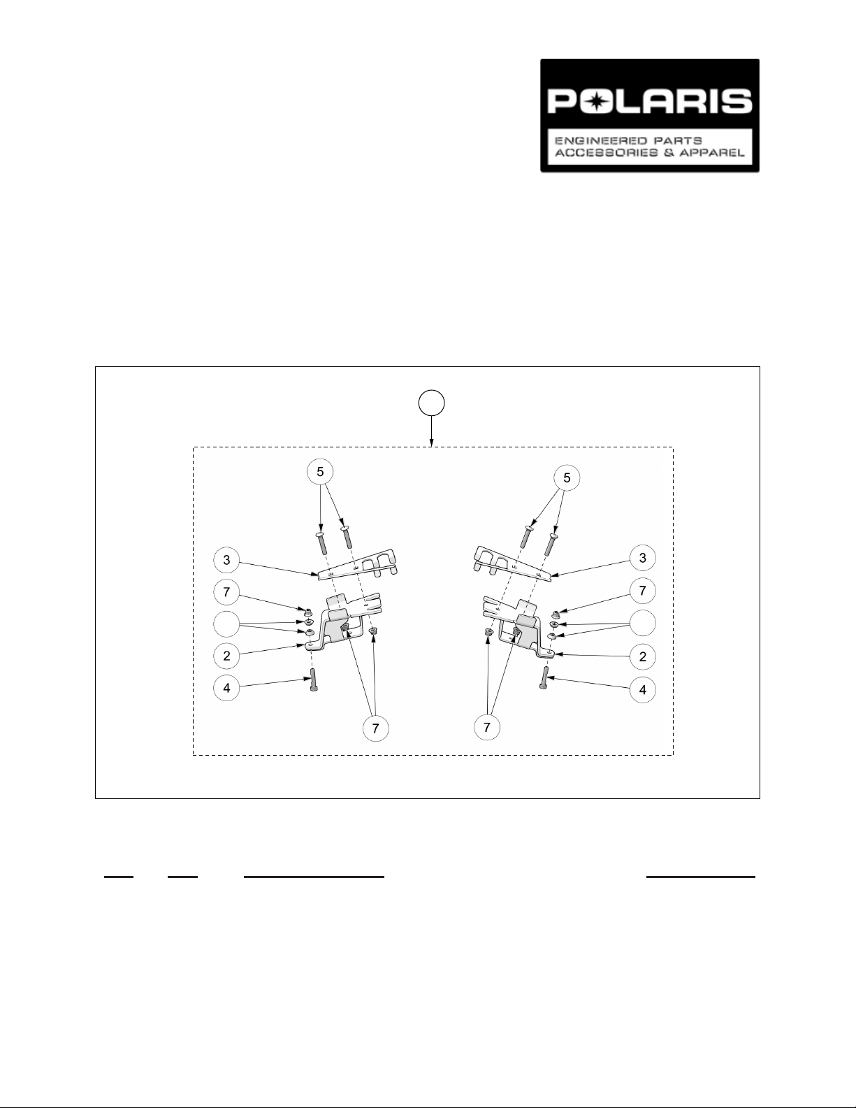
FRONT ANCHOR BRACKET:
Figure 1
Kit Contents:
Ref Qty Part Description Part Number
1 1 Front Bracket Kit 2208848
2 1 Front Anchor Bracket 3 1 Front Bracket Cover 4 2 Hex Bolt - HCS, M10-1.5X55, 10.9, ZP, DIN931 5 4 Carriage Bolt - CB, M10-1.5X60, 8.8, ZP, DIN603 6 4 Taper Sleeve 7 6 Nylon Nut - FNN, M10-1.5, 8, ZP, DIN6926 -
5000-05-9140-MAN
Page 2
-2-
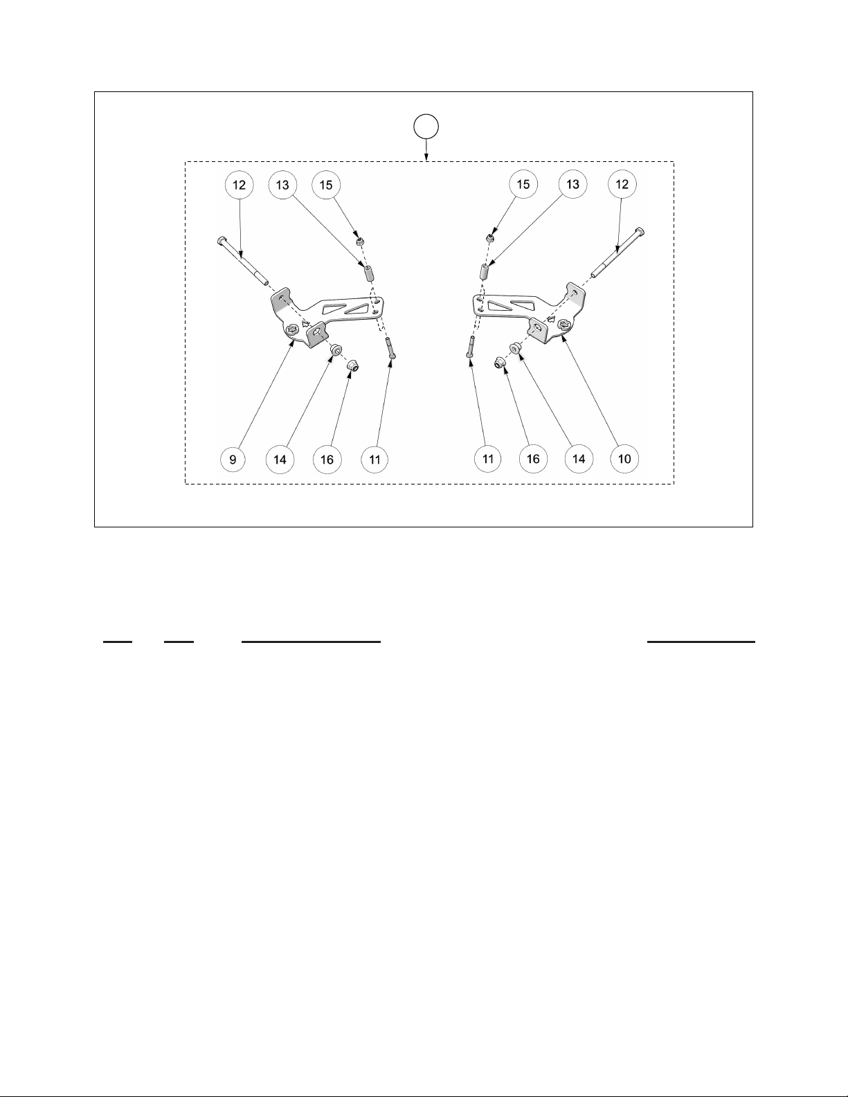
REAR ANCHOR BRACKET:
8
Figure 2
Kit Contents:
Ref Qty Part Description Part Number
8 1 Rear Bracket Kit 2208849
9 1 Rear Left Anchor Bracket 10 1 Rear Right Anchor Bracket 11 2 Hex Bolt - HCS, M8-1.25X60,10.9,ZP,DIN931 12 2 Hex Bolt - HCS, M12-1.75x190, 8.8, ZP, DIN931 13 2 Bushing 1-1/2 0.410IDX0.625ODx1.50L YZN 14 2 Taper bushing 15 2 Nylon Nut - FNN, M8-1.25,8,ZP,DIN6926 16 2 Nylon Nut - FNN, M12-1.75, 8, ZP, DIN6926 -
Page 3
-3-
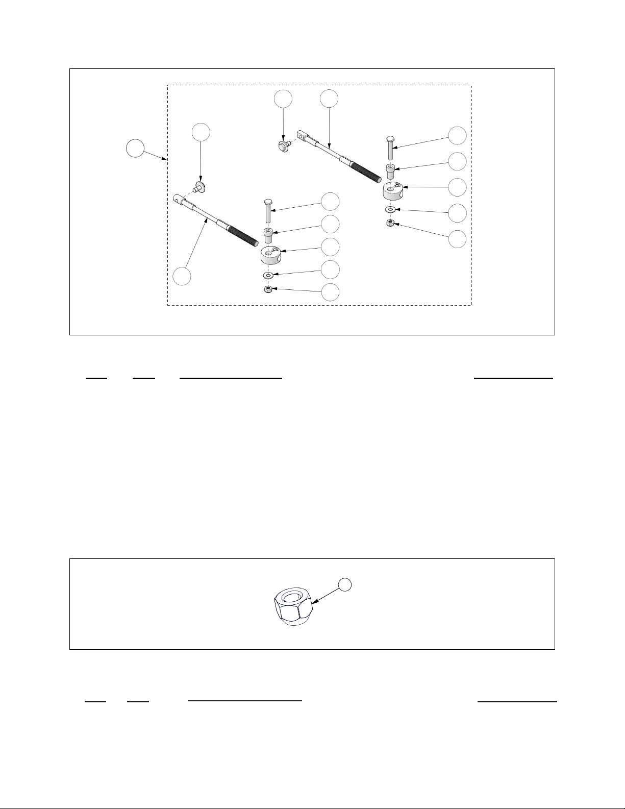
STEERING LIMITER ASSEMBLY:
17
18
18
19
19
20
19
20
21
21
22
22
23
23
24
24
Figure 3
Kit Contents:
WHEEL LUG NUT:
Kit Contents:
Ref Qty Part Description Part Number
17 1
18 2
19 2
20 2
21 2
22 2
23 2
24 2
Figure 4
Steering Limiter Cable Assembly
Steering Limiter Mounting Disk
Steering Limiter Cable
Hex Bolt - HCS, M10-1.5X60, 8.8, ZP, DIN931
Hex Bolt - HCSW, M10-1.5X25, 8.8, ZP, TL, DIN933
Step Spacer
Washer - W, 7/16X1.0X0.072, 8, ZP, USS
Nylon Nut - NN, M10-1.5, ZP, 8, DIN982
2205456
-
-
-
-
-
-
-
Ref Qty
25 16
Part Demscription
Wheel Lug Nut-LN, M12-1.5X14, 8, ZP
Part Number
2205458
Page 4
-4-
Tools Required:
Lift Table or Floor Jack Torque Wrench 2 Jack Stands
Ratchet Metric Socket Set Metric Wrench Set
APPROXIMATE ASSEMBLY TIME: 60 minutes
IMPORTANT: Please read carefully each part of this document as well as the User Manual prior to
assembling, installing and using the track systems.
INSTALLATION INSTRUCTIONS:
CAUTION: Before beginning the installation, make sure you received all the components
included in the parts lists of the preceding pages.
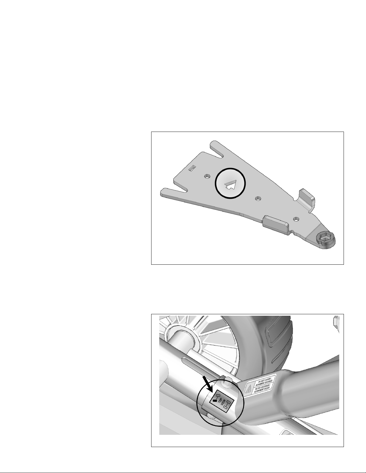
1. For installation purposes, directional
arrows have been cut out of the main
components in the anchor bracket
kits. These arrows indicate the front of
the vehicle relative to the component.
Figure 5.
Figure 5
PREPARATION:
WARNING: Never place parts of your body under the vehicle unless it is securely supported by
appropriate stands. Severe injuries could occur if the vehicle collapses or moves. Do not use a
lifting device as a secure stand.
1. Stop the vehicle on a flat and level
surface (or on a suitable lifting device),
shift the transmission into Park and
turn off engine.
2. Identify and position each unit of
the track system near the position
indicated on the sticker affixed on the
frame. Figure 6.
Figure 6
Page 5
-5-
REAR TRACK SYSTEMS:
1. Using a lifting device, raise the rear
of the vehicle and install appropriate
stands. Ensure that the vehicle is
immobilized and safe to work on.
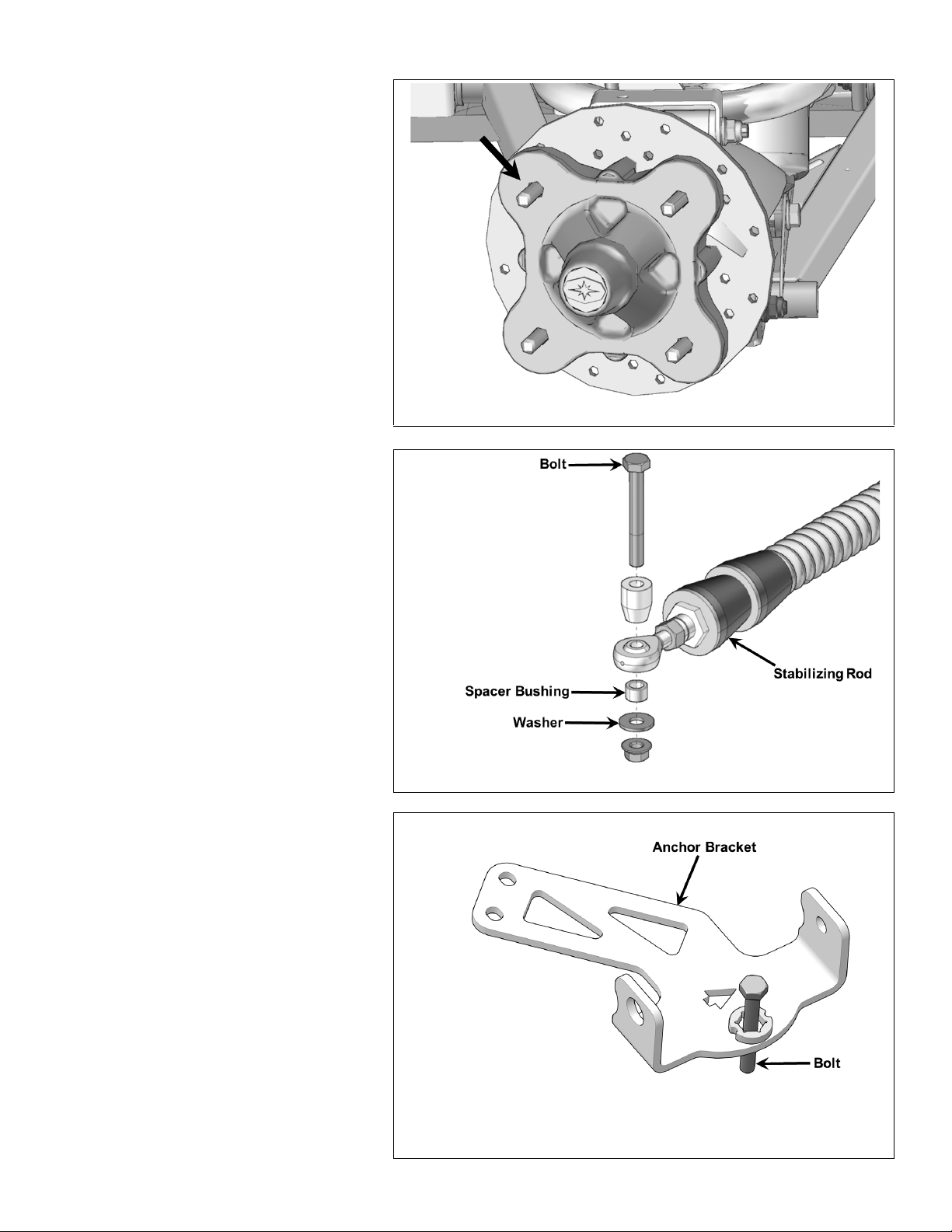
2. Remove the rear wheels to begin
Track Mount installation. Make sure
that wheel studs and wheel hubs are
free of dirt. Figure 7.
3. Remove bolt, washer and spacer
bushings from the rear stabilizing
rod end. Figure 8.
Figure 7
Figure 8
4. Insert the bolt in the rear anchor
bracket as shown in Figure 9.
NOTE: It is not possible to insert
this bolt once the bracket is attached
to the suspension arm.
Figure 9
Page 6

-6-
5. Remove bolt securing the lower
suspension arm to the wheel hub.
A new M12-1.75x190 mm bolt
provided in the installation kit
will be used to assemble the anchor
bracket, lower suspension arm and
wheel hub. Figure 10.
6. Position anchor bracket under
lower rear suspension arm.
See Figure 11 or Figure 12.
NOTE: Lower rear suspension arms
come in
depending on the vehicle
installation differs slightly for each
version.
straight or arched versions
. The bracket
Figure 10
,
Figure 11
Figure 12
Page 7

-7-
7. Align anchor bracket holes with
suspension arm holes. Install flange
bushing in bracket and suspension arm.
Slide the new M12x190 mm assembly
bolt through anchor bracket, suspension
arm, wheel hub, and flange bushing.
Thread nut on bolt but do not tighten
immediately.
See Figure 13 or Figure 14 depending
on version of suspension arm installed.
Figure 13
8. Position spacer bushing between
anchor bracket and lower suspension
arm. Align bushing with one of two holes
at the back of anchor bracket and
existing hole in suspension arm. See
Figure 15 or Figure 16.
NOTE: Bracket hole used is different
depending on version of suspension
arm installed. Straight version uses hole
nearer front of vehicle. Arched version
uses hole nearer rear of vehicle.
Figure 14
Figure 15
Page 8

-8-
8. Secure back of anchor bracket to
suspension arm with M8x60 mm bolt and
nut. Torque M12 bolt to 63 ft. lbs. (85
Nm) and M8 bolt to 18 ft. lbs. (25 Nm).
See Figure 17 or Figure 18 depending
on version of suspension arm installed.
Figure 16
Figure 17
Figure 18
Page 9

-9-
9. Secure the undercarriage to the rear hub
using the nuts (ref. #25) provided in this
mount kit. See Figure 22.
NOTE: If needed, take rubber
protector off of hub
NOTE: Ensure that the cotter pin of
the axle nut does not interfere with the
undercarriage hub.
NOTE: Torque lug nuts to 85 ft. lbs.
(115 Nm) at this time.
10. Attach the stabilizing rod to the anchor
bracket, using the long spacer bushing,
short spacer bushing,
flat washer and nut. Torque
to 52 ft. lbs. (70 Nm). Figure 23.
.
Figure 22
NOTE: Ensure that parts are
assembled in the correct order.
11. Inspect the rear track systems and
ensure that all mounting bolts were
correctly tightened during installation.
Lower the vehicle to the ground and
proceed to install the front track
systems.
Figure 23
Page 10

-10-
FRONT TRACK SYSTEMS:
1. Using a lifting device, raise the front
of the vehicle and install appropriate
stands. Ensure that the vehicle is
immobilized and safe to work on.
2. Remove front wheels to begin
Track Mount installation. Make sure
that wheel studs and wheel hubs are
free of dirt. Figure 24.
3. If applicable, remove the CV joint
protectors from the A-arms.
4. Remove and discard the bolt,
bushings, washer and nut that are
assembled on the front stabilizing
rod end. Figure 25.
Figure 24
NOTE: Lower front suspension arms
come in straight or arched versions,
depending on the vehicle
installation differs slightly for each
version. Figure 26.
. The bracket
Figure 25
Figure 26
Page 11

-11-
6. Position the bottom part of the
anchor bracket underneath the
lower suspension arm. Position
the bracket cover over the
suspension arm. Align holes
in cover with holes in bottom part.
See Figure 27 or Figure 28,
depending on version of
suspension arm installed.
Figure 27
7. Insert the M10x60 mm carriage bolts
through the bracket cover and secure
the two parts together with the nuts
provided.
See Figure 29 or Figure 30,
depending on version of
suspension arm installed.
Figure 28
Figure 29
Page 12

-12-
8. Torque assembly to 37 ft. lbs. (50 Nm).
See Figure 31 or Figure 32.
Figure 30
Figure 31
Figure 32
Page 13

-13-
9. Secure the undercarriage to the front hub
using the nuts (ref. #25) provided in this
mount kit. Figure 33.
NOTE: If needed, take rubber
protector off of hub
NOTE: Ensure that the cotter pin of
the axle nut does not interfere with the
undercarriage hub.
NOTE: Torque lug nuts to 85 ft. lbs.
(115 Nm) at this time.
.
STEERING LIMITER INSTALLATION:
10. Insert Step spacers in the Steering limiter
assemblies to get left and right steering
limiters. Figure 34.
Figure 33
NOTE: Apply grease to Step spacers
and Mounting disks before assembling
the components.
11. Attach the stabilizing rod to the
anchor bracket, using the two taper
spacers, bolt and nut. Torque to 52 ft.
lbs. (70 Nm). Figure 35.
Figure 34
Figure 35
Page 14

-14-
12. Use bolt, washer and nut to secure
Steering limiter assembly under center of
anchor bracket. Tighten nut to 37 ft. lbs.
(50 Nm). Figure 36.
NOTE:
top of assembly.
NOTE:
aluminium Mounting disk points toward
the front of the vehicle. Figure 37.
Bolt must be inserted through
Make sure the arrow on top of
Figure 36
Figure 37
Page 15

-15-
STEERING LIMITER ADJUSTMENT:
CAUTION: The angle of attack must absolutely be set before beginning steering limiter
adjustment on front track systems. Refer to the User Manual for angle of attack settings.
13. Turn the vehicle’s steering wheel to its
maximum point of travel on the left hand
side. While maintaining pressure on the
steering wheel, turn threaded rod to
adjust length of cable so that the center
of the hole at the end of the cable is
located ½ to ¾ inch [13 to 19 mm] short
of the center of the support plate
mounting hole. Figure 38.
Figure 38
14. Reverse steering wheel a little to be able
to bolt support plate and cable together.
Tighten provided bolt to 24 ft. lbs. (35
Nm). Figure 39.
Repeat steps to adjust right side.
Figure 39
COMPLETION:
1. Verify the suspension settings. If the shock absorbers are adjustable, they should be adjusted to the firmest
level to allow for maximum clearance between the track systems and the vehicle fenders.
2. Verify for possible contact between the undercarriage and the lower fender. If there is contact, the fender
should be modified (cut) to avoid damage to the vehicle’s components and premature wear on rubber track.
3. Lower the vehicle to the ground.
ADJUSTMENTS:
CAUTION: The track systems are designed to provide the best performance in terms of traction
and floatability. Adjustments such as alignment, track tension, and angle of attack are necessary
and mandatory for optimal performance of the systems. For more information on these
adjustments, refer to the USER MANUAL provided with the installation kit specific to the vehicle.
P/N 9939878 Rev 01 09/20
 Loading...