

Page 1

GENERAL INFORMATION
PartShark.com
877-999-5686
CHAPTER 1
GENERAL INFORMATION
MODEL INFORMATION . . . . . . . . . . . . . . . . . . . . . . . . . . . . . . . . . . . . . . . . . . . . . . . . . . 1.2
MODEL IDENTIFICATION . . . . . . . . . . . . . . . . . . . . . . . . . . . . . . . . . . . . . . . . . . . . . . . .1.2
ENGINE DESIGNATION NUMBER . . . . . . . . . . . . . . . . . . . . . . . . . . . . . . . . . . . . . . . . .1.2
VIN IDENTIFICATION . . . . . . . . . . . . . . . . . . . . . . . . . . . . . . . . . . . . . . . . . . . . . . . . . . .1.2
ENGINE SERIAL NUMBER LOCATION . . . . . . . . . . . . . . . . . . . . . . . . . . . . . . . . . . . . .1.2
UNIT SERIAL NUMBER (VIN) AND EMISSIONS DECAL LOCATIONS. . . . . . . . . . . . .1.3
VEHICLE INFORMATION . . . . . . . . . . . . . . . . . . . . . . . . . . . . . . . . . . . . . . . . . . . . . . . . . 1.4
PUBLICATION NUMBERS. . . . . . . . . . . . . . . . . . . . . . . . . . . . . . . . . . . . . . . . . . . . . . . .1.4
PAINT CODES . . . . . . . . . . . . . . . . . . . . . . . . . . . . . . . . . . . . . . . . . . . . . . . . . . . . . . . . .1.4
REPLACEMENT KEYS . . . . . . . . . . . . . . . . . . . . . . . . . . . . . . . . . . . . . . . . . . . . . . . . . .1.4
SPECIAL TOOLS . . . . . . . . . . . . . . . . . . . . . . . . . . . . . . . . . . . . . . . . . . . . . . . . . . . . . . . 1.4
GENERAL SPECIFICATIONS. . . . . . . . . . . . . . . . . . . . . . . . . . . . . . . . . . . . . . . . . . . . . . 1.5
MODEL: 2009 RANGER RZR 170 . . . . . . . . . . . . . . . . . . . . . . . . . . . . . . . . . . . . . . . . . .1.6
MISC. SPECIFICATIONS AND CHARTS . . . . . . . . . . . . . . . . . . . . . . . . . . . . . . . . . . . . . 1.7
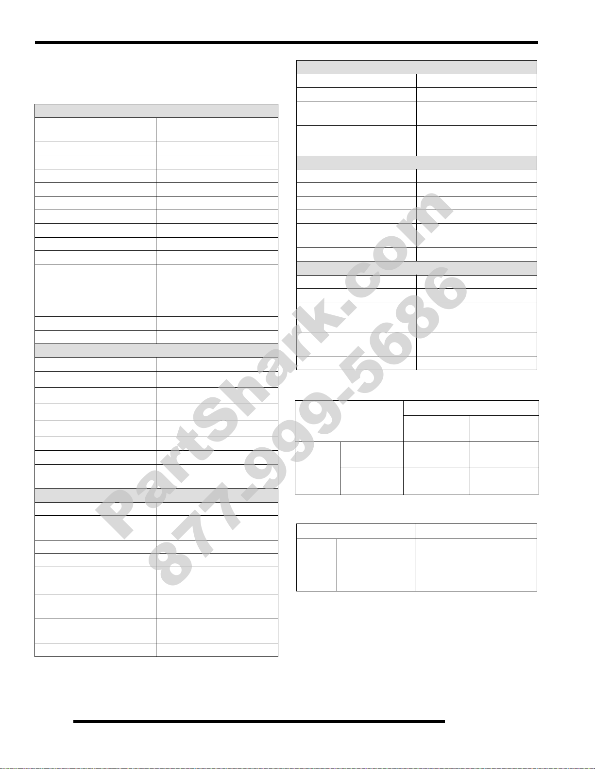
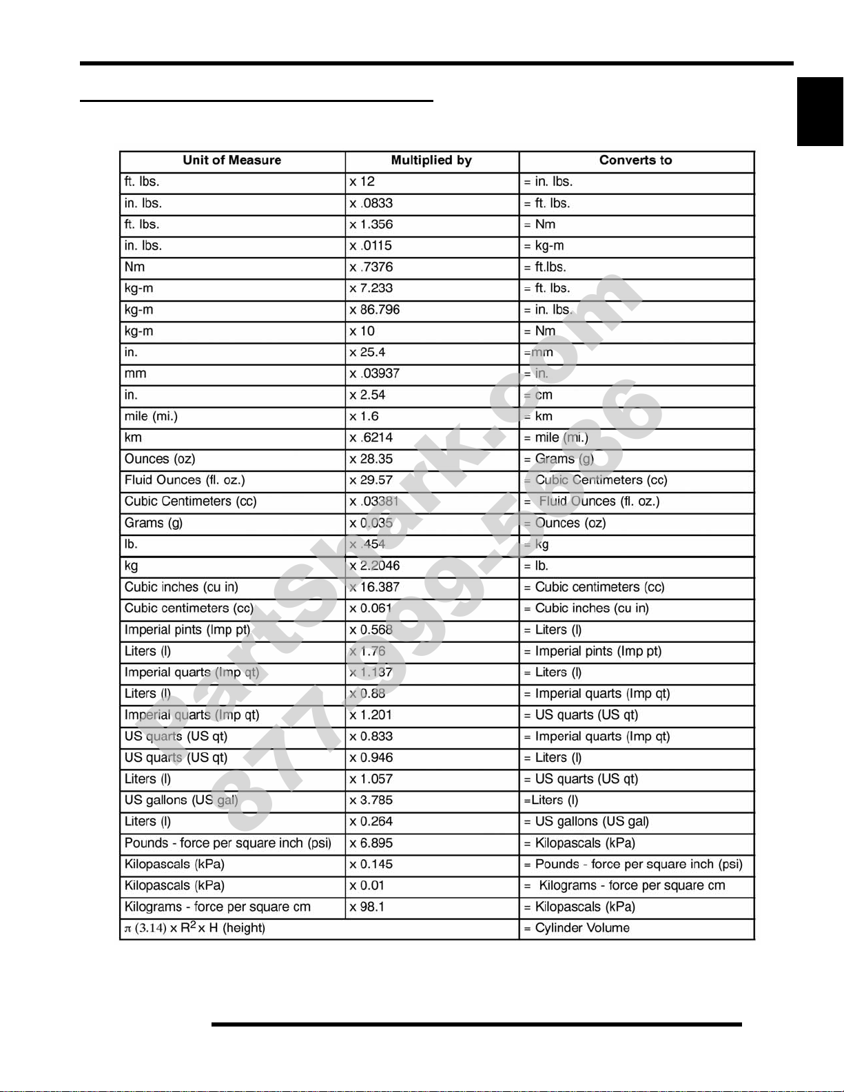
CONVERSION TABLE. . . . . . . . . . . . . . . . . . . . . . . . . . . . . . . . . . . . . . . . . . . . . . . . . . .1.7
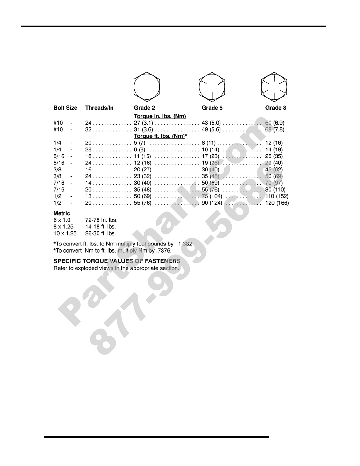
STANDARD TORQUE SPECIFICATIONS. . . . . . . . . . . . . . . . . . . . . . . . . . . . . . . . . . . .1.8
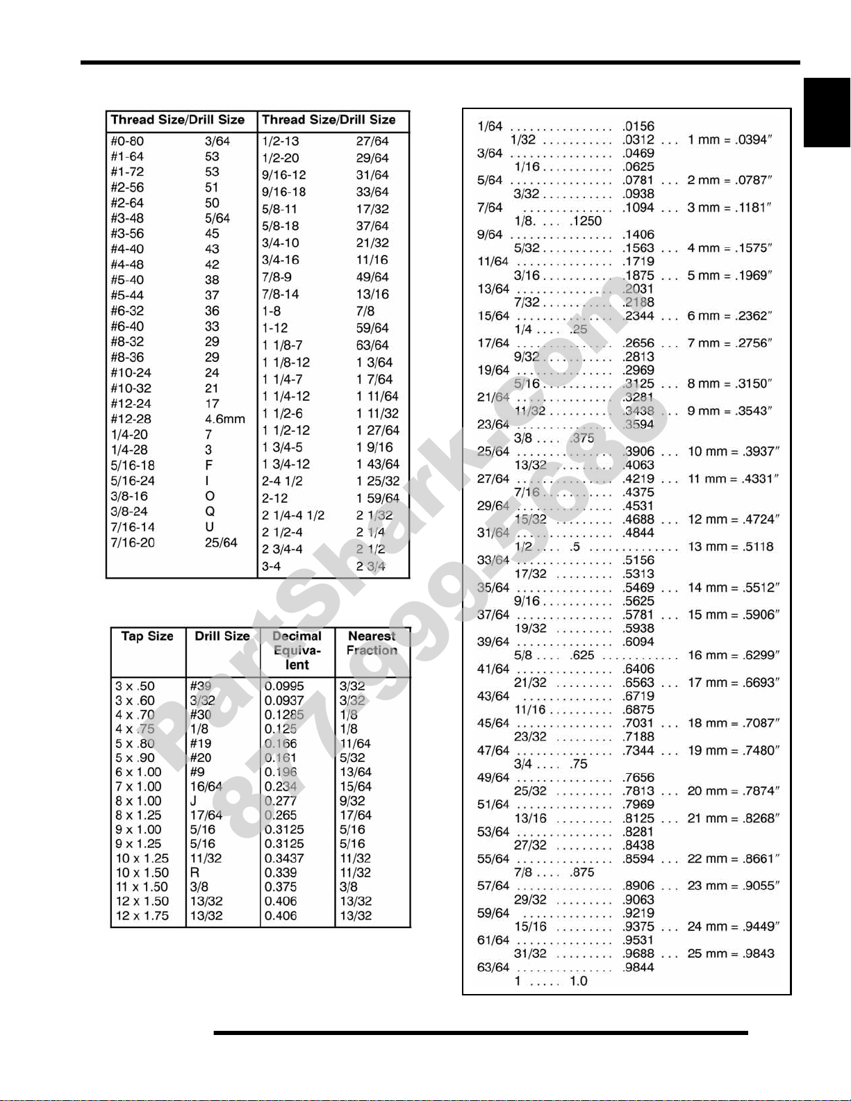
SAE TAP / DRILL SIZES . . . . . . . . . . . . . . . . . . . . . . . . . . . . . . . . . . . . . . . . . . . . . . . . .1.9
METRIC TAP / DRILL SIZES . . . . . . . . . . . . . . . . . . . . . . . . . . . . . . . . . . . . . . . . . . . . . .1.9
DECIMAL EQUIVALENTS . . . . . . . . . . . . . . . . . . . . . . . . . . . . . . . . . . . . . . . . . . . . . . . .1.9
GLOSSARY OF TERMS. . . . . . . . . . . . . . . . . . . . . . . . . . . . . . . . . . . . . . . . . . . . . . . . .1.10
1
1.1
Page 2
GENERAL INFORMATION
}
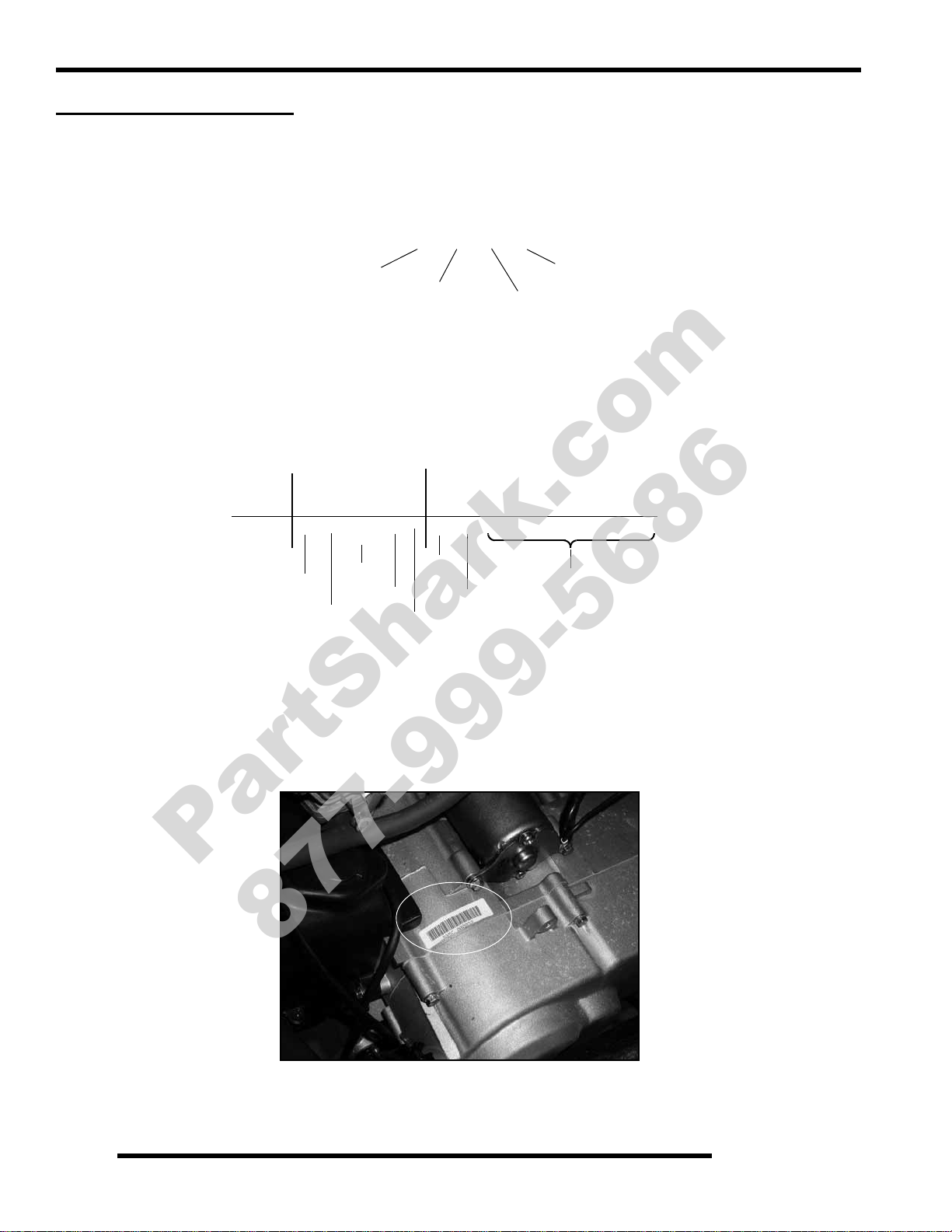
Machine Model Number Identification
}
}
Model Year
Designation
Basic Chassis
Designation
Engine Designation
Emissions &
Model Option
R 0 9 V A 1 7 A D
}
4 X A V A 1 7 A * 9 P 0 0 0 0 0 0
}
1 2 3 4 5 6 7 8 9 10 11 12 13 14 15 16 17
World
Mfg. ID
Engine
Vehicle Description
Vehicle Identifier
Check Digit
Model
Year
Body Style
Plant No.
Individual Serial No.
* This could be either
a number or a letter
Powertrain
Emissions
ENGINE SERIAL NUMBER
PartShark.com
877-999-5686
MODEL INFORMATION
Model Identification
The machine model number must be used with any correspondence regarding warranty or service.
Engine Designation Number
S35C.................................................................................................Single Cylinder, Air/Oil Cooled, OHV 4 Stroke, Electric Start
VIN Identification
Engine Serial Number Location
Whenever corresponding about an engine, be sure to refer to the engine model number and serial number. This information can be
found on the sticker applied to the clutch-side engine case.
1.2
Page 3
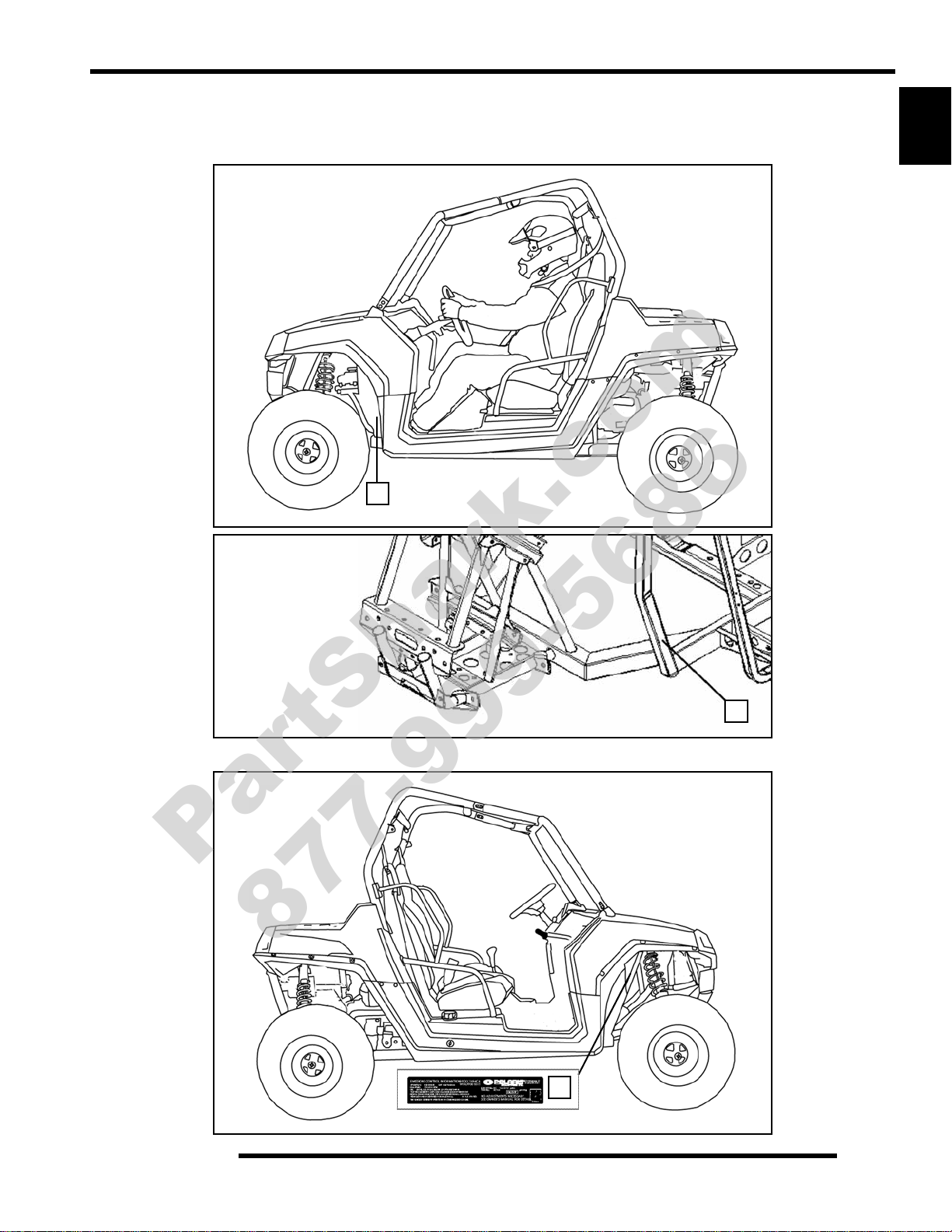
Unit Serial Number (VIN) and Emissions Decal Locations
A
B
C
PartShark.com
877-999-5686
GENERAL INFORMATION
The machine model information decal (A) and vehicle identification number (VIN) are important for identification. The VIN number
(B) is stamped on a portion of the front left frame rail close to the left front wheel.
1
The engine emissions decal (C) is attached to the frame support, accessible through the front right wheel well.
1.3
Page 4
GENERAL INFORMATION
P/N 0453013
PartShark.com
877-999-5686
VEHICLE INFORMATION
Publication Numbers
Model Model No. Owner’s Manual PN Parts Manual PN
2009 RANGER RZR 170 R09VA17AA
NOTE: When orderi ng se rvice part s be sure to use the correct parts manual.
NOTE: Polaris factory publications can be found at www.polarisindustries.com or purchased from
www.purepolaris.com.
Paint Codes
Painted Part Color Description Polaris Number
Frame / Bumpers / Racks Gloss Black P-067
Plastic - Hood / Dash / Fenders Indy Red P-293
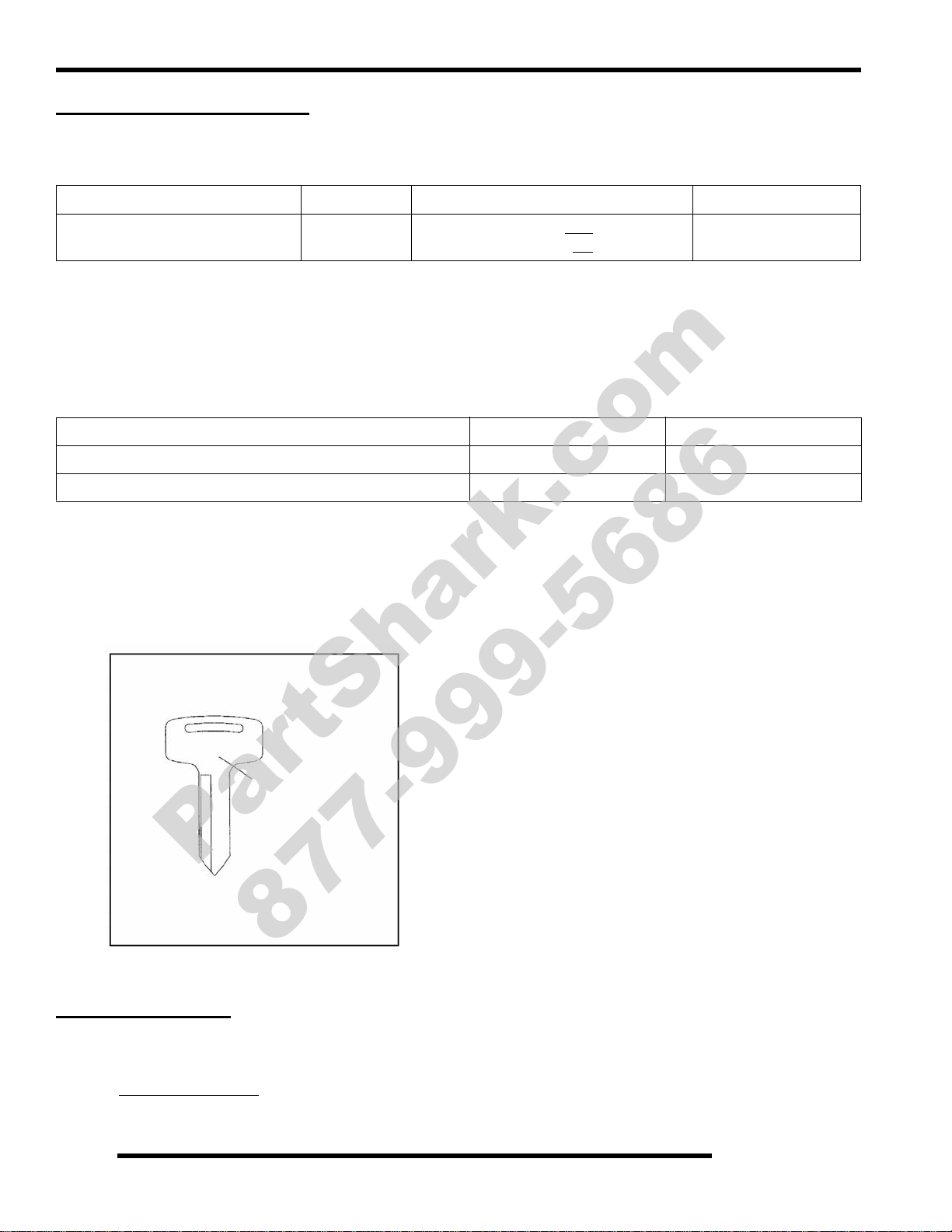
Replacement Keys
Replacement keys can be made from the original key . Polaris offers replacement key blanks (0453013) that can be cut to match the
original. Should both keys become lost, ignition switch replacement is required.
9922131
9922569 (produced after 2/10/2009)
(produced before 2/10/2009)
9922132
SPECIAL TOOLS
Special tools may be required while servicing this vehicle. Some of the tools listed or depicted are mandatory, while other tools
maybe substituted with a similar tool, if available. Polaris recommends the use of Polaris Special Tools when servicing any Polaris
product. Dealers may order special tools through Polaris’ official tool supplier, SPX Corporation, by phone at 1-800-328-6657 or
on-line at http://polaris.spx.com/
.
1.4
Page 5
GENERAL SPECIFICATIONS
PartShark.com
877-999-5686
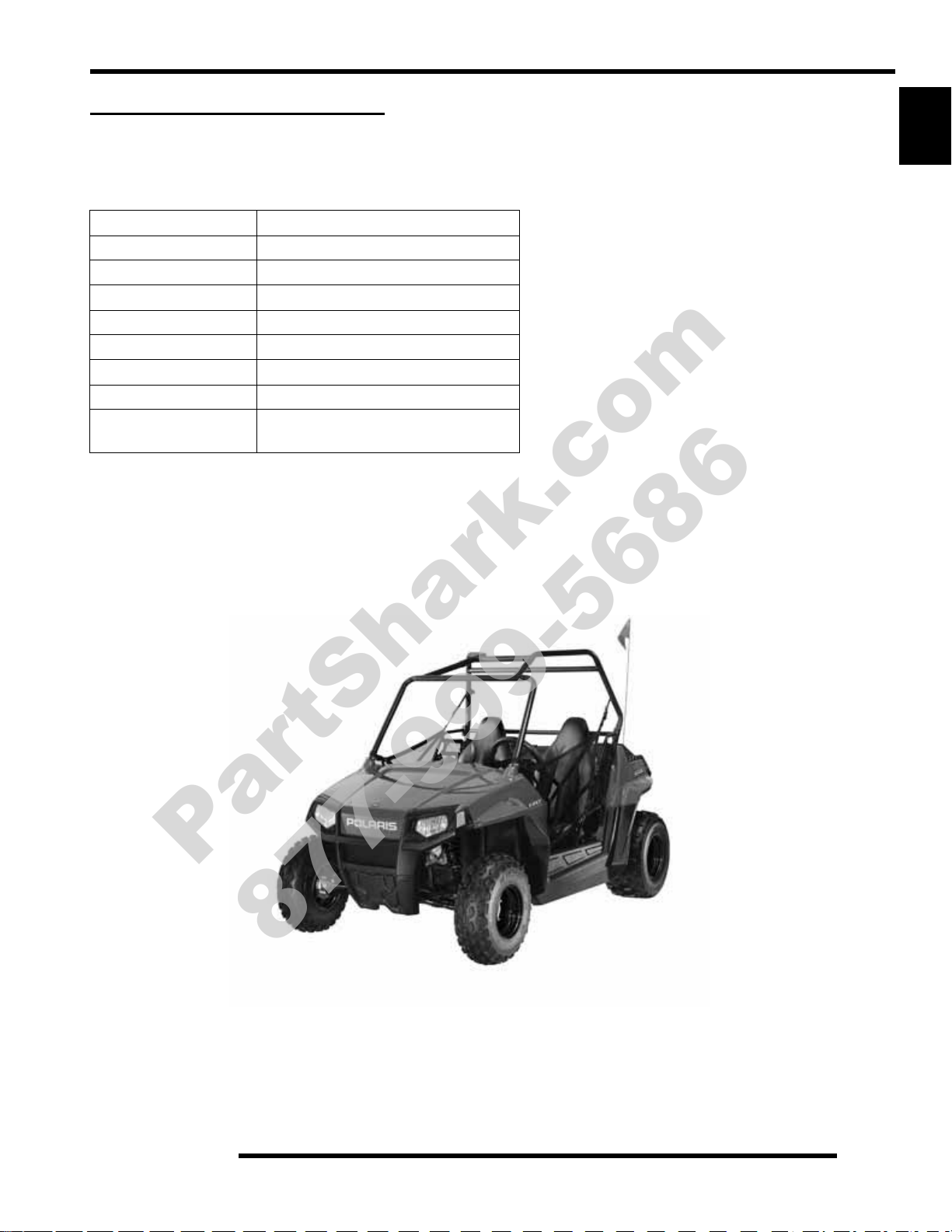
MODEL: 2009 RANGER RZR 170
MODEL NUMBER: R09VA17AA
ENGINE MODEL: S35C
Category Dimension / Capacity
Length 85 in. / 216 cm
Width 48 in. / 122 cm
Height 55 in. / 139.7 cm
Wheel Base 65 in. / 165 cm
Ground Clearance 6 in. / 15.2 cm
Dry Weight 500 lbs. / 227 kg
Gross Vehicle Weight 840 lbs. / 381 kg
Maximum Weight
Capacity
(Includes people, cargo, accessories)
300 lbs. / 81.7 kg
GENERAL INFORMATION
1
1.5
Page 6
GENERAL INFORMATION
PartShark.com
877-999-5686
MODEL: 2009 RANGER RZR 170
MODEL NUMBER: R09VA17AA
ENGINE MODEL: S35C
Engine
Platform
Engine Model Number S35C
Engine Displacement 169cc
Number of Cylinders 1
Bore & Stroke (mm) 61 x 57.8 mm
Compression Ratio 9.5:1
Compression Pressure 130-160 psi @ W.O.T.
Engine Idle Speed 1700 ± 100 RPM
Engine Max Operating RPM 8000 ± 200 RPM
Lubrication Wet Sump
Oil Requirements
Oil Capacity 37 oz.. / 1.1 liters
Exhaust System Single Headpipe / Single Silencer
Carburetor Type Keihin
Pilot Jet 35
Main Jet 100
Air Screw 2 1/4 Turns Out (initial)
Jet Needle 2MKNN - #4 clip position
Fuel Delivery Fuel Pump
Fuel Filters See Chapter 4
Fuel Capacity / Requirement
Alternator Max Output 80 Watts @ 3000 RPM
Lights: Main Headlights
Tail / Brake 5 Watts / 21 Watts
Starting System Electric Start
Ignition System CDI
Ignition Timing Non-Adjustable
Spark plug / Gap
Battery
Fuses Main: 20 Amp
Single Cylinder, Air/Oil Cooled
4-Stroke
Above 32° F
Polaris ‘YOUTH’ oil
Below 32° F ( 0° C
20W-40 oil
Fuel System
2.5 gal. (9.5 liters)
87 Octane (minimum)
Electrical
2 - Single Beam
Daytime Running Lamps (DRL)
NGK CR6HSA
.024-.028 in. (0.6-0.7 mm)
GTX12-BS / Low Maintenence
12 Amp Hr. / 12 Volt
( 0° C )
)
Drivetrain
Transmission Type Polaris Automatic CVT
Shift Type In Line Shift - H / N / R
Transmission Oil Requirements
Main Gearcase
Drive Belt 0454497
Drive Chain - Type / # Links
Steering / Suspension
Front Suspension Single A-arm
Front Travel 5 in. / 12.7 cm
Rear Suspension Dual Shock Swingarm
Rear Travel 5 in. / 12.7 cm
Shock Preload Adjustment
Front / Rear
Toe Out 1/8-1/4 in. / 3-6.35 mm
Wheels / Brakes
Front Tire Size 19 x 7 - 8
Rear Tire Size 20 x 10 - 9
Bolt Pattern
Tire Air Pressure - Front / Rear 3 psi (20.7 kPa)
Brake - Front / Rear
Brake Fluid DOT 4
JETTING CHART
Altitude
0-3048
Meters
(Feet)
CLUTCH CHART
Meters
(Feet)
***15 gram weights are optional and are not a High Altitude
(H.A.) Warranty item.
(0-10000)
Above 3048
(Above 10,000)
Altitude Shift W e ight
0-3048
(0-10,000)
Above 3048
(Above 10,000)
Below 40 F
Below 5
Polaris AGL
23.7 oz. (700 ml)
520 / 30
Cam Adjustable
(Factory Setting - Softest)
110mm
Foot Actuated - 4 Wheel
Hydraulic Disc
Ambient Temperature
Above +40
C
102 100
100
6 @ 17 grams
*** 6 @ 15 grams
Above +5
98
#3 needle clip position
PN 0454619
F
C
1.6
Page 7
MISC. SPECIFICATIONS AND CHARTS
PartShark.com
877-999-5686
Conversion Table
GENERAL INFORMATION
1
°C to °F:
9/5
(°C + 32) = °F °F to °C:
5/9
(°F - 32) = °C
1.7
Page 8
GENERAL INFORMATION
PartShark.com
877-999-5686
Standard Torque Specifications
The following torque specifications are to be used only as a general guideline. There are exceptions in the steering, suspension, and
engine areas. Always consult the exploded views or each manual section for torque values of fasteners before using standard torque.
1.8
Page 9
GENERAL INFORMATION
PartShark.com
877-999-5686
SAE Tap / Drill Sizes
Decimal Equivalents
1
Metric Tap / Drill Sizes
1.9
Page 10

GENERAL INFORMATION
PartShark.com
877-999-5686
Glossary of Terms
ABDC: After bottom dead center.
ACV: Alternating current voltage.
Alternator: Electrical generator producing voltage alternating current.
ATDC: After top dead center.
BBDC: Before bottom dead center.
BDC: Bottom dead center.
BTDC: Before top dead center.
CC: Cubic centimeters.
Center Distance: Distance between center of crankshaft and center of driven clutch shaft.
Chain Pitch: Distance between chain link pins (No. 35 = 3/8" or 1 cm).
CI: Cubic inches.
Clutch Buttons: Plastic bushings which aid rotation of the movable sheave in the drive and driven clutch.
Clutch Offset: Drive and driven clutches are offset so that drive belt will stay nearly straight as it moves along the clutch face.
Clutch Weights: Rollers in the drive clutch which relative to their weight, profile and engine RPM cause the drive clutch to close
and grip the drive belt.
Crankshaft Run-Out: Run-out or "bend" of crankshaft measured with a dial indicator while crankshaft is supported between centers
on V blocks or resting in crankcase. Measure at various points especially at PTO.
DCV: Direct current voltage
CVT: Centrifugal Variable Transmission (Drive Clutch System)
DCV: Direct current voltage.
Dial Bore Gauge: A cylinder measuring instrument which uses a dial indicator. Good for showing taper and out-of-round in t he
cylinder bore.
Electrical Open: Open circuit. An electrical circuit which isn't complete.
Electrical Short: Short circuit. An electrical circuit which is completed before the current reaches the intended load. (i.e. a bare wire
touching the chassis).
End Seals: Rubber seals at each end of the crankshaft.
Engagement RPM: Engine RPM at which the drive clutch engages to make contact with the drive belt.
ft.: Foot/feet.
Foot Pound: Ft. lb. A force of one pound at the end of a lever one foot in length, applied in a rotational direction.
g: Gram. Unit of weight in the metric system.
gal.: Gallon.
ID: Inside diameter.
in.: Inch/inches.
Inch Pound: In. lb. 12 in. lbs. = 1 ft. lb.
kg/cm²: Kilograms per square centimeter.
kg-m: Kilogram meters.
Kilogram/meter: A force of one kilogram at the end of a lever one meter in length, applied in a rotational direction.
l or ltr: Liter.
lbs/in²: Pounds per square inch.
Left or Right Side: Always referred to based on normal operating posit ion of the driver.
m: Meter/meters.
Mag: Magneto.
Magnetic Induction: As a conductor (coil) is moved through a magnetic field, a voltage will be generated in the windings.
Mechanical energy is converted to electrical energy in the stator.
mi.: Mi
mm: Millimeter. Unit of length in the metric system. 1 mm = approximately .040".
Nm: Newton meters.
OD: Outside diameter.
Ohm: The unit of electrical resistance opposing current flow.
oz.: Ounce/ounces.
Piston Clearance: Total distance between piston and cylinder wall.
psi.: Pounds per square inch.
PTO: Power take off.
PVT: Polaris Variable Transmission (Drive Clutch system)
qt.: Quart/quarts.
Regulator: Voltage regulator. Regulates battery charging system output at approx. 14.5 DCV as engine RPM increases.
Reservoir Tank: The fill tank in the liquid cooling system.
Resistance: In the mechanical sense, friction or load. In the electrical sense, ohms, resulting in energy conversion to heat.
RPM: Revolutions per minute.
Seized Piston: Galling of the sides of a piston. Usually there is a transfer of aluminum from the piston onto the cylinder wall.
Possible causes: 1) improper lubrication; 2) excessive temperatures; 3) insufficient piston clearance; 4) stuck piston rings.
Stator Plate: The plate mounted under the flywheel supporting the battery charging coils.
TDC: Top dead center. Piston's most outward travel from crankshaft .
Volt: The unit of measure for electrical pressure of electromotive force. Measured by a voltmeter in parallel with the circuit.
Watt: Unit of electrical power. Watts = amperes x volts.
WOT: Wide open throttle.
le/miles.
1.10
Page 11

MAINTENANCE
PartShark.com
877-999-5686
CHAPTER 2
MAINTENANCE
PERIODIC MAINTENANCE CHART . . . . . . . . . . . . . . . . . . . . . . . . . . . . . . . . . . . . . . . . 2.3
PERIODIC MAINTENANCE OVERVIEW. . . . . . . . . . . . . . . . . . . . . . . . . . . . . . . . . . . . .2.3
MAINTENANCE CHART KEY . . . . . . . . . . . . . . . . . . . . . . . . . . . . . . . . . . . . . . . . . . . . .2.3
PRE-RIDE - 25 HOUR MAINTENANCE INTERVAL . . . . . . . . . . . . . . . . . . . . . . . . . . . .2.4
30 - 100 HOUR MAINTENANCE INTERVAL. . . . . . . . . . . . . . . . . . . . . . . . . . . . . . . . . .2.5
MAINTENANCE REFERENCES / SERVICE LOCATIONS. . . . . . . . . . . . . . . . . . . . . . . . 2.6
FRONT AND REAR VIEW . . . . . . . . . . . . . . . . . . . . . . . . . . . . . . . . . . . . . . . . . . . . . . . .2.6
RH AND LH SIDE VIEWS. . . . . . . . . . . . . . . . . . . . . . . . . . . . . . . . . . . . . . . . . . . . . . . . .2.7
LUBRICANTS / SERVICE PRODUCTS . . . . . . . . . . . . . . . . . . . . . . . . . . . . . . . . . . . . . . 2.8
MAINTENANCE REFERENCES. . . . . . . . . . . . . . . . . . . . . . . . . . . . . . . . . . . . . . . . . . . . 2.9
GENERAL VEHICLE INSPECTION AND MAINTENANCE. . . . . . . . . . . . . . . . . . . . . . . 2.10
PRE-RIDE / DAILY INSPECTION . . . . . . . . . . . . . . . . . . . . . . . . . . . . . . . . . . . . . . . . .2.10
FRAME, NUTS, BOLTS, AND FASTENERS . . . . . . . . . . . . . . . . . . . . . . . . . . . . . . . . .2.10
SHIFT CABLE INSPECTION / ADJUSTMENT. . . . . . . . . . . . . . . . . . . . . . . . . . . . . . . .2.10
SHIFT CABLE REPLACEMENT. . . . . . . . . . . . . . . . . . . . . . . . . . . . . . . . . . . . . . . . . . .2.11
FUEL SYSTEM AND AIR INTAKE . . . . . . . . . . . . . . . . . . . . . . . . . . . . . . . . . . . . . . . . . 2.12
AIR FILTER SERVICE . . . . . . . . . . . . . . . . . . . . . . . . . . . . . . . . . . . . . . . . . . . . . . . . . .2.12
CHOKE CABLE ADJUSTMENT. . . . . . . . . . . . . . . . . . . . . . . . . . . . . . . . . . . . . . . . . . .2.13
CHOKE CABLE REPLACEMENT . . . . . . . . . . . . . . . . . . . . . . . . . . . . . . . . . . . . . . . . .2.13
IDLE SPEED ADJUSTMENT . . . . . . . . . . . . . . . . . . . . . . . . . . . . . . . . . . . . . . . . . . . . .2.14
PILOT AIR SCREW ADJUSTMENT. . . . . . . . . . . . . . . . . . . . . . . . . . . . . . . . . . . . . . . .2.14
VENT LINES. . . . . . . . . . . . . . . . . . . . . . . . . . . . . . . . . . . . . . . . . . . . . . . . . . . . . . . . . .2.15
FUEL SYSTEM. . . . . . . . . . . . . . . . . . . . . . . . . . . . . . . . . . . . . . . . . . . . . . . . . . . . . . . .2.15
FUEL FILTER. . . . . . . . . . . . . . . . . . . . . . . . . . . . . . . . . . . . . . . . . . . . . . . . . . . . . . . . .2.15
FUEL VALVE LOCATION. . . . . . . . . . . . . . . . . . . . . . . . . . . . . . . . . . . . . . . . . . . . . . . .2.16
CARBURETOR DRAINING . . . . . . . . . . . . . . . . . . . . . . . . . . . . . . . . . . . . . . . . . . . . . .2.16
FUEL PUMP / FUEL LINES . . . . . . . . . . . . . . . . . . . . . . . . . . . . . . . . . . . . . . . . . . . . . .2.16
THROTTLE PEDAL INSPECTION. . . . . . . . . . . . . . . . . . . . . . . . . . . . . . . . . . . . . . . . .2.17
THROTTLE STOP SPEED CONTROL . . . . . . . . . . . . . . . . . . . . . . . . . . . . . . . . . . . . .2.17
THROTTLE FREEPLAY ADJUSTMENT . . . . . . . . . . . . . . . . . . . . . . . . . . . . . . . . . . . .2.18
THROTTLE CABLE REPLACEMENT . . . . . . . . . . . . . . . . . . . . . . . . . . . . . . . . . . . . . .2.18
ENGINE. . . . . . . . . . . . . . . . . . . . . . . . . . . . . . . . . . . . . . . . . . . . . . . . . . . . . . . . . . . . . . 2.20
ENGINE OIL LEVEL. . . . . . . . . . . . . . . . . . . . . . . . . . . . . . . . . . . . . . . . . . . . . . . . . . . .2.20
ENGINE OIL CHANGE. . . . . . . . . . . . . . . . . . . . . . . . . . . . . . . . . . . . . . . . . . . . . . . . . .2.20
ENGINE CRANKCASE VENTILATION SYSTEM INSPECTION . . . . . . . . . . . . . . . . . .2.21
ENGINE/TRANSMISSION MOUNT LOCATIONS . . . . . . . . . . . . . . . . . . . . . . . . . . . . .2.21
COMPRESSION / LEAKDOWN TEST. . . . . . . . . . . . . . . . . . . . . . . . . . . . . . . . . . . . . .2.22
INTAKE VALVE CLEARANCE ADJUSTMENT . . . . . . . . . . . . . . . . . . . . . . . . . . . . . . .2.22
EXHAUST VALVE CLEARANCE ADJUSTMENT . . . . . . . . . . . . . . . . . . . . . . . . . . . . .2.22
EXHAUST - SPARK ARRESTOR. . . . . . . . . . . . . . . . . . . . . . . . . . . . . . . . . . . . . . . . . .2.23
TRANSMISSION . . . . . . . . . . . . . . . . . . . . . . . . . . . . . . . . . . . . . . . . . . . . . . . . . . . . . . . 2.24
TRANSMISSION SPECIFICATION CHART. . . . . . . . . . . . . . . . . . . . . . . . . . . . . . . . . .2.24
TRANSMISSION OIL CHANGE. . . . . . . . . . . . . . . . . . . . . . . . . . . . . . . . . . . . . . . . . . .2.24
FINAL DRIVE / WHEEL AND TIRE. . . . . . . . . . . . . . . . . . . . . . . . . . . . . . . . . . . . . . . . . 2.25
WHEEL, HUB, AND SPINDLE TORQUE TABLE. . . . . . . . . . . . . . . . . . . . . . . . . . . . . .2.25
WHEEL REMOVAL. . . . . . . . . . . . . . . . . . . . . . . . . . . . . . . . . . . . . . . . . . . . . . . . . . . . .2.25
WHEEL INSTALLATION. . . . . . . . . . . . . . . . . . . . . . . . . . . . . . . . . . . . . . . . . . . . . . . . .2.25
TIRE INSPECTION. . . . . . . . . . . . . . . . . . . . . . . . . . . . . . . . . . . . . . . . . . . . . . . . . . . . .2.26
TIRE PRESSURE. . . . . . . . . . . . . . . . . . . . . . . . . . . . . . . . . . . . . . . . . . . . . . . . . . . . . .2.26
DRIVE CHAIN LUBRICATION AND ADJUSTMENT . . . . . . . . . . . . . . . . . . . . . . . . . . .2.26
2
2.1
Page 12

MAINTENANCE
PartShark.com
877-999-5686
ELECTRICAL AND IGNITION SYSTEM. . . . . . . . . . . . . . . . . . . . . . . . . . . . . . . . . . . . . 2.27
BATTERY MAINTENANCE . . . . . . . . . . . . . . . . . . . . . . . . . . . . . . . . . . . . . . . . . . . . . . 2.27
BATTERY REMOVAL. . . . . . . . . . . . . . . . . . . . . . . . . . . . . . . . . . . . . . . . . . . . . . . . . . . 2.28
BATTERY INSTALLATION. . . . . . . . . . . . . . . . . . . . . . . . . . . . . . . . . . . . . . . . . . . . . . .2.28
BATTERY OFF SEASON STORAGE . . . . . . . . . . . . . . . . . . . . . . . . . . . . . . . . . . . . . .2.28
BATTERY CHARGING (MAINTENANCE FREE). . . . . . . . . . . . . . . . . . . . . . . . . . . . . .2.28
SPARK PLUG SERVICE . . . . . . . . . . . . . . . . . . . . . . . . . . . . . . . . . . . . . . . . . . . . . . . . 2.29
ENGINE TO FRAME GROUND . . . . . . . . . . . . . . . . . . . . . . . . . . . . . . . . . . . . . . . . . . . 2.29
STEERING . . . . . . . . . . . . . . . . . . . . . . . . . . . . . . . . . . . . . . . . . . . . . . . . . . . . . . . . . . . 2.30
STEERING INSPECTION . . . . . . . . . . . . . . . . . . . . . . . . . . . . . . . . . . . . . . . . . . . . . . . 2.30
STEERING WHEEL FREEPLAY . . . . . . . . . . . . . . . . . . . . . . . . . . . . . . . . . . . . . . . . . . 2.30
STEERING INSPECTION / TIE ROD ENDS AND HUBS . . . . . . . . . . . . . . . . . . . . . . . 2.30
TOE ALIGNMENT INSPECTION . . . . . . . . . . . . . . . . . . . . . . . . . . . . . . . . . . . . . . . . . .2.31
TOE ADJUSTMENT. . . . . . . . . . . . . . . . . . . . . . . . . . . . . . . . . . . . . . . . . . . . . . . . . . . .2.31
SUSPENSION. . . . . . . . . . . . . . . . . . . . . . . . . . . . . . . . . . . . . . . . . . . . . . . . . . . . . . . . . 2.32
SPRING PRELOAD ADJUSTMENT. . . . . . . . . . . . . . . . . . . . . . . . . . . . . . . . . . . . . . . .2.32
BRAKE SYSTEM. . . . . . . . . . . . . . . . . . . . . . . . . . . . . . . . . . . . . . . . . . . . . . . . . . . . . . . 2.32
BRAKE FLUID INSPECTION. . . . . . . . . . . . . . . . . . . . . . . . . . . . . . . . . . . . . . . . . . . . .2.32
BRAKE PAD / DISC INSPECTION. . . . . . . . . . . . . . . . . . . . . . . . . . . . . . . . . . . . . . . . . 2.33
BRAKE HOSE AND FITTING INSPECTION . . . . . . . . . . . . . . . . . . . . . . . . . . . . . . . . . 2.33
MAINTENANCE LOG . . . . . . . . . . . . . . . . . . . . . . . . . . . . . . . . . . . . . . . . . . . . . . . . . . . 2.34
2.2
Page 13
MAINTENANCE
WARNING
PartShark.com
877-999-5686
PERIODIC MAINTENANCE CHART
Periodic Maintenance Overview
Careful periodic maintenance will help keep your vehicle in the safest, most reliable condition. Inspection, adjustment
and lubrication of important components ar e explained in the periodic maintenance chart.
Inspect, clean, lubricate, adjust and replace parts as necessary. When inspection reveals the need for replacement
parts, use genuine Polaris parts available from your Polaris dealer.
NOTE: Service and adjustments are critical. If you’re not familiar with safe service and adjustment procedures, have a
qualified dealer perform these operatio ns .
Maintenance intervals in the following chart are based upon average riding conditions and an average vehicle speed
of approximately 10 miles per hour. Vehicles subjected to severe use must be inspected and serviced more frequently .
Severe Use Definition
• Frequent immersion in mud, water or sand
• Racing or race-style high RPM use
• Prolonged low speed, heavy load operation
• Extended idle
• Short trip cold weather operation
Pay special attention to the oil level. A rise in oil level during cold weather can ind icate contaminants collecting in the
oil sump or crankcase. Change oil immediately if the oil level begins to rise. Monitor the oil level, and if it continues to
rise, discontinue use and determine th e cau se or se e you r dea ler.
Maintenance Chart Key
The following symbols denote potential items to be aware of during maintenance :
2
= CAUTION: Due to the nature of these adjustments, it is recommended this service be performed by an
authorized Polaris dealer.
= SEVERE USE ITEM -- See Above
E = Emission Control System Service (California).
NOTE: Inspection may reveal the need for replacement parts. Always use genuine Polaris parts.
Improperly performing the procedures marked with acould
result in component failure and lead to serious injury or death.
Have an authorized Polaris dealer perform these services.
2.3
Page 14
MAINTENANCE
PartShark.com
877-999-5686
Pre-Ride - 25 Hour Maintenance Interval
Periodic Maintenance Chart
Maintenance Interval
Item
Steering - Daily -
Front-Suspension - Daily -
Rear-Suspension - Daily -
Tires - Daily Brake Pedal Travel - Daily -
Brake Fluid Level - Daily Daytime Running Lights - Daily Drive Chain - Daily Brake Lamp / Tail Lamp - Daily Throttle - Daily Wheels / Fasteners - Daily Frame Fasteners - Daily -
Engine Oil Level - Daily -
E
Fuel Level - Daily -
Air Filter (main element) - Daily - Inspect; clean often, replace as needed
E
CVT Housing - Weekly -
Brake Pad Wear 10 H 1 M 100 (160) Inspect regularly
Idle Speed 10 H 1 M 100 (160) Check; adjust as needed
Choke 10 H 1 M 100 (160) Check for proper operation
E
Engine Oil Change
(Break-In Period)
Transmission Oil
(Break-In Period)
Drive Chain
(Break-In Period)
Valve Clearance 10 H 1 M 100 (160)
E
Battery 25 H Monthly 250 (400) Check terminals; clean; test
Transmission Oil 25 H 12 M 250 (400) Inspect level; change yearly
(whichever comes first)
Hours Calendar Miles (KM)
10 H 1 M 100 (160)
10 H 1 M 100 (160)
10 H 1 M 100 (160)
Remarks
Check each day before driving the vehicle.
Make adjustments as needed. See the PreRide Checklist in the Owner’s Manual.
Open CVT drain as needed, check often if
operating in wet conditions
Perform a break-in oil change after t he first
10 hours of operation
Perform break-in oil change after the first
10 hours of operation
Adjust and lubricate after the fi rst 10 hours
of operation
Check clearance after the first 10 hours of
operation; Adjust to specification if
required
Perform these procedures more often for vehicles subjected to severe use.
E Emission Control System Service (California)
Have an authorized Polaris dealer perform these services.
2.4
Page 15
MAINTENANCE
PartShark.com
877-999-5686
30 - 100 Hour Maintenance Interval
Periodic Maintenance Chart
Maintenance Interval
Item
Oil Change 30 H 6 M 300 (480) Lubricate all grease fittings, pivots, & cables
Oil Pre-Filter Screen 30 H 6 M 300 (480)
General Lubrication 50 H 3 M 500 (800) Lubricate all grease fittings, pivots, & cables
Valve Clearance 50 H - 500 (800)
E
Carburetor Float Bowl 50 H 6 M 500 (800) Drain bowl periodically and prior to storage
Throttle Cable /
E
ETC Switch
Choke Cable 50 H 6 M 500 (800) Inspect; adjust; lubricate; replace if necessary
E
Carburetor Air Intake
E
Ducts / Flange
Shift Cables 50 H 6 M 500 (800) Inspect; lubricate; adjust
Brake Pad Wear 50 H 6 M 500 (800) Inspect; replace as needed
Drive Belt 50 H - 500 (800) Inspect; replace as needed
Fuel System 100 H 12 M 600 (1000)
E
Fuel Filter 100 H 12 M 600 (1000) Replace yearly
E
Engine Mounts 100 H 12 M 600 (1000) Inspect
Exhaust Emissions /
E
Muffler / Pipe
Ignition Timing 100 H 12 M 600 (1000) Inspect
E
Sp ark Plug 100 H 12 M 600 (1000)
E
Wiring 100 H 12 M 600 (1000)
C V T C l u t c h e s / D r i v e B e l t
(Drive and Driven)
Wheel / Axle Bearings 100 H 12 M 600 (1000) Inspect; replace as needed
Sp ark Arrestor 100 H 12 M 600 (1000) Clean
Toe Adjustment - --
Idle Speed - --Adjust as needed
(whichever comes first)
Hours Calendar Miles (KM)
Clean filter at every oil change; clean annually
if operated less than 10 hours
Check clearance; adjust to specification if
required; perform break-in adjustment after the
first 10 hours of operation
50 H 6 M 500 (800) Inspec t; ad jus t; lub ric ate ; re pla ce if nece ss ar y
50 H 6 M 500 (800) Inspect for proper sealing / air leaks
Check for leaks at tank cap, lines, fuel valve,
filter, carburetor, replace lines every two years
100 H 12 M 600 (1000)
100 H - 600 (1000) Inspect;clean; replace worn parts
Inspect secondary air system filter and
exhaust - clean as required
Clean; check condition; adjust gap;
replace as needed
Inspect for wear, routing, security; apply
dielectric grease to connectors subjected to
water, mud, etc.
Inspect periodically; adjust when parts are
replaced
Remarks
2
Perform these procedures more often for vehicles subjected to severe use.
E Emission Control System Service (California)
Have an authorized Polaris dealer perform these services.
2.5
Page 16
MAINTENANCE
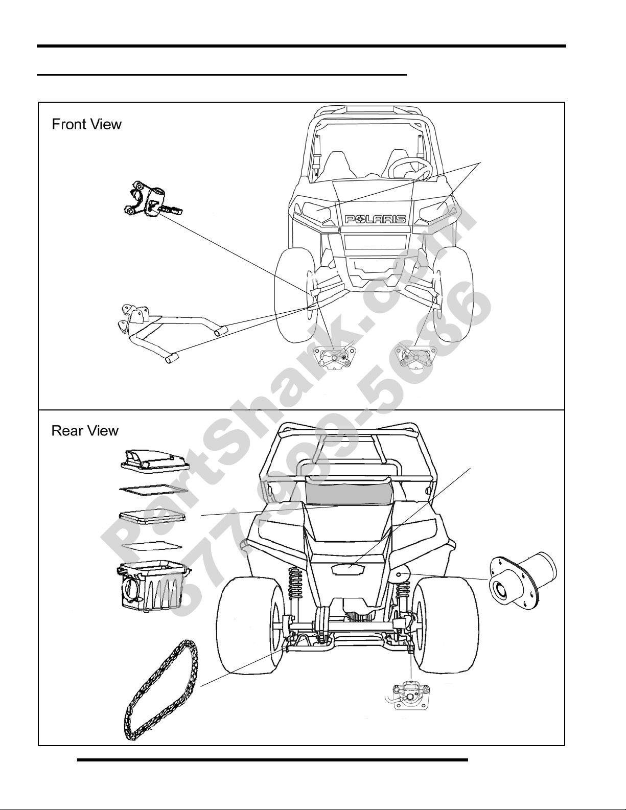
Grease Steering Pivots
Grease A-arm Pivots
Inspect Brake Pads
Inspect / Clean Air Filter
Inspect Brake Pads
Clean / Lubricate Chain
Inspect Exhaust
Daytime Running
Lamps
Trail / Brake Lamp
PartShark.com
877-999-5686
MAINTENANCE REFERENCES / SERVICE LOCATIONS
Front and Rear View
2.6
Page 17
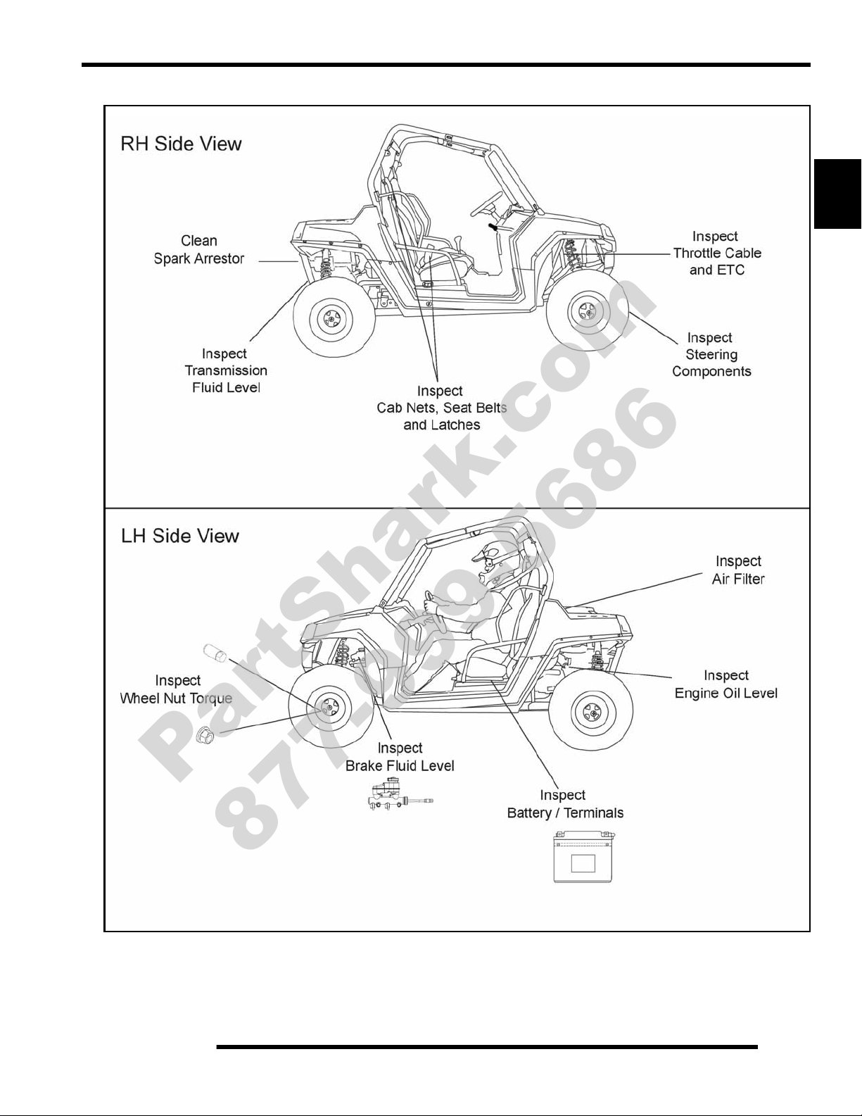
RH and LH Side Views
PartShark.com
877-999-5686
MAINTENANCE
2
2.7
Page 18
MAINTENANCE
PartShark.com
877-999-5686
LUBRICANTS / SERVICE PRODUCTS
Polaris Lubricants, Maintenance and Service Products
Part No. Description
Engine Lubricant
2870791 Fogging Oil (12 oz. Aerosol)
2876248
2872175
2873602
2873603
2873604
2871653
2872276
2871654
2870465 Oil Pump for 1 Gallon Jug
2871312 Grease Gun Kit
2871322
Polaris YOUTH Synthetic 0W-40 4-Cycle
Engine Oil (Quart)
Polaris Semi - Synthetic 20W-40 4-Cycle
Engine Oil (Quart)
Gearcase / Transmission Lubricants
AGL - Synthetic ATV Gearcase Lubricant
(1 Qt.) (12 Count)
AGL - Synthetic ATV Gearcase Lubricant
(1 Gal.) (4 Count)
AGL - Synthetic ATV Gearcase Lubricant
(2.5 Gal.) (2 Count)
ATV Angle Drive Fluid
(8 oz.) (12 Count)
ATV Angle Drive Fluid
(2.5 Gal) (2 Count)
Premium Demand Drive Fluid LT
(1 Qt.) (12 Count)
Grease / Specialized Lubricants
Premium All Season Grease
(3 oz. cartridge) (24 Count)
NOTE: Each item can be purchased separately at
your local Polaris dealer.
Part No. Description
Additives / Sealants / Thread Locking Agent s / Misc.
2870585 Loctite™ Primer N, Aerosol, 25 g
2871956
2871949
2871950
2871951
2870587
2871326
2870652 Fuel Stabilizer (16 oz.) (12 Count)
2871957
2871958
2872189 DOT 4 Brake Fluid (12 Count)
2871557 Crankcase Sealant, 3-Bond 1215 (5oz.)
2872893 Engine Degreaser (12oz.) (12 Count)
NOTE: The number count indicated by each part
number in the table above indicates the number of
units that are shipped with each order.
Loctite™ Thread Sealant 565
(50 ml.) (6 Count)
Loctite™ Threadlock 242
(50 ml.) (10 Count)
Loctite™ Threadlock 242
(6 ml.) (12 Count)
Loctite™ Threadlock 262
(50 ml.) (10 Count)
Loctite™ 518 Gasket Eliminator / Flange
Sealant (50 ml.) (10 Count)
Premium Carbon Clean
(12 oz.) (12 Count)
Black RTV Silicone Sealer
(3 oz. tube) (12 Count)
Black RTV Silicone Sealer
(11 oz. cartridge) (12 Count)
2871423
2871460 Starter Drive Grease (12 Count)
2871329 Dielectric Grease (Nyogel™)
2872348
Premium All Season Grease
(14 oz. cartridge) (10 Count)
Chain Lubricant, Aerosol
(16 oz.) (12 Count)
2.8
Page 19
MAINTENANCE
PartShark.com
877-999-5686
MAINTENANCE REFERENCES
Item Ref. Rec. Lube / Fluid Method Frequency*
Change after 10 hrs, and then
Polaris YOUTH 40W Engine
Engine Oil Page 2.7
Brake Fluid Page 2.7 DOT 4 (PN 2872189)
Transmission Page 2.7
Front A -Arm and
Steering Pivot
Bushings
* More often under severe use, such as operated in water or under severe loads.
**Semi-annually or 50 hours of operation (refer to Maintenance Schedule for additional information)
Page 2.6
Oil or 20-W40 Synthetic.
(Ambient air temperatures
apply- see page 2.19)
AGL Synthetic Gearcase
Lubricant (PN 2873602)
Polaris Premium All Season
Grease (PN 2871423)
Add oil to proper level on
dipstick.
Fill reservoir between MAX
and MIN lines.
Add lube to bottom of fill
plug threads. 24 oz. (710 ml)
Locate grease fittings and
grease with grease gun.
every 50 hours, 6 months or
100 hours thereafter; Change
more often in extremely dirty
conditions, or short trip cold
weather operation.
Fill as required. Change
brake fluid every 2 years.
Change annually***
Semi-annually**
2
***Annually or 100 hours of operation (refer to Maintenance Schedule for additional information)
2.9
Page 20
MAINTENANCE
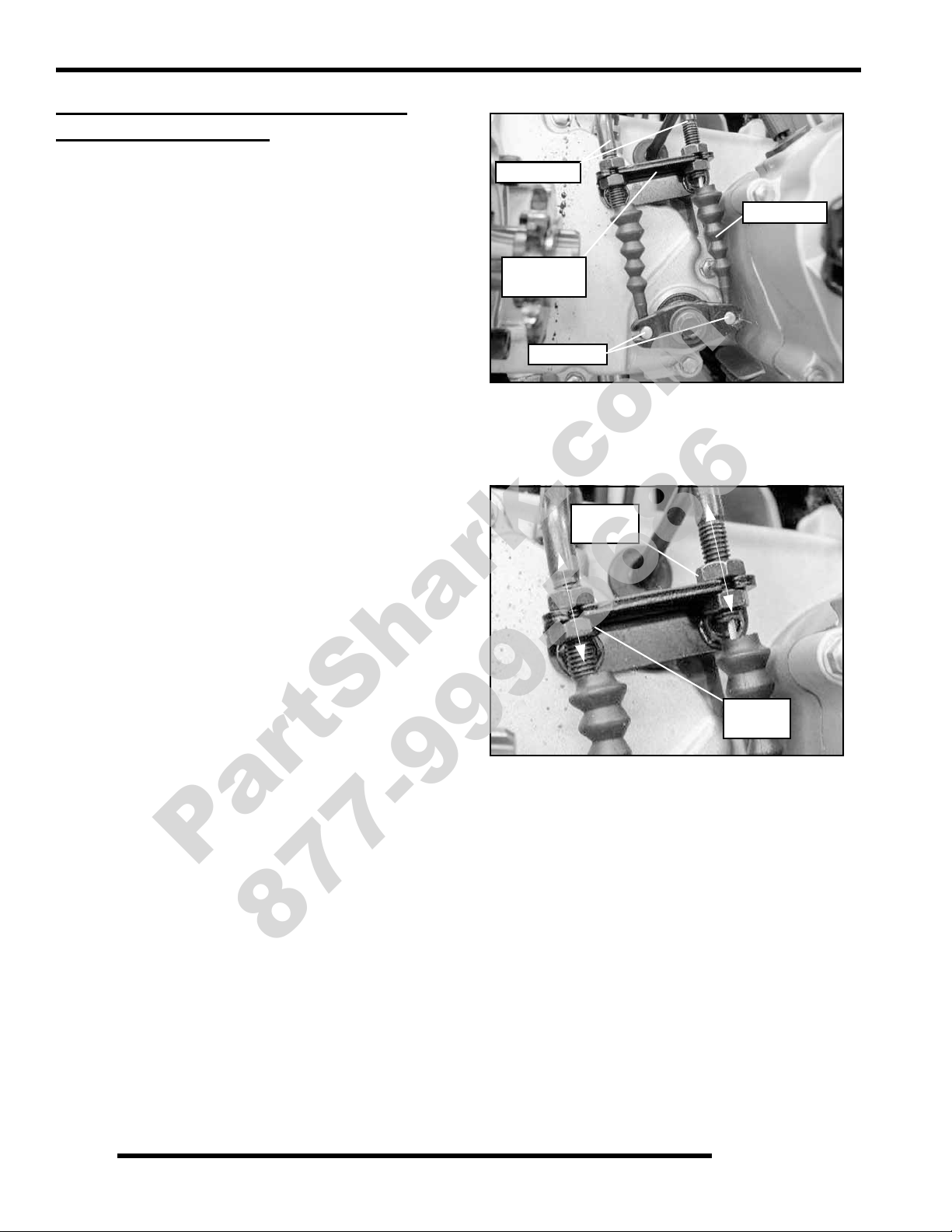
Shift Cable
Mount
Dust Boot
Clevis Pin
Shift Cables
Lower
Jam Nut
Upper
Jam Nut
PartShark.com
877-999-5686
GENERAL VEHICLE INSPECTION AND MAINTENANCE
Pre-Ride / Daily Inspection
Perform the following pre-ride inspection daily, and when
servicing the vehicle at each scheduled maintenance.
• Tires - check condition and pressures
• Fuel tank - fill to proper level
• All brakes - check operation and adjustment
• Throttle - check for free operation and closing
• Running lights/Taillight/Brakelight - also check
operation of all indicator lights and switches
• Ignition switch - check for proper function
• Wheels - check for tightness of wheel nuts and axle
nuts; check to be sure axle nuts are secured by cotter
pins
• Air cleaner element - check for dirt; clean or replace
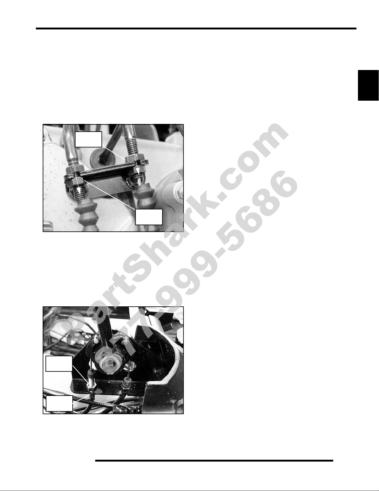
1. Locate the shift cable in the rear wheel well area.
2. Inspect shift cable, clevis pin, pivot bushings, and dust
boot. Replace if worn or damaged.
3. If adjustment is required, loosen the lower jam nut and pull
the cable out of the mount to move the upper jam nut.
Frame, Nuts, Bolts, and Fasteners
Periodically inspect the torque of all fasteners in accordance
with the maintenance schedule. Check that all cotter pins are in
place. Refer to specific fastener torques listed in each chapter.
Shift Cable Inspection / Adjustment
Shift cable adjustment may be necessary if symptoms include:
• Steering - check for free operation noting any unusual
looseness in any area
• Loose parts - visually inspect vehicle for any damaged
or loose nuts, bolts or fasteners
• Check all front and rear suspension components for
wear or damage.
• Ratcheting noise on deceleration
• Inability to engage into a gear
• Excessive gear clash (noise)
• Gear selector moving out of desired range
4. Adjust the shift cables so there is an equal amount of lever
travel when shifting past the Neutral detent into HIGH (H)
and REVERSE (R).
5. Thread the upper jam nuts as required to obtain proper cable
adjustment without binding.
NOTE: This procedure may require a few attempts to
obtain the proper adjustment.
6. Once the proper adjustment is obtained, tighten the lower
jam nut against the mount.
7. Start engine and shift through all gears to ensure the shift
cable is properly adjusted. If transmission still ratchets
after cable adjustment, verify the idle RPM is set correctly,
otherwise the transmission may require service.
2.10
Page 21
MAINTENANCE
Lower
Jam Nut
Upper
Jam Nut
Lower
Jam Nut
Upper
Jam Nut
PartShark.com
877-999-5686
Shift Cable Replacement
Shift cable replacement may be necessary if symptoms include:
• Inability to engage into a gear
• Inability to adjust cables for proper operation
• Gear selector moving out of desired range
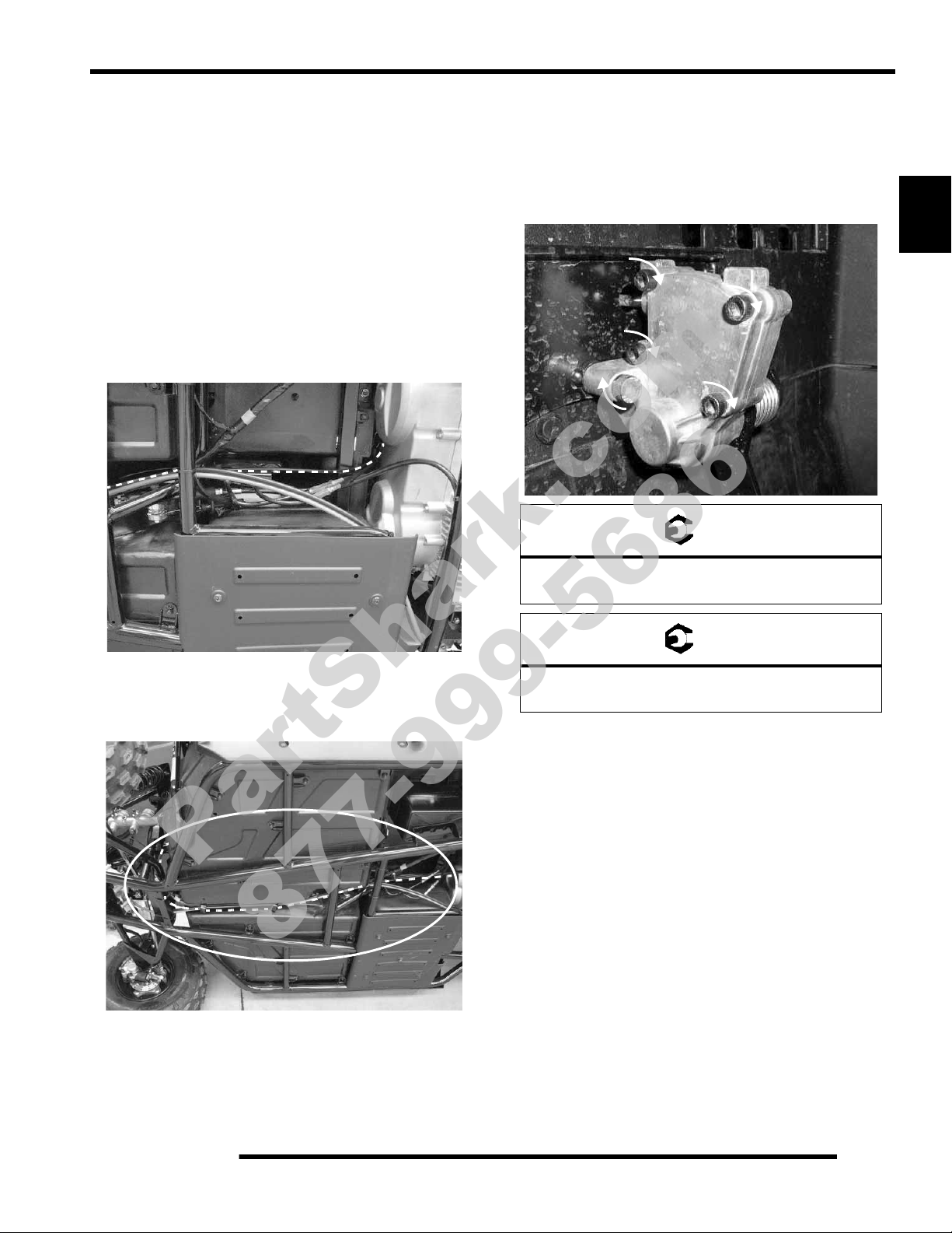
1. Locate the shift cables in the rear wheel well area.
2. Loosen the lower and upper jam nuts and remove the
cables.
8. Raise the vehicle and support it with jackstands in order to
access the underside to remove the cables.
IMPORTANT: Document location of cable ties and
routing prior to removal. This is important for
reassembly.
9. Install new cables and adjust for proper operation and lever
travel without binding.
IMPORTANT: Do not allow cables to hang below
vehicle frame.
10. Once installed, lower the vehicle. Start engine and shift
through all gears to ensure the shift cables are properly
adjusted. If transmission still ratchets after cable
adjustment, verify the idle RPM is set correctly, otherwise
the transmission may require service.
11. Reassemble the console cover, seats and shift knob as
outlined in Chapter 5.
2
3. Inspect shift cable arm. Replace if worn or damaged.
4. Remove the shift knob to prepare for seat panel removal.
Refer to Chapter 5.
5. Refer to Chapter 5 for console cover removal in order to
access the shift cable mount on the lever assembly.
6. Loosen the lower and upper jam nuts and remove the
cables.
7. Inspect shift lever assembly. Replace parts as required if
worn or damaged.
2.11
Page 22
MAINTENANCE
Air Box Access
Secure Clips
PartShark.com
877-999-5686
FUEL SYSTEM AND AIR INTAKE
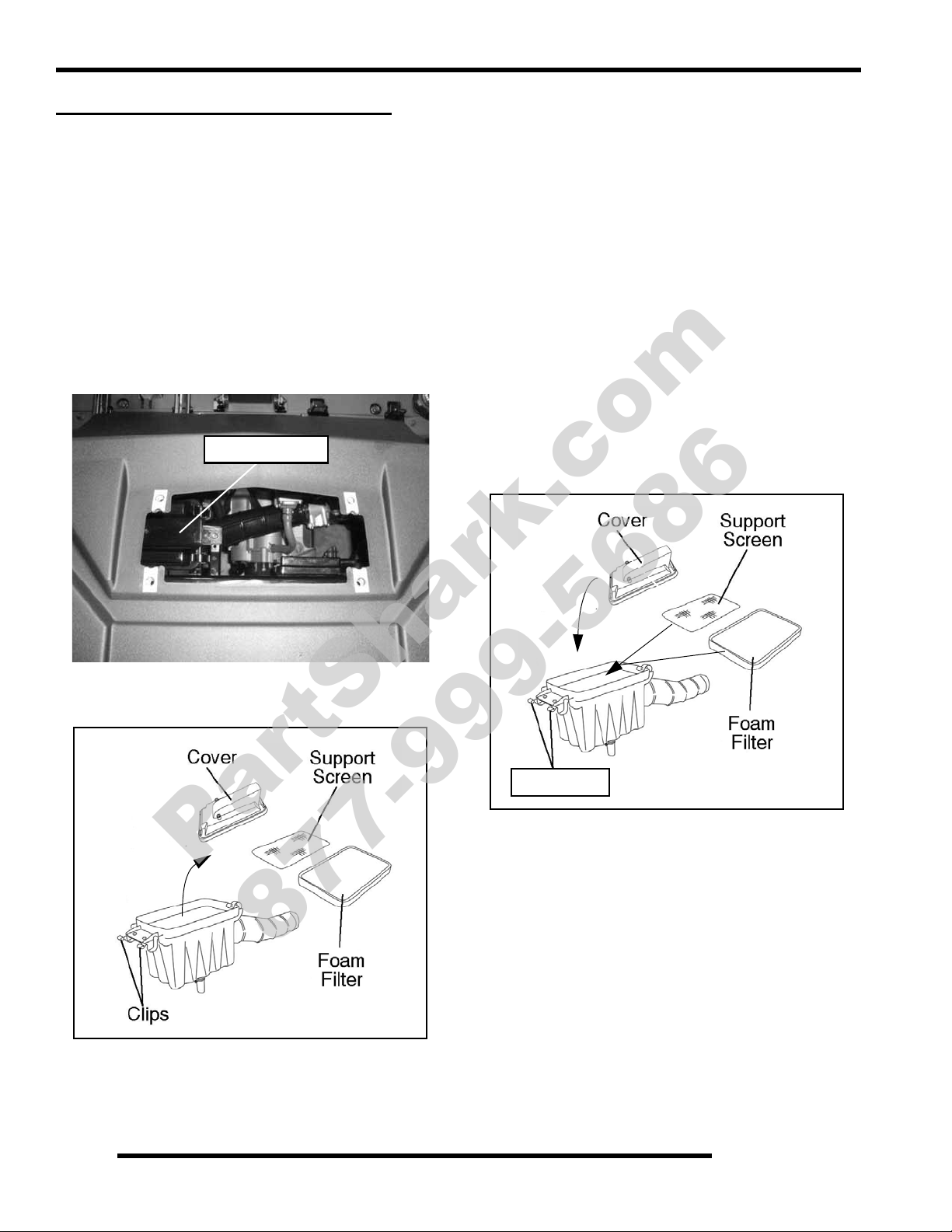
Air Filter Service
It is recommended that the air filter be inspected as part of
pre-ride inspection. If riding in extremely dusty conditions,
apply a small amount of grease to the seal under the air box cap.
In extremely dusty conditions, air filter cleaning will be required
more often.
The filter should be serviced using the following procedure.
Removal
1. The air box is located on the upper frame by the rear LH
wheel. Access the air box by removing the panel located at
the top of the rear cab (under rear basket, if installed).
4. Inspect the air filter element for tears or damage.
NOTE: Filter is washable. Do not discard.
5. Wash the filter in warm soapy water and allow it to air dry.
6. Apply air filter oil (commercially available) to the filter,
following the directions on the label.
NOTE: If unable to clean the filter, replace it.
NOTE: Service the filter more frequently if vehicle is
operated in wet conditions, dusty conditions or at
high throttle openings for extended periods.
Installation
1. Verify the air box and support screen are thoroughly clean.
2. Install a clean, pre-oiled foam filter over the filter support.
NOTE: Apply a small amount of general purpose
grease to the sealing edge of the air box cap seal
before installing.
3. Install air box cap and secure with clips.
2. Unlatch the clips and remove the air box cap. Inspect the
seal. It should adhere tightly to the cover and seal all the
way around.
3. Remove air filter and the filter support screen.
4. Reattach the access panel and tighten the fasteners
sufficiently.
2.12
Page 23
MAINTENANCE
CHOKE CABLE FREEPLA Y
Increase
Decrease
PartShark.com
877-999-5686
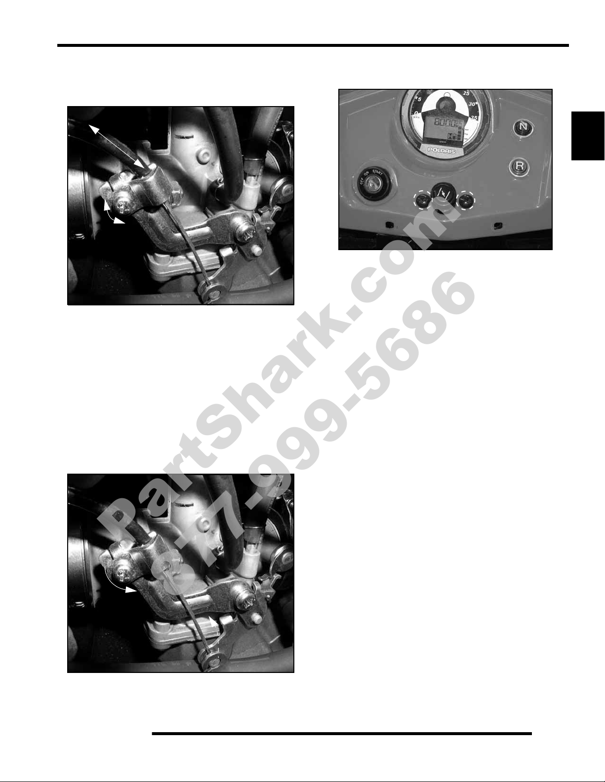
Choke Cable Adjustment
V erify free play of 3/16” (4.76 mm) and smooth operation of the
choke cable at the dash.
Adjustments to the freeplay can be made by loosening the choke
cable bracket at the carburetor and moving the cable in or out to
gain the desired freeplay.
If smooth choke operation is not obtainable, inspect choke cable
for kinks or sharp bends in routing.
Choke Cable Replacement
The choke cable is replaced as an assembly.
1. Engine is off. Place the vehicle in neutral and apply the
parking brake.
2. Remove the cable end from the carburetor.
3. Remove the retaining screws and pull the choke assembly
out at the dash.
2
4. Raise the vehicle and support it with jackstands in order to
access the underside.
IMPORTANT: Document location of cable ties and
routing prior to removal. This is important for
reassembly.
5. Pull the cable out from under the dash and the underside of
the vehicle.
6. Route the new cable from front-to-back, through the
retainers at the bottom of the frame, following the routing
noted during disassembly. Place cable ties at the
appropriate locations.
IMPORTANT: Do not allow cable to hang below
vehicle frame.
7. Reinstall the choke assembly into the dash. Hand-tighten
fasteners sufficiently, using care not to over-tighten.
8. Reinstall the choke cable onto the carburetor.
9. Adjust cable to desired freeplay.
If smooth choke operation is not obtain able, inspect for kinks,
sharp bends in the routing or a linkage obstruction.
2.13
Page 24
MAINTENANCE
Idle Speed
Screw
Increase
Decrease
IDLE SPEED
CAUTION
Increase
Decrease
PILOT AIR
SCREW
PartShark.com
877-999-5686
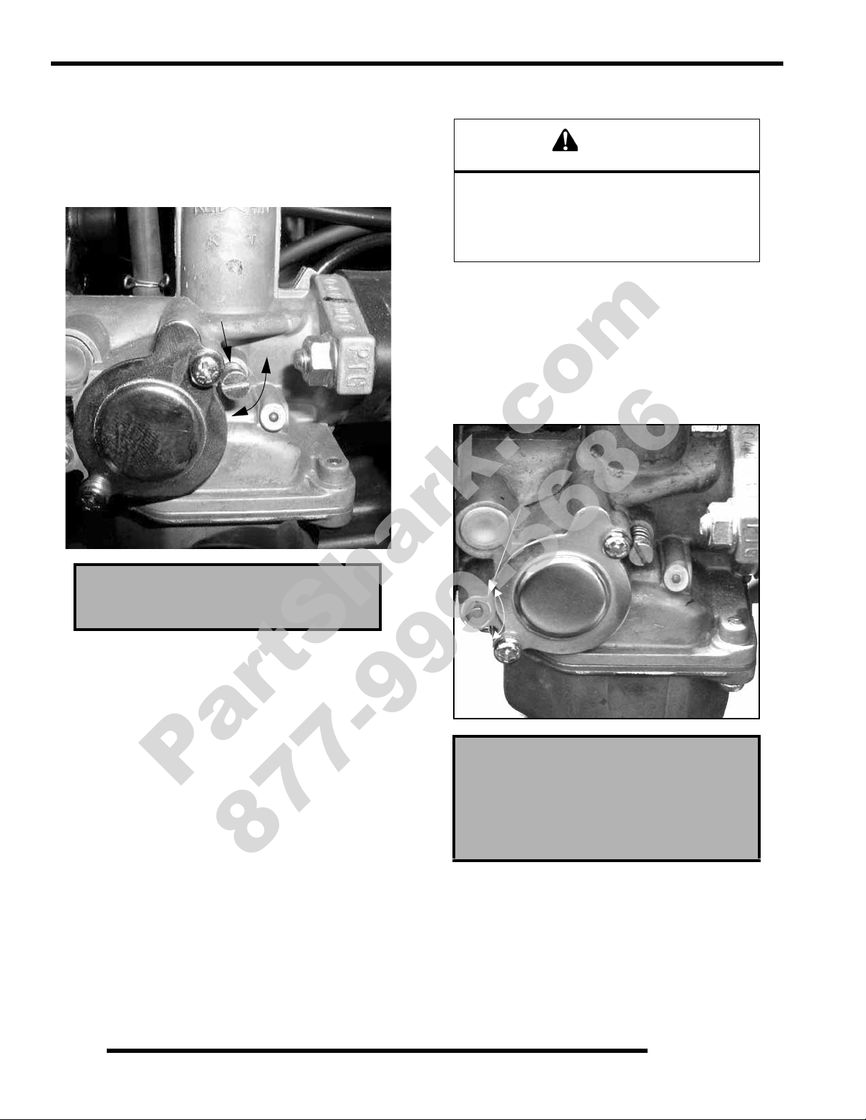
Idle Speed Adjustment
1. Start engine and warm it up thoroughly.
2. Adjust idle speed by turning the slide adjustment screw in
(clockwise) to increase or out (counterclockwise) to
decrease RPM. (Refer to illustration).
Pilot Air Screw Adjustment
The pilot air screw is calibrated at the factory to
meet EPA / CARB regulations for air quality
standards. Cleaning of the pilot circuit must be
performed by a certified repair shop to ensure
air quality standards are not exceeded.
1. Using a portable tachometer, start the engine and verify
the idle speed is set to specification. Always check throttle
cable freeplay after adjusting idle speed and adjust if
necessary.
2. Using ‘D’-shaped screwdriver Special Tool PA-47361
adjust the pilot air screw setting, turn the screw clockwise
until engine idle RPM begins to decrease. Stop turning at
this point and note the screw setting.
Idle Speed
1700 ± 100
NOTE: Always check throttle cable freeplay after
adjusting the idle speed and readjust if necessary.
Pilot Air Screw Base Setting:
2.25 turns out (initial)
Special Tool:
PA-47361
3. Slowly turn mixture screw counterclockwise until idle
speed returns to Idle RPM. Continue turning
counterclockwise until idle RPM begins to drop. Stop
turning at this point and note the screw setting
4. Center the mixture screw between points in Step 2 and 3.
5. Readjust idle speed if not within specification.
2.14
Page 25
MAINTENANCE
WARNING
PartShark.com
877-999-5686
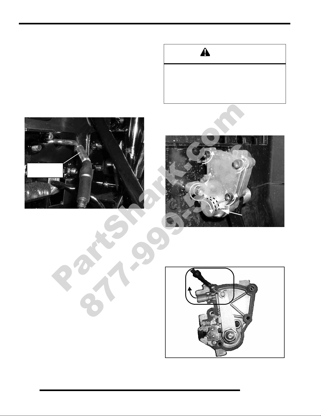
Vent Lines
1. Check fuel tank, crankcase, carburetor and transmission
vent lines for signs of wear, deterioration, damage or
leakage. Replace every two years.
2. Verify vent lines are routed properly and secured with
cable ties.
Fuel System
Gasoline is extremely flammable and explosive
under certain conditions.
Always stop the engine and refuel outdoors or in
a well ventilated area.
Do not smoke or allow open flames or sparks in
or near the area where refueling is performed or
where gasoline is stored.
Do not overfill the tank. Do not fill the tank neck.
If you get gasoline in your eyes or if you swallow
gasoline, seek medical attention immediately.
If you spill gasoline on your skin or clothing,
immediately wash it off with soap and water
and change clothing.
Never start the engine or let it run in an enclosed
area. Engine exhaust fumes are poisonous and
can result loss of consciousness or death
in a short time.
Never drain the fuel when the engine is hot.
Severe burns may result.
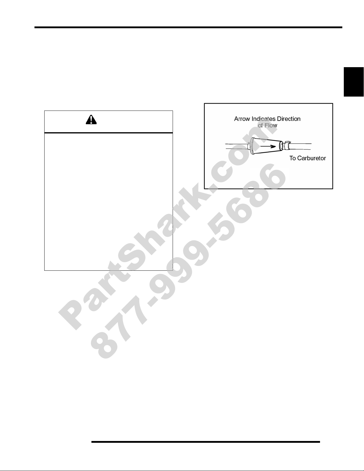
Fuel Filter
The fuel filter should be replaced in accordance with the
“Periodic Maintenance Chart” or whenever sediment is visible
in the filter.
Fuel Filter Location - Located in-line between fuel pump
and carburetor inlet.
To service the fuel filter:
1. Shut off fuel supply at fuel valve.
2. Remove line clamps at both ends of the filter.
3. Remove fuel lines from filter.
4. Install new filter and clamps onto fuel lines.
5. Turn fuel valve to ‘ON’.
6. Start engine and inspect for leaks.
2
2.15
Page 26
MAINTENANCE
Turn knob to operate
the fuel valve
Drain Screw
Open
Close
PartShark.com
877-999-5686
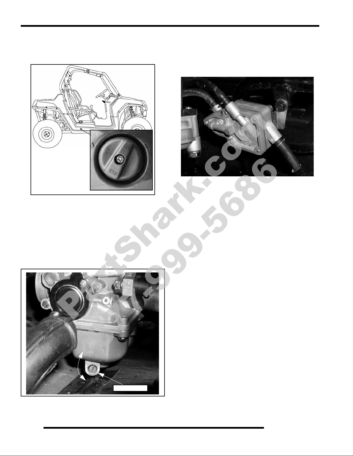
Fuel Valve Location
The fuel valve is located on the passenger side of the vehicle
below the gas cap. Always turn off the fuel when the vehicle is
not in use
Carburetor Draining
The carburetor float bowl should be drained before extended
periods of storage, or periodically to remove accumulated
moisture or sediment from the bowl.
Fuel Pump / Fuel Lines
NOTE: Thoroughly clean the exterior of all fuel
related components before servicing.
The RZR170 fuel pump is located in the right rear wheel well.
1. Check the fuel lines for signs of wear, deterioration,
damage or leakage. Replace if necessary.
2. Be sure fuel line is routed properly.
IMPORTANT: Make sure line is not kinked or pinched.
3. Replace fuel lines every two years.
1. Turn fuel valve to the ‘OFF’ position.
2. Place a container beneath the bowl drain hose.
3. Loosen drain screw and allow fuel in the float bowl and fuel
line to drain completely.
4. Tighten drain screw.
5. Turn fuel valve to “ON” and check for fuel leaks.
6. Start engine and re–check for leaks.
2.16
NOTE: For all other information related to the fuel
System, refer to Chapter 4.
Page 27
MAINTENANCE
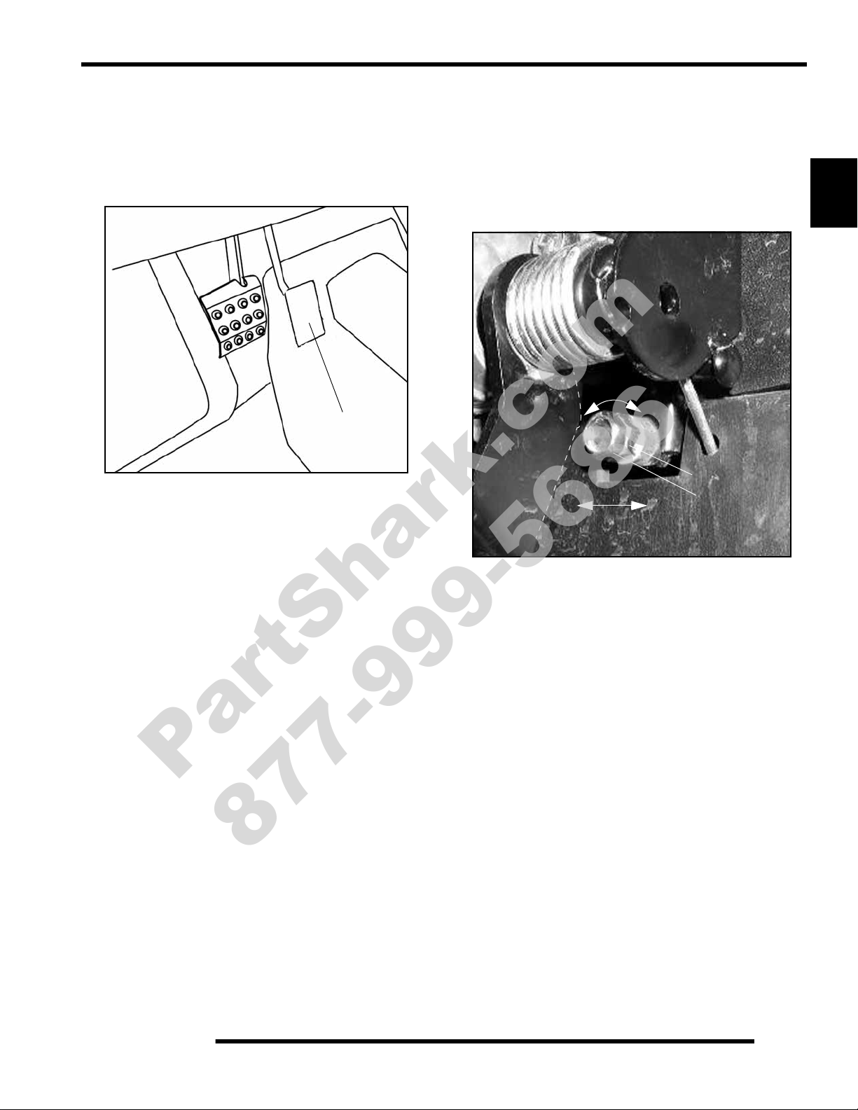
Throttle Pedal
Jam Nut
Stop Screw
Decrease / Increase
SPEED
PartShark.com
877-999-5686
Throttle Pedal Inspection
If the throttle pedal has excessive play due to cable stretch or
cable misadjustment, it will cause a delay in throttle response.
Also, the throttle may not open fully. If the throttle pedal has no
play, the throttle may be hard to control, and the idle speed may
be erratic.
Check the throttle pedal play periodically in accordance with the
Periodic Maintenance Chart and adjust if necessary.
Throttle Stop Speed Control
Use the following procedure to control how far the throttle
opens.
IMPORTANT: This procedure should be performed
by consumers only when they determine that their
child is capable of handling the additional speed.
2
1. Loosen the jam nut.
2. Turn the screw clockwise to increase speed or counter-
clockwise to reduce speed.
3. Tighten the jam nut after adjusting.
2.17
Page 28
MAINTENANCE
Throttle Cable
Adjuster
WARNING
Pivot Bearing
PartShark.com
877-999-5686
Throttle Freeplay Adjustment
Inspection
1. Place the transmission in the Neutral (N) position.
2. Start the engine and warm it up thoroughly.
3. Measure the distance the throttle pedal moves before the
engine begins to pick up speed. Freeplay should be 1/16”
- 1/8” (1.5 - 3 mm).
Adjustment
1. The throttle cable adjuster is located at the throttle pedal
housing, outside of the cab well.
Throttle Cable Replacement
Follow the factory cable routing as installed to
prevent cable pinching, binding or damage.
Do not allow cable to hang below vehicle frame.
Failure to install properly could result in loss of
vehicle control, resulting in severe injury or death.
1. Engine is off. Place the vehicle in neutral and apply the
parking brake.
2. Remove the foot pedal ETC cover screws and ONE leftside housing mounting screw.
2. Slide back the cable adjuster boot.
3. Using an open-end wrench, loosen the adjustment jam nut.
4. Using an open-end wrench, move the cable adjuster until
1/16” to 1/8” (1.5 - 3 mm) of freeplay is achieved at the
throttle pedal.
NOTE: While adjusting, lightly move the throttle
pedal in and out.
5. Re-tighten the jam nut.
6. Apply a small amount of grease to the inside of the boot and
slide it over the cable adjuster to its original position.
NOTE: Pivot bearing inside the housing is a slip-fit
and will require some light prying to separate the
housing. Use caution.
3. Remove the cable from the housing and the ball -end from
the throttle pedal arm.
2.18
Page 29
MAINTENANCE
= T
= T
Pivot Bearing
PartShark.com
877-999-5686
4. Remove the carburetor slide assembly from the carburetor
body and disconnect the throttle cable.
5. Raise the vehicle and support it with jack stands in order to
access the underside of the vehicle.
IMPORTANT: Document location of cable ties and
routing prior to removal. This is important for
reassembly.
6. Remove the panduit straps retaining the throttle cable to the
frame and brake line.
7. Pull the throttle cable out through the back of the vehicle
and discard the cable.
8. Route the new cable from back-to-front, through the
retainers at the bottom of the frame, following the routing
noted during disassembly.
12. Install the new cable onto the carburetor slide assembly and
install the slide into the carburetor. Hand-tighten the slide
cap sufficiently.
13. Place the throttle cable end into the foot pedal housing.
14. Place a new gasket on the housing and install the cover.
Torque the retaining screws to specification.
2
9. Fasten the cable with cable ties at the same locations they
were previously removed.
10. Continue to route the cable towards the front of the vehicle
using the brake line routing as a general guide.
ETC Throttle Housing Screws:
8.5-10 ft. lbs. (11.5-13.5 Nm)
Throttle Pedal Mounting Screws:
16-20 ft. lbs. (21-27 Nm)
15. Start the engine and allow it to warm up.
16. Measure the distance the throttle pedal moves before the
engine begins to pick up speed. Freeplay should be 1/16" 1/8" (1.5 - 3 mm).
• If freeplay is correct, proceed to step 21.
• If adjustment is required, refer to “Throttle Freeplay
Adjustment” procedure.
17. After reassembly and adjustment, field test vehicle to
ensure proper throttle operation.
11. Use cable ties to retain the throttle cable, using the sam e
locations they were previously removed.
NOTE: Be sure to route the throttle cable inside the
retainers.
2.19
Page 30
MAINTENANCE
Dipstick
Full
Add Oil
{
Safe Range
CAUTION
Drain Plug
PartShark.com
877-999-5686
ENGINE
Engine Oil Level
Maintain the oil level within the safe range on the dipstick. Do
not overfill.
To check the oil level:
1. Position the vehicle on a level surface.
2. Remove the dipstick. Wipe it dry with a clean cloth.
Engine Oil Change
1. Position the vehicle on a level surface.
2. Clean area around the drain plug.
3. Run engine until warm.
4. Stop the engine.
Hot oil can cause serious burns to skin. Do not
allow hot oil to come in contact with skin.
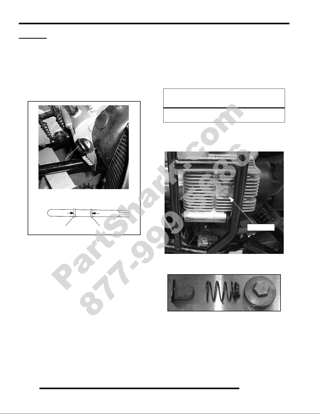
5. Place a drain pan beneath the engine crankcase.
6. Remove the drain plug and pre-filter screen. Allow the oil
to drain completely.
3. Reinstall the dipstick completely.
4. Remove the dipstick and check the oil level.
NOTE: Rising oil level between checks in cool
weather driving, can indicate moisture collecting in
the oil reservoir. If the oil level is over the full mark,
change the oil.
5. Add the recommended oil as needed.
NOTE: Do not fill the over the normal oil operating
range. Filling over the normal operating range could
cause a mist of oil to enter the air box.
6. Reinstall the dipstick.
2.20
7. Wash the oil pre-filter screen with solvent to remove any
debris. Allow the screen to air dry.
8. Inspect the O-ring on drain plug, replace if needed.
NOTE: The sealing surfaces on the drain plug and
crankcase should be clean and free of burrs, nicks
or scratches.
9. Reassemble the pre-filter screen and spring to the pre-filter
plug.
Page 31

MAINTENANCE
= T
PartShark.com
877-999-5686
10. Reinstall the drain plug. Torque to specification.
Crankcase Drain Plug: 18 ft. lbs. (23 Nm)
11. Remove the dipstick. Add recommended oil. Do not
overfill.
Recommended Engine Oil:
Polaris Synthetic Youth 4-Stroke Oil
SAE 40 (Above 32F)
Quart - (PN 2876248)
Gallon - (PN 2876249)
Polaris Semi-Synthetic Oil
20W-40 (Below 32F)
Quart - (PN 2872175)
Gallon - (PN 2872176)
Capacity:
Engine Crankcase Ventilation System Inspection
The engine is equipped with a crankcase ventilation. Follow
the breather hoses from the airbox to the engine and inspect
the hoses for possible kinks or wear . The hoses are form-fitted
for a proper fit.
NOTE: Make sure lines are not kinked or pinched.
2
37 oz. (1.1 ltr)
12. Reinstall the dipstick.
13. Start the engine. Allow it to idle for a short period.
14. Stop the engine and inspect for leaks.
15. Check the oil level. Add oil as needed to bring the level to
the ‘Safe Range’ on the dipstick.
IMPORTANT: Over-filling engine crankcase will result
in oil entering the air box. Maintain the recommen ded
oil level.
Engine/Transmission Mount Locations
Periodically inspect engine/transmission upper and lower
mounts for cracks or damage.
2.21
Page 32

MAINTENANCE
Compression tester adaptor threads
should not exceed spark plug threads.
1/2” (12.07mm)
= In. / mm.
= In. / mm.
PartShark.com
877-999-5686
Compression / Leakdown Test
IMPORTANT: Use of a compression tester adaptor
that is too long WILL CAUSE DAMAGE to the cylinder
head. The adaptor length should be no longer than
the length of the spark plug threads (1/2” or 12.07 mm).
Cylinder Compression
Standard: 130 - 160 psi
Cylinder Leakage
Service Limit: 15%
Inspect if leakage exceeds 15%
Intake Valve Clearance Adjustment
1. Remove the valve cover and secondary air pipe assembly.
2. Verify cam lobes are pointed down.
3. Insert the correct thickness feeler gauge between end of
intake valve stem and adjuster screw.
4. When clearance is correct, hold adjuster screw and tighten
locknut securely.
5. Re-check the valve clearance.
6. Repeat adjustment procedure if necessary until clearance is
correct with locknut secured.
Valve Clearance:
.003” (.07 mm)
Exhaust Valve Clearance Adjustment
1. Remove the valve cover and secondary air pipe assembly.
2. Verify cam lobes are pointed down.
3. Insert the correct thickness feeler gauge between end of
exhaust valve stem and adjuster screw.
4. Loosen locknut and turn adjuster screw until there is a slight
drag on feeler gauge.
5. When clearance is correct, hold adjuster screw and tighten
locknut securely.
6. Re-check the valve clearance.
7. Repeat adjustment procedure if necessary until clearance is
correct with locknut secured.
Valve Clearance:
.003” (.07 mm)
2.22
Page 33

Exhaust - Spark Arrestor
WARNING
= T
Silencer
Retaining
Screws
Arrestor
Screen
PartShark.com
877-999-5686
Do not clean spark arrestor immediately after the
engine has been run, as the exhaust system
becomes very hot. Serious burns could result from
contact with the exhaust components. Allow
components to cool sufficiently before proceeding.
Wear eye protection and gloves.
Never run the engine in an enclosed area. Exhaust
contains poisonous carbon monoxide gas that can
cause loss of consciousness or death in a very
short time.
To remove accumulated carbon, clean the spark arrestor at the
interval recommended in the Periodic Maintenance Chart.
1. Remove the retaining screws and remove the arrestor from
the end of the silencer.
2. Use a non-synthetic brush to clean the arrestor screen. A
synthetic brush may melt if components are warm.
3. Inspect the screen for wear and damage. Replace if
required.
4. Reinstall the arrestor and torque the fasteners to
specification.
MAINTENANCE
2
Spark Arrestor Fasteners
7 ft. lbs. (9.5 Nm)
2.23
Page 34

MAINTENANCE
Transmission Oil Fill/Check
PartShark.com
877-999-5686
TRANSMISSION
Transmission Specification Chart
EARCASE LUBRICANT CAPACITY FILL PLUG TORQUE
G
Transmission
(Main Gearcase)
Transmission Oil Change
NOTE: It is important to foll ow the tra nsmi ssion an d
gearcase maintenance intervals described in the
Periodic Maintenance Chart.
AGL - Synthetic ATV
Gearcase Lubricant
24 oz. (710 ml) 18 ft. lbs. (24 Nm) 30-45 in. lbs. (3-5 Nm)
Transmission Specifications
Specified Lubricant:
AGL Synthetic Gearcase Lubricant
(PN 2873602)
Approximate Capacity at Change:
23.7 oz. (700 ml)
Drain / Level Plug Torque:
30-45 in. lbs. (3-5 Nm)
DRAIN / LEVEL CHECK
LUG TORQUE
P
Transmission Oil Level Check:
The fill plug is located on the side of the gearcase next to the shift
lever bell crank. Maintain the fluid level even with the bottom
of the fill plug hole.
Fill Plug Torque:
18 ft. lbs. (24 Nm)
• Be sure vehicle is positioned on a level surface when
checking or changing fluid.
• Check vent hose to be sure it is routed properly and
unobstructed.
1. Position vehicle on a level surface.
2. Remove the fill plug.
3. Add the recommended fluid through the fill plug hole until
it is at the bottom the check plug hole.
4. Reinstall the check/fill plug and torque to 30-45 in. lbs. (3-
5 Nm) or tighten by hand sufficiently.
2.24
Page 35

MAINTENANCE
= T
Steel Wheel
27 ft. lbs. (37 Nm)
Aluminum Wheel
90 ft. lbs. (122 Nm)
#1
#2
PartShark.com
877-999-5686
Transm ission Oil Change:
1. Remove the level check plug (refer to “Lubricant Level
Check”).
2. Place a drain pan under the main gearcase drain plug.
3. Remove the drain plug and allow to drain completely.
4. Clean the drain plug.
5. Reinstall the drain plug with a new o-ring and torque to
specification.
FINAL DRIVE / WHEEL AND TIRE
Wheel, Hub, and Spindle Torque Table
Item Nut Type Specification
Aluminum Wheels
Steel Wheels
Hub Retaining Nuts
(Front & Rear)
Lug Nut
(#1)
Flange Nut
(#2)
- 40 ft. lbs. (54 Nm)
90 ft. lbs. (122 Nm)
27 ft. lbs. (37 Nm)
2
Transmission Drain Plug Torque:
18 ft. lbs. (24 Nm)
6. Add the recommended fluid through the fill plug hole.
Maintain the fluid level at the bottom of the fill plug hole
when filling. Do not overfill.
7. Reinstall the fill plug.
8. Check for leaks. Discard the used lubricant properly.
NOTE: Do not lubricate the stud or the lug nut.
Wheel Removal
1. Position the vehicle on a level surface.
2. Place the transmission in gear and stop the engine.
3. Loosen the wheel nuts slightly. If wheel hub removal is
required, remove the cotter pin and loosen the hub nut
slightly.
4. Elevate the appropriate side of the vehicle by placing a
suitable jack and stand under the frame.
5. Remove the wheel nuts and remove the wheel.
6. If hub removal is required, remove the hub nut and washers.
Wheel Installation
1. Verify the transmission is in gear.
2. Install the wheel hub, washers, and hub nut, if previously
removed.
3. Place the wheel in the correct position on the wheel hub.
Be sure the valve stem is toward the outside and rotation
arrows on the tire point toward forward rotation.
4. Attach the wheel nuts and finger tighten them.
2.25
Page 36

MAINTENANCE
CAUTION
Wheel Nuts (4)
Hub Nut
Use a new
cotter pin
Note
Tire Rotation
Valve stem
facing outward
Tread
Depth 1/8" (3 mm)
WARNING
CAUTION
PartShark.com
877-999-5686
5. Carefully lower the vehicle to the ground.
6. Torque the wheel nuts and/or hub nut to the proper torque
specification listed in the torque table at the beginning of
this section.
7. If hub nut was removed, install a new cotter pin after the
hub nut has been tightened.
Operating a RANGER 170 with worn tires will
increase the possibility of the vehicle skidding
easily with possible loss of control.
Worn tires can cause an accident.
Always replace tires when the tread depth
measures 1/8", (.3 cm) or less.
Tire Pressure
Maintain proper tire pressure.
Refer to the warning tire pressure decal
applied to the vehicle.
If wheels are improperly installed it could affect
vehicle handling and tire wear. On vehicles with
tapered rear wheel nuts, make sure tapered end
of nut seats properly into taper on wheel.
Tire Inspection
• Improper tire inflation may affect vehicle
maneuverability.
• When replacing a tire always use original equipment
size and type.
• The use of non-standard size or type tires may affect
vehicle handling.
Tire Tread Depth
Always replace tires when tread depth is worn to 1/8" (3 mm) or
less.
Tire Pressure Inspection (Cold)
Front Rear
3 psi (20.7 kPa) 3 psi (20.7 kPa)
Drive Chain Lubrication and Adjustment
Lubricate the drive chain with Polaris chain spray lube or an
approved chain lube at the interval specified in the Periodic
Maintenance Chart. Lubricate more often under severe use, such
as in dirty or wet conditions.
IMPORTANT: Washing the drive chain with a high
pressure washer or solvents can cause premature
wear and chain failure. Do not use a high pressure
washer or gasoline to clean the drive chain. Operating
the vehicle with improper rear drive chain deflection
can result in severe damage to the transmission and
drive components. Always make sure the chain
adjusted within the stated specifications.
1. Check the amount of chain slack by moving the vehicle
slightly forward to gain slack at the top side of the chain.
2. Raise the rear of the vehicle and support securely under the
mainframe. Allow the swing arm to hang at full shock
extension without touching the ground. This establishes the
tightest chain position.
2.26
Page 37

MAINTENANCE
= T
= T
WARNING
PartShark.com
877-999-5686
3. Pull down on the chain tensioner to move it out of the way,
then measure chain deflection. It should have 1/4"-1/2" (612 mm) deflection.
ELECTRICAL AND IGNITION SYSTEM
Battery Maintenance
Keep battery terminals and connections free of corrosion. If
cleaning is necessary, remove the corrosion with a stiff wire
brush. W ash with a solution of one tablespoon baking soda and
one cup water. Rinse well with tap water and dry of f with clean
shop towels. Coat the terminals with dielectric grease or
petroleum jelly.
Battery electrolyte is poisonous. It contains
sulfuric acid. Serious burns can result from
contact with skin, eyes or clothing. Antidote:
External: Flush with water.
Internal: Drink large quantities of water or milk.
Follow with milk of magnesia, beaten egg, or
vegetable oil. Call physician immediately.
Eyes: Flush with water for 15 minutes and get
prompt medical attention.
2
4. Loosen the four rear housing mount bolts (two on each end
of axle).
5. Loosen the chain adjuster locknuts.
6. Turn the chain adjusters evenly to achieve 1/4"-1/2" (6-12
mm) chain deflection.
7. Torque the chain adjuster locknuts. Hold the adjuster stud
securely while tightening the nut to avoid breaking the stud.
Chain Adjuster Locknuts: 18 ft. lbs. (25 Nm)
8. Torque the four rear housing mount bolts.
Rear Housing Mounting Bolts: 43 ft. lbs. (60 Nm)
Batteries produce explosive gases.
Keep sparks, flame, cigarettes, etc. away.
Ventilate when charging or using in an enclosed
space. Always shield eyes when
working near batteries.
KEEP OUT OF REACH OF CHILDREN.
NOTE: Batteries must be fully charged before use or
battery life will be reduced by 10-30% of full
potential. Charge battery for 3-5 hours at a current
equivalent to 1/10 of the battery’s rated amp/hour
capacity. Do not use the vehic le’s stator/alternator
to charge a new battery.
2.27
Page 38

MAINTENANCE
CAUTION
Battery
PartShark.com
877-999-5686
Battery Removal
1. Remove or pull the driver’s seat forward to access the
battery.
2. Disconnect the black (negative) battery cable.
3. Disconnect the red (positive) battery cable.
4. Remove the rubber strap and lift the battery out of the
vehicle.
Battery Off Season Storage
Whenever the vehicle is not used for a period of three months or
more, remove the battery from the vehicle, ensure that it's fully
charged, and store it out of the sun in a cool, dry place. Check
battery voltage each month during storage and recharge as
needed to maintain a full charge.
NOTE: Battery charge can be maintained by using a
Polaris battery tender charger or by charging about
once a month to make up for normal self-discharge.
Battery tenders can be left connected during the
storage period, and will automatically charge the
battery if the voltage drops below a pre-determined
point.
Battery Charging (Maintenance Free)
The sealed battery is already filled with electrolyte and has been
sealed at the factory . Never pry the sealing strip off or add any
type of fluid to this battery.
The single most important thing about maintaining a sealed
battery is to keep it fully charged. Since the battery is sealed and
the sealing strip cannot be removed, you must use a voltmeter or
multimeter to measure the DC voltage at the battery terminals.
To reduce the chance of sparks: Whenever
removing the battery, disconnect the black
(negative) cable first. When reinstalling the
battery, install the black (negative) cable last.
Battery Installation
IMPORTANT: Using a new battery that has not been
fully charged can damage the battery and result in a
shorter life. It can also hinder vehicle performance.
Follow the battery charging procedure before
installing the battery.
1. Ensure the battery is fully charged.
2. Place the battery in the battery holder and secure with
rubber strap.
3. Coat the terminals with dielectric grease or petroleum jelly.
4. Connect and tighten the red (positive) cable first.
5. Connect and tighten the black (negative) cable last.
6. Verify that cables are properly routed and reinstall the
driver’s seat.
1. Check the battery voltage with a voltmeter or multimeter.
The battery voltage should read 12.8 VDC or higher.
2. If the voltage is less than 12.8 volts, charge the bat tery at
1.2 amps or less until battery voltage is 12.8 VDC or
greater.
NOTE: When using an automatic charger, refer to
the charger manufacturer’s instructions for battery
charging directions. When using a constant current
charger, follow the guidelines in the following table:
State of
Charge
100% 12.8 - 13.0 VDC
75% - 100% 12.5 - 12.8 VDC
50% - 75% 12.0 - 12.5 VDC Needs Charge 5 - 11 hrs
25% - 50% 11.5 - 12.0 VDC Needs Charge
0% - 25% 11.5 VDC or l e ss Needs Charge 20 hrs
Voltage Action
None, check
again in 3
months
May need slight
charge, check
again in 3
months
Charge
Time
None
Required
3 - 6 hrs
At least 13
hrs, verify
state of
charge
2.28
Page 39

MAINTENANCE
WARNING
Inspect electrode for
wear or buildup
Gap - .024-.028" (0.6-.07 mm)
Spark Plug Gap
Ground
Terminal Location
PartShark.com
877-999-5686
Spark Plug Service
1. Clean plug area so no dirt or debris can fall into the
cylinder when the plug is removed.
A hot exhaust system and engine can cause serious
burns. Allow engine to cool or wear protective
gloves when removing the spark plug.
2. Remove the spark plug cap.
6. Measure gap with a wire gauge. Refer to specifications in
the following illustration for proper spark plug type and
gap. Adjust gap if necessary by carefully bending the side
electrode.
2
7. If necessary, replace spark plug with proper type.
CAUTION: Severe engine damage may occur if the
incorrect spark plug is used.
8. Apply anti-seize compound to the spark plug threads.
9. Install spark plug and torque to specification.
Recommended Spark Plug:
NGK CR6HSA
Spark Plug Torque:
11 ft. lbs. (15 Nm)
3. Remove spark plug.
4. Inspect electrodes for wear or carbon buildu p. Look fo r a
sharp outer edge on the electrode, with no rounding or
erosion.
5. Clean with electrical contact cleaner or a glass bead spark
plug cleaner only. CAUTION: A wire brush or coated
abrasive should not be used.
Engine To Frame Ground
Inspect engine ground cable connection. Be sure it is clean and
tight. The ground cable runs from the engine starter motor to the
ground terminal location under the driver’s seat.
2.29
Page 40

MAINTENANCE
WARNING
U-Joints
Gearbox
Tie Rod Location
Check for Loose Wheel or Hub
PartShark.com
877-999-5686
STEERING
Steering Inspection
The steering components should be checked periodically for
loose fasteners, worn tie rod ends, ball joints, and damage. Also
check to make sure all cotter pins are in place. If cotter pins are
removed, they must not be re–used. Always use new cotter pins.
Replace any worn or damaged steering components. Steering
should move freely through the entire range of travel without
binding. Check routing of all cables, hoses, and wirin g to be
sure the steering mechanism is not restricted or limited.
NOTE: Whenever steering components are
replaced, check front end alignment.
Due to the critical nature of the procedures outlined in
this chapter, Polaris recommends steering
component repair and adjustment be performed
by an authorized Polaris MSD-certified technician
when replacing worn or damaged steering parts.
Use only genuine Polaris replacement parts.
Steering Inspection / Tie Rod Ends and Hubs
• To check for play in the tie rod end, grasp the steering
tie rod and pull in all directions feeling for movement.
• Elevate front end of machine so front wheels are off the
ground. Check for any looseness in front hub and wheel
assembly by grasping the tire firmly at top and bottom
first, and then at front and rear. Try to move the wheel
and hub by pushing inward and pulling outward.
Steering Wheel Freeplay
Check the steering wheel for specified freeplay and operation.
1. Position the vehicle on level ground.
2. Lightly turn the steering wheel left and right.
3. There should be 0.8”-1.0” (20-25 mm) of freeplay.
4. If there is excessive freeplay or the steering feels rough,
inspect the following components.
• Tie Rod Ends
• Steering Shaft U-Joints
• Steering Gearbox
• If abnormal movement is detected, inspect the hub and
wheel assembly to determine the cause (possible loose
wheel nuts or loose front hub components).
• Refer to Chapter 5 for front hub service procedures.
2.30
Page 41

MAINTENANCE
= In. / mm.
Measurement “B”
Chalk Mark
Measurement “A”
CAUTION
= T
PartShark.com
877-999-5686
Toe Alignment Inspection
1. Place machine on a smooth level surface.
2. Set steering wheel in a straight ahead position and secure
the steering wheel in this position.
3. Place a chalk mark on the center line of the front tires
approximately 10” (25.4 cm) from the floor or as close to
the hub/axle center line as possible.
NOTE: It is important that the height of both marks
be equally positioned in order to get an accurate
measurement.
4. Measure the distance between the marks and record the
measurement. Call this measurement “A”.
Toe Adjustment
If toe alignment is incorrect, measure the distance between
vehicle center and each wheel. This will tell you which tie rod
needs adjusting.
NOTE: Be sure steering wheel is straight ahead
before determining which tie rod(s) need
adjustment.
During tie rod adjustment, it is very important that
the following precautions be taken when
tightening tie rod end jam nuts.
If the rod end is positioned incorrectly it will not
pivot, and may break.
To adjust toe alignment:
• Hold tie rod end to keep it from rotating.
• Loosen jam nuts at both ends of the tie rod.
• Shorten or lengthen the tie rod until alignment is as
required to achieve the proper toe setting as specified in
Toe Alignment Inspection.
• IMPORTANT: When tightening the tie rod end jam
nuts, the rod ends must be held parallel to prevent rod
end damage and premature wear. Damage may not be
immediately apparent if done incorrectly.
2
5. Rotate the tires 180
backward. Position chalk marks facing rearward, even with
the hub/axle center line.
6. Again measure the distance between the marks and record.
Call this measurement “B”. Subtract measurement “B”
from measurement “A”. The difference between
measurements “A” and “B” is the vehicle toe alignment.
The recommended vehicle toe tolerance is 1/8” to 1/4”
(.3 to .6 cm) toe out. This means the measurement at the
front of the tire (A) is 1/8” to 1/4” (.3 to .6 cm) wider than
the measurement at the rear (B).
(A) - (B) = 1/8 - 1/4" (.3 to .6 cm)
by moving vehicle forward or
Wheel Toe-Out:
• After alignment is complete, torque jam nuts to
specification. Keep tie rod parallel to the mounting
surface.
Tie Rod Jam Nut Torque:
12-14 ft. lbs. (16-19 Nm)
2.31
Page 42

MAINTENANCE
WARNING
Increase
Preload
Decrease
Preload
PartShark.com
877-999-5686
SUSPENSION
Spring Preload Adjustment
The front and rear shock absorber springs are adjustable by
rotating the adjustment cam to change spring tension preload.
Uneven adjustment may cause poor handling of the
vehicle, which could result in an accident and
serious injury or death. Always adjust all spring
preloads equally.
Suspension Spring Adjustment
1. Position the vehicle on a level surface and stop the engine.
2. Raise and safely support the front or rear of the vehicle off
the ground to allow the suspension to fully extend.
NOTE: The tires should not be touching the ground.
3. To adjust the shock spring preload, rotate the adjustment
cam clockwise to increase spring tension or counterclockwise to decrease spring tension using the supplied
spanner wrench.
BRAKE SYSTEM
Brake Fluid Inspection
Always check the brake pedal travel and inspect the brake fluid
reservoir level before each operation. If the fluid level is low,
add DOT 4 brake fluid only.
Brake fluid should be changed every two years. The fluid
should also be changed anytime the fluid becomes
contaminated, the fluid level is below the minimum level, or if
the type and brand of the fluid in the reservoir is unknown.
The brake fluid master cylinder reservoir can be accessed
through the left front wheel well.
1. Position the vehicle on a level surface. Engine off.
2. Place the transmission in gear and lock the parking brake.
3. View the brake fluid level in the reservoir. The level should
be between the MAX and MIN level lines.
4. If the fluid level is lower than the MIN level line, add brake
fluid until it reaches the MAX level line.
5. Install the reservoir cap and apply the brake pedal
forcefully for a few seconds, then check for fluid leaks
around the master cylinder and brake caliper fittings.
Special Tool:
Shock Spanner Wrench
4. Each notch of the adjustment will add 6% - 8% more
preload to the spring over the primary position.
2.32
Page 43

Brake Pad / Disc Inspection
Measure Pad Material
Service Limit:
.040" (1 mm)
Thickness
Measure Brake Disc Thickness
Service Limit:
.170" (4.32 mm)
Front
Disc
Rear
Disc
PartShark.com
877-999-5686
1. Check the brake pads for wear, damage, or looseness.
2. Inspect the brake pad wear surface for excessive wear.
3. Pads should be changed when the friction material is worn
to .040” (1 mm).
4. Check surface condition of the brake discs.
MAINTENANCE
2
5. Measure the thickness of the front and rear brake discs.
6. The disc(s) should be replaced if thickness is less than .170”
(4.32 mm).
Brake Hose and Fitting Inspection
Check brake system hoses and fittings for cracks, deterioration,
abrasion, and leaks. Tighten any loose fittings and replace any
worn or damaged parts.
2.33
Page 44

MAINTENANCE
PartShark.com
877-999-5686
MAINTENANCE LOG
Service Date Hours / Miles (km) Service Performed / Comments Dealer / Technician
2.34
Page 45

ENGINE
PartShark.com
877-999-5686
CHAPTER 3
ENGINE
TOOLS. . . . . . . . . . . . . . . . . . . . . . . . . . . . . . . . . . . . . . . . . . . . . . . . . . . . . . . . . . . . . . . . 3.3
SPECIAL TOOLS . . . . . . . . . . . . . . . . . . . . . . . . . . . . . . . . . . . . . . . . . . . . . . . . . . . . . . .3.3
TORQUE SPECIFICATIONS. . . . . . . . . . . . . . . . . . . . . . . . . . . . . . . . . . . . . . . . . . . . . . . 3.3
ENGINE TORQUE SPECIFICATIONS. . . . . . . . . . . . . . . . . . . . . . . . . . . . . . . . . . . . . . .3.3
TORQUE PATTERNS . . . . . . . . . . . . . . . . . . . . . . . . . . . . . . . . . . . . . . . . . . . . . . . . . . .3.3
ENGINE INFORMATION. . . . . . . . . . . . . . . . . . . . . . . . . . . . . . . . . . . . . . . . . . . . . . . . . . 3.4
ENGINE EXPLODED VIEWS. . . . . . . . . . . . . . . . . . . . . . . . . . . . . . . . . . . . . . . . . . . . . .3.4
ENGINE LUBRICATION. . . . . . . . . . . . . . . . . . . . . . . . . . . . . . . . . . . . . . . . . . . . . . . . . .3.5
PISTON IDENTIFICATION . . . . . . . . . . . . . . . . . . . . . . . . . . . . . . . . . . . . . . . . . . . . . . . .3.5
ACCESSIBLE COMPONENTS. . . . . . . . . . . . . . . . . . . . . . . . . . . . . . . . . . . . . . . . . . . . .3.5
ENGINE SERVICE DATA. . . . . . . . . . . . . . . . . . . . . . . . . . . . . . . . . . . . . . . . . . . . . . . . .3.6
ENGINE SERVICE DATA. . . . . . . . . . . . . . . . . . . . . . . . . . . . . . . . . . . . . . . . . . . . . . . . .3.7
OIL FLOW DIAGRAM. . . . . . . . . . . . . . . . . . . . . . . . . . . . . . . . . . . . . . . . . . . . . . . . . . . .3.8
ENGINE SYSTEMS SERVICE . . . . . . . . . . . . . . . . . . . . . . . . . . . . . . . . . . . . . . . . . . . . . 3.9
BREATHER / OIL SEPARATOR . . . . . . . . . . . . . . . . . . . . . . . . . . . . . . . . . . . . . . . . . . .3.9
EMISSIONS SECONDARY AIR SYSTEM . . . . . . . . . . . . . . . . . . . . . . . . . . . . . . . . . . .3.10
COOLING SHROUD REMOVAL/INSTALLATION . . . . . . . . . . . . . . . . . . . . . . . . . . . . .3.11
ENGINE REMOVAL . . . . . . . . . . . . . . . . . . . . . . . . . . . . . . . . . . . . . . . . . . . . . . . . . . . .3.12
ENGINE INSTALLATION NOTES . . . . . . . . . . . . . . . . . . . . . . . . . . . . . . . . . . . . . . . . .3.12
TOP-END DISASSEMBLY . . . . . . . . . . . . . . . . . . . . . . . . . . . . . . . . . . . . . . . . . . . . . . . 3.13
ENGINE REMOVAL/INSTALLATION. . . . . . . . . . . . . . . . . . . . . . . . . . . . . . . . . . . . . . .3.13
FINDING TOP DEAD CENTER (TDC). . . . . . . . . . . . . . . . . . . . . . . . . . . . . . . . . . . . . .3.13
CAM CHAIN TENSIONER INSPECTION. . . . . . . . . . . . . . . . . . . . . . . . . . . . . . . . . . . .3.13
ROCKER ASSEMBLY
DISASSEMBLY AND INSPECTION. . . . . . . . . . . . . . . . . . . . . . . . . . . . . . . . . . . . . . . .3.14
CAMSHAFT REMOVAL . . . . . . . . . . . . . . . . . . . . . . . . . . . . . . . . . . . . . . . . . . . . . . . . .3.15
CAMSHAFT INSPECTION. . . . . . . . . . . . . . . . . . . . . . . . . . . . . . . . . . . . . . . . . . . . . . .3.15
CYLINDER HEAD REMOVAL . . . . . . . . . . . . . . . . . . . . . . . . . . . . . . . . . . . . . . . . . . . .3.16
CYLINDER HEAD INSPECTION . . . . . . . . . . . . . . . . . . . . . . . . . . . . . . . . . . . . . . . . . .3.17
CYLINDER HEAD WARP INSPECTION . . . . . . . . . . . . . . . . . . . . . . . . . . . . . . . . . . . .3.17
COMBUSTION CHAMBER INSPECTION . . . . . . . . . . . . . . . . . . . . . . . . . . . . . . . . . . .3.17
CYLINDER HEAD DISASSEMBLY . . . . . . . . . . . . . . . . . . . . . . . . . . . . . . . . . . . . . . . .3.17
VALVE INSPECTION. . . . . . . . . . . . . . . . . . . . . . . . . . . . . . . . . . . . . . . . . . . . . . . . . . .3.18
VALVE SEAT RECONDITIONING . . . . . . . . . . . . . . . . . . . . . . . . . . . . . . . . . . . . . . . . .3.19
CYLINDER HEAD ASSEMBLY . . . . . . . . . . . . . . . . . . . . . . . . . . . . . . . . . . . . . . . . . . .3.21
VALVE SEALING TEST . . . . . . . . . . . . . . . . . . . . . . . . . . . . . . . . . . . . . . . . . . . . . . . . .3.22
CYLINDER REMOVAL. . . . . . . . . . . . . . . . . . . . . . . . . . . . . . . . . . . . . . . . . . . . . . . . . .3.22
CAM CHAIN FOLLOWER / TENSIONER GUIDE REMOVAL . . . . . . . . . . . . . . . . . . . .3.22
PISTON REMOVAL . . . . . . . . . . . . . . . . . . . . . . . . . . . . . . . . . . . . . . . . . . . . . . . . . . . .3.23
CYLINDER INSPECTION. . . . . . . . . . . . . . . . . . . . . . . . . . . . . . . . . . . . . . . . . . . . . . . .3.23
CYLINDER HONE SELECTION / HONING PROCEDURE . . . . . . . . . . . . . . . . . . . . . .3.24
HONING TO DEGLAZE . . . . . . . . . . . . . . . . . . . . . . . . . . . . . . . . . . . . . . . . . . . . . . . . .3.24
PISTON INSPECTION . . . . . . . . . . . . . . . . . . . . . . . . . . . . . . . . . . . . . . . . . . . . . . . . . .3.24
PISTON RING INSTALLED GAP. . . . . . . . . . . . . . . . . . . . . . . . . . . . . . . . . . . . . . . . . .3.25
3
3.1
Page 46

ENGINE
PartShark.com
877-999-5686
BOTTOM-END DISASSEMBLY . . . . . . . . . . . . . . . . . . . . . . . . . . . . . . . . . . . . . . . . . . . 3.26
STARTER DRIVE GEAR REMOVAL AND INSPECTION . . . . . . . . . . . . . . . . . . . . . . .3.26
FLYWHEEL REMOVAL / INSPECTION. . . . . . . . . . . . . . . . . . . . . . . . . . . . . . . . . . . . . 3.27
CRANKSHAFT ONE WAY GEAR / DRIVE SPROCKET
REMOVAL AND INSPECTION. . . . . . . . . . . . . . . . . . . . . . . . . . . . . . . . . . . . . . . . . . . .3.28
STARTER DRIVE ONE-WAY CLUTCH
REMOVAL AND INSPECTION. . . . . . . . . . . . . . . . . . . . . . . . . . . . . . . . . . . . . . . . . . . .3.29
BALANCE SHAFT SPROCKET
REMOVAL AND INSPECTION. . . . . . . . . . . . . . . . . . . . . . . . . . . . . . . . . . . . . . . . . . . .3.29
OIL PUMP REMOVAL / DRIVE CHAIN INSPECTION. . . . . . . . . . . . . . . . . . . . . . . . . .3.30
CRANKCASE DISASSEMBLY . . . . . . . . . . . . . . . . . . . . . . . . . . . . . . . . . . . . . . . . . . . . 3.32
CRANKCASE SEPARATION AND
CAM CHAIN REMOVAL. . . . . . . . . . . . . . . . . . . . . . . . . . . . . . . . . . . . . . . . . . . . . . . . . 3.32
CRANKSHAFT REMOVAL. . . . . . . . . . . . . . . . . . . . . . . . . . . . . . . . . . . . . . . . . . . . . . . 3.32
CRANKSHAFT / CAM CHAIN / SPROCKET INSPECTION . . . . . . . . . . . . . . . . . . . . . 3.33
CRANKCASE / BEARING INSPECTION. . . . . . . . . . . . . . . . . . . . . . . . . . . . . . . . . . . . 3.33
CRANKCASE OIL STRAINER INSPECTION . . . . . . . . . . . . . . . . . . . . . . . . . . . . . . . .3.33
ENGINE REASSEMBLY . . . . . . . . . . . . . . . . . . . . . . . . . . . . . . . . . . . . . . . . . . . . . . . . . 3.34
BEARING / SEAL INSTALLATION. . . . . . . . . . . . . . . . . . . . . . . . . . . . . . . . . . . . . . . . . 3.34
CRANKCASE REASSEMBLY . . . . . . . . . . . . . . . . . . . . . . . . . . . . . . . . . . . . . . . . . . . . 3.34
CHAIN GUIDE/TENSIONER INSTALLATION . . . . . . . . . . . . . . . . . . . . . . . . . . . . . . . . 3.35
CRANKSHAFT, BALANCE SHAFT AND STARTER DRIVE GEAR INSTALLATION . . 3.35
OIL PUMP AND CHAIN INSTALLATION. . . . . . . . . . . . . . . . . . . . . . . . . . . . . . . . . . . .3.36
PISTON RING INSTALLATION . . . . . . . . . . . . . . . . . . . . . . . . . . . . . . . . . . . . . . . . . . . 3.37
PISTON INSTALLATION . . . . . . . . . . . . . . . . . . . . . . . . . . . . . . . . . . . . . . . . . . . . . . . . 3.38
CYLINDER INSTALLATION. . . . . . . . . . . . . . . . . . . . . . . . . . . . . . . . . . . . . . . . . . . . . . 3.39
CYLINDER HEAD AND CAMSHAFT INSTALLATION. . . . . . . . . . . . . . . . . . . . . . . . . .3.39
CAMSHAFT TIMING . . . . . . . . . . . . . . . . . . . . . . . . . . . . . . . . . . . . . . . . . . . . . . . . . . .3.40
ROCKER ARM / SHAFT ASSEMBLY . . . . . . . . . . . . . . . . . . . . . . . . . . . . . . . . . . . . . .3.44
ROCKER ASSEMBLY INSTALLATION . . . . . . . . . . . . . . . . . . . . . . . . . . . . . . . . . . . . .3.44
CAM CHAIN TENSIONER INSTALLATION. . . . . . . . . . . . . . . . . . . . . . . . . . . . . . . . . .3.45
INTAKE VALVE CLEARANCE ADJUSTMENT . . . . . . . . . . . . . . . . . . . . . . . . . . . . . . . 3.45
EXHAUST VALVE CLEARANCE ADJUSTMENT . . . . . . . . . . . . . . . . . . . . . . . . . . . . .3.45
STARTER DRIVE ASSEMBLY. . . . . . . . . . . . . . . . . . . . . . . . . . . . . . . . . . . . . . . . . . . . 3.46
FLYWHEEL INSTALLATION . . . . . . . . . . . . . . . . . . . . . . . . . . . . . . . . . . . . . . . . . . . . . 3.46
STATOR INSTALLATION. . . . . . . . . . . . . . . . . . . . . . . . . . . . . . . . . . . . . . . . . . . . . . . . 3.46
STATOR HOUSING INSTALLATION. . . . . . . . . . . . . . . . . . . . . . . . . . . . . . . . . . . . . . . 3.47
EXHAUST SYSTEM. . . . . . . . . . . . . . . . . . . . . . . . . . . . . . . . . . . . . . . . . . . . . . . . . . . . 3.48
TROUBLESHOOTING. . . . . . . . . . . . . . . . . . . . . . . . . . . . . . . . . . . . . . . . . . . . . . . . . . . 3.49
SPARK PLUG FOULING . . . . . . . . . . . . . . . . . . . . . . . . . . . . . . . . . . . . . . . . . . . . . . . .3.49
GENERAL TROUBLESHOOTING . . . . . . . . . . . . . . . . . . . . . . . . . . . . . . . . . . . . . . . . . 3.49
3.2
Page 47

ENGINE
2
4
5
6
1
6 mm
Cylinder Base / Head and
Rocker Assembly
3
2
RH Crankcase - (Inside Stator Cover)
1
1
2
3
4
5
6
7
8
9
RH Crankcase - Stator Cover
PartShark.com
877-999-5686
TOOLS
Special Tools
PART NUMBER TOOL DESCRIPTION
2870390 Piston Support Block
PA-45153 Flywheel Puller
PA-49959
PA-47344
PA-49335
PA-49336
Transmission Output
Shaft Collar Tool
Balance Shaft Slotted
Nut Socket
Crankshaft Slotted Nut
Socket
Flywheel Puller Adaptor
(Use with PA-45153)
TORQUE SPECIFICATIONS
Engine Torque Specifications
TORQUE SPECIFICATIONS
Fastener
Camshaft Chain Guide
Pivot Bolt
Camshaft Chain
Tensioner
Camshaft Chain
Tensioner Cap
Carburetor Intake 6mm 7-8 (9-11 Nm)
Cylinder/Head Nuts 10mm 18 (25 Nm)
Cylinder Base Screws 6mm 5-7 (7-9 Nm)
Crankcase (inner) 6mm 14-15 (19-21 Nm)
Thread
Size
6mm 5-7 (7-9 Nm)
6mm 5-7 (7-9 Nm)
6mm 5-7 (7-9 Nm)
ES35C
Ft. Lbs. (Nm)
Oil Pump Sprocket Nut 6mm 7-8 (9-11 Nm)
Oil pump baffle plate 6mm 4-5 (5-7 Nm)
Stator Assembly 6mm 7-8 (9-11 Nm)
Stator Housing 6mm 7-8 (9 -11 Nm)
Valve Cover 6mm 7-8 (9-11 Nm)
V alve Adjuster Lock Nut 5mm 4-5 (5-7 Nm)
Starter Motor 6mm 5-7 (7-9 Nm)
Spark Plug 12mm 11 (15 Nm)
Pulse Coil Screws 5mm 4-5 (5-7 Nm)
Torque Patterns
Tighten cylinder head, cylinder base, and crankcase fasteners in
3 steps following the sequence outlined. Refer to the table for
torque specifications.
3
Crankshaft Slotted Nut 14mm 43 (58 Nm)
Balancer Shaft Slotted
Nut
Exhaust Nuts 6mm 7-8 (9-11 Nm)
Flywheel Nut 14mm 43 (58 Nm)
Cooling Fan 6mm 4-5 (5-7 Nm)
Oil Drain Bolt
(Crankcase)
Oil Pump
Screws
14mm 43 (58 Nm)
14mm 18 (25 Nm)
6mm 4-5 (5-7 Nm)
3.3
Page 48

ENGINE
Crankshaft
Cylinder /
and Piston
Cylinder Head
Crankcase
Valve Train
PartShark.com
877-999-5686
ENGINE INFORMATION
Engine Exploded Views
3.4
Page 49

ENGINE
PartShark.com
877-999-5686
Engine Lubrication
Oil Type:**
Above 32F
Polaris Youth 4-Stroke Oil (40 W)
Quart - (PN 2876248)
Gallon - (PN2876249)
Below 32F
Polaris Semi-Synthetic Engine Oil (20W-40)
Quart - (PN 2872175)
Gallon - (PN2872176)
Capacity: Approximately 37 oz. (1.1 ltr.)
Drain Plug (Engine Oil): 18 ft. lbs. (23 Nm)
Screen Fitting: 11 ft. lbs. (15 Nm)
Oil Pressure Specification: Not Applicable
** For break-in period after engine top end service, use an SAE
40W mineral based oil to ensure complete piston ring seating to
cylinder wall. Change to above recommendation after 10 hours.
Piston Identification
The piston may have or may not have an identification mark for
piston placement. If the piston has an identification mark, follow
the directions for piston placement below. If the piston does not
have an identification mark, the direction for placement of the
piston does not matter.
Accessible Components
The following components can be serviced or removed with the
engine installed in the frame:
• Flywheel
• Alternator/Stator
• Starter Motor/Starter Drive
• Oil pump / Chain
• Rocker Arms
• Carburetor
• Transmission Components
• Val ves
• Cylinder Head
• Cylinder
• Piston/Rings
• Camshaft
The following components require engine removal for service:
• Cam Chain and Sprockets
• Crankshaft
• Crankshaft Main Bearings
• Crankcase/Bearings
3
Note the directional and identification marks when viewing the
pistons from the top. The letters “IN” must always be toward the
intake side of the engine. The other numbers are used for
identification as to diameter, length and design. Four stroke
engine rings are rectangular profile. Any numbers or letters on
the rings (except oil control rings) must be positioned upward.
See text for oil control ring upper rail installation.
Engine Model
No.
ES35C N/A
Oversize
Available (mm)
Standard Piston
Identification
”IN” marking on
top of piston
toward intake
• Balancer/Bearings
NOTE: Cam chain service requires crankshaft
removal, as the chain is located on the pto side of
the engine.
NOTE: Crankshaft components are not serviceable.
Replace crankshaft as an assembly.
3.5
Page 50

ENGINE
PartShark.com
877-999-5686
Engine Service Data
Cylinder Head / Valvetrain ES35C
Rocker Arm/Shaft
Camshaft Cam lobe height
Cylinder Head Surface warpage limit .002” (.05 mm)
Valve Clearance
Valve Seat Angle Contacting width
Valve Stem diameter
Valve Guide Inner Diameter
Valve Spring
Rocker arm ID .3936 - .4007" (10.00 - 10.18 mm)
Rocker shaft OD .3925 - .3931" (9.972 - 9.987 mm)
In
Ex
In Std .003" (.07 mm)
Ex Std .003" (.07 mm)
In
Ex
Free Length
Squareness
Std 1.1730" (29.795 mm)
Limit 1.1574" (29.40 mm)
Std 1.1637" (29.56 mm)
Limit 1.1480" (29.16 mm)
Std . 039" (1.0 mm)
Limit .063" (1.6 mm)
Std . 039" (1.0 mm)
Limit .063" (1.6 mm)
In .1958 - .1960" (4.975 - 4.980 mm)
Ex .1950 - .1956" (4.955 - 4.970 mm)
Limit .1921" (4.9 mm)
In .1968 - .1973" (5.0 - 5.012 mm)
Ex .1968 - .1973" (5.0 - 5.012 mm)
Limit .1980" (5.03 mm)
Inner 1.275" (32.4 mm)
Outer 1.385" (35.2 mm)
0.075” (1.9 mm)
Cam Chain Install new as a part of any crankshaft removal
KEY - Std: Standard; OS: Oversize; ID: Inner Diameter; OD: Outer Diameter; Mag: Magneto Side;
PTO: Power Take Off
3.6
Page 51

Engine Service Data
PartShark.com
877-999-5686
Cylinder / Piston / Connecting Rod ES35C
Surface warpage limit (mating with cylinder head) .002” (0.05 mm)
Cylinder bore Std 2.4015 - 2.4019" (61 - 61.01 mm)
Taper limit .002” (0.05 mm)
Cylinder
Piston
Piston Pin
Out of round limit .002” (0.05 mm)
Piston to cylinder clearance
Boring Limit Not Applicable
Outer diameter
Pin Bore - Inner Diameter .5906 - .5908" (15.002 - 15.008 mm)
Pin outer diameter clearance in piston .00015 - .00047” (.004 - .012 mm)
Degree of fit
Std .00039 - .0015" (0.01 - 0.04 mm)
Limit .0039" (0.1 mm)
Std 2.4003 - 2.4011" (60.97 - 60.99 mm)
1st O.S. Not Applicable
2nd O.S. Not Applicable
Piston Pin must be a push (by hand) fit at 68
ENGINE
3
F (20 C)
Top ring
Piston Ring Piston Ring Installed gap
Piston Ring
Connecting Rod
Crankshaft
Oil pump chain Install new as a part of any oil pump replacement
Standard clearance piston ring to ring groove
Connecting rod small end ID .5903 - .5916” (15.01 - 15.028 mm)
Connecting rod big end axial clearance Std .0039 - .011" (0.1 - 0.3 mm)
Connecting rod big end radial clearance Std Not Applicable
Crankshaft end runout 0.0015" (0.04 mm)
Crankshaft end runout - limit 0.0039" (0.1 mm)
Second
ring
Oil ring
Top ring
Second
ring
Std .0059 - .013" (.15 - .35 mm)
Limit .0196" (0.5 mm)
Std .0059 - .013" (.15 - .35 mm)
Limit .0196" (0.5mm)
Std .0079 - .0314" (0.2 - 0.8 mm)
Limit .059" (1.5 mm)
Std .00078 - .0023" (0.02. - 06 mm)
Limit .0035" (0.09 mm)
Std .00078 - .0023" (0.02 - 0.06 mm)
Limit .0035" (0.09 mm)
Cam Shaft Chain Install new as a part of any crankshaft replacement
KEY - Std: Standard; OS: Oversize; ID: Inner Diameter; OD: Outer Diameter; Mag: Magneto Side;
PTO: Power Take Off.
3.7
Page 52

ENGINE
PartShark.com
877-999-5686
Oil Flow Diagram
3.8
Page 53

ENGINE
To Valve Cover
To Crank Case
A
7-8 ft. lbs. (9-11 Nm)
7-8 ft. lbs. (9-11 Nm)
PartShark.com
877-999-5686
ENGINE SYSTEMS SERVICE
Breather / Oil Separator
The breather / oil separator is located on the upper rear cab support. This system provides ventilation for the valve cover and engine
crankcase to the air box. A one-way valve (A) allows pulses from the crankcase to travel in one direction only, thereby vacuuming
the crankcase. NOTE: Over-filling of crankcase will result in oil in the air box. Always keep oil volume at recommended level.
3
3.9
Page 54

ENGINE
A
B
C
Air To Cylinder Head Exhaust Passage
To Intake (impulse)
Air In
7-8 ft. lbs. (9-11 Nm)
16 ft. lbs. (22 Nm)
7-8 ft. lbs. (9-11 Nm)
7-8 ft. lbs. (9-11 Nm)
PartShark.com
877-999-5686
Emissions Secondary Air System
The secondary air system is located on the upper rear cab support and engine. This system introduces air into the ex haust system
for more complete burning of the exhaust emissions. The air control valve (A) is operated by intake manifold pulses from the intake
manifold, which releases the air to the one-way valve (B) to combine with the pull of the exhaust gas stream from the cylinder head.
Check the air control valve (A), one-way valve (B), filter housing (C) and related components according to the maintenance schedule
in Chapter 2 for proper operation and emissions compliance.
3.10
Page 55

Cooling Shroud Removal/Installation
A. Fan Shroud
C. Housing
A
B
C
B. Air Horn Assembly
Cooling Shroud Exploded View
MAG View
PTO View
PartShark.com
877-999-5686
The cooling shroud directs air generated by the fan around the cylinder and casing for cooling.
REMOVAL:
1. Remove the carburetor and intake.
2. Remove the exhaust pipe.
3. Remove the screws that attach the fan shroud (A) to the housing (C).
ENGINE
4. Remove the bolts that attach the fan shroud to the stator housing.
5. Remove the screws that attach the upper and lower housings together (C).
6. Remove the bolt that attaches the housing to the engine case on the PTO side.
7. Separate the upper and lower housings at the snap-hooks and lift housings away from the engine.
INSTALLATION:
8. Install the upper and lower housings (C), making sure the snap-hooks are secure. Install the housing screws and attaching bolt
into the engine case. Hand tighten sufficiently, using care not to over-tighten.
9. Install the fan shroud (A) and attaching screws to housing (C). Install the fan shroud bolts to the stator housing. Hand tighten
sufficiently, using care not to over-tighten.
10. Install the exhaust pipe onto the cylinder. Torque pipe flange fasteners to 7-8 ft. lb. (9-11 Nm).
11. Install the carburetor and intake. Torque fasteners to 7-8 ft. lb. (9-11 Nm).
3
3.11
Page 56

ENGINE
PartShark.com
877-999-5686
Engine Removal
1. Clean work area.
2. Thoroughly clean the engine and chassis.
3. Disconnect battery.
4. Drain engine oil.
5. Disconnect spark plug high tension lead.
6. Disconnect all electrical wires from the engine.
7. Remove the following parts as required:
• Rear Cab Assembly (Refer to Chapter 5)
8. Remove exhaust pipe.
9. Remove the carburetor. Insert a clean shop towel into the
carburetor flange to prevent dirt from entering the intake.
10. At the starter motor, note the chassis ground cable location
and remove it.
11. Mark the positive (+) cable mounting angle and remove
cable.
Engine Installation Notes
After the engine is installed in the frame, review this checklist
and perform all steps that apply:
General Items
• Install previously removed components using new
gaskets, seals, and fasteners where applicable.
• Perform checks on fluid levels, controls, and all
important areas on the vehicle as outlined in the daily
pre-ride inspection checklist (refer to Chapter 2).
CVT System
• Clean clutch sheaves thoroughly and inspect inlet and
outlet ducts for proper routing and sealing.
• Inspect clutch rollers, shoes and springs before
reassembly.
Transmission
• Inspect transmission operation and adjust linkage if
necessary.
12. Remove the transmission shift cables from the transmission
and secure out of the way.
13. Raise the rear of the unit until the wheels are off the ground.
Secure with jackstands under the frame.
14. Remove the drive chain.
15. Remove the top rear shock bolts and allow the swing arm
to drop. (OPTIONAL - Refer to Chapter 5 to remove the
axle and swing arm as an assembly)
16. Remove all engine mount bolts and / or engine mount
plates.
17. Using the aid of an assistant, lift and remove engine out the
rear of the vehicle.
Exhaust
• Replace exhaust gaskets. Seal connections if desired
with high temp sealant.
• After running the engine, verify all bolted exhaust
connections are tight and in good condition.
Engine Mount Torque
• Front Mount
• Rear Mounts
Engine Break In Period
4 Cycle Engine Break-In Period is defined as the first 10 hours
of engine operation or 2 full tanks of fuel.
• Use only Polaris Youth (40w) Oil, or API certified
“SH” oil equivalent.
• Use fuel with a minimum octane of 87 (R+M)/2
method.
• Change break-in oil at 10 hours or 100 miles, whichever
comes first.
3.12
Page 57

ENGINE
Single TDC Mark Aligned
TDC Mark
Rotation
A
PartShark.com
877-999-5686
TOP-END DISASSEMBLY
Engine Removal/Installation
Refer to page 3.12 for engine removal / installation notes.
Finding Top Dead Center (TDC)
1. Remove the cooling shroud.
2. Remove the inspection cap from the stator housing.
3. Remove the valve cover and emissions pipe assembly.
To position the crankshaft at Top Dead Center (TDC) on the
compression stroke:
4. Rotate the engine slowly in the direction of rotatio n w hile
watching the intake valve open and start to close.
5. Continue to rotate slowly while watching the camshaft
sprocket marks and timing mark in the inspection hole.
Cam Chain Tensioner Inspection
1. Remove the two cam chain tensioner flange bolts. NOTE:
The plunger is under spring tension. Maintain inward
pressure on the tensioner body while removing.
3
2. Allow the cam chain tensioner plunger to extend outward
to the end of its travel. Inspect tensioner and plunger (A)
for wear or damage.
6. The engine is at Top Dead Center when the single (TDC)
mark on flywheel is visible within the inspection hole and
the cam sprocket hole is facing upward. NOTE: The
sprocket marks should align with the gasket surface, the
cam lobes must be pointed downward and the rockers
must have valve clearance at this point.
3. Using a small flat blade screwdriver, turn the tensioner
clockwise to retract the plunger. The plunger should move
smoothly in and out of the tensioner body.
4. Tap lightly on tensioner body with a soft face hammer to
loosen and remove tensioner if required.
5. Replace tensioner assembly if any part is worn or damaged.
3.13
Page 58

ENGINE
C
Inspect
Exhaust
PartShark.com
877-999-5686
Rocker Assembly Disassembly and Inspection
NOTE: Orientation of the components is important
for reassembly. Mark components as needed before
disassembly.
1. Remove the valve cover and secondary air injection pipe
as an assembly.
2. Loosen each of the four cylinder head nuts evenly 1/4 turn
each time in a cross pattern until loose.
5. Remove each rocker arm shaft using a hex bolt. NOTE:
Place the hex bolt head in a vise and lightly tap the rocker
housing with a non-marring hammer to pull the rocker
arm shafts.
6. Measure O.D. of rocker shafts for out-of-round. Inspect for
wear or damage. Replace if excessive wear is evident.
NOTE: Orientation of the rocker shafts is important for
reassembly. Place only the exhaust rocker shaft into the
exhaust side of the cam support.
3. Remove the nuts and tap the rocker assembly with a plastic
hammer to loosen, then remove. Mark or tag rocker arms
to keep them in order for assembly.
4. Inspect each rocker arm cam follower surface. If there is
any damage or uneven wear, replace the rocker arm.
NOTE: Always inspect camshaft lobes if rocker arms are
worn or damaged.
3.14
Page 59

ENGINE
Inspect for Areas of
Tooth Wear or Damage
Compression Release
One-Way Operation
PartShark.com
877-999-5686
7. Measure I.D. of each rocker arm for out-of-round and
visually inspect the I.D. surface. Replace arm if excessive
wear is evident.
8. Inspect the lash adjusters for wear, pitting, or damage to
threads of the adjuster or locknut. Replace all worn or
damaged parts. NOTE: The end of the lash adjuster is
hardened and cannot be ground or re-surfaced.
Camshaft Removal
NOTE: Cam chain tensioner must be removed
before performing this procedure.
3. Remove the cam chain from the sprocket by tilting the cam
assembly and simultaneously lifting the chain.
3
4. If not removing the cylinder for other service, secure the
cam chain with a wire to prevent it from falling into the
crankcase.
Camshaft Inspection
1. Inspect cam sprocket teeth for wear or damage. Replace if
necessary.
1. Verify the valve cover and cam chain tensioner have been
removed.
2. Remove the 4 cylinder head bolts evenly by loosening each
one 1/4 turn at a time until loose. Tap the rocker assembly
with a non-marring hammer to loosen and remove the
assembly.
2. Inspect the compression release mechanism. This is a oneway rotating shoulder that lifts the exhaust valve slightly
during start-up. If the one-way mechanism is not
functioning, replace the cam. Verify the stop bracket and
spring is functioning correctly. Replace if excessive wear
of components is found.
3.15
Page 60

ENGINE
= In. / mm.
Lobe Height
Bearings
Compression Release-One-way stop
A
B
PartShark.com
877-999-5686
3. Visually inspect each cam lobe and bearing for wear,
chafing or damage.
Cylinder Head Removal
NOTE: Cam chain and tensioner must be removed. If
no crankshaft service is being performed, secure
cam chain with mechanics wire to avoid chain falling
into the crankcase.
1. Verify the valve cover and tensioner are removed.
2. Remove the two 6mm cylinder/head base screws.
3. Loosen each of the four cylinder head nuts evenly 1/4 turn
each time in a cross pattern until loose.
Cam Lobe Height:
Intake
Std: 1.1730” (29.795 mm)
Limit: 1.1574” (29.40 mm)
Exhaust
Std: 1.1637” (29.56 mm)
Limit: 1.1480” (29.16 mm)
4. Thoroughly clean the cam shaft.
5. Measure height of each cam lobe using a micrometer.
Replace cam if worn below minimum height.
Replace camshaft if damaged or if any part is worn excessively .
4. Remove the nuts and tap the rocker assembly with a plastic
hammer until loose. Remove.
5. After removing the camshaft and securing the cam chain,
tap the cylinder head lightly with a plastic hammer until
loose. CAUTION: Tap only in reinforced areas or on
thick parts of cylinder head casting to avoid damaging
casting.
6. Remove cylinder head (A) and head gasket (B).
3.16
Page 61

ENGINE
CAUTION
= In. / mm.
WARNING
A
PartShark.com
877-999-5686
Cylinder Head Inspection
1. Thoroughly clean cylinder head surface to remove all
traces of gasket material and carbon.
Use care not to damage sealing surface.
If there is damage found on the cylinder head
combustion chamber, it is recommended the
component be replaced.
Cylinder Head Warp Inspection
1. Lay a straight edge across the surface of the head at several
different points and measure warpage by inserting a feeler
gauge between the straight edge and the cylinder head
surface. If warpage exceeds the service limit, replace the
cylinder head.Milling the
Cylinder Head Disassembly
Wear eye protection or a face shield during
cylinder head disassembly and reassembly.
NOTE: Keep all parts in order with respect to their
location in the cylinder head.
NOTE: Valves have inner and outer springs.
1. Using a valve spring compressor, compress the valve
springs and remove the split keeper. NOTE: To prevent
loss of tension, do not compress the valve spring more than
necessary.
3
Cylinder Head Warp Limit: .002” (.05 mm)
Combustion Chamber Inspection
Clean all accumulated carbon deposits from combustion
chamber and valve seat area with a soft wire brush. Inspect the
combustion chamber for cracks and/or damage from foreign
debris.
2. Remove spring retainer and spring.
NOTE: The valve springs should be positioned with
the tightly wound coils against the cylinder head on
progressively wound springs (A).
3. Push valve out, keeping it in order for reassembly in the
same guide.
3.17
Page 62

ENGINE
Valve Spring
Free Length
III.1
III.2
Coil Fatigue / Squareness
A
B
Measure valve stem in
several places
PartShark.com
877-999-5686
4. Measure free length of the inner and outer spri ngs with a
Vernier caliper, Ill.1. Check spring for squareness as
shown in Ill.2. Replace spring if measurements are out of
specification.
Valve Inspection
1. Remove all carbon from valve with a soft wire wheel.
2. Check valve face for runout, pitting, and burned spots. To
check for bent valve stems, mount valve in a drill or use “V”
blocks and use a dial indicator.
3. Check end of valve stem for flaring, pitting, wear or damage
(A).
5. Remove valve seals. NOTE: Replace seals whenever the
cylinder head is disassembled. Hardened, cracked or worn
valve seals will cause excessive oil consumption and
carbon buildup.
4. Inspect split keeper groove for wear or flaring of the keeper
seat area (B). NOTE: The valves cannot be re-faced or end
ground. Valves must be replaced if worn, bent, or damaged.
5. Measure diameter of valve stem with a micrometer in three
places and in two different directions (six measurements
total). Replace if excessive wear is evident.
3.18
Page 63

ENGINE
Too
Wide
Uneven
Good Too
Narrow
CAUTION
PartShark.com
877-999-5686
6. Measure valve guide inside diameter at the top middle and
end of the guide using a small hole gauge and a micrometer.
Measure in two directions, front to back and side to side.
7. Subtract valve stem measurement to obtain stem to guide
clearance. NOTE: Be sure to measure each guide and valve
combination individually.
8. Replace valve and/or guide if clearance is excessive.
NOTE: If valve guides are replaced, valve seats must
be reconditioned. Refer to Valve Seat
Reconditioning for procedure.
Valve Seat Reconditioning
Valve Seat Inspection
Cylinder Head Reconditioning
NOTE: Servicing the valve guides and valve seats
requires special tools and a thorough knowledge of
reconditioning techniques.
Wear eye protection when
performing cylinder head service.
Follow the manufacturers instructions provided with the valve
cutting kit (commercially available). Abrasive stone seat
reconditioning equipment can also be used. Keep valves in order
with their respective seat.
NOTE: Valve seat width and point of contact on the
valve face is very important for proper sealing. The
valve must contact the valve seat over the entire
circumference of the seat, a nd the seat must be the
proper width all the way around. If the seat is
uneven, compression leakage will result. If the seat
is too wide, seat pressure is reduced, causing
carbon accumulation and possible compression
loss. If the seat is too narrow, heat transfer from
valve to seat is reduced and the valve may overheat
and warp, resulting in burned valves.
1. Install pilot into valve guide.
3
Inspect valve seat in cylinder head for pitting, burnt spots,
roughness, and uneven surface. If any of the above conditions
exist, the valve seat must be reconditioned. If the valve seat is
cracked the cylinder head must be replaced.
2. Apply cutting oil to valve seat and cutter.
3.19
Page 64

ENGINE
(A)
Proper Seat Contact On Valve Face
(A)
(B)
Bottom 60o or 75
o
Top 30
o
Seat 45o or 46
o
PartShark.com
877-999-5686
3. Place 46 cutter on the pilot and make a light cut.
4. Inspect the cut area of the seat.
• If the contact area is less than 75% of the circumference
of the seat, rotate the pilot 180
cut.
• If the cutter now contacts the uncut portion of the seat,
check the pilot. Look for burrs, nicks, or runout. If the
pilot is bent it must be replaced.
• If the contact area of the cutter is in the same place, the
valve guide is distorted from improper installation and
must be replaced. Be sure the cylinder head is at the
proper temperature and replace the guide.
• If the contact area of the initial cut is greater than 75%,
continue to cut the seat until all pits are removed and a
new seat surface is evident. NOTE: Remove only the
amount of material necessary to repair the seat surface.
5. To check the contact area of the seat on the valve face, apply
a thin coating of Prussian Blue™ paste to the valve seat. If
using an interference angle (46
entire valve face (A).
and make another light
)apply black marker to the
7. Remove valve and check where the Prussian Blue™ or
black marker indicates seat contact on the valve face. The
valve seat should contact the middle of the valve face or
slightly above, and must be the proper width (A).
• If the indicated seat contact is at the top edge of the
valve face and contacts the margin area(B) it is too high
on the valve face. Use the 30
seat.
• If too low use the 60
When contact area is centered on the valve face,
measure seat width.
• If the seat is too wide or uneven, use both top and
bottom cutters to narrow the seat.
• If the seat is too narrow, widen using the 45
re-check contact point on the valve face and seat width
after each cut.
cutter to lower the valve
or 75 cutter to raise the seat.
cutter and
6. Insert valve into guide and tap valve lightly into place a few
times.
3.20
Page 65

ENGINE
Seat
Width
CAUTION
Intake
Exhaust
PartShark.com
877-999-5686
NOTE: When using an interference angle, the seat
contact point on the valve will be very narrow, and is
a normal condition. Look for an even and
continuous contact point on the black marker, all the
way around the valve face.
8. Clean all filings from the area with hot soapy water, rinse,
and dry with compressed air.
9. Lubricate the valve guides with clean engine oil, and apply
oil or water based lapping compound to the face of the
valve. Lapping is not required with an interference angle.
12. Clean rocker assembly, cylinder head, valves, and camshaft
oil supply passages thoroughly.
3
13. Spray electrical contact cleaner into oil passages and dry
using compressed air.
Cylinder Head Assembly
10. Insert the valve into its respective guide and lap using a
lapping tool or a section of fuel line connected to the valve
stem.
11. Rotate the valve rapidly back and forth until the cut sounds
smooth. Lift the valve slightly off of the seat, rotate 1/4 turn,
and repeat the lapping process. Do this four to five times
until the valve is fully seated, and repeat process for the
other valve.
Wear eye protection during assembly.
NOTE: Assemble the valves one at a time to
maintain proper order.
1. Install new valve seals on valve guides.
2. Apply engine oil to valve guides and seats.
3. Coat valve stem with molybdenum disulfide grease.
4. Install valve carefully with a rotating motion to avoid
damaging valve seal.
3.21
Page 66

ENGINE
Closely spaced
coils toward
cylinder head
A
PartShark.com
877-999-5686
5. Dip valve springs and retainer in clean engine oil and install
springs with closely spaced coils toward the cylinder head.
6. Place retainer on springs and install valve spring
compressor. Compress spring only enough to allow split
keeper installation and prevent loss of spring tension.
Install split keepers with the gap even on both sides.
Cylinder Removal
Follow engine disassembly procedures to remove the valve
cover, rocker assembly, camshaft and cylinder head.
1. Remove cam chain guide at front of cylinder.
2. Tap cylinder lightly with a soft-faced hammer in reinforced
areas only until loose. NOTE: Orientation of the dowels
(arrows) is important for oil flow. Note their position for
reassembly.
3. Rock cylinder back and forth while lifting it from the
crankcase, piston and connecting rod. Support piston with
Piston Support Block (PN 2870390).
Cam Chain Follower / Tensioner Guide Removal
1. Remove bolt securing the tensioner guide to crankcase
(A). NOTE: CVT disassembly is required to gain access
7. Repeat procedure for remaining valve.
8. When all valves are installed, tap lightly with soft faced
hammer on the end of the valves to seat the keepers.
Valve Sealing Test
1. Clean and dry the combustion chamber area.
2. Pour a small amount of cleaning solvent into each port and
check for leakage around each valve. The valve seats
should hold fluid with no leaking.
to the tension guide bolt. Refer to Chapter 7.
2. Remove chain guides and inspect for cracks, wear or
damage. Replace assemblies as required.
3.22
Page 67

ENGINE
= In. / mm.
1/2” Down From Top of Cylinder
1/2” Up From Bottom
X
X
X
Y
Y
Y
PartShark.com
877-999-5686
Piston Removal
1. Remove circlip from either side of piston.
2. Push piston pin out of piston. If necessary, heat the crown
of the piston slightly with a propane torch. CAUTION: Do
not apply heat to the piston rings. The rings may lose radial
tension.
3. Remove the compression rings, starting with the top ring.
Cylinder Inspection
1. Remove all gasket material from the cylinder sealing
surfaces.
2. Inspect the top of the cylinder for warpage using a straight
edge and feeler gauge.
3
* Using a piston ring pliers: Carefully expand ring and lift it off
the piston. CAUTION: Do not expand the ring more than the
amount necessary to remove it from the piston, or the ring may
break.
* By hand: Placing both thumbs as shown, spread the ring open
and push up on the opposite side. Use care to not scratch the ring
lands.
4. Repeat procedure for second ring.
5. The oil control ring is a three piece design consisting of a
top and bottom steel rail and a center expander section.
Remove the top rail first followed by the bottom rail and
expander.
Cylinder Warp:
.002” (.05 mm) MAX
3. Inspect cylinder for wear, scratches, or damage.
4. Inspect cylinder for taper and out of round with a
telescoping gauge or a dial bore gauge. Measure in two
different directions, front to back and side to side, on three
different levels (1/2” down from top, in the middle, and
1/2” up from the bottom).
3.23
Page 68

ENGINE
= In. / mm.
CAUTION
= In. / mm.
EXAMPLE OF CROSS HATCH PATTERN
Piston
Piston Pin
7mm
PartShark.com
877-999-5686
5. Record measurements. If cylinder is tapered or out of round
beyond specification, the cylinder must be honed, bored or
replaced.
Cylinder Taper:
Limit: .002” (.05 mm) Max.
Cylinder Out of Round:
Limit: .002” (.05 mm) Max.
Cylinder Hone Selection / Honing Procedure
A hone which will straighten as well as remove
material from the cylinder is very important.
Using a common spring loaded glaze breaker for
honing is not advised. Polaris recommends
using a rigid hone or arbor honing ma ch ine.
Cylinders may be wet or dry honed depending upon the hone
manufacturer’s recommendations. Wet honing removes more
material faster and leaves a more distinct pattern in the bore.
It is very important that the cylinder be thoroughly cleaned after
honing to remove all grit material. Wash the cylinder in a
solvent, then in hot, soapy water. Use electrical contact cleaner
if necessary to clean these areas. Rinse thoroughly, dry with
compressed air, and oil the bore immediately with Polaris 4
Cycle Lubricant to prevent the formation of surface rust.
If cylinder wear or damage is excessive, it will be necessary to
replace the cylinder. Hone only enough to deglaze the outer
layer of the cylinder bore.
Piston Inspection
Honing to Deglaze
A finished cylinder should have a cross-hatch pattern to ensure
piston ring seating and to aid in the retention of the fuel/oil
mixture during initial break in. Hone cylinder according to hone
manufacturer’s instructions, or these guidelines:
• Use a motor speed of approximately 300-500 RPM, run
the hone in and out of the cylinder rapidly until cutting
tension decreases. Remember to keep the hone drive
shaft centered (or cylinder centered on arbor) and to
bring the stones approximately 1/2” (1.3 cm) above and
below the bore at the end of each stroke.
• Release the hone at regular intervals and inspect the
bore to determine if it has been sufficiently deglazed,
and to check for correct cross-hatch. NOTE: Do not
allow cylinder to heat up during honing.
• After honing has been completed, inspect cylinder for
thinning or peeling.
IMPORTANT: Clean the Cylinder After Honing
1. Measure piston outside diameter at a point 7 mm up from
the bottom of the piston at a right angle to the direction of
the piston pin.
2. Subtract this measurement from the maximum cylinder
measurement obtained earlier.
Piston to Cylinder Clearance
Std: .00039- .0015” (0.01- 0.04 mm)
Limit: .0039” (.1 mm)
3.24
Page 69

ENGINE
Piston Pin Bore
Piston Pin Measurement Locations
Feeler Gauge
Ring
Piston
= In. / mm.
Piston Ring
Cylinder
Feeler Gauge
25-50 mm
Piston ring end gap installed
PartShark.com
877-999-5686
3. Measure piston pin bore. Replace piston if out-of-round
4. Measure piston pin O.D. Replace piston pin if out-of-round.
5. Measure connecting rod small end ID. Replace crankshaft
if out-of-round.
Piston Ring Installed Gap
1. Place each piston ring inside cylinder using piston to push
ring squarely into place as shown.
3
Piston Ring Installed Gap:
Top Ring
Std: .0059- .013” (.15-.35 mm)
Limit: .0196” (0.5 mm)
Second Ring
Std: .0059- .013” (.15-.35 mm)
Limit: .196” (0.5 mm)
Oil Ring
Std: .0079-.0314” (0.2- 0.8 mm)
Limit: .059” (1.5 mm)
2. Measure the gap with a feeler gauge at both the top and
bottom of the cylinder.
NOTE: Measure at two points in the cylinder A
difference in end gap indicates cylinder taper. The
cylinder should be measured for excessive taper
6. Measure piston ring to groove clearance by placing the ring
in the ring land and measuring with a thickness gauge.
Replace piston and rings if ring-to-groove clearance
exceeds service limits.
and out of round.
3. If the installed gap measurement exceeds the limit, replace
the rings. If using new rings and the measurement is too
small, file the ring ends to achieve the proper gap.
NOTE: Always check piston ring installed gap after
re-boring a cylinder or when installing new rings. A
re-bored cylinder should always be scrubbed
thoroughly with hot soapy water, rinsed, and dried
completely. Wipe cylinder bore with an oil rag
immediately to remove residue and prevent rust.
3.25
Page 70

ENGINE
Flywheel Nut
Washer
B
A
PartShark.com
877-999-5686
BOTTOM-END DISASSEMBLY
Starter Drive Gear Removal and Inspection
1. Remove the fan from the hub.
2. Remove the fan hub by removing the flywheel nut, washer
and pulling the hub from the crankshaft.
4. Remove the start drive gear and shaft by pulling the shaft
and tilting the gear slightly.
5. Measure the OD of the starter drive shaft on both ends for
out-of-round.
6. Measure the ID of the bushing in the stator housing (A) and
in the crankcase (B) in two directions 90
determine if out-of-round. Calculate the clearance. Replace
components if clearance is excessive.
apart to
3. Remove stator housing bolts and remove housing.
7. Inspect gear teeth on starter drive. Replace starter drive if
gear teeth are cracked, worn, or broken.
8. Inspect the stator housing bearing. Replace if worn, rough
or damaged.
3.26
Page 71

ENGINE
CAUTION
A
P
A
-
4
9
9
3
6
PA
-4
5
1
5
3
PartShark.com
877-999-5686
Flywheel Removal / Inspection
Avoid damage to the flywheel or crankshaft end.
Do not strike components or special tools with
hammers or heavy objects.
1. Before removing the flywheel, remove the shaft collar (A)
from the crankshaft. NOTE: Shaft collar installation is
important for proper loading of the flywheel upon
reassembly.
3. Inspect the flywheel for loose components, cracks or other
damage. Replace flywheel if any damage is found.
3
2. Install Flywheel Adapter PA-49936 and Puller PA -45153
and remove the flywheel.
NOTE: PA-45153 has left-hand threads which
correspond with the left-hand threads on PA-49936.
Use caution to avoid thread damage to flywheel or
tools.
Flywheel Special Tools
Flywheel Adapter PA-49936
Flywheel Puller PA-45153
3.27
Page 72

ENGINE
Removal
PA-49935
A
B
Remove
Install
C
PA-49959
A
D
Inspect for Areas of
Tooth Wear or Damage
PartShark.com
877-999-5686
Crankshaft One Way Gear / Drive Sprocket Removal and Inspection
1. Remove the baffle plate.
2. Using the Slotted Nut Socket PA-49935, remove the
crankshaft slotted nut (C) and washer (B) from the starter
drive one-way gear assembly (A).
NOTE: Slotted nut is left-hand thread.
3. Remove the starter drive one-way gear assembly (A) from
the crankshaft.
4. Remove drive sprocket (D) and woodruff key from the
crankshaft.
5. Inspect sprocket teeth of both gears for wear or damage.
6. Inspect woodruff key for wear. Replace if damaged.
7. Replace any worn or damaged parts.
Slotted Nut Socket Tool
PA-49935
3.28
Page 73

ENGINE
Drive Gear
One-way Assembly
Bearing
E
D
C
PA-47344
A
B
Remove
Install
C
PA-47344
PartShark.com
877-999-5686
Starter Drive One-way Clutch Removal and Inspection
1. The cooling shroud, stator housing and flywheel must be
removed prior to accessing the one-way starter drive.
2. Pull the starter drive assembly from the crankshaft. Inspect
the bearing surfaces and drive teeth for signs of wear or
gouging. Replace the one-way clutch as an assembly if it
is not working properly. Assembly should turn in one
direction only.
Balance Shaft Sprocket Removal and Inspection
1. The cooling shroud, stator housing and flywheel and
starter drive one-way gear must be removed prior to
accessing the balance shaft gear and oil pump gear
2. Using Slotted Nut Socket PA-47344, remove the balance
shaft slotted nut and washer.
NOTE: Slotted nut is right-hand thread.
3
NOTE: One-way clutch components are not
serviceable. Replace the component as an
assembly.
3. Do not add specialized lubricants or greases to the bearing
or one-way components, as this may cause undesirable
operation.
Slotted Nut Socket
PA - 47344
3.29
Page 74

ENGINE
A
B
C
Note: Install new chain as
part of oil pump repair.
PartShark.com
877-999-5686
3. Remove the oil pump galley cover, oil pump gear and chain
to facilitate removal of the balance shaft sprocket.
4. Remove the oil pump gear nut.
Oil Pump Removal / Drive Chain Inspection
NOTE: Oil pump is a replace-only assembly.
1. Remove the oil pump galley cover, pump gear nut, and
balancer shaft nut prior to chain and sprocket removal.
2. Inspect the sprockets and chain for wear or damage. Inspect
chain for wear or damage. Replace chain anytime the oil
pump is replaced or if excessively worn.
3. Remove the oil pump retaining screws and pull the pump
from the engine case.
5. Remove drive sprocket (A), chain (B), pump sprocket (C)
and the woodruff key from the balance shaft.
6. Inspect sprockets and gear teeth for wear or damage.
7. Inspect woodruff key for wear.
8. Replace any worn or damaged parts.
3.30
Page 75

4. Thoroughly clean all oil passages with clean solvent.
= T
Install with the oil galley pointing down
PartShark.com
877-999-5686
5. Install a new pump with the oil galley poi nted down as
shown.
6. Torque screws to specification.
ENGINE
3
Oil Pump Screw Torque:
4-5 ft. lbs. (5-7 Nm)
3.31
Page 76

ENGINE
Crankcase Separator Tool
PA-46087
PartShark.com
877-999-5686
CRANKCASE DISASSEMBLY
NOTE: Engine must be removed from the frame to
perform any crankcase or crankshaft removal.
NOTE: The st arter, starter drive, flywheel, stator, oil
pump and transmission can be serviced with the
engine in the frame.
Crankcase Separation and Cam Chain Removal
NOTE: Stator housing, flywheel and gears are
previously removed for this procedure. Use care
during the removal process to avoid damage to the
cam chain.
NOTE: Cylinder head and cylinder removal must be
performed prior to this procedure.
NOTE: Always replace the pto crankshaft seal after
performing this procedure.
1. Remove two case bolts (circled) from the magneto side
crankcase.
NOTE: Tapping the pto end of the crankshaft with a
soft-face hammer may also separate the cases. Use
care not to damage the crankshaft end or cases.
3. Watch the gap along the crankcase mating surface and
separate the crankcase evenly.
4. Once the crankshaft bearing is free from the case, the
crankshaft and cam chain can be removed by hand for
replacement.
2. Separate crankcase using a press or by pressing on the pto
end of the crankshaft using special tool (PA-46087).
3.32
Crankshaft Removal
1. Support the MAG side crankcase on blocks. Press the
crankshaft out using a press or special tool (PA-46087).
Use care not to damage the crankshaft oil passage on the
mag end crankshaft end.
NOTE: Tapping the pto end of the crankshaft with a
soft-face hammer may also separate the cases. Use
care not to damage the crankshaft end or cases.
Page 77

ENGINE
Note: Install new chain as
a part of crankshaft repair.
PartShark.com
877-999-5686
Crankshaft / Cam Chain / Sprocket Inspection
1. Inspect the crankshaft main bearings and cam chain
sprocket for wear or damage.
NOTE: Due to extremely close tolerances and
minimal wear, the bearings must be inspected
visually, and by feel. Look for signs of discoloration,
scoring or galling. Turn the outer race of each
bearing. The bearings should turn smoothly and
quietly. The inner race of each bearing should fit
tightly in the crankshaft. The outer race should be
firm with minimal side to side movement and no
detectable up and down movement.
2. Replace the crankshaft if the components fail visual
inspection.
3. The connecting rod utilizes a roller bearing. Clearance is
minimal and cannot be measured. Visually inspect bearing
journal for scoring, damage or excessive wear. Replace
crankshaft if it fails visual inspection.
5. Remove cam chain. Inspect chain for wear or damage.
Replace if worn excessively or as part of any crankshaft
repair.
3
Crankcase / Bearing Inspection
NOTE: Removal and installation of new seals is
recommended anytime the crankcase is
disassembled.
1. Inspect the bearings in the crankcase.
NOTE: Due to extremely close tolerances and
minimal side wear, the bearing must be inspected
visually and by feel. Look for signs of discoloration,
scoring or galling. Turn the inner race of bearing.
The bearing should turn smoothly and quietly. The
outer race should fit tightly in the crankcase. The
inner race should be firm with minimal side to side
movement and no detectable up and down
movement.
2. To remove crankcase bearings, use a blind hole bearing
puller.
NOTE: Bearings are damaged during the removal
procedure and should not be re-used.
3. Remove all traces of gasket material from the crankcase
mating surfaces. Inspect the surfaces closely for nicks,
burrs or damage.
Crankcase Oil Strainer Inspection
1. Remove drain plug.
2. Remove oil strainer and visually inspect for any damage or
4. Check oil passages to make sure they are clear.
obstructions in screen.
3. Replace oil strainer if it fails visual inspection.
3.33
Page 78

ENGINE
CAUTION
CAUTION
Mag-side
Crankcase
PartShark.com
877-999-5686
ENGINE REASSEMBLY
Bearing / Seal Installation
NOTE: To ease crankcase bearing installation, warm
the crankcase until hot to the touch. Placing the
bearings in a freezer prior to installation will assist
the assembly process.
1. Install the bearings so the numbers are visible.
2. Drive or press the new bearings into the crankcase, using
the proper driver.
Pr e s s bearin g s o nly on o u t er race o f b e aring t o
prevent bearing damage.
3. Install new seals with the lip facing in.
Press seals only on outer diameter
to prevent damage.
Crankcase Reassembly
Crankshaft and Cam Chain Installation
Lubricate all bearings with clean engine oil before assembly.
2. Install the balance shaft into the mag side of the crankcase.
3. Install a new gasket onto the pto case half. Applying a thin
amount of crankcase sealer to the gasket will help hold it
in place.
4. Mate the mag side case, balancer and crankshaft to the PTO
side. During installation of the crankshaft, loop the cam
chain down into the chain room and over the pto end.
5. Press the mag and pto assembles together using a press.
Verify the balance shaft is seated and both shafts turn freely
once installed.
NOTE: Tapping the mag end of the crankshaft with a
soft-face hammer may also install the crankshaft in
the PTO side. Use care not to damage the crankshaft
end.
1. Support the mag side crankcase cover on blocks high
enough to allow the crankshaft to drop. Install the
crankshaft using a hydraulic tool. Press on the pto end of
the crankshaft. Use care not to damage the crankshaft end.
NOTE: Tapping the end of the crankshaft with a softface hammer may also install the crankshaft. Use
care not to damage the crankshaft end.
3.34
6. Loop the cam chain through the chain room and secure with
mechanic’s wire.
Page 79

ENGINE
= T
= T
= T
Alignment marks
A
B
Install
PartShark.com
877-999-5686
7. Install the two mag side flange bolts and torque to
specification.
Crankcase Bolt Torque:
14 - 15 ft. lbs. (19-21 Nm)
Crankcase Sealant
Crankshaft, Balance Shaf t and Starter Drive Gear Installation
1. Install woodruff keys on the balancer shaft and crankshaft.
2. Install and align the marks of the balance shaft gear and the
crankshaft gear as shown.
3
3. Install the oil pump drive sprocket, washer and slotted nut
onto the balance shaft.
PN 2871557
Chain Guide/Tensioner Installation
1. Install the chain guide and tighten the mounting bolt to
specified torque.
Chain Guide Bolt Torque:
5-6.5 ft. lbs. (7-9 Nm)
4. Using Slotted Nut Socket PA-47344, tighten the nut to the
specified torque.
Balance Shaft Slotted Nut Torque:
43 ft. lbs. (59 Nm)
Special Tool:
PA-47344
3.35
Page 80

ENGINE
= T
Install
= T
= T
Install with the oil galley pointing down
PartShark.com
877-999-5686
5. Install the Starter Drive one-way gear assembly, washer
and slotted nut.
6. Using Slotted Nut Socket PA-49935, tighten the crank shaft
nut to the specified torque. NOTE: Slotted nut is l eft hand
threaded.
7. Install the baffle plate and torque to specification.
Baffle Plate Screw Torque:
5-7 ft. lbs. (7-9 Nm)
Oil Pump and Chain Installation
NOTE: Oil pump is not a serviceable assembly. Do
not disassemble pump. Replace entire component.
Crankshaft Slotted Nut Torque:
43 ft. lbs. (59 Nm)
Special Tool:
PA-49935
1. Inspect the oil pump sealing surface on the crankcase.
Apply a liberal amount of engine oil to the surfaces and
pump.
NOTE: Do not use gasket sealer on the pump
mating surfaces.
2. Install oil pump as shown. Install and torque screws to
specification.
Oil Pump Cover Screw Torque:
4-5 ft. lbs. (5-7 Nm)
3.36
Page 81

ENGINE
= T
= T
D
A
C
B
Top
Ring Profile
Second
Ring Profile
Install chamfer up
PartShark.com
877-999-5686
3. Install the chain (A) over the sprocket on the balance shaft
gear (B).
4. Loop the chain around the oil pump drive sprocket (C) and
install the sprocket onto the oil pump shaft. NOTE: The oil
pump sprocket and shaft have a “D” configuration for
alignment.
5. Install the pump gear washer and nut. Torque to
specification.
Piston Ring Installation
NOTE: Apply clean engine oil to all ring surfaces
and ring lands. Always check piston ring installed
gap before rings are installed on piston. If the piston
has been in service, clean any accumulated carbon
from the ring grooves and oil control ring holes.
1. Oil Control Ring: Place the oil control ring expander in
oil ring groove with the end gap facing forward. The
expander has no up or down marking and can be installed
either way. The ends should butt squarely together and
must not overlap.
2. Install the oil ring top rail with the end gap at least 30
the end of the expander.
3. Install the bottom rail with the gap at least 30
of the expander on the side opposite the top rail gap.
from the end
from
3
Oil Pump Gear Nut Torque:
5-7 ft. lbs. (7-9 Nm)
6. Install the oil baffle plate (Item D -See illustration) and
torque screws to specification.
Oil Pump Baffle Plate Screw Torque:
5-7 ft. lbs. (7-9 Nm)
4. Second Ring: Install the second ring with the mark facing
up (if applicable). Position the end gap toward the rear
(intake) side of the piston.
5. Top Ring: Install the top ring with the chamfered edge
facing up (if applicable).
6. Check to make sure the rings rotate freely in the groove
when compressed by hand. Verify that the ring gaps are
120 degrees apart from each other before installation.
3.37
Page 82

ENGINE
CAUTION
PartShark.com
877-999-5686
Piston Installation
Do not re-use circlips. Circlips become
deformed during the removal process. Do not
compress the new clip more than necessary to
prevent loss of radial tension. Severe engine
damage may result if circlips are re-used or
deformed during installation.
1. Install a new circlip on one side of the piston with the end
gap facing up or down.
2. Apply clean engine oil all components before assembly.
Generously lubricate the connecting rod (both ends) and
crankshaft main bearing area.
3. Install the wrist pin and piston onto t he connecting rod.
IMPORTANT: Install the piston on the connecting rod
with the ’IN” casting mark facing the intake side of engine.
The piston pin should be a push fit into the piston.
5. Place the dowel pins in the PTO side of the crankcase and
install a new cylinder base gasket.
6. Lubricate the piston and rings with assembly lube and
install a ring compressor on the piston assembly. Verify
that the ring gaps are 120 degrees apart from each other
before installation.
4. Install the other circlip with the gap facing up or down. (See
note with Step 3 above). Push the piston pin in both
directions to make sure the clips are properly seated in the
groove.
3.38
Page 83

ENGINE
PartShark.com
877-999-5686
Cylinder Installation
NOTE: Clean the gasket surfaces on the crankcase
and cylinder. Remove all traces of old gasket
material and apply a new base gasket
1. Verify the cylinder base dowel pin(s) and a new base
gasket are installed. Position the Piston Support Block (PN
2870390) (A) beneath the piston skirt to support the piston
during cylinder installation.
NOTE: Route cam chain through the cylinder chain
room and secure it, holding it up while rotating the
engine to avoid damage to the chain, drive sprocket
teeth or tensioner blade.
2. Apply clean engine oil liberally to the bore and tapered area
of the cylinder. Place the cylinder on to the studs.
3. Loop the cam chain through the cylinder chain room and
secure with mechanic’s wire. Seat the cylinder fully on the
piston and support block.
Cylinder Head and Camshaft Installation
NOTE: Verify the gasket surfaces on the cylinder
head and cylinder are clean. Remove all traces of old
gasket material.
1. Install the dowel pin(s) and a new cylinder head gasket
over the cylinder studs.
3
2. Pull the cam chain through the cylinder head chain room
and secure with mechanic’s wire.
4. Push the rings into the cylinder taper using a non-metallic,
blunt-edge tool while pushing the cylinder down. This will
help push the piston past the ring taper into the cylinder.
5. Remove the support block once the piston rings are insid e
the cylinder. Seat the cylinder firmly on the base gasket.
6. Install the cam chain guide and dowel pins into the cylinder.
Verify the bottom end of the guide is seated properly in the
crankcase.
3. Place the cylinder head onto the cylinder.
4. Install the two 6 mm base bolts, but do not tighten at t his
time.
5. Install the cam according to the “Cam Shaft Timing”
procedure. Verify the cam chain is in place around the
crankshaft gear.
NOTE: Verify camshaft timing is accurate before
installing the rocker and tensioner assemblies.
3.39
Page 84

ENGINE
CAUTION
TDC
Cam Alignment
PartShark.com
877-999-5686
Camshaft Timing
Serious engine damage will result if the
camshaft is not properly timed to the crankshaft.
IMPORT ANT CAMSHAFT TIMING NOTE: In order to time the camshaft to the crankshaft, the piston must be precisely located
at Top Dead Center (TDC). This can be accomplished using one of two methods.
1. Install the cam chain over the crankshaft.
When the stator housing is removed, use Method 1. This method uses the camshaft gear marks and the crankshaft keyway to establish
TDC (see Method 1 illustration). It is important to note that this method can only be used when the stator housin g is removed and
the crankshaft keyway is in view. The camshaft sprocket alignment marks are parallel to the gasket surface, and camshaft lobes are
pointing down. Cam chain plate links are not used to time the camshaft.
When the stator housing is installed, use Method 2. This method establishes Top Dead Center (TDC) by aligning the single mark
on the flywheel in the timing inspection hole (see Method 2 illustration). The camshaft sprocket alignment marks are parallel to the
gasket surface, and camshaft lobes are pointing down. Cam chain plate links are not used to time the camshaft.
Camshaft Installation - Timing Method 1
Reference Illustration Page 3.41
Stator housing is removed. NOTE: Use this method only when the stator is removed and cam shaft drive sprocket is in view.
1. Rotate the crankshaft until the keyway on the crankshaft is pointed ’UP” (keyway facing upward) and the piston is at TDC.
2. Align the cam chain onto the teeth of the crankshaft sprocket. Use a wire to pull the chain up through the cylinder and cylinder
head and to hold it in place. Secure and maintain tension so that the chain does not fall off the crankshaft sprocket.
3. Apply engine assembly lubricant to the camsh aft main journals and cam lobes. Lubricate automatic compression release
mechanism with clean engine oil.
4. Orientate the camshaft for installation with the lobes facing downward.
5. Disconnect the wire securing the cam chain and loop the cam chain over the camshaft sprocket while verifying the cam is inserted
with the alignment marks parallel to the gasket surface.
6. Verify all cam timing marks to verify proper cam timing, and install the rocker arm assembly (see Method 1 illustration). Torque
the cylinder stud nuts to specification.
NOTE: Do not rotate engine until rocker assembly and tensioner are installed.
7. Install the tensioner. Torque fasteners to specification.
8. After tensioner installation, rotate engine at least two revolutions and re-check marks/timing.
3.40
Page 85

Crankshaft Keyway ‘UP’
Method 1 - Camshaft Timing with Stator Housing Removed
Sprocket marks aligned with gasket surface at TDC on
compression stroke (cam lobes facing downward)
PartShark.com
877-999-5686
ENGINE
3
3.41
Page 86

ENGINE
PartShark.com
877-999-5686
Camshaft Installation - Timing Method 2
Reference Illustration Page 3.43
Stator housing is installed. NOTE: Use this method only when the stator is installed and cam shaft drive sprocket is in view.
1. Rotate the crankshaft until the single (TDC) timing mark (Top Dead Center) on the flywheel is view in the center of the timing
inspection window. Be sure to use the single TDC mark when installing the cam. Do not use any advance marks (if evident).
2. Align the cam chain onto the teeth of the cam chain drive sprocket. Use a wire to pull the chain up through the cylinder and
cylinder head and to hold it in place. Secure the chain. Secure and maintain tension so that the chain does not fall off the
crankshaft sprocket.
3. Apply engine assembly lubricant to the camsh aft main journals and cam lobes. Lubricate automatic compression release
mechanism with clean engine oil.
4. Orientate the camshaft for installation with the lobes facing downward.
5. Disconnect the wire securing the cam chain and loop the cam chain over the sprocket while verifying the cam is inserted with
the alignment marks parallel to the gasket surface.
6. Check all cam timing marks to verify proper cam timing, and install the rocker arm assembly. Torque the cylinder stud nuts to
specification.
NOTE: Do not rotate engine until tensioner and rocker assembly is installed.
7. Install the tensioner. Torque fasteners to specification.
8. After tensioner installation, rotate engine at least two revolutions and re-check marks/timing.
3.42
Page 87

ENGINE
Method 2 - Camshaft Timing Using Flywheel TDC Mark
Sprocket marks aligned
with gasket surface at
TDC on compression stroke
(cam lobes facing downward)
Single TDC Mark Aligned
TDC Mark
Rotation
PartShark.com
877-999-5686
3
Cam Timing
(View through timing inspection hole)
Position crankshaft at TDC
3.43
Page 88

ENGINE
Intake
Exhaust
= T
= T
Torque in 3 step cross pattern
5
6
.
1
2
3
4
PartShark.com
877-999-5686
Rocker Arm / Shaft Assembly
1. Apply engine assembly lube to all components and
assemble the arms, shafts and decompression components
into the rocker assembly.
IMPORTANT: Install rocker shafts in their correct
positions. The exhaust side shaft is shorter and is
held in place by the cylinder stud. The intake side
shaft has a ‘half-moon’ section that aligns with the
cylinder stud to hold it in place.
2. Apply engine lube to the shafts and cam follower surfaces.
Rocker Assembly Installation
1. Apply engine lube to all components and assem bly arms,
shafts and decompression components of the rocker
assembly.
3. Install cylinder head nuts and torque to specification.
Cylinder Head Nut Torque:
18 ft. lbs. (25 Nm)
4. Torque the cylinder base screws to specification.
5. Adjust valves according to the “VALVE CLEARANCE
ADJUSTMENT” procedures.
6. Install valve cover and secondary air assembly with new
gaskets. Torque bolts to specification.
2. Verify the cam is still in the TDC position before installing
the rocker assembly onto the cylinder studs.
Valve Cover/ Secondary Air Pipe Bolt Torque:
7-8 ft. lbs. (9-11 Nm)
3.44
Page 89

ENGINE
= T
B
A
= In. / mm.
= In. / mm.
PartShark.com
877-999-5686
Cam Chain Tensioner Installation
1. Using a small flat blade screwdriver, turn the tensioner
clockwise to retract the plunger (B) all the way into the
tensioner body.
2. Keeping the plunger retracted, install the tensioner
assembly with a new gasket and tighten the bolts to
specification.
Intake Valve Clearance Adjustment
1. Remove the valve cover and secondary air pipe assembly.
2. Verify cam lobes are pointed down.
3. Insert the correct thickness feeler gauge between end of
intake valve stem and adjuster screw.
4. When clearance is correct, hold adjuster screw and tighten
locknut securely.
5. Re-check the valve clearance.
6. Repeat adjustment procedure if necessary until clearance is
correct with locknut secured.
Valve Clearance:
.003” (.07 mm)
Exhaust Valve Clearance Adjustment
3
Tensioner Bolt and Cap Torque:
5-7 ft. lbs. (7-9 Nm)
3. Release the tensioner and install the tensioner cap. Torque
cap to specification.
4. Slowly rotate engine two to three revolutions and re-check
cam timing once chain is tight.
1. Remove the valve cover and secondary air pipe assembly.
2. Verify cam lobes are pointed down.
3. Insert the correct thickness feeler gauge between end of
exhaust valve stem and adjuster screw.
4. Loosen locknut and turn adjuster screw until there is a slight
drag on feeler gauge.
5. When clearance is correct, hold adjuster screw and tighten
locknut securely.
6. Re-check the valve clearance.
7. Repeat adjustment procedure if necessary until clearance is
correct with locknut secured.
Valve Clearance:
.003” (.07 mm)
3.45
Page 90

ENGINE
= T
PartShark.com
877-999-5686
Starter Drive Assembly
1. Be sure the washer is positioned on the back of the drive
gear.
Starter Drive Grease:
(PN 2871460)
2. Apply Starter Drive Grease (PN 2871460) to the drive
bushings in the cases and install.
3. Install stator housing and torque bolts to specification.
Stator Installation
NOTE: The stator, flywheel, and starter drive
components can be serviced with the engine in the
frame.
1. Install the stator and pulse coil. Route the wires
appropriately to avoid contact with any moving parts.
Torque bolts to specification.
Stator Bolt Torque:
7-8 ft. lbs. (9-11 Nm)
Flywheel Installation
Install flywheel key, flywheel and the flywheel spacer. Proceed
to “Stator Housing Installation” if the stator assembly is already
installed.
IMPORTANT: Flywheel spacer installation is critical
for proper clamp-load when applying torque to the
flywheel nut. Verify spacer is installed before
assembly of the stator housing to the crankcase.
Pulse Coil Bolt Torque:
4-5 ft. lbs. (5-7 Nm)
2. Apply a small amount of Crankcase Sealant (PN 2871557)
to the stator wire grommet and install into the housing
cavity.
3.46
Page 91

ENGINE
= T
3
4
5
6
7
8
9
10
11
RH Crankcase - Stator Cover
(#1, #2 RH case bolts)
= T
= T
PartShark.com
877-999-5686
Stator Housing Installation
NOTE: The stator, flywheel, starter drive, and stator
can be serviced with the engine in the frame.
1. Apply a small amount of Crankcase Sealant (PN 2871557)
to the mounting surface and install a new gasket. Install the
dowel pins if removed.
2. Install the housing. Torque bolts in sequence to
specification.
3. Install the fan hub, washer, and flywheel nut . Torque the
flywheel nut to specification.
3
Flywheel Nut Torque:
43 ft. lbs. (58 Nm)
4. Install the fan and fan bolts. Tighten bolts evenly to
specification.
Fan Bolt Torque:
4-5 ft. lbs. (5-7 Nm)
5. Install the cooling shroud and tighten the fasteners
sufficiently. Use care not to over-tighten.
Stator Housing Bolt Torque:
7-8 ft. lbs. (9-11 Nm)
3.47
Page 92

ENGINE
7-8 ft. lbs. (9-11 Nm)
7-8 ft. lbs. (9-11 Nm)
7-8 ft. lbs. (9-11 Nm)
Gasket
Silencer
Spark Arrestor
PartShark.com
877-999-5686
Exhaust System
The exhaust silencer should be cleaned of accumulated carbon and all fasteners checked in accordance with the periodic maintenance
table in Chapter 2. Replace the exhaust gasket and clean the spark arrestor anytime engine rebuilding is performed. Torque all
fasteners to specification.
3.48
Page 93

ENGINE
PartShark.com
877-999-5686
TROUBLESHOOTING
Spark Plug Fouling
• Spark plug cap loose or faulty
• Choke cable adjustment or plunger/cable sticking
• Foreign material on choke plunger seat or plunger
• Incorrect spark plug heat range or gap
• Carburetor inlet needle and seat worn
• Jet needle and/or needle jet worn or improperly
adjusted
• Excessive carburetor vibration (loose or missing needle
jet locating pins)
• Loose jets in carburetor or calibration incorrect for
altitude/temperature
• Incorrect float level setting
• CVT system calibrated incorrectly or components worn
or mis-adjusted
• Fuel quality poor (old) or octane too high
• Low compression
• Restricted exhaust
• Weak ignition (loose coil ground, faulty coil, stator, or
ETC switch)
• ETC switch mis-adjusted
• Restricted air filter (main or pre-cleaner) or breather
system
• Improperly assembled air intake system
• Restricted engine breather system
• Oil contaminated with fuel
• Restricted crankcase vent
General Troubleshooting
Engine Turns Over But Fails to Start
Engine Does Not Turn Over
• Dead battery
• Starter motor does not turn
• Engine seized, rusted, or mechanical failure
• Start components damaged
Engine Runs But Will Not Idle
• Restricted carburetor pilot system
• Carburetor misadjusted
• Choke not adjusted properly
• Low compression
• Crankcase breather restricted
• Air filter restriction
Engine Idles But Will Not Rev Up
• Spark plug fouled/weak spark
• Broken throttle cable
• Obstruction in air intake
• Air box removed (reinstall all intake components)
• Incorrect or restricted carburetor jetting
• ETC switch limiting speed
• Reverse speed limiter limiting speed
• Carburetor vacuum slide sticking/diaphragm damaged
• Incorrect ignition timing
• Restricted exhaust system
•Cam lobe worn
Engine Has Low Power
• Spark plug fouled
• Cylinder, piston, ring, or valve wear or damage (check
compression)
3
•No fuel
• Dirt in fuel line or filter
• Fuel will not pass through fuel valve
• Fuel pump inoperative/restricted
• Tank vent plugged
• Carb starter circuit
• Engine flooded
• Low compression (high cylinder leakage)
• No spark (Spark plug fouled)
• CVT not operating properly
• Restricted exhaust muffler
• Dirty carburetor
•Cam lobe worn
3.49
Page 94

ENGINE
PartShark.com
877-999-5686
Piston Failure - Scoring
• Lack of lubrication
• Dirt entering engine through cracks in air filter or ducts
• Engine oil dirty or contaminated
Excessive Smoke and Carbon Buildup
• Excessive piston-to-cylinder clearance
• Worn rings, piston, or cylinder
• Worn valves, guides or seals
• Restricted crankcase vent
• Air filter dirty or contaminated
Low Compression
• Decompressor stuck
• Cylinder head gasket leak
• No valve clearance or incorrectly adjusted
• Cylinder or piston worn
• Piston rings worn, leaking, broken, or sticking
• Bent valve or stuck valve
• Valve spring broken or weak
• Valve not seating properly (bent or carbon accumulated
on valve area)
• Rocker arm sticking
Backfiring
• ETC or speed limiter system malfunction
• Fouled spark plug or incorrect plug or plug gap
• Carburetion faulty - lean condition
• Intake / Exhaust system air leaks
• Ignition system faulty:
• Spark plug cap cracked/broken
• Ignition coil faulty
• Ignition or kill switch circuit faulty
• Ignition timing incorrect
• Sheared flywheel key
• Poor connections in ignition system
• System wiring wet
• Cam lobe worn or Valve sticking
• Lean condition
3.50
Page 95

BODY / SUSPENSION / STEERING
PartShark.com
877-999-5686
CHAPTER 5
BODY / SUSPENSION / STEERING
GENERAL INFORMATION . . . . . . . . . . . . . . . . . . . . . . . . . . . . . . . . . . . . . . . . . . . . . . . . 5.2
SPECIAL TOOLS . . . . . . . . . . . . . . . . . . . . . . . . . . . . . . . . . . . . . . . . . . . . . . . . . . . . . . .5.2
TORQUE SPECIFICATIONS . . . . . . . . . . . . . . . . . . . . . . . . . . . . . . . . . . . . . . . . . . . . . .5.2
BODY REMOVAL . . . . . . . . . . . . . . . . . . . . . . . . . . . . . . . . . . . . . . . . . . . . . . . . . . . . . . . 5.2
SEAT REMOVAL . . . . . . . . . . . . . . . . . . . . . . . . . . . . . . . . . . . . . . . . . . . . . . . . . . . . . . .5.2
SEAT INSTALLATION . . . . . . . . . . . . . . . . . . . . . . . . . . . . . . . . . . . . . . . . . . . . . . . . . . .5.3
FRONT BUMPER REMOVAL / INSTALLATION . . . . . . . . . . . . . . . . . . . . . . . . . . . . . . .5.3
FRONT CAB REMOVAL / INSTALLATION . . . . . . . . . . . . . . . . . . . . . . . . . . . . . . . . . . .5.3
ROCKER PANEL REMOVAL. . . . . . . . . . . . . . . . . . . . . . . . . . . . . . . . . . . . . . . . . . . . . .5.5
REAR BUMPER REMOVAL / INSTALLATION . . . . . . . . . . . . . . . . . . . . . . . . . . . . . . . .5.5
REAR CAB REMOVAL. . . . . . . . . . . . . . . . . . . . . . . . . . . . . . . . . . . . . . . . . . . . . . . . . . .5.5
SERVICE PANEL (SEAT SHIELD) REMOVAL . . . . . . . . . . . . . . . . . . . . . . . . . . . . . . . .5.6
CONSOLE COVER REMOVAL . . . . . . . . . . . . . . . . . . . . . . . . . . . . . . . . . . . . . . . . . . . .5.6
KEY SWITCH / INDICATOR LIGHT REPLACEMENT. . . . . . . . . . . . . . . . . . . . . . . . . . .5.7
DECAL REPLACEMENT . . . . . . . . . . . . . . . . . . . . . . . . . . . . . . . . . . . . . . . . . . . . . . . . .5.8
BODY EXPLODED VIEW. . . . . . . . . . . . . . . . . . . . . . . . . . . . . . . . . . . . . . . . . . . . . . . . .5.9
CAB FRAME . . . . . . . . . . . . . . . . . . . . . . . . . . . . . . . . . . . . . . . . . . . . . . . . . . . . . . . . . . 5.10
EXPLODED VIEW . . . . . . . . . . . . . . . . . . . . . . . . . . . . . . . . . . . . . . . . . . . . . . . . . . . . .5.10
CAB FRAME ASSEMBLY. . . . . . . . . . . . . . . . . . . . . . . . . . . . . . . . . . . . . . . . . . . . . . . .5.10
MAIN FRAME . . . . . . . . . . . . . . . . . . . . . . . . . . . . . . . . . . . . . . . . . . . . . . . . . . . . . . . . . 5.11
EXPLODED VIEW . . . . . . . . . . . . . . . . . . . . . . . . . . . . . . . . . . . . . . . . . . . . . . . . . . . . .5.11
FRONT A-ARMS . . . . . . . . . . . . . . . . . . . . . . . . . . . . . . . . . . . . . . . . . . . . . . . . . . . . . . . 5.12
EXPLODED VIEW . . . . . . . . . . . . . . . . . . . . . . . . . . . . . . . . . . . . . . . . . . . . . . . . . . . . .5.12
A-ARM REPLACEMENT . . . . . . . . . . . . . . . . . . . . . . . . . . . . . . . . . . . . . . . . . . . . . . . .5.13
FRONT HUB . . . . . . . . . . . . . . . . . . . . . . . . . . . . . . . . . . . . . . . . . . . . . . . . . . . . . . . . . . 5.14
HUB REMOVAL . . . . . . . . . . . . . . . . . . . . . . . . . . . . . . . . . . . . . . . . . . . . . . . . . . . . . . .5.14
HUB SEAL AND BEARING REPLACEMENT . . . . . . . . . . . . . . . . . . . . . . . . . . . . . . . .5.14
HUB INSTALLATION . . . . . . . . . . . . . . . . . . . . . . . . . . . . . . . . . . . . . . . . . . . . . . . . . . .5.15
SHOCKS . . . . . . . . . . . . . . . . . . . . . . . . . . . . . . . . . . . . . . . . . . . . . . . . . . . . . . . . . . . . . 5.16
SHOCK EXPLODED VIEW . . . . . . . . . . . . . . . . . . . . . . . . . . . . . . . . . . . . . . . . . . . . . .5.16
SHOCK REMOVAL / REPLACEMENT / INSTALLATION . . . . . . . . . . . . . . . . . . . . . . .5.16
REAR SWING ARM. . . . . . . . . . . . . . . . . . . . . . . . . . . . . . . . . . . . . . . . . . . . . . . . . . . . . 5.17
EXPLODED VIEW . . . . . . . . . . . . . . . . . . . . . . . . . . . . . . . . . . . . . . . . . . . . . . . . . . . . .5.17
SWING ARM REMOVAL . . . . . . . . . . . . . . . . . . . . . . . . . . . . . . . . . . . . . . . . . . . . . . . .5.18
SWING ARM INSTALLATION . . . . . . . . . . . . . . . . . . . . . . . . . . . . . . . . . . . . . . . . . . . .5.19
REAR AXLE. . . . . . . . . . . . . . . . . . . . . . . . . . . . . . . . . . . . . . . . . . . . . . . . . . . . . . . . . . . 5.20
AXLE HOUSING REMOVAL . . . . . . . . . . . . . . . . . . . . . . . . . . . . . . . . . . . . . . . . . . . . .5.20
AXLE HOUSING SERVICE . . . . . . . . . . . . . . . . . . . . . . . . . . . . . . . . . . . . . . . . . . . . . .5.21
AXLE HOUSING INSTALLATION . . . . . . . . . . . . . . . . . . . . . . . . . . . . . . . . . . . . . . . . .5.21
AXLE REMOVAL / INSTALLATION . . . . . . . . . . . . . . . . . . . . . . . . . . . . . . . . . . . . . . . .5.22
STEERING . . . . . . . . . . . . . . . . . . . . . . . . . . . . . . . . . . . . . . . . . . . . . . . . . . . . . . . . . . . 5.23
STEERING WHEEL / STEERING SHAFT / GEARBOX EXPLODED VIEW . . . . . . . . .5.23
STEERING SHAFT REMOVAL / INSTALLATION . . . . . . . . . . . . . . . . . . . . . . . . . . . . .5.24
STEERING GEARBOX REMOVAL / INSTALLATION . . . . . . . . . . . . . . . . . . . . . . . . . .5.25
TIE ROD . . . . . . . . . . . . . . . . . . . . . . . . . . . . . . . . . . . . . . . . . . . . . . . . . . . . . . . . . . . . . 5.26
TIE ROD END / TIE ROD / STEERING KNUCKLE ASSEMBLY EXPLODED VIEW. . .5.26
TIE ROD REMOVAL / INSTALLATION . . . . . . . . . . . . . . . . . . . . . . . . . . . . . . . . . . . . .5.27
WHEELS . . . . . . . . . . . . . . . . . . . . . . . . . . . . . . . . . . . . . . . . . . . . . . . . . . . . . . . . . . . . . 5.28
FRONT WHEEL EXPLODED VIEW. . . . . . . . . . . . . . . . . . . . . . . . . . . . . . . . . . . . . . . .5.28
REAR WHEEL EXPLODED VIEW . . . . . . . . . . . . . . . . . . . . . . . . . . . . . . . . . . . . . . . . .5.28
WHEEL REMOVAL / INSTALLATION . . . . . . . . . . . . . . . . . . . . . . . . . . . . . . . . . . . . . .5.29
5
5.1
Page 96

BODY / SUSPENSION / STEERING
Seat Latch Lever
PartShark.com
877-999-5686
GENERAL INFORMATION
Special Tools
Description Part Number
Shock Spring Compressor Tool 2870623
Shock Spanner Wrench N/A - Part of tool ki t.
Torque Specifications
Fastener Torque
Body Fasteners
Body Component Fasteners 16 in. lbs. (1.8 Nm)
Seat Retaining Nuts 10 ft. lbs. (13.5 Nm)
Seat Support Bolts 36 ft. lbs. (49 Nm)
Cab Frame Fasteners 20 ft. lbs. (27 Nm)
Steering Fasteners
Steering Pivot Tube Bolts 16-17 ft. lbs. (22-23 Nm)
Steering Wheel Adjustment Bolt 10 ft. lbs. (13.5 Nm)
BODY REMOVAL
Seat Removal
1. Lift up the seat latch lever located under the right front
edge of the driver’s seat.
2. While holding the lever upward, slide the seat completely
forward to remove it from the seat mounting rails.
Steering Shaft Pinch Bolts 29-37 ft. lbs. (39-50 Nm)
Tie Rod Plate Pinch Bolt 17 ft. lbs. (23 Nm)
Steering Gearbox Mounting Bolts 21 ft. lbs. (28 Nm)
Steering Wheel Fasteners 11 ft. lbs. (15 Nm)
Tie Rod End Castle Nuts 25 ft. lbs. (34 Nm)
Tie Rod End Jam Nuts 12–14 ft. lbs (17–19 Nm)
Suspension Fasteners
A–Arm to Frame Fasteners 30 ft. lbs. (41 Nm)
A–Arm to Spindle Castle Nuts 30 ft. lbs. (41 Nm)
Front Shock Mounting Bolts 36 ft . lbs. (49 Nm)
Rear Shock Mounting Bolts 43 ft. lbs. (58 Nm)
Swing Arm Mounting Bolts 72 ft. lbs. (98 Nm)
Final Drive Fasteners
Front Hub Castle Nut 40 ft. lbs (55 Nm)
Rear Hub Castle Nut 40 ft. lbs (55 Nm)
Front / Rear Wheel Nuts 27 ft. lbs. (37 Nm)
Rear Axle Housing Bolts 72 ft. lbs (98 Nm)
3. To remove the passenger seat, remove the two nuts located
at the front of the seat mounting rails. Lift the front of the
seat up and slide it forward to remove it from the vehicle.
Rear Axle Clamp Bolts 36 ft. lbs (49 Nm)
Front Sprocket Bolts 87 in. lbs. (9.8 Nm)
Chain Tensioner Bolt 84 in. lbs (10 Nm)
Chain Guard Bolts 84 in. lbs (10 Nm)
5.2
Page 97

BODY / SUSPENSION / STEERING
= T
Mounting
Loops
= T
PartShark.com
877-999-5686
Seat Installation
1. Lift up the seat latch lever located under the right front
edge of the driver’s seat.
2. While holding the lever upward, line up the seat guides with
the seat mounting rails and slide the seat rearward to install
it. Adjust the seat to the appropriate distance and be sure
the seat is latched
3. To install the passenger seat, place the seat mounts into the
mounting loops on the frame support and install the front
retaining nuts.
2. Remove the (4) screws retaining the front bumper to the
frame.
3. Disconnect the daytime running lights as shown and
remove the bumper from the vehicle.
4. Reverse this procedure to reinstall the front bumper.
Tighten all fasteners securely.
5
4. Torque the front retaining nuts to specification.
Passenger Seat Retaining Nuts:
10 ft. lbs. (13.5 Nm)
Front Bumper Removal / Installation
1. Remove the (2) push rivets from each side of the front
bumper.
Body Component Fasteners:
16 in. lbs. (1.8 Nm)
Front Cab Removal / Installation
1. Remove the (6) push rivets retaining the rear portion of the
front cab to the frame.
2. Remove the (2) push rivets from each side, retaining the
front cab to the front bumper.
5.3
Page 98

BODY / SUSPENSION / STEERING
= T
= T
Key Switch
Disconnect
PartShark.com
877-999-5686
3. Remove the (3) fasteners from each side, retaining the front
cab to the rocker panels.
4. Using a 6 mm Allen socket, remove the (4) bolts retaining
the front cab frame to the rear cab frame.
7. Remove the (2) screws retaining the choke bracket.
8. Disconnect the indicator lights and key switch harness
connections under the dash as shown.
9. Remove the front cab from the vehicle.
10. Reverse this procedure to reinstall the front cab. Tighten all
fasteners securely.
Body Component Fasteners:
5. Remove the (2) fasteners retaining the front cab frame to
the main frame. Note the orientation of the (4) spacers
during removal.
6. Carefully remove the front cab frame from the vehicle.
11. Torque the cab frame bolts and fasteners to specification.
16 in. lbs. (1.8 Nm)
Cab Frame Fasteners:
20 ft. lbs. (27 Nm)
5.4
Page 99

BODY / SUSPENSION / STEERING
= T
PartShark.com
877-999-5686
Rocker Panel Removal
1. Remove the (3) bolts from each side, retaining t he lower
portion of the rocker panels.
2. Remove the (3) push rivets from each side, retaining the
upper portion of the rocker panels.
3. Remove the (3) fasteners from each side, retaining the
rocker panels to the front cab.
4. Remove the (4) fasteners from each side, retaining the
rocker panels to the rear side panels.
Rear Cab Removal
1. Remove the driver and passenger seats from the vehicle
(see “Seat Removal”).
2. Remove the (4) fasteners retaining the front of the rear cab
to the frame.
3. Remove the (2) fasteners retaining the top portion of the
rear cab to the frame.
4. Remove the (2) push rivets from each side, retaining the
rear side panels to the rear cab.
5. Remove the (4) fasteners from each side, retaining the rear
side panels to the rocker panels.
5
5. If removing the RH rocker panel, remove the screw
retaining the fuel valve knob and the (2) screws retaining
the fuel valve to the rocker panel.
Rear Bumper Removal / Installation
1. Remove the push rivet from each side of the rear bumper.
2. Remove the (6) screws retaining the rear bumper to the
frame.
3. Reverse this procedure to reinstall the rear bumper. Tighten
all fasteners securely.
6. Remove the (8) remaining fasteners retaining the rear cab
and rear bumper to the frame.
7. Remove the rear cab from the vehicle as an assembly.
8. Reverse this procedure to reinstall the rear cab. Tighten all
fasteners securely.
Body Component Fasteners:
16 in. lbs. (1.8 Nm)
5.5
Page 100

BODY / SUSPENSION / STEERING
Service Panel
Seat Support
Disconnect
Unhook
Console Cover
PartShark.com
877-999-5686
Service Panel (Seat Shield) Removal
1. Remove the seats (see “Seat Removal”).
2. Remove the (7) bolts and (2) push rivets retaining the
service panel.
3. Disengage the service panel from the sides of the rear cab
and remove the panel from the vehicle.
Console Cover Removal
1. Remove the seats (see “Seat Removal”).
2. Remove the service panel (see “Service Panel Removal”).
3. Remove the (2) bolts retaining the seat support to the frame.
4. Disconnect the battery leads and unhook the fuse holder
from the console cover.
5. Remove the (4) bolts and (3) push rivets retaining the
console cover.
5.6
 Loading...