

Polaris Mazda BT50 RW-50/15, Mazda BT-50 RW50, Mazda BT-50 RW15, RW-50/15 Installation Instructions Manual
Page 1

Thank you for purchasing the Polaris Mazda BT50 RW-50/15 in-dash unit.
Before removal and installation, be sure to thoroughly read these instructions.
Keep these instructions with your vehicle records for future reference.
Mazda BT-50 RW-50/15
installation instructions
This installation guide is for reference only. Polaris takes no responsibility for any damage caused to
any vehicle through incorrect installation, unsafe practices or poor workmanship.
Warranty for this product is 3 years from date of purchase, however warranty will be void if :
• The unit is tampered with, damaged or modified in anyway.
• Reverse camera cable is cut or modified in any way
• Reverse camera is subjected to over voltage
• The Navigation SD card is damaged or tampered with in any way (this includes installing foreign
mapping or software onto the SD card)
Warranty Terms
The Mazda BT50 RW-50/15 is covered for 3 years and includes:
• Defective Equipment
• Defective Cables
Not Covered under warranty:
• Abuse
• Improper installation
• Alteration to cables (this includes cutting of any cables)
• Accidents
This Polaris BT50 RW-50/15 utilises the OEM CD player, AM/FM Radio and USB input.
If you have any specification or troubleshooting enquiries in regards to these functions please refer to
your owner’s manual.
If you have any questions concerning the installation, warranty or the operation of the unit,
please contact
Polaris
on
1300 555 514.
We hope that you enjoy the Polaris BT50 RW-50/15 in dash unit.
1
Page 2
QUICK REFERENCE GUIDE
When the manual refers to ‘TOP SECTION’ this is the area located where the OEM 3.5” screen was originally mounted
When the manual refers to ‘CD HOUSING AREA’ this is the area located where the OEM CD housing was
originally mounted
When the manual refers to ‘OEM’, this means original equipment manufacturer.
HARNESS 1 refers to the main patch loom as per the diagram below
HARNESS 2 refers to the secondary patch loom as per the diagram below
PLUG A refers to the plug located on HARNESS 1 > this plug connects to the Mazda BT-50 OEM plug
located in the ‘TOP SECTION’
PLUG B refers to the plug located on HARNESS 1 > this plug connects into the back of RW-50/15
interface screen
PLUG C refers to the plug located on HARNESS 1 > this plug connects to the Mazda BT-50 OEM plug
located in the ‘CD HOUSING AREA’
PLUG D refers to the plug located on HARNESS 1 > this plug connects into the back of the Mazda BT
-50
OEM CD housing
PLUG E refers to the plug located on HARNESS 2 > this plug connects into the back of the
RW-50/15 interface screen
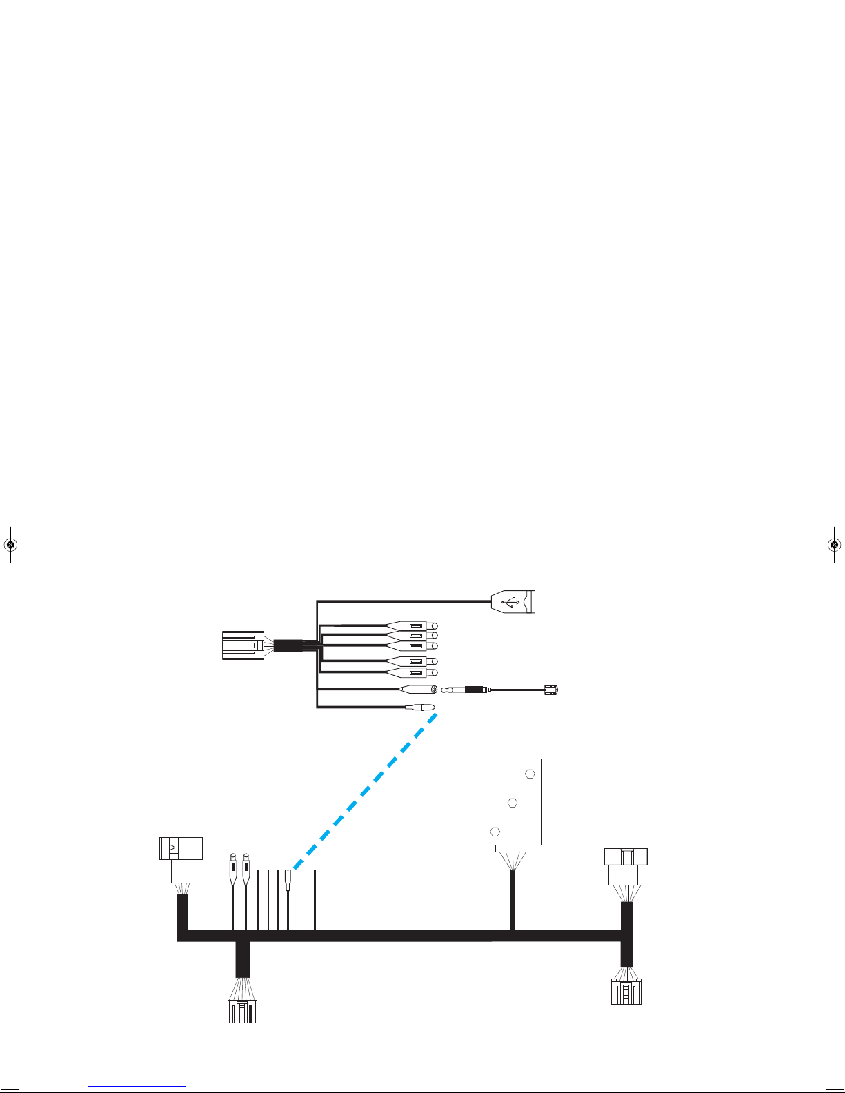
Media USB
Video out 1
Video out 2
DVR video input
AUX-IN video input
Reverse camera
Microphone
Reverse camera trigger
+B12V
ACC
GND
IR
Connect to car
original jack
Rear camera 2
Front video input
Reverse camera trigger
Power amplifier box
Connect to RW-50 interface
Connect to the
of car original head unit
power harness
Connect to car original head unit
Connect to OEM CD Housing
Connect to RW-50 interface
Connect to OEM screen plug
Connect to RW-50 Interface
F. Wiring Diagram
Harness 2
Harness 1
Plug A
Plug B
Plug C
Plug D
Plug E
2
Page 3
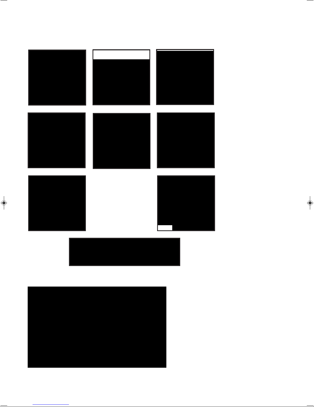
Prior to installing the unit, please make sure that you have all
the parts from the box and the necessary tools to complete the
installation.
1. RW-50/15 Fascia
2. RW-50/15 8” Interface
Screen
3. Harness 1 & Harness 2
4. Bluetooth External
Microphone
5. GPS External Antenna +
Bracket & Screws
6. Power Amplifier Box
7. Instruction Manual
8. Trim Tool
9. Rear Vision Camera
1. Trim tools
2. Cable tie
3. Soldering Iron & Solder
4. Electrical Tape
5. Heat shrink
6. Burner for Heat shrink
7. Small Terminal driver
8. Short Phillips head screwdriver
9. Multi tip set
10. Side cutters
11. Drill
12. Split conduit
13. Yellow Tongue (long strike, approx. 3-4 metres)
14. Short strike (approx. 1 metre)
1. RW-50/15 Fascia
4. Bluetooth External Microphone
5. GPS External Antenna +
Bracket & Screws
6. Power Amplifier Box
7. Instruction Manual
8. Trim Tool
9. Rear Vision Camera
3. Harness 1 & Harness 2
2. RW-50/15 8” Interface Screen
3
Parts - Packing List
Tools required
Page 4

Step 1 - Remove Air conditioning panel
1. Starting from the bottom, use trim tools
to removeair conditioning controls
2. Unplug harness and set
air conditioning controls aside
1. Use trim tools to
remove fascia panel
2. Gently pull fascia panel out
IMPORTANT
Before installing the RW50/15 please delete your original Bluetooth pairing from the OEM screen.
If this is not done - once the RW50/15 unit is installed - your phone will keep trying to pair
with the original Bluetooth.
3. Unplug button panel and set
OEM fascia panel aside
1. Remove 2 screws holding OEM
screen in place
2. Unplug harness and set OEM
screen aside
3. Remove 2 screws holding the
CD housing in place.
Step 2 - Remove Fascia Panel
Step 3 - Remove OEM Screen and CD Housing
4. Unplug harness and set OEM
CD housing aside for now.
4
WARNING
When removing the air-conditioning
panel, fascia, OEM screen and CD housing,
do not use excessive force to pull the
panels out as there are harnesses that
need to be unplugged before complete
removal.
Page 5

1.Remove door rubber and the
driver’s pillar trim
2. Mount microphone in the
top right hand corner of the
windscreen
3. Use lever to drop steering
wheel column down
4. Remove trim around
instrument cluster panel
7. Tape Bluetooth mic cable onto strike and pull through to the
instrument cluster panel area
5. Unplug instrument cluster
panel and remove
6. Feed short strike through A
piller hole and feed into the
instrument cluster panel area
8. You can now remove the tape
and feed the Bluetooth mic cable
into the
TOP SECTION
9. Tidy up cabling running down
the side of the driver’s piller and
reinstall rubber and trim
10. While the instrument cluster panel is removed we suggest feeding PLUG A & B lo-
cated on HARNESS 1 FROM the
CD HOUSING AREA up to the
TOP SECTION
(Please refer to page 8 for actual wiring diagram)
11. This will then leave PLUG C & D
from HARNESS 1 hanging in the
CD HOUSING AREA
Step 4 - Prepare all the cabling in preparation for
the head unit to be installed.
A. External Bluetooth Microphone
5
Page 6

B. IPOD & USB Cable
1. Remove glove box - gently push
in sides to release.
1. Attach GPS Antenna Bracket to
the back of RW50/15
Interface Screen
2. Place GPS Antenna on top of theBracket
3. Connect Antenna Plug into the
back of the RW50/15
Interface Screen
13. Plug harness back into
instrument cluster panel and
remount.
2. Unclip OEM USB and AUX cable
for now, so that you can remove the
glove box completely.
3. Feed RW50/15 USB cable
from top section down into the
glove box area
C. External Antenna
14. Reinstall trim.
NOTE: please make sure the bottom
section of the trim goes underneath
the two reset dials.
12. Connect PLUG A into OEM
plug located in the TOP SECTION
& Connect PLUG C into OEM plug
located in the
CD HOUSING AREA
6
Page 7

6. Connect camera plug to the extension cable.
Apply heat shrink over connection to avoid the
plug coming loose.
1. Run your long strike through chassis rail from front to rear.
2. Tape camera cable (large 4 pin din) onto strike at the rear of the vehicle.
3. Pull strike through from front of the vehicle - making sure that you leave enough cable at the
rear so that you can plug the camera cable in.
7. Remove kick panel and scuff plate on
passenger front side of vehicle
8. Lift carpet up to find grommet
9. Remove grommet and feed cable through
10. Use cutters to make an incision in
grommet so that you feed cable through it.
Once you have fed the cable through the
grommet restore grommet back into its
original position.
11. Pull excess cable then apply
conduit to all exposed cable.
12. Run reverse camera cable up into glove
box area.
13. Feed camera cable up to
top section
E. Rear Camera
14. Position HARNESS 2 up in the top
section and plug the camera cable
into the reverse camera plug input
15. Connect the reverse camera trigger
plugs from HARNESS 1 and
HARNESS 2 together
Notes:
Once you have repositioned the grommet after
feeding the reverse camera cable through,
we recommend applying silastic around the outside
the cable for waterproofing
Once you have fed the camera cable from the glove
box area up to the TOP SECTION, we recommend
that you cable tie any loose cables.
4. Attach the number plate camera onto
number plate (as shown above)
5. Mount number plate back
onto the vehicle.
7
Page 8

Step 5 - Mount OEM CD Housing
2. Connect PLUG D into the back of
OEM CD housing
3.
Plug the radio antenna into the
back of the OEM CD housing
4. Mount the CD housing back into
position and secure in place with the
original screws.
1. Before re-mounting the OEM CD
Housing we suggest positioning the
power amplifier box just behind it.
8
Media USB
Video out 1
Video out 2
DVR video input
AUX-IN video input
Reverse camera
Microphone
Reverse camera trigger
+B12V
ACC
GND
IR
Connect to car
original jack
Rear camera 2
Front video input
Reverse camera trigger
Power amplifier box
Connect to RW-50 interface
Connect to the
of car original head unit
power harness
Connect to car original head unit
Connect to OEM CD Housing
Connect to RW-50 interface
Connect to OEM screen plug
Connect to RW-50 Interface
F. Wiring Diagram
Harness 2
Harness 1
Plug A
Plug B
Plug C
Plug D
Plug E
• Plug all applicable cables into HARNESS 1 and HARNESS 2 (e.g. Bluetooth Mic, Media USB cable etc)
PLEASE NOTE:
If your Mazda BT-50 originally had the OEM GPS system installed, you
need to plug in a different radio antenna. Instead of using the radio
antenna that normally plugs into the back of the OEM CD housing
(the connector that you originally unplugged), you must use the radio
antenna that was originally plugged into the the back of the OEM
GPS Screen (it is the black connector).
Page 9

1. Grab the OEM fascia and
remove all 9 clips and set
aside.
5. Position the
button panel
and air
conditioning
vents onto the
RW-50/15
fascia and
secure in place
with the 10
original screws.
2. Remove the 10 screws holding the button
panel and air conditioning vents in place -
set aside.
4. Clip the 9 clips onto the
RW-50/15 fascia
Step 6 - Prepare the BT50 RW-50/15 fascia
OEM Fascia
3. Use the 4 screws supplied to mount
the interface screen onto the
RW-15/50 fascia panel.
RW50/15 Fascia
9
Page 10

Step 7 - Fascia installation
2. Plug the OEM button panel
harness into the back of the
OEM button panel
1. Connect PLUG B & E into the
back of the RW50/15
interface screen
3. Make sure all the cables are
tucked away neatly before securing
into place.
4. Rest the unit in place, test all
features first and then gently push
fascia panel back into position
5. Plug the OEM Air conditioning
control harnesses into the back of
the air conditioning control panel
6. Gently push air conditioning
controls back in.
7. Reposition Glove Box
10
Page 11

Steering Wheel Controls
Follow these steps to program in your steering wheel controls
• Go to main menu
• Touch setup
• Once in the settings menu, touch setup again
• Scroll down until you see SWC setup
• Simply filter through the different steering wheel controls
on the screen and follow the prompts.
Example:
Press the (volume down) icon on the screen and then press your (volume down)
button on your steering wheel to activate.
Continue this process until you have activated all of the steering wheel controls.
Please note: The voice recognition steering wheel control will now bring up the
Bluetooth feature.
11
 Loading...