

Page 1

2007 - 2008 IQ SNOWMOBILE
SERVICE MANUAL
FOREWORD
This service manual is designed prim arily for use by ce rtified Polaris Mas ter Service Dealer technicians in a properly
equipped shop and should be kept available for reference. All references to left and right side of the vehicle are from
the operator's perspective when seated in a normal riding position.
Some procedures outlined in this manual require a sound knowledge of mechanical theory, tool use, and shop
procedures in order to perform the work safely and correctly . T echnicians should read the text and be familiar with service
procedures before starting the work. Certa in procedur es require the use o f special tools. Use o nly the proper to ols as
specified.
Comments or suggestions about this manual may be d irected to: Service Publications Dept. @ Polaris Sales Inc. 2100
Hwy 55 Medina Minnesota 55340.
2007 - 2008 IQ Snowmobile Service Manual PN 9921044
© Copyright 2007 Polaris Sales Inc. All information contained within this publica tio n is based on th e late st prod uct informa tion at the time of publication. Due to constant
improvements in the design and quality of production componen ts, some minor discrep ancies may result between the actua l vehicle and the informatio n presented in this
publication. Depictions and/or procedures in this publication are intend ed for reference use only. No liability can be accept ed for omissions or inaccuracies. An y reprinting
or reuse of the depictions and/or procedures contained within, whether whole or in part, is expressly prohibited. Printed in U.S.A.
Page 2

UNDERSTANDING MANUAL SAFETY LABELS AND DIRECTIONS
Throughout this manual, important information is brought to your attention by the following symbols:
WARNING
SAFETY ALERT WARNING indicates a potential hazard that may result in severe injury or death to the operator,
bystander or person(s) inspecting or servicing the vehicle.
CAUTION
SAFETY ALERT CAUTION indicates a potential hazard that may result in minor personal injury or damage to the vehicle.
CAUTION
CAUTION indicates special precautions that must be taken to avoid vehicle damage or property damage.
NOTE:
NOTE provides key information by clarifying instructions.
IMPORTANT:
IMPORTANT provides key reminders during disassembly, assembly and inspection of components.
= In. / mm.
MEASUREMENT provides a key for a determined measurement specification.
= T
TORQUE provides a key for a required torque value.
TRADEMARKS
POLARIS ACKNOWLEDGES THE FOLLOWING PRODUCTS MENTIONED IN THIS MANUAL:
Loctite, Registered Trademark of the Loctite Corporation
Nyogel, Trademark of Wm. F. Nye Co.
Fluke, Registered Trademark of John Fluke Mfg. Co.
Mity-Vac, Registered Trademark of Neward Enterprises, Inc.
Torx, Registered Trademark of Textron
M-10, Registered Trademark of FAST Inc.
WD-40, Registered Trademark of WD-40 Company
Rapid Reaction Driven Clutch, Registered Trademark of Team Industries Inc.
VM and TM Carburetors, Registered Trademarks of Mikuni Amer ica n Corp or ation
Fox and Fox PS-5 Registered Trademark of Fox Racin g Shox, Inc.
Ryde FX and Air 2.0, Registered Trademark of Arvin Meritor, Inc.
Walker Evans Air Shock, Registered Trademark of Walker Evans Racing, Inc.
Page 3

2007 - 2008 IQ Snowmobile
Service Manual Chapters
Model Specifications........................... ....1
General Information............................ ....2
Maintenance....................................... ....3
Fuel Systems...................................... ....4
Engine Systems.................................. ....5
Final Drive and Brake Systems.......... ....6
PVT System........................................ ....7
Suspension and Steering.................... ....8
Shocks................................................ ....9
Chassis............................................... ....10
Electrical Systems.............................. ....11
Wiring Schematics.............................. ....12
Page 4

Model Specifications
CHAPTER 1
Model Specifications
SPECIFICATIONS. . . . . . . . . . . . . . . . . . . . . . . . . . . . . . . . . . . . . . . . . . . . . . . . . . . . . . . 1.2
2007 600 HO IQ . . . . . . . . . . . . . . . . . . . . . . . . . . . . . . . . . . . . . . . . . . . . . . . . . . . . . . . .1.2
2007 600 HO SWITCHBACK . . . . . . . . . . . . . . . . . . . . . . . . . . . . . . . . . . . . . . . . . . . . . .1.4
2007 600 HO RMK . . . . . . . . . . . . . . . . . . . . . . . . . . . . . . . . . . . . . . . . . . . . . . . . . . . . . .1.6
2007 600 HO IQ CFI. . . . . . . . . . . . . . . . . . . . . . . . . . . . . . . . . . . . . . . . . . . . . . . . . . . . .1.8
2007 600 HO SWITCHBACK CFI. . . . . . . . . . . . . . . . . . . . . . . . . . . . . . . . . . . . . . . . . .1.10
2007 600 HO IQ LX CFI . . . . . . . . . . . . . . . . . . . . . . . . . . . . . . . . . . . . . . . . . . . . . . . . .1.12
2007 600 HO IQ TOURING CFI . . . . . . . . . . . . . . . . . . . . . . . . . . . . . . . . . . . . . . . . . . .1.14
2007 700 HO IQ DRAGON. . . . . . . . . . . . . . . . . . . . . . . . . . . . . . . . . . . . . . . . . . . . . . .1.16
2007 700 HO RMK DRAGON. . . . . . . . . . . . . . . . . . . . . . . . . . . . . . . . . . . . . . . . . . . . .1.18
2008 IQ SHIFT . . . . . . . . . . . . . . . . . . . . . . . . . . . . . . . . . . . . . . . . . . . . . . . . . . . . . . . .1.20
2008 600 RMK 144 / 600 RMK SHIFT 155. . . . . . . . . . . . . . . . . . . . . . . . . . . . . . . . . . .1.22
2008 600 DRAGON IQ . . . . . . . . . . . . . . . . . . . . . . . . . . . . . . . . . . . . . . . . . . . . . . . . . .1.24
2008 600 SWITCHBACK / 600 DRAGON SWITCHBACK. . . . . . . . . . . . . . . . . . . . . . .1.26
2008 600 IQ LX. . . . . . . . . . . . . . . . . . . . . . . . . . . . . . . . . . . . . . . . . . . . . . . . . . . . . . . .1.28
2008 600 IQ TOURING. . . . . . . . . . . . . . . . . . . . . . . . . . . . . . . . . . . . . . . . . . . . . . . . . .1.30
2008 600 RMK 155. . . . . . . . . . . . . . . . . . . . . . . . . . . . . . . . . . . . . . . . . . . . . . . . . . . . .1.32
2008 700 IQ / 700 DRAGON IQ . . . . . . . . . . . . . . . . . . . . . . . . . . . . . . . . . . . . . . . . . . .1.34
2008 700 SWITCHBACK / 700 DRAGON SWITCHBACK. . . . . . . . . . . . . . . . . . . . . . .1.36
2008 700 RMK 155 / 700 DRAGON RMK 155 / 163 . . . . . . . . . . . . . . . . . . . . . . . . . . .1.38
2008 800 DRAGON RMK 155 / 163. . . . . . . . . . . . . . . . . . . . . . . . . . . . . . . . . . . . . . . .1.40
1
1.1
Page 5
Model Specifications
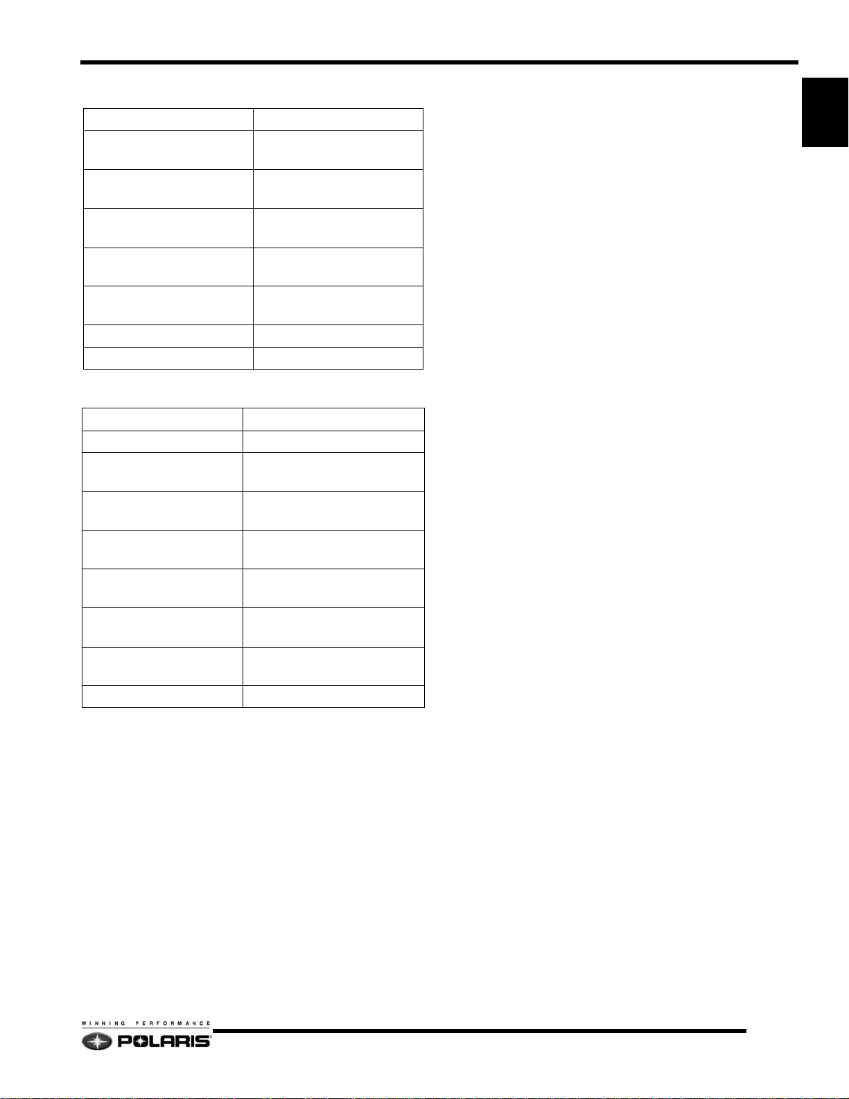
SPECIFICATIONS
2007 600 HO IQ
Model Number: S07PP6FS (A) (B)
Engine
Engine Type
Model Number S3273-6044-PF6F
Displacement / # Cylinders 599cc / 2
Bore (inches/mm) 3.04 / 77.25
Stroke (inches/mm) 2.52 / 64
Piston to Cylinder Clearance
(inches/mm)
Installed Ring Gap
(inches / mm)
Operating RPM ±200 8100
Idle RPM 1500
Engagement RPM ±200 3800
Exhaust Valve Spring Pink
Carburetor Settings
Type
Main Jet
Pilot Jet
Jet Needle/Clip position
Needle Jet
Throttle Gap (Under Cutaway) (in/mm)
Cutaway
Valve Seat
Starter Jet
Pilot Air Jet
Fuel screw (Turns Out)
Recommended Fuel Octane (R+M/2)
Liberty Liquid-Cooled /
Case Reed Induction
.004 - .006 / .105 - .159
.014 - .020 / .356 - .508
Mikuni TM38
420
50
9DGN6-57 / 2
P-8
0.08 / 2.1
1.5 Notch
1.5
145
.6
1.25
91
(Non-Oxygenated)
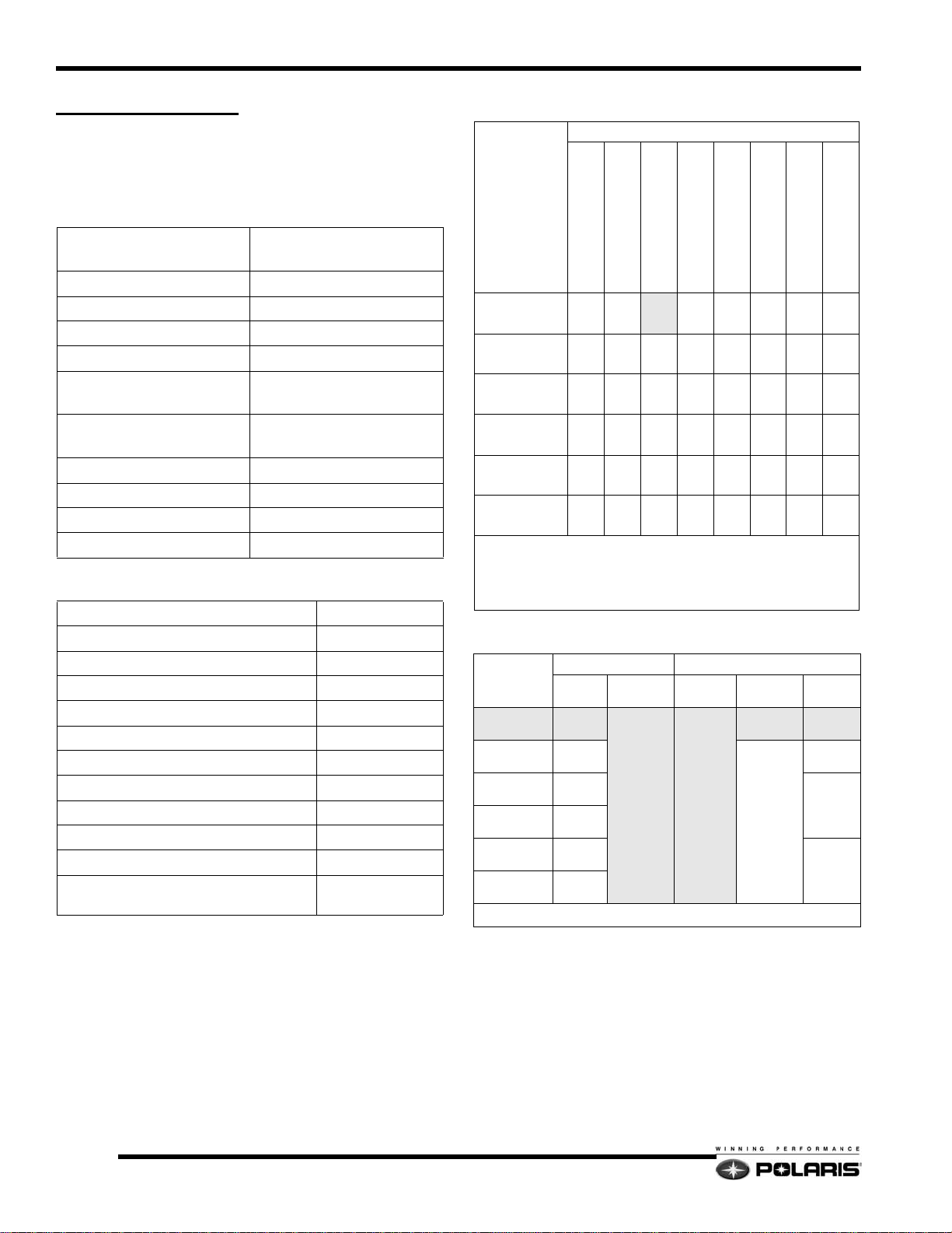
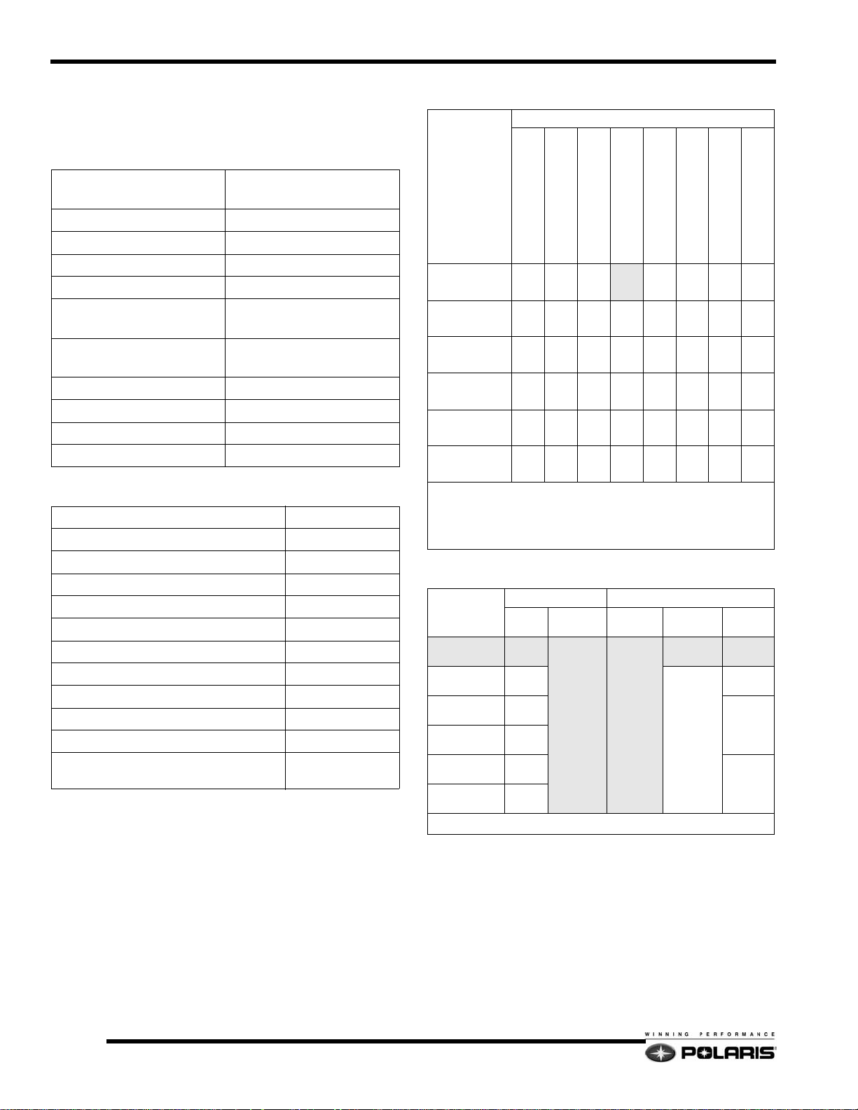
Carburetor Jetting
Ambient Temperature
Altitude
Meters (feet)
< -25°F/<-35°C
0°F to +20°F/-18°C to -7°C
+15°F to +35°F/-9°C to +2°C
+30°F to +50°F/-1°C to +10°C
+45°F to +65°F/+7°C to +18°C
#1
#1
#1
#1
#1
#1
0-600
(0-2000)
600-1200
(2000-4000)
1200-1800
(4000-6000)
1800-2400
(6000-8000)
2400-3000
(8000-10000)
3000-3700
(10000-12000)
-15°F to +5°F/-26°C to -15°C
-30°F to -10°F/-34°C to -23°C
440#3430#3420#2400#2390#2380#2370#2360
410#3400#3390#2370#2360#2350#2340#1330
370#3360#2350#2340#2330#2320#1310#1300
340#3320#2310#2300#2280#2280#1270#1260
310#2300#2290#2280#1270#1260#1250#1240
290#2280#2270#1250#1240#1230#1220#1210
When using non oxygenated fuel with a RON greater than 93,
decrease the main jet number in the above chart by 10 and raise the
E-clip one position. If the chart recommends clip #1, install washer
on top when using RON 93.
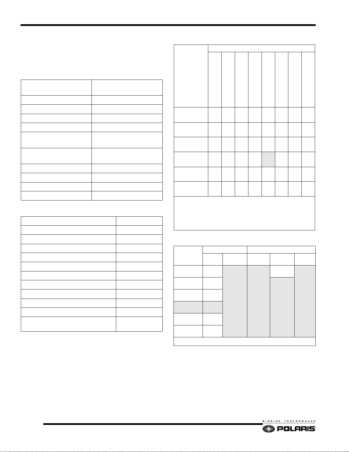
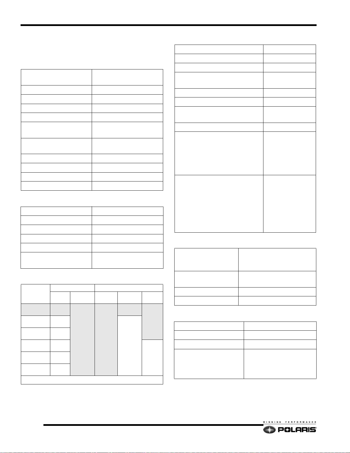
Clutch Settings
ALTITUDE
meters
(feet)
0-600
(0-2000)
600-1200
(2000-4000)
1200-1800
(4000-6000)
1800-2400
(6000-8000)
2400-3000
(8000-10000)
3000-3600
(10000-12000)
DRIVE CLUTCH DRIVEN CLUTCH
Shift
Weight
10-62
10-60
10-58
10-56
10-54
10-AL
Clutch
Spring
BLK / GRN
(120 / 340)
(7042083)
Clutch
Spring
RED/BLK
(140 / 240)
(7043058)
Driven
Helix
64/42.36
LW ER
56/42 - .36
LW ER
Drive Clutch Bolt Torque: 50 lb.ft. (68Nm)
Gearing
23:39-76
22:39-76
22:40-76
20:41-76
>+60°F/>+16°C
1.2
Page 6

Model Specifications
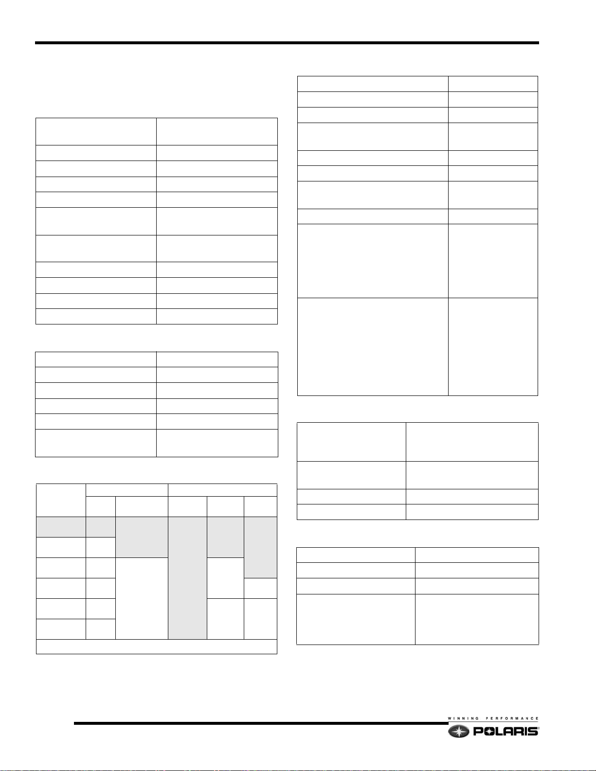
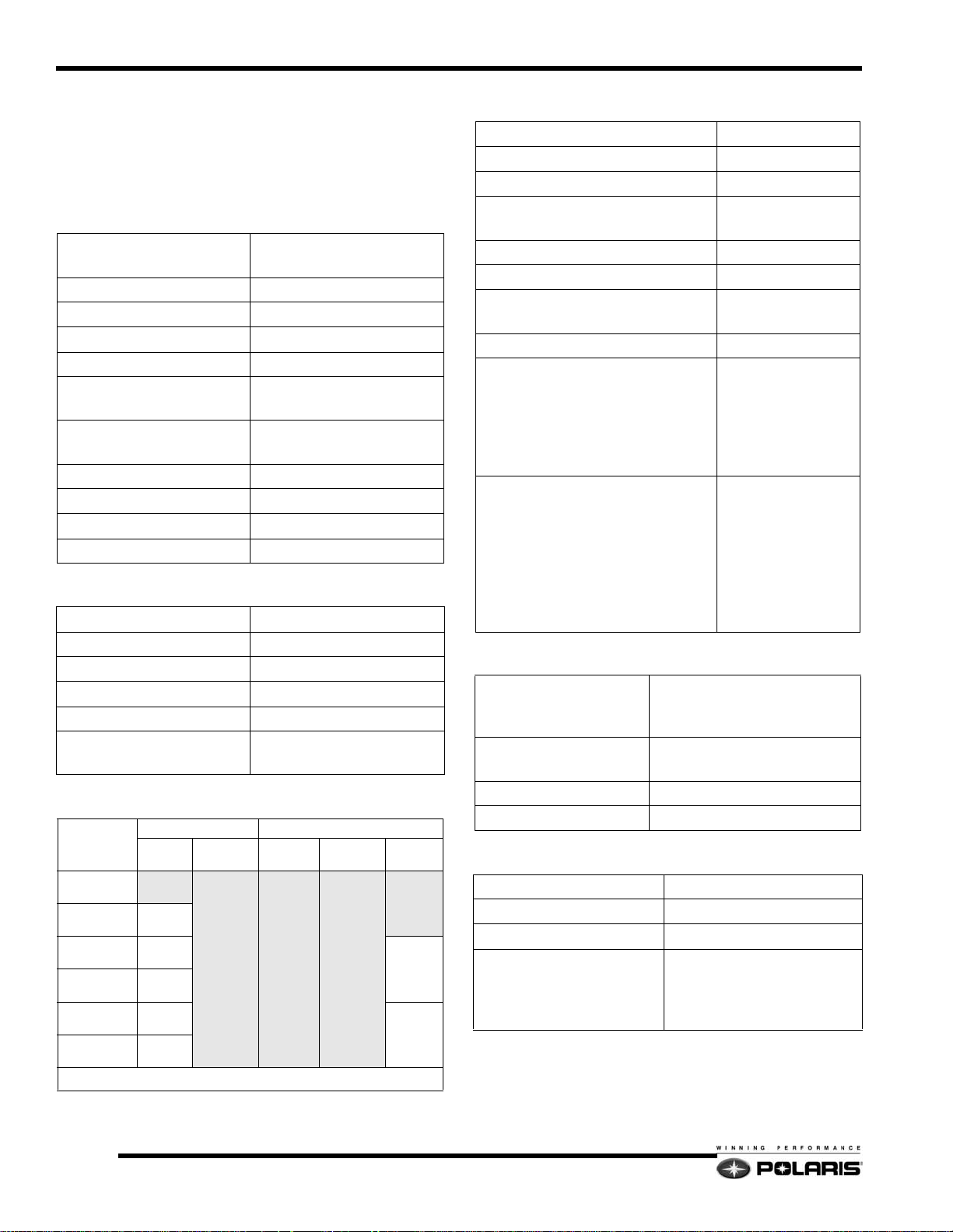
General
Width (in/cm) 48 / 121.9
Length (in/cm) 115 / 292.1
Height (in/cm) 48 / 121.9
Estimated Dry Weight
(lb/kg)
Fuel (Gallons / Liters) 10.8 / 40.9
Oil (Quarts / Liters) 3.4 / 3.2
Cooling System Capacity
(Quarts / Liters)
Brake Fluid DOT 4
Drive Belt
Part Number
Width (inches / cm)
Side Angle
Circumference (inches / cm)
Center Distance (inches / cm)
Chaincase
Center Distance (inches)
Top Gear (Stock)
Bottom Gear (Stock)
Chain (Stock)
Gear Lube
Capacity (oz / ml)
Reverse System
Electrical
Alternator Output
Operating Voltage
Watts @ 13.5 Vdc (Total)
Ignition Timing
Spark Plug Gap in.(mm) .027 (.70)
Spark Plug Champion RN57YCC
CDI Marking 4011033
Flywheel Marking 4010677
Track
475 / 215.7
6.3 / 6
3211080
1.438 / 3.65
28_
46.625 / 118.4
11.5 / 29.2
8.373
23
39
76
Polaris Synthetic
11 / 325.3
Perc
13.5 - 14.5 Vdc
280
26_ @3500 RPM
(TPS Un-plugged)
Front Suspension
Suspension Type IQ 42.5
Ryde FX HPG w/IFP (STD.)
(Rebuidlable)
Shocks
IFS Spring Rate
lbs/in (N/mm)
Spring Installed Length
Inches (cm)
Front Vertical Travel
Inches (cm)
Suspension Setup
Width
Inches (cm)
Camber Inches (cm) 2.25 ± 0.31 (57 ± 7.9)
Toe Out Inches (cm) 0 - 0.12 (0 - 0.31)
Suspension Type IQ 121
Front Track Shock (FTS)
FTS Spring Rate
lbs/in (N/mm)
FTS Spring Installed
Length Inches (cm)
Rear Track Shock (RTS)
Torsion Spring Diameter
Tail Angle
Rear Travel Inches (cm) 13.9 (35.3)
Fox Compression Adj. Remote
Resevoir HPG (OPT.)
(Rebuidable)
100 (17.5)
10.55 (26.8)
10 (25.4)
41.16 (104.54)
Rear Suspension
Ryde FX HPG w/IFP (STD.)
(Rebuildable)
Fox HPG w/IFP (OPT.)
(Rebuildable)
130 - 270 (23 - 47)
7.97 (20.2)
Fox PS5 w/IFP (STD.)
(Rebuildable)
Fox Compression Adjustable
Remote Resevoir HPG (OPT.)
(Rebuildable)
.374
80_
1
Width - Inches (cm) 15 (38)
Length - Inches (cm) 121 (307)
Lug Height - Inches (cm)
Track tension sag in/cm with
10 lbs/4.54kg placed 16 in/
40cm ahead of rear idler
shaft
7/8
1.0 / (2.5)
1.25 (3.175) - Option
″ - 1-1/8″(2.2 - 2.9cm)
1.3
Page 7

Model Specifications
2007 600 HO Switchback
Model Number: S07PS6FS (A)
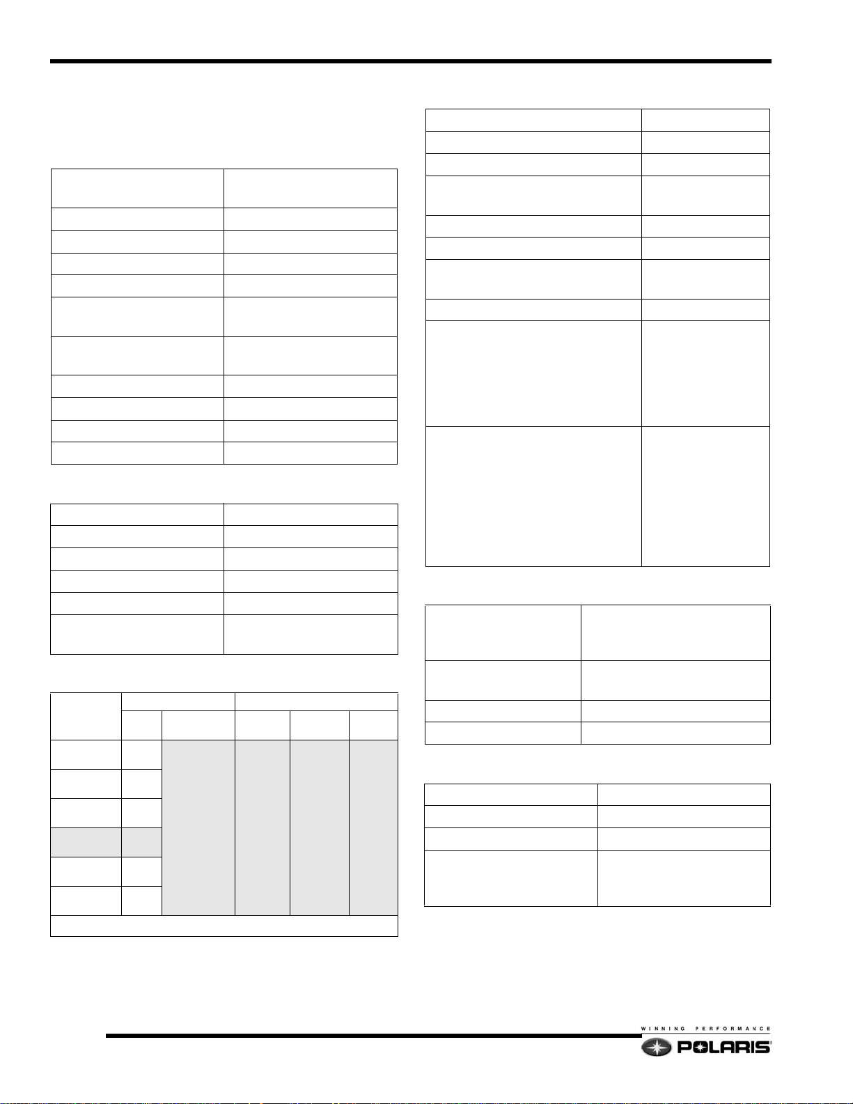
Engine
Engine Type
Model Number S3273-6044-PF6F
Displacement / # Cylinders 599cc / 2
Bore (inches/mm) 3.04 / 77.25
Stroke (inches/mm) 2.52 / 64
Piston to Cylinder Clearance
(inches/mm)
Installed Ring Gap
(inches / mm)
Operating RPM ±200 8100
Idle RPM 1500
Engagement RPM ±200 3800
Exhaust Valve Spring Pink
Carburetor Settings
Type
Main Jet
Pilot Jet
Jet Needle/Clip position
Needle Jet
Throttle Gap (Under Cutaway) (in/mm)
Cutaway
Valve Seat
Starter Jet
Pilot Air Jet
Fuel screw (Turns Out)
Recommended Fuel Octane (R+M/2)
Liberty Liquid-Cooled /
Case Reed Induction
.004 - .006 / .105 - .159
.014 - .020 / .356 - .508
Mikuni TM38
420
50
9DGN6-57 / 2
P-8
0.08 / 2.1
1.5 Notch
1.5
145
.6
1.25
91
(Non-Oxygenated)
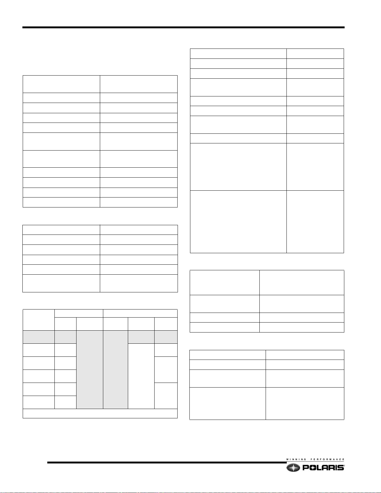
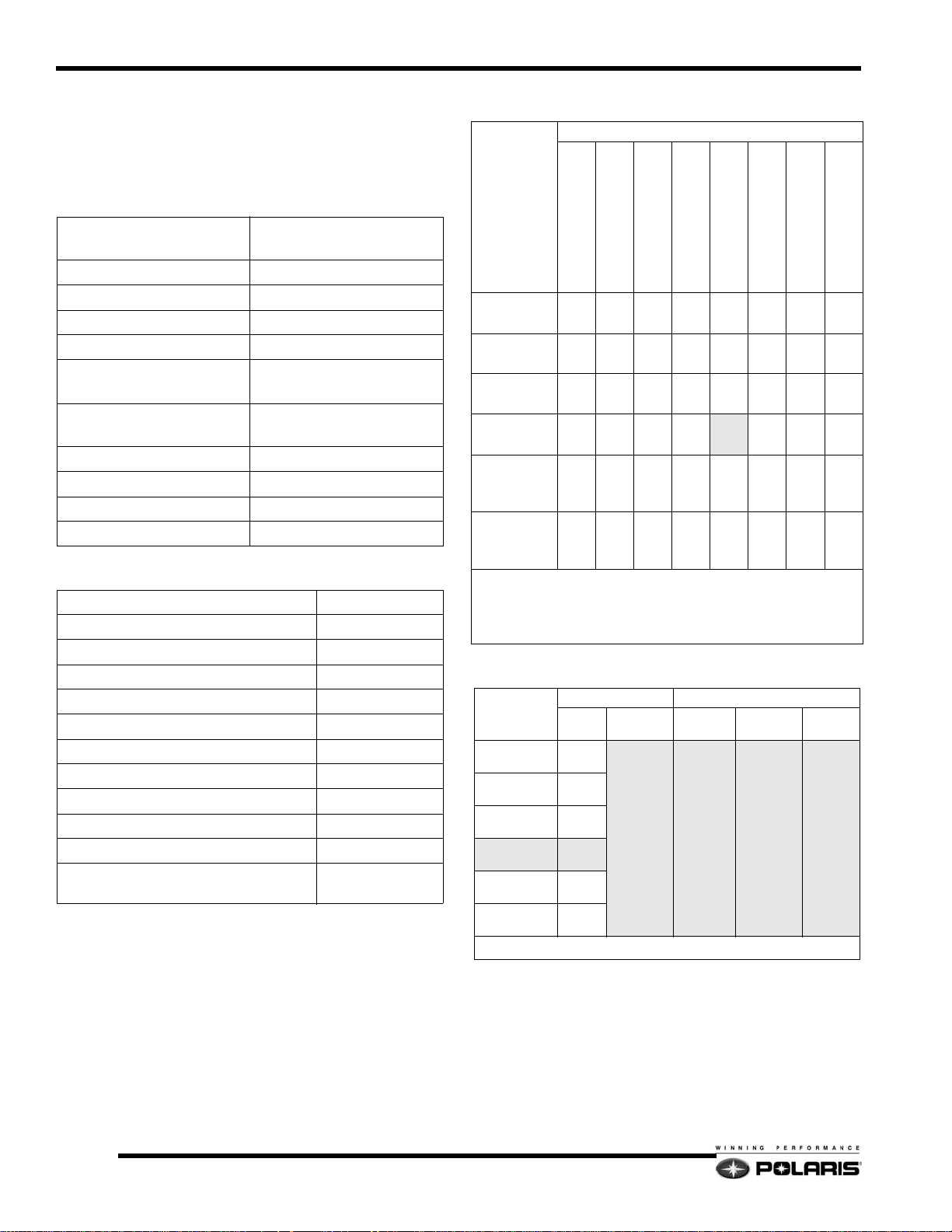
Carburetor Jetting
Ambient Temperature
Altitude
Meters (feet)
< -25°F/<-35°C
0°F to +20°F/-18°C to -7°C
+15°F to +35°F/-9°C to +2°C
+30°F to +50°F/-1°C to +10°C
+45°F to +65°F/+7°C to +18°C
#1
#1
#1
#1
#1
#1
0-600
(0-2000)
600-1200
(2000-4000)
1200-1800
(4000-6000)
1800-2400
(6000-8000)
2400-3000
(8000-10000)
3000-3700
(10000-12000)
-15°F to +5°F/-26°C to -15°C
-30°F to -10°F/-34°C to -23°C
440#3430#3420#2400#2390#2380#2370#2360
410#3400#3390#2370#2360#2350#2340#1330
370#3360#2350#2340#2330#2320#1310#1300
340#3320#2310#2300#2280#2280#1270#1260
310#2300#2290#2280#1270#1260#1250#1240
290#2280#2270#1250#1240#1230#1220#1210
When using non oxygenated fuel with a RON greater than 93,
decrease the main jet number in the above chart by 10 and raise the
E-clip one position. If the chart recommends clip #1, install washer
on top when using RON 93.
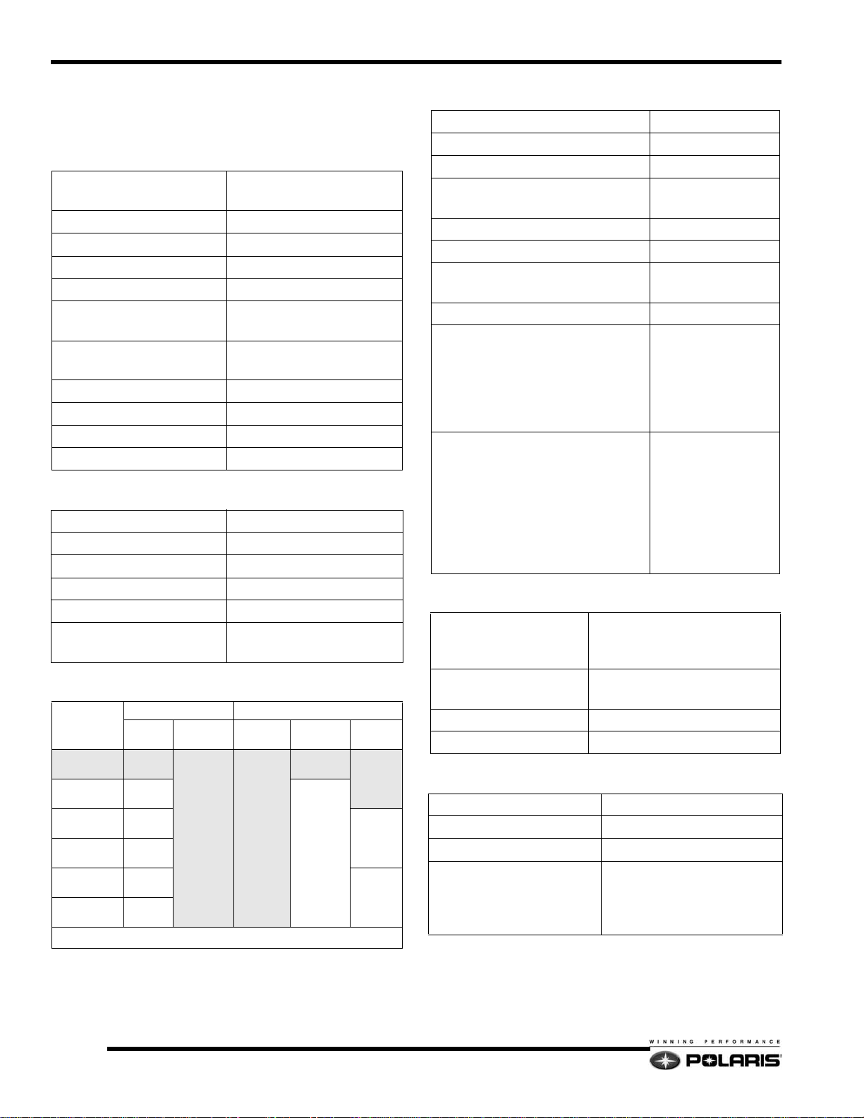
Clutch Settings
ALTITUDE
meters
(feet)
0-600
(0-2000)
600-1200
(2000-4000)
1200-1800
(4000-6000)
1800-2400
(6000-8000)
2400-3000
(8000-10000)
3000-3600
(10000-12000)
DRIVE CLUTCH DRIVEN CLUTCH
Shift
Weight
10-62
10-60
10-58 22:40-76
10-56
10-54
10-AL
Clutch
Spring
BLK / GRN
(120 / 340)
(7042083)
Clutch
Spring
RED/BLK
(140 / 240)
(7043058)
Driven
Helix
64/42-.36
LW ER
56/42 - .36
LW ER
Drive Clutch Bolt Torque: 50 lb.ft. (68Nm)
Gearing
22:39-76
20:41-76
>+60°F/>+16°C
1.4
Page 8

Model Specifications
General
Width (in/cm) 48 / 121.9
Length (in/cm) 125 / 317.5
Height (in/cm) 48 / 121.9
Estimated Dry Weight
(lb/kg)
Fuel (Gallons / Liters) 10.8 / 40.9
Oil (Quarts / Liters) 3.4 / 3.2
Cooling System Capacity
(Quarts / Liters)
Brake Fluid DOT 4
Drive Belt
Part Number
Width (inches / cm)
Side Angle
Circumference (inches / cm)
Center Distance (inches / cm)
Chaincase
Center Distance (inches)
Top Gear (Stock)
Bottom Gear (Stock)
Chain (Stock)
Gear Lube
Capacity (oz / ml)
Reverse System
Electrical
Alternator Output
Operating Voltage
Watts @ 13.5 Vdc (Total)
Ignition Timing
Spark Plug Gap in.(mm) .027 (.70)
Spark Plug Champion RN57YCC
CDI Marking 4011033
Flywheel Marking 4010677
Track
483 / 219.3
6.3 / 6
3211080
1.438 / 3.65
28_
46.625 / 118.4
11.5 / 29.2
8.373
22
39
76
Polaris Synthetic
11 / 325.3
Perc
13.5 - 14.5 Vdc
280
26_ @3500 RPM
(TPS Un-plugged)
Front Suspension
Suspension Type IQ 42.5
Fox HPG w/IFP (STD.)
(Rebuidlable)
Shocks
IFS Spring Rate
lbs/in (N/mm)
Spring Installed Length
Inches (cm)
Front Vertical Travel
Inches (cm)
Ski Center Distance
Inches (cm)
Camber Inches (cm) 2.25 ± 0.31 (57 ± 7.9)
Toe Out Inches (cm) 0 - 0.12 (0 - 0.31)
Suspension Type IQ 144
Front Track Shock (FTS)
FTS Spring Rate
lbs/in (N/mm)
FTS Spring Installed
Length Inches (cm)
Rear Track Shock (RTS)
Torsion Springs
Rear Travel Inches (cm) 13.9 (35.3)
Fox Compression Adj. Remote
Resevoir HPG (OPT.)
(Rebuidable)
100 (17.5)
10.55 (26.8)
10 (25.4)
42.5 (108)
Rear Suspension
Fox HPG w/IFP
(Rebuildable)
170 (30)
7.25 (18.4)
Fox Compression Adjustable
Remote Resevoir HPG
(Rebuildable)
.359 Square / 77_ (Stock)
.347 / 77_ / (Soft)
- PN 7041627 - 067
- PN 7041628 - 067
.375 / 77_ / (Firm)
- PN 7041942 - 067
- PN 7041943 - 067
1
Width - Inches (cm) 15 (38)
Length - Inches (cm) 144 (366)
Lug Height - Inches (cm)
Track tension sag in /cm with
10 lbs/4.54kg placed 16 in/
40cm ahead of rear idler
shaft
1.25 (3.175) (STD.)
1.50 (3.8) (OPT.)
3/8
″- 1/2″ (1 - 1.3cm)
1.5
Page 9
Model Specifications
2007 600 HO RMK
Model Number:
144 = S07PK6FS / S07PK6FE
155 = S07PM6FS (A)
Engine
Engine Type
Model Number S3273-6044-PF6F
Displacement / # Cylinders 599cc / 2
Bore (inches/mm) 3.04 / 77.25
Stroke (inches/mm) 2.52 / 64
Piston to Cylinder Clearance
(inches/mm)
Installed Ring Gap
(inches / mm)
Operating RPM ±200 8100
Idle RPM 1500
Engagement RPM ±200 3800
Exhaust Valve Spring Pink
Carburetor Settings
Type
Main Jet
Pilot Jet
Jet Needle/Clip position
Needle Jet
Throttle Gap (Under Cutaway) (in/mm)
Cutaway
Valve Seat
Starter Jet
Pilot Air Jet
Fuel screw (Turns Out)
Recommended Fuel Octane (R+M/2)
Liberty Liquid-Cooled /
Case Reed Induction
.004 - .006 / .105 - .159
.014 - .020 / .356 - .508
Mikuni TM38
280
50
9DGN6-57 / 1
P-8
0.13 / 3.2
2.5
1.5
145
.6
1
91
(Non-Oxygenated)
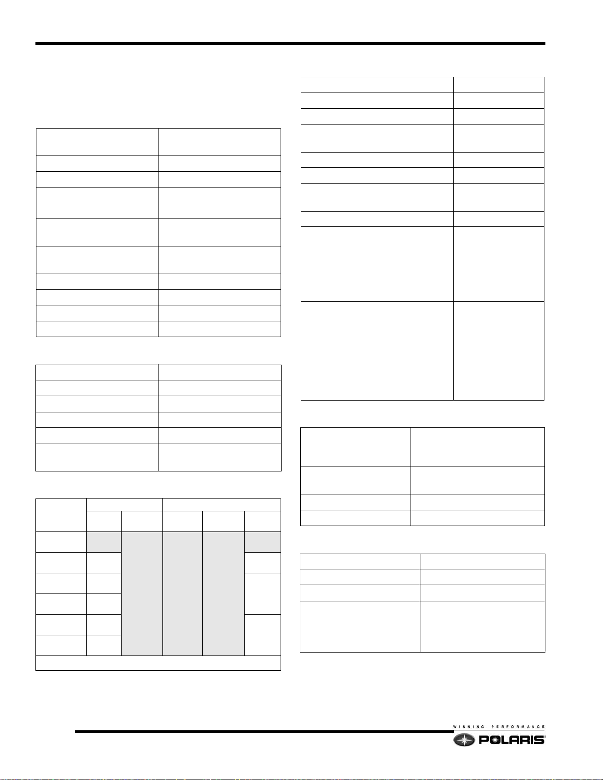
Carburetor Jetting
Ambient Temperature
Altitude
Meters (feet)
< -25°F/<-35°C
0°F to +20°F/-18°C to -7°C
+15°F to +35°F/-9°C to +2°C
+30°F to +50°F/-1°C to +10°C
+45°F to +65°F/+7°C to +18°C
#1
#1
#1
#1
#1
**
0-600
(0-2000)
600-1200
(2000-4000)
1200-1800
(4000-6000)
1800-2400
(6000-8000)
2400-3000
(8000-10000)
3000-3700
(10000-12000)
-15°F to +5°F/-26°C to -15°C
-30°F to -10°F/-34°C to -23°C
440#3430#3420#2400#2390#2380#2370#2360
410#3400#3390#2370#2360#2350#2340#1330
370#3360#2350#2340#2330#2320#1310#1300
340#3320#2310#2300#2280#1280#1270#1260
310#2300#2290#2280#1270#1260#1250#1240
290#2280#2270#1250#1240**230**220**210
** = Clip in # 1 position with washer placed on top of clip. When
using non-oxygenated fuel with a RON greater than 93, decrease the
main jet number in the above chart by 10 and raise the E-clip one
position. If the chart recommends **, do nothing with the clip when
using RON 93.
Clutch Settings
ALTITUDE
meters
(feet)
0-600
(0-2000)
600-1200
(2000-4000)
1200-1800
(4000-6000)
1800-2400
(6000-8000)
2400-3000
(8000-10000)
3000-3600
(10000-12000)
DRIVE CLUTCH DRIVEN CLUTCH
Shift
Weight
10-62
10-60
10-58
10-56
10-54
10-AL
Clutch
Spring
BLK / GRN
(120 / 340)
(7042083)
Clutch
Spring
RED/BLK
(140 / 240)
(7043058)
Driven
Helix
64/42-.36
LW ER
56/42 - .36
LW ER
Drive Clutch Bolt Torque: 50 lb.ft. (68Nm)
Gearing
19:41-76
>+60°F/>+16°C
1.6
Page 10

Model Specifications
General
Width (in/cm) 46.5 / 118.1
Length (in/cm)
Height (in/cm) 49 / 124.5
Estimated Dry Weight
(lb/kg)
Fuel (Gallons / Liters) 12 / 45.4
Oil (Quarts / Liters) 3.4 / 3.2
Cooling System Capacity
(Quarts / Liters)
Brake Fluid DOT 4
Drive Belt
Part Number
Width (inches / cm)
Side Angle
Circumference (inches / cm)
Center Distance (inches / cm)
Chaincase
Center Distance (inches)
Top Gear (Stock)
Bottom Gear (Stock)
Chain (Stock)
Gear Lube
Capacity (oz / ml)
Reverse System
Electrical
Alternator Output
Operating Voltage
Watts @ 13.5 Vdc (Total)
Ignition Timing
Spark Plug Gap in.(mm) .027 (.70)
Spark Plug Champion RN57YCC
CDI Marking 4011033
Flywheel Marking 4010677
Track
Width - Inches (cm) 15 (38)
Length - Inches (cm)
Lug Height - Inches (cm) 2.0(5) or 2.4(6.1)
Track tension sag in /cm with
10 lbs/4.54kg placed 16 in/
40cm ahead of rear idler
shaft
144 = 125 / 318
155 = 130 / 330.2
144 = 472 / 214.3
155 = 478 / 217
6.3 / 6
3211115
1.460 / 3.7
26_
46.77 / 118.8
11.5 / 29.2
8.373
Polaris Synthetic
11 / 325.3
Perc
13.5 - 14.5 Vdc
280
26_ @3500 RPM
(TPS Un-plugged)
144 (325)
155 (393.7)
3/8
″- 1/2″ (1 - 1.3cm)
19
41
76
Front Suspension
Suspension Type IQ RMK Adjustable
Ryde FX Compression Adjustable
Shocks
IFS Spring Rate
lbs/in (N/mm)
Spring Installed Length
Inches (cm)
WE Air Oil Volume 95cc
WE Air Nitrogen
Charge
Stock
Optional
Front Vertical Travel
Inches (cm)
Ski Center Distance
Inches (cm)
Camber Inches (cm) 2.17 ± 0.31 (55 ± 7.9)
Toe Out Inches (cm) 0 - 0.12 (0 - 0.31)
Rear Suspension
Suspension Type IQ 144 / 155
Front Track Shock (FTS)
FTS Spring Rate
lbs/in (N/mm)
FTS Spring Installed
Length Inches (cm)
Rear Track Shock (RTS)
WE Air Oil Volume 70cc
WE Air Nitrogen Charge
Stock
Optional
Torsion Springs
Rear Travel Inches (cm)
Walker Evans Air (OPT.)
39(99.1) / 40(101.6) / 41(104.1)
.359 Square / 77_ (Stock)
.347 / 77_ / (Soft)
- PN 7041627 - 067
- PN 7041628 - 067
.375 / 77_ / (Firm)
- PN 7041942 - 067
- PN 7041943 - 067
(STD.)
(Rebuidable)
100 (17.5)
10.35 (26.3)
215 psi
220 - 225 psi
9 (22.9)
Ryde FX (STD.)
Walker Evans Air (OPT.)
190 (33)
7.4 (18.8)
Ryde FX (STD.)
Walker Evans Air (OPT.)
(Rebuildable)
215 psi
210 - 220 psi
144 = 14.5(36.8)
155 = 15.5(39.4)
1
1.7
Page 11
Model Specifications
2007 600 HO IQ CFI
Model Number: S07PP6HS (A) (B)
Engine
Engine Type
Model Number S3206-6044-PF6H
Displacement / # Cylinders 599cc / 2
Bore (inches/mm) 3.04 / 77.25
Stroke (inches/mm) 2.52 / 64
Piston to Cylinder Clearance
(inches/mm)
Installed Ring Gap
(inches / mm)
Operating RPM ±200 8250
Idle RPM 1700
Engagement RPM ±200 3800
Exhaust Valve Spring Purple
Fuel Delivery
Type Cleanfire Direct Injection
Throttle Body Marking 1203213
Throttle Body Bore 46mm
TPS Voltage @ Idle 0.95 +/- 0.01 Vdc
Fuel Pressure - PSI (bar) 58 (4.0)
Recommended Fuel Octane
(R+M/2)
Clutch Settings
ALTITUDE
meters
(feet)
0-600
(0-2000)
600-1200
(2000-4000)
1200-1800
(4000-6000)
1800-2400
(6000-8000)
2400-3000
(8000-10000)
3000-3600
(10000-12000)
DRIVE CLUTCH DRIVEN CLUTCH
Shift
Weight
10-62
10-60
10-58
10-56
10-54
10-AL
Drive Clutch Bolt Torque: 80 lb.ft. (108Nm)
Clutch
Spring
BLK / GRN
(120 / 340)
(7042083)
Liberty Liquid-Cooled /
Case Reed Induction
.004 - .006 / .105 - .159
.014 - .020 / .356 - .508
91 Non-Oxygenated
Clutch
Spring
RED/BLK
(140 / 240)
(7043058)
Driven
Helix
64/42.36
LW ER
56/42 - .36
LW ER
23:39-76
22:39-76
22:40-76
20:41-76
Gearing
General
Width (in/cm) 48 / 121.9
Length (in/cm) 115 / 292.1
Height (in/cm) 48 / 121.9
Estimated Dry Weight
(lb/kg)
485 / 220.2
Fuel (Gallons / Liters) 11.7 / 44.3
Oil (Quarts / Liters) 3.4 / 3.2
Cooling System Capacity
(Quarts / Liters)
6.3 / 6
Brake Fluid DOT 4
Drive Belt
Part Number
Width (inches / cm)
Side Angle
Circumference (inches / cm)
Center Distance (inches / cm)
3211080
1.438 / 3.65
28_
46.625 / 118.4
11.5 / 29.2
Chaincase
Center Distance (inches)
Top Gear (Stock)
Bottom Gear (Stock)
Chain (Stock)
Gear Lube
Capacity (oz / ml)
Reverse System
8.373
23
39
76
Polaris Synthetic
11 / 325.3
Perc
Electrical
Alternator Output
Operating Voltage
Watts @ 13.5 Vdc (Total)
Ignition Timing
Coolant Temp = 120_F (49_C)
13.5 - 14.5 Vdc
400
18_ @1700 RPM
Spark Plug Gap in.(mm) .027 (.70)
Spark Plug C hampion RN57YCC
Track
Width - Inches (cm) 15 (38)
Length - Inches (cm) 121 (307)
Lug Height - Inches (cm)
1.0 (5) (STD.)
1.25 (3.175) (OPT.)
Track tension sag in/cm with
10 lbs/4.54kg placed 16 in/
40cm ahead of rear idler
7/8
″ - 1-1/8″(2.2 - 2.9cm)
shaft
1.8
Page 12

Front Suspension
Model Specifications
Suspension Type IQ 42.5
Ryde FX HPG w/IFP (STD.)
(Rebuidlable)
Shocks
IFS Spring Rate
lbs/in (N/mm)
Spring Installed Length
Inches (cm)
Front Vertical Travel
Inches (cm)
Ski Center Distance
Inches (cm)
Camber Inches (cm) 2.25 ± 0.31 (57 ± 7.9)
Toe Out Inches (cm) 0 - 0.12 (0 - 0.31)
Suspension Type IQ 121
Front Track Shock (FTS)
FTS Spring Rate
lbs/in (N/mm)
FTS Spring Installed
Length Inches (cm)
Rear Track Shock (RTS)
Torsion Spring Diameter
T ail Angle
Rear Travel Inches (cm) 13.9 (35.3)
Fox Compression Adj. Remote
Resevoir HPG (OPT.)
(Rebuidable)
100 (17.5)
10.55 (26.8)
10 (25.4)
42.5 (108)
Rear Suspension
Ryde FX HPG w/IFP (STD.)
(Rebuildable)
Fox HPG w/IFP (OPT.)
(Rebuildable)
130 - 270 (2.3 - 4.8)
7.97 (20.2)
Fox PS5 w/IFP (STD.)
(Rebuildable)
Fox Compression Adjustable
Remote Resevoir HPG (OPT.)
(Rebuildable)
.374
80_
1
1.9
Page 13

Model Specifications
2007 600 HO Switchback CFI
Model Number: S07PS6HS (A) (B)
Engine
Engine Type
Model Number S3206-6044-PF6H
Displacement / # Cylinders 599cc / 2
Bore (inches/mm) 3.04 / 77.25
Stroke (inches/mm) 2.52 / 64
Piston to Cylinder Clearance
(inches/mm)
Installed Ring Gap
(inches / mm)
Operating RPM ±200 8250
Idle RPM 1700
Engagement RPM ±200 3800
Exhaust Valve Spring Purple
Fuel Delivery
Type Cleanfire Direct Injection
Throttle Body Marking 1203213
Throttle Body Bore 46mm
TPS Voltage @ Idle 0.95 +/- 0.01 Vdc
Fuel Pressure - PSI (bar) 58 (4.0)
Recommended Fuel Octane
(R+M/2)
Clutch Settings
ALTITUDE
meters
(feet)
0-600
(0-2000)
600-1200
(2000-4000)
1200-1800
(4000-6000)
1800-2400
(6000-8000)
2400-3000
(8000-10000)
3000-3600
(10000-12000)
DRIVE CLUTCH DRIVEN CLUTCH
Shift
Weight
10-62
10-60
10-58 22:40-76
10-56
10-54
10-AL
Drive Clutch Bolt Torque: 80 lb.ft. (108Nm)
Clutch
Spring
BLK / GRN
(120 / 340)
(7042083)
Liberty Liquid-Cooled /
Case Reed Induction
.004 - .006 / .105 - .159
.014 - .020 / .356 - .508
91 Non-Oxygenated
Clutch
Spring
RED/BLK
(140 / 240)
(7043058)
Driven
Helix
64/42.36
LW ER
56/42 - .36
LW ER
22:39-76
20:41-76
Gearing
General
Width (in/cm) 48 / 121.9
Length (in/cm) 125 / 317.5
Height (in/cm) 48 / 121.9
Estimated Dry Weight
(lb/kg)
485 / 220.2
Fuel (Gallons / Liters) 11.7 / 44.3
Oil (Quarts / Liters) 3.4 / 3.2
Cooling System Capacity
(Quarts / Liters)
6.3 / 6
Brake Fluid DOT 4
Drive Belt
Part Number
Width (inches / cm)
Side Angle
Circumference (inches / cm)
Center Distance (inches / cm)
3211080
1.438 / 3.65
28_
46.625 / 118.4
11.5 / 29.2
Chaincase
Center Distance (inches)
Top Gear (Stock)
Bottom Gear (Stock)
Chain (Stock)
Gear Lube
Capacity (oz / ml)
Reverse System
8.373
22
39
76
Polaris Synthetic
11 / 325.3
Perc
Electrical
Alternator Output
Operating Voltage
Watts @ 13.5 Vdc (Total)
Ignition Timing
Coolant Temp = 120_F (49_C)
13.5 - 14.5 Vdc
400
18_ @1700 RPM
Spark Plug Gap in.(mm) .027 (.70)
Spark Plug C hampion RN57YCC
Track
Width - Inches (cm) 15 (38)
Length - Inches (cm) 144 (366)
Lug Height - Inches (cm)
1.25 (3.175) (STD.)
1.50 (3.8) (OPT.)
Track tension sag in/cm with
10 lbs/4.54kg placed 16 in/
40cm ahead of rear idler
3/8
″- 1/2″ (1 - 1.3cm)
shaft
1.10
Page 14

Front Suspension
Model Specifications
Suspension Type IQ 42.5
Fox HPG w/IFP (STD.)
(Rebuidlable)
Shocks
IFS Spring Rate
lbs/in (N/mm)
Spring Installed Length
Inches (cm)
Front Vertical Travel
Inches (cm)
Ski Center Distance
Inches (cm)
Camber Inches (cm) 2.25 ± 0.31 (57 ± 7.9)
Toe Out Inches (cm) 0 - 0.12 (0 - 0.31)
Suspension Type IQ 144
Front Track Shock (FTS)
FTS Spring Rate
lbs/in (N/mm)
FTS Spring Installed
Length Inches (cm)
Rear Track Shock (RTS)
Torsion Springs
Rear Travel Inches (cm) 13.9 (35.3)
Fox Compression Adj. Remote
Resevoir HPG (OPT.)
(Rebuidable)
100 (17.5)
10.55 (26.8)
10 (25.4)
42.5 (108)
Rear Suspension
Fox HPG w/IFP
(Rebuildable)
170 (29.75)
7.25 (18.4)
Fox Compression Adjustable
Remote Resevoir HPG
(Rebuildable)
.359 Square / 77_ (Stock)
.347 / 77_ / (Soft)
- PN 7041627 - 067
- PN 7041628 - 067
.375 / 77_ / (Firm)
- PN 7041942 - 067
- PN 7041943 - 067
1
1.11
Page 15
Model Specifications
2007 600 HO IQ LX CFI
Model Number: S07PD6HS / S07PD6HE
Engine
Engine Type
Model Number S3206-6044-PF6H
Displacement / # Cylinders 599cc / 2
Bore (inches/mm) 3.04 / 77.25
Stroke (inches/mm) 2.52 / 64
Piston to Cylinder Clearance
(inches/mm)
Installed Ring Gap
(inches / mm)
Operating RPM ±200 8250
Idle RPM 1700
Engagement RPM ±200 3800
Exhaust Valve Spring Purple
Fuel Delivery
Type Cleanfire Direct Injection
Throttle Body Marking 1203213
Throttle Body Bore 46mm
TPS Voltage @ Idle 0.95 +/- 0.01 Vdc
Fuel Pressure - PSI (bar) 58 (4.0)
Recommended Fuel Octane
(R+M/2)
Clutch Settings
ALTITUDE
meters
(feet)
0-600
(0-2000)
600-1200
(2000-4000)
1200-1800
(4000-6000)
1800-2400
(6000-8000)
2400-3000
(8000-10000)
3000-3600
(10000-12000)
DRIVE CLUTCH DRIVEN CLUTCH
Shift
Weight
10-62
10-60
10-58
10-56
10-54
10-AL
Drive Clutch Bolt Torque: 80 lb.ft. (108Nm)
Clutch
Spring
BLK / GRN
(120 / 340)
(7042083)
Liberty Liquid-Cooled /
Case Reed Induction
.004 - .006 / .105 - .159
.014 - .020 / .356 - .508
91 Non-Oxygenated
Clutch
Spring
RED/BLK
(140 / 240)
(7043058)
Driven
Helix
64/42.36
LW ER
56/42 - .36
LW ER
22:39-76
22:40-76
20:41-76
Gearing
General
Width (in/cm) 48 / 121.9
Length (in/cm) 115 / 292.1
Height (in/cm) 48 / 121.9
Estimated Dry Weight
(lb/kg)
505 / 229.3
Fuel (Gallons / Liters) 11.7 / 44.3
Oil (Quarts / Liters) 3.4 / 3.2
Cooling System Capacity
(Quarts / Liters)
6.3 / 6
Brake Fluid DOT 4
Drive Belt
Part Number
Width (inches / cm)
Side Angle
Circumference (inches / cm)
Center Distance (inches / cm)
3211080
1.438 / 3.65
28_
46.625 / 118.4
11.5 / 29.2
Chaincase
Center Distance (inches)
Top Gear (Stock)
Bottom Gear (Stock)
Chain (Stock)
Gear Lube
Capacity (oz / ml)
Reverse System
8.373
22
39
76
Polaris Synthetic
11 / 325.3
Perc
Electrical
Alternator Output
Operating Voltage
Watts @ 13.5 Vdc (Total)
Ignition Timing
Coolant Temp = 120_F (49_C)
13.5 - 14.5 Vdc
400
18_ @1700 RPM
Spark Plug Gap in.(mm) .027 (.70)
Spark Plug C hampion RN57YCC
Track
Width - Inches (cm) 15 (38)
Length - Inches (cm) 128 (325)
Lug Height - Inches (cm) 1 (2.5)
Track tension sag in/cm with
10 lbs/4.54kg placed 16 in/
40cm ahead of rear idler
7/8
″ - 1-1/8″(2.2 - 2.9cm)
shaft
1.12
Page 16
Front Suspension
Model Specifications
Suspension Type IQ 42.5
Shocks
IFS Spring Rate
lbs/in (N/mm)
Spring Installed Length
Inches (cm)
Front Vertical Travel
Inches (cm)
Ski Center Distance
Inches (cm)
Camber Inches (cm) 2.25 ± 0.31 (57 ± 7.9)
Toe Out Inches (cm) 0 - 0.12 (0 - 0.31)
Rear Suspension
Suspension Type Fast M-10 128
Front Track Shock (FTS) Ryde FX Gas Bag
FTS Spring Rate
lbs/in (N/mm)
FTS Spring Installed
Length Inches (cm)
Rear Track Shock (RTS)
Lower Outer Spring Rate
lbs/in (N/mm)
Lower Inner Spring Rate
lbs/in (N/mm)
Upper Spring Rate
lbs/in (N/mm)
Rear Travel Inches (cm) 13 (33)
Ryde FX Gas Ba g
Compression Adjustable
120 (21)
9.95 (25.3)
9.92 (25.2)
42.5 (108)
180 (31)
8.5 (21.6)
Fox HPG w/IFP
(Rebuildable)
715 (125)
425 (74.4)
273 (48)
1
1.13
Page 17
Model Specifications
2007 600 HO IQ Touring CFI
Model Number: S07PT6HS / S07PT6HE
Engine
Engine Type
Model Number S3206-6044-PF6H
Displacement / # Cylinders 599cc / 2
Bore (inches/mm) 3.04 / 77.25
Stroke (inches/mm) 2.52 / 64
Piston to Cylinder Clearance
(inches/mm)
Installed Ring Gap
(inches / mm)
Operating RPM ±200 8250
Idle RPM 1700
Engagement RPM ±200 3800
Exhaust Valve Spring Purple
Fuel Delivery
Type Cleanfire Direct Injection
Throttle Body Marking 1203213
Throttle Body Bore 46mm
TPS Voltage @ Idle 0.95 +/- 0.01 Vdc
Fuel Pressure - PSI (bar) 58 (4.0)
Recommended Fuel Octane
(R+M/2)
Clutch Settings
ALTITUDE
meters
(feet)
0-600
(0-2000)
600-1200
(2000-4000)
1200-1800
(4000-6000)
1800-2400
(6000-8000)
2400-3000
(8000-10000)
3000-3600
(10000-12000)
DRIVE CLUTCH DRIVEN CLUTCH
Shift
Weight
10-62
10-60
10-58
10-56
10-54
10-AL
Drive Clutch Bolt Torque: 80 lb.ft. (108Nm)
Clutch
Spring
BLK / GRN
(120 / 340)
(7042083)
Liberty Liquid-Cooled /
Case Reed Induction
.004 - .006 / .105 - .159
.014 - .020 / .356 - .508
91 Non-Oxygenated
Clutch
Spring
RED/BLK
(140 / 240)
(7043058)
Driven
Helix
64/42.36
LW ER
56/42 - .36
LW ER
22:43-78
21:44-78
Gearing
General
Width (in/cm) 48 / 121.9
Length (in/cm) 129 / 327.7
Height (in/cm) 53 / 134.6
Estimated Dry Weight
(lb/kg)
574 / 260.6
Fuel (Gallons / Liters) 11.7 / 44.3
Oil (Quarts / Liters) 3.4 / 3.2
Cooling System Capacity
(Quarts / Liters)
6.3 / 6
Brake Fluid DOT 4
Drive Belt
Part Number
Width (inches / cm)
Side Angle
Circumference (inches / cm)
Center Distance (inches / cm)
3211080
1.438 / 3.65
28_
46.625 / 118.4
11.5 / 29.2
Chaincase
Center Distance (inches)
Top Gear (Stock)
Bottom Gear (Stock)
Chain (Stock)
Gear Lube
Capacity (oz / ml)
Reverse System
8.373
22
43
78
Polaris Synthetic
11 / 325.3
Perc
Electrical
Alternator Output
Operating Voltage
Watts @ 13.5 Vdc (Total)
Ignition Timing
Coolant Temp = 120_F (49_C)
13.5 - 14.5 Vdc
400
18_ @1700 RPM
Spark Plug Gap in.(mm) .027 (.70)
Spark Plug C hampion RN57YCC
Track
Width - Inches (cm) 15 (38)
Length - Inches (cm) 136 (345)
Lug Height - Inches (cm) 1 (2.5)
Track tension sag in/cm with
10 lbs/4.54kg placed 16 in/
40cm ahead of rear idler
3/4
″ - 1.0″(1.9 - 2.5cm)
shaft
1.14
Page 18

Front Suspension
Model Specifications
Suspension Type IQ 42.5
Shocks
IFS Spring Rate
lbs/in (N/mm)
Spring Installed Length
Inches (cm)
Front Vertical Travel
Inches (cm)
Ski Center Distance
Inches (cm)
Camber Inches (cm) 2.25 ± 0.31 (57 ± 7.9)
Toe Out Inches (cm) 0 - 0.12 (0 - 0.31)
Rear Suspension
Suspension Type Fast M-10 136
Front Track Shock (FTS) Ryde FX Gas Bag
FTS Spring Rate
lbs/in (N/mm)
FTS Spring Installed
Length Inches (cm)
Rear Track Shock (RTS)
Lower Outer Spring Rate
lbs/in (N/mm)
Lower Inner Spring Rate
lbs/in (N/mm)
Upper Spring Rate
lbs/in (N/mm)
Rear Travel Inches (cm) 14 (35.6)
Ryde FX Gas Ba g
Compression Adjustable
120 (21)
9.95 (25.3)
10 (25.4)
42.5 (108)
220 (38.5)
8.5 (21.6)
Fox HPG w/IFP
(Rebuildable)
715 (125)
425 (74.4)
273 (48)
1
1.15
Page 19
Model Specifications
2007 700 HO IQ Dragon
Model Number: S07PC7JS / S07PC7JE
Engine
Engine Type
Model Number S3305-7044-PF7J
Displacement / # Cylinders 700cc / 2
Bore (inches/mm) 3.19 / 81
Stroke (inches/mm) 2.68 / 68
Piston to Cylinder Clearance
(inches/mm)
Installed Ring Gap
(inches / mm)
Operating RPM ±200 8250
Idle RPM 1700
Engagement RPM ±200 3800
VES Spring Color Purple
Fuel Delivery
Type Cleanfire Direct Injection
Throttle Body Marking 1203213
Throttle Body Bore 46mm
TPS Voltage @ Idle 0.95 +/- 0.01 Vdc
Fuel Pressure - PSI (bar) 58 (4.0)
Recommended Fuel Octane
(R+M/2)
Clutch Settings
ALTITUDE
meters
(feet)
0-600
(0-2000)
600-1200
(2000-4000)
1200-1800
(4000-6000)
1800-2400
(6000-8000)
2400-3000
(8000-10000)
3000-3600
(10000-12000)
DRIVE CLUTCH DRIVEN CLUTCH
Shift
Weight
10-64
10-62
10-62
10-60 22:39-76
10-58
10-56
Drive Clutch Bolt Torque: 80 lb.ft. (108Nm)
Clutch Spring
DK BLU/WHT
BLK / GRN
(120 / 340)
(7042083)
Liberty Liquid-Cooled /
Case Reed Induction
.0044 - .0059 / .112 - .151
.017 - .026 / .44 - .650
91 Non-Oxygenated
Clutch
Spring
RED/BLK
(140 / 240)
(7043058)
Driven
Helix
66/44-.46
LW ER
64/42-.36
LW ER
56/42 -
.36
LW ER
Gearing
23:39-76
20:41-76
General
Width (in/cm) 48 / 121.9
Length (in/cm) 115 / 292.1
Height (in/cm) 47 / 119.4
Estimated Dry Weight
(lb/kg)
476 / 216.1
Fuel (Gallons / Liters) 10.8 / 40.9
Oil (Quarts / Liters) 3.4 / 3.2
Cooling System Capacity
(Quarts / Liters)
6.3 / 6
Brake Fluid DOT 4
Drive Belt
Part Number
Width (inches / cm)
Side Angle
Circumference (inches / cm)
Center Distance (inches / cm)
3211115
1.460 / 3.7
26_
46.77 / 118.8
11.5 / 29.2
Chaincase
Center Distance (inches)
Top Gear (Stock)
Bottom Gear (Stock)
Chain (Stock)
Gear Lube
Capacity (oz / ml)
Reverse System
8.373
23
39
76
Polaris Synthetic
11 / 325.3
Perc
Electrical
Alternator Output
Operating Voltage
Watts @ 13.5 Vdc (Total)
Ignition Timing
Coolant Temp = 120_F (49_C)
13.5 - 14.5 Vdc
400
18_ @1700 RPM
Spark Plug Gap in.(mm) .027 (.70)
Spark Plug C hampion RN57YCC
Track
Width - Inches (cm) 15 (38)
Length - Inches (cm) 121 (307)
Lug Height - Inches (cm) 1.25 (3.2)
Track tension sag in/cm with
10 lbs/4.54kg placed 16 in/
40cm ahead of rear idler
7/8
″ - 1-1/8″(2.2 - 2.9cm)
shaft
1.16
Page 20

Front Suspension
Model Specifications
Suspension Type IQ 42.5
Walker Evans w/IFP
Shocks
IFS Spring Rate
lbs/in (N/mm)
Spring Installed Length
Inches (cm)
Front Vertical Travel
Inches (cm)
Ski Center Distance
Inches (cm)
Camber Inches (cm) 2.25 ± 0.31 (57 ± 7.9)
Toe Out Inches (cm) 0 - 0.12 (0 - 0.31)
Rear Suspension
Suspension Type IQ 121
Front Track Shock (FTS)
FTS Spring Rate
lbs/in (N/mm)
FTS Spring Installed
Length Inches (cm)
Rear Track Shock (RTS)
Torsion Spring
T ail Angle
Rear Travel Inches (cm) 13 (33)
Remote Resevoir
Compression Adjustable
(Rebuildable)
100 (17.5)
10.30 (28.4)
10.55 (26.8)
42.5 (108)
Walker Evans w/IFP
Remote Resevoir
Compression Adjustable
(Rebuildable)
130 - 270 (23 - 47)
7.97 (20.2)
Walker Evans w/IFP
Remote Resevoir
Compression Adjustable
(Rebuildable)
.347”
80_
1
1.17
Page 21
Model Specifications
2007 700 HO RMK Dragon
Model Number: S07PL7JS / S07PL7JE
Engine
Engine Type
Model Number S3322-7044-PF7J
Displacement / # Cylinders 700cc / 2
Bore (inches/mm) 3.19 / 81
Stroke (inches/mm) 2.68 / 68
Piston to Cylinder Clearance
(inches/mm)
Installed Ring Gap
(inches / mm)
Operating RPM ±200 8250
Idle RPM 1700
Engagement RPM ±200 3800
VES Spring Color Purple
Fuel Delivery
Type Cleanfire Direct Injection
Throttle Body Marking 1203213
Throttle Body Bore 46mm
TPS Voltage @ Idle 0.95 +/- 0.01 Vdc
Fuel Pressure - PSI (bar) 58 (4.0)
Recommended Fuel Octane
(R+M/2)
Clutch Settings
ALTITUDE
meters
(feet)
0-600
(0-2000)
600-1200
(2000-4000)
1200-1800
(4000-6000)
1800-2400
(6000-8000)
2400-3000
(8000-10000)
3000-3600
(10000-12000)
DRIVE CLUTCH DRIVEN CLUTCH
Shift
10-66
10-64
10-62
10-60
10-58
10-56
Clutch Spring
BLK / GRN
(120 / 340)
(7042083)
Weight
Drive Clutch Bolt Torque: 80 lb.ft. (108Nm)
Liberty Liquid-Cooled /
Case Reed Induction
.0042 - .006 / .109 - .163
Upper: .010 - .018 / .25 - .45
Lower: .014 - .020 / .35 - .50
91 Non-Oxygenated
Clutch
Spring
BLACK
(155 / 222)
Driven
Helix
56/42 .36
LWT ER
Gearing
20:41-76
General
Width (in/cm) 46.5 / 118.1
Length (in/cm) 130 / 330.2
Height (in/cm) 49 / 124.5
Estimated Dry Weight
(lb/kg)
478 / 217
Fuel (Gallons / Liters) 12 / 45.4
Oil (Quarts / Liters) 3.4 / 3.2
Cooling System Capacity
(Quarts / Liters)
6.3 / 6
Brake Fluid DOT 4
Drive Belt
Part Number
Width (inches / cm)
Side Angle
Circumference (inches / cm)
Center Distance (inches / cm)
3211115
1.460 / 3.7
26_
46.77 / 118.8
11.5 / 29.2
Chaincase
Center Distance (inches)
Top Gear (Stock)
Bottom Gear (Stock)
Chain (Stock)
Gear Lube
Capacity (oz / ml)
Reverse System
8.373
20
41
76
Polaris Synthetic
11 / 325.3
Perc
Electrical
Alternator Output
Operating Voltage
Watts @ 13.5 Vdc (Total)
Ignition Timing
Coolant Temp = 120_F (49_C)
13.5 - 14.5 Vdc
400
18_ @1700 RPM
Spark Plug Gap in.(mm) .027 (.70)
Spark Plug C hampion RN57YCC
Track
Width - Inches (cm) 15 (38)
Length - Inches (cm) 155 (393.7)
Lug Height - Inches (cm) 2.4 (6.1)
Track tension sag in/cm with
10 lbs/4.54kg placed 16 in/
3/8
″- 1/2″ (1 - 1.3cm)
40cm ahead of rear idler shaft
1.18
Page 22

Front Suspension
Model Specifications
Suspension Type IQ RMK
Shocks Walker Evans Air
Oil Volume 95cc
Nitrogen Charge
Stock
Optional
Front Vertical Travel
Inches (cm)
Ski Center Distance
Inches (cm)
Setup Width
Camber Inches (cm) 2.17 ± 0.31 (55 ± 0.79)
Toe Out Inches (cm) 0 - 0.12 (0 - 0.31)
Rear Suspension
Suspension Type IQ RMK 155
Front Track Shock (FTS) Walker Evans Air
Oil Volume 70cc
FTS Nitrogen Charge
Stock
Optional
Rear Track Shock (RTS) Walker Evans w/IFP
RTS Nitrogen Charge 200 psi
Torsion Springs
Rear Travel Inches (cm) 15.5 (39.4)
39(99.1) / 40(101.6) / 41(104.1)
.359 Square / 77_ (Stock)
.347 / 77_ / (Soft)
- PN 7041627 - 067
- PN 7041628 - 067
.375 / 77_ / (Firm)
- PN 7041942 - 067
- PN 7041943 - 067
215 psi
220 - 225 psi
9 (22.9)
38.67 (98.2)
215 psi
210 - 220 psi
1
1.19
Page 23
Model Specifications
2008 IQ Shift
Model Number: S08PB6FS / S08PB6FE
Engine
Engine Type
Model Number S3466-6044-PU6F
Displacement / # Cylinders 599cc / 2
Bore (inches/mm) 3.04 / 77.25
Stroke (inches/mm) 2.52 / 64
Piston to Cylinder Clearance
(inches/mm)
Installed Ring Gap
(inches / mm)
Operating RPM ±200 8100
Idle RPM 1700
Engagement RPM ±200 3800
Exhaust Valve Spring Pink
Carburetor Settings
Type
Main Jet
Pilot Jet
Jet Needle/Clip position
Needle Jet
Throttle Gap (Under Cutaway) (in/mm)
Cutaway
Valve Seat
Starter Jet
Pilot Air Jet
Fuel screw (Turns Out)
Recommended Fuel Octane (R+M/2)
Liberty Liquid-Cooled /
Case Reed Induction
.004 - .006 / .105 - .159
.014 - .020 / .0356 - .508
Mikuni TM38
400
45
9DGN6-57 / 3
P-8
.082 / 2.1
2.0
1.5
145
1.0
1.0
91
(Non-Oxygenated)
Carburetor Jetting
Ambient Temperature
Altitude
Meters (feet)
< -25°F/<-35°C
0°F to +20°F/-18°C to -7°C
+15°F to +35°F/-9°C to +2°C
+30°F to +50°F/-1°C to +10°C
+45°F to +65°F/+7°C to +18°C
#1
#1
#1
#1
#1
#1
0-600
(0-2000)
600-1200
(2000-4000)
1200-1800
(4000-6000)
1800-2400
(6000-8000)
2400-3000
(8000-10,000)
3000-3700
(10,000-12,000)
-15°F to +5°F/-26°C to -15°C
-30°F to -10°F/-34°C to -23°C
440#3430#3420#3400#3390#3380#2370#2360
410#3400#3390#3370#3360#2350#2340#1330
370#3360#2350#2340#2330#2320#1310#1300
340#3320#2310#2300#2280#2280#1270#1260
310#2300#2290#2280#1270#1260#1250#1240
290#2280#2270#1250#1240#1230#1220#1210
When using non oxygenated fuel with a RON greater than 93,
decrease the main jet number in the above chart by 10 and raise the
E-clip one position. If the chart recommends clip #1, install washer
on top when using RON 93.
Clutch Settings
ALTITUDE
meters
(feet)
0-600
(0-2000)
600-1200
(2000-4000)
1200-1800
(4000-6000)
1800-2400
(6000-8000)
2400-3000
(8000-10,000)
3000-3600
(10,000-12,000)
DRIVE CLUTCH DRIVEN CLUTCH
Shift
Weight
10-62
10-60
10-58
10-56
10-54
10-AL
Clutch
Spring
BLK / GRN
(120 / 340)
(7042083)
Clutch
Spring
RED/BLK
(140 / 240)
(7043058)
Driven
Helix
64/42.36
LW ER
56/42 - .36
LW ER
Drive Clutch Bolt Torque: 50 lb.ft. (68Nm)
Gearing
23:39-76
22:39-76
22:40-76
20:41-76
>+60°F/>+16°C
1.20
Page 24

Model Specifications
General
Width (in/cm) 48.5 / 123.2
Length (in/cm) 115 / 292.1
Height (in/cm) 48 / 121.9
Estimated Dry Weight
(lb/kg)
Fuel (Gallons / Liters) 11.7 / 44.3
Oil (Quarts / Liters) 3 / 2.8
Cooling System Capacity
(Quarts / Liters)
Brake Fluid DOT 4
Drive Belt
Part Number
Width (inches / cm)
Side Angle
Circumference (inches / cm)
Center Distance (inches / cm)
Chaincase
Center Distance (inches)
Top Gear (Stock)
Bottom Gear (Stock)
Chain (Stock)
Gear Lube
Capacity (oz / ml)
Reverse System
Electrical
Alternator Output
Operating Voltage
Watts @ 13.5 Vdc (Total)
Ignition Timing
Spark Plug Gap in.(mm) .027 (.70)
Spark Plug Champion RN57YCC
CDI Marking 4011033
Flywheel Marking 4010677
466 / 211.6
8.5 / 8
3211122
1.460 / 3.7
26_
46.77 / 118.8
11.5 / 29.2
8.373
23
39
76
Polaris Synthetic
11 / 325.3
Perc
13.5 - 14.5 Vdc
280
26_ @3500 RPM
(TPS Un-plugged)
Front Suspension
Suspension Type IQ 42.5
Shocks Ryde FX MPV
IFS Spring Rate
lbs/in (N/mm)
Spring Installed Length
Inches (cm)
Front Vertical Travel
Inches (cm)
Ski Center Distance
Inches (cm)
Setup Width (cm)
Camber Inches (cm) 2.25 ± 0.31 (57 ± 7.9)
Toe Out Inches (cm) 0 - 0.12 (0 - 0.31)
Rear Suspension
Suspension Type IQ 121
Front Track Shock (FTS) Ryde FX MPV
FTS Spring Rate
lbs/in (N/mm)
Rear Track Shock (RTS) Ryde FX MPV
.347 Square / 80_ (Stock)
- PN 7043070 - 067
- PN 7043071 - 067
.347 Square / 77_ (Soft)
Torsion Springs
Rear Travel Inches (cm) 13.9 (35.3)
- PN 7043240 - 067
- PN 7043241 - 067
.359 Square / 12.5# (Firm)
- PN 7043079 - 067
- PN 7043080 - 067
100 (17.5)
10.5 (26.67)
10 (25.4)
42.5 (108)
41.16 (104.5)
170 (29.75)
1
Track
Width - Inches (cm) 15 (38)
Length - Inches (cm) 121 (307)
Lug Height - Inches (cm) .91 / (2 .3)
Track tension sag in/cm with
10 lbs/4.54kg placed 16 in/
40cm ahead of rear idler
shaft
7/8
″ - 1-1/8″(2.2 - 2.9cm)
1.21
Page 25
Model Specifications
2008 600 RMK 144 / 600 RMK Shift 155
Model Number:
600 RMK 144: S08PK6FS / S08PK6FE
600 RMK Shift 155: S08PM6FS
Engine
Engine Type
Model Number S3467-6044-PU6F
Displacement / # Cylinders 599cc / 2
Bore (inches/mm) 3.04 / 77.25
Stroke (inches/mm) 2.52 / 64
Piston to Cylinder Clearance
(inches/mm)
Installed Ring Gap
(inches / mm)
Operating RPM ±200 8100
Idle RPM 1500
Engagement RPM ±200 3800
Exhaust Valve Spring Pink
Carburetor Settings
Type
Main Jet
Pilot Jet (Pj)
Jet Needle/Clip position
Needle Jet
Throttle Gap (Under Cutaway) (in/mm)
Cutaway
Valve Seat
Starter Jet
Pilot Air Jet
Fuel screw (Turns Out)
Recommended Fuel Octane (R+M/2)
Liberty Liquid-Cooled /
Case Reed Induction
.004 - .006 / .105 - .159
.014 - .020 / .0356 - .508
Mikuni TM38
280
50
9DGN6-57 / 2
P-8
.125 / 3.2
2.5
1.5
145
.9
.5
91
(Non-Oxygenated)
Carburetor Jetting
Ambient Temperature
Altitude
Meters
(feet)
< -25°F/<-35°C
0°F to +20°F/-18°C to -7°C
270
55Pj
#2
240
55Pj
#1
+15°F to +35°F/-9°C to +2°C
+30°F to +50°F/-1°C to +10°C
+45°F to +65°F/+7°C to +18°C
#1
#1
#1
#1
260
250
240
55Pj
55Pj
55Pj
#1
#1
#1
230
220
210
55Pj
55Pj
55Pj
#1
#1
#1
0-600
(0-2000)
600-1200
(2000-4000)
1200-1800
(4000-6000)
1800-2400
(6000-8000)
2400-3000
(8000-10,000)
3000-3700
(10,000-12,000)
-15°F to +5°F/-26°C to -15°C
-30°F to -10°F/-34°C to -23°C
440#3430#3420#2400#2390#2380#2370#2360
410#3400#3390#2370#2360#2350#2340#2330
370#3360#2350#2340#2330#2320#2310#1300
340#3320#2310#2300#2280#2280#1270#1260
310
300
290
280
55Pj
55Pj
55Pj
55Pj
#2
#2
#2
#2
290
280
270
250
55Pj
55Pj
55Pj
55Pj
#2
#2
#2
#1
When using non oxygenated fuel with a RON greater than 93,
decrease the main jet number in the above chart by 10 and raise the
E-clip one position. If the chart recommends clip #1, install washer on
top when using RON 93.
Clutch Settings
ALTITUDE
meters
(feet)
0-600
(0-2000)
600-1200
(2000-4000)
1200-1800
(4000-6000)
1800-2400
(6000-8000)
2400-3000
(8000-10,000)
3000-3600
(10,000-12,000)
DRIVE CLUTCH DRIVEN CLUTCH
Shift
Weight
10-62
10-60
10-58
10-56
10-54
10-AL
Clutch
Spring
140 / 330
(7043342)
Clutch
Spring
BLACK
(155 / 222)
Driven
Helix
56/42 - .36
LW ER
Drive Clutch Bolt Torque: 50 lb.ft. (68Nm)
Gearing
19:41-76
>+60°F/>+16°C
1.22
Page 26
Model Specifications
General
Width (in/cm) 46.5 / 115.6
Length (in/cm)
Height (in/cm) 48 / 121.9
Estimated Dry Weight
(lb/kg)
Fuel (Gallons / Liters) 11.5 / 43.5
Oil (Quarts / Liters) 3 / 2.8
Cooling System Capacity
(Quarts / Liters)
Brake Fluid DOT 4
Drive Belt
Part Number
Width (inches / cm)
Side Angle
Circumference (inches / cm)
Center Distance (inches / cm)
Chaincase
Center Distance (inches)
Top Gear (Stock)
Bottom Gear (Stock)
Chain (Stock)
Gear Lube
Capacity (oz / ml)
Reverse System
Electrical
Alternator Output
Operating Voltage
Watts @ 13.5 Vdc (Total)
Ignition Timing
Spark Plug Gap in.(mm) .027 (.70)
Spark Plug Champion RN57YCC
CDI Marking 4011033
Flywheel Marking 4010677
124 / 315 (144)
129 / 327.7 (155)
472 / 214.3 (144)
478 / 216.8 (155)
144 = 6.25 / 6
155 = 6.5 / 6.1
3211115
1.460 / 3.7
26_
46.77 / 118.8
11.5 / 29.2
8.373
19
41
76
Polaris Synthetic
11 / 325.3
Perc
13.5 - 14.5 Vdc
280
26_ @3500 RPM
(TPS Un-plugged)
Front Suspension
Suspension Type IQ RMK
Shocks Ryde FX
IFS Spring Rate
lbs/in (N/mm)
Spring Installed Length
Inches (cm)
Front Vertical Travel
Inches (cm)
Ski Center Distance
Inches (cm)
Setup Width
Camber Inches (cm) 2.17 ± 0.31 (55 ± 7.9)
Toe Out Inches (cm) 0 - 0.12 (0 - 0.31)
Suspension Type IQ RMK 144 / 155
Front Track Shock (FTS) Ryde FX
FTS Spring Rate
lbs/in (N/mm)
Rear Track Shock (RTS)
Torsion Springs
Rear Travel Inches (cm)
39 - 40 - 41 (99.1 - 101.6 - 104.1)
Rear Suspension
.359 Square / 77_ (Stock)
.347 / 77_ / (Soft)
- PN 7041627 - 067
- PN 7041628 - 067
.375 / 77_ / (Firm)
- PN 7041942 - 067
- PN 7041943 - 067
100 (17.5)
10.35 (26.2)
9 (22.9)
38.67 (98.2)
190 (33)
Ryde AFX
Compression Adjustable
14.5 (36.8) (144)
15.5 (39.4) (155)
1
Track
Width - Inches (cm) 15 (38)
Length - Inches (cm)
Lug Height - Inches (cm)
Track tension sag in /cm with
10 lbs/4.54kg placed 16 in/
40cm ahead of rear idler
shaft
144 (365.7)
155 (393.7)
2.0 (5.08) (144)
2.4 (6) (155)
3/8
″- 1/2″ (1 - 1.3cm)
1.23
Page 27
Model Specifications
2008 600 Dragon IQ
Model Number:
S08PP6HS / S08PP6HE
Engine
Engine Type
Model Number S3468-6044-PU6H
Displacement / # Cylinders 599cc / 2
Bore (inches/mm) 3.04 / 77.25
Stroke (inches/mm) 2.52 / 64
Piston to Cylinder Clearance
(inches/mm)
Installed Ring Gap
(inches / mm)
Operating RPM ±200 8250
Idle RPM 1700
Engagement RPM ±200 3800
Exhaust Valve Spring Purple
Fuel Delivery
Type Cleanfire Direct Injection
Throttle Body Marking 1203213
Throttle Body Bore 46mm
TPS Voltage @ Idle 0.95 +/- 0.01 Vdc
Fuel Pressure - PSI (bar) 58 (4.0)
Recommended Fuel Octane
(R+M/2)
Clutch Settings
ALTITUDE
meters
(feet)
0-600
(0-2000)
600-1200
(2000-4000)
1200-1800
(4000-6000)
1800-2400
(6000-8000)
2400-3000
(8000-10000)
3000-3600
(10000-12000)
DRIVE CLUTCH DRIVEN CLUTCH
Shift
Weight
10-64
10-62 22:39-76
10-60
10-58
10-56
10-AL
Drive Clutch Bolt Torque: 80 lb.ft. (108Nm)
Clutch
Spring
BLK / GRN
(120 / 340)
(7042083)
Liberty Liquid-Cooled /
Case Reed Induction
.004 - .006 / .105 - .159
.014 - .020 / .356 - .508
91 Non-Oxygenated
Clutch
Spring
RED/BLK
(140 / 240)
(7043058)
Driven
Helix
56/42 - .36
LW-ER
23:39-76
22:40-76
20:41-76
Gearing
General
Width (in/cm) 48 / 121.9
Length (in/cm) 115 / 292.1
Height (in/cm) 48.5 / 123.2
Estimated Dry Weight
(lb/kg)
476 / 216.1
Fuel (Gallons / Liters) 11.7 / 44.3
Oil qts/l 3/2.8
Cooling System Capacity
(Quarts / Liters)
8.5 / 8
Brake Fluid DOT 4
Drive Belt
Part Number
Width (inches / cm)
Side Angle
Circumference (inches / cm)
Center Distance (inches / cm)
3211122
1.460 / 3.7
26_
46.77 / 118.8
11.5 / 29.2
Chaincase
Center Distance (inches)
Top Gear (Stock)
Bottom Gear (Stock)
Chain (Stock)
Gear Lube
Capacity (oz / ml)
Reverse System
8.373
23
39
76
Polaris Synthetic
11 / 325.3
Perc
Electrical
Alternator Output
Operating Voltage
Watts @ 13.5 Vdc (Total)
Ignition Timing
Coolant Temp = 120_F (49_C)
13.5 - 14.5 Vdc
400
18_ @1700 RPM
Spark Plug Gap in.(mm) .027 (.70)
Spark Plug C hampion RN57YCC
Track
Width - Inches (cm) 15 (38)
Length - Inches (cm) 121 (307.3)
Lug Height - Inches (cm) 1.25 (3.175)
Track tension sag in/cm with
10 lbs/4.54kg placed 16 in/
40cm ahead of rear idler
7/8
″ - 1-1/8″(2.2 - 2.9cm)
shaft
1.24
Page 28

Front Suspension
Model Specifications
Suspension Type IQ 42.5
Shocks Ryde FX Air 2.0
Air 2.0 Nitrogen Pressure
36mm Cylinder
47mm Cylinder
Front Vertical Travel
Inches (cm)
Ski Center Distance
Inches (cm)
Setup Width
Camber Inches (cm) 2.25 ± 0.31 (57 ± 7.9)
Toe Out Inches (cm) 0 - 0.12 (0 - 0.31)
Rear Suspension
Suspension Type IQ 121
Front Track Shock (FTS) Ryde FX HPG w/IFP
FTS Spring Rate
lbs/in (N/mm)
FTS Spring Installed
Length (inches / cm)
Rear Track Shock (RTS)
Torsion Springs
Rear Travel Inches (cm) 13.9 (35.3)
Ryde FX Compression
Adjustable w/Remote Res.
.347 Square / 80_ (Soft)
- PN 7043070 - 067
- PN 7043071 - 067
.347 Square / 77_ (Softest)
- PN 7043240 - 067
- PN 7043241 - 067
.359 Square / 12.5# (Stock)
- PN 7043079 - 067
- PN 7043080 - 067
145 psi
60 psi
10 (25.4)
42.5 (108)
41.16 (104.5)
130 - 270 (23 - 47)
7.97
1
1.25
Page 29
Model Specifications
2008 600 Switchback 600 Dragon Switchback
Model Number:
Base = S08PR6HS / S08PR6HE
Dragon = S08PS6HS / S08PS6HE
Engine
Engine Type
Model Number S3468-6044-PU6H
Displacement / # Cylinders 599cc / 2
Bore (inches/mm) 3.04 / 77.25
Stroke (inches/mm) 2.52 / 64
Piston to Cylinder Clearance
(inches/mm)
Installed Ring Gap
(inches / mm)
Operating RPM ±200 8250
Idle RPM 1700
Engagement RPM ±200 3800
Exhaust Valve Spring Purple
Fuel Delivery
Type Cleanfire Direct Injection
Throttle Body Marking 1203213
Throttle Body Bore 46mm
TPS Voltage @ Idle 0.95 +/- 0.01 Vdc
Fuel Pressure - PSI (bar) 58 (4.0)
Recommended Fuel Octane
(R+M/2)
Clutch Settings
ALTITUDE
meters
(feet)
0-600
(0-2000)
600-1200
(2000-4000)
1200-1800
(4000-6000)
1800-2400
(6000-8000)
2400-3000
(8000-10000)
3000-3600
(10000-12000)
DRIVE CLUTCH DRIVEN CLUTCH
Shift
Weight
10-64
10-62
10-60
10-58
10-56
10-AL
Drive Clutch Bolt Torque: 80 lb.ft. (108Nm)
Clutch
Spring
BLK / GRN
(120 / 340)
(7042083)
Liberty Liquid-Cooled /
Case Reed Induction
.004 - .006 / .105 - .159
.014 - .020 / .356 - .508
91 Non-Oxygenated
Clutch
Spring
RED/BLK
(140 / 240)
(7043058)
Driven
Helix
56/42 - .36
LW-ER
22:39-76
22:40-76
20:41-76
Gearing
General
Width (in/cm) 48 / 121.9
Length (in/cm) 120 / 308.4
Height (in/cm) 48.5 / 123.2
Estimated Dry Weight
(lb/kg)
490 (222.5)
494 (224.3) Dragon
Fuel (Gallons / Liters) 11.7 / 44.3
Oil qts/l 3/2.8
Cooling System Capacity
(Quarts / Liters)
9.0 / 8.5
Brake Fluid DOT 4
Drive Belt
Part Number
Width (inches / cm)
Side Angle
Circumference (inches / cm)
Center Distance (inches / cm)
3211122
1.460 / 3.7
26_
46.77 / 118.8
11.5 / 29.2
Chaincase
Center Distance (inches)
Top Gear (Stock)
Bottom Gear (Stock)
Chain (Stock)
Gear Lube
Capacity (oz / ml)
Reverse System
8.373
23
39
76
Polaris Synthetic
11 / 325.3
Perc
Electrical
Alternator Output
Operating Voltage
Watts @ 13.5 Vdc (Total)
Ignition Timing
Coolant Temp = 120_F (49_C)
13.5 - 14.5 Vdc
400
18_ @1700 RPM
Spark Plug Gap in.(mm) .027 (.70)
Spark Plug C hampion RN57YCC
Track
Width - Inches (cm) 15 (38)
Length - Inches (cm) 136 (345.4)
Lug Height - Inches (cm) 1.25 (3.175)
Track tension sag in /cm with
10 lbs/4.54kg placed 16 in/
40cm ahead of rear idler
7/8
″ - 1-1/8″(2.2 - 2.9cm)
shaft
1.26
Page 30

Front Suspension
Model Specifications
Suspension Type IQ 42.5
Shocks
Base
Dragon
IFS Spring Rate
lbs/in (N/mm)
Spring Installed Length
Inches (cm)
Air 2.0 Nitrogen Pressure
36mm Cylinder
47mm Cylinder
Front Vertical Travel
Inches (cm)
Ski Center Distance
Inches (cm)
Setup Width
Camber Inches (cm) 2.25 ± 0.31 (57 ± 7.9)
Toe Out Inches (cm) 0 - 0.12 (0 - 0.31)
Rear Suspension
Suspension Type IQ 136 Coupled
Front Track Shock (FTS) Ryde HPG w/IFP
FTS Spring Rate
lbs/in (N/mm)
FTS Spring Installed
Length (inches / cm)
Ryde FX HPG w/IFP
Ryde FX Air 2.0
100 (17.5)
10.55 (26.8)
145 psi
60 psi
10 (25.4)
42.5 (108)
41.16 (104.5)
130 - 270 (23 - 47)
7.97
1
Rear Track Shock (RTS)
Base
Dragon
Adjustable w/Remote Res.
.347 Square / 80_ (Soft)
- PN 7043070 - 067
- PN 7043071 - 067
.347 Square / 77_ (Softest)
Torsion Springs
Rear Travel Inches (cm) 14 (35.5)
- PN 7043240 - 067
- PN 7043241 - 067
.359 Square / 12.5# (Stock)
- PN 7043079 - 067
- PN 7043080 - 067
Fox PS5
Ryde FX Compression
1.27
Page 31

Model Specifications
2008 600 IQ LX
Model Number: S08PD6HS
Engine
Engine Type
Model Number S3468-6044-PU6H
Displacement / # Cylinders 599cc / 2
Bore (inches/mm) 3.04 / 77.25
Stroke (inches/mm) 2.52 / 64
Piston to Cylinder Clearance
(inches/mm)
Installed Ring Gap
(inches / mm)
Operating RPM ±200 8250
Idle RPM 1700
Engagement RPM ±200 3800
Exhaust Valve Spring Purple
Fuel Delivery
Type Cleanfire Direct Injection
Throttle Body Marking 1203213
Throttle Body Bore 46mm
TPS Voltage @ Idle 0.95 +/- 0.01 Vdc
Fuel Pressure - PSI (bar) 58 (4.0)
Recommended Fuel Octane
(R+M/2)
Clutch Settings
ALTITUDE
meters
(feet)
0-600
(0-2000)
600-1200
(2000-4000)
1200-1800
(4000-6000)
1800-2400
(6000-8000)
2400-3000
(8000-10000)
3000-3600
(10000-12000)
DRIVE CLUTCH DRIVEN CLUTCH
Shift
Weight
10-64
10-62
10-60
10-58
10-56
10-54
Drive Clutch Bolt Torque: 80 lb.ft. (108Nm)
Clutch
Spring
BLK / GRN
(120 / 340)
(7042083)
Liberty Liquid-Cooled /
Case Reed Induction
.004 - .006 / .105 - .159
.014 - .020 / .356 - .508
91 Non-Oxygenated
Clutch
Spring
RED/BLK
(140 / 240)
(7043058)
Driven
Helix
56/42 - .36
LW-ER
Gearing
22:39-76
22:40-76
20:41-76
General
Width (in/cm) 48 / 121.9
Length (in/cm) 115 / 292.1
Height (in/cm) 48.5 / 129.5
Estimated Dry Weight
(lb/kg)
475 / 218.2
Fuel (Gallons / Liters) 11.7 / 44.3
Oil qts/l 3/2.8
Cooling System Capacity
(Quarts / Liters)
8.5 / 8
Brake Fluid DOT 4
Drive Belt
Part Number
Width (inches / cm)
Side Angle
Circumference (inches / cm)
Center Distance (inches / cm)
3211122
1.460 / 3.7
26_
46.77 / 118.8
11.5 / 29.2
Chaincase
Center Distance (inches)
Top Gear (Stock)
Bottom Gear (Stock)
Chain (Stock)
Gear Lube
Capacity (oz / ml)
Reverse System
8.373
23
39
76
Polaris Synthetic
11 / 325.3
Perc
Electrical
Alternator Output
Operating Voltage
Watts @ 13.5 Vdc (Total)
Ignition Timing
Coolant Temp = 120_F (49_C)
13.5 - 14.5 Vdc
400
18_ @1700 RPM
Spark Plug Gap in.(mm) .027 (.70)
Spark Plug C hampion RN57YCC
Track
Width - Inches (cm) 15 (38)
Length - Inches (cm) 128 (325)
Lug Height - Inches (cm) 1 (2.54)
Track tension sag in/cm with
10 lbs/4.54kg placed 16 in/
40cm ahead of rear idler
7/8
″ - 1-1/8″(2.2 - 2.9cm)
shaft
1.28
Page 32

Front Suspension
Model Specifications
Suspension Type IQ 42.5
Shocks Ryde FX MPV
IFS Spring Rate
lbs/in (N/mm)
Spring Installed Length
Inches (cm)
Front Vertical Travel
Inches (cm)
Ski Center Distance
Inches (cm)
Setup Width
Camber Inches (cm) 2.25 ± 0.31 (57 ± 7.9)
Toe Out Inches (cm) 0 - 0.12 (0 - 0.31)
Rear Suspension
Suspension Type Fast M-10 128
Front Track Shock (FTS) Ryde FX MPV
FTS Spring Rate
lbs/in (N/mm)
FTS Spring Installed
Length Inches (cm)
Rear Track Shock (RTS) Fox Zero Pro
Lower Outer Spring Rate
lbs/in (N/mm)
Lower Inner Spring Rate
lbs/in (N/mm)
Upper Spring Rate
lbs/in (N/mm)
Rear Travel Inches (cm) 13 (33)
120 (21)
9.95 (25.3)
10 (25.4)
42.5 (108)
41.16 (104.5)
160 (28)
8 (20.3)
715 (125)
425 (74.4)
273 (48)
1
1.29
Page 33

Model Specifications
2008 600 IQ Touring
Model Number: S08PT6HS / S08PT6HE
Engine
Engine Type
Model Number S3468-6044-PU6H
Displacement / # Cylinders 599cc / 2
Bore (inches/mm) 3.04 / 77.25
Stroke (inches/mm) 2.52 / 64
Piston to Cylinder Clearance
(inches/mm)
Installed Ring Gap
(inches / mm)
Operating RPM ±200 8250
Idle RPM 1700
Engagement RPM ±200 3800
Exhaust Valve Spring Purple
Fuel Delivery
Type Cleanfire Direct Injection
Throttle Body Marking 1203213
Throttle Body Bore 46mm
TPS Voltage @ Idle 0.95 +/- 0.01 Vdc
Fuel Pressure - PSI (bar) 58 (4.0)
Recommended Fuel Octane
(R+M/2)
Clutch Settings
ALTITUDE
meters
(feet)
0-600
(0-2000)
600-1200
(2000-4000)
1200-1800
(4000-6000)
1800-2400
(6000-8000)
2400-3000
(8000-10000)
3000-3600
(10000-12000)
DRIVE CLUTCH DRIVEN CLUTCH
Shift
Weight
10-64
10-62
10-60
10-58
10-56
10-54
Drive Clutch Bolt Torque: 80 lb.ft. (108Nm)
Clutch
Spring
BLK / GRN
(120 / 340)
(7042083)
Liberty Liquid-Cooled /
Case Reed Induction
.004 - .006 / .105 - .159
.014 - .020 / .356 - .508
91 Non-Oxygenated
Clutch
Spring
RED/BLK
(140 / 240)
(7043058)
Driven
Helix
56/42 - .36
LW-ER
Gearing
22:43 - 78
21:44 - 78
General
Width (in/cm) 48 / 121.9
Length (in/cm) 129 / 327.7
Height (in/cm) 53 / 134.6
Estimated Dry Weight
(lb/kg)
574 / 260.6
Fuel (Gallons / Liters) 11.7 / 44.3
Oil qts/l 3/2.8
Cooling System Capacity
(Quarts / Liters)
TBD
Brake Fluid DOT 4
Drive Belt
Part Number
Width (inches / cm)
Side Angle
Circumference (inches / cm)
Center Distance (inches / cm)
3211122
1.460 / 3.7
26_
46.77 / 118.8
11.5 / 29.2
Chaincase
Center Distance (inches)
Top Gear (Stock)
Bottom Gear (Stock)
Chain (Stock)
Gear Lube
Capacity (oz / ml)
Reverse System
8.373
23
37
76
Polaris Synthetic
11 / 325.3
Perc
Electrical
Alternator Output
Operating Voltage
Watts @ 13.5 Vdc (Total)
Ignition Timing
Coolant Temp = 120_F (49_C)
13.5 - 14.5 Vdc
400
18_ @1700 RPM
Spark Plug Gap in.(mm) .027 (.70)
Spark Plug C hampion RN57YCC
Track
Width - Inches (cm) 15 (38)
Length - Inches (cm) 136 (345.4)
Lug Height - Inches (cm) 1 (2.54)
Track tension sag in/cm with
10 lbs/4.54kg placed 16 in/
40cm ahead of rear idler
7/8
″ - 1-1/8″(2.2 - 2.9cm)
shaft
1.30
Page 34

Front Suspension
Model Specifications
Suspension Type IQ 42.5
Shocks Ryde FX MPV
IFS Spring Rate
lbs/in (N/mm)
Spring Installed Length
Inches (cm)
Front Vertical Travel
Inches (cm)
Ski Center Distance
Inches (cm)
Setup Width
Camber Inches (cm) 2.25 ± 0.31 (57 ± 7.9)
Toe Out Inches (cm) 0 - 0.12 (0 - 0.31)
Rear Suspension
Suspension Type IQ 136 Comfort
Front Track Shock (FTS) Ryde FX MPV
FTS Spring Rate
lbs/in (N/mm)
FTS Spring Installed
Length (inches / cm)
Rear Track Shock (RTS) Ryde FX MPV
.405 / 16# (Stock)
- PN 7043347 - 067
Torsion Springs
Rear Travel Inches (cm) 14 (35.6)
- PN 7043346 - 067
.421 / 18# (Firm)
- PN 7043369 - 067
- PN 7043368 - 067
140 (24.5)
9.95 (25.3)
10 (25.4)
42.5 (108)
41.16 (104.5)
275 (48)
8.74 (21)
1
1.31
Page 35

Model Specifications
2008 600 RMK 155
Model Number: S08PM6HS / S08PM6HE
Engine
Engine Type
Model Number S3468-6044-PU6H
Displacement / # Cylinders 599cc / 2
Bore (inches/mm) 3.04 / 77.25
Stroke (inches/mm) 2.52 / 64
Piston to Cylinder Clearance
(inches/mm)
Installed Ring Gap
(inches / mm)
Operating RPM ±200 8250
Idle RPM 1700
Engagement RPM ±200 3800
Exhaust Valve Spring Purple
Fuel Delivery
Type Cleanfire Direct Injection
Throttle Body Marking 1203213
Throttle Body Bore 46mm
TPS Voltage @ Idle 0.95 +/- 0.01 Vdc
Fuel Pressure - PSI (bar) 58 (4.0)
Recommended Fuel Octane
(R+M/2)
Clutch Settings
ALTITUDE
meters
(feet)
0-600
(0-2000)
600-1200
(2000-4000)
1200-1800
(4000-6000)
1800-2400
(6000-8000)
2400-3000
(8000-10000)
3000-3600
(10000-12000)
DRIVE CLUTCH DRIVEN CLUTCH
Shift
Weight
10-64
10-62
10-60
10-58
10-56
10-54
Drive Clutch Bolt Torque: 80 lb.ft. (108Nm)
Clutch
Spring
140 / 330
(7043342)
Liberty Liquid-Cooled /
Case Reed Induction
.004 - .006 / .105 - .159
.014 - .020 / .356 - .508
91 Non-Oxygenated
Clutch
Spring
BLK/PUR
(160 / 240)
(7043363)
Driven
Helix
56/42 - .36
LW-ER
20:41-76
Gearing
General
Width (in/cm) 46.5 / 118.1
Length (in/cm) 129 / 327.7
Height (in/cm) 48 / 121.9
Estimated Dry Weight
(lb/kg)
484 / 219.5
Fuel (Gallons / Liters) 11.5 / 33.5
Oil qts/l 3/2.8
Cooling System Capacity
(Quarts / Liters)
6.5 / 6.1
Brake Fluid DOT 4
Drive Belt
Part Number
Width (inches / cm)
Side Angle
Circumference (inches / cm)
Center Distance (inches / cm)
3211115
1.460 / 3.7
26_
46.77 / 118.8
11.5 / 29.2
Chaincase
Center Distance (inches)
Top Gear (Stock)
Bottom Gear (Stock)
Chain (Stock)
Gear Lube
Capacity (oz / ml)
Reverse System
8.373
20
41
76
Polaris Synthetic
11 / 325.3
Perc
Electrical
Alternator Output
Operating Voltage
Watts @ 13.5 Vdc (Total)
Ignition Timing
Coolant Temp = 120_F (49_C)
13.5 - 14.5 Vdc
400
18_ @1700 RPM
Spark Plug Gap in.(mm) .027 (.70)
Spark Plug C hampion RN57YCC
Track
Width - Inches (cm) 15 (38)
Length - Inches (cm) 155 (393.7)
Lug Height - Inches (cm) 2.4 (6.1)
Track tension sag in/cm with
10 lbs/4.54kg placed 16 in/
40cm ahead of rear idler
3/8
″- 1/2″ (1 - 1.3cm)
shaft
1.32
Page 36

Front Suspension
Model Specifications
Suspension Type IQ RMK
Shocks Ryde FX
IFS Spring Rate
lbs/in (N/mm)
Spring Installed Length
Inches (cm)
Front Vertical Travel
Inches (cm)
Ski Center Distance
Inches (cm)
Setup Width
Camber Inches (cm) 2.17 ± 0.31 (55 ± 7.9)
Toe Out Inches (cm) 0 - 0.12 (0 - 0.31)
Suspension Type IQ RMK 155
Front Track Shock (FTS) Ryde FX
FTS Spring Rate
lbs/in (N/mm)
Rear Track Shock (RTS) Ryde AFX
Torsion Springs
Rear Travel Inches (cm) 15.5 (39.4)
39 - 40 - 41 (99.1 - 101.6 - 104.1)
Rear Suspension
.359 Square / 77_ (Stock)
.347 / 77_ / (Soft)
- PN 7041627 - 067
- PN 7041628 - 067
.375 / 77_ / (Firm)
- PN 7041942 - 067
- PN 7041943 - 067
100 (17.5)
10.35 (26.3)
9 (22.9)
38.67 (98.2)
190 (33.25)
1
1.33
Page 37

Model Specifications
2008 700 IQ / 700 Dragon IQ
Model Number:
Base = S08PB7JS / S08PB7JE
Dragon = S08PP7JS / S08PP7JE
Engine
Engine Type
Model Number S3470-7044-PU7J
Displacement / # Cylinders 700cc / 2
Bore (inches/mm) 3.19 / 81
Stroke (inches/mm) 2.68 / 68
Piston to Cylinder Clearance
(inches/mm)
Installed Ring Gap
(inches / mm)
Operating RPM (+0 / -300) 8250
Idle RPM 1700
Engagement RPM ±200 3800
Exhaust Valve Spring Pink
Fuel Delivery
Type Cleanfire Direct Injection
Throttle Body Marking 1203213
Throttle Body Bore 46mm
TPS Voltage @ Idle 0.95 +/- 0.01 Vdc
Fuel Pressure - PSI (bar) 58 (4.0)
Recommended Fuel Octane
(R+M/2)
Clutch Settings
ALTITUDE
meters
(feet)
0-600
(0-2000)
600-1200
(2000-4000)
1200-1800
(4000-6000)
1800-2400
(6000-8000)
2400-3000
(8000-10,000)
3000-3600
(10,000-12,000)
DRIVE CLUTCH DRIVEN CLUTCH
Shift
Wei gh t
10-66
10-64
10-62
10-60
10-58
10-56
Drive Clutch Bolt Torque: 80 lb.ft. (108Nm)
Clutch
Spring
BLK / GRN
(120 / 340)
(7042083)
Liberty Liquid-Cooled /
Case Reed Induction
.0044 - .0059 / .112 - .151
.017 - .026 / .44 - .650
91 Non-Oxygenated
Clutch
Spring
RED/BLK
(140 / 240)
(7043058)
Driven
Helix
42 Straight
(5136255)
Gearing
25:41-76
23:39-76
20:41-76
General
Width (in/cm) 48 / 121.9
Length (in/cm) 115 / 292.1
Height (in/cm) 48.5 / 123.2
Estimated Dry Weight (lb/kg)
Base
Dragon
476 / 216.1
480 / 217.9
Fuel (Gallons / Liters) 11.7 / 44.3
Oil qts/l 3/2.8
Cooling System Capacity
(Quarts / Liters)
8.5 / 8
Brake Fluid DOT 4
Drive Belt
Part Number
Width (inches / cm)
Side Angle
Circumference (inches / cm)
Center Distance (inches / cm)
3211115
1.460 / 3.7
26_
46.77 / 118.8
11.5 / 29.2
Chaincase
Center Distance (inches)
Top Gear (Stock)
Bottom Gear (Stock)
Chain (Stock)
Gear Lube
Capacity (oz / ml)
Reverse System
8.373
25
41
76
Polaris Synthetic
11 / 325.3
Perc
Electrical
Alternator Output
Operating Voltage
Watts @ 13.5 Vdc (Total)
Ignition Timing
Coolant Temp = 120_F (49_C)
13.5 - 14.5 Vdc
400
18_ @1700 RPM
Spark Plug Gap in.(mm) .027 (.70)
Spark Plug Champion RN57YCC
Tra ck
Width - Inches (cm) 15 (38)
Length - Inches (cm) 121 (307.3)
Lug Height - Inches (cm)
1 (2.54)
1.25 (3.175) - Dragon
Track tension sag in/cm with
10 lbs/4.54kg placed 16 in/
40cm ahead of rear idler
7/8
″ - 1-1/8″(2.2 - 2.9cm)
shaft
1.34
Page 38

Front Suspension
Model Specifications
Suspension Type IQ 42.5
Shocks
Base
Dragon
IFS Spring Rate
lbs/in (N/mm)
Spring Installed Length
Inches (cm)
Air 2.0 Nitrogen Pressure
36mm Cylinder
47mm Cylinder
Front Vertical Travel
Inches (cm)
Ski Center Distance
Inches (cm)
Setup Width
Camber Inches (cm) 2.25 ± 0.31 (57 ± 7.9)
Toe Out Inches (cm) 0 - 0.12 (0 - 0.31)
Rear Suspension
Suspension Type IQ 121
Front Track Shock (FTS) Ryde FX HPG w/IFP
FTS Spring Rate
lbs/in (N/mm)
FTS Spring Installed
Length (inches / cm)
Rear Track Shock (RTS)
Base
Dragon
Torsion Springs
Rear Travel Inches (cm) 13.9 (35.3)
Ryde FX PRO HPG w/IFP
Ryde FX Air 2.0
100 (17.5)
10.55 (26.8)
145 psi
60 psi
10 (25.4)
42.5 (108)
41.16 (104.5)
130 - 270 (23 - 47)
7.97
Fox PS5
Ryde FX Compression Adj. w/
Remote Res.
.347 Square / 80_
(Soft - Dragon / Stock IQ)
- PN 7043070 - 067
- PN 7043071 - 067
.347 Square / 77_
(Softest - Dragon / Soft - IQ)
- PN 7043240 - 067
- PN 7043241 - 067
.359 Square / 12.5#
(Stock - Dragon)
- PN 7043079 - 067
- PN 7043080 - 067
1
1.35
Page 39

Model Specifications
2008 700 Switchback 700 Dragon Switchback
Model Number:
Base = S08PR7JS / S08PR7JE
Dragon = S08PS7JS / S08PS7JE
Engine
Engine Type
Model Number S3470-7044-PU7J
Displacement / # Cylinders 700cc / 2
Bore (inches/mm) 3.19 / 81
Stroke (inches/mm) 2.67 / 68
Piston to Cylinder Clearance
(inches/mm)
Installed Ring Gap
(inches / mm)
Operating RPM (+0 / -300) 8250
Idle RPM 1700
Engagement RPM ±200 3800
Exhaust Valve Spring Pink
Fuel Delivery
Type Cleanfire Direct Injection
Throttle Body Marking 1203213
Throttle Body Bore 46mm
TPS Voltage @ Idle 0.95 +/- 0.01 Vdc
Fuel Pressure - PSI (bar) 58 (4.0)
Recommended Fuel Octane
(R+M/2)
Clutch Settings
ALTITUDE
meters
(feet)
0-600
(0-2000)
600-1200
(2000-4000)
1200-1800
(4000-6000)
1800-2400
(6000-8000)
2400-3000
(8000-10,000)
3000-3600
(10,000-12,000)
DRIVE CLUTCH DRIVEN CLUTCH
Shift
Weight
10-66
10-64
10-62
10-60
10-58
10-56
Drive Clutch Bolt Torque: 80 lb.ft. (108Nm)
Clutch
Spring
BLK / GRN
(120 / 340)
(7042083)
Liberty Liquid-Cooled /
Case Reed Induction
.0044 - .0059 / .112 - .151
.017 - .026 / .44 - .650
91 Non-Oxygenated
Clutch
Spring
RED/BLK
(140 / 240)
(7043058)
Driven
Helix
42 Straight
(5136255)
Gearing
22:40-76
20:41-76
General
Width (in/cm) 48 / 121.9
Length (in/cm) 120 / 308.4
Height (in/cm) 48.5 / 123.2
Estimated Dry Weight (lb/kg)
Base
Dragon
494 / 224.3
498 / 226.1
Fuel (Gallons / Liters) 11.7 / 44.3
Oil qts/l 3/2.8
Cooling System Capacity
(Quarts / Liters)
9.0 / 8.5
Brake Fluid DOT 4
Drive Belt
Part Number
Width (inches / cm)
Side Angle
Circumference (inches / cm)
Center Distance (inches / cm)
3211115
1.460 / 3.7
26_
46.77 / 118.8
11.5 / 29.2
Chaincase
Center Distance (inches)
Top Gear (Stock)
Bottom Gear (Stock)
Chain (Stock)
Gear Lube
Capacity (oz / ml)
Reverse System
8.373
22
40
76
Polaris Synthetic
11 / 325.3
Perc
Electrical
Alternator Output
Operating Voltage
Watts @ 13.5 Vdc (Total)
Ignition Timing
Coolant Temp = 120_F (49_C)
13.5 - 14.5 Vdc
400
18_ @1700 RPM
Spark Plug Gap in.(mm) .027 (.70)
Spark Plug C hampion RN57YCC
Track
Width - Inches (cm) 15 (38)
Length - Inches (cm) 136 (345.4)
Lug Height - Inches (cm) 1.25 (3.175)
Track tension sag in/cm with
10 lbs/4.54kg placed 16 in/
40cm ahead of rear idler
7/8
″ - 1-1/8″(2.2 - 2.9cm)
shaft
1.36
Page 40

Front Suspension
Model Specifications
Suspension Type IQ 42.5
Shocks
Base
Dragon
IFS Spring Rate
lbs/in (N/mm)
Spring Installed Length
Inches (cm)
Air 2.0 Nitrogen Pressure
36mm Cylinder
47mm Cylinder
Front Vertical Travel
Inches (cm)
Ski Center Distance
Inches (cm)
Setup Width
Camber Inches (cm) 2.25 ± 0.31 (57 ± 7.9)
Toe Out Inches (cm) 0 - 0.12 (0 - 0.31)
Rear Suspension
Suspension Type IQ 136 Coupled
Front Track Shock (FTS) Ryde FX HPG w/IFP
FTS Spring Rate
lbs/in (N/mm)
FTS Spring Installed
Length (inches / cm)
Rear Track Shock (RTS)
Base
Dragon
Torsion Springs
Rear Travel Inches (cm) 14 (35.6)
Ryde FX PRO HPG w/IFP
Ryde FX Air 2.0
100 (17.5)
10.55 (26.8)
145 psi
60 psi
10 (25.4)
42.5 (108)
41.16 (104.5)
130 - 270 (23 - 47)
7.97
Fox PS5
Ryde FX Compression Adj. w/
Remote Res.
.347 Square / 80_
(Soft - Dragon / Stock IQ)
- PN 7043070 - 067
- PN 7043071 - 067
.347 Square / 77_
(Softest - Dragon / Soft - IQ)
- PN 7043240 - 067
- PN 7043241 - 067
.359 Square / 12.5#
(Stock - Dragon)
- PN 7043079 - 067
- PN 7043080 - 067
1
1.37
Page 41

Model Specifications
2008 700 RMK 155 700 Dragon RMK 155 / 163
Model Number:
Base 155 = S08PM7JS
Dragon 155 = S08PG7JS / S08PG7JE
Dragon 163 = S08PH7JS / S08PH7JE
Engine
Engine Type
Model Number S3471-7044-PU7J
Displacement / # Cylinders 599cc / 2
Bore (inches/mm) 3.19 / 81
Stroke (inches/mm) 2.67 / 68
Piston to Cylinder Clearance
(inches/mm)
Installed Ring Gap
(inches / mm)
Operating RPM (+0 / -300) 8250
Idle RPM 1700
Engagement RPM ±200 3800
Exhaust Valve Spring Pink
Fuel Delivery
Type Cleanfire Direct Injection
Throttle Body Marking 1203213
Throttle Body Bore 46mm
TPS Voltage @ Idle 0.95 +/- 0.01 Vdc
Fuel Pressure - PSI (bar) 58 (4.0)
Recommended Fuel Octane
(R+M/2)
Clutch Settings
ALTITUDE
meters
(feet)
0-600
(0-2000)
600-1200
(2000-4000)
1200-1800
(4000-6000)
1800-2400
(6000-8000)
2400-3000
(8000-10,000)
3000-3600
(10,000-12,000)
DRIVE CLUTCH DRIVEN CLUTCH
Shift
Weight
10-66
10-64
10-62
10-60
10-58
10-56
Drive Clutch Bolt Torque: 80 lb.ft. (108Nm)
Clutch
Spring
140 / 330
(7043342)
Liberty Liquid-Cooled /
Case Reed Induction
.0044 - .0059 / .112 - .151
.017 - .026 / .44 - .650
91 Non-Oxygenated
Clutch
Spring
BLACK
(155 / 222)
(7043063)
Driven
Helix
56/42 - .36
LW-ER
Gearing
20:41-76
General
Width (in/cm) 46.5 / 118.1
Length (in/cm) 129 / 327.7
Height (in/cm) 48 / 121.9
Estimated Dry Weight (lb/kg)
Base 155
Dragon 155
Dragon 163
489 / 221.8
484 / 219.5
489 / 221.8
Fuel (Gallons / Liters) 11.5 / 43.5
Oil (Quarts / Liters) 3 / 2.8
Cooling System Capacity
(Quarts / Liters)
155 = 6.5 / 6.1
163 = 6.625 / 6.3
Brake Fluid DOT 4
Drive Belt
Part Number
Width (inches / cm)
Side Angle
Circumference (inches / cm)
Center Distance (inches / cm)
3211115
1.460 / 3.7
26_
46.77 / 118.8
11.5 / 29.2
Chaincase
Center Distance (inches)
Top Gear (Stock)
Bottom Gear (Stock)
Chain (Stock)
Gear Lube
Capacity (oz / ml)
Reverse System
8.373
20
41
76
Polaris Synthetic
11 / 325.3
Perc
Electrical
Alternator Output
Operating Voltage
Watts @ 13.5 Vdc (Total)
Ignition Timing
Coolant Temp = 120_F (49_C)
13.5 - 14.5 Vdc
400
18_ @1700 RPM
Spark Plug Gap in.(mm) .027 (.70)
Spark Plug C hampion RN57YCC
Track
Width - Inches (cm) 15 (38)
Length - Inches (cm)
155 (393.7)
163 (414)
Lug Height - Inches (cm) 2.4 (6.1)
Track tension sag in/cm with
10 lbs/4.54kg placed 16 in/
3/8
″- 1/2″ (1 - 1.3cm)
40cm ahead of rear idler shaft
1.38
Page 42

Front Suspension
Model Specifications
Suspension Type IQ RMK
Shocks
Base
Dragon
IFS Spring Rate
lbs/in (N/mm)
Spring Installed Length
Inches (cm)
WE Air Oil Volume 95cc
WE Air Nitrogen Charge 220 psi
Front Vertical Travel
Inches (cm)
Ski Center Distance
Inches (cm)
Setup Width
Camber Inches (cm) 2.17 ± 0.31 (55 ± 7.9)
Toe Out Inches (cm) 0 - 0.12 (0 - 0.31)
Rear Suspension
Suspension Type IQ RMK 155 / 163
Front Track Shock (FTS)
Base
Dragon
FTS Spring Rate
lbs/in (N/mm)
WE Air Oil Volume 60cc
WE Air Nitrogen Charge 217.5 psi
Rear Track Shock (RTS)
Base
Dragon
Maximum Nitrogen Charge 200 psi
Torsion Springs
Rear Travel Inches (cm)
39(99.1) / 40(101.6) / 41(104.1)
.359 Square / 77_ (Stock)
.347 / 77_ / (Soft)
- PN 7041627 - 067
- PN 7041628 - 067
.375 / 77_ / (Firm)
- PN 7041942 - 067
- PN 7041943 - 067
Ryde FX
Walker Evans Air
100 (17.5)
10.35 (26.3)
9 (22.9)
38.67 (98.2)
Ryde FX
Walker Evans Air
190 (33.25)
Ryde AFX
Walker Evans w/IFP
15.5 (39.4) - 155
16.5 (41.9) - 163
1
1.39
Page 43

Model Specifications
2008 800 Dragon RMK 155 / 163
Model Number:
Dragon 155 = S08PG8ES / S08PG8EE
Dragon 163 = S08PH8ES
Engine
Engine Type
Model Number
Displacement / # Cylinders 794cc / 2
Bore (inches/mm) 3.34 / 85
Stroke (inches/mm) 2.75 / 70
Piston to Cylinder Clearance
inches / (mm)
Installed Ring Gap
inches / (mm)
Operating RPM (+0 / -300) 8250
Idle RPM 1700
Engagement RPM ±200 3800
Exhaust Valve Spring Pink
Fuel Delivery
Type Cleanfire Direct Injection
Throttle Body Marking 1203505
Throttle Body Bore 48 mm
TPS Voltage @ Idle .93 +/- 0.01 Vdc
Fuel Pressure - PSI (bar) 58 (4.0)
Recommended Fuel Octane
(R+M/2)
Clutch Settings
ALTITUDE
meters
(feet)
0-600
(0-2000)
600-1200
(2000-4000)
1200-1800
(4000-6000)
1800-2400
(6000-8000)
2400-3000
(8000-10,000)
3000-3600
(10,000-12,000)
DRIVE CLUTCH DRIVEN CLUTCH
Shift
Weight
10-68
10-66
10-64
10-62
10-60
10-58
Drive Clutch Bolt Torque: 80 lb.ft. (108 Nm)
Clutch
Spring
140 / 330
(7043342)
Liberty Liquid-Cooled /
Case Reed Induction
S3489-8044-PU8E (155)
S3741-8044-PU8E (163)
.0037 - .0053 (.095 - .135)
.017 - .025 (.45 - .65)
91 Non-Oxygenated
Clutch
Spring
BLK/PUR
(160 / 240)
(7043363)
Driven
Helix
56/42 - .36 20:41 - 76
Gearing
General
Width (in/cm) 46.5 / 118.1
Length (in/cm) 129 / 327.7
Height (in/cm) 49.5 / 125.7
Estimated Dry Weight (lb/kg)
155
163
487 / 220.9
487 / 220.9
Fuel (Gallons / Liters) 11.5 / 43.5
Oil (Quarts / Liters) 3 / 2.8
Cooling System Capacity
(Quarts / Liters)
155 = 6.5 / 6.1
163 = 6.625 / 6.3
Brake Fluid DOT 4
Drive Belt
Part Number
Width (inches / cm)
Side Angle
Circumference (inches / cm)
Center Distance (inches / cm)
3211115
1.460 / 3.7
26_
46.77 / 118.8
11.5 / 29.2
Chaincase
Center Distance (inches)
Top Gear (Stock)
Bottom Gear (Stock)
Chain (Stock)
Gear Lube
Capacity (oz / ml)
Reverse System
8.373
20
41
76
Polaris Synthetic
11 / 325.3
Perc
Electrical
Alternator Output
Operating Voltage
Watts @ 13.5 Vdc (Total)
Ignition Timing
Coolant Temp = 120_F (49_C)
13.5 - 14.5 Vdc
400
18_ @1700 RPM
Spark Plug Gap in.(mm) .027 (.70)
Spark Plug C hampion RN57YCC
Track
Width - Inches (cm) 15 (38)
Length - Inches (cm)
155 (393.7)
163 (414)
Lug Height - Inches (cm) 2.4 (6.1)
Track tension sag in/cm with
10 lbs/4.54kg placed 16 in/
3/8
″- 1/2″ (1 - 1.3cm)
40cm ahead of rear idler shaft
1.40
Page 44

Front Suspension
Model Specifications
Suspension Type IQ RMK
Shocks Walker Evans Air
Oil Volume 95cc
Nitrogen Charge 220 psi
Front Vertical Travel
Inches (cm)
Ski Center Distance
Inches (cm)
Setup Width
Camber Inches (cm) 2.17 ± 0.31 (55 ± 7.9)
Toe Out Inches (cm) 0 - 0.12 (0 - 0.31)
Rear Suspension
Suspension Type IQ RMK 155 / 163
Front Track Shock (FTS) Walker Evans Air
Oil Volume 60cc
Nitrogen Charge 217.5 psi
Rear Track Shock (RTS) Walker Evans w/IFP
Nitrogen Charge 200 psi
Torsion Springs
Rear Travel Inches (cm)
39(99.1) / 40(101.6) / 41(104.1)
.359 Square / 77_ (Stock)
.347 / 77_ / (Soft)
- PN 7041627 - 067
- PN 7041628 - 067
.375 / 77_ / (Firm)
- PN 7041942 - 067
- PN 7041943 - 067
9 (22.9)
38.67 (98.2)
15.5 (39.4) - 155
16.5 (41.9) - 163
1
1.41
Page 45

Model Specifications
NOTES
1.42
Page 46

General Information
CHAPTER 2
General Information
SNOWMOBILE NUMBER DESIGNATIONS . . . . . . . . . . . . . . . . . . . . . . . . . . . . . . . . . . . 2.2
MODEL NUMBER DESIGNATION. . . . . . . . . . . . . . . . . . . . . . . . . . . . . . . . . . . . . . . . . .2.2
VEHICLE IDENTIFICATION NUMBER (VIN) . . . . . . . . . . . . . . . . . . . . . . . . . . . . . . . . . . 2.3
TUNNEL DECAL. . . . . . . . . . . . . . . . . . . . . . . . . . . . . . . . . . . . . . . . . . . . . . . . . . . . . . . .2.3
VIN NUMBER DESIGNATION . . . . . . . . . . . . . . . . . . . . . . . . . . . . . . . . . . . . . . . . . . . . .2.3
PUBLICATION PART NUMBERS . . . . . . . . . . . . . . . . . . . . . . . . . . . . . . . . . . . . . . . . . . . 2.4
2008 PUBLICATIONS. . . . . . . . . . . . . . . . . . . . . . . . . . . . . . . . . . . . . . . . . . . . . . . . . . . .2.4
2007 PUBLICATIONS. . . . . . . . . . . . . . . . . . . . . . . . . . . . . . . . . . . . . . . . . . . . . . . . . . . .2.4
ENGINE DATA FORMULAS . . . . . . . . . . . . . . . . . . . . . . . . . . . . . . . . . . . . . . . . . . . . . . . 2.5
COMPRESSION RATIO. . . . . . . . . . . . . . . . . . . . . . . . . . . . . . . . . . . . . . . . . . . . . . . . . .2.5
COMPRESSION RATIO EXAMPLE. . . . . . . . . . . . . . . . . . . . . . . . . . . . . . . . . . . . . . . . .2.6
HEAD CC REMOVAL EXAMPLE. . . . . . . . . . . . . . . . . . . . . . . . . . . . . . . . . . . . . . . . . . .2.6
PORT OPENING DURATION. . . . . . . . . . . . . . . . . . . . . . . . . . . . . . . . . . . . . . . . . . . . . .2.6
TORQUE CONVERSION . . . . . . . . . . . . . . . . . . . . . . . . . . . . . . . . . . . . . . . . . . . . . . . . . 2.7
US TO METRIC . . . . . . . . . . . . . . . . . . . . . . . . . . . . . . . . . . . . . . . . . . . . . . . . . . . . . . . .2.7
GENERAL REFERENCE. . . . . . . . . . . . . . . . . . . . . . . . . . . . . . . . . . . . . . . . . . . . . . . . . . 2.8
STANDARD BOLT TORQUE SPECIFICATION. . . . . . . . . . . . . . . . . . . . . . . . . . . . . . . .2.8
FUEL / OIL PREMIX RATIOS. . . . . . . . . . . . . . . . . . . . . . . . . . . . . . . . . . . . . . . . . . . . . .2.8
GASOLINE VOLATILITY . . . . . . . . . . . . . . . . . . . . . . . . . . . . . . . . . . . . . . . . . . . . . . . . .2.8
SAE TAP DRILL SIZES . . . . . . . . . . . . . . . . . . . . . . . . . . . . . . . . . . . . . . . . . . . . . . . . . .2.9
METRIC TAP DRILL SIZES . . . . . . . . . . . . . . . . . . . . . . . . . . . . . . . . . . . . . . . . . . . . . . .2.9
DECIMAL EQUIVALENTS . . . . . . . . . . . . . . . . . . . . . . . . . . . . . . . . . . . . . . . . . . . . . . . .2.9
MEASUREMENT CONVERSION CHART . . . . . . . . . . . . . . . . . . . . . . . . . . . . . . . . . . .2.10
PISTON WASH / SPARK PLUG READING . . . . . . . . . . . . . . . . . . . . . . . . . . . . . . . . . .2.10
SERVICE PRECAUTIONS . . . . . . . . . . . . . . . . . . . . . . . . . . . . . . . . . . . . . . . . . . . . . . . 2.11
GENERAL PRECAUTIONS . . . . . . . . . . . . . . . . . . . . . . . . . . . . . . . . . . . . . . . . . . . . . .2.11
2
2.1
Page 47

General Information
SNOWMOBILE NUMBER DESIGNATIONS
Model Number Designation
Example: S08MX6FS
GROUP
1st digit 2/3rd digit 4th digit 5th digit 6th digit* 7th digit* 8th digit 9th digit* *
MODEL
EAR
Y
MODEL LINE MODEL TYPE ENGINE MODIFIER VIN IDENTIFIER
I
S08 M X 6 F S
B = Basic
D = LX
S=Snow
G = 155 RMK
H = 163 RMK
08 = 2008
09 = 2009
10 = 2010
11 = 2011
12 = 2012
13 = 2013
14 = 2014
15 = 2015
First 3 digits and 9th digit are sued in model number only. They are not used with the 17 digit VIN.
M=Race IQ
N=Edge
P= IQ
S=Gen II
W=Mini Indy
*=digits that would transfer to 17 digit VIN and are used in digits 4-8 respectively
**=9th digit will be used on color/featured versions of models (not including the base)
J = 136 RMK
K = 144 RMK
M = 155 STD.
N = 163 STD.
P = Performance
R = Switchback
S = Switchback
Prem.
T = Touring
U = Utility
X = Race
Y = Touring LTD.
1A=121 F/C OHV 4 Cycle Fuji
3A=340 F/C Piston Port
4B=488 L/C Piston Port
5B=544 F/C Cylinder Reed
6F=600 EV L/C Case Reed
6H=600 EV L/C Case Reed CFI
6J = 600 EV L/C Case Reed Race
7E=750 Four Stroke
7F=750 Four Stroke Turbo
7J=700 EV L/C Case Reed CFI
8E = 795 EV L/C Case Reed CFI
E=Europe
M=Military
R=Rolling
Chassis
S=Standard
Option
OPTION
DENTIFIER
2.2
Page 48

General Information
VEHICLE IDENTIFICATION NUMBER (VIN)
Tunnel Decal
The Tunnel Decal has the Model Number (1), V.I.N. Number
(2), and the Manufactured Date (3).These numbers should be
1
VIN Number Designation
Vehicle Descriptors Vehicle Identifiers
2
referred to in any correspondence regarding warranty, service or
replacement parts.The machine model and V.I.N. number
identification decal is located on the right front side of the
tunnel. The V.I.N (2) number is permanently stamped into the
tunnel. The model number is embossed on the decal.
2
3
World Mfg. ID
Body Style
1234567891011121314151617
SN1SB5BS022000000
Type
Engine Size
Engine Modifier
Series
Check Digit
Model Year
Mfg. Location
Individual Serial No.
2.3
Page 49

General Information
PUBLICATION PART NUMBERS
2008 Publications
PARTS BOOK
MODEL OWNER'S MANUAL SUPPLEMENT
IQ Shift 9921427 9921067 9921068
600 RMK 144
600 RMK Shift 155 9921545
600 Dragon IQ
600 Switchback
600 Dragon
Switchback
600 IQ LX 9921072 9921070
600 IQ Touring 9921082 9921083
600 RMK 155
700 IQ
700 Dragon IQ
700 Switchback
700 Dragon
Switchback
700 RMK 155
700 Dragon RMK 155
/ 163
800 Dragon RMK 155
/ 163
9921102
9921065
9921102 9921109 9921549
9921065
9921102
9921108
9921069 9921075
9921076 9921081
9921071 9921070
9921078 9921081
9921104
9921104 / 9921106
9921301 / 9921107 9921114
(ONLINE PART MANUALS AVAILABLE ONLINE
AT WWW.POLARISINDUSTRIES.COM)
9921112
9921549
2007 Publications
PARTS BOOK
MODEL OWNER’S MANUAL SUPPLEMENT
600 HO IQ
9920459
600 HO Switchback 9920597 9920598
600 HO RMK 9920476 9920477 / 9920483 9920478
600 HO IQ CFI
600 HO Switchback
CFI
9920464
600 HO IQ LX CFI 9920465 9920466
600 HO IQ Touring
CFI
700 HO IQ Dragon 9920648 9920910 9921200
700 HO RMK Dragon 9920476 9920484 9920912
9920460 9920461
9920487 9920466
9920495 9920496
9920501 9920502
(ONLINE PART MANUALS AVAILABLE ONLINE AT
WWW.POLARISINDUSTRIES.COM)
2.4
Page 50

ENGINE DATA FORMULAS
Compression Ratio
General Information
2
R= (IHV + DISP)
IHV
I= S
(DISP x 25.4)
DISP = (PI x B x S)
2
4
IHV= INSTALLED HEAD VOLUME (cc)
DISP= CYLINDER DISPLACEMENT (cc)
R= COMPRESSION RATIO
S= FULL ENGINE STROKE (cm)
I= INCHES PER cc OF IHV
B= CYLINDER BORE (cm)
PI= 3.1416
2.5
Page 51

General Information
Compression Ratio Example
Bore = 6.5cm
Stroke = 6.0 cm
IHV = 17.1cc
Displacement = 3.1416 (PI) x 42.25 (Bore squared) x 6.0
(stroke) / 4 = 199.098cc
Displacement = 199.098cc
R= 17.1 + 199.098 / 17.1 = 12.643 Full Stroke Compression
Ratio
To calculate the Effective Compression Ratio, substitute the
exhaust port height for the stroke in the formulas above:
Exhaust = 2.95cm (exhaust port height is 29.5mm)
Effective Displacement = 3.1416 (PI) x 42.25 (bore squared) x
2.95 (exhaust port height cm) / 4 = 97.89cc
Effective Displacement = 97.89cc
Effective Compression Ratio = 17.1 (IHV cc) + 97.89 (Effective
Displacement cc) / 17.1 (IHV cc) = 6.725
Head cc Removal Example
The total number of cc’s to remove from the head = Old IHV
(17.1) - Desired IHV (15.801) = 1.299cc’s
Removed cc’s = 1.299cc’s
I = Stroke (6.0cm) / (Displacement (199.098) x 2.54
I= 0.01186 inches
To find out how much to machine off, multiply the number of
cc’s you need to remove by the number of inches to remove per
cc.
Thickness to remove = I (0.01186) x 1.299cc = 0.015”
Port Opening Duration
Port open = 81.5° This indicates the degrees after TDC that the
exhaust port opens, and also the degrees before TDC that the
port closes.
Duration closed = 2 x 81.5 (port open)
Duration closed = 163
Total Duration = 360°
°
Effective Compression Ratio = 6.725
In order to increase the Full Stroke Compression Ratio to 13.6,
how much material do you need to remove from the cylinder
head?
You know that: R = IHV + Displacement / IHV, and you want
to find out IHV.
Displacement = 199.098cc, and we want R to = 13.6, so then
IHV (desired) = Displacement (199.098cc) / R (13.6) - 1 = (12.6)
IHV (desired) = 15.801cc desired IHV to have 13.6:1 Full
Compression Ratio
Duration Open = Total Duration (360) - Duration Closed (163)
360-163=197
Duration Open = 197
Percent Open = Duration Open (197) / Total Duration (360) x
100
197/360 = 0.54722 x 100 = 54.722
Percent Open = 54.722
°
2.6
Page 52

General Information
TORQUE CONVERSION
US to Metric
ft.lb - Nm
FT.LB NM FT.LB NM
1 1.4 46 62.4
2 2.7 47 63.7
3 4.1 48 65.1
4 5.4 49 66.4
5 6.8 50 67.8
6 8.1 51 69.2
7 9.5 52 70.5
8 10.85371.9
9 12.25473.2
10 13.6 55 74.6
11 14.9 56 75.9
12 16.3 57 77.3
13 17.6 58 78.6
14 19.0 59 80.0
15 20.3 60 81.4
16 21.7 61 82.7
17 23.1 62 84.1
18 24.4 63 85.4
19 25.8 64 86.8
20 27.1 65 88.1
21 28.5 66 89.5
22 29.8 67 90.9
23 31.2 68 92.2
24 32.5 69 93.6
25 33.9 70 94.9
26 35.3 71 96.3
27 36.6 72 97.6
28 38.0 73 99.0
29 39.3 74 100.3
30 40.7 75 101.7
31 42.0 76 103.1
32 43.4 77 104.4
33 44.7 78 105.8
34 46.1 79 107.1
35 47.5 80 108.5
36 48.8 81 109.8
37 50.2 82 111.2
38 51.5 83 112.5
39 52.9 84 113.9
40 54.2 85 115.3
41 55.6 86 116.6
42 57.0 87 118.0
43 58.3 88 119.3
44 59.7 89 120.7
45 61.0 90 122.0
ft.lb - Nm
FT.LB NM FT.LB NM
91 123.4 96 130.2
92 124.8 97 131.5
93 126.1 98 132.9
94 127.5 99 134.2
95 128.8 100 135.6
2
2.7
Page 53

General Information
GENERAL REFERENCE
Standard Bolt Torque Specification
Grade 2
BOLT SIZE
1/4 20 5 (7) 8 (11) 12 (16)
1/4 28 6 (8) 10 (14) 14 (19)
5/16 18 11 (15) 17 (23) 25 (35)
5/16 24 12 (16) 19 (26) 29 (40)
3/8 16 20 (27) 30 (40) 45 (62)
3/8 24 23 (32) 35 (48) 50 (69)
7/16 14 30 (40) 50 (69) 70 (97)
7/16 20 35 (48) 55 (76) 80 (110)
1/2 13 50 (69) 75 (104) 110 (152)
1/2 20 55 (76) 90 (124) 120 (166)
THREADS/IN
FT-LB X 1.356 = N-M
N-M X.7376 = FT-LB
Fuel / Oil Premix Ratios
FUEL
(GALLONS)
16.44
53220
10 64 40
Grade 5
GRADE 2
FT-LB(N-M)
20:1 RATIO
(OUNCES OF OIL)
GRADE 5
FT-LB(N-M)
32:1 RATIO
(OUNCES OF OIL)
Grade 8
GRADE 8
FT-LB(N-M)
Gasoline Volatility
MAXIMUM REID VAPOR
CLASS PRESSURE LOW HIGH
A 7.0 psi (0.5 bar)
B 9.0 psi (0.6 bar)
C 10.5psi (0.7 bar)
D 12.0psi (0.8 bar)
E 13.5psi (0.9 bar)
Add 2.45°F for each 1000 ft (305m) above sea level
When gasoline is blended, it is given a Reid Vapor Pressure
(R VP) number which reflects its ability to vaporize or mix with
air at a given temperature range. Gasoline vapor pressure is
measured by putting a sample of fuel inside a closed container
and applying a specified amount of heat to the container for a
certain amount of time. R VP will vary from about 7.0 PSI during
the summer to approximately 13.5 PSI during the colder
months. Service stations selling a large volume of fuel will
normally have the correct blend to work well at all times
throughout the year in their local area.
When the weather is very cold, gasoline must be able to vaporize
very quickly in order for an engine to start and warm up
properly. If summer blend fuel is being used in the winter, little
or no vaporization will occur. Droplets will form causing
flooding and very hard starting.
If winter blend fuel is being used during the summer months, it
may cause vapor lock (boiling fuel) inside the fuel lines, fuel
pump, or carburetor. This will cause warm engine drive ability
problems and hard starting when warm.
AMBIENT AIR TEMP
R
ANGE
60°F
(16°C)
50°F
(10°C)
40°F
(4°C)
30°F
(-1°C)
20°F
(-7°C)
110°F+
(43°C+)
110°F
(43°C)
97°F (36°C)
85°F (29°C)
69°F (21°C)
Formula:
• 1 Gallon = 128 Ounces
• 128 ÷ (Desired Ratio) = Ounces of oil for every 1 gallon
of fuel.
• 128 ÷ 20 (20:1 Ratio) = 6.4 ounces of oil for every 1
gallon of fuel.
Always mix ratio in 5 gallon increments.
2.8
Page 54

General Information
SAE Tap Drill Sizes
Thread Size/ Drill Size Thread Size / Drill Size
#0-80 3/64 1/2-13 27/64
#1-64 53 1/2-20 29/64
#1-72 53 9/16-12 31/64
#2-56 51 9/16-18 33/64
#2-64 50 5/8-11 17/32
#3-48 5/64 5/8-18 37/64
#3-56 45 3/4-10 21/32
#4-40 43 3/4-16 11/16
#4-48 42 7/8-9 49/64
#5-40 38 7/8-14 13/16
#5-44 37 1-8 7/8
#6-32 36 1-12 59/64
#6-40 33 1 1/8-7 63/64
#8-32 29 1 1/8-12 1 3/64
#8-36 29 1 1/4-7 1 7/64
#10-24 24 1 1/4-12 1 11/64
#10-32 21 1 1/2-6 1 11/32
#12-24 17 1 1/2-12 1 27/64
#12-28 4.6mm 1 3/4-5 1 9/16
1/4-20 7 1 3/4-12 1 43/64
1/4-28 3 2-4 1/2 1 25/32
5/16-18 F 2-12 1 59/64
5/16-24 I 2 1/4-4 1/2 2 1/32
3/8-16 O 2 1/2-4 2 1/4
3/8-24 Q 2 3/4-4 2 1/2
7/16-14 U 3-4 2 3/4
7/16-20 25/64
Metric Tap Drill Sizes
Tap Size Drill Size
3x.50 #39 0.0995 3/32
3x.60 3/32 0.0937 3/32
4x.70 #30 0.1285 1/8
4x.75 1/8 0.125 1/8
5x.80 #19 0.166 11/64
5x.90 #20 0.161 5/32
6x1.00 #9 0.196 13/64
7x1.00 16/64 0.234 15/64
8x1.00 J 0.277 9/32
8x1.25 17/64 0.265 17/64
9x1.00 5/16 0.3125 5/16
9x1.25 5/16 0.3125 5/16
10x1.25 11/32 0.3437 11/32
10x1.50 R 0.339 11/32
11x1.50 3/8 0.375 3/8
12x1.50 13/32 0.406 13/32
12x1.75 13/32 0.406 13/32
Decimal
Equivalent
Nearest
Fraction
Decimal Equivalents
1/64 - - - - - - - - - -- - - - - - - -- - - - - - - -- - - - - - - - - - - - - .0156
- - - - - - 1/32 - - - -- - - - - - - - - - - - - - -.0312 - - 1 mm= .0394"
3/64 - - - - - - - - - -- - - - - - - - - - - - - - -.0469
- - - - - - 1/16 - - - -- - - - - - - - - - - - - - -.0625
5/64 - - - - - - - - - -- - - - - - - - - - - - - - -.0781 - - 2 mm = .0787"
- - - - - - 3/32 - - - -- - - - - - - - - - - - - - -.0938
7/64 - - - - - - - - - -- - - - - - - - - - - - - - -.1094 - - 3 mm =.1181"
- - - - - - 1/8 - - - - .1250
9/64 - - - - - - - - - -- - - - - - - - - - - - - - -.1406
- - - - - - 5/32 - - - -- - - - - - - - - - - - - - -.1563 - - 4 mm = .1575"
11/64 - - - - - - - - -- - - - - - - - - - - - - - -.1719
- - - - - - 3/16 - - - -- - - - - - - - - - - - - - -.1875 - - 5mm= .1969"
13/64 - - - - - - - - -- - - - - - - - - - - - - - -.2031
- - - - - - 7/32 - - - -- - - - - - - - - - - - - - -.2188
15/64 - - - - - - - - -- - - - - - - - - - - - - - -.2344 - - 6 mm = .2362"
- - - - - - 1/4 - - - - .25
17/64 - - - - - - - - -- - - - - - - - - - - - - - -.2656 - - 7 mm = .2756"
- - - - - - 9/32 - - - -- - - - - - - - - - - - - - -.2813
19/64 - - - - - - - - -- - - - - - - - - - - - - - -.2969
- - - - - - 5/16 - - - -- - - - - - - - - - - - - - -.3125 - - 8mm= .3150"
21/64 - - - - - - - - -- - - - - - - - - - - - - - -.3281
- - - - - - 11/32 - - -- - - - - - - -- - - - - - -.3438 - - 9 mm = .3543"
23/64 - - - - - - - - -- - - - - - - - - - - - - - -.3594
- - - - - - 3/8 - - - - .375
25/64 - - - - - - - - -- - - - - - - - - - - - - - -.3906 - - 10 mm = .3937"
- - - - - - 13/32 - - -- - - - - - - - - - - - - - -.4063
27/64 - - - - - - - - -- - - - - - - - - - - - - - -.4219 - - 11 mm =.4331"
- - - - - - 7/16 - - - -- - - - - - - -- - - - - - -.4375
29/64 - - - - - - - - -- - - - - - - - - - - - - - -.4531
- - - - - - 15/32 - - -- - - - - - - - - - - - - - -.4688 - - 12 mm = .4724"
31/64 - - - - - - - - -- - - - - - - - - - - - - - -.4844
- - - - - - 1/2 - - - - .5 - - - - -- - - - - - - - - - - - - - 13mm = .5118"
33/64 - - - - - - - - -- - - - - - - - - - - - - - -.5156
- - - - - - 17/32 - - -- - - - - - - - - - - - - - -.5313
35/64 - - - - - - - - -- - - - - - - - - - - - - - -.5469 - - 14 mm = .5512"
- - - - - - 9/16 - - - -- - - - - - - - - - - - - - -.5625
37/64 - - - - - - - - -- - - - - - - - - - - - - - -.5781 - - 15 mm = .5906"
- - - - - - 19/32 - - -- - - - - - - - - - - - - - -.5938
39/64 - - - - - - - - -- - - - - - - - - - - - - - -.6094
- - - - - - 5/8 - - - - .625 - - -- - - - - - - - - - - - - - 16mm=. 6299"
41/64 - - - - - - - - -- - - - - - - - - - - - - - -.6406
- - - - - - 21/32 - - -- - - - - - - - - - - - - - -.6563 - - 17 mm =.6693"
43/64 - - - - - - - - -- - - - - - - - - - - - - - -.6719
- - - - - - 11/16 - - -- - - - - - - - - - - - - - -.6875
45/64 - - - - - - - - -- - - - - - - - - - - - - - -.7031 - - 18 mm = .7087"
- - - - - - 23/32- - - -- - - - - - - - - - - - - - -.7188
47/64 - - - - - - - - -- - - - - - - - - - - - - - -.7344 - - 19 mm = .7480"
- - - - - - 3/4 - - - - .75
49/64 - - - - - - - - -- - - - - - - - - - - - - - -.7656
- - - - - - 25/32 - - -- - - - - - - - - - - - - - -.7813 - - 20 mm = .7874"
51/64 - - - - - - - - -- - - - - - - - - - - - - - -.7969
- - - - - - 13/16 - - -- - - - - - - - - - - - - - -.8125 - - 21 mm =.8268"
53/64 - - - - - - - - -- - - - - - - - - - - - - - -.8281
- - - - - - 27/32 - - -- - - - - - - - - - - - - - -.8438
55/64 - - - - - - - - -- - - - - - - - - - - - - - -.8594 - - 22 mm = .8661"
- - - - - - 7/8 - - - - .875
57/64 - - - - - - - - -- - - - - - - - - - - - - - -.8906 - - 23 mm = .9055"
- - - - - - 29/32 - - -- - - - - - - - - - - - - - -.9063
59/64 - - - - - - - - -- - - - - - - - - - - - - - -.9219
- - - - - - 15/16- - - -- - - - - - - - - - - - - - -.9375 - - 24 mm = .9449"
61/64 - - - - - - - - -- - - - - - - - - - - - - - -.9531
- - - - - - 31/32 - - -- - - - - - - - - - - - - - -.9688 - - 25 mm = .9843"
63/64 - - - - - - - - -- - - - - - - - - - - - - - -.9844
- - - - - - 1- - - - - - 1.0
2
2.9
Page 55

General Information
Measurement Conversion Chart Piston Wash / Spark Plug Reading
UNIT OF MEASURE MULTIPLIED BY CONVERTS TO
ft-lb x 12 = in-lb
in-lb x.0833 = ft-lb
ft-lb x 1.356 = N-m
in-lb x.0115 = kg-m
N-m x.7376 = ft-lb
kg-m x 7.233 = ft-lb
kg-m x 86.796 = in-lb
kg-m x 10 = N-m
in x 25.4 = mm
mm x.03937 = in
in x 2.54 = cm
mile x 1.6 = km
km x.6214 = mile
Ounces (oz) x 28.35 = grams (g)
grams (g) x.035 = Ounces (oz)
cc’s x.03381 = Fluid Ounces (oz)
lbs x.454 = kg
kg x 2.2046 = lbs
Cubic Inches x 16.387
Cubic Centimeters x.061 = Cubic Inches
Imperial pints x.568 = liters (l)
liters (l) x 1.76 = Imperial pints
Imperial quarts x 1.137 = liters (l)
liters (l) x.88 = Imperial quarts
Imperial quarts x 1.201 = US quarts
US quarts x.833 = Imperial quarts
US quarts x.946 = liters
liters x 1.057 = US quarts
US gallon x 3.785 = liter
liter x.264 = US gallon
Pounds force per
square inch (psi)
Kilo pascals (kPa) x.145
x 6.895 = Kilo pascals (kPa)
= Cubic
Centermeters
= Pounds force per
square inch (psi)
Changing temperature, barometer, altitude, and fuel supply are
just a few of the factors that can affect the day to day
performance of your engine. That is why using Exhaust Gas
Temperatures (EGT) are important for maintaining optimum
performance. There are two methods for helping you determine
what the EGTs are for your machine. Piston wash and the
coloring of your spark plug.The piston wash is by far the most
valuable tool in concluding EGTs, with the spark plug color
running a distant second. Use the illustrations below to help you
establish the EGTs for your machine.
Once the proper jetting is established, you can reference the
EG T gauge for your baseline numbers. Then, if there is a rise or
fall of 25 degrees, you must jet accordingly to return your EG Ts
to the baseline numbers.
2.10
Page 56

SERVICE PRECAUTIONS
GENERAL PRECAUTIONS
In order to perform service work efficiently and to prevent
costly errors, the technician should read the text in this manual,
thoroughly familiarizing him/herself with procedures before
beginning. Photographs and illustrations have been included
with the text as an aid. Notes, cautions and warnings have also
been included for clarification of text and safety concerns.
However, a knowledge of mechanical theory , tool use and shop
procedures is necessary to perform the service work safely and
satisfactorily. Use only genuine Polaris service parts.
General Information
CAUTION
If a torquing sequence is indicated for nuts, bolts or
screws, start all fasteners in their holes and hand tighten.
Then, following the method and sequence indicated in
this manual, tighten evenly to the specified torque value.
When removing nuts, bolts or screws from a part with
several fasteners, loosen them all about 1/4 turn before
removing them.
CAUTION
2
CAUTION
Cleanliness of parts and tools as well as the work area is
of primary importance. Dirt and foreign matter will act as
an abrasive and cause damage to precision parts. Clean
the snowmobile before beginning service. Clean new
parts before installing.
CAUTION
Watch fo r sharp edges which can cause personal injury,
particularly in the area of the tunnel. Protect hands with
gloves when working with sharp components.
CAUTION
If difficulty is encountered in removing or installing a
component, look to see if a cause for the difficulty can be
found. If it is necessary to tap the part into place, use a soft
face hammer and tap lightly.
CAUTION
Some of the fasteners in the snowmobile were installed
with locking agents. Use of impact drivers or wrenches
will help avoid damage to fasteners.
If the condition of any gasket or O-Ring is in question,
replace it with a new one. Be sure the mating surfaces
around the gasket are clean and smooth in order to avoid
leaks.
CAUTION
Some procedures will require removal of retaining rings
or clips. Because removal weakens and deforms these
parts, they should always be replaced with new parts.
When installing new retaining rings and clips use care not
to expand or compress them beyond what is required for
installation.
CAUTION
Because removal damages seals, replace any oil or grease
seals removed with new parts.
CAUTION
Polaris recommends the use of Polaris lubricants and
greases, which have been specially formulated for the top
performance and best protection of our machines. In
some applications, such as the engine, warranty coverage
may become void if other brands are substituted.
CAUTION
Always follow torque specifications as outlined
throughout this manual. Incorrect torquing may lead to
serious machine damage or, as in the case of steering
components, can result in injury or death for the rider(s).
CAUTION
Grease should be cleaned from parts and fresh grease
applied before reassembly of components. Deteriorating
grease loses lubricity and may contain abrasive foreign
matter.
2.11
Page 57

General Information
NOTES
2.12
Page 58

Maintenance
CHAPTER 3
Maintenance
PERIODIC MAINTENANCE . . . . . . . . . . . . . . . . . . . . . . . . . . . . . . . . . . . . . . . . . . . . . . . 3.2
PERIODIC MAINTENANCE SCHEDULE. . . . . . . . . . . . . . . . . . . . . . . . . . . . . . . . . . . . .3 .2
MAINTENANCE PRODUCTS . . . . . . . . . . . . . . . . . . . . . . . . . . . . . . . . . . . . . . . . . . . . . . 3.4
ENGINE OILS / LUBRICANTS / MISC. . . . . . . . . . . . . . . . . . . . . . . . . . . . . . . . . . . . . . .3.4
DRIVE / DRIVEN CLUTCHES. . . . . . . . . . . . . . . . . . . . . . . . . . . . . . . . . . . . . . . . . . . . . . 3.5
BELT DEFLECTION INSPECTION . . . . . . . . . . . . . . . . . . . . . . . . . . . . . . . . . . . . . . . . .3.5
DEFLECTION ADJUSTMENT - TEAM DRIVEN . . . . . . . . . . . . . . . . . . . . . . . . . . . . . . .3.5
TORQUE STOP ADJUSTMENT. . . . . . . . . . . . . . . . . . . . . . . . . . . . . . . . . . . . . . . . . . . .3.6
ENGINE ISOLATOR LIMITER SETTING. . . . . . . . . . . . . . . . . . . . . . . . . . . . . . . . . . . . .3.6
ENGINE MAINTENANCE . . . . . . . . . . . . . . . . . . . . . . . . . . . . . . . . . . . . . . . . . . . . . . . . . 3.7
EXHAUST VALVE CLEANING. . . . . . . . . . . . . . . . . . . . . . . . . . . . . . . . . . . . . . . . . . . . .3.7
SURGE TANK. . . . . . . . . . . . . . . . . . . . . . . . . . . . . . . . . . . . . . . . . . . . . . . . . . . . . . . . . .3.7
RECOMMENDED COOLANT. . . . . . . . . . . . . . . . . . . . . . . . . . . . . . . . . . . . . . . . . . . . . .3.7
COOLING SYSTEM BLEEDING . . . . . . . . . . . . . . . . . . . . . . . . . . . . . . . . . . . . . . . . . . .3.7
OIL PUMP ADJUSTMENT - CARBURETED MODELS. . . . . . . . . . . . . . . . . . . . . . . . . .3.8
OIL PUMP ADJUSTMENT - CFI MODELS . . . . . . . . . . . . . . . . . . . . . . . . . . . . . . . . . . .3.9
OIL PUMP BLEEDING . . . . . . . . . . . . . . . . . . . . . . . . . . . . . . . . . . . . . . . . . . . . . . . . . .3.11
FUEL / INTAKE SYSTEM . . . . . . . . . . . . . . . . . . . . . . . . . . . . . . . . . . . . . . . . . . . . . . . . 3.11
WATER SEDIMENT TRAP. . . . . . . . . . . . . . . . . . . . . . . . . . . . . . . . . . . . . . . . . . . . . . .3.11
FUEL FILTER - CARBURETED MODELS. . . . . . . . . . . . . . . . . . . . . . . . . . . . . . . . . . .3.11
FUEL FILTER - CFI MODELS . . . . . . . . . . . . . . . . . . . . . . . . . . . . . . . . . . . . . . . . . . . .3.12
OIL FILTER. . . . . . . . . . . . . . . . . . . . . . . . . . . . . . . . . . . . . . . . . . . . . . . . . . . . . . . . . . .3.12
FUEL TANK VENT SYSTEM . . . . . . . . . . . . . . . . . . . . . . . . . . . . . . . . . . . . . . . . . . . . .3.13
AIR INTAKE BOX / PRE-FILTERS. . . . . . . . . . . . . . . . . . . . . . . . . . . . . . . . . . . . . . . . .3.13
CHASSIS LUBRICATION . . . . . . . . . . . . . . . . . . . . . . . . . . . . . . . . . . . . . . . . . . . . . . . . 3.14
REAR SUSPENSION . . . . . . . . . . . . . . . . . . . . . . . . . . . . . . . . . . . . . . . . . . . . . . . . . . .3.14
DRIVESHAFT BEARING . . . . . . . . . . . . . . . . . . . . . . . . . . . . . . . . . . . . . . . . . . . . . . . .3.14
THROTTLE CABLE . . . . . . . . . . . . . . . . . . . . . . . . . . . . . . . . . . . . . . . . . . . . . . . . . . . .3.15
CHOKE AND CHOKE CABLE . . . . . . . . . . . . . . . . . . . . . . . . . . . . . . . . . . . . . . . . . . . .3.15
CHAINCASE OIL LEVEL CHECK . . . . . . . . . . . . . . . . . . . . . . . . . . . . . . . . . . . . . . . . .3.15
CHAINCASE OIL REPLACEMENT . . . . . . . . . . . . . . . . . . . . . . . . . . . . . . . . . . . . . . . .3.15
DRIVE CHAIN TENSION ADJUSTMENT. . . . . . . . . . . . . . . . . . . . . . . . . . . . . . . . . . . .3.15
BRAKE SYSTEM MAINTENANCE . . . . . . . . . . . . . . . . . . . . . . . . . . . . . . . . . . . . . . . . . 3.16
BRAKE LEVER TRAVEL . . . . . . . . . . . . . . . . . . . . . . . . . . . . . . . . . . . . . . . . . . . . . . . .3.16
BRAKE FLUID . . . . . . . . . . . . . . . . . . . . . . . . . . . . . . . . . . . . . . . . . . . . . . . . . . . . . . . .3.16
THROTTLE AND CHOKE CABLE ADJUSTMENTS. . . . . . . . . . . . . . . . . . . . . . . . . . . . 3.16
THROTTLE LEVER FREE PLAY - NON CFI. . . . . . . . . . . . . . . . . . . . . . . . . . . . . . . . .3.16
THROTTLE LEVER FREE-PLAY - CFI MODELS . . . . . . . . . . . . . . . . . . . . . . . . . . . . .3.17
CHOKE ADJUSTMENT . . . . . . . . . . . . . . . . . . . . . . . . . . . . . . . . . . . . . . . . . . . . . . . . .3.17
STEERING / SUSPENSION MAINTENANCE. . . . . . . . . . . . . . . . . . . . . . . . . . . . . . . . . 3.18
HANDLEBARS . . . . . . . . . . . . . . . . . . . . . . . . . . . . . . . . . . . . . . . . . . . . . . . . . . . . . . . .3.18
RIDER SELECT STEERING U-JOINT. . . . . . . . . . . . . . . . . . . . . . . . . . . . . . . . . . . . . .3.18
SKI / SKI SKAG FASTENERS . . . . . . . . . . . . . . . . . . . . . . . . . . . . . . . . . . . . . . . . . . . .3.19
TRACK TENSION. . . . . . . . . . . . . . . . . . . . . . . . . . . . . . . . . . . . . . . . . . . . . . . . . . . . . .3.19
TRACK ALIGNMENT . . . . . . . . . . . . . . . . . . . . . . . . . . . . . . . . . . . . . . . . . . . . . . . . . . .3.20
ELECTRICAL SYSTEMS. . . . . . . . . . . . . . . . . . . . . . . . . . . . . . . . . . . . . . . . . . . . . . . . . 3.21
HEADLIGHT BULB REPLACEMENT. . . . . . . . . . . . . . . . . . . . . . . . . . . . . . . . . . . . . . .3.21
OFF-SEASON STORAGE. . . . . . . . . . . . . . . . . . . . . . . . . . . . . . . . . . . . . . . . . . . . . . . . 3.21
CHASSIS AND HOOD . . . . . . . . . . . . . . . . . . . . . . . . . . . . . . . . . . . . . . . . . . . . . . . . . .3.21
CLUTCH AND DRIVE SYSTEM. . . . . . . . . . . . . . . . . . . . . . . . . . . . . . . . . . . . . . . . . . .3.21
CONTROLS AND LINKAGE. . . . . . . . . . . . . . . . . . . . . . . . . . . . . . . . . . . . . . . . . . . . . .3.21
ELECTRICAL CONNECTIONS . . . . . . . . . . . . . . . . . . . . . . . . . . . . . . . . . . . . . . . . . . .3.21
CARBURETOR/THROTTLE BODY . . . . . . . . . . . . . . . . . . . . . . . . . . . . . . . . . . . . . . . .3.21
3
3.1
Page 59

Maintenance
PERIODIC MAINTENANCE
Periodic Maintenance Schedule
Periodic Maintenance Table
Frequency
Item
Drive / Driven Clutch
Clutch Alignment / Offset IIII
Drive Belt Condition IIII
Drive / Driven Clutch Condition I / C I / C I / C I / C
Drive Belt Tension IIII
Clutch Sheaves IIII
Engine
Engine Mounts IIII
150 mi.
(240 km)
500 mi.
(800 km)
1000 mi.
(1600 km)
2000 mi.
(3200 km)
Pre-Season
Recoil Handle / Rope / Function IIII
Engine Torque Stop / Engine Isolator IIII
Cylinder Head Bolts IIII
Cylinder Base Nuts I I I
Ignition Timing II
Spark Plug Condition I I I R I
Exhaust System / Retaining Springs IIII
VES Valves / Solenoid I / C I / C I / C I / C
Cooling System / Hoses / Coolant Level / Heat
Exchangers
Oil Filter II
Brake System
Hose Condition / Routing IIII
Fluid Level / Leaks / Fluid Condition IIII
Brake Pads / Brake Disc IIII
Parking Brake IIII
Brake Fluid R
II
Fuel System
Idle RPM III
Carburetor Adjustments I I I
Throttle Lever / Chock Lever I LLLL
Oil Pump Arm II
Throttle / Choke Cables ILLLL
3.2
Page 60

Maintenance
Periodic Maintenance Table
Frequency
Item
Fuel / Vent Hoses IIIII
Oil Hoses IIIII
Air Box I I I
150 mi.
(240 km)
500 mi.
(800 km)
1000 mi.
(1600 km)
2000 mi.
(3200 km)
Pre-Season
Carburetor Drains / Water Traps IIII
3
Electrical System
Auxiliary Shut-Off IIIII
Throttle Safety Switch IIIII
Ignition Switch IIIII
Headlights / Brake light / Taillights IIIII
Hand / Thumbwarmers IIIII
Perc Reverse System IIIII
Chassis
Ski Toe Alignment I I I
Suspension Mounting Bolts IIIII
Steering Fasteners / Linkage / Handlebars IIIII
Driveshaft / Jackshaft Bearings LLLL
Ski Fasteners IIII
Drive Chain Tension IIIII
Chaincase / Gearcase Oil I I I R I
Track Alignment / Track Tension IIIII
Rail Slide Condition IIIII
Bogie / Wheel Condition / Fastener Bolts IIIII
Hood / Seat / Chassis / Engine Compartment C C
L = Lubricate / I = Inspect or Adjust / R = Replace / C = Clean
3.3
Page 61

Maintenance
MAINTENANCE PRODUCTS
Engine Oils / Lubricants / Misc.
DESCRIPTION PART NUMBER
Premium 2-Cycle Oil
Quart
Gallon
2.5 Gallon
16 Gallon
55 Gallon
330 Gallon
VES Gold 2-Cycle Oil
Quart
Gallon
2.5 Gallon
16 Gallon
55 Gallon
330 Gallon
Racing 2-Cycle Oil
Quart
Gallon
16 Gallon
2875035
2875036
2874037
2875038
2875039
2875040
2874438
2874439
2874443
2874440
2874441
2874442
2873025
2873023
2873919
D
ESCRIPTION PART NUMBER
Premium All Season Grease
3oz. Grease Gun Kit
14oz.
Starter Grease 2871460
Carbon Clean Plus 28 71326
Isopropyl 2870505
Fuel Stabilizer
Quart
2.5 Gallon
Cross Shaft Assembly Lubricant
8oz.
2.5 Gallon
Three Bond Sealant 5oz. 2871557
Loctite 242 2871950
2871312
2871423
2870652
2872280
2872435
2872436
PS-4 4-Cycle 0W-50 Oil
Quart
55 Gallon
PS-4 4-Cycle 2W-50 Oil
Quart
Gallon
16 Gallon
55 Gallon
Synthetic Chaincase Lubricant
Quart
Gallon
2.5 Gallon
Antifreeze 60/40 Premix
Quart
Gallon
55 Gallon
Shock Oil - 5W - Walker Evans 2874522
Shock Oil - Fox
Quart
Gallon
Shock Oil - Ryde FX / Arvin 2873716
2874865
2874867
2876244
2876245
2876247
2876246
2873105
2873106
2872952
2871534
2871323
2872278
2870995
2872279
Brake Fluid - DOT 4 2872189
Fogging Oil
Aerosol
Quart
2870791
2871517
3.4
Page 62

Maintenance
DRIVE / DRIVEN CLUTCHES
Belt Deflection Inspection
Too much belt deflection is when the belt is too long or the
center distance is too short. The initial starting ratio will be too
high, resulting in performance loss. This is due to the belt rising
too high in the drive clutch sheaves upon engagement (A).
Not enough belt deflection (B) is when the belt is too short or the
center distance is too long. The initial starting ratio will be too
low. In addition, the machine ma y creep when the engine idles,
causing damage to the internal face of the drive belt.
4. The measurement should be 1 1/4" (3.2cm).
= In. / mm.
Belt Deflection: 1.25" (3.2cm)
5. If the measurement is not correct adjust driven clutch.
Deflection Adjustment - Team Driven
1. Verify the drive system is FWD drive by rotating the
driven clutch forward.
2. While holding the set screw with an Allen wrench, loosen
the jam nut.
3. Turn the set screw clockwise while holding th e jam nut
stationary to increase the distance between the clutch
sheaves (increase belt deflection).
4. Turn the set screw counter-clockwise while holding the jam
nut stationary to decrease the distance between the clutch
sheaves (decrease belt deflection).
5. Secure the jam nut while holding the set screw stationary.
6. Raise the rear of the snowmobile using a track stand to
allow the track to spin.
7. Start the engine and apply enough throttle to spin the track.
8. Turn off then engine, then re-check the belt deflection.
NOTE: Do not adjust the belt deflection to the point
where the drive belt cord line is vi sible when the belt
is seated in the driven clutch.
3
1. Measure the belt deflection with both clutches at rest and
in their full neutral position.
2. Place a straight edge across the tow clutches, on top the belt.
3. Apply downward pressure to the belt and measure the
distance at point (D).
3.5
Page 63

Maintenance
Torque Stop Adjustment
GAP
Set torque stop bumper gap to specification after aligning drive
and driven clutches.
= In. / mm.
Engine Isolator Limiter Setting
Some models use an engine mount strap isolator. The isolator is
located on left-front corner of the bulkhead. The isolator should
not make contact with the engine strap.
If the isolator requires adjustment or replacement, hold the
isolator so it is against the bracket, then torque the nut to
specification.
NOTE: Do not adjust this engine isolator limiter as a
torque stop or damage may occur. The approximate
distance from the face of the isolator to the face of
the engine strap is 0.107" (2.72mm).
NUT
BRACKET
ISOLATOR
Torque Stop Bumper-to-Engine Gap
.010 - .030 (.25 - .75mm)
After setting gap, torque jam nut to specification.
= T
Torque Stop Jam Nut: 15-17 ft-lb. (21-24 Nm)
NOTE: Where applicable, when installing a new
torque stop, position bumper so the tip is just
touching crankcase.
ISOLATOR AGAINST BRACKET
= T
Jam Nut: 15-17 ft-lb. (21-24 Nm)
3.6
Page 64

Maintenance
ENGINE MAINTENANCE
Exhaust Valve Cleaning
The exhaust valve guillotines must be cleaned to ensure
maximum engine performance and throttle response.
FASTENERS
EV ASSEMBLY
GASKET
1. Remove the vent hose from the EV base fitting.
2. Remove the two fasteners that secure the valve assembly
to the cylinder, but not the two screws that secure the cover
to the EV base.
3. Carefully extract the guillotine out of the cylinder. Discard
the gasket.
4. Using a clean rag or shop towel, remove the oil residue from
the cylinder, guillotine, and EV base.
5. Inspect the guillotine for signs of damage. Replace
guillotine if damage is found, and inspect the cylinder and
piston for damage.
6. Clean the guillotine with brake cleaner and a piece of fine
steel wool. Clean only to remove hardened carbon deposits.
7. Once clean, rinse blade with mild detergent and water. Dry
completely.
8. Install a new gasket, then reinstall the EV assembly. Apply
Loctite 242 to the fastener threads, then torque to
specification.
9. Reconnect the vent hose.
NOTE: To obtain maximum exhaust valve
performance, Polaris recommends using Polaris
VES Gold Synthetic Two-Stroke engine oil.
Never mix different brands of engine oil.
= T
Exhaust Valve Housing Fasteners
12 Ft.Lbs. (16 Nm) - Apply Loctite 242
Surge Tank
Keep the level of the coolant inside the surge tank at the FULL
COLD level mark when the coolant is at room temperature.
Always add coolant when the cooling system is COLD.
CAUTION
Never remove the surge tank pressure cap when the cooling
system is warm. Severe burns to skin may occur from escaping
coolant or steam.
Recommended Coolant
Use Polaris Premium 60 / 40 pre-mix antifreeze. This premium
antifreeze is rated for temperatures down to -62°F (-52°C).
Cooling System Bleeding
1. Allow the cooling system to cool completely.
2. Verify the coolant level in the surge tank is at the COLD
mark. Fill the surge tank if required. Loosely install the
pressure cap.
3. Open the thermostat housing bleed screw. Wrap a clean
shop towel around the housing to absorb any co olant that
may flow out of the bleed screw.
4. Elevate the front of the machine slightly.
5. Apply the parking brake and start the engine.
6. Allow the engine idle time to stabilize.
7. Immediately add coolant to the surge tank if the coolant
level dropped significantly after the engine started. Watch
the level and add more coolant until the level stops
dropping.
NOTE: Squeeze the coolant hoses to purge air from
the cooling system.
8. Secure the pressure cap and bleed screw after the
thermostat begins to open and coolant begin s to flow out
of the bleed screw.
9. Verify the tunnel coolers begin to warm up as the eng ine
continues to run.
10. To remove air from the tunnel cooling system, the vehicle
should be pivoted upwards in four directions (nose up, left
side up, rear bumper up, and right side up) to move any air
pockets in the system to the surge tank.
3
3.7
Page 65

Maintenance
11. Verify that all of the coolers are warm, including the tunnellength cooling system. Turn off the engine once the tunnel
coolers are sufficiently warmed-up. Release the parking
brake.
CAUTION
Always verify all tunnel coolers / radiator are warm to the
touch. A tunnel cooler or return hose that is significantly
“colder” than another cooler or hose is an indication of
trapped air within the cooling system.
12. Allow time for the coolant temperature to cool. Re-check
the coolant level in the surge tank. Add more coolant if
required.
Oil Pump Adjustment - Carbureted Models
NOTE: Before adjusting oil pump, always verify the
throttle lever free play and idle speed RPM are set to
specification.
1. Always verify the throttle cable free play is set to
specification (.010
NOTE: The oil pump lever arm line mark MUST be
aligned with the oil pump boss index mark at the
exact moment when the throttle slides begin to lift
from the idle position.
2. Remove the air box, drive belt, drive clutch and driven
clutch from the engine compartment.
3. Remove the rear engine torque stop plate from the bulkhead
the bulkhead.
4. Remove the 2 left-hand console mounting screws and
electrical center cover piece.
5. Remove the rear 2 lower clutch guard mounting screws and
3 forward mounting nuts and plate.
6. Remove the 3 screws securing the lower clutch guard to the
upper plate leaving the electrical center components in
place.
7. Loosen and remove the throttle body assembly and set
aside.
8. Using a mirror or a bore scope and a light, visually inspect
the current oil pump setting.
″ - .030″).
going to be replaced, insert the two oil pump cable
wrenches between the bulkhead and the rear of the engine.
10. If the oil pump lever requires adjustment or the cable is
going to be replaced, insert the two oil pump cable
wrenches between the bulkhead and the rear of the engine.
NOTE: The wrench with the large opening is
designed to fit around the cable sheath, while the
wrench with the small opening is designed to fit
around the inner cable wire.
WRENCHES
11. When adjusting the lever, make adjustments in small
increments, then re-check the timing mark alignment.
12. After setting the oil pump lever correctly, apply a small
drop of Loctite 242 to the cable barrel threads, then secure
the jam nuts.
13. Re-check the oil pump alignment marks after securing the
jam nuts to verify the marks are set correctly.
14. Re-assemble the removed components in the reverse they
were removed. Reference the appropriate service manual
chapter for component assembly fastener torques.
CAUTION
The oil pump lever and pump boss marks must be observed
straight-on to yield accurate results.
NOTE: The oil pump jam nuts can be manipulated
using the special tool set part number: PS-49001 (Oil
Pump Cable Wrenches).
9. If the oil pump lever requires adjustment or the cable is
3.8
Page 66

Maintenance
Oil Pump Adjustment - CFI Models
NOTE: Before adjusting oil pump, always verify the
throttle lever free play and idle speed RPM ar e set to
specification.
33mm Lever - No Pointer Oil Pump
LEVER MARK
INDEX MARK (PUMP BOSS)
ARM MARKING
28mm Lever - Pointer Oil Pump
POINTER
INDEX MARK (PUMP BOSS)
ARM MARKING
1. Always verify the throttle cable free play is set to
specification (.010
″ - .030″) and the throttle lever is
synchronized to the throttle plates.
NOTE: The oil pump lever arm MUST begin to move
at the exact moment the throttle plates move from
the throttle stop position.
2. The oil pump part number and/or lever marking determines
where to set the oil pump lever.
3
Oil Pump Adjustment Settings (CFI Models Only)
PART NUMBER ARM MARKING / LENGTH (A) (MM) LEVER SETTING
600 / 33mm - No Pointer
2520552
2520831
2520622
2520832
2520833
(Lever will not clear engine strap.)
Pump used on all 2007 600 CFIs and
some early-build 2008 600 CFIs.
600 / 28mm - w/Pointer
(Lever will clear engine strap.)
Pump phased in for 2008 600 CFIs.
Service replacement pump for ALL
600 CFIs.
700 / 33mm - No Pointer
(Lever will not clear engine strap.)
Pump used on all 2007 700 CFIs and
some early-build 2008 700 CFIs.
700 / 28mm - w/Pointer
(Lever will clear engine strap.)
Pump phased in for 2008 600 CFIs.
Service replacement pump for ALL
600 CFIs.
800 / 28mm
(Lever will clear engine strap.)
- w/Pointer
Set lever line mark to 1 full line width (.050″) above original oil pump boss
index mark.
Lever mark is a pointer. Oil pump lever pointer is set POINTER-TO-LINE.
Set lever line mark set to 1 full line width (.050″) above original oil pump boss
index mark. Some 2007 700 CFI models had 2nd line scribed above original
pump boss mark and were marked with red paint.
Lever mark is a pointer. Oil pump lever pointer is set POINTER-TO-LINE.
Early Build Engines: Oil pump index mark boss is scribed with 2 lines from the
factory. Oil pump lever pointer is set BETWEEN the 2 scribe lines.
Late Build Engines: Oil pump index mark boss features 1 scribe line.
Oil pump lever pointer is set POINTER-TO-LINE.
3.9
Page 67

Maintenance
NOTE: Some 2008 600 and 700 CFI engines were
manufactured with model year 2007 oil pumps (PNs
2520552 and 2520622). Always reference the oil
pump adjustment chart to determine the oil pump
lever setting based on the oil pump and not the
engine model year.
All service parts will be the 28mm w/Pointer oil
pumps.
CAUTION
Failure to properly set the oil pump lever arm may cause
severe engine damage.
3. Remove the air box, throttle body adapter plate, drive belt,
drive clutch and driven clutch from the engine
compartment.
4. Remove the rear engine torque stop plate from the bulkhead
the bulkhead.
5. Remove the 2 left-hand console mounting screws and
electrical center cover piece.
6. Remove the rear 2 lower clutch guard mounting screws and
3 forward mounting nuts and plate.
7. Remove the 3 screws securing the lower clutch guard to the
upper plate leaving the electrical center components in
place.
8. Loosen and remove the throttle body assembly and set
aside.
9. Using a mirror or a bore scope and a light, visually inspect
the current oil pump setting.
WRENCHES
11. When adjusting the lever, make adjustments in small
increments, then re-check the timing mark alignment.
Reference the OIL PUMP ADJUSTMENT SETTING
TABLE to verify where the oil pump lever is set in relation
to the oil pump boss index mark.
12. After setting the oil pump lever correctly, apply a small
drop of Loctite 242 to the cable barrel threads, then secure
the jam nuts.
13. Re-check the oil pump alignment marks after securing the
jam nuts to verify the marks are set correctly.
14. Re-assemble the removed components in the reverse they
were removed. Reference the appropriate service manual
chapter for component assembly fastener torques.
CAUTION
The oil pump lever and pump boss marks must be observed
straight-on to yield accurate results.
NOTE: The oil pump jam nuts can be manipulated
using the special tool set part number: PS-49001 (Oil
Pump Cable Wrenches).
10. If the oil pump lever requires adjustmen t or the cable is
going to be replaced, insert the two oil pump cable
wrenches between the bulkhead and the rear of the engine.
NOTE: The wrench with the large opening is
designed to fit around the cable sheath, while the
wrench with the small opening is designed to fit
around the inner cable wire.
3.10
Page 68

Maintenance
Oil Pump Bleeding
A
1. Verify oil tank is filled with oil.
2. Loosen the bleed screw (A). Verify a stream of oil flows
from the bleed screw.
3. After bleeding oil pump, secure bleed screw and wi pe up
oil residue.
NOTE: Any time that the engine is disassembled or
repaired, it is important to purge air within the hoses
and oil pump.
remove it from the sediment tube and drain the
contaminated material from the bowl. Repeat for each
carburetor.
4. Wipe off the residue from the plug and reinstall the clamps.
Fuel Filter - Carbureted Models
CAUTION
The in-tank fuel filter and fuel lines should be inspected
regularly. Special attention should be given to the fuel
line condition after periods of storage.
Normal deterioration from weather and fuel can occur
during this storage period. Do not damage fuel lines
when removing them. If a fuel line has been damaged or
kinked it must be replaced.
All models feature a fuel pick with filter located inside the fuel
tank. To inspect and replace:
1. Remove the gas cap.
2. Use a coat hanger to carefully pickup the fuel hose inside
the tank.
3. Inspect and replace the pickup/filter at the end of the hose.
3
FUEL / INTAKE SYSTEM
Water Sediment Trap
WARNING
When draining the traps, fuel spillage will occur. Be
sure to work in a well ventilated area away from
anything which may cause the fuel to ignite such as an
open flame, heaters, trouble lights or cigarettes.
Vehicles with carburetors incorporate a patented float bowl
water / sediment traps located at the bottom of each carburetor.
A
B
1. Turn the fuel tank supply valve to the “OFF” position.
2. Position a container or shop towels under the work area to
help catch some of the contaminated gasoline.
3. Slide the clamp (A) away from the drain plug (B) and
3.11
Page 69

Maintenance
Fuel Filter - CFI Models
WARNING
When removing the fuel filter fuel spillage will occur. Be
sure to work in a well ventilated area away from
anything which may cause the fuel to ignite such as an
open flame, heaters, trouble lights or cigarettes.
1. The fuel filter should be replaced as outlined in the
periodic maintenance table. For information involving depressurizing the fuel system and disconnecting fuel hoses,
See “Cleanfire™ Fuel Injection” on page 4.15.
FUEL FILTER / SUPPLY HOSE
FUEL FILTER BRACKET
Oil Filter
All models feature an inline oil filter located between the oil
reservoir and oil pump. Always bleed the oil supply hose and oil
pump of air after replacing the filter.
Install the oil filter so that the directional arrow points towards
the oil pump.
VENTED CAP
OIL LEVEL SENDER
GROMET
2. After de-pressurizing the fuel system and disconnecting the
fuel hoses, remove the fuel filter cartridge from the bracket.
Dispose of any fuel in an appropriate container, then
discard assembly.
3. When re-connecting the fuel hoses, verify the connections
are secure by firmly pulling on the two hose connections.
Push the filter cartridge back into the bracket.
4. To prime the fuel system after installing a new filter,
connect a 12 volt Vdc battery to the fuel pump prime plug.
See “Diagnostic Plugs” on page 11.18.
FILTER
3.12
Page 70

Maintenance
Fuel Tank Vent System
All models feature a fuel tank vent / vacuum check valve system.
There are two systems used depending on the model year of the
snowmobile.
On some models, the vent / vacuum check valve system
resembles the illustration below.
When inspecting the system, verify the hoses are not cut or
kinked.
(ARROW POINTS AWAY FROM TANK)
Some models feature a rollover check valve / vent / vacuum
check valve assembly bonded to the inside of the fuel tank. The
rollover check valve prevents fuel from escaping the tank in the
event of a vehicle rollover.
ROLLOVER VALVE
VENT CHECK VALVE
VACUUM CHECK VALVE
(“VAC” FACES “Y” FITTING)
Air Intake Box / Pre-Filters
Inspect the inside of the air intake box and pre-filters for foreign
material and/or damage.
ONE-PIECE CFI AIR BOX
ADAPTOR
BOOTS
PRESS./TEMP. SENSOR
PINS
NOTE: All 2007 and some 2008 CFI models were
manufactured with a two-piece airbox where an
adapter plate was secured to the throttle body. The
airbox then snapped into the adapter plate to make
the airbox assembly.
The two-piece air box is no longer available. A onepiece air box is the direct replacement. The new air
box features adaptor boots that are pinned to the air
box. A set of gear clamps secure the boots to the
throttle body assembly.
3
The rollover check valve is not serviceable. When inspecting the
system, verify the hose is not kinked.
Inspect the console-mounted pre-filters for damage, and foreign
material. Replace filter(s) or clean if required.
3.13
Page 71

Maintenance
CHASSIS LUBRICATION
Chassis, suspension and mechanical grease points should be
lubricated Polaris Premium All Season Grease.
=
Polaris Premium All Season Grease
Part Numbers:
3oz. Grease Gun Kit = 2871312
14oz. Tube = 2871423
Rear Suspension
Lubricate grease zerks with Premium All Season Grease.
IQ 121 / 136 Coupled / 136 Comfort
M-10 136
IQ RMK
M-10 128
Driveshaft Bearing
Lubricate with Premium All Season Grease.
IQ Shift Shown
3.14
Page 72

Maintenance
Throttle Cable
Lubricate the throttle cable lightly with fresh oil. With the
engine off, turn the handlebars to the left and lubricate well as
shown.
Choke And Choke Cable
Lubricate the choke slide and cables lightly with oil or grease.
Before turning the engine off, operate the choke intermi ttently
to draw moisture out of the choke plunger area and reduce th e
possibility of the choke becoming frozen.
6. Fill chaincase with oil at the fill plug location.
=
Chaincase Oil Capacity = 11oz. (325.3 ml)
Recommended Lubricants:
Chaincase = Polaris Synthetic Chaincase Lubricant
Drive Chain Tension Adjustment
1. Rotate the driven clutch counterclockwise to move all of
the slack in the chain to the tensioner side. Lock the
parking brake, or have an assistant hold the brake lever.
2. Loosen the adjuster bolt jam nut (1).
3. Finger tighten the adjuster bolt (2) until it con no longer be
adjusted by hand, then back 1/4 turn.
4. Tighten the jam nut while holding the adjuster bolt. torque
to 21 ft.lbs. (28 Nm).
5. Release the brake lever lock.
3
Chaincase Oil Level Check
Maintain the oil level at the mid-point of the sight glass.
1. Position the vehicle on a level surface.
2. Verify the oil level is in the middle of the sight glass.
3. Add the recommended oil as needed at the fill plug. Do not
overfill.
A
Chaincase Oil Replacement
1. Locate the chaincase drain plug on the bottom of the
nosepan.
2. Place an oil catch pan under the drain plug.
3. Remove the drain plug and drain the oil into the catch pan.
4. Clean the magnetic plug to remove metal shavings.
5. Install drain plug and hand-tighten. Do not over-tighten the
drain plug.
3.15
Page 73

Maintenance
BRAKE SYSTEM MAINTENANCE
Brake Lever Travel
1/2” (1.27cm)
The gap between the brake lever and handlebar grip should be
equal to or more than 1/2
lever.
If the gap is less than 1/2
inspected and bled of any air within the fluid.
Brake Fluid
″ (1.27cm) when depressing the brake
″ (1.27cm), the brake system should be
THROTTLE AND CHOKE CABLE ADJUSTMENTS
Throttle Lever Free Play - Non CFI
F
C
A
B
= In. / mm.
D
E
WARNING
Do not over fill the master cylinder. Fluid expansion
could cause brakes to lock, resulting in serious injury or
death. Once a bottle of brake fluid is opened, use wh at
is necessary and discard the rest. Do not store or u se
a partial bottle of brake fluid. Brake fluid is hygroscopic,
meaning it rapidly absorbs moisture from the air. This
causes the boiling temperature of the brake fluid to
drop, leading to early brake fade and the possibility of
serious injury
Inspect the reservoir to be sure it contains the correct amount of
fluid. Use only Polaris DOT 4 high temperature brake fluid.
Change fluid every 2 years or whenever the fluid is dark or
contamination is suspected.
NOTE: A low brake fluid level can be indicated
through the sight glass on the cover. If the fluid is
low this sight glass will glow a brighter. color.
Throttle Lever Free Play: 0.010"-0.030" (.25-.8mm)
CAUTION
When adjusting throttle lever free-play, always verify the
engine RPM does not rise with bars in the full low and full upright Rider Select positions (if applicable) and while turning
the handlebars to the full left and full right positions.
Throttle lever free play must always be at a specified clearance
(A) 0.010
(B) and the throttle block (C). This clearance is controlled by the
throttle cable (D).
If adjustment is needed follow these steps:
″-0.030″ (0.25-0.80 mm) between the throttle lever
CAUTION
After any idle speed adjustments are made, the throttle
lever clearance and the oil pump adjustment must be
checked and adjusted.
3.16
LOW
FULL
1. Check the idle RPM and verify it is within the specified
range.
2. Shut off engine.
3. Locate the throttle cable that is attached to the carburetors
and adjust the throttle free play by adjusting the barrel nut
(E) and lock nuts (F).
Page 74

Maintenance
4. Once you achieve the proper free play of 0.010″-0.030″
(.25-.80mm), tighten the lock nuts.
5. Verify the oil pump index marks are within specification.
6. Check the idle RPM and verify it is within the specified
range.
NOTE: If the idle speed screw is adjusted inward
and the cable sleeve is not adjusted to take up the
throttle lever clearance, the engine may misfire or
kill upon initial throttle opening.
Throttle Lever Free-Play - CFI Models
CAUTION
When adjusting throttle lever free-play, always verify the
engine RPM does not rise with bars in the full low and full upright Rider Select positions (if applicable) and while turning
the handlebars to the full left and full right positions.
= In. / mm.
Throttle Lever Free Play: 0.010″-0.030″ (.25-.8mm)
The inline adjuster should only be used to set free play and to
remove cable slack that occurs if the cable has stretched over
time.
After setting the throttle lever free play, always verify the oil
pump adjustment is set correctly.
Choke Adjustment
1. Flip the choke toggle to the “OFF” position.
2. Loosen locknuts (1) on the carburetor.
3
2
1
3. Turn sleeve adjusting nut (2) counter-clockwise until the
choke toggle shows no free play when pulled, then rotate
it clockwise until there is between 1/8 - 1/4in (3.2-.6.4mm)
free play (3).
NOTE: Verify the cable does not lift the plungers
when checking the free play.
1/8 - 1/4in. (3.2-6.4mm)
ADJUSTER
LOCK NUT
NOTE: Never use the in-line adjuster to adjust
engine idle speed and never adjust the cable so that
the throttle plate cam on the throttle body no longer
rests against the idle air gap screw.
Turning the in-line adjuster inwards (clockwise) will increase
throttle lever free-play.
Turning the in-line adjuster outwards (counter-clockwise) will
decrease throttle lever free-play.
3
4. Tighten adjustment locknut (2).
3.17
Page 75

Maintenance
STEERING / SUSPENSION MAINTENANCE
Handlebars
Periodically inspect the torque of the handlebar clamp fasteners.
CLAMPS
STEERING POST
Rider Select Steering U-Joint
APPLY FOGGING OIL
The rider select steering U-joint should be lubricated with
Polaris fogging oil (PN 2870791).
1. To adjust the handlebar angle, remove the handlebar cover
to expose the clamp.
2. Loosen the four clamp fasteners. Slightly pry the upper
clamp up with a flat blade screwdriver.
3. Adjust handlebars to desired position. Verify the wiring
harness, brake hose, and throttle cable do not kink.
4. Secure the front clamp fasteners first to specification.
Finish by securing the two rear clamp fasteners to the same
torque setting.
= T
Handlebar Clamp Fastener Torque
16 Ft.Lbs. (21 Nm)
5. If equipped, reinstall the handlebar cover.
3.18
Page 76

Ski / Ski Skag Fasteners
Periodically inspect the ski-to-spindle fasteners for proper
torque.
WASHERS PROVIDED
FOR BLOW MOLDED SKIS
Maintenance
F
B
C
A
E
3
= T
Ski-to-Spindle Fastener Torq ue
36 Ft.Lbs. (49 Nm)
Inspect ski skags and skag fasteners for abnormal wear and tear.
Replace skags when carbide edge is worn away.
Always use new Nylock nuts and secure hand tight.
Track Tension
Track tension is critical for maintaining correct suspension
operation. If the track tension is too loose it may cause the track
to slip or “ratchet”. If the track is too tight it will wear down the
rail slides, reduce top speeds, cause rear suspension vibration
and cause track and rear suspension durability problems.
D
TRACK
1. Lift the rear of the machine and place a jack stand or secure
the rear of the machine so that the track is off of the
ground.
2. Start the engine and slowly let the engine turn the track
over. This will warm up the track for a correct
measurement.
3. Shut off the engine.
4. Place a 10 lb. (4.54kg) weight at point (A). Point (A) is 16”
(41cm) ahead of the rear idler shaft (E).
5. Measure the distance (D) between the rail slider and the
track. This measurement should fall with in the
measurement range for the appropriate vehicle, see chart o
this page.
6. If adjustment is needed, loosen up the lock nuts (B) on each
side.
7. Loosen up the idler shaft bolts (F).
8. Turn each adjuster bolt (C) clockwise to tighten track. Turn
the adjuster bolt counterclockwise to loosen track tension.
9. Torque the lock nuts (B) and idler shaft bolts on each side
to 35 ft-lb (48 N-m).
o
16”(41cm)
SUSPENSION MEASUREMENT
IQ 121
136 Coupled
136 Comfort
7/8″ - 1-1/8″
(2.2 - 2.9cm)
M-10 128
M-10 136
IQ RMK / Switchback
7/8″ - 1-1/8″
(2.2 - 2.9cm)
3/4″ - 1.0″
(1.9 - 2.5cm)
3/8″ - 1/2″
(1 - 1.3cm)
3.19
Page 77

Maintenance
Track Alignment
A
B
C
NOTE: Track alignment affects track tension.
Misalignment of the track will cause excessive wear
to the track, rail slides, and rail.
NOTE: Excessive rail slide wear occurs due to
running in inadequate snow conditions.
Periodically check that the track is centered and running evenly
on the slide rails. Misalignment will cause excessive wear to the
track and slide rails.
1. Safely lift and support the rear of the snowmob ile off the
ground.
2. Rotate the track by hand to check for any possible damage.
3. Inspect the track rods (A) carefully and examine the track
along the entire length of each rod, bending the track edge
and inspecting it for breakage. If any rod damage is found,
the track should be replaced.
4. Warm up the track by starting the engine and apply a small
amount of throttle so the track runs slowly at least five
complete revolutions.
5. Stop the engine and turn the ignition off.
6. Inspect track alignment by carefully look ing through the
track window (B) to make sure the rails (C) are evenly
spaced on each side.
7. If the track runs to the left, loosen the left locknut and
tighten the left adjusting bolt (D). If the track runs to the
right, loosen the right locknut and tighten the right adjusting
bolt. It may be necessary to check this with the engine
rotating the track. Be sure to SHUT THE MACHINE OFF
before making any further adjustments.
8. Loosen up the rear idler shaft (F).
9. After any adjustments are complete, be sure to torque the
locknuts (E) to 35 ft-lb (48 N-m).
F
D
E
10. Torque both idler shaft bolts (F) to 35 ft-lb (48 N-m).
= T
Idler Shaft Bolt: 35 Ft.Lbs. (48 Nm)
WARNING
Broken track rods can cause a rotating track to come off
the machine. Never operate or rotate a damage d track
under power with a broken rod. Serious injury or death
may occur.
Stay clear of all moving parts to avoid personal injury.
Never make any adjustments with the engine running,
as serious personal injury can result.
3.20
= T
Adjuster Lock Nuts: 35 ft-lb (48 N-m)
Page 78

Maintenance
ELECTRICAL SYSTEMS
Headlight Bulb Replacement
NOTE: Do not touch the bulb with your fingers. The
grease from body oil will cause a hot spot on the
bulb and cause bulb failure. If you do touch the bulb
clean the bulb with isopropyl alcohol.
1. Push in on the “PUSH” section of the plenum.
2. Slide the access panel down to gain access to the bulb.
3. Squeeze and move the bulb clip up.
4. Replace the bulb, clip and access panel.
OFF-SEASON STORAGE
Chassis And Hood
Proper storage starts by cleaning, washing and waxing the hood,
chassis, upholstery and plastic parts. Clean and touch up with
paint any rusted or bare metal surfaces. Ensure that all corrosive
salt and acids are removed from surfaces before beginning
preservation with waxes and rust inhibitors (grease, oil, or
paint).
If the machine is equipped with a battery, disconnect the battery
cables and clean the cables and battery posts. Fill battery to
proper level with distilled water and charge to full capacity.
Remove and store the battery in a cool dry place.
The machine should be stored in a dry garage or shed out of the
sunlight and covered with a fabric snowmobile cover. Do not
use plastic to cover the machine; moisture will be trapped inside
causing rust and corrosion problems.
Carburetor/Throttle Body
Fog engine with Polaris Fogging Oil (aerosol type) according to
directions on can.
Fuel System
Treat the fuel system with Polaris Carbon Clean. If Polaris
Carbon Clean is not used, fuel tank, fuel lines, and carburetor
should be completely drained of gasolin e.
Corrosion
To prevent corrosion, always grease jackshaft and drive shaft
(clutch side) bearings with Polaris Premium all season grease.
Loosen driven clutch retaining bolt and pull clutch outward to
expose bearing. Use a point type grease gun fitting to inject
grease through hole in flangette into bearing until grease purges
out inside or outside bearing seal. Push clutch back on shaft and
replace clutch retaining bolt. Inject grease into fitting on
speedometer drive adaptor until grease purges out inside or
outside the bearing seal. Lubricate both front ski pivots at
bushings and spindles.
Shocks
Use T-9 Metal Protectant (or equivalent) on shock absorber
shafts to help prevent corrosion.
Battery
Disconnect and remove the battery. Clean the terminals and
cables. Apply dielectric grease to the terminals. Store in a cool
dry place for storage.
3
Clutch And Drive System
Remove drive belt and store in a cool dry location. Lubricate
sheave faces and ramps of drive and driven clutches with light
oil or rust inhibitor. All lubrication applied as a rust preventative
measure must be cleaned off before installing belt for service
and operating machine.
Controls And Linkage
All bushings, spindle shafts and tie rod ends should b e coated
with a light coat of oil or grease. Throttle controls and cables
should be lubricated. Force a small amount of lubricant down
cables.
Electrical Connections
Separate electrical connector blocks and clean corrosive buildup from connectors. Lubricate or pack connector blocks with
Nyogel™ grease and reconnect. Replace worn or frayed
electrical wire and connectors.
3.21
Page 79

Maintenance
NOTES
3.22
Page 80

Fuel Systems
CHAPTER 4
Fuel Systems
SERVICE WARNINGS AND PRECAUTIONS. . . . . . . . . . . . . . . . . . . . . . . . . . . . . . . . . . 4.2
SERVICE WARNINGS. . . . . . . . . . . . . . . . . . . . . . . . . . . . . . . . . . . . . . . . . . . . . . . . . . .4.2
CARBURETOR FUEL SYSTEMS . . . . . . . . . . . . . . . . . . . . . . . . . . . . . . . . . . . . . . . . . . . 4.3
MIKUNI TM CARBURETOR . . . . . . . . . . . . . . . . . . . . . . . . . . . . . . . . . . . . . . . . . . . . . . . 4.6
FUEL PUMP . . . . . . . . . . . . . . . . . . . . . . . . . . . . . . . . . . . . . . . . . . . . . . . . . . . . . . . . . . 4.10
CARBURETOR SERVICE. . . . . . . . . . . . . . . . . . . . . . . . . . . . . . . . . . . . . . . . . . . . . . . . 4.11
CARBURETOR ADJUSTMENT. . . . . . . . . . . . . . . . . . . . . . . . . . . . . . . . . . . . . . . . . . . . 4.14
CLEANFIRE™ FUEL INJECTION. . . . . . . . . . . . . . . . . . . . . . . . . . . . . . . . . . . . . . . . . . 4.15
SYSTEM OVERVIEW. . . . . . . . . . . . . . . . . . . . . . . . . . . . . . . . . . . . . . . . . . . . . . . . . . .4.15
DIAGNOSTIC TROUBLE CODES (DTCS). . . . . . . . . . . . . . . . . . . . . . . . . . . . . . . . . . .4.16
MFD BLINK CODES. . . . . . . . . . . . . . . . . . . . . . . . . . . . . . . . . . . . . . . . . . . . . . . . . . . .4.18
DTC TROUBLESHOOTING. . . . . . . . . . . . . . . . . . . . . . . . . . . . . . . . . . . . . . . . . . . . . .4.18
CFI CLUTCH GUARD ELECTRICAL CENTER . . . . . . . . . . . . . . . . . . . . . . . . . . . . . . .4.19
34 PIN CNA ECU CONNECTOR . . . . . . . . . . . . . . . . . . . . . . . . . . . . . . . . . . . . . . . . . .4.20
26 PIN CNB ECU CONNECTOR . . . . . . . . . . . . . . . . . . . . . . . . . . . . . . . . . . . . . . . . . .4.21
CHASSIS RELAY. . . . . . . . . . . . . . . . . . . . . . . . . . . . . . . . . . . . . . . . . . . . . . . . . . . . . .4.22
THROTTLE / IGNITION KILL SYSTEM . . . . . . . . . . . . . . . . . . . . . . . . . . . . . . . . . . . . .4.23
VEHICLE SPEED SENSOR. . . . . . . . . . . . . . . . . . . . . . . . . . . . . . . . . . . . . . . . . . . . . .4.24
EXHAUST TEMPERATURE SENSOR. . . . . . . . . . . . . . . . . . . . . . . . . . . . . . . . . . . . . .4.25
TEMPERATURE / AIR PRESSURE SENSOR (TBAP) . . . . . . . . . . . . . . . . . . . . . . . . .4.25
CRANKSHAFT POSITION SENSORS (CPS) . . . . . . . . . . . . . . . . . . . . . . . . . . . . . . . .4.25
STATOR ASSEMBLY. . . . . . . . . . . . . . . . . . . . . . . . . . . . . . . . . . . . . . . . . . . . . . . . . . .4.26
EXHAUST VALVE SOLENOID. . . . . . . . . . . . . . . . . . . . . . . . . . . . . . . . . . . . . . . . . . . .4.27
CFI IGNITION COILS. . . . . . . . . . . . . . . . . . . . . . . . . . . . . . . . . . . . . . . . . . . . . . . . . . .4.27
REGULATOR / RECTIFIER . . . . . . . . . . . . . . . . . . . . . . . . . . . . . . . . . . . . . . . . . . . . . .4.27
CHASSIS POWER CAPACITOR . . . . . . . . . . . . . . . . . . . . . . . . . . . . . . . . . . . . . . . . . .4.27
ENGINE COOLANT TEMPERATURE SENSOR. . . . . . . . . . . . . . . . . . . . . . . . . . . . . .4.28
KNOCK SENSOR. . . . . . . . . . . . . . . . . . . . . . . . . . . . . . . . . . . . . . . . . . . . . . . . . . . . . .4.28
FUEL INJECTORS. . . . . . . . . . . . . . . . . . . . . . . . . . . . . . . . . . . . . . . . . . . . . . . . . . . . .4.28
FUEL RAIL BLEEDING / PRESSURE TESTING. . . . . . . . . . . . . . . . . . . . . . . . . . . . . .4.29
DISCONNECT FITTINGS. . . . . . . . . . . . . . . . . . . . . . . . . . . . . . . . . . . . . . . . . . . . . . . .4.29
FUEL TANK PRESSURE TEST. . . . . . . . . . . . . . . . . . . . . . . . . . . . . . . . . . . . . . . . . . .4.30
CFI FUEL RAIL/INJECTOR(S) REMOVAL/INSTALLATION . . . . . . . . . . . . . . . . . . . . .4.30
2007 700 CFI FUEL SYSTEM . . . . . . . . . . . . . . . . . . . . . . . . . . . . . . . . . . . . . . . . . . . .4.32
2007 700 CFI FUEL PUMP SERVICE . . . . . . . . . . . . . . . . . . . . . . . . . . . . . . . . . . . . . .4.32
CFI “DROP IN PUMP” FUEL SUPPLY (TYPICAL). . . . . . . . . . . . . . . . . . . . . . . . . . . . .4.34
DROP IN FUEL PUMP SERVICE. . . . . . . . . . . . . . . . . . . . . . . . . . . . . . . . . . . . . . . . . .4.34
DROP IN FUEL PUMP REPLACEMENT . . . . . . . . . . . . . . . . . . . . . . . . . . . . . . . . . . . .4.34
THROTTLE BODY REMOVAL. . . . . . . . . . . . . . . . . . . . . . . . . . . . . . . . . . . . . . . . . . . .4.35
DIGITAL WRENCH DIAGNOSTIC SOFTWARE. . . . . . . . . . . . . . . . . . . . . . . . . . . . . . . 4.36
OVERVIEW. . . . . . . . . . . . . . . . . . . . . . . . . . . . . . . . . . . . . . . . . . . . . . . . . . . . . . . . . . .4.36
DIGITAL WRENCH CONNECTIONS. . . . . . . . . . . . . . . . . . . . . . . . . . . . . . . . . . . . . . .4.36
UPDATING DIGITAL WRENCH. . . . . . . . . . . . . . . . . . . . . . . . . . . . . . . . . . . . . . . . . . .4.37
VERSION / FILESET IDENTIFICATION. . . . . . . . . . . . . . . . . . . . . . . . . . . . . . . . . . . . .4.38
ENGINE CONTROLLER REPROGRAMMING (REFLASH). . . . . . . . . . . . . . . . . . . . . .4.38
4
4.1
Page 81

Fuel Systems
SERVICE WARNINGS AND PRECAUTIONS
Service Warnings
When servicing the fuel system, it is
important to heed the following warnings.
WARNING
A main jet that is too small will cause a lean operating
CAUTION
condition and may cause serious engine dam a ge . Je t
according to the jetting charts provided for each
snowmobile.
PROPOSITION 65 WARNING
Snowmobile engines discharge fuel and exhaust which
contain chemicals known to the State of California to
cause cancer and birth defects or other reproductive
harm, onto the snow on which they operate. Kee p this
engine properly tuned and avoid unnecessary idling
and spillage during fueling.
Do not smoke or allow open flames or sparks in or near
the area where refueling is performed or where
gasoline is stored or used.
Do not overfill the tank past the bottom of the filler neck.
If you get gasoline in your eyes or if you swallow
gasoline, see your doctor immediately.
Never start the engine or let it run in an enclosed area.
Gasoline powered engine exhaust fumes are
poisonous and can cause loss of consciousness and
death in a short time.
If you spill gasoline on your skin or clothing,
immediately wash it off with soap and water and
change clothing.
Most Polaris snowmobile engines are calibrated to run
using 91 octane (oxygenated) or 89 octane (non-
oxygenated) fuels. Polaris snowmobiles requiring
higher octane fuel have the required octane level noted
on the fuel tank filler cap.
Never use fuel containing more than 10% ethanol or E85
fuels.
All four fuel injectors must share the same color code
(Yellow, Blue, or Red).
800 CFI engines use high flow injectors regardless of
color coding. Always verify the fuel injector part number
prior to installation.
4.2
Page 82

CARBURETOR FUEL SYSTEMS
Mikuni Main Jets
Fuel Systems
MAIN JET
PART NUMBER
95 3130102 175 3130118 310 3130134 470 3130147
100 3130103 180 3130119 320 3130135 490 3130148
105 3130104 185 3130120 330 3130136 500 3130149
110 3130105 190 3130 121 3 40 3130137 510 N 3131400
115 3130106 195 3130 122 3 50 3130138 520 N 3131401
120 3130107 200 3130123 360 3130139 530 N 3131402
125 3130108 210 3130124 370 3130290 540 N 3131408
130 3130109 220 3130125 380 3130140 550 N 3131409
135 3130110 230 3130126 390 3130480 560 N 3131410
140 3130111 240 3130127 400 3130141
145 3130112 250 3130637 410 3130599
150 3130113 260 3130129 420 3130142
155 3130114 270 3130130 430 3130143
160 3130115 280 3130131 440 3130144
165 3130116 290 3130132 450 3130145
170 3130117 300 3130133 460 3130146
MAIN JET
PART NUMBER
MAIN JET
MAIN JET
PART NUMBER
Mikuni Pilot Jets Mikuni Starter Jets
PART NUMBER
4
PILOT JET NUMBER PART NUMBER
25 3130064
30 3130065
35 3130066
40 3130067
45 3130068
50 3130629
55 3130070
60 3130071
STARTER JET PART NUMBER
130 3130805
135 3130767
140 3130768
145 3130769
150 3130770
155 3130771
160 3130772
4.3
Page 83

Fuel Systems
Mikuni Jet Needles
JET NEEDLE PART NUMBER
J8-9FH04-57 3130794
J8-9EH01-57 3130795
J8-9DH01-54 3130796
J8-8BEY01 3131250
J8-9DFH06-57 3131253
J8-9EFH01-60 3131207
J8-9DFH07-60 3131268
J8-9DFH10-57 3131313
J8-9DGI01-60 3131377
J8-9DGJ02-57 3131378
J8-9EFY02-61 3131202
J8 - 9DGN6-57 3131438
Mikuni (Short) Pilot Air Jets
AIR JET PART NUMBER
0.5 3130773
0.6 3130774
0.7 3130775
0.8 3130776
0.9 3130777
1.0 3130778
1.1 3130799
1.2 3130780
1.3 3130781
1.4 3130782
1.5 3130783
1.6 3130784
1.7 3130785
1.8 3130786
1.9 3130787
2.0 3130788
AIR JET PART NUMBER
1.0 3131257
1.1 3131258
1.2 3131259
1.3 3131260
1.4 3131261
1.5 3131262
1.6 3131263
1.7 3131264
1.8 3131265
1.9 3131266
2.0 3131267
Mikuni TM Piston Valves
PISTON VALVE PART NUMBER
1.5 3130940
2.0 3131252
2.5 3130790
3.0 3130791
3.5 3130792
4.0 3130793
Mikuni TM (Notched) Piston Valves
PISTON VALVE PART NUMBER
1.5 3131216
2.0 3131206
2.5 3131217
3.0 3131218
3.5 3131219
4.0 3131220
Mikuni (Long) Pilot Air Jets
AIR JET PART NUMBER
0.5 3131255
0.6 3131249
0.7 3131256
0.8 3131254
0.9 3131203
4.4
Page 84

Carbureted Fuel System (Typical)
Fuel Systems
4
4.5
Page 85

Fuel Systems
MIKUNI TM CARBURETOR
Function
The function of a carburetor is to produce a combustible air/fuel
mixture by breaking fuel into tiny particles in the form of vapor,
to mix the fuel with air in a proper ratio, and to deliver the
mixture to the engine. A proper ratio means an ideal air/fuel
mixture which can burn without leaving an excess of fuel or air.
Whether the proper mixture ratio is maintained or not is the key
to efficient engine operation.
The engine of a vehicle is operated under a wide range of
conditions, from idling with the throttle valve remaining almost
closed, to full load or maximum output with the throttle valve
fully opened. In order to meet the requirements for the proper
mixture ratio under these varying conditions, a low speed fuel
system, or pilot system, and a main fuel system are provided in
Mikuni type carburetors. The Mikuni carburetor has varying
operations depending upon varying driving conditions. It is
constructed of a float system, pilot system, main system, and
starter system or initial starting device.
Float System
The float system is designed to maintain a constant height of
gasoline during operation. When the fuel flowing from the fuel
pump into the float chamber through the needle valve reaches
the constant fuel level, the floats rise. When the buoyancy of the
float and the fuel pressure of the fuel pump balance, the needle
valve sticks fast to the needle seat, preventing further delivery
of gasoline, thereby holding the standard level of gasoline.
Fuel Metering
Mikuni carburetors use a starter enricher system rather than a
choke. In this type of carburetor, fuel and air for starting the
engine are metered with entirely independent jets. The fuel
metered in the starter jet is mixed with air and is broken into tiny
particles in the emulsion tube. The mixture then flows into the
plunger area, mixes again with air coming from the air intake
port for starting and is delivered to the engine through the fuel
discharge nozzle in the optimum air/fuel ratio. The starter is
opened and closed by means of the starter plunger. The starter
type carburetor is constructed to utilize the negative pressure of
the inlet pipe, so it is important that the throttle valve is closed
when starting the engine
Fuel Delivery
The fuel level in the bowl assists in controlling the amount of
fuel in the fuel mixture. Too high a level allows more fuel than
necessary to leave the nozzle, enriching the mixture. T oo low a
level results in a leaner mixture, since not enough fuel leaves the
nozzle. Therefore, the predetermined fuel level should not be
changed arbitrarily.
4.6
The pilot system's
main function is to
meter fuel at idle
and low speed
driving. Though its
main function is to
supply fuel at low
speed, it does feed
fuel continuously
throughout the
entire operating
range.
Fuel for the pilot
jet is drawn from
the float bowl,
mixed with air jet,
and delivered to
the engine through the pilot outlet.
The mixture is regulated to some degree by adjusting the fuel
screw.
Page 86

Fuel Systems
The main system is designed to deliver fuel between low speed
and high speed operation. This system is made up of the jet
needle, needle jet, and main jet. The main system begins to take
effect as soon as there is enough air flow into the carburetor
venturi to draw fuel up through the main jet and needle jet
assembly. This system works in conjunction with the needle jet
system.
During low speed driving, there is very little clearance between
the jet needle and the needle jet; therefore, very little fuel from
the main jet can pass between the jet needle and the needle jet.
As the throttle valve opening is increased, the tapered jet needle
is raised farther out of the needle jet, allowing greater fuel flow.
Under full throttle opening, the cross sectioned area of clearance
between the jet needle and the needle jet becomes greater than
the cross sectioned area of the main jet. Thus the main jet is now
controlling the amount of fuel flow.
Pilot Jet
From idling to low speeds, the fuel supply is metered by the pilot
jet. There are several air bleed openings in the sides of the pilot
jet which reduce the fuel to mist. The number stamped on the jet
is an indication of the amount of fuel in cc's which passes
through the jet during a one minute interval under a given set of
conditions.
Fuel Screw
The fuel screw controls the fuel mixture from idle to low speeds.
The tapered tip of the fuel screw projects into the passage
leading to the by pass out let. By turning the screw in or out, the
cross sectional area of the air passage is varied, in turn varying
the fuel screw varies the amount of air/fuel.
In higher elevations and higher temperatures, the air is less
dense.
Verify the production setting for your specific model. All
carburetors must be re-calibrated if operated outside the
production temperature and/or altitude range. The main jet
installed in production is not correct for all altitudes and/or
temperatures. Refer to the jetting cart in the Specifications
Chapter of this manual for correct jetting for altitude/
temperature ranges.
NOTE: It is the owner's responsibility to ensure that
the correct jets are installed in the machine for a
geographical area. Be very careful when jetting
down in warm weather. As the weather turns colder
it will be necessary to re-jet upward to prevent
engine damage. When selecting the proper main jet
always use the lowest elevation and temperature
that is likely to be encountered.
CAUTION
A Main Jet that is too small will cause a lean operation
condition and may cause serious engine damage. Jet
the carburetors carefully for elevation and temperature
according to the jetting charts in the, Specifications
Chapter of this manual or the models Owner’s Manual
Supplements.
4
Main Jet
When the throttle
opening becomes
greater and the area
between the needle jet
and jet needle increases,
fuel flow is metered by
the main jet. The number
on the jet indicates the amount of fuel which will pass through
it in one minute under controlled conditions. Larger numbers
give a greater flow, resulting in a richer mixture. Main jets are
screwed directly into the needle jet base.
Jetting Guidelines
Changes in altitude and temperature affect air density, which is
essentially the amount of oxygen available for combustion. In
low elevations and cold temperatures, the air has more oxygen.
4.7
Page 87

Fuel Systems
Piston Valve Or Throttle Valve
intake side
The number following the letters on the jet needle is the serial
number and it varies with individual jet needles.
The last number, 57 indicates that the outside diameter is
2.57mm. The smaller the O.D., the richer the mixture.
9DH01-57
The throttle valve controls the rate of engine air intake by
moving up and down inside the main bore. At small throttle
openings, air flow control is performed chiefly by the cutaway.
By controlling air flow the negative pressure over the need le
valve is regulated, in turn varying the fuel flow.
The throttle valves are numbered 1.0, 1.5, 2.0, etc., according to
the size of the cutaway in millimeters. The higher the number,
the leaner the gasoline/air mixture.
Jet Needle
The jet needle tapers off at one end and the clearance between
the jet needle and the needle jet increases as the throttle valve
opening gets wider. The air/fuel mixture ratio is controlled by
the height of the “E” ring inserted into one of the five slots
provided in the head of the jet needle.
This needle (example) is a 9DH01-57. The first number is the
approximate overall length in 10mm increments of the jet
needle. The 9 indicates the needle is approximately 90mm but
less that 100mm in length.
The letters on the jet needle indicate the angle of both tapers.
The first letter designates the taper angle of the top section
(closest to the grooves) and the second letter designates the
angle of the bottom taper. The taper angles are graduated in 15'
(15 minute) increments. The jet needle marked 9DH01-57
would have a top taper of 1_0' and a bottom taper of 2_0'.
DESIGNAT OR DESCRIPTION
9 Overall length in 10mm increments
D Taper of the top section of the needle
H taper of the bottom section of the needle
01 Serial number
-57
Outside diameter (O.D.) of the straight
portion
Needle Jet
The needle jet works in conjunction with the jet needle.
4.8
Page 88

Throttle Opening Vs. Fuel Flow
Fuel Systems
VM only
4
4.9
Page 89

Fuel Systems
FUEL PUMP
Fuel Pump Overview
FUEL IN (FROM TANK)
FUEL OUT
The impulse-powered fuel pump on carbureted engines works
by using the positive and negative pressure pulses generated by
the movement of the pistons inside the engine crankcase.
When the MAG piston is on the upward stroke, negative
(vacuum) pressure pulse is applied to the fuel pump. This action
draws fuel into the pump from the fuel tank.
IMPULSE HOSE FITTING
(ALWAYS ON BACK OF PUMP)
Maintenance
The impulse operated-powered fuel pump does not require any
specific scheduled maintenance. However, the following
procedures should be observed:
•Operation
The pump may be checked for operation by removing the fuel
supply line from the carburetor and placing it into a container.
With the engine idling at approximately 2000 RPM, a steady
flow of fuel should be visible.
• Cleaning
The impulse line must be disassembled and cleaned of foreign
material in the event of piston or other internal engine part
failures which produce fragments.
• Inspection
Disconnect impulse line from pump. Connect a Mity Vac to
impulse fitting (or line) and apply 4-6 PSI pressure. Diaphragm
should hold pressure indefinitely.
When the MAG piston is on the downward stroke, a positive
pressure pulse is applied to the fuel pump. This action forces
fuel from the intake-side of the pump to the supply-side, then to
the carburetors.
A series of check valves prevents fuel from being drawn out of
the carburetors on the vacuum stroke or forced back into the fuel
tank during the pressure stroke.
4.10
Page 90

Fuel Systems
CARBURETOR SERVICE
Disassembly
CAUTION
WEAR EYE PROTECTION WHEN USING COMPRESSED AIR OR
WHEN USING CLEANING SOLVENTS. REVIEW ALL FUEL
SYSTEM WARNINGS LOCATED AT THE BEGINNING OF THIS
CHAPTER BEFORE PROCEEDING.
1. Remove the carburetor from the engine before
disassembling. Clean the outside of the carburetor
thoroughly with solvent. Do not use compressed air to dry
at this time.
2. Remove all top cap screws (1), top cap (2) and gasket (3).
2
1
3
NOTE: Keep track of the plastic washer (9), and
place it so it is on the top of t he throttle valve when
installing the needle and e-ring back into the
carburetor.
4. Inspect the needle (7), e-clip (8), and plastic washer (9) for
wear.
8
7
9
4
5. Remove the four screws (10) on the funnel face.
6. Turn throttle shaft so the throttle slide (11) slides open all
the way.
7. With slide fully open, pull funnel (12) out from the bottom
first. Inspect the gasket (13).
8. Check for wear on the faces of the slides.
10
3. Locate the arm screw (4) and loosen it just enough to move
the arm (5) out of the way so that you can remove the needle
(6) e-clip and the plastic washer from the throttle slide.
4
5
6
13
11
12
4.11
Page 91

Fuel Systems
9. Inspect e-rings, plate, spring, and rings (14) connecting the
slide to the lever if needed.
14
10. Remove water trap/drain plug (15) and singl e screw (16)
on the bottom of the carburetor.
11. Remove and drain the float bowl (17).
NOTE: Float bowl will not come off unless the water
trap/drain plug and screw are removed.
13. Inspect the contents for wear and debris.
18
19
14. Remove and inspect the main jet (20), pilot j et (21), and
starter jet (22). Clean them out.
15. Remove the air jet screw if so equipped.
17
16
15
12. Remove the two screws (18) holding the float/needle and
seat assembly (19) in position and remove this assembly.
22
21
20
16. Clean out all passages in carburetor body with carburetor
cleaner. Dry all passages and jets with compressed air.
17. Replace gaskets and any parts that show wear or damage.
18. Repeat steps 1-18 for disassembly for the other carburetor
if needed.
4.12
Page 92

Assembly
1. Install the main jet (20), pilot jet (21), and starter jet (22).
2. Install float/needle & seat assembly (19).
3. Place carburetor in an inverted position.
4. Connect a pressure tester (PN 2870975) to fuel inlet fitting.
Apply 5 psi pressure and observe for one minute. The
needle and seat should hold pressure indefinitely. If the
pressure drops, carefully inspect the needle and the needle
seat. The needle can be replaced (needle supplied with float
and seat).
Fuel Systems
4
5. Carefully inspect float bowl gasket and replace if
necessary.
6. Install float bowl (16) on carburetor with water trap/drain
plug (15) and single screw (16) on the bottom of the
carburetor.
7. If throttle slide was removed, install throttle slide (11) so
that the wider face is facing the engine side of the
carburetor.
8. Install the funnel gasket (13) and funnel (12) onto the
carburetor. You will have to lift the throttle slide up and
place the smaller face into the funnel area.
9. Install funnel screws (10).
10. Install the e-clip (8) in the desired position on the jet needle
(7).
11. Slide the plastic washer (9) on the jet needle so that it is
positioned to rest on top of the throttle valve when
assembled.
12. Install carburetors on engine.
13. Replace top cap gaskets (3), cover (2) and screws (1).
14. Check throttle lever free play.
4.13
Page 93

Fuel Systems
CARBURETOR ADJUSTMENT
Throttle Valve Synchronization
All throttle valve synchronization adjustments are made to th e
MAG throttle valve. The PTO throttle valve is non-adjustable
and considered the base throttle valve.
Throttle valve synchronization can be performed with the
carburetor rack installed or removed from the engine.
1. If running, turn off engine. Remove the air box.
2. Remove the carburetor covers.
3. Hold the throttle bell crank wide open on the carburetor.
4. The bottoms of each throttle valve should be flush with the
top of the intake bores.
5. If adjustment is required, hold the PTO carburetor flush
with the top of intake bore. Turn the throttle stop screw in
or out to set the PTO throttle slide flush with the intake
bore.
6. Once the PTO carburetor slide is flush, loosen the Phillips
head screw, located under the top cover on the MAG
carburetor.
7. While holding the PTO carburetor slide flush to the top of
the carburetor, rotate the synchronization nut clockwise to
raise the slide and counterclockwise to lower the slide.
Lock Screw
Sync Nut
8. Adjust the synchronization nut until it is even with the PTO
slide.
9. Once this is flush, lock the locking screw.
10. Replace the carburetor covers.
11. If removed, reinstall the fuel, vent, throttle, and choke hose
and cable connections.
12. Verify and set throttle cable free play.
4.14
Page 94

Fuel Systems
CLEANFIRE™ FUEL INJECTION
System Overview
The Cleanfire™ fuel Injection system is a battery-less engine
management, capacitive discharge ignition, four fuel injector
engine management system.
System components include:
• ECU: The ECU controls the ignition / fuel injection
angles, chassis / battery relays, and supplies the MFD
gauge with tachometer / water temp. / PERC / HOT /
DET / diagnostic information.
• Stator: The stator consists of a lighting charge coil,
ignition exciter coil, fuel injector charge coil and two
independent external crank position (two and five
pulse) coils.
• Flywheel: The CFI flywheel houses the magnets for
energizing the stator windings as well as two
independent encoder ribs. The set of two encoder ribs
are spaced 180 degrees apart from each other and
provide RPM information required at engine start up. A
set of five encoder ribs is responsible for crank angle
detection, speed, and direction information.
• Regulator / Rectifier: Responsible for converting Vac to
Vdc for the chassis and battery (electric start) circuits.
Regulates voltage to 14.5 Vdc. Also supplies fuel
injector “boost” power when engine RPM is 700 RPM
or less.
information into a signal the ECU uses to determine the
amount of engine knock.
• Exhaust Valve Solenoid: Activated by the ECU, the
solenoid controls the VES venting. When powered, the
solenoid is open, allowing cylinder pressure to vent
thus keeping the exhaust valves closed. When power is
removed, the solenoid closes and the exhaust valves are
allowed to open.
• Throttle Position Sensor (TPS): The TPS relays the
position of the throttle plates (operator throttle input) to
the ECU.
• Coolant Temperature Sensor: Relays the engine
temperature to the ECU.
4
• Exhaust Temperature Sensor: Relays the temperature of
the exhaust pipe to the ECU.
• Temperature / Barometric Air Pressure (T-BAP)
Sensor: Relays the current intake air temperature and
ambient air pressure to the ECU. The sensor is located
on the airbox.
• Vehicle Speed Input: The ECU monitors the vehicle
speed supplied by the vehicle speed sensor.
• Fuel Pump: Supplies fuel to the fuel injectors. Power to
the fuel pump is supplied by the regulator / rectifier.
• Diagnostic Connector: The ECU can communicate with
the Polaris Digital Wrench software and can be reflashed, monitored and will display trouble codes.
• Capacitor: The capacitor suppresses voltage spikes and
ensures consistent voltage throughout the chassis
(RED/WHT) circuit.
• Chassis Relay: The chassis relay is activated by the
ECU at approximately 950 RPM. Below 950 RPM, all
power supplied by the regulator / rectifier (RED circuit)
is used to power the ECU and fuel pump.
• Ignition Coils: Provide ignition energy to each spark
plug. Both coils are fired at the same time.
• Fuel Injectors: CFI uses one set of full load injectors
(located in the crankcase), and one set of part load
injectors (located in each cylinder’s transfer port). The
full load injectors are used at idle and high RPM
speeds, while the part load injectors are used at low to
mid engine speeds.
• Detonation Sensor: Located on the cylinder head, the
detonation sensor transforms internal acoustic
4.15
Page 95

Fuel Systems
Diagnostic T rouble Codes (DTCs)
CFI Diagnostic Trouble Codes
TROUBLE CODE P-CODE
Throttle Position Sensor Unrealistic
Transition
Throttle Position Sensor Voltage High P0123
Throttle Position Sensor Voltage Low P0122
Engine Coolant Temperature Sensor
Voltage H igh
Engine Coolant Temperature Sensor
Voltage L ow
Intake Air Temperature Circuit Voltage
High
Intake Air T emperature Circuit V oltage Low P0112
Barometric Pressure Sensor Voltage High P0108
Barometric Pressure Sensor Voltage Low P0107
P0120
P0118
P0117
P0113
MFD BLINK
C
ODE
1
2
3
4
DESCRIPTION
TPS signal changes too rapidly to be correct. Can be
caused by faulty connections or a faulty TPS.
TPS signal is above 4.39 Vdc. Can be caused by a
faulty wire connection or faulty TPS.
TPS signal is below 0.7 Vdc. Can be caused by a
faulty wire connection or faulty TPS.
Sensor signal is above 4.8 Vdc. Can be caused by a
faulty wire connection or faulty temperature sensor.
Sensor signal is below 0.1 Vdc. Can be caused by a
faulty wire connection or faulty temperature sensor.
Sensor signal is above 4.9 Vdc. Can be caused by a
faulty wire connection or faulty TBAP.
Sensor signal is below 0.19 Vdc. Can be caused by a
faulty wire connection or faulty TBAP.
Sensor signal is above 3.23 Vdc. Can be caused by a
faulty wire connection or faulty TBAP.
Sensor signal is below 1.25 Vdc. Can be caused by a
faulty wire connection of faulty TBAP.
Exhaust Temperature Sensor Circuit
Voltage H igh
Exhaust Temperature Sensor Circuit
Voltage L ow
Detonation Sensor Circuit Voltage High P0328
Detonation Sensor Circuit Voltage Low P0327
Exhaust Valve Solenoid Circuit
Malfunction
P0546
P0545
P1477 8
Sensor signal is above 4.9 Vdc for at least 2 minutes
and the engine has been running at or above 3000
RPM.
5
Sensor signal is below 0.06 Vdc for at least 2 minutes
and the engine has been running at or above 3000
RPM.
Engine speed is above 6000 RPM and the sensor
signal is above 4.3 Vdc for at least 2 seconds.
6
Engine speed is above 6000 RPM and the sensor
signal is below 1.23 Vdc for at least 2 seconds.
Solenoid control circuit is OPEN. Can be caused by
faulty wiring, solenoid, or ECU.
4.16
Page 96

CFI Diagnostic Trouble Codes
Fuel Systems
TROUBLE CODE P-CODE
MAG Part Load Injector Circuit Open P0 261
MAG Full Load Injector Circuit Open P1261
PTO Part Load Injecto r Circuit Open P0264
PTO Full Load Injector Circuit Open P1264
Fuel Injector Voltage Too High P2148
Fuel Injector Voltage Too Low P2147
MAG Ignition Coil Circuit Malfunction P0351
PTO Ignition Coil Circuit Malfunction P0352
5 Tooth CPS Signal Missing P0335 10
5 Tooth CPS Signal Intermittent P0336
MFD BLINK
C
ODE
DESCRIPTION
OPEN circuit or short to ground. Can be caused by
faulty wiring, injector, stator or ECU.
7
9
Engine is running, but the injector voltage is above
the acceptable limit. Can be caused by faulty wiring,
ECU or stator.
Engine is running, but the injector voltage is below
the acceptable limit. Can be caused by faulty wiring,
ECU or stator.
Failure within the primary circuit. Can be caused by
faulty wiring, ignition coil, or ECU.
Engine is running, but there is no signal from the 5
tooth CPS. Can be caused by a faulty stator, wiring or
ECU.
Engine is running, but the pulses from the 5 tooth
CPS are incorrect. Can be caused by a faulty stator,
wiring harness or there is no 2 tooth CPS signal. If
there is no 2 tooth CPS signal, the engine will not run,
but the P0336 code will be set because the ECU
receives extra 5 tooth signals without any 2 tooth
signals.
4
5 VDC Sensor Supply Voltage Low P0643
Chassis Voltage High P0563
Chassis Voltage Low P0562
Ignition Voltage Circuit Malfunction P0350
Chassis Relay Coil Open Circuit P1611
Steady LED
Sensor supply voltage is below an acceptable limit.
Can be caused by faulty wiring or ECU.
System voltage is too high. Can be caused by faulty
wiring or regulator / rectifier.
System voltage is too low. Can be caused by a faulty
wiring or regulator rectifier.
Engine is running but a problem is found with the
ignition coil power circuit. Can be caused by faulty
wiring or ECU.
The chassis relay control circuit is open. Can be
caused by faulty wiring or a faulty relay.
4.17
Page 97

Fuel Systems
MFD Blink Codes
The check engine LED will display a blink code whenever the
ECU determines there is a current problem with one or more of
the sensors. Use Digital Wrench to troubleshoot, fix and clear
the codes.
When a blink code is displayed, the CHECK ENGINE light will
illuminate for 1/2 second “on” and 1/2 second “off” with a 1
second “off” interval between close, except for exhaust
temperature sensor codes where the engine has to run over 3000
RPM for 60 to 90 seconds depending on model to trigger a blink
code.
DTC T roubleshooting
Always use the Digital Wrench diagnostic software program to
troubleshoot DTCs, MFD blink codes, and overall performance
problems.
Digital Wrench can be used to display trouble codes and offers
guided diagnostics. Guided diagnostics allows the technician to
perform diagnostic checks in an attempt to isolate the root
problem.
1. To access trouble codes, click on the “!” button. If any
codes are listed, select a code to proceed.
(B)
(A)
4. Click on (A) to activate guided diagnostics.
5. Click on (B) to view a wiring schematic of the component
or system.
6. Click on “X” to exit the current screen.
2. To access guided diagnostics, click on the “SPECIAL
TESTS” (toolbox) button. Then click “DIAGNOSTIC
PROCEDURES”.
3. Select a code or system in the ‘SYSTEM CHARTS” menu.
A description of the DTC or system will be displayed.
4.18
Page 98

CFI Clutch Guard Electrical Center
COVER / SPARE BELT HOLDER
Fuel Systems
6 Ft.Lbs. (10 Nm)
CAPACITOR
REGULATOR / RECTIFIER
IGNITION COILS
6 Ft.Lbs. (10 Nm)
COIL MOUNT
6 Ft.Lbs. (10 Nm)
ECU
GUARD PLATE
6 Ft.Lbs. (10 Nm)
4
4.19
Page 99

Fuel Systems
34 Pin CNA ECU Connector
NOTE: Wire Entry View
PIN COLOR GOES TO CONNECTOR FUNCTION
3 RED/BLUE SPLICE K LINE POWER
4 ORANGE ECU POWER EXTERNAL POWER
5 WHITE/BLACK EXHAUST TEMP. SENSOR SIGNAL
6BLUETBAPAIR TEMP SIGNAL
7 GREEN/BLUE IGNITION SWITCH STARTER LOCKOUT
8 RED/WHITE TBAP 5 VDC POWER SUPPLY
9 GREEN/RED GROUND SPEED SENSOR SPLICE SPEED SIGNAL
10 RED/BLACK ELECTRIC START BATTER Y VOLTAGE
11 WHITE/BLUE CHASSIS RELAY COIL GROUND
12 RED/BLACK THROTTLE FLIPPER SAFETY SWITCH SOFTWARE BASED IGNITION KILL SIGNAL
13 BROWN ECU GROUND SPLICE ECU GROUND
14 RED/BLUE CHASSIS / HOOD #2 WATER TEMP. SIGNAL
16 YELLOW/RED CHASSIS / HOOD #1 TACHOMETER SIGNAL
17 ORANGE REGULATOR / RECTIFIER VOLTAGE BOOST POWER
21 PINK DIAGNOSTIC K-LINE
22 GRAY GRAY SPLICE MODE SELECT
23 WHITE CHASSIS/HOOD #1 PERC LED
24 GREEN TBAP PRESSURE SENSOR SIGNAL
25 BLUE/WHITE CHASSIS / HOOD #1 OVERHEAT / DET LED
26 ORANGE/GREEN ELECTRIC START CHARGE RELAY COIL GROUND
27 BLACK/WHITE DIAGNOSTIC SPLICE - CHASSIS / HOOD #1 DIAGNOSTICS / CHECK ENGINE LED
29 BLACK
30 BLACK/BLUE SENSOR GROUND SPLICE #1 SENSOR GROUND
31 GRAY LH CONTROL PERC SIGNAL
32 RED REGULATOR POWER SPLICE REGULATED POWER
33 ORANGE REGULATOR / RECTIFIER VOLTAGE BOOST POWER
34 ORANGE REGULATOR / RECTIFIER VOLTAGE BOOST POWER
TETHER / IGN. SWITCH / SAFETY SLAP
SWITCH
HARDWARE STOP - IGNITION KILL SI GNAL
4.20
Page 100

26 Pin CNB ECU Connector
NOTE: Wire Entry View
PIN COLOR GOES TO CONNECTOR FUNCTION
1 O RANGE PTO IGNITION COIL COIL POWER
2 BLUE / YELLOW STATOR - FUEL INJECTOR COIL FUEL INJECTOR POWER COIL
3 BLUE / YELLOW STATOR - FUEL INJECTOR COIL FUEL INJECTOR POWER COIL
4 GREEN STATOR - CRANK POSITION SENSOR 5 TOOTH COIL SIGNAL
5 WHITE STATOR - CRANK POSITION SENSOR 2 TOOTH COIL SIGNAL
6 YELLOW MAG FULL LOAD INJECTOR INJECTOR CONTROL GROUND
7 YELLOW / WHITE MAG PART LOAD INJECTOR INJECTOR CONTROL GROUND
8 GREEN PTO FULL LOAD INJECTOR INJECTOR CONTROL GROUND
9 GREEN / WHITE PTO PART LOAD INJECTOR INJECTOR CONTROL GROUND
10 RED / WHITE TPS 5 VDC POWER SUPPLY
13 WHITE / YELLOW EV SOLENOID SOLENOID CONTROL GROUND
14 BROWN MAG IGNITION COIL / STAT OR / STATOR GROUND
15 GREEN / RED STATOR - EXCITER COIL EXCITER COIL
16 GREEN / YELLOW STATOR - EXCITER COIL EXCITER COIL
17 WHITE / GREEN CRANK POSITION SENSOR 5 TOOTH COIL GROUND
18 WHITE / RED CRANK POSITION SENSOR 2 TOOTH COIL GROUND
19 BLACK / BLUE DETONATION SENSOR GROUND
20 PURPLE DETONATION SENSOR SENSOR SIGNAL
21 RED / BLUE MAG / PTO FULL LOAD INJECTOR INJECTOR POWER SUPPLY
22 RED / BLUE MAG / PTO PART LOAD INJECTOR INJECTOR POWER SUPPLY
23 AQUA TPS SENSOR SIGNAL RETURN
24 BLACK / BLUE CO OL A NT T EMP. SENSOR / TPS SENSOR GROUND
25 YELLOW COOLANT TEMP. SENSOR SENSOR SIGNAL RETURN
26 RED EV SOLENOID REGULATED VOLTAGE
Fuel Systems
4
4.21
 Loading...