

Page 1

Chief®Claic
Chief
Dark Hse
Roadmaster
Chieftain
®
Vintage
®
™
™
2016 RIDER’S MANUAL
Page 2

California Proposition 65 Warning
This product contains or emits
chemicals known to the state of
California to cause cancer and birth
defects or other reproductive harm.
Page 3

2016 Rider’s Manual
Chief ® Classic
Chief
Dark Horse™
Roadmaster™
®
Vintage
Chieftain
®
1
Page 4

Copyright 2015 Indian Motorcycle International, LLC
All information contained within this publication is based on the latest product information available at the time of publication. Pr oduct
improvements or other changes may result in differences between this manual and the motorcycle. Depictions and/or procedures in this
publication ar e intended for reference use only.
No liability can be accepted for omissions or inaccuracies. Indian Motorcycle Company reserves the right to make changes at any time,
without notice and without incurring obligation to make the same or similar changes to motorcycles previously built. Any reprinting or
reuse of the depictions and/or procedures contained within, whether whole or in part, is expressly prohibited.
INDIAN®, INDIAN MOTORCYCLE®, INDIAN CHIEF®, CHIEF®, DARK HORSE™, ROADMASTER™ and CHIEFT AIN® are trademarks of
Indian Motorcycle Company.
iPhone®, iPod®, iP od nano®, and iPod touch® are trademarks of Apple Inc., registered in the U.S. and other countries.
The Bluetooth® word mar k an d logos are regi stered trademarks owned by Bluetooth SIG, Inc. and any use of such marks by INDIAN
MOTORCYCLE is under license. Other trademarks and trade names are those of their respective owners.
Pandora, the Pandora logo, and the Pandora trade dress are trademarks or registered trademarks of Pandora Media, Inc. Used with
permission.
Garmin® and zumo® are registered trademarks of Garmin Ltd. or its subsidiaries.
JCASE® is a registered trademark of Littelfuse, Inc.
Printed in U.S.A.
P/N 9926788
2
Page 5

Table of Contents
Introduction. . . . . . . . . . . . . . . . . . . . . . . . .4
Safety . . . . . . . . . . . . . . . . . . . . . . . . . . . . . .7
Reporting Safety Defects . . . . . . . . . . . . 19
Component Identification . . . . . . . . . . . .21
Instruments, Features & Controls. . . . . . .24
Pre-Ride Inspections. . . . . . . . . . . . . . . . .65
Operation . . . . . . . . . . . . . . . . . . . . . . . . .76
Maintenance . . . . . . . . . . . . . . . . . . . . . . .88
Cleaning and Storage. . . . . . . . . . . . . . .132
Specifications . . . . . . . . . . . . . . . . . . . . .143
Warranty . . . . . . . . . . . . . . . . . . . . . . . . .152
Maintenance Log. . . . . . . . . . . . . . . . . . .163
Audio System (if equipped). . . . . . . . . .165
Index . . . . . . . . . . . . . . . . . . . . . . . . . . . .194
3
Page 6

Introduction
Congratulations on y our pur chase of a ne w INDIAN motor cycle . You have joined an elite family of motor cycle riders who ha v e
acquired a celebrated piece of American history by choosing to own an INDIAN motorcycle.
Your new motor cycle is the end result of true dedication and craftsmanship by our engineering , design and assembly teams.
It was designed and manufactured to meet our goal of pr oviding you with a high quality motor cycle that you can ride troublefree for many years to come. We hope you will take as much pride in riding your new motorcycle as our team did in building
it for you.
W e ur g e you to read this rider’s manual thoroughl y. It contains information essential to safe riding and proper maintenance of
your motorcycle.
Your authorized INDIAN MOTORCYCLE dealer knows your motorcycle best and should be consulted for service and
assistance. Skilled technicians using advanced equipment and methods are best qualified to perform all major repairs and
service your motorcycle may require.
INDIAN motorcycles comply with all federal, state and local safety and emission regulations for the area of intended sale.
4
Page 7

Identification Number Records
Record important identification numbers below.
Vehicle Identification Number (VIN) (see page 20)
Engine Identification Number (see page 6)
Master PIN
Rider PIN
Key Fob #1 Serial Number
Key Fob #2 Serial Number
Key Fob #3 Serial Number
Key Fob #4 Serial Number
Introduction
5
Page 8

Introduction
Service and Warranty Information
Some procedur es are bey ond the scope of this manual. See your dealer to purchase an INDIAN MOT ORCYCLE Service Manual.
Some procedures prov i ded in the service manual requir e specialized knowledge, equipment, and training. Be sure you have
the required technical skills and tools that are needed before you attempt ANY service on your motorcycle. Please contact
your authorized dealer before attempting any service work that is beyond your level of technical knowledge or experience,
or if the work requires specialized equipment.
Operating Your Motorcycle Outside the U.S.A.
If you plan to operate your motorcycle in countries other than the USA and Canada:
• Service facilities or replacement parts may not be readily available.
• Unleaded gasoline may not be available. The use of leaded fuels will cause engine damage, damage to your emissions
systems and voiding of your warranty.
• Gasoline may have a considerably lower octane rating. Improper fuel can cause engine damage.
Engine Identification Number
The engine number is stamped into the right crankcase beneath the
balance shaft cover. The engine number is positioned behind the
right floorboard with the engine installed in the frame. Record the
number in the space provided on page 5.
Engine Identification Number
6
Page 9

About the Rider's Manual
WARNING
F ailur e to follo w all recomm ended precautions and procedur es could
result in severe injury or death. Always heed all safety precaut ions
and follow all operation, inspection and maintenance procedures
outlined in this manual.
All references to RIGHT, LEFT, FRONT or REAR are from the
operator’s perspective when seated in a normal riding
position. If you have questions about the operation or
maintenance of yo ur motorcycle after you've read this
manual, please see your authorized dealer. To locate the
nearest authorized INDIAN MOTORCYCLE dealer, visit the
INDIAN MOTORCYCLE web site at
www.indianmotorcycle.com.
Carefully read and understand the information found in the
Safety section beginning on this page. To keep your
motorcycle in peak condition on the road or in storage,
understand and follow the procedures outlined in the
Maintenance section beginning on page 88.
Bring the manual along when you ride. Following the
precautions and procedures in the manual will add to your
enjoyment and help keep you safe. If you lose or damage
this manual, please purchase a new one through any
authorized INDIAN MOTORCYCLE dealer. This rider’s
manual should be considered part of the motorcycle and
should remain with the motorcycle when ownership
changes.
Safety
Safety Symbols and Signal Words
The following signal words and symbols appear throughout
this manual. Your safety and the safety of others is involved
when these words and symbols are used. Become familiar
with their meanings before reading the manual.
The safety alert symbol indicates a potential personal injury hazard.
DANGER
A DANGER indicates a hazardous situation that, if not avoided, will
result in death or serious injury.
WARNING
A W ARNING indicates a hazar dous situa tion that, if not av oided, could
result in death or serious injury.
CAUTION
A CAUTION indicates a hazar dous situ a tion that, if not avoided, could
result in minor or moderate injury.
NOTICE
A NOTICE indicates a situation that could result in property damage.
NOTE
A NOTE indicates informat ion that helps clarify procedures.
7
Page 10

Safety
WARNING
Safe Riding Practices
Improper use of a motorcycle can result in serious injury or death to you, your passenger and others. To minimize the risk of injury, read and
understand the information contained in this section before operating the motorcycle. This section contains safety information specific to the
INDIAN motorcycle, as well as information about general motorcycle safety. Any one w ho rides the motorcycle (opera tors and passe ngers) must
follow these safety precautions.
Motorcycling has inherent risks.
You can minimize those risks, but you can’t eliminate them
completely. Even if you’re an experienced motorcycle
operator or passenger, read all of the safety information in
this manual before operating the motorcycle.
• Take a rider education course from the Motorcycle Safety
F oundation or another qualified instructor . The course will
help you develop or refresh your expertise in safe riding
habits through instruction and riding. For information on
Motorcycle Safety Foundation rider education courses in
your area, call 1-800-446-9227 or visit www.msf-usa.org.
• Read and understand all information in this rider’s
manual.
• Observe all maintenance requirements specified in this
manual. See the INDIAN MOTORCYCLE Service Manual or
an authorized INDIAN MOTORCYCLE dealer.
8
Design characteristics affect how you should ride
the motorcycle:
• The motorcycle is designed for on-road use with one
rider (and one passenger if the motorcycle is equipped
with a passenger seat and passenger footrests). Never
exceed the GVWR or the GAWR. Refer to the Specifications
section of this manual (page 143) or the Manufacturing
Information/VIN label on the motorcycle frame for modelspecific information.
• Riding off-road, riding with more than one passenger, or
carrying weight exceeding the maximum weight rating
can make handling difficult, which could cause loss of
control.
• During the first 500 miles (800 km) of operation, follow all
break-in procedures as outlined in the break-in section
beginning on page 76. Failure to do so can result in
serious engine damage.
• Some motorcycles include saddlebags, a windshield, a
trunk, lower fairings or a passenger backrest as standard
equipment. To maintain stability, be prepared to reduce
the operating speed of motorcycles equipped with these
items.
Page 11

Safe Riding Practices
Follow these general safe riding practices:
• Before each ride, perform the pre-ride inspections as
outlined beginning on page 65. Failure to do so ma y r esult
in damage to the motorcycle or an accident.
• Until you're thoroughly familiar with the motorcycle and
all of its controls, pr actice riding where there is little or no
traffic. Practice riding at a moderate speed on various
road surfaces and in different weather conditions.
• Know your skills and limits, and ride within them.
• Allow only licensed, experienced operators to ride your
motorcycle, and then only after they have become
familiar with its controls and operation. Make sure all
riders read and understand this rider’s manual before
riding.
• Do not ride when you're fatigued, ill or under the
influence of alcohol, prescription drugs, over-the-counter
drugs or any other drugs. Fatigue, illness, alcohol and
drugs can cause dro wsiness, loss of coordination and loss
of balance. They can also affect your awareness and
judgment.
• If your motorcycle operates abnormally, correct the
problem immediately. See the INDIAN MOTORCYCLE
Service Manual or an authorized INDIAN MOTORCYCLE
dealer.
Safety
• Ride defensively, as if you are invisible to other motorists,
even in broad daylight. A motorist's failure to see or
recognize a motorcycle is the leading cause of automobile/
motorcycle accidents. Ride where you're clearly visible to
other motorists, and observe their behavio r carefully.
• Be especially cautious at intersections, as these are the
most likely places for an accident.
• To prevent loss of control, keep your hands on the
handlebars and your feet on the footrests.
• Be awar e that a highwa y bar is not designed to protect the
rider from injury in a collision.
• Obey the speed limit and adjust y o ur speed and riding
technique based on road, weather and traffic conditions.
As you travel faster, the influence of all other conditions
increases, which can affect the motorcycle's stability and
increase the possibility of losing control.
9
Page 12

Safety
Safe Riding Practices
• Reduce speed when:
- The road has potholes or is otherwise rough or uneven.
- The road contains sand, dirt, gravel or other loose substances.
- The road is wet, icy or oily.
- The road contains painted surfaces, manhole covers, metal
grating, railway crossings or other slippery surfaces.
- The weather is windy, rainy or otherwise causing slippery or
rapidly changing conditions.
- Traffic is heavy, congested, not allowing sufficient space
between vehicles or otherwise not flowing smoothly.
- You are being passed in either direction by a large vehicle
that may produce a wind blast in its wake.
• When approaching a curve, choose a speed and lean
angle that allows you to pass through the curve in your
own lane without applying the brakes. Excessive speed,
improper lean angle or braking in a curve can cause loss
of control.
• Ground clearance is reduced when the motorcycle leans.
Do not allow components to contact the road surface when
leaning the motorcycle in a curve , as this could cause loss
of control.
• Do not tow a trailer. Towing a trailer can make the
motorcycle hard to handle.
• Retract the sidestand fully before riding. If the sidestand
is not fully retracted, it could contact the road surface and
cause loss of control.
• To maximize braking effectiveness, use the front and rear
brakes together. Be aware of the following braking fa cts
and practices:
- The rear brake provides 40% of the motorcycle's stopping
power, at most. Use the front and rear brakes together.
- To avoid skidding, appl y the brakes gradually when the road
is wet or rough, or contains loose or other slippery
substances.
- If possible, avoid applying the brakes while making a turn.
Motorcycle tires have less traction during turns, so braking
will increase the possibility of s kidding. Bring the motorcycle
to the upright position before applying the brakes.
- With new pads and rotors, allow up to 250 miles (500 km) of
operation in urban driving conditions (not highway cruising)
to allow pads to mate with new rotors. Brakes should be used
frequently. During this time brake performance will be less
effective. Avoid using brak es harshly unless in an emergency.
Brake efficiency will gradually increase during this seating
period.
Anti-Lock Brake System Response
• When the anti-lock brakes engage during a braking
event, the rider will feel pulsing at the brake levers.
Continue to apply stead y pr essur e to the brakes for the best
stopping performance.
10
Page 13

Safe Riding Practices
Carrying a Passenger
Do not carry a passenger unless the motorcycle is equipped with passenger seat and passenger footrests.
To carry a passenger safely:
• Do not exceed the gross vehicle w eight r ating (GVWR) for
your motorcycle. Refer to the Specifications section of this
manual (page 143) or the Manufacturing Information/VIN
label on the motorcycle frame for model-specif ic
information.
• Adjust ride height as needed. See pages 99-101.
• Direct the passenger to hold onto you or to the passenger
hand strap with both hands and to keep both feet on the
passenger footrests. Do not carry a passenger who cannot
place both feet firmly on the passenger footrests. A
passenger who is not holding on properly, or who cannot
reach the passenger footrests, can shift their body
erratically, which can make the motor cycle har d to handle
and cause loss of control.
• Before riding, be sure your passenger knows safe riding
procedures. Discuss any safety information unfamiliar to
your passenger. A passenger who is unaware of safe
riding procedures may distract you or make movements
that make the motorcycle hard to handle.
• Adjust your riding style to compen sate for the differ ence s
in handling, acceleration and braking caused by the
additional weight of the passenger. Failure to do so can
cause loss of control.
Safety
11
Page 14

Safety
Safe Riding Practices
Protective Apparel
Wear protective apparel to decrease the risk of injury and increase r iding comfort.
• Always wear a helmet that meets or exceeds established
safety standards. Approved helmets in the USA and
Canada bear a U.S. Department of Transportation (DOT)
label. Laws in some areas require that you wear an
approved helmet. Head injuries are the leading cause of
fatalities in accidents involving motorcycles. Statistics
prove that an approved helmet is the most effective
protection in preventing or reducing head injuries.
• W ear e y e pr otection to pr otect e y es fr om wind or airborne
particles and objects. Laws in some areas require that you
wear eye protection. We recommend that you wear
approved Personal Protective Equipment (PPE) bearing
markings such as VESC 8, V-8, Z87.1, or CE. Make sure
protective eyewear is kept clean.
• All riders should wear bright or light-colored and/or
reflective clothing to improve visibility to other motorists.
A motorist's failure to see or recognize a motorcycle is the
leading cause of automobile/motorcycle accidents.
• Wear gloves, a jacket, heavy boots and long pants to
prevent or reduce injury from abrasions, lacerations or
burns should the motorcycle fall. Wear boots with low
heels, as high heels can catch on pedals or footrests. The
combination of boots and pants should completely cover
legs, ankles and feet, protecting skin from engine and
exhaust system heat.
• Do not wear loose, flowing clothing or long boot laces, as
they can catch on handlebars, levers or footrests, or they
can become entangled in the wheels, causing loss of
control and serious injury.
12
Page 15

Use of Accessories
Because INDIAN MOTORCYCLE cannot test and make
specific recommendations concerning every accessory or
combination of accessories sold, the operator is responsible
for determining that the motorcycle can be safely operated
with any accessories or additional weight. Use the following
guidelines when choosing and installing accessories:
• Do not install accessories that impair operator visibility or
the stability, handling or operation of the motorcycle.
Before installing an accessory, be sure that it does not:
- reduce ground clearance when the motorcycle is either
leaned or in a vertical position;
- limit suspension or steering travel or your ability to operate
controls;
- displace you from your normal riding position;
- obs cure li ghts or reflectors.
• Bulky, heavy or large accessories can caus e insta bilit y
(due to the lifting or buffeting effects of wind) and loss of
control.
Safety
• Do not install electrical accessories that exceed the
capacity of the motorcycle’s electrical system. Never
install higher wattage light bulbs than those supplied as
original equipment. An electrical failure could result and
cause hazardous loss of engine power or lights, or
damage to the electrical system. See page 126.
• Use only genuine INDIAN MOTORCYCLE accessories
designed for your model. See your authorized INDIAN
MOTORCYCLE dealer.
• Do not exceed the gross v ehicle w eight ratin g (GVWR) for
your motorcycle.
• Adjust ride height as needed. See pages 99-101.
13
Page 16

Safety
Modifications
Modifying the motorcycle b y r emo ving an y equipment or b y
adding equipment not approved by the manufacturer may
void your warranty. Such modifications could make the
motorcycle unsafe to ride and could result in severe injury
to operator or passenger, as well as damage to the
motorcycle. Some modifications ma y not be legal in your
area of operation. If in doubt, contact your authorized
INDIAN MOTORCYCLE dealer.
Parking the Motorcycle
When leaving the motorcycle unattended, turn the engine
off. Park the motor cycle wh er e peopl e ar e not lik el y to touch
the hot engine or exhaust system or place combustible
materials near these hot areas. Do not park near a
flammable source such as a kerosene heater or an open
flame, where hot components could ignite combustible
materials.
Park the motorcycle on a firm, level surface. Sloped or soft
surfaces may not support the motorcycle. If you must park
on a slope or soft surface, follow the precautions outlined on
page 87.
Saddlebags, Trunk and Other Storage
Whenever operating a motorcycle equipped with cargo
storage features such as saddlebags, a trunk, racks, glove
boxes or other storage compartments:
• Never ride at excessive speeds. Storage features and
cargo, combined with the lifting or buffeting effects of
wind, can make a motorcycle unstable and cause loss of
control.
• Distribute weight evenly on each side of the motorcycle.
• Do not exceed the individual weight limit of any
saddlebag, trunk or other storage compartment. Refer to
the storage capacity label located on or near the storage
feature. See page 20.
• NEVER EXCEED the GROSS VEHICLE WEIGHT RATING
(GVWR) or the GROSS AXLE WEIGHT RATING (GAWR),
regardless of whether or not any storage feature is loaded
to capacity. Exceeding the weight rating can reduce
stability and handling and cause loss of control.
• Adjust ride height as needed. See pages 99-101.
14
Page 17

Safety
Carrying Cargo
Use the following guidelines when attaching carg o or accessories to the motorcycle . Wher e applicable , these guidelines also
refer to the contents of any accessories.
• Keep cargo and accessory weight to a minimum, and
keep items as close to the motorcycle as possible to
minimize a change in the motorcycle’s center of gravity.
Changing the center of gravity can cause loss of stability
and handling and could cause loss of control.
• Adjust ride height as needed. See pages 99-101.
• Do not exceed the gross vehicle w eight r ating (GVWR) for
your motorcycle.
• Distribute weight evenly on both sides of the motorcycle.
Maintain even weight distribution by checking
accessories and cargo to make sure they’re securely
attached to the motorcycle before riding and whenever
you take a break from riding. Uneven weight distribution
or sudden shifting of accessories or cargo while you’re
riding may cause difficult handling, loss of control and
driving hazards for other motorists (if cargo falls from the
motorcycle).
• For riding comfort and to ensure proper ground
clearance, adjust rear shock air pressure (if equipped) as
specified on the label located under the left side cover.
See page 100.
• Do not attach large or hea vy cargo such as sleeping bags,
duffel bags or tents to the handlebars, front fork area or
front fender. Cargo or accessories placed in these areas
can cause instability (due to improper weight distribution
or aerodynamic changes) and could cause loss of control.
Such items can also block air flo w to the engi ne and cause
overheating that can damage the engine.
• Do not exceed the maximum cargo weight limit of any
accessory (see accessory instructions and labels). Do not
attach cargo to an accessory not designed for that
purpose. Either circumstance could r esult in an accessory
failure that could cause loss of control.
• Always obey posted speed limits.
• Do not attach anything to the motorcycle unless
specifically designed for that purpose by INDIAN
MOTORCYCLE.
15
Page 18

Safety
WARNING
Transporting the Motorcycle
If you must transport the mot orcycle:
• Use a truck or trailer. Do not tow the motorcycle with
another vehicle, as towing will impair the motorcycle's
steering and handling.
• Position and restrain the motorcycle in an upright
position. If the motorcy cle leans to one side , g asoline ma y
leak from the fuel tank and r esult in a fire hazard or
damage to the finish.
• Do not restrain the motorcycle using the handlebars.
• Loop tiedow n straps (from the front) up and over the lo w er
triple clamp, using care to not interfere with wiring and
brake lines. Place tiedowns as wide apart as possible on
the truck or trailer bed for best stability.
Fuel and Exhaust Safety
Always heed these fuel safety warnings when refueling or
servicing the fuel system. For fueling procedures, see page
78.
Gasoline is highly flammable and explosi ve under certain conditions.
• Always exercise extreme caution whenever handling gasoline.
• Always turn off the engine before refueling.
• Always refuel outdoors or in a well-ventilated area.
• Open the fuel cap slowly. Do not overfill the tank. Do not fill the
tank neck.
• Do not smoke or allow open flames or sparks in or near the area
where refueling is performed or where gasoline is stored.
Gasoline and gasoline vapors are poisonous and can cause severe
injury.
• Do not swallow gasoline, inhale gasoline vapors, or spill gasoline.
If you sw allo w g asoline, inhale mor e than a fe w br ea ths of g a soline
vapor, or get gasoline in your eyes, see a physician immediately.
• If gasoline spills on your skin or clothing, immediately wash it off
with soap and water and change clothing.
Exhaust gases contain carbon monoxide, a colorless, odorless ga s
that can cause loss of consciousness or death in a short time.
• Never start the engine or let it run in an enclosed area.
• Never inhale exhaust gases.
16
Page 19

Safety
WARNING
Safety Maintenance
Failure to perform safety maintenance as recommended can result in difficult handling and loss of control, which could result in serious injury
or death. Always perform the safety maintenance procedures as recommended in this man ual. Perform maintenance and r epairs promptly. See
the INDIAN MOTORCYCLE Service Manual or an authorized INDIAN MOTORCYCLE dealer.
• Before each ride, perform the Pre-Ride Inspections. See
page 65.
• Perform all periodic maintenance at the recommended
intervals outlined in the Periodic Maintenance sectio n
beginning on page 90.
• Always maintain proper tire pressur e, tread condition and
wheel and tire balance. Inspect tires regularly and
replace worn or damaged tires promptly. Use only
appro ved r eplacement ti r es. See the Specifications se ction
beginning on page 143.
• Always ensure proper steering head bearing adjustment.
Regularly inspect the rear shock absorber and the front
forks for fluid leaks or damage. Make any necessary
repairs promptly. See page 103.
• Clean the motorcycle thoroughly to reveal items in need
of repair.
• Fasteners must meet original specifications for quality,
finish and type to ensure safety. Use only genuine INDIAN
MOTORCYCLE replacement parts, and ensure that all
fasteners are tightened to the proper tor q ue.
17
Page 20

Safety
Electromagnetic Interference
This vehicle complies with UN ECE Regulation 10
requirements and Canadian ICES-002.
Key Fob and Vehicle Control Module
FCC/IC Compliance Statement
FCC: W99PI01, W99PI02
IC: 8296A-PI01; 8296A-PI02
This device complies with Part 15 of the FCC Rules and
Canada license-exempt RSS-210 standard. Operation is
subject to the following two conditions:
(1) THIS DEVICE MAY NOT CAUSE HARMFUL
INTERFERENCE
(2) THIS DEVICE MUST ACCEPT ANY INTERFERENCE
RECEIVED, INCLUDING INTERFERENCE THAT MAY
CAUSE UNDESIRED OPERATION.
18
Page 21

Gross Vehicle Weight Rating (GVWR)
WARNING! Exceeding the gross vehicle weight rating of your
motorcycle can reduce stabilit y and handling a nd could cause loss of
control. NEVER exceed the GVWR of your motorcycle.
The maximum load capacity of your motorcycle is the
maximum weight you may add to your motorcycle without
exceeding the GVWR. This capacity is determined by
calculating the difference between y our motor cycle’s GVWR
and wet weight.
Refer to the Specifications section of this manual (page 143)
or the Manufacturing Information/VIN label on the
motorcycle frame for model-specific information.
When determining the weight you will be adding to your
motorcycle, and to ensure you do not exceed the maximum
load capacity, include the following:
•operator body weight
• passenger body weight
• weight of all riders’ apparel and items in or on apparel
• weight of any post-production accessories and their
contents
• weight of any additional cargo on the motorcycle
Safety
Reporting Safety Defects
If you believe that your vehicle has a defect that could result
in a crash or cause injury or death, you should immediately
inform the National Highway Traffic Safety Administration
(NHTSA) in addition to notifying INDIAN MOTORCYCLE in
writing.
If NHTSA receives similar complaints, it may open an
investigation, and if it finds that a safe ty defect exists in a
group of vehicles, it may order a recall and remedy
campaign. However, NHTSA cannot become involved in
individual problems between you, your INDIAN
MOTORCYCLE dealer or Indian Motorcycle Company.
To contact NHTSA, or obtain other information about motor
vehicle safety, you may either call the Vehicle Safety Hotline
toll-free at 1-888-327-4236 (TTY: 1-800-424-9153), visit the
NHTSA web site at www.safercar.gov, or write to:
ADMINISTRATOR, NHTSA
1200 New Jersey Avenue, SE
West Building
Washington, DC 20590
19
Page 22

Safety
Safety and Information Labels
Labels are model-specific and market-specific. Some of the following labels will be present only if your motorcyle is
equipped with the feature.
1. Vehicle Identification Number (VIN) (side of steering head)
2. Vehicle Emission Control Information (VECI)
3. Noise Emission Control Information (NECI)
4. Operator Warning/Fuel Recommendation
5. Saddlebag/Carg o Warning
6. Highway Bar Warning
7. Shock Air Pressure Warning (under side cover)
8. Rear Wheel Service Warning (under side cover)
9. Trunk Rack Capacity Label
10. Trunk Capacity Label
11. Lower Fairing Glove Box Cargo Capacity Labels (inside covers)
12. Rear Tip-Over Bar Warning
20
2,3
1
ROADMA STER shown
9
4
7,8
6
12
5
11
10
Page 23

Console
1. Clutch Lever
2. Auxiliary Light Switch (CHIEF VINTAGE/CHIEFTAIN/
ROADMASTER)
3. Fuel Gauge (CHIEF VINTAGE)
4. Instrument Cluster
5. Power Switch/Security Light
Component Identification
6. Front Brake Master Cylinder
7. Throttle Control Grip
8. Front Brake Lever
9. 12-Volt Outlet (CHIEFTAIN/ROADMASTER)
10. Fuel Cap
11. Ornamental Cap (Do not remove)
3
2
1
11
CHIEF/DARK HORSE (CHIEF shown)
4
9
5
6
7
8
1
10
11
CHIEFTAIN/ROADMASTER (CHIEFTAIN shown)
5
4
2
6
7
8
10
21
Page 24
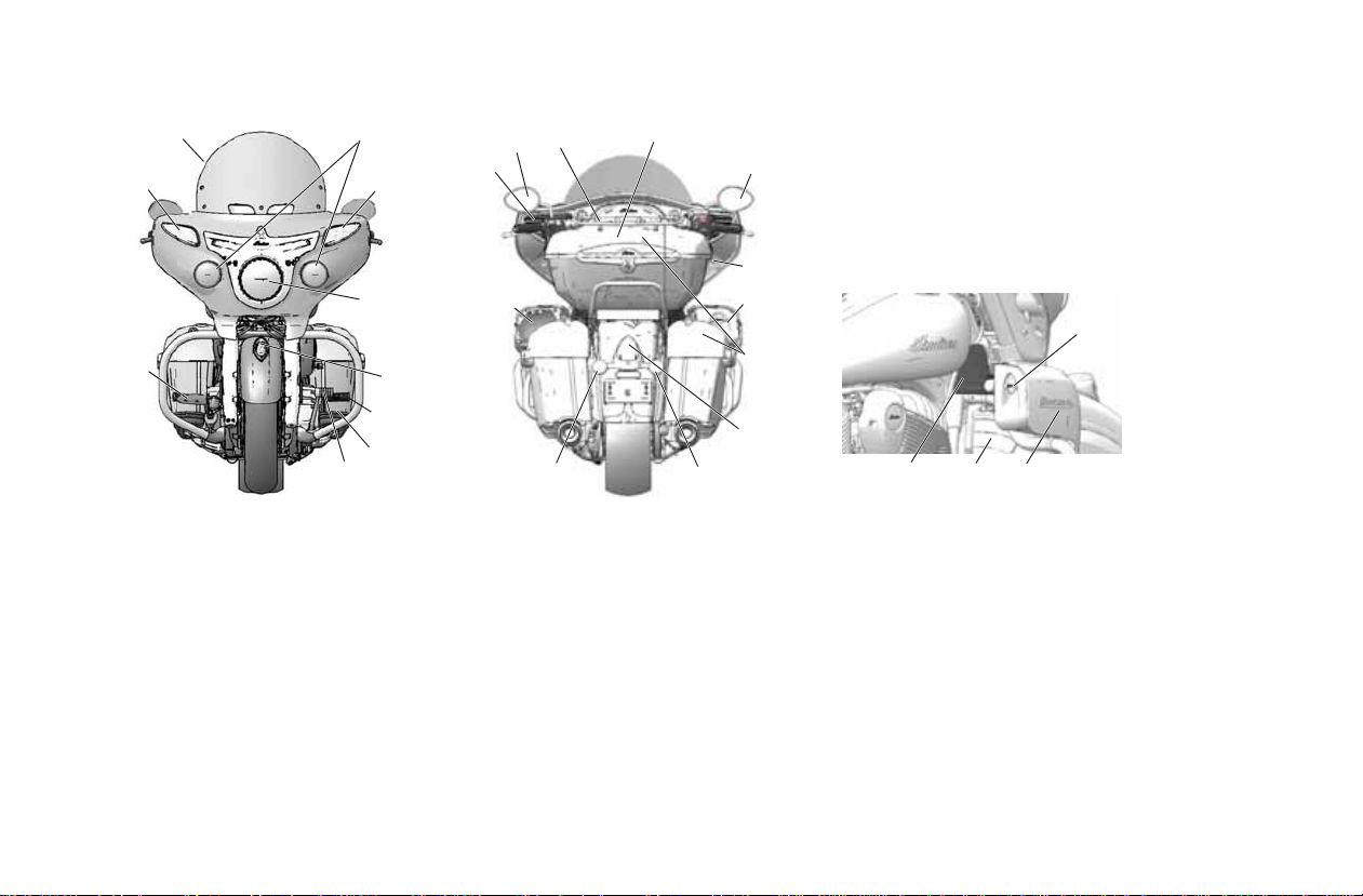
Component Identification
CHIEFTAIN shown
4
3
1
1. Rear Brake Pedal
2. 12-Volt Outlet (in trunk and/or in right saddlebag) (if
equipped)
3. Right Front Turn Signal
4. Windshield (if equipped)
5. Auxiliary Lights (if equipped)
6. Left Fr ont Turn Signal
7. Headlight
8. INDIAN MOTORCYCLE War Bonnet
9. Passenger’s Foot Peg/Floorboard (if equipped)
10. Driver’s Footrest
11. Gear Shifter
11
5
6
7
8
9
10
ROADMASTER shown
14
13
12
20
15
16
14
17
12
2
18
22
19
12. Glove Box Storage (if equipped)
13. Speakers
14. Mirror
15. Trunk Cargo Rack (if equipped)
16. Trunk (if equipped)
17. USB Cord
18. Taillight
19. Right Rear Turn Signal
20. Left Rear Turn Signal
21. Lower Fairing Wind Deflector (if equipped)
22. Lower Fairing Vent (if equipped)
23. Lower Fairing (if equipped)
21
12
23
22
Page 25

Component Identification
6
5
24
8
11
37
24. Front Fork
25. Fuel Tank
26. Air Box Cover (left)
27. Driver’s Seat
28. Battery (under seat)
29. Passenger Seat (if equipped)
30. Saddlebag (if equipped)
31. Radio Antenna (if equipped)
25
10
26
35
4
CHIEFTAIN shown
34
29
30
31
8
32. Side Cover (Left)
33. Shock Air Fill (under cover)
34. Muffler
35. Sidestand
36. Rear Tipover Bar (if equipped)
37. Front Tipover Bar (if equipped)
32
28
33
27
9
6
5
24
11
37
(CHIEFTAIN/ROADMASTER)
10
25
35
26
ROADMASTER shown
32
28
27
9
36
29
33
34
30
16
31
23
Page 26

Instruments, Features and Controls
Flasher (Hazard)
Switch
High/Low
Light Switch
Horn
Switch
Turn Signal
Switch
Engine
Starter
Switch
Engine
Stop/Run
Switch
LEFT-TOGGLE Switch
Audio Control Switches
(if equipped)
Cruise
Control
Switch
Cruise
On/Off
Switch
Left Control
Left Control
Right Control
Right Control
RIGHT-TOGGLE Switch
(active on CHIEFTAIN and ROADMASTER)
Windshield
Switches
(if equipped)
Switches
24
Page 27

Instruments, Features and Controls
Power Switch
Auxiliary
Light Switch
(if equipped)
Saddlebag/Trunk
Lock Switch
CHIEF/DARK HORSE CHIEFTAIN/ROADMASTER
Power Switch
Auxiliary
Light Switch
Hand Grip
Heater Switch
Switches
25
Page 28

Instruments, Features and Controls
Switches
Symbol Switch Description
Emergency Flasher
Switch (Hazard
Switch)
High/Low Headlight
Beam Switch
The hazard switch activates and cancels the emergency flashers. See page 27.
The high/low headlight beam switch toggles the headlight between high beam and low beam. See page
29.
-- Auxiliary Light
Switch (if equipped)
Horn Switch Press the horn switch to sound the horn.
Turn Signal Switch Move the switch to the left to activate the left turn signals. Move the switch to the right to activate the right
Stop/Run Switch Press the bo ttom of the switch (RUN) to allow the engine to start and run. Press the top of the switch (ST OP)
Starter Switch Use the starter switch to start the engine. The engine stop/run switch must be in the RUN position. See
Power Switch The power switch is located above the instrument gauge. Press an d release the power switch to enab le or
-- Saddlebag/Trunk
Lock Switch (if
equipped)
-- Heated Grip Switch Use the hand grip heater switch to turn the grip heaters on or off and to adjust the heat level. See page 30.
Press the auxiliary light switch to turn the auxiliary lights off or on. See page 29.
turn signals. A signal will deactivate automatically when speed or distance reach predetermined levels.
To cancel a signal manually , move the switch to the center position and push it inward.
Momentary Feature: Move the turn signal switch left or right and hold it in that position for a t least one second.
The momentary feature will activate and the signal will then cancel when the switch is released.
to stop the engine. See page 27.
page 28.
disable all electrical power to the v ehicle. See page 27.
Press the lock switch to lock or unlock the saddlebags and trunk (if equipped). The key fob can also be
used to lock or unlock the saddlebags and trunk.
26
Page 29

Switches
Run
Stop
Right Control
Power Switch
The pow er switch is located on the center co nsole. Press and
release the power switch to enable or disable all electrical
power to the vehicle. The power switch does not have to be
on to start the engine. See page 28.
To disable all electrical power if the motorcycle is moving
and the engine is running, press and hold the power switch
for more than three (3) seconds.
Tip: To save battery power, the vehicle will power off after five
minutes of inactivity.
Hazard Switch
The power switch must be ON to activate the flashers, but
once activated, the flashers will continue to flash when the
power switch is turned off. When the flashers are active, all
four turn signals flash.
• Press the switch to activate the flashers.
• Press the switch again to cancel the flashers.
Instruments, Features and Controls
Engine Stop/Run Switch
Use the engine stop/run switch
to turn the engine off quickly.
• Press the top of the switch
(STOP) to interrupt the
circuits and stop the engine.
The engine should not start or
run when the switch is in the
STOP position.
• Press the bottom of the switch
(RUN) to complete the circuits
and allow the engine to start
and run.
Tip: The headlights and any
accessories plugged into
power ports will remain on
until the power switch is turned
off.
27
Page 30

Instruments, Features and Controls
Starter Switch
Right Control
Switches
Engine Starter Switch
Read the engine starting
procedures before starting the
engine. See page 79.
The power switch does not have
to be on to start the engine.
Press and hold the starter switch
to engage the one-touch starting
feature, which activates the
electrical system and starts the
engine. The engine stop/run
switch must be in the RUN
position and the transmission
must be in neutral.
Keyless Ignition
When the electrical system is activated with either the
power switch or the star ter switch, the key fob must be
within range. If the k ey fob is not detected, the security light
and/or power switch will flash. The electrical system will
automatically shut down.
The starter motor will not engage during this time. If a key
fob is not available, your personal identification number
(PIN) can be entered using the turn signal switches to
unlock the security system. See page 126.
Audio System Switches (if equipped)
See page 165 for audio systems operation.
Cruise Control Switches
Refer to the Cruise Control section of this manual
(beginning on page 85) for cruise control operation.
28
Page 31

Switches
Auxiliary Light Switch
(CHIEFTAIN/ROADMASTER)
Auxiliary Light Switch
(CHIEF VINTAGE/DARK
HORSE)
High/Low Headlight Beam Switch
The headlights automatically come on when the engine is
started. See page 54.
The high/low headlight beam switch toggles the headlight
between high beam and low beam. To activate the high
beam, press the upper portion of the switch. To activate the
low beam, press the lower portion of the switch.
Instruments, Features and Controls
Auxiliary Light Switch (if equipped)
The auxiliary lights provide
additional lighting on each
side of the headlight. Some
drivers prefer using the
auxiliary lights when operating
in foggy conditions or when
passing a vehicle to help
improve visibility to other
motorists.
Press the auxiliary light switch
to turn the auxiliary lights on or
off. The switch background
light changes color to indicate
whether lights are on or off.
OFF: Red Light
ON: Green Light
The auxiliary lights turn off
when the power switch is
turned off. The auxiliary lights
automatically turn on when the
engine starts if they were on
when the engine was shut
down.
The switch background light
flashes if a fault exists with
either auxiliary light.
29
Page 32

Instruments, Features and Controls
LEFT-TOGGLE
Left Control Right Control
RIGHT-TOGGLE
(active for CHIEFTAIN and ROADMASTER)
INCREASE
OFF
DECREASE
Switches
Toggle Switches
All models are equipped with toggle switches on the front
side of the left and right handlebar controls. The LEFTTOGGLE switch is activ e for all models. The RIGHT-TOGGLE
switch is active only for CHIEFTAIN and ROADMASTER
models.
The power switch must be ON. Use the switches to toggle
through the modes of the multi-function display and to
change settings in the display.
Hand Grip Heater Switch (if equipped)
Press the top or bottom of the switch to turn the hand grip
heaters on. The center of the switch illuminates when
heaters are on. Press the center of the switch to turn the
heaters off.
The heaters have 10 heat levels, ranging from OFF (level 0)
to highest heat (level 10). Press and release the top of the
switch to increase the heat lev el b y one incr ement. Pr ess and
release the bottom of the switch to decrease heat by one
increment.
The heaters turn off when the engine is turned off. When the
engine is restarted the heaters turn on at the previous heat
level setting.
If the center of the switch flashes, the heaters may not be
working properly. Please see your dealer.
30
Page 33

Switches
Passenger’s
Switch (if
equipped)
Seat Heater Switches
Driver’s
Switch
Saddlebag/Trunk Lock Switch (if equipped)
Use the key fob or the lock switch
on the console to lock and unlock
the electric saddlebag and trunk
locks. When using the console
lock switch, the key fob must be
within range. If the key fob is not
detected, the security light and/
or power switch will flash. The
system will not perform the lock
or unlock command.
Unlock
Key Fob
Lock
Instruments, Features and Controls
Seat Heater Switches
The seat heater toggle
switches are located on
the lower left edge of the
seat.
Toggle
Position
Up HIGH
Down LOW
Center OFF
Heat
Setting
31
Page 34

Instruments, Features and Controls
Instrument Cluster (CHIEF/DARK HORSE)
The instrument cluster includes the speedometer, indicator
lamps and Multi-Function Display (MFD).
Speedometer
Indicator Lamps
MFD
Speedometer
The speedometer displays forward vehicle speed in either
miles per hour or kilometers per hour.
32
Page 35

Instruments, Features and Controls
Instrument Cluster (CHIEF/DARK HORSE)
Indicator Lamps
Lamp Indicates Condition
Chassis Fault The alert symbol illuminates if a chassis fault occurs.
Tire Pressure Monitoring
System (TPMS)
Neutral The transmission is in neutral.
High Beam The headlight switch is set to high beam. This indicator will flash if there is a problem with the low or
Turn Signal The turn signal indicator flashes when the left, right, or both turn signals (hazard) are active. If there is
Check Engine If this lamp illuminates while the engine is running, see your dealer promptly. The light will remain on if
Anti-Lock Brakes Not
Activated
Vehicle
Speed
If equipped, the TPMS indicator illuminates if low tire pressure is detected. It will also illuminate along
with the Low Battery Voltage indicator when TPMS battery power is low, requiring service.
high beam light.
a problem in the signal system, the lamps will flash at twice the normal rate.
the tilt sensor shuts down the engine. If ab normal sensor or engine operation is detected the light will
remain on as long as the fault condition exists. Retrieve the error codes for diagnosis. See page 37.
The indicator remains on until the anti-lock system activates, which occurs when vehicle speed
exceeds 6 MPH (10 km/h). When the lamp is illuminated, the anti-lock brakes will not activate, but the
conventional brake system will continue to operate normally.
When standard mode is selected, speed displays in miles per hour.
When metric mode is selected, speed displays in kilometers per hour.
33
Page 36

Instruments, Features and Controls
88
:
88
Fuel Gauge Display
Instrument Cluster (CHIEF/DARK HORSE)
Multi-Function Display (MFD)
MFD Indicators
Lamp Indicates Condition
Cruise
Control
Status
Low Oil
Pressure
Security
System
Locked
Amber Lamp: Cruise control is enabled, but
not set. When flashing, a cruise contr ol
related fault exists. Green Lamp: Cruise
control is set to the desired speed. Read the
safety and operation procedures before using
cruise control. See page 85.
This lamp illuminates when oil pressure
drops below a safe operating pressure while
the engine is running. If this lamp illuminates
while the engine is running abo ve idle speed ,
turn the engine off as soon as safely possible
and check the oil level. If the oil level is
correct and the lamp remains on after the
engine is restarted, turn the engine off
immediately. See your dealer.
This indicator lamp illuminates while the
security system is searching for the key fob
signal and when the security system is
locked. The lamp flashes if the key fob is not
detected within range or if the fob is not
program med proper ly. It also illuminates with
the low battery voltage indicator when the
key fob battery is low.
Lamp Indicates Condition
Low
Battery
Voltage
This lamp illuminates when battery voltage is
low. Turn non-essential accessories off to
conserve power. Make sure the charging
system is operating properly. See page 131.
This lamp also illuminates with the security
light and/or power switch when the key fob
battery is low, and with the TPMS lamp when
the TPMS sensor battery is low.
Fuel Gauge Display (CHIEF CLASSIC/DARK HORSE)
The segments of the fuel
gauge sho w the le v el of fuel
in the fuel tank. When the
last segment clears, a low
fuel warning is activated.
All segments including the
fuel icon will flash. Refuel
promptly.
km
mi
FE
34
Page 37

Instrument Cluster (CHIEF/DARK HORSE)
LEFT-TOGGLE
Clutch Lever
Multi-Function Display (MFD)
The power switch
must be ON to
access the MFD. Use
the mode switches to
toggle through the
modes of the multifunction display and
to change settings in
the display.
Modes Available
Odometer Engine Speed
Trip Odometer 1 Average Fuel Economy
Trip Odometer 2 DC Voltage
Clock Ambient Air Temperature
Gear Indicator Fuel Range
Odometer
The odometer displays total distance traveled.
Trip Odometers
The trip odometers (Trip 1 and Trip 2) display total distance
traveled since being reset. To reset a trip odometer, toggle
to the trip odometer, then press and hold the LEFT-TOGGLE
switch until the trip odometer resets to zero.
Instruments, Features and Controls
Engine Speed
Engine speed displays in revolutions per minute (RPM).
DC Voltage
The volt meter displays battery voltage. If the engine is not
running, approximate battery voltage displays. If the engine
is running, approximate charging voltage displa ys.
Gear Position
Gear position displays at all times while the engine is
running, unless a fault occurs with the gear position sensor.
Temperature
The temperature area displays ambient air temperature.
Fuel Range
The fuel range displays the distance the motorcycle can
travel on the remaining fuel in the fuel tank.
Average Fuel Economy
Average Fuel Economy displa ys as of the last time the mode
was reset. To reset, press and hold LEFT-TOGGLE while
viewing the fuel economy display.
Heated Grips Heat Level Setting (if equipped)
The heated grips heat level displays if the heat level is
above zero.
35
Page 38

Instruments, Features and Controls
Instrument Cluster (CHIEF/DARK HORSE)
Multi-Function Display (MFD)
Display Units (Standard/Metric)
The display can be changed to display either standard or
metric units of measurement.
Standard
Display
Distance Miles Kilometers
Fuel U.S. Gallons I = Imperial
Temperature Fahrenheit Celsius
Time 12-Hour Clock 24-Hour Clock
1. Stop the engine.
2. Wait 10 seconds.
3. Press and hold the LEFT-TOGGLE switch while pressing
the power switch.
4. When the display flashes the distance setting, tap the
LEFT-TOGGLE switch to advance to the desired setting.
5. Press and hold the LEFT-TOGGLE switch to save the
setting and advance to the next display option.
6. Repeat the procedure to change remaining display
settings.
Metric Display
Liter = Liters
Gallons
Clock
Tip: The clock must be reset any time the battery has been
disconnected or discharged.
1. Use the LEFT-TOGGLE switch to toggle to the odometer
display.
2. Press and hold the LEFT-TOGGLE switch until the hour
segment flashes. Release the switch.
3. With the segment flashing, tap the LEFT-TOGGLE switch
to advance to the desired setting.
4. Press and hold the LEFT-TOGGLE switch until the next
segment flashes. Release the switch.
5. Repeat steps 3-4 twice to set the 10-minute and 1-minute
segments. After completing the 1-minute segment, step
4 will save the new settings and exit the clock mode.
36
Page 39

Instruments, Features and Controls
Instrument Cluster (CHIEF/DARK HORSE)
Multi-Function Display (MFD)
Diagnostic Functionality
Certain conditions will cause an error message to display in the screen. If this occurs, please see your authorized dealer.
Message Location Indicates
ERROR All Checksum error (gauge malfunction)
LO (CHIEF) DC Voltage Screen Voltage remai ns below 11.0 volts for more than 10 seco nds
OV (CHIEF) DC Voltage Screen Voltage remains above 15.0 volts for more than 10 seconds
Engine Error Codes
The error scre en displays only when the CHECK ENGINE light is on or when it
goes on and off during one ignition cycle. Error codes display only during the
current ignition cycle. When the power switch is turned OFF, the code and
message is lost, but will reappear if the fault reoccurs after restarting the
engine.
If the CHECK ENGINE indicator lamp illuminates, retrieve the error codes
from the displa y.
1. If the error codes are not displayed, use the LEFT-TOGGLE switch to
toggle until “Ck ENG” displays on the main line of the display.
2. Press and hold the LEFT-TOGGLE switch to enter the diagnostics code
menu.
3. Record the three numbers displayed in the gear position, clock and
odometer displays.
4. See an authorized dealer for code details and diagnosis.
Error Code
Number (0-9)
Failure Mode Indicator (FMI)
Suspect Parameter
Number (SPN)
37
Page 40

Instruments, Features and Controls
Instrument Cluster (CHIEF/DARK HORSE)
Multi-Function Display (MFD)
Low Oil Pressure Display (CHIEF)
“LO OIL” displays under the following conditions.
Condition Indicates Action Required
Engine oil pressure
has dropped while the
engine is running.
Oil pressure is below a
safe operating pressure.
Stop the engine as soon as safely possible
and check the oil level. If the oil level is
sufficient, but “LO OIL” continues to display
after restarting the engine, stop the engine
immediately.
38
Page 41

Instruments, Features and Controls
Instrument Cluster (CHIEFTAIN/ROADMASTER)
The instrument cluster includes the speedometer,
tachometer , fuel gauge, indicator lamps and multi-function
display (MFD).
Speedometer
The speedometer displays forward vehicle speed in either
miles per hour or kilometers per hour.
Speedometer
Multi-Function Display
Indicator Lamps
Tachometer
Fuel Gauge
Tachometer
The tachometer displays engine speed in revolutions per
minute (RPM). A red line on the face of the gauge indicates
the maximum safe engine speed.
Excessive engine speed can cause engine damage or
failure, which could result in serious injury or death. Do not
allow engine speed to exceed the red line.
Fuel Gauge
The fuel gauge displays fuel level. For the most accurate
reading, sit on the motorcycle and bring it to the upright
position.
39
Page 42

Instruments, Features and Controls
Instrument Cluster (CHIEFTAIN/ROADMASTER)
Indicator Lamps
Lamp Indicates Condition
Neutral The transmission is in neutral and the power switch is ON.
40
Vehicle
Speed
High Beam The headlight switch is set to high beam. This indicator will flash if there is a pr oblem with the low or high beam
Low Oil
Pressure
Low Fuel This lamp illuminates when approximately one gallon (3.8 liters) of fuel remains in the fuel tank. The LCD
Turn Signal One arrow flashes when the corresponding turn signal is activated. Both arrows flash when the hazard signal is
When standard mode is selected, speed displays in miles per hour.
When metric mode is selected, speed displays in kilometers per hour.
light.
This lamp illuminates when oil pressure drops below a safe operating pressure while the engine is running. If
this lamp illuminates while the engine is running above idle speed, turn the engine off as soon as safely
possible and check the oil level. If the oil level is correct and the lamp remains on after the engine is restarted,
turn the engine off immediately. See your dealer.
Display will switch into a Low Fuel Mileage Counter Mode to provide the rider with mileage tracking from the
time the indicator was activated.
activated. If there is a problem in the signal system, the lamps will flash a t twice the normal rate.
Page 43

Instruments, Features and Controls
Instrument Cluster (CHIEFTAIN/ROADMASTER)
Indicator Lamps
Lamp Indicates Condition
Low Battery
Voltage
Cruise Control
Status
ABS Not
Activated
Check Engine This lamp illuminates briefly when the power switch is turned ON. This indicates proper function. If this lamp
Tire Pressure
Monitoring
System (TPMS)
Security System
Locked
This lamp illuminates when battery voltage is low. Turn non-essential accessories off to conserve power. Make
sure the charging system is operating proper ly. See page 131. This lamp also illuminates with the security light
and/or power switch when the key fob battery is low, and with the TPMS lamp when the TPMS sensor battery is
low.
Amber Lamp: Cruise control is enabled, but not set. When flashing, a cruise control related fault exists. Green
Lamp: Cruise control is set to the desired speed. Read the safety and operation procedures before using cruise
control. See page 85.
The indicator remains on until the anti-lock system activates, which occurs when veh icle spe ed e xcee ds 6 MPH
(10 km/h). When the lamp is illuminated, the anti-lock brakes will not activate, but the conventional brake
system will continue to operate normally.
illuminates while the engine is running, see an authorized dealer promptly. The light will remain on if the tilt
sensor shuts down the engine. If abnormal sensor or engine operation is detected the light will remain on as
long as the fault condition exists. Retrieve the error codes for diagnosis. See page 46.
The TPMS indicator illuminates if low tire pressure is detected. It will also illuminate along with the Low Battery
Voltage indicator when TPMS battery power is low, requiring service.
This indicator lamp illuminates while the security system is searching for the key fob signal and when the
security system is locked. The lamp flashes if the key fob is not detected within range or if the fob is not
programmed p roperly. It also illuminates with the low battery voltage indicator when the key fob battery is low.
41
Page 44

Instruments, Features and Controls
LEFT-TOGGLE
Left Control Right Control
RIGHT-TOGGLE
Instrument Cluster (CHIEFTAIN/ROADMASTER)
Multi-Function Display (MFD)
The powe r switc h must be on or the e ngine must be running
to view or change settings in the MFD. Use the LEFTTOGGLE and RIGHT-TOGGLE switches to toggle through
the modes of the multi-function display and to change
settings in the display. See page 30.
Infotainment Display Settings
There are four zones in the
center display.
ZONE ONE (1) provides the
time and outside air
temperatur e. While the units for
time and temperature can be
changed, these items cannot be
adjusted by the rider.
ZONE TWO (2) will always
display audio system
information.
ZONES THREE (3) and FOUR (4)
will display vehicle/engine
information.
Tip: Zone three can be set to
display expanded audio
information. See page 45.
You can modify the items in zone four by changing the
settings in the SET BOTTOM SCREEN menu. See page 51.
(1)
(2)
(3)
(4)
42
Page 45

Instruments, Features and Controls
Instrument Cluster (CHIEFTAIN/ROADMASTER)
Infotainment Display Settings
The following items can be displayed in Zone Three on the
infotainment display:
• Trip 1 Hours/Distance
• Trip 2 Hours/Distance
• Fuel Economy
• Front/Rear Tire Pressure
• Engine Hours/Oil Lif e
•Average Speed & Battery Voltage
• Expanded Radio Information
• Heated Grip Power Level (if equipped)
• Diagnostic Trouble Codes (DTCs)
Press LEFT-TOGGLE repeatedly to cycle through the Zone
Three displays.
Trip 1 Hours/Distance
Trip 1 Hours/Distance will display the
total hours and distance in miles or
kilometers.
1. Press and hold
reset Trip 1 hours and distance to
zero.
2. Press
the Trip 2 display.
Trip 2 Hours/Distance
Trip 2 Hours/Distance will display the
total hours and distance in miles or
kilometers.
1. Press and hold
reset Trip 2 hours and distance to
zero.
2. Press
Fuel Economy display.
LEFT-TOGGLE to
LEFT-TOGGLE to cycle to
LEFT-TOGGLE to
LEFT-TOGGLE to cycle to
43
Page 46

Instruments, Features and Controls
Instrument Cluster (CHIEFTAIN/ROADMASTER)
Infotainment Display Settings
Fuel Economy
This screen will display the current
instant and average miles per gallon
(MPG) or liters per 100 kilometers.
1. Press and hold
reset the average.
2. Press
Front/Rear Tire Pressure
This screen will display the current
front and rear tire pressure in PSI or
kPa.
• Press
Engine Hours/Oil Life display.
LEFT-TOGGLE to cycle to
the Front/Rear Tire Pressure
display.
LEFT-TOGGLE to cycle to the
LEFT-TOGGLE to
Engine Hours/Oil Life
This screen will display the total
engine hours accumulated when the
engine is running.
Engine oil life is also displayed. The
rate at which oil life is reduced to 0% is
determined by the following:
• Engine break-in period: 0-500 miles or
804 km
• Routine oil change interv als: Every 5,000
miles or 8,046 km
Tip: When engine oil life reaches 0%,
change the engine oil and filter.
After changing the engine oil and
filter:
1. Press and hold
flash.
2. Press and hold
to 100%.
3. Press
Voltage screen.
LEFT-TOGGLE until the value begins to
LEFT-TOGGLE to reset the engine oil life
LEFT-TOGGLE to display Average Speed/Battery
44
Page 47

Instruments, Features and Controls
Instrument Cluster (CHIEFTAIN/ROADMASTER)
Infotainment Display Settings
Average Speed/Battery Voltage
This screen displays the average
motorcycle speed an d curr ent battery
voltage.
1. Press and hold
reset the average speed.
2. Press
Expanded Audio Information
In this mode, the display screen will
dedicate zone three to the audio
system and allow for up to six lines of
audio system information.
Press
• Heated Grips (if equipped)
• Diagnostic Trouble Codes (if present)
•Trip 1 (top of menu)
LEFT-TOGGLE to cycle to
Expanded Audio Information.
LEFT-TOGGLE to cycle to:
LEFT-TOGGLE to
Heated Grips (if equipped)
This screen displays the heated grip
heat level setting. The screen does not
display if heaters ar e set at z e ro or if
heated grips are not installed.
Press
LEFT-TOGGLE to cycle to:
• Diagnostic Trouble Codes (if present)
•Trip 1 (top of menu)
45
Page 48

Instruments, Features and Controls
Instrument Cluster (CHIEFTAIN/ROADMASTER)
Infotainment Display Settings
Diagnostic Trouble Codes (DTCs)
If the CHECK ENGINE indicator is
illuminated on the instrument cluster,
this screen will display, indicating
there are Diagnostic Trouble Codes
(DTCs).
The error screen displays only when
the CHECK ENGINE light is on and
only during the current ignition cycle.
DTCs will reappear only if the fault
reoccurs after restarting the engine.
Retrieving Error Codes
If the CHECK ENGINE indicator illuminates, you can r etriev e
the error codes from the DTC display.
1. Press and hold
enter the display screen.
Tip: The CHECK ENGINE icon will appear
on the screen when in the DTC display
mode.
2. Press LEFT-TOGGLE to cycle
through the list of available codes.
3. Record the SPN and FMI numbers.
4. See an authorized INDIAN
MOTORCYCLE dealer for code
details and diagnosis.
5. Press and hold
exit.
LEFT-TOGGLE to
LEFT-TOGGLE to
46
Page 49

Instruments, Features and Controls
Instrument Cluster (CHIEFTAIN/ROADMASTER)
Instrument Cluster Setup
The instrument cluster setup menus allow the following
actions:
• Set clock
• Set units (volume, temperature, clock
type, pressure)
• Set bottom screen display (trip 1
distance, instant fuel economy,
average fuel economy, and range)
• View instrument cluster software/
hardware information
• Set Tire Pressure Monitoring System
(TPMS) (dealer only)
• Adjust infotainment display
brightness
To access the instrument cluster setup menus:
1. Place the transmission in neutral.
2. Press and hold
LEFT-TOGGLE and RIGHT-TOGGLE
simultaneously until the SETUP menu appears on the
display.
3. Press
RIGHT-TOGGLE repeatedly to cycle through the
setup menu.
4. Press
LEFT-TOGGLE to enter the desired menu.
Setting the Clock
1. With SET CLOCK highlighted on
the setup menu, press
TOGGLE.
2. Press
to set the hours.
3. Press
tens of minutes.
4. Press
to set the tens of minutes.
5. Press
minutes.
6. Press
to set the minutes.
7. Press
EXIT.
8. Press
LEFT-
LEFT-TOGGLE repeatedly
RIGHT-TOGGLE to move to
LEFT-TOGGLE repeatedly
RIGHT-TOGGLE to move to
LEFT-TOGGLE repeatedly
RIGHT-TOGGLE to enter the time and move to
LEFT-TOGGLE to exit.
47
Page 50

Instruments, Features and Controls
Instrument Cluster (CHIEFTAIN/ROADMASTER)
Instrument Cluster Setup
Set Units
Use the SET UNITS menu to set the
following items:
• DISTANCE: Miles or kilometers
• VOLUME: Gallon, Imperial Gallon or
Liter
• TEMPERATURE: Fahrenheit or Celsius
• CLOCK TYPE: 12-hour or 24-hour
• PRESSURE: PSI or kPa
1. With SET UNITS highlighted on
the setup menu, press LEFT-
TOGGLE.
2. Press
RIGHT-TOGGLE
repeatedly to cycle through
menu items.
3. Press
LEFT-TOGGLE to enter
the desired SET UNITS menu.
Set Units - Distance Setting
Use the DISTANCE menu to chan ge
the speedometer and distance
units. Select either miles or
kilometers.
1. With DISTANCE highlighted in
the SET UNITS menu, press
LEFT-TOGGLE.
2. Press
miles or kilometers.
3. Press
desired setting.
4. Press
EXIT.
5. Press
RIGHT-TOGGLE to select
LEFT-TOGGLE to set the
RIGHT-TOGGLE to select
LEFT-TOGGLE to exit.
48
Page 51

Instruments, Features and Controls
Instrument Cluster (CHIEFTAIN/ROADMASTER)
Instrument Cluster Setup
Set Units - Volume Settings
Use the VOLUME menu to change
the instrument cluster volume
units. Select gallon, imperial gallon
or liter.
1. With VOLUME highlighted in
the SET UNITS menu, press
LEFT-TOGGLE.
2. Press
3. Press
4. Press
5. Press
RIGHT-TOGGLE to select
gallon, imperial gallon, or liter.
LEFT-TOGGLE to set the
desired setting.
RIGHT-TOGGLE to select
EXIT.
LEFT-TOGGLE to exit.
Set Units - Temperature Settings
Use the TEMPERATURE menu to
change the instrument cluster
temperature units. Select
Fahrenheit or Celsius.
1. With TEMPERATURE
highlighted in the SET UNITS
menu, press
2. Press
fahrenheit or Celsius.
3. Press
desired setting.
4. Press
EXIT.
5. Press
LEFT-TOGGLE.
RIGHT-TOGGLE to select
LEFT-TOGGLE to set the
RIGHT-TOGGLE to select
LEFT-TOGGLE to exit.
49
Page 52

Instruments, Features and Controls
Instrument Cluster (CHIEFTAIN/ROADMASTER)
Instrument Cluster Setup
Set Units - Clock Type
Use the CLOCK TYPE menu to
change the clock format. Select 12hour or 24-hour format.
1. With CLOCK TYPE highlighted
in the SET UNITS menu, press
LEFT-TOGGLE.
2. Press
3. Press
4. Press
5. Press
RIGHT-TOGGLE to select
12 hour or 24 hour.
LEFT-TOGGLE to set the
desired clock format.
RIGHT-TOGGLE to select
EXIT.
LEFT-TOGGLE to exit.
Set Units - Pressure
Use the PRESSURE menu to change
the pressure display format. Select
PSI or KPA.
1. With PRESSURE highlighted in
the SET UNITS menu, press
LEFT-TOGGLE.
2. Press
PSI or KPA.
3. Press
desired pressure display
format.
4. Press
EXIT.
5. Press
RIGHT-TOGGLE to select
LEFT-TOGGLE to set the
RIGHT-TOGGLE to select
LEFT-TOGGLE to exit.
50
Page 53

Instruments, Features and Controls
Instrument Cluster (CHIEFTAIN/ROADMASTER)
Instrument Cluster Setup
Set Bottom Screen Menu
Use the SET BOTTOM SCREEN
menu to display one of the
following items in ZONE FOUR of
the display screen:
• Trip 1 Distance
• Instant Fuel
• Average Fuel
•Range
1. With SET BOTTOM SCREEN
highlighted on the setup menu,
press
LEFT-TOGGLE.
2. Press
3. Press
4. Press
5. Press
RIGHT-TOGGLE
repeatedly to cycle through
menu items.
LEFT-TOGGLE to enter
the desired SET UNITS menu.
RIGHT-TOGGLE to select
EXIT.
LEFT-TOGGLE to exit.
Trip 1 Distance Display
Instant Fuel Display
Aver age Fuel Display
Range Display
51
Page 54

Instruments, Features and Controls
EXIT
TPMS
ERASE TPMS
SENSORS
Instrument Cluster (CHIEFTAIN/ROADMASTER)
Instrument Cluster Setup
Gauge Information
The instrument cluster hardware
and software part and serial
numbers are displayed on the
Gauge Information menu.
1. With GAUGE INFORMATION
highlighted on the setup menu,
press
LEFT-TOGGLE.
2. Press
RIGHT-TOGGLE to select
EXIT.
3. Press
LEFT-TOGGLE to exit.
Tire Pressure Monitoring System
(TPMS) Setup
Do not attempt to access the TPMS
menu. Without the pr ope r training
and tools, you may inadvertently
erase the sensor iden t ification
numbers from system memory,
which would disable the TPMS.
The TPMS setup menu allows your
authorized INDIAN MOTORCYCLE
dealer to register new tire pressure
sensors and to relearn erased
sensors using the TPMS tool.
LEARN TPMS
SENSORS
52
Page 55

Instruments, Features and Controls
Instrument Cluster (CHIEFTAIN/ROADMASTER)
Instrument Cluster Setup
Set Brightness
The brightness level of the instrument cluster and di splay
screen can be adjusted . There are two methods to enter the
Set Brightness menu.
METHOD 1:
This method bypasses the
instrument cluster setup menu. The
transmission does not have to be in
neutral using this method.
1. Press and hold
TOGGLE until the SET
BRIGHTNESS menu appears.
2. Press
3. The menu will close after the
RIGHT-TOGGLE
repeatedly to adjust the
instrument cluster brightness.
desired brightness level is set.
RIGHT-
METHOD 2:
1. With SET BRIGHTNESS
highlighted on the setup menu,
press
2. Press
repeatedly to adjust the
brightness level from 0% to
100%.
3. When the desired brightness
level is set, press
TOGGLE to select EXIT.
4. Press
LEFT-TOGGLE.
LEFT-TOGGLE
RIGHT-
LEFT-TOGGLE to exit.
53
Page 56

Instruments, Features and Controls
Increase
Speed
Decrease
Speed
Headlights
The headlights automatically come on when the engine is
started.
WARNING! Motorcycle riders must remain as visible as possible a t
all times. To aid in this, the headlight must be on at all times. Do not
modify the ignition/headlight wiring to circumvent the automatic
headlight feature.
The headlights operate only when the engine is running.
You can use the high/lo w headl ight beam swi tch to override
this function and allow the headlights to operate when the
engine is not running. Turn the pow er switch on, then toggle
the high/low headlight beam switch to turn the headlights
on.
Throttle Control Grip
The throttle control grip is
located on the right handlebar.
Use the throttle control grip to
control engine speed.
While seated in the proper
riding position:
• Roll the grip rearward to
open the throttle (increase
engine speed and power).
• Roll the grip forward to close the throttle (decrease
engine speed and power).
The control grip is spring loaded. When you release the
grip, the throttle return s to the idle position.
Clutch Lever
The clutch lever is
located on the left
handlebar . Disengage the
clutch before shifting
gears. For smooth clutch
operation, pull the lever
quickly and r elease it in a
brisk but controlled
manner.
• To disengage the clutch, pull the lever toward the
handlebar.
• To engage the clutch, release the lever in a brisk but
controlled manner.
Clutch Lever
54
Page 57

Gear Shift Lever
The gear shift lever is located on the left side of the
motorcycle. Operate the lever with your foot.
• Press downward on the toe lever to shift to a lower gear.
• Lift upward on the toe lever to shift to a higher gear.
• Release the lever after each gear shift.
• See pages 81-83 for gear shifting procedures.
6
5
4
3
2
N
1
Instruments, Features and Controls
Tire Pressure Monitoring System
(TPMS) (if equipped)
NOTICE: On models equipped with a TPMS, the sensors are located
180° from the valve stem. Use caution w hen servicing tires.
To avoid damaging a sensor , break the bead at the valve
stem, then at 90° and 270° from the valve stem as requir ed.
With a TPMS, the pressure of each tire can be viewed in the
MFD. If dashes display instead of a pressure value while
traveling above 15 MPH (24 km/h), the system may not be
functioning properly. See your dealer for service.
The TPMS warning indicator will illuminate if low tire
pressure is detected. Always correct low tire pressure
promptly. Always inspect tire pressure and condition before
each ride. See page 70.
The TPMS display may indicate an incr ease in tire pressure
while riding, a normal occurrence as tires warm up. Riding
into colder conditions may result in a dr op in tir e pressure as
tires cool down. Regardless of conditions, low tire pressures
should always be corrected promptly.
55
Page 58

Instruments, Features and Controls
Step 1
Shelf
Plug
Step 3
Step 5
Trunk (if equipped)
Do not exceed the cargo capacity of a trunk, a cargo rack or
a trunk/cargo rack combination. The capacity for the trunk
alone, as well as for any trunk/cargo r ack combination, is 30
lbs. (10 kg). The capacity for a rack alone is 5 lbs. (2.2 kg). If
you load a rack with 5 lbs. (2.2 kg) of cargo, do not add more
than 25 lbs. (11.3 kg) to the trunk.
Trunk Removal/Installation
1. Working from below
the trunk, reach up
onto the shelf to access
the harness plug. Slide
the plug upward and
forward to remove it
from the she lf.
2. Depress the release
tab to disconnect the
plug.
3. Place a shop towel on
the fender to prevent
scratches, then r emov e
the harness from the
plastic harness
support and place the
harness on the towel.
4. Open the saddlebag lids.
5. Make sure the anti-theft
latches are in the up
(released) position.
Tip: Locking bolts (if installed)
must be removed to access
the latches. This would also
require removing
saddlebags.
6. From the r ear of the motor cycle , gr asp the trunk bumper
firmly with both hands. Pull the trunk assembly upward
to disengage the trunk support legs from the saddlebag
support bracket bushings. Pull upward and rearward to
remove the trunk from the bike.
7. Place the trunk in a safe location to prevent damage.
8. Loop the harness and place
the wires into the fabric
pocket under the rear seat
flap. Place the connector in
the connector storage area
under the rear seat flap.
Lower the flap.
Harness Storage
56
Page 59

Saddlebags (if equipped)
Electrical Connection
Quick-Release Latch
Bushing
Latch Pin
Spool
Do not exceed the weight limit of each saddlebag. Always
distribute weight evenly in each of the saddlebags. Refer to
the saddlebag/cargo warning label on or near the
saddlebag for cargo capacity.
Hard bag capacity is 22 lbs. (10 kg) of cargo per side.
Soft bag capacity is 15 lbs. (6.8 kg) of cargo per side.
Hard Bag Removal
1. Unlock the electric saddlebag
locks (if equipped).
Tip: The provided key can also be
used in the latch release buttons
to unlock the saddlebag lids.
2. Remove the side cover.
3. Disconnect the saddlebag
lock wiring near the seat.
4. Press the lid latch release
button and lift the lid.
5. Flip the two quick-release
latches upward.
Instruments, Features and Controls
6. Tilt the saddlebag away from the frame of the vehicle to
remove it.
7. To reinstall, place the hard bag in a fully seated position
on the muffler.
NOTICE: To prevent damage to components, alwa ys make sure
saddlebags are fully seated onto the muffler before
engaging the latches.
8. Make sure the rubber bushings on the latch pins are
fully engaged in the spools. Engage the quick-release
latches and flip them fully downward.
9. Reconnect the electrical wiring.
10. Reinstall the side cover, using care to avoid damaging
electrical wires.
57
Page 60

Instruments, Features and Controls
Saddlebags
Soft Bag Removal
1. Unbuckle the saddlebag
lid clasps and open the lid.
2. Flip the two quick-release
latches upward.
3. Tilt the saddlebag away
from the fender and lift
upward to remove it from
the spools.
WARNING! Improper saddlebag
installation can result in loss of
control, accident and driving
hazards for other motorists (if
saddlebag falls from the
motorcycle). Always make sure
saddlebag mounting brackets are
fully seated onto the spools before engaging latches.
4. To reinstall, place the soft bag in position. Make sur e the
mounting bracket is seated fully on the spool. Mak e sure
the rubber bushings on the latch pins are fully engaged
in the spools.
5. Engage the quick-release latches and flip them fully
downward.
Mounting Bracket
Spool
Latches
Sidestand
The sidestand is equipped with a safety switch that prevents
operation of the motorcycle if the sidestand is deployed.
WARNING! An improperly r etracted sidestand could contact the
ground and cause a loss of control resulting in serious injury or
death. Always retract the sidestand fully before operating the
motorcycle.
To park the motorcycle, swing the end of the sidestand
downward and away from the motorcycle until it is fully
extended. Always turn the handlebars to the left for
maximum stability. Lean the motorcycle to the left until the
sidestand firmly supports the motorcycle.
CAUTION! If the motorcycle weight is not r esting on the sidestand,
it will not lock. In this situation, any movement of the motorcycle
could cause the sidestand to retract slightly. If the sidestand is not in
the full forward position when the motorcycle weight is rested on it,
the motorcycle could fall over, possibly causing injury and damage to
the motorcycle.
To retract the sidestand, straddle the motorcycle and bring
it to the fully upright position. Swing the end of the sidestand
upward and toward the motorcycle until it is fully retracted.
Mirrors
Your vehicle is equipped with convex mirrors. Objects seen
in a mirror may be closer than they appear. Always adjust
mirrors before riding.
To adjust the mirr ors, sit on the motorcycle in the anticipated
riding position. Adjust the mirrors so that you can see a
small portion of your shoulders in each mirror.
58
Page 61

Windshield (if equipped)
Windshield Removal
Applies to: CHIEF
1. If equipped with a
quick-latch windshield,
rotate the two latches
upward.
2. From the front of the
motorcycle , pull firmly
on the upper
windshield to remove
the windshield from the
upper mounts, then pull
the windshield upward
and away from
motorcycle.
3. Reverse this procedure
to reinstall the
windshield. Rotate the
latches fully downward
to secure the
windshield.
WARNING! Improper windshield installation can result in loss of
control, accident and driving hazards for other motorists (if
windshield falls from the motorcycle). Always make sure the
windshield is fully seated before engaging latches.
Latches
Instruments, Features and Controls
Windshield Adjustment
Applies to: CHIEFTAIN/ROADMASTER
Use the windshield switch to adjust windshield
height for the best wind deflection.
• Press the top of the switch to adjust th e
windshield upward.
• Press the bottom of the switch to adjust the
windshield downward.
Windshield Care
NOTICE: Brake fluid and alcohol will permanently damage the
windshield and some types of thread-locking agents. Do
not use glass cleaners, water or soil r epellents, and
petroleum or alcohol based cleaners on the windshield, as
these products can dama ge the windshield.
The windshield provides wind protection and increased
riding comfort but will not protect riders in a collision with
another vehicle, the road, birds or any other object. Do not
ride with a loose or damaged windshield or mounting
hardware. Regularly check all fasteners for tightness.
Clean the windshield with a soft cloth and plenty of warm
water. Dry with a soft clean cloth. Remove minor scratches
with a high-quality polishing compound designed for use on
polycarbonate surfaces.
59
Page 62

Instruments, Features and Controls
Brakes
Anti-Lock Brake System (ABS)
The anti-lock brake system automatically reduces or increases brake pressure as needed to provide optimum braking
control, reducing the chance of wheel lock-up during hard braking events or when braking on rough, uneven, slippery or
loose surfaces. See page 10.
1. The anti-lock brake system cannot be turned off.
2. The ABS indicator always illuminates when vehicle power is turned on. It remains illuminated until the anti-lock system
activates, which occurs when vehicle speed exceeds 6 MPH (10 km/h).
3. When the lamp is illuminated, the anti-lock brakes will not activate, but the conventional brake system will continue to
operate normally.
4. When the anti-lock brakes engage during a braking event, the rider will feel pulsing at the brake levers. Continue to
apply steady pressure to the brakes for the best stopping performance.
5. If the ABS light does not come on when the key is tur ned to the ON or PARK position, see your authorized INDIAN
MOTORCYLE dealer for service.
60
Page 63

Instruments, Features and Controls
Brakes
Anti-Lock Brake System (ABS)
• If the lamp continues to illuminate after vehicle speed exceeds 6 MPH (10 km/h), the ABS system is not functioning. See
your INDIAN MOTORCYCLE dealer promptly for service.
• Operating with non-recommended tires or improper tire pressure may reduce the effectiveness of the anti-lock brake
system. Always use the recommended size and type of tires specified for your v ehicle. Always maintain the re commended
tire pressure.
• The anti-lock brake system will not prevent wheel lockup, loss of traction or loss of control under all conditions. Always
adhere to all safe motorcycle-riding practices as recommended.
• It is not unusual to leave tire marks on the road surface during a hard braking event.
• The anti-lock brake system does not compensate for or reduce the risks associated with:
- excessive spe ed
- reduced traction on rough, uneven or loose surfaces
- poor judgment
- improper operation
61
Page 64

Instruments, Features and Controls
Pin
Hole
Wheel
Rear Brake
Pedal
Brakes
The front brake lever activates the front brake calipers. The
rear brake pedal activates the rear brake caliper. For
maximum brake effectiveness, apply the front brake lever
and the rear brake pedal together.
Front Brake Lever
The front brake lever is
located on the right
handlebar. This lever controls
only the front brak es. The front
brakes should be applied
simultaneously with the rear
brakes. To apply the front
brake, pull the lever toward
the handlebar. See page 84 for braking procedures.
Front brake lever reach (distance to the hand grip) is
adjustable.
1. Gently push and hold the lever away from the hand grip.
The adjuster wheel is located between the lever and the
switch cube.
2. To increase reach distance, rotate the adjuster to align a
lower number of hash marks with the pin.
3. To decrease the reach distance, rotate the adjuster to
4. Make sure the pin is fully seated into the selected hole.
align a higher number of hash marks with the pin.
Rear Brake Pedal
The rear brak e pedal is located
on the right side of the
motorcycle. Press downward
on the rear brake pedal to
apply the r ear brake.
WARNING! Resting your foot on
the brake pedal will cause
excessive and premature wear of
brake pads and reduced braking
efficiency, which could result in
severe injury or death.
See page 84 for braking
procedures.
62
Page 65

Passenger Floorboard Supports (if equipped)
The passenger floorboard height and angle can be
adjusted.
To adju st the an gle, loosen
both attachment screws.
Rotate the floorboard to the
desired position using the
indicator mark on the rearfacing support as a guide,
then tighten the screws.
Torque: 18 ft-lbs (24.4 Nm)
To adju st the height, remove
both attachment screws. Mo v e
the floorboard assembly to the
next hole position, then
reinstall the fasteners, adjust
the angle and tighten the fasteners.
Torque: 18 ft-lbs (24.4 Nm)
Attachment Screws
Instruments, Features and Controls
63
Page 66

Instruments, Features and Controls
Deflector
Open
Vent
Open
Deflector
Closed
Vent
Closed
Fuel Cap
The fuel filler cap is located on the right side of the console .
An ornamental cap is located on the left side of the console.
Do not attempt to remove the ornamen tal ca p.
Lower Fairing Deflectors/Vents
If equipped, open the fairing vents and wind deflectors for
maximum air flow and rider cooling. Close the vents and
deflectors for maximum protection from wind, rain and cold
air flow.
Ornamental Cap
(Do not remove)
DARK HORSE shown
1. Turn the fuel cap counter-clockwise to remove it.
2. See page 78 for fueling instructions.
3. To tighten the cap, turn it clockwise until the seal
compresses onto the tank, then continue to tighten until
the cap ratchets several times.
64
Fuel Cap
Page 67

To k eep your motorcycle in safe operating condition, alwa ys
perform the recommended pre-ride inspections befor e
each ride. This is especially important before making a l ong
trip and when removing the motorcycle from storage.
WARNING! Failure to perform the recommended pre-ride
inspections could result in component failure while riding, which
could result in serious injury or death. Always perform the pre-ride
inspections before each ride. When inspection reveals the need for
adjustment, replacement or repair, perform the service promptly, or
see your authorized INDIAN MOTORCYCLE dealer for service.
WARNING! Read the entire Instruments, Features and Controls
section of this manual before riding your motorcycle. A complete
understanding of the features and capabilities of your motorcycle is
essential to its safe operation. Anything less may result in serious
injury or death.
Pre-Ride Inspections
You must be familiar with all instruments and controls to
perform the pre-ride inspections.
Tip: During the pre-ride inspections you may use products that are
potentially hazardous, such as oil or brake fluid. When using
any of these products, always follow the instructions and
warnings on the product packaging.
When inspections reveal the need for adjustment,
replacement or repair:
• refer to the maintenance section of this manual (page 88)
• refer to the INDIAN MOTORCYCLE Se rvice Manual
• or see your authorized INDIAN MOTORCYCLE dealer
65
Page 68

Pre-Ride Inspections
Turn the power switch on and move the stop/run switch to RUN before performing the following electrical inspections. Turn
the pow er switch off after completing these inspections. If inspection of any electrical item reveals component failure, repair
or replace the component before operating the motorcycle.
Item Inspection Procedure
Electrical
Headlamp Move the headlight switch from low beam to high beam to turn the lights on and verify operation of both
Taillights/Brakelight Verify that the taillights and license plate light illuminate. Verify that the taillight lamps increase in
Turn Signals Move the turn signal switch to the left. Verify that front and rear left turn signals flash, as well as the
Emergency Flashers Press the hazard switch to activate the flashers. Verify that all four turn signals flash, as well as the lamps on
Horn Press the horn switch. Verify that the horn sounds loudly.
Neutral Indicator Place the transmission in neutral. Verify that the neutral indicator lamp illuminates and that the letter “N”
Low Oil Pressure Display Start the engine. CHIEF/DARK HORSE: Verify that “LO OIL” is not displayed in the MFD.
Engine Stop/Run Switch Start the engine. Move the stop/run switch to the STOP position. Verify that the engine stops. Attempt to
beams. Start the engine. Switch to high beam. Verify that the high beam indicator comes on and that lamp
brightness increases.
brightness when the front brake lever is applied and also when the rear brak e pedal is ap plied.
corresponding light on the indicator panel. Move the switch to the center position and push it inward to
cancel the signal. Verify that the signals and the indicator light stop flashing. Repeat the procedure for the
right turn signals.
the indicator panel. Turn the flashers off. Verify that all signals and indicator lamps stop flashing.
displays in the gear position display.
CHIEFTAIN/ROADMASTER: Verify that the low oil pressure indicator is not illuminated.
restart the engine to verify that the engine WILL NOT start.
66
Page 69

Pre-Ride Inspections
Item Inspection Procedure
General
Engine Oil Check the oil level. See page 68.
Fuel Check the fuel level. See page 75.
Fluid Leaks Check the vehicle and the ground/floor for any fuel, oil or hydraulic fluid leaks.
Tires Inspect condition, pressure and tread depth. See page 70.
Brake Operation Inspect pedal and lever movement.
Brake Fluid Levels Check front and rear brake fluid levels.
Brake Components Inspect hoses and connections.
Throttle Inspect hand grip and throttle movement.
Clutch Check lever operation and freeplay.
Front Suspension Che ck for leaks, debris and damage.
Steering Check for smooth operation by turning handlebars full left and full right.
Rear Suspension Check mounting and inspect for leaks. CHIEFTAIN/ROADMASTER: Check shock movement and air pressure,
Ride Height Make sure preload is adjusted properly for load. See pages 99-101.
Rear Drive Belt Check for wear or damage. Check drive belt tension. See pages 96-97.
Sidestand Verify smooth operation, inspect pivot bolt and spring.
Fasteners Inspect for loose, damaged or missing fasteners.
Mirrors Adjust for proper rear view.
Trunk/Saddlebags If equipped, make sure the trunk and saddlebags are properly installed and that lids are securely closed.
verify ground clearance.
67
Page 70

Pre-Ride Inspections
Engine Oil Level
With the semi-dry sump lubrication system, the engine
oil level on the dipstick will fluctuate, depending on the
motorcycle’s position and engine speed when the engine
is turned off. T o ensur e a proper reading of the engine oil
level, follow all inspection procedures closely.
WARNING! Operat ing with insufficient, deteriorated or
contaminated engine oil will cause accelerated wear and may
result in engine or transmission seizure, w h ich could r esult in loss
of control and serious injury or death. Check the oil level
frequently. We recommended checking the oil each time you
refuel.
The engine must be at normal operating temperature
when checking the oil level.
NOTICE: Oil level will NOT be accurate if checked on a cold
engine. DO NOT ADD oil to bring level to the FULL
mark on a cold engine, as this can result in overfilling.
The oil fill cap/dipstick is located on the left side of the
motorcycle. A speci al tool is provided in the tool kit to
assist with dipstick removal. Always use the
recommended oil. See page 151.
Dipstick
(DARK HORSE)
Dipstick
(All Other)
FULL
FULL
ADD
ADD
68
Page 71

Engine Oil Level
1. Start the engine and allow it to run until it reaches
normal operating temperature.
2. Stop the engine and wait one minute before checking
the oil level.
Tip: If the oil level is not checked within 3 minutes, repeat steps 1-2.
3. Position the motorcycle on level ground in the fully
upright and centered position.
4. Remove the dipstick and wipe it clean.
5. Reinstall the dipstick until fully seated.
6. Remove the dipstick and view the oil level.
7. Add the recommended oil as needed to bring the level
within the safe operating range (anywhere between the
two marks on the dipstick with engine at operating
temperature). If the oil level on the dipstick is
anywhere in the safe range, do not add oil. Oil should
be added only if the proper oil check procedure is
followed AND the level is below the safe mark.
Pre-Ride Inspections
8. Do not overfill. Overfilling can result in loss of engine
performance and an oil-saturated air filter . Use a suction
device to remove excess oil if overfilled.
Tip: The approximate volume between the ADD and FULL marks on
the dipstick is 32 oz. (.94 l).
9. Repeat steps 1-7 to ensure the level is within the safe
operating range.
10. Reinstall the dipstick securely.
69
Page 72

Pre-Ride Inspections
Tires
WARNING! Operating the motorcycle with incorrect tires,
incorrect tire pressure or excessively worn tires could cause loss of
control or accident. Underinflation can cause a tire to overheat and
result in a tire failure. Always use the correct size and type of tires
specified by INDIAN MO TORCYCLE for y our vehicle. Always maintain
proper tire pressure as recommended in the rider’s manual and on
safety labels.
Tire Pressure
Improper tire pressure can result in irregula r tire wear, tire
failure, reduced fuel economy and a poor riding
experience. It can also affect handling and stopping ability.
Slow tire pressure loss over time is normal for a functional
tire. Although a tire pressure monitoring system (TPMS) will
alert the user to a low pressure condition (if equipped),
always inspect tire pressure and condition before each ride.
Check tire pressure before riding, when the tires are cold.
This will provide the most accur ate reading, as riding warms
the tires and increases tire air pressure. Tires remain warm
for at least 3 hours after a ride. Do not adjust tire pressure
immediately after riding. As tires cool, the pressure will
drop and result in underinflation. Always check and adjust
tire pressure when tires are cold.
Using a good quality pocket-style gauge, adjust tire
pressure to the recommended pressure. See page 114.
Tire Condition
Inspect the tire sidewalls, road contact surface and tread
base. If inspection reveals cuts, punctures, cracks or other
wear or damage, replace the tire before riding. Always use
the correct size and type of tires specified by INDIAN
MOTORCYCLE for your v ehicl e.
Tire Tread Depth
Measure the tr ead depth near the center of the tread on both
tires. See page 113. Replace any tire with a tread depth of
less than 1/16 inch (1.6 mm).
70
Page 73

Front Brake Fluid Level
Sight
Glass
Minimum
Level Mark
1. Straddle the motorcycle and bring it to the fully upright
position. Position the handlebars so that the fluid
reservoir is level.
2. View the fluid level
through the sight
glass. The fluid
should be clear.
Replace cloudy or
contaminated fluid.
3. The fluid lev el should
be above the
minimum indicator
mark in the sight
glass.
4. If the fluid level is
low, inspect brake
pads as outlined on
pages 110-111. If pads are not worn beyond the service
limit, inspect the brake system for leaks. Check for
signs of brake fluid leaks around hoses, fittings,
reservoir, and brake calipers.
5. Add brake fluid if necessary. See page 109.
Pre-Ride Inspections
Front Brake Lever
1. Pull the front brake lev er toward the handle bar and hold
it. The lever should move freely and smoothly. The lever
should feel firm and continue to feel firm until released.
2. Release the lever. It should return to its rest position
quickly when released.
3. If the front brak e lever fails to perform as stated, service
the brake lever before riding.
Rear Brake Pedal
1. Press do wnw ar d on the rear brake pedal. It should mo v e
freely and smoothly. The pedal should feel firm and
continue to feel firm until released.
2. Release the pedal. It should return to its rest position
quickly when released.
3. If the rear brake pedal fails to perform as stated or
travels too far before beginning to engage the brake,
service the brakes before riding.
71
Page 74

Pre-Ride Inspections
Rear Brake Fluid Level
The rear brake fluid reservoir is located near the rear brake
pedal. View the reservoir level from the right side of the
vehicle.
1. Position the motorcycle on level ground in the fully
upright position.
2. View the brake fluid through the reservoir.
3. The fluid should be clear. Replace cloudy or
contaminated fluid.
4. The fluid level should be above the minimum indicator
mark on the reservoir body. Add brake fluid as needed.
See page 108.
Minimum
Level Mark
Sight
Glass
Brake Lines
Inspect all brake hoses and connections for dampness or
stains from leaking or dried fluid. Tighten any leaking
connections to the proper torque values and replace
components as necessary. See the INDIAN MOTORCYCLE
Service Manual or an authorized INDIAN MOTORCYCLE
dealer.
WARNING! Brake fluid leaks or low brake fluid levels could cause
brake system failure, w hich could re sult in serious injury or death. Do
not operate the vehicle with low brake fluid levels or when leaks are
evident (dampness or stains from dried fluid). See your authorized
INDIAN MOTORCYCLE dealer.
72
Page 75

Throttle
Rotate the throttle control grip. It should rotate smoothly
from the rest position to the completely open position. It
should return to the rest position quickly when released.
Sidestand
1. On level ground, straddle the motorcycle and bring it to
the fully upright position.
2. Move the sidestand up to the stored position and down
to the fully extended position several times. It should
move smoothly and quietly . Make sure the return spring
holds the sidestand tightly in place when the sidestand
is in the stored position. Adjust or replace a loose
spring.
3. Inspect the sidestand pivot bolt for looseness or wear.
Tighten or replace a loose or worn bolt.
4. Periodically test the sidestand safety switch for proper
operation. With the transmission in gear and brakes
applied, attempt to start the engine while the sidestand
is down. The engine should NEVER start in any gear
except neutral if the sidestand is down. If the engine
starts during this test, see your dealer for service.
Pre-Ride Inspections
Mechanical Clutch
1. Squeeze the clutch lever toward the handlebar and
release it. It should move freely and smoothly, and it
should return to the r est position quickly w hen released.
If the lever fails to perform as stated, service the clutch
lever before riding.
Clutch
Lever
2. Freeplay (gap) is the amount of lever movement from
the rest position to the point of cable resistance. Clutch
lever freeplay should be 0.5-1.5 mm. Measure the gap
between the clutch lever and the lever housing. See
page 105. Adjust clutch lever freeplay if necessary.
Tip: The starter interlock switch is dependent on the clutch lever
freeplay being set correctly to ensure activa tion of th e c lutch
safety switch.
73
Page 76

Pre-Ride Inspections
Fasteners
1. Inspect the entire motorcycle chassis and engine for
loose, damaged or missing fasteners.
2. Tighten loose fasteners to the proper torque. See the
INDIAN MOTORCYCLE Service Manual or an authorized
INDIAN MOTORCYCLE dealer.
Tip: Always replace stripped, damaged or broken fasteners
before riding. Use genuine INDIAN MOTORCYCLE
fasteners of equal size and strength.
Front Suspension
Inspect the front forks for oil leaks or damage, and verify
smooth suspension operation. See pag e 102.
Steering
1. On level ground, straddle the motorcycle and bring it to
the fully upright position. Turn the handlebars from stop
to stop. The action should be smooth, but not loose.
2. Make sure wires, hoses and control cables do not
interfere with smooth steering.
Rear Suspension
Check the r ear sh ock absorber mounting and inspect for
leaks. See your dealer for service if you discover leaks or
malfunction of any kind. See page 98.
CHIEFTAI N/ROADMASTER only: Chec k rear shock absorber
movement and air pressure to ensure the correct amount of
suspension travel and ground clearance. See page 100.
WARNING! Inadequate ground clearance could result in
components contacting the ground, causing loss of control and
serious injury or death. Always ensure ground clearance is at
specification.
74
Page 77

Pre-Ride Inspections
Tank
Fuel
Gauge
Instrument Cluster
Fuel Gauge
88
:
88
MFD Fuel Gauge
Rear Drive Belt
1. Check drive belt tension. See pages 96-97.
Tip: The drive belt system must be cool, clean and dry to accurately
measure belt tension (deflection). Do not measure belt tension
when the belt or drive system is wet or when it is hot (such as
immediately after riding).
2. Check the drive belt teeth for stones or other debris.
3. Inspect drive belt condition. See page 97. If you
discover cracks, broken teeth or frayed edges, replace
the drive belt before riding. See the INDIAN
MOTORCYCLE Service Manual or an authorized INDIAN
MOTORCYCLE dealer.
Fuel Level
For the most accurate reading, sit on the motorcycle and
bring it to the upright position.
CHIEF
The tank fuel gauge
displays the fuel level.
CHIEFTAIN/ROADMASTER
The fuel level displays in the
instrument cluster gauge.
CHIEF CLASSIC/DARK HORSE
The fuel level displays in the
Multi-Function Display. See
page 34.
km
mi
FE
75
Page 78

Operation
The operation section of this manual describes how to
ensure maximum performance and longevity through the
proper care and operation of your motorcycle.
Important areas covered by the operation section include:
• Engine Break-In • Accelerating
•Fueling •Braking
• Starting the Engine • Stopping the Engine
• Shifting Gears • Parking
• Using Cruise Control (if equipped)
Tip: Even if you’re an experienced motorcycle operator or
passenger, read all of the safety information in this manual
before operating the motorcycle. See page 7.
Engine Break-In
The engine break-in period for your motorcycle is the first
500 miles (800 km) of operation. During this break-in
period, critical engine parts require special wear-in
procedures so they seat and mate properly. Read,
understand and follow all br eak-in procedures to ensure the
long-term performance and durability of your engine.
NOTICE: Failur e to properly follow the engine break-in pr ocedures
outlined in this manual can result in serious damage to the
engine. F ollo w all break-in pr ocedures car efully. Avoid full
throttle operation and other conditions that may place an
excessive load on the engine during the break-in period.
The more cautiously you treat your motorcycle during the
break-in period, the more satisfied you will be with its
performance later on. Overloading the engine at low RPM
and/or running the engine prematurely at high RPM may
result in damage to the pistons and/or other engine
components.
Observe the following precautions during the break-in
period:
• Upon initial start-up, do not allow the engine to idle for
long periods as overheating can occur. See page 79.
• Av oid fast starts with wide open throttle . Driv e slowly until
the engine warms up.
• Avoid running the engine at extremely low RPM in higher
gears (lugging the engine).
• Drive within the recommended operating speeds and
gears . See page 77.
76
Page 79

Engine Break-In
Operating Speeds and Gears
Operation
Odometer
Break-in Procedure
Miles Km
0-90 0-145 Do not operate for extended periods above 1/3 throttle or at any one throttle position. Vary engine speed fre-
91-300 146-483 Do not operate for extended periods above 1/2 throttle or at any one throttle position. Vary engine speed fre-
301-500 484-800 Do not operate for extended periods above 3/4 throttle.
At
500
At
800
quently.
quently.
Perform the break-in mainten ance outl ined in the maintenance section of this manual. Break-in maintenance
should be performed by an authorized INDIAN MOTORCYCLE dealer . Break-in maintenance must include
inspection, adjustments, fastener tightening and an engine oil and filter change. Performing break-in maintenance at the required odometer reading helps ensur e peak engine performance, minimal exhaust emissions and
maximum service life of the engine.
77
Page 80

Operation
Fueling
Always dismount the motorcycle and refuel on level ground
with the sidestand down. Review the fuel warnings. See
page 16. Use only the recommended fuel. See page 151.
Hold the nozzle while filling. Do not rest the weight of the
nozzle and hose on the filler neck. Do not leave the nozzle
unattended.
WARNING! Overflows or spilled gasoline could contact a hot
engine or exhaust system and cause a fire, which could result in
serious injury or death. Do not allow gasoline to contact hot
components.
WARNING! Always remove the fuel cap slow ly and fill the fuel tank
slowly to pr e vent spillage. Do not overfill the fuel tank. Leave space in
the tank to allow for the fuel to expand.
Ornamental Cap
(Do not remove)
Fuel Cap
DARK HORSE shown
1. Turn the fuel cap counter-clockwise to remove it.
2. Insert the fuel nozzle into the fuel tank filler neck. The
nozzle-stop at the bottom of the filler neck will prevent
over-insertion.
3. Add fuel to the tank until it touches the bottom edge of
the filler neck. The tank is full at this level.
4. Always securely install the fuel cap before remounting
the motorcycle. To tighten the cap, turn it clockwise until
the seal compresses onto the tank, then continue to
tighten until the cap ratchets several times.
NOTICE: Fuel can damage painted surfaces and plastic parts. If
gasoline spills on the any par t of the motorcycle,
immediately rinse it off with water or wipe it dry with a
clean cloth.
Priming the Fuel System
If the motorcycle runs out of fuel, prime the fuel system
before attempting to restart the engine.
1. Fill the fuel tank.
2. Turn the power switch on.
3. Move the engine stop/run switch to the RUN position.
4. Allow the fuel pump to run until it stops (about 2
seconds).
5. Move the engine stop/run switch to the STOP position.
6. Repeat steps 3-5 four to five times.
7. Move the engine stop/run switch to the RUN position.
8. Start the engine. See page 79.
78
Page 81

Starting the Engine
The starter interlock system allows the engine to be started
only when the transmission is in neutral, or when the
transmission is in gear with the clutch disengaged (clutch
lever pulled in). The engine should NEVER start in any gear
except neutral if the sidestand is down. See page 58.
Tip: If the motorcycle runs out of fuel,
prime the system before attempting
to restart the engine. See page 78.
1. Perform the Pre-Ride
Inspections. See page 65.
Properly secure any cargo.
2. Straddle the motorcycle and
bring it to the fully upright position. Retract the
sidestand.
Tip: When the electrical system is activated with either the power
switch or the starter switch, the key fob must be within range.
See page 28.
3. Move the engine stop/run switch to the RUN position.
4. Shift the transmission to neutral.
5. Apply the front brakes. Disengage the clutch (pull the
clutch lever fully toward the handlebar).
Operation
6. Press and hold the starter switch to engage the onetouch starting feature, which activates the electrical
system and starts the engine. Another option is to turn
the power switch on, and with the throttle closed, press
and release the starter switch to start the engine. The
starter motor will crank until the engine starts, but no
more than 3 seconds. If the engine does not start, wait
five seconds, then try again.
7. If starting a COOL engine,
while starting. Idle speed is computer controlled and
idle speed will adjust automatically depending on
engine temperature and air temperature. Allow the
engine to warm up for 30 seconds minimum at low RPM
after starting. Do not run the engine above 2500 RPM.
If starting a WARM engine,
while starting.
8. If either the check engine indicator or the low oil
pressure indicator (or display) remains on after the
engine starts, stop the engine immediately. Refer to the
low oil pressure indicator/display information on page
38 or 40.
NOTICE: Operating an engine with a misfire or non-firing cylinder
can overheat the catalytic converter, which could result in
catalytic converter damage and loss of emission control.
DO NOT OPERATE the motorcycle if a misfire or non-firing
cylinder exists.
(continued on next page)
DO NOT open the throttle
DO NOT open the throttle
79
Page 82

Operation
Starting the Engine
9. Leave the throttle closed and allow the en gine to idle.
Idle speed will gradually slow to normal as the engine
warms to operating temperature.
Tip: Do not rev the engine or put the transmission in gear
immediately after starting the engine. Allo w the engine to idle
for about 30 seconds after a warm start or at least one minute
after a cold start (longer in cold weather). This will allow oil to
reach all areas before the engine is put under load.
NOTICE: Do not run the engine at high RPM with the clutch
NOTICE: The engine is air-cooled and requires unr estricted air flo w
disengaged or the transmission in neutral. Maximum safe
engine speed is 5400 RPM. Never exceed the maximum
safe RPM as this could result in serious engine damage.
to ensure proper operating temperature. Long periods of
idling or traveling at very low speeds (such as during a
parade) may overheat the engine, resulting in serious
engine damage.
80
Page 83

Shifting Gears
WARNING! Forced shifting (with clutch engaged) could cause
damage to the engine, transmission and drive train. Such damage
could cause loss of control, which could result in serious injury or
death. Always pull the clutch lever fully toward the handlebars to
disengage the clutch before shifting gears.
This motorcycle is equipped with a
six-speed transmission. Neutral is
located between first and second
gear.
Press downward on the toe lever to
shift to a lower gear. Lift upward on
the toe lever to shift to a higher g ear.
Release the clutch lever after each
gear shift.
Shifting to neutral is easiest if the
motorcycle is rolling slowly. To shift
from first gear to neutral, gently lift
the toe lever a half stroke.
Tip: The transmission is in neutral if you
can move the motorcycle forward or
rearward freely without disengaging
the clutch. If the power switch is ON,
the neutral indicator illuminates
when the transmission is in neutral.
3
2
N
1
6
5
4
Operation
Shifting Gears While Stationary
T o loca te neutral when the motorcycle is stationary, use one of
the following techniques to load and unload the transmission
shift dogs, which allows them to diseng age:
1. With the clutch disengaged (lever pulled inward), shift
into neutral while rocking the motorcycle forward and
rearward.
2. With the transmission in first gear, gently release the
clutch until it just begins to engage. Apply upward
pressure on the toe lever and quickly pull the clutch
inward.
To shift gears when the motorcycle is stationary (engine may
be running or stopped), disengage the clutch and apply
slight pressure on the shift lever while rocking the
motorcycle forward and rearward.
81
Page 84

Operation
Shifting Gears
Shifting Gears While Driving
1. Start the engine. See page 79.
2. With the engine at idle speed, apply the front brakes.
3. Disengage the clutch (pull the clutch lever fully toward
the handlebar).
4. Push the toe lever do wnward until you feel it stop in first
gear.
5. Release the brake lever.
6. Simultaneously release the clutch lever while opening
the throttle (rolling the throttle control grip rearward) in
one smooth motion. As the clutch begins to engage, the
motorcycle will move forward.
7. To shift to a higher gear, accelerate smoothly to the
recommended shift point. See Recommended Shift Points
chart. With a quick motion, simultaneously close the
throttle completely and disengage the clutch. Raise the
toe shift lever until you feel it stop at the next gear.
Simultaneously release the clutch lever and open the
throttle in one smooth motion.
Tip: Within the recommended speed ranges (see Recommended
Shift Points chart), you can downshift to slow the motorcycle or
to increase power. You may want to downshift when climbing a
hill or passing. Downshifting also helps to decr ease speed w hen
combined with closing the throttle.
8. To shift to a lower gear (downshift), simultaneously pull
the clutch lever toward th e handlebar and close the
throttle. Move the toe shift lev er downward until you feel
it stop at the next gear . Simultaneously r elease the clutch
lever while opening the throttle.
WARNING! Downshifting improperly could cause transmission
damage, loss of traction and loss of control, which could result in
serious injury or death.
• Reduce speed before downshifting. Always downshift within the
recommended shift points.
• Use extreme caution when downshifting on wet, slippery or other
low traction surfaces. Release the clutch lever very gradually in
these conditions.
• Avoid downshifting in a curve. Downshift before entering the
curve.
82
Page 85

Shifting Gears
Recommended Shift Points
Upshifting (Accelerating) Downshifting (Decelerating)
Gear Change Recommended Speed Gear Change Recommended Speed
1 to 2 15 MPH (24 km/h) 6 to 5 40 MPH (64 km/h)
2 to 3 25 MPH (40 km/h) 5 to 4 35 MPH (56 km/h)
3 to 4 35 MPH (56 km/h) 4 to 3 25 MPH (40 km/h)
4 to 5 45 MPH (72 km/h) 3 to 2 15 MPH (24 km/h)
5 to 6 50 MPH (80 km/h) 2 to 1 10 MPH (16 km/h)
Operation
83
Page 86

Operation
Braking
Always allow sufficient stopping distance so that brakes can
be applied gradually.
Tip: Applying slightly more front brake than rear brake generally
provides the best braking performance.
1. To sl o w the motor cycle with the br ak es, close the thr ottle
and apply the front and rear brakes evenly and
gradually.
Tip: When the anti-lock brakes engage during a braking even t, the
rider will feel pulsing at the brake levers. Continue to apply
steady pressure to the brakes for the best stopping
performance.
2. As the motorcycle slows, disengage the clutch, or
downshift each time vehicle speed reaches a downshift
point.
WARNING! Braking improperl y could result in loss of control,
which could result in serious injury or death. Avoid braking abruptly.
Always apply the brakes gradually, especially on wet, slippery or
other low traction surfaces. Avoid braking in a curve or turn. Bring
the motorcycle to the upright position before applying the brakes.
Accelerating
Accelerate by opening the throttle (rolling the throttle
control grip rearward). For even acceleration, open the
throttle with a smooth, continuous motion. When you reach
the recommended speed for upshifting, shift up one gear.
WARNING! Accelerating abruptly could cause your body to shift
rearward suddenly , which could result in loss of control. Accelerating
abruptly could also cause loss of control on low tr action surfaces.
Loss of control could result in serious injury or death. Always
accelera te gradually, especially on wet, slippery or other low tr action
surfaces.
Stopping the Engine
Before stopping the engine, bring the motorcycle to a
complete stop. Shift to neutral or disengage the clutch.
WARNING! Stopping the engine with the transmission in gear
while the motorcycle is moving could cause loss of rear wheel
traction or engine and transmission damage, which could cause loss
of control and serious injury or death. Always stop the engine after
the motorcycle is fully stopped and the transmission is in neutral. If
the engine stops unexpectedly w hile the motorcycle is m o ving , guide
the motorcycle to a safe location off the road and away from traffic.
Turn the power switch off.
1. When fully stopped, shift into neutral.
2. Move the engine stop/run switch to the STOP position.
3. Turn the power switch off.
84
Page 87

Using Cruise Control
The cruise control switches are located on the right
handlebar. Read this section and understand how to safely
operate this feature before using the cruise control.
Resume/Accelerate
Switch
Set/Decelerate
Switch
Operation
Cruise Control Tips
• Cruise control can be set in gears 4-6.
• Vehicle speed must be above 20 MPH (32 km/h).
• Set speed will vary slightly in hilly terrain.
• Cruise contr ol will not resume a pre-set speed if the resulting
acceleration or deceleration rate is too high or too low. For
example, resuming a set speed from 40 MPH (64 km/h) while in
6th gear may cause cruise to disengage.
• Cruise control will not engage if brake lights are not operating
properly.
• The clutch or either brake must have been activated at least once
since the engine was started for the cruise control to function.
Cruise On/Off
Switch
WARNING! Improper operation of cruise control could cause loss
of control and result in serious injury or death. Follow all cruise
operation procedures carefully. Never use cruise control when roads
are wet or slippery . Do not use cruise control when riding in heavy or
congested traffic.
85
Page 88

Operation
Using Cruise Control
Set Speed
1. Press and r elease the cruise on/off
switch. The amber cruise control
indicator will illuminate in the
instrument cluster. Cruise control
is enabled, but not set.
2. Accelerate to the desired speed
and press the SET/DEC switch.
The green cruise contr ol indicator
lamp will illuminate. Cruise
control is set to the desired speed.
Resume Speed
After disengaging the cruise
control with the brake, throttle or
clutch, press the RES/ACC switch
to return to the set speed.
Accelerate
While cruise control is engaged, tap and release the RES/
ACC switch to increase speed in approximately 1 MPH (1-2
km/h) increm en ts. Press and hold the RES/ACC switch to
accelerate to a new set speed (resets when switch is
released).
Tip: If you use the throttle to accelerate and then release it, the
cruise control will resume the previously set speed.
Cruise
On/Off
Switch
Set
Speed
Resume or
Accelerate
Decelerate
While cruise control is engaged,
tap and release the SET/DEC
switch to decrease speed in
approximately 1 MPH (1-2 km/h)
increments. Press and hold the
SET/DEC switch to decelerate to a
new set speed (resets when switch
is released), or to the minimum cruise speed of 20 MPH (32
km/h).
Decelerate
Cancel Cruise Control
To te mpor arily canc el the cruise cont r ol and allow use of the
resume feature:
• apply the br akes or
• close the throttle
• disengage the clutch
To cancel the cruise control and erase the set speed from
memory, press the cruise on/off switch.
86
Page 89

Parking
Choose a firm level surface to park the motorcycle.
1. When fully stopped, shift into neutral.
2. Stop the engine.
3. Fully extend the sidestand.
4. Turn the handlebars to the left and lean the motorcycle
to the left until the sidestand firmly supports the
motorcycle.
5. Turn the power switch off.
Parking on a Slope
If parking on a slope is unavoidable, park with the front
wheel uphill from the rear wheel. Place the transmission in
first gear and position the motorcycle so that it is stable
when it rests on the sidestand.
Operation
Parking on a Soft Surface
If parking on a soft surface is unavoidab le, place a sidestand
footrest under the foot of the sidestand to provide a firm
surface. The sidestand footrest must be strong enough and
large enough to support the motorcycle's weight without
sinking into the parking surface.
Asphalt becomes soft in hot weather. A sidestand can sink
into soft asphalt and the motorcycle may fall. When parking
on asphalt in hot weather, use a sidestand footrest.
CAUTION! Hot engine and exh aust components can caus e burns to
skin and can ignite a fire if exposed to flammable materials. Always
park the motorcycle clear of flammable materials and where people
are not likely to contact hot components.
87
Page 90

Maintenance
WARNING
Safety During Service Procedures
Failure to follow all recommended precautions and procedures could result in severe injury or death. Always heed all safety precautions and
follow all operation, inspection and maintenance procedures outlined in this manual.
• Improperly installed or adjusted components can make the
motorcycle unstable or hard to handle. Improperly installed
electrical components can cause engine or electrical system
failure. In either event, damage or serious injury could result. If
you do not have the time, tools and expertise necessary to
complete a procedure properl y, please see your dealer for
service.
• Review the safety-related maintenance information on page 17.
• Before beginning any maintenance procedure, read the
instructions for the entire procedure.
• Always position the motorcycle on a firm level surface before
performing service. Make sure the motorcycle will not tip or fall
while elevated or while on the sidestand. See page 128.
• Hot engine and exhaust components can cause burns to skin and
can ignite a fire if exposed to flammable materials. Always park
the motorcycle clear of flammable ma terials and where people are
not likely to contact hot components.
• Wear eye and face protection when using pressurized air.
• Never start the engine or let it run in an enclosed area. Engine
exhaust fumes are poisonous and can cause loss of consciousness
or death in a short time.
• During some procedures you may use potentially hazardous
products such as oil or brake fluid. Always follow the instructions
and warnings on the product packaging.
88
Page 91

Proper maintenance assures the highest level of safety,
durability and dependability for your motorcycle. Break-in
maintenance is required to ensure warranty coverage and
proper emissions system operation.
•Perform the break-in maintenance procedures when the
motorcycle’s odometer registers 500 miles (800 km).
Please see your authorized dealer for this service.
• Perform the recommended periodic maintenance at the
intervals specified in the periodic maintenance table
beginning on page 91.
Road Tests
Before returning the motorcycle to regular use after
performing service, road test it in a safe environment. Pay
special attention to the proper fit and ope ration of all
serviced components. Make any corrections or additional
adjustments necessary to ensure safe vehicle performance.
Maintenance
Break-In Maintenance
Perform the break-in maintenance procedures when the
motorcycle’s odometer registers 500 miles (800 km). Please
see your authorized dealer for this service.
Performing the br eak-in maintenance will help ensure
optimum engine performance for the entire service life of
the engine. Your dealer will change engine oil, inspect all
fluids and serviceable components, ensure that all fasteners
are tightened and make other adjustments as needed.
Major Maintenance
Major repairs typicall y require technical skil ls and speciall y
designed tools. Emission system service requires special
tools and training and should be performed by your dealer.
See the INDIAN MOTORCYCLE Service Manual or an
authorized INDIAN MOTORCYCLE dealer.
89
Page 92

Maintenance
Periodic Maintenance
Inspect, clean, lubricate, adjust and replace parts as
necessary. When inspection reveals the need for
replacement parts, use genuine INDIAN MOTORCYCLE
parts available from your dealer. Record service and
maintenance information in the Maintenance Log beginning
on page 163.
NOTICE: Use of non-recommended lubricants and components can
Perform maintenance at the intervals specified in the
periodic maintenance table beginning on page 91. Vehicles
subjected to severe use m ust be inspected and serviced more
frequently.
Severe Use Definition
• high speed operation for extended periods
• low speed operation for extended periods
• operation in dusty or otherwise adverse conditions
• operation in cold weather (temperatures below freezing)
result in damage to the motorcycle. Damage resulting
from the use of non-recommended products is not
covered by warranty.
90
Page 93

Maintenance
Periodic Maintenance Table
Odometer Reading in Miles (Kilometers)
Component
See table key below Page
500 (800)
2,500 (4,000) & every
5,000 (8,000)
Key Fob Battery * - - -- - - - - - - - - Engine Compression 128 I
Engine Oil & Filter* 93 R
Crankcase Vent 103 I
Engine Mount Fasteners - I
Oil Lines/Oil System Inspection (if equipped) - I
Engine
Air Filter 95 I
Exhaust System 128 I
Spark Plugs 115 I
Battery/Connections 122 I II I I I I I I I I I
Brake Fluid** 108-109 I
Brake Lines/Brake Pads 110 I
Clutch Cable 106 I
Clutch Lever (Mechanical) 105, 106 L
Diagnostic Codes - I
Drive Belt (Rear) 75, 97 I
Chassis
Drive Belt Tension Adjustment - I
Electrical Equipment/Switches - I
Evaporative Emission Contr ol System (if
equipped)
Maintenance Key: I = Inspect, clean, adjust, correct or replace if necessary; P = Perform; R = Replace/Rebuild
L = Lubricate w/ proper lubricant; * = Replace at specified interval or annually; ** = Replace as specified or every 2 years
104 I
5,000 (8,000) thereafter
-- I - I - I - I - I
-R R R R R R R R R R
II I I I I I I I I I
-- - - - - - - - - II I I I I I I I I I
II I R I I R I I R I
II I I I I I I I I I
- I R I
II R I R I R I R I R
II I I I I I I I I I
-I L I L I L I L I L
-I L I L I L I L I L
II I I I I I I I I I
II I I I I R I I I I
- I See your dealer or refer to the service manual for adjustment
II I I I I I I I I I
II I I I I I I I I I
10,000 (16,000)
15,000 (24,000)
at indicated intervals and with each tire change thereafter.
20,000 (32,000)
25,000 (40,000)
30,000 (48,000)
35,000 (56,000)
40,000 (64,000)
45,000 (72,000)
50,000 (80,000)
91
Page 94

Maintenance
Periodic Maintenance Table
Component
See table key below Page
5,000 (8,000) thereafter
500 (800)
2,500 (4,000) & every
Fasteners 128 I II I I I I I I I I I
Front Brake Lever 109 L
ABS Components 111 I
Front Fork Oil** 102 I
Front Fork/Axle 102 I
Fuel System/Lines/Fittings 104 I
Fuel Filter 94 Gear Shift Lever - I
Headlamp 119 I
Rear Suspension Rocker - I
Rear Shock Unit 74, 98 I
Rear Wheel Alignment 112 I
Chassis
Rear Brake Pedal 107 I
Road Test 128 P
Sidestand/Sidestand Safety Switch 73, 105 L
Steering Bearings 103 I
Suspension Linkage, Rear - I
Swingarm/Rear Axle 101 I
Throttle Body - I
Throttle Control Grip - L
Tires/Wheels/Spokes 112-114 I
Maintenance Key: I = Inspect, clean, adjust, correct or replace if necessary; P = Perform; R = Replace/Rebuild
L = Lubricate w/ proper lubricant; * = Replace at specified interval or annually; ** = Replace as specified or every 2 years
5,000 (8,000)
IL L L L L L L L L L
II I I I I I I I I I
I I R I I R I I R I
II I I I I I I I I I
II I I I I I I I I I
-- - - - - - - - - R
II I I I I I I I I I
I- I - I - I - I - I
II I L I I L I I L I
II I I I I I I I I R
II I I I I I I I I I
II I I I I I I I I I
PP P P P P P P P P P
IL I I I I I I I I I
II I I I I I I I I I
II I I I I I I I I I
II I I I I I I I I I
II I I I I I I I I I
IL L L L L L L L L L
II I I I I I I I I I
10,000 (16,000)
15,000 (24,000)
20,000 (32,000)
25,000 (40,000)
30,000 (48,000)
35,000 (56,000)
40,000 (64,000)
45,000 (72,000)
50,000 (80,000)
92
Page 95

Engine Oil/Filter Change
Scavenge Area
Drain Plug
Storage Area
Drain Plug
Change the engine oil at the intervals specified in the
periodic maintenance table beginning on page 91. Change
the oil more frequently if the motorcycle is subjected to
severe use, especially operation in cold weather. See page
90.
NOTICE: Failur e to perform frequent oil changes during cold
weather operation can result in condensation forming.
Freezing condensation can r esult in plug ged oil lines and
serious engine damage.
The total amount of oil required for the oil and fi lter change
is approximately 5.5 qts. (5.2 l). Follow all instructions
carefully. Do not overfill.
NOTICE: After an oil change, the low oil pressure indicator may
illuminate when the engine is started. If this occurs, do not
increase RPM above idle speed until the indicator turns
off. Operating above idle speed could result in damage to
the engine.
1. Change the oil and filter when the engine is warm. If the
engine is cold, start the engine and allo w it to run at idle
for at least 5 minutes.
2. Park the motorcycle with the sidestand down on a firm,
level surface. If using a service lift, the motorcycle
should be centered.
Maintenance
3. Clean the area around
the two drain plugs.
Place a drain pan under
both drain plugs.
CAUTION! Hot oil can cause
burns to skin. Do not allow hot oil
to contact skin.
4. Remove the drain plugs.
Allow the oil to drain
completely.
5. Install new sealing
washers on the drain
plugs. The sealing
surfaces on drain plugs
and engine should be
clean and free of burrs,
nicks or scratches.
6. Reinstall the drain plugs. Torque to 15 ft. lbs. (20 Nm).
CAUTION! Hot oil can cause burns to skin. Do not allow hot oil to
contact skin. Wear leather gloves when handling hot components.
7. Place shop to we ls beneath the oil filte r . Using an oil filter
wrench, turn the filter counter-clockwise to remove it.
93
Page 96

Maintenance
Engine Oil/Filter Change
8. Using a clean dry cloth, clean the filter sealing surface
on the engine.
9. Lubricate the o-ring on the new filter with a film of fresh
engine oil. Check to make sure the o-ring is in good
condition.
10. Install the new filter and rotate it clockwise by hand until
the filter gasket contacts the sealing surface, then turn it
an additional 3/4 to one full turn.
11. Remove the dipstick. Add only 4.5 qts. (4.25 l) of the
recommended oil at this step. Do not overfill.
12. Reinstall the dipstick securely.
13. With the motorcycle in an upright, centered position,
start the engine and run it at varied speeds up to 2500
RPM for approximately 3 minutes.
14. Stop the engine and add an additional one quart (.95 l)
of engine oil. Do not overfill. Overfilling can result in
loss of engine performance and an oil-saturated air
filter. Use a suction device to remove excess oil if
overfilled.
15. T o ensur e the oil le v el is within the safe operati ng r ange ,
re-check the oil level as outlined on page 68.
NOTICE: After an oil change, the low oil pressure indicator may
illuminate when the engine is started. If this occurs, do not
increase RPM above idle speed until the indicator turns
off. Operating above idle speed could result in damage to
the engine.
16. Dispose of used filter and oil properly .
17. CHIEFTAIN/ROADMASTER: Reset the oil change life in
the instrument gauge. See page 46.
Fuel Filter
The fuel filter is attached to the electric fuel pump located
inside the fuel tank. See your authorized INDIAN
MOTORCYCLE dealer for replacement.
94
Page 97

Air Filter
The air box is located on the left side of motorcycle. Inspect
the air filter often if riding in unusually wet or dusty
conditions. Replace the filter at the intervals specified in the
periodic maintenance table beginning on page 91.
1. Remove the three air
box cover screws and
washers. Remove the
cover.
2. Remove the three air
filter screws and
remove the air filter
assembly.
3. Remove the air filter.
4. Clean the filter
sealing surface on the
backing plate.
5. Verify that the air box
cov er seal is properly
seated in the groove
around the outer
edge of the air box
backing plate.
Air Filter
Step 4
Step 2
Step 1
External Cover
Step 5
Air
Filter
Maintenance
6. Position the air filter assembly against the air box
backing plate.
7. Reinstall the three screws. Torque to specificat ion.
Torque: 5 ft-lbs (7 Nm)
8. Reinstall the external air box cover and screws. Torque
to specification.
Torque: 7.4 ft-lbs (10 Nm)
NOTICE: A loose fitting cover or improperly installed filter element
may allow debris to enter the engine which may cause
premature engine wear.
95
Page 98

Maintenance
Rear Drive Belt Cleaning
Cleaning the drive belt will maximize belt and sprocket life
and minimize drive line noise. Clean the belt at every tire
change. Clean the belt more often if riding in dirty, dusty or
high debris environments.
1. Mix a few drops of mild dish soap with a cup of warm
water.
2. Use a soft nylon brush to clean the belt and sprocket
teeth with the soapy water. Clean well in corner areas
where road debris and belt dust can collect.
3. Rinse the belt with clear water, then dry thoroughly.
Tip: Do not inspect or adjust drive belt tension when the belt or
drive system is wet or hot. Improper adjustment will result.
96
Page 99

Rear Drive Belt Condition
Inspect the rear drive belt at the intervals specified in the periodic maintenance table
beginning on page 91. Replace the drive belt if it is cracked or has broken teeth or frayed
edges. No matter its condition, the drive belt should be r eplaced at periodic intervals. See
the INDIAN MOTORCYCLE Service Manual or an authorized INDIAN MOTORCYCLE dealer.
DO NOT attempt to check belt tension if the belt has been exposed to rain or washing
within a 24 hour period or if the vehicle has been run at operating temperature within the
last four hours. Allow the vehicle to cool down to ambient temperature before measuring
belt tension. Replace the drive belt and both sprockets as a set if the drive belt has over
5,000 miles (8,000 km) of service at the time of damage or failure.
Rear Drive Belt Wear Analysis
Maintenance
Internal tooth cracks
(hairline):
OK to run, but
monitor condition
Fuzzy edge cord:
OK to run,
but monitor condition
External tooth cracks:
Replace belt
Hook wear:
Replace belt
Missing teeth:
Replace belt
Stone damage:
Replace belt if damage is
on edge
Chipping (not serious):
OK to run, but monitor
condition
Bevel wear
(outboard edge only):
OK to run,
but monitor condition
97
Page 100

Maintenance
Measure Here
Tape
DARK HORSE shown
Rear Shock Preload (Ride Height) Inspection
Periodically inspect rear shock preload. For the most
comfortable ride and proper ground clearance, adjust
preload if ride height is out of specification.
1. Verify that tire pr essure is at specification. See page 114.
2. Secure the motorcycle in an upright position by
clamping the front wheel in a wheel vise.
3. Remove the saddlebag (if equipped).
4. Apply a strip of tape to the rear fender directly over the
center of the rear axle.
5. Using a suitable lift, raise the motorcycle until the rear
6. Measure the distance (in millimeters) from the center of
7. Lower the motorcycle and remove the lift.
8. Load the motorcycle with all intended cargo. Wearing
9. Have an assistant measure in the same location. Record
10. Subtract measurement M2 from M1. The result is the
shock is completely extended.
the rear axle to the bottom of the tape. Recor d the r esults
as measurement M1.
your riding gear, bring the motorcycle to the upright
position and sit on the operator's seat. If you plan to
carry a passenger, have the passenger (with riding
gear) sit on the passenger seat.
the results as measurement M2.
measured rider sag. (M1-M2=Sag). Adjust preload as
needed.
98
Recommended Suspension Sag
CHIEF 35mm See page 99.
DARK HORSE 35mm See page 99.
CHIEFTAIN 45mm See page 100.
ROADMASTER 45mm See page 100.
Adjustment
Procedure
 Loading...