

Page 1

AVOID INJURY OR DEATH
• Never use the vehicle without instructions. Read vehicle labels (decals),
Owner’s Manual and this Handbook.
• Always fasten seat belt before operating or riding in the vehicle.
• Keep hands and feet inside the vehicle.
• Polaris recommends using proper protective equipment such as helmets
and eyewear when required.
• Never use vehicle without Occupant Protective Structure (OPS).
• Do not modify or remove OPS. Replace OPS if damaged.
• Keep away from drop-offs, steep slopes and unstable surfaces.
• Always carry bucket or attachment as low as possible. Slow down when
turning. Do not make sharp turns. Look in the direction of travel. Never
attempt jumps or other stunts with the vehicle.
• Load, unload and turn on flat, level ground. Keep load level when raising lift
arm.
• Travel at appropriate vehicle speeds for the type of terrain, visibility,
operating conditions and your operating experience.
• Carry a rider only in a passenger seat.
• Keep bystanders away from the work area.
• Secure load in cargo box.
• Do not exceed vehicle load capacities.
• No riders in cargo box.
• Never modify the vehicle or add non-approved attachments.
• Keep PTO shields and all guards in place (if equipped). Keep away from
moving parts.
• Before leaving the operator seat:
Park on flat level ground.
Lower attachment arm.
Put attachment flat on ground.
Move gear selector lever to Park.
Disengage the PTO (if equipped) and make sure all rotating components
are completely stopped.
Stop the engine and remove the key.
OPERATOR’S HANDBOOK
This Handbook is for the
Utility Vehicle Model Brutus HD and HDPTO
WARNING
9925252 1
Page 2
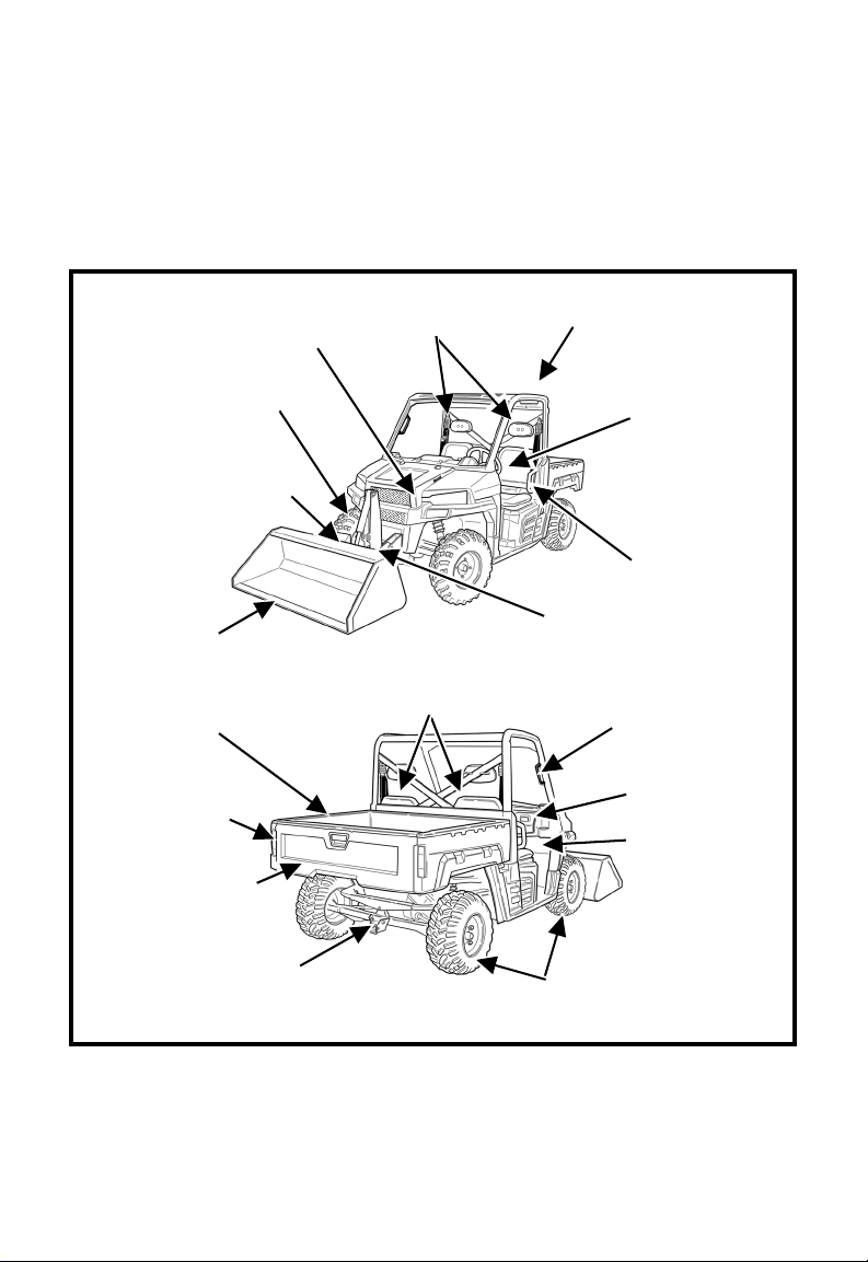
Learn about the Utility Vehicle from this Handbook, Owner’s Manual and safety
[1] OPS - Occupant Protective Structure, per ANSI / OPEI B71.9-2012.
LIFT
CYLINDER
BUCKET
ATTACHMENT
PRO-TACH and
ATTACHMENT ARM
NA5881A
[1] OPS STRUCTURE
RECEIVER
HITCH
TAILGATE
CARGO
BOX
OPERATOR & PASSENGER
SEATS WITH SEATBELTS
TILT
CYLINDER
NA5882A
TIRES
HIP
RESTRAINT (2)
HEADRESTS
OPERATOR’S
HANDBOOK
TAILLIGHTS /
BRAKE LIGHTS (2)
OWNER’S
MANUAL
STORAGE
COMPARTMENT
FRONT
LIGHTS
GRAB
HANDLE
labels (decals). See Owner’s Manual for full detailed illustrations. Replace
damaged or missing labels (decals) as shown in the Owner’s Manual. Ask the
dealer about equipment for each application. Refer to the Owner’s Manual and
dealer regarding attachments for Vehicle Load Capacity. For special jobs, ask
your dealer about necessary approved equipment; such as enclosures or special
lights. See your dealer for replacement manuals, safety labels and training
materials.
9925252 2
Page 3
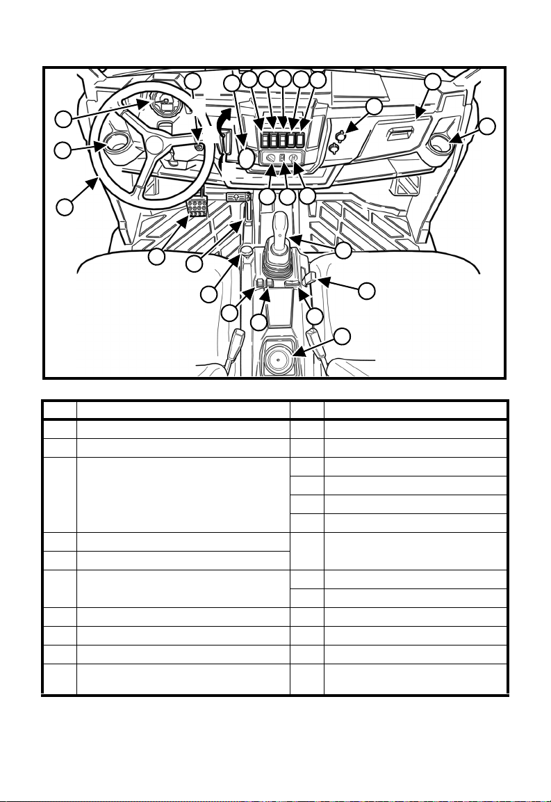
INSTRUMENT PANEL AND OPERATOR CONTROLS
NA5901B
C
B
1
11
11
10
2
3
4 5
6
7
8
9
11
12
13
14
15
16
17
18
19
20
21
22
23
A
D
REF. FUNCTION REF. FUNCTION
1. Instrument Panel (See Page 4) 11. Cup Holder (3)
2. Key Switch 12. Fan Speed Switch (Optional)
3. Gear Selector Lever
A. - Move up for Low Gear
B. - Move up for High Gear
C. - Neutral Position
D. - Move down for Park Position
4. Light Switch (OFF - Low - High) 17. Travel Control Pedal (Forward /
5. Drive Mode Switch
6. Cargo Box - With Power Lift Assist
Switch (Optional)
7. Optional Switch Locations 20. PTO Switch (Page 5)
8. Optional Switch Locations 21. Joystick Lock Switch (Page 5)
9. 12 Volt Accessory Outlet (2) 22. Lift Lock Switch (Page 5)
10. Storage Container (Owner’s Manual
TIP: Switch locations may vary from what is shown depending on options and
accessories installed on your vehicle.
See Owner’s Manual for more information.
and Tool Kit)
9925252 3
13. AC / Defrost Switch (Optional)
14. Temp Control Switch (Optional)
15. Steering Wheel
16. Brake Pedal
Reverse)
18. Joystick (See Page 5)
19. Engine Speed Control (Page 5)
23. Auxiliary Switch (Page 5)
Page 4
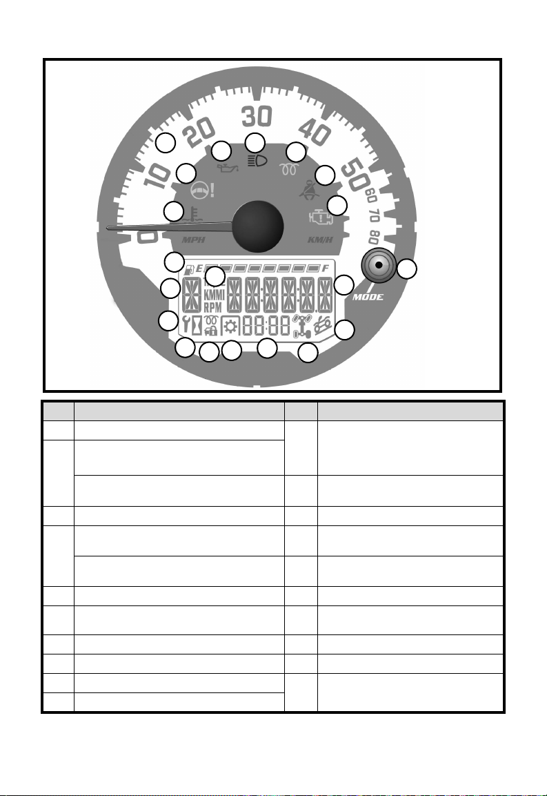
INSTRUMENT PANEL AND OPERATOR CONTROLS (CONT’D)
16
18
20
17
19
1
2
3
4
5
6
7
8
9
10
11
13
14
15
P-97832A
12
REF. FUNCTION REF. FUNCTION
1 Speedometer (KM/H or MPH) 11 Hourmeter, Trip Meter, Odometer,
2 Engine Coolant Temperature Indicator
(Red Light)
Hydraulic Fluid Temperature Indicator
(Red Light)
3 Not used for this model (Orange Light) 13 Drive Mode Indicator
4 Engine Oil Pressure Indicator (Red
Light)
Hydraulic Fluid Filter Plugged Indicator
(Red Light)
5 High Beam Indicator (Blue Light) 16 Not used for this model
6 Engine Pre-Heat Indicator (Orange
Light)
7 Fasten Seat Belt Indicator (Red Light) 18 Service Interval Symbol
8 Check Engine Light (Orange Light) 19 Gear Selector Indicator
9 Mode Button 20 Trip Meter (KM or Mi), RPM
10 Fuel Level Indicator
9925252 4
Tachometer, Battery Voltage,
Engine Coolant Temperature,
Service Interval, Check Engine
12 Not used for this model
14 Clock / PTO RPM
15 PTO Indicator
17 Hourmeter Symbol
Symbols
Page 5
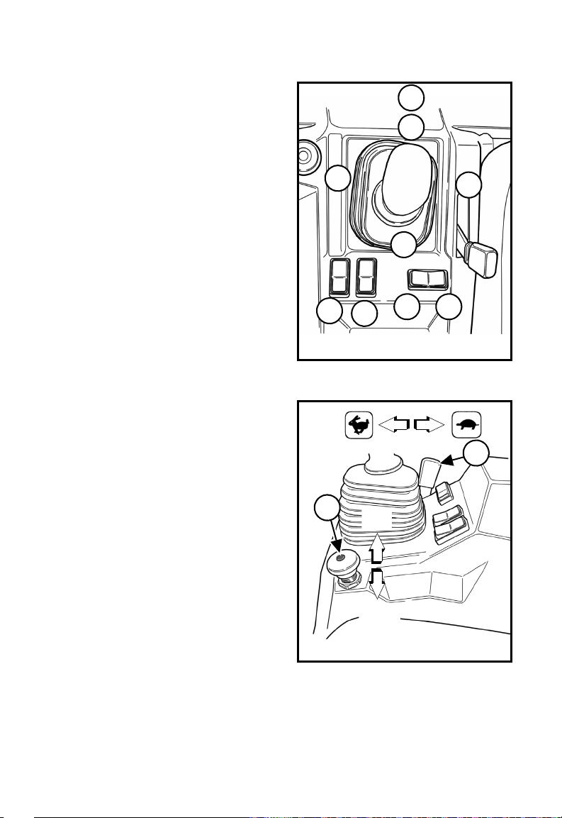
INSTRUMENT PANEL AND OPERATOR CONTROLS (CONT’D)
3
2
1
4
5
6
7
NA5909
8 9
NA5910
1
3
OFF
ON
Hydraulic Controls
1. Raise attachment arm.
2. Lower attachment arm.
3. Float position:
- Joystick pushed fully forward
(Item 3)
- Attachment will follow ground
as vehicle moves backward.
- Move joystick backward (Item 2)
to deactivate float.
4. Tilt attachment forward.
5. Tilt attachment backward.
6. Press switch for joystick lockout.
7. Press switch for tilt lockout.
8. Press and hold switch (Item 8) to
the left to activate the female
coupler.
9. Press and hold switch (Item 9) to
the right to activate the male
coupler.
PTO Controls
TIP: PTO switch must be in the
1. Press center button and lift PTO
2. Push PTO knob DOWN to
TIP: Do Not engage PTO system at
3. Increase the engine speed to the
OFF position to start engine.
knob UP to engage (ON).
disengage (OFF).
higher engine RPM with
attachment under load.
Always engage PTO system
at lower engine RPM and
attachment under NO load
condition.
desired RPM specified for your
attachment. See your attachment
Owner’s Manual for the correct
PTO RPM.
9925252 5
Page 6

DAILY INSPECTION
WARNING
Use the Occupant Protective Structure (OPS), which was designed for
the Utility Vehicle. Non-approved OPS structure modifications can cause
loss of operator protection and result in serious injury or death. Always
fasten seat belt when operating.
WARNING
Never use the machine in an atmosphere with explosive dust or gases or
where exhaust can contact flammable material. Explosion or fire can result.
AVOID INJURY OR DEATH
• Check seat belts and replace if damaged.
• Check OPS structure and fasteners.
• Check Safety Labels (Decals). Replace if damaged.
• Check frame fasteners - Inspect and insure tightness.
• Clean engine of flammable material.
• Clean pedals and operator’s area.
• Check engine oil level, fuel level, hydraulic fluid level, brake fluid level, engine
coolant level and engine air filter and pre-filter.
• Check tire condition and tire pressure. Check wheel fasteners for proper
torque.
• Check the travel control system, brake system, engine speed control system
and pedal travel.
• Check the front suspension, rear suspension and steering.
• Check the headlights, taillights, indicator lights and switches.
• Check PTO shaft splines, guards and shields. Replace if damaged or missing.
See Owner’s Manual for complete daily check list and maintenance procedures.
9925252 6
Page 7

STARTING AND DRIVING THE UTILITY VEHICLE
NA5178
NA5285
3
NEUTRAL
HIGH
LOW
PARK
See Owner’s Manual for more information.
WARNING
Hitting obstructions at high speeds
can cause serious injury or death.
Always fasten seat belt when
operating.
NA5287
AVOID INJURY OR DEATH
WARNING
Keep bystanders away from the
work area. DO NOT allow riders
in the cargo box.
NA5286
6
START
ON
OFF
2
1. Be sure load (if any) is secured.
2. Connect the seat belt. Adjust so
that the belt fits snug around the
lower part of your hips and over
the shoulder. Passenger must
also fasten seat belt.
3. Put the gear selector lever in the
PARK position.
4. Travel Control Pedal must be in
Neutral and PTO must be
disengaged (OFF).
5. Press and hold the brake pedal.
Tip: Engine will not start unless: Gear
selector is in Park or Neutral,
travel control pedal is in neutral
and PTO is OFF.
6. Turn the key to ON position and
wait for the glow plug light to turn
OFF, turn the key to START
position (for improved cold
weather starting, additional key
cycles maybe required). Release
key when the engine starts.
7. Allow engine to warm to
operating temperature.
8. Move the gear selector lever to
Low or High gear.
9. Release the brake pedal and
slowly press the travel control
pedal in the desired direction of
travel. (The further the pedal is
pressed, the faster the machine
will move.)
9925252 7
Page 8
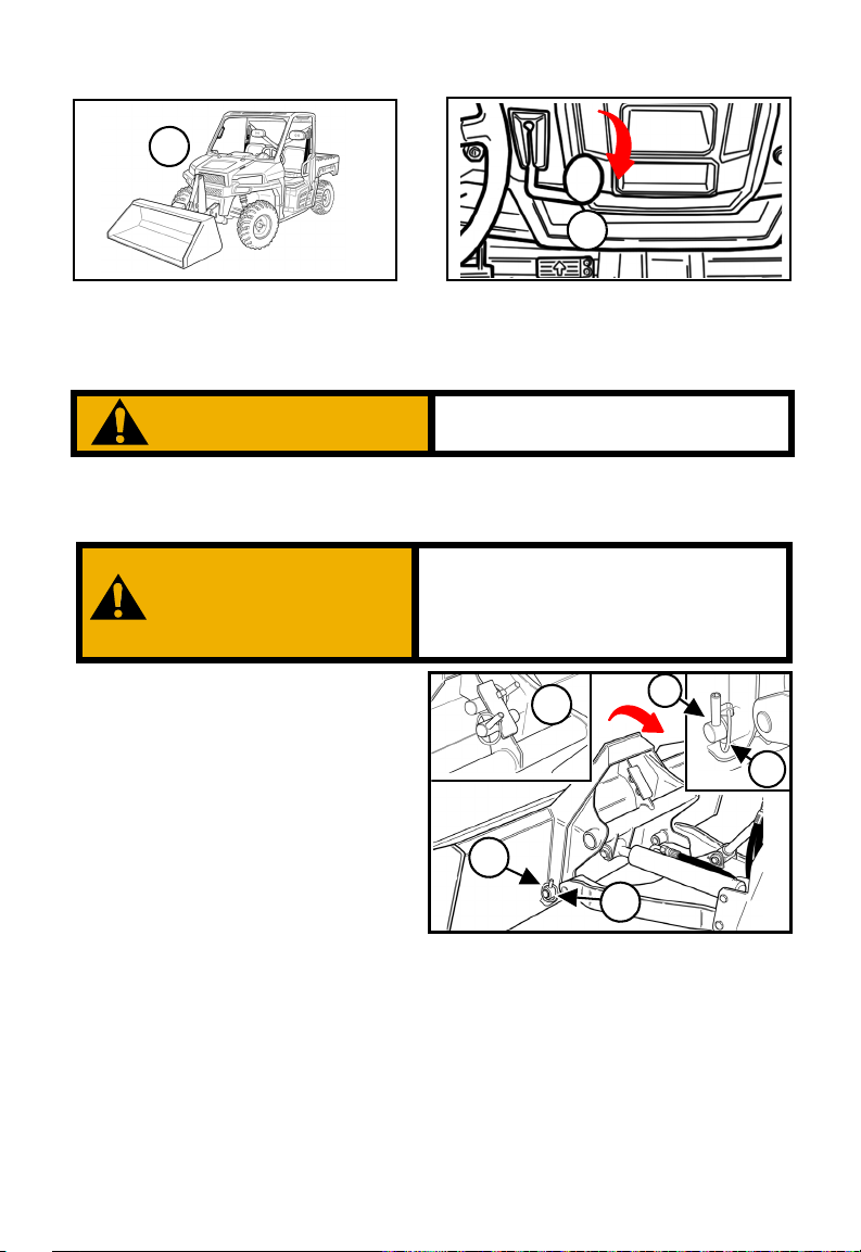
LEAVING THE VEHICLE
NA5901
2
1
NA5920
1. Lower the attachment arm and
put the attachment flat on the
ground.
2. Move the gear selector lever to
Park. Disengage the PTO
system (if equipped). Stop the
engine and remove the key.
WARNING
Always park vehicle on flat level
ground.
Attachment pins must be fully
installed and secured with the retainer
pins. Failure to fully install and secure
pins can allow the attachment to come
off and cause serious injury or death.
WARNING
1. Slowly drive forward until the
front edge of the attachment
interface is completely under
the top lip of the attachment.
2. Tilt the attachment interface
backward until the attachment
is slightly off the ground.
3. Move gear selector to PARK
and stop the engine.
4. Remove the two pins from the
storage location. Install the
pin (Item 1) and retainer pin
(Item 2), both sides, to secure
the attachment to the
attachment interface.
5. Keep pins in their storage
location (Item 3) when no
attachment is installed.
NA5915
3
2
1
1
2
PUTTING ON THE ATTACHMENT USING PRO-TACH
9925252 8
Page 9

AUXILIARY HYDRAULIC CONTROL
Auxiliary Operation:
Press switch (Item 1) to the left to
activate the female coupler. Press
switch (Item 1) to the right to
activate the male coupler.
Relieving Hydraulic Pressure:
With engine stopped (key switch
ON) and attachment flat on
ground, move auxiliary hydraulic
switch (Item 1) to the right and
left several times.
NA5909
1
Tip: The PTO has a rated speed of
2000 RPM.
1. Install the attachment on the
interface. See Page 8.
2. Connect the PTO driveline
(Item 1) to the utility vehicle
PTO shaft.
Tip: The PTO driveline must have a
means to retain it to the
attachment PTO shaft. Make
sure the driveline is of
adequate length and that the ujoints are in the correct phase.
NA5913
1
IMPORTANT
Do not exceed the rated attachment
PTO speed of 2000 RPM. Damage
to the attachment could occur from
over speeding. Disengage PTO for
road travel.
WARNING
AVOID INJURY OR DEATH
• Keep PTO shields and all guards
in place.
• Keep hands, legs, feet and
clothing away.
• Replace damaged or missing
shields and guards.
INSTALLING THE PTO DRIVELINE (If Equipped)
See Owner’s Manual for more information.
9925252 9
Page 10

WARNING
• Do Not exceed maximum Cargo Box Load.
• Do Not drive vehicle with Cargo Box raised.
• Make sure loads in Cargo Box are secured.
• Slow down when turning. Do Not make sharp turns.
NA5334
1
NA5333
RAISING AND LOWERING THE CARGO BOX
Cargo Box - With Lift Assist:
1. Ensure cargo is positioned
evenly and toward the front of
the cargo box.
2. Stand clear of the side of the
cargo box and pull up on the
cargo box release lever (Item 1).
3. Lift the front of the cargo box to
dump the cargo.
4. To lower cargo box, push down
on the front of the cargo box
until securely latched.
Cargo Box - With Power Lift
Assist Switch:
1. Press and hold the power lift
assist switch (Item 1) in the
raised position. Hold the switch
in the raised position until the
cargo box reaches the desired
height.
2. To lower cargo box, press and
hold the switch (Item 1) to the
lower position. Hold the switch
in the lower position until the
cargo box is fully lowered.
NA5926
NA5911
1
See Owner’s Manual for more information.
9925252 10
Page 11

DRIVING UP AND DOWN SLOPES
WARNING
NA5271
Going Down Slopes
NA5270
Going Up Slopes
With Loaded Attachment AND Cargo Box Empty
AVOID INJURY OR DEATH
• Keep heavy end of vehicle uphill.
• Go directly up or down a slope.
• Do not drive across slopes.
• Look in the direction of travel.
With Empty Attachment AND Cargo Box Loaded
NA5923
Going Down Slopes
NA5925
Going Up Slopes
When both are empty OR when both are loaded, the front and rear of the
vehicle are close to the same weight. You can either move forward OR
backward up and down slopes.
See Owner’s Manual for more information.
With Empty Attachment AND Cargo Box Empty
OR
With Loaded Attachment AND Cargo Box Loaded
9925252 11
Page 12

DRIVING UP AND DOWN SLOPES (CONT’D)
WARNING
• Do Not make sharp turns.
• Do Not exceed Vehicle Load
Capacity.
• Keep bystanders away.
• Do not leave vehicle with engine
running, attachment arm up or
gear selector not in PARK.
TIE DOWNS
TIE DOWNS
NA5246 NA5247
LOADING AND TRANSPORTING THE VEHICLE
When loading a vehicle with an attachment, drive forward onto transport vehicle.
Lower attachment to floor. Press the brake pedal and move the gear selector
lever to PARK. Stop the engine. Securely fasten vehicle to trailer or truck. Be sure
transport and towing vehicles are of adequate size and capacity.
See Owner’s Manual for more information.
9925252 12
Page 13

9925252 13
Page 14

AVOID INJURY OR DEATH
WARNING
• Stop and cool the engine before adding fuel. NO SMOKING!
• Do not service the machine or attachment with the PTO system engaged.
• Keep the engine area clean of flammable material and other debris.
• Do not wear loose clothing, long uncovered hair or jewelry near vehicle.
• Wear eye protection or other protective equipment as needed when servicing.
• Never use ether or starting fluid on diesel engine with glow plugs. Use only
starting aids as approved by the engine manufacturer.
• When connecting the booster battery for
negative cable
last to the engine, never at the battery. When removing the
jump start cables, always remove the negative cable (-) from engine first.
Never charge or
• Lead-acid batteries produce flammable and explosive gases. Keep arcs,
sparks, flames and lighted tobacco away from battery.
• Battery acid causes severe burns. In case of acid contact, wash immediately
with water for several minutes and get medical attention in case of eye
contact.
• Use a piece of cardboard to check for leaks. Leaking fluids under pressure
can enter the skin and cause serious injury. If fluid enters skin or eyes, get
immediate medical attention from a physician familiar with this injury.
This Handbook is available in an English edition or one of many other languages.
See your dealer for more information on translated versions.
Este Prontuario está disponible en su edición española o en cualquier otro
idioma. Póngase en contacto con su distribuidor para obtener más información
o para solicitar versiones traducidas.
Ce livret est disponible en anglais et dans de nombreuses autres langues.
Veuillez consulter votre concessionnaire pour plus d'informations sur les
versions traduites.
jump start a frozen battery.
jump start, always connect the
Printed in U.S.A.
© 2013 Polaris Sales Inc.
9925252 14
 Loading...