

Page 1
GENERAL INFORMATION
CHAPTER 1
GENERAL INFORMATION
VEHICLE IDENTIFICATION . . . . . . . . . . . . . . . . . . . . . . . . . . . . . . . . . . . . . . . . . . . . . 1.2
MODEL IDENTIFICATION . . . . . . . . . . . . . . . . . . . . . . . . . . . . . . . . . . . . . . . . . . . . . . . .1.2
ENGINE DESIGNATION NUMBER . . . . . . . . . . . . . . . . . . . . . . . . . . . . . . . . . . . . . . . . .1.2
VEHICLE IDENTIFICATION NUMBER (VIN). . . . . . . . . . . . . . . . . . . . . . . . . . . . . . . . . .1.2
VEHICLE AND ENGINE SERIAL NUMBER LOCATIONS. . . . . . . . . . . . . . . . . . . . . . . .1.2
SPECIFICATIONS. . . . . . . . . . . . . . . . . . . . . . . . . . . . . . . . . . . . . . . . . . . . . . . . . . . . . 1.3
MODEL:2006 HAWKEYE 2X4 . . . . . . . . . . . . . . . . . . . . . . . . . . . . . . . . . . . . . . . . . . . . .1.3
MODEL: 2006 HAWKEYE 4X4. . . . . . . . . . . . . . . . . . . . . . . . . . . . . . . . . . . . . . . . . . . . .1.3
MODEL:2006 HAWKEYE 2X4 . . . . . . . . . . . . . . . . . . . . . . . . . . . . . . . . . . . . . . . . . . . . .1.4
MODEL:2006 HAWKEYE 4X4 . . . . . . . . . . . . . . . . . . . . . . . . . . . . . . . . . . . . . . . . . . . . .1.5
GENERAL INFORMATION . . . . . . . . . . . . . . . . . . . . . . . . . . . . . . . . . . . . . . . . . . . . . . 1.6
PUBLICATION NUMBERS. . . . . . . . . . . . . . . . . . . . . . . . . . . . . . . . . . . . . . . . . . . . . . . .1.6
REPLACEMENT KEYS . . . . . . . . . . . . . . . . . . . . . . . . . . . . . . . . . . . . . . . . . . . . . . . . . .1.6
SPECIAL TOOLS . . . . . . . . . . . . . . . . . . . . . . . . . . . . . . . . . . . . . . . . . . . . . . . . . . . . . . .1.7
STANDARD TORQUE SPECIFICATIONS. . . . . . . . . . . . . . . . . . . . . . . . . . . . . . . . . . . .1.9
SAE TAP DRILL SIZES . . . . . . . . . . . . . . . . . . . . . . . . . . . . . . . . . . . . . . . . . . . . . . . . .1.10
METRIC TAP DRILL SIZES . . . . . . . . . . . . . . . . . . . . . . . . . . . . . . . . . . . . . . . . . . . . . .1.10
DECIMAL EQUIVALENTS . . . . . . . . . . . . . . . . . . . . . . . . . . . . . . . . . . . . . . . . . . . . . . .1.10
CONVERSION TABLE. . . . . . . . . . . . . . . . . . . . . . . . . . . . . . . . . . . . . . . . . . . . . . . . . .1.11
GLOSSARY OF TERMS. . . . . . . . . . . . . . . . . . . . . . . . . . . . . . . . . . . . . . . . . . . . . . . . .1.12
1
1.1
Page 2
GENERAL INFORMATION
VEHICLE IDENTIFICATION
Model Identification
The machine model number must be used with any correspondence regarding warranty or service.
Machine Model Number Identification
A 0 6 LB 2 7 A A
Year Designation
Basic Chassis
Designation
Engine Designation Number
ES30PFE ............................................................Single, Air Cooled, SOHC 4 Stroke, Electric Start
Vehicle Identification Number (VIN)
World
Mfg. ID
1 2 3 4 5 6 7 8 9 10 11 12 13 14 15 16 17
4 X A P B 2 0 A * 5 P 0 0 0 0 0 0
Vehicle Descriptor
}
}
}
}
Vehicle Identifier
}
Emissions &
Model Option
Engine Designation
}
Body Style
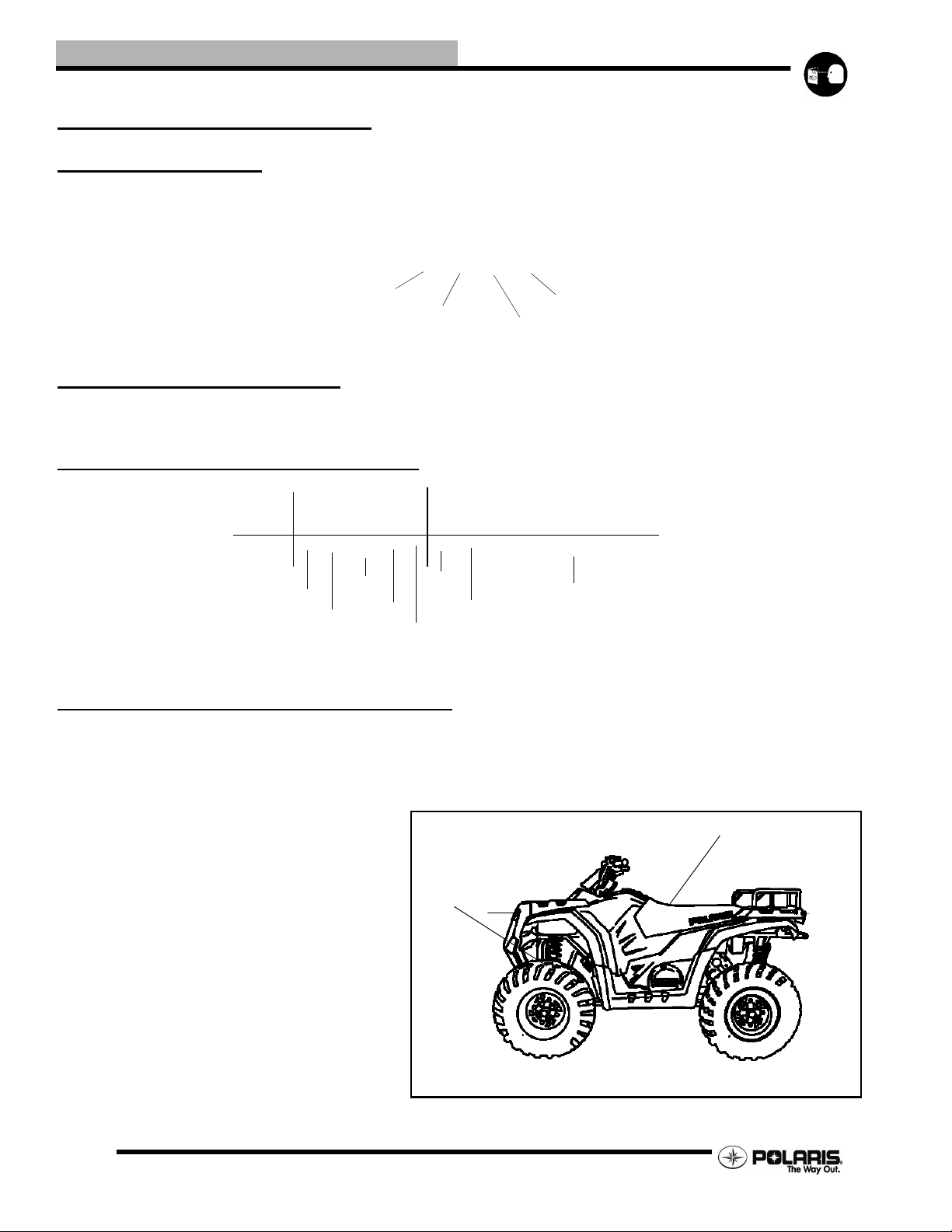
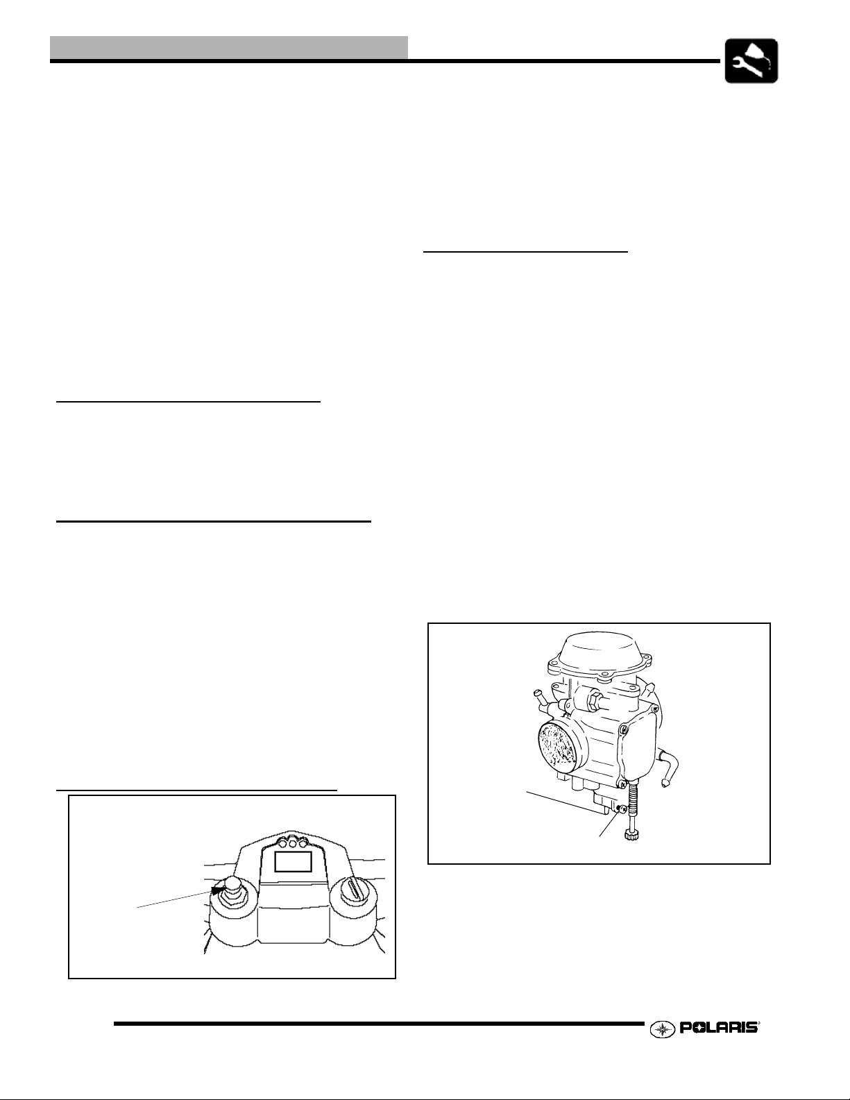
Vehicle and Engine Serial Number Locations
Whenever corresponding about an engine, be sure to refer to the engine model number and serial number. This information can be
found on the sticker applied to the recoil housing on the right side of engine.(A) An additional num ber is stamped on the center
top of crankcase beneath the cylinder coolant elbow.
The machine serial number (1- lower frame rail) and
engine number (2- right side engine) are important for
vehicle identification.
Engine
Powertrain
Emissions
Model
Year
Check Digit
1
Plant No
Individual Serial Number
* This could be either
a number or a letter
2
1.2
Page 3
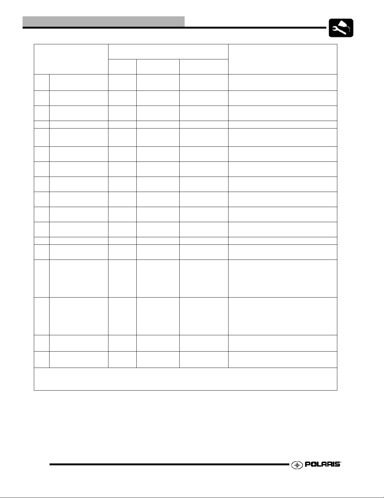
SPECIFICATIONS
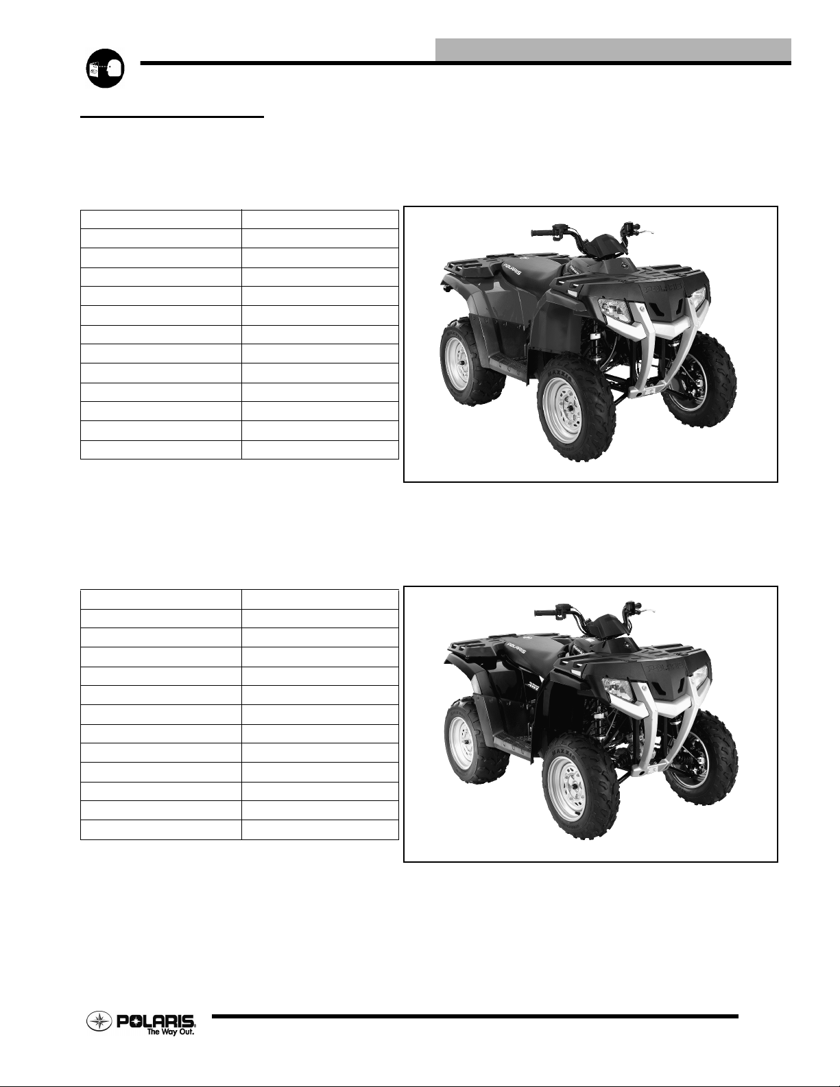
MODEL: 2006 HAWKEYE 2x4
MODEL NUMBER: . . . . . . . . .A06LB27AA
ENGINE MODEL: . . . . . . . . . .ES30PFE
Category Dimension
Length 74 in./188 cm
Width 42 in./107 cm
Height 45.5 in./116 cm
Wheel Base 46 in./117 cm
Ground Clearance 8 in./20.3 cm
Dry Weight 525 lbs./238 kg
Gross Vehicle Weight 930 lbs./422 kg
Front Rack Capacity 70 lbs./31.75 kg
Rear Rack Capacity 100 lbs./45 kg
Towing Capacity 750 lbs./340 kg
Hitch Tongue Weight 75 lbs./34 kg
Body Style Recreational/Utility
GENERAL INFORMATION
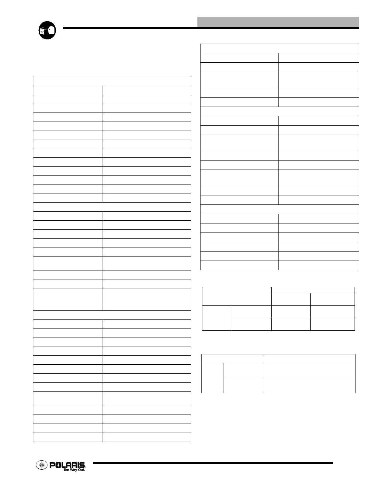
MODEL: . . . . . . . . . . . . 2006 HAWKEYE 4x4
MODEL NUMBER: . . . . . . . . .A06LD27AA
ENGINE MODEL: . . . . . . . . . .ES30PFE
Category Dimension
Length 74 in./188 cm
Width 42 in./107 cm
Height 45.5 in./116 cm
Wheel Base 46 in./117 cm
Ground Clearance 8 in./20.3 cm
Dry Weight 550 lbs./250 kg
Gross Vehicle Weight 930 lbs./422 kg
Front Rack Capacity 70 lbs./31.75 kg
Rear Rack Capacity 100 lbs./45 kg
Towing Capacity 750 lbs./340 kg
Hitch Tongue Weight 75 lbs./34 kg
Body Style Recreational/Utility
1.3
Page 4

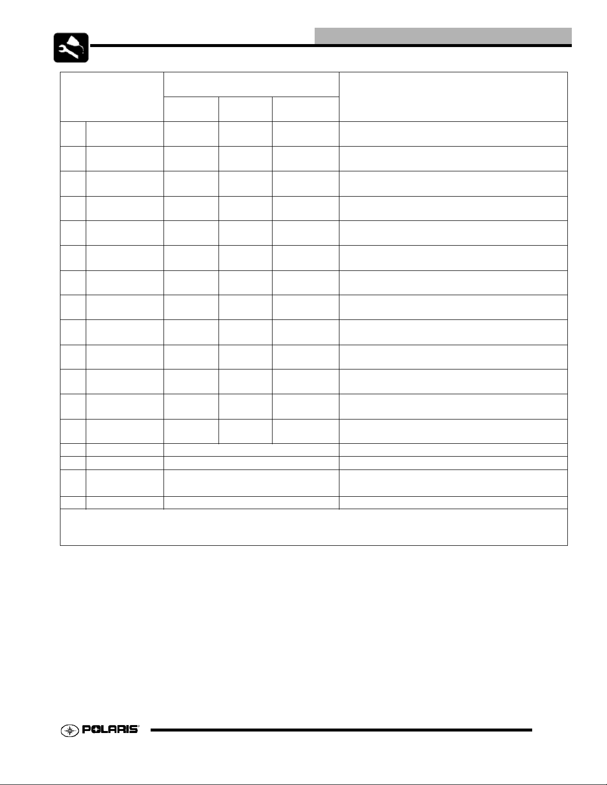
GENERAL INFORMATION
MODEL: 2006 HAWKEYE 2x4
MODEL NUMBER: A06LB27AA
ENGINE MODEL: ES30PFE
Engine
Platform Fuji 4 stroke, Single Cylinder
Engine Model Number ES300PFE010
Engine Displacement 299cc
Number of Cylinders 1
Bore & Stroke (mm) 78.5 x 68 mm
Compression Ratio 9.2:1 Full Stroke
Compression Pressure Compression Relase 60-90 psi
Engine Idle Speed
Cooling System/Capacity Air/Oil Cooled
Overheat Warning
Lubrication Wet Sump
Oil Requirements Polaris 0W-50 / 2 qts (1.9L)
Exhaust System Single Pipe - USFS Approved
Carburetion
Carburetor model Mikuni BST 34mm
Main Jet 147.5
Pilot Jet 42.5
Jet Needle 4HB42-5
Needle Jet 0-4m
Pilot/Air Screw 2.5 Turns Out (Initial setting)
Float Height 13mm from carburetor body
Fuel Delivery Fuel Pump
Fuel Capacity /
Requirement
Electrical
Alternator Output 250 watt / 18.6 Amp @ 6000
Voltage Regulator 3-phase
Lights : High Beam --
Low Beam 37.5 watts
Brake 12V / 26.9 watts
Tail 12V / 8.26 watts
Ignition System DC CDI
Ignition Timing BTDC 30+/-2deg. @ 5000 RPM
Spark plug / Gap NGK CR8E
Battery / Model / Amp Hr Conventional 14 Amp/hr
Circuit Breakers
Fusible Link / 15 amp Main / 15 Amp Accsy
Starting Electric / Recoil Back-up
Indicator Panel LCD / Indicator lights
1300 RPM
None
4.5 gal. (17 L)
87 Octane (minimum)
89 Oxygenated
.031 in. / .8 mm
Drivetrain
Transmission Type H-N-R
Transmission Capacity 15.2 oz. (450 ml)
Gear Ratio : Foward
Reverse
15.18:1
14.05:1
Clutch Type CVT w/EBS
Belt 3211108
Steering / Suspension
Front Suspension / Shock Mac Pherson Strut
Front Travel 7 in. / 17.8 cm
Rear Suspension
Style / Shock
Independent
Coil-over Adjustable
Rear Travel 8 in. / 20.3 cm
Ground Clearance 8 in. / 20.3 cm
Shock Preload Adjustment
Front / Rear
Front - Cam
Rear - Cam
Turning Radius 62.5 in. (159 cm) unloaded
Toe Out 0-1/16 in. (0-.159 mm)
Wheels / Brakes
Tire/Rim Size - Front 22 x 7-12
Tire/Rim Size - Rear 22 x 10-12
Air Press. F/R Tires 3-5 psi
Brake - Front Single Control Hydraulic Disc
Brake - Rear Single Control Hydraulic Disc
Brake Fluid Polaris DOT 3 or 4 Brake Fluid
JETTING CHART
Altitude
Meters
(Feet)
0-1800
(0-6000)
1800-3700
(6000-12000)
AMBIENT TEMPERATURE
Below 40o F
o
Below 5
C
152.5 147.5
147.5 142.5
Above +40
Above +5
o
F
o
C
CLUTCH CHART
Altitude Shift Weight
Meters
(Feet)
0-1800
(0-6000)
1800-3700
(6000 - 12000)
14 g (Yellow)
5412989
12 g (Red)
5412987
1.4
Page 5
GENERAL INFORMATION
MODEL: 2006 HAWKEYE 4x4
MODEL NUMBER: A06LD27AA
ENGINE MODEL: ES30PFE
Engine
Platform Fuji 4 stroke, Single Cylinder
Engine Model Number ES300PFE010
Engine Displacement 299cc
Number of Cylinders 1
Bore & Stroke (mm) 78.5 x 68 mm
Compression Ratio 9.2:1 Full Stroke
Compression Pressure Compression Relase 60-90 psi
Engine Idle Speed
Cooling System/Capacity Air/Oil Cooled
Overheat Warning
Lubrication Wet Sump
Oil Requirements Polaris 0W-50 / 2 qts (1.9L)
Exhaust System Single Pipe - USFS Approved
Carburetion
Carburetor model Mikuni BST 34mm
Main Jet 147.5
Pilot Jet 42.5
Jet Needle 4HB42-5
Needle Jet 0-4m
Pilot/Air Screw 2.5 Turns Out (Initial setting)
Float Height 13mm from carburetor body
Fuel Delivery Fuel Pump
Fuel Capacity /
Requirement
Electrical
Alternator Output 250 watt / 18.6 Amp @ 6000
Voltage Regulator 3-phase
Lights : High Beam --
Low Beam 37.5 watts
Brake 12V / 26.9 watts
Tail 12V / 8.26 watts
Ignition System DC CDI
Ignition Timing BTDC 30+/-2deg. @ 5000 RPM
Spark plug / Gap NGK CR8E
Battery / Model / Amp Hr Conventional 14 Amp/hr
Circuit Breakers
Fusible Link / 15 amp Main / 15 Amp Accsy
Starting Electric / Recoil Back-up
Indicator Panel LCD / Indicator lights
1300 RPM
None
4.5 gal. (17 L)
87 Octane (minimum)
89 Oxygenated
.031 in. / .8 mm
Drivetrain
Transmission Type H-N-R
Transmission Capacity 15.2 oz. (450 ml)
Gear Ratio : Front Output
Rear Output
Fwd 5.17:1 / Rev 4.79:1
Fwd 15.18:1 / Rev 14.05:1
Clutch Type CVT w/EBS
Belt 3211108
Steering / Suspension
Front Suspension / Shock Mac Pherson Strut
Front Travel 7 in. / 17.8 cm
Rear Suspension
Style / Shock
Independent
Coil-over Adjustable
Rear Travel 8 in. / 20.3 cm
Ground Clearance 8 in. / 20.3 cm
Shock Preload Adjustment
Front / Rear
Front - Cam
Rear - Cam
Turning Radius 62.5 in. (159 cm) unloaded
Toe Out 0-1/16 in. (0-.159 mm)
Wheels / Brakes
Tire/Rim Size - Front 22 x 7-12
Tire/Rim Size - Rear 22 x 10-12
Air Press. F/R Tires 3-5 psi
Brake - Front Single Control Hydraulic Disc
Brake - Rear Single Control Hydraulic Disc
Brake Fluid Polaris DOT 3 or 4 Brake Fluid
JETTING CHART
Altitude
Meters
(Feet)
0-1800
(0-6000)
1800-3700
(6000-12000)
AMBIENT TEMPERATURE
Below 40o F
o
Below 5
C
152.5 147.5
147.5 142.5
Above +40
Above +5
o
F
o
C
CLUTCH CHART
Altitude Shift Weight
Meters
(Feet)
0-1800
(0-6000)
1800-3700
(6000 - 12000)
14 g (Yellow)
5412989
12 g (Red)
5412987
1.5
Page 6

GENERAL INFORMATION
GENERAL INFORMATION
PUBLICATION NUMBERS
Year Model Model No. Owner’s Manual PNParts Manual
PN
2006 Hawkeye 2x4 A06LB27AA 9920202 9920207 9920208
2006 Hawkeye 4x4 A06LD27AB,AC 9920202 9920207 9920208
NOTE: When ordering service parts be sure to use the correct parts manual.
NOTE: Some manuals can be found at the Polaris website: www.polarisindustries.com or purchased from
www.purepolaris.com.
Parts Micro
Fiche PN
REPLACEMENT KEYS
Replacement keys can be made from the original key. To identify which series the key is, take the first two digits on the original key
and refer to the chart to the right for the proper part number. Should both keys become lost, replacement of the ignition switch
assembly is necessary.
Series # Part Number
20 4010278
21 4010278
22 4010321
23 4010321
27 4010321
28 4010321
31 4110141
32 4110148
67 4010278
68 4010278
1.6
Page 7
GENERAL INFORMATION
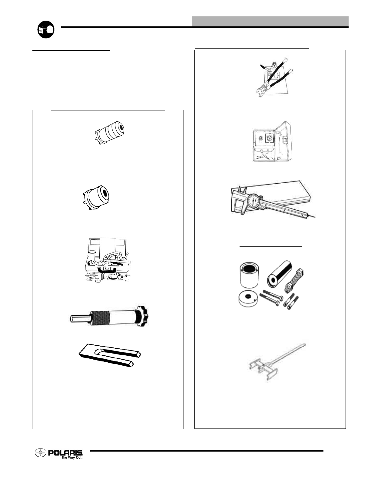
SPECIAL TOOLS
Special Tools may be required while servicing your machine.
Some of the tools listed are mandatory and other tools may be
substituted with a similar tool, if available. Polaris
recommends the use of Polaris special tools when servicing
any Polaris product.
Standard Tools and Engine Tools
2871293 - B - Crankshaft
Slotted Nut Socket
PA - 47344 - Balance Shaft
Slotted Nut Socket
Standard Tools and Engine Tools
2870569 - Crankshaft True Kit
PV - 35667 - A - Cylinder Leakdown Tester
PU - 45432 - Caliper or A Basic Caliper
2870975 - Mity Vac
TM
2870773 - C - Clip Install Tool
2870390 - Piston Support Block
PA-47478 - Drive Clutch Holder
Suspension Tools
2870871 - ATV Ball Joint Tool Kit
2870623 - Shock Spring Compressor
1.7
Page 8
GENERAL INFORMATION
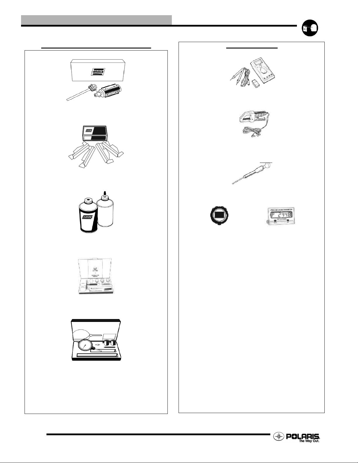
Standard Tools and Engine Tools
2870303- Hone Kit
2870305 - Stone Replacement Kit
Electrical Tools
PV -43568 - FlukeTM 77 Multimeter
PV-39617 - Current Clamp
2870836 - Battery Hydrometer
2870588 - Hone Oil (12 OZ.)
2200634 - Valve Seat Reconditioning Kit
2870459 - Dial Indicator
8712500 - PV-39951-A
Tachometer Tachometer
1.8
Page 9
GENERAL INFORMATION
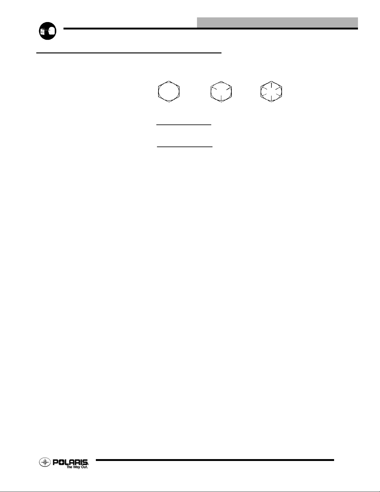
STANDARD TORQUE SPECIFICATIONS
The following torque specifications are to be used as a general guideline. FOR SPECIFIC TORQUE VALUES OF FASTENERS Refer to
exploded views in the appropriate section. There are exceptions in the steering, suspension, and engine sections.
Bolt Size Threads/In Grade 2 Grade 5 Grade 8
Torque in. lbs. (Nm)
#10 - 24 . . . . . . . . . . . . . . . . . 27 (3.1) . . . . . . . . . 43 (5.0) . . . . . . . . .60 (6.9)
#10 - 32 . . . . . . . . . . . . . . . . . 31 (3.6) . . . . . . . . . 49 (5.6) . . . . . . . . .68 (7.8)
Torque ft. lbs. (Nm)*
1/4 - 20 . . . . . . . . . . . . . . . . . 5 (7). . . . . . . . . . . . 8 (11). . . . . . . . . . .12 (16)
1/4 - 28 . . . . . . . . . . . . . . . . . 6 (8). . . . . . . . . . . . 10 (14) . . . . . . . . .14 (19)
5/16 - 18 . . . . . . . . . . . . . . . . . 11(15) . . . . . . . . . . 17 (23) . . . . . . . . .25 (35)
5/16 - 24 . . . . . . . . . . . . . . . . . 12(16) . . . . . . . . . . 19 (26) . . . . . . . . .29 (40)
3/8 - 16 . . . . . . . . . . . . . . . . . 20(27) . . . . . . . . . . 30 (40) . . . . . . . . .45 (62)
3/8 - 24 . . . . . . . . . . . . . . . . . 23(32) . . . . . . . . . . 35 (48) . . . . . . . . .50 (69)
7/16 - 14 . . . . . . . . . . . . . . . . . 30(40) . . . . . . . . . . 50 (69) . . . . . . . . .70 (97)
7/16 - 20 . . . . . . . . . . . . . . . . . 35(48) . . . . . . . . . . 55 (76) . . . . . . . . .80 (110)
1/2 - 13 . . . . . . . . . . . . . . . . . 50(69) . . . . . . . . . . 75 (104) . . . . . . . .110 (152)
1/2 - 20 . . . . . . . . . . . . . . . . . 55(76) . . . . . . . . . . 90 (124) . . . . . . . .120 (166)
Metric / Torque
6 x 1.0. . . . . . . . . . . 72-78 In.lbs.. . . . . . . . .8 x 1.25 14-18 ft.lbs. . . .10 x 1.25 26-30 ft.lbs.
1.9
Page 10
GENERAL INFORMATION
SAE TAP DRILL SIZES
Thread Size/ Drill Size Thread Size / Drill Size
#0-80 3/64 1/2-13 27/64
#1-64 53 1/2-20 29/64
#1-72 53 9/16-12 31/64
#2-56 51 9/16-18 33/64
#2-64 50 5/8-11 17/32
#3-48 5/64 5/8-18 37/64
#3-56 45 3/4-10 21/32
#4-40 43 3/4-16 11/16
#4-48 42 7/8-9 49/64
#5-40 38 7/8-14 13/16
#5-44 37 1-8 7/8
#6-32 36 1-12 59/64
#6-40 33 1 1/8-7 63/64
#8-32 29 1 1/8-12 1 3/64
#8-36 29 1 1/4-7 1 7/64
#10-24 24 1 1/4-12 1 11/64
#10-32 21 1 1/2-6 1 11/32
#12-24 17 1 1/2-12 1 27/64
#12-28 4.6mm 1 3/4-5 1 9/16
1/4-20 7 1 3/4-12 1 43/64
1/4-28 3 2-4 1/2 1 25/32
5/16-18 F 2-12 1 59/64
5/16-24 I 2 1/4-4 1/2 2 1/32
3/8-16 O 2 1/2-4 2 1/4
3/8-24 Q 2 3/4-4 2 1/2
7/16-14 U 3-4 2 3/4
7/16-20 25/64
METRIC TAP DRILL SIZES
Tap Size Drill Size Decimal
Equivalent
3x.50 #39 0.0995 3/32
3x.60 3/32 0.0937 3/32
4x.70 #30 0.1285 1/8
4x.75 1/8 0.125 1/8
5x.80 #19 0.166 11/64
5x.90 #20 0.161 5/32
6x1.00 #9 0.196 13/64
7x1.00 16/64 0.234 15/64
8x1.00 J 0.277 9/32
8x1.25 17/64 0.265 17/64
9x1.00 5/16 0.3125 5/16
9x1.25 5/16 0.3125 5/16
10x1.25 11/32 0.3437 11/32
10x1.50 R 0.339 11/32
11x1.50 3/8 0.375 3/8
12x1.50 13/32 0.406 13/32
12x1.75 13/32 0.406 13/32
Nearest
Fraction
DECIMAL EQUIVALENTS
1/64 . . . . . . . . . .. . . . . . . .0156
1/32. . . . . . .. . . . . . . .0312 . . .1 mm= .0394"
3/64 . . . . . . . . . .. . . . . . . .0469
1/16. . . . . . .. . . . . . . .0625
5/64 . . . . . . . . . .. . . . . . . .0781 . . .2 mm = .0787"
3/32. . . . . . .. . . . . . . .0938
7/64 . . . . . . . . . .. . . . . . . .1094 . . .3 mm =.1181"
1/8. . . . . . . . .1250
9/64 . . . . . . . . . .. . . . . . . .1406
5/32. . . . . . .. . . . . . . .1563 . . .4 mm = .1575"
11/64 . . . . . . . . . .. . . . . . . .1719
3/16. . . . . . .. . . . . . . .1875 . . .5mm= .1969"
13/64 . . . . . . . . . .. . . . . . . .2031
7/32. . . . . . .. . . . . . . .2188
15/64 . . . . . . . . . .. . . . . . . .2344 . . .6 mm = .2362"
1/4. . . . . . . . .25
17/64 . . . . . . . . . .. . . . . . . .2656 . . .7 mm = .2756"
9/32. . . . . . .. . . . . . . .2813
19/64 . . . . . . . . . .. . . . . . . .2969
5/16. . . . . . .. . . . . . . .3125 . . .8mm= .3150"
21/64 . . . . . . . . . .. . . . . . . .3281
11/32. . . . . .. . . . . . . .3438 . . .9 mm = .3543"
23/64 . . . . . . . . . .. . . . . . . .3594
3/8. . . . . . . . .375
25/64 . . . . . . . . . .. . . . . . . .3906 . . .10 mm = .3937"
13/32. . . . . .. . . . . . . .4063
27/64 . . . . . . . . . .. . . . . . . .4219 . . .11 mm =.4331"
7/16. . . . . . .. . . . . . . .4375
29/64 . . . . . . . . . .. . . . . . . .4531
15/32. . . . . .. . . . . . . .4688 . . .12 mm = .4724"
31/64 . . . . . . . . . .. . . . . . . .4844
1/2. . . . . . . . .5 . . . . . . . . . . . .13mm = .5118"
33/64 . . . . . . . . . .. . . . . . . .5156
17/32. . . . . .. . . . . . . .5313
35/64 . . . . . . . . . .. . . . . . . .5469 . . .14 mm = .5512"
9/16. . . . . . .. . . . . . . .5625
37/64 . . . . . . . . . .. . . . . . . .5781 . . .15 mm = .5906"
19/32. . . . . .. . . . . . . .5938
39/64 . . . . . . . . . .. . . . . . . .6094
5/8. . . . . . . . .625 . . . . . . . . . .16mm=. 6299"
41/64 . . . . . . . . . .. . . . . . . .6406
21/32. . . . . .. . . . . . . .6563 . . .17 mm =.6693"
43/64 . . . . . . . . . .. . . . . . . .6719
11/16. . . . . .. . . . . . . .6875
45/64 . . . . . . . . . .. . . . . . . .7031 . . .18 mm = .7087"
23/32. . . . . .. . . . . . . .7188
47/64 . . . . . . . . . .. . . . . . . .7344 . . .19 mm = .7480"
3/4. . . . . . . . .75
49/64 . . . . . . . . . .. . . . . . . .7656
25/32. . . . . .. . . . . . . .7813 . . .20 mm = .7874"
51/64 . . . . . . . . . .. . . . . . . .7969
13/16. . . . . .. . . . . . . .8125 . . .21 mm =.8268"
53/64 . . . . . . . . . .
27/32
55/64 . . . . . . . . . .. . . . . . . .8594 . . .22 mm = .8661"
7/8. . . . . . . . .875
57/64 . . . . . . . . . .. . . . . . . .8906 . . .23 mm = .9055"
29/32. . . . . .. . . . . . . .9063
59/64 . . . . . . . . . .. . . . . . . .9219
15/16. . . . . .. . . . . . . .9375 . . .24 mm = .9449"
61/64 . . . . . . . . . .. . . . . . . .9531
31/32. . . . . .. . . . . . . .9688 . . .25 mm = .9843"
63/64 . . . . . . . . . .. . . . . . . .9844
1 . . . . . . . . . 1.0
. . . . . . . .8281
. . . . . . . .8438
. . . . . .
1.10
Page 11
GENERAL INFORMATION
CONVERSION TABLE
Unit of Measure Multiplied by Converts to
ft. lbs. x 12 = in. lbs.
in. lbs. x .0833 = ft. lbs.
ft. lbs. x 1.356 = Nm
in. lbs. x .0115 = kg-m
Nm x .7376 = ft. lbs.
kg-m x 7.233 = ft. lbs.
kg-m x 86.796 = in. lbs.
kg-m x 10 = Nm
in. x 25.4 =mm
mm x .03937 = in.
in. x 2.54 = cm
mile (mi.) x 1.6 = km
km x .6214 = mile (mi.)
Ounces (oz.) x 28.3 5 = Grams (g)
Fluid Ounces (fl. oz.) x 29.57 = Cubic Centimeters (cc)
Cubic Centimeters (cc) x .03381 = Fluid Ounces (fl. oz.)
Grams (g) x 0.035 = Ounc es (oz.)
lb. x .454 = kg
kg x 2.2046 = lb.
Cubic inches (cu. in) x 16.387 = Cubic centimeters (cc)
Cubic centimeters (cc) x 0.061 = Cubic inches (cu. in)
Imperial pints (Imp pt.) x 0.568 = Liters (l)
Liters (l) x 1.76 = Imperial pints (Imp pt.)
Imperial quarts (Imp qt.) x 1.137 = Liters (l)
Liters (l) x 0.88 = Imperial quarts (Imp qt.)
Imperial quarts (Imp qt.) x 1.201 = US quarts (US qt.)
US quarts (US qt.) x 0.833 = Imperial quarts (Imp qt.)
US quarts (US qt.) x 0.946 = Liters (l)
Liters (l) x 1.057 = US quarts (US qt.)
US gallons (US gal) x 3.785 =Liters (l)
Liters (l) x 0.264 = US gallons (US gal)
Pounds - force per square inch (psi) x 6.895 = Kilopascals (kPa)
Kilopascals (kPa) x 0.145 = Pounds - force per square inch (psi)
Kilopascals (kPa) x 0.01 = Kilograms - force per square cm
Kilograms - force per square cm x 98.1 = Kilopascals (kPa)
π(3.14)xR
2
x H (height) = Cylinder Volume
°C to °F: 9 (°C + 40) ÷ 5 - 40 = °F
°F to °C: 5 (°F + 40)
÷ 9 - 40 = °C
1.11
Page 12

GENERAL INFORMATION
GLOSSARY OF TERMS
ABDC: After bottom dead center.
ACV: Alternating current voltage.
Alternator: Electrical generator producing voltage alternating current.
ATDC: After top dead center.
BBDC: Before bottom dead center.
BDC: Bottom dead center.
BTDC: Before top dead center.
CC: Cubic centimeters.
Center Distance: Distance between center of crankshaft and center of driven clutch shaft.
Chain Pitch: Distance between chain link pins (No. 35 = 3/8" or 1 cm). Polaris measures chain length in number of pitches.
CI: Cubic inches.
Clutch Buttons: Plastic bushings which aid rotation of the movable sheave in the drive and driven clutch .
Clutch Offset: Drive and driven clutches are offset so that drive belt will stay nearly straight as it moves along the clutch face.
Clutch Weights: Three levers in the drive clutch which relative to their weight, profile and engine RPM cause the drive clutch to close and
grip the drive belt.
Crankshaft Run-Out: Run-out or "bend" of crankshaft measured with a dial indicator while crankshaft is supported between centers on V
blocks or resting in crankcase. Measure at various points especially at PTO.
CVT: Centrifugal Variable Transmission (Drive Clutch System)
DCV: Direct current voltage.
Dial Bore Gauge: A cylinder measuring instrument which uses a dial indicator. Good for showing taper and out-of-round in the cylinder
bore.
Electrical Open: Open circuit. An electrical circuit which isn't complete.
Electrical Short: Short circuit. An electrical circuit which is completed before the current reaches the intended load. (i.e. a bare wire
touching the chassis).
End Seals: Rubber seals at each end of the crankshaft.
Engagement RPM: Engine RPM at which the drive clutch engages to make contact with the drive belt .
ft.: Foot/feet.
Foot Pound: Ft. lb. A force of one pound at the end of a lever one foot in length, applied in a rotational direction.
g: Gram. Unit of weight in the metric system.
gal.: Gallon.
ID: Inside diameter.
in.: Inch/inches.
Inch Pound: In. lb. 12 in. lbs. = 1 ft. lb.
2
: Kilograms per square centimeter.
kg/cm
kg-m: Kilogram meters.
Kilogram/meter: A force of one kilogram at the end of a lever one meter in length, applied in a rotational direction.
l or ltr: Liter.
2
: Pounds per square inch.
lbs/in
Left or Right Side: Always referred to based on normal operating position of the driver.
m: Meter/meters.
Mag: Magneto.
Magnetic Induction: As a conductor (coil) is moved through a magnetic field, a voltage will be generated in the windings. Mechanical
energy is converted to electrical energy in the stator.
mi.: Mile/miles.
mm: Millimeter. Unit of length in the metric system. 1 mm = approximately .040".
Nm: Newton meters.
OD: Outside diameter.
Ohm: The unit of electrical resistance opposing current flow.
oz.: Ounce/ounces.
Piston Clearance: Total distance between piston and cylinder wall.
psi.: Pounds per square inch.
PTO: Power take off.
qt.: Quart/quarts.
Regulator: Voltage regulator. Regulates battery charging system output at approx. 14.5 DCV as engine RPM increases.
Reservoir Tank: The fill tank in the liquid cooling system.
Resistance: In the mechanical sense, friction or load. In the electrical sense, ohms, resulting in energy conversion to heat.
RPM: Revolutions per minute.
Seized Piston: Galling of the sides of a piston. Usually there is a transfer of aluminum from the piston onto the cylinder wall.
Possible causes: 1) improper lubrication; 2) excessive temperatures; 3) insufficient piston clearance; 4) stuck piston rings.
Stator Plate: The plate mounted under the flywheel supporting the battery charging coils.
TDC: Top dead center. Piston's most outward travel from crankshaft.
Volt: The unit of measure for electrical pressure of electromotive force. Measured by a voltmeter in parallel with the circuit.
Watt: Unit of electrical power. Watts = amperes x volts.
WOT: Wide open throttle.
1.12
Page 13
CHAPTER 2
MAINTENANCE
MAINTENANCE
MAINTENANCE. . . . . . . . . . . . . . . . . . . . . . . . . . . . . . . . . . . . . . . . . . . . . . . . . . . . . . . 2.2
PERIODIC MAINTENANCE CHART . . . . . . . . . . . . . . . . . . . . . . . . . . . . . . . . . . . . . . . .2.2
MAINTENANCE CHART KEY . . . . . . . . . . . . . . . . . . . . . . . . . . . . . . . . . . . . . . . . . . . . .2.2
MAINTENANCE AND LUBRICATION . . . . . . . . . . . . . . . . . . . . . . . . . . . . . . . . . . . . . . .2.3
LUBRICANTS / FLUIDS . . . . . . . . . . . . . . . . . . . . . . . . . . . . . . . . . . . . . . . . . . . . . . . . 2.6
POLARIS LUBES/FLUIDS . . . . . . . . . . . . . . . . . . . . . . . . . . . . . . . . . . . . . . . . . . . . . . . .2.6
POLARIS LUBRICANTS,MAINTENANCE AND SERVICE PRODUCTS. . . . . . . . . . . . . 2.7
POLARIS LUBRICANT SYMBOL IDENTIFICATION. . . . . . . . . . . . . . . . . . . . . . . . . . . .2.8
VEHICLE INSPECTION / MAINTENANCE . . . . . . . . . . . . . . . . . . . . . . . . . . . . . . . . . . 2.8
PRE-RIDE / DAILY INSPECTION . . . . . . . . . . . . . . . . . . . . . . . . . . . . . . . . . . . . . . . . . .2.8
HAWKEYE HANDLEBAR COMPONENT LOCATIONS. . . . . . . . . . . . . . . . . . . . . . . . . .2.9
MAINTENANCE QUICK REFERENCE . . . . . . . . . . . . . . . . . . . . . . . . . . . . . . . . . . . . . .2.9
TRANSMISSION LUBRICATION. . . . . . . . . . . . . . . . . . . . . . . . . . . . . . . . . . . . . . . . . .2.11
FRONT GEARCASE LUBRICATION (4X4 ONLY). . . . . . . . . . . . . . . . . . . . . . . . . . . . .2.11
LUBRICATION / GREASE POINTS . . . . . . . . . . . . . . . . . . . . . . . . . . . . . . . . . . . . . . . .2.12
THROTTLE OPERATION - ALL MODELS. . . . . . . . . . . . . . . . . . . . . . . . . . . . . . . . . . .2.12
CHOKE (ENRICHER) ADJUSTMENT . . . . . . . . . . . . . . . . . . . . . . . . . . . . . . . . . . . . . .2.12
CARBURETOR DRAINING . . . . . . . . . . . . . . . . . . . . . . . . . . . . . . . . . . . . . . . . . . . . . .2.12
PILOT SCREW. . . . . . . . . . . . . . . . . . . . . . . . . . . . . . . . . . . . . . . . . . . . . . . . . . . . . . . .2.13
PILOT SCREW ADJUSTMENT . . . . . . . . . . . . . . . . . . . . . . . . . . . . . . . . . . . . . . . . . . .2.13
ELECTRONIC THROTTLE CONTROL (ETC SWITCH)/THROTTLE CABLE ADJUSTMENT2.14
FUEL SYSTEM. . . . . . . . . . . . . . . . . . . . . . . . . . . . . . . . . . . . . . . . . . . . . . . . . . . . . . . .2.14
FUEL LINES . . . . . . . . . . . . . . . . . . . . . . . . . . . . . . . . . . . . . . . . . . . . . . . . . . . . . . . . . .2.14
VENT LINES. . . . . . . . . . . . . . . . . . . . . . . . . . . . . . . . . . . . . . . . . . . . . . . . . . . . . . . . . .2.14
FUEL FILTER. . . . . . . . . . . . . . . . . . . . . . . . . . . . . . . . . . . . . . . . . . . . . . . . . . . . . . . . .2.14
COMPRESSION TEST. . . . . . . . . . . . . . . . . . . . . . . . . . . . . . . . . . . . . . . . . . . . . . . . . .2.15
ENGINE MOUNTS . . . . . . . . . . . . . . . . . . . . . . . . . . . . . . . . . . . . . . . . . . . . . . . . . . . . .2.15
ENGINE FASTENER TORQUE . . . . . . . . . . . . . . . . . . . . . . . . . . . . . . . . . . . . . . . . . . .2.15
BATTERY MAINTENANCE . . . . . . . . . . . . . . . . . . . . . . . . . . . . . . . . . . . . . . . . . . . . . .2.15
SPARK PLUG. . . . . . . . . . . . . . . . . . . . . . . . . . . . . . . . . . . . . . . . . . . . . . . . . . . . . . . . .2.16
IGNITION TIMING . . . . . . . . . . . . . . . . . . . . . . . . . . . . . . . . . . . . . . . . . . . . . . . . . . . . .2.17
MAIN AIR FILTER CLEANING. . . . . . . . . . . . . . . . . . . . . . . . . . . . . . . . . . . . . . . . . . . .2.17
AIR FILTER/PRE-FILTER SERVICE . . . . . . . . . . . . . . . . . . . . . . . . . . . . . . . . . . . . . . .2.17
AIR BOX SEDIMENT TUBE. . . . . . . . . . . . . . . . . . . . . . . . . . . . . . . . . . . . . . . . . . . . . .2.18
CVT DRAIN PLUG & DRYING. . . . . . . . . . . . . . . . . . . . . . . . . . . . . . . . . . . . . . . . . . . .2.18
ENGINE OIL LEVEL. . . . . . . . . . . . . . . . . . . . . . . . . . . . . . . . . . . . . . . . . . . . . . . . . . . .2.18
OIL AND FILTER CHANGE . . . . . . . . . . . . . . . . . . . . . . . . . . . . . . . . . . . . . . . . . . . . . .2.19
VALVE CLEARANCE ADJUSTMENT . . . . . . . . . . . . . . . . . . . . . . . . . . . . . . . . . . . . . .2.20
STEERING . . . . . . . . . . . . . . . . . . . . . . . . . . . . . . . . . . . . . . . . . . . . . . . . . . . . . . . . . . .2.20
TIE ROD END/STEERING INSPECTION . . . . . . . . . . . . . . . . . . . . . . . . . . . . . . . . . . .2.21
CAMBER AND CASTER . . . . . . . . . . . . . . . . . . . . . . . . . . . . . . . . . . . . . . . . . . . . . . . .2.21
TOE ALIGNMENT. . . . . . . . . . . . . . . . . . . . . . . . . . . . . . . . . . . . . . . . . . . . . . . . . . . . . .2.21
TOE ALIGNMENT ADJUSTMENT. . . . . . . . . . . . . . . . . . . . . . . . . . . . . . . . . . . . . . . . .2.22
EXHAUST CLEANING . . . . . . . . . . . . . . . . . . . . . . . . . . . . . . . . . . . . . . . . . . . . . . . . . .2.22
BRAKE SYSTEM INSPECTION. . . . . . . . . . . . . . . . . . . . . . . . . . . . . . . . . . . . . . . . . . .2.23
BRAKE PAD INSPECTION . . . . . . . . . . . . . . . . . . . . . . . . . . . . . . . . . . . . . . . . . . . . . .2.23
HOSE/FITTING INSPECTION . . . . . . . . . . . . . . . . . . . . . . . . . . . . . . . . . . . . . . . . . . . .2.23
BRAKE FREEPLAY . . . . . . . . . . . . . . . . . . . . . . . . . . . . . . . . . . . . . . . . . . . . . . . . . . . .2.23
SUSPENSION SPRING FRONT / REAR PRELOAD ADJUSTMENT. . . . . . . . . . . . . . 2.24
FRONT SUSPENSION INSPECTION . . . . . . . . . . . . . . . . . . . . . . . . . . . . . . . . . . . . . .2.25
REAR SUSPENSION INSPECTION . . . . . . . . . . . . . . . . . . . . . . . . . . . . . . . . . . . . . . .2.25
CONTROLS . . . . . . . . . . . . . . . . . . . . . . . . . . . . . . . . . . . . . . . . . . . . . . . . . . . . . . . . . .2.25
WHEELS. . . . . . . . . . . . . . . . . . . . . . . . . . . . . . . . . . . . . . . . . . . . . . . . . . . . . . . . . . . . .2.25
WHEEL, HUB, AND SPINDLE
TORQUE TABLE2.25
WHEEL REMOVAL/INSTALL- FRONT OR REAR. . . . . . . . . . . . . . . . . . . . . . . . . . . . .2.25
WHEEL INSTALLATION. . . . . . . . . . . . . . . . . . . . . . . . . . . . . . . . . . . . . . . . . . . . . . . . .2.26
TIRE PRESSURE. . . . . . . . . . . . . . . . . . . . . . . . . . . . . . . . . . . . . . . . . . . . . . . . . . . . . .2.26
TIRE INSPECTION. . . . . . . . . . . . . . . . . . . . . . . . . . . . . . . . . . . . . . . . . . . . . . . . . . . . .2.26
FRAME, NUTS, BOLTS, FASTENERS . . . . . . . . . . . . . . . . . . . . . . . . . . . . . . . . . . . . .2.26
2
2.1
Page 14
MAINTENANCE
MAINTENANCE
PERIODIC MAINTENANCE CHART
Careful periodic maintenance will help keep your vehicle in the safest, most reliable condition. Inspection, adjustment
and lubrication of important components are explained in the periodic maintenance chart.
Inspect, clean, lubricate, adjust and replace parts as necessary. When inspection reveals the need for replacement
parts, use genuine Polaris parts available from your Polaris dealer.
NOTE: Service and adjustments are critical. If you’re not familiar with safe service and adjustment procedures, have
a qualified dealer perform these operations.
Maintenance intervals in the following chart are based upon average riding conditions and an average vehicle speed of
approximately 10 miles per hour. Vehicles subjected to severe use must be inspected and serviced more frequently.
Severe Use Definition
• Frequent immersion in mud, water or sand
• Racing or race-style high RPM use
• Prolonged low speed, heavy load operation
• Extended idle
• Short trip cold weather operation
Pay special attention to the oil level. A rise in oil level during cold weather can indicate contaminants collecting in the
oil sump or crankcase. Change oil immediately if the oil level begins to rise. Monitor the oil level, and if it continues to
rise, discontinue use and determine the cause or see your dealer.
Maintenance Chart Key
The following symbols denote potential items to be aware of during maintenance:
= CAUTION: Due to the nature of these adjustments, it is recommended this service be performed by an
authorized Polaris dealer.
= SEVERE USE ITEM --If vehicle is subjected to severe use, decrease interval by 50%
(Severe Use is defined as frequent vehicle immersion in mud, water or sand, racing or race-style high rpm
use, prolonged low speed - heavy load o peration or exten ded idle . Mor e prev entat ive main tenanc e is required
under these conditions. Fluid changes, cable, chain and chass is lubrication a re requ ired more f requent ly. For
engine oil, short trip cold weather riding also constitutes severe use. Pay special attention to oil level. A rising oil level in cold weather can indicate contaminants collecting in the oil sump or crankcase. Change oil
immediately and monitor level. If oil level begins to rise, discontinue use and determine cause.)
E= Emission Control System Service (California).
NOTE: Inspection may reveal the need for replacement parts. Always use genuine Polaris parts.
WARNING
2.2
Improperly performing the procedures marked with
could result in component failure and lead to
a
serious injury or death. Have an authorized Polaris
dealer perform these services.
Page 15
MAINTENANCE AND LUBRICATION
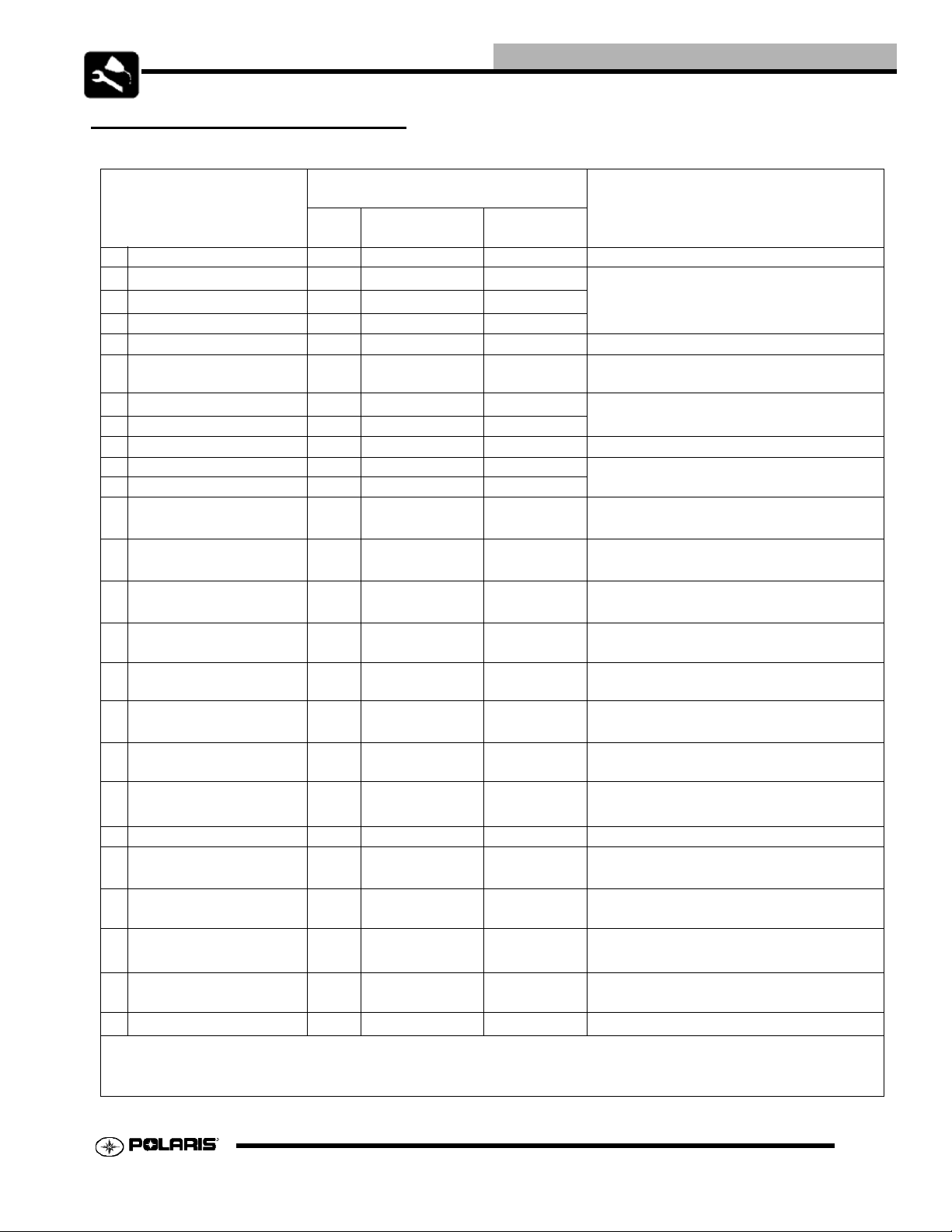
Periodic Maintenance Chart
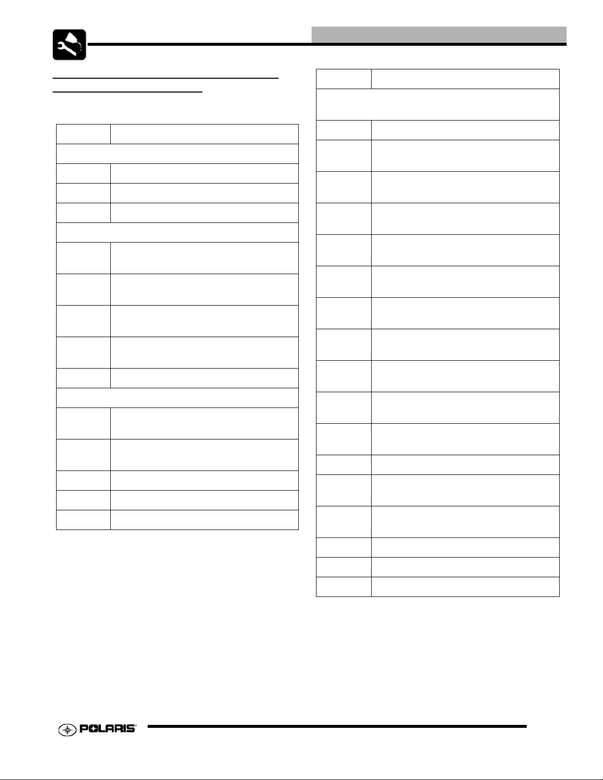
Item Maintenance Interval
(whichever comes first)
Hours Calendar Miles
(KM)
Steering - Pre-Ride - Check for free operation.
Front-suspension - Pre-Ride -
Rear-suspension - Pre-Ride -
Tires - Pre-Ride Engine Stop Switch - Check Operation
Brake fluid level - Pre-Ride -
Brake lever travel - Pre-Ride -
Brake systems - Pre-Ride Throttle - Pre-Ride - Check Operation
Wheels /fasteners - Pre-Ride Frame Fasteners - Pre-Ride -
Engine oil level - Pre-Ride -
E
Air filter, pre-filter - Daily - Inspect;clean often
E
Air box sediment tube - Daily - Drain deposits when visible
E
Coolant
(if applicable)
Headlamp/tail lamp - Daily Air filter,
main element
E
Recoil housing
(if equipped)
Brake pad wear 10 H Monthly 100 (160) Inspect periodically
Battery 20 H Monthly 200 (320) Check terminals; clean; test
Engine oil change
(break-in)
E
Front gearcase oil (if
equipped)
Middle gearcase oil (if
equipped)
Rear gearcase oil
(if equipped)
Transmission oil 25 H Monthly 250 (400) Inspect level; change yearly
- Daily -
- Weekly - Inspect; replace as needed
-Weekly -
20 H 1M 10 0 (1 60 )
25 H Monthly 250 (400) Inspect level; change yearly
25 H Monthly 250 (400) Inspect level; change yearly
25 H Monthly 250 (400) Inspect level; change yearly
Make adjustments as needed. See PreRide Checklist on Page 2.8.
Make adjustments as needed. See PreRide Checklist on Page 2.8
Make adjustments as needed. See PreRide Checklist on Page 2.8
Make adjustments as needed. See PreRide Checklist on Page 2.8
Make adjustments as needed. See PreRide Checklist on Page 2.8
Check level daily, change coolant every 2
years
Check operation; apply dielectric grease if
replacing
Drain water as needed, check often if
operating in wet conditions
Perform a break-in oil change at one
month
Perform these procedures more often for vehicles subjected to severe use.
E Emission Control System Service (California)
Have an authorized Polaris dealer perform these services.
MAINTENANCE
Remarks
2.3
Page 16
MAINTENANCE
Item Maintenance Interval
(whichever comes first)
Hours Calendar Miles
(KM)
Engine breather
filter (if equipped)
E
Engine breather
hose
General
lubrication
Shift Linkage 50 H 6 M 500 (800) Inspect, lubricate, adjust
Steering 50 H 6 M 500 (800) Inspect daily, Lubricate
Front suspension 50 H 6 M 500 (800)
Rear suspension 50 H 6 M 500 (800)
Carburetor float
bowl
Throttle Cable/
E
ETC Switch
Choke cable 50 H 6 M 500 (800)
E
Carburetor air
E
intake ducts/flange
Drive belt 100 H 12 M 1000 (1600) Inspect; adjust; replace as needed
Cooling system
(if applicable)
Engine oil change
*Severe Duty
E
**Normal Duty
Engine oil change
*Severe Duty
25 H Monthly 250 (400) Inspect; replace if necessary
100 H 6 M 1000 (1600) Inspect
50 H 3 M 500 (800)
50 H 6 M 500 (800)
50 H 6 M 500 (800)
50 H 6 M 500 (800)
50 H 6 M 500 (800)
500
25 H
50 H
25 H
6 M
12 M
6 M
(800)
1000
(1600)
500
(800)
Lubricate all grease fittings, pivots,
cables, etc.
Inspect, Lubricate, Tighten
Fasteners
Inspect, Lubricate, Tighten
Fasteners
Drain bowl periodically and prior to
storage
Inspect; adjust; lubricate; replace if
necessary
Inspect; adjust; lubricate; replace if
necessary
Inspect ducts for proper sealing/air
leaks
Inspect coolant strength seasonally;
pressure test system yearly
Perform a break-in oil change at 20
hours/one month, change more
frequently during cold weather
Replace at oil change
Remarks
**Normal Duty
Oil filter change 100 H 6 M 1000 (1600) Replace with oil change
E
Valve clearance 100 H 12 M 1000 (1600) Inspect; adjust
E
Perform these procedures more often for vehicles subjected to severe use.
E Emission Control System Service (California)
Have an authorized Polaris dealer perform these services
50 H
12 M
1000
(1600)
2.4
Page 17
MAINTENANCE
Item Maintenance Interval
(whichever comes first)
Hours Calendar Miles
(Km)
Fuel system 100 H 12M
E
Fuel Filter 100 H 12M
E
Radiator
(if applicable)
Cooling hoses
(if applicable)
Engine mounts 100 H 12M
Exhaust muffler /
pipe
Spark plug 100 H 12M
E
Ignition Timing 100 H 12M
E
Wiring 100 H 12M
Clutches (drive
and driven)
Front wheel
bearings
Brake fluid 200 H 24M
Spark arrestor 300 H 36M
E Idle Speed - Adjust as needed
Toe adjustment - Inspect periodica lly; adjust when part s are replaced
Auxiliary brake Pre- Ride Inspect daily; adjust as needed
Headlight aim - Adjust as needed
Perform these procedures more often for vehicles subjected to severe use.
E Emission Control System Service (California)
Have an authorized Polaris dealer perform these services.
100 H 12M
100 H 12M
100 H 12M
100 H 12M
100 H 12M
1000
(1600)
1000
(1600)
1000
(1600)
1000
(1600)
1000
(1600)
1000
(1600)
1000
(1600)
1000
(1600)
1000
(1600)
1000
(1600)
1000
(1600)
2000
(3200)
3000
(4800)
Check for leaks at tank cap, lines, fuel valve, filter,
pump, carburetor, replace lines every two years
Replace yearly
Inspect; clean external surfaces
Inspect for leaks
Inspect
Inspect
Inspect; replace as needed
Inspect
Inspect for wear, routing, security; apply die lectric
grease to connectors subjected to water, mud, etc.
Inspect;clean; replace worn parts
Inspect; replace as needed
Change every two years
Clean out
Remarks
2.5
Page 18
MAINTENANCE
LUBRICANTS / FLUIDS
POLARIS LUBES/FLUIDS
ATV Angle Drive Fluid
0W/40
2874865 - Quarts
2874867 - 55 Gallon Drum
2.6
Page 19
MAINTENANCE
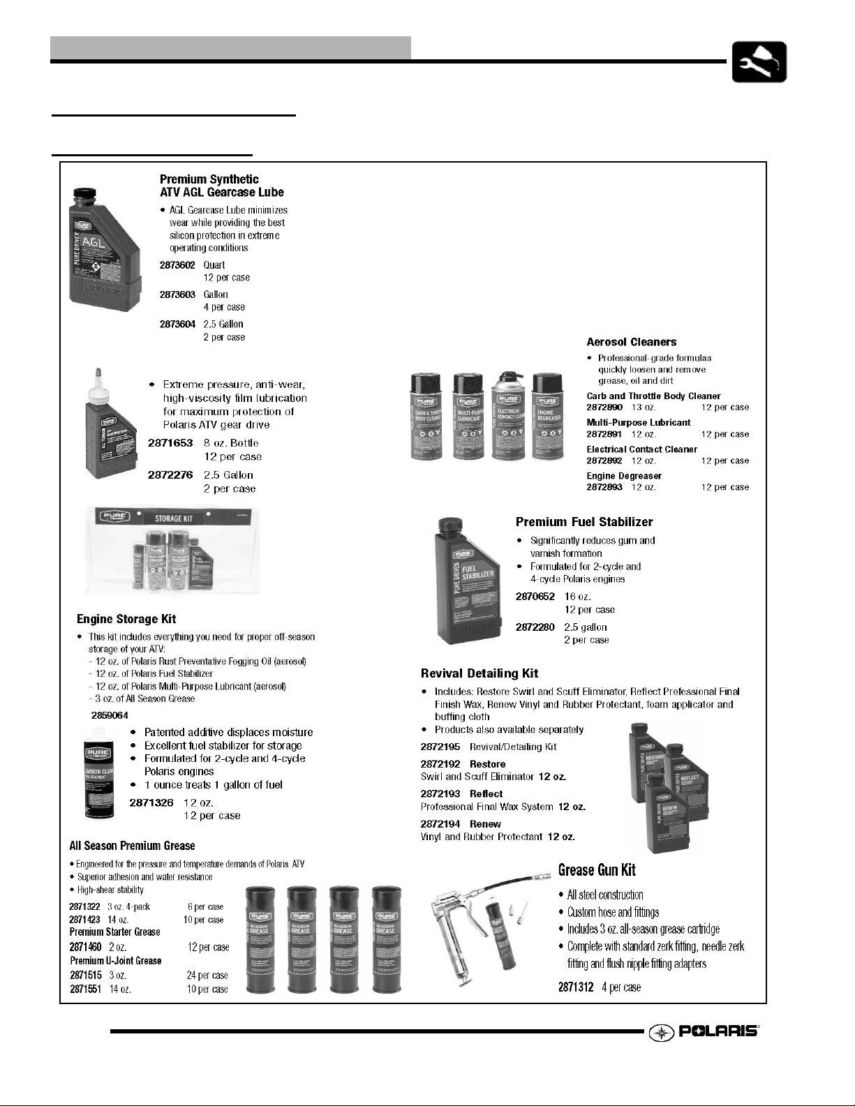
POLARIS LUBRICANTS,MAINTENANCE AND SERVICE PRODUCTS
Part No. Description
Engine Lubricant
2870791 Fogging Oil (12 oz. Aerosol)
2874865 0W-50 Quarts
2874867 0W-50 55 Gallon Drum
Gearcase / Tra nsmission Lubricants
2873602
2873603
2871653
2872276
2870465 Oil Pump for 1 Gallon Jug
2871322
2871423
2871460 Starter Drive Grease (12 Count)
2871312 Grease Gun Kit
2871329 Dielectric Grease (Nyogel™)
Premium Synthetic AGL Gearcase Lube
(12 oz. bottle) (12 Count)
Premium Synthetic AGL Gearcase Lube
(1 Gal.) (4 Count)
Premium ATV Angle Drive Fluid
(8 oz.) (12 Count)
Premium ATV Angle Drive Fluid
(2.5 Gal) (2 Count)
Grease / Specialized Lubricants
Premium All Season Grease
(3 oz. cartridge) (24 Count)
Premium All Season Grease
(14 oz. cartridge) (10 Count)
Part No. Description
Additives / Sealants / Thread Locking Agents /
Misc.
2870585 Loctite™ Primer N, Aerosol, 25 g
2871956
2871949
2871950
2871951
2871952
2871953
2871954
2870584
2870587
2871326
2870652 Fuel Stabilizer (16 oz.) (12 Count)
2871957
2871958
Loctite™ Thread Sealant 565
(50 ml.) (6 Count)
Loctite™ Threadlock 242
(50 ml.) (10 Count)
Loctite™ Threadlock 242
(6 ml.) (12 Count)
Loctite™ Threadlock 262
(50 ml.) (10 Count)
Loctite™ Threadlock 262
(6 ml.) (12 Count)
Loctite™ Threadlock 271
(6 ml.) (12 Count)
Loctite™ Threadlock 271
(36 ml.) (6 Count)
Loctite™ 680-Retaining Compound
(10 ml.)
Loctite™ 518 Gasket Eliminator / Flang e
Sealant (50 ml.) (10 Count)
Premium Carbon Clean
(12 oz.) (12 Count)
Black RTV Silicone Sealer
(3 oz. tube) (12 Count)
Black RTV Silicone Sealer
(11 oz. cartridge) (12 Count)
NOTE: Each item can be purchased separately at your
local Polaris dealer.
2870990 DOT3 Brake Fluid (12 Count)
2871557 Crankcase Sealant, 3-Bond 1215 (5oz.)
2872893 Engine Degreaser (12oz.) (12 Count)
NOTE: The number count indicated by each part number
in the table above indicates the number of units that are
shipped with each order.
2.7
Page 20
MAINTENANCE
POLARIS LUBRICANT SYMBOL IDENTIFICATION
NOTE: The symbols are used to properly identify the correct lube or grease to use in the maintenance section.
Polaris DOT 3
Brake Fluid
Polaris Synthetic
Gearcase Lube
Polaris Synthetic
OW-50 Oil
Polaris All Season Grease
Polaris ATV
Angle Drive Fluid
VEHICLE INSPECTION / MAINTENANCE
PRE-RIDE / DAILY INSPECTION
Perform the following pre-ride inspection daily, and when servicing the vehicle at each scheduled maintenance.
• Tires - check condition and pressures
• Fuel and oil - fill both to their proper level; Do not overfill
• All brakes - check operation(includes auxiliary brake)
• Throttle - check for free operation
• Headlight/Taillight/Brakelight - check operation of all indicator lights and switches
• Engine stop switch - check for proper function
• Wheels - check for loose wheel nuts
• Air cleaner element - check for dirt or water; clean or replace
• Steering - check for free operation, noting any unusual looseness in any area
• Loose parts - visually inspect vehicle for any damaged or loose nuts, bolts or fasteners
• Engine coolant(if applicable) - check for proper level at the recovery bottle
2.8
Page 21
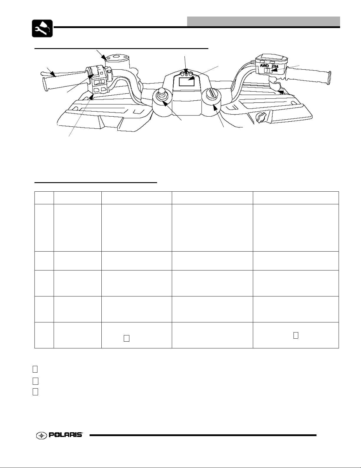
HAWKEYE HANDLEBAR COMPONENT LOCATIONS
4x4 switch
Indicator Lights
Front Brake
Speedo
MAINTENANCE
(if applicable)
Light Control
& Run Switch
Choke
Ignition/S tart Key
Reverse
Override
MAINTENANCE QUICK REFERENCE
III. # Item Lube Rec. Method Frequency*
Change after 1st month (25
hours), 50 hours thereafter;
1
2 Transmission
Engine Oil Polaris 0W-50
Synthetic
Polaris AGL
Lubricant
Add oil to proper level.
See procedure. Change annually2
Change more often (25 hours)
in severe duty conditions, or
short trip cold weather
operation.
Throttle
3Brake Fluid
4
5
* More often under severe use, such as operated in water or under severe loads.
1 Semi-annually or 50 hours of operation (refer to Maintenance Schedule for additional information)
2 Annually or 100 hours of operation (refer to Maintenance Schedule for additional information)
3 Grease conforming to NLGI No. 2, such as Polaris Premium All Season Grease, Conoco Superlube M or Mobilegrease Special.
Rear
Gearcase
A-Arm
Bushings
Polaris DOT 3 Brake
Fluid
Polaris A TV Angle Drive
Fluid
Polaris All Season
Grease 3
Fill master cylinder reservoir
to indicated level inside
reservoir.
Drain and refill with premeasured amount of
lubricant.
Locate grease fitting on
swing arm and grease with
grease gun.
As required. Change fluid
every 2 years.
As required*
Semi-annually 1
2.9
Page 22
MAINTENANCE
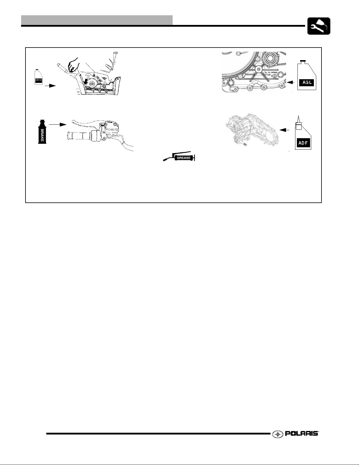
NOTE: Refer to Page 2.6-2.8 for the Polaris Lubricant Identification table.
1. Engine Oil
Reservoir Level
3. Brake Fluid
5. Bottom Rear Lower Control Arm
Lower Rear Bearing Carrier Pivot
Prop Shaft
2. Transmission Oil
4. Rear Gearcase Oil
2.10
Page 23
MAINTENANCE
TRANSMISSION LUBRICATION
The transmission lubricant level should be checked and
changed in accordance with the maintenance schedule.
• Be sure vehicle is level before proceeding.
• Check vent hose to be sure it is routed properly and
unobstructed.
TRANSMISSION SPECIFICATIONS
Specified Lubricant:
Polaris AGSL Gearcase Lubricant:
(PN 2873603) (Gallon) (PN 2873602) (12 oz.)
Capacity:
Even with fill plug
Drain Plug and Fill Plug Torque:
15 ft. lbs. (20 Nm)
To change / check transmission fluid:
1. Place a drain pan beneath oil pan and remove drain plug
from the crankcase. Allow oil to drain completely.
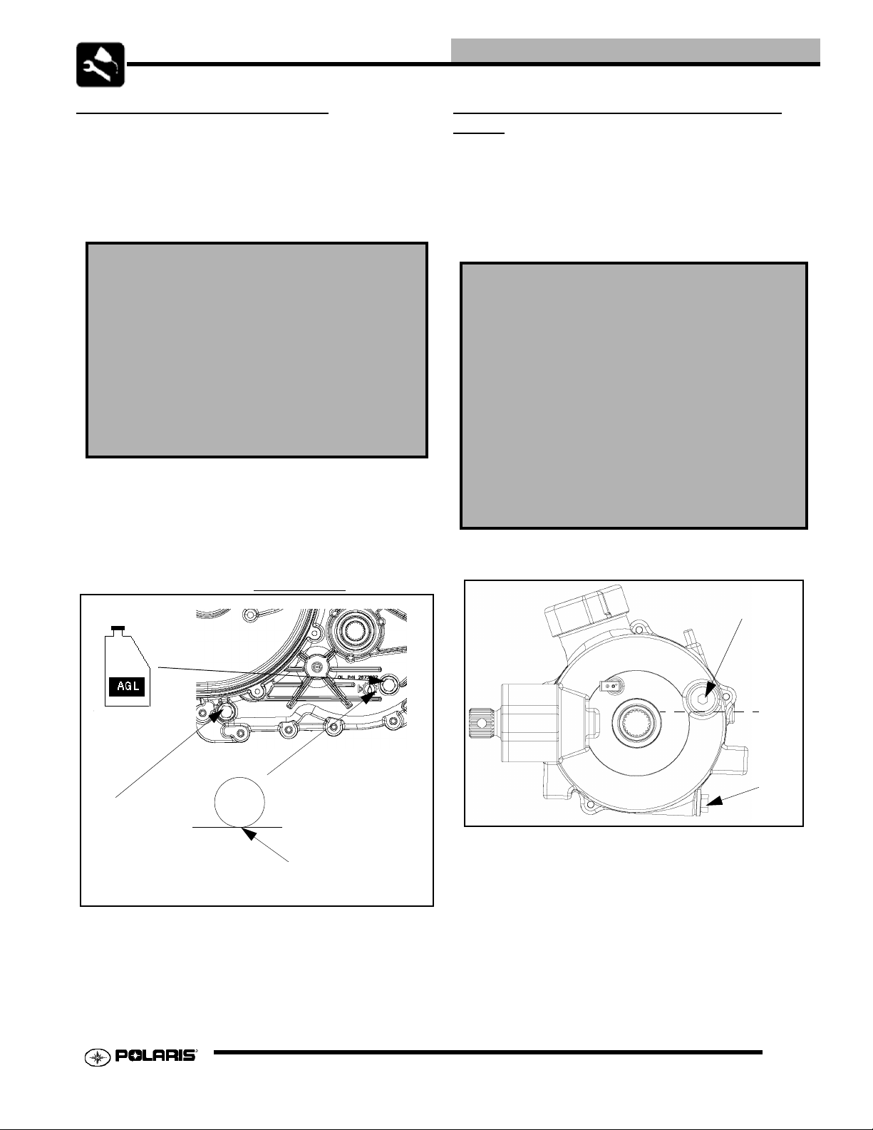
FRONT GEARCASE LUBRICATION (4X4 ONLY)
The front gearcase lubricant level should be checked and
changed in accordance with the maintenance schedule.
• Be sure vehicle is level before proceeding.
• Check vent hose to be sure it is routed properly and
unobstructed.
FRONT GEARCASE SPECIFICATIONS
Specified Lubricant:
Polaris Premium Demand Drive Hub Fluid:
(PN 2872277) (2.5 gallon) (PN 2871654) (8 oz.)
Capacity:
Even with fill plug
Drain Plug Torque:
8-10 ft. lbs. (11-13 Nm)
Fill / Check Plug Torque:
8-10 ft. lbs. (11-13 Nm)
2. Reinstall the drain pl ug . Tighten to specification.
3. Add the proper amount of lubricant to bring level into
operating range as shown. Do not over fill.
Drain Plug
Gearcase oil
flush with the bottom
of thread area.
4. Verify fluid level is correct and no leaks are present.
A
B
C
Oil Level Check
1. Position the vehicle on a level surface.
2. Remove the check/fill plug (A) and view the oil level. The
oil level should be at the bottom of the check plug (B)
threads.
3. Reinstall the check/fill plug (A). Torque to specification.
4. Reinstall the check plug (A) and a new sealing washer.
Torque to specification.
2.11
Page 24
MAINTENANCE
5. Check for leaks.
Oil Change
1. Remove the drain plug (C). Drain the oil into an appropriate
container. Discard used oil properly
2. Clean and reinstall the drain plug with a new sealing
washer. Torque to specification.
3. Remove the check plug (A).
4. Remove the fill plug (B) and add a pre-measured amount of
Polaris Angle Drive Fluid. The fluid should not be above
the bottom of the check plug (A) threads.
5. Reinstall the fill plug (B) and check plug (A). Torque to
specification.
6. Check for leaks.
LUBRICATION / GREASE POINTS
There are grease zerks rear lower control arm inner pivots,
lower rear bearing carrier pivots, and the prop shaft. Apply
grease until it is visible on the ends of the pivot points.
THROTTLE OPERATION - ALL MODELS
Check for smooth throttle opening and closing in all han dlebar
positions. Throttle lever operation should be smooth and lever
must return freely without binding.
1. Place the gear selector in neutral.
2. Set parking brake.
Verify free play of 1/16-3/16” (1.6-4.76 mm) and smooth
operation of choke cable.Adjustments to the freeplay can be
made by loosening the choke cable adjustment in or out to gain
the desired freeplay.
If smooth choke operation is not obtainable, inspect choke
cable for kinks or sharp bends in routing.
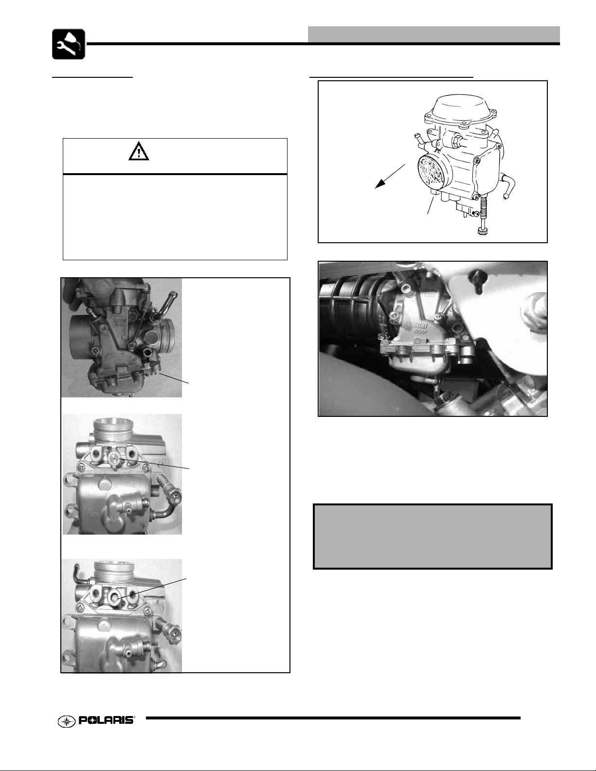
CARBURETOR DRAINING
The carburetor float bowl should be drained periodically to
remove moisture or sediment from the bowl, or before extended
periods of storage.
NOTE: The bowl drain screw is located on the bottom left
side of the float bowl.
1. Turn fuel valve to the OFF position.
2. Place a clean container beneath the bowl drain spigot or
bowl drain hose.
3. Turn drain screw out two turns and allow fuel in the float
bowl and fuel line to drain completely.
4. Inspect the drained fuel for water or sediment.
5. Tighten drain screw.
6. Turn fuel valve to “ON”.
7. Start machine and check for leaks.
NOTE: All tubes attached to the carburetor must be
check for pinching or blockage, as this will effect engine
performance
3. Start the engine and let it idle.
4. Turn handlebars from full right to full left. If idle speed
increases at any point in the turning range, inspect throttle
cable routing and condition. If cable is routed properly and
in good condition, repeat adjustment procedure.
5. Replace the throttle cable if worn, kinked, or damaged.
CHOKE (ENRICHER) ADJUSTMENT
CHOKE
2.12
Drain tube
attached
here
III. 1
Drain Screw
Page 25
MAINTENANCE
PILOT SCREW
The pilot system supplies fuel during en gine operatio n wi th the
throttle valve closed or slightly opened. The fuel/air mixture is
metered by pilot screw and discharged into the main bore
through the pilot outlet.
CAUTION
The pilot screw is calibrated at the factory to m eet
EPA / CARB regulations for air quality standards
and is sealed with a brass plug to prevent tampering. Removal of the tamper proof plug is not permitted. For service purposes, cleaning of the pilot
circuit can be done only by a certified repair shop to
ensure air quality standards are not exceeded.
PILOT SCREW ADJUSTMENT
FRONT
(Engine)
Pilot Screw
Pilot Screw Location
Brass Plug Installed
Brass Plug Removed
1. Start engine and warm it up to operating temperature (about
10 minutes).
2. Turn pilot screw in (clockwise) until lightly seated. Turn
screw out the specified number of turns. NOTE: Do not
tighten the pilot screw forcefully against the seat or the
screw and/or seat will be permanently damaged.
Pilot screws are calibrated at the factory. Each
carburetor has a slightly different pilot screw
setting. The specifications may require
additional tuning to achieve the desired results.
3. Connect an accurate tachometer that will read in increments
of + or - 50 RPM such as the PET 2100DX (PN
8712100DX) or the PET 2500 (PN 8712500).
4. Set idle speed to 1200 RPM. Always check throttle cable
freeplay after adjusting idle speed and adjust if necessary.
5. Slowly turn mixture screw clockwise using the pilot screw
wrench until engine begins to miss.
2.13
Page 26
MAINTENANCE
6. Slowly turn mixture screw counterclockwise until idle
speed increases to maximum RPM. Continue turning
counterclockwise until idle RPM begins to drop.
7. Center the pilot screw between the points in Step 5 and 6.
8. Re adjust idle speed if not within specification.
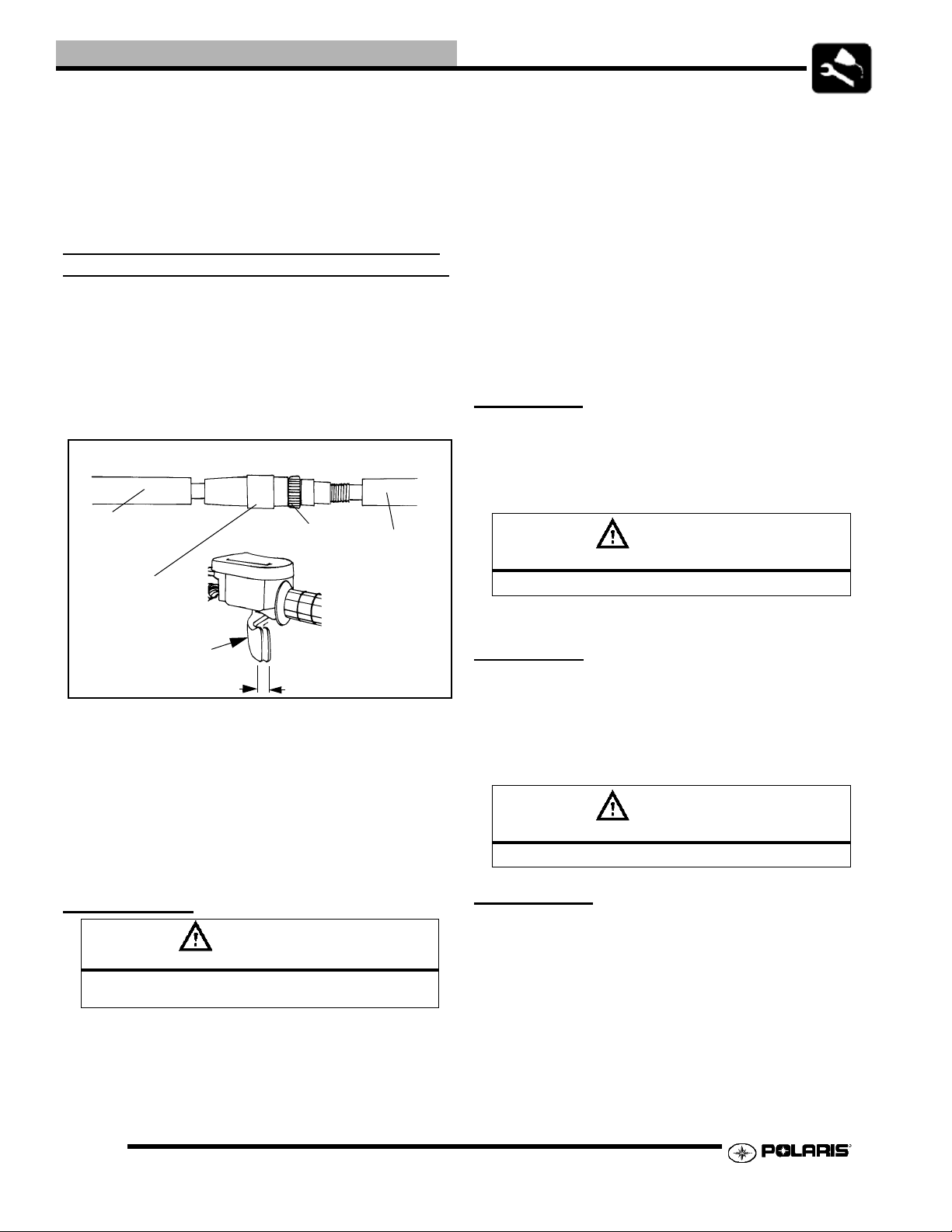
ELECTRONIC THROTTLE CONTROL (ETC SWITCH)/THROTTLE CABLE ADJUSTMENT
1. Slide the boots off inline cable adjuster sleeve. Loosen
adjuster locknut.
2. With handlebars centered and wheels pointing forward, turn
adjuster sleeve until 1/16” - 1/8” freeplay is achieved at the
thumb lever. After making any adjustment, “flip” the lever
slightly to confirm adjustment.
Boot
Adjuster
Sleeve
Locknut
Boot
• Do not overfill the tank. Do not fill the tank neck.
• If you get gasoline in your eyes or if you swallow
gasoline, seek medical attention immediately.
• If you spill gasoline on your skin or clothing,
immediately wash it off with soap and water and
change clothing.
• Never start the engine or let it run in an enclosed
area. Engine exhaust fumes are poisonous and can
result loss of consciousness or death in a short
time.
• Never drain the float bowl when the engine is hot.
Severe burns may result.
FUEL LINES
1. Check fuel lines for signs of wear, deterioration, damage, or
leakage. Replace if necessary.
2. Be sure fuel lines are routed properly and secured with
cable ties.
CAUTION
Make sure lines are not kinked or pinched
Direction
of travel
3. Tighten locknut and slide boots over cable adjuster until
they touch at the middle point of the adjuster.
4. With engine running, turn the handlebars from full left to
full right with transmission in neutral. Engine RPM should
not change and the engine should not die. If either of these
occur, return to the first step.
NOTE: If the throttle cable is adjusted too tight, the ETC
will limit operation at low throttle positions.
1/16” to 1/8”
Freeplay
FUEL SYSTEM
WARNING
Gasoline is extremely flammable and explosive
under certain conditions.
• Always stop the engine and refuel outdoors or in a
well ventilated area.
• Do not smoke or allow open flames or sparks in or
near the area where refueling is performed or
where gasoline is stored.
3. Replace all fuel lines every two years.
VENT LINES
1. Check fuel tank, crankcase, carburetor, battery and
transmission vent lines for signs of wear, deterioration,
damage or leakage. Replace every two years.
2. Verify vent lines are routed properly and secured with cable
ties.
CAUTION
Make sure lines are not kinked or pinched
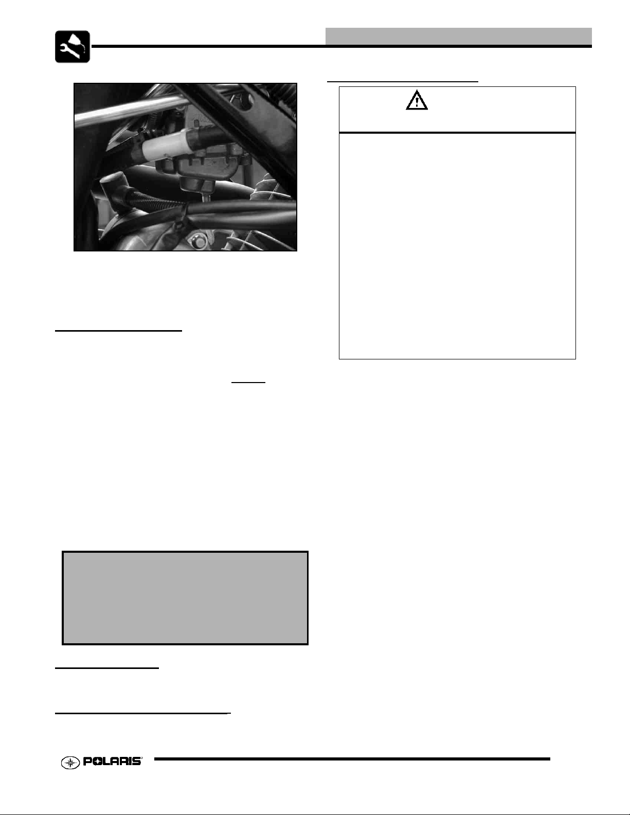
FUEL FILTER
The fuel filter should be replaced in accordance with the
Periodic Maintenance Chart. The fuel filter is located between
the fuel tank and carburetor.
1. Clamp fuel lines
2. Remove line clamps at both ends of the filter.
3. Remove fuel lines from filter.
4. Install new filter and clamps onto fuel lines with arrow
pointed in direction of fuel flow.
2.14
Page 27
MAINTENANCE
BATTERY MAINTENANCE
WARNING
Battery electrolyte is poisonous. It contains sulfuric
acid. Serious burns can result from contact with
skin, eyes or clothing. Antidote:
Fuel Filter
To Carburetor
5. Install clamps on fuel line.
6. Start engine and inspect for leaks.
7. Remove clamps
COMPRESSION TEST
NOTE: This 4-Stroke engine is equipped with an
automatic decompressor. Compression readings will vary
in proportion to cranking speed during the test. Average
compression (measured) is about 90 psi
compression test.
Smooth idle generally indicates good compression. Low engine
compression is rarely a factor in running condition problems
above idle speed. Abnormally high compression can be caused
by a decompressor malfunction, or worn or damaged exhaust
cam lobes. Inspect camshaft and automatic decompression
mechanism if compression is abnormally high.
A cylinder leakage test is the best indication of engine
condition on models with automatic decompression. Follow
tester manufacturer’s instructions to perform a cylinder leakage
test. (Never use high pressure leakage testers as crankshaft
seals may dislodge and leak).
Cylinder Compression
Standard: 90PSI
Cylinder Leakage
Service Limit: 10%
(Inspect for cause if leakage exceeds 10%)
during a
External: Flush with water.
Internal: Drink large quantities of water or milk. Fol-
low with milk of magnesia, beaten egg, or vegetable
oil. Call physician immediately.
Eyes: Flush with water for 15 minutes and get
prompt medical attention.
Batteries produce explosive gases. Keep sparks,
flame, cigarettes, etc. away. Ventilate when charging or using in an enclosed space. Always shield
eyes when working near batteries. KEEP OUT OF
REACH OF CHILDREN.
NOTE: All Hawkeye batteries are Low Maintenance
design and construction. All Low Maintenance
batteries are fully charged and tested at the factory
before installation. Expected shelf life is 6-8 months
depending on storage conditions. As a general rule
before placing the battery into service, check the
battery condition and charge accordingly.
Low Maintenance batteries are permanently sealed at the time
of manufacture. The use of lead-calcium and AGM technology
instead of lead-antimony allows the battery acid to be fully
absorbed. For this reason, a Low Maintenance battery case is
dark and the cell caps are not removable, since there is no need
to check electrolyte level.
NEVER attempt to add electrolyte or water to a Low
Maintenance battery. Doing so will damage the case and
shorten the life of the battery. Refer to the Battery Maintenance
Video (PN 9917987) for proper instruction on servicing Low
Maintenance batteries.
ENGINE MOUNTS
Inspect rubber engine mounts for cracks or damage.
ENGINE FASTENER TORQUE
Check engine fasteners and ensure they are tight
2.15
Page 28
MAINTENANCE
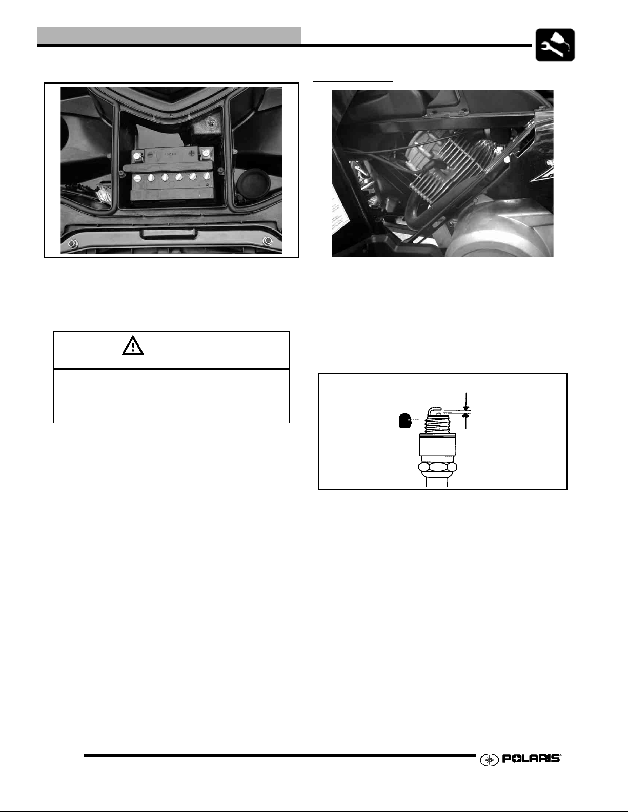
The battery is located under front rack.
To remove the battery:
1. Disconnect holder strap.
2. Disconnect battery negative (-) (black) cable first, followed
by the positive (+) (red) cable.
CAUTION
To reduce the chance of sparks: Whenever removing the battery, disconnect the negative
(black) cable first. When reinst alling the battery,
install the negative cable last.
SPARK PLUG
1. Remove the seat and left hand side panel.
2. Remove spark plug high tension lead. Clean plug area so no
dirt and debris can fall into engine when plug is removed.
3. Remove spark plug.
4. Inspect electrodes for wear and carbon buildup. Look for a
sharp outer edge with no rounding or erosion of the
electrodes.
Inspect electrode for wear and buildup
Spark Plug Gap
3. Remove the battery.
4. Clean battery cables and terminals with a stiff wire brush.
Corrosion can be removed using a solution of one cup water
and one tablespoon baking soda. Rinse well with clean
water and dry thoroughly.
5. Reinstall battery, attaching positive (+) (red) cable first and
then the negative (-) (black) cable.
6. Coat terminals and bolt threads with Dielectric Grease (PN
2871329).
7. Reinstall battery cover and holder strap.
5. Clean with electrical contact cleaner or a glass bead spark
plug cleaner only. CAUTION: A wire brush or coated
abrasive should not be used.
6. Measure gap with a wire gauge. Refer to specifications for
proper spark plug type and gap. Adjust gap if necessary by
bending the side electrode carefully.
7. If necessary, replace spark plug with proper type.
CAUTION: Severe engine damage may occur if the
incorrect spark plug is used.
8. Apply a small amount of anti-seize compound to the spark
plug threads.
9. Install spark plug and torque to 9-11 ft. lbs (12-14 Nm).
2.16
Page 29
MAINTENANCE
10. Replace side panel and seat.
Recommended Spark Plug:
NGK R7HSA
Spark Plug Torque: 9-11 Ft. Lbs.
(12 - 14 Nm)
IGNITION TIMING
Timing is CDI controlled and has no adjustment procedure.
Ignition Timing:
o
+ 2o BTDC@3000RPM
32
MAIN AIR FILTER CLEANING
It is advisable to replace the filter when it is dirty. However, in
an emergency it is permissible to clean the main filter if you
observe the following practices.
• Never immerse the filter in water since dirt can be
transferred to the clean air side of the filter.
• If compressed air is used never exceed a pressure
of 40 PSI. Always use a dispersion type nozzle to
prevent filter damage and clean from the inside to
the outside.
• Replace the air filter every 50 hours, and possibly
more often in very dirty conditions.
AIR FILTER/PRE-FILTER SERVICE
It is recommended that the air filter and pre filter be replaced
annually. When riding in extremely dusty conditions,
replacement is required more often.
The pre filter should be cleaned before each ride using the
following procedure:
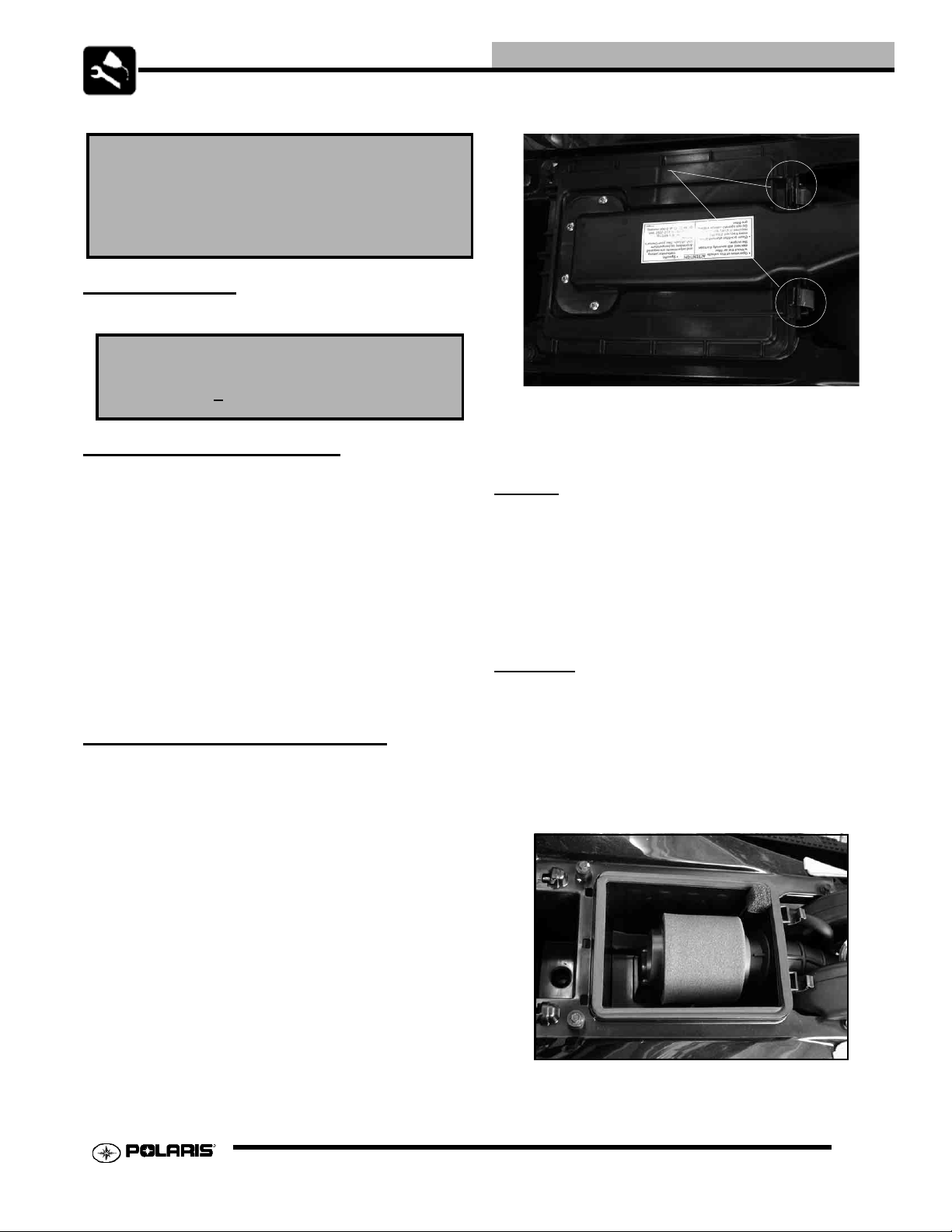
2. Remove clips from air box cover (A) and remove cover.
A
3. Inspect the gasket. It should adhere tightly to the cover and
seal all the way around.
4. Remove air filter assembly.
Cleaning:
5. Slip the pre-filter element off of main element. Clean the
pre filter with hot soapy water.
6. Rinse and dry thoroughly.
7. Inspect element for tears or damage.
8. Inspect main filter and replace if necessary. If the filter has
been soaked with fuel or oil it must be replaced.
Installation:
9. Reinstall pre-filter element over main filter. Be sure the
element covers entire surface of main filter without folds,
creases, or gaps.
10. Reinstall filter on main filter mount. Place filter clamp over
the assembly and tighten.
NOTE: Apply a small amount of general purpose grease
to the sealing edges of the filter before reinstalling.
1. Remove the seat.
2.17
Page 30
MAINTENANCE
Proper Filter Placement
Filter
Support
Air Box
Main Filter
CVT DRAIN PLUG & DRYING
NOTE: If operating the ATV through water, be sure to
check the CVT and other components for water ingestion.
The ATV should be checked immediately.
1. To release any water that maybe trapped in the CVT cover,
simply remove the CVT drain plug and O-ring located on
the bottom of the CVT cover and let the water drain out.
III. 3
NOTE: The air filter should rest on the filter support.
Proper placement of the air filter is important to prevent
rattles and air leaks. See Illustration above.
11. Install air box cover and secure with clips.
Rear
AIR BOX SEDIMENT TUBE
Periodically check the air box drain tube located toward the
rear of the machine. Drain whenever deposits are visible in the
clear tube.
Sediment Tube
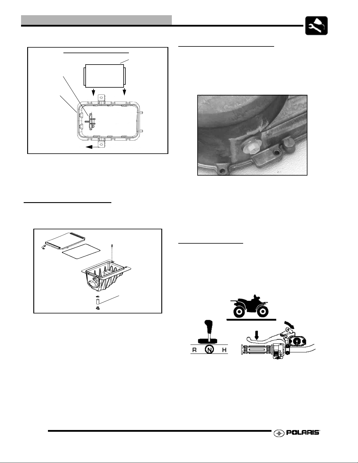
2. To further expel water from the cover and to dry out the
CVT system, shift the transmission to neutral and rev
engine slightly to expel the moisture and air-dry the belt and
clutches. Allow engine RPM to settle to idle speed, shift
transmission to lowest available range and test for belt
slippage. Operate ATV in lowest available range for a short
period of time until CVT system is dry.
ENGINE OIL LEVEL
To check the oil level:
1. Set machine on a level surface.
2. Place the transmission in neutral.
3. Lock the parking brake.
NOTE: The sediment tube will require more frequent
service if the vehicle is operated in wet conditions or at
high throttle openings for extended periods.
1. Remove drain plug from end of sediment tube.
2. Drain Tube.
3. Reinstall drain plug.
2.18
4. Start the engine. Allow it to idle for 30 seconds.
5. Turn the engine off.
6. The oil dipstick and fill hole are located behind the recoil on
Page 31

MAINTENANCE
the right side of the ATV.
7. Remove the dipstick and wipe it clean.
8. Reinstall the dipstick completely
9. Remove the dipstick an check the oil level.
10. Add oil as needed to bring the level between the minimum
and maximum marks. Do not over fill.
11. Reinstall the dipstick.
6. Clean the area around the drain plug.
CAUTION
Hot oil may result in serious burns. Do not allow hot oil
to contact skin.
7. Place a drain pan under the vehicle.
8. Remove the drain plug. Use a 6mm Allen wrench.
9. Drain the oil.
OIL AND FILTER CHANGE
1. Set machine on a level surface.
2. Place the transmission in neutral.
3. Lock the parking brake.
4. Start the engine. Allow it to idle for two to three minuets.
5. Turn the engine off.
10. Reinstall the drain plug with a new sealing washer.
11. Torque to 14 ft-lb (19Nm).
NOTE: The sealing surfaces on the drain plug and
crankcase should be clean and free of burrs , nicks o r
scratches.
12. Place towels under the oil filter.
13. Using an oil filter wrench, turn the filter counter clockwise
to remove it.
2.19
Page 32

MAINTENANCE
14. Clean the filter sealing area on the engine.
15. Lubricate the filter o-ring. Check to make sure the o-ring is
in good condition.
16. Install the new oil filter, After the filter contacts the engine
surface turn it 1/2 turn by hand.
VALVE CLEARANCE ADJUSTMENT
INTAKE VALVE CLEARANCE
1. Verify cam lobes are pointed down.
2. Insert a .006” (.15 mm) feeler gauge between end of intake
valve stem and adjuster screw.
3. When clearance is correct, hold adjuster screw and tighten
locknut securely.
4. Re-check the valve clearance.
17. Remove the dipstick.
18. Add 0W/50 oil.
19. Reinstall the dipstick.
20. Start the engine and allow it to idle for two minuets.
21. Turn off the engine. Check for oil leaks.
22. Check the oil level. Add oil as needed to bring the level
between the min. and max marks. Do not overfill.
5. Repeat adjustment procedure if necessary until clearance is
correct with locknut secured.
INTAKE/ EXHAUST VALVE CLEARANCE
.006” (.15 mm)
EXHAUST VALVE CLEARANCE
1. Verify cam lobes are pointed down.
2. Insert an .006” (.15 mm) feeler gauge between end of
exhaust valve stem and adjuster screw.
3. Loosen locknut and turn adjuster screw until there is a slight
drag on feeler gauge.
4. When clearance is correct, hold adjuster screw and tighten
locknut securely.
5. Re-check the valve clearance.
6. Repeat adjustment procedure if necessary until clearance is
correct with locknut secured.
STEERING
23. Discard used oil and filter properly.
2.20
The steering components should be checked periodically for
loose fasteners, worn tie rod ends, and damage. Also check to
make sure all cotter pins are in place. If cotter pins are
removed, they must not be re-used. Always use new cotter pins.
Page 33

MAINTENANCE
Replace any worn or damaged steering components. Steering
should move freely through entire range of travel without
binding. Check routing of all cables, hoses, and wiring to be
sure the steering mechanism is not restricted or limited. NOTE:
Whenever steering components are replaced, check front end
alignment. Use only genuine Polaris parts.
WARNING
Due to the critical nature of the procedures outlined in this
chapter, Polaris recommends steering component repair
and adjustment be performed by an authorized Polaris
Dealer. Only a qualified technician should replace worn or
damaged steering parts. Use only genuine Polaris
replacement parts.
One of two methods can be used to measure toe
alignment: The string method and the chalk method. If
adjustment is required, refer to following pages for
procedure.
TIE ROD END/STEERING INSPECTION
To check for play in the tie rod end, grasp the steering tie rod,
pull in all directions feeling for movement.
• Repeat inspection for inner tie rod end (on steering
post).
• Replace any worn steering components. Steering
should move freely through entire range of travel
without binding.
first, and then at front and rear. Try to move the wheel and
hub by pushing inward and pulling outward.
Check for Loose Wheel or Hub
• If abnormal movement is detected, inspect the hub
and wheel assembly to determine the cause.
CAMBER AND CASTER
The camber and caster are non-adjustable.
TOE ALIGNMENT
1. Place machine on a smooth level surface.
2. Set handlebars in a straight ahead position and secure
handlebars in this position. NOTE: The steering arm can be
used as an indicator of whether the handlebars are straight.
The arm should always point straight back from the steering
post.
• Elevate front end of machine so front wheels are off the
ground. Check for any looseness in front hub / wheel
assembly by grasping the tire firmly at top and bottom
3. Place a chalk mark on the center line of the front tires
approximately 10” (25.4 cm) from the floor or as close to
the hub/axle center line as possible. NOTE: It is important
that the height of both marks be equally positioned in order
to get an accurate measurement.
4. Measure the distance between the marks and record the
measurement. Call this measurement “A”.
o
5. Rotate the tires 180
backward. Position chalk marks facing rearward, even with
the hub/axle centerline.
6. Again measure the distance between the marks and record.
Call this measurement “B”. Subtract measurement “B”
from measurement “A”. The difference between
measurements “A” and “B” is the vehicle toe alignment.
The recommended vehicle toe tolerance is 1/8” to 1/4” (.3
to.6 cm) toe out. This means the measurement at the front
of the tire (A) is 1/8” to 1/4” (.3 to.6 cm) wider than the
by moving vehicle forward or
2.21
Page 34

MAINTENANCE
measurement at the rear (B).
Chalk Line
Measurement
“A”
Measurement “B”
TOE ALIGNMENT ADJUSTMENT
If toe alignment is incorrect, measure the distance between
vehicle center and each wheel. This will tell you which tie rod
needs adjusting. NOTE: Be sure handlebars are straight ahead
before determining which tie rod(s) need adjustment.
CAUTION
During tie rod adjustment, it is very important that
the following precautions be taken when tightening
tie rod end jam nuts. If the rod end is positioned incorrectly it will not pivot, and may break
To adjust toe alignment:
• Hold tie rod end to keep it from rotating.
• Loosen jam nuts at both end of the tie rod.
• Shorten or lengthen the tie rod until alignment is as
required to achieve the proper toe setting - (1/8” to
1/4”).
• Important: When tightening the tie rod end jam
nuts, the rod ends must be held parallel to prevent
rod end damage and premature wear. Damage
may not be immediately apparent if done
incorrectly. See illustration.
Hold
Rod End
Correctly
Tightened
Jam Nut
Incorrectly
Tightened
Jam Nut
EXHAUST CLEANING
WARNING
• Do not perform clean out immediately after
the engine has been run, as the exhaust
system becomes very hot. Serious burns
could result from contact with exhaust
components.
• To reduce fire hazard, make sure that there
are no combustible materials in the area
when purging the spark arrestor.
• Wear eye protection.
• Do not stand behind or in front of the vehicle
while purging the carbon from the spark
arrestor.
• Never run the engine in an enclosed
area.Exhaust contains poisonous carbon
monoxide gas.
• Do not go under the machine while it is
inclined.Set the hand brake and block the
wheels to prevent roll back.
2.22
Failure to heed these warnings could result in serious
personal injury or death.
The exhaust pipe must be periodically purged of accumulated
carbon as follows:
1. Allow the muffler to cool if hot.
2. Remove the fastener (1) and remove the arrestor from the
Page 35

MAINTENANCE
end of the muffler.
1
Arrestor
3. Use a non-synthetic brush to clean the arrestor screen. A
synthetic brush may melt if components are warm. If
necessary, blow debris from the screen with compressed
air.
4. Inspect the screen for wear and damage. Replace if
necessary.
5. Remove and inspect the gasket. Replace if worn or
damaged.
6. Reinstall the gasket and arrestor.
• Use Polaris DOT 3 or DOT 4 Brake Fluid
• Check brake system for fluid leaks, excessive
travel or spongy feel.
• Check brake pads for wear, damage or looseness.
• Check surface condition of the disc.
• Inspect thickness of brake pad friction material.
SIGHT GLASS
BRAKE PAD INSPECTION
Front Brake Pads
7. Use a wire brush to clean the arrestor screen. (NOTE: A
synthetic brush may melt if components are warm.) If
necessary, blow debris from the screen with compressed
air.
8. Reinstall the clean out plug and arrestor.
9. Torque screws to 50 in. lbs. (5.6 Nm).
BRAKE SYSTEM INSPECTION
The following checks are recommended to keep the brake
system in good operating condition. Service life of brake
system components depends on operating conditions. Inspect
brakes in accordance with the maintenance schedule and before
each ride.
• Keep fluid level in the master cylinder reservoir to
the indicated level inside reservoir.
• Check the fluid level “eye”. If it is clear, it is an
indication that fluid is needed or the brake pads may
be worn, which can reduce the fluid level.
Brake Pad
Service Limit - .059” (1.5 mm)
Brake pads should be changed when friction material is worn to
.59” (1.5 mm).
Measure
Thickness
HOSE/FITTING INSPECTION
Check brake system hoses and fittings for cracks, deterioration,
abrasion, and leaks.Tighten any loose fittings and replace any
worn or damaged parts.
BRAKE FREEPLAY
Hand Brake Lever
1. Check the brake lever, and foot brake for loose connections,
free play, and damage.
2. Measure the hand brake lever freeplay. Freeplay should be
2.23
Page 36

MAINTENANCE
0.40-0.80 in. (10-20 mm).
3. If excessive free play exists, inspect brake pads, pedal,
linkage springs, and hoses for wear or damage and replace
any parts as needed.
.40” - .80”
(10-20 mm)
Hand Brake Lever Free Play
Rear Foot Brake
• If free play is excessive: Inspect brake pads, pedal,
linkage springs, and hoses for wear or damage and
replace any parts as needed.
SUSPENSION SPRING FRONT / REAR PRELOAD ADJUSTMENT
Operator weight and vehicle loading affect suspension spring
preload requirements. Using Spanner Wrench (PN 2870872)
adjust as necessary to avoid bottoming of the shocks.
Rear Brake
4. Check foot brake effectiveness by applying approximately
50 lb. (23 kg) downward force on the pedal. The top of the
pedal should travel not more than 1 inch (25.4mm).
50 lbs
5. If more than one inch, two things must be examined:
• Free play of the brake pedal should be 1/8 - 1/4
inch (3.2 - 6.35 mm).
1” or greater
Floorboard
2.24
Page 37

MAINTENANCE
FRONT SUSPENSION INSPECTION
Compress and release front suspension. Damping should
be smooth throughout the range of travel.
Check all front suspension components for wear or damage.
Inspect front shocks for leakage.
REAR SUSPENSION INSPECTION
Compress and release rear suspension. Damping should
be smooth throughout the range of travel.
• Check all rear suspension components for wear or
damage.
• Inspect shock for leakage.
Shock Spanner Wrench
(PN 2870872)
CONTROLS
Check controls for proper operation, positioning and
adjustment.
WHEEL REMOVAL/INSTALL- FRONT OR REAR
Wheel Removal
1. Stop the engine, place the transmission in gear and lock the
parking brake.
2. Loosen the wheel nuts slightly.
3. Elevate the side of the vehicle by placing a suitable stand
under the footrest frame.
4. Remove the wheel nuts and remove the wheel.
Wheel Installation
1. With the transmission in gear and the parking brake locked,
place the wheel in the correct position on the wheel hub. Be
sure the valve stem is toward the outside and rotation
arrows on the tire point toward forward rotation.
NOTE:Apply an anti-seize compound on the front
wheel spindle before hub/wheel installation.
2. Attach the wheel nuts and finger tighten them.
3. Lower the vehicle to the ground.
4. Securely tighten the wheel nuts to the proper torque listed
in the table.
CAUTION
• Brake control and switch must be positioned to
allow brake lever to travel throughout entire range
without contacting switch body.
WHEELS
Inspect all wheels for runout or damage. Check wheel nuts and
ensure they are tight. Do not over tighten the wheel nuts.
WHEEL, HUB, AND SPINDLE TORQUE TABLE
Item Specification
Front Wheel Nuts 27 Ft. Lbs. (37Nm)
Rear Wheel Nuts 27 Ft. Lbs. (37Nm)
Hub Retaining Nut 80 Ft. Lbs. (108 Nm)
Improperly installed wheels could affect vehicle
handling and tire wear. On vehicles with tapered
rear wheel nuts, make sure t apered end of nut g oes
into taper on wheel.
Wheel
Wheel Nuts (4)
27 ft. lbs. (37 Nm)
Cotter
Key
Hub Retaining Nut
80 ft. lbs. (108 Nm)
2.25
Page 38

MAINTENANCE
WHEEL INSTALLATION
1. With the transmission in gear and the parking brake locked,
place the wheel in the correct position on the wheel hub. Be
sure the valve stem is toward the outside and rotation
arrows on the tire point toward forward rotation.
2. Attach the wheel nuts and finger tighten them.
3. Lower the vehicle to the ground.
4. Securely tighten the wheel nuts to the proper torque listed
in the table.
CAUTION
If wheels are improperly installed it could affect
vehicle handling and tire wear. Be sure to properly torque and install all wheel nuts.
TIRE PRESSURE
Tire Pressure Inspection (PSI - Cold)
Front Rear
Tire Tread Depth
Always replace tires when tread depth is worn to 1/8” (3 mm)
or less.
Tread
Depth 1/8” (3 mm)
FRAME, NUTS, BOLTS, FASTENERS
Periodically inspect the torque of all fasteners in accordance
with the maintenance schedule. Check that all cotter pins are in
place. Refer to specific fastener torques listed in each chapter.
44
TIRE INSPECTION
WARNING
Operating an ATV with worn tires will increase the
possibility of the vehicle skidding and possible loss
of control.
Worn tires can cause an accident.
Always replace tires when the tread depth mea-
sures 1/8” (.3 cm) or less.
CAUTION
• Maintain proper tire pressure. Refer to the
warning tire pressure decal applied to the
vehicle.
• Improper tire inflation may affect ATV
maneuverability.
2.26
• When replacing a tire always use original
equipment size and type.
• The use of non-standard size or type tires
may affect ATV handling.
Page 39

ENGINE
CHAPTER 3
ENGINE
TOOLS. . . . . . . . . . . . . . . . . . . . . . . . . . . . . . . . . . . . . . . . . . . . . . . . . . . . . . . . . . . . . . 3.2
SPECIAL TOOLS . . . . . . . . . . . . . . . . . . . . . . . . . . . . . . . . . . . . . . . . . . . . . . . . . . . . . . .3.2
TORQUE SPECIFICATIONS. . . . . . . . . . . . . . . . . . . . . . . . . . . . . . . . . . . . . . . . . . . . . 3.2
ENGINE TORQUE SPECIFICATIONS. . . . . . . . . . . . . . . . . . . . . . . . . . . . . . . . . . . . . . .3.2
TORQUE PATTERNS . . . . . . . . . . . . . . . . . . . . . . . . . . . . . . . . . . . . . . . . . . . . . . . . . . .3.4
GENERAL ENGINE SERVICE . . . . . . . . . . . . . . . . . . . . . . . . . . . . . . . . . . . . . . . . . . . 3.5
ENGINE EXPLODED VIEW . . . . . . . . . . . . . . . . . . . . . . . . . . . . . . . . . . . . . . . . . . . . . . .3.5
ENGINE SERVICE DATA. . . . . . . . . . . . . . . . . . . . . . . . . . . . . . . . . . . . . . . . . . . . . . . . .3.6
ENGINE SERVICE DATA. . . . . . . . . . . . . . . . . . . . . . . . . . . . . . . . . . . . . . . . . . . . . . . . .3.7
OIL FLOW DIAGRAM. . . . . . . . . . . . . . . . . . . . . . . . . . . . . . . . . . . . . . . . . . . . . . . . . . . .3.9
PISTON IDENTIFICATION . . . . . . . . . . . . . . . . . . . . . . . . . . . . . . . . . . . . . . . . . . . . . . .3.10
PISTON RING IDENTIFICATION. . . . . . . . . . . . . . . . . . . . . . . . . . . . . . . . . . . . . . . . . .3.10
ACCESSIBLE COMPONENTS. . . . . . . . . . . . . . . . . . . . . . . . . . . . . . . . . . . . . . . . . . . .3.10
ENGINE SERVICE . . . . . . . . . . . . . . . . . . . . . . . . . . . . . . . . . . . . . . . . . . . . . . . . . . . 3.10
ENGINE REMOVAL . . . . . . . . . . . . . . . . . . . . . . . . . . . . . . . . . . . . . . . . . . . . . . . . . . . .3.10
ENGINE INSTALLATION NOTES . . . . . . . . . . . . . . . . . . . . . . . . . . . . . . . . . . . . . . . . .3.13
TRANSMISSION REMOVAL . . . . . . . . . . . . . . . . . . . . . . . . . . . . . . . . . . . . . . . . . . . . .3.14
TRANSMISSION INSTALLATION NOTES. . . . . . . . . . . . . . . . . . . . . . . . . . . . . . . . . . .3.15
ENGINE LUBRICATION. . . . . . . . . . . . . . . . . . . . . . . . . . . . . . . . . . . . . . . . . . . . . . . . .3.16
OIL FLOW / PRESSURE TEST . . . . . . . . . . . . . . . . . . . . . . . . . . . . . . . . . . . . . . . . . . .3.16
ENGINE BREATHER / OIL SEPARATOR . . . . . . . . . . . . . . . . . . . . . . . . . . . . . . . . . . .3.16
CAM CHAIN TENSIONER REMOVAL. . . . . . . . . . . . . . . . . . . . . . . . . . . . . . . . . . . . . .3.16
CAM CHAIN TENSIONER INSPECTION. . . . . . . . . . . . . . . . . . . . . . . . . . . . . . . . . . . .3.17
ROCKER ARM/SHAFT DISASSEMBLY AND INSPECTION. . . . . . . . . . . . . . . . . . . . .3.17
CAMSHAFT REMOVAL AND INSPECTION . . . . . . . . . . . . . . . . . . . . . . . . . . . . . . . . .3.18
CAMSHAFT INSPECTION. . . . . . . . . . . . . . . . . . . . . . . . . . . . . . . . . . . . . . . . . . . . . . .3.19
CYLINDER HEAD REMOVAL . . . . . . . . . . . . . . . . . . . . . . . . . . . . . . . . . . . . . . . . . . . .3.19
CYLINDER HEAD INSPECTION . . . . . . . . . . . . . . . . . . . . . . . . . . . . . . . . . . . . . . . . . .3.19
CYLINDER HEAD WARP INSPECTION . . . . . . . . . . . . . . . . . . . . . . . . . . . . . . . . . . . .3.20
COMBUSTION CHAMBER INSPECTION . . . . . . . . . . . . . . . . . . . . . . . . . . . . . . . . . . .3.20
CYLINDER HEAD DISASSEMBLY . . . . . . . . . . . . . . . . . . . . . . . . . . . . . . . . . . . . . . . .3.20
VALVE INSPECTION. . . . . . . . . . . . . . . . . . . . . . . . . . . . . . . . . . . . . . . . . . . . . . . . . . .3.21
VALVE SEAT RECONDITIONING . . . . . . . . . . . . . . . . . . . . . . . . . . . . . . . . . . . . . . . . .3.21
CYLINDER HEAD ASSEMBLY . . . . . . . . . . . . . . . . . . . . . . . . . . . . . . . . . . . . . . . . . . .3.24
VALVE SEALING TEST . . . . . . . . . . . . . . . . . . . . . . . . . . . . . . . . . . . . . . . . . . . . . . . . .3.24
ENGINE BOTTOM END DISASSEMBLY. . . . . . . . . . . . . . . . . . . . . . . . . . . . . . . . . . . .3.25
CAM CHAIN GUIDE AND TESIONER BLADE. . . . . . . . . . . . . . . . . . . . . . . . . . . . . . . .3.25
PISTON REMOVAL . . . . . . . . . . . . . . . . . . . . . . . . . . . . . . . . . . . . . . . . . . . . . . . . . . . .3.25
CYLINDER INSPECTION. . . . . . . . . . . . . . . . . . . . . . . . . . . . . . . . . . . . . . . . . . . . . . . .3.26
CYLINDER HONE SELECTION/ HONING PROCEDURE. . . . . . . . . . . . . . . . . . . . . . .3.26
HONING TO DEGLAZE . . . . . . . . . . . . . . . . . . . . . . . . . . . . . . . . . . . . . . . . . . . . . . . . .3.26
PISTON INSPECTION . . . . . . . . . . . . . . . . . . . . . . . . . . . . . . . . . . . . . . . . . . . . . . . . . .3.27
PISTON RING INSTALLED GAP. . . . . . . . . . . . . . . . . . . . . . . . . . . . . . . . . . . . . . . . . .3.28
FLYWHEEL REMOVAL / INSPECTION. . . . . . . . . . . . . . . . . . . . . . . . . . . . . . . . . . . . .3.28
STARTER DRIVE CLUTCH REMOVAL/INSPECTION . . . . . . . . . . . . . . . . . . . . . . . . .3.29
CAM CHAIN DRIVE SPROCKET REMOVAL / INSPECTION . . . . . . . . . . . . . . . . . . . .3.29
OIL PUMP INSPECTION / REMOVAL. . . . . . . . . . . . . . . . . . . . . . . . . . . . . . . . . . . . . .3.30
STARTING CLUTCH AND ENGINE BRAKING CLUTCH REMOVAL /INSPECTION . . 3.30
STARTING CLUTCH ASSEMBLY . . . . . . . . . . . . . . . . . . . . . . . . . . . . . . . . . . . . . . . . .3.31
CRANKCASE DISASSEMBLY. . . . . . . . . . . . . . . . . . . . . . . . . . . . . . . . . . . . . . . . . . . .3.32
CRANKCASE SEPARATION . . . . . . . . . . . . . . . . . . . . . . . . . . . . . . . . . . . . . . . . . . . . .3.32
CRANKSHAFT REMOVAL. . . . . . . . . . . . . . . . . . . . . . . . . . . . . . . . . . . . . . . . . . . . . . .3.33
CRANKSHAFT / CAM CHAIN / SPROCKET INSPECTION. . . . . . . . . . . . . . . . . . . . . .3.33
CRANKCASE OIL PASSAGES & PRESSURE RELIEF VALVE . . . . . . . . . . . . . . . . . .3.34
3
3.1
Page 40

ENGINE
CAMSHAFT CHAIN. . . . . . . . . . . . . . . . . . . . . . . . . . . . . . . . . . . . . . . . . . . . . . . . . . . . 3.34
BALANCE SHAFT BEARING INSPECTION . . . . . . . . . . . . . . . . . . . . . . . . . . . . . . . . . 3.34
CRANKCASE OIL PICKUP STRAINER INSPECTION . . . . . . . . . . . . . . . . . . . . . . . . . 3.34
BEARING /SEAL INSTALLATION. . . . . . . . . . . . . . . . . . . . . . . . . . . . . . . . . . . . . . . . . 3.34
END PLAY INSPECTION/ADJUSTMENT. . . . . . . . . . . . . . . . . . . . . . . . . . . . . . . . . . . 3.35
CRANKSHAFT END PLAY ADJUSTMENT. . . . . . . . . . . . . . . . . . . . . . . . . . . . . . . . . . 3.35
COUNTER BALANCER SHAFT END PLAY ADJUST. . . . . . . . . . . . . . . . . . . . . . . . . . 3.36
CRANKCASE REASSEMBLY . . . . . . . . . . . . . . . . . . . . . . . . . . . . . . . . . . . . . . . . . . . . 3.37
CAM CHAIN, OIL PUMP, & TENSIONER BLADE INSTALLATION . . . . . . . . . . . . . . . 3.38
PISTON RING INSTALLATION. . . . . . . . . . . . . . . . . . . . . . . . . . . . . . . . . . . . . . . . . . . 3.39
PISTON INSTALLATION. . . . . . . . . . . . . . . . . . . . . . . . . . . . . . . . . . . . . . . . . . . . . . . . 3.39
CYLINDER INSTALLATION . . . . . . . . . . . . . . . . . . . . . . . . . . . . . . . . . . . . . . . . . . . . . 3.40
CYLINDER HEAD AND CAMSHAFT INSTALLATION . . . . . . . . . . . . . . . . . . . . . . . . . 3.40
CAMSHAFT INSTALLATION & TIMING . . . . . . . . . . . . . . . . . . . . . . . . . . . . . . . . . . . . 3.41
CAM CHAIN TENSIONER INSTALLATION . . . . . . . . . . . . . . . . . . . . . . . . . . . . . . . . . 3.42
ROCKER ARM INSTALLATION . . . . . . . . . . . . . . . . . . . . . . . . . . . . . . . . . . . . . . . . . . 3.42
STARTER DRIVE ASSEMBLY . . . . . . . . . . . . . . . . . . . . . . . . . . . . . . . . . . . . . . . . . . . 3.43
TROUBLESHOOTING . . . . . . . . . . . . . . . . . . . . . . . . . . . . . . . . . . . . . . . . . . . . . . . . 3.43
SPARK PLUG FOULING TROUBLESHOOTING . . . . . . . . . . . . . . . . . . . . . . . . . . . . . 3.43
ENGINE TROUBLESHOOTING . . . . . . . . . . . . . . . . . . . . . . . . . . . . . . . . . . . . . . . . . . 3.44
3.2
Page 41

ENGINE
TOOLS
SPECIAL TOOLS
PART NUMBER TOOL DESCRIPTION
2200634
2870390 Piston Support Block
PA-47308 Flywheel Puller
PA-47457 Star ting Clutch Holder
2871293-B
Va lve Seat
Reconditioning Kit
Crankshaft Slotted Nut
Socket
TORQUE SPECIFICATIONS
ENGINE TORQUE SPECIFICATIONS
ENGINE TORQUE SPECIFICATIONS
Fastener
Camshaft Chain
Tensioner Lever
Camshaft Chain
Tensioner Body
Camshaft Chain
Tensioner Cap
Camshaft Sprocket
Cover
Thread
Size
6mm 5-6.5 (7-9 Nm)
6mm 6.5-8.0 (9-11 Nm)
8mm 6-7.5 (8-10 Nm)
6mm 6.5-8.0 (9-11 Nm)
ES300PFE010
Ft. Lbs. (Nm)
Oil Pressure Blind Plug 1/4 NPT 20-24 (27-33 Nm)
Oil Pressure Relief
Valve Plug
Recoil Housing 6mm 7-8 (9-11 Nm)
Rocker Adjuster Screw 5mm 3.5-5 (5-7 Nm)
Rocker Cover 6mm 5-6.5 (7-9 Nm)
Rocker Adjuster Screw
Lock Nut
Stator Plate to
Crankcase
Stator to Stator Plate
Screws
Starter Motor 6mm 5-6.5 (7-9 Nm)
Starting Clutch Cover 8mm 14-15.5 (19-21Nm)
Starting Clutch Nut 16mm
Spark Plug (New) 12mm 7.5-9 (10-12 Nm)
Spark Plug (Used) 12mm
14 mm 15-17 (20-23 Nm)
5mm 3.7-5.0 (5-7 Nm)
6mm 7-8 (9-11 Nm)
5mm 5-6.5 (7-9 Nm)
103-118
(140-160 Nm)
Tighten 30-45
degrees after
gasket contact
Camshaft S procket Bolt 10mm 30-34 (40-46 Nm)
Carburetor
Adaptor
Cylinder Head Bolts 10mm
Cylinder & Head 6mm
Bolts
Crankcase 6mm 6.5-8.0 (9-11 Nm)
Crankshaft Sprocket
Slotted Nut
Flywheel Nut 16mm 66-81 (90-110 Nm)
Oil Drain Bolt
(Crankcase)
Oil Filter Pipe Fitting
(Crankcase)
8mm 12-14 (16-20 Nm)
Refer to Torque
Procedure
6mm 5-7 (7-9 Nm)
25mm 34 (46 Nm)
14mm 13-16 (18-22 Nm)
20mm 9.5-12 (13-16 Nm)
3.3
Page 42

ENGINE
TORQUE PATTERNS
Tightening method for cylinder head nuts:
1) Apply engine oil to washer and threads of 10mm bolts.
2) Tighten 10mm bolt s in pattern below to 18.5 f t. lbs. (25
Nm)
3) Loosen 180 degrees
4) Tighten to 11 ft. lbs. (15 Nm)
5) Tighten 90 degrees
6) Tighten 60 degrees
7) Tighten 6mm head and base bolts to 8 ft. lbs. (11 Nm)
Cylinder Head / Cylinder Base
3
1
2
4
5
6
6 mm
3.4
Page 43

GENERAL ENGINE SERVICE
ENGINE EXPLODED VIEW
Crankcase
8 ft. lbs.
15 ft. lbs.
ENGINE
Cylinder/
Cylinder Head
6 ft. lbs.
15 ft. lbs.
Crankshaft
and Piston
SEE
PROCEDURE
12-14 ft. lbs.
5.5 ft. lbs.
16 ft. lbs.
5.5 ft. lbs.
Valve Train
3.5 ft. lbs.
7 ft. lbs.
6 ft. lbs.
34 ft. lbs.
6 ft. lbs.
30-34 ft. lbs.
3.5
Page 44

ENGINE
ENGINE SERVICE DATA
Cylinder Head / Valvetrain ES300PFE010
Camshaft Lobe Height In Std
Limit
Ex Std
Limit
Journal O.D. PTO 1.0998-1.1004" (27.935-27.950mm)
Journal O.D. MAG 1.5328-1.5334" (38.935-38.950mm)
Journal Bore I.D. PTO 1.1025-1.1033" (28.005-28.025mm)
Journal Bore I.D. MAG 1.5356-1.5364" (39.005-39.025mm)
Camshaft Journal Oil Clearance
Camshaft Chain
Cylinder Head Surface Warpage Limit .0020” (.05 mm)
Rocker Arm/Shaft Rocker arm ID .8669-.8677" (22.02-22.04 mm)
Rocker shaft OD .8656-.866 1" (21.987-22.00 mm)
Oil Clearance (Limit) .0039" (.10 mm)
Valve Clearance
Valve Seat Angle Contacting Width In Std
Valve Stem Diameter In
Stem Length
Margin
Valve Guide Inner Diameter In
Stem to Guide Oil Clearance Limit .006" (.15 mm)
Valve Spring Free Length
Squareness 0.075” (1.9 mm)
In Std .006" (.15 mm)
Ex Std .006" (.15 mm)
Ex Std
In Limit .031" (.8mm)
Ex Limit .031" (.8mm)
Std
Limit
Limit
Limit
Ex
Limit .1921" (4.9 mm)
In
Ex
Ex
1.2938-1.2977" (32.863 - 32.963mm)
1.2820" (32.563 mm)
1.2938-1.2977" (32.863 - 32.963mm)
1.2820" (32.563 mm)
.0021-.0035" (.055 - .090mm)
.0039" (.10mm)
Install new as a part of any crankshaft removal
.039" (1.0 mm)
.055" (1.4 mm)
.059" (1.5 mm)
.070" (1.8 mm)
.2342-.2348" (5.950-5.965 mm)
.2340-.2346" (5.945-5.960 mm)
3.976" (101.0mm)
3.984" (101.2mm)
.2362-.2367" (6.0-6.012 mm)
.2362-.2367" (6.0-6.012 mm)
1.640" (41.66 mm)
1.377" (35.0 mm)
KEY - Std: Standard; OS: Oversize; ID: Inner Diameter; OD: Outer Diameter; Mag: Magneto Side;
PTO: Power Take Off
3.6
Page 45

ENGINE SERVICE DATA
Cylinder / Piston / Connecting Rod ES300PFE010
Cylinder Surface warpage limit (mating with cylinder
head)
Cylinder bore Std
Taper or Out-of-Round Limit Limit .002” (0.05 mm)
Piston to cylinder clearance Std
Limit
Boring Limit
Piston Outer diameter
Pin Bore - Inner Diameter
Piston Pin
Piston Ring Piston Ring Installed Gap Top ring Std
Connecting Rod Connecting rod small end ID
Pin outer diameter clearance in piston
Degree of fit
Piston Ring to Ring Groove
Clearance
Connecting rod small end radial
clearance (to piston pin)
Connecting rod big end axial (side)
clearance
St d 3.0566-3.0575" (77.638-77.662 mm)
1st O.S. .0098" (.25 mm) Oversize
2nd O.S. .0197" (.50 mm) Oversize
Limit
Second
ring
Oil ring Std
Top ring Std
Second
ring
Oil ring Std
Std
Limit
Limit
Limit
Std
Limit
Limit
Std
Limit
Std
Limit
.002” (0.05 mm)
3.0590-3.0598" (77.70-77.72 mm)
.0015-.0032" (0.038-0.082 mm)
.0043" (0.11 mm)
1st O.S. + .0098” (.25 mm)
2nd O.S. + .0197” (.50 mm)
.7089-.7094" (18.007-18.020 mm)
.00015- .00047” (.004- .012 mm)
o
Push (by hand) fit @ 68
clearance 0-.0005" (0-.012mm)
.008-.0012" (.2-.3 mm)
.032" (.8 mm)
.018-.019" (.35-.50 mm)
.039" (1.0mm)
.0079-.0275" (.2-.7 mm)
.059" (1.5 mm)
.0006-.0029" (.015.-.074 mm)
.006" (.15 mm)
.0009-.0025" (.025-.065 mm)
.006" (0.15 mm)
.002-.0057" (.055-.145 mm)
N/A
.7089-.7094" (18.007-18.020 mm)
0 - .0007" (0 - 0.019 mm)
.0011" (.03 mm)
.0035-.0196" (.09-.50 mm)
.023" (.60 mm)
F (20o C) (Standard
ENGINE
Connecting rod big end radial
clearance
Std
Limit
0.0004-.0014" (.011-0.038 mm)
.0019" (.05 mm)
3.7
Page 46

ENGINE
Crankshaft / Counter Balancer / Oil Pump ES300PFE010
Crankshaft
Crankshaft End Runout Limit 0.0024" (0.06 mm)
Crankshaft End Play
Counter Balancer Counter Balancer Shaft End Play
Oil Pump
Oil Pump Shaft End Play N/A
Oil Pump End Clearance
Pump Rotor Tip Clearance
Pump Feed Rotor to Pump Body
Clearance
Oil Pressure (Polaris 0W-50 @
Normal Operating T emperature @ Idle
Speed)
Std 0.006-.012" (.15 - .30 mm)
Limit N/A
Std 0.004-.029" (0.1 - .74 mm)
Limit N/A
Std 0.0027-.0051" (.070 - .130 mm)
Limit N/A
Std 0.0047" (.12 mm)
Limit N/A
Std 0.006 - 008" (.15 - .21 mm)
Limit N/A
Std Above 9 PSI
Limit Below 9 PSI
KEY - Std: Standard; OS: Oversize; ID: Inner Diameter; OD: Outer Diameter; Mag: Magneto Side;
PTO: Power Take Off.
3.8
Page 47

OIL FLOW DIAGRAM
ES300PFE010
ENGINE
Rocker Arm
Rocker Shaft
Valve Springs
Chain Room
Connecting Rod Small End
Piston Skirt / Rings
Counter Balance Gear
Connecting Rod Big End
Main Bearing
PTO SIDE
Nozzle
Starting Clutch
One Way Clutch
Starting Clutch
Main Bearing
Crankcase
Oil Passage
Oil Cooler / Filter
Crankcase
Oil Passage
Cylinder Head
(RH Cam Journal)
Crankshaft
Stator Plate
Crankcase
Oil Passage
Oil Pressure Inspection
& Accy Oil Cooler
Fitting Location
Camshaft
Sprocket & Chain
Right Rear
Cylinder Bolt
MAG SIDE
OIL FLOW DIAGRAM KEY
Direct
Indirect
Oil Pump
Crankcase
Oil Passage
Oil Pickup
Screen
Engine Sump
3.9
Page 48

ENGINE
PISTON IDENTIFICATION
The piston is identified by the marking ES30A.
Note the directional and identification marks when
viewing the pistons from the top. The letters “IN” must
always be toward the intake side of the engine.
Piston rings must be installed correctly to ensure engine
performance. The numbers or letters on all rings (except
oil control rings) must be positioned upward. See text for
oil control ring upper rail installation. Use the information
below to identify pistons and rings.
Engine Model
No.
ES300PFE010
Oversize
Available (mm)
.25mm
.50mm
Standard
Piston
Identification
Valve Pocket to
Rear
(Intake Side)
PISTON RING IDENTIFICATION
The piston ring profile is shown below. Install top and
second ring with marking UP. Refer to text for oil control
ring installation.
Piston Ring
TOP RING Mark Faces UP
SECOND RING Mark Faces UP
Installation
Note
Profile
Inner Bevel;
Barrel Face
Undercut;
Taper Face
• Cylinder Head
•Valves
• Carburetor
• Piston/RIngs
The following components require engine removal for
service:
• Starting Clutch (transmission removal required)
• One-Way Clutch (engine braking)
• Crankshaft
• Crankshaft Main Bearings
• Counter Balance Shaft or Bearings
• Crankcase
• Transmission
NOTE: Crankshaft components are not serviceable.
Replace crankshaft as an assembly.
ENGINE SERVICE
ENGINE REMOVAL
NOTE: The engine removal procedure described
below removes the engine and transmission as an
assembly, and the engine is then removed from the
transmission case. The transmission can be removed
separately from the engine (see Transmission
Removal procedure in this chapter).
1. Clean work area.
2. Thoroughly clean the ATV engine and chassis.
ACCESSIBLE COMPONENTS
The following components can be serviced or
removed with the engine installed in the frame:
•Flywheel
• Alternator/Stator
• Starter Motor/Starter Drive
• Oil pump
• Rocker Arms / Rocker Shaft
• Camshaft
• Cam Chain and Sprockets
• Cylinder
3.10
3. Disconnect battery cables at battery.
4. Drain engine oil.
5. Disconnect spark plug high tension lead.
6. Remove the following parts:
•Seat
• Left and Right Side Covers
• Rear cab
7. Remove CVT cover and both clutches (refer to CVT
Page 49

ENGINE
Chapter 8)
8. Front prop shaft (4x4 models) (Drive pin out at front
gearcase, pull shaft back, then forward. Refer to Drive
Chapter)
13. CVT air intake and exhaust ducts
14. Remove carburetor. Insert a clean shop towel into the
carburetor flange to prevent dirt from entering the
intake port.
15. Remove exhaust head pipe.
16. Starter motor positive (+) and negative (-) cables at
starter motor.
9. Remove transmission linkage rod (A) and vent hose
(B)
10. Disconnect gear indicator switch harness (at
transmission)
A
B
11. Disconnect speed sensor from transmission (left rear
side).
12. Rea r fuel ta nk br acket
3.11
Page 50

ENGINE
17. Recoil housing, flywheel and stator (or if front cab is
removed, remove front cab and disconnect wires.)
See “Flywheel Removal / Inspection” on page 3.28. for
flywheel removal procedure.
NOTE: If front cab is already removed, the stator
wires can be disconnected. Disregard the steps to
remove recoil cover, flywheel, and stator from the
engine.
18. Front engine mount
19. Support lower sub-frame with a stable platform jack.
20. Rear lower engine mount
21. Sub frame bolts (2 each side)
23. Top rear shock bolts.
24. Top bolt s fro m swa y ba r br ac ket .
25. Lower the jack and pull engine / transmission
assembly out the rear.
Rear mount
22. Rear wheel (left side) and brake caliper. Re-install
rear wheel after caliper removal.
2 both sides
3.12
Page 51

ENGINE
26. Support engine and remove (9) transmission-toengine bolts.
IMPORTANT: DO NOT LIFT ENGINE BY THE
STARTING CLUTCH SHAFT!
ENGINE INSTALLATION NOTES
After the engine is installed in the frame, review this checklist
and perform all steps that apply:
General Items
Engine Break In Period
4 Cycle Engine Break-In Period is defined as the first 10
hours of engine operation or 2 full tanks of fuel.
• Use only Polaris Premium 4 All Season Synthetic
Oil, or API certified “SH” oil.
• Use fuel with a minimum octane of 87 (R+M)/2
method.
• Change break-in oil and filter at 20 hours or 100
miles, whichever comes first.
• Install previously removed components using new
gaskets, seals, and fasteners where applicable.
• Perform checks on fluid levels, controls, and all
important areas on the vehicle as outlined in the daily
pre-ride inspection checklist (refer to Chapter 2).
CVT System
• Clean clutch sheaves thoroughly and inspect inlet
and outlet ducts for proper routing and sealing.
• Inspect drive and driven clutch as described in
chapter 8.
Transmission
• Inspect transmission operation.
Exhaust
• Replace exhaust gaskets. Seal connections if
necessary with high temp sealant.
• After running the engine, verify all bolted exhaust
connections are tight and in good condition.
Engine Mount Torque
• Inspect all engine mount fasteners and verify they
are tightened properly
3.13
Page 52

ENGINE
TRANSMISSION REMOVAL
NOTE: The transmission can be removed separately
from the engine. Follow this procedure if engine
removal is not required.
1. Clean work area.
2. Thoroughly clean the ATV engine and chassis.
3. Disconnect battery cables at battery.
4. Drain transmission oil.
5. Remove the following parts:
• Seat
• Left and Right Side Covers
• Rear cab
6. Remove CVT cover and both clutches (refer to CVT
Chapter 8)
8. Remove transmission linkage rod (A) and vent hose
(B)
9. Disconnect gear indicator switch harness (at
transmission)
A
B
10. Disconnect speed sensor at transmission (left rear
side).
11. Rear fuel tank bracket.
12. CVT air inlet duct.
7. Front prop shaft (4x4 models) (Drive pin out at front
gearcase, pull shaft back, then forward. Refer to Drive
Chapter)
3.14
13. Support frame under engine with a stable platform
jack.
14. Rear wheels and brake caliper.
Page 53

ENGINE
15. Remove rear plate (lower control arm bolts) and upper
control arm bolts.
16. Remove rear shocks.
17. Remove rear suspension (both sides) with drive
shafts.
18. Rear lower engine mount
19. Sub frame bolts (2 each side)
22. Loosen, but do not remove the 4 bolts from the rear
transmission hanger bracket.
23. Remove (9) transmission-to-engine bolts.
24. Remove the top 2 rear bracket bolts.
25. Carefully lower the transmission jack until rear bracket
is clear of frame.
26. Slide transmission to the left until alignment pins in
cover are release from engine case.
27. Remove transmission out to the left side.
28. Remove sway bar bracket from transmission.
29. Refer to transmission disassembly in CVT/
Transmission Chapter 8.
TRANSMISSION INSTALLATION NOTES
1. Install new gasket on engine
2. Install transmission to engine until alignment pins are
engaged, and screw in 4 bolts to hold in place but do
not completely tighten at this time.
3. Loosely install upper frame mount bolts and all
subframe bolts.
4. Install all remaining transmission-to-engine crankcase
bolts and tighten all in 2 steps to specified torque
following a cross pattern.
5. Tighten subframe to main frame bolts (4) and rear
engine mount bolts.
6. Tighten rear upper bra cket bolts.
7. Tighten rear upper bra cket bolts.
Rear mount
20. Remove sub frame.
21. Support transmission with another jack.
2 both sides
3.15
Page 54

ENGINE
ENGINE LUBRICATION
Oil Type:. . . . . . . .Polaris Premium 0W-50 Synthetic
Capacity (DRY):
1.64-1.95 U.S. Quarts (1.55-1.85 l)
Capacity (OIL/FILTER/COOLING BLOCK CHANGE):
1.4-1.7 U.S. Quarts (1.3-1.6 l)
Drain Plug:. . . . . .14-18 ft. lbs. (19-24.4 Nm)
Oil Pressure Specification:
(Using Polaris 0W-50 Synthetic @ Operating
Temperature @ Idle) Any pressure reading above 9 PSI.
OIL FLOW / PRESSURE TEST
WARNING
Oil temperature can cause serious injury and damage. Wear the proper safety gear when performin g
these procedures.
NOTE: Due to the engine assembly having a majority of
roller bearings, oil pressure readings hot or cold will be
very low. Low oil pressure is not an indication of a oil
delivery problem.
1. Remove plug from the crankcase. See Page 3.6
2. Insert a 1/4 Pipe Thread oil pressure gauge adaptor
into the crankcase and attach an oil pressure gauge.
3. Start engine and allow it to reach operating
temperature while monitoring gauge indicator. Any
pressure above 9 PSI is an indication of good oil flow.
CAM CHAIN TENSIONER REMOVAL
To position crankshaft at Top Dead Center (TDC) on
compression stroke:
4. Remove the valve cover.
5. Rotate engine in normal direction and watch the intake
valve open and begin to close.
6. Continue to rotate engine slowly while watching
camshaft sprocket marks and the mark in the timing
inspection hole.
Single TDC Mark Aligned
TDC Mark
Rotation
7. Align single (T) mark on flywheel with in the inspection
hole, and the cam sprocket pin (facing upward)
aligned with the camshaft to crankshaft center line.
NOTE: The sprocket marks align with gasket surface,
the cam lobes should be pointing down and the valves
should have clearance at this point.
ENGINE BREATHER / OIL SEPARATOR
The breather / oil separator is locate d behind the gas t ank
on the left side. The breather provides ventilation for the
valve cover and crankcase through the air box.
BREATHER FITTING
A
3.16
Dot
Marks Aligned
8. Remove the cam chain tensioner end cap.
CAUTION: The plunger is under spring tension.
Maintain inward pressure while removing.
9. Remove 2 cam chain tensioner bolts.
Page 55

ENGINE
10. Tap lightly on tensioner body with a soft face hammer
to loosen and remove tensioner if required.
CAM CHAIN TENSIONER INSPECTION
1. Pull cam chain tensioner plunger (A) out to the end of
its travel and inspect ratchet teeth on plunger and
pawl. Inspect spring (B) for wear or damage.
A
ROCKER ARM/SHAFT DISASSEMBLY AND INSPECTION
NOTE: Orientation of the components is important for
reassembly. Mark all components before disassembly.
1. Remove the valve cover . Be sure engine is positioned
at TDC on the compression stroke (there should be
clearance on both rocker arm adjusters).
2. Mark the rocker arms to keep them in order for
assembly.
3. Slide the rocker shaft out and be prepared to catch the
wave washer (A) positioned on the PTO end of the
shaft between the casting and the intake rocker arm.
B
2. Hold the ratchet open and slide the plung er in and o ut
of the tensioner body. The plunger should move
smoothly throughout the travel range.
3. Replace entire tensioner assembly if any part is worn
or damaged.
A
4. Inspect each rocker arm cam follower surface. If there
is any damage or uneven wear, replace the rocker
arm. NOTE: Always replace camshaft if lobe of either
rocker arm is worn or damaged.
Inspect surface of followers
3.17
Page 56

ENGINE
5. Inspect the rocker arm shaft and the shaft bore in the
cylinder head for wear or signs of scoring.
6. Measure I.D. of each rock er arm (A) for out-of-round
and visually inspect the I.D. surface. Replace arm if
excessive wear is evident.
7. Inspect rocker adjuster screws (B) for wear, pitting, or
damage to threads of the adjuster or locknut. Replace
all worn or damaged parts. NOTE: The end of the
adjuster is hardened and cannot be ground or refaced.
8. Measure O.D. of rocker shafts for out-of -round.
Inspect them for wear or damage. Replace if
excessive wear is evident. NOTE: Orientation of the
rocker shafts is important for reassembly.
4. If not removing the cylinder for other service, secure
the cam chain with a wire to prevent it from falling into
the crankcase.
5. Inspect cam sprocket teeth for wear or damage.
6. Inspect the automatic compression release
mechanism. Replace the cam if parts are worn.
CAMSHAFT REMOVAL AND INSPECTION
NOTE: Cam chain tensioner must be removed before
performing this procedure.
1. Remove the camshaft end cover.
2. Remove the sprocket bolt.
3. Slip the chain over the sprocket and remove sprocket.
Compression Release-one-way operation
3.18
Page 57

ENGINE
CAMSHAFT INSPECTION
1. Thoroughly clean the camshaft.
2. Visually inspect each cam lobe and bearing journal for
wear, scoring, or damage. Verify oil delivery passages
are clean.
3. Check the automatic decompressor spring legs and
replace if broken. Spring preload is very light (about
45 degrees).
4. Measure the height of the cam lobes with a
micrometer and compare to specification. Replace
cam if worn below minimum height (service limit).
2. Loosen each of the four cylinder head bolts evenly
1/4 turn each time in a cross pattern until loose.
3. Remove bolts (A) and tap the cam support tower with
a plastic hammer until loose. Remove.
4. After removing the camshaft and securing the cam
chain, tap cylinder head lightly with a plastic hammer
until loose. CAUTION: Tap only in reinforced areas or
on thick parts of cylinder head casting.
5. Remove cylinder head, gasket, front chain guide and
dowel pins.
Cam Lobe Height
Intake & Exhaust
Std: 1.2938”-1.2977 (32.863-32.963 mm)
Limit: 1.2820” (32.563 mm)
.
CYLINDER HEAD REMOVAL
NOTE: Cam chain and tensioner must be removed. If no
crankshaft service is being performed, secure cam chain
with wire to avoid dropping chain into the crankcase.
1. Remove the (two) 6mm screws on the cylinder head
and the two on the cylinder base.
CYLINDER HEAD INSPECTION
1. Thoroughly clean cylinder head surf ace to remove all
traces of gasket material and carbon.
CAUTION
Use care not to damage sealing surface. If there is
damage found on the cylinder head combustion
chamber, it is recommended the component be replaced.
3.19
Page 58

ENGINE
CYLINDER HEAD WARP INSPECTION
1. Lay a straight edge across the surface of the head at
several different points and measure warpage by
inserting a feeler gauge between the straight edge
and the cylinder head surface. If warpage exceeds the
service limit, replace the cylinder head.
Cylinder Head Warp Limit:
.002” (.05 mm)
3. Push valve out, keeping it in order for reassembly in
the same guide.
4. Measure free length of the inner and outer springs
with a Vernier caliper, Ill.1. Check spring for
squareness as shown in Ill.2. Replace spring if
measurements are out of specification.
A
Valve Spring
Free Length
III.1
Coil fatigue/
Squareness
COMBUSTION CHAMBER INSPECTION
Clean all accumulated carbon deposits from combustion
chamber and valve seat area with a soft wire brush.
Inspect the combustion chamber for cracks and/or
damage from foreign debris.
CYLINDER HEAD DISASSEMBLY
WARNING
Wear eye protection or a face shield during cylinder
head disassembly and reassembly. Cylinder head
service should be performed by a technician knowledgeable in cylinder head reconditioning in a properly equipped shop.
NOTE: Keep all parts in order with respect to their
location in the cylinder head.
1. Using a valve spring compressor, compress the valve
springs and remove the split keeper. NOTE: To
prevent loss of tension, do not compress the valve
spring more than necessary.
III.2
5. Remove valve seals. NOTE: Replace seals whenever
the cylinder head is disassembled. Hardened,
cracked or worn valve seals will cause excessive oil
consumption and carbon buildup.
2. Remove spring retainer and spring.
NOTE: The valve springs should be positioned with the
tightly wound coils (A) against the cylinder head.
3.20
Page 59

ENGINE
VALVE INSPECTION
1. Remove all carbon from valve with a soft wire wheel.
2. Check valve face for runout, pitting, and burnt spots.
To check for bent valve stems, mount valve in a drill or
use “V” blocks and use a dial indicator.
3. Check end of valve stem for flaring, pitting, wear or
damage (A).
A
6. Measure valve guide inside diameter at the top middle
and end of the guide using a small hole gauge and a
micrometer. Measure in two directions, front to back
and side to side.
7. Subtract valve stem measurement to obtain stem to
guide clearance. NOTE: Be sure to measure each
guide and valve combination individually.
8. Replace valve and/or guide if clearance is excessive.
NOTE: If valve guides are replaced, valve seats must be
reconditioned. Refer to Valve Seat Reconditioning for
procedure.
B
4. Inspect split keeper groove for wear or flaring of the
keeper seat area (B). NOTE: The valve s cannot be refaced or end ground. Valves must be replaced if worn,
bent, or damaged.
5. Measure diameter o f valve st em with a micro meter in
three places and in two different directions (six
measurements total). Replace if excessive wear is
evident.
Measure valve stem in
several places
VALVE SEAT RECONDITIONING
Valve Seat Inspection
Inspect valve seat in cylinder head for pitting, burnt spots,
roughness, and uneven surface. If any of the above
conditions exist, the valve seat must be reconditioned. If
the valve seat is cracked the cylinder head must be
replaced.
Too
Wide
Uneven
Good Too
Narrow
3.21
Page 60

ENGINE
Cylinder Head Reconditioning
NOTE: Servicing the valve guides and valve seats
requires special tools and a thorough knowledge of
reconditioning techniques. Follow the instructions
provided in the Valve Seat Reconditioning Kit (PN
2200634).
CAUTION
Wear eye protection when performing cylinder
head service. Valve guide replacement will require
heating of the cylinder head. Wear gloves to prevent burns.
Follow the manufacturers instructions provided with the
valve seat cutters in the Valve Seat Reconditioning Kit
(PN 2200634). Abrasive stone seat reconditioning
equipment can also be used. Keep valves in order with
their respective seat.
NOTE: Valve seat wid t h an d point of co ntact on the valve
face is very important for proper sealing. The valve must
contact the valve seat over the entire circumference of
the seat, and the seat must be the proper width all the
way around. If the seat is uneven, compression leakage
will result. If the seat is too wide, seat pressure is
reduced, causing carbon accumulation and possible
compression loss. If the seat is too narrow, heat transfer
from valve to seat is reduced an d t he va lve m ay overheat
and warp, resulting in burnt valves.
1. Install pilot into valve guide.
o
3. Place 46
4. Inspect the cut area of the seat.
• If the contact area is less than 75% of the
circumference of the seat, rotate the pilot 180
make another light cut.
• If the cutter now contacts the uncut portion of the
seat, check the pilot. Look for burrs, nicks, or runout.
If the pilot is bent it must be replaced.
• If the contact area of the cutter is in the same place,
the valve guide is distorted from improper installation
and must be replaced. Be sure the cylinder head is at
the proper temperature and replace the guide.
• If the contact area of the initial cut is greater than
75%, continue to cut the seat until all pits are
removed and a new seat surface is evident. NOTE:
Remove only the amount of material necessary to
repair the seat surface.
5. To check the contact area of the seat on the valve
face, apply a thin coating of Prussian Blue™ paste to
the valve seat. If using an interference angle
(46
cutter on the pilot and make a light cut.
o
o
)apply black marker to the entire valve face (A).
and
2. Apply cutting oil to valve seat and cutter.
3.22
(A)
6. Insert valve into guide and tap valve lightly into place
a few times.
Page 61

ENGINE
7. Remove valve and check where the Prussian Blue™
or black marker indicates seat contact on the valve
face. The valve seat should contact the middle of the
valve face or slightly above, an d must be the proper
width (A).
(B)
(A)
Proper Seat Contact On Valve Face
• If the indicated seat contact is at the top edge of the
valve face and contacts the margin area(B) it is too
o
high on the valve face. Use the 30
cutter to lower the
valve seat.
• If too low use the 60
o
or 75o cutter to raise the seat.
When contact area is centered on the valve face,
measure seat width.
• If the seat is too wide or uneven, use both top and
bottom cutters to narrow the seat.
o
• If the seat is too narrow, widen using the 45
cutter
and re-check contact point on the valve face and se at
width after each cut.
o
Bottom 60o or 75
Seat - 45o or 46
o
Top - 30
o
NOTE: When using an interference angle, the seat
contact point on the valve will be very narrow, and is a
normal condition. Look for an even and continuous
contact point on the black marker, all the way around the
valve face.
Seat
Width
8. Clean all filings from the area with hot soapy water,
rinse, and dry with compressed air.
9. Lubricate the valve guides with clean engine oil, and
apply oil or water based lapping compound to the face
of the valve. Lapping is not required with an
interference angle.
10. Insert the valve into its respective guide and lap using
a lapping tool or a section of fuel line connected to the
valve stem.
11. Rotate the valve rapidly back and forth until the cut
sounds smooth. Lift the valve slightly off of the seat,
rotate 1/4 turn, and repeat the lapping process. Do this
four to five times until the valve is fully seated, and
repeat process for the other valve.
12. Clean cylinder head, valves, and camshaft oil supply
passages thoroughly.
13. Spray electrical contact cleaner into oil passages and
dry using compressed air.
3.23
Page 62

ENGINE
CYLINDER HEAD ASSEMBLY
CAUTION
Wear eye protection during assembly.
NOTE: Assemble the valves one at a time to maintain
proper order.
1. Install new valve seals on valve guides.
6. Place retainer on springs and install valve spring
compressor. Compress spring only enough to allow
split keeper installation and prevent loss of spring
tension. Install split keepers with the gap even on both
sides.
7. Repeat procedure for remaining valve.
8. When all valves are installed, tap lightly with soft faced
hammer on the end of the valves to seat the Split
keepers.
VALVE SEALING TEST
1. Clean and dry the combustion chamber area.
2. Pour a small amount of cleaning solvent into each port
and check for leakage around each valve. The valve
seats should hold fluid with no seepage.
2. Apply engine oil to valve guides and seats.
3. Coat valve stem with molybdenum disulfide grease.
4. Install valve carefully with a rotating motion to avoid
damaging valve seal.
5. Dip valve spring and retainer in clean engine oil and
install spring with closely spaced coils toward the
cylinder head.
Closely spaced
coils toward
cylinder head
3.24
Page 63

ENGINE
ENGINE BOTTOM END DISASSEMBLY
Cylinder Removal
Follow engine disassembly procedures to remove valve
cover, camshaft and rocker arms, and cylinder head.
1. Lift to remove cam chain guide at front of cylinder.
2. Remove the two 6 mm cylinder base bolts.
3. Tap cylinder lightly with a plastic hammer in reinforced
areas only until loose.
4. Rock cylinder forward and backward and lif t it from the
crankcase, supporting piston and connecting rod.
Support piston with Piston Support Block (PN
2870390).
CAM CHAIN GUIDE AND TESIONER BLADE
1. The guide can be removed after cylinder head is
removed by pulling it upward out of the channel in the
crankcase.
2. Remove blade and insp ect. Replace if worn., cracked,
or damaged.
3. Tensioner blade removal req uires recoil, flywheel, and
stator plate removal. Refer to lower end service
procedures to access the bolt securing the tensioner
blade to the crankcase.
PISTON REMOVAL
1. Remove one circlip. Note valve pocket on intake side
of piston for installation.
2. Remove piston circlip and push piston pin out of
piston. If necessary, heat the crown of the piston
slightly with a propane torch. CAUTION: Do not apply
heat to the piston rings. The ring may lose radial
tension.
3. Remove the compression rings, starting with the top
ring.
*Using a piston ring pliers: Carefully expand ring and lif t
it off the piston. CAUTION: Do not expand the ring more
than the amount necessary to remove it from the piston,
or the ring may break.
*By hand: Placing both thumbs at end gap, carefully
spread the ring open and lift ring over piston at the
opposite side. Use care to not scratch the ring lands.
4. Repeat procedure for second ring.
5. The oil control ring is a three piece design consisting
of a top and bottom steel rail and a center expander
section. Remove the top rail first followed by the
bottom rail and expander.
3.25
Page 64

ENGINE
CYLINDER INSPECTION
1. Remove all gasket material from the cylinder sealing
surfaces.
2. Inspect the top of the cylinder for warpage using a
straight edge and feeler gauge.
Cylinder Warp:
.002” (.05 mm) MAX
3. Inspect cylinder for wear, scratches, or damage.
4. Inspect cylinder for taper and out of round with a
telescoping gauge or a dial bore gauge. Measure in
two different directions, front to back and side to side,
on three different levels (1/2” down from top, in the
middle, and 1/2” up from bottom).
1/2” Down From Top of Cylinder
X
X
Y
Y
CYLINDER HONE SELECTION/ HONING PROCEDURE
CAUTION
A hone which will straighten as well as remove material from the cylinder is very important. Using a
common spring loaded glaze breaker for honing is
not advised. Polaris recommends using a rigid
hone or arbor honing machine.
Cylinders may be wet or dry honed depending upon the
hone manufacturer’s recommendations. Wet honing
removes more material faster and leaves a more distinct
pattern in the bore.
HONING TO DEGLAZE
A finished cylinder should have a cross-hatch pattern to
ensure piston ring seating and to aid in the retention of
the fuel/oil mixture during initial break in. Hone cylinder
according to hone manufacturer’s instructions, or these
guidelines:
• Use a motor speed of approximately 300-500 RPM,
run the hone in and out of the cylinder rapidly until
cutting tension decreases. Remember to keep the
hone drive shaft centered (or cylinder centered on
arbor) and to bring the stones approximately 1/2”
(1.3 cm) above and below the bore at the end of
each stroke.
• Release the hone at regular intervals and inspect
the bore to determine if it has been sufficiently
deglazed, and to check for correct cross-hatch.
NOTE: Do not allow cylinder to heat up during
honing.
X
1/2” Up From Bottom
5. Record measurements. If cylinder is tapered or out of
round beyond specification, the cylinder must be
honed, bored or replaced.
Cylinder Taper
Limit: .002” (.05 mm) Max.
Cylinder Out of Round
Limit: .002” (.05 mm) Max.
Y
3.26
• After honing has been completed, THOROUGHLY
clean the cylinder to remove all honing residue.
IMPORTANT: Clean the Cylinder After Honing
Wash the cylinder in a solvent, then in hot, soapy water.
Use electrical contact cleaner if necessary to clean areas
that cannot be scrubbed. Rinse thoroughly, dry with
compressed air, and oil the bore immediately with Polaris
4 Cycle Lubricant to prevent the formation of surface rust.
Page 65

ENGINE
If cylinder wear or damage is excessive, it will be
necessary to replace the cylinder. Hone only enough to
deglaze the outer layer of the cylinder bore.
EXAMPLE OF CROSS HATCH PATTERN
PISTON INSPECTION
1. Measure piston outside diameter at a point 7 mm up
from the bottom of the p iston at a right angle to the
direction of the piston pin.
3. Measure piston pin bore. Replace piston if out-ofround
Piston Pin Bore
4. Measure piston pin O.D. Replace piston pin if out-ofround.
Piston Pin Measurement Locations
7mm
Piston
Piston Pin
2. Subtract this measurement from the maximum
cylinder measurement obtained earlier.
Piston to Cylinder Clearance
Std: .0015- .0032” (0.038- 0.082 mm)
Limit: .0043” (.11 mm)
5. Measure connecting rod small end ID. Replace
crankshaft if out-of-round.
3.27
Page 66

ENGINE
6. Measure piston ring to groove clearance by placing
the ring in the ring land and measuring with a
thickness gauge. Replace piston and rings if ring-togroove clearance exceeds service limits.
Piston
Ring
Feeler Gauge
PISTON RING INSTALLED GAP
1. Place each piston ring inside cylin der using piston to
push ring squarely into place as shown.
Piston ring installed end gap
cylinder should be measured for excessive taper and out
of round.
3. If the installed gap measurement exceeds the limit,
replace the rings. If using new rings and the
measurement is too small, file the ring ends to achieve
the proper gap.
NOTE: Always check piston ring installed gap after reboring a cylinder or when installing new rings. A re-bored
cylinder should always be scrubbed thoroughly with hot
soapy water, rinsed, and dried completely. Wipe cylinder
bore with an oil rag immediately to remove residue and
prevent rust.
FLYWHEEL REMOVAL / INSPECTION
CAUTION
The crankshaft end cont ai ns an o il passage plunge
joint (A) as shown below . The plunger must be able
to move in and out freely. Avoid damage to the
crankshaft end or plunge joint and spring, which
can cause loss of oil pressure, resulting in severe
engine damage.
Feeler Gauge
Cylinder
Piston Ring
Piston Ring Installed Gap
Top Ring
Std: .008- .012” (.2- .3 mm)
Limit: .032” (0.8 mm)
Second Ring
Std: .014- .020” (0.35- 0.50 mm)
Limit: .039” (1.0 mm)
Oil Ring
Std: .008- .028” (0.2- 0.7 mm)
Limit: .059” (1.5 mm)
2. Measure the gap with a feeler gauge at both the top
and bottom of the cylinder.
25-50 mm
1. Remove the recoil housing, re coil hub, and flywheel
nut.
2. Install Flywheel Puller (PN PA-47308) and remove
flywheel. CAUTION: Do not hammer or strike the tool
while attached to the crankshaft end.
NOTE: Measure at two points in the cylinder A
difference in end gap indicates cylinder taper. The
3.28
Page 67

ENGINE
STARTER DRIVE CLUTCH REMOVAL/ INSPECTION
1. Remove recoil housing bolts and remove housing.
2. Remove the starter drive clutch and washer by pulling
the shaft and tilting the gear slightly.
3. Measure the OD of the starter drive shaft on both ends
for out-of-round.
4. Measure the ID of the bushings in the recoil housing
and in the crankcase (A) in two directions 90
determine if out-of-round. Replace worn bushings.
o
apart to
CAM CHAIN DRIVE SPROCKET REMOVAL / INSPECTION
1. Remove recoil housing, flywheel, flywheel key, and
stator.
2. Using the Slotted Nut Socket, remove the crankshaft
slotted nut by turning it clockwise. NOTE: Slotted nut
is left hand thread.
A
5. Inspect gear teeth on starter drive. Replace starter
drive if gear teeth are cracked, worn, or broken.
REMOVE
Slotted Nut Socket
(PN 2871293-A)
3. Remove cam chain drive sprocket and Woodruff key
from crankshaft.
4. Inspect sprocket teeth for wear or damage.
Visually inspect for
tooth wear or damage
5. Inspect Woodruff key for wear.
3.29
Page 68

ENGINE
OIL PUMP INSPECTION / REMOVAL
NOTE: Mark the oil pump gero ters to keep parts mated
for assembly.
1. Remove recoil housing, flywheel, flywheel key, and
stator.
2. Use a feeler gauge to check oil pump rotor tip
clearance at “A”, and pump body clearance at “B”.
Compare to specifications. Replace the oil pump
assembly if any parts are damaged, scored, or
measure beyond the service limit.
A
B
3. Mark the oil pump geroters and shaft and carefully lift
the geroters from the housing.
STARTING CLUTCH AND ENGINE BRAKING CLUTCH REMOVAL /INSPECTION
NOTE: The transmission must be removed from the
engine to access the starting clutch and one-way
engine braking clutch.
1. Inspect the starting clutch drum bearing in the
housing. The shaft must turn smoothly (by hand)
without binding in the clockwise direction, and should
not turn by hand in the counter clockwise direction.
Minimal movement in the shaft is NORMAL with
engine removed due to the lack of clutch cover
bearing support on the free end of the shaft
(approximately 0-.060” (0-1.5mm). Press the shaft out
of the housing and replace the bearing if worn or
rough.
DO NOT LIFT ENGINE WITH
CLUTCH SHAFT
A
B
2. Remove all screws from the starting clutch housing.
3. Remove the one-way clutch from the starting clutch
drum with a twisting motion. Note direction of
installation with flange toward drum for assembly.
Inspect Drum For
Wear or Damage
Flange toward drum
4. Inspect the one-way clutch closely for cracks or
damage on the sprag shoes and the cage.
3.30
Page 69

ENGINE
5. Open the staked portion of the nut (A) with a center
punch. Inspect the one-way clutch hub surface on the
starting clutch (B). The hub must be smooth without
any nicks or burrs. Replace the starting clutch
assembly if the one-way clutch hub is uneven or
damaged
Inspect entire surface of
one-way clutch hub.
B
A
6. Install the starting clutch holder (PA-47457) onto the
starting clutch and engage the tabs (C).
C
8. Inspect the shoes and springs of the starting clutch.
Measure the thickness of the friction material on the
shoes as shown, from the bottom of the friction
material to the top at the thinnest point.
Standard Thickness: .100” (2.54mm)
LIMIT: .039” (1.00mm)
STARTING CLUTCH ASSEMBLY
1. Clean the mating surfaces of the crankcase and clutch
starting clutch housing to remove all gasket material.
2. Install the starting clutch on the shaft.
3. Start a NEW stake nut on the shaft.
4. Install the starting clutch holder on the clutch.
5. Torque the nut to specification.
7. Remove the nut (counterclockwise). This is a standard
thread.
Starting Clutch Stake Nut:
103-118 ft. lbs. (140-160 Nm)
6. Use a center punch or a pin punch to thoroughly stake
the nut at the depression in the shaft.
3.31
Page 70

ENGINE
7. If drum bearing was replaced in the starting clutch
housing, press the drum/shaft into the housing until
fully seated.
8. Clean the inside of the starting clutch drum and
lubricate the drum and one-way clutch with engine oil.
9. Install one-way clutch in starting clutch drum with the
flanged side toward the hub, using a rotating motion.
Flange side toward hub
10. Install a new housing gasket.
11. Install the drum / housing assembly onto the case,
install the housing bolts and torque in two steps using
a cross pattern to specification.
CRANKCASE DISASSEMBLY
NOTE: Engine must be removed from the frame to
perform any crankcase or crankshaft removal.
NOTE: The starter, starter drive, flywheel, stator, oil
pump and transmission can be serviced with the engine
in the frame.
CRANKCASE SEPARATION
NOTE: Stator housing, flywheel and gears have are
previously removed for this procedure. Use care during
the removal process to avoid damage to the cam chain.
NOTE: Valvetrain and cylinder removal must be
performed prior to this procedure.
1. Remove all bolts and the pressure re lief valve (A) from
the magneto side crankcase.
A
Starting Clutch Drum
Housing:
14-15.5 ft. lbs. (19-21 Nm)
12. CHECK the clutch shaft to be sure it rotates smoothly
in the clockwise direction and will not rotate in the
counterclockwise direction. If binding is evident, or if
the shaft rotates in both directions (without turning the
engine over) disassemble and inspect the one-way
clutch and hub.
2. Tap carefully on reinforced areas of the cases to
separate the halves. Watch the gap along the
crankcase mating surface and separate the
crankcase evenly.
3. Lift the right case half off of the left, leaving the
crankshaft and balance shaft in the left case.
3.32
Page 71

ENGINE
CRANKSHAFT REMOVAL
1. Lift the crankshaft and balance shaft from the left
case.
2. Note the number and thickness of any shims installed
on either shaft.
NOTE: Crankshaft and balance shaft end play must
be measured and adjusted with shims if any new
components are installed (bearings, crankcase,
crankshaft, or balance shaft. See procedure this
chapter.
CRANKSHAFT / CAM CHAIN /
visual inspection.
3. The connecting rod utilizes a roller bearing. Clearance
can be measured with a dial indicator to check radial
clearance. Visually inspect the connecting rod, crank
pin, and thrust washers for scoring, damage,
excessive wear, or signs of overheating. Check for
roughness or noise when rotating the connecting rod
on the crank pin. Replace crankshaft if it fails visual
inspection, or if any up and down movement is
detectable in the connecting rod.
Connecting Rod Big End
Radial Clearance:
.0004-.0014” (.011-.038 mm)
LIMIT: .0019” (.05mm)
SPROCKET INSPECTION
1. Inspect the crankshaft main bearings for wear or
damage.
NOTE: Due to extremely close tolerances and minimal
movement, the ball bearings must be inspected visually,
and by feel. Look for signs of discoloration, scoring or
galling. Turn the outer race of each bearing. The bearings
should turn smoothly and quietly. The inner race of PTO
bearing each bearing should fit tightly on the crankshaft.
The outer race should be firm with minimal side to side
movement and no detectable up and down movement.
The MAG end bearing usually stays in the case. Check
the inner race of the MAG bearing in the same manner.
2. Replace the main bearings if the components fail
4. Check connecting rod side clearance with a feeler
gauge.
5. Refer to piston inspection in this chapter to inspect the
connecting rod small end.
Connecting Rod Side
Clearance:
.0035-.0196” (.09-.50mm)
Limit: .023” (.60mm)
6. Clean crankshaft oil passages by running a stream of
clean solvent through the crankshaft. Be sure all
passages are clear and free of nicks or scratches.
3.33
Page 72

ENGINE
a
CRANKCASE OIL PASSAGES & PRESSURE RELIEF VALVE
1. Remove the pressure relief valve assembly from the
case.
2. Clean all crankcase oil passages with a stream of
clean solvent.
CAMSHAFT CHAIN
1. Replace the cam chain as part of any crankshaft
repair.
2. The cam chain can be removed by removing the
engine top end, the recoil assembly, flywheel and
flywheel key, stator plate, and slotted nut.
3. Lift the sprocket slightly until chain clears the
crankcase to remove.
ote: Install new chain as a part of crankshaft rep
Turn the inner race of bearing. The bearing should turn
smoothly and quietly. The outer race should fit tightly in
the crankcase. The inner race should be firm with minimal
side to side movement and no detectable up and down
movement.
2. To remove balance shaft bearings, use a blind hole
bearing puller.
NOTE: Bearings are stressed during the removal
procedure and should not be re-used.
CRANKCASE OIL PICKUP STRAINER INSPECTION
A
1. Pull the strainer screen (A) from the case carefully and
clean or replace it if heavily clogged, or if damaged.
BEARING /SEAL INSTALLATION
NOTE: To ease crankcase bearing installation, warm the
crankcase until hot to the touch. Placing the bearing in a
freezer prior to installation will assist the assembly
process.
1. Install the bearing so the numbers are visible.
2. Drive or press the new bearing into the crankcase,
using the proper driver.
BALANCE SHAFT BEARING INSPECTION
NOTE: Replace all seals whenever the crankcase is
disassembled.
1. Inspect the balance shaft bearings in the crankcase.
NOTE: Due to extremely close tolerances and minimal
movement, the bearing must be inspected visually and by
feel. Look for signs of discoloration, scoring or galling.
3.34
CAUTION
Press only on outer race of bearing to prevent bearing damage.
3. Install new seals with the lip facing in.
CAUTION
Press only on outer diameter to prevent damage.
Page 73

ENGINE
END PLAY INSPECTION/ADJUSTMENT
Before reassembling the crankcase, the following steps
should be performed to determine the amount of
crankshaft, counter balancer shaft, and pump shaft end
play. Excessive end play may cause engine noise at idle
and slow speeds. Too little play will side load the
bearings which may lead to premature bearing failure.
CRANKSHAFT END PLAY ADJUSTMENT
NOTE: The method described here is shown with
the PTO main bearing on the crankshaft, which is the
most common situation. If the bearing is in the case,
the procedure is the same, but the photo examples
will differ.
1. Make sure all bearings are firmly seated in the
crankcase.
3. Subtract the thickness of the straightedge from the
measurement obtained in Step 2 and record.
PTO Case Depth_________________________
4. Measure the distance from the Magneto crankcase
mating surface to the main bearing using the sa me
method and record.
2. Lay a straightedge on the left (PTO) crankcase and
measure the distance from the straightedge to the
bottom of the main bearing bore (if bearing is still on
the crankshaft) or to the bearing race (if the bearing
is installed in the case) using a dial caliper.
5. Subtract the thickness of the straightedge from the
measurement obtained in Step 4 and record.
Mag Case Depth_______________
3.35
Page 74

ENGINE
6. Add the readings recorded in Step 3 and Step 5 and
record below.
To tal Case Width_________________
7. Measure the width of the crankshaft at the bearing
seats (or to the outside of bear ing if bear ing is on the
crankshaft as shown) with a micrometer or dial
caliper and record.
COUNTER BALANCER SHAFT END PLAY ADJUST.
NOTE: The counterbalance shaft end play
measurement procedure is the same as th at outlined
for the crankshaft. The exception is that
measurements are taken to the balance shaft
bearings in the case, rather than the crankshaft main
bearings, and the width of the balance shaft is
measured, not the crankshaft.
1. Make sure the counterbalance shaft bearings are
firmly seated in each crankcase.
Measure to balance shaft
bearing race
2. Measure the distance from the Mag crankcase
mating surface to the balance shaft bearing using a
dial caliper and a straight edge. Subtract the
thickness of the straightedge and record.
Crankshaft Width____________
8. Subtract the Crankshaft Width measured in Step 7
from the Total Case Width recorded in Step 6, and
record below.
To tal End Play_____________
9. Subtract the thickness of the existing shim from the
result of Step 8 to determine if a different shim is
required. The result must be within the specified
range listed below.
Crankshaft End Play:
.006-.012” (.15-.30 mm)
MAG Case Depth_________________________
3. Measure the distance from the PTO crankcase
mating surface to the bearing using the same method
outlined for the MAG side.
PTO Case Depth_________________________
4. Measure the width of the c ounter balancer shaft at
the bearing seats with a dial caliper or micrometer,
and record reading.
5. Add the readings obtained in Step 2 and Step 3.
6. Subtract the counter balancer shaft width measured
in Step 4 from the result obtained in Step 5.
3.36
Page 75

ENGINE
7. Subtract the thickness of the existing shim from the
result of Step 6 to determine if a different shim is
needed. The result must be within the sp ecified ra nge
listed at below.
8. Add or subtract shims or change shim thickness as
required and install them upon assembly.
Counter Balance Shaft End Play:
.004”-.029” (.1-.74 mm)
CRANKCASE REASSEMBLY
Crankshaft Installation
Lubricate all bearings with clean engine oil before
assembly. Be sure crankcase mating surfaces are clean
and free from oil or grease.
1. Place the required shims on the crankshaft and
balance shaft.
3. Be sure balance dots on gear teeth are aligned.
4. Apply a thin coat of crankcase sealant to the outer
mating surface of the left crankcase. Sealant is not
required on the inner mating surfaces (A).
A
2. Support the PT O side cran kcase on blocks. Insta ll the
crankshaft and balance shaft in the case, aligning the
balance dots on the gears.
Crankcase Sealant
PN 2871557
5. Install the mag side case and tap with a soft faced
hammer to seat.
6. Install case screws and torque in a cross pattern to
specification.
Crankcase Bolt Torque:
6.5-8.0 ft. lbs. (9-11 Nm)
3.37
Page 76

ENGINE
CAM CHAIN, OIL PUMP, & TENSIONER BLADE INSTALLATION
1. Install the cam chain over the drive sprocket.
2. Lubricate and install the oil pump geroters, aligning
the marks made during disassembly. Clean the marks
off the geroters.
Geroters
3. Install the tensioner blade and tighten the mounting
bolt to specified torque.
it with Loctite 242 (blue) before installation.
This screw must be sealed
7. Torque the screws to specification.
Stator Plate Screw Torque:
6.5-8.0 ft. lbs. (9-11 Nm)
8. Install the flywheel key and flywheel.
Flywheel Nut:
67-81 ft. lbs. (90-110 Nm)
Tensioner Blade Mounting Bolt Torque:
5-6.5 ft. lbs. (7-9 Nm)
4. Install a new O-ring on the stator plate.
5. Lubricate the stator plate seal and bushing with
engine oil and install the stator plate.
6. IMPORTANT! Be sure the sealed screw is placed in
the hole that aligns with the cam chain cavity or an oil
leak may result. If you are installing the old screw seal
Recoil Drive Hub:
12-14 ft. lbs. (17-19 Nm)
3.38
Page 77

ENGINE
PISTON RING INSTALLATION
NOTE: Apply clean engine oil to all ring surfaces and ring
lands. Always check piston ring installed gap before rings
are installed on piston. If the piston has been in service,
clean any accumulated carbon from the ring grooves and
oil control ring holes.
1. Place the oil control ring expander in oil ring groove
with the end gap facing forward. The exp ander has no
up or down marking and can be installed either way.
The ends should butt squarely together and must
not overlap.
2. Install the oil ring top rail with the end gap at least 30
from the end of the expander.
o
3. Install the bottom rail with the gap at least 30
end of the expander on the side opposite the top rail
gap.
4. Install the second ring with the mark facing up. The
second ring has an undercut with a tapered face.
Position the end gap toward the rear (intake) side of
the piston.
5. Install the top ring with the marking facing up. The top
ring has an inner bevel with a barrel face.
Top Ring:
Bevel on Inner Edge
Install with
mark UP
from the
piston pin bore, piston pin, and piston skirt. Lubricate
the connecting rod (both ends) and crankshaft main
bearing area.
3. IMPORTANT- Install the piston on the conne cting
rod with the valve pocket facing the intake side of
engine. The piston pin should be a push fit into the
piston.
Pocket
o
4. Install the other circlip with the gap facing up or down.
Push the piston pin in both directions to make sure the
clips are properly seated in the groove.
5. Lubricate the piston and rings with engine oil and
install a ring compressor on the piston assembly.
Verify that the ring gaps are 120
each other before installation.
o
- 180o apart from
Second Ring
Mark Faces UP
6. Verify proper installation of rings by checking to be
sure the top and second rings rotate freely in the
groove when compressed by hand.
PISTON INSTALLATION
CAUTION
Do not re-use circlips. Circlips become deformed
during the removal process. Do not compress the
new clip more than necessary to prevent loss of radial tension. Severe engine damage may result if
circlips are re-used or deformed during installation.
1. Install a new circlip on one side of the piston with the
end gap facing up or down.
2. Apply clean engine oil to the piston rings, ring lands,
3.39
Page 78

ENGINE
CYLINDER INSTALLATION
NOTE: Clean the gasket surfaces on the crankcase and
cylinder. Remove all traces of old gasket material or
sealant. The surfaces must be oil-free!
1. Apply a small amount of crankcase sealant at the case
parting lines (A). Do not allow sealant to dry.
Assemble the top end immediately.
A
2. Install the dowel pin(s).
3. Install a new base gasket onto the mating surface and
position the Piston Support Block (PN 2870390)
beneath the piston skirt to support the piston during
cylinder installation.
4. Apply clean engine oil liberally to the bore and tapered
area of the cylinder. Place the cylinder on to the studs.
NOTE: Route cam chain through the cylinder chain room
and secure it, holding it up to avoid damage to the chain,
drive sprocket teeth or tensioner blade.
5. Loop the cam chain through the cylinder chain room
and secure with mechanic’s wire.
8. Install the cam chain guide and dowel pins into the
cylinder. Verify the bottom end of the guide is seated
properly in the crankcase.
CYLINDER HEAD AND CAMSHAFT INSTALLATION
NOTE: Clean the gasket surfaces on the cylinder head
and cylinder. Remove all traces of old gasket material.
The surfaces must be oil-free!
1. Install the dowel pin(s) and a new cylinder head
gasket.
2. Pull the cam chain through the cylinder head chain
room and secure with mechanic’s wire.
3. Place the cylinder head on the cylinder.
4. Install the two 6 mm bolts on cylinder base and on the
head, but do not tighten.
6. Install cylinder carefully with a front to back rocking
motion until rings are fully captive in the sleeve, then
remove the compressor and support block.
7. Seat the cylinder firmly onto the base gasket.
3.40
Page 79

ENGINE
5. Lubricate the washers and the threads of the cylinder
head bolts and install the bolts with washers.
6. Torque the cylinder head following the procedure a nd
pattern below.
Cylinder Head / Cylinder Base
3
1
2
4
5
6
6 mm
timing mark on the flywheel is aligned with the mar k
in the timing inspection window of the recoil housing.
Be sure to use the correct mark when installing the
cam. Do not use any advance timing marks.
2. Apply engine oil or starter drive grease (molybdenum
disulfide paste) to the camshaft main journals and
cam lobes. Lubricate automatic compression release
mechanism with clean engine oil.
Starter Drive Grease:
(PN 2871460)
3. Orient the camshaft with the lobes facin g down ward ,
and install the cam into the cylinder head.
Forward
• Tighten M10 bolts to 18.5 ft. lbs. (25 Nm)
• Loosen 180 degrees
• Tighten to 11 ft. lbs. (15 Nm)
• Tighten 90 degrees
• Tighten 60 degrees
• Tighten 6mm head & base bolts to 8 ft.lbs.(11 Nm)
CAMSHAFT INSTALLATION & TIMING
CAUTION
Serious engine damage will result if the camshaft is
not properly timed to the crankshaft.
IMPORTANT CAMSHAFT TIMING NOTE: In order to
time the camshaft to the crankshaft, the piston must be
precisely located at Top Dead Center (TDC). If flywheel
key and flywheel are not installed, install them at this
time. The recoil housing must also be temporarily
installed to use the timing inspection hole.
4. Disconnect the wire or tie strap securing the cam
chain (if used).
5. Be sure the pin on the camshaft is pointing DOWN.
1. Rotate the crankshaft until the “T” (Top Dead Center)
3.41
Page 80

ENGINE
6. Loop the cam chain over the sprocket and shift the
chain on the sprocket until it can be installed onto the
camshaft.
A
B
7. VERIFY the following:
• “T” Mark on flywheel is aligned with the
projection in the timing hole of the recoil
housing.
• The mark (A) on the camshaft sprocket is
aligned with the projection (B) in the camshaft
cover window as shown above.
8. Verify all marks are aligned. Install the cam sprocket
bolt and torque to specification.
Camshaft Sprocket Bolt
35.5-50 ft. lbs. (48-70 Nm)
CAM CHAIN TENSIONER INSTALLATION
1. Hold the tensioner ratchet pawl (A) open and push
the plunger (B) in to the fully retracted position.
assembly with a new gasket and tighten the bolts to
specification.
B
A
Tensioner Bolt Torque:
5-6.5 ft. lbs. (7-9 Nm)
3. Install the pin, spring, and tensioner cap with a new
sealing washer. Torque cap to specification.
Tensioner Cap Torque:
6-7.5 ft. lbs. (8-10 Nm)
4. Slowly rotate engine two to three revolutions in the
direction of rotation and re-check cam timing.
ROCKER ARM INSTALLATION
1. Lubricate the rocker arms and shaft with engine oil.
Apply a light film of starter grease (mo ly grease) to
the cam follower pad on the rocker arms.
Starter Drive Grease:
A
B
2. With the plunger retracted, install the tensioner
3.42
(PN 2871460)
Page 81

ENGINE
2. Slide the shaft through the tower just enough to install
the wave washer (A).
NOTE: The flats of the wave washer are positioned
against the intake rocker arm.
A
3. Install the rocker arms in the same position as
marked during disassembly.
STARTER DRIVE ASSEMBLY
1. Be sure the washer is positioned on the back of the
drive gear.
Starter Drive Grease:
(PN 2871460)
2. Apply Starter Drive Grease (PN 2871460) to the drive
bushings in the cases and all moving surfaces of the
starter drive gears and install.
3. Install recoil housing and torque bolts to specification.
4. Turn the engine through several revolutions to be
sure parts rotate freely and smoothly.
5. Adjust valve clearance as outlined in the
maintenance section.
TROUBLESHOOTING
SPARK PLUG FOULING TROUBLESHOOTING
• Restricted air filter (main or pre-cleaner), or air
inlet ducts.
• Choke cable adjustment or plunger/cable sticking
• Foreign material on choke plunger seat or plunger
• Incorrect spark plug heat range or gap
• Jet needle and/or needle jet worn or improperly
adjusted
• Excessive carburetor vibration (check all engine
and carburetor mounts)
• Oil contaminated with fuel
• ETC switch mis-adjusted
• Low compression
• Spark plug cap loose or faulty
• Loose jets in carburetor or calibration incorrect for
altitude/temperature
3.43
Page 82

ENGINE
• Incorrect float level setting
• Carburetor inlet needle and seat worn
• CVT system calibrated incorrectly or components
worn or mis-adjusted
• Fuel quality poor (old)
• Restricted exhaust
• Restricted crankcase breather system
• Weak ignition (loose coil ground, faulty coil, sta tor,
engine to chassis ground, or ETC switch)
• Improperly assembled air intake system
ENGINE Troubleshooting
Engine Turns Over But Fails to Start
• No fuel
• Dirt in fuel line or filter
• Fuel will not pass through fuel valve
• Fuel pump inoperative/restricted
• Fuel tank vent plugged
• Carburetor starter circuit restricted
• Engine flooded
• Low compression (high cylinder leakage)
• No spark (Spark plug fouled)
Engine Idles But Will Not Rev Up
• Spark plug fouled/weak spark
• Broken throttle cable
• Obstruction in air intake
• Air box removed (reinstall all intake components)
• Incorrect or restricted carburetor jetting
• ETC switch limiting speed
• Reverse speed limiter limiting speed
• Carburetor vacuum slide sticking/diaphragm
damaged
• Incorrect ignition timing
• Restricted exhaust system
• Camshaft lobes worn
• Flywheel key sheared
Engine Has Low Power
• Spark plug fouled
• Cylinder, piston, ring, or valve wear or damage
(check compression)
• CVT not operating properly
• Restricted exhaust muffler
• Dirty carburetor
Engine Does Not Turn Over
• Dead battery
• Starter motor does not turn
• Engine seized, rusted, or mechanical failure
Engine Runs But Will Not Idle
• Idle speed set too low
• Faulty ETC system
• Restricted carburetor pilot system
• Carburetor misadjusted
• Choke not adjusted properly or sticking plunger
• Low compression
• Crankcase breather restricted
• Air filter restriction
3.44
• Cam lobe worn
Piston Failure - Scoring
• Lack of lubrication
• Dirt entering engine through cracks in air filter or
ducts
• Engine oil dirty or contaminated
Excessive Smoke and Carbon Buildup
• Oil level too high
• Excessive piston-to-cylinder clearance
• Worn rings, piston, or cylinder
• Worn valves, guides or seals
• Restricted crankcase vent
• Air filter dirty or contaminated
Page 83

Low Compression
• Decompressor stuck
• Cylinder head gasket leak
• No valve clearance or incorrectly adjusted
• Cylinder or piston worn
• Piston rings worn, leaking, broken, or sticking
• Bent valve or stuck valve
• Valve spring broken or weak
• Valve not seating properly (bent or carbon
accumulated on valve area)
• Rocker arm sticking
Backfiring
• ETC or speed limiter system malfunction
• Fouled spark plug or incorrect plug or plug gap
ENGINE
• Carburetion faulty - lean condition
• Intake / Exhaust system air leaks
• Ignition system faulty:
•Spark plug cap cracked/broken
•Ignition coil faulty
•Ignition or kill switch circuit faulty
•Ignition timing incorrect
•Sheared flywheel key
• Poor connections in ignition system
• System wiring wet
• Cam lobe worn or Valve sticking
• Lean condition
3.45
Page 84

ENGINE
NOTES
3.46
Page 85

FUEL SYSTEM / CARBURETION
CHAPTER 4
FUEL SYSTEM / CARBURETION
SPECIAL TOOLS . . . . . . . . . . . . . . . . . . . . . . . . . . . . . . . . . . . . . . . . . . . . . . . . . . . . . 4.2
. . . . . . . . . . . . . . . . . . . . . . . . . . . . . . . . . . . . . . . . . . . . . . . . . . . . . . . . . . . . . . . . . . . . .4.2
CARBURETITION . . . . . . . . . . . . . . . . . . . . . . . . . . . . . . . . . . . . . . . . . . . . . . . . . . . . . 4.3
BST 34 CARBURETOR EXPLODED VIEW 1 OF 2. . . . . . . . . . . . . . . . . . . . . . . . . . . . .4.3
BST 34 CARBURETOR EXPLODED VIEW 2 OF 2. . . . . . . . . . . . . . . . . . . . . . . . . . . . .4.4
CARBURETOR VENTING SYSTEM . . . . . . . . . . . . . . . . . . . . . . . . . . . . . . . . . . . . . . . .4.5
CARBURETOR SPECIFICATIONS . . . . . . . . . . . . . . . . . . . . . . . . . . . . . . . . . . . . . . . . .4.6
CARBURETOR JETTING. . . . . . . . . . . . . . . . . . . . . . . . . . . . . . . . . . . . . . . . . . . . . . . . .4.6
MIKUNI JET PART NUMBERS . . . . . . . . . . . . . . . . . . . . . . . . . . . . . . . . . . . . . . . . . . . .4.6
CV CARBURETOR SYSTEM FUNCTION . . . . . . . . . . . . . . . . . . . . . . . . . . . . . . . . . . . .4.6
CARBURETOR VENTING . . . . . . . . . . . . . . . . . . . . . . . . . . . . . . . . . . . . . . . . . . . . . . . .4.7
MIKUNI CV CARB OPERATION . . . . . . . . . . . . . . . . . . . . . . . . . . . . . . . . . . . . . . . . . . .4.7
STARTER SYSTEM (CHOKE OR ENRICHMENT) . . . . . . . . . . . . . . . . . . . . . . . . . . . . .4.8
PILOT (IDLE AND SLOW) SYSTEM . . . . . . . . . . . . . . . . . . . . . . . . . . . . . . . . . . . . . . . .4.8
MAIN SYSTEM. . . . . . . . . . . . . . . . . . . . . . . . . . . . . . . . . . . . . . . . . . . . . . . . . . . . . . . . .4.9
FLOAT SYSTEM. . . . . . . . . . . . . . . . . . . . . . . . . . . . . . . . . . . . . . . . . . . . . . . . . . . . . . . .4.9
PILOT SCREW. . . . . . . . . . . . . . . . . . . . . . . . . . . . . . . . . . . . . . . . . . . . . . . . . . . . . . . .4.10
AIR/FUEL MIXTURE RATIO. . . . . . . . . . . . . . . . . . . . . . . . . . . . . . . . . . . . . . . . . . . . . .4.10
JET NEEDLE . . . . . . . . . . . . . . . . . . . . . . . . . . . . . . . . . . . . . . . . . . . . . . . . . . . . . . . . .4.11
NEEDLE JET . . . . . . . . . . . . . . . . . . . . . . . . . . . . . . . . . . . . . . . . . . . . . . . . . . . . . . . . .4.11
THROTTLE OPENING VS. FUEL FLOW. . . . . . . . . . . . . . . . . . . . . . . . . . . . . . . . . . . .4.11
CARBURETOR DISASSEMBLY – MIKUNI CV . . . . . . . . . . . . . . . . . . . . . . . . . . . . . . .4.12
CARBURETOR CLEANING . . . . . . . . . . . . . . . . . . . . . . . . . . . . . . . . . . . . . . . . . . . . . .4.13
CARBURETOR INSPECTION . . . . . . . . . . . . . . . . . . . . . . . . . . . . . . . . . . . . . . . . . . . .4.13
CARBURETOR ASSEMBLY . . . . . . . . . . . . . . . . . . . . . . . . . . . . . . . . . . . . . . . . . . . . .4.14
FLOAT HEIGHT ADJUSTMENT. . . . . . . . . . . . . . . . . . . . . . . . . . . . . . . . . . . . . . . . . . .4.14
NEEDLE AND SEAT LEAKAGE TEST. . . . . . . . . . . . . . . . . . . . . . . . . . . . . . . . . . . . . .4.15
FUEL LEVEL TEST . . . . . . . . . . . . . . . . . . . . . . . . . . . . . . . . . . . . . . . . . . . . . . . . . . . .4.15
TROUBLESHOOTING . . . . . . . . . . . . . . . . . . . . . . . . . . . . . . . . . . . . . . . . . . . . . . . . . .4.16
AIR INTAKE SYSTEM. . . . . . . . . . . . . . . . . . . . . . . . . . . . . . . . . . . . . . . . . . . . . . . . . 4.17
AIR INTAKE SYSTEM . . . . . . . . . . . . . . . . . . . . . . . . . . . . . . . . . . . . . . . . . . . . . . . . . .4.17
FUEL TANK/FUEL DELIVERY SYSTEM . . . . . . . . . . . . . . . . . . . . . . . . . . . . . . . . . . 4.18
FUEL TANK / FUEL DELIVERY SYSTEM . . . . . . . . . . . . . . . . . . . . . . . . . . . . . . . . . . .4.18
EXHAUST SYSTEM . . . . . . . . . . . . . . . . . . . . . . . . . . . . . . . . . . . . . . . . . . . . . . . . . . 4.19
EXHAUST SYSTEM. . . . . . . . . . . . . . . . . . . . . . . . . . . . . . . . . . . . . . . . . . . . . . . . . . . .4.19
4
4.1
Page 86

FUEL SYSTEM / CARBURETION
SPECIAL TOOLS
PART NUMBER
2870975
2872314
Mity Vac
WARNING
Gasoline is extremely flammable and explosive
under certain conditions.
Always stop the engine and refuel outdoors
or in a well ventilated area.
Do not overfill the tank. The tank is at full capacity when the fuel reaches the bottom of
the filler neck. Leave room for expansion of
fuel.
TOOL
DESCRIPTION
TM
Tool
Carburetor Float
Adjustment Tool
NOTE: It is strongly recommended that Polaris Carbon
Clean be added regularly as directed to the fuel systems
of all Polaris ATVs. Carbon Clean stabilizes the fuel,
preventing clogging of the small passages and orifices
common to ATV carburetors, and ensures constant
performance, reliability and easier starting.
Pressure Test
Never start the engine or let it run in an enclosed area. Gasoline powered engine exhaust fumes are poisonous and can cause
loss of consciousness and death in a short
time.
Never drain the float bowl when the engine is
hot. Severe burns may result.
Do not smoke or allow open flames or sparks
in or near the area where refueling is performed or where gasoline is stored.
If you get gasoline in your eyes or if you
should swallow gasoline, seek medical attention immediately.
If you spill gasoline on your skin or clothing,
immediately wash with soap and water and
change clothing.
4.2
Page 87

CARBURETITION
BST 34 Carburetor Exploded View 1 of 2
A
B
C
D
FUEL SYSTEM / CARBURETION
G
H
N
M
P
L
J
E
F
K
Table 4-1: Carburetor Components
Reference Description Reference Description
A Jet Needle J Throttle Control Cover Plate
B Diaphragm Assembly K Carburetor Body
C Needle Jet L Enrichment Plunger
D Jet Block Assembly M Enrichment Spring
E Washer N Cable guide
F Main jet P Pilot Air Jet
GCover
H Spring
4.3
Page 88

FUEL SYSTEM / CARBURETION
BST 34 Carburetor Exploded View 2 of 2
M
N
A
C
B
D
F
E
G
H
J
K
L
Table 4-2: Carburetor Components
Reference Description Reference Description
A Throttle Plate Shaft Retaining Components J Float Bowl O Ring
B Pilot Jet K Float Bowl
C Needle Valve Assembly L Float Bowl Drain Screw
D Throttle Plate M Throttle Shaft
E Idle RPM Speed Adjustment Screw N Throttle Shaft Return Spring
FSpring
G Needle Valve Retaining Plate
HFloats
4.4
Page 89

Carburetor Venting System
FUEL SYSTEM / CARBURETION
D
B
E
C
A
Table 4-3: Carburetor Venting System
Reference Description
ACheck Valve
B Hose (Float Bowl Drain)
C Hose (Vents)
DTee Fitting
E Filter
4.5
Page 90

FUEL SYSTEM / CARBURETION
CARBURETOR SPECIFICATIONS
2006 Hawkeye 2x4 / 4x4
(Domestic and International)
Altitude
Feet
(Meters)
Ambient
Temperature
0-6000
(0-1800)
6000-12000
(1800-3700)
Below 40F
(Below 5C)
152.5 147.5
147.5 142.5
(Above 5C)
Above 40F
CARBURETOR JETTING
IMPORTANT: The following guidelines must be followed
when establishing a main jet setting:
1. Select the lowest anticipated temperature and altitude
at which the machine will be operated.
2. Select the correct main jet according to the engines
fuel/performance requirements.
CAUTION
CV CARBURETOR SYSTEM FUNCTION
Carburetor Component Function
System
Float
System
(Level
Control)
Venting Passages in
Starter
(Choke/
Enrichment)
Main
Components
Inlet Pipe,
Needle and
Seat, Float,
Float Pin
Carburetor , Vent
lines
to frame
Choke Lever,
Cable, Plunger,
Return Spring,
Carb Passages
(Starter Jet,
St arter Bleed
Pipe)
Main
Function
Maintains
specified fuel
level in float
chamber
(carburetor float
bowl)
Supplies
atmospheric
pressure to float
chamber
Supplies
additional fuel
air mixture
necessary for
cold starting
All systems
All throttle
ranges
All systems
All throttle
ranges
All throttle
ranges
Greatest
effect at low
throttle
settings and
idle
Main
Affect
A main jet that is too small will cause a lean operating condition resulting in serious engine damage.
Select the correct main jet carefully for elevation
and temperature according to the charts in the
Specifications section or in the Owner’s Sa fety and
Maintenance Manual for each particular model.
MIKUNI JET PART NUMBERS
Main Jets - BST 34 Pilot Jets - BST 34
Jet Number
130 3130561 25 n/a
132.5 3130562 27.5 n/a
135 3130563 30 n/a
137.5 3130564 32.5 n/a
140 3130527 35 n/a
142.5 3130566 37.5 n/a
145 3130567 40 3130624
147.5 3130568 42.5 3130526
152.5 3130570 45 3131397
155 3130571 47.7 3131226
157.5 3130572 50 3131132
160 3131141 55 n/a
162.5 3131142 57.5 n/a
165 3131143 60 n/a
167.5 3131144 65 n/a
170 3131145 70 n/a
Part Number Jet Number Part Number
Pilot (Idle
System)
Main
System
Pilot Jet/
Passage-ways,
Pilot–Mixture
Screw with
Spring Washer
and Sealing O–
Ring, By-pass
Ports (Behind
Throttle Plate),
Pilot Air Jet,
Pilot Outlet,
Throttle Plate
Main Jet, Main
Air Jet, Main Air
Passage,
Needle Jet, Jet
Needle, V acuum
Slide, Throttle
Plate
Primarily
supplies fuel at
idle and low
throttle
positions
Supplies fuel at
mid–range and
high throttle
settings.
Mainly idle
to 1/4
throttle
Minimal
effect after
1/2 throttle
1/4 to full
throttle
4.6
Page 91

FUEL SYSTEM / CARBURETION
CARBURETOR VENTING
The carburetor float bowl vent lines supply atmospheric
pressure to the float bowl. The lines must be free o f kink s,
restrictions and be properly routed. This allows fuel to
flow in the proper amount and prevents contaminants
from entering the carburetor.
MIKUNI CV CARB OPERATION
The constant velocity carburetor incorporates a mechanically operated throttle plate and a vacuum controlled slid e
valve (vacuum slide). The venturi cross–sectional area in
the carburetor bore is increased or decreased automatically by the vacuum slide, which moves according to the
amount of negative pressure (less than atmospheric)
present in the venturi.
A diaphragm attached to the top of the vacuum slide is
sealed to the slide and to the carburetor body forming two
chambers. The chamber above the diaphragm is
connected to the venturi area by a drilled orifice in the
center of the vacuum slide. The chamber below the
diaphragm is vented to atmospheric pressure by a
passage on the air box side of the carburetor. A spring,
installed in the center of the vacuum slide, dampens the
slide movement and assists the return of the slide.
When the throttle plate is opened and engine speed
begins to increase, the pressure in the venturi (and
therefore in the chamber above the diaphragm) becomes
significantly lower than atmospheric. Atmospheric
pressure in the chamber below the diaphragm forces the
diaphragm upward, raising the slide against spring
pressure. When the pressure above and below the
diaphragm are nearly equal, the slide moves downward
under spring pressure. Raising or lowering the slide
increases or decreases the cross sectional area in the
venturi, and therefore the air velocity in the venturi is kept
relatively constant. This provides improved fuel
atomization and optimum fuel/air ratio.
Diaphragm
Throttle Plate
= Air Flow
Low Pressure
From Venturi
Atmospheric
Pressure
Atmospheric
Air inlet
Vacuum
Slide
Venturi
= Low pressure
Note: Diagrams are for explanation of theory only, and are not true
representations of Mikini BST carburetor.
4.7
Page 92

FUEL SYSTEM / CARBURETION
STARTER SYSTEM (CHOKE OR ENRICHMENT)
When the choke cable (1) is activated, the starter plunger
(5) is lifted off the seat.
8
7
3
Fuel is drawn into the starter circuit from the float
chamber (2) through the starter jet (3). Starter jet meters
this fuel, which then flows into starter pipe (4) and mixes
with the air (7) coming from the float chamber. The
mixture, rich in fuel content, reaches starter plunger and
mixes again with the air coming through a passage (8)
extending from underneath the diaphragm. The rich fuel/
air mixture for starting is discharged through starter outlet
(6) in the main bore.
5
6
4
2
1
PILOT (IDLE AND SLOW) SYSTEM
This system supplies fuel during engine operation with
throttle valve closed (1) or slightly opened. The fuel from
float chamber (2) is metered by pilot jet (3) where it mixes
with air coming in through pilot air jet (4). The mixture
then goes up through pilot passage to pilot screw (5). A
part of the mixture is discharged into the main bore out of
bypass ports (6). The remainder is then metered by pilot
screw and discharged into the main bore through pilot
outlet (7).
4
1
6
7
5
2
3
4.8
Page 93

FUEL SYSTEM / CARBURETION
MAIN SYSTEM
As throttle valve (1) is opened, engine speed rises, and
this increases negative pressure in the venturi.
Consequently the vacuum slide (2) moves upward. The
fuel in float chamber (3) is metered by main jet (4), and
the metered fuel enters needle jet (5), in which it mixes
with the air admitted through main air jet (6) to form an
emulsion. The emulsified fuel then passes through the
clearance between needle jet (5) and jet needle (7), and
is discharged into the venturi (A). Mixture proportioning is
accomplished in needle jet (5); the clearance through
which the emulsified fuel must flow is determined
ultimately by throttle position and vacuum slide height.
1
2
FLOAT SYSTEM
Fuel enters the float chamber (3) by means of the inlet
pipe and passage, through a scree n on the back of the
inlet needle seat (4), and around the inlet needle (2). As
the fuel fills the float chamber, the float (1) rises and
forces the inlet needle agains t the seat, shutting off the
orifice in the seat. When fuel level is up in float chamber,
floats are up and needle valve remains pushed up against
valve seat. Under this condition, no fuel enters the float
chamber. As the fuel level falls, floats go down and
needle valve unseats itself to allow fuel into the chamber.
In this manner, the needle valve releases and shuts off
fuel alternately to maintain a constant fuel level inside the
float chamber.
7
Inlet
A
5
4
6
3
Pipe
1
3
4
2
4.9
Page 94

FUEL SYSTEM / CARBURETION
PILOT SCREW
The pilot system supplies fuel during engine operation
with the throttle valve closed or slightly opened. The fuel/
air mixture is metered by pilot screw and discharged into
the main bore through the pilot outlet.
CAUTION
The pilot screw is calibrated at the factory to meet
EPA / CARB regulations for air quality standards
and is sealed with a brass plug to prevent tampering. Removal of the tamper proof plug is not permitted. For service purposes, cleaning of the pilot
circuit can be done only by a certified repair shop to
ensure air quality standards are not exceeded.
Pilot Screw Location
AIR/FUEL MIXTURE RATIO
E-Clip Position vs. Fuel Flow
2
3
4
4
3
2
15
Throttle Valve Opening
A carburetor with a slide type throttle valve is also called a
variable venturi type carburetor. In this type of carburetor,
the needle jet and jet needle serve to control proper air/
fuel mixture ratio at the medium throttle valve opening
(between 1/4 and 3/4 opening).
50
75
100%
4.10
Brass Plug Installed
Brass Plug Removed
Having the proper needle jet and jet needle has a major
impact on engine performance at partial load. The jet
needle tapers off at one end and the clearance between
the jet needle and the needle jet increases as the throttle
valve opening gets wider. The air/fuel mixture ratio is
controlled by the height of the “E” clip inserted into one of
the five slots provided in the head of th e jet needle. The
previous chart shows the variation of fuel flow based on
the height of the “E” clip.
Page 95

FUEL SYSTEM / CARBURETION
JET NEEDLE
The jet needle has five adjustment gro oves cut into the
upper portion, and is tapered from approximately the
middle of the needle to the lower end. The top is fixed to
the center of the throttle valve by the needle clip, and the
tapered end extends into the needle jet. Fuel flows
through the space between the needle jet and jet needle.
This space does not vary until the throttle reaches the 1/4
open point. At that time the tapered portion of the needle
begins to move out of the jet, affecting fuel flow as the
opening enlarges. If the needle clip is changed from the
standard position to a lower groove, the needle taper
starts coming out of the jet sooner, resulting in a richer
mixture. Moving the clip higher produces a leaner
mixture. If the taper is worn due to vibration, fuel flow may
be significantly affected.
Jet Needle
Leaner
Position#
Richer
NEEDLE JET
The needle jet works in conjunction with the jet needle to
regulate fuel flow rate. An air bleed opening in the side of
the needle jet brings in air measured by the air jet. This
air initiates the mixing and atomizing process inside the
needle jet.
Needle Jet
Main Jet
THROTTLE OPENING VS. FUEL FLOW
In a full throttle condition the cross sectioned area
between the jet needle and the needle jet is larger than
the cross sectioned area of the main jet. The main jet
therefore has greater control over fuel flow.
Closed
Throttle
Small
Clearance
One-half
Throttle
Medium
Clearance
Full
Throttle
Large
Clearance
4.11
Page 96

FUEL SYSTEM / CARBURETION
CARBURETOR DISASSEMBLY – MIKUNI CV
Use the following disassembly, assembly, and inspection
techniques to service a CV carburetor.
1. Remove carburetor diap hragm chamber cove r with a
ratchet style screwdriver. DO NOT use an impact
driver to remove the screws or carburetor may be
permanently damaged.
2. Remove float bowl. Remove the float pin screw. The
float and float pin can be removed.
3. Remove inlet needle seat retaining screw along with
plate, and carefully remove needle seat. NOTE: Do
not use a pliers to remove the seat or permanent
damage may occur.
Remove Screw
4. Remove the pilot mixture screw, spring, flat washer,
and O–Ring. If an anti–tamper plug is installed over
the pilot screw cavity, it must be removed for access.
O-Ring
Washer
Spring
Pilot Screw
NOTE: The starter jet is removable. Upon disassembly,
place the parts in a container for safe keeping.
4.12
Page 97

FUEL SYSTEM / CARBURETION
CARBURETOR CLEANING
WARNING
Protect eyes from contact with cleaner. T a ke appropriate safety measures during these procedures.
Safety glasses and chemical resistant gloves are
required. Should you get cleaner in your eyes or if
you swallow cleaner, seek medical attention immediately.
Carburetor cleaners can be ex tremely caustic. Extended periods of soaking can loosen th e a dhesive
sealer on the passage drill-way plugs. Do not soak
rubber or plastic components (such as the vacuum
slide diaphragm, needle seat screen, or O-Rings in
caustic cleaning solutions. Irrepara ble damage may
occur. Do not use agitator-type carburetor cleaning
equipment. Rubber parts must be cle aned with mild
detergent and hot water only.
1. Thoroughly clean the carburetor body, jets, and all
passages with carburetor cleaner or electrical contact
cleaner.
2. If the carburetor is extremely dirty or contaminated
with fuel residue and varnish, soak for short periods
only in carburetor cleaner, and rinse in hot water.
3. Replace the jets if they have a buildup of fuel residue
or bacterial growth that cannot be removed. Even a
small amount of residue will reduce the flow
characteristics of the jet.
4. Verify all passages and jets are unobstructed by
spraying electrical contact cleaner through the
passages. CAUTION: Do not use wire or welding tip
cleaners as the orifice size may be altered.
5. Use low pressure air to dry carburetor body and all
components.
CARBURETOR INSPECTION
1. Inspect jet needle and needle jet for wear. Look for
discoloration, shiny spots, or an area that looks
different than the rest of the needle. The middle to
upper portion of the needle contact s the needle jet and
is the most likely wear point. If jet needle shows signs
of wear replace both the needle and needle jet to
prevent a rich condition. TIP: A worn needle jet is
difficult to spot. To check, slide a slightly larger new jet
needle into the needle jet and hold it to a light source.
Light will be visible between the needle and needle jet
if it is worn.
Jet Needle
Inspect this
area
2. Inspect the inlet needle tapered surface for any sign of
wear or damage. Be sure the spring loaded pin is free
moving and returns freely when pushed. The inlet
needle and seat should be pressure tested after
assembly.
Good Condition
Seat
Worn, Deposits
Needle Jet
Needle
Wear areas
4.13
Page 98

FUEL SYSTEM / CARBURETION
CARBURETOR ASSEMBLY
Inspect the diaphragm (A) for holes, deterioration, or
damage. Make sure the diaphragm is pliable but not
swollen. The diaphragm should fit properly in the
carburetor body. Replace diaphragm assembly if
diaphragm is damaged.
damage the O–ring during installation. Turn the screw
in until it lightly contacts the seat. Back out the
specified number of turns. NOTE: Th e fina l p ilot ( idle )
mixture must be adjusted with the engine running.
Refer to Page 2.10.
Pilot Screw Base Setting
(Set at Factory)
Factory Specification: 2.5 Turns Out
FLOAT HEIGHT ADJUSTMENT
1. Illustration 1: Place the throttle side of the carburetor
on a level surface to remove weight from float arm. In
this position, the float tongue will rest slightly outward.
1. Replace parts in proper order. The spring seat (B) is
stepped and must be placed on TOP of “E” Clip (C).
Spacer washer (D) must be inst alled below the E–Clip.
Refer to parts manual for more information.
2. Be sure the tab (E) on outer edge of diaphragm is
positioned properly in the carburetor body.
FRONT
(Engine)
Pilot Screw
3. Install the pilot mixture screw, spring, washer, and O–
ring as an assembly. Lubricate the O–Ring with oil or
light grease before installation. CAUTION: Do not
2. Illustration 2: With the carburetor still resting on the
level surface, use one hand to slightly tilt the
carburetor back. The float will then fall into the correct
position, with the float tongue resting lightly on the
inlet needle valve pin without compressing the spring.
The bottom of the float should be parallel with the floa t
bowl mating surface. Illustration 3: NOTE: If the float
is past parallel with the mating surface, the carburetor
has been tilted back too far and the float tongue is
likely compressing the needle valve pin.
Float parallel with float
bowl mating surface
4.14
Page 99

FUEL SYSTEM / CARBURETION
3. Measure the height from the float bowl mating surface
to the top of step of the float as shown in Illustration 2.
Both sides of float should be parallel to each other.
The measurement should be made at the mid–point
on top of the float using Float Adjustment Tool (PN
2872314) or a vernier caliper. When measuring the
height, be sure the inlet needle valve spring is not
compressed.
Float Bowl Height: 13-14 mm
4. If adjustment is necessary, bend the tongue slightly.
Be sure float measurement is even on left and right
side.
FUEL LEVEL TEST
A fuel level test can be performed on some models if the
drain hose fitting is accessible. Be sure to re–attach the
bowl drain hose after performing th e test. A fuel level t est
allows you to observe the height of the fuel in the float
bowl without removing the carburetor. The fuel level can
be observed with the engine either running or shut off,
however, engine must run briefly to allow fuel level to
stabilize.
1. Attach a clear line to drain fitting. Be sure line fits
tightly on fitting. Position hose along side of carburetor
as shown.
1.5 mm
.060 in.
Bowl Mating
Surface
NEEDLE AND SEAT LEAKAGE TEST
1. Install the float bowl. Invert the carburetor an d install a
Mity–V ac™ (PN 2870975) to the fue l inlet fitting. Apply
5 PSI pressure to inlet fitting. The needle and seat
should hold pressure indefinitely . If not, inspect ne edle
and seat and seat O–ring.
Mity VacTM (PN 2870975)
2. Open bowl drain screw by turning counterclockwise
approximately two turns. Start and run engine for 3 to
5 seconds to allow fuel level to stabilize in the line. If
level is out of specification, remove carburetor and
inspect inlet needle and seat, float height, passages,
etc.
NOTE: If a line was removed to perform this procedure, it
must be replaced.
4.15
Page 100

FUEL SYSTEM / CARBURETION
TROUBLESHOOTING
FUEL STARVATION/LEAN MIXTURE
Symptoms: Hard start or no start, bog, backfire, popping
through intake / exhaust, hesitation, detonation, low
power, spark plug erosion, engine runs hot, surging, high
idle, idle speed erratic.
• No fuel in tank
• Restricted tank vent, or routed improperly
• Fuel lines or fuel valve restricted
• Fuel filter plugged
• Carburetor vent line(s) restricted
• Plugged or restricted inlet needle and seat screen
or inlet passage
• Clogged jets or passages
• Float stuck, holding inlet needle closed or inlet
needle stuck
• Float level too low
• Intake air leak ( throttle shaft, intake duct s, airbox or
air cleaner cover)
• Jet needle position incorrect
• Incorrect pilot screw adjustment
POOR IDLE
Idle Too High
• Idle adjusted improperly/idle mixture screw
damaged
• Sticky vacuum slide
• Throttle cable sticking, improperly adjusted, routed
incorrectly
• Choke cable sticking, improperly adjusted, routed
incorrectly
• Plugged or restricted idle jet
Idle Too Low
• Choke cable bending or incorrectly adjusted
• Idle speed set incorrectly
• Idle mixture screw misadjusted or damaged
• Belt dragging
• Ignition timing incorrect
• Worn jet needle/needle jet
• Plugged or restricted idle jet
Erratic Idle
• Choke cable bending or incorrectly adjusted
• Throttle cable incorrectly adjusted
RICH MIXTURE
Symptoms: Fouls spark plugs, black, sooty exhaust
smoke, rough idle, poor fuel economy, engine runs rough/
misses, poor performance, bog, engine loads up,
backfire.
• Air intake restricted (inspect intake duct)
• Air filter dirty/plugged
• Electric choke inoperative
• Incorrect pilot air/fuel screw adjustment
• Faulty inlet needle and seat
• Faulty inlet needle seat O-Ring
• Float level too high
• Poor fuel quality (old fuel)
•Loose jets
• Worn jet needle/needle jet or other carburetor parts
• Dirty carburetor (air bleed passages or jets)
• Air leaks, dirty carburetor passages (pilot circuit)
• Pilot mixture screw damaged or adjusted
incorrectly
• Tight valves
• Ignition timing incorrect
• Belt dragging
• Dirty air cleaner
• Engine worn
• Spark plug fouled
• Idle speed set incorrectly (speed limiter)
• Worn jet needle/needle jet
• Plugged or restricted idle jet
4.16
 Loading...