

Page 1
Imprimé en Chine / Printed in China
7515212
A-7515212
LE CLIENT DOIT RECEVOIR UNE COPIE DU FEUILLET AU MOMENT DE LA VENTE
MANUEL D’INSTALLATION
CHÂSSIS POUR PELLE
«GLACIER-II»
N° 2878822
Pour modèles Ranger
Page 2

7515212
A-7515212
CHÂSSIS POUR PELLE «GLACIER-II»
ACCESSOIRE N° 2878822
- 2 -
Imprimé en Chine / Printed in China
Applications :
Polaris Ranger 4X4 Intermédiaire 400, 500, 500 Crew, EV
Polaris Ranger 4X4 Pleine grandeur incluant XP, HD, 6X6, 800 Crew (2005-2011)
Polaris Ranger RZR et RZR-S
Avant de débuter, veuillez lire ces instructions et vous assurer que toutes les pièces et les outils soient à votre disposition.
Conservez ces instructions afin de vous y référer au besoin ou pour toutes demandes d’informations futures.
Outils requis :
Clés et douilles 10mm, 13mm, 17mm, 19mm et 24mm
IMPORTANT : Votre accessoire Polaris est conçu et créé pour votre véhicule. Lire attentivement ces instructions avant de
débuter l’installation. Afin de faciliter l’installation, veillez à vous assurer que votre véhicule est propre et libre de tout débris.
Temps approximatif d’installation : 30 minutes
IMPORTANT : Votre ensemble d’attache (N° 2877906 ou 2878835 (modèles Ranger) ou 2878824 (modèles RZR))
doit être déjà installé.
IMPORTANT
Cet ensemble (N° 2878822) ne doit être installé que sur les véhicules dont les modèles
sont énumérés ci-haut. Dans le cas d’une utilisation sur un autre véhicule que ceux
énumérés ci-haut, des dommages pourraient être occasionnés sur votre véhicule.
Page 3

Imprimé en Chine / Printed in China
7515212
A-7515212
CHÂSSIS POUR PELLE «GLACIER-II»
ACCESSOIRE N° 2878822
- 3 -
LIRE AVEC ATTENTION LES INSTRUCTIONS SUIVANTES AFIN D’ÉVITER BLESSURES OU FATALITÉ.
SI VOUS SUIVEZ LES CONSEILS SUIVANTS, VOTRE NOUVELLE PELLE À NEIGE
VOUS DURERA PLUSIEURS ANNÉES.
RESSERRER TOUS LES BOULONS ET LES ÉCROUS APRÈS LA PREMIÈRE 1/2
HEURE D’UTILISATION.
• NE PAS EXCÉDER 5 MPH (8 KM/H) LORSQUE VOTRE PELLE EST INSTALLÉE SUR VOTRE VÉHICULE.
• UTILISER AVEC EXTRÊME PRUDENCE DANS LES CÔTES ET TERRAINS HASARDEUX.
• RESTER ÉLOIGNÉ DE LA PELLE DURANT SON UTILISATION.
• LORSQUE VOUS ENTASSEZ DE LA NEIGE, COMMENCEZ À RECULER AVANT DE RELEVER LA
PELLE.
• RALENTISSEZ TOUJOURS AVANT DE POUSSER LA PELLE DANS UN BANC DE NEIGE.
• PORTER ATTENTION À DES OBJETS QUI POURRAIENT ÊTRE DISSIMULÉS SOUS LA NEIGE.
• AVANT D’UTILISER LA PELLE, LIRE CE FEUILLET EN ENTIER AINSI QUE LE MANUEL DE VOTRE
VÉHICULE.
• PORTER TOUJOURS LES PROTECTIONS APPROPRIÉES LORS DE L’UTILISATION DE VOTRE
VÉHICULE.
• NE LAISSEZ PERSONNE S’ASSEOIR OU SE TENIR SUR LA PELLE OU SUR LE VÉHICULE.
• GARDER À DISTANCE TOUTE PERSONNE OU VÉHICULE LORSQUE VOUS ÊTES EN MOUVEMENT.
• TOUJOURS ARRÊTER LE MOTEUR DU VÉHICULE POUR TOUTES MANUTENTIONS DE LA PELLE. NE
JAMAIS LEVER LA PELLE AVEC VOS MAINS. UTILISER LE TREUIL.
• TOUJOURS BAISSER LA PELLE AVANT D’EN AJUSTER LA HAUTEUR.
• LORSQUE LA PELLE N’EST PAS EN UTILISATION, ARRÊTER LE MOTEUR DU VÉHICULE, METTRE LE
FREIN DE SÛRETÉ ET BAISSER LA PELLE.
• VU QUE LE CADRE DE LA PELLE RÉDUIT LA HAUTEUR DE GARDE AU SOL DE VOTRE VÉHICULE,
DÉTACHEZ LE CADRE ET LA PELLE DE CELUI-CI POUR TOUTE AUTRE UTILISATION.
Page 4
Imprimé en Chine / Printed in China
7515212
A-7515212
CHÂSSIS POUR PELLE «GLACIER-II»
ACCESSOIRE N° 2878822
- 4 -
Pour ajuster l’angle de la pelle afin qu’elle nivelle ou pousse de côté, mettre la pelle en position LEVÉE. Tirer vers
l’avant le loquet d’angle et faire pivoter la pelle à l’angle désiré. Relâcher le loquet d’angle et la pelle s’enclenchera
d’elle-même de part et d’autre. Pour permettre à la pelle de basculer vers l’avant ou l’arrière, tourner les butées
ajustables à l’une des quatre positions afin de rendre la pelle plus ou moins agressive.
La pelle est conçue pour s’abaisser vers l’avant si elle entre en contact avec un objet fixe. Lorsque la pression sur la
pelle est relâchée, celle-ci reviendra d’elle-même à sa position originale. Les ressorts de la pelle peuvent avoir plus
de tension en resserrant les écrous autobloquants situés aux extrémités des boulons à oeil. Pour moins de tension,
désserrer les écrous.
OPÉRATION
Page 5
Imprimé en Chine / Printed in China
7515212
A-7515212
CHÂSSIS POUR PELLE «GLACIER-II»
ACCESSOIRE N° 2878822
- 5 -
Liste de pièces - Châssis de pelle
Réf. Qté Description
1 6 Rondelle M12
2 2 Rondelle M8
3 1 Boulon hex. M12-1.75 X 90 mm
4 2 Boulon hex. M10-1.5 X 30 mm
5 2 Boulon hex. M12-1.75 X 50 mm
6 5 Boulon hex. M8-1.25 X 25 mm
7 2 Boulon hex. M8-1.25 X 65 mm
8 2 Écrou autobloquant M10-1.5
9 3 Écrou autobloquant M12-1.75
10 9 Écrou autobloquant M8-1.25
11 1 Ressort de loquet d’angle
13 mm diam. X 58 mm X 2.21 N/mm
(non illustré)
Réf.
Qté Description
12 2 Ressort de tension 41 mm diam. X 201 mm
13 2 Butée ajustable
14 2 Loquet
15 2 Ressort d’échappement
16 1Câble 1/16” diam. X 19.85”
17 1 Douille de pivot (non illustrée)
18 1Châssis
19 1Pivot
20 1 Loquet d’angle
21 1 Support de loquet d’angle
22 1 Étiquette de sécurité
23 2 Boulon à oeil M8-1.25 X 60 mm
Page 6

Imprimé en Chine / Printed in China
7515212
A-7515212
CHÂSSIS POUR PELLE «GLACIER-II»
ACCESSOIRE N° 2878822
- 6 -
INSTRUCTIONS D’ASSEMBLAGE DU CHÂSSIS
NOTE : Les pièces décrites dans les étapes 1 et 2 sont
comprises dans l’ensemble d’attache (N° 2877906,
2878835 ou 2878824).
1. Insérer le boulon hex. M6-1.0 X 40 mm (#B) et visser
un écrou autobloquant M6-1.0 (#C) tel qu’illustré.
2. Fixer la barre de traction (#A) au pivot à l’aide d’un
boulon hex. M10-1.5 X 45 mm (#D) et d’un écrou autobloquant M10-1.5 (#E).
3. Fixer la pelle au pivot à l’aide des (2) boulons hex.
M12-1.75 X 50 mm (#5), de (4) rondelles M12 (#1) et de
(2) écrous autobloquants M12-1.75 (#9).
NOTE : Ne pas serrer à fond afin de permettre à la
pelle de basculer.
4. Insérer les (2) ressorts de tension 41 mm diam. X 201 mm
(#12) aux trous supérieurs de la pelle et fixer les
autres extrémités au pivot à l’aide des (2) boulons à
oeil M8-1.25 X 60 mm (#23), de (2) rondelles M8 (#2) et
de (2) écrous autobloquants M8-1.25 (#10).
Page 7

7515212
A-7515212
CHÂSSIS POUR PELLE «GLACIER-II»
ACCESSOIRE N° 2878822
- 7 -
Imprimé en Chine / Printed in China
ENSEMBLES DE REMPLACEMENT
Ensemble
loquet d’angle
P/N 2204642
Ensemble
ressorts de pelle
P/N 2877443
Ensemble
de câble
P/N 2877452
Ensemble
de loquet
P/N 2877450
Ens. ressorts
de loquet
P/N 7042029
Ensemble butées
ajustables
P/N 2877504
Ensemble
pivot
P/N 2204641
Ensemble
châssis
P/N 2204640
Ensemble de
quincaillerie
P/N 2878825
RÉF. DESCRIPTION
1. Rondelle M12 6x
2. Rondelle M8 2x
3. Boulon hex. M12-1.75 X 90 mm 1x
4. Boulon hex. M10-1.5 X 30 mm 2x
5. Boulon hex. M12-1.75 X 50 mm 2x
6. Boulon hex. M8-1.25 X 25 mm 5x
7. Boulon hex. M8-1.25 X 65 mm 2x
8. Écrou autobloquant M10-1.5 2x
9. Écrou autobloquant M12-1.75 3x
10. Écrou autobloquant M8-1.25 4x 5x
11. Ressort de loquet d’angle
13 mm diam. X 58 mm 1x
12. Ressort de tension
41 mm diam. X 201 mm 2x
13. Butée ajustable 2x
14. Loquet 1x
15. Ressort d’échappement 2x
16. Câble 1/16” diam. X 19.85” 1x
17. Douille de pivot 1x
18. Châssis 1x
19. Pivot 1x
20. Loquet d’angle 1x
21. Support de loquet d’angle 1x
22. Étiquette de sécurité
23. Boulon à œil M8-1.25 X 60 mm 2x
Page 8

Page 9

Imprimé en Chine / Printed in China
7515212
A-7515212
CUSTOMER MUST RECEIVE COPY OF THIS OWNERS MANUAL / INSTRUCTION SHEET AT TIME OF SALE
INSTALLATION GUIDE
“GLACIER-II”
PLOW FRAME
N° 2878822
Fits Ranger Models
Page 10

7515212
A-7515212
“GLACIER-II” PLOW FRAME
KIT PN 2878822
- 2 -
Imprimé en Chine / Printed in China
Applications:
Polaris Ranger 4X4 Mid size 400, 500, 500 Crew, EV
Polaris Ranger 4X4 Full size including XP, HD, 6X6, 800 Crew (2005-2011)
Polaris Ranger RZR and RZR-S
Before you begin, read these instructions and check to be sure all parts and tools are accounted for. Please retain these
installation instructions for future reference and parts ordering information.
Tools Required:
10mm, 13mm, 17mm, 19mm, 24mm Open-end Wrench and Socket
IMPORTANT: Your Polaris accessory is exclusively designed for your vehicle. Please read the installation
instructions thoroughly before beginning. Installation of any item is easier if the vehicle is clean and free of debris.
Approximate Installation Time: 30 minutes
IMPORTANT: Requires plow mount (PN 2877906 or 2878835 (Ranger Models) or 2878824 (RZR Models)).
IMPORTANT
This Kit (PN 2878822) should be installed only on vehicles whose models are listed
above. For use on a vehicle other than those listed above, damage may be caused to your
vehicle.
Page 11

Imprimé en Chine / Printed in China
7515212
A-7515212
“GLACIER-II” PLOW FRAME
KIT PN 2878822
- 3 -
READ AND UNDERSTAND THE FOLLOWING OPERATING INSTRUCTIONS TO
AVOID SEVERE PERSONAL INJURIES OR DEATH.
COMPLIANCE WITH THESE SAFETY MEASURES WILL ALSO ENSURE THAT
YOUR SNOW PLOW WILL GIVE YOU MANY YEARS OF GOOD USE.
RE-TORQUE ALL BOLTS AND NUTS AFTER FIRST 1/2 HOUR OF USE.
• DO NOT EXCEED 5 MPH WITH BLADE INSTALLED.
• OPERATE WITH EXTREME CAUTION ON SLOPES, GRADES, AND ROUGH TERRAIN.
• KEEP AWAY FROM BLADE AND MOVING PARTS DURING OPERATION.
• WHEN PLOWING SNOW OR DIRT INTO A PILE START BACKING UP BEFORE RAISING THE BLADE.
• DO NOT RAM THE BLADE INTO THE PILE. ** SLOW DOWN BEFORE HITTING PILE .**
• BEWARE OF POSSIBLE HIDDEN OBJECTS UNDER SNOW.
• READ BLADE OWNER’S MANUAL, ATV OPERATOR’S MANUAL, AND SAFETY DECALS BEFORE
OPERATING.
• ALWAYS WEAR APPROPRIATE PROTECTIVE CLOTHING AS RECOMMENDED IN ATV OPERATOR’S
MANUAL.
• DO NOT ALLOW RIDERS ON BLADE OR ATV.
• KEEP BYSTANDERS AWAY FROM BLADE AND ATV WHILE MOVING.
• BEFORE ADJUSTING BLADE ANGLE: STOP ATV ENGINE, SET AND LOCK BRAKES, RAISE AND LOCK
BLADE IN UP POSITION. DO NOT ATTEMPT TO RAISE BLADE BY HAND, USE LIFT ONLY.
• BEFORE ADJUSTING BLADE HEIGHT: LOWER BLADE TO THE DOWN POSITION.
• WHEN BLADE IS NOT IN USE, STOP ATV ENGINE, SET AND LOCK BRAKES AND LOWER BLADE TO
DOWN POSITION.
• PLOW MOUNTING REDUCES ATV GROUND CLEARANCE. REMOVE THE PLOW MOUNT BEFORE
TRAIL RIDING.
Page 12

Imprimé en Chine / Printed in China
7515212
A-7515212
“GLACIER-II” PLOW FRAME
KIT PN 2878822
- 4 -
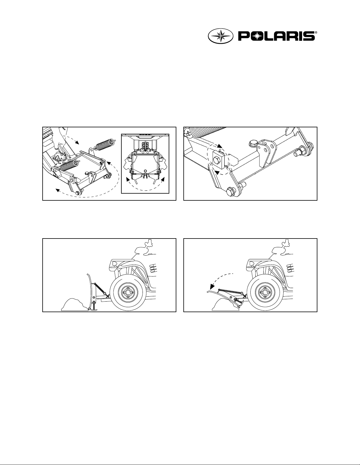
To adjust the blade angle for plowing to the side, lock Blade in the UP position. Pull the Locking Arm forward and
pivot blade to the desired position. The Locking Arm will lock into place when the blade is at the correct angle. To
tip the top of the blade forward or back, turn the four position Adjustable Blade Stops to the desired position making
the Blade more or less aggressive.
The Blade is designed to trip when it hits a solid object or digs in too far. When the pressure is released the Blade
springs back into position. Blade Spring tension may be set stiffer by tightening the Locknuts on the bottom of the
Eyebolts. For less spring tension, loosen the Locknuts.
OPERATION
Page 13

Imprimé en Chine / Printed in China
7515212
A-7515212
“GLACIER-II” PLOW FRAME
KIT PN 2878822
- 5 -
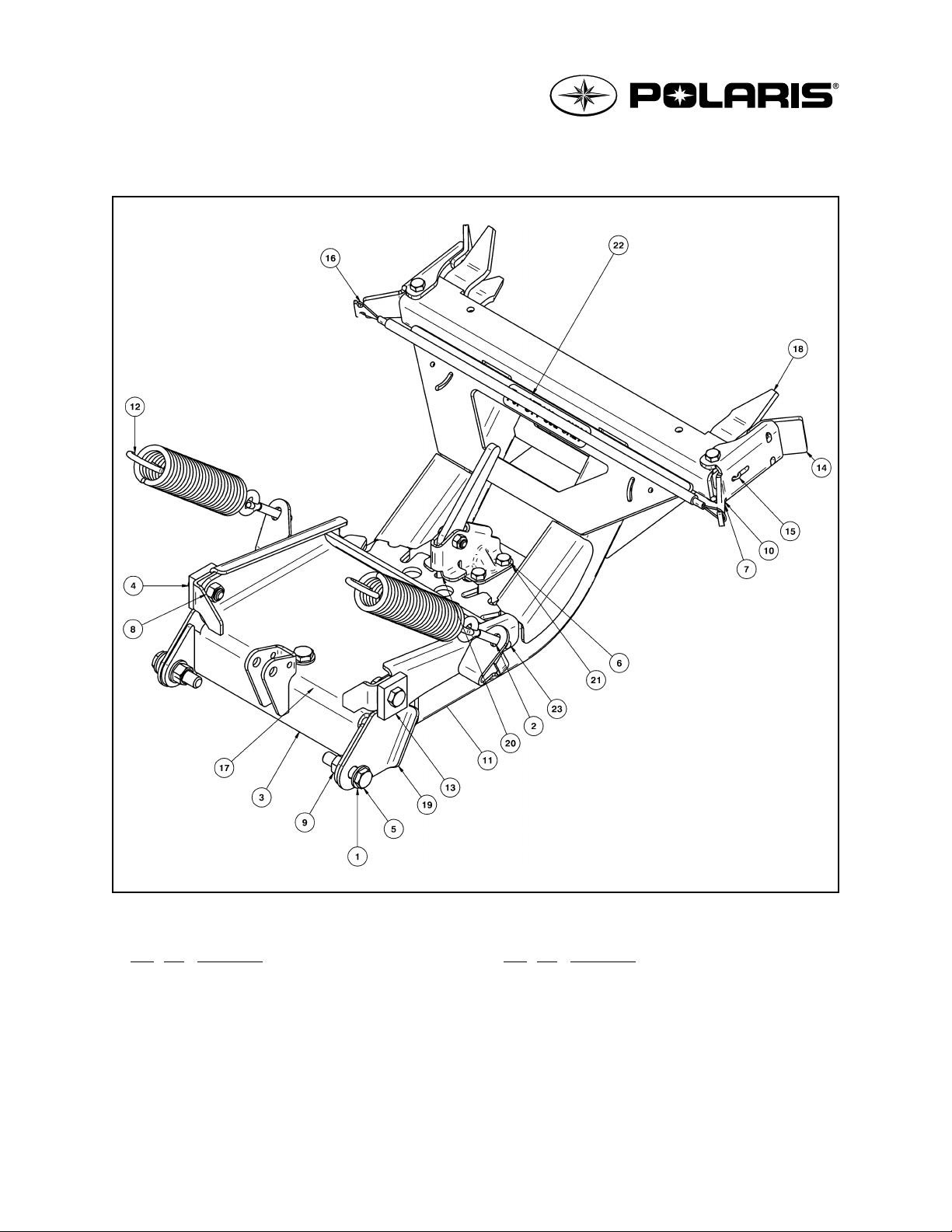
Parts List - Plow Frame
Ref. Qty Description
1 6 M12 Flat Washer
2 2 M8 Flat Washer
3 1 M12-1.75 X 90 mm Hex Bolt
4 2 M10-1.5 X 30 mm Hex Bolt
5 2 M12-1.75 X 50 mm Hex Bolt
6 5 M8-1.25 X 25 mm Hex Bolt
7 2 M8-1.25 X 65 mm Hex Bolt
8 2 M10-1.5 Nylock Nut
9 3 M12-1.75 Nylock Nut
10 9 M8-1.25 Nylock Nut
11 1 13 mm dia X 58 mm X 2.21 N/mm
Locking Arm Spring
(not shown)
Ref.
Qty Description
12 2 41 mm dia X 201 mm Tension Spring
13 2 Adjustable Blade Stop
14 2 Latch
15 2 Exhaust Spring
16 1 1/16” dia X 19.85” Cable
17 1 Pivot Sleeve (not shown)
18 1 Pushframe
19 1Pivot
20 1 Locking Arm
21 1 Locking Arm Bracket
22 1 Safety Sticker
23 2 M8-1.25 X 60 mm Eyebolt
Page 14

Imprimé en Chine / Printed in China
7515212
A-7515212
“GLACIER-II” PLOW FRAME
KIT PN 2878822
- 6 -
FRAME ASSEMBLY INSTRUCTIONS
NOTE:The parts described in steps 1 and 2 are included
in the Mount Plate Kit (PN 2877906, 2878835 or
2878824).
1. Install the M6-1.0 X 40 mm hex bolt (#B) and screw the
M6-1.0 nylock nut (#C) as illustrated.
2. Fasten the pull bar (#A) to the pivot using a M10-1.5
X 45 mm hex bolt (#D) and a M10-1.5 nylock nut (#E).
3. Fasten the snow plow to the pivot using (2)
M12-1.75 X 50 mm hex bolts (#5), (4) M12 flat washers
(#1), and (2) M12-1.75 nylock nuts (#9).
NOTE: To allow blade to trip, do not overtighten.
4. Insert the (2) 41 mm dia X 201 mm tension springs (#12)
into the snow plow upper holes and fasten the other
ends of the springs to the pivot using the (2) M8-1.25
X 60 mm eyebolts (#23), the (2) M8 flat washers (#2),
and the (2) M8-1.25 nylock nuts (#10).
Page 15

7515212
A-7515212
“GLACIER-II” PLOW FRAME
KIT PN 2878822
- 7 -
Imprimé en Chine / Printed in China
SPARE KITS
Locking Arm
Kit
P/N 2204642
Spring Blade
Kit
P/N 2877443
Cable Kit
P/N 2877452
Latch Kit
P/N 2877450
Latch Spring
Kit
P/N 7042029
Adjustable
Blade Stop Kit
P/N 2877504
Pivot Kit
P/N 2204641
Pushframe
Kit
P/N 2204640
Hardware
Kit
P/N 2878825
REF. PART DESCRIPTION
1. M12 Flat Washer 6x
2. M8 Flat Washer 2x
3. M12-1.75 X 90 mm Hex Bolt 1x
4. M10-1.5 X 30 mm Hex Bolt 2x
5. M12-1.75 X 50 mm Hex Bolt 2x
6. M8-1.25 X 25 mm Hex Bolt 5x
7. M8-1.25 X 65 mm Hex Bolt 2x
8. M10-1.5 Nylock Nut 2x
9. M12-1.75 Nylock Nut 3x
10. M8-1.25 Nylock Nut 4x 5x
11. 13 mm dia X 58 mm
Locking Arm Spring 1x
12. 41 mm dia X 201 mm
Tension Spring 2x
13. Adjustable Blade Stop 2x
14. Latch 1x
15. Exhaust Spring 2x
16. 1/16” dia X 19.85” Cable 1x
17. Pivot Sleeve 1x
18. Pushframe 1x
19. Pivot 1x
20. Locking Arm 1x
21. Locking Arm Bracket 1x
22. Safety Sticker
23. M8-1.25 X 60 mm Eyebolt 2x
 Loading...