

Polaris FST Classic, FS Classic 2006, FST Classic 2006, FS Touring 2006, FST Touring 2006 Owner's Manual
...Page 1
Page 2
Page 3
WARNING
WARNING
Read, understand, and follow all of the instructions
and safety precautions in this manual and on all
product labels.
Failure to follow the safety precautions could result
in serious injury or death.
The engine exhaust from this product
contains chemicals known to the State
of California to cause cancer, birth
defects or other reproductive harm.
PROPOSITION 65
WARNING
Snowmobile engines discharge fuel
and exhaust, which contain chemicals
known to the State of California to
cause cancer and birth defects or other
reproductive harm, onto the snow on
which they operate. Keep this engine
properly tuned and avoid unnecessary
idling and spillage during fueling.
Page 4

1
WELCOME
Thank you for purchasing a Polaris vehicle, and welcome to our
world-wide family of Polaris owners. We proudly produce an exciting
line of utility and recreational products.
S Snowmobiles
S All-terrain vehicles (ATVs)
S RANGER utility vehicles
S Victory motorcycles
We believe Polaris sets a standard of excellence for all utility and
recreational vehicles manufactured in the world today. Many years of
experience have gone into the engineering, design, and development of
your Polaris vehicle, making it the finest machine we’ve ever
produced.
For safe and enjoyable operation of your vehicle, be sure to follow the
instructions and recommendations in this owner’s manual. Your
manual contains instructions for minor maintenance, but information
about major repairs is outlined in the Polaris Service Manual and
should be performed only by a Factory Certified Master Service Dealer
(MSD) Technician.
Your Polaris dealer knows your vehicle best and is interested in your
total satisfaction. Be sure to return to your dealership for all of your
service needs during, and after, the warranty period.
We also take great pride in our complete line of apparel, parts and
accessories, available through our online store at
www.purepolaris.com. Have your accessories and clothing delivered
right to your door!
Page 5

2
POLARIS and POLARIS THE WAY OUT are registered trademarks of Polaris
Industries Inc.
RIDER SELECT is a trademark of Polaris Industries Inc.
Copyright 2005 Polaris Sales Inc. All information contained within this publication is
based on the latest product information at the time of publication. Due to constant
improvements in the design and quality of production components, some minor
discrepancies may result between the actual vehicle and the information presented in this
publication. Depictions and/or procedures in this publication are intended for reference
use only. No liability can be accepted for omissions or inaccuracies. Any reprinting or
reuse of the depictions and/or procedures contained within, whether whole or in part, is
expressly prohibited.
Printed in U.S.A.
2006 FS/FST Classic/Touring & FST Switchback Owner’s Manual P/N 9919670
Page 6

3
TABLE OF CONTENTS
Introduction 5...............................
This section contains helpful information for owners and drivers and
illustrates t he location of important identification numbers that should
be recorded in the owner’s manual.
Safety 8.....................................
This section describes safe vehicle operation and identifies warning
decals and their locations.
Features 27..................................
This section identifies the locations of your snowmobile’s controls and
features.
The Perfect Fit 46............................
This section explains how to tailor the suspension and other features
for an optimum riding experience.
Pre-Ride Inspections 64......................
This section explains procedures that must be performed before riding.
Operation 73.................................
This section explains proper engine break-in, operation of features and
general operating procedures.
Maintenance 85..............................
This section defines your role, and your dealer’s role, in your
snowmobile’s regular maintenance.
Polaris Products 133.........................
Troubleshooting 134.........................
Warranty 141................................
Maintenance Log 149.........................
Index 152....................................
Page 7

4
Page 8

5
INTRODUCTION
Important Notes for Owners and Drivers
After reading this manual, store it in the snowmobile for convenient
reference. It should remain with the snowmobile when the snowmobile
is sold.
Some of the illustrations and photos used in this manual are general
representations. Your model may differ.
Follow the maintenance program outlined in this manual. Preventive
maintenance ensures that critical components of the snowmobile are
inspected by your dealer at specific mileage intervals.
You and your dealer must complete the registration form included with
your snowmobile and forward it to us. This completed form is
necessary to ensure warranty coverage.
Protect and preserve your right to ride by joining your local trail riding
clubs.
Page 9

6
INTRODUCTION
Preservation of the Environment
Polaris is committed to supporting an environmental education
campaign. We encourage state and provincial governments across the
snowbelt to adopt rigorous safety training programs that encourage
protection of our environment, including wildlife and vegetation.
Snowmobile clubs and other organizations are working together to
protect our environment. Please support their efforts and operate your
snowmobile with consideration for the protection and preservation of
our environment.
Noise Level
One of the most publicized issues about snowmobiles is noise. The
Society of Automotive Engineers (SAE), the standard-setting body for
snowmobile development, recommends that snowmobiles conform to
prescribed sound levels.
Polaris snowmobiles are engineered to conform to these SAE
standards. Our muffler systems are designed to reduce noise levels and
must not be altered or removed. The sound of your snowmobile may
not be welcome to non-snowmobilers, so you have a responsibility to
operate your snowmobile with concern for others. We do our part by
manufacturing quieter machines; we ask your help to further reduce the
impact of noise by operating your snowmobile safely and responsibly.
Page 10
7
INTRODUCTION
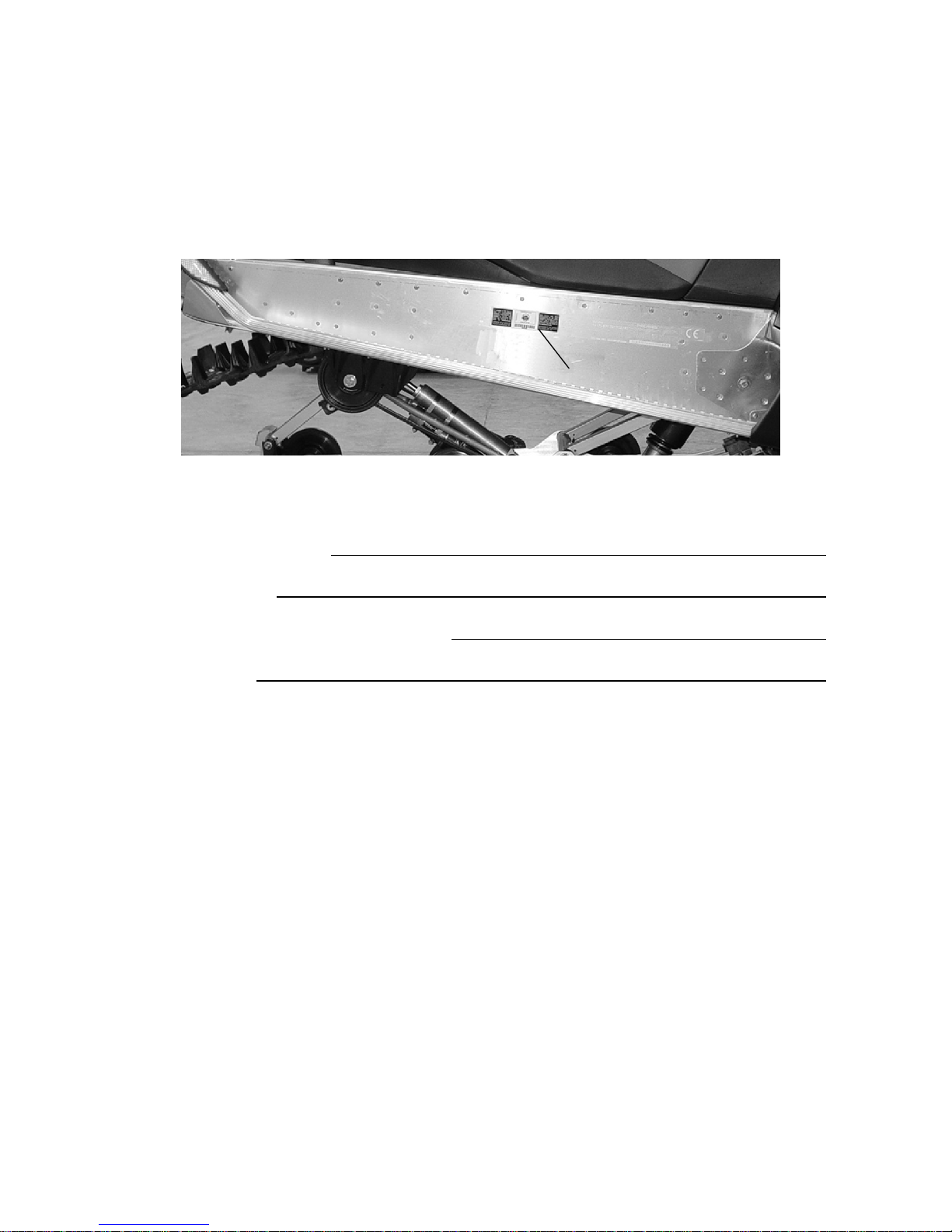
Vehicle Identification Numbers
Record your snowmobile’s identification numbers and key number in
the spaces provided. Remove the spare key and store it in a safe place.
Your key can be duplicated only by mating a Polaris key blank with
one of your existing keys, so if both keys are lost, the ignition switch
must be replaced.
Vehicle Model Number:
Tunnel VIN (L):
Engine Serial Number (on valve cover):
Key Number:
L
Page 11

8
SAFETY
Operator Safety
The following signal words and symbols appear throughout this
manual and on your vehicle. Your safety is involved when these words
and symbols are used. Become familiar with their meanings before
reading the manual.
The safety alert symbol, on your vehicle or in this manual, alerts
you to the potential for injury.
WARNING
The safety alert warning indicates a potential hazard that may
result in serious injury or death.
CAUTION
The safety alert caution indicates a potential hazard that may
result in minor injury or damage to the vehicle.
CAUTION
A caution indicates a situation that may result in damage to the
vehicle.
NOTE:
A note will alert you to important information or instructions.
Page 12

9
SAFETY
Operator Safety
Follow the recommended maintenance program outlined beginning on
page 87 of this manual to ensure that all critical components on the
snowmobile are thoroughly inspected by your dealer at specific
mileage intervals.
WARNING
Driving a snowmobile requires your full attention. DO NOT drink
alcohol or use drugs or medications before or while driving or
riding as a passenger. They will reduce your alertness and slow
your reaction time.
Snowmobiles are capable of traveling at high speeds. Use extra
caution to ensure operator safety. Make sure your snowmobile is
in excellent operating condition at all times. Always check major
and vital safety components before every ride.
All Polaris snowmobiles are designed and tested to provide safe
operation when used as directed. Failure of critical machine
components may result from operation with any modifications,
especially those that increase speed or power. DO NOT
MODIFY YOUR MACHINE. The snowmobile may become
aerodynamically unstable at speeds higher than those for which it
is designed. Loss of control may occur at higher speeds.
Modifications may also create a safety hazard and lead to bodily
injury .
The warranty on your entire machine is terminated if any
equipment has been added, or any modifications have been
made, to increase the speed or power of the snowmobile.
Page 13
10
SAFETY
Operator Safety
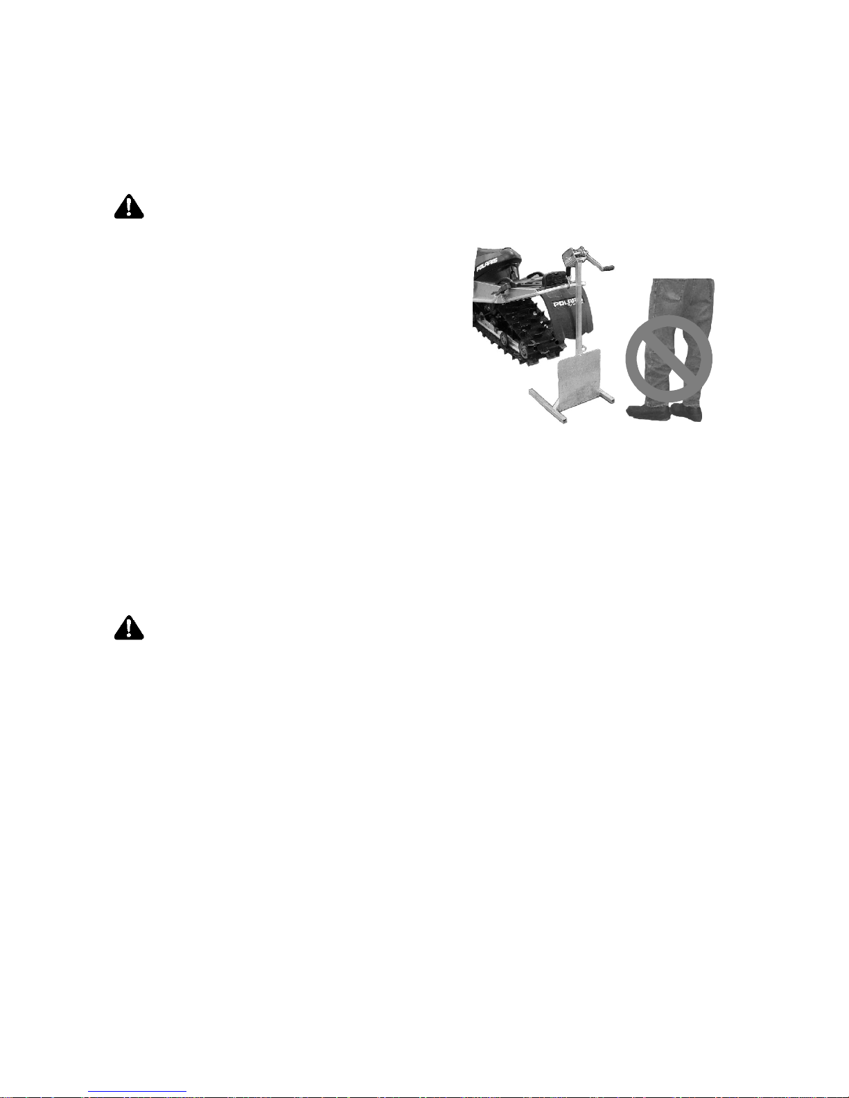
Stay Clear of Track
Your snowmobile is propelled by a revolving track that must be
partially exposed for proper operation.
WARNING
Serious injuries may result if
hands, feet, or clothing become
entangled in the track. Be alert
when riding, and remain properly
seated to stay clear of the track.
Never hold the snowmobile up or
stand behind it while warming up
the track. A loose track or flying
debris could cause serious injury or
death. We recommend having your
dealer perform all track service and
alignment procedures.
Stay Clear of Engine
Never attempt adjustments with the engine running. Turn off the
ignition, raise the hood, make the adjustment, secure shields and
guards, secure the hood, and then restart the engine to check its
operation.
WARNING
Serious injury can occur if fingers or clothing contact the moving
parts of an engine. Always stop the engine before attempting
adjustments.
Page 14

11
SAFETY
Operator Safety
Riding Position
Operating a snowmobile requires skill and balance for proper control.
Rider positions may vary with experience; but under many conditions,
the proper position is to be seated with both feet on the running boards
and both hands on the handlebar grips for proper throttle, brake and
steering control.
WARNING
Improper riding position may reduce control and could result in
serious injury or death. Always ride in a position that allows for
control of your vehicle.
Survival Preparation
For your safety, always ride in a group of other snowmobilers. Always
tell someone where you’re going and how long you expect to be gone.
If it isn’t possible to ride with others, and you must travel into remote
areas, always carry survival equipment that’s appropriate to the
conditions you may encounter. Such equipment may include, but is
not limited to: extra clothing, a sleeping bag, a flashlight, food and
water, a signaling mirror, a means of building a fire, and a two-way
radio or cellular telephone.
For added protection, carry the following items on your snowmobile at
all times:
SSpare Drive Belt SExtra Set of Spark Plugs
STow Rope SExtra Oil
SFuel Deicer SW inter Survival Kit
STrail Map SOwner’s Manual
SFirst Aid Kit STool Kit
Page 15
12
SAFETY
Operator Safety
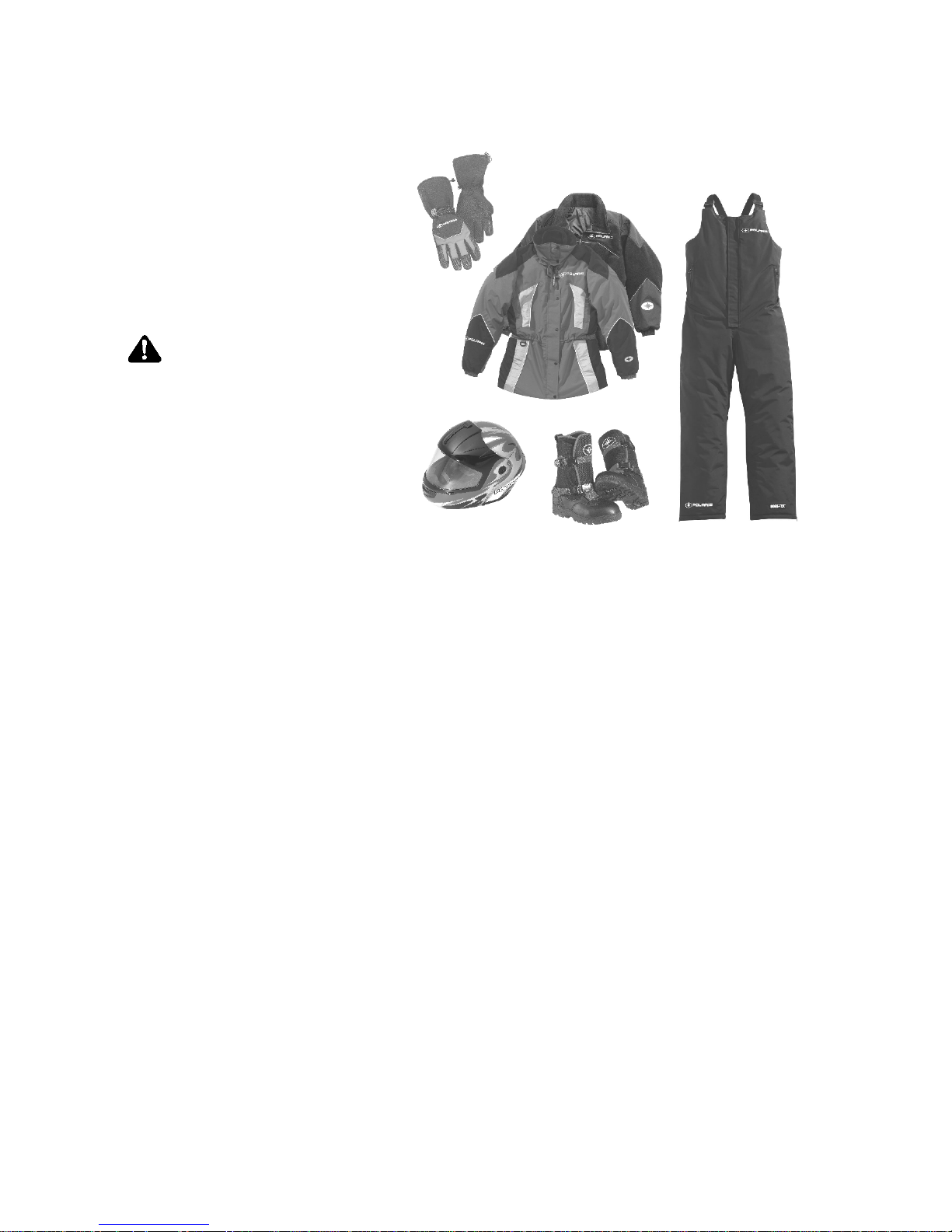
Riding Apparel
Be prepared, be warm and be
comfortable when riding. B e
aware of the weather
forecast, especially the
windchill, and dress
accordingly. See the chart
on page 22.
WARNING
Avoid wearing loose
clothing or long
scarves, which can
become entangled in
moving parts and
cause serious injury.
Always wear an
approved helmet and
eye protection.
Disabled Operators
Safe operation of this rider-active vehicle requires good judgement and
physical skills. Operators with cognitive or physical disabilities have
an increased risk of loss of control, which could result in serious injury
or death.
Cargo Overload (Touring)
Too much weight on the rear of the machine may reduce your ability to
steer. Do not exceed carrier and rack weight limits, and do not allow a
passenger to sit on the seat back or the cargo carrier.
Page 16

13
SAFETY
Operator Safety
Rider Capacity
Driving 1-Up - Some Polaris snowmobiles are designed for a single
rider only. A decal on the console of these models indicates single
rider operation.
Driving 2-Up - Some Polaris snowmobiles are designed for up to two
riders. A decal on the hood of these models indicates that the vehicle
is designed for one operator and one passenger only.
WARNING
Control becomes more difficult with two people on board. More
space is required to make turns, and longer distances are needed
for stopping. Make sure the passenger remains seated behind
the driver, facing forward, with both feet placed firmly on the
running boards. Slow down and avoid “jumping” your
snowmobile.
Snowmobiles designed for two riders should never be operated with
more than two people on board. When traveling with a passenger, it’s
the driver’s responsibility to operate the snowmobile safely.
Slow down! Control becomes more difficult with two people on board.
More space is required to make turns, and longer distances are
necessary for stopping.
Page 17

14
SAFETY
Operator Safety
Excessive Speed
WARNING
High speed driving, especially at night, could result in serious
injury or death. Always reduce speed when driving at night or in
inclement weather.
Always observe all state and local laws governing snowmobile
operation and speed limits. Always be alert and pay attention to the
trail ahead. Multiplying speed (MPH) by 1.5 will equal the
approximate number of feet per second your snowmobile travels. If
your speed is 40 MPH, your snowmobile is traveling about 60 feet per
second. If you look back for only t wo seconds, your snowmobile will
travel about 120 feet. If your speed is 60 MPH, your snowmobile will
travel about 180 feet in two seconds.
Traveling at night requires extra caution. Check headlight and taillight
to ensure proper operation, and don’t over-drive your headlight beam.
Always be able to bring your snowmobile to a stop in the distance
illuminated by the headlight.
Page 18
15
SAFETY
Operator Safety
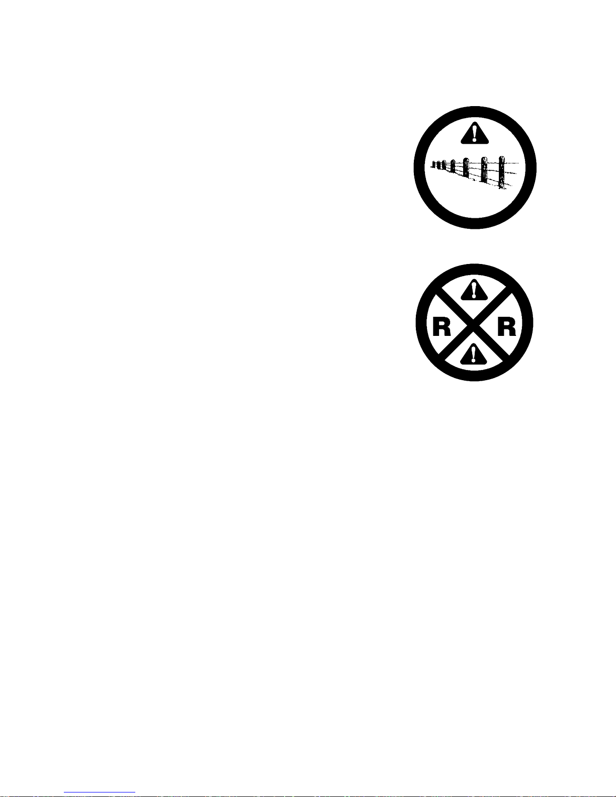
Driver Awareness
Slow down when traveling near poles,
posts, or other obstacles. Be especially
alert if you’re snowmobiling after dark.
Always be on the alert for wire fences.
Single strands are especially dangerous,
since there may be a great distance
between posts. Guy wires on utility poles
are also difficult to distinguish.
Make sure the way is clear before crossing
railroads and other roads and highways.
The noise of your snowmobile will drown
out the sound of approaching vehicles.
Look ahead, behind, and to both sides
before turning or crossing railroad tracks
or highways. Steep embankments may
also hide your view. Always leave
yourself a way out.
Variances in snow depth and/or water
currents may result in uneven ice
thickness. You may drown if you break
through the ice. Avoid travelling on frozen bodies of water.
When teaching inexperienced operators to ride, set up a predetermined
course for practice. Make sure they know how to drive and control the
snowmobile before allowing them to make longer trips. Teach them
proper snowmobile courtesy, and enroll them in driver’s training and
safety courses sponsored by local or state organizations.
Page 19

16
SAFETY
Operator Safety
Avalanches
Snowmobilers should always be properly
trained and equipped before traveling in
mountainous terrain:
S Take an avalanche class
S Travel with experienced people
S Travel on designated trails
S Make sure each person is equipped with
a shovel, probe and avalanche beacon.
You don’t have to be snowmobiling on a slope for an avalanche to
occur. Be aware that all of the snow is connected. You may be riding
on a flat slope or snow covered road, but if the snowpack above is
unstable enough you can trigger an avalanche on a steeper slope above
you. Always be aware of snow conditions above you as you travel in
mountainous terrain.
Before riding in mountainous terrain, call or log on to your local
avalanche advisory to get current weather and snow stability
information.
For more information about avalanche training and avalanche
conditions, contact local law enforcement in your area, or visit either
the American Avalanche Association online at
www.americanavalancheassociation.org or the U.S. Forest Service
National Avalanche Center at www.avalanche.org.
Page 20

17
SAFETY
Operator Safety
Ice and Snow Build-up
WARNING
Ice and snow build-up may interfere with the steering of your
snowmobile, resulting in serious injury or death. Keep the
underhood area free of snow and ice.
Before driving, manually turn the skis to the left and right to be sure
ice and snow are not interfering with full left and right steering. If
difficulty is encountered, remove ice and snow build-up that may be
obstructing the steering linkage.
NOTE: If your snowmobile is equipped with RIDER SELECT,
perform this check in both the full up and full down steering
positions.
Driving Downhill
When riding downhill, shift your weight to the rear of the snowmobile
and reduce your speed to a minimum. Apply just enough throttle to
keep the clutch engaged, allowing the engine’s compression to help
slow the snowmobile and keep it from rolling freely downhill.
WARNING
When driving on long downhill stretches, pump the brakes.
Riding the brakes may cause the brake system to overheat,
which may result in brake failure.
Excessive or repetitive use of the brakes for high speed stops will
also cause an overheated brake system. This condition may lead
to a sudden loss of brakes and/or fire and may result in serious
injury or death.
Page 21

18
SAFETY
Operator Safety
Driving on Slippery Surfaces
WARNING
Never attempt an abrupt change of direction when operating on
slippery surfaces. Proceed slowly and use extra caution.
Driving on ice or hard-packed snow reduces steering and braking
control, which may result in loss of control and serious injury or
death. Slow down and use extra caution when operating on
slippery surfaces.
Driving in Hilly Terrain
WARNING
Climbing a hill or crossing the face of a slope may result in loss of
balance and snowmobile rollover, causing serious injury or death.
Use caution and good judgement when driving in hilly terrain.
Use extra caution when operating i n hilly terrain. If climbing a hill is
unavoidable, keep your weight low and forward. If you must cross the
face of a slope, keep your weight on the uphill side of the snowmobile
to maintain proper balance and avoid possible rollover.
Slow down when reaching the crest of a hill. Be prepared to react to
obstacles, sharp drops or other people or vehicles that m ay be on the
other side of the hill.
If you’re unable to continue up a hill, turn the snowmobile downhill
before it loses momentum. If this isn’t possible, spin the track just
enough to dig in to prevent it from rolling back down the hill. St op the
engine and set the parking brake (if equipped). Keeping away from the
downhill side of the snowmobile, pull the rear of the snowmobile
around and point the front end and skis downhill. Remount the
snowmobile, restart the engine, release the parking brake, and descend
the hill carefully.
Page 22

19
SAFETY
Operator Safety
Drive Belt
Do not operate the engine with the drive belt removed.
Any servicing that requires operation without a belt must be performed
by your dealer. Operation of the engine with the belt removed may
result in injury or damage to the engine.
Intake Silencer
Do not operate the engine with the intake silencer or filter removed.
Damage to the engine may occur if the intake silencer or filter are
removed.
Clutches
Do not attempt to service the clutches.
All clutch service must be performed by your dealer. The clutch is a
complex mechanism that rotates at high speeds. Each clutch is
dynamically balanced before installation. Any tampering may disrupt
this precision balancing and create an unstable condition.
Cold Weather Drive-Away
Whenever your snowmobile has been parked for a length of time,
especially overnight, always make sure the skis and track are loosened
from ice and snow before attempting to drive. Apply the throttle with
enough authority to put the snowmobile into motion, but always
operate within safety limits and, on 2-Up machines, with respect for a
passenger.
Maneuverability
While much control and maneuverability is achieved through the
steering system and skis, maximum control is achieved by the shifting
of your body weight. Maneuverability will change for lighter operators
or snowmobiles designed to carry a load or a passenger.
Page 23

20
SAFETY
Operator Safety
Inadequate Snow Conditions
Since snow provides the only lubrication for the power slide
suspension and, on liquid cooled models, cooling for the engine,
adequate snow cover is a requirement for operation of your
snowmobile. Driving in too little snow will result in excessive wear
and damage to the slide rail, track and/or engine.
WARNING
Inadequate cooling and lubrication will lead to overheating of the
slide rail and track, causing premature wear, damage and failure,
which can result in serious injury. Reduce speeds and frequently
drive into fresh snow to allow adequate cooling and polishing of
the slide rail and track surfaces. Avoid operating for prolonged
periods on ice, hard-packed surfaces or roads.
Operating in Deep Snow
If the snowmobile becomes stuck in snow, clear the running board area
of snow, then step down t he snow in front of the snowmobile so that
when the throttle is opened, the snowmobile will be able to climb up
and over the snow.
Page 24

21
SAFETY
Operator Safety
Driving Responsibly
Every snowmobile handles differently, and even the most docile
conditions may become dangerous if operators drive improperly. If
you’re new to snowmobiling, acquaint yourself with the snowmobile
and with what it will and won’t do under various conditions. Even
seasoned drivers should spend some time getting the feel for a
snowmobile before attempting ambitious maneuvers.
S A snowmobile depends on the rider’s body position for proper bal-
ance in executing turns, t raversing hills, etc. Always start on a
smooth, level area to begin building your operating experience.
S Before allowing someone else use your snowmobile, know the ex-
tent of their operating skills. Check to see if they’ve taken a snowmobile safety course and have an operator’s certificate. For their
protection, as well as yours, make sure they take a snowmobile safety course. Everyone can benefit from the course.
S Don’t “jump” your snowmobile. Jumping may injure your back be-
cause of spinal compression. The seat and suspension of your snowmobile have been designed to provide protection under normal
riding conditions. Your snowmobile is not intended for this kind of
use.
S Be courteous to oncoming traffic by dimming your headlights and
reducing your speed.
S When traveling in a group of snowmobiles, don’t tailgate (follow too
closely). Leave enough distance between snowmobiles to provide
ample stopping room and to provide protection from flying snow
and debris. Allow even more distance when driving on slippery surfaces or when driving in darkness or other low visibility conditions.
Be aware of any snowmobile traffic around your vehicle. Drive defensively to avoid accidents.
S Remove the key from the ignition when you leave the snowmobile
unattended.
Page 25
22
SAFETY
Operator Safety
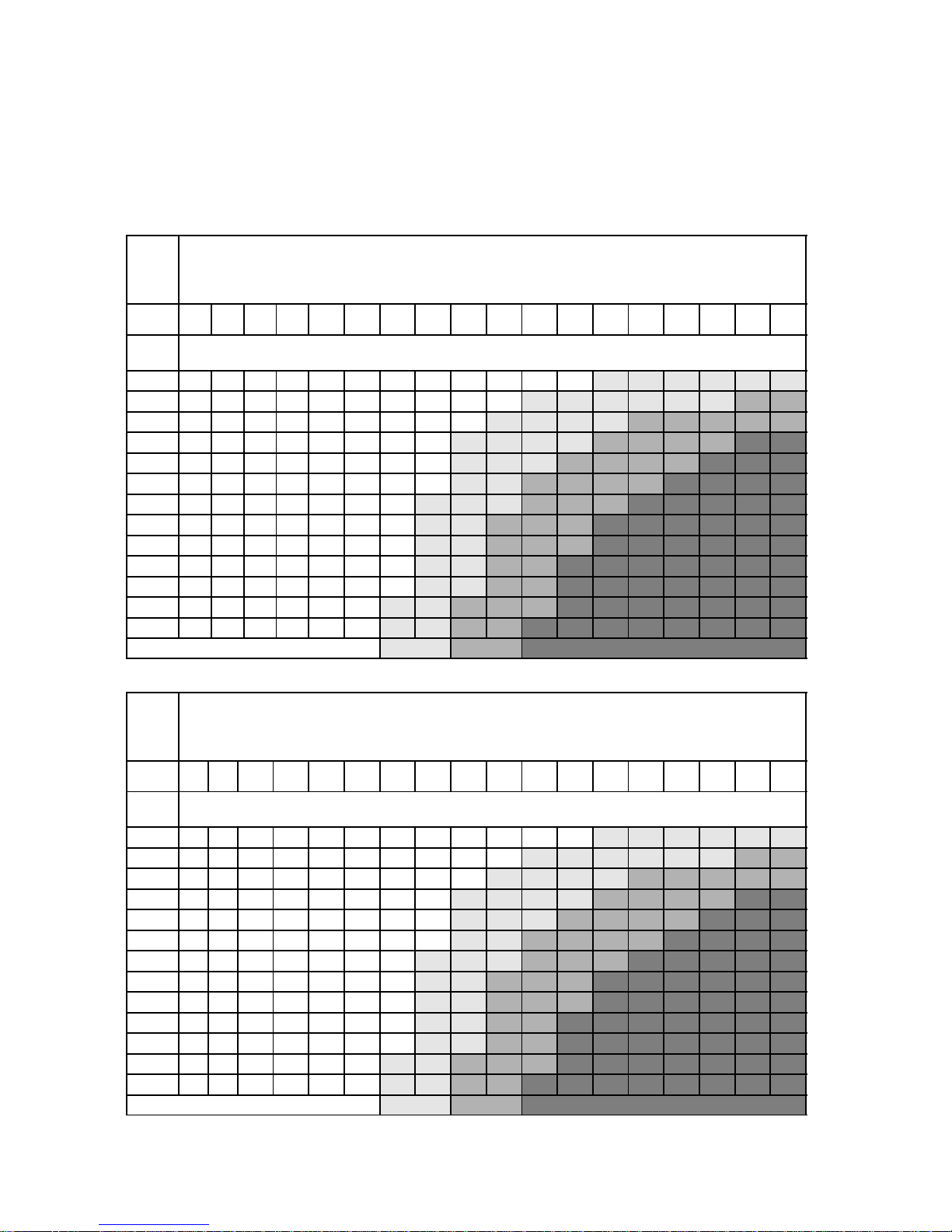
Windchill/Temperature Charts
The following information is provided to help you determine when
temperatures become dangerous for riding.
WIND CHILL CHART (°F)
Wind
Speed
in
MPH
Actual Thermometer Reading (°F)
40 35 30 25 20 15 10 5 0 -5 -10 -15 -20 -25 -30 -35 -40 -45
Equivalent Temperature (°F)
Calm 40 35 30 25 20 15 10 5 0 -5 -10 -15 -20 -25 -30 -35 -40 -45
5 36 31 25 19 13 7 1 -5 -11 -16 -22 -28 -34 -40 -46 -52 -57 -63
10 34 27 21 15 9 3 -4 -10 -16 -22 -28 -35 -41 -47 -53 -59 -66 -72
15 32 25 19 13 6 0 -7 -13 -19 -26 -32 -39 -45 -51 -58 -64 -71 -77
20 30 24 17 11 4 -2 -9 -15 -22 -29 -35 -42 -48 -55 -61 -68 -74 -81
25 29 23 16 9 3 -4 -11 -17 -24 -31 -37 -44 -51 -58 -64 -71 -78 -84
30 28 22 15 8 1 -5 -12 -19 -26 -33 -39 -46 -53 -60 -67 -73 -80 -87
35 28 21 14 7 0 -7 -14 -21 -27 -34 -41 -48 -55 -62 -69 -76 -82 -89
40 27 20 13 6 -1 -8 -15 -22 -29 -36 -43 -50 -57 -64 -71 -78 -84 -91
45 26 19 12 5 -2 -9 -16 -23 -30 -37 -44 -51 -58 -65 -72 -79 -86 -93
50 26 19 12 4 -3 -10 -17 -24 -31 -38 -45 -52 -60 -67 -74 -81 -88 -95
55 25 18 11 4 -3 -11 -18 -25 -32 -39 -46 -54 -61 -68 -75 -82 -89 -97
60 25 17 10 3 -4 -11 -19 -26 -33 -40 -48 -55 -62 -69 -76 -84 -91 -98
Frostbitein>> 30 min. 10 min. 5min.
WIND CHILL CHART (°C)
Wind
Speed
in
KPH
Actual Thermometer Reading (°C)
5 2 -1 -4 -7 -10 -13 -16 -19 -22 -25 -28 -31 -34 -37 -40 -43 -46
Equivalent Temperature (°C)
Calm 5 2 -1 -4 -7 -10 -13 -16 -19 -22 -25 -28 -31 -34 -37 -40 -43 -46
8 3 0 - -7 -11 -14 -18 -22 -25 -29 -32 -36 -39 -43 -46 -50 -53 -57
16 2 -2 -6 -10 -13 -17 -21 -24 -28 -32 -36 -39 -43 -47 -50 -54 -58 -62
24 1 -3 -7 -11 -15 -19 -22 -26 -30 -34 -38 -42 -45 -49 -53 -57 -61 -65
32 0 -4 -8 -12 -16 -20 -24 -28 -32 -36 -39 -43 -47 -51 -55 -59 -63 -67
40 -1 -5 -9 -13 -17 -21 -25 -29 -33 -37 -41 -45 -49 -53 -57 -61 -65 -69
48 -1 -5 -9 -13 -18 -22 -26 -30 -34 -38 -42 -46 -50 -54 -58 -62 -66 -70
56 -2 -6 -10 -14 -18 -22 -26 -31 -35 -39 -43 -47 -51 -55 -59 -64 -68 -72
64 -2 -6 -10 -15 -19 -23 -27 -31 -35 -40 -44 -48 -52 -56 -61 -65 -69 -73
72 -2 -7 -11 -15 -19 -23 -28 -32 -36 -40 -45 -49 -53 -57 -61 -66 -70 -74
80 -3 -7 -11 -15 -20 -24 -28 -33 -37 -41 -45 -50 -54 -58 -62 -67 -71 -75
88 -3 -7 -12 -16 -20 -24 -29 -33 -37 -42 -46 -50 -55 -59 -63 -67 -72 -76
96 -3 -8 -12 -16 -21 -25 -29 -34 -38 -42 -47 -51 -55 -60 -64 -68 -73 -77
Frostbitein>> 30 min. 10 min. 5min.
Page 26
23
SAFETY
Safety Decals and Locations
Warning decals have been placed on the snowmobile for your
protection. Read and follow the instructions of the decals and other
warnings on the snowmobile carefully. If any of the decals depicted in
this manual differ from the decals on your snowmobile, always read
and follow the instructions of the decals on the snowmobile.
If any decal becomes illegible or comes off, contact your Polaris dealer
to purchase a replacement. Replacement safety decals are provided by
Polaris at no charge. The part number is printed on the decal.
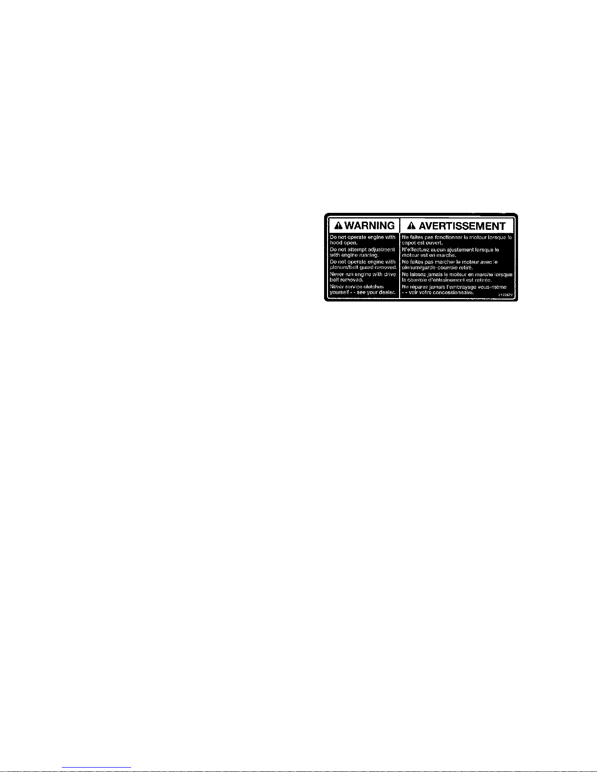
Clutch Cover Warning
This warning decal is found
under the hood on the clutch
cover:
Warming
Do not operate with hood open.
Do not attempt adjustment with engine running.
Do not operate engine with plenum/belt guard
removed.
Never run engine with drive belt removed.
Never service clutches yourself. See your dealer.
Pressure Cap Warning
This warning decal is found under the hood on the pressure cap of
applicable liquid cooled models:
Warming
Do not open hot. Test or replace when changing
coolant. Press down and turn to release cap. 13
PSI
Page 27
+
24
SAFETY
Safety Decals and Locations
“No Passenger” Warning
Snowmobiles designed for a
single rider only have a
warning decal on the console
below the steering post:
Warming
This vehicle is designed for
operator only.
“NO PASSENGER”
Passenger Warning
Snowmobiles designed for an operator and one passenger have a
warning decal at the right side of the steering post. For more
information on operating with a passenger, see page 13.
Warming
This vehicle is designed for
operator and “ONE” passenger only.
Track Warning
Warming
Stay clear of track. Do not sit on
seat back. Entanglement with the
track or a fall from seat back may
result in severe injury or death.
+
Page 28

25
SAFETY
Safety Decals and Locations
Reverse Warning
Reverse operation, even at low speeds, may cause loss of control
resulting in serious injury or death. To avoid loss of control,
always:
S Look behind before and while backing.
S Avoid sharp turns.
S Shift to or from reverse only when stopped.
S Apply throttle slowly.
NOTE: For more information, see Owner’s Manual.
If electric reverse:
S Machine stopped and engine at idle, push yellow button on LH
controlto reverse.Flashing lighton dash indicates reverseoperation.
S Push button again to return to forward.
+
+
Page 29

26
SAFETY
Safety Decals and Locations
Operation Warning
S To avoid serious injury or death,
read and understand all warnings
and the Owner’s Manual before
operation. If the manual is miss-
ing, contact a Polaris dealer for a
replacement.
S This vehicle is capable of high
speeds. Buried objects or un-
even terrain can cause loss of
control. Reduce speed and use
extreme caution when operating
in unfamiliar terrain.
S Excessive speed, especially at
night or with limited visibility, can
result in insufficient time for you
to react to terrain changes, to avoid unexpected obstacles, or to stop safely.
S Never consume alcohol or drugs before or while operating this vehicle.
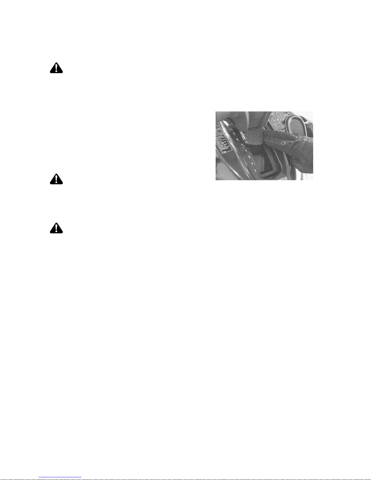
S In an emergency, push down the Auxiliary Shut-Off Switch, located on the top
of the throttle control assembly, to stop the engine. Then pull the brake lever
to stop.
S Always wear an approved helmet, eye protection, and adequate clothing
while operating this vehicle.
S This vehicle is designed for adult use only. Check local laws for age require-
ments.
S When operating with a passenger (on approved models only) reduce speed
and allow extra space for steering and stopping. A passenger reduces your
ability to control the vehicle.
S When operating on hard-packed snow, ice, or when crossing roads, steering
and braking ability are greatly reduced. Reduce speed and allow extra space
to turn or stop.
S To maintain vehicle control on ice or hard-packed surfaces, you should have
a proper balance of ski carbides to track studs. See Owner’s Manual for
proper use of traction products.
S Repeated stops from high speed may cause fading or sudden loss of braking
ability.
S Parking brake may relax when used for long periods. Do not leave brake
engaged for more than five minutes.
S Before starting engine, check throttle, brake, and steering for proper opera-
tion. Make sure hood is latched. Be seated and in position to control the ve-
hicle.
Oil injection system: Use unmixed fuel only. Check oil level when refueling.
+
+
Page 30
27
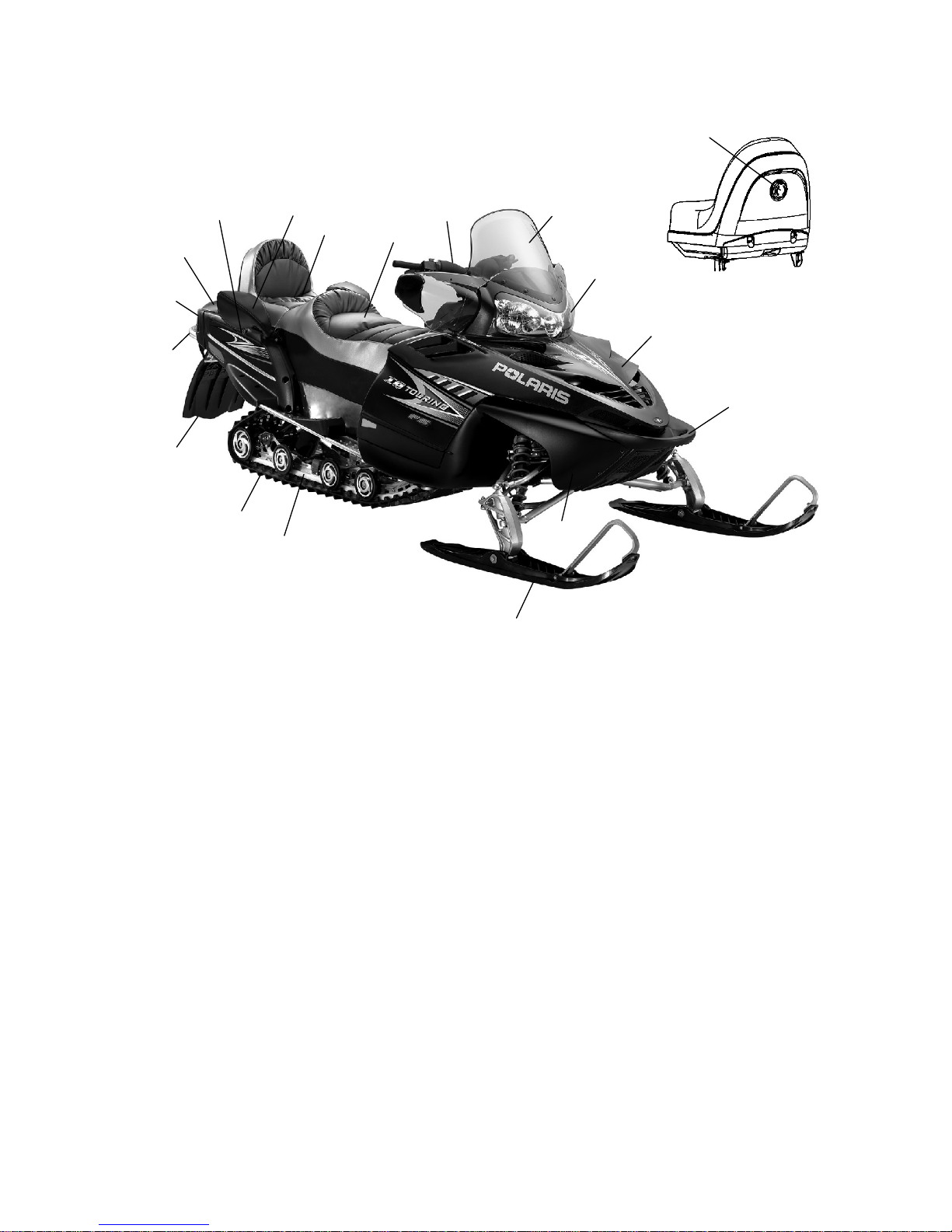
FEATURES
1. Front Bumper
2. Hood
3. Headlight
4. Passenger Lumbar Adjuster
(Touring)
5. Windshield
6. Handlebar
7. Operator Seat
8. Passenger Seat (Touring)
9. Passenger Grab Handle
10. Grab Handle Heater Switch
(Touring)
11. Trunk Cover or Storage
Compartment
12. Taillights
13. Rear Bumper
14. Snow Flap
15. Track
16. Suspension
17. Skis
18. Nosepan
14
6
5
3
2
1
7
12
15
16
18
17
13
11
9
8
4
10
Page 31
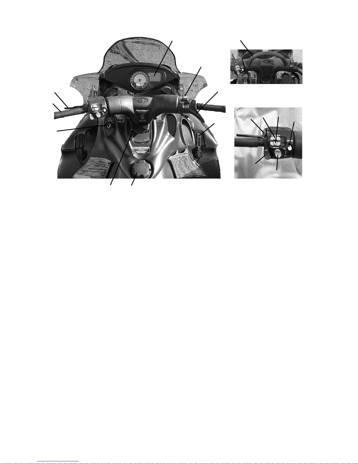
28
FEATURES
1. Fuel Filler Cap
2. Rider Selectt
3. Ignition Switch
4. Handlebar hook
5. Brake Lever
6. MFD (Multi-Function Display)
7. Engine Stop Switch
8. Throttle Control
9. Hood Hold Down Straps
10. Parking Brake
11. Handlebar Grip Warmer
Switch
12. Thumbwarmer Switch
13. Electronic Reverse Button
14. MFD Control
15. Headlight Dimmer Switch
16. Mountain Bar (if equipped)
1
7
8
3
5
6
9
4
16
2
15
10
11 12
13
14
Page 32

+
29
FEATURES
Passenger Seat (T ouring)
The passenger seat features an adjustable lumbar
support. To adjust for rider comfort, rotate the
lumbar adjustment knob (A).
Storage Compartments
Trunk (Touring)
Open the trunk cover (B) to access the rear storage compartment. The
passenger seat and trunk cover are removeable to provide open storage
for transporting larger items.
1. Remove the
trunk cover.
2. Push down on the seat
latch lever (C), which
is located at the lower
rear of the passenger
seat.
3. Lift up the seat and
remove it from the chassis.
4. Reverse the procedure to reinstall the seat and trunk cover.
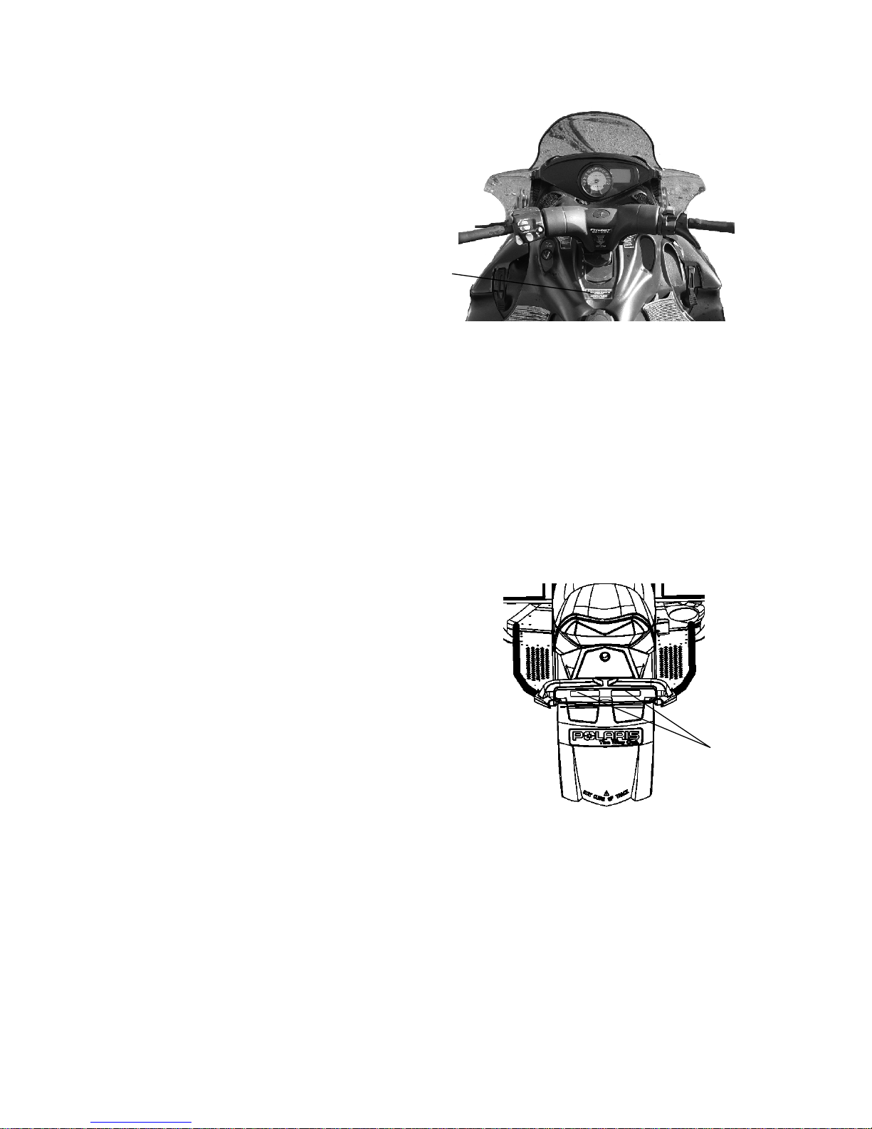
Under-Seat Storage (Switchback)
Lift the seat lever (+) and lift the
seat to access the under-seat storage
area.
Storage Compartment (Classic)
Open or close the storage
compartments with the key.
A
B
C
Page 33

+
+
30
FEATURES
Radiator Compartment
Access Panel
The access panel (+) is provided
for cleaning debris from the
radiator.
Cargo Rack (Switchback)
The maximum weight capacity
for the cargo rack (+) is 15 lbs.
(7 kg). Always secure cargo
before operating. Do not exceed
the rack weight limit. Do not
allow a passenger to sit on the
seat back or the cargo rack.
Adjustable Headlights
Adjust the headlight beam by
moving the adjuster to the left
or right.
Page 34

31
FEATURES
RIDER SELECT Adjustable Steering System
The RIDER SELECT adjustable steering system allows you to adjust
the handlebar position t o fit your style of riding. Some models have
five (5) adjustment positions. Other models have seven (7) positions.
WARNING
If your snowmobile has five adjustment positions, do not remove
the RIDER SELECT lockout. Your Polaris snowmobile has been
engineered for this range of adjustability. Removing this lockout
and using RIDER SELECT position 6 or 7 will result in the
handlebars and brake lever contacting other components and
interfering with steering and braking. This could lead to loss of
control resulting in serious injury or death. Always be sure that
the handlebars and brake lever do not contact any other
snowmobile components at any steering position AND at any
RIDER SELECT position.
Do not use RIDER SELECT positions 6 or 7 unless riding
conditions require it. Operation in positions 6 or 7 can reduce
vehicle handling for other types of riding and result in serious
injury or death.
Choosing the Best RIDER SELECTt Position
Position Riding Style
1
2
3
Relaxed Trail Riding
Rider weight is slightly behind the center
of the snowmobile for comfortable and
relaxed riding.
45General Trail Riding, Boondocking,
Deep Snow Riding
Rider weight is centered on the snowmobile, providing balance, comfort and
control for both novice and experienced
riders. This is the recommended posi-
tion for most riding situations.
67Snowcross/Steep Hill Climbing Only
Rider weight is ahead of the center of
the snowmobile, adding weight to the
skis and making the snowmobile heavier
in the front. These positions are ONLY
for snowcross and severe hill climbing.
Page 35
32
FEATURES
RIDER SELECT Adjustable Steering System
Adjusting RIDER SELECT
WARNING
Attempting to adjust the handlebar position while the snowmobile
is moving could result in loss of control and serious injury or
death. Always stop the snowmobile before attempting to adjust
the steering system.
1. Stop the snowmobile.
2. Press the release button and
move the handlebar forward or
rearward to the desired
position.
WARNING
Do not lubricate the RIDER SELECT mechanism. Doing so could
cause loss of control and result in serious injury or death. The
RIDER SELECT mechanism is lubricated for life at the factory.
WARNING
Some aftermarket accessories (including windshields and cargo
bags) may interfere with the handlebar. Such accessories could
limit your ability to steer the vehicle and/or may contact the brake
lever. This could lead to loss of control resulting in serious injury
or death. Always be sure that accessories do not contact the
handlebar or brake lever at any steering position and at any
RIDER SELECT position.
Page 36

33
FEATURES
Engine Management System
Malfunction Indicator Lamp (MIL)
The MIL (Check Engine Indicator) will illuminate when the ECU
detects a problem with engine management system components. If this
occurs, see your dealer for service immediately.
The MIL will blink in the event that the ECU detects an error with the
turbo boost regulation system. This may be caused by damaged or
disconnected hoses between the turbocharger and wastegate solenoid
pulse valve (located on the engine side of the airbox) or between the
wastegate actuator (located under the turbocharger) and wastegate
solenoid pulse valve. If the hose has no damage and is not
disconnected, see your dealer immediately.
CAUTION
Serious engine damage may occur if the wastegate reference line
is removed or modified. DO NOT remove or modify the
wastegate reference line.
Page 37

34
FEATURES
Engine Management System
To protect the engine, the engine management system will limit engine
RPM, vehicle speed or turbo boost (FST) if t he following conditions
are encountered.
Vehicle Speed is Limited
Cause Function Maximum
Speed
MPH (km/h)
Result
Reverse is selected Reverse 12 (19)
Defective rollover switch Rollover 37 (59)
Throttle stuck, throttle
lever depressed
Throttle stuck, throttle
safety switch high
18 (29)
Engine will misfire
at higher vehicle
Throttle safety switch
failure
Throttle safety switch
fault
31 (50)
speed
Maximum vehicle speed Max speed limiter 186 (299)
Engine Speed is Limited
Cause Function Maximum
RPM
Result
Reverse is selected,
speed sensor error
Reverse 5300
Defective rollover switch,
speed sensor error
Rollover 6000
Throttle stuck, throttle
lever depressed, speed
sensor error
Throttle stuck, throttle
safety switch high
5450
Engi
ne w
illmisf
i
re
at higher engine
speed
Throttle safety switch
failure, speed sensor error
Throttle safety switch
fault
6200
Throttle stuck, throttle
lever at idle position
Throttle stuck, throttle
safety switch low
2400
Maximum vehicle speed,
speed sensor error
Max speed limiter 8800
Reverse failure Reverse 2500 ECU cannot de-
termine whether
reverse or foward
is selected
Page 38

35
FEATURES
Engine Management System
Engine Overheats (FS)
Indication At Vehicle
Speed
MPH (km/h)
At Engine
Temp
° F(° C)
Explanation
Flashing
0-31 (0-50) 230 (110) Lamp flashes when
g
overheat lamp
32-46 (51-74) 230-221 (110-105)
p
engine temperature
47-62 (75-100) 221-212 (105-100)
exceedstablevalue
s
Above 62 (100) 212 (100)
Flashing
0-31 (0-50) 239 (115) Lamp flashes and
g
overheat lamp
32-46 (51-74) 239-230 (115-110)
p
engine misfires when
wit
h
engine misfire
47-62 (75-100) 230-221 (110-105)
enginetemperature
exceeds table values
g
Above 62 (100) 221 (105)
Engine Overheats (FST)
Indication At Vehicle
Speed
MPH (km/h)
At Engine
Temp
° F(° C)
Explanation
Flashing
0-31 (0-50) 221 (105) Lamp flashes when
g
overheat lamp
32-46 (51-74) 221-212 (105-100)
p
engine temperature
47-75 (75-120) 212-203 (100-95)
exceedstablevalue
s
Above 75 (120) 203 (95)
Flashing
0-31 (0-50) 239 (115) Lamp flashes and
g
overheat lamp
with
32-46 (51-74) 239-230 (115-110)
p
engine misfires when
en
g
ine temperature
wit
h
engine misfire
47-75 (75-120) 230-221 (110-105)
enginetemperature
exceeds table values,
Above 75 (120) 221 (105)
operator mayfee
l
loss of power
Turbo Boost is Limited (FST)
Indication Result
Illuminated overheat lamp
Engine coolant temperature is at or below 122° F(50° C) OR
Engine coolant temperature is at or above 203° F(95° C)
Operator may feel
loss of power
Intake manifold air temperature is at or below 32° F(0° C) OR
Intake manifold air temperature is at or above 158° F(70° C)
Overboost condition occurs (CHECK ENGINE MIL lamp will flash)
Fuel octane is too low (use the recommended fuel)
Page 39

36
FEATURES
Detonation Elimination Technology (DET)
(Turbo Models)
A detonation sensor monitors the engine and responds to detonation by
automatically reducing the engine timing and adding fuel. This results
in decreased engine RPM and performance.
NOTE: Engine performance will be reduced if fuel with a lower
octane than 91 is used. See fuel recommendations on
page 79.
Effect of DET
The DET system prevents damage to the engine from detonation while
developing the maximum power of the engine safely. If the system
senses detonation beyond a preset limit, it retards ignition timing and
adds fuel to reduce the detonation and prevent engine damage.
When the detonation returns to a permissible level, the system will
return spark and fuel to normal, allowing the engine to run at rated
power levels.
Sensor Fail-Safe
The DET includes a sensor fail-safe system to prevent the engine from
damage if the sensor fails, becomes disconnected or is unable to detect
detonation. The rider will experience a loss in power. The sensor must
be reconnected or repaired to regain full power.
NOTE: The check engine light will illuminate if the sensor fails or
becomes disconnected.
Page 40

37
FEATURES
Instrumentation
MFD Component Identification
Item
1 Analog Gauge
2 Digital Gauge
3 Check Engine Indicator
4 High Temp Indicator
5 Brake Indicator
6 Reverse Indicator
7 High Beam Indicator
Digital Display Identification
Item
1 RPM or Speed
Altitude (if equipped)
Service Interval
2 Electrical System Voltage
Level
3 MAX - Ma x imum MPH/
KPH or RPM
MPH - Miles per hour
KPH - Kilometers per hour
RPM - Engine crankshaft
revolutions per minute
4 Air Temp (if equipped)
Engine Temp
Degrees Celsius
Degrees Fahrenheit
5 Miles
Kilometers
6 Hours
Trip 1/Trip 2/Trip F
Service Label
Altitude Label
7 Fuel Level (FS) or Turbo
Boost (FST)
1
2
5
4
3
7
6
7
1
2
3
4
5
6
Page 41

38
FEATURES
Instrumentation
MFD Settings
MFD settings can be made with the
engine running or with the engine off.
If the engine is off, make sure the stop
switch is pressed down and turn the
ignition key to the START position
briefly to activate the gauge. The gauge
will illuminate for about 90 seconds.
Use the MFD Control S witch (A) to set
the MFD display to your preference.
The rocker switch has a MODE button (B) and a SET button (C).
Standard vs. Metric
The MFD will display either standard or metric units of measurement.
While viewing a screen that displays measurements (MPH, KPH or
temperatures), press and hold the MODE switch until the unit of
measurement changes (about 10 seconds).
Speedometer/Tachometer
The speedometer and tachometer can be viewed in either the analog or
the digital display. If the analog display is set to show speedometer
readings, the digital screen will automatically display the tachometer
(option 1). If the analog is set to show the tachometer, the digital
screen will show the speedometer (option 2).
To change preferences, press and hold the MODE button for three
seconds. When the button is released, the new setting becomes active
and screen colors change. See table below.
Option Analog
Display
Digital
Display
Analog
Screen
Digital
Screen
1 Speed RPM Blue “mph” Blue
Backlight
2 RPM Speed Red “X100rpm” Red
Backlight
A
B
C
Page 42
39
FEATURES
Instrumentation
MFD Digital Display Programs
Press the MODE button to cycle through the three MFD programs:
Performance, Engine and History. Each program will remain in the
display until another is selected.
NOTE: The analog will always display either MPH or engine RPM
(whichever setting is selected) regardless of the display
program being viewed.
Performance Program
The Performance Program automatically displays either speed or
tachometer, whichever is opposite the analog display. See page 38. It
also displays electrical system voltage and fuel levels.
While in the Performance mode, press the SET button to cycle through
the odometer, Trip 1, Trip 2, Trip F and Clock settings.
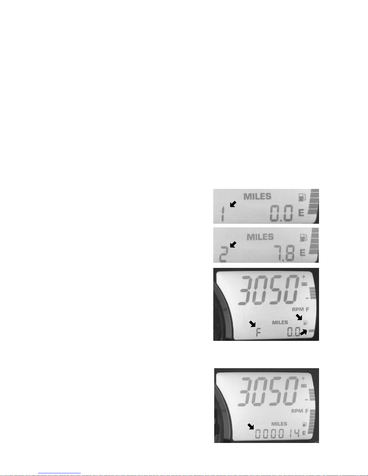
Trip Settings
Trip 1 and Trip 2 are odometers used to
check fuel mileage or to keep track of
distance traveled.
1. To reset a trip odometer to zero,
entertheTrip1orTrip2display.
2. Press and hold the SET button for
two seconds.
Trip F automatically displays if the fuel
level is low. The fuel symbol and the
last fuel bar on the MFD gauge will
blink when the fuel level reaches 1/8th
tank. The Trip F odometer records
distance traveled until enough fuel is
added to raise the level above 1/4 tank.
The fuel symbol and the fuel bar will
continue to blink until the fuel level is
above 1/4 tank. The Trip F odometer
will automatically reset to zero after
refueling.
Odometer Setting
The odometer records the vehicle’s
total distance traveled since
manufacture. The odometer cannot be
reset.
Page 43

40
FEATURES
Instrumentation
MFD Digital Display Programs
Performance Program
Clock Setting
1. While in the CLOCK display, press
and hold the SET button for five
seconds.
2. When the hour starts flashing press
the SET switch once to advance one
hour, or press and hold the SET
button to advance the hour once
every 0.2 seconds.
3. Press the MODE button to save the hour and flash the minutes.
4. Set the minutes in the same manner.
5. When finished, press the MODE button to save the new setting.
NOTE: If the MODE button is not pressed within ten seconds, the
clock will automatically save the new entry.
Engine Program
The Engine Program automatically displays the engine coolant
temperature, engine hours, electrical system voltage level and fuel
level. On machines equipped with altimeter sensor and ambient air
temperature sensors, altitude and ambient air temperature will display
as additional screens in the engine program. Press the SET button to
display the ambient air temperature and altitude screens (if equipped).
On turbo-charged models, the boost pressure screen follows these two
screens.
Air Temperature (if equipped)
The MFD displays actual air temperature.
Press and hold the MODE switch for ten
seconds to switch between standard and
metric units of measurement.
Page 44

41
FEATURES
Instrumentation
MFD Digital Display Programs
Altitude (if equipped)
The rider can calibrate the altimeter for
current atmospheric conditions. Altimeter
accuracy will be +/-300 ft. (91 m) after
adjustment.
NOTE: Press and hold the MODE switch
for ten seconds to switch
between standard and metric units of measurement. When
“ALt” displays, the program is in the metric mode.
1. Enter the Engine Program and select the altimeter display.
2. Press and hold the SET button for five seconds.
3. When the digits begin to flash, press the SET button once to
advance 50 feet (15 m), or press and hold the button to advance
100 ft. (30 m) every 0.1 seconds. Adjust t he altitude display to
within 50 ft. (15 m) of current altitude.
NOTE: The gauge reads barometric pressure and allows the rider to
compensate for daily fluctuations in air pressure. The gauge
can adjust the displayed altitude to +/- 1300 ft. (396 m) from
the preset value. It will adjust up to +1300 ft. (396 m) above
the calibrated altitude. Once the +1300 ft. (396 m) offset has
been reached, the next adjustment is -1300 ft. (396 m) from
the calibrated altitude, and 50 ft. (15 m) will be added to the
altitude each time the SET button is pressed.
4. Press the MODE button to hold the reading at the adjusted value. If
it’s not pressed within five seconds, the gauge will automatically
save the new setting.
Hour Meter
The hour meter records the total hours of
engine operation since manufacture. This
meter cannot be reset.
Engine Temperature
A thermometer measures water temperature,
giving an indication of engine temperature.
Page 45
42
FEATURES
Instrumentation
MFD Digital Display Programs
History Program
The History Program automatically displays electrical system voltage
level and fuel level.
While in the History mode, press the SET button to view maximum
vehicle speed, maximum engine rpm or the current service interval
setting. The gauge automatically logs the maximum speed and engine
rpm even if the History Program is not curre ntly displayed.
The History Program will display the history of the Maximum Speed,
Maximum RPM and Service Interval settings.
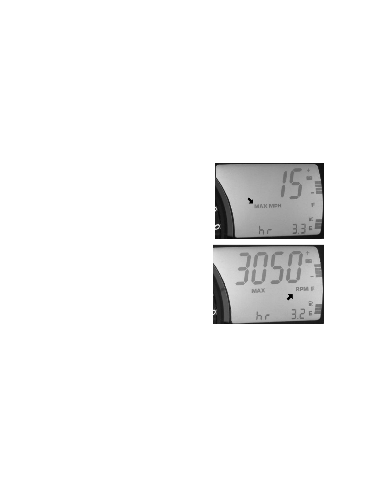
Maximum Speed/RPM Reset
While in either the MAX MPH or the
MAX RPM mode, press and hold the
SET button for three seconds to reset
the recorded maximum values for both
MPH and RPM. Both of these values
are reset at the same time. Reset the
MAX MPH/RPM values before each
run to obtain accurate readings.
NOTE: Due to electrical noise, the
MFD may occasionally
display MAX MPH/RPM
values that are not
representative of actual
values.
Page 46
43
FEATURES
Instrumentation
MFD Digital Display Programs
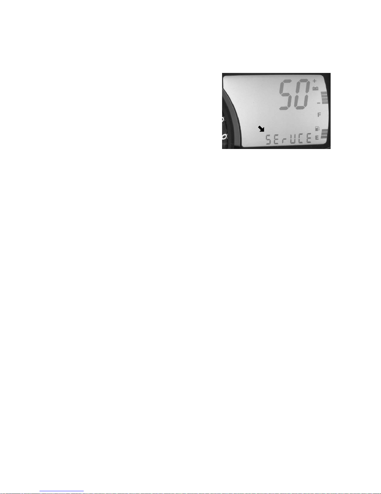
Service Interval Reminder
The gauge logs the number of engine
hours between service reminders.
When the logged hours reaches the
designated service interval (set by the
user), the gauge provides a reminder
that service is due. “SErVCE” will
flash in the odometer area and “ENG”
will flash in the icon area for five
seconds each time the vehicle is
started until the service reminder is reset.
See the maintenance charts beginning on page 88 for recommended
service intervals.
To reset the reminder at the existing interval:
1. Enter the service interval screen.
2. Press and hold the SET button for ten seconds, continuing to hold
even after the display begins to flash.
3. When the display stops flashing, release t he button. The service
interval has been reset.
To reset the reminder at a new interval:
1. Enter the service interval screen.
2. Press and hold the SET button for five seconds, until the hours
begin to flash.
3. Immediately release the button.
4. Press t he button again up to five times to advance the reminder in
50-hour increments.
NOTE: The maximum interval is 250 hours.
To disable the service interval reminder, press the SET button once
after reaching 250 hours on the display. The gauge will display
“OFF”.
Page 47

44
FEATURES
Instrumentation
MFD Battery Replacement
If the clock function of t he MFD isn’t
working properly, replace the battery .
Replacement batteries are available
from your dealer.
1. Remove the plenum from the
underside of the hood.
2. Locate the black battery
compartment (A). It has a red
wire and a brown wire with a
white stripe. It’s located about
three inches down the main
harness from the point where the
harness connects to the MFD.
3. Cut the plastic cable tie (B) from
the outside of the compartment.
4. Carefully cut the bottom of the
compartment (opposite the wires)
to separate the heat-sealed seams.
Squeeze the corners of the compartment inward so the battery (C)
is visible.
NOTE: Note the orientation of the battery before removing it. An
incorrectly installed battery will not maintain the clock.
5. Using needle-nose pliers, grasp the battery and rotate it slightly so
the leading edge of the battery is raised slightly away from the
battery holder. Pull the battery out gently.
NOTE: The battery will not come out of the holder unless the leading
edge of the battery is raised. Hold the battery compartment,
not the wires, while removing the battery. Pulling on the
wires will separate them from the battery holder.
A
B
C
Page 48

45
FEATURES
Instrumentation
MFD Battery Replacement
6. Install a new battery with fingers only.
7. Seal the end of the battery compartment using high strength
double-sided tape between the two compartment halves or high
strength single-sided tape around the outside of the compartment.
8. Make sure the taped seam of the compartment faces the downward
side of the wire harness.
9. Install a cable tie to secure the compartment to the wire harness in
the same location where the previous cable tie was located. Make
sure the battery wires are not stretched tight.
Gauge Cleaning
1. Wipe the gauge face as needed using a clean cloth and a mild soap
and water solution. Wipe dry with clean, soft cloth.
2. Clean the back side of the gauge using a clean cloth and a mild
soap and water solution. Do not remove the electrical connectors
or protective rubber boot. Do not spray the back side of the gauge
or the wire harness with a pressure washer or other water source.
CAUTION
To prevent damage to the lens, do not use alcohol for cleaning.
Do not allow chemicals or sprays to come into contact with the
lens. Immediately clean off any gasoline that splashes on the
gauge during refueling.
Page 49
1
2
4
3
46
THE PERFECT FIT
IQ Front Suspension Adjustments
Independent Front Suspension (IFS)
Break in the suspension for approximately 150 miles (240 km) before
making any fine-tuning adjustments.
Settings will vary from rider to rider, depending on rider weight,
vehicle speed, riding style, and trail conditions. We recommend
starting with factory settings and then customizing each adjustment
individually to suit rider preference. The snowmobile should be
methodically tested, one change at a time, under the same conditions
(trail and snow conditions, vehicle speed, riding position, etc.) after
each adjustment until the best ride is achieved.
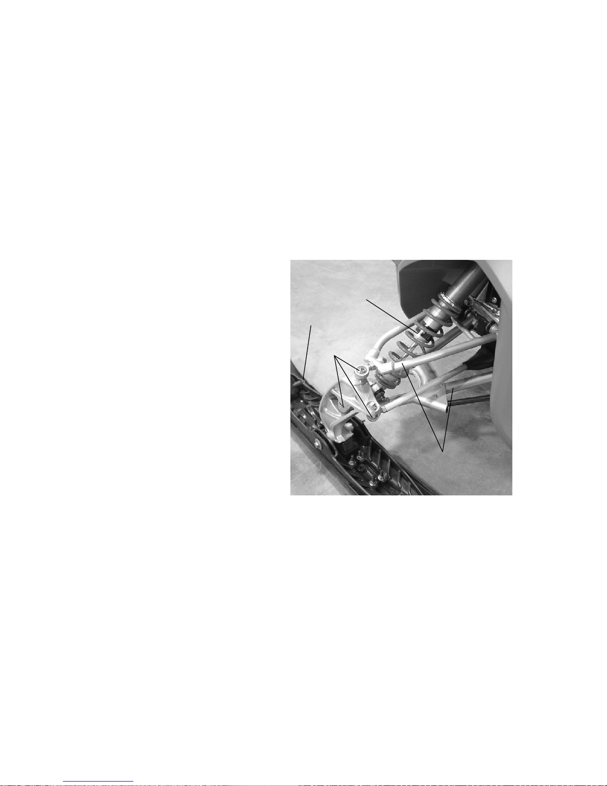
IFS Components
1. Skis
2. Front shocks and springs
3. Rod ends
4. A-arms
IFS Adjustment Options
S Shock damping (if equipped
with ArvinMeritor MPV
Select shocks)
S Front shock spring preload
S Optional springs
S Optional shock valving
(Switchback)
S Toe (ski alignment) (see page 126)
S Camber (see your dealer)
Page 50

47
THE PERFECT FIT
IQ Front Suspension Adjustments
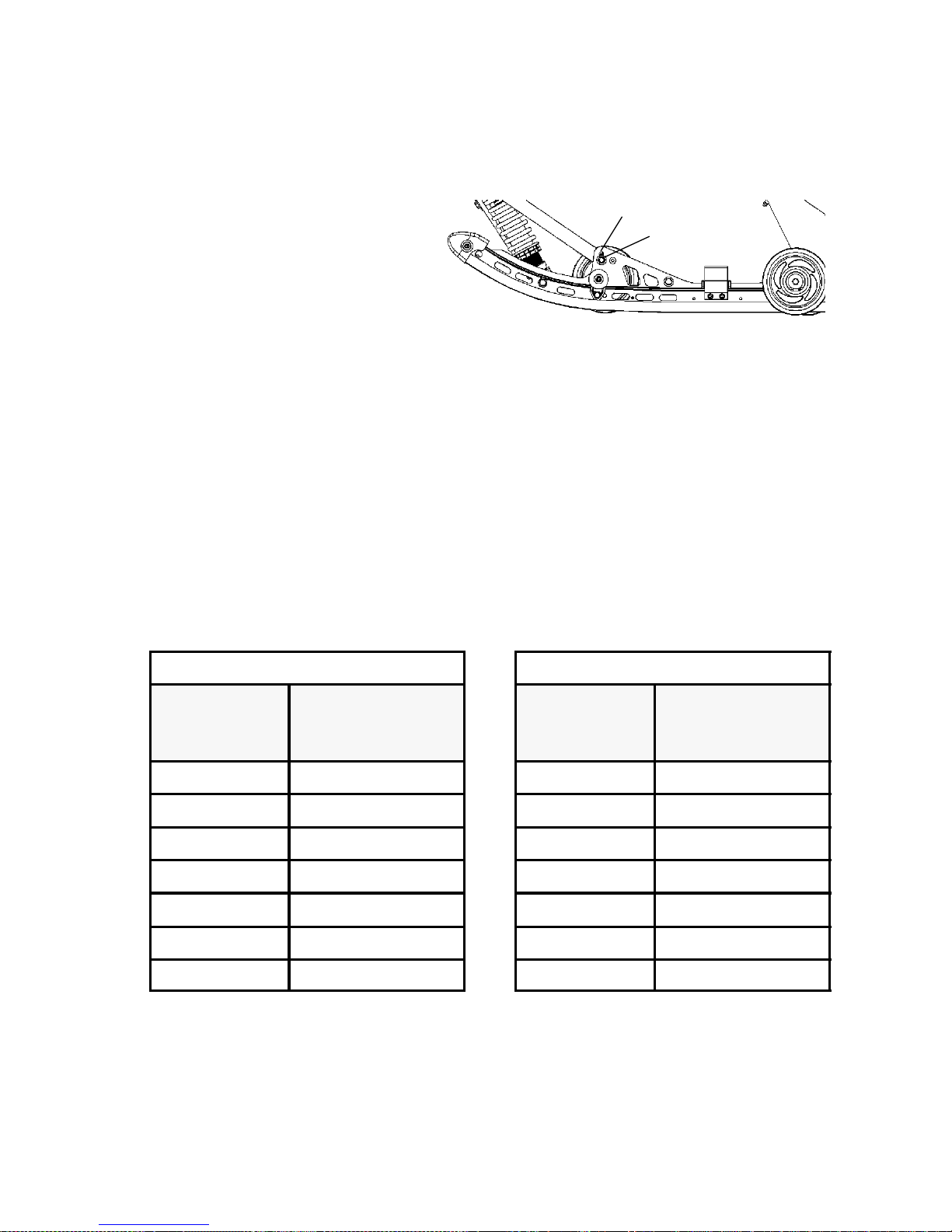
Shock Damping
Adjustments to the compression stiffness
of ArvinMeritor MPV Select shocks
can be made by turning the adjustment
screw (+) located near the base of the
shock. This adjustment is the easiest to
perform and it should be considered
first.
The factory setting for this shock is the
softest position, with the adjusting screw
all the way out (counterclockwise). If
bottoming occurs, turn the screw
clockwise to increase compression and
stiffen the ride.
When adjusting these shocks, we recommend that you turn the screw
only 1/4 turn at a time, then t est ride. Always adjust both shocks
equally.
Front Shock Spring Preload
The factory preload setting should be appropriate for most riders and
conditions. Please see your Polaris dealer for assistance before
attempting to adjust preload.
Increasing the spring preload too much may adversely affect the
handling of the snowmobile and the performance of the rear
suspension.
Decreasing the spring preload too much may allow the upper spring
retainer to fall off.
+
Page 51

48
THE PERFECT FIT
IQ Front Suspension Adjustments
Shock Valving (Switchback)
The shocks can be revalved if spring preload alone isn’t sufficient and
further adjustment is desired to control suspension stiffness.
WARNING
Changing shock valving requires special tools and a sound
knowledge of mechanical theory, tool use, and shop procedures
to perform the work safely and correctly. Shocks contain
high-pressure nitrogen gas. Use extreme caution when handling
high-pressure service equipment. We recommend that this work
be performed by a Polaris dealer.
Front Springs
The front springs can be changed if spring preload alone isn’t sufficient
and further adjustment is desired to control suspension stiffness. See
your Polaris dealer for more information.
Page 52

49
THE PERFECT FIT
Rear Suspension Adjustments
Rider weight, riding style, trail conditions, and vehicle speed all affect
suspension action.
Each rear suspension can be adjusted to suit rider preference and
deliver excellent performance for a given set of conditions. However,
all suspension designs and adjustments involve a compromise, or
trade-off. For example, a suspension set up for snow-cross racing
would provide a very stiff ride on the trail. A suspension set up for
trail riding would bottom out harshly on a snow-cross course.
Make adjustments t o one area at a time so you can evaluate the change.
For further assistance, see your dealer.
Suspension Performance Tips
S Rider weight usually determines the position at which the spring pre-
load should be set. However, t his may vary with riding style. With
a little experimentation, each rider can find a preferred set-up. These
adjustments are easy to make, involve very little time or effort, and
greatly affect the ride.
S In deep snow, a new rail slide will offer improved performance over
a worn slide. It can also improve top speed.
S Polaris offers track kits for improved flotation in deep snow. See
your dealer for assistance.
NOTE: Keep the suspension pivot points lubricated. This will reduce
moisture and rust build-up and ensure proper function of the
suspension components. Grease rear suspension pivots
before adjusting the rear suspension. Refer to Suspension
Maintenance beginning on page 98.
Page 53
50
THE PERFECT FIT
Switchback Rear Suspension
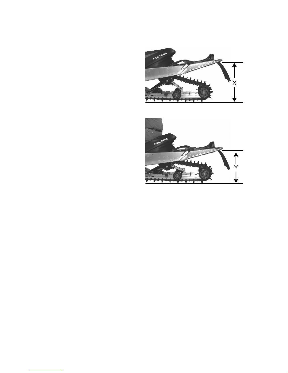
Initial Spring Preload Setting (Sag Method)
To set up the rear suspension
torsion spring preload, measure
the distance between the ground
and rear bumper. This is
measurement X.
Take this measurement with no
rider and with the rear suspension
at full extension.
NOTE: The rear bumper may
need to be lifted
upward slightly to fully
extend the suspension.
Next, have the rider drop down
hard on the seat and bounce up
and down several times,
collapsing the rear suspension.
With the rider seated, measure the
distance between the ground and
the rear bumper at the exact
location used for measurement X.
This is measurement Y.
To determine sag, commonly referred to as ride-in, subtract
measurement Y from X (Sag=X-Y). Adjust sag by rotating the torsion
spring preload cams l ocated on the rear torque arm. See illustration.
The ideal amount of sag for this rear suspension is five inches (12.7
cm) (X-Y=5 in./12.7 cm).
If the rear suspension rides in less than four inches or more than six
inches with the torsion spring preload cams at their maximum range of
adjustment, optional torsion springs (softer or stiffer, respectively) may
be required. This is only an initial setup, and final spring preload may
vary based on rider preference and riding conditions.
Page 54
51
THE PERFECT FIT
Switchback Rear Suspension
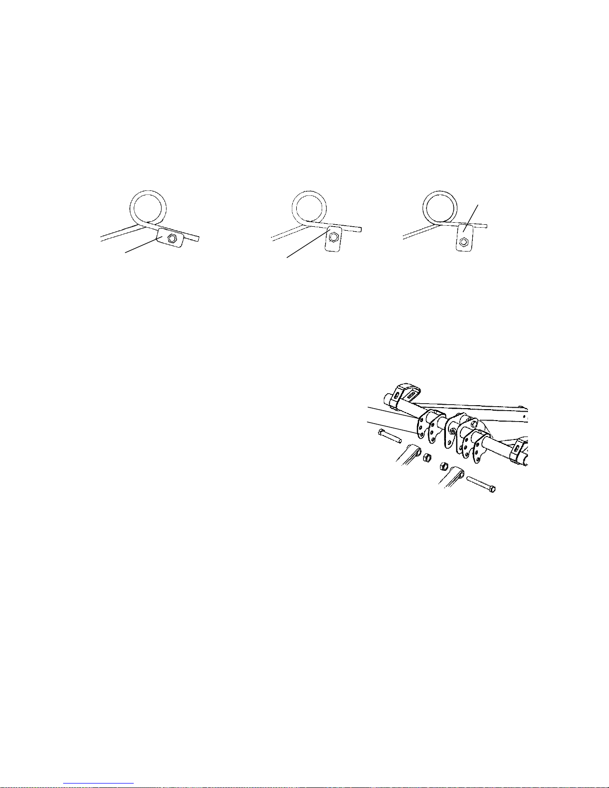
Rear Torsion Spring Tension
To adjust rear torsion spring tension, rotate the three-position cam
using the engine spark plug tool.
Different rate torsion springs are available if a firmer ride is desired.
Contact your dealer for more information.
A. Soft Tension - long end of cam to front
B. Medium tension - short end of cam up
C. Firm tension - long end of cam up
Limiter Strap Position
The following information is
provided only as a guideline to be
used for initial suspension set-up.
Your set-up may vary based on your
desired riding style.
A. Limiter strap in high position
increases ski pressure
B. Limiter strap in low position
decreases ski pressure
B
A
C
A
B
Page 55

52
THE PERFECT FIT
Switchback Rear Suspension
Rear Track Shock Compression Damping
A. Turn rear track shock screw clockwise to stiffen compression.
B. Turn the rear track shock knob clockwise for a softer ride.
C. Turn the rear track shock knob counter clockwise for a stiffer ride.
B
C
A
Page 56

L
53
THE PERFECT FIT
Switchback Rear Suspension
Rear Shocks
When adjusting, we recommend that you turn the adjuster slightly,
then test ride. The recommended setting for this shock is eight (8)
clicks counter-clockwise.
FOX Zero Pro XC Shock
The FOX Zero Pro XC shock is standard on the Switchback model.
Turn the adjustment knob (L) on the shock reservoir to make
adjustments to the compression damping.
Page 57

54
THE PERFECT FIT
FAST M-10 Rear Suspension Adjustments
The M-10 suspension has been designed to be very sensitive to rider
weight. Changes in rider weight of 25 lbs. (11 kg) or more might
require appropriate changes in settings. The following information has
been compiled to assist you in tuning your M-10 suspension to its
maximum potential and achieve the best possible ride. Please take the
time to read and understand all the possible adjustments available with
this suspension.
Static Sag and Ride Height Settings
Static sag describes the difference in height of the rear bumper from the
suspension’s fully extended position to its loaded height, with the rider
seated on the snowmobile. Too much sag will result in bottoming, and
too little sag will result in reduced rider comfort.
Sag is used to control ride quality and rebound travel. On this
suspension, sag is controlled by two settings, the full range adjuster
(FRA) position and the rear spring preload.
1. To check sag, raise the rear bumper until the suspension is fully
extended (the rear shock will not extend any further). Measure the
distance from the ground to the bottom of the bumper (dimension
X) as shown in the illustration. Record the measurement.
2. Have the rider sit on the snowmobile and bounce up and down on
the seat a few times to set in the suspension. While the rider
remains seated, m easure the distance from the ground to the top of
the bumper (dimension Y) and record it.
Page 58

55
THE PERFECT FIT
FAST M-10 Rear Suspension Adjustments
Static Sag and Ride Height Settings
3. Subtract Y from X and you will have the SAG setting (X - Y = sag
setting. Example: 21 - 17 = 4). The correct amount of SAG for
the FAST M-10 rear suspension is 3-4 inches (8-10 cm).
If the measured sag is incorrect, adjust the FRA position and rear
spring preload. See pages 56--57.
X
Y
Page 59

56
THE PERFECT FIT
FAST M-10 Rear Suspension Adjustments
Static Sag and Ride Height Settings
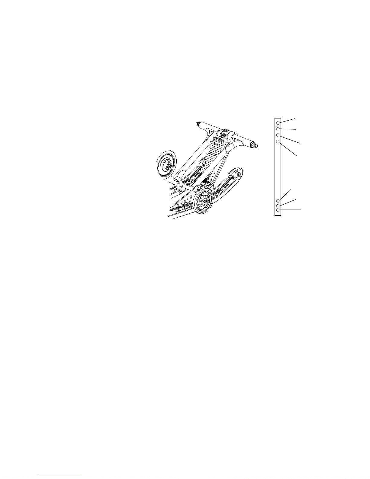
FRA Position
The FRA setting is the primary rear suspension adjustment. It will have
the MOST effect on the rear suspension performance. To adjust the
FRA:
1. Refer to the initial set-up reference chart (located under the hood of
your snowmobile or on page 59) to determine the desired FRA
position.
2. To adjust, loosen the hex bolts (A) attaching the rear lower shock
cross shaft to the rail beam.
3. Using a 9/16” wrench, loosen the jam nuts (B) on the preload
bolts.
4. Adjust the preload bolts (C) to the desired FRA position.
5. Tighten the jam nuts.
NOTE: Make sure the preload bolt contacts the slide block before
tightening the jam nut.
6. Tighten the hex bolts and torque to 35 ft. lbs. (47 Nm).
NOTE: When the M-10 suspension is new , it will take from 25 to 200
miles (40-300 km)to properly break in the springs and
shocks, at which time the suspension will be softer and may
require FRA re-adjustment.
A
B
C
Page 60

57
THE PERFECT FIT
FAST M-10 Rear Suspension Adjustments
Static Sag and Ride Height Settings
Rear Spring Preload
If FRA position alone does not allow the setup of the proper amount of
sag, the center retainer of the rear track shock can be replaced with
optional retainers to adjust the preload and change the sag. See your
Polaris dealer for assistance.
OPTIONAL RETAINERS
Retainer Insert
Part Number
Retainer Part
Number
Preload Sag
5436109
5135077
(standard on
M10-128)
Least Most
5134923 Middle Middle
5135080
(standard on
M10-136)
Most Least
NOTE: Whenever ordering any of the retainers listed in the chart,
always order the retainer insert as well. The insert is not
removeable once installed, so a new insert is needed when
installing a new retainer.
Page 61
58
THE PERFECT FIT
FAST M-10 Rear Suspension Adjustments
Static Sag and Ride Height Settings
Ski Pressure
Ski pressure is set at the factory to deliver the optimum balance
between ride and handling. If a rider prefers more ski pressure for
improved steering performance, adjustments can be made to the front
limiter strap and front arm mount.
1. Determine if the rider
prefers comfort or
control. Lean toward the
#4 setting for comfort
and toward the #3
setting for aggressive
riding.
2. For full hole
adjustments,
remove the 5/16”
nut and flat washers
from the lower
attachments of the
limiter straps and relocate
the straps to the desired position
(i.e. move from position 4 to 3). Replace the nut and washer.
Tighten securely.
3. For half-hole increments (such as 3/4), the limiter straps have slots
at the upper pinch bolt. These slots allow the bolts to be loosened
(rather than removed) for half--step adjustments. Re-- tighten the
pinch bolts.
4
3
2
1
3
4
2
Page 62
59
THE PERFECT FIT
FAST M-10 Rear Suspension Adjustments
Static Sag and Ride Height Settings
Ski Pressure
4. There are also two
front arm mounting
holes in the slide rail
that can adjust ski
pressure. The lower
hole (A) increases ski
pressure while the upper
hole (B) decreases ski pressure.
NOTE: By design, the BIASED COUPLE design of the M-10
suspension displaces the rear arm as the front arm is
compressed. This means that when you raise the front
limiter strap, at some point you will collapse the rear
suspension arm, which will affect SAG height and reduce
rear suspension travel.
Initial M-10 Suspens io n Set-up Charts
These charts are a guideline to be used for initial suspension set-ups.
Your set-up may vary based on your desired riding style.
M10-128
Rider Weight
with Gear
(lbs.)
Suggested FRA
Range (Lower
Number is Softer)
Under 100 1to11/2
100-150 1 1/2 to 2
150-200 2to21/2
200-250 2 1/2 to 3
250-300 3to31/2
300-350* 3 1/2 to 4
350+* 4to5
M10-136
Rider(s)
Weight with
Gear (lbs.)
Suggested FRA
Range (Lower
Number is Softer)
Under 100* 1to11/2
100-150* 1 1/2 to 2
150-200* 2to21/2
200-250 2 1/2 to 3
250-300 3to31/2
300-350 3 1/2 to 4
350+ 4to5
*You may prefer an optional rear track middle spring retainer. See page 57.
A
B
Page 63
60
THE PERFECT FIT
Handlebar Adjustments
Use the RIDER SELECT feature to adjust handlebar position. See
page 31. Use the following steps to adjust handlebar angle at the
handlebar block.
1. Remove the handlebar cover (A)
to expose the handlebar and the
four adjuster block bolts (B).
NOTE: If equipped, remove the
mountain bar (C).
2. Using a 7/16″ (11 mm) wrench,
loosen the four nuts (D) on the
bottom of the adjuster block (turn
handlebar to left or right for
access to back nuts).
NOTE: If necessary, pry the
blocks apart with a
screwdriver.
3. Adjust the handlebar to the desired height. Be sure handlebars,
brake l ever and throttle lever operate smoothly and do not hit t he
gas tank, windshield or any other part of the machine when turned
fully to the left or right.
4. Torque the handlebar adjuster block bolts to 11-13 ft. lbs. (15-18
Nm).
NOTE: Torque the front bolts first.
5. Reinstall the handlebar cover.
A
B
D
C
Page 64

61
THE PERFECT FIT
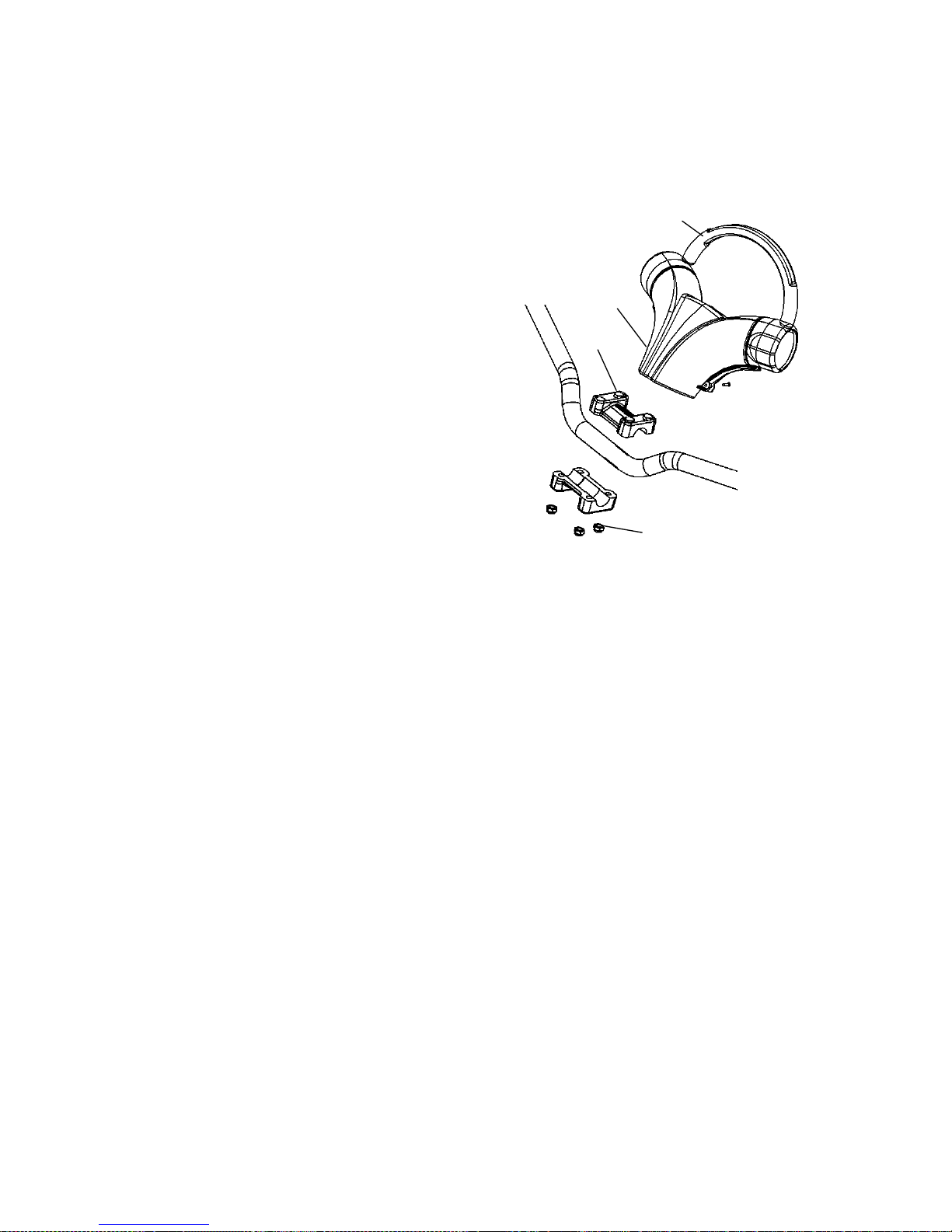
Passenger Grab Handle Adjustment (Touring)
On some Touring models the position of the
passenger grab handles can be adjusted for
rider preference. To make an adjustment:
1. Unscrew and remove the knob
assemblies (A) that secure the grab
handles.
2. Reposition the grab handles to one of the
three available positions on the grab
handle tube between the operator seat
and the passenger seat.
3. Reinstall the knob assemblies and
tighten securely.
Accessories
Polaris offers a wide range of accessories for your snowmobile to help
make each ride more enjoyable.
Use only Polaris parts and accessories on your Polaris snowmobile.
Use of unapproved parts and accessories may result in:
S Non-compliance with government/industry requirements
S Voiding of warranty
S Injury to self or others
This applies, but is not limited to the following areas: brakes, clutches,
fuel systems, and exhaust systems.
NOTE: Exhaust systems are critical safety areas that must use
approved Polaris parts. Please see your Polaris dealer for
service.
A
Page 65

62
THE PERFECT FIT
Traction Products
Studs
Before equipping your snowmobile with traction products, be aware of
the laws in your area pertaining to the use of traction products.
Use only Polaris traction products on your snowmobile. Track
warranties are void if track damage or failure results from improper or
excessive stud installation or the use of non-Polaris traction products.
See your dealer about installing studs and/or carbides.
CAUTION
Always install wear strips before installing studs. Failure to install
wear strips may result in cooler or tunnel damage. See page 63.
Never add shims to the wear strip. Track damage will result
because of lack of clearance between upper carrier wheels and
track.
Use of studs longer than the recommended length on machines
equipped with center coolers will result in center cooler damage
or damage to the tunnel.
Track studding will enhance braking control on hard-packed snow or
ice, but extreme caution is still required on such surfaces. Steering
ability may be reduced on hard-packed snow or ice.
When studded tracks are used, increased wear to the brake pads will
result from increased braking. Extended-wear brake pad kits are
available. See your dealer.
CAUTION
Aggressive studding patterns may require grinding protruding
stud bolts flush to prevent idler wheel damage. Maintain track
tension on studded tracks on the tight side of the spec to prevent
heat exchanger damage. Center of stud must be at least 1 1/8″
(2.86 cm) from the outside edge of the track.
Page 66

63
THE PERFECT FIT
Traction Products
n
Carbide Skags
A skag is a replaceable bar attached to the underside of the ski to assist
in turning the snowmobile and to prevent ski wear caused by contact
with roads and other bare terrain. Use carbide skags with studded
tracks to help maintain proper vehicle steering and control. See page
127.
If your snowmobile has carbide skags, it may be necessary to add track
studs to maintain proper vehicle control. Maintain a proper balance
between the number of studs and the length of carbide on the skags
(the more studs you use, the longer the carbide on the skags should be).
See your dealer’s track studding chart.
Wear Strips
To avoid excessive tunnel wear, tunnel wear strips must be installed
whenever track studding is used.
Install the appropriate wear strip kit. See your dealer.
Wear strips are designed for a specific stud length. See your dealer’s
studding chart for recommended traction accessories.
CAUTION
Whenever wear strips are relocated, be sure there’s adequate
stud clearance to the heat exchangers. Lack of clearance may
result in damage to heat exchangers.
Page 67

64
PRE-RIDE INSPECTIONS
Pre-Ride Checklist
Inspect all items on the checklist for proper operation or condition
before each use of the snowmobile. Procedures are outlined on the
referenced pages. Look for a checkmark (n) on the referenced pages
to locate the pre-ride inspection items.
Item
SeeP
age
Drive Belt Condition 117, 117
Steering System 66
Park Brake Lock/Brake Lever/Brake System 67, 68, 111
Throttle Lever 65, 81
Throttle Safety Switch 65, 80, 83
Auxiliary Shut-Off Switch (Engine Stop Switch) 71, 83
Ignition Switch 71, 83
Taillight/Brakelight/Headlight 71
Coolant Level 106
Gearcase Oil Level 100
Engine Oil Level 92
Foam Oil Breather Element 97
Suspension Mounting Bolts 70
Skags (Wear Bars) 63, 127
Ski Saddle and Spindle Bolts 70
Hood Straps/Latches 66
Seat Latches 65
Rear Wheel Idler Bolts 123, 70
Track Alignment/Condition 69, 124
Rail Slide Condition 124
Oil Level (check before operating if vehicle was tipped over) 72
Page 68

65
PRE-RIDE INSPECTIONS
Check Before Starting the Engine
WARNING
Worn, damaged, or malfunctioning components may cause
serious injury or death. Before starting the engine, check all
components to be sure of proper operation.
Read and Understand Your Owner’s Manual
Read the Owner’s Manual completely and refer to it often. The manual
is your guide to safe and enjoyable snowmobiling experience.
n Throttle Lever
The throttle and brake are the primary controls of your snowmobile.
Always make sure both are functioning properly.
Squeeze the throttle lever to make sure it compresses evenly and
smoothly. When released, the lever should immediately return to the
idle position without binding or hesitation. If the throttle does not
function smoothly, or if you discover excessive lever freeplay, DO
NOT start the engine. Have the throttle serviced immediately.
n Throttle Safety Switch
Test the throttle safety switch system before the snowmobile is
operated. See page 80 for procedure.
n Seat Latches
Ensure that the seat latches are securely in place before every use of the
snowmobile.
Page 69

66
PRE-RIDE INSPECTIONS
Check Before Starting the Engine
n
Hood Latches
The hood of the snowmobile protects the operator from moving parts
as well as aiding in sound emission control and other functions. Under
no circumstances should your snowmobile be operated with the hood
open or removed. Always ensure that the hood straps are in good
condition and that the latches are securely in place before operating the
snowmobile.
n Steering System
WARNING
Ice and snow build-up may interfere with the steering of your
snowmobile, resulting in serious injury or death. Keep the
underhood area free of snow and ice.
Before driving, manually turn the skis to the left and right to be sure
ice and snow are not interfering with full left and right steering. If
difficulty is encountered, remove ice and snow build-up that may be
obstructing the steering linkage.
NOTE: If your snowmobile is equipped with RIDER SELECT,
perform this check in both the full up and full down steering
positions.
Page 70

67
PRE-RIDE INSPECTIONS
Check Before Starting the Engine
n
Brakes
Always check the
following items for proper
operation before starting
the engine.
Brake Lever Travel
Squeeze the brake lever.
It should move no closer
to the handgrip than 1/2″ (1.3 cm).
A smaller distance indicates low brake fluid level or air in the
hydraulic system. Refer to the brake bleeding information on page 113.
Lever Feel
If the brake lever feels “spongy” when squeezed, check the brake fluid
level and condition. Add fluid as needed. See page 112.
Check for the presence of air in the fluid system. See page 113 for more
information, or see your dealer for service.
WARNING
Continued use of “spongy” brakes may cause a complete loss of
brakes, which could result in serious injury or death. Always have
the brakes serviced at the first sign of sponginess.
1/2″
(1.3 cm)
Page 71

D
C
A
B
68
PRE-RIDE INSPECTIONS
Check Before Starting the Engine
n
Park Brake Lever Lock
Use the park brake lever lock only when you want the snowmobile to
remain stationary; for example, when parked on an incline for a period
of five minutes or less.
A. Brake Lever
B. Park Brake Lever Lock
C. Master Cylinder
Reservoir / Cover
D. Fluid Level Indicator
Lock Engagement
To engage the lock, squeeze the
brake lever tightly and push
forwardonthelock. Holdthe
lock forward while releasing the
brake lever .
NOTE: If the brake lever is squeezed tightly enough, the lock will
move freely into place. Do not force the lock or it may break.
The park brake light on the gauge, will light up if the park brake lever
lock is set while the engine is running. It will also be lit when the
service brake is in use. If the park brake light does not come on when
the park brake or service brake is in use, have it serviced by your
dealer.
Lock Release
To release the lock, squeeze the brake lever tightly. The lock will
return to the unlock position.
WARNING
If the park brake lever lock is partially or entirely engaged while
riding, the brakes may overheat, resulting in brake damage. In
extreme cases it could cause a fire, which could result in serious
injury or death. Always ensure that the lever lock is completely
disengaged before operating the snowmobile.
Page 72

69
PRE-RIDE INSPECTIONS
Check Before Starting the Engine
n
Track Inspection
WARNING
Operating the snowmobile with a damaged track increases the
possibility of track failure, which could cause loss of control
resulting in serious injury or death. Always inspect the track for
damage before using the vehicle.
Use of traction products such as studs increases the possibility of track
damage and/or failure. Driving at high speeds for extended periods of
time in marginal lubrication could severely damage track rods, break
track edges and cause other track damage. Examples of marginal
lubrication would include frozen bodies of water without snow cover,
icy trails, and no-snow conditions.
NOTE: Track damage or failure caused by operation on ice or poor
lubrication conditions voids the track warranty.
Page 73

70
PRE-RIDE INSPECTIONS
Check Before Starting the Engine
n
Suspension Inspectio n
Loose nuts and bolts can reduce your snowmobile’s reliability and
cause needless repairs and down time. Before beginning any
snowmobile trip, a visual inspection will uncover potential problems.
Check the following items on a weekly basis or before any long trip.
Item Check Page
Suspension mounting bolts Tightness --
Rear idler wheel bolts Tightness 123
Rear idler adjusting bolt locknuts Tightness --
Torque arm bolts Tightness --
Carrier and bogie wheel bolts Tightness --
Front torque arm limiter strap Condition --
Rail slide Condition 124
Track Tension 122
All rear suspension components Lubrication 98
Ski runner/skag Condition --
Ski spindle bolts Tightness --
Tie rod end nuts Tightness --
Page 74

71
PRE-RIDE INSPECTIONS
Check After Starting the Engine
n Engine Stop Switch
Check the auxiliary shut-off switch for proper operation. Push the
switch down to stop the engine. Pull it up to allow restarting.
n Ignition Switch
Make sure the engine stops when the ignition switch is turned to OFF.
n Lighting
Check the headlight (high and low beam), taillight, and brake light.
Replace burned out lamps before operating.
n Mirror Adjustment
If equipped, adjust your mirrors so they can be used to their full
advantage.
n Operating Area
Before driving away, check your surroundings. Be aware of obstacles
and make sure bystanders are a safe distance from t he snowmobile.
Page 75

72
PRE-RIDE INSPECTIONS
n Tip-Over Inspections
In the event of a tip-over or rollover, check the oil level before
operating the snowmobile.
CAUTION
Failure to check the oil after a tip-over can result in serious
engine damage. Always check the oil level before operating a
snowmobile that has tipped over or rolled over.
NOTE: In the event of a tip-over or rollover, the engine will stop. To
restart the engine, turn the key to the OFF position, then
restart.
WARNING
Operating a snowmobile with accident damage can result in
serious injury or death. Do not operate the snowmobile if vehicle
components have been damaged in a collision or tip-over. Have
the snowmobile inspected by an authorized Polaris dealer.
Page 76

73
OPERATION
Fuel Safety
WARNING
Gasoline is highly flammable and explosive under certain
conditions.
S Always exercise extreme caution whenever handling gasoline.
S Always refuel outdoors or in a well-ventilated area.
S Always turn off the engine before refueling.
S Do not overfill the tank. Do not fill the tank neck.
S Do not smoke or allow open flames or sparks in or near the
area where refueling is performed or where gasoline is stored.
S If gasoline spills on your skin or clothing, immediately wash it off
with soap and water and change clothing.
S Never start the engine or let it run in an enclosed area. Engine
exhaust fumes are poisonous and can cause loss of consciousness or death in a short time.
WARNING
The engine exhaust from this product contains chemicals known
to cause cancer, birth defects or other reproductive harm.
Operate this vehicle only outdoors or in well-ventilated areas.
Page 77

74
OPERATION
Break-In Period
The break-in period for your new Polaris snowmobile is the first 500
miles (800 km) of operation. No single action on your part is as
important as following the procedures for a proper break-in. Careful
treatment of a new engine and drive components will result in more
efficient performance and longer life for these components.
CAUTION
Excessive heat build-up during the first 500 miles (800 km) of
operation will damage close-fitting engine parts. Do not operate at
full throttle or high speeds for extended periods during the
break-in period.
Use of non-recommended oil may cause serious engine damage.
Always use the recommended oil for your Polaris snowmobile.
1. Fill the fuel tank with the recommended fuel. See page 79.
2. Check the oil level in the oil tank. See page 92. Add oil if
necessary to maintain at the recommended level.
3. Drive slowly at first. Vary the throttle positions. Do not operate at
sustained idle.
4. Perform regular checks on fluid levels, controls and areas outlined
on the daily pre-ride inspection checklist. See page 64.
5. During the break-in period, change both the oil and the filter at 500
miles or before seasonal storage, whichever comes first.
Page 78

75
OPERATION
Starting the Engine
WARNING
Before starting the engine, always refer to all safety warnings
pertaining to snowmobile operation. Never start your snowmobile
without checking all components to be sure of proper operation.
See Check Before Starting the Engine beginning on page 65.
Do not depress the throttle until the engine starts.
1. Turn the key to the ON position.
2. Pull the engine stop switch up to the RUN position.
CAUTION
To avoid injury and/or engine damage, do not operate the electric
starter while the engine is running.
3. Turn the key to START to crank the engine. Release the key to the
ON position when the engine starts.
4. Repeat the cranking procedure as needed until the engine starts.
Page 79

76
OPERATION
Emergency Starting
If the battery is too weak to start the engine, and a battery charger is
not available, the engine can be started using jumper cables and a
charged battery from another vehicle. Carefully read and follow the
instructions below.
WARNING
Improperly connecting or disconnecting jumper cables can result
in an explosion and cause serious injury or death. When
connecting jumper cables, always connect the negative (usually
black) cable last. When removing jumper cables, always
disconnect the negative (usually black) cable first.
WARNING
Loose-fitting clothing can get caught in the engine when the
vehicle is running with the hood open. This can cause serious
injury or death. Remove or control all items that could catch in
the engine, including scarves, gloves, jackets and clothing straps
and hooks.
NOTE: If a car or truck battery will be used to jump start the
snowmobile, turn the engine off. A running engine will put
out too much electrical current for the snowmobile battery.
NOTE: Never attempt to jump start a discharged battery that is
frozen.
1. Always wear eye protection when jump starting your vehicle.
2. Keep bystanders away from the vehicles.
3. Perform the emergency starting procedure in a well-ventilated area.
4. Position the vehicles close enough for the jumper cables to reach
easily between the batteries, but do not allow the vehicles to touch
each other.
5. Lock the parking brakes on both vehicles to prevent accidental
movement.
6. Open the hood and remove the left side panel.
7. Decide which of the jumper cables will be positive (usually red or
yellow) and which will be negative (usually black).
NOTE: Never connect a jumper cable to the fuel system or fuel lines.
Page 80

77
OPERATION
Emergency Starting
8. Pull back the red plastic boot covering the positive terminal of the
weak battery. Connect one end of the positive jumper cable to the
positive terminal of the weak battery.
9. Connect the other end of the positive jumper cable to the positive
terminal of the charged battery.
NOTE: Make sure that the end of the negative cable by the weak
battery is not contacting the snowmobile battery or chassis.
10. Connect the other negative end of the jumper cable to the negative
terminal of the charged battery.
11. Connect the end of the negative jumper cable by the weak battery
to the CHASSIS of the snowmobile. There may be a small spark
when this is done, but this is normal.
NOTE: Always be sure that the jumper cables do not interfere with
the belts, pulleys or clutches on either vehicle.
12. Make sure that the engine stop switch is in the UP position.
13. Attempt to start the vehicle.
14. If the engine does not turn over (crank over), wait 30 to 60 seconds
and attempt to start the engine again. If the engine does not start,
wait another 1 to 2 minutes and attempt to start the engine again.
15. If the engine still does not start, try adjusting the clips on the
jumper cable ends to ensure that they have a good electrical
connections. Repeat step 14.
16. If the engine still does not start, remove the jumper cables as
outlined in step 17 and transport the snowmobile to an authorized
Polaris dealer for service.
17. Carefully remove the jumper cables in this order:
A. Remove the negative end of the jumper cable from the
snowmobile chassis.
B. Remove the negative end of the jumper cable from the
charged battery.
C. Remove the positive end of the jumper cable from the
charged battery.
D. Remove the positive end of the jumper cable from the weak
battery.
18. Reinstall the left side panel.
19. Close and secure the hood.
Page 81

78
OPERATION
Track Warm-Up
WARNING
A loose track or flying debris could cause serious injury or death.
Stand clear of the front of the machine and the moving track.
Never hold the snowmobile up or stand behind it while warming
up the track. Do not use excessive throttle during warm-up or
when the track is free-hanging. Be sure the rear support is
stable.
WARNING
Use of traction products such as studs, ice growsers, etc. will
increase the possibility of track damage and/or failure. This could
cause loss of control, resulting in serious injury or death. Always
inspect for track damage before operating the snowmobile.
Follow these steps to ensure
proper warm-up of the engine,
drive train and track.
1. Use an appropriate stand to
securely support the rear of
the snowmobile at the rear
bumper. The track should be
approximately 4″ (10 cm) off
the ground.
2. Start the engine and allow it
to warm up two to three
minutes.
3. Depress the throttle abruptly and allow the track to rotate several
revolutions.
NOTE: It will take longer to warm up the track sufficiently during
colder outdoor temperatures.
4. Release the throttle, apply the brakes, shut off the engine and lower
the snowmobile to the ground.
5. Grasp the skis by their front loops and move them from side to side
to loosen snow and ice.
Page 82

79
OPERATION
Fuel
For peak performance, Polaris recommends the use of 91 octane or
higher fuel. Although 87 octane fuel is usable, some engine
performance will be lost and fuel economy will decrease. Do not use
fuel lower than 87 octane.
CAUTION
Operating with obstructed fuel systems will result in serious
engine damage. Perform maintenance as recommended.
Damage to the fuel pump will occur if the snowmobile is operated
with an empty fuel tank. Do not allow the snowmobile to run out
of fuel. Always refuel when the level is low.
Prolonged exposure to petroleum based products may damage
paint. Always protect painted surfaces when handling fuel.
Fuel Level
The fuel symbol and the last fuel bar on the MFD gauge will blink
when the fuel level reaches 1/8th tank. There will be approximately
one gallon of fuel remaining. Refuel as soon as possible. Do not allow
the snowmobile to run out of fuel.
Fuel System Deicers
If you use non-oxygenated fuel, Polaris recommends the regular use of
isopropyl-based fuel system deicer. Add one to two ounces per gallon
(8-16 ml per liter) of gasoline t o prevent engine damage resulting from
fuel system icing and lean fuel mixtures. Never use deicers or
additives containing methanol. Polaris also recommends the use of
Carbon Clean Plus. See page 133 for the part numbers of Polaris
products.
If you use oxygenated fuel containing ethanol, additional alcohol
deicers or water absorbing additives should not be used.
Page 83

80
OPERATION
n Engine Stop Switch
Push down on the engine stop
switch (L) to ground out the
ignition and stop the engine
quickly. Pull the switch up t o the
RUN position to allow restarting.
n Throttle Safety Switch
The throttle safety switch is designed to stop the engine whenever all
pressure is removed from the throttle lever and the throttle cable or
valves do not return to the normal closed position.
WARNING
Operating the snowmobile with a faulty throttle safety switch can
result in serious injury or death in the event of an accident. If the
throttle safety switch does not shut off the engine during a throttle
system malfunction, immediately push down the engine stop
switch. Do not start the engine again until the malfunction has
been corrected by your dealer.
Test the throttle safety switch
system daily before operation.
1. Sit on the seat.
2. Start the engine and allow it to
idle.
3. Hold the throttle lever pin
stationary by exerting pressure
on the pivot pin in the direction
shown in the illustration (L).
4. Apply a slight amount of throttle. A properly functioning switch
must shut down the engine.
L
L
Page 84

81
OPERATION
n Throttle Lever
WARNING
An improperly functioning throttle lever may cause erratic
machine behavior and loss of control, which could result in
serious injury or death. If the throttle lever does not work properly,
DO NOT start the engine.
If the engine stops abruptly when the t hrottle lever is released:
1. Turn the ignition switch to OFF.
2. Visually inspect the throttle cable and throttle body to determine
what caused the safety switch to activate.
3. Test the throttle lever by compressing and releasing it several
times. The lever and cable must return to the idle position quickly
and completely.
4. If the throttle lever operates properly, turn the ignition switch on
and go through normal starting procedures.
5. If the engine doesn’t start, take the snowmobile to an authorized
Polaris dealer for service.
NOTE: Excessive freeplay in the throttle cable may cause the safety
switch to activate, preventing the engine from starting. If this
occurs, return the snowmobile to an authorized Polaris
dealer for service.
If an emergency exists and it’s necessary to start the engine, the throttle
safety switch and engine stop switch may be disconnected from the
wire harness. When these switches are disconnected, the ignition key
switch must be used to s hut off the engine. DO NOT continue to
operate the snowmobile with the throttle safety switch disconnected.
Return the snowmobile to an authorized Polaris dealer for service as
soon as possible.
Turbo Noise (F ST)
Under some conditions, when the throttle lever is released the boost
pressure dump valve will release pressure, and you may hear the sound
of escaping air. This is a normal occurrence on turbo-charged models.
Page 85
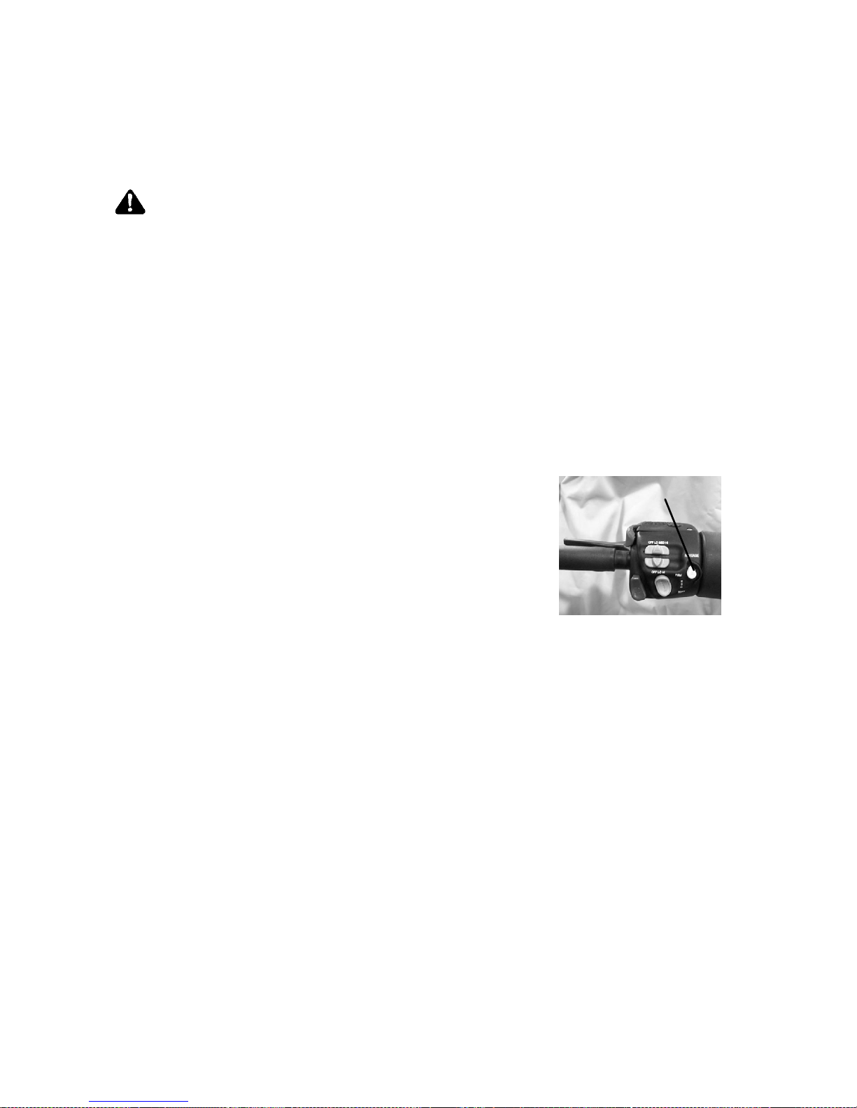
82
OPERATION
Electronic Reverse (PERC 4t)
Electronic reverse will activate only when the vehicle is stopped and
engine speed is below 2500 RPM. Maximum engine speed when
operating in reverse will be 6000 RPM.
WARNING
Improper reverse operation, even at low speeds, may cause loss
of control, resulting in serious injury or death. Damage will occur
to the gearcase or transmission if shifting is attempted when the
engine is operating above idle speed.
S Shift to or from reverse only when the snowmobile is stopped
and when engine speed is at idle.
S Look behind the snowmobile before and while backing.
S Avoid sharp turns.
S Apply throttle slowly.
Engaging Reverse
1. Stop the snowmobile and leave the
engine idling.
2. Make sure the area behind your
snowmobile is clear.
3. Push the yellow reverse button on the
left-hand control for one second, then
release.
NOTE: A reverse light on the instrument panel will indicate that the
snowmobile is in reverse.
4. Apply the throttle slowly to make sure the snowmobile is in
reverse.
NOTE: If the engine stops running, the snowmobile will be in forward
gear when it’s restarted.
Disengaging Reverse
1. Stop the snowmobile and leave the engine idling.
2. Push the yellow reverse button for one second and release. The
light on the instrument panel will shut off.
3. Apply the throttle slowly to make sure the snowmobile is in
forward.
L
Page 86

83
OPERATION
n Emergency Stopping
The following chart lists methods for stopping the snowmobile in the
event of an emergency. See page 80 for more information about the
engine stop switch and throttle safety switch.
SYSTEM WHAT IT DOES THROTTLE
CONDITION
Ignition Switch Interrupts ignition circuit All
Brake Slows jackshaft All
Engine Stop Switch Interrupts ignition circuit All
Throttle Safety Switch Interrupts ignition circuit All
Page 87

84
OPERATION
Daily Storage
At the end of each ride, park the
snowmobile on a level surface
and support it at the rear with an
appropriate track stand. The
track should be suspended
approximately 4″ (10 cm) off
the ground.
Remove the key and cover the
snowmobile.
Towing
WARNING
Objects towed with a rope have no braking power and can easily
collide with the rear of the snowmobile or other objects, resulting
in serious injury or death. DO NOT tow toboggans, sleds,
saucers, or any type of vehicle with a rope. Only a stiff metal
pole connecting the towed object and the tow hitch on the
snowmobile should be used. If passengers are to be towed on a
toboggan or sled, make sure the pole is at least four feet (1.2
meters) long to prevent any possibility of contact between the
snowmobile’s track and a person riding in the towed object.
Braking distances increase when towing loads. Slow down to
maintain control of the snowmobile.
If the snowmobile becomes inoperable and must be towed, and if it
isn’t possible to use a rigid tow bar, attach the tow rope to the ski
spindles (not to the ski loops) t o prevent damage to the steering
components. Remove the drive belt before towing, and have someone
ride on the towed snowmobile to operate the brake and steering when
necessary.
CAUTION
Towing a disabled snowmobile with the drive belt in place can
result in serious damage to the engine and drive system. Always
remove the drive belt from a disabled snowmobile before towing.
Page 88

85
MAINTENANCE
Emission Control Information
Any qualified repair shop or qualified person may maintain, replace, or
repair the emission control devices or systems on your snowmobile.
Emission Control Label
Your snowmobile is equipped at the time of sale with an emission
control information (ECI) label and a factory-installed emissions
information hangtag. These items are required by U.S . Environmental
Protection Agency regulations. The ECI label is permanently affixed to
either the right side of the tunnel or the engine recoil cover. The ECI
label should not be removed, even after you purchase the snowmobile.
You may remove the factory-installed emissions information hangtag,
which is intended solely for your use in m aking a purchasing decision.
Emission Control Maintenance Requirements
Your snowmobile is certified to operate on gasoline with a minimum
octane level of 87 (R+M)/2. The emission control system designation
per SAE J1930 is MF I. If your snowmobile is equipped with a check
engine light and it comes on, you must take your snowmobile to a
qualified dealer for diagnostic service. Specifications and adjustments
for engine tune-ups are located in the Service Manual, which is
available to your qualified service technician. Reverse (if equipped)
must not be engaged during engine tune-ups.
Page 89

86
MAINTENANCE
Emission Control Information
Owner’s Responsibilities
Please read the Snowmobile Engine Emissions Limited Warranty on
page 147, and read the maintenance section of your owner’s manual.
You are responsible for ensuring that the specified maintenance is
performed, including the emission--related maintenance outlined in
these sections of the manual.
You must inspect the air intake system on your snowmobile prior to
each use (including the airbox foam filter and hood foam filters) and
clean these components as necessary. Polaris considers the specified
maintenance for the spark plugs, oil changes, air i ntake system and
exhaust valves to be critical emission--related maintenance. The
specified maintenance for the fuel filter is recommended additional
emission--related maintenance. Polaris recommends that you contact
an authorized Polaris dealer to perform any service that may be
necessary.
Page 90

87
MAINTENANCE
Polaris Recommended Maintenance Program
To ensure many trouble-free miles of snowmobiling enjoyment, follow
recommended regular maintenance and perform service checks as
outlined in this manual. Record maintenance and service in the
Maintenance Log beginning on page 149.
The recommended maintenance schedule on your snowmobile calls for
service and maintenance inspections at 150 miles (240 km), 500 miles
(800 km) and 1500 miles (2400 km). These inspections should be
performed by a qualified service technician. For continued optimum
performance and component life, continue maintenance checks at 1500
mile (2400 km) intervals.
All necessary replacement parts and labor incurred, with the exception
of authorized warranty repairs, become the responsibility of the
registered owner. If, during the course of the warranty period, part
failures occur as a result of owner neglect in performing recommended
regular maintenance, the cost of repairs are the responsibility of the
owner.
Personal safety is critical when attempting to service or make
adjustments to your snowmobile. If you’re not familiar with safe
service or adjustment procedures and the use of tools, or if you don’t
feel comfortable performing these tasks yourself, contact an authorized
Polaris dealer for service.
NOTE: Polaris does not recommend tipping the snowmobile onto it’s
side for service. Any time the snowmobile is tipped onto it’s
left side, always check the oil level and clean the foam oil
breather element. See page 97.
CAUTION
Hot components can cause damage to plastic. Always make
sure the exhaust system and engine have cooled before tipping
the snowmobile on its side for service or inspection.
Tool Kit
A tool kit is included with each snowmobile for emergency use.
Always keep the tool kit with the snowmobile.
Page 91

88
MAINTENANCE
Periodic Maintenance Interval Table
D = Perform Service
" = Replace
DAILY
or
PRERIDE
INITIALLY
mi
(km)
YEARLY
or EVERY
mi
(km)
Item Pg Instructions
(see referenced pages)
150
(240)
500
(800)
1500
(2400)
Engine Stop Switch
71
Test for proper operation. Do not
D
Ignition Switch
71
ppp
operate ifswitchesfail, see your
dealer
f
or service.
D
Throttle Safety
Switch
80
dealerforservic
e
.
D
Taillight
71
Test for proper operation, replace
D
Brakelight
71
ppp,p
bulbs as needed
D
Headlight
71
D
Skags (Wear Bars) 127 Inspect for wear or damage, replace
when worn
D
Fluid Leaks
-- Inspect for fluid leaks
D
Parking Brake 68 Test for proper engagement and re-
lease, see your dealer for service
D
Brake Lever
67 Check lever travel and lever “feel”
D
Coolant
106
Inspect level, add as needed
D
Brake fluid
112 Inspect fluid level, add as needed
D CHANGE EVERY 2 YEARS
Hood Latches
66
Secure properly, replace if damaged
D
Seat Latches
65
Secure properly, replace if damaged
D
Rail Slide 124 Inspect for wear or damage, replace
when worn
D
Foam Oil Breather
Element
97 Check pre-ride, clean or replace
with each oil change. Clean after tipping 3 times onto left side.
D D D D
Front/Rear
Suspension and
Steering Fasteners
70 Inspect for missing or loose bolts
and fasteners, tighten or replace as
needed
WEEKLY / BEFORE LONG TRIPS
Front Limiter Strap
-- Inspect for wear, damage and missing or loose fasteners, replace as
needed
WEEKLY / BEFORE LONG TRIPS
Oil Lines
-- Inspect, replace if worn or damaged
D D D
Alternator Belt 104 Check tension and condition,
replace if worn or damaged
D D D
Page 92

89
MAINTENANCE
Periodic Maintenance Interval Table
D =Perform
" = Replace
DAILY
or
PRERIDE
INITIALLY
mi
(km)
YEARLY
or EVERY
mi
(km)
Item Pg Instructions
(see referenced pages)
150
(240)
500
(800)
1500
(2400)
Coolant Hoses
--
Inspect, replace if worn or damaged
D D D
Heat Exchangers
--
Inspect, replace if damaged
D D D
Throttle Lever 65
81
D D D
Fuel Lines
103 Inspect, replace if worn or damaged
D D D
Battery
Clean terminals, test voltage
D D D
Track Alignment
124
Verify alignment, adjust as needed
D D D
Track Tension
122
Verify tension, adjust as needed
D D D
Handlebars
--
Verify alignment, adjust as needed
D D D
Drive Chain
110
Verify tension, adjust as needed
EVERY
Rear Track Shock
(M-10)
-- Inspect covers and caps for wear or
damage, replace as needed
EVERY
Gearcase Oil 100 Check at 500 mi. (800 km), change
every 1000 mi. (1600 km)
D
EVERY
1000 (1600)
Rear Suspension 98 Lubricate pivot shafts
(more often in wet snow conditions)
D D
Bearings 131 Lubricate drive shaft and jackshaft
bearings
D D
Throttle Cable
98
Lubricate
D D
Clutches 116 Verify offset alignment, inspect for
wear, residue, loose bushings,
see your dealer for all service
D D
Drive Belt 117 Check tension and condition,
replace if worn or damaged
D D
Air Filter 104 Inspect for oil and dirt, replace as
needed
D D
Oil/Filter Change
94
Replace oil and filter
" "
Page 93

90
MAINTENANCE
Periodic Maintenance Interval Table
D =Perform
" = Replace
DAILY
or
PRERIDE
INITIALLY
mi
(km)
YEARLY
or EVERY
mi
(km)
Item Pg Instructions
(see referenced pages)
150
(240)
500
(800)
1500
(2400)
Engine Mounts
--
Inspect, replace if worn or damaged
D D
Spark Plugs 102 Inspect condition/gap, replace as
needed
D D
Exhaust System 105 Check muffler and pipe condition,
replace damaged or missing components, clean plastic surfaces
D D
Hoses -- Inspect for wear, damage and prop-
er routing, replace as needed
D D
Brake Pads/Disc
111 Inspect, replace if worn or damaged
D D
Fuel Vent Lines
103
Inspect, replace if worn or damaged
D D
Ski Toe 126 Verify alignment, see your dealer for
adjustments
D D
Cooling Fins/
Shroud
-- Inspect and clean
D D
Valve Lash -- See your dealer.
FS
Specifications
Intake: 0.08 - 0.15 mm
Exhaust: 0.15 - 0.20 mm
FST
Specifications
Intake: 0.08 - 0.15 mm
Exhaust: 0.18 - 0.23 mm
D EVERY
3000 (4800)
Cooling System 107 Bleed the cooling system, inspect
for leaks and proper circulation
EVERY
2000 (3200
Fuel Filter
103
Inspect, replace as needed
EVERY
2000 (3200)
Suspension Shock
Oil
--
Classic/Switchback only, see your
dealer for inspection
EVERY
2000 (3200)
Page 94

91
MAINTENANCE
Engine Oil
Always check and change the engine oil at the intervals outlined in the
Periodic Maintenance Ta ble beginning on page 88. Always change the
oil filter whenever changing oil. See page 133 for the part numbers of
Polaris products.
Performance Synthetic 4-Stroke (PS -4) Oil
Polaris recommends the use of Performance Synthetic 4-Stroke (PS-4)
0W50 oil for this engine. PS-4 has been specially formulated for use
in Polaris 4-cycle snowmobile engines. It’s a fully synthetic, high
performance, multi-viscosity oil designed to provide the ultimate in
lubrication performance and protection.
Oil may need to be changed more frequently if Polaris oil is not used.
Always use 0W50 oil. Follow the manufacturer’s recommendations for
ambient temperature operation.
CAUTION
Mixing brands or using a non-recommended oil may cause
serious engine damage. Always use the recommended oil.
Never substitute or mix oil brands.
Page 95

92
MAINTENANCE
Engine Oil
n
Oil Level Check
NOTE: Read the entire oil check procedure before checking the oil
level.
The oil level will rise as engine temperature increases. The oil level
will be lower when the engine is cold. To obtain a proper oil level
reading, the snowmobile must be on a level surface, and the engine
coolant temperature must be between 145 and 160 degrees F. (63-71
degrees C). Never add or remove oil if the engine coolant temperature
is not within the specified range.
NOTE: Always check the oil level before operating a snowmobile
that has tipped over.
CAUTION
Severe engine damage may occur if procedures for checking the
oil level are not followed precisely. Always check the oil with the
snowmobile positioned on a level surface. Always check the oil
when the coolant temperature is within the specified range.
1. Position the vehicle on a level surface.
2. If the engine is cold, start the engine and allow it to idle until the
engine coolant temperature reaches the specified range. Proceed to
step 4.
3. If the engine has been running, stop the engine and verify that
coolant temperature is within the specified range for performing
the oil check. Allow the engine to cool if necessary. When the
coolant is within the specified range, restart the engine and allow it
to idle for no more than 20 seconds to circulate the oil back into
the tank.
4. Turn the engine off.
NOTE: Check the oil level within
three minutes, before the
coolant temperature (and
oil level) begin to drop.
5. Remove the dipstick (L)
from the oil tank.
L
Page 96

93
MAINTENANCE
Engine Oil
n
Oil Level Check
6. Clean the dipstick with a clean shop towel and reinstall it, screwing
it in completely.
7. Remove the dipstick and view the oil level.
NOTE: The oil level reading will be accurate for only one to three
minutes after turning off the engine. If the oil check isn’t
completed within three minutes, reinstall the dipstick. Restart
the engine and allow it to idle for no more than 20 seconds to
circulate the oil back into the tank.
A. Fill mark for oil changes (at specified coolant temperature)
B. Safe operating range
8. Maintain the oil level in the safe operating range (B), between the
upper and lower marks on the dipstick. If the level is low, add the
recommended oil in small increments, about 2 ounces (60 ml), and
recheck the level. If the level is high, remove 2 ounces (60 ml) and
recheck the level.
CAUTION
Do not overfill the oil tank. Engine damage may occur. Always
add oil in small increments and recheck the level to avoid
overfilling.
9. Recheck the oil level if oil was added or removed, making sure the
coolant temperature is within the specified range. If necessary,
continue adding or removing oil until the level is in the safe
operating range.
B
A
Page 97

94
MAINTENANCE
Engine Oil
Oil Change
Always change the oil at the intervals outlined in the Periodic
Maintenance Table beginning on page 88. Clean the foam oil breather
element with each engine oil change. See page 97.
Always use the recommended oil. See page 91, or see your Polaris
dealer about oil change kits, which contain a new filter and the
recommended oil.
NOTE: A special jumper harness is required for changing the oil on
this vehicle. Please see your Polaris dealer to purchase the
harness, which will allow you to use the ignition key to turn
over the engine without starting it. You may also need an
assistant to help with the oil change.
1. Position the vehicle on a level surface.
2. Make sure the engine coolant temperature is between 145 and 160
degrees F. (63-71 degrees C). If necessary, start the engine and
allow it to idle until the coolant temperature is within the specified
range.
3. Turn the engine off.
CAUTION
Hot oil and a hot exhaust system and engine can cause serious
burns. Do not allow hot oil or hot components to contact skin.
4. Open the hood and remove the left side panel.
NOTE: Clamp orientation is critical to the proper operation of the
system. Be aware of clamp placement and orientation when
removing hose clamps. Always reinstall hose clamps in the
same location and position.
5. Remove the oil return hose from the oil tank. Have an assistant
place the end of the hose into a drain pan.
6. Disconnect the starter motor solenoid control switch harness.
7. Insert the female WHITE/RED plug into the male pin from the
starter motor solenoid.
8. Insert the BR OWN male pin of the jumper harness into the starter
solenoid’s female port.
Page 98

95
MAINTENANCE
Engine Oil
Oil Change
9. Open the handlebar cover . Locate the connector with the BROWN
and RED/WHITE wires. Connect the BROWN wire from the
jumper harness to the BROWN wire on the handlebar harness by
inserting the harness plug into the handlebar wiring harness
connector.
10. Open the fuse box and remove the 20A EFI fuse from the fuse
block.
11. R einstall the left side panel.
12. Have an assistant use the ignition key to turn over the engine.
Crank the engine for 15 seconds.
13. Wait 30 seconds to allow the starter motor to cool down.
14. Repeat steps 12 and 13 four more times for a total of five cycles.
15. Reconnect the oil return line to the oil tank. Tighten the hose
clamp securely, but do not over-tighten.
16. To prevent oil spillage, wait 3 to 5 minutes to allow any oil in the
oil filter cap to drain out before removing it. While waiting,
remove the foam oil breather element from the airbox. S ee page
97.
17. Inspect the foam element. Clean it with soap and water and let it
dry. Reinstall it, or install a new element if the existing element is
damaged or degraded and unable to absorb liquid.
18. Remove the oil filter cap, then remove the oil filter. Inspect the
o-ring and replace it if it’s worn or damaged.
19. Install a new filter, then reinstall the cap. Tighten the cap to 17 ft.
lbs. (23 Nm).
20. Remove the jumper from the starter motor wiring harness.
Reconnect the solenoid and the originally-installed harness.
Reinstall the 20A EFI F use.
21. Remove the dipstick from the oil tank. Add 2 quarts (1.9 liters) of
the recommended oil. Reinstall the dipstick.
Page 99
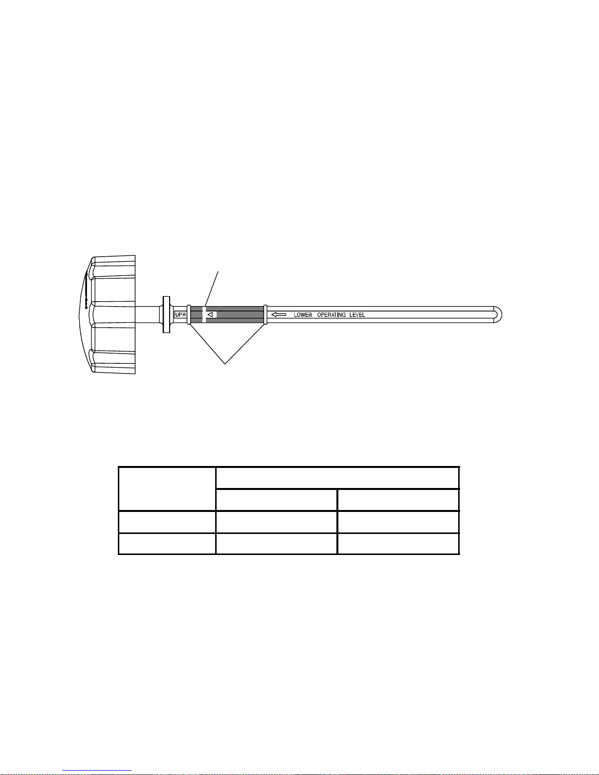
96
MAINTENANCE
Engine Oil
Oil Change
22. Make sure the engine coolant temperature is between 145 and 160
degrees F. (63-71 degrees C). If necessary, start the engine and
allow it to idle until the coolant temperature is within the specified
range.
23. Remove the dipstick from the oil tank. Clean the dipstick with a
clean shop towel and reinstall it, screwing it in completely.
24. Remove the dipstick and view the oil level.
A. Fill mark for oil changes (at specified coolant temperature)
B. Safe operating range
25. Add additional oil to bring the level to the oil change fill mark (A).
See the chart for approximate amounts to add at this step. DO
NOT OVERFILL.
MODEL OIL TO ADD AT STEP 25
Ounces Milliliters
FS 4to16 118to473
FST 24 to 32 710 to 946
NOTE: Check the oil level often during the fill procedure to avoid
overfilling. If the filling and checking procedure is not
completed within three minutes, reinstall the dipstick. Restart
the engine and allow it to idle for no more than 20 seconds to
circulate the oil back into the tank. Continue adding and
checking the oil until the level reaches the oil change fill
mark. Do not overfill.
26. Reinstall the dipstick.
B
A
Page 100

A
B
97
MAINTENANCE
Foam Oil Breather Element
The foam oil breather element absorbs small amounts of liquid to
protect sensors within the intake system from damage due to oil
ingestion. Clean or replace the breather element at each engine oil
change. Clean the element if the snowmobile has been tipped on its left
side three times, either during service or while riding, as oil may leak
into the element.
CAUTION
Operating the snowmobile with a clogged foam oil breather
element can result in severe engine damage. Always clean or
replace the element as recommended.
The foam oil breather element is located inside the airbox.
A. FS foam element
B. FST foam element
1. Open the hood.
2. Release the airbox cover
retaining clips and remove the
cover.
3. Remove the foam breather
element.
4. Wash the foam element in soapy
water, then rinse thoroughly and
let dry.
NOTE: If soap and water are not
readily available, remove as
much liquid as possible by
pressing the foam element
in paper towels or a similar
absorbent material.
5. Reinstall the dry foam element, or install a new foam element.
NOTE: Always replace a foam element that is brittle, cracked,
crumbling or otherwise damaged. For best performance,
routinely replace the foam element with every other engine
oil change.
6. Reinstall the airbox cover. Secure all retaining clips.
 Loading...