

Page 1
2004
2004
Frontier Classic
Frontier Classic
Frontier Touring
Frontier Touring
Owner's Manual
Owner's Manual
for Vehicle Maintenance
for Vehicle Maintenance
and Safety
and Safety
Page 2
Read, understand, and follow all of the instructions
and safety precautions in this manual and on all
product labels.
Failure to follow the safety precautions could result
in serious injury or death.
WARNING
The engine exhaust from this
product contains chemicals known
to cause cancer, birth defects or
other reproductive harm.
PROPOSITION 65
WARNING
Snowmobile engines discharge fuel
and exhaust, which contain chemicals
known to the State of California to
cause cancer and birth defects or other
reproductive harm, onto the snow on
which they operate. Keep this engine
properly tuned and avoid unnecessary
idling and spillage during fueling.
Page 3

1
What’s the hottest thing on snow?
Our new web site. And it’s designed just for YOU!
S Technical tips
S New product introductions
S Event schedules
S Parts and Service Manual information
S Exciting details about The Way Out
Check it out...
www.polarisindustries.com/owner
Page 4

2
Copyright 2003 Polaris Sales Inc. All information contained within this publication is
based on the latest product information at the time of publication. Due to constant
improvements in the design and quality of production components, some minor
discrepancies may result between the actual vehicle and the information presented in this
publication. Depictions and/or procedures in this publication are intended for reference
use only. No liability can be accepted for omissions or inaccuracies. Any reprinting or
reuse of the depictions and/or procedures contained within, whether whole or in part, is
expressly prohibited. Printed in U.S.A.
Page 5

3
WELCOME
Thank you for purchasing a Polaris vehicle, and welcome to our
world-wide family of Polaris owners. We proudly produce an exciting
line of utility and recreational products.
Polaris Recreational Vehicles
S Snowmobiles
S All-terrain vehicles (ATVs)
S Personal watercraft
S RANGER utility vehicles
S Victory motorcycles
Polaris Professional Series Workmobilest
S Utility Task Vehiclest (UTVs)
S Personal Task Vehiclest (PTVs)
S All-Surface Loaders (ASLs)
We believe Polaris sets a standard of excellence for all utility and
recreational vehicles manufactured in the world today. Many years of
experience have gone into the engineering, design, and development of
your Polaris vehicle, making it the finest machine we’ve ever
produced.
For safe and enjoyable operation of your vehicle, be sure to follow the
instructions and recommendations in this owner’s m anual. Your
manual contains instructions for minor maintenance, but information
about major repairs is outlined in the Polaris Service Manual and
should be performed only by a Factory Certified Master Service Dealer
(MSD) Technician.
Your Polaris dealer knows your vehicle best and is interested in your
total satisfaction. Be sure to return to your dealership for all of your
service needs during, and after, the warranty period.
We also take great pride in our Parts Apparel and Accessories (PAA)
products, available through our online store at www.purepolaris.com.
Have your accessories and clothing delivered right to your door!
Polaris, Polaris The Way Out, and Workmobiles are registered
trademarks of Polaris Industries Inc.
Page 6

4
TABLE OF CONTENTS
Introduction 5...............................
This section contains helpful information for owners and drivers and
illustrates the location of important identification numbers that should
be recorded in the owner’s manual.
Safety 8.....................................
This section describes safe vehicle operation and identifies warning
decals and their locations.
Features and Controls 28.....................
This section i dentifies the locations of your snowmobile’s controls and
features.
The Perfect Fit 33............................
This section explains how to tailor the suspension and other features
for an optimum riding experience.
Pre-Ride Inspections 53......................
This section explains procedures that must be performed before riding.
Operation 58.................................
This section explains proper engine break-in, operation of features and
general operating procedures.
Maintenance 71..............................
This section defines your role, and your dealer’s role, in your
snowmobile’s regular maintenance.
Specifications 116............................
Troubleshooting 118.........................
This section i s a quick reference guide to solving problems.
Polaris Products 124.........................
Warranty 125................................
Index 131....................................
Page 7

5
INTRODUCTION
Important Notes for Owners and Drivers
n After reading this manual, store it in the snowmobile for
convenient reference. It should remain with the snowmobile when
sold.
n The illustrations and photos used in this manual may be general
representations. Your model may differ.
n Follow the maintenance program outlined in this manual.
Preventive maintenance ensures that critical components of the
snowmobile are inspected by your dealer at specific mileage
intervals.
n You and your dealer must complete the registration form included
with your snowmobile and forward it to us. This completed form
is necessary to ensure warranty coverage.
n Protect and preserve your right to ride by joining your local trail
riding clubs.
Page 8

6
INTRODUCTION
Preservation of the Environment
Polaris is committed to supporting an environmental education
campaign. We encourage state and provincial governments across the
snowbelt to adopt rigorous safety training programs that encourage
protection of our environment, including wildlife and vegetation.
Snowmobile clubs and other organizations are working together to
protect our environment. Pl ease support their efforts and operate your
snowmobile with consideration for the protection and preservation of
our environment.
Respect your snowmobile;
respect your environment;
and you will earn
the respect of everyone.
Noise Level
One of the most publicized issues about snowmobiles is noise. The
Society of Automotive Engineers (SAE), the standard-setting body for
snowmobile development, recommends that snowmobiles conform to
prescribed sound levels.
Polaris snowmobiles are engineered to conform to these SAE
standards. Our muffler systems are designed to reduce noise levels and
must not be altered or removed. The sound of your snowmobile may
not be welcome to non-snowmobilers, so you have a responsibility to
operate your snowmobile with concern for others. We do our part by
manufacturing quieter machines; we ask your help to further reduce the
impact of noise by operating your snowmobile safely and responsibly.
Page 9

7
INTRODUCTION
Vehicle Identification Numbers
The tunnel vehicle identification number (VIN) and engine serial
number are important for m odel identification when registering your
snowmobile, when obtaining insurance, and when ordering
replacement parts. In the event your snowmobile is stolen, these
numbers are essential to its recovery and identification.
Remove the spare key and store it in a safe place. Your key can be
duplicated only by mating a Polaris key blank with one of your
existing keys. If both keys are lost, the ignition switch must be
replaced. See your Polaris dealer.
NOTE: Record your snowmobile’s ID numbers and key number in the
spaces provided.
Tunnel VIN (lower right side of the tunnel) :
Engine Serial Number (right side of engine cylinder head):
Vehicle Model Number:
Key Number:
Page 10
8
SAFETY
Operator Safety
The following signal words and symbols appear throughout this
manual and on your vehicle. Your safety is involved when these words
and symbols are used. Become familiar with their meanings before
reading the manual.
The safety alert symbol, on your vehicle or in this manual, alerts
you to the potential for personal injury.
The safety alert warning indicates a potential hazard that may result
in serious injury or death.
The safety alert caution indicates a potential hazard that may result
in minor personal injury or damage to the vehicle.
CAUTION
NOTE:
A note will alert you to important information or instructions.
A caution indicates a situation that may result in damage to the
vehicle.
CAUTION
WARNING
Page 11

9
SAFETY
Operator Safety
WARNING
Driving a snowmobile requires your full attention. DO NOT
drink alcohol or use drugs or medications before or while
driving. They will reduce your alertness and slow your reaction
time. In most states and provinces, it’s prohibited by law to
drive while intoxicated or under the influence of drugs.
Polaris produces high performance snowmobiles capable of
traveling at high speeds. Extra caution must be observed to
ensure operator safety. Make sure your snowmobile is in
excellent operating condition at all times. We strongly
recommend that the operator check major and vital safety
components before every ride.
All Polaris snowmobiles are designed and tested to provide
safe operation when used as directed. Failure of critical
machine components may result from operation with any
modifications, especially those that increase speed or power.
DO NOT MODIFY YOUR MACHINE. The snowmobile may
become aerodynamically unstable at speeds higher than those
for which it is designed. Loss of control may occur at higher
speeds. Modifications may also create a safety hazard and
lead to bodily injury.
The warranty on your entire machine is terminated if any
equipment has been added, or any modifications have been
made, to increase the speed or power of the snowmobile.
Page 12
10
SAFETY
Operator Safety
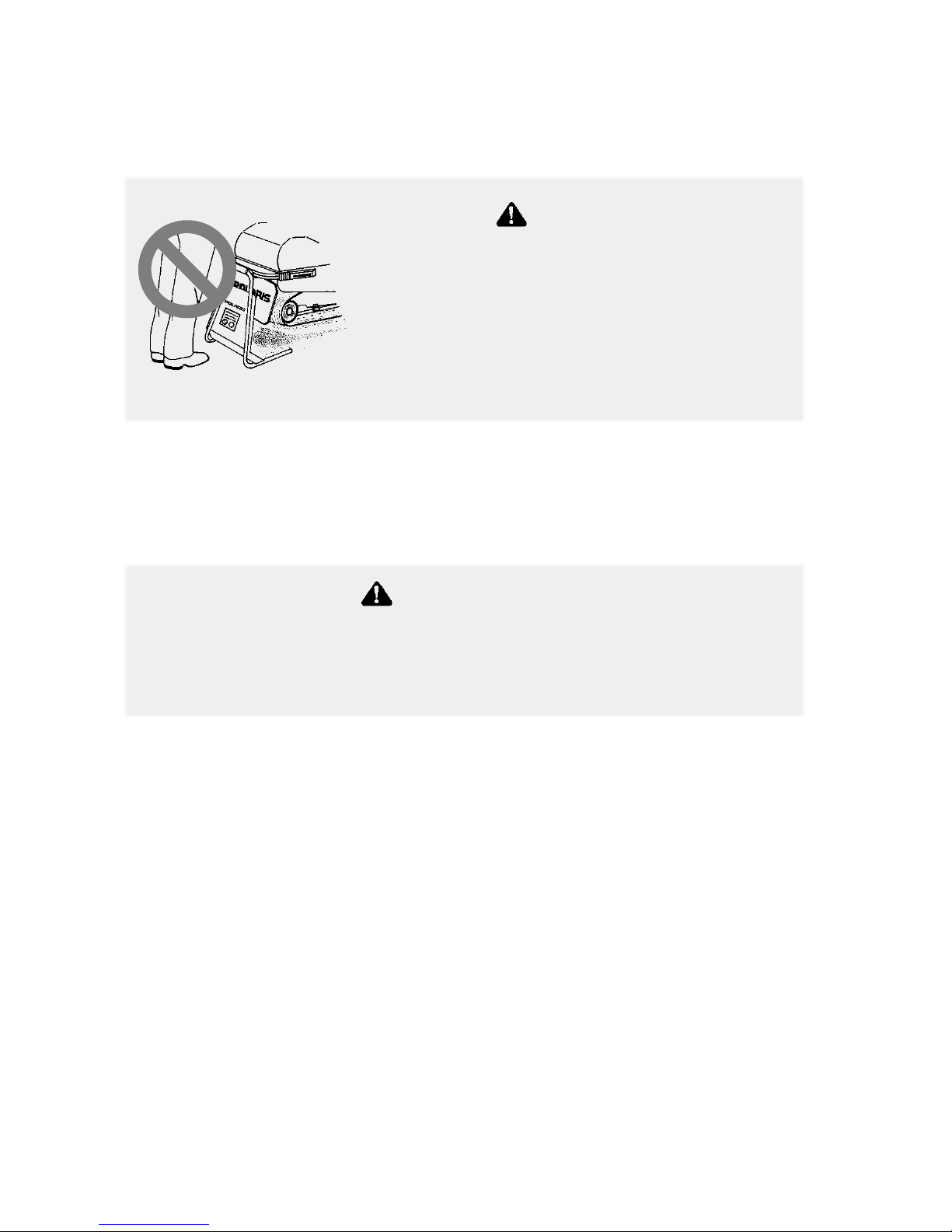
Stay Away From Moving Parts
Be alert when riding, and remain properly seated to stay clear of the
track. Your snowmobile is propelled by a revolving track that must be
partially exposed for proper operation. Serious injuries may result if
hands, feet, or clothing become entangled in the track.
Never attempt adjustments with the engine running. Turn off the
ignition, raise t he hood, make the adjustment, secure shields and
guards, secure the hood, and t hen restart the engine to check its
operation.
Never hold the snowmobile up or stand
behind it while warming up the track. A
loose track or flying debris could cause
serious personal injury or death.
We recommend having your dealer perform
track service and alignment procedures.
WARNING
If fingers or clothing contact the moving parts of an engine,
serious injury can result. Always stop the engine before
attempting adjustments.
WARNING
Page 13

11
SAFETY
Operator Safety
Riding Position
Operating a snowmobile requires skill and balance for proper control.
Rider positions may vary from person to person as each becomes more
skilled; but under m ost conditions, the proper position is to be seated
with feet on the running boards, and comfortably positioned for proper
throttle, brake, and steering control.
Survival Equipment
For your safety, always ride in a group of other snowmobilers. Always
tell someone where you’re going and how long you expect to be gone.
If it isn’t possible to ride with others, and you must travel into remote
areas, always carry survival equipment that’s appropriate to the
conditions you may encounter. Such equipment may include, but is
not limited to: extra clothing, a sleeping bag, a flashlight, food and
water, a signaling mirror, a means of building a fire, and a two-way
radio or cellular telephone.
Improper riding position may seriously reduce your ability to
control the machine and may result in serious injury or death.
Always be properly seated and in position to control your vehicle.
WARNING
Use of a backrest may hinder your weight shifting ability. This
could affect your ability to control this rider-active vehicle in
certain extreme driving situations.
WARNING
Page 14
12
SAFETY
Operator Safety
Cargo Overload
Too much weight on the rear of the machine may reduce your ability to
steer. Do not exceed carrier and rack weight limits, and do not allow a
passenger to sit on the seat back or the cargo carrier.
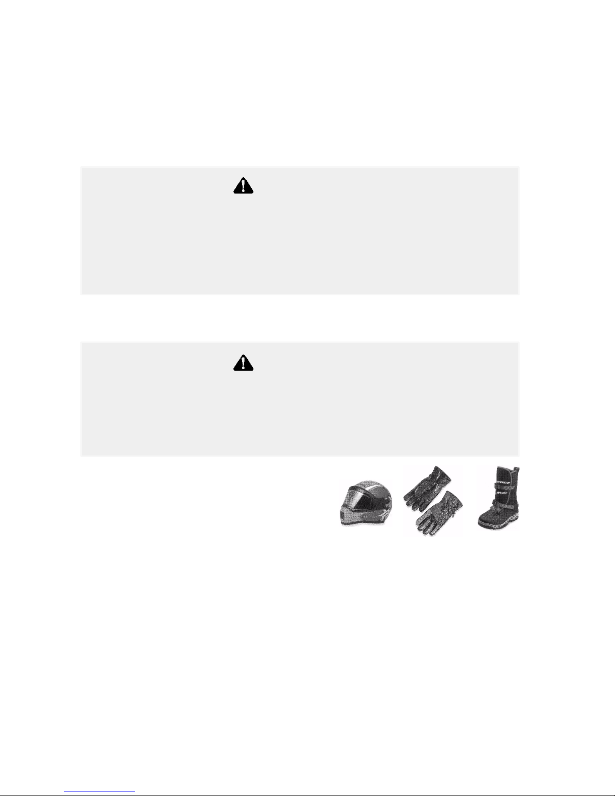
Riding Apparel
Be aware of the weather forecast,
especially the wind chill. A wind chill
table is provided on page 22 for your
reference. To better enjoy your ride, be
prepared, be warm and be comfortable.
Disabled Operators
Safe operation of this rider-active vehicle requires good judgement and
physical skills. Operators with cognitive or physical disabilities have
an increased risk of loss of control, which could result in serious injury
or death.
Control becomes more difficult with two people on board. More
space is required to make turns, and longer distances are needed
for stopping. Make sure the passenger remains seated behind the
driver, facing forward, with both feet placed firmly on the running
boards. Slow down and avoid “jumping” your snowmobile.
WARNING
Loose clothing or long scarves may easily become entangled in
moving parts and cause serious personal injury. Avoid wearing
loose clothing and long scarves while riding a snowmobile. Always
wear an approved helmet and eye protection.
WARNING
Page 15

13
SAFETY
Operator Safety
Excessive Speed
Observe all state and local laws governing snowmobile operation.
They’ve been established for your protection.
Always be alert and pay attention to the trail ahead. Multiplying speed
(MPH) by 1.5 will equal the approximate number of feet per second
your machine travels. If your speed is 40 MPH, your machine is
traveling about 60 feet per second. If you look back for only two
seconds, your machine will travel about 120 feet. If your speed is 60
MPH, your machine will travel about 180 feet.
Traveling at night requires extra caution. Check headlight and taillight
to ensure proper operation, and don’t “over drive” your headlight
beam. Always be able to bring your machine to a stop in the distance
illuminated by the headlight.
High speed driving, especially at night, could result in serious
personal injury or death. Obey local traffic laws pertaining to
snowmobile use and avoid using excessive speed.
WARNING
Page 16

14
SAFETY
Operator Safety
Driver Awareness
Slow down when traveling near poles,
posts, or other obstacles. Be especially
alert if you’re snowmobiling after dark.
Always be on the alert for wire fences.
Single strands are especially dangerous,
since there may be a great distance
between posts. Guy wires on utility poles
are also difficult to distinguish.
Make sure the way is clear before crossing
railroads and other roads and highways.
The noise of your machine will drown out
the sound of approaching vehicles. Look
ahead, behind, and to both sides before
turning or crossing railroad tracks or
highways. Steep embankments may also
hide your view. Always leave yourself a
way out.
Variances in snow depth and/or water
currents may result in uneven ice
thickness. Always check with local
residents or authorities for general information on conditions when
traveling on lakes and streams that are strange to you. Before riding
your machine on a frozen body of water, be sure the i ce is thick enough
to support the machine and its operator, as well as the force created by
a moving vehicle. You may drown if you and the snowmobile break
through the ice.
When teaching inexperienced operators to ride, set up a predetermined
course for practice. Make sure they know how to drive and control the
snowmobile before allowing them to make longer trips. Teach them
proper snowmobile courtesy, and enroll them in driver’s training and
safety courses sponsored by local or state organizations.
Page 17

15
SAFETY
Operator Safety
Ice and Snow Build-up
Before driving, manually turn the skis to the left and right to be sure
ice and snow are not interfering with full left and right steering. If
difficulty is encountered, check for ice and snow build-up that may be
obstructing t he steering linkage. Snow screens and bib kits are
available through your dealer to help reduce snow and ice build-up.
Driving o n Slippery Surfaces
Excessive shifting of operator body weight when turning on
hard-packed snow or ice may lead to loss of vehicle control and result
in serious injury or death. Slow down to maintain control under these
conditions.
It’s dangerous to drive on ice or other slippery surfaces. If it’ s
unavoidable, use extreme caution and operate at speeds no faster than a
walk. Never attempt an abrupt change of direction. The chance of
“spin-out” increases under these conditions.
Ice and snow build-up may interfere with the steering of your
machine, resulting in serious injury or death. Keep the underhood
area free of snow and ice.
WARNING
Driving on ice or hard-packed snow reduces steering and braking
control, which may result in serious injury or death. Slow down
and use caution.
WARNING
Page 18

16
SAFETY
Operator Safety
Driving in Hilly Terrain
Operating in hilly terrain requires extreme caution to maintain balance
and avoid roll-over. If climbing a hill is unavoidable, keep all your
weight low and forward.
If you must cross the face of a slope, keep your weight on the uphill
side of the machine to maintain proper balance and avoid possible
roll-over.
Slow down when reaching the crest of a hill. Be prepared to react to
obstacles, sharp drops, or other people or vehicles that may be on the
other side of the hill.
If you’re unable to continue up a hill, turn the machine downhill before
it loses momentum. If this isn’t possible, spin the track just enough to
dig in to prevent it from rolling back down the hill. Stop the engine
and set the parking brake (if equipped). Keeping away from the
downhill side of the machine, pull the rear of the snowmobile around
and point the front end and skis downhill. Remount the machine,
restart the engine, release the parking brake, and descend the hill
carefully.
Climbing a hill or crossing the face of a slope may result in loss
of balance and machine roll-over, causing serious injury or death.
Use caution and good judgement when driving in hilly terrain.
WARNING
Page 19

17
SAFETY
Operator Safety
Driving Downhill
When riding downhill, shift your weight to the rear of the machine and
reduce your speed to a minimum. Apply just enough throttle to keep
the clutch engaged, allowing the engine’s compression to help slow the
machine and keep it from rolling freely downhill.
Do Not Operate Engine With Clutch Guard Removed
The clutch guard is designed to protect the operator from metal parts if
the clutch should fail. Although the chance of failure is extremely
remote, don’t defeat the purpose of the guard by removing it. It’s
provided for your safety.
Do Not Operate Engine With Drive Belt Removed
Any servicing that requires operation without a belt must be performed
by your dealer. Operation of the engine with the belt removed may
result in personal injury or damage to the engine.
When driving on long downhill stretches, pump the brakes. Riding
the brakes may cause the brake system to overheat, which may
result in brake failure.
Excessive or repetitive use of the brakes for high speed stops will
also cause an overheated brake system. This condition may lead
to a sudden loss of brakes and/or fire and may result in serious
injury or death.
WARNING
Page 20

18
SAFETY
Operator Safety
Intake Silencer
Damage to the engine may occur if the intake silencer or filter are
removed.
Clutches
Do not attempt to service the clutches.
All clutch service must be performed by your dealer. The clutch is a
complex mechanism that rotates at high speeds. Each clutch is
dynamically balanced before installation. Any tampering may disrupt
this precision balancing and create an unstable condition.
Cold Weather Drive-Away
Whenever your snowmobile has been parked for a length of time,
especially overnight, always make sure the skis and track are loosened
from ice and snow before attempting to drive. Apply the throttle with
enough authority to put the machine into motion, but always operate
within safety limits.
Maneuverability
Control and maneuverability comes not only through the steering and
skis, maximum control is achieved by shifting of body weight.
Maneuverability will change for lighter operators or machines designed
to carry a load or a passenger.
Page 21

19
SAFETY
Operator Safety
Powder Snow Operation
Since snow provides the only lubrication for the power slide
suspension and cooling for the engine, adequate snow cover is a
requirement for operation of your machine. Driving in too little snow
will result in excessive wear and damage to the slide rail, track and/or
engine.
If the machine becomes stuck in snow, clear the running board area of
snow, then step down the snow in front of the machine so that when
the throttle is opened, the snowmobile will be able to climb up and
over. You m ay then mount the machine and continue riding.
Do not drive for prolonged periods on blacktop, gravel, or ice.
Doing so could cause irreversible track damage and lead to serious
personal injury.
WARNING
When operating on icy surfaces or hard-packed snow, avoid
overheating the slide rail and track. Lack of lubrication and
cooling will cause overheating of the slide rail and track, resulting
in premature wear and failure. If frequently operating in low
cooling conditions, see your dealer for an optional wheel kit that
will reduce the wear from overheating.
CAUTION
Page 22

20
SAFETY
Operator Safety
Your Polaris snowmobile is a well-engineered and well-constructed
recreational vehicle. Follow the recommended maintenance program
(beginning on page 71) to ensure that all critical components on the
snowmobile are thoroughly inspected by your dealer at specific
mileage intervals.
Rider Capacities
Some Polaris snowmobiles are designed for a single rider only.
Machines designed for two riders should never be operated with more
than two people on board. When traveling with a passenger, it’s the
driver’s responsibility to operate the machine safely.
Slow down! Control becomes more difficult with two people on board.
More space is required to make turns, and longer distances are
necessary for stopping.
Page 23

21
SAFETY
Operator Safety
Driving Responsibly
Every snowmobile handles differently, and even the most docile
conditions may become dangerous if operators drive improperly. If
you’re new to snowmobiling, acquaint yourself with the machine and
with what it will and won’t do under various conditions. Even
seasoned drivers should spend some time getting the feel for a machine
before attempting ambitious maneuvers.
S A snowmobile depends on the rider’s body position for proper bal-
ance in executing t urns, traversing hills, etc. Always start on a
smooth, level area to begin building your operating experience.
S Before allowing someone else use your snowmobile, know the ex-
tent of their operating skills. Check to see if they’ve taken a snowmobile safety course and have an operator’s certificate. For their
protection, as well as yours, make sure they take a snowmobile safety course. Everyone can benefit from the course.
S Don’t “jump” your snowmobile. Jumping may injure your back be-
cause of spinal compression. The seat and suspension of your snowmobile have been designed to provide protection under normal
riding conditions. Your snowmobile is not intended for this kind of
use.
S Be courteous to oncoming traffic by dimming your headlights and
reducing your speed. Your snowmobile is equipped with a high output headlamp system that may cause discomfort to operators of oncoming vehicles when on high beam.
S When traveling in a group of snowmobiles, don’t tailgate (follow too
closely). Allow ample stopping distances, and keep track of those
following you. Drive defensively to avoid accidents.
S Remove the key from the ignition when leaving the snowmobile un-
attended.
Page 24

22
SAFETY
Operator Safety
Windchill/Temperature Charts
The following charts will help you determine when t emperatures
become dangerous for riding.
WIND CHILL CHART (°F)
Estimated Wind Speed
Actual Thermometer Reading (°F)
p
in MPH
50 40 30 20 10 0 -10 -20 -30 -40 -50 -60
Equivalent Temperature (°F)
Calm 50 40 30 20 10 0 -10 -20 -30 -40 -50 -60
5 48 37 27 16 6 -5 -15 -26 -36 -47 -57 -68
10 40 28 16 4 -9 -21 -33 -46 -58 -70 -83 -95
15 36 22 9 -5 -18 -36 -45 -58 -72 -85 -99 -112
20 32 18 4 -10 -25 -39 -53 -67 -82 -96 -110 -124
25 30 16 0 -15 -29 -44 -59 -74 -88 -104 -118 -133
30 28 13 -2 -18 -33 -48 -63 -79 -94 -109 -125 -140
35 27 11 -4 -20 -35 -49 -67 -82 -98 -113 -129 -145
40 26 10 -6 -21 -37 -53 -69 -85 -100 -116 -132 -148
Wind Speeds Greater
Than 40 MPH Have
Li
t
tleAdde
d
Eff
ect
Little Danger
(For Properly
Clo
the
dPers
on)
Increasing
Danger
Great
Danger
LittleAddedEffectClothedPerson)
Danger From Freezing of Exposed Flesh
WIND CHILL CHART (°C)
Estimated Wind Speed
Actual Thermometer Reading (°C)
p
in KPH
5 0 -5 -10 -15 -20 -25 -30 -35 -40
Equivalent Temperature (°C)
0 5 0 -5 -10 -15 -20 -25 -30 -35 -40
10 1 -4 -11 -16 -22 -27 -33 -38 -45 -50
20 -4 -9 -17 -23 -29 -36 -42 -48 -54 -61
30 -7 -13 -21 -28 -35 -42 -48 -55 -63 -69
40 -9 -16 -24 -32 -39 -47 -53 -61 -69 -76
50 -11 -18 -26 -34 -41 -49 -57 -64 -73 -80
60 -12 -19 -27 -35 -43 -51 -59 -66 -75 -82
70 -13 -20 -28 -36 -44 -52 -60 -68 -76 -84
Wind Speeds Greater
Than 70 KPH Have Little
Little Danger
(For Properly
Increasing
Danger
Great
Danger
Added Effect
(py
Clothed Person)
Danger From Freezing of Exposed Flesh
Page 25

23
SAFETY
Safety Decals and Locations
Warning decals have been placed on the snowmobile for your
protection. Read and follow the instructions of the decals and other
warnings on the snowmobile carefully. If any of the decals depicted in
this manual differ from the decals on your snowmobile, always read
and follow the instructions of the decals on the snowmobile.
If any decal becomes illegible or comes off, contact your Polaris dealer
to purchase a replacement. Replacement safety decals are provided by
Polaris at no charge. The part number is printed on the decal.
Clutch Cover Warning
This warning decal is found under the hood on the clutch cover:
Do not operate engine with hood open.
Do not attempt adjustment with engine running.
Do not operate engine with this guard open.
Never run engine with drive belt removed.
Never service clutches yourself - see your dealer.
Air Box Warning
This warning decal is found under the hood on applicable models:
CAUTION
Do not operate above 40 mph with hood-to-airbox
foam removed or engine failure will result.
Pressure Cap Warning
This warning decal is found on the coolant bottle cover of liquid
cooled models:
WARNING
Do not open hot.
Test or replace when changing coolant.
Press down and turn to release cap.
13 PSI
Page 26
24
SAFETY
Safety Decals And Locations
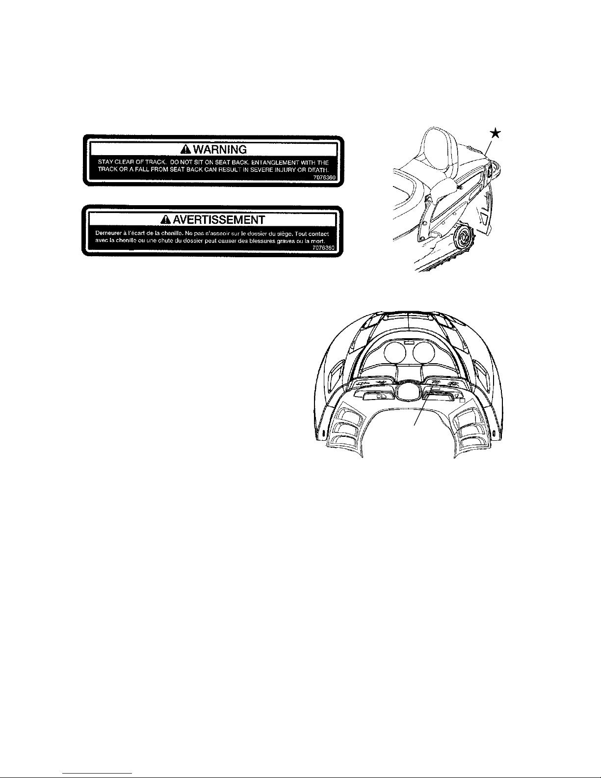
Track Warning
The track warning decal is located on the rear of the tunnel:
Passenger Warning
Some snowmobiles are designed
for the operator only, while others
are designed for the operator and
one passenger. The passenger
warning decal is located on the
right side of the console next to
the steering post. For more
information on operating
capacities, see page 20.
Decal found on 1-Up Models:
This vehicle is designed for operator only.
“NO PASSENGER”
Decal found on 2-Up Models:
This vehicle is designed for operator
and “ONE” passenger only.
+
Page 27
25
SAFETY
Safety Decals and Locations
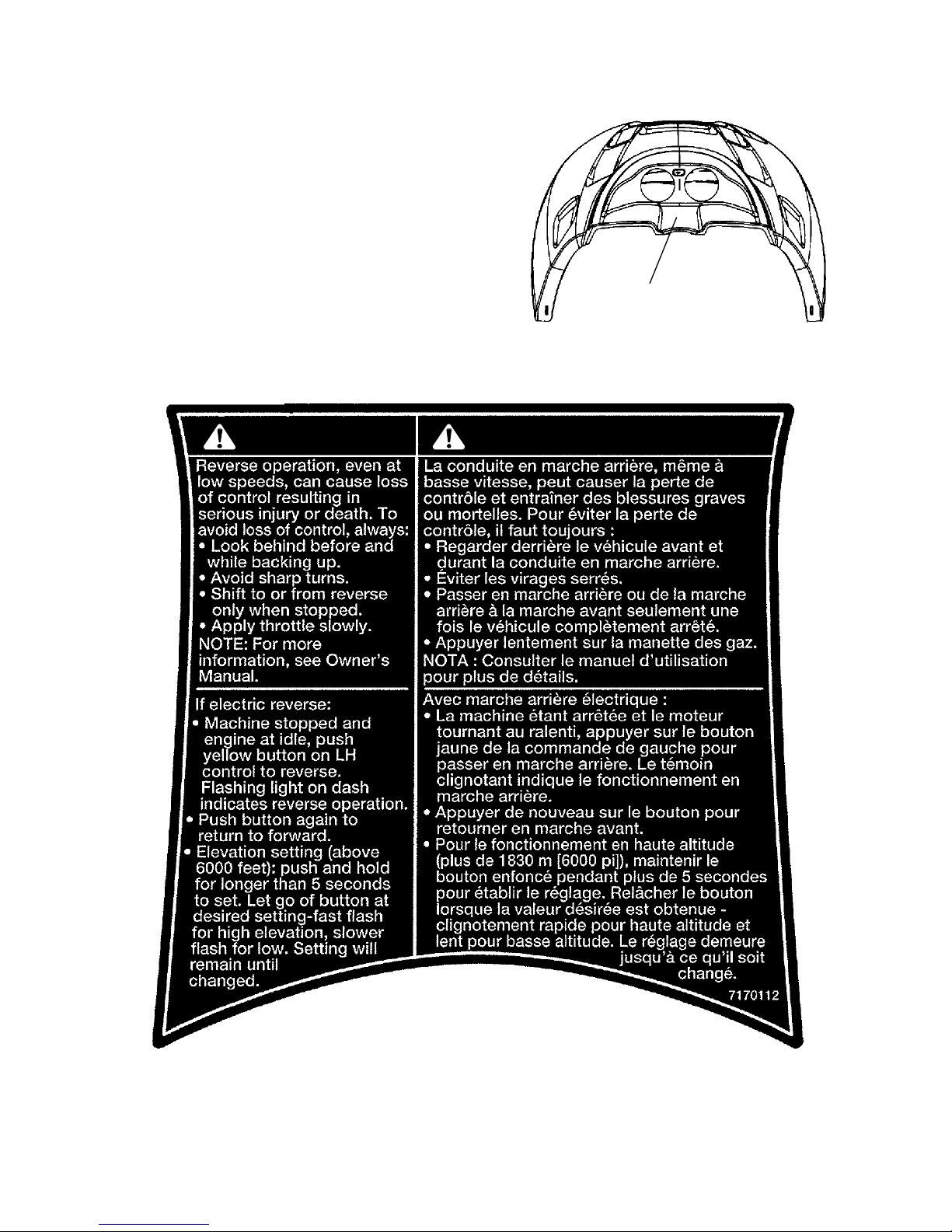
Electronic Reverse Warning
Polaris snowmobiles
equipped with electronic
reverse will have the
electronic reverse warning
decal.
+
WARNING AVERTISSEMENT
Page 28
26
SAFETY
Safety Decals and Locations
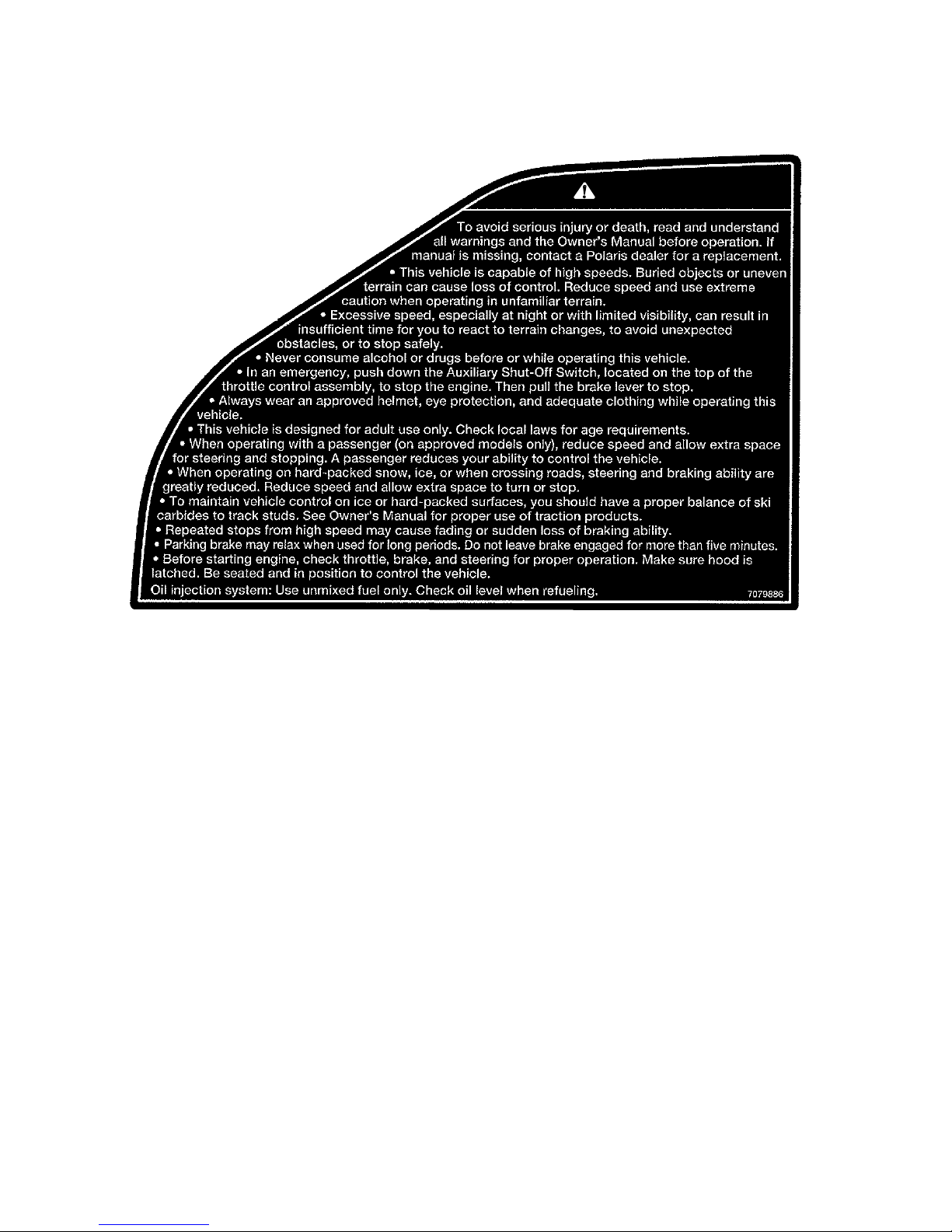
Operation Warning
Operation warning
decals are present on
the console of all
Polaris snowmobiles, in
both French and
English.
WARNING
Page 29

27
SAFETY
Safety Decals and Locations
Operation Warning
AVERTISSEMENT
Page 30
28
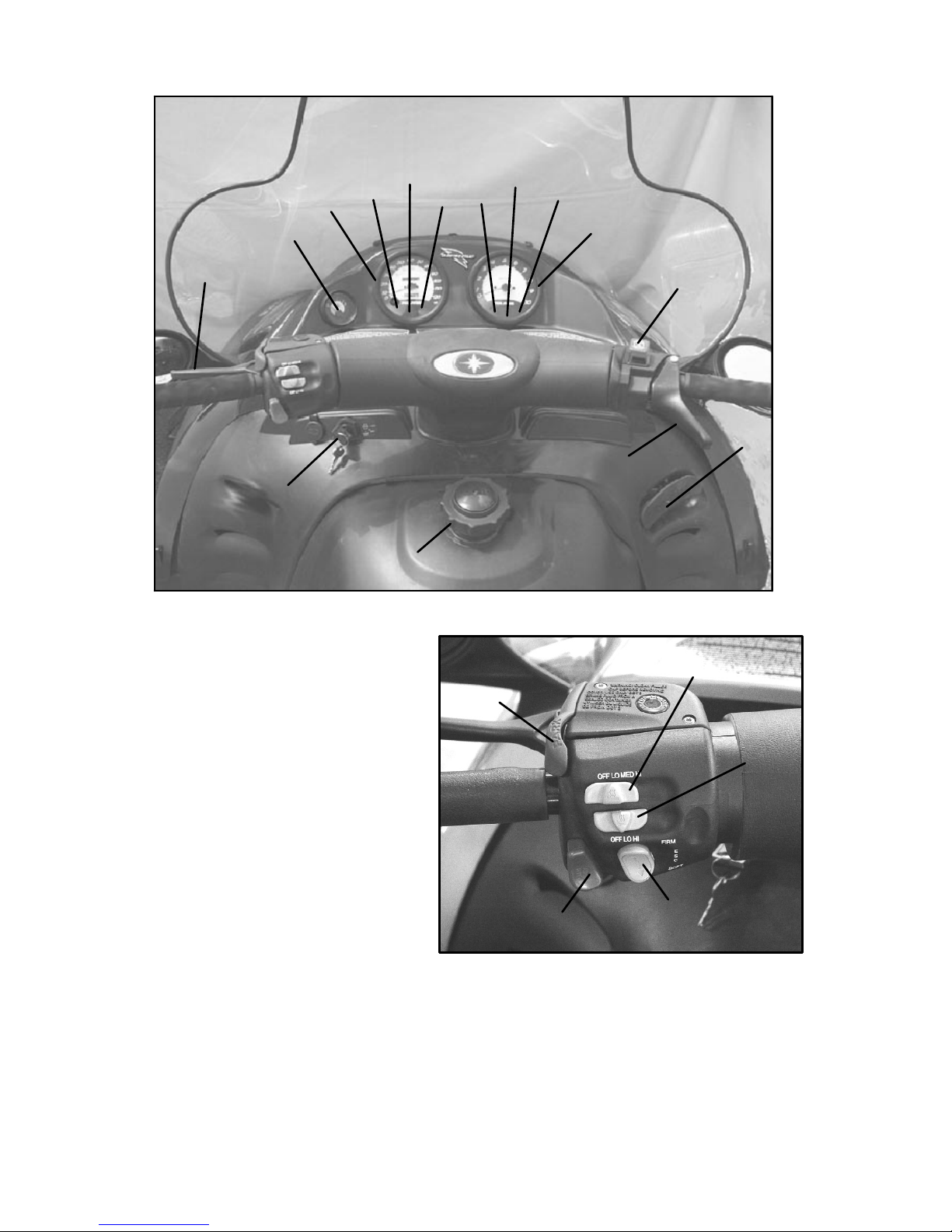
FEATURES AND CONTROLS
1. Fuel Filler Cap
2. Ignition Switch
3. Brake Lever
4. Electronic Fuel Gauge
5. Speedometer
6. Headlight High Beam Light
7. Low Oil Pressure Light
8. Brake Light
9. Check Engine Light
10. Reverse Indicator Light
11. Temperature Light
12. Tachometer
13. Engine Stop Switch
14. Throttle Control
15. Reverse Lever
16. Headlight Dimmer S witch
17. Park Brake Lock
18. Handlebar Grip Warmer Switch
19. Thumbwarmer Switch
20. Shock Adjust Switch
1
13
14
2
3
5
12
4
9
10
11
7
8
6
15
16
17
18
19
20
Page 31

29
FEATURES AND CONTROLS
Touring Model Shown
1. Hood
2. Headlight
3. Windshield
4. Handlebar
5. Seat
6. Passenger Seat (Touring)
7. Cargo Box (Touring)
8. Taillights
9. Snow Flap
10. Suspension
11. Track
12. Trailing Arm
13. Block Heater (under hood)
14. Nosepan
15. Front Bumper
16. Skis
1
2
3
4
5
8
11
10
14
12
16
15
7
9
13
6
Page 32

30
FEATURES AND CONTROLS
Malfunction Indicator Lamp (MIL)
The Frontier is equipped with a
malfunction indicator lamp (CHECK
ENGINE light) to assist your Polaris dealer
in diagnosing problems. The MIL codes
are for reference only. Full diagnostics
must be performed by a Polaris dealer
trained to service EFI systems.
When enabled, the CHECK ENGINE light
will blink in numerical sequences to
indicate the type of failure. For example: two blinks, pause, one blink
is the sequence for code 21. To enable the blink codes, put a 30 amp
automotive fuse in the ACS bypass three times within 2 1/2 seconds,
leaving it in the third time. NOTE: Disconnect the negative battery
lead for 10 seconds to clear the code.
MIL Diagnostic Code Summary
CODE MIL Description
21 Yes Lost synchronization
Synchronization of crankshaft position lost
22 Yes Throttle position sensor circuit error
Sensor signal is shorted to ground or at battery potential
23 Yes RAM error
Hardware failure or serial EEPROM not initialized or failure
24 Yes Speed circuit / sensor error
Crankshaft position sensor failure (if MIL stays on when cranking
there is no speed sensor input)
31 Yes System too lean
Lambda sensor shorted to ground or battery voltage
32 Yes 02 Sensor circuit error
Short to battery or no activity detected
33 No System too rich
Short term adaption at upper or lower limit.
34 No Maximum adaption limit reached
Long-term adaption at upper or lower limit
42 Yes Temperature sensor circuit error
Sensor short to ground/battery voltage/implausible signal
61 NA End of sequence message
If the ACS 30 AMP bypass fuse is left in, electrical drainage will
occur. To avoid electrical drainage, always remove the fuse from the
ACS bypass AFTER the End of Sequence message (61) appears.
CAUTION
Page 33

31
FEATURES AND CONTROLS
Check Engine Light
Your EFI system has an Electronic Control Unit (ECU), which is
pre-coded for any potential problems your EFI system will have. If a
problem with your EF I system occurs, a code is triggered and the
CHECK ENGINE light will come on. If the light comes on, take your
Frontier to a qualified Polaris dealer for diagnostic service.
Low Oil Pressure Light
A low oil pressure indicator light will alert you to a low oil condition.
When the low oil pressure indicator light is on, visually check the oil
level on the dipstick. If the oil level is below the SAFE mark,
continued operation will cause serious engine damage. Add the
recommended oil before further operation of the snowmobile. See
page 124 for the part numbers of Polaris products.
CAUTION
Operating the snowmobile without proper engine lubrication can
result in serious engine damage. Always check the oil level on the
dipstick when the low oil pressure light illuminates. Add the
recommended oil to maintain the oil level between the SAFE and
ADD marks on the dipstick.
CAUTION
Mixing brands or using a non-recommended oil may cause serious
engine damage. We recommend the use of Polaris Premium 4
Synthetic 0W-40 engine oil for your snowmobile. Never mix brands.
Page 34

32
FEATURES AND CONTROLS
Block Heater
To improve cold-weather starting, a block heater has been installed on
the engine of your snowmobile. When connected to a 110V electrical
outlet, the block heater warms the engine, making it easier to start in
subzero temperatures. We recommend the use of this block heater
whenever temperatures drop below -13° F. (-25° C.).
Open the hood to access the block heater plug-in (see page 29 for
location). Plug the cord into a 110 V outlet when the snowmobile will
be parked in subzero temperatures overnight or for more than a few
hours. Unplug the cord and return it to its storage area before starting
and operating the snowmobile.
Driving the snowmobile before unplugging the block heater could
result in damage to the heater and other components. Always
unplug the block heater before operating the snowmobile.
CAUTION
Page 35

33
THE PERFECT FIT
Front Suspension Adjustments
Break in the suspension for approximately 150 miles (240 km) and
re-grease all suspension parts before making any fine-tuning
adjustments.
Settings will vary from rider to rider, depending on rider weight,
vehicle speed, riding style, and trail conditions. We recommend
starting with factory settings and then customizing each adjustment
individually to suit rider preference. The machine should be
methodically tested, one change at a time, under the same conditions
(trail and snow conditions, vehicle speed, riding position, etc.) after
each adjustment until the best ride is achieved.
Independent Front Suspension (IFS)
The IFS is made up of the skis (1),
front shocks and springs (2), and the
components t hat connect these parts
to both the steering, such as the tie
rods (3), and to the machine itself,
such as the trailing arms (4).
Front suspension adjustments
include shocks, springs, toe,
and camber.
NOTE: Although the front
suspension on your machine
may not look exactly like the
illustration, it will have the
same parts and functions as
those illustrated.
IFS Adjustment Options
S Front shock spring preload
S Optional springs
S Toe (ski alignment) (see page 107)
S Camber (see your dealer)
1
2
3
4
Page 36

34
THE PERFECT FIT
Front Suspension Adjustments
For the best ride, the suspension should be adjusted to use the full
travel of the shocks with occasional light bottoming. To determine if
your machine is using full travel, push the jounce bumper down on the
shock rod until it contacts the body and test ride the machine. The
bumper will move up on the rod in relation to the amount of travel that
was used during the ride. If the travel is full, the bumper will be seated
at the top of the rod.
Shock Absorber Components
1. Retainer
2. Shock Rod
3. Jounce Bumper
4. Body
5. Threaded Spring Preload Adjuster Nut
Always verify ski alignment before making adjustments to the IFS.
See page 107 to check alignment. If the skis are misaligned, see
your dealer, as the camber adjustment may also be affected.
WARNING
1
2
3
4
5
Page 37

35
THE PERFECT FIT
Front Suspension Adjustments
Adjusting Front Shock Spring Preload
Increasing spring preload will increase
ski-to-ground pressure. Decreasing spring
preload will decrease s ki-to-ground
pressure. When adjusting, be sure the
springs on both the left and right sides of
the machine are at the same adjustment.
To increase front shock spring preload,
grasp the spring and turn it to the right.
Turn it to the left to decrease preload.
Illustration B indicates high preload and
illustration C indicates low preload.
Increasing the spring preload too much may adversely affect the
handling of the snowmobile and the performance of the suspension.
Never exceed one inch of preload beyond the factory settings, and
ensure that both sides are adjusted the same. When decreasing preload,
make sure at least two turns of preload are holding the spring between
the retainer on top of the shock and the threaded spring preload
adjuster nut on the shock body.
NOTE: Some models do not have shocks with thread adjustable
spring preload. See your dealer for more information.
Front Springs
For models without externally adjustable or revalvable shocks, the
front springs can be changed if spring preload alone isn’t sufficient and
further adjustment is desired t o control suspension stiffness. S ee your
Polaris dealer for more information.
CB
Always leave one thread showing above the adjuster nut.
On models equipped with a plastic adjuster nut, if the nut is
unscrewed from the threaded body, the nut will break.
CAUTION
Page 38

36
THE PERFECT FIT
Rear Suspension Adjustments
Rider weight, riding style, trail conditions, and vehicle speed all affect
suspension action.
Each rear suspension can be adjusted to suit rider preference and
deliver excellent performance for a given set of conditions. However,
all suspension designs and adjustments involve a compromise, or
trade-off. For example, a suspension set up for snow-cross racing
would provide a very stiff ride on the trail. A suspension set up for
trail riding would bottom out harshly on a snow-cross course.
A decal outlining rear suspension setup options is located either under
the hood or on the clutch cover. It provides a guideline for initial
suspension setup. Additional adjustments can be made from this point.
Make adjustments to one area at a time so you can evaluate the change.
For further assistance, see your dealer.
Suspension Performance Tips
S Rider weight usually determines the position at which the spring pre-
load should be set. However, this may vary with riding style. With
a little experimentation, each rider can find a preferred setup. These
adjustments are easy t o make, involve very little time or effort, and
greatly affect the ride.
S In deep snow, a new Hi-fax will offer improved performance over
worn Hi-fax. It can also improve top speed.
S When riding on ice or hard-packed snow, adding a set of bogie
wheels to the rail may enhance the machine’s performance. Bogie
wheel kits are available from your dealer.
S Polaris offers track kits for improved flotation in deep snow. See
your dealer for assistance.
NOTE: Keep the suspension pivot points lubricated. This will reduce
moisture and rust build-up and ensure proper function of the
suspension components. Grease rear suspension pivots before
adjusting the rear suspension. Refer to Suspension Lubrication
beginning on page 76.
Page 39

37
THE PERFECT FIT
FAST M-10 Rear Suspension Adjustments
The M-10 suspension has been designed to be very sensitive to rider
weight. Changes in rider weight of 25 lbs. or more might require
appropriate changes in settings. The following information has been
compiled to assist you in tuning your M-10 suspension to its maximum
potential and achieve the best possible ride. Please take the time to
read and understand all the possible adjustments available with the
M-10 suspension.
Static Sag and Ride Height Settings
Static sag describes the difference in height of the rear bumper from the
suspension’s fully extended position to its loaded height, with the rider
seated on the snowmobile.
A good initial starting point is four inches of sag, measured at the rear
bumper. Too much sag will result in bottoming, and too little sag will
result in reduced rider comfort.
Sag travel is used to control ride quality and rebound travel. On the
M-10 suspension, sag is controlled by two settings, the full range
adjuster (FRA) position and the rear spring preload.
1. To check sag, raise the rear bumper until the suspension is fully
extended (the rear shock will not extend any further). Measure the
distance from the ground to the bottom of the bumper (dimension
X) as shown in the illustration. Record the m easurement.
2. Have the rider sit on the snowmobile and bounce up and down on
the seat a few times t o set in the suspension. While the rider
remains seated, measure the distance from the ground to the top of
the bumper (dimension Y) and record it.
3. Subtract Y from X and you will have the SAG setting (X - Y = sag
setting. Example: 21 - 17 = 4). The correct amount of SAG for
the M-10 rear suspension is 3-5 inches.
If the measured sag is incorrect, adjust the FRA position and rear
spring preload.
X
Y
Unloaded Loaded
Page 40

38
THE PERFECT FIT
FAST M-10 Rear Suspension Adjustments
Static Sag and Ride Height Settings
FRA Position
The FRA setting is the primary rear suspension adjustment. It will have
the MOST effect on the rear suspension performance. To adjust the
FRA:
1. Refer to the initial setup reference chart (located under the hood of
your snowmobile and on page 43) to determine the desired FRA
position.
2. To adjust, loosen the hex bolts (A) attaching the rear lower shock
cross shaft to the rail beam.
3. Using a 9/16” wrench, loosen the jam nuts (B) on the preload
bolts.
4. Adjust the preload bolts (C) to the desired FRA position.
5. Tighten the jam nuts. NOTE: Make sure the preload bolt contacts
the slide block before tightening the jam nut.
6. Tighten the hex bolts and torque to 35 ft. lbs. (47 Nm).
NOTE: If the M-10 suspension is new, it will take from 25 to 200
miles to properly break in the springs and shocks, at which time the
suspension will be softer and may require FRA readjustment.
A
B
C
Page 41

39
THE PERFECT FIT
FAST M-10 Rear Suspension Adjustments
Static Sag and Ride Height Settings
Rear Spring Preload
The top section of the crossover tube (the tube at the top of the rear
shock) has a threaded collar on it. The rear spring has a lock tab that
fits into the collar to allow easy spring preload adjustment. Refer to
the initial setup chart on page 43.
1. To increase preload, use
the tool kit spanner wrench
to rotate the crossover
toward the left side of the
snowmobile (clockwise
when viewed from below).
Rotate toward the right
side to decrease preload
(counter-clockwise when
viewed from below). Be
sure the aluminum locknut
and adjuster collar are
locked against each other
before starting the
adjustment.
2. While adjusting, keep in
mind that spring preload is a
fine tuning adjustment. Coarse
adjustments should be made using the FRA.
NOTE: Preload is set “softest” when the preload (dimension B in illustration and setup chart) is equal to zero. Adjusting spring preload
beyond this could cause damage to the threads.
B
C
Page 42

40
THE PERFECT FIT
FAST M-10 Rear Suspension Adjustments
More M-10 Suspension Ride and Performance Settings
Overload Spring
The overload spring is located inside the m ain rear spring. Contact is
made with this spring only when the crossover tube comes in contact
with it toward the end of the travel, which reduces bottoming of the
rear suspension. The correct setting of the crossover tube length
enables the M-10 suspension to deliver superior performance in
“bottoming” situations. This adjustment has no effect on spring
pre-load or general ride characteristics of the M-10 rear suspension, it
affects only bottoming resistance. To adjust the crossover tube length
(dimension C in illustration and setup chart):
1. Use the spanner wrenches located in the tool kit to unlock the
upper lock nut from the adjuster collar.
2. Turn the adjuster collar to the appropriate or desired dimension for
the rider’s weight (refer to the initial setup reference chart located
under the hood of your snowmobile and on page 43). Using the
spanner wrenches, tighten the upper lock nut firmly against the
adjuster collar.
Optional Springs
Optional springs have been designed to allow adaptation of the M-10
suspension to your specific needs. The 140 lbs./in. optional front arm
spring would be used when very light load conditions exist, such as
operation on very smooth trails, in deep powder or by very light riders.
The 300 lbs./in. rear arm spring option would be used when high load
conditions exist, such as operation by heavy riders on rough trails or
very aggressive riding. The available springs for M-10 suspension are
listed below.
Location Spring Rate Polaris PN
Front Arm Standard
Front Arm Soft
Front Arm Firm
160 lbs./in.
140 lbs./in.
180 lbs./in.
7041671-216
7041677-067
7041672-067
Rear Arm Standard
Rear Arm Soft
Rear Arm Firm
210/278 lbs./in.
135/240 lbs./in.
300 lbs./in.
7041935-216
7042010-216
7042011-067
Overload 1000 lbs./in. 7041936-067
Page 43

41
THE PERFECT FIT
FAST M-10 Rear Suspension Adjustments
Other Ride and Performance Settings
Ski Pressure
Your M-10 rear suspension ski pressure is set at the factory to deliver
the optimum balance between ride and handling. If a rider prefers more
ski pressure for improved steering performance, adjustments can be
made to the front limiter strap and front arm mount.
1. To set the limiter,
determine if the rider
prefers comfort or
control. Lean toward the
#4 setting for comfort
and toward the #3
setting for aggressive
riding.
2. For full hole
adjustments, remove the
5/16” nut and flat
washers from the lower
attachments of the limiter straps and relocate the straps to the
desired position (i.e. move from position 4 to 3). Replace the nut
and washer tighten securely.
3. For half-hole increments (such as 3/4), the limiter straps have slots
at the upper pinch bolt. These slots allow the bolts to be loosened
(rather than removed) for half-step adjustments. It is now easy to
change to half-step hole positions (re-tighten the pinch bolts if
loosened).
4. There are also two front
arm mounting holes in the
slide rail that can adjust
ski pressure. The lower
hole (A) increases ski
pressure while the upper
hole (B) decreases ski
pressure.
NOTE: B y design, the BIASED COUPLE design of the M-10
suspension displaces the rear arm as the front arm is compressed. This
means t hat when you raise the front limiter strap, at some point you
will collapse the rear suspension arm, which will affect SAG height
and reduce rear suspension travel.
4
3
2
1
3
4
2
A
B
Page 44

42
THE PERFECT FIT
FAST M-10 Rear Suspension Adjustments
Other Ride and Performance Settings
Track Tension
Track adjustment is critical for proper
handling. Always maintain correct
tension and alignment. Tension
adjustments should be made only after
the track is warmed up and limber.
1. Turn the machine off.
2. Lift the rear of the machine and
safely support it off the ground.
3. Place the recommended weight
or downward pressure on the
track at the specified distance
(see chart below) ahead of the
center of the rear idler wheel. NOTE: Measure at the point where
the weight is hanging.
4. Check for specified slack between the wear surface of the track clip
and the plastic Hi-fax (C).
If the track needs adjustment:
5. Loosen the rear idler shaft bolts (D) and locknuts (A).
6. Tighten or loosen the track adjusting screws (B) as necessary to
provide equal adjustment on both sides of the track.
7. Tighten the locknuts (A). Then tighten the idler shaft bolts (D) to
35 ft. lbs. (47 Nm).
NOTE: Always inspect track alignment after track tension adjustment.
Track alignment affects track tension. Misalignment will cause
excessive wear to the track and slide rail. Excessive Hi-Fax wear will
appear on units with track tension set too tight. Refer to the Master
Repair Manual for track alignment procedure.
Track Tension Data
Suspension Weight Measurement
Location
Slack
Measurement
Edge Touring 10 lbs. (4.54 kg) 16″ ahead of rear
idler shaft
3/4 - 1″
(1.9 - 2.5 cm)
M-10 10 lbs. (4.54 kg) 16″ ahead of rear
idler shaft
7/8″ -11/8″
(2.2 - 2.9 cm)
M-10 ACE 10 lbs. (4.54 kg) 16″ ahead of rear
idler shaft
7/8″ -11/8″
(2.2 - 2.9 cm)
C
D
Track
Hi-fax
B
A
Page 45

43
THE PERFECT FIT
FAST M-10 Rear Suspension Adjustments
Initial M-10 Suspension Setup Chart
NOTE: These positions are only preliminary. Experimentation should
follow initial setup to obtain optimum results. Refer to the suspension
troubleshooting decal for additional setup tips.
INITIAL SETUP REFERENCE CHART
This chart is a guideline to be used for initial suspension setups.
Your setup may vary based on your desired riding style.
FRA Position DimensionBDimension
C
Rider
SOFT FIRM Rear
Crossover
Limiter/Ski
Weight with
full ridin
g
Spring
Preload
Tube
Leng
th
Pressure
Settin
g
s
fullridin
g
gear
PreloadLengthSettings
Settings
In / mm In / mm Light / Firm
100 lbs. 1 11/4 005 5/8 143 4/4 3/3
125 lbs. 1 11/2 005 13/16 148 4/4 3/3
150 lbs. 1 11/2 5/16 8 5 13/16 148 4/4 3/3
175 lbs. 11/2 2 5/16 8 5 13/16 148 4/4 3/3
200 lbs. 2 21/2 5/16 8 5 3/4 146 4/4 3/3
225 lbs. 21/2 3 5/16 8 5 5/8 143 4/4 3/3
250 lbs. 3 31/2 5/16 8 5 9/16 141 4/4 3/3
275 lbs. 3 31/2 1/2 13 5 7/16 138 4/4 3/3
300 lbs. 3 31/2 1/2 13 5 3/16 132 4/4 3/3
325 lbs.* 3 31/2 5/8 16 5 3/16 132 4/4 3/3
350 lbs.* 31/2 4 5/8 16 5 3/16 132 4/4 3/3
375 lbs.* 4 5 7/8 22 5 3/16 132 4/4 3/3
*Might prefer optional spring (rear track) Refer to the list on page 40.
Page 46

44
THE PERFECT FIT
FAST M-10 ACE Suspension Adjustments
The FAS T M-10 ACE (Adjustable Control Electronics) is a new
feature available for some FAST M-10 rear suspensions. It enables a
rider to easily adjust the suspension for weight and riding style.
The M-10 ACE is an electronically controlled module that replaces the
standard M-10 FRA. The ACE changes the rear shock motion ratio by
moving the lower shock pivot point a total of 1 1/4 inches, the same
amount of adjustment as the standard FRA. A gauge on the console
displays the current position of the shock, from soft to firm or
somewhere in between.
M-10 ACE Settings
A switch labeled “ESC” on the left-hand control assembly is used to
adjust the position of the ACE module. The following instructions
describe all the features programmed into the ACE module.
1. By pressing the left hand control switch up (firm) or down (soft)
one time, the lower pivot moves .14 inch, giving the operator a
total of nine distinct positions. The console gauge will show the
current ACE position.
2. If the soft or firm switch is pressed more than one time in
succession, it will adjust as many increments as the switch is
pressed. The electronics will “do the math” for the user to
minimize t ravel time. For example, if the rider pushes “firm”
twice, and then “soft” three times, the unit will move to one
position softer than the current position.
3. If the soft or firm switch is held for five seconds or more, the ACE
will adjust to the far end of the travel, corresponding to which
button was pressed.
4. A fail-safe mode has been programmed into the controller to
protect the electronics and to notify the operator of a system
malfunction. If the module cannot adjust the suspension after one
of the switches has been pressed (most likely due to an obstruction
or heavy ice buildup), the controller will enter a failure mode,
which is indicated by the gauge needle moving rapidly between
soft and firm. This mode will continue indefinitely and is reset
when the engine is turned off and restarted. If this mode is
encountered, we recommend that the operator turn off the engine
and inspect the unit for any obstruction or ice buildup on the shock
or module.
Page 47

45
THE PERFECT FIT
FAST M-10 ACE Suspension Adjustments
M-10 ACE Settings
IMPORTANT NOTES:
The time to move one position can take up to 12 seconds depending on
the rear shock loads.
Due t o alternator limitations, the ACE module will operate only at
engine speeds above 3500 RPM.
Similar to the FRA on the standard M-10, the ACE module will have
the MOST effect on rear suspension performance.
Other M -10 ACE Ride and Performance Settings
Rear Spring Preload
Further fine tuning can be accomplished by adjusting the
preload/crossover collar on the rear spring. This single adjustment
changes BOTH the spring preload and crossover transition point.
Increasing this setting will fine tune the overall ride stiffness AND
increase bottoming resistance so a small change to this setting has a
large effect on ride quality. To adjust the rear spring:
1. Slide the fabric cover t oward the top of the rear spring to reveal the
middle spring collars.
2. Using the tool kit spanner wrenches, turn the preload collars to
achieve the desired setting as illustrated.
3. Ensure the fabric cover is replaced correctly and is not interfering
with shock and spring movement.
NOTE: Refer to the initial setup chart (on page 46 and under the hood)
for preliminary settings.
Ski Pressure
See the Ski Pressure section for the standard M-10 suspension on page
41.
Track Tension
See the Track Tension section for the standard M-10 suspension on
page 42.
Page 48

46
THE PERFECT FIT
FAST M-10 ACE Suspension Adjustments
Initial M-10 ACE Setup Chart
NOTE: These positions are only
preliminary. Experimentation should
follow initial setup to obtain optimum
results. Refer to the suspension
troubleshooting decal for additional setup
tips.
INITIAL SETUP REFERENCE CHART
This chart is a guideline to be used
for initial suspension setup.
Your setup may vary based on your
desired riding style.
Rider Weight Dimension
A
L
imiter/Ski
RiderWeight
with full
Dimension
A
Preload and
Limiter/Ski
Pressure
t
u
riding gear
eoada
d
Crossover
essue
Settings
In. mm Light Firm
100 lbs. 004/4 3/3
125 lbs. 004/4 3/3
150 lbs. 0.10 3 4/4 3/3
175 lbs. 0.20 5 4/4 3/3
200 lbs. 0.25 6 4/4 3/3
225 lbs. 0.25 6 4/4 3/3
250 lbs. 0.30 8 4/4 3/3
275 lbs. 0.35 9 4/4 3/3
300 lbs. 0.40 10 4/4 3/3
325 lbs.* 0.45 11 4/4 3/3
350 lbs.* 0.50 13 4/4 3/3
375 lbs.* 0.50 13 4/4 3/3
A
Page 49

47
THE PERFECT FIT
Edge T ouring Suspension (ETS) Adjustments
Torsion Springs
Two torsion springs are used on the rear arm of
the ETS. Preload adjustments can be made by
turning the rectangular adjusters with a spark
plug wrench.
The firm t orsion spring should be used if
frequent bottoming is encountered during two
up riding on rough trails.
The soft torsion spring should be used for
frequent one up riding on smooth trails.
For soft tension, position the long end of the
cam to the front (A). For firm tension, position
the long end of t he cam up (B).
Front Track Shock and Spring Preload
Front track shock compression damping
and spring preload can also be adjusted.
Turn the screw (C) clockwise to tighten
(stiffen) compression damping. Turn the
spring (D) clockwise to increase (stiffen)
spring preload.
Initial Setup Reference Chart
This chart is only a guideline for initial suspension setup. Your setup
may vary based on your desired riding style.
Tor s io n
Spring & Block
Setting
RCA
Position
Front Track
Spring Preload
(Inches)
Front Track
Indy Select -
Turns From
Full Open
1 Rider Soft
Firm
Low
Med
1-2
2-3
0.25
0.50
0-1
1-2
2 Riders Soft
Firm
Med
High
3-4
4-5
0.75
1.00 max
1-3
2-3
Optional Torsion Spring Optional Front Track
Spring
Left Hand Right Hand
Soft
Firm
7042139-067
7042282-067
7042140-067
7042283-067
7041351-067
-------------
A
B
C
D
Page 50

48
THE PERFECT FIT
Edge T ouring Suspension (ETS) Adjustments
Initial Setup and Calibration
The following information has been compiled to assist you in tuning
your ETS to its maximum potential.
The Ride Control Adjuster (RCA)
1. Refer to the initial setup reference chart (located under the hood of
your snowmobile and on page 47) to determine the desired RCA
position.
2. To adjust, loosen the hex bolts (A) attaching the rear lower shock
cross shaft to the rail beam.
3. Using a 9/16” wrench, loosen the jam nuts (B) on the preload
bolts.
4. Adjust the preload bolts (C) to the desired RCA position.
5. Tighten the jam nuts (B). NOTE: Make sure the preload bolt contacts the slide block before tightening the jam nut.
6. Tighten the hex bolts (A) and torque to 35 ft. lbs. (47 Nm).
NOTE: The RCA setting is the primary rear suspension adjustment. It
will have the MOST effect on the rear suspension performance.
Other Ride and Performance Settings
Ski Pressure
See the Ski Pressure section for the standard M-10 suspension
beginning on page 41.
Track Tension
See the Track Tension section for the standard M-10 suspension on
page 42.
A
B
C
Page 51

49
THE PERFECT FIT
Handlebar Adjustments
Follow these steps to adjust the handlebars for a personal fit.
1. Remove the handlebar cover to
expose the handlebar and the four
adjuster block bolts (A).
2. Using a 7/16″ (11 mm) wrench,
loosen the four nuts on the bottom
of the adjuster block (turn handlebar
to left or right for access to back
nuts).
NOTE: It may be necessary to pry the
adjuster blocks apart with a screw driver.
3. Adjust the handlebar to the desired height. Be sure handlebars,
brake lever and throttle lever operate smoothly and do not hit the
gas tank, windshield or any other part of the machine when turned
fully to the left or right.
4. Torque the handlebar adjuster block bolts to 11-13 ft. lbs. (15-18
Nm).
5. Replace the handlebar cover.
Improper adjustment of the handlebars or incorrect torquing of
the adjuster block tightening bolts can cause limited steering or
loosening of the handlebars, resulting in loss of control and
possible serious personal injury or death. Follow the adjustment
procedures exactly, or see your Polaris dealer for service.
WARNING
A
Page 52

50
THE PERFECT FIT
Accessories
Polaris offers a wide range of accessories for your snowmobile. From
map light to saddlebags, Polaris has the accessories that will help make
each ride more enjoyable. See your dealer for a list of accessories.
NOTE: The accessory tether switch is available for all models. Order
PN 2870668.
Use only Polaris parts and accessories on your Polaris snowmobile.
Use of unapproved parts and accessories may result in:
S Non-compliance with government/industry requirements
S Voiding of warranty
S Personal i njury to self or others
This applies to, but is not limited to: brakes, clutches, fuel systems
and exhaust systems.
NOTE: Exhaust systems are critical safety areas that must use ap-
proved Polaris parts. Please see your Polaris dealer for service.
Traction Products
Another way to tailor your machine is to install traction products. S ee
your dealer about installing studs and/or carbides. Many tracks with
deep lug designs cannot be studded, but your dealer will be able to
offer advice and assistance.
Use only Polaris traction products on your snowmobile. Track
warranties are void if track damage or failure results from improper or
excessive stud installation or the use of non-Polaris traction products.
NOTE: Before equipping your machine with traction products, be
aware of the laws in your area pertaining to the use of traction
products.
If traction products are added to the track, wear strips must be
installed in the tunnel to avoid excessive wear.
Never add shims to the wear strip. T rack damage will result
because of lack of clearance between upper carrier wheels and
track.
Use of studs longer than the recommended length on machines
equipped with center coolers will result in center cooler damage or
damage to the tunnel.
CAUTION
Page 53

51
THE PERFECT FIT
Accessories
Traction Products
Track studding will enhance braking control on hard-packed snow or
ice, but extreme caution is still required on such surfaces. Steering
ability may be reduced on hard-packed snow or ice.
A skag is a replaceable bar attached to the underside of the ski to assist
in turning the snowmobile and to prevent ski wear caused by contact
with roads and other bare terrain. The addition of carbide skags is
recommended with studded tracks to help maintain proper vehicle
steering and control. Similarly, if your machine is equipped with
carbide skags or you’re adding them, it may be necessary to add track
studs to maintain proper vehicle control. Proper balance must be
maintained between the number of studs and the length of carbide on
skags. The more studs used, the longer the carbide on the skags should
be. See your dealer’s track studding chart for recommended studding
and skags.
Inspect skags and studs frequently. Worn studs or skags may reduce
steering and braking control on hard-packed snow and ice. Replace
worn studs and skags to maintain proper balance and vehicle control.
When studded tracks are used, i ncreased wear to the brake pads will
result from increased braking. Extended-wear brake pad kits are
available. S ee your dealer for more information.
Aggressive studding patterns may require grinding protruding stud
bolts flush to prevent idler wheel damage. Maintain track tension
on studded tracks on the tight side of the spec to prevent heat
exchanger damage. Center of stud must be at least 1 1/8″ (2.86
cm) from outside edge of the track.
CAUTION
Loss of control can result in serious personal injury or death.
Proper balance of traction products on the skis and track must be
maintained to obtain proper vehicle control on hard-packed snow
or ice. See your dealer for assistance.
WARNING
Page 54

52
THE PERFECT FIT
Accessories
Wear Strips
To avoid excessive tunnel wear, tunnel wear strips must be installed
whenever track studding is used. Several wear strips are available.
See your dealer for more information.
Some models are manufactured with tunnel wear strips or wear strip
coolers installed. Refer to your model’s specifications on pages 116-117
to determine if it has wear strips.
Wear strips are designed for a specific stud length. See your dealer’s
studding chart for recommended traction accessories.
Components as viewed from the rear of the track:
1. Top of tunnel
2. Wear strip
3. Track
4. Wearstrip mounting holes
4
1
2
3
Whenever wear strips are relocated, be sure there’s adequate
stud clearance to the heat exchangers. Lack of clearance may
result in damage to heat exchangers.
CAUTION
Page 55

53
PRE-RIDE INSPECTION
Before starting the engine, always check all of the items outlined on
the following pages.
Read and Understand Your Owner’s Manual
Read the Owner’s Manual completely and refer to it often. W e’ve
attempted to provide as much information as possible t o ensure a safe
and enjoyable snowmobiling experience.
Throttle Lever
The throttle is one of the primary controls of your snowmobile. If it
should malfunction, loss of control could result.
Make sure the throttle lever compresses evenly and smoothly. The
lever should immediately return to the idle position without binding or
hesitation. If the t hrottle does not function smoothly, DO NOT start
the engine. Have the throttle serviced immediately.
Throttle Safety Switch
Test the throttle safety switch system daily, before the machine is
operated. See page 65.
Worn, damaged, or malfunctioning components may cause serious
injury or death. Before starting the engine, check all Pre-Ride
Inspection components to be sure of proper operation.
WARNING
Page 56
54
PRE-RIDE INSPECTION
Hydraulic Brakes
Properly functioning brakes
are critical to your safety.
Always check the following
items to assure proper
operation before starting the
engine.
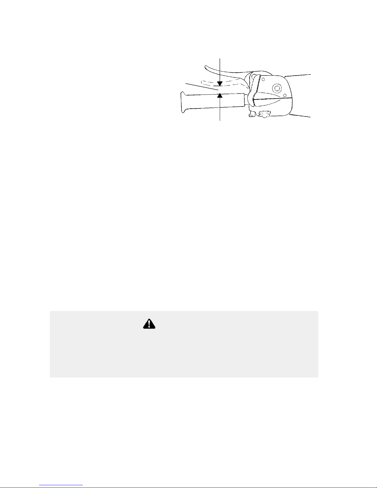
Brake Lever Travel
When the brake lever is
squeezed, it should move no
closer to the handgrip than
1/2″ (1.3 cm) (A). A
distance less than this indicates low brake fluid level or air in the
hydraulic system. Refer to the brake bleeding information on page 92.
Brake Lever Feel
A hydraulic system multiplies the force of your hand squeezing the
brake lever. Proper operation depends on an adequate supply of air and
moisture-free hydraulic brake fluid in the system. If the brake lever
feels “spongy” when squeezed, check the level and condition of the
fluid. Also check for the presence of air in the fluid system. Refer to
page 92 for more information, or see your dealer for s ervice.
Replace brake fluid at least every two years with Polaris DOT 3 high
temperature brake fluid. All DOT 3 brake fluid is not alike. We
recommend that you use only Polaris brake fluid. See page 124 for the
part numbers of Polaris products.
A
Continued use of “spongy” brakes may cause a complete
loss of brakes, which could result in serious injury or death.
Always have the brakes serviced at the first sign of
sponginess.
WARNING
Page 57
55
PRE-RIDE INSPECTION
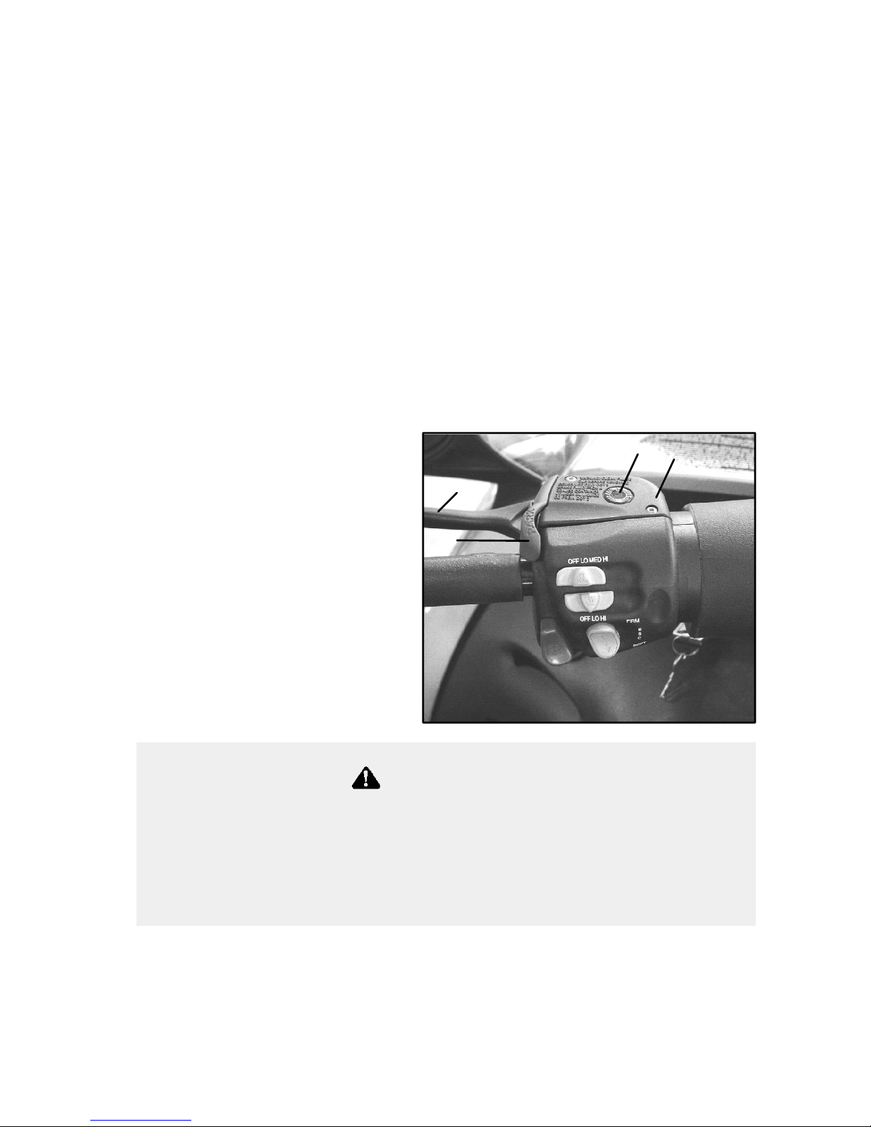
Park Brake Lever Lock
Your snowmobile has a park brake lever lock located over the brake
lever . Use the brake lever lock when you want the machine to remain
stationary; for example, when parked on an incline for a period of five
minutes or less. To apply the lock, squeeze the brake handle and push
forward on the brake lever lock. Hold the lock forward and release the
brake handle.
If the brake handle is squeezed tightly enough, the lock will move
freely into place. Do not force the lock or it may break. To release the
lock, squeeze and release the brake lever. The lever will return to the
unlocked position. The brake light on the console will light up when
the park brake lever is l ocked and the engine is running. It will also be
lit when the service brake is in use. If the brake light does not come on
when the park brake or service brake is in use, have it serviced by your
dealer.
1. Brake Lever
2. Park Brake Lever Lock
3. Master Cylinder Reservoir
and Cover
4. Fluid Level Indicator
4
3
1
2
If the park brake lever lock is partially or entirely engaged while
riding, overheating of the brakes could occur, resulting in brake
damage. In extreme cases it could cause a fire, which could
result in serious injury or death. Always release the park brake
lock before operating the snowmobile.
WARNING
Page 58

56
PRE-RIDE INSPECTION
Steering System
Manually turn the skis completely to the right and to the left. If any
difficulty is encountered, check for ice and snow build-up that may be
obstructing t he steering linkage. Make sure all greasable components
are properly lubricated.
Track Condition
Driving at high speeds for extended periods of time in marginal
lubrication could severely damage track rods, break track edges, and
cause other track damage. Examples of marginal lubrication would
include frozen bodies of water without snow cover, icy trails, and
no-snow conditions.
NOTE: Track damage or failure caused by operation on ice or in poor
lubrication conditions is not covered by warranty.
Hood Latches
The hood of the snowmobile protects the operator from moving parts
and aids i n sound emission control and other functions. Under no
circumstances should your snowmobile be operated with the hood open
or removed.
Oil Level
Always check the oil level on the dipstick before each ride and when
refueling. The dipstick is located on the lower left side of the engine.
Maintain the oil level between the SAFE and ADD marks on the
dipstick. See page 64.
Always inspect the track for damage before using the vehicle.
Operating the snowmobile with a damaged track increases the
possibility of track failure, which could cause loss of control
resulting in serious injury or death.
WARNING
Page 59

57
PRE-RIDE INSPECTION
The following items must be checked before each use of the vehicle.
Check these items after starting the engine (see page 58), but before
putting the machine into motion.
Transmission
Make sure the reverse is not engaged before squeezing the throttle.
Engine Stop Switch
Check the auxiliary shut-off switch for proper operation. Push down to
stop the engine. Pull up to release and start the engine. See page 65.
Tether Switch
If your machine has a tether switch, make sure the engine shuts off
when the tether is removed from the switch. See page 65.
Lights
Check the headlight (high and low beam), taillight, and brake light for
normal operation.
Mirrors
If equipped, adjust your mirrors so they can be used to their full
advantage.
Operating Area
Make sure you have a clear area all around your snowmobile, including
an area clear of bystanders. There’s always the possibility of some
sideways vehicle movement, of applying a little more throttle than
intended, or of debris being thrown by the track. If the surrounding
area is clear you before you start, you can devote your full attention to
operating the snowmobile.
Page 60

58
OPERATION
Starting the Engine
Do not depress the throttle until the engine starts.
1. Pull the kill switch (shut-off switch) up to the RUN position.
2. Turn the key to START and crank the engine. NOTE: There will
be a half second delay before the starter engages to allow the ACS
system to “wake up.”
3. After the engine starts, release the key to the ON position.
NOTE: If the engine doesn’t start on the first attempt when the air
temperature is below -5° F. (-20° C.), wait 15 seconds for the
electrical system to recover, then attempt to start again.
NOTE: The F rontier is equipped with a recoil for emergency starting.
Seepage67.
Before starting the engine, always refer to all safety warnings
pertaining to snowmobile operation. Never start your snowmobile
without checking all components to be sure of proper operation.
See Pre-Ride Inspection section beginning on page 53.
WARNING
Page 61

59
OPERATION
Engine Break-In
No single action on your part is as important to long, trouble-free
machine life as proper break-in of a new or rebuilt engine. During the
first three hours of operation, operate the snowmobile as outlined in
this Engine Break-In section.
Avoid Heat Build-Up
Excessive heat build-up during the first few hours of operation will
damage close-fitted engine parts. Do not operate at full throttle or high
speeds for extended periods during the first 100 miles (160 km)of use.
Vary the throttle openings and m achine speeds to reduce friction on all
close-fitting machined parts, allowing them to break in slowly without
damage.
Perform Fluid Checks
Perform regular checks on fluid levels, lines, and all other important
areas of the machine. Perform the first oil and filter change at 500
miles (800 km). See page 83.
CAUTION
Failure to follow the procedures outlined in the Engine Break-In
section of the owner’s manual could result in serious damage to
the snowmobile. Follow all procedures as outlined.
Page 62

60
OPERATION
Engine Break-In
Lubrication
Always check the oil level when refueling. Oil must be maintained
between the SAFE and ADD marks on the dipstick. See page 64.
We highly recommend the use of only Polaris products for your
snowmobile. We’re continuously testing lubricants and provide the
highest performance products available for your snowmobile’s engine.
See page 124 for the part numbers of Polaris products.
Serious engine damage can occur without the proper lubrication.
Check the oil level often during the first tankful of fuel. Maintain
the oil level between the SAFE and ADD marks on the dipstick.
CAUTION
CAUTION
Mixing brands or using a non-recommended oil may cause serious
engine damage. We recommend the use of Polaris Premium 4
Synthetic 0W-40 engine oil for your snowmobile. Never mix brands.
Page 63

61
OPERATION
Track Warm-Up
Follow these steps to ensure proper warm-up
of the engine, drive train and track.
1. Use an appropriate stand to securely
support the rear of the snowmobile at
the rear bumper. The track should be
approximately 4″ (10 cm) off the
ground.
2. Start the engine and allow it to warm
up two to three minutes.
3. Depress the throttle abruptly and allow the track to rotate several
revolutions. NOTE: It will take longer to warm up the track
sufficiently during colder outdoor temperatures.
4. Release the throttle, apply the brakes, shut off the engine and lower
the machine to the ground.
5. Grasp the skis by their front loops and move them from side to
side. This will loosen frozen snow from the ski bottoms, allowing
the machine to move forward more easily.
6. The engine, drive system and track are now properly warmed up
and the machine may be driven following normal safety practices.
Inadequate cooling and lubrication will lead to overheating of the
slide rail and track, resulting in premature wear and failure.
Reduce speeds and frequently drive into fresh snow to allow
adequate cooling and polishing of the slide rail and track surfaces.
Avoid operating on ice, hard-packed surfaces or roads.
CAUTION
A loose track or flying debris could cause serious personal injury
or death. Stand clear of the front of the machine and the moving
track. Never hold the snowmobile up or stand behind it while
warming up the track. Do not use excessive throttle during
warm-up or when the track is free-hanging. Be sure the rear
support is stable.
WARNING
Page 64

62
OPERATION
Fuel
Gasoline is highly flammable and explosive under certain
conditions.
S Always exercise extreme caution whenever handling gasoline.
S Always refuel with the engine stopped, and outdoors or in a
well ventilated area.
S Do not smoke or allow open flames or sparks in or near the
area where refueling is performed or where gasoline is stored.
S Do not overfill the tank. Do not fill the tank neck.
S If gasoline spills on your skin or clothing, immediately wash it
off with soap and water and change clothing.
S Never start the engine or let it run in an enclosed area. Engine
exhaust fumes are poisonous and can cause loss of consciousness or death in a short time.
The engine exhaust from this product contains chemicals known
to cause cancer, birth defects or other reproductive harm.
Operate this vehicle only outdoors or in well-ventilated areas.
WARNING
WARNING
Page 65

63
OPERATION
Fuel
The fuel used in your Polaris engine is as important to engine life and
performance as the lubricant. Your Polaris engine is designed to run on
a minimum of 87 octane non-oxygenated or 89 octane oxygenated
pump gasoline. There’s a great deal of variability in the quality of the
87 octane gasoline available across the country, so we encourage the
use of premium fuel when possible.
Fuel System Deicers
If you use non-oxygenated fuel, Polaris recommends the regular use of
isopropyl-based fuel system deicer. Add one to two ounces per gallon
(8-16 milliliters per liter) of gasoline to prevent engine damage
resulting from fuel system icing and lean fuel mixtures. Never use
deicers or additives containing methanol. See page 124 for the part
numbers of P olaris products.
If you use oxygenated fuel containing ethanol, additional alcohol
deicers or water absorbing additives are not required and should not be
used.
Using fuels with a lower than recommended octane or operating with
obstructed fuel systems will result in serious engine damage.
Always use the recommended fuels for your machine.
CAUTION
Prolonged exposure to petroleum based products may damage
paint. Always protect painted surfaces when handling fuel.
CAUTION
Page 66

64
OPERATION
Oil
Oil Level
Always check the oil level on the dipstick before each ride and when
refueling. The dipstick is located on the lower left side of the engine.
When the oil reaches the ADD mark, add 8 fl. oz. of recommended oil
to the engine. Maintain the oil level between the SAFE (A) and ADD
(B) marks on the dipstick.
Throttle Position Sensor (TPS)
All throttle bodies have been preset at the factory for adequate fuel
supply at all altitudes. No adjustment is required. Any service must be
performed by a Polaris dealer trained to service EFI systems.
A
B
Any attempt to adjust the TPS without proper tools and training
WILL result in deteriorated engine performance and could result
in SEVERE engine damage. NEVER attempt to adjust the TPS.
Always have your Polaris dealer perform any service on the TPS.
CAUTION
Page 67

65
OPERATION
Engine Stop Switch
Push down on the engine stop
switch (A) to stop the engine in an
emergency. This will ground out
the ignition and bring the engine to
a quick stop. To restart the engine,
the switch must be pulled up to the
ON position.
Throttle Safety Switch
Test the throttle safety switch
system daily before operation.
While seated in a normal riding
position, and with the engine
idling, hold the throttle lever pin
stationary by exerting pressure on
the pivot pin in the direction shown
in the illustration (B). Apply a
slight amount of throttle. A
properly functioning switch must shut down the engine.
The throttle safety switch is designed to stop the engine whenever all
pressure is removed from the throttle lever and the throttle cable or
valves do not return to the normal closed position.
A
B
Operating the snowmobile with a faulty throttle safety switch
can result in serious injury or death in the event of an accident.
If the throttle safety switch does not shut off the engine during a
throttle system malfunction, immediately push down the engine
stop switch. Do not start the engine again until the malfunction
has been corrected by your dealer.
WARNING
Page 68

66
OPERATION
Throttle Lever
If the engine stops abruptly when the throttle lever is released:
1. Turn the ignition switch to OFF.
2. Visually inspect the throttle cable and throttle body to determine
what caused the safety switch to activate.
3. Test the throttle lever by compressing and releasing it several
times. The lever and cable must return to the idle position quickly
and completely.
4. If the throttle lever operates properly, turn the ignition switch on
and go through normal starting procedures.
5. If the engine doesn’t start, take the snowmobile to an authorized
Polaris dealer for service.
Excessive free play in the throttle cable may cause the safety switch to
activate, preventing the engine from starting. If this occurs, see your
authorized Polaris dealer for service.
If an emergency exists and it’s necessary to start the engine, the throttle
safety switch and engine stop switch may be disconnected from the
wire harness. When these switches are disconnected, the ignition key
switch must be used to shut off the engine. DO NOT continue to
operate the machine with the throttle safety switch disconnected. See
your authorized Polaris dealer for service as soon as possible.
An improperly functioning throttle lever may cause erratic machine
behavior and loss of control, which could result in serious injury or
death. If the throttle lever does not work properly, DO NOT start
the engine.
WARNING
Page 69

67
OPERATION
Emergency Stopping
The following chart lists methods for stopping the snowmobile in the
event of an emergency. Refer to page 65 for more i nformation about
the engine stop switch and throttle safety switch.
SYSTEM WHAT IT DOES THROTTLE
CONDITION
Ignition Switch Interrupts ignition circuit All
Brake Slows jackshaft All
Engine Stop Switch Interrupts ignition circuit All
Throttle Safety Switch Interrupts ignition circuit All
Tether Switch (Option) Interrupts ignition circuit All
Emergency Starting
Your machine is equipped with a recoil under the hood for emergency
starting.
1. Turn the key to ON.
2. Pull the kill switch (shut-off switch) up to RUN.
3. Grasp the starter handle and pull slowly until the recoil engages.
4. Slowly pull the recoil handle, rotating the engine until it becomes
harder to pull. The engine is now near top dead center.
5. Allow the rope to partially retract into the recoil (until a
comfortable stance for starting is achieved).
6. Pull the handle abruptly to start the engine.
Excessive or repetitive use of brakes for high speed stops will
cause an overheated brake system. This overheated condition
could cause sudden loss of brakes and/or fire, resulting in
serious injury or death.
When traveling on long downhill stretches, pump the brakes.
Riding the brakes may cause the brake system to overheat and
result in brake failure.
WARNING
Page 70

68
OPERATION
Reverse Operation
Make sure the shift lever is shifted completely into forward or reverse
position. Do not force the shift lever into reverse if resistance is felt.
The gears may not always be aligned for shifting into reverse, and
forcing the lever may cause damage. If resistance is felt, gently apply
the throttle to move the gears to a different position and try to shift
again.
The transmission may not always be in the gear indicated by the shift
lever. Apply the throttle slowly until you’re sure which gear is
engaged.
Sometimes the drive belt will drag in the drive clutch, causing slight
tension in the transmission and making it hard to shift. Shutting the
engine off will remove this tension and ease shifting. This should only
happen during the break-in of a new belt or when the drive/driven
clutch center distance is too long. If this is the case, belt tension
adjustments should be made by your dealer.
Improper reverse operation, even at low speeds, may cause loss
of control, resulting in serious injury or death.
S Always look behind the vehicle before and while backing.
S Always avoid sharp turns.
S Shift to or from reverse only when stopped.
S Always apply throttle slowly.
WARNING
Page 71

69
OPERATION
Daily Storage
At the end of each ride, park the snowmobile
on a level surface and support it at the rear
with an appropriate track stand. The track
should be suspended approximately 4″
(10 cm) off the ground.
Remove the key and cover the machine.
NOTE: Polaris has accessory covers
and track stands available to fit all models. See your dealer for more information.
Page 72

70
OPERATION
Towing
For your safety, do not attempt to use the tow hitch until you’ve read
the following warnings and understand the proper hitch functions.
If the snowmobile becomes inoperable and must be towed, and if it
isn’t possible to use a rigid tow bar, attach the tow rope to the ski
spindles (not to the ski loops) to prevent damage to the steering
components. Remove the drive belt before towing, and have a rider on
the towed snowmobile to operate the brake and steering when
necessary.
Objects towed with a rope have no braking power and can easily
collide with the rear of the snowmobile or other objects, resulting
in serious injury or death. DO NOT tow toboggans, sleds,
saucers, or any type of vehicle with a rope. Only a stiff metal
pole connecting the towed object and the tow hitch on the
snowmobile should be used. If passengers are to be towed on a
toboggan or sled, make sure the pole is at least four feet (1.2
meters) long to prevent any possibility of contact between the
snowmobile’s track and a person riding in the towed object.
Braking distances increase when towing loads. Slow down to
maintain control of the snowmobile.
WARNING
Towing a disabled snowmobile with the drive belt in place can
result in serious damage to the engine and drive system. Always
remove the drive belt from a disabled snowmobile before towing.
CAUTION
Page 73

71
MAINTENANCE
Polaris Recommended Maintenance Program
To ensure many trouble-free miles of snowmobiling enjoyment, follow
recommended regular maintenance and service checks outlined in this
manual.
The recommended maintenance schedule on your snowmobile calls for
service and maintenance inspections at 150 miles (240 km), 500 miles
(800 km), and 1000 miles (1600 km). These inspections should be
performed by a qualified service technician. For continued optimum
performance and component life, continue maintenance checks at 1000
mile (1600 km) intervals.
All necessary replacement parts and labor incurred, with the exception
of authorized warranty repairs, become the responsibility of the
registered owner. If, during the course of the warranty period, part
failures occur as a result of owner neglect in performing recommended
regular maintenance, the cost of repairs are the responsibility of the
owner.
Personal safety is critical when attempting to service or adjust your
snowmobile. If you’re not familiar with safe service or adjustment
procedures and the use of tools, or if you don’t feel comfortable
performing these tasks yourself, contact an authorized Polaris dealer
for service.
EFI System
There are no maintenance adjustments required for the EFI system.
Any service to the EFI system must be performed by an authorized
Polaris dealer with training in EFI systems.
Page 74

72
MAINTENANCE
Maintenance Chart
The following chart is a guide based on average riding conditions. You
may need to increase frequency based on riding conditions. When
inspection reveals the need for replacement parts, always use genuine
Polaris parts, available from your Polaris dealer.
Item Weekly or
before
long trip
150
miles
(240 km)
500
miles
(800 km)
1000
miles
(1600 km)
See
Page
Check brake operation and
adjustment
Daily 54, 89
Test engine stop switch Daily 57
Test tether strap Daily 57
Check track condition Daily 56
Test throttle safety switch Daily 65
Check throttle lever operation Daily 53, 66
Check operation of headlights,
taillight, brakelight
Daily 57, 93
Check park brake function Daily 55
Check oil level Daily 64
Check coolant level Daily 86
Check track alignment X 104
Steering arm and tie rod ends X 106
Check throttle cable condition X -
Check battery fluid level X 113
Check track tension X 42
Check chaincase oil level X 79
Check gearcase o il level X 79
Check drive chain tension X 88
Check drive belt condition X 98
Check for and tighten loose
suspension mounting bolts
X 110
Tighten ski saddle/spindle bolts X -
Check front limiter strap
condition, tighten bolts
X -
Check ski skags - replace when
worn to half original diameter
X 108
Page 75

73
MAINTENANCE
Maintenance Chart
Item Weekly or
before
long trip
150
miles
(240 km)
500
miles
(800 km)
1000
miles
(1600 km)
See
Page
Check Hi-fax thickness, have
dealer replace when worn
X 109
Tighten rear idler wheel bolts X 104
Tighten idler adjust bolt jam nuts X 104
Check spark plug condition, replace annually
X 81
Inspect coolant filter, replace if
necessary
X X X 87
Grease ski pivots X X X 76
Grease ski spindles X X X 76
Grease center steering arm(s) X X X 76
Lubricate steering post support
bracket and pivot (aerosol)
X X X 76
Grease lower steering post pivot X X X 76
Change oil (annually) X X 83
Grease driveshaft bearing
(always perform before storage)
X X 78
Flush chaincase X X 79
Grease rear suspension pivot
shafts
X X 77
Grease jackshaft bearing
(always perform before storage)
X X 76
Lubricate throttle cable X X 78
Check clutch alignment and offset X X 96
Check cooling system level,
specific gravity
X X 86
Inspect fuel filter and replace X X 82
Check brake fluid level X X 91
Inspect fuel lines and replace X 82
Inspect exhaust system for weak
or missing retaining springs
X 84
Inspect exhaust pipe for cracks or
damage
X 84
Inspect clutch sheaves for
damage, wear, belt residue
X 95
Page 76

74
MAINTENANCE
Maintenance Log
Present this section of your manual to your dealer each time your
snowmobile is serviced. This will provide you and future owners with
an accurate log of maintenance and services performed on the
snowmobile.
150 Mile (240 km) Initial Maintenance Inspection
Authorized Polaris Servicing Dealer
Servicing Technician
Date Mileage
500 Mile (800 km) Maintenance Inspection
Authorized Polaris Servicing Dealer
Servicing Technician
Date Mileage
1000 Mile (1600 km) Maintenance Inspection
Authorized Polaris Servicing Dealer
Servicing Technician
Date Mileage
2000 Mile (3200 km) Maintenance Inspection
Authorized Polaris Servicing Dealer
Servicing Technician
Date Mileage
Page 77

75
MAINTENANCE
Maintenance Log
Additional Services Performed
Authorized Polaris Servicing Dealer
Servicing Technician
Date Mileage
Type of Service
Additional Services Performed
Authorized Polaris Servicing Dealer
Servicing Technician
Date Mileage
Type of Service
Page 78

76
MAINTENANCE
Lubrication
Lubricate the suspension and steering components with Polaris
Premium grease at 500 miles (800 km) and annually or about
every 1000 miles (1600 km) thereafter. See page 124 for the part
numbers of P olaris products.
The illustration shows the location of suspension and steering
components. A + indicates a grease point or fitting.
S Grease the left and right spindles. Raise the front end of the ma-
chine to permit better grease entry into the spindle area.
S Lubricate both of the front ski pivots at the fittings as shown.
S Grease the jackshaft and driveshaft clutch side bearings.
S Use an aerosol lubricant on the steering post support bracket.
S Grease the center steering arms.
S Grease the steering post lower pivot.
S Grease the rear suspension pivot shafts (raise the rear of unit).
A grease gun kit, complete with grease and adaptors, is available to
lubricate all fittings on Polaris snowmobiles. See page 124.
+
+
+
+
+
Page 79

77
MAINTENANCE
Lubrication
The suspension pivot shafts should be lubricated with Polaris Premium
All Season Grease at 500 miles (800 km) initially, every 1000 miles
(1600 km) after that, and before off-season storage each year. Lack of
lubrication will adversely affect your ride and the life of the
suspension. For detailed information about suspension lubrication and
adjustments, see your Polaris dealer.
NOTE: Lubrication points are indicated by a L.
M10 Suspension
Edge Touring Suspension
M -10 ACE Suspension
Page 80

78
MAINTENANCE
Lubrication
Jackshaft Bearing
Loosen the driven clutch retaining bolt and pull
the clutch outward to expose the bearing and
grease fitting. Inject grease into the grease
fitting in the flangette until grease purges from
inside or outside the bearing seal (may take
only two pumps). Push the clutch back onto
the shaft and replace the clutch retaining bolt.
Torque to 18 ft. lbs. (24 Nm).
Driveshaft Bearing
Inject grease into the fitting on the speedometer
drive adaptor until grease purges from inside or
outside the bearing seal (approximately two
pumps).
Throttle Cable
Lubricate the throttle cable lightly with
grease or oil. With the engine off, turn
the handlebars to the left and lubricate
liberally as shown.
+
+
+
Page 81

79
MAINTENANCE
Lubrication
Chaincase Oil
Check the chaincase oil level weekly and before any long trips.
Place the machine on a level surface.
Remove the dipstick (A) and read the oil level. The oil level should be
between the SAFE marks on the dipstick. Add Polaris chaincase oil
through the dipstick opening if needed. Do not overfill. Seepage124
for the part numbers of Polaris products.
Flush the chaincase after the first 500 miles, then every 1000 miles or
seasonally. Clean the magnetic plug (B) whenever checking or
changing lubricant.
A
B
Page 82

80
MAINTENANCE
General Maintenance
Spark Plugs
S Use Champion RC7YC spark plugs.
S P roper electrode gap is .035” (.9 mm)
S S park plug torque is 18-22 ft. lbs. (24-30 Nm).
Change spark plugs annually and whenever inspection reveals fouled
or damaged plugs. Always use the recommended spark plugs for your
machine. A spark plug with a heat range too high will cause engine
damage. A spark plug with a heat range too low will cause excessive
fouling and engine malfunctioning.
NOTE: Always carry spare spark plugs in case of an emergency.
Using non-recommended spark plugs can result in serious engine
damage. Always use Polaris-recommended spark plugs.
CAUTION
Page 83
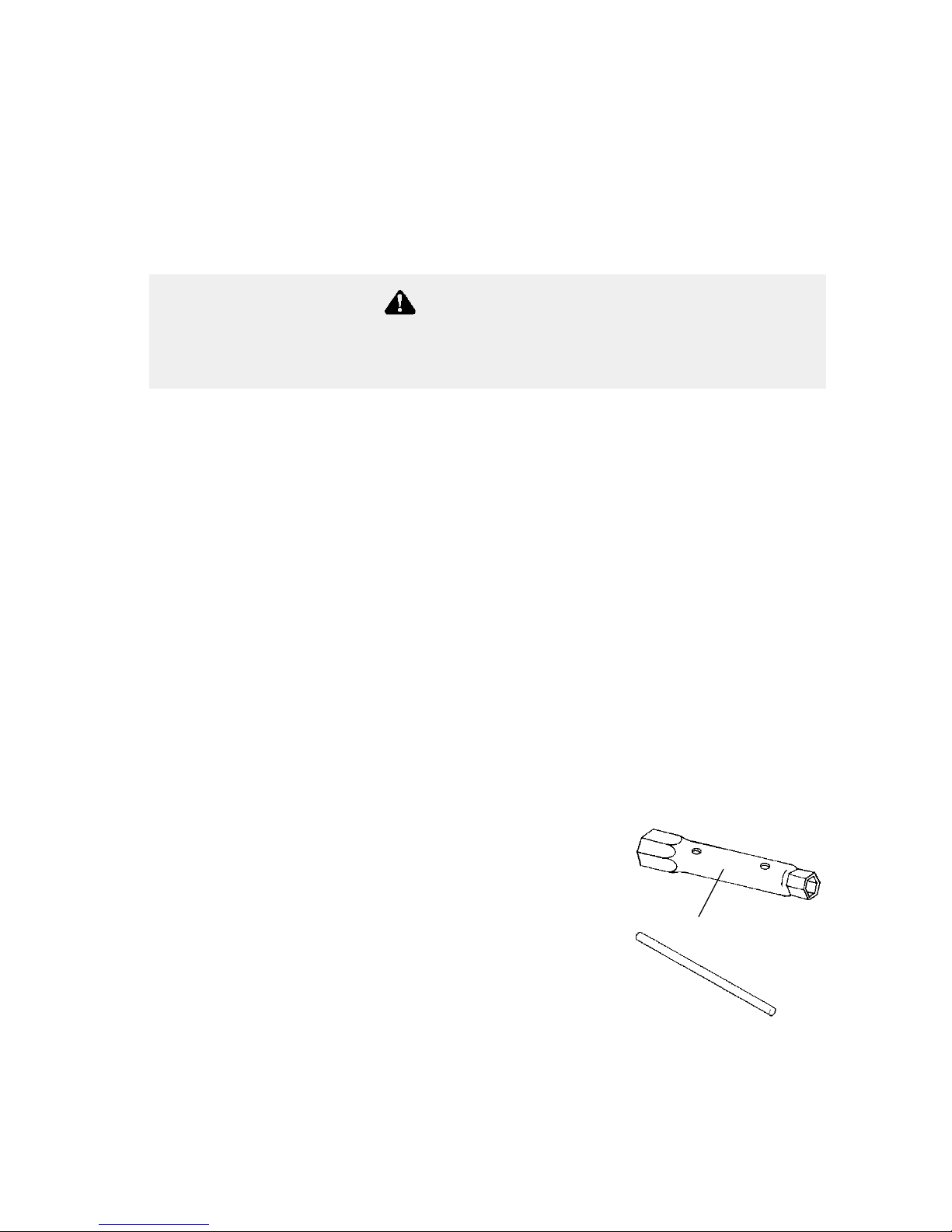
81
MAINTENANCE
General Maintenance
Spark Plugs
Spark plug condition is indicative of engine operation. The spark plug
firing end condition should be read after the engine has been warmed
up and the vehicle has been driven at higher speeds. Immediately
check the spark plug for correct color .
Normal
The normal insulator tip is gray, tan or light brown. There will be few
combustion deposits. The electrodes are not burned or eroded. This
indicates the proper type and heat range for the engine and the service.
NOTE: The tip should not be white. A white insulator tip indicates
overheating, caused by use of an improper spark plug or a faulty EFI
system.
Wet Fouled
The wet fouled insulator tip is black. A damp oil film covers the firing
end. There may be a carbon layer over the entire nose. Generally, the
electrodes are not worn. General causes of fouling are excessive oil or
a faulty EFI system.
Spark Plug Removal and Replacement
1. Remove the spark plug cap.
2. Using the special wrench provided in the
tool pouch, rotate the spark plug
counterclockwise to remove.
3. Reverse the procedure for spark plug
installation.
4. Torque to 18-22 ft. lbs. (24-30 Nm).
5. Install spark plug cap.
WARNING
A hot exhaust system and engine can cause serious burns. Wear
protective gloves when removing a spark plug for inspection.
1
Page 84

82
MAINTENANCE
General Maintenance
Intake Filter
The intake foam filters limit snow ingestion
into the intake system. When operating i n
loose powder snow, check the
filters periodically to remove
any accumulation of snow.
1. Airbox foam filter
2. Air intake box
3. Hood foam filters
Fuel Filter
The best way to check the fuel filter is with fuel pressure. If fuel
pressure is low, remove the filter and check pump pressure. If pressure
is still low, the pump may need replacement. See your dealer. But if
the pump pressure is good after removing the filter, then the fuel filter
is plugged and must be replaced. The fuel filter should last the life of
the machine if the fuel used is always of good quality.
Fuel Lines
Inspect the fuel lines regularly. Give special attention to the system’s
fuel line condition after periods of storage. Normal deterioration from
weather and fuel compounds may occur.
3
1
2
Operating the snowmobile without the intake filters may cause
throttle body icing and result in poor fuel economy or throttle
body malfunction. Always reinstall the filters before operating.
CAUTION
Kinking the fuel lines or using a pliers or similar tools to remove
fuel lines may cause damage to the lines. If a fuel line has been
damaged or kinked, replace it promptly.
CAUTION
Page 85

83
MAINTENANCE
General Maintenance
Oil and Filter Chan g e
The oil in the crankcase must be drawn out through the dipstick hole,
using a Polaris oil vacuum pump (PN PU-46219) or similar tool from
another manufacturer. This type of tool is commonly used in the
marine industry.
1. Position the vehicle on a level surface and run the engine for 2-3
minutes to slightly warm the oil. NOTE: Running the engine any
longer may cause engine overheating. It may also cause the oil to
become too hot for safe removal with the oil vacuum pump.
2. Remove the dipstick and draw out the oil, following the
instructions provided with the oil vacuum pump. Fish the vacuum
tube around in the crankcase to remove as much oil as possible.
3. Place shop towels beneath the oil filter to catch spills. Using an
appropriate oil filter wrench, such as Polaris PN PV-43527), turn
the filter counterclockwise to remove. Dispose of the used oil and
filter properly.
4. Clean the filter sealing surface on the crankcase with a clean, dry
cloth.
5. Lubricate the o-ring on the new filter with a film of new engine oil.
Check to make sure the o-ring is in good condition.
6. Install the new filter and turn by hand until the filter gasket
contacts the sealing surface, then turn an additional half t urn.
7. Add 2 quarts (1.9 ltr) of Polaris Premium 4 synthetic oil through
the dipstick hole. Reinstall the dipstick.
8. Start the engine and allow it to idle for one to two minutes. S top
the engine and inspect for leaks.
9. Check the oil level on the dipstick and add oil as needed to bring
the level to the SAFE mark on the dipstick.
Page 86

84
MAINTENANCE
General Maintenance
Exhaust System
Check the exhaust system for wear or damage at approximately 1000
miles (1600 km). To inspect, allow the engine and exhaust system to
cool completely. Open the hood and inspect the muffler and pipes for
cracks or damage. Check for weak or missing retaining springs or
damper/support grommets.
Engine Cooling
The cooling system on liquid cooled models consists of the following
major components:
S Coolant bottle
S Water pump
S Cylinders
S Heads
S Inlet and outlet manifolds
S Pressure cap
S Heat exchangers
Hot exhaust system parts can cause serious burns. Allow
adequate time for the exhaust system to cool. Never perform
this procedure with the engine running.
WARNING
Page 87

85
MAINTENANCE
General Maintenance
Coolant Mixture
The coolant supplied in the system is a 50/50 mixture of
ethylene-glycol and distilled water. This mixture provides protection
against freezing at temperatures to -34° F (-37° C). If greater
protection is required, the percentage of antifreeze to water may be
increased. Use Premium 60/40 anti-freeze coolant, which is already
premixed and ready to use. Do not dilute with water. See page 124 for
the part numbers of Polaris products.
Never exceed a 60% antifreeze/40% water mixture. Contact you dealer
if greater protection is required.
NOTE: Never add tap water to the cooling system. Minerals cause
deposits and may react adversely with the metals in the engine and
cooling system.
Coolant High Temperature Indicator Light
The high temperature indicator light is controlled by the electronic
control unit (ECU). If the engine coolant reaches a certain
temperature, the ECU completes a circuit that turns the light on. If
you must drive your machine after the high temperature indicator light
has come on, drive slowly and stop frequently to allow the engine to
cool down. See your dealer.
Page 88

86
MAINTENANCE
General Maintenance
Coolant Level
The coolant level in the coolant bottle must
be maintained at the FULL COLD mark (A)
to prevent overheating and serious engine
damage.
The engine coolant level is controlled by the recovery system. The
recovery system components are:
S Coolant bottle
S Engine filler neck
S Pressure cap
S Connecting hoses
Flushing the Cooling System
To ensure that the coolant maintains its ability to protect the engine,
the system should be completely drained every two years and a fresh
50/50 or 60/40 mixture of antifreeze and distilled water should be
added. This service must be done when the engine is cold. Ask your
Polaris dealer to check the coolant when he performs the fall tune-up
on your snowmobile.
A
Operating the snowmobile with insufficient coolant will result in
overheating and serious engine damage. Always maintain the
coolant level as recommended.
CAUTION
Page 89

87
MAINTENANCE
General Maintenance
Bleeding the Cooling System
If the pressure cap needs replacement, contact your dealer for the
correct part. Use of a non-standard pressure cap will not allow the
recovery system to function properly.
1. Remove the pressure cap and fill the coolant bottle with properly
mixed coolant to the FULL COLD mark.
2. Elevate the front end of the machine slightly to aid in bleeding of
the heat exchangers.
3. Add coolant to the coolant bottle to bring the level to the FULL
COLD mark.
4. Start the engine and run at a fast idle for two to three minutes to
allow further bleeding of air.
5. Stop the engine and check the coolant bottle level. Fill as required.
6. Feel the heat exchangers under the running boards. If the system is
bled properly, they’ll be warm to the touch. If they’re not, repeat
step 4. Lift the front of the machine slightly to assist in the
bleeding.
7. Replace the pressure cap and carefully lower the front end of the
machine.
Steam and hot liquids will cause serious burns to your skin.
Never bleed the cooling system or remove the pressure cap
when the engine is warm or hot.
WARNING
If coolant flow becomes restricted, coolant loss, air lock or engine
damage may result. Periodically inspect and/or replace the cooling
system components as needed to prevent restricted coolant flow .
CAUTION
Page 90

88
MAINTENANCE
General Maintenance
Drive Chain Tension
To obtain correct chain tension:
1. Rotate the driven clutch
counterclockwise to move all chain
slack to the tensioner side. Lock
the brake lever lock, or have an
assistant hold the brake lever
firmly.
2. Loosen the adjuster bolt jam
nut (A).
3. Finger tighten the adjuster bolt (B)
until it can no longer be adjusted
by hand, then back off 1/4 turn.
4. Tighten the jam nut while holding
the adjuster bolt.
5. The chain is now tensioned.
Release the brake lever lock.
A
B
Page 91

89
MAINTENANCE
General Maintenance
Hydraulic Brake Inspection
Frequently inspect the brake
lever reserve. Firmly
depress the brake lever and
measure the clearance
between the lever and
handlebar grip. This
distance, called brake lever
reserve (A), should be no
less than 1/2″ (1.3 cm).
Brake pads must be replaced when the brake pad material becomes
thinner than the backing plate (approximately 1/16″). A kit is available
for replacing brake pads. See your dealer.
A
Brake failure during operation can result in serious injury or death.
Properly functioning brakes are vital to your safety. Be sure the
brake pads do not drag on the disc and that brake lever travel is
not excessive.
Always replace brake pads when the brake pad material becomes
thinner than the backing plate (approximately 1/16″).
WARNING
Page 92

90
MAINTENANCE
General Maintenance
Brake Components
1. Brake Caliper
2. Chaincase
3. Brake Disc
4. Backing Plate
5. Brake Pad Material (Replace when thickness is less than 1/16″).
Excessive Brake Lever Travel
Hydraulic brakes are self-adjusting, but if excessive brake pad
clearance develops, as described on page 89, the machine should be
returned to an authorized Polaris dealer for inspection and adjustment.
1
2
3
4
5
Page 93

91
MAINTENANCE
General Maintenance
Brake Fluid
All DOT 3 brake fluid is not the same. We recommend the use of only
Polaris DOT 3 high temperature brake fluid. See page 124 for the part
numbers of P olaris products.
The brake fluid level can be seen through a plastic sight glass in the
brake reservoir. If the fluid is sufficient, the sight glass will be black.
If the sight glass is any color other than black, add brake fluid.
Maintain the brake fluid level between the MIN and MAX marks on
the master cylinder reservoir.
After opening a bottle of brake fluid, always discard any
unused portion. Never store or use a partial bottle. Brake
fluid is hygroscopic, meaning it rapidly absorbs moisture from
the air. The moisture causes the boiling temperature of the
brake fluid to drop, which can lead to early brake fade and the
possibility of accident or severe injury .
WARNING
Keep the master cylinder cover free of dirt and debris. The vent
slits allow for diaphragm movement, and if they become
plugged, movement of brake fluid below the diaphragm may be
restricted, altering brake function.
WARNING
Brake fluid will damage decals, paint and some plastics. Always
wipe up spills immediately.
CAUTION
Page 94

92
MAINTENANCE
General Maintenance
Bleeding the Hydraulic Brake System
Air in the hydraulic brake system will cause spongy brake lever action.
Bleed the system before operating the snowmobile.
During the bleeding procedure, keep the brake handle as level as
possible. The reservoir must be in this position to minimize t he
possibility of air entering the system through the reservoir vent.
1. Remove the brake master cylinder reservoir cover and gasket.
2. Fill the master cylinder reservoir to between the MIN and MAX
marks or 1/4-5/16″ (.6-.8 cm) below the lip of the reservoir
opening. Reinstall the gasket and cover.
3. Slip a rubber tube over the ball of the bleeder valve and direct the
flow of fluid into an approved container.
4. Squeeze the brake lever a full stroke. Then unscrew the bleeder
valve 3/4 of a turn to release air.
5. Close the bleeder valve and release the brake lever.
6. Repeat steps 4 and 5 until fluid flows from t he bleeder valve in a
solid stream free of air bubbles.
7. After bleeding is complete, refill the reservoir to the recommended
level. See page 91.
8. Reinstall the gasket and cover.
Operating the vehicle with a spongy brake lever can result in
loss of brakes, which could cause an accident and lead to
serious injury or death. Never operate the vehicle with a
spongy-feeling brake lever.
WARNING
Overfilling the master cylinder leaves no room for fluid expansion
and may cause the brakes to lock, resulting in serious injury or
death. Always maintain the brake fluid level between the MIN
and MAX marks on the reservoir as recommended.
WARNING
Page 95

93
MAINTENANCE
General Maintenance
Headlight Adjustment
The headlight may be adjusted for
vertical aim using the following
procedure:
1. Place the snowmobile on a level
surface with the headlight
approximately 25 feet (7.6m)
from a wall.
2. Measure the distance from the
floor to the center of t he
headlight and make a mark on the
wall.
3. Start the engine and turn the
headlight switch to high beam.
4. Observe the headlight aim. The
most intense part of the headlight
beam should be aimed 2″ (5.1
cm) below the mark placed on the
wall in step 2. NOTE: Rider
weight must be included on the
seat.
5. Turn the adjustment nut (A),
located inside the hood, just
below the headlamp opening.
Turn the knob in or out as needed
to adjust aim.
25’ (7.6 m)
Lamp Center
Height
2″ (5.1 cm)
A
Page 96

94
MAINTENANCE
General Maintenance
NOTE: Do not touch a halogen bulb with bare fingers. Oil from skin
leaves a residue, causing a hot spot that will shorten the life of the
lamp.
Headlights
Removing Halogen Bulbs - High/Low Beam
1. Pinch the ends of the spring (1)
together and lift until it releases
from the spring retainer .
2. Lift the spring carefully around
the wire harness (2) and flip to
the outside of the housing.
3. With the wire harness attached to
the bulb (3), withdraw the bulb
from the housing.
4. Grasp the bulb by the metal base
and carefully separate it from the
harness.
Installing the Bulb
1. Hold the bulb by the metal base
and install it into the wire harness.
2. Insert the bulb into the housing.
3. Carefully flip the spring back into
the housing, placing it around the
wire harness.
4. Squeeze the spring together until it’s over the spring retainer and
release.
5. Verify headlight aim.
Removing Halogen Bulbs - High Beam
1. Remove the wire harness (4).
2. Gasp the bulb (5) firmly and twist it 1/2 turn counterclockwise.
3. Remove the bulb from the housing and replace it with a new bulb.
4. Place the bulb and housing back inside the hole and turn the
housing 1/2 turn clockwise to lock into place.
5. Reinstall the wire harness to the housing.
2
1
3
4
5
Page 97

95
MAINTENANCE
General Maintenance
Clutch System
Periodically inspect the clutch sheaves for damage, wear, or belt
residue. To maintain optimum performance, clean with non-oil based
cleaners such as isopropyl alcohol.
If you become aware of higher than normal clutch engagement or
an unusual vibration or shift pattern, see your dealer immediately.
Do not operate the machine until repairs have been made.
All clutch maintenance and repairs must be performed by an
authorized Polaris dealer. Any unauthorized modifications to
clutches, such as adding or removing weights, will void the
warranty.
WARNING
The bushings in the weights and rollers of Polaris clutches are
made of a material that may be damaged if lubricated. Do not
lubricate clutch bushings.
CAUTION
Page 98

96
MAINTENANCE
General Maintenance
Clutch Alignment and Offset
Clutch center distance and alignment (A) are
crucial to maintaining optimum performance.
See the specifications section on pages 116-117
for the recommended offset between the drive
and driven clutches with the belt removed.
The drive belt is a very important part of the drive
system. Belt width and length must match the
center distance of the clutches and sheave width of
the drive clutch. For this reason, Polaris
recommends that only O.E.M. belts be used.
Other belts may match the dimensions, but can
drastically change the shift pattern, resulting in
poor performance. See your dealer for service and
adjustments.
NOTE: A worn belt will continue to function,
but will not deliver maximum performance. Always carry a spare belt in case of an emergency.
A
Page 99

97
MAINTENANCE
Frontier Classic Clutching Chart
Altitude
Meters (Feet)
Shift
Weight
Drive
Clutch
Spring
Driven
Clutch
Spring
Driven
Helix
Chaincase
Gearing
0-900
(0-3000)
10-62 Yellow Silver R-11
#2
19:39 72P
HYVO
900-1800
(3000-6000)
10-62 Yellow Silver R-11
#2
19:39 72P
HYVO
1800-2700
(6000-9000)
10-58 Yellow Silver R-11
#2
17:39 72P
HYVO
2700-3700
(9000-12000)
10-56 Yellow Silver R-11
#2
17:39 72P
HYVO
Frontier Touring Clutching Chart
Altitude
Meters (Feet)
Shift
Weight
Drive
Clutch
Spring
Driven
Clutch
Spring
Driven
Helix
Chaincase
Gearing
0-900
(0-3000)
10-62 Yellow Silver R-11
#2
20:41
74P
900-1800
(3000-6000)
10-62 Yellow Silver R-11
#2
20:41
74P
1800-2700
(6000-9000)
10-58 Yellow Silver R-11
#2
19:41
74P
2700-3700
(9000-12000)
10-58 Yellow Silver R-11
#2
19:41
74P
Page 100

98
MAINTENANCE
General Maintenance
Periodically check the condition and tension of the drive belt, and
always carry a spare belt. For improved drive-away during extremely
cold temperatures, remove the belt and warm it to room temperature.
Reinstall it before starting the snowmobile.
Drive Belt Removal
1. Be sure the key switch is off and the engine has come to a
complete stop. Apply the brake and lock the parking brake.
2. Open the hood, remove the clutch guard retaining pin and open the
clutch guard.
3. Firmly grasp the belt midway
between the clutches and pull
upward and rearward to remove.
See illustration.
 Loading...