

Page 1

Thank you for purchasing the
Polaris Ford Ranger FR-1516
in-dash unit.
Before removal and installation, be sure to thoroughly read these instructions.
Keep these instructions with your vehicle records for future reference.
FORD RANGER FR-1516
Installation Instructions
This installation guide is for reference only. Polaris takes no responsibility for any damage
caused to any vehicle through incorrect installation, unsafe practices or poor workmanship.
Warranty for this product is 3 years from date of purchase, however warranty will be void if :
• The unit is tampered with, damaged or modified in anyway.
• Reverse camera cable is cut or modified in any way
• Reverse camera is subjected to over voltage
• The Navigation SD card is damaged or tampered with in any way
(this includes installing foreign mapping or software onto the SD card)
Warranty Terms
The Ford Ranger FR-1516 is covered for 3 years and includes:
• Defective Equipment
• Defective Cables
Not Covered under warranty:
• Abuse
• Improper installation
• Alteration to cables (this includes cutting of any cables)
• Accidents
If you have any questions concerning the installation, warranty or the operation of the unit,
please contact
Polaris
on
1300 555 514.
We hope that you enjoy the Ford Ranger FR-1516 in dash unit.
Page 2
Prior to installing the unit, please make sure that you have all
the parts from the box and the necessary tools to complete the
installation.
1. Trim tools
2. Cable ties
3. Soldering Iron & Solder
4. Electrical Tape
5. Heat shrink
6. Burner for Heat shrink
7. Step through drill
8. 7mm socket
9. Multi tip set
10. Side cutters
11. Drill/Philips head screwdriver
12. Split conduit
13. Yellow Tongue (long strike,
approx. 3-4 metres)
14. Short strike (approx. 1 metre)
15. Power cable
16. 10mm spanner
1. FR-1516 Head Unit
2. Wiring Harness
3. GPS Antenna
4. Rear Vision Camera with
7m cable
5. Forward Vision Camera
with 7m cable
6. User Manual
2
Tools required
QUICK REFERENCE GUIDE
When the manual refers to ‘OEM’, this means original equipment manufacturer.
When the manual refers to ‘OEM multimedia unit section’ this is the area located where the
OEM 3.5” screen was originally mounted.
When the manual refers to the ‘TOP SECTION’ this is the area located where the top dashboard tray was originally
mounted.
5
4
2
3
1
Parts - Packing List
Page 3
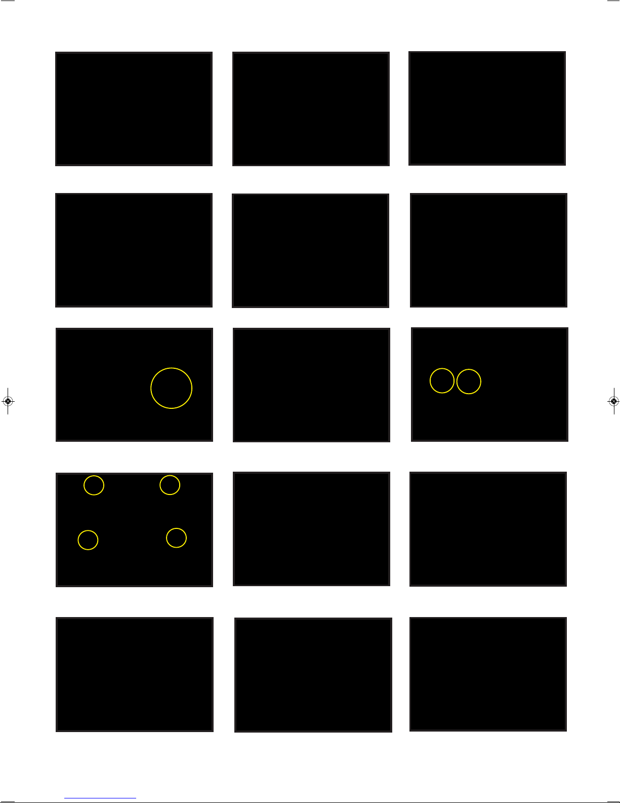
Section 1 - Removal of the dash panel
12. Remove 4 screws located around the
3.5” screen.
3
1.Use your trim tool to remove the
top dash board tray
2. Remove passenger side air vent trim
4. Remove 2 x dash side panels (driver and passenger side)
5. Remove dash trim
10. Pull the 3.5” LCD/CD housing/Air
conditioning controls fascia out gently.
11.Disconnect plugs from the back
of the fascia.
13. Pull screen out gently and
disconnect plugs from the back
3. Remove air vent trim to the left
of steering wheel
6. Remove screw located left and right
of power socket trim.
7. Pull the power socket trim out slightly
and disconnect the plugs
8. Remove 2 screws from behind the
power socket trim
9. Remove 4 screws from around OEM
multimedia unit fascia.
14. Don’t forget to disconnect the plug
in-between the screen and piece behind
Page 4
4
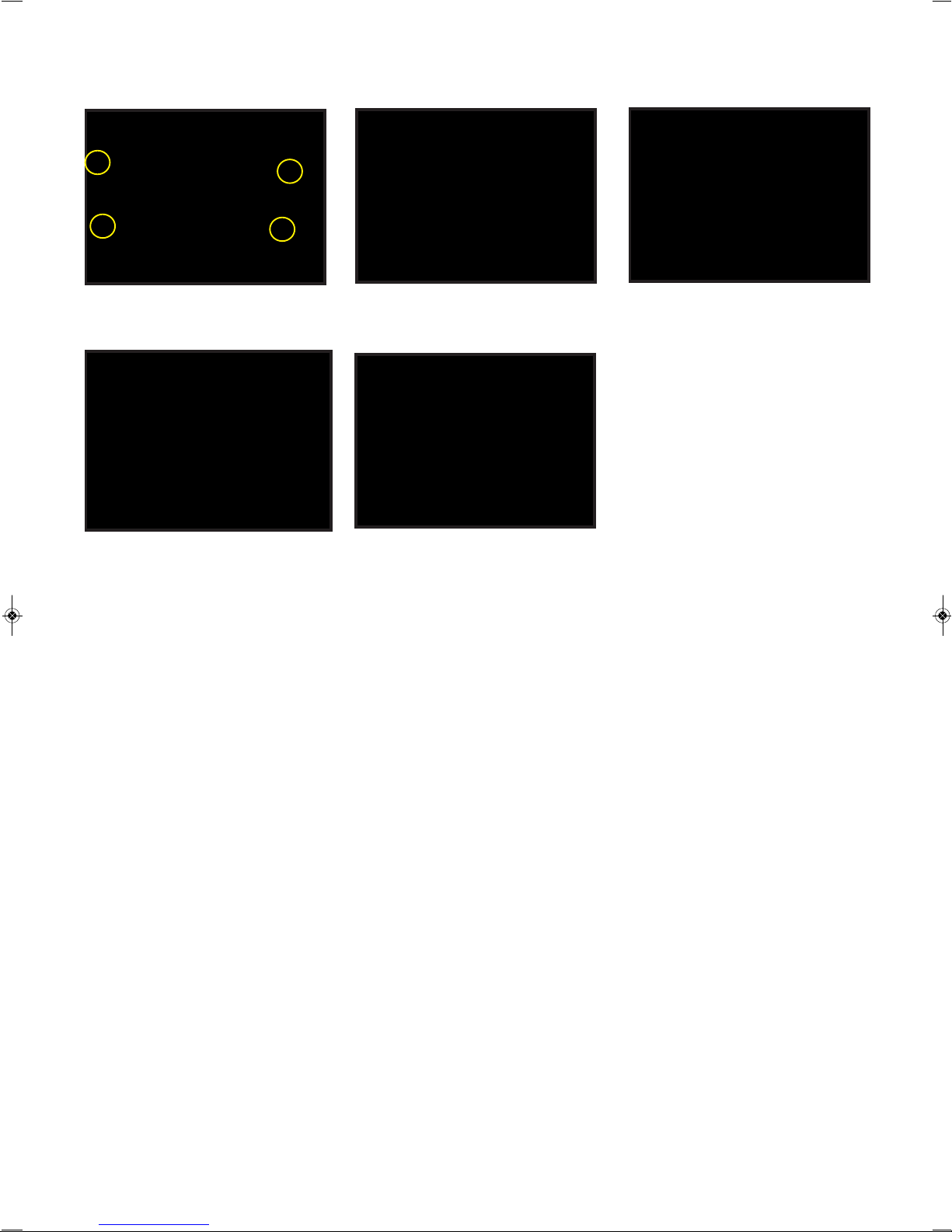
Section 1 - Removal of the dash panel continued
15. Remove 4 screws from around the
CD housing
16. Pull CD housing out gently and
disconnect plugs from the back.
17. This is now what the dash should
look like
19. Run the other end of the harness so
that it sits behind the OEM multimedia
unit section.
18. Use a step-through drill to cut a hole
in the top section so that you can feed the
FR-1516 plug through
Leave this section for now and run your forward vision camera and rear vision camera
Page 5

5
Section 2 - Forward vision camera installation guide
1. Push sides of glove box in to release
2. Disconnect camera from cable and pass the
smaller 4 pin plug through large grommet
(located to the left hand side of firewall).
3. Open front bonnet of Ford Ranger
4. Pull the camera cable through grommet
5. Run cable down the side of
engine compartment
6. Remove radiator support cover
Important
Make sure you leave enough
cable inside the glove-box area
so that you can run the larger
4-pin plug to the section
behind the OEM multimedia
unit
Please note -
The next set of instructions are a guide only.
We have decided to mount the forward vision camera on the bumper bar which means that a 6mm hole needs to be
drilled into the bumper bar. If you wish to position the camera elsewhere, you may need to create some sort of
bracket so that the forward vision camera can be mounted.
7. Drill a 6mm hole in the bumper bar and
feed cable through.
8. Grab a 10mm spanner, hold camera on one side and tighten nut inside bonnet.
Page 6

6
9. Connect camera plug to cable that
should be located inside front bonnet.
Section 3 - Reverse camera installation
1. Run your long strike through chassis rail from front to rear.
2. Tape camera cable (large 4 pin din) and power cable onto strike at the rear of the vehicle.
3. Pull strike through from front of the vehicle - making sure that you leave enough cable at the
rear so that you can plug the camera cable in and can pick up power from the tail light.
6. Connect camera plug to the extension cable.
Apply heat shrink over connection to avoid the
plug coming loose.
7. Release back tray
8. Unscrew 2 screws to release passenger side tail light.
4. Attach the number plate camera onto
number plate (as shown above)
5. Mount number plate back
onto the vehicle.
Section 2 - Forward vision camera installation guide continued
Plug larger 4 pin plug
into front camera
connection on harness
located in the section
behind OEM multimedia
unit.
Page 7

12. Lift carpet up to find grommet
10. Reinstall tail light.
11. Remove kick panel and scuff plate on
passenger front side of vehicle
9. Tap into reverse positive wire
(red with yellow stripe.)
13. Remove grommet and feed cable through.
14. Use cutters to make an incision in
grommet so that you feed cable through it.
Once you have fed the cable through the
grommet, restore grommet back into its
original position.
15. Pull excess cable then apply
conduit to all exposed cable.
16. Run reverse camera cable up into
glove box area.
Notes:
Once you have repositioned the grommet after feeding the reverse camera cable through, we recommend applying
silastic around the outside the cable for waterproofing.
Once you have fed all camera cables - we recommend that you cable-tie any loose cabling.
7
Note
Feed reverse camera cable /
power cable to the area
behind the OEM multimedia
unit. Connect camera plug into
back camera connection and
attach power cable to back
wire on harness.
Section 3 - Reverse camera installation continued
Page 8

Front camera
Back camera
Caravan camera
GPS antenna plug
8
Section 4 - Wiring Diagram
Yellow (Batt+) tap into OEM CD/Radio plug Refer to section A.
Black (Gnd -) tap into OEM CD/Radio plug Refer to section A.
Red (Acc) tap into 12 volt from kick panel Refer to section B
Orange (Illumination) tap into OEM illumination via
traction / diff lock button OEM plug Refer to Section C.
Brown (Back) tail light Refer to reverse camera
installation instructions
Suggested areas to pick up power from
Page 9

9
Section 4 - continued
Section A
Section B - How to tap into 12 volt power in kick panel
Black (ground) pick up from OEM CD/radio
plug (black with purple stripe).
Yellow (batt +) pick up from OEM
CD/radio plug (white with brown stripe).
1. Remove headlight switch trim cover
and pull out gently to disconnect plugs from
the back
2. Remove fuse cover
3. Remove 2 screws holding trim underneath steering column and remove with trim tool.
4. Remove scuff plate on driver’s side.
5. Remove kick panel trim on driver’s sid.e
6. Feed ACC cable through to kick panel
area and tap into 12 volt power
(yellow with white stripe).
Page 10

10
Section C -
How to tap into OEM illumination via traction/diff lock button OEM plug
1. Use trim tool to remove trim around gear-stick. Pull out gently so that you can disconnect
USB/AUX and plug from behind trim.
2. Tap into illumination wire (brown)
via the traction control/diff lock button
OEM plug
Please note:
Please ensure that you solder wires together and cover with electrical tape so they do not come loose.
Section 5 - GPS External Antenna
We no longer recommend mounting the GPS Antenna underneath
the dashboard; please mount it on top of the dash in the right /left
top corner near the windscreen.
Page 11

11
Section 6 -
Mounting the head unit
1. Grab the FR-1516 in-dash and plug in
the main harness.
1. Plug your GPS antenna plug
into FR-1516.
3. Push FR-1516 into place.
IMPORTANT
Before putting the dash back together, power the unit up and test all features.
Section 7 -
Recommended order for putting the dash back together
1. Reinstall trim around gear stick.
2. Reinstall OEM 3.5” screen.
3. Reinstall CD housing.
5. Reinstall power socket trim.
6. Reinstall dash trim.
7. Reinstall air-vent trim to the left of
steering wheel.
8. Reinstall passenger side air-vent trim.
9. Reinstall side panel trim passenger side.
IMPORTANT
Please remember to plug all OEM cables and reinstall all screws as necessary.
4. Reinstall 3.5” LCD/CD housing/
air conditioning controls fascia (make sure
you insert lip under dash pad otherwise the
fascia won’t sit in properly).
Page 12

12
10. Reinstall trim underneath steering
wheel column.
11. Reinstall side panel trim driver’s side.
12. Remove air vent trim to the right
of the steering wheel.
13. Reinstall headlight switch trim.
14. Reinstall air-vent trim to the right
of steering wheel.
15. Reinstall fuse cover trim.
16. Reinstall kick panel trim.
19. Finished product.
17. Reinstall scuff plate.
18. Reinstall your glove box.
Section 7 - Recommended order for putting the dash back together continued
 Loading...