

Page 1
Owner’s Manual
E
Personalized Automated Control System
Page 2

Important Information
WARNING: RISK OF ELECTRICAL SHOCK.
Read and follow operation and maintenance instructions carefully.
•
• Electrical work should be performed by a licensed electrician and conform to all national, state and
local codes.
• Do not have equipment serviced if precipitation is present or imminent.
• Always keep command center door closed when not accessing display panel.
• Do not allow children to handle this product.
• The Eos Wireless Remote requires a fully charged battery at startup.
hours before use. An inadequate charge can permanently damage the battery.
For customer service or support:
• Please mail Warranty Card immediately.
• For on-line support: www.polarispool.com
• To contact Polaris:
US and Canada
Customer Service
2620 Commerce Way
Vista, CA 92081-8438
1-800-822-7933
Charge battery for at least 5
Page 3
E
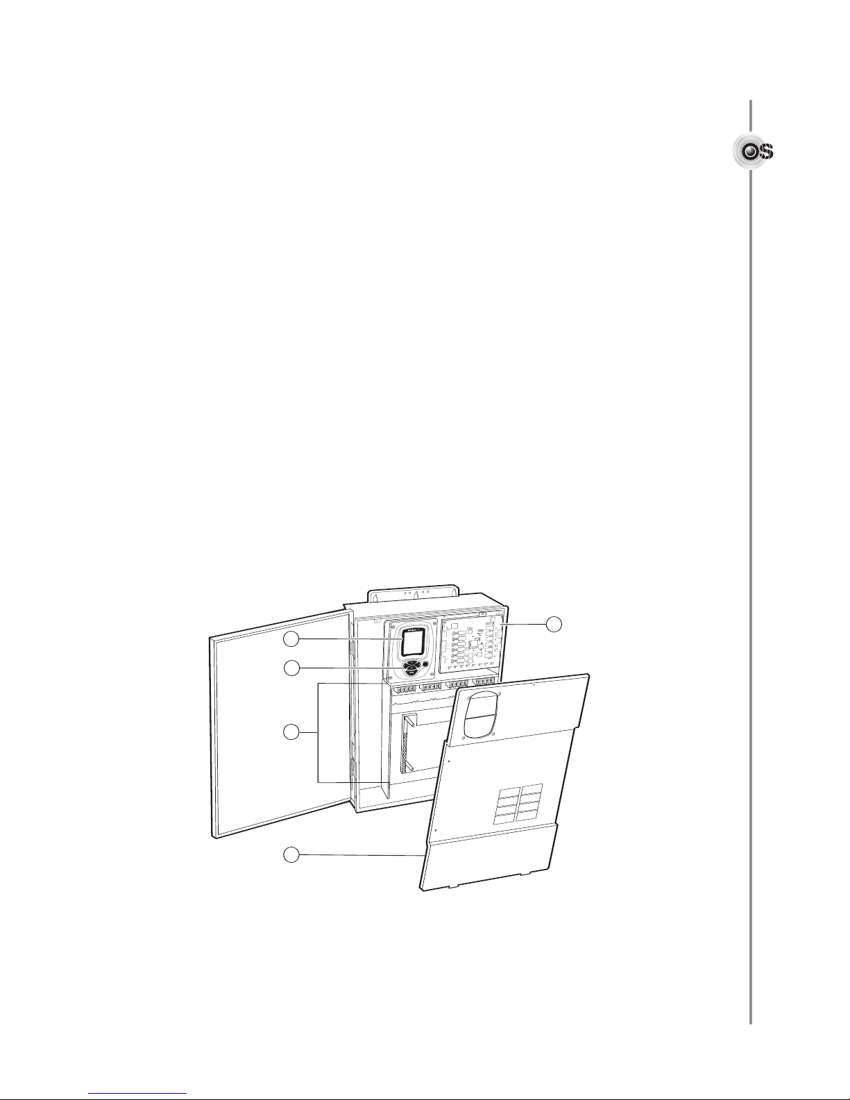
Command Center Open
with Deadfront Removed
E
S
V
C
G
N
D
S
N
S
R
1
G
N
D
SN
S
R
2
G
N
D
S
N
SR
3
G
N
D
SN
SR
4
G
N
D
S
N
S
R
5
+
2
4
V
D
C
G
N
D
P
R
E
O
U
T
L
P1
L
P
2
LP
3
L
P
4
L
P
5
LP
6
V
L
V
6
V
L
V5
V
L
V4
V
L
V3
V
L
V
2
V
L
V
1
2
5
3
1
2
4
1
3
5
Introduction
ongratulations on the purchase of your new automated control system and thank you for
C
choosing Polaris. Designed to provide easy and convenient control of most pool and spa
functions, the Polaris Eos Command Center:
• Controls pool and spa equipment, waterfalls, fountains, and lighting.
• Schedules regular pool and spa routines such as cleaning and circulation.
• Can be programmed to operate multiple devices with the touch of a single button.
• Components, options and functions can be expanded after installation is complete.
• Operates independently or can be remotely controlled from optional in-house wired
remotes, wireless remotes or the Shortcut spa-side remote.
• Remotely operates electric devices including household appliances with the
optional PLC (Power Line Carrier) Kit.
• Controls optional sanitation equipment including traditional chemical or salt
chlorination systems.
Command Center Components
1. Command Center Display
2. Command Center Keypad
3. Relays and Power Subpanel
4. Deadfront
5. Activator Circuit Board
1
Page 4
Aug
Aug
E
System Overview
Device Setup
S
cenes & Shortcuts
Owner Info
Polaris Info
S
tandby
Freeze Protection
Temperature
Fahrenheit
Date Aug 03, 2004
Time 02:04pm
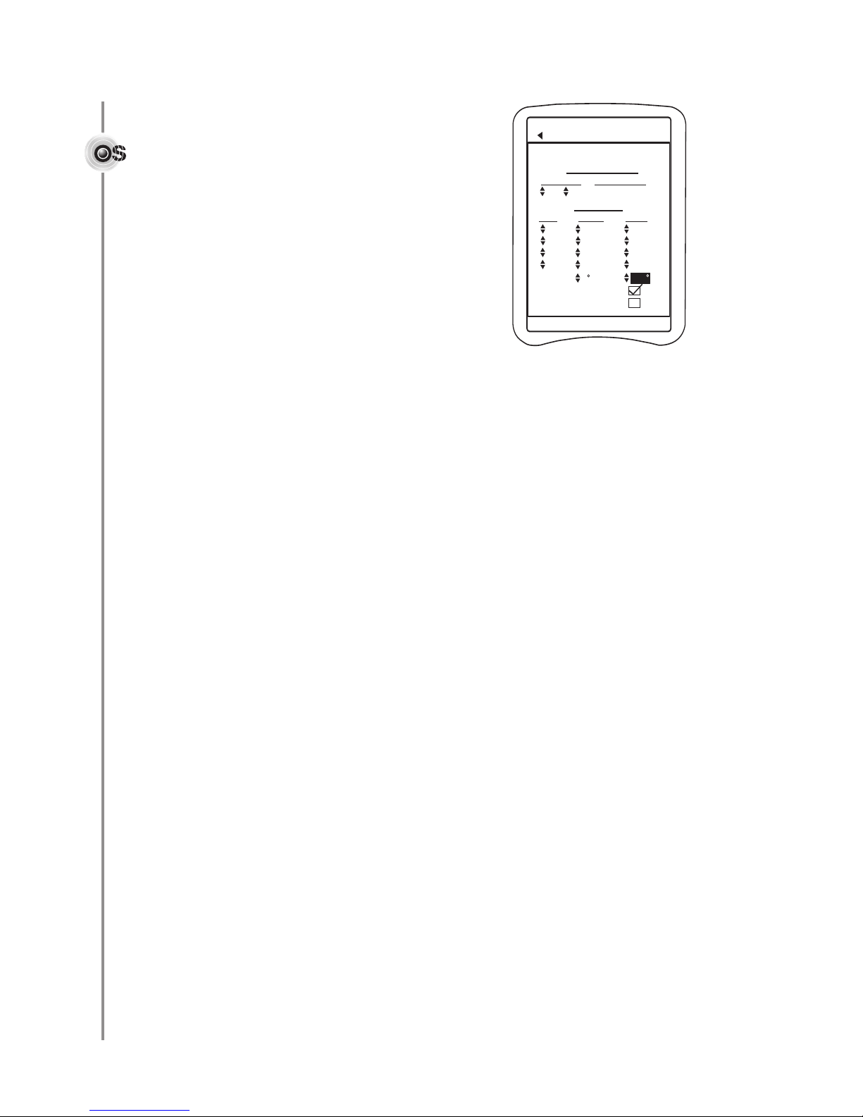
Setup
Tue, Aug 03 2:04 pm
ENTER
To adjust display setting s,
press and together.
SVC
E
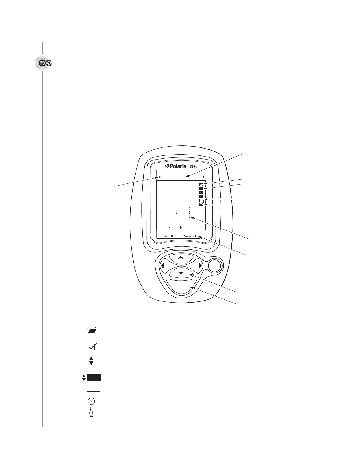
Use left or right
arrow keys to
change screens
Cursor Control
Item Select
Check Box
(Device or function Off)
(Device or function On)
Folder
(Selected)
(Not Selected)
Screen Name
Up/Down Arrow
indicates adjustment
options are available.
Current Status and
Alarm Messages
Starting the Eos Command Center
To activate: Turn on circuit breaker (main power source) to power up the unit.
To disable or put in “Standby Mode”: Press and hold the Enter key for five seconds.
Press any key to reactivate.
To shut down: Turn off main power source to command center.
Display Overview
Display Symbols
olders indicate that additional screens, men
F
or an item.
f
Chec
Up/Do
next to it and the up/down arrow keys are used to select or enter the setting.
Item in reverse (white text on black box) indicates curser is over item or field.
Asterisk in front indicates a text field (blank line) that can be named by user.
k ne
Cloc
Flame ne
es are used to turn functions or devices on or off. Checked = On.
x
k Bo
wn Arro
w indicates adjustment options are a
xt to equipment status field means de
xt to status field of heater means heater is fir
u or setup options are available
ailable for the field
v
vice is scheduled to be
ing.
2
“on.
”
Page 5
Screen Overviews
E
Device Setup
Scenes & Shortcuts
Owner Info
Polaris Info
Standby
Freeze Protection
T
emperature
F
ahrenheit
Date Aug 03, 2004
Time 02:04pm
Setup
Tue, Aug 03 2:04 pm
T
o adjust display setting s,
press and together.
Air 60° Water 60°
Pool Setpoint 71°
Spa Setpoint 100°
Pool Circulation Spa
Cleaner Pump Off
Pool Light Off
Pool Light Dim Off
PS Heater On
Suction Valve Off
Return Valve Off
Cleaner Valve Off
Music On
Table Lamp Off
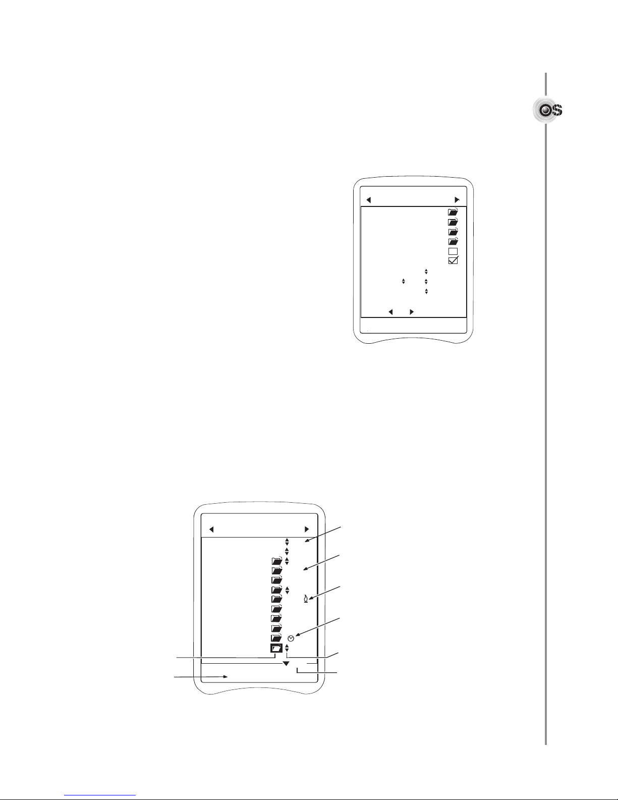
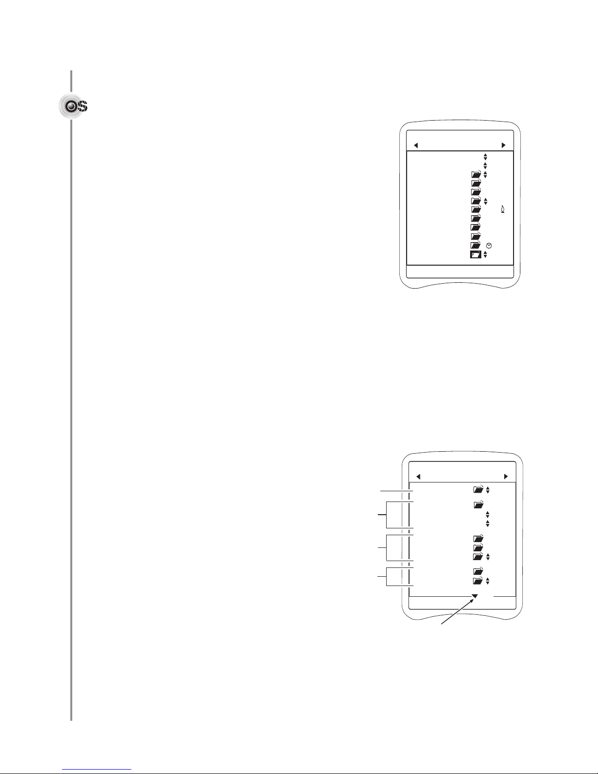
Main
Tue, Aug 03 2:04 pm
Air 60° Water 71°
Indicates device list continues
on another screen
Select folder icon to
open the Device Manager
screen where scheduling
and other operational
functions are controled
Shows designated heater
(set point) temperture
Flame indicates
heater is firing
Indicates adjustable settngs
are available for the device
Clock indicates device
is scheduled to be “On”
Status field indicates
On/Off status of device
More
Shows current sensor
temperature readings and
alerts if any are present
Setup Screen
During installation, this screen is used to define and configure the system.
Adjustments to this screen will usually be minimal. For a complete
escription of system setup and the associated screens, refer to the
d
Eos Installation and Operation Guide.
Device Setup is used to setup system equipment.
Scenes & Shortcuts can be established to start or stop
several devices with a single command.
Owner Info is used to input of owner name and address.
Serial number and service contact phone numbers can
be input in
Polaris Info.
Checking the
Standby box disables all automatic
control functions.
Freeze Protection should always be checked to protect
equipment from freezing conditions.
Temperature sets Fahrenheit or Celsius.
Date by month, day and two-digit year.
Sets
Sets Time along with an am or pm designation.
Optional Device Control Screens
If a Watermatic pH/ORP controller or salt chlorinator is installed, additional control
screens become available.
Main Screen
Once setup is complete, the Main screen provides access to most commonly needed
measurements and functions. Most routine maintenance and adjustments can be made
from this screen.
3
Page 6
Device Manager Screens
E
Tue, Aug 03 2:04 pm
PS Heater Manager
Duration Remaining
04h 00m 00h 00m
Manual Control
S
chedules
P
S Heater Off
Day Start Stop
off 12:00p 12:00p
off 12:00p 12:00p
off 12:00p 12:00p
off 12:00p 12:00p
Range 0
1
04
Heater Cool Down
Freeze Protect
Air 60° Water 71°
Each piece of equipment controlled by Eos has
manager screen with specific settings for the
a
device.
rom these screens equipment can be:
F
• Turned on or off
• Set for specific on or off durations
• Scheduled to be active at specific times
on specific days
Navigating the System
• Use the keypad arrow (cursor control) keys
to move through the screens and
menu options.
• When the cursor is over an item, it will appear darkened or in reverse (white on black
instead of black on white).
• Press the Enter key to select an item, open a folder, or activate/deactivate a feature
with a check box.
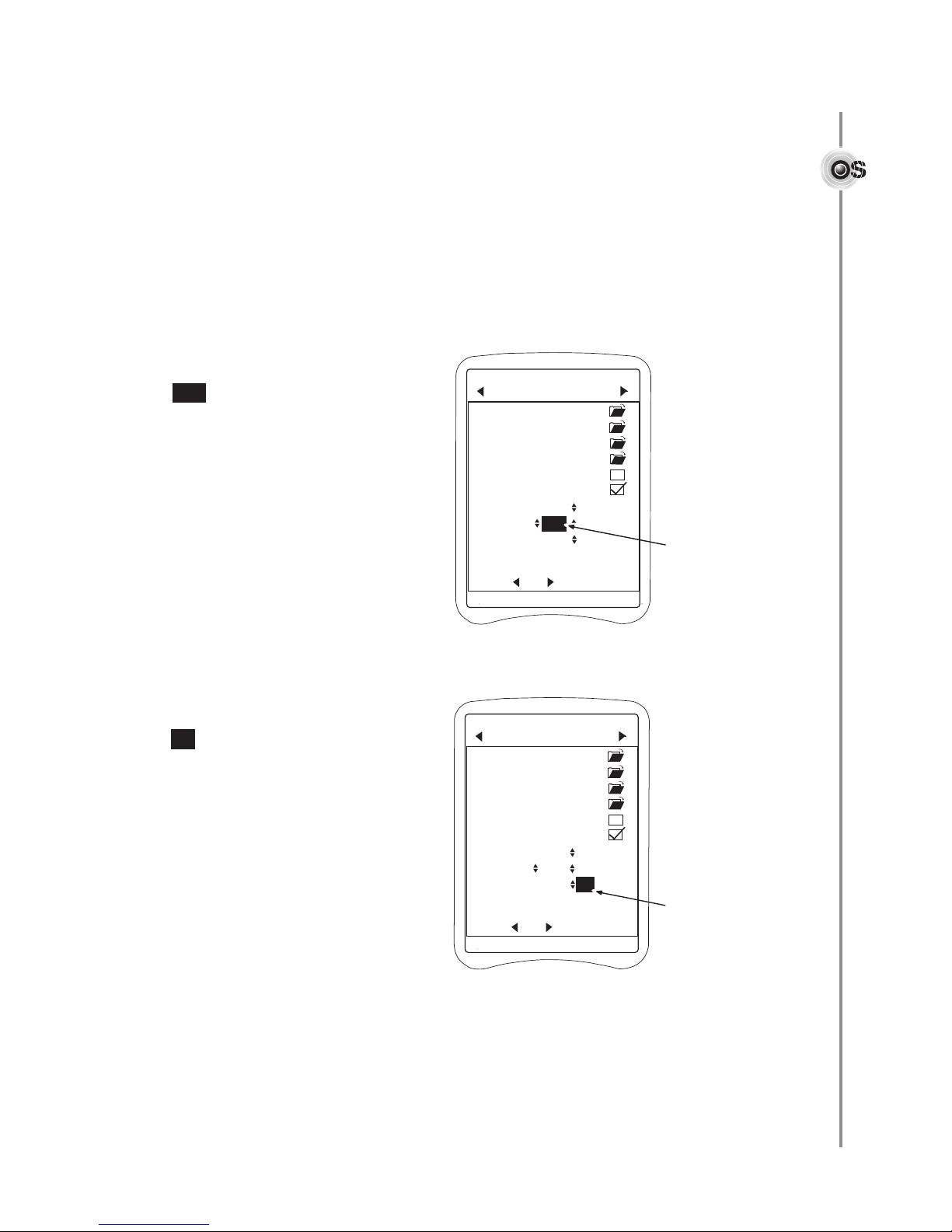
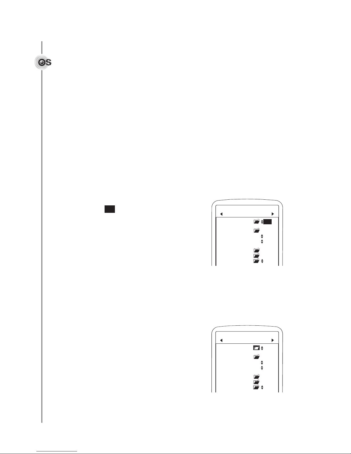
To set or adjust an item:
1. Use the keypad arrow keys to move the cursor over the item.
2. Press <Enter> to select the item. The item will flash.
3. Use the up/down keys to choose or enter the setting.
4. Press <Enter> to activate the setting.
Using text fields
1. Move cursor over the text field and press <Enter> to select.
Use the up/down arrow keys to move through the alpha-numeric options.
2.
3. Use the right arrow key to move to the next position within the field.
4. Press <Enter> when the entry is complete.
Using nameable text fields
1. Move cursor over name field and press <Enter> to select. The last letter
of the name will blink.
2. Use the left arrow key to erase the item name.
3. Use the up/down arrow keys to access the alpha-numeric options.
4. Use the right arrow key to move to the next position within the field.
5. Press <Enter> when the entry is complete.
To change the item back to “None,” move to the asterisk and press <Enter>.
4
Page 7

E
Using the Eos System
Command Center Setup
Tue, Aug 03 2:04 pm
Adjustment
is available
Name of feature
or control
Software Versions
Contrast Adjust
Backlight Adjust
B
acklight Timeout 0 min
Audible Alarm
Cursor is over
adjustable field
o adjust the brightness or contrast of the display, press the left and right arrow keys
T
simultaneously to open the Command Center Setup Screen.
Software Version provides access to information on the current software versions for
the command center and the various devices it controls.
Contrast controls readability of text, light or dark, on screen.
Backlight controls the illumination of screen.
Backlight Timeout sets a time limit for inactivity after which the light on the display
turns off. Hit any key to reactivate the display.
When checked,
sounds when an alert condition exists. (If remote devices are used to control the Eos,
the alarm for each device can be enabled or disabled independently.)
To set or adjust any of the display controls:
1. Use arrow keys to move the cursor over the
field to be adjusted. (Ex: )
2. Press <Enter> to select the item. The item will flash.
3. Use up arrow to increase or down arrow to decrease
screen effect until it is at desired setting.
Press <Enter> to activ
4.
Press the left arrow key to return to the
Audible Alarm enables the alarm within the Command Center that
Adjust
ate setting.
Main screen.
5
Page 8
E
Common Tasks
Pool Circulation Pool
PS Heater Off
Pool Setpoint 71°
Spa Setpoint 100°
Cleaner Pump Off
Pool Light Off
Pool Light Dim Off
Music On
Table Lamp Off
Main
Tue, Aug 03 2:04 pm
More
Circulation
Mode
Heater
Items
Pool
Items
PLC
(X-10)
Items
Indicates device
list continues on
another screen
Air 60° Water 71°
Pool Setpoint 71°
Spa Setpoint 100°
Pool Circulation Spa
C
leaner Pump Off
Pool Light Off
P
ool Light Dim Off
PS Heater On
Suction Valve Off
Return Valve Off
Cleaner Valve Off
M
usic On
Table Lamp Off
Main
Tue, Aug 03 2:04 pm
T
o adjust display settings,
press and together.
Air 60° Water 71°
Changing the Heater (Setpoint)
Temperature Setting
On the Main screen:
1. Move the cursor to the Up/Down Arrow symbol next
to the pool or spa (setpoint) temperature setting.
2. Press <Enter> to select the item.
3. Push the up or down arrow key to change
the temperature setting.
Turning Equipment On or Off
On the Main screen or De
vice Manager
screen:
1. Move the cursor to the Status field next to the device.
2. Press <Enter> to change the status, turn it on or off.
Customizing the Main Screen Display
Items can be reordered or devices grouped to make the system easier to work with.
To move an item up or down on the menu:
1. Move the cursor to the Status field of
the particular device.
2. Press and hold <Enter>.
3. Push the up or down arrow key to
move the device.
o insert a space between menu items:
T
1. Move the cursor to the Status field
ou want to insert a
of the de
line abo
2. Press and hold <Enter>.
3. Press the up and down arrow keys
simultaneously. A space will be
inserted above the item.
o delete the space
T
item bac
vice y
.
e
v
k up
, move the
.
6
Page 9
E
Setting the Time and Date
Setup
T
ue, Aug 03 2:04 pm
To adjust display settings,
press and together.
Air 60° Water 60°
Month is
selected
Device Setup
Scenes & Shortcuts
Owner Info
Polaris Info
Standby
Freeze Protection
Temperature
Fahrenheit
Date Aug 03, 2004
Time 02:04pm
Setup
Tue, Aug 03 2:04 pm
To adjust display settings,
press and together.
Air 60° Water 60°
Device Setup
Scenes & Shortcuts
Owner Info
Polaris Info
Standby
Freeze Protection
Temperature
Fahrenheit
Date Aug 03, 2004
Time 02:04pm
Hour is
selected
t is imperative that the date and time are set correctly to ensure proper function of the
I
equipment scheduling features.
he command center offers multiple start and stop times and the ability to set various
T
schedules. The built-in 365 day calendar clock accommodates multiple schedules without
monthly reprogramming.
Adjustments are made on the Setup screen.
To set or adjust the date:
1. Use the arrow keys to move
the cursor over the month field.
(Ex: )
Aug
2. Press <Enter> to select the item. The
item will flash.
3. Use the up or down arrows to select
the desired setting.
4. Press <Enter> to activate
the setting.
5. Use the same steps to set the
day and year.
To set or adjust the time:
1. Use the arrow keys to move
the cursor over the hour field
(Ex: ) first.
02
2. Press <Enter> to select the item. The
item will flash.
Use the up arro
3.
setting options
w to run through the
, selecting the
appropriate hour with am or pm.
4. Press <Enter> to activate
the setting.
5. Use the same steps to set
the minutes.
When adjustments are complete, use the left
or right arrow key to return to the
Main screen.
7
Page 10
E
Setting the Circulation Mode
Main
Tue, Aug 03 2:04 pm
Circulation Mode
Off
PS Heater Off
Pool Setpoint 71°
Spa Setpoint 100°
Cleaner Pump On
Pool Light Off
Pool Light Dim Off
Circulation Mode Off
PS Heater Off
Pool Setpoint 71°
Spa Setpoint 100°
Cleaner Pump Off
Pool Light Off
Pool Light Dim Off
Main
Tue, Aug 03 2:04 pm
Circulation Mode
separate
Heater and set points
Pool items
PLC (X-10) items
he options available for the circulation pump are dependent on the type of pool, the
T
equipment installed, and the settings chosen at installation.
Pool Configuration Circulation Mode Additional Settings
Options With a Two-Speed Pump
Pool/Spa with Shared Pump
and Spillover Enabled Pool, Spa, Spill, Off Pool LS, Spa LS, Spill LS
Pool/Spa with Shared Pump
without Spillover Pool, Spa, Off Pool LS, Spa LS
Pool Only On, Off On, Low, Off
Spa Only On, Off On, Low, Off
Pool/Spa with Separate Pumps
Pool Circulation On, Off On, Low, Off
Spa Circulation On, Off On, Low, Off
To set (manually activate) the circulation mode:
1. Move the cursor over the
Off
(Ex: ) and press <Enter> to select
Status field
the item. The item will flash.
2. Use the up/down arrow keys
to access the circulation
mode options.
3. Select the desired mode and
press <Enter> to activate
the selection.
When a circulation mode is entered, either man
ually or as a scheduled e
vent, circulation
pumps as well as the appropriate valve actuators will activate.
When set manually, the selected mode will run for as long as the Manual Duration (found
on device manager screen) specifies, if no other schedules are set.
To schedule the circulation mode:
Move the cursor over the circulation
older and press <Enter> to open the
f
er
vice Mana
De
g
screen.
8
Page 11

E
Setting Manual Controls and Scheduling
Tue, Aug 03 2:04 pm
Cleaner Pump Manager
Duration Remaining
04h 00m 00h 00m
Manual Control
S
chedules
Cleaner Pump Off
Day Start Stop
off 12:00p 12:00p
off 12:00p 12:00p
off 12:00p 12:00p
off 12:00p 12:00p
Off
Freeze Protect
Air 60° Water 71°
ach piece of equipment has a manager screen (accessed by selecting the folder
E
next to the item on the Main screen) with specific settings for the device. All manager
creens include:
s
Status
Indicates on/off status for most devices. For a pool/spa
circulation pump it also indicates the current circulation
mode (pool, spa, or spillover).
Manual Control
Specifies how long a device will be active when
turned on manually.
Some equipment is dependent on other equipment
operate properly. The rules governing these
to
dependencies
Rules. Manually activated devices are subject to
these rules, meaning that even though a device
turned is “on,” it may not activate unless all the rules
are met. See
and Lockouts for further information.
are referred to as Device Manager
Device Associations, Safety Delays
Each device has a
Duration default. When the
specified duration is complete, the device control
returns to the established schedules.
Remaining refers to how much longer the device will
be active under manual control.
Schedules
Scheduling is available for each device. Up to four schedules can be set based on date
and time. When scheduling, equipment associations and manager rules should again be
taken into consideration. For detailed information on equipment, review the original
manufacturer’s documentation or talk with a pool professional.
Day: Specifies day(s) of operation
(Sun, Mon,
(M-F = Monday thr
(S-S = Saturday and Sunday)
(MWF = Mon., Wed. and Friday)
Start: Specifies start time
Stop: Specifies stop time
Mode: For circulation pump only: specifies circulation mode (pool, spa, spillover)
Schedule priority is based on the order of the schedules from the top (highest priority)
to the bottom of the menu.
When a device is scheduled and active, a clock symbol will display next to it.
Freeze Protect
Enables or disables freeze protection for the specific device. Freeze Protect must be
specified for each device individually. Freeze Protection on the Setup screen must
also be c
hec
Tue, etc. or All)
u F
ked.
iday)
r
9
Page 12

E
Circulation (Circ) Pump Manager
Manual Control
C
irculation Mode Poo l
S
tatus
Field
PS Circ Pump Manager
Tue, Aug 03 2:04 pm
D
ay Start Stop Mode
off 12:00p 12:00p Pool
off 12:00p 12:00p Pool
off 12:00p 12:00p Pool
off 12:00p 12:00p Pool
Schedules
Off
Duration Remaining
03h 00m 00h 00m
Air 60° Water 71°
Duration Remaining
03h 00m 00h 00m
Manual Control
Circulation Mode Poo l LS
Status
Field
PS Circ Pump Manager
Tue, Aug 03 2:04 pm
Schedules
Off
Day Start Stop Mode
off
12:00p 12:00p Pool
off 12:00p 12:00p Pool
off 12:00p 12:00p Pool
off 12:00p 12:00p Pool
Air 60° Water 71°
The same circulation options available on the Main screen are available on the manager
creens by selecting and adjusting the Statusfield.
s
When manually activated, the chosen mode will run as long as the
o change Duration:
T
Duration specifies.
1. Move the cursor over the hours
03
(Ex: ) and press <Enter> to
select. The item will flash.
2. Use the up/down arrow keys
to select time.
3. Press <Enter> to activate
the selection.
4. Use right arrow to move to
minutes and set if desired.
Schedules can be set for different circulation modes. Schedule priority is based on the
order of the schedules, from the top (highest priority) to the bottom of the menu. Start
and Stop time is set in hours and minutes with am / pm designated by the hour.
To schedule circulation Mode:
1. Use the arrow keys to move the
cursor over the status field under
Day (Ex: ) and press <Enter>
to select. The item will flash.
2. Use the up/down arrow keys to
set the day. Press <Enter> to
activate the selection.
3. Move cursor to Start hour field
and press <Enter> to select.
Use the up/down arrow keys to
choose start time. Press <Enter>
to activate.
Move cursor to Stop. Set stop
4.
time, hours and minutes.
5. Move cursor to Mode, select
the circulation mode and press
<Enter> to activate.
6. Use the left arrow key to return
Main screen.
to the
off
Set min
utes if desired.
10
Page 13

E
Using Manager Screens
Tue, Aug 03 2:04 pm
P
S Heater Manager
Duration Remaining
04h 00m 00h 00m
Manual Control
Schedules
PS Heater Off
Day Start Stop
off 12:00p 12:00p
off 12:00p 12:00p
off 12:00p 12:00p
off 12:00p 12:00p
Range 0
104
Heater Cool Down
Freeze Protect
Air 60° Water 71°
Tue, Aug 03 2:04 pm
Solar Valve Manager
Duration Remaining
04h 00m 00h 00m
Manual Control
Schedules
Solar Valve Off
Day Start Stop
off 12:00p 12:00p
off 12:00p 12:00p
off 12:00p 12:00p
off 12:00p 12:00p
Solar Priority
Freeze Protect
Solar Panel Temp 60
Air 60° Water 71°
Tue, Aug 03 2:04 pm
Spa Dep Valve Manager
Duration Remaining
04h 00m 00h 00m
Manual Control
Schedules
Spa Dep Valve Off
Day Start Stop
off 12:00p 12:00p
off 12:00p 12:00p
off 12:00p 12:00p
off 12:00p 12:00p
Spa Mode Position
Off
Freeze Protect
Air 60° Water 71°
ccess any manager screen from the
A
Main s
creen by selecting the folder next to the item.
Heater Manager
n adjustable high and low operating Rangeis
A
available for heaters. Defaults are 0° and 104° F.
Range can be used to set multiple heaters to
heat to different temperatures. For example:
two heaters can be set to heat together up to a
certain temperature, such as 95° F, with only
the second continuing to heat to the maximum.
Heater Cool Down is a safety feature that
provides a two-minute delay in turning off the
circulation pump after the heater has completed
its firing cycle. This allows the heater to cool down.
Freeze Protect is disabled (unchecked), the
If
heater will not fire during “Freeze Alert.” If enabled,
the heater will fire if the water temperature drops
to 34° F or the air temperature drops to 36° F.
Spa Dep Valve Manager
If a Spa Dependent Valve is installed on
the pool, use Spa Mode Position to set the
valve position, open or closed, when
the system is in circulation mode “Spa.”
1. Use the arrow keys to move the
cursor over the Spa Mode Position
field. (Ex: )
Off
2. Press <Enter> to select On or Off.
Solar Valve Manager
Solar Priority, a
Manager and Solar Pump Manager screens,
sets solar heating to have priority over all
other heaters
When checked (default), the solar heater
has priority over other heaters until the water
temper
Panel Temp. Then, solar heating will shut off and
the other heater(s), if activated, will continue to
heat until the setpoint is reached.
Solar P
from the temperature sensor on the solar panel.
ature gets within 5 deg
anel
vailable on the Solar Valve
.
emp
T
ys the current reading
displa
rees of the Solar
11
Page 14

Setting Scenes and Shortcuts
E
Pool Setpoint 78°
Spa Setpoint 103°
PS Heater On
Circulation Mode Spa
Cleaner Pump Off
Pool Light On
Spa Light Dim 60%
Suction Valve Off
Return Valve Off
Cleaner Valve Off
Music On
Main
Tue, Aug 03 2:04 pm
To adjust display settings,
press and together.
Current Temperature
Readings
Designated Heater
Temperture
Status Field indicates
status of device.
Press
<Enter> to change.
Flame indicates
heater is firing
Adjustable settngs
available for device operation
Clock indicates device
is scheduled to be “On”
Air 60° Water 71°
Setup
Tue, Aug 03 2:04 pm
Device Setup
Scenes & Shortcuts
My Scenes
1
2
3
4
5
My Shortcut
1
2
3
4
5
Scenes & Shortcuts
Tue, Aug 03 2:04pm
Spa Night
cenes and Shortcuts establish one touch control of multiple devices. They can control
S
groups of equipment routinely used together. For example: a Shortcut can turn on the
ool light, porch light and landscape lighting. Or they can be used to create a particular
p
mood for entertaining or relaxing.
Scenes
A Scene is a “snapshot” of the entire system operation that can be recalled to play
at any time.
Scenes can be scheduled to run at specific times or activated manually.
Up to five Scenes can be set up, but only one Scene can be played at a time. If a Scene
is “in play” and another is recalled (either manually or by a schedule), the latter Scene
takes priority.
To set a Scene:
1. Turn on any equipment that you want to
operate during the Scene. Setpoints can
be part of the Scene.
On the
Main screen, move the cursor to
the Status field of the each device and
press <Enter> to select the setting.
In this example: circulation mode is
Spa, Spa setpoint is 103°, Pool Light
is On, Spa Light is dimmed to 60%,
and Music is On.
2. Use the left arrow key to move to
the Setup screen.
3. Move cursor to the Scenes & Shortcuts
folder. Press <Enter> to open the
Scenes & Shortcuts screen.
4. Move the cursor to the first available text
field under My Scenes.
5. Press <Enter> to select the field and use
the arrow keys to name the Scene.
(Ex: )
6. Move the cursor to the folder next to the
Spa Night
newly named Scene and press <Enter> to
open the My Scene Manager screen.
12
Page 15

E
7. Move the cursor to Save and
To adjust display settings,
press and together.
Day Start Stop
off 12:00p 12:00p
off 12:00p 12:00p
off 12:00p 12:00p
off 12:00p 12:00p
Duration Remaining
04h 00m 00h 00m
Manual Control
Schedules
T
ue, Aug 03 2:04 pm
My Scene Manager
Spa Night Off
Save
Air 60° Water 71°
Pool Setpoint 78°
Spa Setpoint 103°
PS Heater On
Circulation Mode Spa
Cleaner Pump Off
Pool Light On
Spa Light Dim 60%
Suction Valve Off
Return Valve Off
Cleaner Valve Off
Music On
Spa Night On
Main
Tue, Aug 03 2:04 pm
To adjust display settings,
press and together.
Current Temperature
Readings
Designated Heater
Temperture
Status Field indicates
status of device.
Press
<Enter> to change.
Flame indicates
heater is firing
Adjustable settngs
available for device operation
Clock indicates device
is scheduled to be “On”
Air 60° Water 71°
Pool Setpoint 78°
Spa Setpoint 100°
PS Heater Off
Circulation Mode Off
Porch Light On
LS Lighting On
Spa Light 60%
Suction Valve Off
Return Valve Off
Cleaner Valve Off
Music Off
Main
Tue, Aug 03 2:04 pm
To adjust display settings,
press and together.
Current Temperature
Readings
Select folder icon
Designated Heater
Temperture
Status Field indicates
status of device.
Press
<Enter> to change.
Flame indicates
heater is firing
Adjustable settngs
available for device operation
Clock indicates device
is scheduled to be “On”
Air 60° Water 71°
press <Enter> to capture
the Scene.
he Scene “Spa Night” is
T
now saved.
It can be manually activated
or scheduled just like any
other device.
Use the left arrow key to
return to the
Main screen.
8. The Scene is now displayed,
just like a device, and can be
recalled (activated) at any time
by changing the Status to On.
The device manager for the
Scene can be accessed by
selecting the folder next to it.
Shortcuts
Shortcuts are also “snapshots” of system operation. Unlike Scenes that turn devices on or
off to set the scene,
Up to fiv
Shor
o set a Shor
T
e Shor
tcuts can run within a Scene, but Scenes cannot run within a Shortcut.
tcut:
1. Turn on any equipment that you
want to operate during the Shortcut.
cursor to the Status field of each
device and press <Enter> to select
the setting.
On the
Main screen, move the
In this example: Pool Light is
On, Spa Light is dimmed to
60%, Porch Light is On, and
LS (Landscape) Lighting is On.
Shortcuts are only able to turn devices on.
tcuts can be set up and run simultaneously.
13
Page 16

2. On the S
E
Setup
Tue, Aug 03 2:04 pm
Device Setup
S
cenes & Shortcuts
Owner Info
Scenes & Shortcuts
Tue, Aug 03 2:04pm
A
ir 60° Water 71°
My Scenes
1
2
3
4
5
My Shortcut
1
Night Lights
2
3
4
5
To adjust display settings,
press and together.
Day Start Stop
off 12:00p 12:00p
off 12:00p 12:00p
off 12:00p 12:00p
off 12:00p 12:00p
Duration Remaining
04h 00m 00h 00m
Manual Control
Schedules
Tue, Aug 03 2:04 pm
My Shortcut Manager
Night Lights Off
Save
Air 60° Water 71°
Pool Setpoint 78°
Spa Setpoint 103°
PS Heater On
Circulation Mode Pool
Porch Light On
Pool Light On
Spa Light 60%
Night Lights On
Suction Valve Off
Return Valve Off
Cleaner Valve Off
Main
Tue, Aug 03 2:04 pm
To adjust display settings,
press and together.
Current Temperature
Readings
Select folder icon
Designated Heater
Temperture
Status Field indicates
status of device.
Press
<Enter> to change.
Flame indicates
heater is firing
Adjustable settngs
available for device operation
Clock indicates device
is scheduled to be “On”
Air 60° Water 71°
ursor to the Scenes & Shortcuts.
c
screen, move the
etup
folder. Press <Enter> to open the
Scenes & Shortcuts screen.
3. Move the cursor to the first
available text field under
My Shortcuts.
4. Press <Enter> to select the field
and use the arrow keys to name
the Shortcut. (Ex: )
5. Move the cursor to the folder
next to the newly named
Shortcut. Press <Enter> to
open the
Manager
My Shortcut
screen.
6. Move the cursor to Save and press
<Enter> to capture the Shortcut.
Night Lights
The Shortcut “Night Lights” is
now saved.
It can be manually activated
or scheduled just like any
other device.
Use the left arrow key to
return to the
7. The Shortcut is now displayed, just
like a device, and can be recalled
(activated ) at any time by changing
the Status to On.
The device manager for the Shortcut
can be accessed by selecting the
folder next to it.
Main screen.
14
Page 17

E
Understanding Eos System Functions
Device Setup
Scenes & Shortcuts
Owner Info
P
olaris Info
Standby
Freeze Protection
Temperature
Fahrenheit
Date Aug 03, 2004
Time 02:04pm
Setup
T
ue, Aug 03 2:04 pm
To adjust display setting s ,
press and together.
A
ir 60° Water 60°
Tue, Aug 03 2:04 pm
Cleaner Pump Manager
Duration Remaining
04h 00m 00h 00m
Manual Control
Schedules
Cleaner Pump Off
Day Start Stop
off 12:00p 12:00p
off 12:00p 12:00p
off 12:00p 12:00p
off 12:00p 12:00p
Off
Freeze Protect
Air 60° Water 71°
Freeze Protection
Freeze protection is activated when the air
temperature drops to 36° F or the water
temperature drops to 34° F. Manual activation
or scheduled operation of Spa Mode will
override freeze protection.
During freeze protection, “Freeze Alert” will flash
on the bottom of the display screen.
The Freeze Protection check box on the Setup
screen should always be checked (enabled) to
protect equipment from freez
circulation pump is co
vered by freeze protection
as long as this check box is checked.
e damage. The
For all other equipment,
also be specified on the individual device
manager screen. Some devices default to
freeze protect.
By default, heater freeze protect is unchecked;
the heater will not fire during a freeze alert. If
freeze protection is checked, the heater will fire
when the water temperature drops to 33° F.
During Freeze Alert:
• In the pool/spa combo and pool/spa
separate configurations, the system will
alternate between activating the spa and
the pool equipment every 15 minutes.
• In spa only and pool only configurations,
the equipment will alternate for 15 minutes
on and 15 minutes off.
ers will r
w
Blo
•
un f
half hour.
• No lighting (pool, spa, landscape, etc.)
will activate.
Freeze Protect must
e minutes every
or fiv
15
Page 18

Alerts and Alarms
E
he following alert conditions will sound the audible alarm in addition to flashing the alert
T
message at the bottom of the display screen.
Alert
Pool High Temperature
Pool Low Temperature
Spa High Temperature
Spa Low Temperature
Wireless Remote Battery Low
M#1 High PH Alert
W
WM#1 Low PH Alert
WM#1 High ORP Alert
WM#1 Low ORP Alert
WM#1 PH Overfeed
WM#1 ORP Overfeed
WM#1 Feeder Empty
The following Alerts are flashing messages only.
Alert
Freeze Alert
WM#1 No Flow
WM#1 2 Minute Flow Delay
WM#1 Clean PH Sensor
WM#1 Cal PH Sensor
WM#1 Clean ORP Sensor
WM#2 No Flow
WM#2 2 Minute Flow Delay
WM#2 Clean PH Sensor
WM#2 Cal PH Sensor
WM#2 Clean ORP Sensor
Solar Purge Delay
Solar Panel Temp Too Low
Spa Has Reached Set Temp
Alert
M#2 High PH Alert
W
WM#2 Low PH Alert
WM#2 High ORP Alert
WM#2 Low ORP Alert
WM#2 PH Overfeed
WM#2 ORP Overfeed
WM#2 Feeder Empty
Alert
Cleaner Requires Pool Mode
Standby Mode
CPC-ACT Comm Failure (Cable/Activator)
CPC-WM1 Comm Failure (Watermatic)
CPC-WM2 Comm Failure
SCB Comm Failure
X10 Comm Failure
Valves Turning
Heater Cooling Down
91 Check Salt
92 Chlorinator No Flow
Check Chlorinator
Device Associations, Safety Delays and Lockouts
Some equipment is dependent on other equipment for proper operation. The rules that
n these dependencies or associations are referred to as
er
gov
Manually activated devices are subject to these rules, meaning that even though a device
turned is “on,” it may not activate unless all the rules are met. The device manager rules
and other safety functions are listed belo
Heater
When activ
(indicated b
setpoint is above the current temperature reading.
There is a 45-second operational delay at initial startup of the heater. Once the heater
is active and the desired temperature is reached, the heater will turn off and remain
off until the temper
from short cycling (i.e., turning on and off in rapid succession).
ated (tur
ned on man
y flame on displa
ature falls two degrees below the setpoint.This prevents the heater
Device Manag
w.
ually or by a schedule), the heater will only fire
y) if the circulation pump is on and the temper
16
er Rules
ature
.
Page 19

E
After the heater shuts down, it enters a 2-minute cool down period. Heater Cooling
Down will be displayed on the screen. If the filter pump is shut down during the cool
down, the pump will remain on until the delay is finished and an hourglass will be
isplayed next to the pump on the screen.
d
Cleaner Booster Pump
The pool cleaner will only activate when the system is in the pool mode (i.e., water
circulating to the pool) as it requires water circulation to function correctly. Cleaner
Requires Pool Mode
adjustment.
There is a 1-minute prime delay to ensure the water is flowing to the booster pump.
The display will read
If the filter pump is turned off while the cleaner booster pump is running, the
controller will automatically shut down the booster pump.The system recognizes that
the booster pump cannot run without the circulation pump.
If the booster pump cleaner is active and spa or spa spillover mode is entered the
booster pump will shut down and be locked-out. When the spa or spa spillover mode
is cancelled, the booster pump schedule will resume.
is displayed if cleaner schedule requires circulation mode
Prime Delay during this delay.
Spa Drain
The spa drain can only be activated on the Service screen.
Valves
Valves Turning is displayed whenever a valve (pool to spa, spa to spillover, solar,
etc.) is signaled to rotate. There is a 15 second delay during which the filter pump is
shut off. The pump is reactivated when the valves have stopped turning.
Solar Heating Systems
When solar heating is initiated and there is a booster pump cleaner on the system,
the booster pump will shut down and be locked-out for a 2-minute Solar Purge Delay
to allow water to be purged from the solar collectors. When the delay is complete, the
booster pump is reactivated.
When equipment is manually activated:
Existing schedules will be overridden. Remember to shut down the equipment, otherwise,
the equipment will contin
specified in the de
If spa mode is not turned off, only the water in the spa will be filtered and the pool cleaner
will be disabled.
Turning off the filter pump does not reset valves to pool mode. The valves will
automatically return to pool mode after 6 hours.
ue to run until the next scheduled shut down or time-out
vice setup
.
Communication Failures
Communication failure messages (CPC-ACT Comm Failure, X10 Comm Failure, etc.)
are displayed when there is a communications failure between the command center and
the system components. Check connections or reposition the remote or antenna
and try again.
17
Page 20

E
Using Optional Components
Wireless Remote Setup
Software Versions
Network Settings
Shutdown
Audible Alarm
Spa Temp Notify
Access Code
Contrast Adjust
Backlight Adjust
Sleep Timeout 3 min
Signal
Strength
Full Battery
Charge
ith the basic system in place, optional components such as remote controls, sanitizing
W
controllers, lighting controls, and even home appliance controls can be added at any time
to customize the pool or expand the system capabilities.
Remote Controls
Eos can be controlled remotely by the Eos Wireless Remote or the In-House Panel
remote. Limited system control is also available with the Shortcut remote which can be
mounted spa-side or as an in-house panel.
Each remote has its own
Setup screen where display adjustments can be made. To
access this screen for either the Wireless or In-house Panel remote, press the left and
right arrow keys of the remote keypad simultaneously.
Wireless Remote
Battery charge level and signal
reception are indicated at the top of
the display screen. The battery must be
charged for at least five hours before the
initial use
store the remote on the charger when not
in use. An animated scrolling battery
symbol on the display indicates the
battery is charging.
Software Version provides access to
current system software information.
Remote device settings, including the
unique remote channel setting, are listed
on the Network Settings screen
Shutdown turns off the remote. Useful to
conserve battery life. Press any key to
reactiv
. To ensure a full charge, always
ate.
When chec
ked, A
alarm in this remote device to signal when
an alert condition exists.
emp Notify
T
If Spa
Reached Set T
the water temperature in the spa reaches
its designated setpoint.
Access Code is a security feature
vailable on the remote control devices.
a
When activated, system change
capabilities are limited to authorized users.
udible Alarm
is chec
k
ed,
enab
“Spa Has
emp” will be display
les the
ed when
18
Page 21

E
To set an Access Code:
Wireless Remote Setup
S
oftware Versions
N
etwork Settings
S
hutdown
A
udible Alarm
Spa Temp Notify
A
ccess Code
Contrast Adjust
Backlight Adjust
Sleep Timeout 3 min
Please Enter Your Four
B
utton Access Code:
W
ireless Remote Setup
S
oftware Versions
N
etwork Settings
Shutdown
Audible Alarm
Spa Temp Notify
Access Code
Contrast Adjust
Backlight Adjust
Sleep Timeout 3 min
Would You Like To Save
Your Changes:
Yes
No
Wireless Remote Setup
Software Versions
Network Settings
Shutdown
Audible Alarm
Spa Temp Notify
Access Code
Contrast Adjust
Backlight Adjust
Sleep Timeout 3 min
Wireless Remote Setup
Software Versions
Network Settings
Shutdown
Audible Alarm
Spa Temp Notify
Access Code
Contrast Adjust
Backlight Adjust
Sleep Timeout 3 min
Would You Like To Save
Your Changes:
Yes
No
1. Check the Access Code box. A new screen
will open and request a code.
2. Press any four keys on the keypad, in any
order. Press <Enter> to activate the code.
3. Use the left arrow key to exit the Setup screen.
4. A confirmation screen will appear. Move
cursor to Yes and press <Enter> to
activate the change.
All function selections will lock requiring
input of the access code to make changes.
To reset if the code is forgotten:
1. Press the left and right arrow keys
simultaneously to open the Setup screen.
2. Disable (uncheck) the Access Code box.
3. Press left arrow key to exit the Setup screen.
Move cursor to Yes on the confirmation screen
and press <Enter> to activate the change.
Contrast controls readability of text on screen.
Backlight controls illumination of display screen.
To conserve battery life, set Sleep Timeout to
switch the remote to sleep mode after a specified
length of time without activity
To save changes made to any settings on the
Wireless Setup screen:
1. Make adjustment, then use the
left arrow key to exit the screen. A
confirmation screen will open.
2. Move curser to Yes and press <Enter>
to activate the change.
o reset the wireless displa
T
locked-up or frozen:
Press and hold <Enter>.
1.
Press left and right arrow keys simultaneously.
2.
.
y if it is
19
Page 22

The antenna for the Wireless
E
H
eater
Pump
Filter
Pool
House
Antenna
Position
E
ENTER
Wireless
Remote
Wireless
Antenna
E
Wired Remote Setup
Tue, Aug 03 2:04 pm
Software Versions 01.00.04
Contrast Adjust
Backlight Adjust
Backlight Timeout 3 min
Audible Alarm
Access Code
Remote Channel 0
Remote is positioned to ensure
strong, clear communication
etween the remote and the
b
Eos Command Center from
anywhere within the coverage
area. The coverage area, shown
here in gray, spreads out in a
circle from the antenna location.
For optimum performance,
the remote should be used
within line-of-sight of the antenna
and away from areas where
obstructions might interfere
with the radio signal.
Some objects that can prevent communications are:
Aluminum siding
Cyclone fences
Wrought iron
Steel framing
Leaded glass
Mylar protected windows and doors
Stone walls and structures
Gas filled windows and doors
Microwave ovens
Other 5.6 GHz frequency devices
In-House Panel (Wired) Remote
To access the Setup screen, press the left and right arrow keys of the remote
keypad simultaneously.
Software Version specifies the active
software version.
Contrast controls readability of text on
the screen.
Backlight controls illumination of screen.
Use
Backlight Timeout to set a time limit for
inactivity after which the display turns off. Hit any
key to reactivate the display.
When A
this remote de
condition exists.
Access Code is a security feature available
on the remote control devices. When enabled,
system change capabilities are limited to
authorized users.
If two In-House Panels are installed on a system,
the Remote Channel on the second remote
m
allow simultaneous use.
udib
ust be adjusted to a diff
le Alarm
is check
ed, the alarm in
vice signals when an aler
erent channel to
t
20
Page 23

E
To set an Access Code:
Wireless Remote Setup
Software Versions
Network Settings
Shutdown
A
udible Alarm
S
pa Temp Notify
A
ccess Code
C
ontrast Adjust
B
acklight Adjust
Sleep Timeout 3 min
Please Enter Your Four
Button Access Code:
Spa Temp Down
Spa Temp Up
PS Heater
Blower
Spa Light
Spa Night
Pool Light
M
usic
Shortcut #1
Functions
Shortcut #2
Functions
1. Enable (check) the Access Code box. A
new screen will open and request a code.
2. Press any four keys on the keypad, in any
order. Press <Enter> to activate the code.
All function selections will lock requiring
input of the access code to make changes.
To reset if the code is forgotten:
1. Press the left and right arrow keys simultaneously
to open the Setup screen.
2. Disable (uncheck) the Access Code box.
Shortcut Remote
During installation the control
functions of the Shortcut buttons
(A, B, C, D) are assigned and the
buttons are labeled.
In addition to two factory-set
functions, up to eight control
functions (4 on Shortcut #1 and
4 on Shortcut #2) can be assigned.
General guidelines for the Shortcut:
• Button LEDs light when their respective device is active.
• If lights (including dimmers) are setup, the remote controls
only the on/off function of the de
• Temperature controls are the default on buttons A and B,
if a heater has been set up
• Temp Up and Temp Down button LEDs light only when the
buttons are pushed.
• Temp Up and Temp Down increase or decrease the temperature
setpoint by one degree.When the maximum temperature is reached
(104 degrees for Spa), the Temp Up button LED will stay lit.
To switch from Shortcut #1 functions to Shortcut #2 functions, press buttons
A and C simultaneously
button (i.e., C = Shortcut #2) will illuminate. Press A and C again to switch back.
To activate the heater, press buttons A and B simultaneously. The two button
LEDs will flash together three times. While the heater is firing, the two LEDs
will flash every 15 seconds. When the setpoint is reached the flashing will stop.
o activ
T
flash three times
ate Spa Mode
.
The tw
.
,
press b
vice.
.
o button LEDs will flash; then the active shortcut
All LEDs will
uttons C and D sim
ultaneously
.
21
Page 24

PLC (X-10) Devices
E
Device Setup
Scenes & Shortcuts
Setup
Tue, Aug 03 2:04 pm
Configuration Combo
High Power HP1-HP8
Low Power LP1-LP6
Valves VLV1-VLV 6
Sensors SNS1-5, PRES
Shortcut Remote
X-10 Devices
Reset Schedules
Reset System
Device Setup
Tue, Aug 03 2:04 pm
Use arrow keys to
move curser over
the folder icon.
Press <Enter> to
select and open
a new screen.
Pool Setpoint 78°
Spa Setpoint 103°
P
S Heater On
Circulation Mode Spa
Music On
Cleaner Pump Off
Pool Light On
Main
Tue, Aug 03 2:04 pm
To adjust display settings,
press and together.
Designated Heater
T
emperture
Status Field indicates
status of device.
Press
<
Enter> to change.
Flame indicates
heater is firing
To adjust display settings,
press and together.
Day Start Stop
off 12:00p 12:00p
off 12:00p 12:00p
off 12:00p 12:00p
off 12:00p 12:00p
D
uration Remaining
04h 00m 00h 00m
Manual Control
Schedules
Tue, Aug 03 2:04 pm
P
LC Device Manager
M usic Off
Air 60° Water 71°
If a PLC (Power Line Carrier) Kit is installed
on the system, Eos can control lights, fans,
stereos, and other household appliances.
Devices plug into a small receiver that
plugs into a regular wall outlet inside the
house. The receiver communicates with
a transmitter connected to the Eos
Command Center.
Once set up, devices can be turned on or
off from the
just like any other device wired directly to the
Eos. Lamp dimmer modules also provide a
percentage setting for bright to dim lighting.
Select the folder next to the PLC device to
open the
PLC devices can be scheduled like any other
piece of equipment.
Receiver modules can be added to the
system at any time. Contact your Polaris
dealer for information on PLC Receivers.
Main screen (Ex: Music is On)
PLC Device Manager screen.
To add a PLC device:
1. Scroll to the
command center or remote display.
Move the curser to the Device Setup
folder and press <Enter> to open the
Device Setup screen.
With the cursor over the X-10 Devices
folder, press <Enter> to open the
X-10 Setup screen.
Setup screen on the
22
Page 25

E
2. Review the devices that are
ID Name Dim
A01 Table Lamp
A02 Music
A03
A04
A05
A06
A08
X-10 Setup
Tue, Aug 03 2:04 pm
More
Field
Selected
ID Name Dim
A
01 Table Lamp
A02 Music
A03
A04
A05
A
06
A08
X
-10 Setup
Tue, Aug 03 2:04 pm
More
Field
Selected
ID Name Dim
A01 Table Lamp
A
02 Music
A03
A
04
A05
A06
A08
X-10 Setup
Tue, Aug 03 2:04 pm
More
1
3
5
7
9
11
13
15
A
C
E
G
I
K
M
O
Device
Code
House
Code
1
3
5
7
9
1
1
1
3
1
5
A
C
E
G
I
K
M
O
PLC
Receiver
Module
already installed to determine
the available ID assignments
or the new device.
f
Example: ID for Table Lamp is A01
(A = house code, 01 = device
code). A03 is first available code.
3. Plug the receiver module into
any wall plug and the device
into the receiver.
4. Use the dials on the front
of the PLC Receiver to set
the house code, A-D, and
device code, 1-16.
(Ex: A03)
5. Move the cursor to the
name field next to the
code identifier position
to be assigned. (Ex: A03)
6. Press <Enter> to select the item.
A line indicating the text field will
appear and the first character
position will flash.
7. Enter the device name in the text
field using the up/down keys to
access the alpha-n
Press the right arrow key to move to
the next letter position within the field.
umeric characters.
Press <Enter> when naming
is complete.
8. If a dimmer module is installed, use
the right arrow key to move to the
dimmer (Dim) check box and press
<Enter> to enable (check) dimming
control for the device.
The dimmer control provides various
settings between 0-100% to produce
low to bright light levels.
23
Page 26

Optional Controllers
E
Tue, Aug 03 2:04pm
Watermatic # 1
ORP
650
pH
7.5
Feeder Manual Status
Start
ORP
PH
Start
Audible Alarm
Level Switch
WM 1 No Flow
Setup
Tue, Aug 03 2:04 pm
To adjust display settings,
press and together.
Air 60° Water 60°
Device Setup
Scenes & Shortcuts
Owner Info
Polaris Info
Standby
Freeze Protection
Temperature
Fahrenheit
Watermatic #1 Po ol
Date Aug 03, 2004
Time 02:04pm
Text field
selected
Polaris Watermatic C2100 ORP/pH Controller
If a Watermatic controller is installed, a separate control screen is provided to monitor
readings and access the controller settings. If a second controller is used, a second
control screen will become available.
When a controller is installed, an optional nameable field becomes available on the
Setup screen. If two controllers are installed, there will be nameable fields for each.
To name the controller(s):
1. Move the cursor to the Watermatic #1
text field and press <Enter> to select
the field.
2. Enter the name in the text field using
the up/down keys to access the alphanumeric characters and the left/right
keys to move within the field.
Pool
(Ex:
3. Press <Enter> when naming
is complete.
Refer to the P
and maintenance information.
)
olar
atermatic C2000/C2100 Owner’s Manual for complete operation
W
is
24
Page 27

E
Salt Chlorinators
Tue, Aug 03 2:04pm
AutoClear
2600
ppm
Mode Normal
Chlorination Off
f a Polaris AutoClearPLUS or other salt chlorinator is installed, a control screen is
I
provided to monitor salinity levels and access the chlorinator settings. The screen name
s designated by the chlorinator installed.
i
If the AutoClearPLUS is connected to a Watermatic C2100 that is controlled by the Eos
system, the Salt Chlorinator screen will not be displayed. Salinity and chlorine production
will be monitored and controlled by the Watermatic making this separate control screen
unnecessary.
The current salt concentration or
per million (PPM).
Mode provides operational options:
Normal – Chlorine production at normal rate.
Super – Produces the maximum amount of chlorine for 24-hours, then reverts
Service – Disables control while chlorinator is being serviced.
Chlorination adjusts the chlorine output from 0 to 100% in increments of 10.
er to the P
Ref
chlorinator manual for recommended salinity levels, as well as complete operation
and maintenance information.
salinity of the pool is displayed in parts
back to normal mode. If selected, the pool pump must be activated for a
24-hour run cycle as well.
utoClearPlus Installation and Maintenance Guide or the
is A
olar
25
Page 28

E
Troubleshooting
f the Eos system displays the following
I
actions, adjustments may be necessary
to restore performance. Contact Polaris
Customer Service at 1-800-822-7933
for further assistance, and repair or
service information.
ActIon: The display screen is blank.
Solution: 1. Confirm power is on to the
command center.
2. Press any key to reactivate
the display from Backlight
Timeout, Shutdown or
Timeout.
Sleep
3. Adjust the contrast setting
of the display (via Command
Center Setup Screen or
remote setup screen) if it
is too high or too low.
Action: Wireless remote is not
communicating with the
command center.
Solution: 1. Verify that the remote is
charged (and was charged
at least 5 hours before the
initial use).
2. Confirm that the remote is
within the coverage area of
the antenna and the signal is
not being interrupted by
walls or other structures.
3. Check the command center’s
software settings.
From the Command Center
Setup screen, open
sions
Software V
verify that “Telnet” is listed.
If not, mak
antenna wiring connections
are secure and undamaged.
4. Check the remote’s
network settings.
From the Wireless Remote
Setup screen, select
Network Settings. Verify
that the Eos SSID n
er
e sure that the
and
umber
s the antenna serial number
i
(located on left side of the
antenna) with three leading
zeros, and the second row
of the Key number is the
serial number with four
leading zeros.
If two remotes are used with
the antenna, verify that each
remote has its own unique
Remote Address. (Ex: first
remote is set to 101 and
second is set to 102)
Action: The heater does not fire
when activated.
Solution: 1. Confirm that heater is not in
the 45-second startup delay.
2. Confirm that the circulation
pump is running and the
temperature setpoint is
above the current
temperature reading.
3. If the pool is a pool/spa
combination sharing one
heater (Combo configuration),
verify that the temperature
sensor is assigned as “PS
Sensor,” the heater is
assigned as “PS Heater,”
and the circulation pump is
assigned as “PS Circ Pump.”
4. Check the
(found on heater manager
screen) of the heater
upper range should be set
above and the lower range
belo
temperature.
Action: Device (heater, pump, etc.)
or feature comes on when
activated but immediately
turns off.
Solution: 1. Verify that the Duration
setting on the device
manager screen has not
been incorrectly set to zero.
Range settings
. The
w the actual water
26
Page 29

Eos Automated Control System
Limited Warranty
This limited warranty is extended to the original consumer purchaser of this Polaris Eos Control
System (the "System") manufactured by Polaris Pool Systems, Inc. ("Polaris"), 2620 Commerce
Way, Vista, California 92081-8438, U.S.A.
Polaris warrants the System, including all parts and components thereof, to be free of defects in
material and workmanship. This limited warranty applies only to Systems which have been
installed and maintained in strict accordance with the installation and operating instructions
provided by Polaris, for its intended use with personal or single-family pools (commercial use is
excluded), using installation hardware supplied and/or recommended in writing by Polaris, and to
Systems which have been connected to the correct voltage supply. The instruction manual
should be read in its entirety before the installation of the Polaris Eos Control System. Failure to
follow the installation instructions may void this warranty. If you have any questions regarding this
Polaris Eos Control System, please call or write us. Be sure to have the serial number of the unit
available.
The P
olaris Eos Control System is warranted for parts and labor for a period of one year from the
date of manufacture of the unit as established by the serial number, or one year from the date of
purchase of the Polaris Eos Control System with proof of purchase, whichever is later.This
limited warranty does not apply if the failure is caused or contributed to by improper installation,
handling, set up adjustments, usage, operation, storage, or maintenance. This limited warranty
does not apply if the failure is caused or contributed to by a connection to improper voltage
supply, power failure or reduction, signal interference problems, unsuitable application of the
System, lack of reasonable and necessary maintenance, damage in transit or during installation,
or damage from repairs/alterations/removal made or attempted by anyone other than Polaris or
one of its Authorized Service Centers. This limited warranty does not cover cosmetic damage or
damage due to acts of God, water, wind, rain, lightning, freezing, rodents or insects, accident,
misuse, abuse, negligence, or modification of or to any part of the Polaris Eos Control System.
This warranty does not cover consumables such as fuses or batteries. These are normal
replacement items.
Polaris will repair or replace, at its option, the System or part or component thereof proven to be
defective within the warranty period and under the conditions of the warranty. To make a claim
under this warranty, the consumer must contact the Customer Service Department at
1-800-822-7933 (USA and Canada) or (760) 599-9600 with the serial number and proof of
purchase. REPAIR OR REPLACEMENT AS PROVIDED UNDER THIS LIMITED WARRANTY IS
THE EXCLUSIVE REMEDY OF THE CONSUMER. THIS LIMITED WARRANTY IS IN LIEU OF
ALL OTHER WARRANTIES, EXPRESS OR IMPLIED, INCLUDING THE IMPLIED
WARRANTIES OF MERCHANTABILITY AND FITNESS FOR A PARTICULAR PURPOSE AND
ALL SUCH OTHER WARRANTIES ARE DISCLAIMED EXCEPT TO THE EXTENT ANY
IMPLIED WARRANTY MAY BE IMPOSED BY STATE CONSUMER LAW. ANY SUCH IMPLIED
WARRANTY IMPOSED BY STATE CONSUMER LAW IS LIMITED IN DURATION TO ONE (1)
YEAR FROM THE DATE OF PURCHASE. IN NO EVENT SHALL POLARIS BE LIABLE FOR
INCIDENTAL OR CONSEQUENTIAL DAMAGES OF ANY NATURE OR KIND OR FOR
DAMAGES TO PERSONS OR PROPERTY, INCLUDING ANY DAMAGES RESULTING FROM
THE FAILURE OF OR DEFECT IN ANY EQUIPMENT USED IN CONJUNCTION WITH THE
POLARIS EOS CONTROL SYSTEM (E.G., PUMPS, FILTERS, BLOWERS, HEATERS, POOL
CLEANERS, LIGHTING, WATER FEATURES, VALVES) OR IN USE WITH A SUBSTANDARD
POOL CIRCULATION SYSTEM. THE ONLY REMEDY PROVIDED TO YOU UNDER AN
APPLICABLE IMPLIED WARRANTY AND THE LIMITED WARRANTY SET FORTH ABOVE
SHALL BE THE REMEDIES EXPRESSLY PROVIDED FOR UNDER THIS
LIMITED WARRANTY.
This limited warranty gives you specific legal rights.You may also have other rights that may vary
from state to state. Some states do not allow limitation on how long an implied warranty lasts, or
the exclusion or limitation of incidental or consequential damages, so the above limitations may
not apply to you.
This limited warranty is valid only in the United States of America and Canada, and it does not
apply to Polaris Eos Control Systems sold or installed in any other country.
Page 30

FCC Statement
This equipment has been tested and complies with the limits for a Class B digital device, pursuant to Part 15 of
the FCC rules. These limits are designed to provide reasonable protection against harmful interference in a
residential installation. This equipment generates, uses and can radiate radio frequency energy, and if not
installed and used in accordance with the instructions, may cause harmful interference to radio communications.
However, there is no guarantee that interference will not occur in a particular installation. If this equipment does
cause harmful interference to radio and television reception, which can be determined by turning the equipment
off and on, the user is encouraged to try to correct the interference by one or more of the following measures:
• Reorient or relocate the receiving antenna.
• Increase the separation between the pool filtration equipment and the receiver.
• Connect the equipment to an outlet on a different circuit from the one to which the receiver is connected.
This equipment has been certified to comply with the limits of a Class B computing device, pursuant to FCC
rules. In order to maintain compliance with FCC regulations, shielded cables must be used with this equipment.
Operation with non-approved equipment or unshielded cables is likely to result in interference with radio and
television reception. The user is cautioned that changes and modifications made to this equipment without the
approval of the manufacturer could void the user’s authority to operate this equipment.
FCC ID: PFU-E3
This device complies with Part 15 of the FCC rules. Operation is subject to the following conditions:
1. This device may not cause harmful interference.
2. This device must accept any interference received including interference that may cause
undesired operation.
This Class B digital apparatus meets all requirements of the Canadian Interference Causing
Equipment Regulations.
Page 31

Page 32

© 2005 Polaris Pool Systems, Inc. All rights reserved. TL-560 12/05
 Loading...