

Polaris INDY TRAIL RMK, INDY 500 RMK, INDY 700 SKS, INDY 700 EURO SKS, 700 EDGE RMK Service Manual
...Page 1
PN 9917366
Printed in U.S.A.
2002 DEEP SNOW
SERVICE MANUAL
2002 DEEP SNOW SERVICE MANUAL
INDY TRAIL RMK
INDY 500 RMK
INDY 500 SKS EURO
600 EDGE RMK
INDY 700 SKS / (EURO SKS)
700 EDGE RMK
800 EDGE RMK
PART NUMBER 9917366
Cover 12/23/02 11:54 AM Page 1
Page 2

DEEP SNOW
SERVICE MANUAL
Foreword
This manual is designed primarily for useby Polaris snowmobile service technicians in a properly equipped
shop. Persons using this manual should have a sound knowledge of mechanical theory, tool use, and shop
proceduresinordertoperformtheworksafely andcorrectly. Thetechnicianshouldreadthetext and be familiarwith service procedures before starting the work. Certain procedures requirethe use of specialtools. Use
onlythe proper tools,as specified. Cleanlinessof parts andtoolsaswell as the workareais of primaryimportance.
Allreferences toleft andright side of thevehicle are from the operator’s perspective when seatedin a normal
riding position.
This manual includes procedures for maintenanceoperations, component identification and unit repair,along
with service specifications for the Polaris Indy (500 Euro) / 700SKS , TrailRMK, 500 RMK, 600 EDGERMK,
700 EDGE RMK, 800 EDGE RMK snowmobiles. A table of contents is placed at the beginning of each
chapter,andan alphabetic index is provided at the endofthemanualforlocationof specificpagenumbersand
service information. Keep this manual available for reference in the shop area.
At the time of publication all information contained in this manual was technically correct. However, all
materials and specifications are subject to change without notice.
Comments or suggestions about this manual may be directed to: Polaris Sales Inc., Service Publications
Department, 2100 Hwy 55 Medina, Minnesota 55340.
Deep Snow Snowmobile Service Manual (PN 9917366)
Copyright 2001 Polaris Sales Inc. Printed in U.S.A.
Page 3

UNDERSTANDING SAFETY LABELS AND INSTRUCTIONS
Throughout these instructions, important information is brought to your attention by the following symbols:
The Safety Alert Symbol means ATTENTION! BECOME ALERT! YOUR SAFETY IS INVOLVED!
DANGER
Failure to follow DANGER instructionswill result in severeinjuryordeathtothe operator,bystander or person
inspecting or servicing the snowmobile.
WARNING
Failure to follow WARNING instructions could result in severe injury or death to the operator, bystander or
person inspecting or servicing the snowmobile.
CAUTION:
ACAUTION indicatesspecial precautions thatmust be takento avoid personal injury,orsnowmobile orproperty damage.
NOTE:
A NOTE provides key information to clarify instructions.
Trademarks
Polaris acknowledges the following products mentioned in this manual:
FLEXLOC, Registered Trademark of SPS Technologies
Loctite, Registered Trademark of the Loctite Corporation
STA-BIL, Registered Trademark of Gold Eagle
FOX, Registered Trademark of Fox Shox
Nyogel, Trademark of Wm. F. Nye Co.
Fluke, Registered Trademark of John Fluke Mfg. Co.
Mity Vac, Registered Trademark of Neward Enterprises, Inc.
Ammco, Registered Trademark of Ammco Tools, Inc.
Torx, Registered Trademark of Textron
Hilliard, Trademark of the Hilliard Corporation
Page 4
GENERAL
MAINTENANCE
ENGINE
CARBURETION
DRIVE/DRIVEN CLUTCHES
SUSPENSIONS
BODY AND STEERING
BRAKES AND FINAL DRIVE
ELECTRICAL
WIRING DIAGRAMS
Page 5

Page 6

CHAPTER 1
GENERAL INFORMATION
Publication Part Numbers / Service Manuals 1.1.............
Model Number Identification 1.2...........................
Vehicle Identification Number (VIN) 1.3.....................
Standard Bolt Torque Specifications 1.4....................
Decimal Equivalents 1.5..................................
Tap Drill Size Charts 1.6..................................
Units of Measure Chart 1.7...............................
Recommended Shop Supplies 1.8.........................
Glossary of Terms 1.9 - 1.11....................................
General Precautions 1.12..................................
Notes Page 1.13..........................................
Indy 500 SKS Euro Specifications 1.14 - 1.15......................
Indy 500 RMK Specifications 1.16 - 1.17..........................
Indy Trail RMK Specifications 1.18 - 1.19..........................
600 EDGE RMK Specifications 1.20 -- 1.21.........................
Indy 700 SKS (Euro) Specifications 1.22 -- 1.23.....................
700 EDGE RMK Specifications 1.24 -- 1.25.........................
800 EDGE RMK Specifications 1.26 -- 1.27.........................
Page 7

Page 8

GENERAL INFORMATION
1.1
2002 Publication Numbers
Model Model No. Owner’s Manual
Supplement
Parts
Manual
Parts
Microfiche
Indy Trail RMK S02SR5BS 9916935 9916936 9916937
Indy 500 RMK S02SR5AS 9916932 9916933 9916934
Indy 500 SKS Euro S02SS5AE 9916941 9916942 9916943
Indy 600 EDGE RMK S02NJ6ES 9916944 9916945 9916946
Indy 700 SKS (Euro) S02SS7CS
(S02SS5AE)
9916938 9916939 9916940
700 EDGE RMK - 136² S02NJ7CSA 9917055 9917056 9917057
700 EDGE RMK - 144² S02NK7CS 9916953 9916954 9916955
700 EDGE RMK -- 151” S02NL7CS 9917061 9917062 9917063
800 EDGE RMK - 144² S02NK8CS 9917058 9917059 9917060
800 EDGE RMK - 151² S02NL8CS 9916950 9916952 9916953
800 EDGE RMK - 156² S02NM8CS 9917064 9917065 9917066
2000 Snowmobile Owner’s Manual (All) - PN 9916649
Snowmobile Assembly Manual - PN 9916508
2002 Service Manuals
120 XC SP 9917361
Trail Sport
Super Sport, Indy 500, 340 Delux
9917362
Two-Up / Touring
Wide Trak LX, 340 Touring, Sport Touring, Trail Touring, 500 Classic Touring, 600 Classic Touring
9917364
Trail Luxury
500Classic, 550 Classic, 600 Classic, 700 Classic
9917363
Deep Snow
TrailRMK, 500 RMK, 500 SKS Euro, 700 SKS, Trail RMK, 600/700/800 EDGE RMK
9917366
Performance
500 XC, 500/600/700/800 XC SP, 800 XCR
9917367
High Performance
440 XCF SP, 440 XC SP, 500/600/700/800 XC SP ,600/700/800 RMK, 800 XCR
9917365
Wallcharts 9917369
Page 9

GENERAL INFORMATION
1.2
MODEL NUMBER IDENTIFICATION
YEAR DESIGNATION ENGINE DESIGNATION
MODEL / CHASSIS DESIGNATION
2002 MODEL DESIGNATION
S02 SD 5 BS
S=Snow
U= European Model
S= North AmericanModel
MODEL LINE (4TH DIGIT) MODEL TYPE (5TH
DIGIT)
S=Gen II A= Feature Option
L= Lite B= Basic
N= EDGE C= Feature Option
W=Mini Indy D= Deluxe
E= Feature Option M--10
F= Feature Option
J= 136 RMK (Edge)
K= 144 RMK (Edge)
L= 151 RMK (Edge)
M= 156 RMK (Edge)
P= Performance
R= RMK (Gen II)
S= SKS
T= Touring
U= Utility
X= Racer
2002
ENGINE DESIGNATION
NUMBERS
1A - 121 F/C OHV 4 cycle Fuji
3A - 340 F/C Piston Port Fuji
4A - 440 F/C Cylinder Reed Fuji
4B - 488 L/C Piston Port Fuji
4C - 440VES L/C Case Reed (domestic)
4D -- 440 F/C Piston Port
4E - 488 F/C Piston Port Fuji
5A - 497 L/C Case Reed 2 Cyl (domestic)
5B - 544 F/C Cylinder Reed
5C - 500 VES L/C Case Reed 2 Cylinder (domestic)
6D - 600/700 L/C Case Reed 2 Cylinder(domestic)
6E - 600/440 VES L/C Case Reed 2 Cylinder (domestic)
7A - 700 L/C Case Reed 2 Cylinder (domestic)
7C -- 700 VES L/C Case Reed 2 Cyl (domestic)
8A - 800 VES L/C Case Reed 3 Cylinder Fuji
8B - 800 L/C Case Reed 2 Cylinder (domestic)
8C -- 800 VES L/C Case Reed 2 Cyl (domestic)
MODEL NO.
V.I.N. NO.
MFD. DATE:
THIS VEHICLE CONFORMSTO ALL APPLICABLE
U.S. FEDERAL AND STATEREQUIREMENTS AND
CANADA MOTORVEHICLE SAFETY STANDARDS
IN EFFECT ON THE DATE OF MANUFACTURE.
MADE IN U.S.A.
7072133
Mfd. by Polaris Industries Inc.. in Roseau, M N under one or
more of the following patents:
U.S. Patents
3,605,511 3,613,810 5,050,559
3,580,647 3,867,991 5,048,503
3,483,766 4,793,950 5,056,482
3,533,662 5,038,881 5,099,813
3,545,821 5,172,675 5,074,271
3,605,510 5,090,386 5,191,531
3,525,412 5,050,564 3,613,811
PATENT NOTICE
Patented Canada
882,491/71
883,694/71
864,394/71
Canadian Rd.
34,573/71
34,572/71
1,227,823/87
TUNNEL DECAL
These numbers should be referred to in any correspondenceregardingwarranty, service or replacement parts.
The machinemodelandserialnumber identification decalislocatedon the right frontside ofthetunnel. The serial number is
permanentlystamped into the tunnel. The model number is embossed on the decal.
Whenever corresponding about an engine it is important that the engine model and serial numbers be called out. Laser
engraved model and serial numbers are located on the crankcase (intake side).
Page 10
GENERAL INFORMATION
1.3
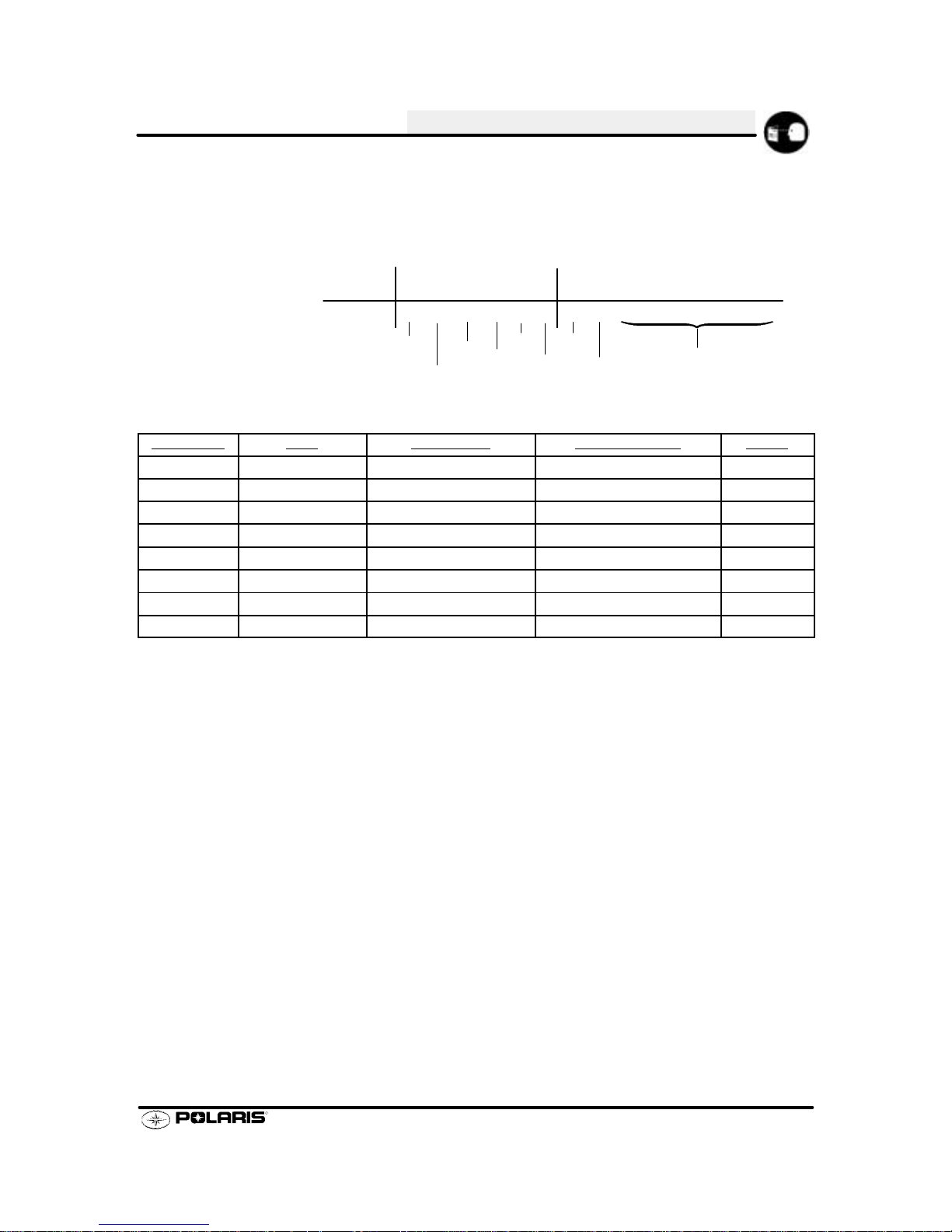
Vehicle Identification Number
Current snowmobiles havea 17 digit VehicleIdentification Number(VIN). TheVIN is organizedas follows: Digits
1-3: WorldManufacturerIdentifier. For Polaris, this is4XA. Digits 4-9: VehicleDescriptor Section. Digits 10-17:
Vehicle Indicator Section. Digits 4-8 of the VIN identify the body style, type, engine type, and series. The VIN
and the model number must be used with any correspondence regarding service or repair.
1 2 3 4 5 6 7 8 9 10 11 12 13 14 15 16 17
4XA SB
5BS022000000
Vehicle Descriptor
Vehicle Identifier
Type
Engine
Size
Engine
Modifier
Model
Year
Manufacturing.
Location Code
Individual Serial No.
Body Style
Series
World Mfg. ID
Example of
Current
VIN Number
Check
Digit
Vehicle Identification Number / Model Number Key
Body Style Type Engine Size Engine Modifier Series
L=Lite B=Base Model 1=100-199 cc A=Fan S=Domestic
N=Edge D=Deluxe 2=200-299 cc B=Liquid Twin U=Europe
S=Gen II P=Performance 3=300-399 cc C=Case Reed Twin
W=Mini R=RMK 4=400-499 cc D=Liquid Triple
S=SKS 5=500-599 cc E=Case Reed Triple
T=Touring 6=600-699 cc
U=Utility 7=700-799 cc
X=Racer 8=800-899 cc
Year / Letter Identification
The tenth digit of a 17 digit VIN is the model year of the vehicle. Example: W = 1998; X =1999 etc. Refer to the
listing below.
1 = 2001
2 = 2002
3 = 2003
Page 11
GENERAL INFORMATION
1.4
Standard Torque Specifications
Thefollowingtorquespecificationsaretobeusedasageneralguidelinewhentorquevalueisnotspecified. There
are exceptions in the steering, suspension, and engine areas. Always consult the torque chart and
the specific
manual section for torque values of fasteners.
Bolt Size Threads/In Grade 2 Grade 5 Grade 8
(MM/Thread)
Torque in. lbs. (Nm)
#10 - 24 27 (3.1) 43 (5) 60 (6.9).............. ................ ...............
#10 - 32 31 (3.6) 49 (5.6) 68 (7.8).............. ................ ..............
To rque ft. lbs. (Nm)*
1/4 - 20 5 (7) 8 (11) 12 (16).............. .................. ................
1/4 - 28 6 (8) 10 (14) 14 (19).............. .................. ..............
5/16 - 18 11 (15) 17(23) 25 (35).............. ................ ..............
5/16 - 24 12 (16) 19 (26) 29 (40).............. ................ ..............
3/8 - 16 20 (27) 30 (40) 45 (62).............. ................ ..............
3/8 - 24 23 (32) 35 (48) 50 (69).............. ................ ..............
7/16 - 14 30 (40) 50 (69) 70 (97).............. ................ ..............
7/16 - 20 35 (48) 55 (76) 80 (110).............. ................ ..............
1/2 - 13 50 (69) 75 (104) 110 (152).............. ................ .............
1/2 - 20 55 (76) 90 (124) 120 (166).............. ................ .............
*To convert ft. lbs. to Nm multiply foot pounds by 1.356.
*To convert Nm to ft. lbs. multply Nm by .7376.
Page 12

GENERAL INFORMATION
1.5
1/64 .0156.........................
1/32 .0312 1 mm = .0394²................... ................
3/64 .0469.........................
1/16 .0625..............
5/64 .0781 2 mm = .0787²......................... ................
3/32 .0938...................
7/64 .1094 3 mm = .1181²....................... ................
1/8 . .1250. .......
9/64 .1406.........................
5/32 .1563 4 mm = .1575²................... ................
11/64 .1719........................
3/16 .1875 5 mm = .1969².............. ................
13/64 .2031........................
7/32 .2188...................
15/64 .2344 6 mm = .2362²........................ ................
1/4 .25..........
17/64 .2656 7 mm = .2756²........................ ................
9/32 .2813...................
19/64 .2969........................
5/16 .3125 8 mm = .3150².............. ................
21/64 .3281........................
11/32 .3438 9 mm = .3543².................. ................
23/64 .3594........................
3/8 .375..........
25/64 .3906 10 mm = .3937²........................ ................
13/32 .4063..................
27/64 .4219 11 mm = .4331²........................ ................
7/16 .4375..............
29/64 .4531........................
15/32 .4688 12 mm = .4724².................. ................
31/64 .4844........................
1/2 .5 13 mm = .5118.......... ...................
33/64 .5156........................
17/32 .5313..................
35/64 .5469 14 mm = .5512²........................ ................
9/16 .5625..............
37/64 .5781 15 mm = .5906²........................ ................
19/32 .5938..................
39/64 .6094........................
5/8 .625 16mm = .6299².......... .................
41/64 .6406........................
21/32 .6563 17 mm = .6693².................. ................
43/64 .6719.......................
11/16 .6875.............
45/64 .7031 18 mm = .7087²........................ ................
23/32 .7188..................
47/64 .7344 19 mm = .7480²........................ ................
3/4 .75..........
49/64 .7656........................
25/32 .7813 20 mm = .7874².................. ................
51/64 .7969........................
13/16 .8125 21 mm = .8268²............. ................
53/64 .8281........................
27/32 .8438..................
55/64 .8594 22 mm = .8661²........................ ................
7/8 .875..........
57/64 .8906 23 mm = .9055²........................ ................
29/32 .9063..................
59/64 .9219.......................
15/16 .9375 24 mm = .9449²............. ................
61/64 .9531........................
31/32 .9688 25 mm = .9843.................. ................
63/64 .9844........................
Page 13
GENERAL INFORMATION
1.6
SAE Tap Drill Sizes
Thread Size Drill Size Thread Size Drill Size
#0-80 3/64
#1-64 53
#1-72 53
#2-56 51
#2-64 50
#3-48 5/64
#3-56 45
#4-40 43
#4-48 42
#5-40 38
#5-44 37
#6-32 36
#6-40 33
#8-32 29
#8-36 29
#10-24 24
#10-32 21
#12-24 17
#12-28 4.6mm
1/4-20 7
1/4-28 3
5/16-18 F
5/16-24 I
3/8-16 O
3/8-24 Q
7/16-14 U
7/16-20 25/64
1/2-13 27/64
1/2-20 29/64
9/16-12 31/64
9/16-18 33/64
5/8-11 17/32
5/8-18 37/64
3/4-10 21/32
3/4-16 11/16
7/8-9 49/64
7/8-14 13/16
1-8 7/8
1-12 59/64
1 1/8-7 63/64
1 1/8-12 1 3/64
11/4-7 17/64
1 1/4-12 1 11/64
11/2-6 111/32
1 1/2-12 1 27/64
13/4-5 19/16
1 3/4-12 1 43/64
2-4 1/2 1 25/32
2-12 1 59/64
2 1/4-4 1/2 2 1/32
21/2-4 21/4
23/4-4 21/2
3-4 2 3/4
Metric Tap Drill Sizes
Tap Size Drill Size Decimal Equivalent Nearest Fraction
3x.50
3x.60
4x.70
4x.75
5x.80
5x.90
6 x 1.00
7 x 1.00
8 x 1.00
8 x 1.25
9 x 1.00
9 x 1.25
10 x 1.25
10 x 1.50
11 x 1.50
12 x 1.50
12 x 1.75
#39
3/32
#30
1/8
#19
#20
#9
16/64
J
17/64
5/16
5/16
11/32
R
3/8
13/32
13/32
0.0995
0.0937
0.1285
0.125
0.166
0.161
0.196
0.234
0.277
0.265
0.3125
0.3125
0.3437
0.339
0.375
0.406
0.406
3/32
3/32
1/8
1/8
11/64
5/32
13/64
15/64
9/32
17/64
5/16
5/16
11/32
11/32
3/8
13/32
13/32
Page 14

GENERAL INFORMATION
1.7
Unit of Measure Multiplied by Converts to
ft. lbs. x12 =in.lbs.
in. lbs. x .0833 = ft. lbs.
ft. lbs. x 1.356 =Nm
in. lbs. x.0115 =kg-m
Nm x .7376 = ft. lbs.
kg-m x 7.233 = ft. lbs.
kg-m x86.796 =in.lbs.
kg-m x10 =Nm
in. x25.4 =mm
mm x .03937 =in.
in. x2.54 =cm
mile (mi.) x1.6 =km
km x .6214 = mile (mi.)
Ounces (oz) x28.35 = Grams (g)
Grams (g) x 0.035 = Ounces (oz)
cc x .03381 = Fluid Ounces (oz)
lb. x.454 =kg
kg x 2.2046 =lb.
Cubic inches (cu in) x16.387 = Cubic centimeters (cc)
Cubic centimeters (cc) x 0.061 = Cubic inches (cu in)
Imperial pints (Imp pt) x 0.568 = Liters (l)
Liters (l) x1.76 = Imperial pints (Imp pt)
Imperial quarts (Imp qt) x 1.137 = Liters (l)
Liters (l) x0.88 = Imperial quarts (Imp qt)
Imperial quarts (Imp qt) x 1.201 =USquarts(USqt)
US quarts (US qt) x 0.833 = Imperial quarts (Imp qt)
US quarts (US qt) x 0.946 = Liters (l)
Liters (l) x 1.057 =USquarts(USqt)
US gallons (US gal) x 3.785 =Liters (l)
Liters (l) x 0.264 = US gallons (US gal)
Pounds - force per square inch (psi) x 6.895 = Kilopascals (kPa)
Kilopascals (kPa) x 0.145 = Pounds - force per square inch (psi)
Kilopascals (kPa) x0.01 = Kilograms - force per square cm
Kilograms - force per square cm x98.1 = Kilopascals (kPa)
°Cto°F: 9 (°C + 40) ¸ 5--40=°F
°Fto°C: 5 (°F+40)¸ 9--40=°C
Page 15

GENERAL INFORMATION
1.8
Description Part Number
Chaincase Lubricant - Quart 2871280.......................
Chaincase Lubricant - Gallon 2870464......................
Chaincase Lubricant - 2.5 Gallon 2872281...................
Fuel System Deicer (Isopropyl) 2870505.....................
Loctite Primer T - 6 Oz. Aerosol 2870585....................
Loctite RC 680 - 10cc Retaining Compound 2870584..........
Loctite/Chisel -- Gasket Remover - 18 Oz. 2870601...........
Metal Polish - 8 Oz. 2870632...............................
DOT 3 Brake Fluid 2870990...............................
Fogging Oil 2870791......................................
Nyogelt Grease 2871329.................................
Fox Shock Oil 2870995....................................
Premium All Season Grease (14 oz) 2871423................
Premium All Season Grease (3 oz) 2871322.................
Premium 60/40 Anti-Freeze/Coolant 2871323................
Premium Carbon Clean Fuel System Additive 2871326........
Polaris Battery Tender 2871076............................
Carbon Clean Fuel System Additive 2871326.................
T-9 Metal Protectant 2871064..............................
Crankcase Sealant 3 Bond 1215 2871557...................
Page 16
GENERAL INFORMATION
1.9
ACS: Alternator control switch.
ACV: Alternating current voltage.
Air Gap Spark Test: Agoodcheckfor ignition voltage and general ignition system condition. Spark shouldarc 3/8” (1
cm) minimum from end of high tension lead to ground. Several testers are available commercially.
Alternator: Electrical generator producing alternating current voltage.
Bore: Diameter of cylinder.
BTDC: Before Top Dead Center.
Bump Steer: When skis toe in and toe out through suspension travel.
CDI: Capacitor Discharge Ignition. Ignition system which stores voltage generated by the stator plate exciter coil in a
capacitor or condenser (in CDI box). At thepropermomentavoltagegeneratedbythestatorplatepulsercoilclosesan
electronicswitch (thyristor) intheCDI boxandallows the voltage in the capacitor to discharge into the primary windings
of the ignition coil.
Center Cylinder: On three cylinder engines, the cylinder between Mag and PTO ends.
Center Distance: Distance between center of crankshaft and center of driven clutch shaft.
Chain Pitch: Distance between chain link pins (No. 35 = 3/8” or 1 cm). Polaris measures chain length in number of
pitches.
Clutch Buttons: Plastic bushings which transmit rotation of the clutch to the movable sheave in thedrive anddriven
clutch.
ClutchOffset: Driveanddrivenclutches are offsetsothat drive beltwillstay nearlystraightasit movesalongthe clutch
face as the engine torques back.
Clutch Weights: Threelevers in the drive clutchwhich relative to their weight,profileandengineRPMcausethedrive
clutch to close.
Coil: Awindingofwirearoundanironcorewhichhas the ability to generate an electricalcurrent whenamagneticfield
passes through it.
Combustion Chamber: Space between cylinder head and piston dome at TDC.
Compression: Reduction in volume or squeezing of a gas.
Condenser/Capacitor: A storage reservoir for electricity, used in both E.T. and CDI systems.
Crankshaft Run-Out: Run-out or “bend” of crankshaft measured with a dial indicator while crankshaft is supported
between centers on V blocks or resting in lower half of crankcase. Measure at various points especially at PTO.
Maximum allowable run-out is .006” (.02 cm).
DCV: Direct current voltage.
Detonation: The spontaneous ignition of the unburned fuel/air mixture after normal spark ignition. Piston looks
“hammered”through,rough appearance around hole. Possible causes: 1)leanfuel/air mixture; 2) low octane fuel; 3)
over-advanced ignition timing; 4)compression ratio too high for the fuel octane.
Dial Bore Gauge: A cylinder measuring instrument which uses a dial indicator. Good for showing taper and
out-of-round in the cylinder bore.
Displacement: The volume of the cylinder displaced by
the piston as it travelsfromBDC to TDC. The formula is:
Effective Compression Ratio: Compression ratio measured from after the piston closes the exhaust port.
Electrical Open: Open circuit. An electrical circuit whichisn’t complete. (i.e.poor connections or brokenwire at hi-lo
beam switch resulting in loss of headlights.
Electrical Short: Short circuit. An electrical circuit which is completed before the current reaches the intended
component. (i.e. a bare wire touching the snowmobile chassis under the seat resulting in loss of taillights and brake
lights).
End Seals: Rubber seals at each end of the crankshaft.
Engagement RPM: Engine RPM at which the drive clutch engages to make contact with the drive belt.
Flat Head Bolt: To be used where finished surfaces require a flush fastening unit. Countersunk.
Foot Pound: Ft. lb. A force of one pound at the end of a lever one foot in length, applied in a rotational direction.
g: Gram. Unit of weight in the metric system.
Head V o lume: Cylinder head capacity in cc, head removed from engine with spark plug installed.
4
Bore x Stroke x 3.1416
2
= Displacement in
CCs
Page 17

GENERAL INFORMATION
1.10
Heat Exchanger: A device used to transfer heat. They dissipate engine heat to the atmosphere.
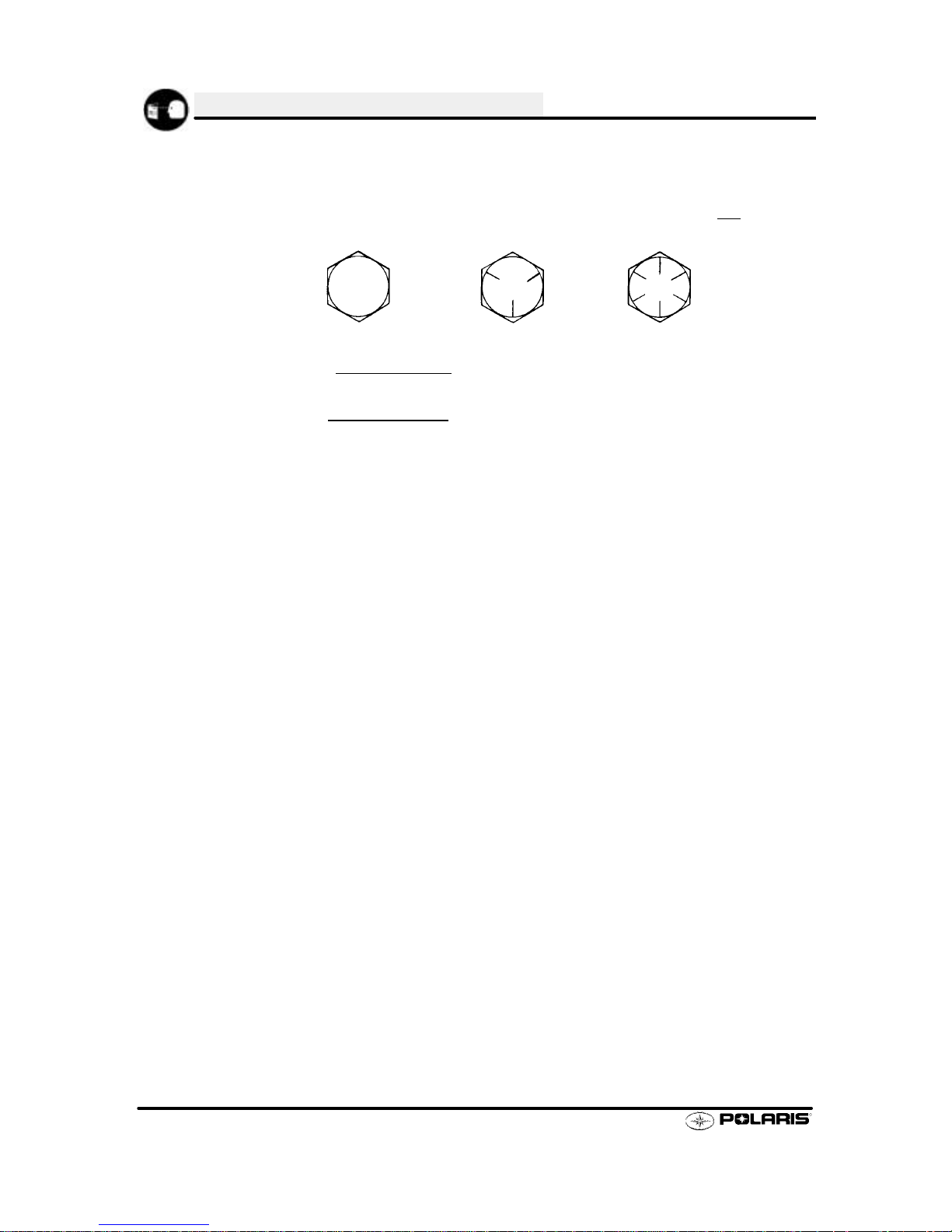
HexHead Bolt: Standardtypeofwrench-appliedhexagonhead,characterized by clean, sharp corners trimmed
to close tolerances. Recommended for general commercial applications.
Hi-Fax: Trademark of Himont Advanced Materials. The special slide material which fits onto the bottom of the
suspension rails.
High Side: Sled pushes or tips up toward outside of turn.
High TensionWire: Theheavy insulated wire which carries the high secondaryvoltagefromthecoil tothesparkplug.
Hole Shot: A term used when machine starts a race from a dead stop.
Holed Piston: Piston in which a hole has formed on the dome. Possible causes: 1) detonation; 2) pre-ignition.
IgnitionCoil: A typeoftransformerwhichincreasesvoltage in the primary windings (approx. 200V) to a higher voltage
in the secondary windings (approx. 14KV -32KV) through inductions. Secondary voltage is high enough toarc the air
gap at the spark plug.
IgnitionGenerating Coil: Excitercoilorprimary charge coil. Statorplatecoilwhichgeneratesprimary ignitionvoltage.
CDI system uses one ignition generating coil.
Inch Pound: In. lb. 12 in. lbs. = 1 ft. lb.
Kg/cm2: Kilograms per square centimeter. Metric equivalent of PSI.
Keystone Ring: A piston ring with bevel on upper surface.
Kilogram/meter: A force of one kilogram at the end of a lever one meter in length, applied in a rotational direction.
Metric equivalent of ft. lbs.
LRing: A wide face piston ring with an ”L” shaped cross section. Leg of ”L” goes up when installing on piston.
Labyrinth Seal: A pressure typecenter seal identified by series of grooves and lands. Polarisengines us this type of
seal to separate the cylinders in the crankcase halves.
Left Side: Always referred to based on normal operating position of the driver.
Lighting Coil: Generates voltage for lights, battery charging, etc by electromagnetic induction.
Loose: When the rear of the vehicle slides outward in a turn. The track does not grab sufficiently.
mm: Millimeter. Unit of length in the metric system. 1mm = .040”.
Mag End: Flywheel side of engine.
Magnetic Induction: As a conductor (coil) is moved through a magnetic field, a voltage will be generated in the
windings. This is how mechanical energy in our engines is converted to electrical energy in the lighting coil, ignition
generating coils and trigger coil.
Ohm: The measurement of electrical resistance opposing current flow.
Oval Head Screw: Fully specified as ”oval countersunk”, this head is identical to the standard flat head, but
possesses a rounded upper surface for attractiveness of design.
PTO End: Power Take Off drive (clutch side).
Pan Head Screw: Provides a low, large diameter head, but with characteristically high outer edges along the
outeredgeof the headwheredrivingaction is mosteffective. Slightly differentheadcontourwhensupplied with Phillips
Recess. See dotted line.
Piston Clearance: Total distance between piston and cylinder wall.
PistonErosion: Pistondomemelts. Usuallyoccursat theexhaustportarea. Possible causes: 1) leanfuel/airmixture;
2) improper spark plug heat range; 3) Poor fuel.
Pre-Ignition: A problem in combustion where the fuel/air mixture is ignited beforenormal spark ignition. Piston looks
melted at area of damage. Possible causes: 1)incorrect spark plug heatrange; 2) spark plug notproperly torqued; 3)
“glowing” piece of head gasket, metal burr or carbon in the combustion chamber; 4) lean fuel/air mixture; 5) Incorrect
ignition timing.
Primary Circuit: Thiscircuitisresponsibleforthe voltagebuildupinthe primarywindingsofthe coil. Inthe CDIsystem
thepartsinclude the exciter coil,the trigger coil, the wiresfromstatorplatetoCDIboxandtothelowresistanceprimary
windings in the ignition coil.
Primary Clutch: Drive clutch on engine.
Primary Compression: Pressure built up in the crankcase of a two stroke engine.
Page 18

GENERAL INFORMATION
1.1 1
psi.: Pounds per square inch.
Pushing: Whenthe front of the vehicle does not steeras much as the driverdesires. The skis donot grab sufficiently.
R&R: Remove and replace.
RFI: RadioFrequencyInterference. Caused by high voltage from the ignition system. Therearespecialplugcapsand
spark plugs to help eliminate this problem. Mandated in Canada.
RPM: Revolutions Per Minute.
Resistance: Inthe mechanicalsense,frictionor load. Intheelectricalsense,ohms. Bothresultinenergy conversionto
heat.
Right Side: Always referred to based on normal operating position of the driver.
Round Head Screw:The familiar head most universally used for general application. Good slot depth, ample
underhead bearing surface and finished appearance are characteristic of this head.
Running Time: Ignition timing at specified RPM.
Secondary Circuit: Thiscircuitconsists ofthelargesecondarycoilwindings,hightensionwire andgroundthroughthe
spark plug air gap.
Secondary Clutch: Driven clutch on chaincase or jackshaft.
SeizedPiston: Gallingof the sidesofapiston. Usually there is atransferofaluminumfromthe piston onto the cylinder
wall. Possible causes: 1) improper lubrication; 2) excessive temperatures; 3) insufficient piston clearance; 4)stuck
piston rings.
Self Steer: Pulling the machine to the inside of the track.
Spark Plug Reach: Length of threaded portion of spark plug. Polaris uses 3/4” (2 cm) reach plugs.
Static Timing: Ignition timing when engine is at zero RPM.
Stator Plate: The plate mounted under the flywheel supporting the primary ignition components and lighting coils.
Stroke: Themaximum movement of the piston from bottom deadcentertotop deadcenter. Itischaracterizedby180°
of crankshaft rotation.
Surge Tank: The fill tank in the liquid cooling system.
TDC: Top Dead Center. Piston’s most outward travel from crankshaft.
Transfer: The movement of fuel/air from the crankcase to the combustion chamber in a two stroke engine.
Trigger Coil: Pulser coil. Generates the voltage for triggering (closing) the thyristor and timing the spark in CDI
systems. Small coil mounted at the top of the stator plate next to the ignition generating coil, or on the outside of the
flywheel.
V Regulator: Voltage regulator. Maintains maximum lighting coil output at approx. 14.5 ACV as engine RPM
increases.
Venturi: Anareaofairconstriction. Aventuriisusedincarburetors tospeedupair flowwhichlowerspressureinventuri
tobelowatmosphericpressure,causingfuelto be pushedthroughjets,etc.,andintotheventuri to be mixed with air and
form a combustible air/fuel mixture.
Volt: The unit of measure for electrical pressure of electromotive force. Measured by a voltmeter in parallel with the
circuit.
Watt: Unit of electrical power. Watts = amperes x volts.
Page 19

GENERAL INFORMATION
1.12
In order to perform service work efficiently and toprevent costly errors, the technician should read the text in this
manual, thoroughly familiarizing him/herself with procedures before beginning. Photographs and illustrations
havebeenincluded with the text as an aid. Notes,cautions and warningshave also been included forclarification
of text and safety concerns. However, a knowledge of mechanical theory, tool use and shop procedures is
necessary to perform the service work safely and satisfactorily. Use only genuine Polaris service parts.
Cleanlinessofpartsandtoolsaswellastheworkareaisof primaryimportance. Dirtandforeignmatter will act
asanabrasiveandcausedamagetoprecisionparts. Cleanthesnowmobile before beginning service. Cleannew
parts before installing.
Watch for sharp edges which can cause personal injury, particularly in the area of the tunnel. Protect hands
with gloves when working with sharp components.
If difficulty is encountered in removingor installing acomponent, look tosee if acausefor thedifficulty canbe
found. If it is necessary to tap the part into place, use a soft face hammer and tap lightly.
Some of the fasteners in the snowmobile were installed with locking agents. Use of impact drivers or
wrenches will help avoid damage to fasteners.
Alwaysfollowtorquespecifications as outlined throughout thismanual. Incorrect torquing may leadtoserious
machine damage or, as in the case of steering components, can result in injury or death for the rider(s).
If a torquing sequence isindicated for nuts, bolts or screws, start all fasteners in their holes and handtighten.
Then, following the method and sequence indicated in this manual, tighten evenly to the specified torque value.
When removing nuts, bolts or screws from a part with several fasteners, loosen them all about 1/4 turn before
removing them.
If the condition ofany gasket or O-Ring is inquestion, replaceit witha new one. Besure the matingsurfaces
around the gasket are clean and smooth in order to avoid leaks.
Some procedures will require removal of retaining rings or clips. Because removal weakens and deforms
theseparts, they should always bereplacedwithnewparts. Wheninstallingnewretainingringsandclipsusecare
not to expand or compress them beyond what is required for installation.
Because removal damages seals, replace any oil or grease seals removed with new parts.
Polaris recommends the use of Polaris lubricants and greases, which have beenspecially formulated for the
top performance and best protection of our machines. In some applications, such as the engine, warranty
coverage may become void if other brands are substituted.
Grease should be cleaned from parts and fresh grease applied before reassembly of components.
Deteriorating grease loses lubricity and may contain abrasive foreign matter.
Whenever removing or reinstalling batteries, care should be taken to avoid the possibility of explosion
resulting in serious burns. Always disconnect the negative (black) cable first and reconnect it last. Battery
electrolyte contains sulphuric acid and is poisonous! Serious burns can result from contact with the skin, eyes or
clothing. ANTIDOTE: External - Flush with water. Internal - Drink large quantities or water or milk. Follow with
milkofmagnesia,beatenegg,orvegetableoil. Call physician immediately. Eyes - Flushwithwaterfor 15minutes
and get prompt medical attention.
Page 20

GENERAL INFORMATION
1.13
Notes
Page 21
GENERAL INFORMATION
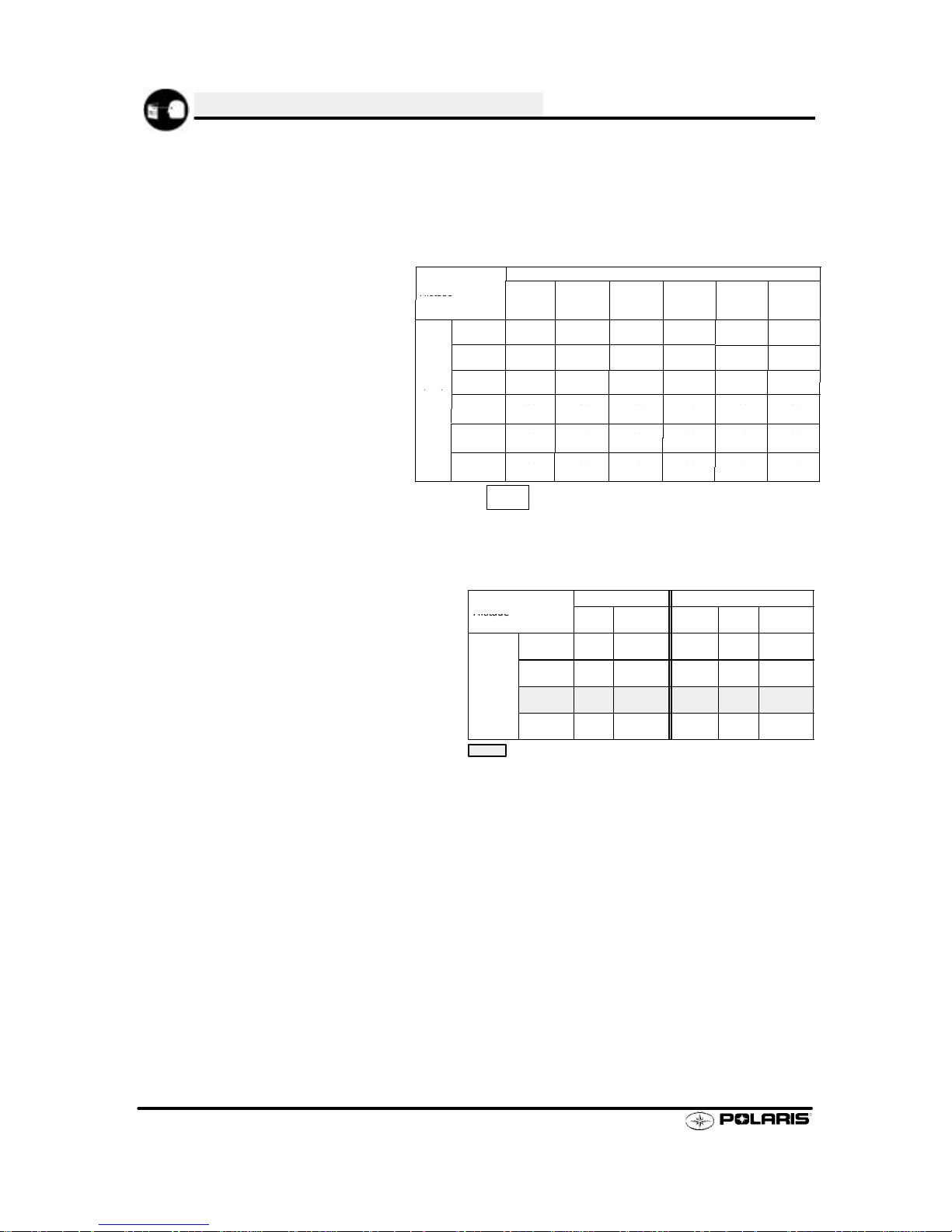
1.14
MODEL: INDY 500 SKS EUROPEAN..........
MODEL NUMBER: E02SS5AE.
ENGINE MODEL: S2209--5044PL5A..
JETTING CHART
AMBIENT TEMPERATURE
Altitude
Below -30°F
Below -34°C
-30
_ to --10_F
-34_to -23_C
-- 1 0
_to +10_F
-23_ to --12_C
+10
_to +30_F
-12_to --1_C
+30
_to +50_F
-1_to +10_C
Above +50
_F
Above +10_C
Altitud
e
Below34
C
-
34t
o-23C
-
23t
o--12C
-
12t
o--1
C
-
1to+10CAbove+10
C
0--600
(0--2000)
390
#3
380
#3
360
#3
350
#3
330
#3
320
#3
600--1200
(2000--4000)
370
#3
360
#3
340
#3
330
#3
310
#3
300
#2
Meters
1200--1800
350
330
320
300
290
280
Meter
s
(Feet)
1200180
0
(4000--6000)
350
#3
330
#3
320
#3
300
#3
290
#2
280
#2
(
)
1800--2400
330
310
300
290
370
250
(6000--8000)
330
#3
3
0
#3
300
#3
9
0
#2
3
0
#2
5
0
#2
2400--3000
300
290
280
260
250
230
(8000--10000)
300
#3
9
0
#3
8
0
#2
6
0
#2
5
0
#2
3
0
#1
3000--3700
280
270
250
240
220
210
(10000--12000)
8
0
#3
0
#2
5
0
#2
0
#2
0
#2
0
#2
XXX
#X
- # refers to the clip position from top of jet needle.
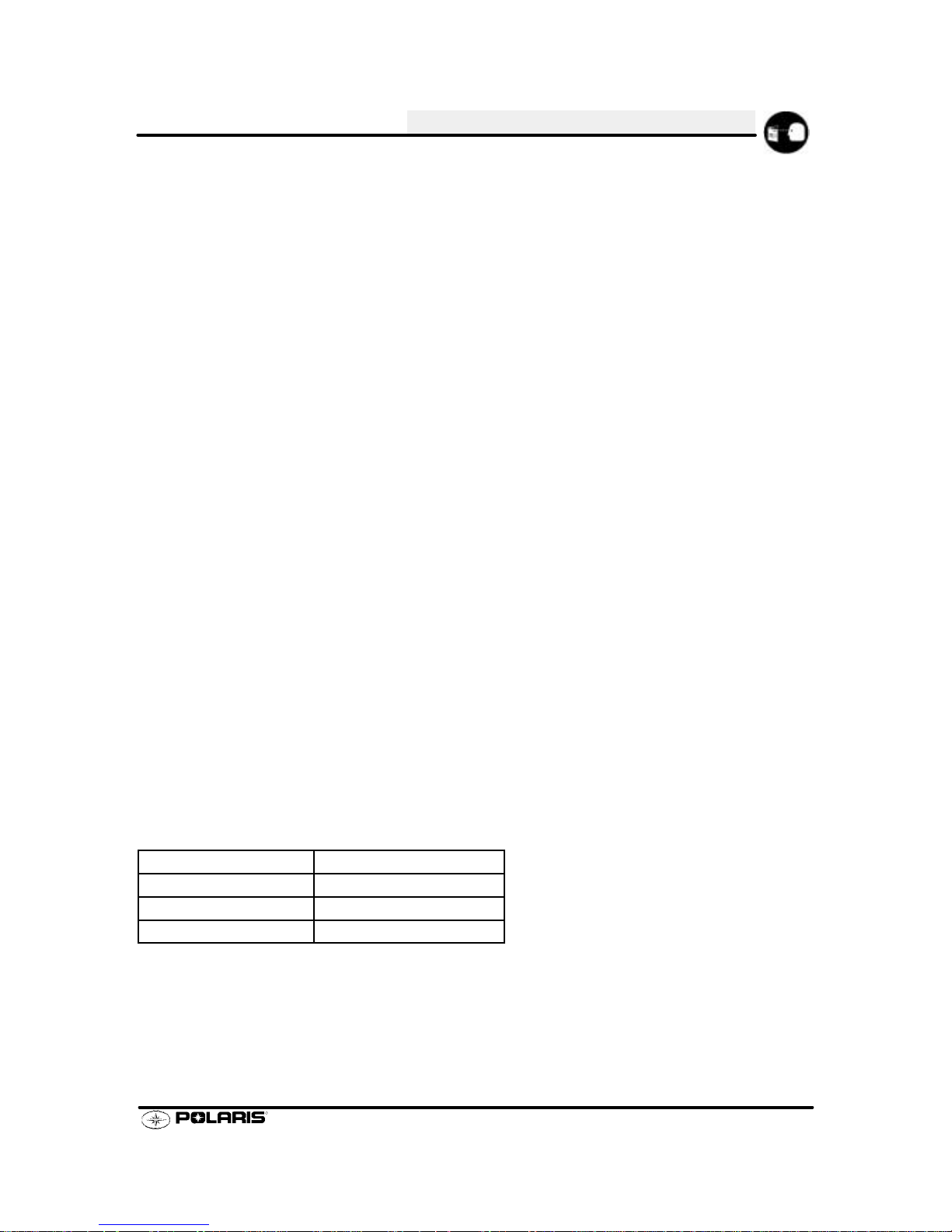
CLUTCH CHART
DRIVE DRIVEN
Altitude
Shift Clutch Clutch Driven
Chaincase
Altitud
e
Shift
Weight
Clutc
h
Spring
Clutc
h
Spring
Drive
n
Helix
Chaincase
Gearing
Meters
0-900
1
-
D
rk Bl
R
2
18-41-68P
Meter
s
(Feet)
0-900
(0-3000)
1
0-5
6
Bushed
DarkBlue/
White
Silver
R32
#2
1
8-4
1-68P
HYVO
900-1800
1-L
lm
n
R
2
18-41-68P
900-180
0
(3000-6000)
1
0-A
L
Bushed
Almond/
Round
Silver
R32
#2
1
8-4
1-68P
HYVO
1800-2700
1
lm
n
R
2
18-41-68P
180
0-270
0
(6000-9000)
1
0
Bushed
Almond/
Round
Silver
R32
#2
1
8-4
1-68P
HYVO
2700-3700
10M
5
Almond
/R3
2
18-41-68P
270
0-370
0
(9000-12000)
10M
5
Bushed
Almond/
Round
Silver
R32
#2
1
8-4
1-68P
HYVO
- Production Setting
ENGINE
Type Liquid Cooled Case Reed Twin.......................
Displacement 500cc Fuel Pump Manuf. N/A............... .....
Bore 2.776²² (70.5mm) Fuel Pump Mark N/A....................... .......
Stroke 2.520²² (64mm) Oil Pump Manuf. Mikuni..................... .......
Piston / Cylinder Clearance 0.0045² - 0.0063² (0.11 - 0.16mm) Oil Pump Mark 2540051... ........
Service Limit N/A Cylinder Head Mark 3021048................ ....
Piston Marking 3021038..............
Piston Ring Marking N/A.........
Piston Ring End Gap 0.012² -0.018² (.30 - .46mm)........
Head ccs (Uninstalled) 27.5±.50cc.......
Head ccs (Installed) 25cc.........
Operating RPM±200 8000 RPM.........
Idle RPM±200 1500 RPM..............
Engagement RPM±300 4200 RPM......
Cylinder Head Torque 20-24 ft.lbs. (28-33Nm)........
Cylinder Base Nut Torque 30-34 ft.lbs. (41-47 Nm)....
Crankcase Torque (8mm) 20-24ft.lbs. (28-33 Nm).....
Crankcase Torque (10mm) N/A...
Flywheel Torque 90ft.lbs. (124 Nm).............
CARBURETION
Type TM 38 Mikuni................
Main Jet 370............
Pilot Jet 45.............
Jet Needle 9FH4--57/3...........
Needle Jet P-6...........
Cutaway 1.5............
Fuel Mixture Screw 2 Turns...
Valve Seat 1.5...........
Fuel Octane (R+M/2) 87 Non-Oxygenat
ed
.
89 Oxygenated
ThrottleGap
Under Cutaway 0.098² (2.5mm)......
Starter Jet 155...........
Pilot Air Jet 1.0..........
CLUTCH
Type P 85................
Belt 3211074.................
Belt Width (Projected) 1.438².
Side Angle (Overall) 28°..
Outside Circumference 47.625²
Center Distance 12.00²......
Shift Weights 10-56 Bushed........
Primary Spring Dark Blue / White.......
Secondary Spring Silver....
Driven Helix R32 #2.........
Page 22
GENERAL INFORMATION
1.15
MODEL: INDY 500 SKS EUROPEAN..........
MODEL NUMBER: E02SS5AE.
ENGINE MODEL: S2209--5044PL5A..
ELECTRICAL CAPACITIES
Flywheel I.D. 4010523 Fuel Tank 11.8 gallons (44.7 liters)...... ..........
CDI Marking 4010584 Oil Tank 3 quarts (2.8 liters)....... ............
Alternator Output 280 Watts Coolant 5 quarts (4.7 liters)... ............
Ignition Timing 12° BTDC@22500 RPM Chaincase Oil 11 fl. oz. (325cc)..... .......
0.0327² BTDC
0.8294mm BTDC
Spark Plug / Gap Champion RN2C / 0.028² (0.7mm)...
Voltage Regulator LR7..
Electric Start Option.......
LR7= Full wave voltage regulator
Magneto Pulses 6....
SUSPENSION / CHASSIS CHAINCASE
Body Style Gen II Sprockets / Chain 18-41, 68P HYVO........ ...
Front Suspension Indy XC 10 Reverse Option.. ............
Front Shocks Indy Select Brake Pads Type 81, Large...... .........
IFS Spring Rate 100#/in. Chaincase Center Dist.7.05² (17.91cm)....
Front Spring Preload 3/4² Thread Adjust Driveshaft Sprockets 2 Drivers Wide.
Front Vertical Travel 9.6² (24.4cm) Brake Type Polaris HPB.........
Rear Suspension XTRA-10 EURO...
Rear Axle Travel 9.5² (24.1cc)...
Front Track Shock Nitrogen Cell..
Spring Rate 190#/in. variable........
Rear Track Shock Indy Select..
Rear Springs .405² (sq.) / 77°......
Track Type 15²x136²x1.25² (38.1x345.44x3.175cm)........
Track Tension 3/8² -1/2² (1-1.3 cm) slack with 10# (4.54kg) weight 16² (40.64cm) ahead of rear idler......
shaft.
Overall Snowmobile Length 116² (295cm).................
Overall Snowmobile Height 45² (114cm).................
Maximum Snowmobile Width 43.5² (110.5cm)...............
OPTIONAL REAR TORSION SPRINGS
(STD)
.405²(Sq.) Diameter x 77°
L.H. 7041655--067
R.H 7041655--067
Page 23
GENERAL INFORMATION
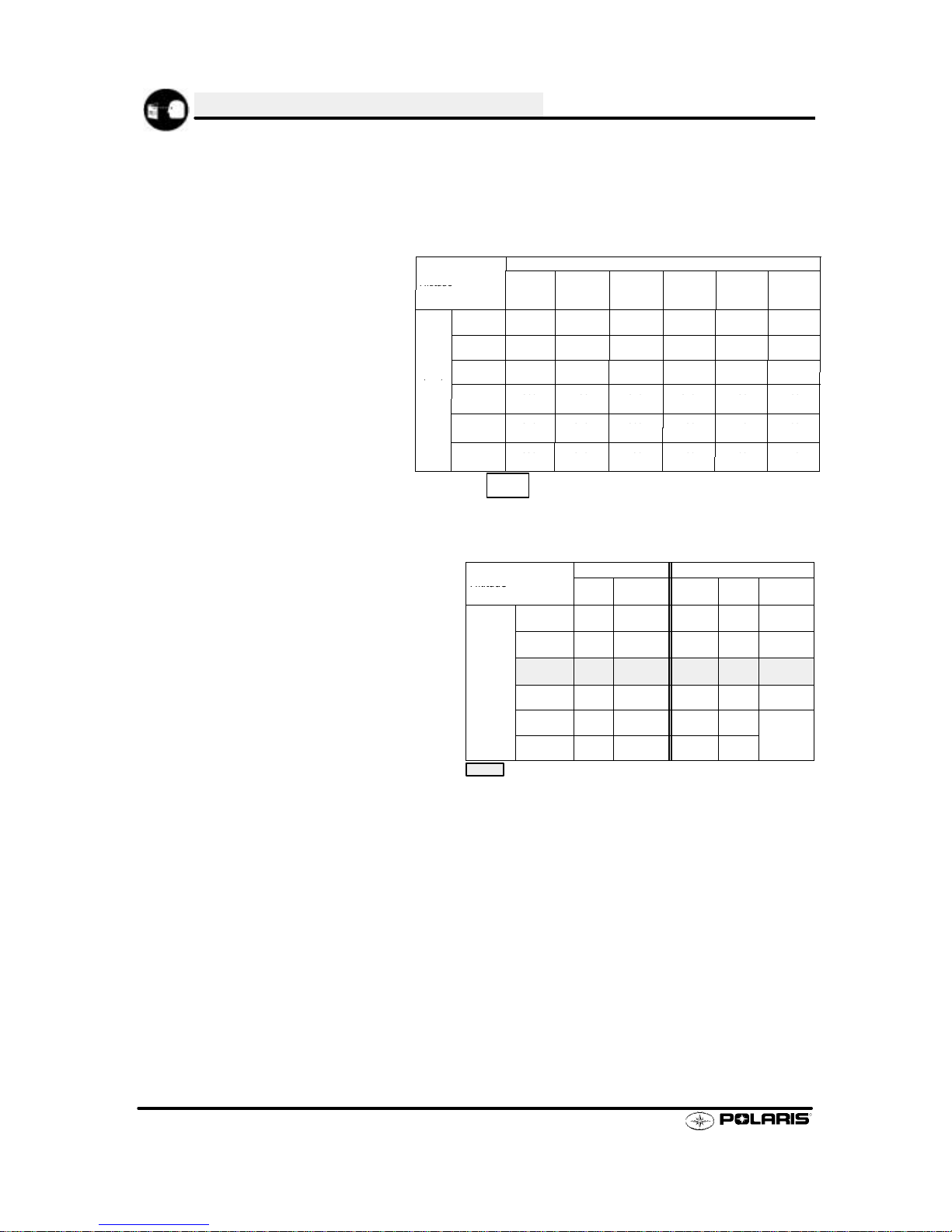
1.16
MODEL: INDY 500 RMK..........
MODEL NUMBER: S02SR5AS.
ENGINE MODEL: S2186--5044PL5A..
JETTING CHART
AMBIENT TEMPERATURE
Altitude
Below -30°F
Below -34°C
-30
_ to --10_F
-34_to -23_C
-- 1 0
_to +10_F
-23_ to --12_C
+10
_to +30_F
-12_to --1_C
+30
_to +50_F
-1_to +10_C
Above +50
_F
Above +10_C
Altitud
e
Below34
C
-
34t
o-23C
-
23t
o--12C
-
12t
o--1
C
-
1to+10CAbove+10
C
0--600
(0--2000)
440
#3
420
#3
410
#3
390
#3
380
#3
370
#3
600--1200
(2000--4000)
390
#3
380
#3
370
#3
350
#3
340
#2
320
#2
Meters
1200--1800
350
330
320
310
300
290
Meter
s
(Feet)
1200180
0
(4000--6000)
350
#2
330
#2
320
#2
310
#2
300
#2
290
#2
(
)
1800--2400
300
290
280
270
260
250
(6000--8000)
300
#2
9
0
#2
8
0
#2
0
#2
6
0
#2
5
0
#2
2400--3000
280
270
260
250
240
230
(8000--10000)
8
0
#2
0
#2
6
0
#2
5
0
#2
0
#2
3
0
#2
3000--3700
260
250
240
230
220
210
(10000--12000)
6
0
#2
5
0
#2
0
#2
3
0
#2
0
#2
0
#2
XXX
#X
- # refers to the clip position from top of jet needle.
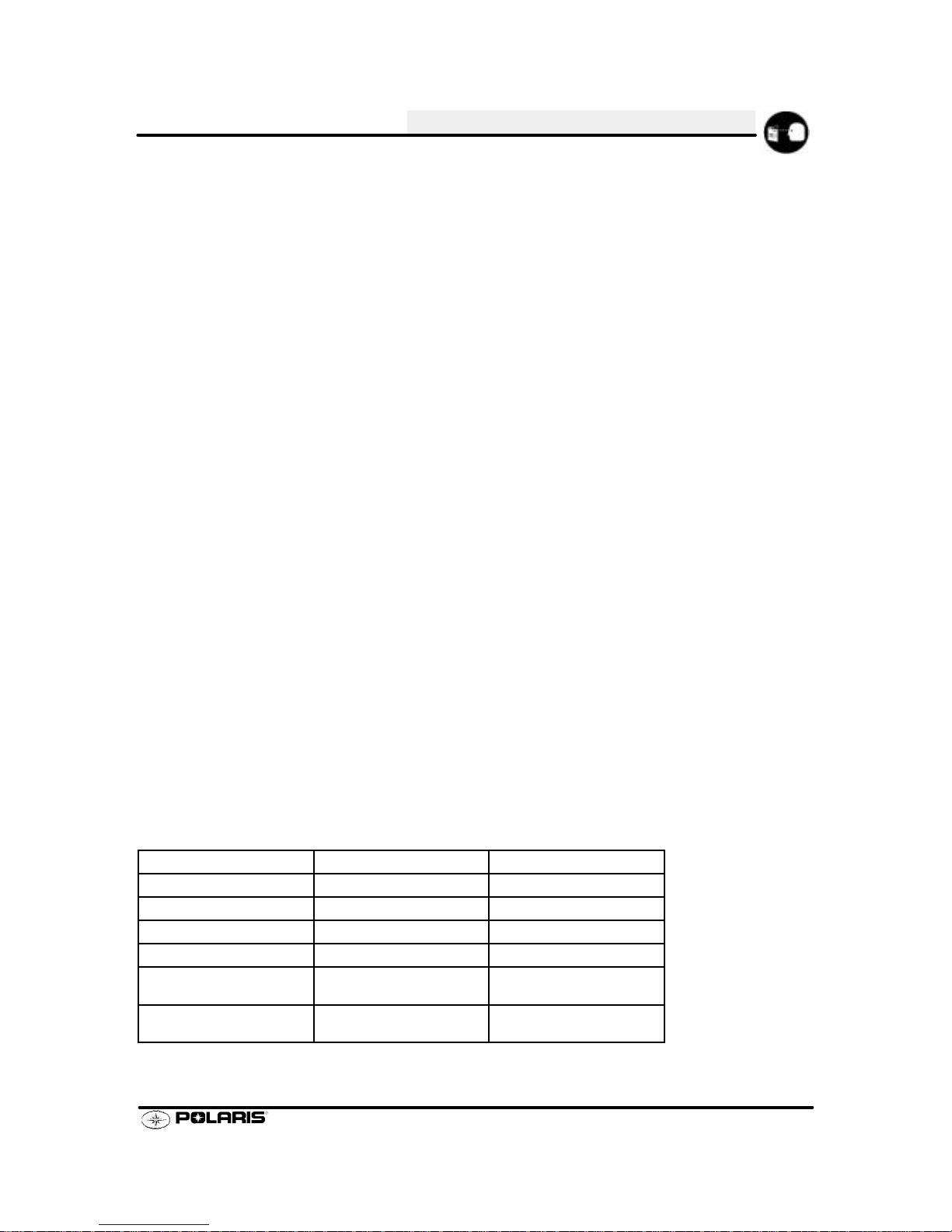
CLUTCH CHART
DRIVE DRIVEN
Altitude
Shift Clutch Clutch Driven
Chaincase
Altitud
e
Shift
Weight
Clutc
h
Spring
Clutc
h
Spring
Drive
n
Helix
Chaincase
Gearing
Meters
0-900
10-
56Almond
S
ilver/R-32
18-41-68P
Meter
s
(Feet)
0-900
(0-3000)
1
0-5
6
Bushed
Almon
d
Round
Silver/
Blue
R-3
2
#3
1
8-4
1-68P
HYVO
900-1800
10-ALAlmon
d
S
ilver/R-32
18-41-68P
900-180
0
(3000-6000)
1
0-A
L
Bushed
Almon
d
Round
Silver/
Blue
R-3
2
#3
1
8-4
1-68P
HYVO
1800-2700
1
0
Almond
S
ilver/R-32
18-41-68P
180
0-270
0
(6000-9000)
1
0
Bushed
Almon
d
Round
Silver/
Blue
R-3
2
#3
1
8-4
1-68P
HYVO
2700-3700
1
M
lm
n
ilv
r
R-
2
18-41-68P
270
0-370
0
(9000-12000)
10M
Bushed
Almon
d
Round
Silver/
Blue
R-3
2
#3
1
8-4
1-68P
HYVO
- Production Setting
ENGINE
Type Liquid Cooled Case Reed Twin.......................
Displacement 500cc Fuel Pump Manuf. Walbro............... .....
Bore 2.776² (70.5mm) Fuel Pump Mark FPA-3....................... .......
Stroke 2.520² (64mm) Oil Pump Manuf. Mikuni..................... .......
Piston / Cylinder Clearance 0.0045² -0.0063² (0.11 - 0.16mm) Oil Pump Mark 2540051... ........
Service Limit 0.0063” (0.16mm) Cylinder Head Mark 3021048................ ....
Piston Marking N/A..............
Piston Ring Marking N/A.........
Piston Ring End Gap 0.012² -0.018² (0.30 - 0.46mm)........
Head ccs (Uninstalled) 27.5±0.5cc.......
Head ccs (Installed) 25.0cc.........
Operating RPM±200 8000 RPM.........
Idle RPM±200 1500 RPM..............
Engagement RPM±300 4500 RPM......
Cylinder Head Torque 20-24 ft.lbs. (28-33Nm)........
Cylinder Base Nut Torque 30-34 ft.lbs. (41-47 Nm)....
Crankcase Torque (8mm) 20-24ft.lbs. (28-33 Nm).....
Crankcase Torque (10mm) N/A...
Flywheel Torque 90ft.lbs. (124 Nm).............
CARBURETION
Type TM38 Mikuni................
Main Jet 270............
Pilot Jet 45.............
Jet Needle 9FH4-57-2...........
Needle Jet P-6...........
Cutaway 1.5 Notched............
Fuel Screw 0.5 Turns..........
Valve Seat 1.5 Viton...........
Fuel Octane (R+M/2) 87 Non-Oxygenated.
89 Oxygenated
ThrottleGap
Under Cutaway 0.130² (3.3mm)......
Starter Jet 155...........
Pilot Air Jet 0.7 Long..........
CLUTCH
Type P-85................
Belt 3211074.................
Belt Width (Projected) 1.438² (36.52mm).
Side Angle (Overall) 28°..
Outside Circumference 47.625² (121cm)
Center Distance 12.00²......
Shift Weights 10 Bushed........
Primary Spring Almond Round.......
Secondary Spring Silver / Blue....
Driven Helix R-32 #3.........
Page 24
GENERAL INFORMATION
1.17
MODEL: INDY 500 RMK..........
MODEL NUMBER: S02SR5AS.
ENGINE MODEL: S2186--5044PL5A..
ELECTRICAL CAPACITIES
Flywheel I.D. Kokusan 4060223 Fuel Tank 11.8 gallons (44.7 liters)...... ..........
CDI Marking 4010259 Oil Tank 3 quarts (2.8 liters)....... ............
Alternator Output 280 Watts Coolant 5 quarts (4.7 liters)... ............
Ignition Timing 22° BTDC@3000RPM±1.5° Chaincase Oil 9 fl. oz.(266cc)..... .......
0.1139² BTDC (±0.0175²)
2.8927mm BTDC (±0.48mm)
Spark Plug / Gap Champion RN2C / 0.025² (0.64mm)...
Voltage Regulator LR7..
Electric Start Option.......
LR7= Full wave voltage regulator
Magneto Pulses 6....
SUSPENSION / CHASSIS CHAINCASE
Body Style Gen II Sprockets / Chain 18-41, 68P HYVO........ ...
Front Suspension Indy X-10 38² CRC Reverse Option.. ............
Front Shocks Nitrogen Cell Brake Pads Type 81, Large...... .........
IFS Spring Rate 100#/in. Chaincase Center Dist.7.05² (17.91cm)....
Front Spring Preload 1/8² Thread Adjust Driveshaft Sprockets 2 Drivers Wide.
Front Vertical Travel 8.05 in.(21cm) Brake Type Polaris HPB.........
Rear Suspension XTRA-Lite 136²...
Rear Axle Travel 12² (30.5cm)...
Front Track Shock Nitrogen Cell..
Spring Rate 200#/in. variable........
Rear Track Shock Indy Select..
Rear Springs .347² (sq.) / 77°......
Track Type 15²x136²x1.5² (38.1x345.44x3.81cm)........
Track Tension 3/8² -1/2² (1-1.3 cm) slack with 10# (4.54kg) weight 16² (40.64cm) ahead of rear idler......
shaft.
Overall Snowmobile Length 116² (295cm).................
Overall Snowmobile Height 45² (114cm).................
Maximum Snowmobile Width 43.5² (110.4cm)...............
OPTIONAL REAR TORSION SPRINGS
(STD) FIRM
.347²(Sq.) Diameter x 77° .375” (Sq.) Diameter x 77____
L.H. 7041627--067 L.H. 7041631--067
R.H 7041628--067 R.H. 7041632--067
Page 25

GENERAL INFORMATION
1.18
MODEL: INDY TRAIL RMK..........
MODEL NUMBER: S02SR5BS.
ENGINE MODEL: EC55PM024..
JETTING CHART
AMBIENT TEMPERATURE
Altitude
Below -30°F
Below -34°C
-30
_ to --10_F
-34_to -23_C
-- 1 0
_to +10_F
-23_ to --12_C
+10
_to +30_F
-12_to --1_C
+30
_to +50_F
-1_to +10_C
Above +50
_F
Above +10_C
Altitud
e
Below34
C
-
34t
o-23C
-
23t
o--12C
-
12t
o--1
C
-
1to+10CAbove+10
C
0--600
(0--2000)
300
#3
290
#3
280
#3
270
#3
260
#3
250
#3
600--1200
(2000--4000)
300
#3
290
#3
280
#3
270
#3
260
#3
250
#3
Meters
1200--1800
300
290
280
270
260
250
Meter
s
(Feet)
1200180
0
(4000--6000)
300
#3
290
#3
280
#3
270
#3
260
#3
250
#3
(
)
1800--2400
300
290
280
270
260
250
(6000--8000)
300
#3
9
0
#3
8
0
#3
0
#3
6
0
#3
5
0
#3
2400--3000
300
290
280
270
260
250
(8000--10000)
300
#3
9
0
#3
8
0
#3
0
#3
6
0
#3
5
0
#3
3000--3700
300
290
280
270
260
250
(10000--12000)
300
#3
9
0
#3
8
0
#3
0
#3
6
0
#3
5
0
#3
XXX
#X
- # refers to the clip position from top of jet needle.
CLUTCH CHART
DRIVE DRIVEN
Altitude
Shift Clutch Clutch Driven
Chaincase
Altitud
e
Shift
Weight
Clutc
h
Spring
Clutc
h
Spring
Drive
n
Helix
Chaincase
Gearing
Meters
0-900
10-62 Dark Bl
ue/
S
ilver/R-32
18-41-68P
Meter
s
(Feet)
0-900
(0-3000)
1
0-6
2
Bushed
DarkBlue/
White
Silver/
Blue
R-3
2
#2
1
8-4
1-68P
HYVO
900-1800
10-
5
8Da
rk Bl
ue/
S
ilver/R-32
18-41-68P
900-180
0
(3000-6000)
1
0-5
8
Bushed
DarkBlue/
White
Silver/
Blue
R-3
2
#2
1
8-4
1-68P
HYVO
1800-2700
10-
5
6Da
rk Bl
ue/
S
ilver/R-32
18-41-68P
180
0-270
0
(6000-9000)
1
0-5
6
Bushed
DarkBlue/
White
Silver/
Blue
R-3
2
#2
1
8-4
1-68P
HYVO
2700-3700
1-4 D
rk Bl
ilv
r
R-
2
18-41-68H
270
0-370
0
(9000-12000)
1
0-5
4
Bushed
DarkBlue/
White
Silver/
Blue
R-3
2
#2
1
8-4
1-68H
YVO
- Production Setting
ENGINE
Type Fan Cooled Reed Assist Twin.......................
Displacement 544cc Fuel Pump Manuf. T aiyo............... .....
Bore 2.874² (73mm) FuelPump Mark FJP-3-100....................... .......
Stroke 2.559² (65mm) Oil Pump Manuf. Mikuni..................... .......
Piston / Cylinder Clearance 0.0035² -0.0049² (0.09 - 0.125mm) Oil Pump Mark 55MB... ........
Service Limit 0.0078² (0.20mm) Cylinder Head Mark EC55PM................ ....
Piston Marking 5MB..............
Piston Ring Marking N.........
Piston Ring End Gap 0.016² -0.022² (0.40 - 0.55mm)........
Head ccs (Uninstalled) 33.8±0.4cc.......
Head ccs (Installed) 27.7cc.........
Operating RPM±200 6800 RPM.........
Idle RPM±200 1600 RPM..............
Engagement RPM±300 3800 RPM......
Cylinder Head Torque 18-19.5 ft.lbs. (25-27 Nm)........
Cylinder Base Nut Torque 24-28 ft.lbs. (33-39 Nm)....
Crankcase Torque (8mm) 16.6-18ft.lbs. (23-35 Nm).....
Crankcase Torque (10mm) N/A...
Flywheel T orque 60-65 ft.lbs. (83-90Nm).............
CARBURETION
Type VM34SS Mikuni................
w/ACCS
Main Jet 270............
Pilot Jet 35.............
Jet Needle 6DEH11-3...........
Needle Jet Q-0 (480)...........
Cutaway 3.0............
Air Screw 1.5 Turns...........
Valve Seat 1.5 Viton...........
Fuel Octane (R+M/2) 87 Non-Oxygenated.
Throttle Gap 89 Oxygenated
Under Cutaway .218² (5.54mm)......
CLUTCH
Type P-85................
Belt 3211070.................
Belt Width (Projected) 1.375² (34.93).
Side Angle (Overall) 28°..
Outside Circumference 47.250² (120cm)
Center Distance 12.00²......
Shift Weights 10-56 Bushed........
Primary Spring Dark Blue / White.......
Secondary Spring Silver / Blue....
Driven Helix R-32 #2.........
Page 26

GENERAL INFORMATION
1.19
MODEL: INDY TRAIL RMK..........
MODEL NUMBER: S02SR5BS.
ENGINE MODEL: EC55PM024..
ELECTRICAL CAPACITIES
Flywheel I.D. Mitsubishi Fuel Tank 11.8 gallons (44.7 liters)...... ..........
CDI Marking 17620111 Oil Tank 3 quarts (2.8 liters)....... ............
Alternator Output 240 Watts Coolant N/A... ............
Ignition Timing 27° BTDC@3500RPM±1.5° Chaincase Oil 9 fl. oz.(266cc)..... .......
0.175² BTDC (±0.157² -0.195²)
4.45mm BTDC (±3.97 - 4.93mm)
Spark Plug / Gap NGK BR9ES / 0.028² (0.7mm)...
Voltage Regulator LR7..
Electric Start Option.......
LR7= Full wave voltage regulator
Magneto Pulses 6....
SUSPENSION / CHASSIS CHAINCASE
Body Style Gen II Sprockets / Chain 18-41, 68P HYVO........ ...
Front Suspension Indy XTRA 38² Reverse Option.. ............
Front Shocks Nitrogen Cell Brake Pads Type 81, Small...... .........
IFS Spring Rate 80#/in. Chaincase Center Dist.7.05² (17.9cm)....
Front Spring Preload 5/16² Thread Adjust Driveshaft Sprockets 2 Drivers.
Front Vertical Travel 8.25² (21cm) Brake Type Polaris HPB.........
Rear Suspension XTRA-Lite 136²...
Rear Axle Travel 12² (30.5cm)...
Front Track Shock Nitrogen Cell..
Spring Rate 181#/in.........
Rear Track Shock Indy Select..
Rear Springs .347² (sq.) / 77°......
Track Type 15²x136²x.1.25² (38.1x345.44x3.175cm)........
Track Tension 3/8² -1/2² (1-1.3 cm) slack with 10# (4.54kg) weight 16² (40.64cm) ahead of rear idler......
shaft.
Overall Snowmobile Length 116² (295cm).................
Overall Snowmobile Height 45² (114cm).................
Maximum Snowmobile Width 43.5² (110.5cm)...............
OPTIONAL REAR TORSION SPRINGS
SOFT MEDIUM(STD) FIRM
.347²(Sq.) Diameter x 77° .375”(Sq.) Diameter x 77°
L.H . L.H. 7041627--067 L.H. 7041631--067
R.H. R.H. 7041628--067 R.H. 7041632--067
Page 27
GENERAL INFORMATION
1.20
MODEL: 600 EDGE RMK..........
MODEL NUMBER: S02NJ6ES.
ENGINE MODEL: S2187--6044PL6E..
JETTING CHART
AMBIENT TEMPERATURE
Altitude
Below -30°F
Below -34°C
-30
_ to --10_F
-34_to -23_C
-- 1 0
_to +10_F
-23_ to --12_C
+10
_to +30_F
-12_to --1_C
+30
_to +50_F
-1_to +10_C
Above +50
_F
Above +10_C
Altitud
e
Below34
C
-
34t
o-23C
-
23t
o--12C
-
12t
o--1
C
-
1to+10CAbove+10
C
0--600
(0--2000)
450
#4
430
#4
420
#3
400
#3
380
#3
370
#3
600--1200
(2000--4000)
410
#4
390
#3
380
#3
360
#3
340
#3
330
#2
Meters
1200--1800
380
360
350
330
320
300
Meter
s
(Feet)
1200180
0
(4000--6000)
380
#3
360
#3
350
#3
330
#3
320
#2
300
#2
(
)
1800--2400
360
430
320
310
290
280
(6000--8000)
360
#3
430
#3
320
#3
310
#2
290
#2
280
#2
2400--3000
340
320
300
290
270
260
(8000--10000)
3
0
#3
3
0
#3
300
#2
9
0
#2
0
#2
6
0
#2
3000--3700
330
310
290
280
260
240
(10000--12000)
330
#2
3
0
#2
9
0
#2
8
0
#2
6
0
#2
0
#2
XXX
#X
- # refers to the clip position from top of jet needle.
CLUTCH CHART
DRIVE DRIVEN
Altitude
Shift Clutch Clutch Driven
Chaincase
Altitud
e
Shift
Weight
Clutc
h
Spring
Clutc
h
Spring
Drive
n
Helix
Chaincase
Gearing
Meters
0-900
10-
6
0Bla
ck/
S
ilver/R-32
19-39 72P
Meter
s
(Feet)
0-900
(0-3000)
1
0-6
0
Bushed
Black
/
Green
Silver/
Blue
R-3
2
#3
1
9-3972P
HYVO
900-1500
10-
5
8Bla
ck/
S
ilver/R-32
19-39 72P
900-150
0
(3000-6000)
1
0-5
8
Bushed
Black
/
Green
Silver/
Blue
R-3
2
#3
1
9-3972P
HYVO
1500-2100
1
-
Bl
k
ilv
r
R-
2
19-39 72P
150
0-210
0
(6000-9000)
1
0-5
6
Bushed
Black
/
Green
Silver/
Blue
R-3
2
#3
1
9-3972P
HYVO
2100-2700
(7000-9000)
10 54
Bushed
Black/
Green
Silver /
Blue
R-32
#3
19-39 72P
HYVO
2700-3350
(9000-11000)
10AL
Bushed
Black/
Green
Silver /
Blue
R-32#319-39 72P
HYVO
3350--4000
(11000-13000)
10
Bushed
Black/
Green
Silver /
Blue
R-32
#3
19-39 72P
HYVO
- Production Setting
ENGINE
Type Liquid Cooled Case Reed w/TPS.......................
Displacement 593cc Fuel Pump Manuf. Walbro............... .....
Bore 2.9930² 3.041² (77.25mm) Fuel Pump Mark N/A....................... .......
Stroke 2.520 (64mm) Oil Pump Manuf. Mikuni..................... .......
Piston / Cylinder Clearance 0.0044² -0.0058² (0.11 - 0.15mm) Oil Pump Mark 2540097... ........
Service Limit .0059” (0.15mm) Cylinder Head Mark 3022057................ ....
Piston Marking 3021088..............
Piston Ring Marking N/A.........
Piston Ring End Gap 0.012² -0.018² (0.30 - 0.46mm)........
Head ccs (Uninstalled) 36.0cc.......
Head ccs (Installed) 29.0cc.........
Operating RPM±200 8000 RPM.........
Idle RPM±200 1500 RPM..............
Engagement RPM±300 N/A RPM......
Cylinder Head Torque 18-22 ft.lbs. (25-30Nm)........
Cylinder Base Nut Torque 30-34 ft.lbs. (41-47 Nm)....
Crankcase Torque (8mm) 20-24ft.lbs. (28-33 Nm).....
Crankcase Torque (10mm) 26-30ft.lbs. (36-41 Nm)...
CARBURETION
Type TM 38 w/TPS Mikuni................
Main Jet 310............
Pilot Jet 45.............
Jet Needle 9DGI1--60--2...........
Needle Jet P-8 (825)...........
Cutaway 1.5 Notched............
Fuel Screw 2.0 Turns..........
Valve Seat 1.5...........
Fuel Octane (R+M/2) Key Switch Adj..
Premium 91
Regular 87 Non-Oxy.
ThrottleGap
Under Cutaway 0.102² (2.6mm)......
Starter Jet 140...........
Pilot Air Jet N/A..........
Exhaust Spring Green/White
Low Elevation Exhaust
Valve Spring Pink.........
CLUTCH
Type P-85................
Belt 3211080.................
Belt Width (Projected) 1.438² (36.53mm).
Side Angle (Overall) 28°..
Outside Circumference 48.375² (122.87cm)
Center Distance 11.5²......
Shift Weights 10-56 Bushed........
Primary Spring Black/Green.......
Secondary Spring Silver / Blue....
Driven Helix R-32#3.........
Page 28
GENERAL INFORMATION
1.21
MODEL: 600 EDGE RMK..........
MODEL NUMBER: S02NJ6ES.
ENGINE MODEL: S2187--6044PL6E..
ELECTRICAL CAPACITIES
Flywheel I.D. 4010629 Fuel Tank 11.8 gallons (44.7 liters)...... ..........
CDI Marking 4010554 Oil Tank 3.25 quarts (3.07 liters)....... ............
Alternator Output 280 Watts Coolant 4.3 quarts (4.07 liters)... ............
Ignition Timing 24_@3500RPM±500° Chaincase Oil 11 fl. oz.(325cc)..... .......
With TPS Unplugged.
.1350² BTDC
3.43mm BTDC
Spark Plug / Gap Champion RN57YCC / 0.025² (0.64mm)...
Voltage Regulator T1..
Electric Start Option.......
Magneto Pulses 6....
SUSPENSION / CHASSIS CHAINCASE
Body Style EDGE RMK Sprockets / Chain 19-39 72P HYVO........ ...
Front Suspension EDGE RMK Reverse Option.. ............
Front Shocks Nitrex Brake Pads Type 81, Large...... .........
IFS Spring Rate 100#/in. Chaincase Center Dist.7.92² (20.12cm)....
Front Spring Preload 3/4² Thread Adjust Driveshaft Sprockets 2 Drivers Wide, XHS.
Front Vertical Travel 7.2² -7.6² (18.3 - 19.3cm) Brake Type Polaris HPB Liquid Cooled.........
Rear Suspension EDGE RMK...
Rear Axle Travel 13.8² (35cm)...
Front Track Shock Nitrex..
Spring Rate 170#/in.........
Rear Track Shock Indy Select..
Rear Springs .375² (sq.) / 77°......
Track Type 15²x136²x1.75² (38.1x345.44x4.45cm)........
Track Tension 3/8² -1/2² (1-1.3 cm) slack with 10# (4.54kg) weight 16² (40.64cm) ahead of rear idler......
shaft.
Overall Snowmobile Length 102.5² (306cm).................
Overall Snowmobile Height 47.5² (120.7cm).................
Maximum Snowmobile Width 47.25² (120cm)...............
OPTIONAL REAR TORSION SPRINGS
SOFT (STD) FIRM
-- .347²²²²(Sq.) Diameter x 77°°°° .359²²²²(Sq.) Diameter x 77°
°°
°
N/A L.H.(136” ) 7041627--067 L.H.(136”) 7041629--067
N/A R.H.(136”) 7041628--067 R.H.(136”) 7041630--067
.347²²²²(Sq.) Diameter x 47°°°° .359²²²²(Sq.) Diameter x 47°°°° .375²²²²(Sq.) Diameter x 47°
°°
°
L.H.(144”/151”)
7042081--067
L.H.(144”/151”)
7042068--067
L.H.(144”/151”)
7042079--067
R.H.(144”/151”)
7042082--067
R.H.(144”/151”)
7042069--067
R.H.(144”/151”)
7042080--067
Page 29

GENERAL INFORMATION
1.22
MODEL: INDY 700 SKS / (EUROPEAN MODEL)..........
MODEL NUMBER: S02SS7CS / (E02SS7CE
).
ENGINE MODEL: S2189--7070PL7C..
JETTING CHART
AMBIENT TEMPERATURE
Altitude
Below -30°F
Below -34°C
-30
_ to --10_F
-34_to -23_C
-- 1 0
_to +10_F
-23_ to --12_C
+10
_to +30_F
-12_to --1_C
+30
_to +50_F
-1_to +10_C
Above +50
_F
Above +10_C
Altitud
e
Below34
C
-
34t
o-23C
-
23t
o--12C-12t
o--1
C
-
1to+10CAbove+10
C
0--600
(0--2000)
450
#3
440
#3
420
#3
400
#3
390
#2
370
#2
600--1200
(2000--4000)
430
#3
410
#3
390
#3
380
#3
360
#2
340
#2
Meters
1200--1800
400
390
370
350
340
320
Meter
s
(Feet)
1200180
0
(4000--6000)
400
#3
390
#3
370
#3
350
#2
340
#2
320
#1
(
)
1800--2400
380
360
340
330
310
290
(6000--8000)
380
#3
360
#3
3
0
#2
330
#2
3
0
#1
9
0
#1
2400--3000
350
340
320
300
290
270
(8000--10000)
350
#3
3
0
#2
3
0
#2
300
#1
9
0
#1
0
#1
3000--3700
330
310
290
280
260
240
(10000--12000)
330
#2
3
0
#2
9
0
#1
8
0
#1
6
0
#1
0
#1
XXX
#X
- # refers to the clip position from top of jet needle.
CLUTCH CHART
DRIVE DRIVEN
Altitude
Shift Clutch Clutch Driven
Chaincase
Chaincase
Altitud
e
Shift
Weight
Clutc
h
Spring
Clutc
h
Spring
Drive
n
Helix
Chaincase
Gearing
Gearing
European
Meters
0-900
1
-
Bl
k
ilv
r
R
23-40-70P
23-40-70P
Meter
s
(Feet)
0-900
(0-3000)
1
0-5
8
Bushed
Black
/
Green
Silver/
Blue
R
8
#2
2
3-4
0-70P
HYVO
234070P
HYVO
900-1800
1
-
Bl
k
ilv
r
R
23-40-70P
23-40-70P
900-180
0
(3000-6000)
1
0-5
6
Bushed
Black
/
Green
Silver/
Blue
R
8
#2
2
3-4
0-70P
HYVO
234070P
HYVO
1800-2700
10-54 Bl
a
ck/
S
ilver/R
8
21-41-70P
21-41-70P
180
0-270
0
(6000-9000)
1
0-5
4
Bushed
Black
/
Green
Silver/
Blue
R
8
#2
2
1-4
1-70P
HYVO
214170P
HYVO
2700-3700
10-AL Bl
a
ck/
S
ilver/R
8
21-41-70P
21-41-70P
270
0-370
0
(9000-12000)
1
0-A
L
Bushed
Black
/
Green
Silver/
Blue
R
8
#2
2
1-4
1-70P
HYVO
214170P
HYVO
- Production Setting
ENGINE
Type Liquid Cooled Case Reed Twin.......................
Displacement 701cc Fuel Pump Manuf. Walbro............... .....
Bore 3.1889² (81mm) Fuel Pump Mark FPA-4....................... .......
Stroke 2.6772² (68mm) Oil Pump Manuf. Mikuni..................... .......
Piston / Cylinder Clearance 0.0044² -0.0058² (0.11 - 0.15mm) Oil Pump Mark 03A... ........
Service Limit 0.0060” Cylinder Head Mark 3021022................ ....
Piston Marking 3021041..............
Piston Ring Marking N/A.........
Piston Ring End Gap 0.014² -0.020² (.36 - .51mm)........
Head ccs (Uninstalled) 37.5±.50cc.......
Head ccs (Installed) 33.5cc.........
Operating RPM±200 8250 RPM.........
Idle RPM±200 1500 RPM..............
Engagement RPM±300 4000 RPM......
Cylinder Head Torque 18-22 ft.lbs. (25-30Nm)........
Cylinder Base Nut Torque 30-34 ft.lbs. (41-47 Nm)....
Crankcase Torque (8mm) 20-24ft.lbs. (28-33 Nm).....
Crankcase Torque (10mm) 26-30ft.lbs. (36-42 Nm)...
Flywheel Torque 90ft.lbs. (124 Nm).............
CARBURETION
Type TM40 Mikuni................
Main Jet 420............
Pilot Jet 38.............
Jet Needle 9DFH10--57 / 3...........
Needle Jet P--8...........
Cutaway 1.5............
Air Screw N/A...........
Valve Seat 1.8...........
Fuel Octane (R+M/2) 87 Non-Oxygenated.
89 Oxygenated
ThrottleGap
Under Cutaway (2.0mm)......
Starter Jet 145...........
Pilot Air Jet 1.1Long..........
Exhaust Valve Spring Green/Yellow.
CLUTCH
Type P-85................
Belt 3211065.................
Belt Width (Projected) 1.438² (3.63cm).
Side Angle (Overall) 28°..
Outside Circumference 48.375² (122.87cm)
Center Distance 12.50²......
Shift Weights 10-58 Bushed........
Primary Spring Black/Green.......
Secondary Spring Silver / Blue....
Driven Helix R8 #2.........
Page 30
GENERAL INFORMATION
1.23
MODEL: INDY 700 SKS / (EUROPEAN MODEL)..........
MODEL NUMBER: S02SS7CS / (E02SS7CE
).
ENGINE MODEL: S2189--7070PL7C..
ELECTRICAL CAPACITIES
Flywheel I.D. 4010523 Fuel Tank 11.8 gallons (44.7 liters)...... ..........
CDI Marking 4010587 Oil Tank 3 quarts (2.8 liters)....... ............
Alternator Output 280 Watts Coolant 5.5/ 6
quarts (5.2 / 5.7 liters)... ............
Ignition Timing 18° @3000RPM±500 Chaincase Oil 9 / 11
fl. oz.(266 / 325cc)..... .......
0.0815² BTDC
2.075mm BTDC
Spark Plug / Gap Champion RN57YCC / 0.025² (0.64mm)...
Voltage Regulator LR7..
Electric Start Option.......
LR7= Full wave voltage regulator
Magneto Pulses 6....
SUSPENSION / CHASSIS CHAINCASE
Body Style Gen II Sprockets / Chain 23-40-70P HYVO........ ...
Front Suspension Indy XC 10 Reverse Option.. ............
Front Shocks Indy Select Brake Pads Type 81, Large...... .........
IFS Spring Rate 100#/in. Chaincase Center Dist.7.05² (17.91cm)....
Front Spring Preload 3/4² Thread Adjust Driveshaft Sprockets 2 Drivers Wide.
Front Vertical Travel 9.6² (24.4cm) Brake Type Polaris HPB, Liquid Cooled.........
Rear Suspension XTRA-10 136², (XTRA 10 European)...
Rear Axle Travel 9.5 in.(24.1cm)...
Front Track Shock Nitrogen Cell..
Spring Rate 200#/in. variable........
Rear Track Shock Indy Select..
Rear Springs .359² (sq.) / 77°......
Track Type 15²x136²x1.25² (38.1x345.44x3.175cm)........
Track Tension 3/8² -1/2² (1-1.3 cm) slack with 10# (4.54kg) weight 16² (40.64cm) ahead of rear idler......
shaft.
Overall Snowmobile Length 116² (295cm).................
Overall Snowmobile Height 45² (114cm).................
Maximum Snowmobile Width 48² (122cm)...............
OPTIONAL REAR TORSION SPRINGS (700 SKS)
SOFT MEDIUM(STD) FIRM
.347”(Sq.) Diameter x 77____ .359²(Sq.) Diameter x 77_ .405”(Sq.) Diameter x 77_
L.H. 7041627--067 L.H. 7041629--067 L.H. 7041655--067
R.H. 7041628--067 R.H. 7041630--067 R.H. 7041656--067
Page 31

GENERAL INFORMATION
1.24
MODEL: 700 EDGE RMK 136”, 144”, 151”..........
MODEL NUMBER: S02NJ7CS, S02NK7CSA, S02NK7CS, S02NL7CS.
ENGINE MODEL: S2190--7070PL7C..
JETTING CHART
AMBIENT TEMPERATURE
Altitude
Below -30°F
Below -34°C
-30_ to - -10_F
-34_to -23_C
-- 1 0 _to +10_F
-23_ to - -12_C
+10_to +30_F
-12_to - -1_C
+30_to +50_F
-1_to +10_C
Above +50_F
Above +10_C
Altitud
e
Below34
C
-
34t
o-23C
-
23t
o--12C
-
12t
o--1
C
-
1to+10CAbove+10
C
0--600
(0--2000)
490
#4
480
#4
460
#3
440
#3
420
#3
400
#3
600--1200
(2000--4000)
470
#4
450
#3
430
#3
410
#3
390
#3
380
#2
Meters
1200--1800
440
420
400
380
370
350
Meter
s
(Feet)
1200180
0
(4000--6000)
440
#3
420#3400#3380
#3
370#2350
#2
(
)
1800--2400
410
390
370
350
340
320
(6000--8000)
0#3390
#3
3
0
#3
350
#2
3
0
#2
3
0
#2
2400--3000
380
360
340
320
310
290
(8000--10000)
380#3360
#3
3
0#23
0#23
0
#2
9
0
#2
3000--3700
350
330
320
300
280
260
(10000--12000)
350
#3
330#23
0#2300
#2
8
0#26
0
#2
XXX
#X
- # refers to the clip position from top of jet needle.
CLUTCH CHART
DRIVE DRIVEN
Altitude
Shift Clutch Clutch Driven
Chaincase
Chaincase
Altitud
e
Shift
Weight
Clutc
h
Spring
Clutc
h
Spring
Drive
n
Helix
Gearing
(136”)
Gearing
(144”,151”)
0-900
10--62 Bl
a
ck/
S
ilver/R-
8
21--41 74P
19-39 72P
0-900
(0-3000)
1
0--6
2
Bushed
Black
/
Green
Silver/
Blue
R-8#32
1--4174P
HYVO
193972P
HYVO
900-1500
1
--
Bl
k
ilv
r
R-
21--41 74P
19-39 72P
900-150
0
(3000-5000)
1
0--6
0
Bushed
Black
/
Green
Silver/
Blue
R-8#32
1--4174P
HYVO
193972P
HYVO
1500-2100
10-
5
8Bla
ck/
S
ilver/R-
8
21--41 74P
19-39 72P
Meters
150
0-210
0
(5000-7000)
1
0-5
8
Bushed
Black
/
Green
Silver/
Blue
R-8
#3
2
1--4174P
HYVO
193972P
HYVO
Meter
s
(Feet)
2100-2700
1
-
Bl
k
ilv
r
R-
21--41 74P
19-39 72P
(
)
210
0-270
0
(7000-9000)
1
0-5
6
Bushed
Black
/
Green
Silver/
Blue
R-8#32
1--4174P
HYVO
193972P
HYVO
2700--3350
(9000--11000)
10--54
Bushed
Black /
Green
Silver /
Blue
R-8#321--41 74P
HYVO
19-39 72P
HYVO
3350--4000
(11000--13000)
10--AL
Bushed
Black /
Green
Silver /
Blue
R-8#321--41 74P
HYVO
19-39 72P
HYVO
- Production Setting
ENGINE
Type Liquid Cooled Case Reed w/TPS.......................
Displacement 701cc Fuel Pump Manuf. Walbro............... .....
Bore 3.1889² (81mm) Fuel Pump Mark FPA-4....................... .......
Stroke 2.6772² (68mm) Oil Pump Manuf. Mikuni..................... .......
Piston / Cylinder Clearance 0.0043² - 0.0057² (0.11 -- 0.14mm) Oil Pump Mark 03A... ........
Service Limit .0058” Cylinder Head Mark 3021022................ ....
Piston Marking 3021041..............
Piston Ring Marking N/A.........
Piston Ring End Gap 0.014² -0.020² (0.36 - 0.51mm)........
Head ccs (Uninstalled) 37.2±.50cc.......
Head ccs (Installed) 33.5 -- 34.5cc.........
Operating RPM±200 8100 RPM.........
Idle RPM±200 1500 RPM..............
Engagement RPM±300 3900 RPM......
Cylinder Head Torque 18-22 ft.lbs. (25-30Nm)........
Cylinder Base Nut Torque 30-34 ft.lbs. (41-47 Nm)....
Crankcase Torque (8mm) 20-24 ft.lbs. (28-33 Nm) Flywheel Torque90ft.lbs. (124 Nm).....
CARBURETION
Type TM 40 w/TPS Mikuni................
Main Jet 350............
Pilot Jet 45.............
Jet Needle 9DGJ2--57--2...........
Needle Jet P-8 (825)...........
Cutaway 2.0............
Air Screw 1.0 Turns...........
Valve Seat 1.8...........
Fuel Octane (R+M/2) Key Switch Adjustable.
ThrottleGap
Under Cutaway 0.984² (2.5mm)......
Starter Jet 145...........
Pilot Air Jet 0.9 Long..........
Fuel Screw 2.0 Turns out..........
Exhaust Valve Spring Orange
Low Elevation Exhaust
Valve Spring Green/Yellow.........
CLUTCH
Type P-85................
Belt 3211080.................
Belt Width (Projected) 1.438² (36.53mm).
Side Angle (Overall) 28°..
Outside Circumference 46.625²
Center Distance 11.5²......
Shift Weights 10-56 Bushed........
Primary Spring Black/Green.......
Secondary Spring Silver / Blue....
Driven Helix R-8 #3.........
Page 32

GENERAL INFORMATION
1.25
MODEL: 700 EDGE RMK 136”, 144”, 151”..........
MODEL NUMBER: S02NJ7CS, S02NK7CSA, S02NK7CS, S02NL7CS.
ENGINE MODEL: S2190--7070PL7C..
ELECTRICAL CAPACITIES
Flywheel I.D. Kokusan 4010629 Fuel Tank 11.8 gallons (44.7 liters)...... ..........
CDI Marking 4010553 Oil Tank 3.25 quarts (3.1 liters)....... ............
Alternator Output 280 Watts Coolant 4.3 quarts (4.1 liters)... ............
Ignition Timing 18° BTDC@2500RPM±500 Chaincase Oil 11 fl. oz.(325cc)..... .......
With TPS Unplugged.
0.0815² BTDC
2.0705mm BTDC
Spark Plug / Gap Champion RN57YCC / 0.025² (0.64mm)...
Voltage Regulator LR7..
Electric Start Option.......
LR7= Full wave voltage regulator
Magneto Pulses 6....
SUSPENSION / CHASSIS CHAINCASE
Body Style EDGE Sprockets / Chain 21--41 74P HYVO(136)........ ...
Front Suspension EDGE 19--39 72P HYVO (144, 151)..
Front Shocks Nitrogen Cell Reverse Option...... ............
IFS Spring Rate 100#/in. Brake Pads Type 81, Large.... .........
Front Spring Preload 3/4² Thread Adjust Chaincase Center Dist.7.05² (17.91cm)
Front Vertical Travel 7.2² -7.6² (18.3 - 19.3cm) Driveshaft Sprockets 2 Drivers Wide, XHS.
Rear Suspension EDGE RMK 136”, 144² or 151” Brake Type Polaris HPB Liquid Cooled... .........
Rear Axle Travel 13.8² (35cm)--(136), 17”(43cm)--(144, 151)...
Front Track Shock Nitrex (136, 144), Ryde FX IFP (151)..
Spring Rate 170#/in.........
Rear Track Shock Indy Select (136, 144) Ryde FX IFP (151)..
Rear Springs .347”sq./47° (136), .359² (sq.) / 77°(144, 151)......
Track Type 15²x136²x1.75² (38.1x345.44x4.44cm) or 15²x144²x2.0² (38.1x365.76x5.08cm)........
Track Tension 3/8² -1/2² (1-1.3 cm) slack with 10# (4.54kg) weight 16² (40.64cm) ahead of rear idler......
shaft.
Overall Snowmobile Length 136² Track= 116² (295cm) 144² Track= 119.75² (304.2cm).................
Overall Snowmobile Height 45² (114cm).................
Maximum Snowmobile Width 44.25² (122cm)...............
OPTIONAL REAR TORSION SPRINGS
SOFT (STD) FIRM
-- .347²²²²(Sq.) Diameter x 77°°°° .359²²²²(Sq.) Diameter x 77°
°°
°
N/A L.H.(136” ) 7041627--067 L.H.(136”) 7041629--067
N/A R.H.(136”) 7041628--067 R.H.(136”) 7041630--067
.347²²²²(Sq.) Diameter x 47°°°° .359²²²²(Sq.) Diameter x 47°°°° .375²²²²(Sq.) Diameter x 47°
°°
°
L.H.(144”/151”)
7042081--067
L.H.(144”/151”)
7042068--067
L.H.(144”/151”)
7042079--067
R.H.(144”/151”)
7042082--067
R.H.(144”/151”)
7042069--067
R.H.(144”/151”)
7042080--067
Page 33

GENERAL INFORMATION
1.26
MODEL: 800 EDGE RMK 144”, 151”, 156”..........
MODEL NUMBER: S02NM8CS.
ENGINE MODEL: S2188--8070PL8C..
JETTING CHART
AMBIENT TEMPERATURE
Altitude
Below -30°F
Below -34°C
-30
_ to --10_F
-34_to -23_C
-- 1 0
_to +10_F
-23_ to --12_C
+10
_to +30_F
-12_to --1_C
+30
_to +50_F
-1_to +10_C
Above +50
_F
Above +10_C
Altitud
e
Below34
C
-
34t
o-23C
-
23t
o--12C
-
12t
o--1
C
-
1to+10CAbove+10
C
0--600
(0--2000)
560N
#4
540N
#4
520N
#4
500
#4
480
#3
460
#3
600--1200
(2000--4000)
520N
#4
500
#4
480
#4
460
#3
440
#2
420
#2
Meters
1200--1800
490
470
450
430
410
390
Meter
s
(Feet)
1200180
0
(4000--6000)
490
#4
470
#4
450
#3
430
#3
410
#2
390
#2
(
)
1800--2400
450
430
410
390
370
350
(6000--8000)
5
0
#4
3
0
#3
0
#3
390
#2
3
0
#2
350
#2
2400--3000
410
390
370
350
330
310
(8000--10000)
0
#3
390
#3
3
0
#2
350
#2
330
#2
3
0
#2
3000--3700
360
340
330
320
300
290
(10000--12000)
360
#3
3
0
#2
330
#2
3
0
#2
300
#2
9
0
#1
XXX
#X
- # refers to the clip position from top of jet needle.
CLUTCH CHART
DRIVE DRIVEN DRIVEN
A
ltitude
Shift Clutch Clutch Driven
Chaincase
Chaincase
Altitud
e
Shift
Weight
Clutc
h
Spring
Clutc
h
Spring
Drive
n
Helix
Gearing
(144, 151)
Gearing
(156)
Meters
0-900
Black Silver/R-11 21--41 74P
19-39 72P
Meter
s
(Feet)
0-900
(0-3000)
10-64
Black
Green
Silver/
Blue
R-1
1#22
1--4174P
HYVO
193972P
HYVO
(
)
900-1500
Black Silver/R--11 21--41 74P
19-39 72P
900-150
0
(3000-5000)
10-64
Black
Green
Silver/
Blue
R--1
1#32
1--4174P
HYVO
193972P
HYVO
1500-2100
Black Silver/R-11 21--41 74P
19-39 72P
150
0-210
0
(5000-7000)
10-62
Black
Green
Silver/
Blue
R-1
1#32
1--4174P
HYVO
193972P
HYVO
2100-2700
Black Silver/R-11 21--41 74P
19-39 72P
210
0-270
0
(7000-9000)
10-60
Black
Green
Silver/
Blue
R-1
1#32
1--4174P
HYVO
193972P
HYVO
2700-3300
(9000-11000)
10-58 Black
Green
Silver /
Blue
R-11#321--41 74P
HYVO
19-39 72P
HYVO
3300-3900
(11000-13000)
10-56 Black
Green
Silver /
Blue
R-11#321--41 74P
HYVO
19-39 72P
HYVO
ENGINE
Type Liquid Cooled Case Reed w/TPS Fuel Pump Manuf. Walbro....................... .....
Displacement 794cc Fuel Pump Mark N/A............... .......
Bore 3.3464² (85mm) Oil Pump Manuf. Mikuni....................... .......
Stroke 2.7559² (70mm) Oil Pump Mark 2540053..................... ........
Piston / Cylinder Clearance 0.006² -0.0074² (0.15 - 0.188mm) Cylinder Head Mark 3021294... ....
Service Limit N/A................
Piston Marking 3021184..............
Piston Ring Marking N/A.........
Piston Ring End Gap 0.016² -0.022² (0.41 - 0.56mm)........
Head ccs (Uninstalled) 46 - 47cc.......
Head ccs (Installed) 33 - 33cc.........
Operating RPM±200 8000RPM.........
Idle RPM±200 1500 RPM..............
Engagement RPM±300 4000 RPM......
Cylinder Head Torque 18-22 ft.lbs. (25-30Nm)........
Cylinder Base Nut Torque 30-34 ft.lbs. (41-47 Nm)....
Crankcase Torque (8mm) 29-24ft.lbs. (28-33 Nm).....
Crankcase Torque (10mm) 26-30ft.lbs. (36-41 Nm)...
Flywheel Torque 90ft.lbs. (124 nm).............
CARBURETION
Type TM 40 w/ TPS................
Main Jet 390............
Pilot Jet 45.............
Jet Needle 9DGJ3--57/2...........
Needle Jet P-8 (825)...........
Cutaway 2.0............
Fuel Screw 2.0 Turn..........
Air Screw 1.0 Turn
Valve Seat 1.8...........
Fuel Octane (R+M/2) Key Switch Adj..
91 Premium
89 Regular
ThrottleGap
Under Cutaway 0.102² (2.6mm)......
Starter Jet 145...........
Pilot Air Jet N/A..........
Exhaust Valve Spring Pink.
Low Elevation Exhaust
Valve Spring Purple/White.........
CLUTCH
Type P-85................
Belt 3211080.................
Belt Width (Projected) 1.438².
Side Angle (Overall) 28°..
Outside Circumference 46.625²
Center Distance 11.50²......
Shift Weights 10-60 Bushed........
Primary Spring Black/Green.......
Secondary Spring Silver / Blue....
Driven Helix R-11 #3.........
Page 34

GENERAL INFORMATION
1.27
MODEL: 800 EDGE RMK 144”, 151”, 156”..........
MODEL NUMBER: S02NM8CS.
ENGINE MODEL: S2188--8070PL8C..
ELECTRICAL CAPACITIES
Flywheel I.D. Kokusan 4010629 Fuel Tank 11.8 gallons (44.7 liters)...... ..........
CDI Marking 4010522 Oil Tank 3.5 quarts (3.3 liters)....... ............
Alternator Output 280 Watts Coolant 4.3 quarts (4.1 liters)... ............
Ignition Timing 29° BTDC@4000RPM±500 Chaincase Oil 11 fl. oz.(325cc)..... .......
0.2146² BTDC
5.4510mm BTDC
Spark Plug / Gap Champion RN57YCC / 0.025² (0.64mm)...
Voltage Regulator LR7..
Electric Start Option.......
LR7= Full wave voltage regulator
Magneto Pulses 6....
SUSPENSION / CHASSIS CHAINCASE
Body Style EDGE Sprockets / Chain 144”/151”--21:41 74P........ ...
Front Suspension EDGE CRC 156”--19:39 72P..
Front Shocks Nitrex or Ryde FX IFP Reverse Option...... ............
IFS Spring Rate 100#/in. Brake Pads Type 81, Large.... .........
Front Spring Preload Nitrex 3/4² Thread Adjust Chaincase Center Dist.7.05² (17.91cm)
Ryde FX IFP 3 13/16” Thread Adj. Driveshaft Sprockets 2 Drivers Wide.
Front Vertical Travel 7.2² -7.6² (18.3 - 19.3cm) Brake Type Polaris HPB Liquid Cooled.........
Rear Suspension EDGE RMK...
Rear Axle Travel 144” -- 17”(43cm) 151” -- 17.5”(44.5cm) 156” -- 18”(46cm)...
Front Track Shock Nitrex or Ryde FX IFP..
Rear Track Shock Select or Ryde FX IFP..
Spring Rate 170#/in. All Models.........
Rear Springs .359² (sq.) / 47° All Models.......
Track Type 15²x144²x2.0² (38.1x365.76x5.08cm) or 15²x151²x2.0² (38.1x383.40x5.08cm) or........
15”x156”x2.0” (38.1x396.24x5.08cm)
Track Tension 3/8² -1/2² (1-1.3 cm) slack with 10# (4.54kg) weight 16² (40.64cm) ahead of rear idler......
shaft.
Overall Snowmobile Length 144² Track 119.75² (304.2cm) / 151² Track= 123.5² (314cm).................
156” Track N/A
Overall Snowmobile Height 48.5² (123cm).................
Maximum Snowmobile Width 47.25² (120cm)...............
OPTIONAL REAR TORSION SPRINGS
SOFT MEDIUM(STD) FIRM
.347²²²²(Sq.) Diameter x 47°°°° .359²(Sq.) Diameter x 47° .375²²²²(Sq.) Diameter x 47°
°°
°
L.H. 7042081--067 L.H.7042068--067 L.H.7042079--067
R.H. 7042082--067 R.H. 7042069--067 R.H. 7042080--067
Page 35

Page 36

CHAPTER 2
MAINTENANCE AND TUNE UP
General Maintenance Inspection Sheet 2.1.................
Recommended Maintenance Products 2.2..................
Air Filter Maintenance 2.3................................
Sediment Trap, Oil / Fuel Filter Maintenance 2.4.............
ACCS Maintenance 2.5..................................
General Lubrication 2.6..................................
Water Pump Belt Tension 2.7.............................
Chaincase Oil / Drive Chain Maintenance 2.8...............
Suspension Lubrication 2.9 -- 2.10...............................
Cooling System Inspection and Maintenance 2.11............
General Track Inspection and Maintenance 2.12 - 2.13..............
Spark Plug Inspection 2.14................................
PVT Drive Belt Inspection and Maintenance 2.15.............
Headlight Inspection and Replacement 2.16.................
Handlebar Adjustment 2.17................................
Brake Systems Inspection and Adjustment 2.18..............
Throttle Lever Freeplay Adjustment 2.19.....................
General Cleaning and Lubrication Recommendations 2.20 -- 2.22.....
Page 37

Page 38

__1. Check cylinder head and base area for signs of exhaust or
coolant leaks.
__2. Re-torque cylinder heads & cylinder base nuts (cold).
__3. Check compression and record readings.
__4. Check ignition timing.
______ observed BTDC
______ corrected BTDC
__5. Inspect recoil starter rope..
__6. Check drive to driven clutch offset (belt removed).
__7. Remove clutches, disassemble & inspect all wear
surfaces. Clean sheaves, repair clutch as necessary,
reassemble clutches and torque to specifications.
__8. Check belt condition.
__9. Check and adjust belt deflection.
__10. Inspect rubber engine mounts.
__11. Torque engine mounting plate to chassis fasteners.
__12. Adjust engine torque stop (if equipped) (0.10”-0.30”).
__13 Carburetor Inspections.
A. Adjust choke plungers.
B. Adjust pilot air screw.
C. Synchronize carburetor slide valves at idle.
and off idle.
D. Adjust engine idle RPM.
E. Adjust throttle lever free play.
F . Synchronize oil pump lever.
G. Inspect Choke/Throttle Cables.
H. Inspect vent lines for wear or kinking.
__14. Remove chaincase cover, flush chaincase, inspect.
and adjust chain, refill with new chaincase oil.
__15. Change primary fuel filter and oil filter.
__16. Check fuel and oil line condition and routing.
__17 Inspect fuel and oil tank vent lines/routing.
__18. Inspect airbox fit/air filter. Clean or replace.
__19. Change shock oil (Fox) annually before storage.
__20. V.E.S (Variable Exhaust System) - if applicable.
A. Disassemble and clean components.
__21. ACCS
A. Inspect vent lines.
Polaris Service T echnician: __________________________
Authorized Dealer: _________________________________
Base Inspection Price: ______________________________
Date: __________ Parts: __________ Labor: ___________
__21a. Brakes-Hydraulic
A. Check brake fluid level.
B. Check for proper hose routing; tighness of banjo bolts and line
fasteners.
C. Check forsystemflu id leaks.
D. Visually inspect pads for wear damage or looseness.
E. Check security and surface condition of brake disc.
F . Flush brake fluid and change every two years.
__21b. Brake-Mechanical
A. Check cable conditions / routing.
B. Check brake pad and brake disc condition and mounting.
C. Adjust brake to proper specifications.
__22. Check auxiliary shut-off switch & perform throttle safety
switch tests.
__23. Inspect brake light, tail light, oil light and all electrical accessories.
__24. Inspect Hi/Lo beam operation and aim headlight; check fasteners.
__25. Liquid cooled models:
A. Check coolant level and specific gravity.
B. Check water pump drive belt condition & deflection
(where applicable).
C. Check coolant hose, routing and clamps.
D. Inspect heat exchangers condition and fasteners.
E. Check coolingsystemfor proper coolant circulation.
F . Replace recovery line filter: NOTE: Must use correct filter.
G. Check coolant recovery line one way check valve (must hold
pressure) where applicable.
H. Pressure test coolingsystem.
__26. Fan Cooled: Inspect cooling fins and shrouds.
__27. Remove chaincase cover, flush chaincase, inspect chain & sprock-
ets and adjust chain. Inspect chaincase seals.
__28. Check condition of drive shaft and jackshaft bearings. Lubricate
greaseable bearings with Premium All Season grease.
__29. Inspect and adjust reverse cable (if applicable).
__30. Remove ski pivot bushings and lubricate.
__31. Inspect ski wear bars.
__32. Check camber alignment and lubricate spindles.
__33. Remove radius rod end bushings, lubricate and reinstall, inspect all
radius rod ends.
__34. Reinstall skis and inspect/adjust toe alignment.
__35. Check handlebar centering and lubricate all steering pivots.
__36. Torque tie rod end bolts and jam nuts.
__37. Inspect steering arms and torque bolts. Inspect handlebar bolt
torque.
__38. Lubricate rear suspension pivot shafts.
__39. Torque suspension mounting bolts and check all rear suspension
fasteners and components.
__40. Inspect rear suspension wheels, bearings and hi-fax.
__41. Inspect track for damage. Adjust tension and alignment.
For optimum performance and reliability , repeat the above maintenance and inspections annually (preferably before off-season storage) or every 1000 miles, except where noted.
RECOMMENDATION: ________________________________________
___________________________________________________________
MAINTENANCE / TUNE UP
2.1
1500 Mile (2400 km) Maintenance Inspection
Page 39

MAINTENANCE / TUNE UP
2.2
Recommended Maintenance Products
ENGINE OIL RETAINING/SEALINGPRODUCTS
Part # Description Packaging
(size / quantity)
Part # Description Packaging
(size/quantity)
2871721 Synthetic 2-Cycle Premium Gold Quarts/ 6 2870652 Fuel Stabilizer 16 oz / 12
2871722 Synthetic 2-Cycle Premium Gold Gallon / 4 2872280 Fuel Stabilizer 2.5Gallon/2
2871723 Synthetic 2-Cycle Premium Gold 16 Gallon Drum 2871329 Nyogelt Grease 2oz
2871884 Synthetic 2 Cycle Premium Gold 55 Gallon Drum 2871064 T -9Metal Protectant each
2871098 Premium 2-Cycle Oil (TC-W3) QuartCans/12 2870632 MetalPolish 10oz / each
2871097 Premium 2-Cycle Oil (TC-W3) Gallon / 6 2871076 Battery Tendert each
2871240 Premium 2-Cycle Oil (TC-W3) 2.5Gallon/2 2870585 Primer N, Aerosol 25 gr / 1
2871566 Premium 2-Cycle Oil (TC-W3) 16 Gallon Drum 2870584 680 Retaining Compound 10cc / each
2871385 Premium 2-Cycle Oil (TC-W3) 30 Gallon Drum 2871949 Threadlock 242 50cc / 10
2871096 Premium 2-Cycle Oil (TC-W3) 55 Gallon Drum 2871950 Threadlock 242 6cc / 12
2872927 VES2 CycleSynthetic Oil Quart 2871951 Threadlock 262 50cc / 10
2872925 VES2 CycleSynthetic Oil Gallon 2871952 Threadlock 262 6cc / 12
2872924 VES2 CycleSynthetic Oil 55 Gallon Drum 2871953 Threadlock 271 6cc / 12
2872607 Nature Oil (TC-W3) Gallon 2871954 Threadlock 271 36cc / 6
2872926 Nature Oil (TC-W3) 55 Gallon Drum 2871955 Instant Adhesive: Prism401 3cc / 30
MAINTENANCE PRODUCTS 2871956 Pipe Sealant 565 50cc / 6
2872435 Cross Shaft Break-in Lube 8oz/12 2871957 Silicone, Black RTV 3oztube/12
2872436 Cross Shaft Break-in Lube 2.5 Gal / 2 2871958 Silicone, Black RTV 11 oz Cartridge/12
2871326 CarbonClean Plus 12 oz / 12 2871959 UltraBlueRTV 3.35 oz / 12
2871280 Premium Chaincase Lubricant Quart/12 2871960 UltraBlueRTV 13 oz Cartridge/12
2870464 Premium Chaincase Lubricant Gallon / 4 2871961 518 Flange Sealant 50cc / 10
2872281 Premium Chaincase Lubricant 2.5Gallon/2 CRANKCASE SEALANTS
2872951 Synthetic Chaincase Lubricant 12 oz. 2871557 3 Bond 1215 5oz
2873105 Synthetic Chaincase Lubricant Quart VALUE PACKS
2873106 Synthetic Chaincase Lubricant Gallon 2871967 Synthetic Lube Value Pack 4/Valuepack
2872952 Synthetic Chaincase Lubricant 2.5 Gallon 2871593 TC-W3 Lube Value Pack 4/Valuepack
2871323 Premium Antifreeze 60/40 Premix Gallon / 6 W AXAND POLISH
2871534 Premium Antifreeze 60/40 Premix Quart/12 2871589 Revival/Detailing Kit 6 / Kit
2870995 Premium Gas Shock Oil Quart/6 2871966 Restore polish/scuff remover 12 / 12 oz.
2872279 Premium Gas Shock Oil 2.5Gallon/2 2871965 Reflect Wax Final Finish 12 / 12 oz.
2870990 Premium Brake Fluid DOT-3 12oz / 12 2871964 Renew vinyl rubber protector 12 / 12 oz.
2870791 Premium Fogging Oil (spray) 12/12 oz RACING FUELS
2871517 Premium Fogging Oil (liquid with spout) Quart/12 2873019 100 Octane 5 Gallon
2871518 Premium Fogging Oil (liquid) Gallon / 6 2872980 100 Octane 16 Gallon Drum
2871312 Grease Gun Kit (All Season) 3oz/4 2872981 100 Octane 55 Gallon Drum
2871322 Premium All Season Grease 24oz / 10 2873019 110 Octane 5 Gallon
2871423 Premium All Season Grease 143oz/ 2872982 110 Octane 16 Gallon Drum
2871460 Premium Starter Grease 2oz/12 2872983 110Octane 55 Gallon Drum
2871592 Barrel Pump (for 16/30/55 gal. drums) Each
2871285 Flex Spout (fits gal. and 2.5 gal. jugs) 25
2870505 Isopropyl 10 oz / 24
Page 40

MAINTENANCE / TUNE UP
2.3
Air Filter Maintenance
The intake foam filter limits snow ingestioninto the intake system. When operating in loose powder snow,check
top of foam filter periodically to remove any accumulation of snow.
CAUTION:
Do not operate machine with the intake filters removed. This can cause carburetor icing resulting in poor fuel
economy or carburetor malfunction.
Key Components
A Intake Foam Filter
B Air Intake Box
C Air Plenum
D Dash Cowl
A
B
C
D
A
A
A
A
A
A
B
B
B
Page 41

MAINTENANCE / TUNE UP
2.4
Water / Sediment Trap Maintenance
Most Polaris snowmobile incorporate patented carburetor bowl water / sediment traps which are located at the
bottom of each carburetor. The trap consists of a hose with a plug which should beinspected for contamination
at least every 2000 miles (3200 km).
Cleaning Procedure - Plug
1. Turn the fuel tank supply valve off.
2. Position acontainerorshoptowelsto catch the contaminatedgasoline.
3. Slide the clamp (1) away from the drain plug (2) and remove the drain
plug from the sediment tube.
4. Wipe off residue from plug and reinstall with clamps. Continue until all
the traps have been emptied.
Oil Filter / Fuel Filter Maintenance
Mostmodels use an oilfilter (2) which is of aspecialdesignandmustnot besubstituted. This filter should be changed annually or every 1200 miles (1920 km). Inspect oil line condition at 2000 miles (3200 km).
NOTE: The direction of the arrows indicates the direction of the flow through the
filters.
Edgemodelsutilize aspecial oilfilter (3)that isbuilt into the oil sending unit located
in the bottom of the oil tank. It should be replaced every other season.
NOTE: After changing the oil filter, the oil injection system must be bled of all
trapped air.See your dealer for instructions or have your dealer perform the filter
change and bleeding operation for you.
1
1
2
2
When draining the traps, fuel spillage will occur. Be sure to work in
a well ventilated area away from anything which may cause the fuel
to ignite such as open flames, sparks, heaters, trouble lights, cigarettes, etc.
2
1
3
Fuel Filter
Oil Filters
The in tank fuel filter (1) and fuel lines should be inspected regularly.
Special attention should be given tothe system’s fuelline condition after periods of storage. Normal deterioration from weather and fuel
compounds can occur.
Do not use pliers or a similar tool to remove fuel lines. Damage could
occur.
Do not kinkthe fuel line. Damage could occur. If a fuelhas been damaged or kinked, replace it.
Page 42

MAINTENANCE / TUNE UP
2.5
ACCS (Altitude Compensating Carburetor System) Maintenance
Some models are equipped with
Polaris ACCS. The ACCS is designed to compensate automaticallyfor changes inaltitude without
having to change carburetor jets.
ACCS does not require peroidic
maintenance. See your dealer for
ACCS service or adjusment.
NOTE: Tampering or adjustments
totheACCSmaycause severe engine damage.
A. Airbox
B. Vent Line Attachment
C. ACCS Valve
A
B
C
Page 43

MAINTENANCE / TUNE UP
2.6
Lubricate the following fittings with Polaris Premium All Season grease annually or approximately every 1000
miles (1600 km). Remove weight from the component being greased to permit better penetration and flushing
of the joint.
S Spindles, left and right.
S Rear suspension pivot shafts.
S Lubricate both front ski pivots at fitting as shown using
Polaris All Season grease.
S Grease jackshaft and driveshaft (clutch side) bearings.
S Use an aerosol lubricant on the steering post support
bracket.
S Grease steering post lower pivot.
S Greasecenter steering arm (bell crank), pitmanarm,and
idler arm (where applicable).
NOTE: A grease gunkit complete with grease and adaptors is available to lubricate all fittings on Polaris snowmobiles.
Jackshaft Bearing Greasing
Loosen driven clutch retaining bolt and pull clutch outward to expose bearing. Usea point type grease gun fitting to injectgrease
through hole in flangette into bearing until grease purges out inside or outside bearing seal. Push clutch back ontoshaft andreplace clutch retaining bolt.
Driveshaft Bearing Greasing
Inject grease into fitting on speedometer drive adaptor until
grease purges out inside or outside bearing seal.
Aerosol
0
0
0
0
0
0
0
0
Polaris Premium All Season Grease
14 oz. PN 2871423
Grease Gun Kit PN 2871312
Grease Gun Adapter: 2871174
Point Type
0
0
0
Jackshaft
Driveshaft
Page 44

Replace if width is less than .25²
(6.35mm). Nominal new widthis
.345² (8.75mm).
MAINTENANCE / TUNE UP
2.7
Water Pump Belt Tension -
700 and 800 Domestic big block Twins.
The water pump belt on 600 RMK, 700 RMK and 800
RMK domestic big block twin snowmobile engines
should be inspected every 1500 miles. Belts should be
inspected by measuring the width at several locations
around the belt. Belt width at any location should notbe
thinner than .250² (6.35mm). Replacethebeltifyounotice any loose cords, broken cracked or missing cogs,
andvariations inwidth. If thewater pump belt fails, serious engine damage could result. Nominal thickness of
a new belt should be approximately .345² (8.75mm).
Check belt tension by rotating crankshaft 1/8 turn at a
time. The tension should be equal at all points of rotation.
1. Aweightisneededtotest belt deflection. Construct a
weightout of wireandweights suchas thick washers.
Usethe illustrationto assist you. The finishedweight
should weigh 2 lbs.
2. Measure the belt deflection using the following
procedure:
a. Hang weight midway between pulleys. Weight
must hang free and not rest on any part of machine.
b. Layastraightedgeorstraightpieceofstiffmateri-
al (steel is suggested) across the top ofboth pulleys. Thestraight edge should measureapproximately 1/8² x8² x1².
c. Measure the gap between the belt and the
straight edge at the point where the weight is
hanging.
d. Measured distance must be between .1² and
.25². If the measured distance is more than the
specification, try another waterpump belt.
NOTE: Do not use tools to assemble belt on pulleys.
Damage can occur which could shorten belt life. Before
installing new belt, check pulley teeth, remove all foreign
material, dirt, and oil. Never install a used belt ona different engine. Install belt so writing on the belt can be read
from the right side of the machine.
Oil Pump Adjustment
Refer to Chapter 3 for oil pump adjustment procedures.
Wide Enough
to Span Belt
.062² to .090²
Wire Suggested
Weight should equal 2 lbs.
Weight Construction
Hang Weight Here
Page 45

MAINTENANCE / TUNE UP
2.8
Chaincase Oil Level
The drive chain is continuously immersed in oil. Proper oil level is determined by checking the level on the dipstick with machine placedon
a level surface. The oil level should be between the “safe” marks on
thedipstick. Addoilthrough dipstickopening to maintain proper level.
Use Polaris chaincase oil. Do not overfill.
CAUTION:
Do not mix or useother types of lubricant. Excessivewear tochain,
sprockets and bearings may result.
Drive Chain Tension - Chaincase cover installed
To obtain correct chain tension:
1. Elevate rear of machine so track is off floor.
2. Rotate driven clutch counterclockwise to move all chain slack to the tensioner side. Lock the brake lever.
3. Loosen adjuster bolt jam nut.
4. Finger tighten adjuster bolt until it can no longer be adjusted by hand.
5. Back off adjuster bolt 1/4 turn.
6. Tighten jam nut while holding adjuster bolt.
7. The chain is now tensioned. Release brake lever lock.
Drive Chain Tension - Chaincase cover removed
To obtain correct chain tension:
1. Remove drain plug (F) and drain oil into a suitable container.
Dispose of properly.
2. Remove the chaincase cover.
3. While putting a slight reverse tension on the chain by turning brake disc as indicated by the arrow (A), there
should be approximately 1/4-3/8² (.6-1 cm) deflection on the chain at point (B). Refer to illlustration 1.
4. The chain is adjusted by loosening the adjusting bolt locknut (C) and turning adjusting bolt (D) until correct
chain deflection is obtained.
5. Lock the adjusting bolt locknut (C) whileholding awrench onthe adjusting bolt (D) to prevent it from turning.
6. Reinstall the chaincase cover and drain plug. Add Polaris synthetic chaincase lubricant (PN 2871478)
through the dipstick opening to the level described above.
NOTE: Clean the magnetic plug (E) every 500 miles (800 km) and whenever checking or changing lubricant.
A
Dipstick
B
C
D
E
Magnetic Plug
F
Ill. 1
Polaris Chaincase Lubricant
Quart PN 2871280
Gallon PN 2870464
2.5 Gallon PN 2872281
Page 46

MAINTENANCE / TUNE UP
2.9
Suspension Lubrication
To maintain rider comfort and to retard wear of the pivot shafts, the suspension pivot shafts should be lubricated
with Polaris Premium All Season Grease, PN 2871423, at 500 miles (800 km) initially; 1000 miles (1600 km) and
before summer storage each year. The riding characteristics of thesnowmobile will be affectedbylack of lubricationoftheseshafts. NOTE: Agreasegunkit complete with grease and adaptors is available tolubricateallfittings
on Polaris snowmobiles. Order PN 2871312.
Suspension Lubrication
XTRA Lite Style
XTRA 10 Style
Polaris Premium Grease PN 2871423
Grease Gun Kit PN 2871312
L LUBRICATION POINTS -- XTRA-Lite
Grease all fittings
L
L
L
Forward
L
L
(Both Sides)
L LUBRICATION POINTS
Grease at fittings
Forward
L
L
L
L
L
L
Page 47

MAINTENANCE / TUNE UP
2.10
EDGE RMK Style
Forward
LLLL
LLLL
LLLL
LLLL
LLLL
LLLL
Page 48

Filter - Filter is located before the check valve
Check Valve
Flow
Check Valves - tapered
side points in flow direction
Filter
Flow
Check Valve
MAINTENANCE / TUNE UP
2.1 1
WARNING
Never remove the pressure cap when the engine is warmor hot. Ifthe pressurecap is toberemoved, theengine
must be cool. Severe personal injury could result from steam or hot liquid.
Useofanon-standard pressure cap will not allow the recoverysystemtofunctionproperly. If thecap shouldneed
replacement, install the correct Polaris cap withthe same pressure rating. Refer tothe appropriateparts manual.
Coolant Level
Coolant level in the reservoir or surge tank must be maintained between the minimum and maximum levels to
prevent overheating and serious engine damage.
Recommended Coolant
Usea50/50 or 60/40 mixtureof antifreezeanddistilled water dependingonthefreeze protectionrequiredforyour
area. Do not use tap water in the system or reduced cooling or filter contamination may result. Replace coolant
every 2 years or if contaminated. Inspect coolant filter annually for contamination and replace if necessary.
Bleeding the Cooling System - Pressure Caps
If the cooling systemshouldbecomelowinthetankand/or
fillerneck,thesystemshouldbebledofanytrappedairusing the following procedure:
1. Allow the system to cool completely.Fill the reservoir
with coolant to the maximum indicated mark.
2. With pressurecap removed, addcoolant and fill to the
top of the filler neck.
3. Install the pressure cap with the lever lock up in its
release position and run the engine at low idle RPM
(600±100)to allow all air topurgeand prevent trapped
air which can lead to overheating. Reset idle to
specified RPM after bleeding.
Bleeding the Cooling System - Surge Tanks
If the cooling system shouldbecomelowinthesurgetank,
the system must be bled of any trapped air using the following procedure:
1. Allowthesystemtocoolcompletely.Fillthesurgetank
with coolant to the maximum indicated mark.
2. Start the engine and loosen the bleed screw on thetop
of the water pump until trapped air has been purged.
Tighten the bleed screw.
3. Loosenthebleedscrewattheendandtopofthewater
outlet manifold until trapped air has been purged.
Tighten the bleed screw.
4. Recheck the surge tank coolant level and add coolant
again if necessary.
Lift Lock Lever To Bleed
Remote Filler Neck Shown
Caution:
Increase RPM
slowly when lever
lock is up to avoid
loss of coolant.
Remote Filler
Neck
Bleed at 600 RPM
Fill Surge Tank
Manifold Bleed Screw
Page 49

MAINTENANCE / TUNE UP
2.12
WARNING
When performing the following checks and adjustments, stay clear of all moving parts to avoid serious personal
injury.
Track Maintenance
WARNING
Nevermake this maintenance check with the engine running as serious personal injury can result.
Using a hoist, safely lift and support the rear of the snowmobile off
theground. Rotatethetrack by hand to check foranypossibledamage.
To inspect track rods, carefully examine the track along the entire
length of each rod, bending the track and inspecting for breakage.
The three most common places where breakageoccurs areshown
in the illustration.
If any rod damage is found, the track should be replaced.
WARNING
Broken track rods are a serious hazard, since they can cause a rotating track to come off the machine. Never operate orrotate atorn
or damaged track under power. Serious personal injury or death
may occur.
Track Alignment
Track alignment affects track tension. Misalignment will cause excessive wear to the track, hifax, and slide rail.
A periodic check should be made to see that the track is centered
and running evenly on the slide rails. NOTE: If excessive hi-fax
wear occurs due to poor snow conditions, additional wheel kits are
available.
1. Safely support the rear of the machine with the track off the
ground.
2. Start the engine and apply a small amount of throttle until the
track turns slowly at least five complete revolutions. Stop the
engine.
3. Inspect track alignment by looking through the track window to
makesure the railsareevenly spaced on eachside. If thetrack
runs to the left, loosenleft locknut and tighten the left adjusting
bolt. If the track runs to the right, loosen right locknut and
tighten the right adjusting bolt.
4. After adjustmentsarecomplete, be sure totightenlocknuts and
idler shaft bolts. Torque to specification.
21312
Track window
Lug
Looking through
track window,
make sure the
rails are evenly
spaced on each
side.
Rail
Hi-fax
Idler
Shaft Bolt
Lock Nut
Idler Shaft Bolt Torque 35 - 40 ft. lbs. (48 - 55 Nm)
Page 50

MAINTENANCE / TUNE UP
2.13
Track Tension Data
Suspension Weight Measurement Location Measurement
XTRA 10 121², 133², 136² 10 lbs. (4.54 kg) 16² ahead of rearidler shaft 3/8- 1/2² (1 - 1.3 cm)
XTRA Lite 136² 10 lbs (4.54 kg) 16² ahead of rear idler shaft 3/8 - 1/2² (1 - 1.3 cm)
EDGE RMK 136” 10 lbs (4.54kg) 16² ahead of rear idlershaft 3/8 - 1/2² (1 - 1.3 cm)
EDGE RMK 144”/151”/156” 10 lbs (4.54 kg) 16² ahead of rear idler shaft 3/8 - 1/2² (1 - 1.3 cm)
WARNING
When performing the following checks and adjustments, stay clear of all moving parts to avoid serious personal
injury.
Track Tension - XTRA Lite / Xtra 10 / EDGE RMK
1. Turn the machine off.
2. Lift the rear of the machine and safely support it off the
ground.
3. Place a 10 lb. (4.5 kg) weight on the track at a point
approximately 16² (40.6 cm) ahead of the center of the
rear idler wheel.
4. Checkforproperslack betweenthe trackclipwearsurface
andthe hi-fax(C). NOTE: Measureat the point wherethe
weight is hanging.
If the track needs adjustment:
5. Loosen rear idler shaft bolts (D) on both sides of the machine.
6. Loosen track adjusting bolt locknuts (A).
7. Tighten or loosen the track adjusting bolts (B) evenly as necessary to obtain proper track tension.
8. Tighten idler shaft bolts and adjuster bolt locknuts.
NOTE: Trackalignment affects track tension. Misalignment willcause excessive wear tothe track and sliderail.
Excessive Hi Fax wear will appear on units with track tension set too tight.
C
B
A
D
10 lb. Weight
(4.5 kg)
Track
Hi-fax
Page 51

MAINTENANCE / TUNE UP
2.14
Spark Plug Selection
Original equipment parts or their equivalent should always be used. However, the heat range of spark plugs is
of utmost importance. A spark plug with a heat range which is too high will cause engine damage. A spark plug
with a heat range which is too low will cause excessive fouling.
In selecting a spark plug heat range for production, a manufacturer is forced to assume that the engine is going
to be operated under extreme heavy duty conditions. This protects the enginefrom internal damage in the event
that thepurchaser actually does operatethe engine in thismanner. This selection however, could causethe customer who normally operates the engine under medium or light duty to experience spark plug failure.
CAUTION:
A plug with a heat range which istoo high may cause enginedamage if the engine is operated in conditionsmore
severe than that for which the spark plug was intended.
Anewenginecan cause temporary sparkplug fouling even thoughthe heat rangeis correct, due tothe preservative which has been added during assembly of the engine to combat rust and corrosion. Avoid prolonged idle
speeds, as plug fouling and carbonization will result. Always use resistor type spark plugs.
NOTE: Incorrect fuel mixture can often cause a spark plug to appear to be too dark or too light in color. Before
changing spark plug heat ranges, be sure the correct jetting is installed in the carburetors and proper carburetor
function is verified.
The spark plug and its condition is indicative of engine operation. The spark plug firing end condition should be
read after the engine iswarmed up andthe vehicle is driven at higher speeds. Immediately check the spark plug
for correct color.
Normal
The insulator tip is gray, tan, or light brown. There will be a few combustion deposits. The electrodes are not
burned or eroded. This indicates the proper type and heat range for the engine and the service.
NOTE: The tip should not be white. A white insulator tip indicates overheating, caused by use of an improper
spark plug or incorrect carburetion adjustments.
Wet Fouled
The insulator tip is black. A damp oily film covers the firing end. There may be a carbon layer over the entire
nose. Generally,theelectrodes are notworn. General causesare excessiveoil, use ofnon-recommended injection oil, excessive idling, idle too low or too rich, or weak ignition output.
1. Inspect electrodesforwearandcarbonbuildup. Lookforasharpouteredgewithnoroundingorerosionofthe
electrodes.
2. Clean with electrical contact cleaner or a glass bead spark plug cleaner only.
CAUTION:
A wire brush or coated abrasive should not be used.
3. Measure gap with a wire gauge and adjust to specifications by bending ground electrode carefully.
4. Coat spark plug threads with a small amount of anti-seize compound.
5. Install spark plug and torque to specification.
Spark Plug Torque:
12-14 Ft. Lbs (16.6-19.3 Nm)
Page 52

MAINTENANCE / TUNE UP
2.15
Drive Belt
WARNING
Inspect the condition of the drive belt. Inspect clutch sheaves for damage, wear,orbeltresidue. Cleanwithnon-oil
base cleaner such as isopropyl alcohol.
To ensure belt life, installbeltssotheyoperateinthesamedirectionofrotation. Positiontheidentificationnumbers
so that you can read them standing on left side of machine. This will keep the belt rotating in the same direction.
If belt has been operated with numbers readable from right side of machine, re-install belt in this direction.
Belt Removal
1. Be sure key switch is off and engine has come to a complete
stop. Remove the retaining knob or pin and open the clutch
guard.
2. Apply brake (or lock parking brake if so equipped).
3. Grasp beltfirmly midway between clutches and pull upward and
rearward to open the driven clutch sheaves. Remove the belt
fromthedrivenclutchandthenfromthedriveclutch.
Belt Installation
1. Drop the drive belt over the drive clutch and pull back the slack.
2. Turn the driven clutch moveable sheave clockwise while at the
sametimepushinginwardandforcingthebeltdown betweenthe
sheaves.
3. Hold the belt down between the sheaves and roll the bottom
portion over the outer clutch sheave. Once installed, be sure to
work the belt to the outeredge of thesheave. Be sureto release
parking brake if applied.
4. Close the clutch guard and reinstall the retaining knob or pin.
Belt Inspection
5. Refer to PVT Section for belt inspection and width
measurement.
6. Measurebeltlengthwith atape measure around theouter
circumference of thebelt. Beltswhichmeasure shorteror
longer than a nominal length may requiredriven clutch or
engine adjustment to obtain proper belt deflection.
7. Replace belt if worn past the service limit. Belts with thin
spots, burn marks, etc., should be replaced to eliminate
noise, vibration, or erratic operation. See
Troubleshooting Chart at the back of this chapter for
possible causes. NOTE: If a new belt is installed, check
belt deflection. Install so part numbers are easily read
from left side of machine.
Refer to the specification charts for belt specifications and
measurement procedures.
Removal
Installation
3.
1.
3.
Center Distance
Page 53

MAINTENANCE / TUNE UP
2.16
Headlight Adjustment
The headlight canbe adjusted for vertical aim using the following procedure:
1. Place the snowmobile on a level surface with the headlight
approximately 25’ (7.6 m) from a wall.
2. Measure the distance from the floor to the center of the headlight
and make a mark on the wall.
3. Start the engine and turn the headlight switch to high beam.
4. Observe theheadlight aim. The mostintensepart of the headlight
beam should be aimed 2² (5.1 cm) below the mark placed on the
wallinStep 2. NOTE: Rider weight must be includedon the seat.
5. If necessary, the headlight aim can be adjusted by turning the
adjustment knoblocated insidethe hood just below theheadlamp
opening. Turn knob in or out as needed for proper aim.
Removing Halogen Bulbs - Low Beam
NOTE: Do not touch a halogen bulb with bare fingers. Oil from skin
leaves a residue, causing a hot spot which will shortend the life of the
lamp.
1. PInch ends of spring together and lift until it releases from spring
retainer.
2. Lift spring carefully around wire harness and flip to outside of
housing.
3. With wire harness attached to bulb, withdraw bulb from housing.
4. Grasp bulb by metal base and carefully separate bulb from
harness.
Installing Low Beam Bulb
1. Hold bulb by metal base only and install into wire harness.
2. Insert bulb into housing.
3. Carefully flip spring back into housing placing it around wire
harness.
4. Squeezespringtogether until it isoverspringretainer andrelease.
5. Verify headlight aim.
Removing and Installing Halogen Bulbs - High Beam
1. Remove wire harness.
2. Grasp bulb firmly and twist it 1/2 turn counterclockwise.
3. Remove bulb from housing and replace with new bulb.
4. Place bulb andhousing back insideholeand turn housing1/2 turn
clockwise to lock into place.
5. Reinstall wire harness to housing.
25’ (7.6 m)
Lamp Center
Height
2² (5.1 cm)
Headlight Adjustment Knob
Wire
Harness
Spring
Bulb
Page 54

MAINTENANCE / TUNE UP
2.17
Taillight Bulb Replacement
1. Remove (5) Phillips screws from taillight lens.
2. Working from front to back, carefully pry lens away from housind and
remove.
3. Pull bulb straight out from socket and insert new bulb.
4. Reinstall lens.
Handlebar Adjustment
1. Remove handlebar cover.
2. Using a 7/16² (11 mm) wrench, loosen four nuts on bottom of
adjuster block. NOTE: Turn handlebar to left orright foraccess
to back nuts.
3. Adjust handlebar tothe desired height. Be sure thathandlebars,
brakelever and throttle lever operatesmoothly and do not hit the
gas tank, windshield or any other part of the machine when
turned fully to the left or right.
4. Torque the handlebar adjuster block bolts to specification.
Maintain an equal gap at front and rear of block.
5. Replace handlebar cover.
WARNING
Improper adjustment of the handlebars, or incorrect torquing of the
adjuster block tightening bolts can cause limited steering or loosening of the handlebars, resulting in loss of control.
Bulbs
Lens
1
2
3
4
Socket Screws
Handlebar Adjuster Block Bolt Torque 11-13ft.lbs.(15-18Nm)
Page 55

MAINTENANCE / TUNE UP
2.18
Replenishing Brake Fluid
Remove brake fluid master cylinder reservoir cover. Add Polaris
brake fluid as required to bring the level up to the top of the fluid
levelmark on the insideofthereservoir (B). Theproperfluidlevel
is 1/4-5/16² (.6-.8 cm) below the lip of the reservoir opening.
NOTE: On some models, the brake fluid level can be seen
through the plastic reservoir. The fluid should be maintained between the minimum and maximum marks on the reservoir for
those models.
Inspect the reservoir to be sure it contains the correct amount of
fluid. Use only Polaris DOT 3 high temperature brake fluid.
Change fluid every 2 years or whenever the fluid is dark or contamination is suspected.
WARNING
Donotoverfillthemastercylinder. Fluid expansion could cause brakes tolock, resulting in serious injury ordeath.
Once a bottle of brake fluid is opened, use what is necessary and discard the rest. Do not store or use a partial
bottle of brake fluid. Brake fluid is hygroscopic, meaning it rapidly absorbs moisture from the air. This causes
the boiling temperature of the brake fluid to drop, leading to early brake fade and the possibility of serious injury.
Bleeding the Hydraulic Brake System
Air in the hydraulic brake system will cause a springy or spongy brake lever action. Bleeding is necessary to remove air from the system.
1. Remove brake fluid master cylinder reservoir cover and gasket.
CAUTION:Brakefluidis a hazardous material. Contactwith decals, paint, andmany plasticswill cause damage.
Use proper precautions when handling brake fluid.
2. Fill the master cylinderreservoir andreplace gasket and cover. Keep the fluid level 1/4-5/16² (.6-.8 cm)below
lip of reservoir opening.
3. Slip a rubber tube over the ball of the bleeder valve and direct the flow of fluid into a container.
WARNING
Neverre-usebrakefluid. Brakefluidishygroscopic, meaningitrapidlyabsorbs moisture fromtheair. Thiscauses
the boiling temperature of the brake fluid to drop, leading to early brake fade and the possibility of serious injury.
4. Squeeze brake lever a full stroke. Then unscrew bleeder valve
(A) 3/4 of a turn to release air.
5. Close bleeder valve first and then release brake lever.
Repeat steps 4 and 5 until fluid flows from bleeder valve in a solid
stream free of air bubbles. Do not allow reservoir to run dry or air will
be drawn into system.
6. Re-fill reservoir to proper level after bleeding operation. Do not
overfill the master cylinder.
7. Replace gasket and cover.
Duringthe bleeding procedure makesure to keep thereservoir as level as possible to minimize the possibility of air entering the system.
Master Cylinder Fluid Level
1/4 - 5/16² (.6 - .8 cm) below lip of
reservoir opening
B
1/4-5/16²
(.6-.8 cm)
Polaris DOT 3 High Temp Brake Fluid
PN 2870990
A
Bleeder Tube
Page 56

MAINTENANCE / TUNE UP
2.19
Throttle Lever Free Play
Throttle lever free play must always provide a specified
clearance between throttle lever and throttle block. This
clearance is controlled by the throttle cable sleeve(s) and
the idle speed screw(s).
If the idle speed screw(s) is adjusted inward and the cable
sleeve(s) is not adjusted to take up the throttle lever to
throttle block clearance, the engine may misfire or kill upon
initial throttle opening.
CAUTION:
After anyidle speed adjustments are made, thethrottle lever to throttle blockclearance and oil pumpadjustment
must be checked and adjusted.
NOTE: When adjustments are made on models which have more than one carburetor, refer to Section 6, Carburetion, for proper carburetor synchronization adjustments.
Reverse Adjustment
Due to break-in or replacement of components, the reverse shift mechanism may require adjustment.
1. Loosen jam nuts on linkage rod (A).
2. Turn the threaded linkage rod (B) to lengthen or
shorten the throw until reverse engages fully.
3. Tighten jam nuts and re-check adjustment.
.010-.030² (.25-.8mm)
Throttle Lever Freeplay .010 - .030² (.25 - .8 mm)
Shift Lever
Shift Lever
Actuator
Cotter
Pin
Clevis
Pin
Chaincase Cover Assembly
A
B
Page 57

MAINTENANCE / TUNE UP
2.20
Cleaning And Preservation Of Hood, Chassis And Trim
Properstoragestarts by cleaning, washing and waxing the hood, chassis,upholstery and plastic parts. Cleanand
touch up with paint any rusted or bare metal surfaces. Ensure that all corrosive salt and acids are removed from
surfaces before beginning preservation with waxes and rust inhibitors (grease, oil, or paint).
Ifthemachineisequippedwithabattery,disconnectthebattery cables andcleanthecablesandbatteryposts. Fill
battery to proper level with distilled water and charge to full capacity. Remove and store the battery in a cool dry
place.
The machine should be stored in a dry garage or shed out of the sunlight and covered with a fabric snowmobile
cover. Do not use plastic to cover the machine; moisture will be trapped inside causing rust and corrosion
problems.
Controls And Linkage
All bushings, spindle shafts and tie rod ends should becoated with a light coat of oil or grease. Throttle controls
and cables should be lubricated. Force a small amount of lubricant down cables.
Electrical Connections
Separate electrical connector blocks and clean corrosive build-up from connectors. Lubricate or pack connector
blocks with Nyogelt grease and reconnect. Replace worn or frayed electrical wire and connectors.
Clutch And Drive System
Removedrive belt and store in a cool dry location. Lubricate sheave facesandramps of drive and drivenclutches
with light oil or rust inhibitor. All lubrication applied as a rust preventative measure must be cleaned off before
installing belt for service and operating machine.
Chaincase Lubricant
Change chaincase lubricant as outlined in this section. Remove the outer cover and clean the chaincase
thoroughly.
Nyogelt Grease PN 2871329
Page 58

MAINTENANCE / TUNE UP
2.21
Lubrication
Refer to page 2.5-2.10 for complete lubrication information.
To prevent corrosion, always grease jackshaft and drive
shaft (clutch side) bearings with premium all season
grease. Loosen driven clutch retaining bolt and pull
clutch outward to expose bearing. Use a point type
grease gun fitting to inject grease through hole in
flangette into bearing until grease purges out inside or
outside bearing seal. Push clutch back on shaft and
replace clutch retaining bolt. Inject grease into fitting on
speedometer drive adaptor until grease purges out
inside or outside bearing seal. Lubricate both front ski
pivots at bushings and spindles. See Ill.1 and 2.
Use T-9 Metal Protectant (or equivalent) on shock
absorber shafts to help prevent corrosion.
Under normal conditions moderate track tension should
be maintained during summer storage. Rubber track
tension should be maintained at the prescribed normal
operating tension specified in this manual. The rear of
the machine should be supported off the ground to allow
free hanging of track.
Ski Spindle
and Bushings
°
Ill. 1
Polaris Premium All Season Grease
PN 2871423 14 oz.
Grease Gun Adapter: 2871174
Point Type
Jackshaft
Bearing
Driveshaft Bearing
Grease
Grease
Grease
Ill. 2
T-9 Metal Protectant
PN 2871064
Page 59

MAINTENANCE / TUNE UP
2.22
Engine and Carburetor
Fog engine with Polaris Fogging Oil (aerosol type)
accordingtodirections oncan. Onmodelswithcarburetor
vacuum fittingsthe fogging oilcanbe sprayed throughthe
fitting.
Treat the fuel system with Polaris Carbon Clean.
If PolarisCarbon Clean is notused, fueltank, fuellines, and carburetor shouldbe completely drainedof gasoline.
Battery
Disconnect and remove battery. Fill with distilled water. Clean terminals and cables. Apply dielectric grease.
Charge until specific gravity is at least 1.270 (each cell). If machine is to be stored for one mont h or longer, fil l
and charge battery monthly using Polaris Battery Tender, or a 1 amp trickle charger to maintain at 1.270 specific
gravity.
Exhaust System
Atapproximately 2000 miles, or inpreparationofoffseasonstorage, it is a good ideato checkthe exhaust system
for wear or damage. To inspect, allow the engine and exhaust system to cool completely. Open the hood and
inspect the muffler andpipes for cracks ordamage. Check for weak or missing retaining springs or damper/support grommets.
WARNING
Exhaust system temperatures can exceed 900° F(500° C). Serious burns may occur if this inspection is per-
formed without allowing adequate time for the exhaust system to cool. Never perform this procedure with the
engine running.
Polaris Fogging Oil PN 2870791 Carbon Clean PN 2871326
Polaris Battery Tender
PN 2871076
Page 60

MAINTENANCE / TUNE UP
2.23
Notes
Page 61

Page 62

CHAPTER 3
ENGINES
Engine Torque Specifications 3.1...........................
Engine Torque Sequences 3.2 -- 3.4.............................
Engine Removal 3.5 -- 3.8......................................
Engine Installation 3.9 -- 3.12.....................................
550 Engine Disassembly and Inspection 3.13 -- 3.19.................
550 Engine Assembly 3.20 -- 3.25..................................
500/600 Engine Disassembly and Inspection 3.26 -- 3.30.............
500/600 Engine Assembly 3.31 -- 3.35..............................
700/800 Big Block Disassembly and Inspection 3.36 -- 3.42...........
700/800 Big Block Assembly 3.43 -- 3.46............................
EV Maintenance 3.47 -- 3.49......................................
Optional EV springs 3.50...................................
Cylinder Honing 3.51 -- 3.52.......................................
Piston Inspection 3.53......................................
Crankcase Inspection 3.54..................................
Connecting Rod Inspection 3.55.............................
Crankshaft Truing 3.56 -- 3.57.....................................
Crankshaft Indexing 3.58 -- 3.59...................................
Cylinder Head Inspection 3.60...............................
Piston Inspection 3.61......................................
Oil Pump Operation / Adjustment 3.62 -- 3.65........................
Cooling System 3.66 -- 3.70.......................................
Recoil Disassembly and Assembly 3.71......................
Troubleshooting 3.72 -- 3.73.......................................
Page 63

Page 64

ENGINES
3.1
Engine Torque Specifications
When tightening bolts, nuts, or screws, a torque pattern should be followed to ensure uniform equal tension is
appliedtoallfasteners. Propertorqueapplicationprevents fastenersfromlooseningor breaking incriticalservice.
It also minimizes wear and eliminates premature or needless repair costs. Following uniform torque application
sequence patterns ensures optimum performance from precision machined, close tolerance assemblies.
The most common units of torque in the English system are ft. lb. and in. lb. In the Metric system, torque is
commonly expressed in units of kg-m or Nm (Newton Meters). Multiply foot pounds by .1383 to obtain kg-m.
Move decimal point one place to the right to obtain Nm from kg-m.
Engine
Cylinder Head Cylinder
Base Nuts
Crankcase
8mm
Crankcase
10 mm
Flywheel
550 Fan Cooled
Twin Cylinder
EC55
18-19.5 ft.lbs.
(25-27 Nm)
24-28 ft.lbs.
(33-39 Nm)
16.6-18 ft.lbs.
(22-25 Nm)
N/A 60-65 ft.lbs.
(83-90 Nm)
SN50** 20-24 ft.lbs.
(29 - 33 Nm)
30-34ft.lbs
(41-47 Nm)
20-24 ft.lbs.
(28 - 33 Nm)
N/A
90 ft. lbs.
(124 Nm)
SN60-70**
SN70**
SN80**
18-22 ft. lbs.
(25 - 30 Nm)
30-34ft.lbs
(42-47 Nm)
20-24 ft.lbs.
(28 - 33 Nm)
26-30 Ft lbs
(36-41 Nm)
90 ft. lbs.
(124 Nm)
** Torque head bolts prior to torquing cylinder base nuts.. Apply Loctitet 242.
All 6mm Crankcase Bolts 108 in. lbs. (12.4 Nm).....
All 7/16-14 Engine Mount Strap Bolts 44-48 ft. lbs. (60-66.3 Nm).....
Page 65

3
1
6
4
2
5
CYLINDER HEAD
9
5
1
3
7
11
10
6
2
4
8
12
CRANKCASE - TWIN CYLINDER - Fuji
3
2
4
1
CYLINDER BASE
MAG
SIDE
PTO
SIDE
ENGINES
3.2
Torque Sequences - EC55 Engines
Page 66

ENGINES
3.3
Torque Sequence / Domestic 500
1
2
3
4
5
6
7
8
9
10
11
12
CYLINDER HEAD
Domestic 500
3
2
4
1
5
6
7
8
CYLINDER BASE
Domestic 500
9
5
1
4
8
12
10
6
23
7
11
15
14
13
CRANKCASE
Domestic 500
Page 67

ENGINES
3.4
Torque Sequence / Domestic 600 / 700 / 800
3
2
4
1
5
6
78
1
2
3
4
5
6
CYLINDER BASE
Domestic Twins 600 / 700 / 800
CRANKCASE
Domestic Twins 600 / 700 / 800
1
2
3
4
5
6
7
8
9
10
11
12
CYLINDER HEAD
Domestic Twins 600 / 700 / 800
Page 68

ENGINES
3.5
Engine Removal, Typical
1. On some models, it may be necessary to removethe
hood for easier access to engine components or to
prevent damage.
2. Disconnect battery ground (--) from battery (if
applicable). Shut off fuel.
3. Remove fuel pump or CDI from airbox if applicable.
4. Remove airbox.
Ground Cable
Page 69

ENGINES
3.6
Engine Removal, Typical-Cont.
5. Free recoil rope from chassis.
NOTE:Be sure to tie a knot in recoil rope upon removal
so rope doesn’t wind up into recoil housing.
6. Loosen clamps at carburetor mounting flange. Pull
carbs from adaptors andsecure out ofthe way. Note
routing of all cables and hoses for reassembly.
7. Disconnect oil pump control cable.
8. Disconnect and plug oil supply line.
TIP: A bolt or spare water trap plug can be used to plug
the oil line from the oil reservoir.
Page 70

ENGINES
3.7
Engine Removal, Typical-Cont.
9. Remove drive belt.
NOTE:If drive clutch removal is necessary, it may be
done at this time. Refer to Chapter 5, clutches.
10. Remove exhaust system.
11. Disconnect coolant supplyhosesasnecessary at the
most convenient location on liquid cooled models.
Drain coolant into suitable container.
Page 71

ENGINES
3.8
Engine Removal, Typical-Cont.
12. Disconnect electrical connections from stator and
starter motor (where applicable).
13. Remove two front and two rear engine mount bolts
(nuts) that secure engine mount plate (straps) to
chassis.
14. Remove engine from chassis.
Page 72

ENGINES
3.9
Engine Installation, Typical
1. Prepare chassis for engine installation by moving
hoses and wiring out of the way.
2. If model is equipped with a torque stop, loosen
locking screw and turn torque stop in to gain
clearance when installing engine.
NOTE:Torquestop must be adjusted properly afterclutch
alignment (see chapter 5, clutches)
3. Check condition of bonded rubber engine mounts.
Be sure mounts are tight before installing engine.
With engine mounting plate ormount straps installed
on engine, set engine on rubber mounts and loosely
install mounting bolts and nuts.
4. Install drive belt (and clutch if removed) and check
clutch offset/alignment. Adjust torque stop (where
applicable). Refer to chapter 5, clutches, for torque
stop adjustment procedure.
5. Tighten engine mounting bolts to specification.
Engine Mounting Bolt TorqueFront - 28 Ft lbs (67 Nm)
Rear - 28 Ft lbs (67 Nm)
Page 73

ENGINES
3.10
Engine Installation, Typical-Cont.
6. Apply a light film of Polaris dielectric grease to all
connections. Connect all stator connections and
temperature switch.
7. Connect oil supply line to oil pump. Bleed oil pump by
opening bleed screw until oil flows steadily. Tighten
bleed screw securely. Install throttle cable to oil
pump and check adjustment. Refer to General
Inspection Procedures in this chapter for oil pump
adjustment procedure.
8. Install carburetors and tighten clamps. Make sure
hoses and cables are routed correctly.
9. Connect oil lines to carburetors
Nyogelt greasePN 2871329 - 1/4 oz.
Page 74

ENGINES
3.1 1
Engine Installation, Typical-Cont.
10. Install coolant hoses where applicable. Make sure
hoses are routed properly and hose clamps are
positioned and tightened securely.
11. Route and install recoil rope to chassis.
12. Install starter and starter cables (electric start
models).
13. Install exhaust system in reverse order of
disassembly.
Page 75

ENGINES
3.12
Engine Installation, Typical-Cont.
14. Install hood if previously removed.
15. Install airbox.
16. Secure fuel pump and CDI box.
17. Fill cooling system (liquid models) with Polaris
Premium Antifreeze 60/40 premix.
18. Add a full tank of premix fuel (50:1) to fuel tank.
19. Start engine and check operation. Bleed cooling
system on liquid models. See Cooling System
Bleeding Procedures in this chapter.
Polaris Premium Antifreeze
60/40 premix
Quart PN 2871534
Gallon PN 2871323
Page 76

ENGINES
3.13
Engine Disassembly / Assembly - Fuji 550 Fan Cooled Engines
NOTE: Inspect all parts for wear or damage during disassembly. Replace all seals, O-rings,
and gaskets with Genuine Polaris parts during assembly. Refer to pages 3.47-3.56 for general inspection procedures.
Disassembly
1. Remove coil pack from fan shroud, and
disconnect it from the wiring harness.
2. Loosen carburetor clamps and remove each
carburetor.
3. Using a pliers, detach the oil lines from the
carburetors.
Page 77

ENGINES
3.14
Disassembly - Continued
4. Remove the carburetor mounting boots using
a allen wrench.
5. Remove both the cylinder head and exhaust
side fan shroud s from the engine assembly.
6. After removing the fan shrouds, take note of
the vibration dampener located between the
two intake ports.
Page 78

ENGINES
3.15
Disassembly - Continued
7. Remove the CDI module from the flywheel
cover.
8. Remove the flywheel cover.
9. Prior to removing the flywheel, insert a piece
of nylon rope or cord into a spark plug hole.
Rotate the crankshaft counter-clockwise until
it will no longer turn over.
Page 79

ENGINES
3.16
Disassembly - Continued
10. Remove the recoil cam.
11. Loosen and remove the flywheel nut.
12. Using a flywheel puller, remove the flywheel
from the engine. Do not install puller bolts
more than 5/16² (7mm) into flywheel threads
or stator damage may result.
Flywheel Puller
PN 2871043
Page 80

ENGINES
3.17
Disassembly - Continued
13. Remove the flywheel.
14. The stator plate can be removed without
taking off the stator.
15. Remove the oil pump taking note of the o-ring
and shim(s).
Page 81

ENGINES
3.18
Disassembly - Continued
16. Remove the cylinder head.
17. Remove the head gasket. During removal,
note that the head gasket is stamped with
“EX” and “UP”.
18. Loosen and remove each cylinder.
Page 82

ENGINES
3.19
Disassembly - Continued
19. Remove the reed valves from the crankcase.
20. Using an awl andpiston pin puller, removethe
pistons.
CAUTION:
Wear eye protection during piston c-clip removal
to prevent eye injury.
21. Turn crankcase over and remove the
crankcase bolts. Turn over and separate the
case halves.
22. Refer to General Inspection section for
crankshaft inspection and measurement
procedures.
Piston Pin Puller
PN 2870386
Page 83

ENGINES
3.20
Engine Assembly
1. Prior to assembly,makesure that youhave all
of the oil pump shims when the oil pump was
removed, and that the shims are installed in
the correct order.
2. Insert oil pump drive gear.
3. Insert oil pump driveshaft spacer.
Page 84

ENGINES
3.21
Engine Assembly - Continued
4. Lay crankshaft into the lowercase half. Make
sure that the crankshaft rotates smoothly and
doesnot bind. Rotatethe bearings sothat the
anti-rotation pins rest in their appropriate
galleries.
5. Apply 3-Bondä sealer to top half of
crankcase. Lubricate oil pump drive gear.
6. Install the upper case half.
7. Turn the crankcase over and torque the case
bolts in sequence illustrated in beginning of
chapter.
3-Bond ä 1215
PN 2871557 120 Gram Tube
Crankcase Bolt Torque
16.6 - 18 ft.lbs. (22 - 25 Nm)
Page 85

ENGINES
3.22
Engine Assembly - Continued
8. Install pistons with arrow (") on piston facing
flywheel, with locating pins to intake side.
Install C-clips securely in piston groove.
9. Lubricate rings andpistonswith two stroke oil.
Install rings with letter, mark, or beveled side
facing upward.
10. Install the reed valves in the crankcase. After
installing the reed valves, insert the base
gaskets.
11. Install each cylinder. Torque cylinder base
nuts in sequence illustrated in beginning of
chapter.
Cylinder Base Nut Torque
24 - 28 ft.lbs. (33 - 39 Nm)
Page 86

ENGINES
3.23
Engine Assembly - Continued
12. Install the cylinder head gasket with the “EX”
on the exhaust side, and “UP” on the intake
side of the engine.
13. Insert the dowels into the flywheel housing.
NOTE: Refer to picture for proper installation of
alignment dowels.
14. Tighten flywheel housing to crankcase.
Page 87

ENGINES
3.24
Engine Assembly - Continued
15. Install the flywheel andinsert thelock washer.
16. T orque the flywheel nut. During the
procedure, use a flywheel holding wrench to
prevent the flywheel from rotating.
17. Reinstall the flywheel cover and CDI module.
Flywheel Holding WrenchPN 8700229
Flywheel Nut Torque
60 - 65 ft.lbs. (83 - 90 Nm)
Page 88

ENGINES
3.25
Engine Assembly - Continued
18. Insert the vibration dampener into the cooling
fins between the intake ports. Reinstall the
two fan shrouds making sure that they
interlock before fastening tightly.
19. Using a new o-ring, reinstall the oil pump.
20. Install each carburetor and torque the
carburetor mountingclamps Reinstall oil lines
on the oil pump.
Oil Pump Mounting Screw Torque:
48 - 72 in.lbs. (5.5 - 8.3 Nm)
Page 89

ENGINES
3.26
Engine Disassembly / Assembly -- Domestic 500 / 600 Engine
NOTE: Inspect all parts for wear or damage during disassembly. Replace all seals, O-rings,
and gaskets with Genuine Polaris parts during assembly. Refer to pages 3.47-3.56 for general inspection procedures.
Disassembly
1. Remove carburetor mount adaptors, reed cages,
stuffers, and oil pump. Note position of stator wire
guide.
Measure air gap between fiber reed and reed block
as shown. The air gap should not exceed .015² (.4
mm). If clearance is excessive DO NOT attempt to
reverse the reeds to reduce the air gap. Always
replacethem if damaged. Checkeachfiber reedfor
white stress marks or missing material. Replace if
necessary.
2. Remove cylinder head cover and inspect O-rings
and sealing surfaces for damage or debris. Use
new O-rings upon assembly.
Reed Pedal
Clearance .015²
(.38 mm) max.
Exaggerated
for illustration
Page 90

ENGINES
3.27
Disassembly, Cont.
3. Remove cylinder base nuts. Note location of acorn
nuts on exhaust side (where applicable).
4. Carefully removecylinders while supportingpistons
and connecting rods to prevent piston damage.
Refer to General Inspection Procedures in this
chapter.
5. Remove outer piston pin C-clips using a scribe
through access slot in piston.
6. Placesupport block underpistonand remove piston
pins using pin puller.
7. Remove water pump cover from front of engine.
Piston Pin Puller PN 2870386
Support Block PN 2870390
Page 91

ENGINES
3.28
Disassembly, Cont.
8. Remove recoil housing and drive hub.
9. Remove flywheel using heavy-duty flywheel puller.
Use drive clutch puller T-handleor a wrench to hold
puller.
10. Before removing stator plate, note where ignition
timing marks arelocated, or scribeadditional marks
for reference upon reassembly.
11. Mark or note location of engine mount straps and
remove.
Flywheel Puller PN 2871043
T-Handle PN 5020326
Page 92

ENGINES
3.29
Disassembly, Cont.
12. Remove bolts and separate case halves. Keep
bolts in order for assembly.
13. T o prevent damage to snap-ring grooves, lift
crankshaft straight upward and out of lower case.
14. If pump shaft removal is necessary, remove
retaining pin from crankcaseusing a diagonalcutter
or similar tool.
15. T ap out the drive shaft using a center punch and
hammer. Locate the center punch in the centering
hole on theoil pump endof the shaft. Be careful not
to damage the bearing. This will remove the oil seal
and the mechanical seal from the crankcase.
Pin
Page 93

ENGINES
3.30
Assembly
1. Insert bushing intocaseonoilpumpsideofcase.
Press in until firmly seated in case.
2. Install the bearing washer to the oil pump end of
the shaft.
S Lubricate shaft, insert shaft through the case on
water pump side into the bushing on oil pump
side.
3. Lubricate and install bearing washer and brass
bushing onto the shaft on waterpump side.
NOTE:If front bushing is replaced it may be necessary
to drill a retaining pin hole in the new bushing. If there
is no hole in the bushing:
S Measure depth ofthe retainingpin hole in theold
bushing.
S Using the retainingpinholeasaguide,carefully
drillaholein the new bushing tothesamedepth
and diameter as the hole in the old bushing. Be
careful not to enlarge the retaining pin hole, or
drill too deep.
S Install new retaining pin.
4. Lubricate and install oil seal with seal lip out
(towards you) until it is against the bushing.
Align hole in bushing
with weep hole and
retaining pin hole
Oil Pump Side
Water Pump Side
O--ring
Rear bushing
Bearing Washers
Mechanical Seal
Front Brass Bushing
Seal (Spring faces mechanical seal)
Oil Pump side
Water Pump side
Flat washers
Impeller
Nut
Page 94

ENGINES
3.31
Assembly, Cont.
5. Lubricate and install new mechanical seal using
the Mechanical Seal Guide Tool PN 2872010.
6. Press a new mechanical seal into case until fully
seated.
7. Lubricate all crankshaft bearings with Premium
2-Cycle or Premium Gold Engine Lubricant.
8. Apply 1/3 oz. (10 cc) cross shaft break-in lube to oil
pump gears.
9. Install seals on crankshaft withspring facing inward
(toward crankshaft).
10. Clean and de-grease lower crankcase and install
crankshaft assembly, aligning seals and snap ring
with grooves in case.
11. Apply a thin coatingof3-Bond 1215sealant to lower
crankcase mating surface.
12. Install upper crankcase on lower crankcase.
13. Apply Loctite 242 to threads of bolts and install.
Torque bolts in three steps to specification outlined
in beginning of this chapter following the sequence
shown at right
14. Install oil pump,beingcareful to engage pump
shaft in drive shaft location, after case is
assembled.
Mechanical Seal Guide Tool
500 / 600 V.E.S domestic engines 8.4mm: PN 2872010
Oil Pump Cross Shaft
Break-in Lube:
PN 2872435 - 8 oz.
PN 2872436 - 2.5 Gallon
9
5
1 4
8
12
10
6
2
3
7
11
15
14
13
PTO EndMAG End
Page 95

ENGINES
3.32
Assembly, Cont.
15. Assemble engine mount straps to crankcase.
16. Lubricate main bearing oil holes with Polaris
Premium 2 Cycle or Premium Gold engine oil and
rotate crankshaft to distribute oil evenly.
17. Install a new C-clip in both pistons (inside) with gap
facing down. Be sure clip is fully seated in groove.
18. Lubricate and install new connecting rod small end
bearing in rod.
19. Install piston with arrow facing exhaust (ring
locating pins shouldbe facing intake). Warming the
piston may help to ease installation of pin.
20. Install remaining C-clip with gapdown. Besureboth
clips are fully seated in the groove.
21. Install new base gasket. Be sure gasket surface is
clean and free of nicks, burrs, or scratches.
22. Lubricate andinstallpiston rings onpistonwithmark
on end of ring facing upward.
23. Place piston support under skirt and lubricate
pistons and cylinders thoroughly.
24. Align ring end gaps withlocating pins and compress
rings. Install cylinder carefully with a gentle front to
rear rocking motion. Install cylinder base nuts
loosely. Do not tighten them at this time. Repeat
Steps 22-25 for other cylinder.
CAUTION:
Do not twist or force cylinder during installation.
25. Install new cylinder head O-ringsandinstallcylinder
head. Make sure O-rings are properly seated in
grooves. Apply a light filmof greaseto hold O-rings
in place if necessary.
Engine Mount Strap Torque:
44-48 ft. lbs. (60-66 Nm)
Straight Edge
Piston Ring Cutaway
Up
Keystone Piston Ring
Page 96

ENGINES
3.33
Assembly, Cont.
26. Install new cylinder head cover O-rings and install
cylinder head cover. Make sure O-rings are
properly seated in grooves. Apply a light film of
grease to hold O-rings in place if necessary.
27. Loctite 242 to threads of head bolts and install.
28. T orque head bolts to specification outlined in
beginning of this chapter in proper sequence.
29. T orque cylinder base nuts outlined in beginning of
this chapter in proper sequence.
30. Install washers and water pump impeller as
shown and torque nut to 10 ft. lbs. (14 Nm).
Cylinder Head
1
2
3
4
5
6 7
8
9
10
11
12
Cylinder Base
6
8
4
5
17
3
2
Washer
10.3x14x1mm
10 ft.lbs.
(14 Nm)
Washer
.325x.75x.063²
Mechanical
Seal
Impeller Nut Torque:
10 Ft lbs (14 Nm)
Page 97

ENGINES
3.34
Assembly, Cont.
31. Install water pump cover with new gasket.
32. Install new exhaust manifold gaskets and
manifold.
33. Install reed valves, stuffers, and carburetor
adaptors. Place stator wire guide on Mag side
carburetor adaptor bolt.
34. Install stator assembly, aligning timing marks or
marks made upon disassembly. Seal stator wires
with high temperature silicone sealant. Install and
tighten stator screws to specification.
35. Measure trigger (pulse) coil gap and compare to
specification.
Water Pump Cover Bolt Torque:
9 Ft lbs (12.5 Nm)
Exhaust Manifold Bolt Torque:
16 Ft lbs (22 Nm)
Seal
Stator
Wires
Apply
Loctitet
262 to
Taper
Stator Screw Torque
60 in. lbs. (7 Nm)
Trigger (Pulse) Coil Gap
Minimum: .020² (.5mm )
Maximum: .040² (1.0mm )
Page 98

ENGINES
3.35
Assembly, Cont.
36. Apply Loctitet 262 evenly tothe flywheelmounting
taper on crankshaft. Install woodruff key.
37. Install flywheel. Apply Loctitet 242 to crankshaft
threads. Install washer and nut.
38. Use flywheel holder to hold flywheel and torque nut
to specification found in beginning of this chapter.
39. Install recoilhubandrecoil housing. Torque boltsto
specification.
40. Install engine in chassis and align clutches.
41. Refer to General Inspection Procedures in this
chapter to fill and bleed cooling system and oil
pump.
Flywheel Holder:
PN 8700229
Recoil Hub and Housing Bolt
Torque:
108 in. lbs. (12.5 Nm)
Page 99

ENGINES
3.36
Engine Disassembly / Assembly -- Domestic 700 / 800 Engines
NOTE: Inspect all parts for wear or damage during disassembly. Replace all seals, O-rings,
and gaskets with Genuine Polaris parts during assembly. Refer to pages 3.47-3.56 for general inspection procedures.
Disassembly
1. Remove oil pump.
2. Remove recoil housing.
3. Remove recoil hub. Inspect waterpump drive belt
for missing, cracked, orbroken drive cogs. Replace
if worn.
Measure the belt at 4 different points as shown. Replaceifwidthislessthan.250²,(6.35mm). Nominalnew
width is .345², (8.75mm). Refer to Chapter 2, Maintenance for water pump belt installation.
Replace if width is
less than .25² (6.35mm)
Page 100

ENGINES
3.37
Disassembly, Cont.
4. Remove drive gears and belt.
5. Remove flywheel nut using flywheel holder.
6. Remove flywheel using flywheel puller.
7. Note the ignition timing strip on the flywheel.
8. Before removing stator plate, mark the plate and
crankcase for reference upon assembly.
Flywheel Holder
PN 8700229
Flywheel Puller
PN 2871043
 Loading...