

Page 1

Page 2

Page 3
WARNING
Read, understand, and follow all of the instructions and safety precautions in
this manual and on all product labels.
Failure to follow the safety precautions could result in serious injury or death.
WARNING
The engine exhaust from this product contains chemicals known to the State
of California to cause cancer, birth defects or other reproductive harm.
Page 4

WELCOME
Thank you for purchasing a Polaris vehicle, and welcome to our worldwide family of Polaris enthusiasts. Be sure to visit us online at
www.polarisindustries.com for the latest news, new product introductions, upcoming events, career opportunities and more.
Here at Polaris we proudly produce an exciting line of utility and recreational products.
• Snowmobiles
• All-terrain vehicles (ATVs)
• RANGER utility vehicles
• Victory motorcycles
We believe Polaris sets a standard of excellence for all utility and recreational vehicles manufactured in the world today. Many years of experience have gone into the engineering, design, and development of your
Polaris vehicle, making it the finest machine we've ever produced.
For safe and enjoyable operation of your vehicle, be sure to follow the
instructions and recommendations in this owner's manual. Your manual
contains instructions for minor maintenance, but information about
major repairs is outlined in the Polaris Service Manual and should be
performed only by a Factory Certified Master Service Dealer (MSD)
Technician.
Your Polaris dealer knows your vehicle best and is interested in your
total satisfaction. Be sure to return to your dealership for all of your service needs during, and after, the warranty period.
We also take great pride in our complete line of apparel, parts and accessories, available through our online store at www.purepolaris.com. Have
your accessories and clothing delivered right to your door!
1
Page 5

POLARIS and POLARIS THE WAY OUT are registered trademarks of Polaris Industries Inc.
Copyright 2008 Polaris Sales Inc. All information contained within this publication is
based on the latest product information at the time of publication. Due to constant
improvements in the design and quality of production components, some minor discrepancies may result between the actual vehicle and the information presented in this publication. Depictions and/or procedures in this publication are intended for reference use
only. No liability can be accepted for omissions or inaccuracies. Any reprinting or reuse
of the depictions and/or procedures contained within, whether whole or in part, is
expressly prohibited.
Printed in U.S.A.
2009 Owner's Manual P/N 9921220
600 IQ/IQ Shift 136/600 Switchback/600 Dragon Switchback/600 Dragon SP
800 IQ/800 Switchback/800 Dragon Switchback/800 Dragon SP
2
Page 6

TABLE OF CONTENTS
Introduction . . . . . . . . . . . . . . . . . . . . . . . . . . . . 5
This section contains helpful information for owners and drivers and
illustrates the location of important identification numbers that should
be recorded in the owner's manual.
Safety . . . . . . . . . . . . . . . . . . . . . . . . . . . . . . . . . 8
This section describes safe vehicle operation and identifies warning
decals and their locations.
Features . . . . . . . . . . . . . . . . . . . . . . . . . . . . . . 27
This section identifies the locations of your snowmobile's controls and
features.
The Perfect Fit . . . . . . . . . . . . . . . . . . . . . . . . . 41
This section explains how to tailor the suspension and other features for
an optimum riding experience.
Pre-Ride Inspections . . . . . . . . . . . . . . . . . . . . 58
This section explains procedures that must be performed before riding.
Operation 65
This section explains proper engine break-in, operation of features and
general operating procedures.
Maintenance . . . . . . . . . . . . . . . . . . . . . . . . . . . 78
This section defines your role, and your dealer's role, in your snowmobile's regular maintenance.
Polaris Products. . . . . . . . . . . . . . . . . . . . . . . 118
Troubleshooting . . . . . . . . . . . . . . . . . . . . . . . 119
Warranty . . . . . . . . . . . . . . . . . . . . . . . . . . . . . 124
Maintenance Log . . . . . . . . . . . . . . . . . . . . . . 133
Index . . . . . . . . . . . . . . . . . . . . . . . . . . . . . . . . 136
3
Page 7

4
Page 8

INTRODUCTION
Important Notes for Owners and Drivers
After reading this manual, store it in the snowmobile for convenient reference. It should remain with the snowmobile when the snowmobile is
sold.
Some of the illustrations and photos used in this manual are general representations. Your model may differ.
Follow the maintenance program outlined in this manual. Preventive
maintenance ensures that critical components of the snowmobile are
inspected by your dealer at specific mileage intervals.
You and your dealer must complete the registration form included with
your snowmobile and forward it to us. This completed form is necessary
to ensure warranty coverage.
Protect and preserve your right to ride by joining your local trail riding
clubs.
When teaching inexperienced operators to ride, set up a predetermined
course for practice. Make sure they know how to drive and control the
snowmobile before allowing them to make longer trips. Teach them
proper snowmobile courtesy, and enroll them in driver’s training and
safety courses sponsored by local or state organizations.
5
Page 9

INTRODUCTION
Preservation of the Environment
Polaris is committed to supporting an environmental education campaign. We encourage state and provincial governments across the snowbelt to adopt rigorous safety training programs that encourage protection
of our environment, including wildlife and vegetation.
Snowmobile clubs and other organizations are working together to protect our environment. Please support their efforts and operate your
snowmobile with consideration for the protection and preservation of
our environment.
Noise Level
One of the most publicized issues about snowmobiles is noise. The
Society of Automotive Engineers (SAE), the standard-setting body for
snowmobile development, recommends that snowmobiles conform to
prescribed sound levels.
Polaris snowmobiles are engineered to conform to these SAE standards.
Our muffler systems are designed to reduce noise levels and must not be
altered or removed. The sound of your snowmobile may not be welcome
to non-snowmobilers, so you have a responsibility to operate your
snowmobile with concern for others. We do our part by manufacturing
quieter machines; we ask your help to further reduce the impact of noise
by operating your snowmobile safely and responsibly.
Air Pollution
Polaris engineers continuously investigate ways to reduce emission levels of two-stroke engines. We expect our efforts to lead to the reduction
of potential air pollution.
In addition to our technological research, we encourage government
agencies, manufacturers, distributors, dealers, ecologists, and other
interested parties to work together to develop data on environmental
topics.
6
Page 10
INTRODUCTION
+
Vehicle Identification Numbers
Record your snowmobile's identification numbers and key number in
the spaces provided. Remove the spare key and store it in a safe place.
Your key can be duplicated only by mating a Polaris key blank with one
of your existing keys, so if both keys are lost, the ignition switch must
be replaced.
Vehicle Model Number: ___________________________________________________
+
Tunnel VIN (
Engine Serial Number (on recoil housing): _____________________________________
)(right side of tunnel): __________________________________________
Key Number: ____________________________________________________________
7
Page 11

SAFETY
Operator Safety
The following signal words and symbols appear throughout this manual
and on your vehicle. Your safety is involved when these words and symbols are used. Become familiar with their meanings before reading the
manual.
The safety alert symbol, on your vehicle or in this manual, indicates the potential
for serious injury.
WARNING
A WARNING indicates a potential hazard that may result in serious injury or
death.
CAUTION
A CAUTION indicates a potential hazard that may result in minor injury.
NOTICE
A NOTICE indicates a situation that may result in damage to the vehicle.
8
Page 12

SAFETY
Operator Safety
Follow the recommended maintenance program beginning on page 79
of this manual to ensure that all critical components on the snowmobile
are thoroughly inspected by your dealer at specific mileage intervals.
WARNING
Driving a snowmobile requires your full attention. DO NOT drink alcohol or
use drugs or medications before or while driving or riding as a passenger.
They will reduce your alertness and slow your reaction time.
Snowmobiles are capable of traveling at high speeds. Use extra caution to
ensure operator safety. Make sure your snowmobile is in excellent operating
condition at all times. Always check major and vital safety components before
every ride.
All Polaris snowmobiles are designed and tested to provide safe operation
when used as directed. Failure of critical machine components may result
from operation with any modifications, especially those that increase speed
or power. DO NOT MODIFY YOUR MACHINE. The snowmobile may
become aerodynamically unstable at speeds higher than those for which it is
designed. Loss of control may occur at higher speeds. Modifications may
also create a safety hazard and lead to bodily injury.
The warranty on your entire machine is terminated if any equipment has
been added, or any modifications have been made, to increase the speed or
power of the snowmobile.
9
Page 13
SAFETY
Operator Safety
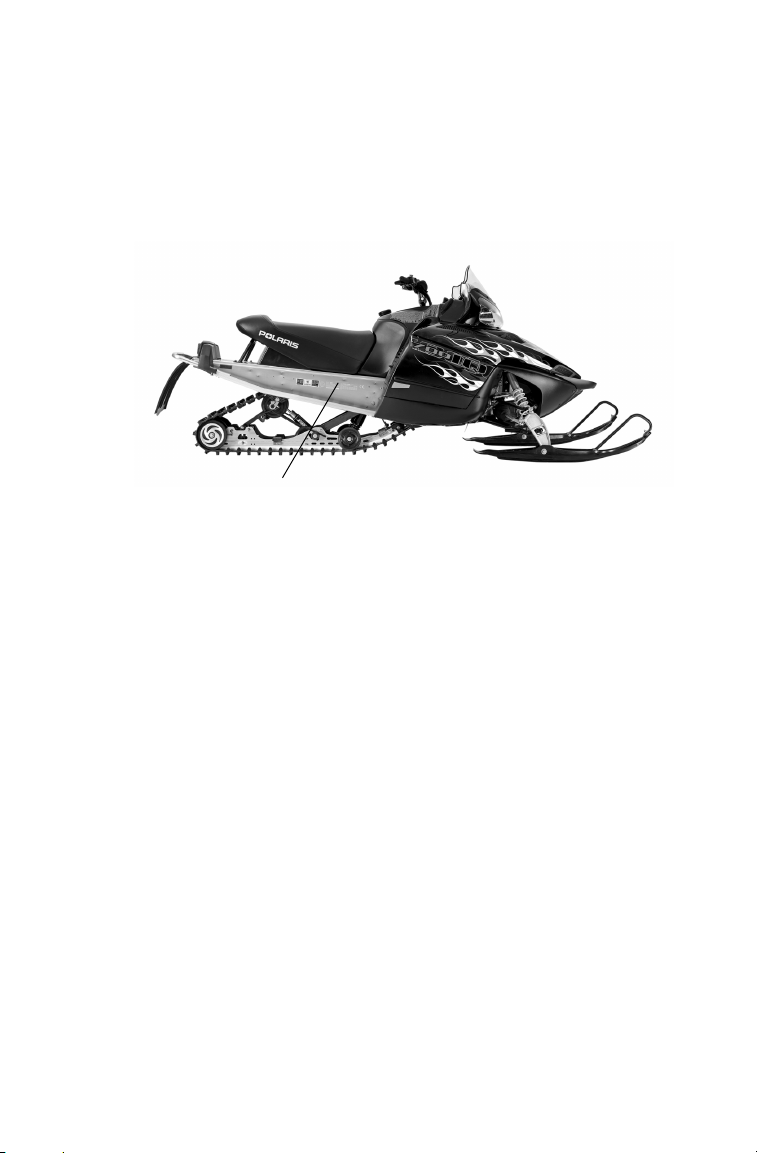
Stay Clear of Track
Your snowmobile is propelled by a revolving track that must be partially
exposed for proper operation.
WARNING
Serious injuries may result if hands, feet, or
clothing become entangled in the track. Be
alert when riding, and remain properly
seated to stay clear of the track.
Never hold the snowmobile up or stand
behind it while warming up the track. A
loose track or flying debris could cause
serious injury or death. We recommend
having your dealer perform all track service
and alignment procedures.
Stay Clear of Engine
Never attempt adjustments with the engine running. Turn off the ignition, raise the hood, make the adjustment, secure shields and guards,
secure the hood, and then restart the engine to check its operation.
WARNING
Serious injury can occur if fingers or clothing contact the moving parts of an
engine. Always stop the engine before attempting adjustments.
Riding Position
Operating a snowmobile requires skill and balance for proper control.
Rider positions may vary with experience and the features available on
some snowmobiles, but under many conditions, the proper position is to
be seated with both feet on the running boards and both hands on the
handlebar grips for proper throttle, brake and steering control.
WARNING
Improper riding position may reduce control and could result in serious injury
or death. Always ride in a position that allows for control of your vehicle.
10
Page 14
SAFETY
E
4
051039
0006.31
Operator Safety
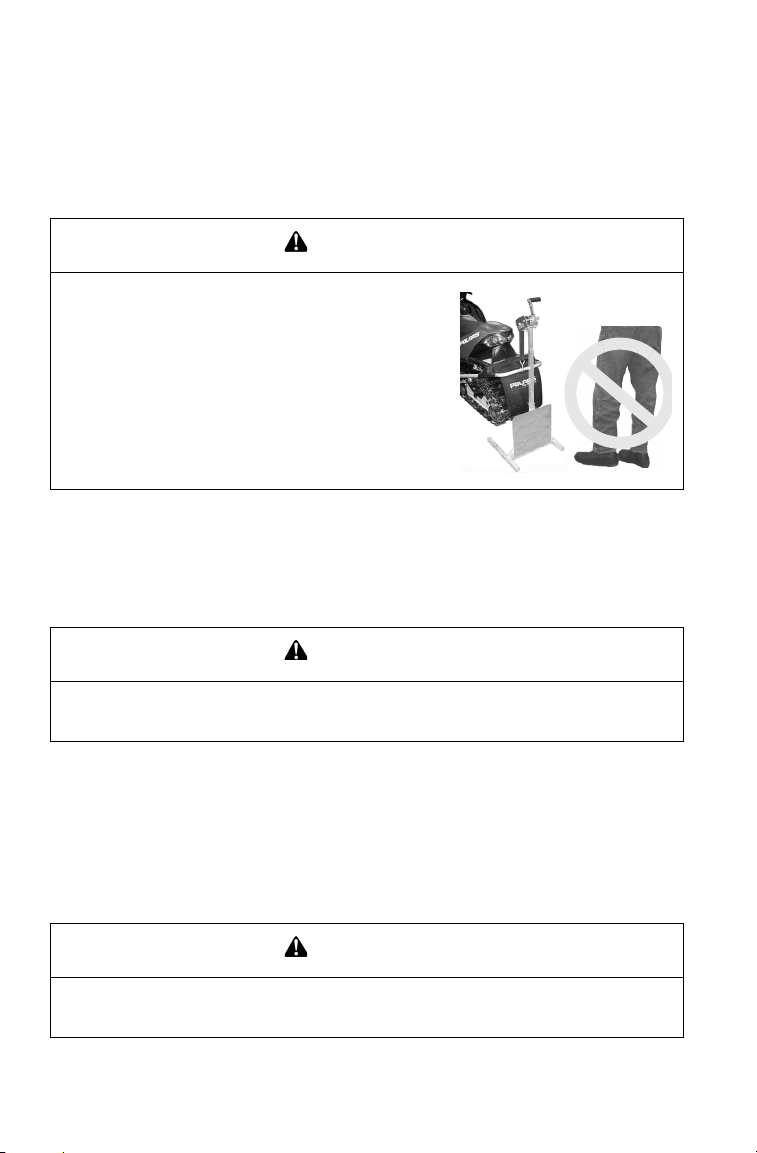
Riding Apparel
Be prepared, be warm and be comfortable when riding. Be aware of
the weather forecast, especially the
windchill, and dress accordingly.
See the chart on page 22.
WARNING
Avoid wearing loose clothing or
long scarves, which can become
entangled in moving parts and
cause serious injury.
Helmet
Wearing a helmet can prevent a severe head injury. Whenever riding a
Polaris vehicle, always wear a helmet that meets or exceeds established
safety standards.
Approved helmets in the USA and Canada bear a U.S. Department of
Transportation (DOT) label.
Approved helmets in Europe, Asia and Oceania
bear the ECE 22.05 label. The ECE mark consists
of a circle surrounding the letter E, followed by the
distinguishing number of the country which has
granted approval. The approval number and serial
number will also be displayed on the label.
Eye Protection
Do not depend on eyeglasses or sunglasses for eye protection. Whenever riding a Polaris vehicle, always wear shatterproof goggles or use a
shatterproof helmet face shield. Polaris recommends wearing approved
Personal Protective Equipment (PPE) bearing markings such as VESC
8, V-8, Z87.1, or CE. Make sure protective eye wear is kept clean.
11
Page 15

SAFETY
Operator Safety
Disabled Operators
Safe operation of this rider-active vehicle requires good judgement and
physical skills. Operators with cognitive or physical disabilities have an
increased risk of loss of control, which could result in serious injury or
death.
Survival Preparation
For your safety, always ride in a group of other snowmobilers. Always
tell someone where you're going and how long you expect to be gone. If
it isn't possible to ride with others, and you must travel into remote
areas, always carry survival equipment that's appropriate to the conditions you may encounter. Such equipment may include, but is not limited to: extra clothing, a sleeping bag, a flashlight, food and water, a
signaling mirror, a means of building a fire, and a two-way radio or cellular telephone.
For added protection, carry the following items on your snowmobile at
all times:
• Spare Drive Belt • Winter Survival Kit
• Extra Set of Spark Plugs • Trail Map
• Tow Rope • Owner's Manual
• Extra Oil • First Aid Kit
• Fuel Deicer • Tool Kit
12
Page 16
SAFETY
Operator Safety
Rider Capacity
Driving 1-Up - Some Polaris snowmobiles are designed for a single
rider only. A decal on the console of these models indicates single rider
operation.
Driving 2-Up - Some Polaris snowmobiles are designed for up to two
riders. A decal on the hood of these models indicates that the vehicle is
designed for one operator and one passenger only.
Machines designed for two riders should never be operated with more
than two people on board. When traveling with a passenger, it's the
driver's responsibility to operate the machine safely.
Slow down! Control becomes more difficult with two people on board.
More space is required to make turns, and longer distances are necessary
for stopping.
Excessive Speed
WARNING
High speed driving, especially at night, could result in serious injury or death.
Always reduce speed when driving at night or in inclement weather.
Always observe all laws governing snowmobile operation and speed
limits. Always be alert and pay attention to the trail ahead. Multiplying
speed (MPH) by 1.5 will equal the approximate number of feet per second your machine travels. If your speed is 40 MPH, your machine is
traveling about 60 feet per second. If you look back for only two seconds, your machine will travel about 120 feet. If your speed is 60 MPH,
your machine will travel about 180 feet in two seconds.
Traveling at night requires extra caution. Check headlight and taillight
to ensure proper operation, and don't over-drive your headlight beam.
Always be able to bring your machine to a stop in the distance illuminated by the headlight.
13
Page 17
SAFETY
RR
Operator Safety
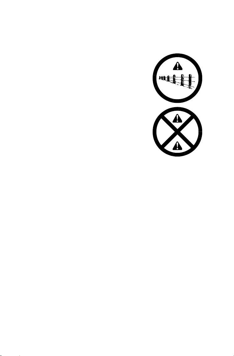
Driver Awareness
Slow down when traveling near poles,
posts, or other obstacles. Be especially
alert if you're snowmobiling after dark.
Always be on the alert for wire fences.
Single strands are especially dangerous,
since there may be a great distance
between posts. Guy wires on utility poles
are also difficult to distinguish.
Make sure the way is clear before crossing
railroads and other roads and highways.
The noise of your machine will drown out
the sound of approaching vehicles. Look
ahead, behind, and to both sides before
turning or crossing railroad tracks or highways. Steep embankments may also hide
your view. Always leave yourself a way
out.
Variances in snow depth and/or water currents may result in uneven ice
thickness. You may drown if you break through the ice. Avoid travelling
on frozen bodies of water.
When teaching inexperienced operators to ride, set up a predetermined
course for practice. Make sure they know how to drive and control the
snowmobile before allowing them to make longer trips. Teach them
proper snowmobile courtesy, and enroll them in driver's training and
safety courses.
14
Page 18

SAFETY
Operator Safety
Avalanches
Snowmobilers should always be properly
trained and equipped before traveling in
mountainous terrain:
• Take an avalanche class
• Travel with experienced people
• Travel on designated trails
• Make sure each person is equipped
with a shovel, probe and avalanche
beacon.
You don't have to be snowmobiling on a slope for an avalanche to occur.
Be aware that all of the snow is connected. You may be riding on a flat
slope or snow covered road, but if the snowpack above is unstable
enough you can trigger an avalanche on a steeper slope above you.
Always be aware of snow conditions above you as you travel in mountainous terrain.
Before riding in mountainous terrain, call or log on to your local avalanche advisory to get current weather and snow stability information.
For more information about avalanche training and avalanche conditions, contact local law enforcement in your area, or visit the American
and Canadian online avalanche centers at www.avalanche.org.
15
Page 19
SAFETY
Operator Safety
Ice and Snow Build-up
WARNING
Ice and snow build-up may interfere with the steering of your machine, resulting in serious injury or death. Keep the underhood area free of snow and ice.
Before driving, manually turn the skis to the left and right to be sure ice
and snow are not interfering with full left and right steering. If difficulty
is encountered, remove ice and snow build-up that may be obstructing
the steering linkage.
Driving on Slippery Surfaces
WARNING
Never attempt an abrupt change of direction when operating on slippery surfaces. Proceed slowly and use extra caution.
Driving on ice or hard-packed snow reduces steering and braking control,
which may result in loss of control and serious injury or death. Slow down
and use extra caution when operating on slippery surfaces.
16
Page 20

SAFETY
Operator Safety
Driving Downhill
When riding downhill, shift your weight to the rear of the machine and
reduce your speed to a minimum. Apply just enough throttle to keep the
clutch engaged, allowing the engine's compression to help slow the
machine and keep it from rolling freely downhill.
WARNING
When driving on long downhill stretches, pump the brakes. Riding the brakes
may cause the brake system to overheat, which may result in brake failure.
Excessive or repetitive use of the brakes for high speed stops will also cause
an overheated brake system. This condition may lead to a sudden loss of
brakes and/or fire and may result in serious injury or death.
17
Page 21

SAFETY
Operator Safety
Driving in Hilly Terrain
WARNING
Climbing a hill or crossing the face of a slope may result in loss of balance
and machine roll-over, causing serious injury or death. Use caution and good
judgement when driving in hilly terrain.
Use extra caution when operating in hilly terrain. If climbing a hill is
unavoidable, keep your weight low and forward. If you must cross the
face of a slope, keep your weight on the uphill side of the machine to
maintain proper balance and avoid possible roll-over.
Slow down when reaching the crest of a hill. Be prepared to react to
obstacles, sharp drops or other people or vehicles that may be on the
other side of the hill.
If you're unable to continue up a hill, turn the machine downhill before
it loses momentum. If this isn't possible, spin the track just enough to
dig in to prevent it from rolling back down the hill. Stop the engine and
set the parking brake (if equipped). Keeping away from the downhill
side of the machine, pull the rear of the snowmobile around and point
the front end and skis downhill. Remount the machine, restart the
engine, release the parking brake, and descend the hill carefully.
18
Page 22

SAFETY
Operator Safety
Drive Belt
Do not operate the engine with the drive belt removed.
Any servicing that requires operation without a belt must be performed
by your dealer. Operation of the engine with the belt removed may result
in injury or damage to the engine.
Intake Silencer
Do not operate the engine with the intake silencer or filter removed.
Damage to the engine may occur if the intake silencer or filter are
removed.
Clutches
Do not attempt to service the clutches.
All clutch service must be performed by your dealer. The clutch is a
complex mechanism that rotates at high speeds. Each clutch is dynamically balanced before installation. Any tampering may disrupt this precision balancing and create an unstable condition.
Cold Weather Drive-Away
Whenever your snowmobile has been parked for a length of time, especially overnight, always make sure the skis and track are loosened from
ice and snow before attempting to drive. Apply the throttle with enough
authority to put the machine into motion, but always operate within
safety limits.
Maneuverability
While much control and maneuverability is achieved through the steering system and skis, maximum control is achieved by the shifting of
your body weight. Maneuverability will change for lighter operators or
machines designed to carry a load.
19
Page 23
SAFETY
Operator Safety
Inadequate Snow Conditions
Since snow provides the only lubrication for the power slide suspension
and, on liquid cooled models, cooling for the engine, adequate snow
cover is a requirement for operation of your snowmobile.
NOTICE: Driving in too little snow will result in excessive wear and damage to
Inadequate cooling and lubrication will lead to overheating of the slide rail
and track, causing premature wear, damage and failure, which can result in
serious injury. Reduce speeds and frequently drive into fresh snow to allow
adequate cooling and polishing of the slide rail and track surfaces. Avoid
operating for prolonged periods on ice, hard-packed surfaces or roads.
Operating in Deep Snow
If the machine becomes stuck in snow, clear the running board area of
snow, then step down the snow in front of the machine so that when the
throttle is opened, the snowmobile will be able to climb up and over the
snow.
the slide rail, track and/or engine.
WARNING
20
Page 24

SAFETY
Operator Safety
Driving Responsibly
Every snowmobile handles differently, and even the most docile conditions may become dangerous if operators drive improperly. If you're
new to snowmobiling, acquaint yourself with the machine and with
what it will and won't do under various conditions. Even seasoned drivers should spend some time getting the feel for a machine before
attempting ambitious maneuvers.
• A snowmobile depends on the rider's body position for proper balance in executing turns, traversing hills, etc. Always start on a
smooth, level area to begin building your operating experience.
• Before allowing someone else to use your snowmobile, know the
extent of their operating skills. Check to see if they've taken a snowmobile safety course and have an operator's certificate. For their protection, as well as yours, make sure they take a snowmobile safety
course. Everyone can benefit from the course.
• Don't "jump" your snowmobile over large drifts or similar terrain.
Jumping may injure your back because of spinal compression that
could occur when the snowmobile impacts the ground. The seat and
suspension of your snowmobile have been designed to provide protection under normal riding conditions. Your snowmobile is not
intended for this kind of use.
• Be courteous to oncoming traffic by dimming your headlights and
reducing your speed.
• When traveling in a group of snowmobiles, don't tailgate (follow too
closely). Leave enough distance between snowmobiles to provide
ample stopping room and to provide protection from flying snow and
debris. Allow even more distance when driving on slippery surfaces
or when driving in darkness or other low visibility conditions. Be
aware of any snowmobile traffic around your vehicle. Drive defensively to avoid accidents.
• Remove the key from the ignition when you leave the snowmobile
unattended.
21
Page 25
SAFETY
Operator Safety
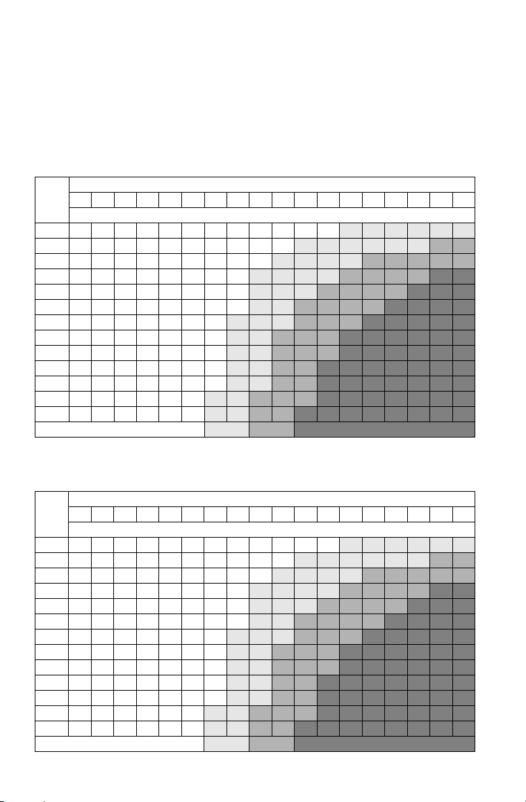
Windchill/Temperature Charts
The following information is provided to help you determine when temperatures become dangerous for riding.
WINDCHILL CHART (_F)
Wind
Speed
40 35 30 25 20 15 10 5 0 -5 -10 -15 -20 -25 -30 -35 -40 -45
in
MPH
Calm 40 35 30 25 20 15 10 5 0 -5 -10 -15
5 3631251913 7 1 -5-11-16
10 34 27 21 15 9 3 -4 -10 -16
15 32 25 19 13 6 0 -7 -13
20 30 24 17 11 4 -2 -9 -15
25 29 23 16 9 3 -4 -11 -17
30 28 22 15 8 1 -5 -12
35 28 21 14 7 0 -7 -14
40 27 20 13 6 -1 -8 -15
45 26 19 12 5 -2 -9 -16
50 26 19 12 4 -3 -10 -17
55 25 18 11 4 -3 -11
60 25 17 10 3 -4 -11
Frostbite in >>
Actual Thermometer Reading (_F)
Equivalent Temperature (_F)
-20 -25 -30 -35 -40 -45
-22 -28 -34 -40 -46 -52 -57 -63
-22 -28 -35 -41 -47 -53 -59 -66 -72
-19 -26 -32 -39 -45 -51 -58 -64 -71 -77
-22 -29 -35 -42 -48 -55 -61 -68 -74 -81
-24 -31 -37 -44 -51 -58 -64 -71 -78 -84
-19 -26 -33 -39 -46 -53 -60 -67 -73 -80 -87
-21 -27 -34 -41 -48 -55 -62 -69 -76 -82 -89
-22 -29 -36 -43 -50 -57 -64 -71 -78 -84 -91
-23 -30 -37 -44 -51 -58 -65 -72 -79 -86 -93
-24 -31 -38 -45 -52 -60 -67 -74 -81 -88 -95
-18 -25 -32 -39 -46 -54 -61 -68 -75 -82 -89 -97
-19 -26 -33 -40 -48 -55 -62 -69 -76 -84 -91 -98
30 min. 10 min. 5 min.
WINDCHILL CHART (_C)
Wind
Speed
5 2 -1 -4 -7 -10 -13 -16 -19 -22 -25 -28 -31 -34 -37 -40 -43 -46
in
KPH
Calm 5 2 -1 -4 -7 -10 -13 -16 -19 -22 -25 -28
8 3 0 -4 -7 -11 -14 -18 -22 -25 -29
16 2 -2 -6 -10 -13 -17 -21 -24 -28
24 1 -3 -7 -11 -15 -19 -22 -26
32 0 -4 -8 -12 -16 -20 -24 -28
40 -1 -5 -9 -13 -17 -21 -25 -29
48 -1 -5 -9 -13 -18 -22 -26
56 -2 -6 -10 -14 -18 -22 -26
64 -2 -6 -10 -15 -19 -23 -27
72 -2 -7 -11 -15 -19 -23 -28
80 -3 -7 -11 -15 -20 -24 -28
88 -3 -7 -12 -16 -20 -24
96 -3 -8 -12 -16 -21 -25
Frostbite in >>
22
Actual Thermometer Reading (_C)
Equivalent Temperature (_C)
-32 -36 -39 -43 -46 -50 -53 -57
-32 -36 -39 -43 -47 -50 -54 -58 -62
-30 -34 -38 -42 -45 -49 -53 -57 -61 -65
-32 -36 -39 -43 -47 -51 -55 -59 -63 -67
-33 -37 -41 -45 -49 -53 -57 -61 -65 -69
-30 -34 -38 -42 -46 -50 -54 -58 -62 -66 -70
-31 -35 -39 -43 -47 -51 -55 -59 -64 -68 -72
-31 -35 -40 -44 -48 -52 -56 -61 -65 -69 -73
-32 -36 -40 -45 -49 -53 -57 -61 -66 -70 -74
-33 -37 -41 -45 -50 -54 -58 -62 -67 -71 -75
-29 -33 -37 -42 -46 -50 -55 -59 -63 -67 -72 -76
-29 -34 -38 -42 -47 -51 -55 -60 -64 -68 -73 -77
30 min. 10 min. 5 min.
-31 -34 -37 -40 -43 -46
Page 26

SAFETY
Safety Decals and Locations
Warning decals have been placed on the snowmobile for your protection. Read and follow the instructions of the decals and other warnings
on the snowmobile carefully. If any of the decals depicted in this manual
differ from the decals on your snowmobile, always read and follow the
instructions of the decals on the snowmobile.
If any decal becomes illegible or comes off, contact your Polaris dealer
to purchase a replacement. Replacement safety decals are provided by
Polaris at no charge. The part number is printed on the decal.
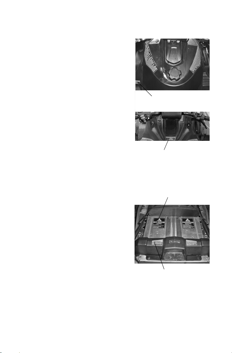
Clutch Cover Warning
This warning decal is found under the hood on the clutch cover:
WARNING
Do not operate engine with hood open.
Do not attempt adjustment with engine running.
Do not operate engine with plenum/belt guard removed.
Never run engine with drive belt removed.
Never service clutches yourself -- see your dealer.
Pressure Cap Warning
This warning decal is found under the hood on the pressure cap of applicable liquid cooled models:
Do not open hot. Test or replace when changing coolant. Press
down and turn to release cap. 13 PSI
23
Page 27
SAFETY
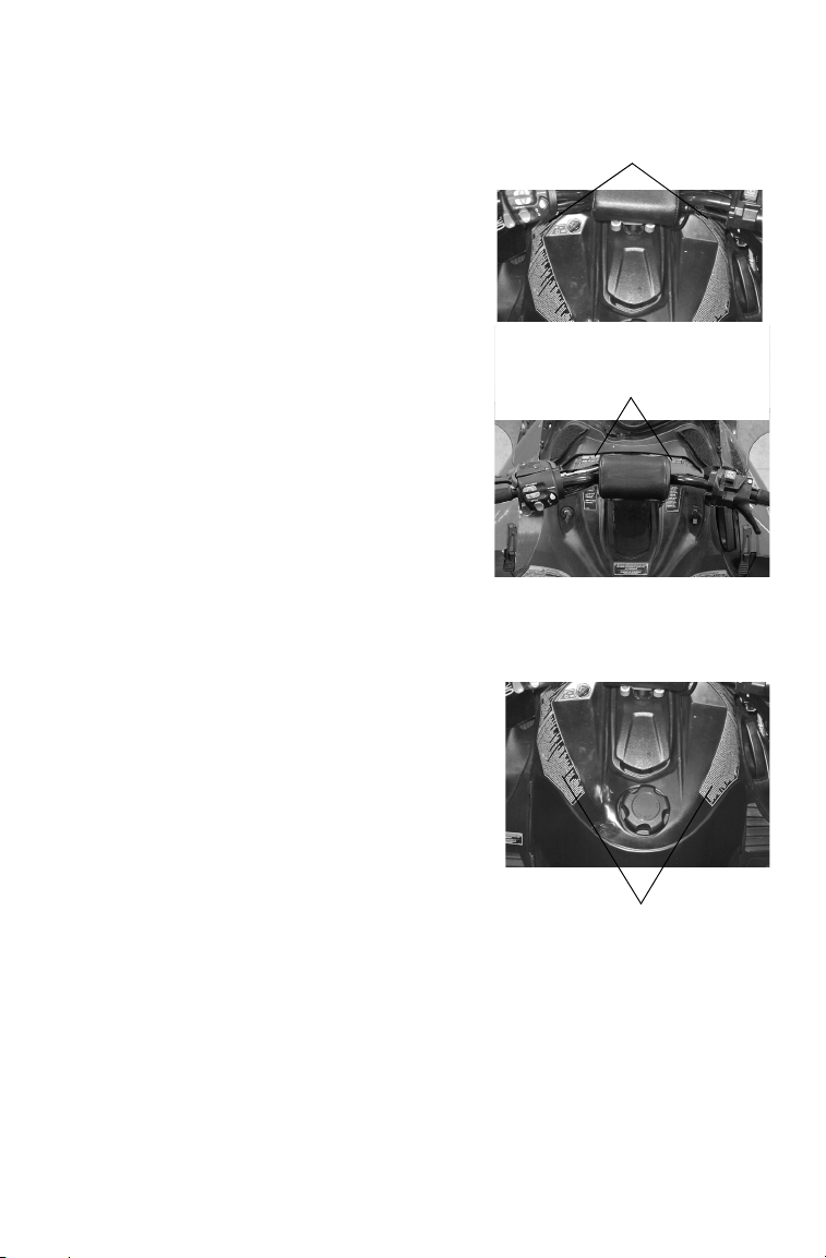
“No Passenger”
Warning
“One Passenger”
Warning
Track Warning
Hot Surface Warning
Safety Decals and Locations
“No Passenger” Warning
Snowmobiles designed for a single rider
only have the NO PASSENGER warning
decal on the lower left side of the console:
WARNING
This vehicle is designed for operator
only. NO PASSENGER
“One Passenger” Warning
Snowmobiles designed for an operator and
one passenger have the ONE PASSENGER warning decal below the steering
post:
WARNING
This vehicle is designed for operator
and ONE passenger only.
For more information about operating with
a passenger, see page 13.
Hot Surface Warning
The hot surface warning is located near
the rear of the tunnel:
WARNING
HOT SURFACE - DO NOT TOUCH
Burn may result. Entire top of tunnel
may be hot.
Install only accessories specifically
approved for this model by Polaris.
Track Warning
The track warning decal is at the rear of
the tunnel:
WARNING
Stay clear of track. Do not sit on seat back. Entanglement with the
track or a fall from seat back may result in severe injury or death.
24
Page 28
SAFETY
Reverse Warning
Reverse Warning
Operation
Warning
Safety Decals and Locations
Reverse Warning
The reverse warning decal is located on
the console, either beside the steering post
or below the windshield:
WARNING
Reverse operation, even at low speeds,
can cause loss of control resulting in
serious injury or death. To avoid loss
of control, always:
• Look behind before and while backing up.
• Avoid sharp turns.
• Shift to or from reverse only when
stopped.
• Apply throttle slowly.
NOTE: For more information, see
Owner's Manual.
If electric reverse:
• Machine stopped and engine at idle, push yellow button on LH control to reverse. Flashing light on dash indicates reverse operation.
• Push button again to return to forward.
Operation Warning
The operation warning decal is also
located on the console. See page 26 for the
text.
25
Page 29

SAFETY
Safety Decals and Locations
Operation Warning
• To avoid serious injury or death, read and understand all warnings
and the Owner's Manual before operation. If manual is missing, contact a Polaris dealer for a replacement.
• This vehicle is capable of high speeds. Buried objects or uneven
terrain can cause loss of control. Reduce speed and use extreme
caution when operating in unfamiliar terrain.
• Excessive speed, especially at night or with limited visibility, can
result in insufficient time for you to react to terrain changes, to
avoid unexpected obstacles, or to stop safely.
• Never consume alcohol or drugs before or while operating this vehicle.
• In an emergency, push down the Auxiliary Shut-Off Switch, located
on the top of the throttle control assembly, to stop the engine. Then
pull the brake lever to stop.
• Always wear an approved helmet, eye protection, and adequate
clothing while operating this vehicle.
• This vehicle is designed for adult use only. Check local laws for age
requirements.
• When operating with a passenger (on approved models only)
reduce speed and allow extra space for steering and stopping. A
passenger reduces your ability to control the vehicle.
• When operating on hard-packed snow, ice, or when crossing roads,
steering and braking ability are greatly reduced. Reduce speed and
allow extra space to turn or stop.
• To maintain vehicle control on ice or hard-packed surfaces, you
should have a proper balance of ski carbides to track studs. See
Owner's Manual for proper use of traction products.
• Repeated stops from high speed may cause fading or sudden loss
of braking ability.
• Parking brake may relax when used for long periods. Do not leave
brake engaged for more than five minutes.
• Before starting engine, check throttle, brake, and steering for
proper operation. Make sure hood is latched. Be seated and in position to control the vehicle.
Oil injection system: Use unmixed fuel only. Check oil level when
refueling.
26
Page 30
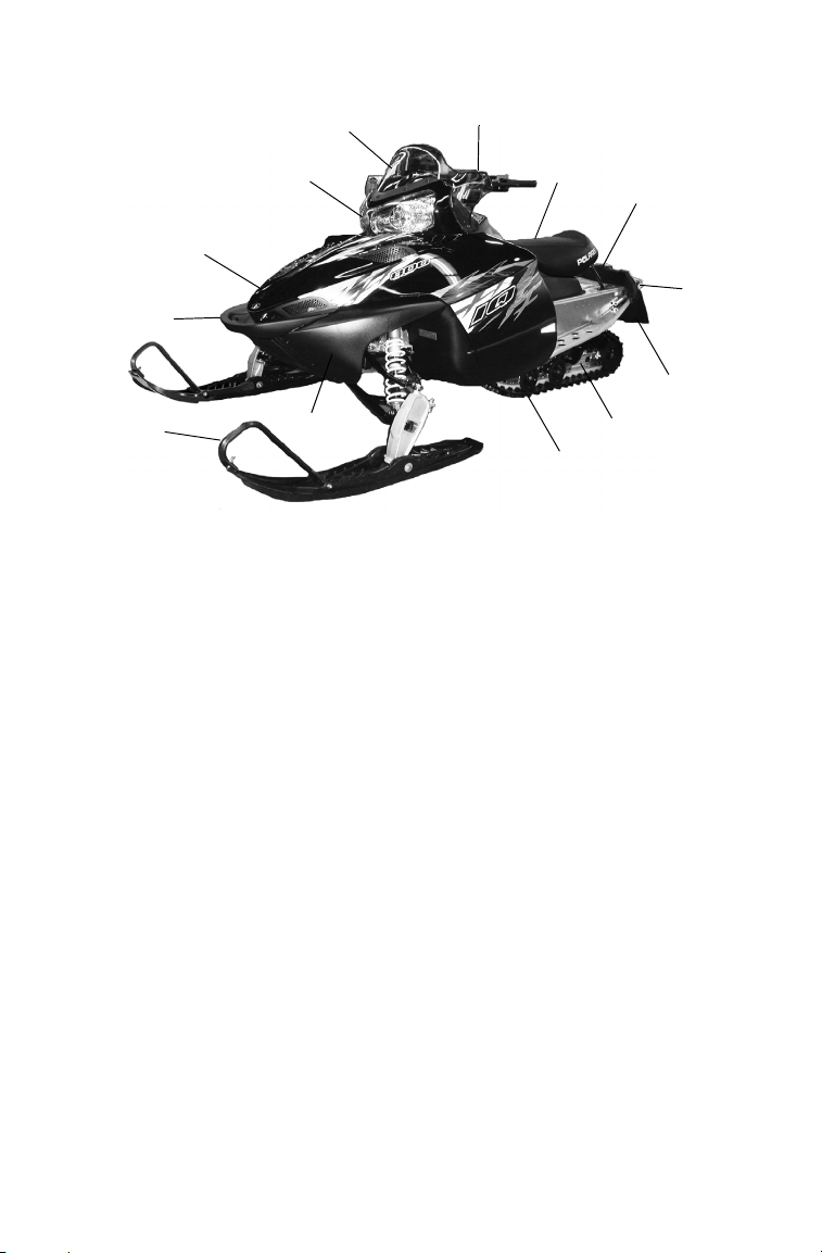
Not all models are equipped with all features shown.
8
13
5
6
7
12
11
2
1
3
4
10
9
1. Nosepan
2. Skis
3. Front Bumper (do not use for
pulling or dragging the snowmobile)
4. Hood
5. Headlight
6. Windshield
7. Handlebar
8. Operator Seat
9. Taillight
10. Rear Bumper
11. Snow Flap
12. Suspension
13. Track
FEATURES
27
Page 31

FEATURES
1
2
4
5
7
6
3
12
11
13
89 10
14
Not all models are equipped with all features shown.
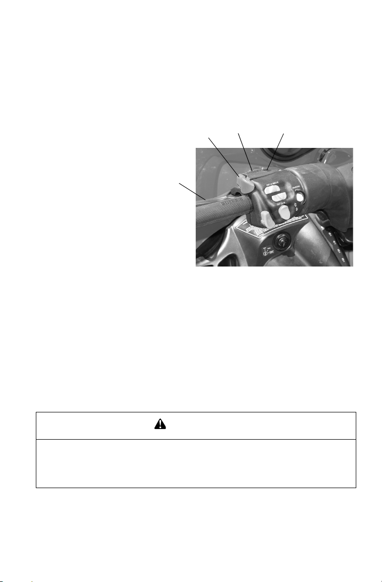
1. Fuel Filler Cap
2. Ignition Switch
3. MFD Gauge
4. Engine Stop Switch
5. Throttle Control
6. Recoil Starter Handle
7. Hood Hold Down Straps
8. Parking Brake Lock
9. Handlebar Grip Warmer Switch
10. Thumbwarmer Switch
11. Electronic Reverse Button
12. Multi-Function Display (MFD)
Control
13. Headlight Dimmer Switch
14. Brake Lever
28
Page 32

FEATURES
+
Cargo Area
The maximum weight capacity for the
cargo area is 15 lbs. (7 kg). Install only
accessories specifically approved for this
model by Polaris. Always secure cargo
before operating. Do not exceed the cargo
area weight limit.
Adjustable Headlights
Adjust the headlight beam by moving the
adjuster to the left or right.
Detonation Elimination
Technology (DET)
The DET system prevents damage to the engine from detonation by
automatically reducing the engine timing and adding fuel whenever the
sensors detect detonation.
You may notice decreased engine RPM and performance when DET is
activated, but in most cases DET activation is temporary, and the timing
will return to normal automatically. In extreme conditions the DET system retards timing and holds it in a retarded state. If this occurs, replace
the fuel with recommended fuel or see your Polaris dealer for service.
Cause of DET Activation Solution
Poor quality fuel Replace with higher quality fuel
Improper engine modifications Do not modify the engine
Sensor Fail-Safe
The DET includes a sensor fail-safe system to prevent the engine from
damage if the sensor fails, becomes disconnected or is unable to detect
detonation. The rider will experience a loss of power. The sensor must
be reconnected or repaired to regain full power. See your Polaris dealer
for service if this occurs.
TIP: The check engine light will flash six times if the sensor fails or becomes dis-
connected.
29
Page 33

FEATURES
1
2
3
4
5
6
7
8
1
2
3
4
5
6
7
Instrumentation
MFD Component Identification
Item
1 Analog (if equipped)
2 Digital Gauge
3 CHECK ENGINE
Indicator (carb models)
4 Low Oil Indicator
5 High Temp Indicator
6 Brake Indicator
7 Reverse Indicator
8 High Beam Indicator
Digital Display Identification
Item
1 RPM or Speed
Altitude (if equipped)
Service Interval
2 Electrical System
Voltage Level
3 MAX - Maximum MPH/
4 Air Temp (if equipped)
5Miles
6Hours
7 Fuel Level (if equipped)
KPH or RPM
MPH -Miles per hour
KPH - Kilometers per hour
RPM -Engine crankshaft
revolutions per
minute
Engine Temp
Degrees Celsius
Degrees Fahrenheit
Kilometers
Tri p 1/ Tr ip 2 / Tri p F
Service Label
Altitude Label
30
Page 34

FEATURES
+
Instrumentation
MFD Settings
With the engine running, use the
MFD Control Switch to set the MFD
display to your preference. The
rocker switch (+) has a MODE button (top) and a SET button (bottom).
Standard vs. Metric
The MFD will display either standard or metric units of measurement.
While viewing a screen that displays
measurements (MPH, KPH or temperatures), press and hold the MODE switch until the unit of measurement changes (about 10 seconds).
Speedometer/Tachometer
The speedometer and tachometer can be viewed in either the analog or
the digital display. If the analog display is set to show speedometer readings, the digital screen will automatically display the tachometer (option
1). If the analog is set to show the tachometer, the digital screen will
show the speedometer (option 2).
To change preferences, press and hold the MODE button for three seconds. When the button is released, the new setting becomes active and
screen colors change. See table below.
Option
1 Speed RPM Blue “mph” Blue
2 RPM Speed Red
Analog
Display
Digital
Display
Analog
Screen
“X100rpm”
Digital
Screen
Backlight
Red
Backlight
31
Page 35

FEATURES
Instrumentation
MFD Digital Display Programs
Press the MODE button to cycle through the three MFD programs: Performance, Engine and History. Each program will remain in the display
until another is selected.
TIP: The analog will always display either MPH or engine RPM (whichever set-
ting is selected) regardless of the display program being viewed.
Performance Program
The Performance Program automatically displays either speed or
tachometer, whichever is opposite the analog display. See page 31. It
also displays electrical system voltage and fuel level (if equipped).
While in the Performance mode, press the SET button to cycle through
the odometer, Trip 1, Trip 2, Trip F (if equipped with electronic fuel
gauge) and Clock settings.
32
Page 36

Instrumentation
MFD Digital Display Programs
Trip Settings
Trip 1 and Trip 2 are odometers used to
check fuel mileage or to keep track of
distance traveled.
1. To reset a trip odometer to zero,
enter the Trip 1 or Trip 2 display.
2. Press and hold the SET button for
two seconds.
If the snowmobile is equipped with an
electronic fuel gauge, Trip F automatically displays when the fuel level is low.
The fuel symbol and the last fuel bar on
the MFD gauge will blink when the fuel
level reaches 1/8th tank. The Trip F
odometer records distance traveled until
enough fuel is added to raise the level
above 1/4 tank. The fuel symbol and the
fuel bar will continue to blink until the
fuel level is above 1/4 tank. The Trip F
odometer will automatically reset to zero
after refueling.
FEATURES
Odometer Setting
The odometer records the vehicle's total
distance traveled since manufacture. The
odometer cannot be reset.
33
Page 37

FEATURES
Instrumentation
MFD Digital Display Programs
Performance Program
Clock Setting
1. While in the CLOCK display, press
and hold the SET button for five
seconds.
2. When the hour starts flashing press
the SET switch once to advance
one hour, or press and hold the
SET button to advance the hour
once every 0.2 seconds.
3. Press the MODE button to save the hour and flash the minutes.
4. Set the minutes in the same manner.
5. When finished, press the MODE button to save the new setting. If
the MODE button is not pressed within ten seconds, the clock will
automatically save the new entry.
34
Page 38

FEATURES
Instrumentation
MFD Digital Display Programs
Engine Program
The Engine Program automatically displays the engine coolant temperature, engine hours, electrical system voltage level and fuel level (if
equipped). On machines equipped with altimeter sensor and ambient air
temperature sensors, altitude and ambient air temperature will display as
additional screens in the engine program. Press the SET button to display the ambient air temperature and altitude screens.
Air Temperature (if equipped)
The MFD displays actual air temperature.
Press and hold the MODE switch for ten
seconds to switch between standard and
metric units of measurement.
Hour Meter
The hour meter records the total hours of
engine operation since manufacture. This
meter cannot be reset.
Engine Temperature
A thermometer measures water temperature,
giving an indication of engine temperature.
35
Page 39

FEATURES
Instrumentation
MFD Digital Display Programs
Engine Program
Altitude (if equipped)
The rider can calibrate the altimeter for current
atmospheric conditions. Altimeter accuracy
will be +/-300 ft. (91 m) after adjustment.
TIP: Press and hold the MODE switch for ten sec-
onds to switch between standard and metric
units of measurement. When "ALt" displays,
the program is in the metric mode.
1. Enter the Engine Program and select the altimeter display.
2. Press and hold the SET button for five seconds.
3. When the digits begin to flash, press the SET button once to
advance 50 feet (15 m), or press and hold the button to advance 100
ft. (30 m) every 0.1 seconds. Adjust the altitude display to within 50
ft. (15 m) of current altitude.
TIP: The gauge reads barometric pressure and allows the rider to compensate
for daily fluctuations in air pressure. The gauge can adjust the displayed
altitude to +/- 1300 ft. (396 m) from the preset value. It will adjust up to
+1300 ft. (396 m) above the calibrated altitude. Once the +1300 ft. (396 m)
offset has been reached, the next adjustment is -1300 ft. (396 m) from the
calibrated altitude, and 50 ft. (15 m) will be added to the altitude each time
the SET button is pressed.
4. Press the MODE button to hold the reading at the adjusted value. If
it's not pressed within five seconds, the gauge will automatically
save the new setting.
36
Page 40

FEATURES
Instrumentation
MFD Digital Display Programs
History Program
The History Program automatically displays electrical system voltage
level and fuel level (if equipped).
While in the History mode, press the SET button to view maximum
vehicle speed, maximum engine rpm or the current service interval setting. The gauge automatically logs the maximum speed and engine rpm
even if the History Program is not currently displayed.
The History Program will display the history of the Maximum Speed,
Maximum RPM and Service Interval settings.
Maximum Speed/RPM Reset
While in either the MAX MPH or the MAX
RPM mode, press and hold the SET button
for three seconds to reset the recorded maximum values for both MPH and RPM. Both
of these values are reset at the same time.
Reset the MAX MPH/RPM values before
each run to obtain accurate readings.
TIP: Due to electrical noise, the MFD may occa-
sionally display MAX MPH/RPM values that
are not representative of actual values.
37
Page 41

FEATURES
Instrumentation
MFD Digital Display Programs
Service Interval Reminder
The gauge logs the number of engine
hours between service reminders.
When the logged hours reaches the
designated service interval (set by the
user), the gauge provides a reminder
that service is due. "SErVCE" will
flash in the odometer area and "ENG"
will flash in the icon area for five seconds each time the vehicle is started until the service reminder is reset.
To reset the reminder at the existing interval:
1. Enter the service interval screen.
2. Press and hold the SET button for ten seconds, continuing to hold
even after the display begins to flash.
3. When the display stops flashing, release the button. The service
interval has been reset.
To reset the reminder at a new interval:
1. Enter the service interval screen.
2. Press and hold the SET button for five seconds, until the hours
begin to flash.
3. Immediately release the button.
4. Press the button again up to five times to advance the reminder in
50-hour increments. The maximum interval is 250 hours.
To disable the service interval reminder, press the SET button once after
reaching 250 hours on the display. The gauge will display "OFF".
38
Page 42

FEATURES
Instrumentation
MFD Battery Replacement (models with clocks)
If the clock function of the MFD isn't
working properly, replace the battery.
Replacement batteries are available from
your dealer.
1. Remove the plenum from the underside of the hood.
2. Locate the black battery compart-
ment. It has a red wire and a brown
wire with a white stripe. It's located
about three inches down the main
harness from the point where the
harness connects to the MFD.
3. Cut the plastic cable tie from the out-
side of the compartment.
4. Carefully cut the bottom of the com-
partment (opposite the wires) to separate the heat-sealed seams.
Squeeze the corners of the compartment inward so the battery is
visible.
TIP: Note the orientation of the battery before removing it. An incorrectly
installed battery will not maintain the clock.
5. Using needle-nose pliers, grasp the battery and rotate it so the lead-
ing edge of the battery is raised slightly away from the battery
holder. Pull the battery out gently.
TIP: The battery will not come out of the holder unless the leading edge of the
battery is raised. Hold the battery compartment, not the wires, while removing the battery. Pulling on the wires will separate them from the battery
holder.
39
Page 43

FEATURES
Instrumentation
MFD Battery Replacement (models with clocks)
6. Install a new battery with fingers only.
7. Seal the end of the battery compartment using high strength doublesided tape between the two compartment halves or high strength
single-sided tape around the outside of the compartment.
8. Make sure the taped seam of the compartment faces the downward
side of the wire harness.
9. Install a cable tie to secure the compartment to the wire harness in
the same location where the previous cable tie was located. Make
sure the battery wires are not stretched tight.
Gauge Cleaning
1. Wipe the gauge face as needed using a clean cloth and a mild soap
and water solution. Wipe dry with clean, soft cloth.
2. Clean the back side of the gauge using a clean cloth and a mild soap
and water solution. Do not remove the electrical connectors or protective rubber boot. Do not spray the back side of the gauge or the
wire harness with a pressure washer or other water source.
NOTICE: To prevent damage to the lens, do not use alcohol for cleaning. Do not
allow chemicals or sprays to come into contact with the lens. Immediately clean off any gasoline that splashes on the gauge during refueling.
40
Page 44

THE PERFECT FIT
1
2
3
4
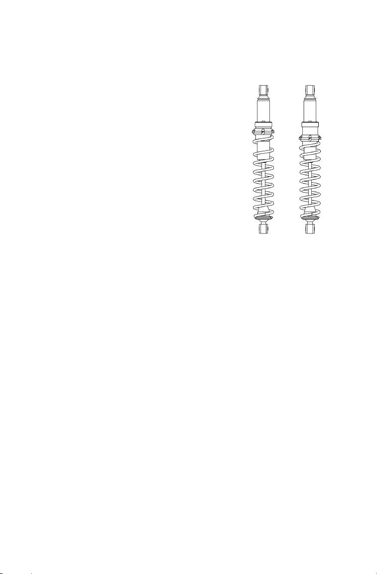
Front Suspension Adjustments
Independent Front Suspension (IFS)
Break in the suspension for about 150 miles (240 km) before making
any fine-tuning adjustments.
Settings will vary from rider to rider, depending on rider weight, vehicle
speed, riding style, and trail conditions. We recommend starting with
factory settings and then customizing each adjustment individually to
suit rider preference. The machine should be methodically tested, one
change at a time, under the same conditions (trail and snow conditions,
vehicle speed, riding position, etc.) after each adjustment until the best
ride is achieved.
IFS Components
1. Skis
2. Front shocks and springs
3. Rod ends
4. A-arms
IFS Adjustment Options
• Front shock spring preload
• Optional springs
• Optional shock valving
• Compression damping (SP
models)
41
Page 45
THE PERFECT FIT
Low
Preload
High
Preload
Front Suspension Adjustments
Shock Spring Preload
Increasing spring preload will increase
ski-to-ground pressure. Decreasing spring
preload will decrease ski-to-ground pressure. When adjusting, be sure the springs
on both the left and right sides of the
machine are at the same adjustment.
To change front shock spring preload,
grasp the spring and rotate it.
Increasing the spring preload too much
may adversely affect the handling of the
snowmobile and the performance of the
suspension. Never exceed one inch of preload beyond the factory settings, and
ensure that both sides are adjusted the
same. When decreasing preload, make
sure at least two turns of preload are holding the spring between the retainer on the
top of the shock and the threaded spring
preload adjuster nut on the shock body. Failure to do so could cause the
retainer to fall off when the suspension is fully extended.
TIP: Not all models have shocks with thread-adjustable spring preload. See your
dealer for more information.
NOTICE: On some models equipped with a plastic adjuster nut, the nut will
break if it is unscrewed from the threaded body. Do not force the nut if
resistance suddenly increases while you’re turning it.
42
Page 46

THE PERFECT FIT
Softer
Stiffer
Front Suspension Adjustments
Shock Compression Damping (SP models)
Turn the adjuster to make adjustments
to the compression damping. When
adjusting, we recommend that you turn
the adjuster only one click, then test
ride. Always adjust both shocks
equally.
The standard setting is 4 clicks from
the softest position.
• Turn the adjuster to the left for a
stiffer ride.
• Turn the adjuster to the right for a
softer ride.
Shock Valving
Some shocks can be revalved if spring preload alone isn't sufficient and
further adjustment is desired to control suspension stiffness. Please see
your Polaris dealer.
WARNING
Changing shock valving requires special tools and a sound knowledge of
mechanical theory, tool use, and shop procedures to perform the work safely
and correctly. Shocks contain high-pressure nitrogen gas. Use extreme caution when handling high-pressure service equipment. We recommend that
this work be performed by a Polaris dealer.
43
Page 47

THE PERFECT FIT
Rear Suspension Adjustments
Rider weight, riding style, trail conditions, and vehicle speed all affect
suspension action.
Each rear suspension can be adjusted to suit rider preference and deliver
excellent performance for a given set of conditions. However, all suspension designs and adjustments involve a compromise, or trade-off.
For example, a suspension set up for snowcross racing would provide a
very stiff ride on the trail. A suspension set up for trail riding would bottom out harshly on a snowcross course.
Refer to the suspension setup label on your snowmobile, or see your
Polaris dealer for initial suspension setup information. Additional
adjustments can be made after initial setup. Make adjustments to one
area at a time so you can evaluate the change. For further assistance, see
your dealer.
44
Page 48

THE PERFECT FIT
Rear Suspension Adjustments
Suspension Performance Tips
• Rider weight usually determines the position at which the spring preload should be set. However, this may vary with riding style. With a
little experimentation, each rider can find a preferred setup. These
adjustments are easy to make, involve very little time or effort, and
greatly affect the ride.
• In deep snow, a new rail slide will offer improved performance over
worn rail slide. It can also improve top speed.
• When riding on ice or hard-packed snow, adding a set of bogie wheels
to the rail may enhance the machine's performance. Bogie wheel kits
are available from your dealer.
• Polaris offers track kits for improved flotation in deep snow. See your
dealer for assistance.
• Keep the suspension pivot points lubricated. This will reduce moisture and rust build-up and ensure proper function of the suspension
components. Grease rear suspension pivots before adjusting the rear
suspension. Refer to Suspension Maintenance beginning on page 114.
Track Tension
Track adjustment is critical for proper handling. Always maintain correct tension and alignment. Refer to the track tension maintenance section beginning on page 108.
45
Page 49

THE PERFECT FIT
X
Y
Rear Suspension Adjustments
Initial Spring Preload Setting (Sag Method)
To set up the rear suspension torsion spring preload, measure the
distance between the ground and
rear bumper. This is measurement
X.
Take the first measurement with no
rider and with the rear suspension at
full extension. The rear bumper
may need to be lifted upward
slightly to fully extend the rear suspension.
Next, have the rider drop down hard
on the seat and bounce up and down
several times, collapsing the rear
suspension. With the rider seated,
measure the distance between the
ground and the rear bumper at the
exact location used for measurement X. This is measurement Y.
46
Page 50

THE PERFECT FIT
Rear Suspension Adjustments
Initial Spring Preload Setting (Sag Method)
To determine sag, commonly referred to as ride-in, subtract measurement Y from X (sag=X-Y). If the measured sag is incorrect, adjust the
FRA position and/or rear torsion spring preload.
Suspension Recommended Sag Adjustment
IQ (121) 4-5 inches (10-13 cm) Torsion Spring
Preload
SwitchBack
(136)
TIP: This is only an initial setup, and final spring preload may vary based on rider
preference and riding conditions.
4-5 inches (10-13 cm) Torsion Spring
Preload
See
Page
48
48
47
Page 51

THE PERFECT FIT
Soft Medium Firm
Rear Suspension Adjustments
Torsion Spring Preload
To adjust rear torsion spring preload, rotate the three-position cam using
the engine spark plug tool. Adjustment is easiest when the cam is
rotated from low to medium, and then to high. Rotating directly from
low to high will require significantly more effort.
Different rate torsion springs are available if a firmer ride is desired. See
your dealer for more information.
48
Page 52

THE PERFECT FIT
Upper
Nuts
Rear Suspension Adjustments
Limiter Strap Position (Ski Pressure)
Ski pressure is set at the factory to
deliver the optimum balance
between ride and handling. If a
rider prefers more ski pressure for
improved steering performance,
adjustments can be made to the
front limiter straps. Tighten the
straps to increase ski pressure.
Loosen the straps to reduce ski
pressure.
SP models have only one limiter
strap.
1. Remove the nuts and flat washers from the upper limiter straps.
2. Relocate the straps to the desired position.
3. Reinstall the nuts and washers. Tighten securely.
49
Page 53

THE PERFECT FIT
Stiffer Softer
Rear Suspension Adjustments
Rear Shock Compression Damping (Premium Shock)
Front Track Shock Compression Damping (SP Models)
Turn the adjuster on the shock
reservoir to make adjustments to the
compression damping. Positions are
labeled on the shock. When
adjusting, we recommend that you
turn the adjuster one click, then test
ride.
• Turn the adjuster clockwise for a
stiffer ride.
• Turn the adjuster counterclockwise
for a softer ride.
50
Page 54

THE PERFECT FIT
Rear Suspension Adjustments
Suspension Coupling
On all Polaris snowmobile rear suspensions, there are two torque arms
that control the movement of the rail beam. Prior to the advent of suspension coupling, these torque arms could move independently of each
other. Rear suspension coupling links the movement of the front and
rear torque arms to each other. There are two types of rear suspension
coupling.
Front To Rear Coupling and the Front Rear Scissor Stop
(FRSS)
The front rear scissor stop (FRSS) couples the movement of the front
torque arm with the rear torque arm and limits the amount of independence between the movement of the front torque arm and the rear torque
arm.
When hitting a bump, the front torque arm starts to compress. The FRSS
links that movement to the rear torque arm, causing it to compress and
raise the rear suspension up as one, allowing the suspension to hit the
bump only once and reducing kickback.
The factory setting is usually adequate for all riders and conditions.
51
Page 55

THE PERFECT FIT
Rear Suspension Adjustments
Rear To Front Coupling and the Rear Rear Scissor Stop
(RRSS)
The rear rear scissor stop (RRSS) couples the movement of the rear
torque arm with the front torque arm and limits the amount of independent movement between the rear torque and the front torque arm.
Adjusting the RRSS either allows more weight to transfer to the rear for
more traction, or allows less weight to transfer to the rear, resulting in
improved cornering performance. An adjustment dot is located on the
RRSS. This dot is on the longest end of the scissor stop.
Rear Rear Scissor Stop (RRSS) - Attributes
Moving the RRSS to a higher position will have the following effects on
the suspension:
• Reduced weight transfer.
• Improved chatter bump ride.
• Improved cornering performance.
52
Page 56

THE PERFECT FIT
HIGH
LOWLOW
MEDIUM
RRSS
FRSS
Rear Suspension Adjustments
Weight Transfer During Acceleration
The preferred method for controlling weight transfer during acceleration is by adjusting the rear rear
scissor stop (RRSS). The factory
setting is the best for most trail
riding conditions.
To decrease weight transfer under
acceleration (for improved cornering), rotate the RRSS to a higher
position.
To increase weight transfer or ski
lift during acceleration, rotate the
RRSS to a lower position.
TIP: Your dealer can help you with ini-
tial setup and additional setup
instructions to help you achieve
your optimum ride. A scissor stop
tool is also available from your
dealer.
53
Page 57

THE PERFECT FIT
Loosen top bolts to adjust
handlebar angle
Loosen bottom bolts to
adjust handlebar position
Handlebar Adjustments
Handlebar Position
1. Loosen the four bolts on the
bottom of the adjuster block.
If necessary, pry the blocks
apart with a screwdriver.
2. Adjust the handlebar forward
or rearward to the desired
position.
3. Tighten the bolts.
Handlebar Angle
1. Loosen the four bolts on the
top of the adjuster block. If
necessary, pry the blocks
apart with a screwdriver.
2. Adjust the handlebar forward
or rearward to the desired
angle.
3. Tighten the bolts.
54
Page 58

THE PERFECT FIT
Accessories
Polaris offers a wide range of accessories for your snowmobile to help
make each ride more enjoyable.
Use only Polaris parts and accessories on your Polaris snowmobile. Use
of unapproved parts and accessories may result in:
• Non-compliance with government/industry requirements
• Voiding of warranty
• Injury to self or others
This applies, but is not limited to the following areas: brakes, clutches,
fuel systems, and exhaust systems. Exhaust systems are critical safety
areas that must use approved Polaris parts. Please see your Polaris
dealer for service.
55
Page 59

THE PERFECT FIT
Traction Products
Studs
Before equipping your machine with traction products, be aware of the
laws in your area pertaining to the use of traction products.
Use only Polaris traction products on your snowmobile. Track warranties are void if track damage or failure results from improper or excessive stud installation or the use of non-Polaris traction products.
See your dealer about installing studs and/or carbides.
NOTICE: Always install wear strips before installing studs. Failure to install wear
strips may result in cooler or tunnel damage. See page 57.
Never add shims to the wear strip. Track damage will result because
of lack of clearance between upper carrier wheels and track.
Use of studs longer than the recommended length on machines
equipped with center coolers will result in center cooler damage or
damage to the tunnel.
Track studding will enhance braking control on hard-packed snow or
ice, but extreme caution is still required on such surfaces. Steering ability may be reduced on hard-packed snow or ice.
When studded tracks are used, increased wear to the brake pads will
result from increased braking. Extended-wear brake pad kits are available. See your dealer.
NOTICE: Aggressive studding patterns may require grinding protruding stud
bolts flush to prevent idler wheel damage. Maintain track tension on
studded tracks on the tight side of the spec to prevent heat exchanger
damage. The center of the stud must be at least 1 1/8
the outside edge of the track.
I (2.86 cm) from
56
Page 60

THE PERFECT FIT
Traction Products
nCarbide Skags
A skag is a replaceable bar attached to the underside of the ski to assist
in turning the snowmobile and to prevent ski wear caused by contact
with roads and other bare terrain. Use carbide skags with studded tracks
to help maintain proper vehicle steering and control. See page 113.
If your machine has carbide skags, it may be necessary to add track
studs to maintain proper vehicle control. Maintain a proper balance
between the number of studs and the length of carbide on the skags (the
more studs you use, the longer the carbide on the skags should be). See
your dealer's track studding chart.
Wear Strips
To avoid excessive tunnel wear, tunnel wear strips must be installed
whenever track studding is used. Wear strips are designed for a specific
stud length.
See your dealer's studding chart for recommended traction accessories.
NOTICE: Whenever wear strips are relocated, be sure there's adequate stud
clearance to the heat exchangers. Lack of clearance may result in
damage to heat exchangers.
57
Page 61

PRE-RIDE INSPECTIONS
Pre-Ride Checklist
Inspect all items on the checklist for proper operation or condition
before each use of the snowmobile. Procedures are outlined on the referenced pages. Look for a checkmark (n) on the referenced pages to
locate the pre-ride inspection items.
Item See Page
Drive Belt Condition 102
Steering System 62
Recoil Rope 63
Coolant Level 91
Parking Brake Lock/Brake Lever/Brake System 60, 61, 96
Auxiliary Shut-Off Switch (Engine Stop Switch) 64
Ignition Switch 64
Taillight/Brakelight/Headlight 64
Suspension Mounting Bolts 114
Skags (Wear Bars) 113
Ski Saddle and Spindle Bolts 114
Hood Straps/Latches 63
Seat Latches (if equipped) 63
Throttle Lever/Safety Switch 72, 73
Rear Wheel Idler Bolts 109
Tether Switch/Strap (if equipped) 64
Track Alignment/Condition 62, 110
Rail Slide Condition 114
Chaincase Oil Level 85
Injection Oil Level 71
58
Page 62

PRE-RIDE INSPECTIONS
Before Starting the Engine
Before starting the engine, always refer to all safety warnings pertaining
to snowmobile operation. Never start the engine without checking all
vehicle components to be sure of proper operation.
WARNING
Operating the vehicle with worn, damaged, or malfunctioning components
could result in serious injury or death. Never start the engine without checking all vehicle components to be sure of proper operation.
Read and Understand Your Owner's Manual
Read the Owner's Manual completely and refer to it often. The manual
is your guide to safe and enjoyable snowmobiling experience.
n Throttle Lever
The throttle and brake are the primary controls of your snowmobile.
Always make sure both are functioning properly.
Squeeze the throttle lever to make sure it compresses evenly and
smoothly. When released, the lever should immediately return to the
idle position without binding or hesitation. If the throttle does not function smoothly, or if you discover excessive lever freeplay, DO NOT start
the engine. Have the throttle serviced immediately.
n Throttle Safety Switch
Test the throttle safety switch system before the machine is operated.
See page 72.
59
Page 63

PRE-RIDE INSPECTIONS
1/2I (1.3 cm)
Before Starting the Engine
n Brakes
Always check the following items for proper operation before starting
the engine.
Brake Lever Travel
Squeeze the brake lever. It
should move no closer to the
handgrip than 1/2I (1.3 cm).
A smaller distance indicates
low brake fluid level or air in
the hydraulic system. Refer
to the brake bleeding information on page 98 or see
your dealer for service.
Lever Feel
If the brake lever feels “spongy” when squeezed, check the brake fluid
level and condition. Add fluid as needed. See page 97.
WARNING
Continued use of “spongy” brakes may cause a complete loss of brakes,
which could result in serious injury or death. Always have the brakes serviced
at the first sign of sponginess.
60
Page 64
PRE-RIDE INSPECTIONS
1
2
3
4
Before Starting the Engine
n Parking Brake Lever Lock
Use the parking brake lever lock only when you want the machine to
remain stationary; for example, when parked on an incline for a period
of five minutes or less.
1. Brake Lever
2. Parking Brake Lever
Lock
3. Master Cylinder Reser-
voir/ Cover
4. Fluid Level Indicator
Lock Engagement
To engage the lock, squeeze
the brake lever tightly and
push forward on the lock.
Hold the lock forward while
releasing the brake lever.
TIP: If the brake lever is squeezed tightly enough, the lock will move freely into
place. Do not force the lock or it may break.
The brake light will illuminate if the parking brake lever lock is set
while the engine is running. It will also illuminate when the service
brake is in use. If the parking brake light does not come on when the
parking brake or service brake is in use, have it serviced by your dealer.
Lock Release
To release the lock, squeeze the brake lever tightly. The lock will return
to the unlocked position.
WARNING
If the parking brake lever lock is partially or entirely engaged while riding, the
brakes may overheat, resulting in brake damage. In extreme cases it could
cause a fire, which could result in serious injury or death. Always ensure that
the lever lock is completely disengaged before operating the snowmobile.
61
Page 65

PRE-RIDE INSPECTIONS
Before Starting the Engine
n Steering System
WARNING
Ice and snow build-up may interfere with the steering of your machine, resulting in serious injury or death. Keep the underhood area free of snow and ice.
Before driving, manually turn the skis to the left and right to be sure ice
and snow are not interfering with full left and right steering. If difficulty
is encountered, remove ice and snow build-up that may be obstructing
the steering linkage.
n Track
WARNING
Operating the snowmobile with a damaged track increases the possibility of
track failure, which could cause loss of control resulting in serious injury or
death. Always inspect the track for damage before using the vehicle.
Use of traction products such as studs increases the possibility of track damage and/or failure. Driving at high speeds for extended periods of time in
marginal lubrication could severely damage track rods, break track edges,
and cause other track damage. Examples of marginal lubrication would
include frozen bodies of water without snow cover, icy trails, and no-snow
conditions.
Track damage or failure caused by operation on ice or poor lubrication
conditions voids the track warranty.
62
Page 66

PRE-RIDE INSPECTIONS
Before Starting the Engine
n Hood Latches
The hood of the snowmobile protects the operator from moving parts as
well as aiding in sound emission control and other functions. Under no
circumstances should your snowmobile be operated with the hood open
or removed. Always ensure that the hood straps are in good condition
and that the latches are securely in place before operating the snowmobile.
n Seat Latches
If your snowmobile is equipped with a removable seat, ensure that the
seat latches are securely in place before every use of the snowmobile.
n Recoil Rope
Inspect the recoil rope and handle for excessive wear, and make sure the
knot securing the rope inside the handle is secure. If excessive wear is
found, see your Polaris dealer for replacement.
63
Page 67

PRE-RIDE INSPECTIONS
Start the Engine and Check
Before starting the engine, always refer to all safety warnings pertaining
to snowmobile operation. Never engage the starter when the engine is
running. Never start the engine without checking all vehicle components
to be sure of proper operation. See Before Starting the Engine beginning
on page 59.
n Engine Stop Switch
Check the auxiliary shut-off switch for proper operation. Push the
switch down to stop the engine. Pull it up to allow restarting.
n Ignition Switch
Make sure the engine stops when the ignition switch is turned to OFF.
n Tether Switch (if equipped)
If your machine has a tether switch, remove the tether from the switch to
make sure the engine stops immediately.
n Lighting
Check the headlight (high and low beam), taillight, and brake light.
Replace burned out lamps before operating.
n Mirrors (if equipped)
Adjust the mirrors so they can be used to their full advantage.
n Operating Area
Before driving away, check your surroundings. Be aware of obstacles
and make sure bystanders are a safe distance from the machine.
64
Page 68

OPERATION
Starting the Engine
NOTICE: Engaging the starter when the engine is running WILL result in serious
1. Turn the key to the ON position.
2. Pull the engine stop switch up to the RUN position.
3. If equipped with electric start, turn the key to START to crank the
4. If not equipped with electric start, grasp the starter handle and pull
TIP: Don't pull the starter rope to the fully extended position and don't allow it to
5. If the engine does not start after several attempts, slightly depress
To avoid injury and/or engine damage, do not operate the electric starter or
pull-rope starter while the engine is running.
engine damage, especially if the transmission is in reverse. Never
engage the starter when the engine is running.
engine. Release the key to the ON position when the engine starts.
slowly until the recoil engages; then pull abruptly to crank the
engine.
snap back into the housing. Damage may result.
the throttle (no more than 1/4I open) while cranking the engine.
When the engine starts, immediately release the throttle.
CAUTION
Restarting an Engine
If the rider stops the engine by pushing the engine stop switch down,
restart the engine using the normal starting procedure. If the engine fails
to start using the normal procedure:
1. Push the engine stop switch down to the OFF position.
2. Turn the key to the OFF position.
3. With both switches OFF, squeeze and hold the throttle in the wide
open position.
4. Crank the engine several times to clear the engine.
5. Release the throttle.
6. Restart the engine using the normal starting procedure.
65
Page 69

OPERATION
Engine Break-In
No single action on your part is as important to long, trouble-free
machine life as proper break-in of a new or rebuilt engine. Premix the
first tank of fuel with one pint of Polaris injection oil for each five gallons of fuel. This, in addition to the lubrication supplied by the injection
system, will assure proper engine break-in.
NOTICE: Excessive heat build-up during the first three hours of operation will
damage close-fitted engine parts. Do not operate at full throttle or high
speeds for extended periods during the first three hours of use. Vary
the throttle openings and machine speeds to reduce friction on all
close-fitting machined parts, allowing them to break in slowly without
damage.
Use of any lubricants other than those recommended by Polaris may
cause serious engine damage. We recommend the use of Polaris
lubricants for your vehicle.
Drive with extra caution during the break-in period. Perform regular
checks on fluid levels, lines, and all other important areas of the
machine.
66
Page 70

OPERATION
Engine Break-In
Oil Injection System
Always check and fill the oil tank when refueling. See page 71.
NOTICE: Serious engine damage can occur without the proper lubrication.
Oil Recommendations
This snowmobile is equipped with a variable exhaust system (VES).
Engine lubrication comes from oil added to the fuel and oil injection
systems. Polaris recommends the use of VES II 2 Cycle Oil for this
engine. See page 118 for the part numbers of Polaris products.
Never mix brands of oil. Serious chemical reactions can cause injection
system blockage, resulting in serious engine damage. Oils may also be
incompatible and the result could be sludge formation, filter blockage,
and reduced cold weather flow rates. All Polaris oils are compatible
with each other.
Slide Rail and Track Cooling
NOTICE: Inadequate cooling and lubrication will lead to overheating of the slide
Check the oil tank level often during the first tank of fuel. If the oil level
doesn't go down, contact your dealer immediately.
rail and track, resulting in premature wear and failure. Reduce speeds
and frequently drive into fresh snow to allow adequate cooling and
polishing of the slide rail and track surfaces. Avoid operating on ice,
hard-packed surfaces or roads.
67
Page 71

OPERATION
Track Warm-Up
WARNING
A loose track or flying debris could cause serious injury or death. Stand clear
of the front of the machine and the moving track. Never hold the snowmobile
up or stand behind it while warming up the track. Do not use excessive throttle during warm-up or when the track is free-hanging. Use a stable rear support.
WARNING
Use of traction products such as studs, ice growsers, etc. will increase the
possibility of track damage and/or failure. This could cause loss of control,
resulting in serious injury or death. Always inspect for track damage before
operating the snowmobile.
Follow these steps to ensure proper warm-up of the engine, drive train
and track.
1. Use an appropriate stand to securely sup-
port the rear of the snowmobile at the rear
bumper. The track should be about 4I (10
cm) off the ground.
2. Start the engine and allow it to warm up
two to three minutes.
3. Depress the throttle abruptly and allow the
track to rotate several revolutions.
TIP: It will take longer to warm up the track suffi-
ciently during colder outdoor temperatures.
4. Release the throttle, apply the brakes, shut
off the engine and lower the machine to the ground.
5. Grasp the skis by their front loops and move them from side to side
to loosen snow and ice.
68
Page 72

OPERATION
Fuel
WARNING
Gasoline is highly flammable and explosive under certain conditions.
• Always exercise extreme caution whenever handling gasoline.
• Always refuel outdoors or in a well-ventilated area.
• Always turn off the engine before refueling.
• Do not overfill the tank. Do not fill the tank neck.
• Do not smoke or allow open flames or sparks in or near the area where
refueling is performed or where gasoline is stored.
• If gasoline spills on your skin or clothing, immediately wash it off with soap
and water and change clothing.
• Never start the engine or let it run in an enclosed area. Engine exhaust
fumes are poisonous and can cause loss of consciousness or death in a
short time.
WARNING
The engine exhaust from this product contains chemicals known to cause
cancer, birth defects or other reproductive harm. Operate this vehicle only
outdoors or in well-ventilated areas.
69
Page 73

OPERATION
Fuel
For peak performance, Polaris recommends the use of 91 octane or
higher fuel. Although 87 octane fuel is usable, some engine performance will be lost and fuel economy will decrease. Do not use lower
than 87 octane fuel. Do not use fuel containing more than 10% ethanol
(including E85).
NOTICE: Operating with obstructed fuel systems will result in serious engine
Fuel System Deicers
If you use non-oxygenated fuel, Polaris recommends the regular use of
isopropyl-based fuel system deicer. Add one to two ounces per gallon
(8-16 ml per liter) of gasoline to prevent engine damage resulting from
fuel system icing and lean fuel mixtures. Never use deicers or additives
containing methanol. Polaris also recommends the use of Carbon Clean
Plus. See page 118 for the part numbers of Polaris products.
If you use oxygenated fuel containing ethanol, additional alcohol deicers or water absorbing additives should not be used.
damage. Perform maintenance as recommended.
Prolonged exposure to petroleum based products may damage paint.
Always protect painted surfaces when handling fuel.
70
Page 74

OPERATION
n Oil
Low Oil Indicator Light
The low oil indicator light will alert the operator if the oil level is low.
Visually check for oil in the bottle. Add oil before further operation of
the snowmobile. See page 67 for oil recommendations.
Low Oil Level
Maintaining the proper oil level will prevent system aeration and possible loss of pumping action, which could result in engine damage. This is
especially important when the machine is operated in mountainous terrain.
NOTICE: Operating the snowmobile without adequate engine lubrication can
Always maintain a visible level of oil in the tank. If oil is not visible,
continued operation may cause serious engine damage. See page 67 for
oil recommendations.
The Polaris oil cap on the oil bottle is vented to allow proper oil flow.
See your Polaris dealer for recommended replacement parts.
result in serious engine damage. Always check the oil level when refueling. Add oil as needed.
71
Page 75
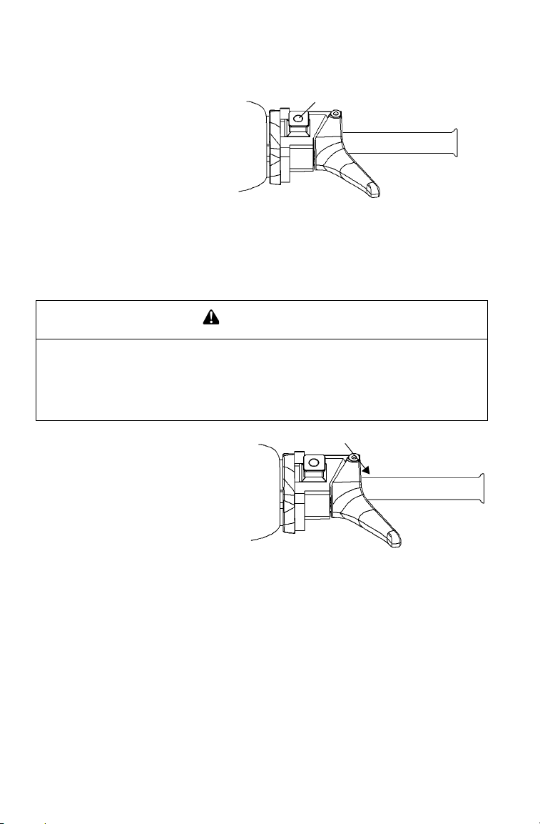
OPERATION
+
n Engine Stop Switch
Push down on the engine
stop switch (+) to
ground out the ignition
and stop the engine
quickly. Pull the switch
up to the ON position to
allow restarting.
n Throttle Safety Switch
The throttle safety switch is designed to stop the engine whenever all
pressure is removed from the throttle lever and the throttle cable or
valves do not return to the normal closed position.
WARNING
Operating the snowmobile with a faulty throttle safety switch can result in
serious injury or death in the event of an accident. If the throttle safety switch
does not shut off the engine during a carburetor/throttle system malfunction,
immediately push down the engine stop switch. Do not start the engine again
until the malfunction has been corrected by your dealer.
Test the throttle safety switch
system daily before operation.
1. Sit on the seat.
2. Start the engine and allow it
to idle.
3. Hold the throttle lever pin
stationary by exerting pressure on the pivot pin in the direction shown in the illustration.
4. Apply a slight amount of throttle. A properly functioning switch
must shut down the engine.
72
Page 76

OPERATION
Throttle Lever
WARNING
An improperly functioning throttle lever may cause erratic machine behavior
and loss of control, which could result in serious injury or death. If the throttle
lever does not work properly, DO NOT start the engine.
If the engine stops abruptly when the throttle lever is released:
1. Turn the ignition switch to OFF.
2. Visually inspect the throttle cable and carburetor/throttle body to
determine what caused the safety switch to activate.
3. Test the throttle lever by compressing and releasing it several times.
The lever and cable must return to the idle position quickly and
completely.
4. If the throttle lever operates properly, turn the ignition switch on and
go through normal starting procedures.
5. If the engine doesn't start, take the snowmobile to an authorized
Polaris dealer for service.
Excessive freeplay in the throttle cable may cause the safety switch to
activate, preventing the engine from starting. If this occurs, return the
machine to an authorized Polaris dealer for service.
If an emergency exists and it's necessary to start the engine, the throttle
safety switch and engine stop switch may be disconnected from the wire
harness. When these switches are disconnected, the ignition key switch
must be used to shut off the engine. DO NOT continue to operate the
machine with the throttle safety switch disconnected. Return the
machine to an authorized Polaris dealer for service as soon as possible.
73
Page 77

OPERATION
Emergency Stopping
The following chart lists methods for stopping the snowmobile in the
event of an emergency. See page 72 for more information about the
engine stop switch and throttle safety switch.
SYSTEM WHAT IT DOES
Ignition Switch Interrupts ignition circuit
Brake Slows jackshaft
Engine Stop Switch Interrupts ignition circuit
Throttle Safety Switch Interrupts ignition circuit
Tether Switch (Option) Interrupts ignition circuit
74
Page 78

OPERATION
Electronic Reverse (PERCt)
Electronic reverse will activate only if the engine RPM is below 4000.
WARNING
Improper reverse operation, even at low speeds, may cause loss of control,
resulting in serious injury or death. Damage will occur to the chaincase or
transmission if shifting is attempted when the engine is operating above idle
speed.
• Shift to or from reverse only when the snowmobile is stopped and when
engine speed is at idle.
• Look behind the vehicle before and while backing.
• Avoid sharp turns.
• Apply throttle slowly.
NOTICE: Engaging the starter when the engine is running WILL result in serious
engine damage, especially if the transmission is in reverse. Never
engage the starter when the engine is running.
75
Page 79

OPERATION
Electronic Reverse (PERCt)
Engaging Reverse
1. Stop the snowmobile and leave the engine idling.
2. Make sure the area behind your vehicle is clear.
3. Push the yellow reverse button on the left-hand control for one second, then release. The engine will automatically reduce RPM and
start a reverse rotation. A flashing reverse light on the instrument
panel will indicate that the transmission is in reverse.
4. Apply the throttle slowly to make sure the transmission is in
reverse.The maximum engine RPM will be 6000 when in reverse.
TIP: If the engine stops running, the snowmobile will be in forward gear when it's
restarted.
Disengaging Reverse
1. Stop the snowmobile and leave the engine idling.
NOTICE: Engaging the starter when the engine is running WILL result in serious
2. Push the yellow reverse button for one second and release. The
3. Apply the throttle slowly to make sure the transmission is in for-
engine damage, especially if the transmission is in reverse. Never
engage the starter when the engine is running.
engine will slow and begin to rotate forward. The light on the
instrument panel will shut off.
ward.
76
Page 80

OPERATION
Daily Storage
At the end of each ride, park the snowmobile on a level surface and support it at the
rear with an appropriate track stand. The
track should be suspended approximately
4I (10 cm) off the ground.
Remove the key and cover the machine.
To w i n g
Do not use the front bumper to pull or drag the snowmobile. The front
bumper is not designed for this type of use and may detach from the
vehicle if force is applied.
For your safety, do not attempt to use a tow hitch until you've read the
following warnings and understand the proper hitch functions.
WARNING
Objects towed with a rope have no braking power and can easily collide with
the rear of the snowmobile or other objects, resulting in serious injury or
death. DO NOT tow toboggans, sleds, saucers, or any type of vehicle with a
rope. Only a stiff metal pole connecting the towed object and the tow hitch on
the snowmobile should be used. If passengers are to be towed on a toboggan or sled, make sure the pole is at least four feet (1.2 meters) long to prevent any possibility of contact between the snowmobile's track and a person
riding in the towed object.
Braking distances increase when towing loads. Slow down to maintain control of the snowmobile.
If the snowmobile becomes inoperable and must be towed, and if it isn't
possible to use a rigid tow bar, attach the tow rope to the ski spindles
(not to the ski loops) to prevent damage to the steering components.
Remove the drive belt before towing, and have someone ride on the
towed snowmobile to operate the brake and steering when necessary.
NOTICE: Towing a disabled snowmobile with the drive belt in place can result in
serious damage to the engine and drive system. Always remove the
drive belt from a disabled snowmobile before towing.
77
Page 81

MAINTENANCE
Emission Control Information
Any qualified repair shop or qualified person may maintain, replace, or
repair the emission control devices or systems on your snowmobile.
Emission Control Label
Your snowmobile is equipped at the time of sale with an emission control information (ECI) label and a factory-installed emissions information hangtag. These items are required by U.S. Environmental
Protection Agency regulations. The ECI label is permanently affixed to
either the right side of the tunnel or the engine recoil cover. The ECI
label should not be removed, even after you purchase the snowmobile.
You may remove the factory-installed emissions information hangtag,
which is intended solely for your use in making a purchasing decision.
Emission Control Maintenance Requirements
Your snowmobile is certified to operate on gasoline with a minimum
octane level of 87 (R+M)/2. If your snowmobile is equipped with a
check engine light and it comes on, you must take your snowmobile to a
qualified dealer for diagnostic service. Specifications and adjustments
for engine tune-ups are located in the Service Manual, which is available to your qualified service technician. Reverse (if equipped) must not
be engaged during engine tune-ups.
Owner's Responsibilities
Please read the Snowmobile Engine Emissions Limited Warranty, and
read the maintenance section of your owner's manual. You are responsible for ensuring that the specified maintenance is performed. Polaris
recommends that you contact an authorized Polaris dealer to perform
any service that may be necessary.
78
Page 82

MAINTENANCE
Polaris Recommended Maintenance Program
To ensure many trouble-free miles of snowmobiling enjoyment, follow
recommended regular maintenance and perform service checks as outlined in this manual. Record maintenance and service in the Maintenance Log beginning on page 133.
The recommended maintenance schedule on your snowmobile calls for
service and maintenance inspections at 150 miles (240 km), 500 miles
(800 km) and 1000 miles (1600 km). These inspections should be performed by a qualified service technician. For continued optimum performance and component life, continue maintenance checks at 1000 mile
(1600 km) intervals.
All necessary replacement parts and labor incurred, with the exception
of authorized warranty repairs, become the responsibility of the registered owner. If, during the course of the warranty period, part failures
occur as a result of owner neglect in performing recommended regular
maintenance, the cost of repairs are the responsibility of the owner.
Personal safety is critical when attempting to service or make adjustments to your snowmobile. If you're not familiar with safe service or
adjustment procedures and the use of tools, or if you don't feel comfortable performing these tasks yourself, contact an authorized Polaris
dealer for service.
NOTICE: Hot components can cause damage to plastic. Always make sure the
exhaust system and engine have cooled before tipping the snowmobile on its side for service or inspection.
79
Page 83

MAINTENANCE
Periodic Maintenance Interval Table
The following chart is a guide based on average riding conditions. You
may need to increase frequency based on riding conditions. When
inspection reveals the need for replacement parts, always use genuine
Polaris parts, available from your Polaris dealer.
Item See
Clutch Alignment Offset
(without belt)
Drive Belt Condition 102 II II
Clutches 101 CCC
Belt Tension -- II II
Clutch Sheaves 101 II II
Engine Mounts -- II II
Recoil Rope -- II II
Engine Torque Stop 105 II II
Cylinder Head Bolts -- II I
Cylinder Base Nuts -- II I I
Ignition Timing BTDC -- II I
VES System -- CC C I
Coolant Level 91 IIRI
Coolant Hose -- II II
Heat Exchangers 93 II I I I
Coolant Circulation -- II I
Coolant Leaks -- II II
Spark Plug Condition 88 II IRI
Exhaust Pipe 94 II
Exhaust Retaining
Springs
I - Inspect (clean, adjust, tighten, lubricate, replace if necessary)
C - Clean R - Replace L - Lubricate
Page
150 mi.
(240 km)
101 II I
ENGINE/COOLING
94 II II
(800 km)
CLUTCH
500 mi.
Frequency
1000 mi.
(1600 km)
2000 mi.
(3200 km)
Pre-
Season
80
Page 84

MAINTENANCE
Periodic Maintenance Interval Table
Item See
Hose Routing -- II II
Hose Condition -- IIII
Fluid Leaks -- IIII
Brake Pads 96 II II
Brake Disc -- IIII
Parking Brakes 61 II II
Brake System 60, 96 I
Brake Fluid 97 R
Idle RPM -- II I
Throttle Lever 73 II I I I
Oil Pump Lever
(synchronize)
Throttle Cable 84 LLL
Throttle Position
Sensor
Fuel Lines 90 II I I I
Fuel Filter 90 RR
Oil Filter 89 RR
Oil Lines 89 III
Air Box -- II I II
Auxiliary Shut-Off
Switch
Throttle Safety Switch 72 II I I I
Ignition Switch -- II I I I
Taillight 64 II I I I
Brakelight 64 II I I I
Headlight 64 II I I I
Page
150 mi.
(240 km)
FUEL MANAGEMENT
-- II I
-- II I
ELECTRICAL
64 II I I I
(800 km)
BRAKES
500 mi.
Frequency
1000 mi.
(1600 km)
2000 mi.
(3200 km)
Pre-
Season
81
Page 85

MAINTENANCE
Periodic Maintenance Interval Table
Item See
Ski Toe Alignment -- II I
Suspension Mounting
Bolts
Steering Fasteners -- II I IC
Rear Suspension
Fasteners
Suspension Shock Oil -- II II
Cooling Fins and
Shroud
Drive Shaft Bearing 84 LL L I
Jackshaft Bearings 116 LL L I
Skags (Wear Bars) 113 II I II
Ski Saddle/Spindle
Bolts
Drive Chain Tension 95 II I I I
Hood Latches 63 II I I I
Rear Wheel Idler Bolts 109 II I I I
Idler Bolt Jam Nut 109 II I I I
Rear Suspension Pivot
Shafts
Steering Post U-Joint 83 LL L
Camber Alignment -- II I
Handlebar Centering -- I
Tether Switch and Strap 64 II I I I
Track Alignment 110 II I I I
Track Tension 108 III II
Front Limiter Strap -- II I I I
Rail Slide Condition 114 I
Chaincase Oil 85 II IRI
Page
150 mi.
(240 km)
-- II I I I
-- II I I I
-- II II
-- II I I I
83 LL L
500 mi.
(800 km)
CHASSIS
Frequency
1000 mi.
(1600 km)
2000 mi.
(3200 km)
Pre-
Season
I - Inspect (clean, adjust, tighten, lubricate, replace if necessary)
C - Clean R - Replace L - Lubricate
82
Page 86

MAINTENANCE
+
+
+
+
IQ 121 Shown
The Dragon SP rear suspension
has no grease points, it does
not require lubrication.
Lubrication
Rear Suspension
Lubricate the suspension pivot shafts with Polaris Premium All Season
Grease at the intervals outlined in the Periodic Maintenance Table
beginning on page 79 and before seasonal storage. When operating in
heavy, wet snow conditions, lubricate every 500 miles (800 km).
Lack of lubrication will adversely affect your ride and the life of the suspension. For more information about suspension lubrication and adjustments, see your Polaris dealer.
IQ 121/Switchback 136 Rear Suspension
83
Page 87

MAINTENANCE
+
+
Lubrication
Driveshaft Bearing
Inject grease into the fitting on the
speedometer sensor housing until
grease purges from the seal on the
inside of the tunnel. This should
take approximately two pumps. Do
not use more than four pumps.
Throttle Cable
Lubricate the throttle cable lightly
with grease or oil. With the engine
off, turn the handlebars to the left
and lubricate liberally as shown.
84
Page 88

Lubrication
1
3
2
n Chaincase Oil
Check the chaincase oil level at the
intervals outlined in the maintenance
charts beginning on page 79. The sight
glass (1) is located on the lower rear of
the chaincase. Maintain the oil level at
or slightly below the center of the sight
glass (2). Change the chaincase oil after
the first 500 miles (800 km), then every
1000 miles (1600 km) or seasonally.
Polaris recommends the use of Polaris
Synthetic Chaincase Lube. See page 118
for the part numbers of Polaris products.
Oil Check
1. Position the vehicle on a level surface.
2. View the oil level at the sight glass.
3. Remove the fill plug (3) and add the
recommended oil as needed. Do not
overfill.
4. Reinstall the fill plug, making sure it
is seated properly.
MAINTENANCE
85
Page 89

MAINTENANCE
4
Lubrication
Chaincase Oil
Oil Change
1. Position the vehicle on a level surface.
2. Remove the drain plug (4) and drain
the oil into a drain pan. Allow the oil
to drain completely.
3. Clean off all metal shavings from the
plug.
4. Install a new sealing washer on the
drain plug. The sealing surfaces on the drain plug and the oil tank
should be clean and free of burrs, nicks or scratches.
5. Reinstall the drain plug. Torque to 6-10 ft. lbs. (8-13 Nm).
6. Remove the fill plug. Clean off all metal shavings from the plug.
7. Add 11 oz. (325 ml) of the recommended oil. Do not overfill.
8. Reinstall the fill plug, making sure it is seated properly.
86
Page 90

MAINTENANCE
Spark Plugs
A new engine can cause temporary spark plug fouling due to the preservative added during the assembly process. Avoid prolonged idle speeds,
which cause plug fouling and carbonization.
Refer to your Owner's Manual Supplement for the specific spark plug to
be used in your machine.
Change the spark plugs every 2000-2500 miles (3200-4000 km).
• Use recommended spark plugs with the proper gap.
• Use only resistor-type spark plugs.
• Torque spark plugs to 18-22 ft. lbs. (24-30 Nm).
• Always carry spare spark plugs.
NOTICE: Using non-recommended spark plugs can result in serious engine
damage. A spark plug with a heat range too high will always cause
engine damage if the engine is operated in conditions more severe
than intended for that plug. Always use the spark plugs recommended
for your snowmobile. See your Owner’s Manual Supplement.
87
Page 91

MAINTENANCE
Spark Plug Condition
Spark plug condition is indicative of engine operation. The spark plug
firing end condition should be read after the engine has been warmed up
and the vehicle has been driven at higher speeds. Immediately check the
spark plug for correct color.
CAUTION
A hot exhaust system and engine can cause burns. Wear protective gloves
when removing a spark plug for inspection.
Normal
The normal insulator tip is gray, tan or light brown. There will be few
combustion deposits. The electrodes are not burned or eroded. This indicates the proper type and heat range for the engine and the service.
TIP: The tip should not be white. A white insulator tip indicates overheating,
caused by use of an improper spark plug or incorrect carburetor/throttle
body adjustments.
Wet Fouled
The wet fouled insulator tip is black. A damp oil film covers the firing
end. There may be a carbon layer over the entire nose. Generally, the
electrodes are not worn. General causes of fouling are excessive oil or
use of non-recommended injection oil.
88
Page 92

MAINTENANCE
Spark Plug Removal and Replacement
1. Remove the spark plug cap.
2. Using the special wrench provided in
the tool pouch, rotate the spark plug
counterclockwise to remove.
3. Reverse the procedure for spark plug
installation.
4. Torque to 18-22 ft. lbs. (24-30 Nm).
5. Reinstall the spark plug cap.
Oil Lines
Inspect oil line condition every 1000 miles (1600 km).
Oil Filter
The oil filter is located at the side of
the oil tank. Have your dealer change
the oil filter and bleed the system
annually or every 1000 miles (1600
km).
TIP: The direction of the arrows indicates
the direction of flow through the filter.
89
Page 93

MAINTENANCE
+
Intake Filters
The intake foam filters
limit snow ingestion into
the intake system. When
operating in loose powder
snow, check the foam filters periodically to remove
any accumulation of snow.
NOTICE: Operating the
Fuel Pump
All fuel pump service must be performed by an authorized Polaris
dealer. Do not attempt to service the fuel pump.
Fuel Filter/Fuel Lines
See your Polaris dealer for replacement of the fuel filter every 1000
miles (or annually).
Inspect the fuel lines regularly for signs of deterioration or damage.
Always check fuel line condition after periods of storage. Normal deterioration from weather and fuel compounds may occur. Replace worn or
damaged fuel lines promptly.
NOTICE: Kinking the fuel lines or using a pliers or similar tools to remove fuel
snowmobile with the intake filters removed may cause carburetor
icing. The result will be poor fuel economy or carburetor malfunction.
Always reinstall the intake filters before operating the snowmobile.
lines may cause damage to the lines. If a fuel line has been damaged
or kinked, replace it promptly.
90
Page 94

MAINTENANCE
Cooling System
Coolant
The coolant supplied in the system at the factory is a 50/50 mixture of
ethylene-glycol and distilled water, which will provide adequate freeze
protection under most conditions. If the vehicle will be stored or operated at extremely low temperatures, greater protection may be required.
Please see your Polaris dealer.
When adding or changing coolant, Polaris recommends using Premium
60/40 anti-freeze coolant, which is already premixed and ready to use.
Do not dilute with water. Never exceed a 60% antifreeze/40% water
mixture. See page 118 for Polaris products.
Never add tap water to the cooling system. Minerals cause deposits and
may react adversely with the metals in the engine and cooling system.
n Coolant Level
The engine coolant level is controlled by the recovery system. The
recovery system components are:
• Coolant bottle or overflow tank
• Engine filler neck
• Pressure cap
• Connecting hoses
Always maintain the coolant level between the minimum and maximum
marks on the coolant bottle (when engine is cold) to prevent overheating
and serious engine damage.
NOTICE: Operating the snowmobile with insufficient coolant will result in over-
heating and serious engine damage. Always maintain the coolant
level as recommended.
91
Page 95

MAINTENANCE
Cooling System
Coolant High Temperature Indicator Light
CAUTION
Steam and hot liquids will cause burns to your skin. Never remove the pressure cap when the engine is warm or hot.
The high temperature indicator light will illuminate when engine coolant temperature becomes too hot for safe continued operation of the
engine. If you must drive your machine after the high temperature indicator light has come on, drive slowly and stop frequently to allow the
engine to cool down. Driving in deep snow will also help cool the
engine. See your dealer for service.
Add coolant if the level is low. Engine performance will be reduced if
you continue operating when the high temperature light is on.
Flushing the Cooling System
To ensure that the coolant maintains its ability to protect the engine,
drain the system completely every two years and add a fresh mixture of
antifreeze and distilled water. This service must be performed when the
engine is cold. Ask your Polaris dealer to check the coolant when he
performs the fall tune-up on your snowmobile.
92
Page 96

MAINTENANCE
Cooling System
Bleeding the Cooling System
CAUTION
Steam and hot liquids will cause burns to your skin. Never bleed the cooling
system or remove the pressure cap when the engine is warm or hot.
Use of a non-standard pressure cap will not allow the recovery system to
function properly. If the pressure cap needs replacement, contact your
dealer for the correct part.
NOTICE: If coolant flow becomes restricted or plugged, coolant loss, air lock or
Perform the bleeding procedure when the engine is cold.
1. Position the vehicle so that the top of the tunnel is level. Elevate the
2. Remove the pressure cap and fill the coolant bottle with properly
3. Remove the bleed screw from the water outlet manifold and/or the
4. Add coolant to the coolant bottle to the maximum mark.
5. Start the engine and run at a fast idle for two to three minutes.
6. Stop the engine and check the coolant bottle level. Fill as required.
7. Feel the heat exchangers under the running boards. (On Switchback
8. Replace the pressure cap and carefully lower the front end of the
engine damage may result. Most cooling systems are equipped with a
filter that should be periodically inspected or replaced.
front of the vehicle slightly if necessary.
mixed coolant to the maximum mark.
thermostat housing. Allow the coolant to bleed through the system
until it runs out the bleed holes. Reinstall the bleed screw into the
manifold.
Loosen the bleed screw occasionally to purge any trapped air.
models, feel the tunnel gripper coolers on both sides.) If the system
is bled properly, they'll be warm to the touch. If they're not, repeat
step 5. Lift the front of the machine slightly to assist in the bleeding.
machine.
93
Page 97

MAINTENANCE
Exhaust System
Check the exhaust system for wear or damage at approximately 2000
miles (3200 km). Always allow the engine and exhaust system to cool
completely before inspecting.
CAUTION
Hot exhaust system parts can cause burns. Allow adequate time for the
exhaust system to cool. Never perform this procedure with the engine running.
1. Open the hood and inspect the muffler and pipes for cracks or damage.
2. Check for weak or missing retaining springs or damper/support
grommets.
3. Check for loose clamps on the pipe covers.
94
Page 98

Drive Chain Tension
11
2
Check drive chain tension weekly and
before each long trip. To obtain correct
chain tension:
1. Rotate the driven clutch counterclockwise to move all chain slack to
the tensioner side. Lock the brake
lever lock, or have an assistant hold
the brake lever firmly.
2. Loosen the adjuster bolt jam nut (1).
3. Finger tighten the adjuster bolt (2)
until it can no longer be adjusted by
hand, then back off 1/4 turn.
4. Tighten the jam nut while holding
the adjuster bolt. Torque to 21 ft.
lbs. (28 Nm).
5. Release the brake lever lock.
MAINTENANCE
95
Page 99

MAINTENANCE
2
1
3
Brakes
Hydraulic Brake Inspection
Inspect the brake lever reserve before each use of the snowmobile. See
page 60.
Brake pads must be replaced when the brake pad material becomes thinner than the backing plate (approximately 1/16I). A kit is available for
replacing brake pads. See your dealer.
WARNING
Brake failure during operation can result in serious injury or death. Properly
functioning brakes are vital to your safety. Be sure the brake pads do not
drag on the disc and that brake lever travel is not excessive.
Always replace brake pads when the brake pad material becomes thinner
than the backing plate (approximately 1/16
Brake Components
1. Brake Caliper
2. Brake Disc
3. Brake Pad Material
(Replace when thickness is
less than 1/16I/1.5 mm).
I).
Excessive Lever Travel
Hydraulic brakes are selfadjusting, but if excessive
brake pad clearance develops,
bring the machine to an authorized Polaris dealer for inspection and adjustment.
96
Page 100

MAINTENANCE
Brakes
Brake Fluid
The brake fluid level can be seen through a plastic sight glass in the
brake reservoir. If the fluid is sufficient, the sight glass will be black. If
the sight glass is any color other than black, add brake fluid.
Replace brake fluid at least every two years with Polaris DOT 4 high
temperature brake fluid. See page 118 for the part numbers of Polaris
products.
WARNING
After opening a bottle of brake fluid, always discard any unused portion.
Never store or use a partial bottle. Brake fluid is hygroscopic, meaning it rapidly absorbs moisture from the air. The moisture causes the boiling temperature of the brake fluid to drop, which can lead to early brake fade and the
possibility of accident or serious injury.
WARNING
Keep the master cylinder cover free of dirt and debris. The vent slits allow for
diaphragm movement, and if they become plugged, movement of brake fluid
below the diaphragm may be restricted, altering brake function.
NOTICE: Brake fluid will damage decals, paint and some plastics. Always wipe
up spills immediately.
97
 Loading...