

Page 1

2014 Owner's Manual for Maintenance and Safety
Read this manual carefully.
It contains important safety information.
Page 2

WARNING
Read, understand, and follow all of the
instructions and safety precautions in this
manual and on all product labels.
Failure to follow the safety precautions could
result in serious injury or death.
Page 3

1
Page 4

The following are registered trademarks of POLARIS Industries Inc.:
POLARIS® VICTORY® Global Electric Motorcars®
RANGER®GEM®e6®
Road America® is a trademark of Brickell Financial Services Motor Club, Inc.
Global Electric Motorcars® is a division of POLARIS.
Copyright 2013 POLARIS Sales Inc. All information contained within this publication is based on the latest
product information at the time of publication. Due to constant improvements in the design and quality of production components, some minor discrepancies may result between the actual vehicle and the information presented
in this publication. Depictions and/or procedures in this publication are intended for reference use only. No liability can be accepted for omissions or inaccuracies. Any reprinting or reuse of the depictions and/or procedures
contained within, whether whole or in part, is expressly prohibited.
Printed in U.S.A.
2014 GEM Owner’s Manual
P/N 9924946
2
Page 5

TABLE OF CONTENTS
Introduction. . . . . . . . . . . . . . . . . . . . . . . . . . . . . . . . . . . . . . . . . . . . . . . . . 6
Safety. . . . . . . . . . . . . . . . . . . . . . . . . . . . . . . . . . . . . . . . . . . . . . . . . . . . . 12
Features and Controls . . . . . . . . . . . . . . . . . . . . . . . . . . . . . . . . . . . . . . . 32
Operation. . . . . . . . . . . . . . . . . . . . . . . . . . . . . . . . . . . . . . . . . . . . . . . . . . 86
Maintenance . . . . . . . . . . . . . . . . . . . . . . . . . . . . . . . . . . . . . . . . . . . . . . . 96
Specifications . . . . . . . . . . . . . . . . . . . . . . . . . . . . . . . . . . . . . . . . . . . . . 134
Warranty . . . . . . . . . . . . . . . . . . . . . . . . . . . . . . . . . . . . . . . . . . . . . . . . . 140
Maintenance Log . . . . . . . . . . . . . . . . . . . . . . . . . . . . . . . . . . . . . . . . . . 150
Index . . . . . . . . . . . . . . . . . . . . . . . . . . . . . . . . . . . . . . . . . . . . . . . . . . . . 153
3
Page 6

WELCOME
Thank you for purchasing a GEM by POLARIS, and welcome to our world-wide POLARIS
family of recreational and utility vehicle owners. We believe POLARIS sets a standard of
excellence for all recreational and utility vehicles manufactured in the world today. With our
many years of experience in design and manufacturing, we proudly bring you only the finest
of vehicles:
• Snowmobiles
• All-terrain vehicles (ATVs)
• Low emission vehicles (LEVs)
• RANGER® utility vehicles
•RZR® sport vehicles
• VICTORY® motorcycles
• GEM® electric vehicles
4
Page 7

WELCOME
For safe and enjoyable operation of your vehicle, be sure to follow the instructions and recommendations in this owner’s manual. Your manual contains instructions for minor maintenance, but information about major repairs is outlined in the GEM Service Manual and
should be performed only by an authorized GEM dealer technician.
If questions arise after reading the manual, please contact GEM customer service. Be prepared to provide your Vehicle Identification Number (VIN) and date of purchase.
Your authorized GEM dealer knows your vehicle best and is interested in your total satisfaction. Be sure to return to your dealership for all of your service needs during, and after, the
warranty period.
GEM Customer Service
Phone: 855-RIDEGEM (855-743-3436)
Web: www.gemcar.com
5
Page 8

INTRODUCTION
This vehicle complies with the U.S. Department of Transportation National Highway T raf fic
Safety Administration (NHTSA) low-speed vehicle regulations and can be operated on many
streets posted with low speed limits. Please familiarize yourself with all laws and regulations
concerning the operation of the vehicle in your area.
This manual applies to the following GEM vehicles:
• GEM e2 (two-passenger)
• GEM e4 (four-passenger)
• GEM eS (two-passenger short-bed)
• GEM eL (two-passenger long-bed)
• GEM eL XD (two-passenger extra duty long-bed)
• GEM e6® (six-passenger)
6
Page 9

INTRODUCTION
Safety Signal Words and Symbols
The following signal words and symbols appear throughout this manual and on your vehicle.
Your safety is involved when these words and symbols are used. Become familiar with their
meanings before reading the manual.
NOTICE
The safety alert symbol indicates a potential
personal injury hazard.
WARNING
A WARNING indicates a hazardous situation
which, if not avoided, may result in death or
serious injury.
CAUTION
A CAUTION indicates a hazardous situation
which, if not avoided, may result in minor or
moderate injury.
A NOTICE indicates a situation that may result in
property damage.
The Prohibition Safety Sign indicates
an action NOT to take in order to avoid
a hazard.
The Mandatory Action Sign indicates
an action that NEEDS to be taken to
avoid a hazard.
7
Page 10

INTRODUCTION
WARNING
Failure to follow the warnings contained in this manual can result in severe injury or death.
Special precautions must be followed when owning and operating a battery-powered vehicle. This
vehicle is not a toy and can be hazardous to operate. This vehicle handles differently than other
vehicles. A collision or rollover can occur quickly, even during routine maneuvers, if you fail to take
proper precautions.
• Read this owner’s manual. Understand all safety warnings, precautions and operating procedures
before operating the vehicle. Keep this manual with the vehicle.
• This vehicle is an ADULT VEHICLE ONLY. NEVER operate this vehicle if you are under age 16 and
NEVER operate without a valid driver’s license.
• Never permit a guest to operate this vehicle unless the guest has read this manual and all product
labels.
• Operate this vehicle only on public or private roads where speed limits are appropriate for low speed
vehicles. Be familiar with motor vehicle laws in your area of operation. Do not operate this vehicle in
situations where it could become an obstacle or an annoyance for faster-moving traffic.
8
Page 11

INTRODUCTION
Manufacturer’s Label (Vehicle Information Label)
Record your vehicle's identification numbers and key number in the spaces provided on page
11.
The Vehicle Identification Number (VIN) is on the manufacturer’s label, located on the left
rear section of the roof panel. The VIN indicates the model year, model type and serial number of your vehicle. The manufacturer’s label also contains the Gross Vehicle W eight Rating
(GVWR) and Gross Axle Weight Rating (GAWR) information for your vehicle. Never
exceed the GVWR or the GAWR. See page 22.
To order an extra or replacement key for your vehicle, please contact GEM customer service.
See page 5. Be prepared to provide your key number and VIN.
9
Page 12

INTRODUCTION
Manufacturer’s
Label
VIN
GVWR
Information
Tire / Wheel Information
GAWR Information
Date of
Manufacture
USA Label EU Label
Manufacturer’s Label (Vehicle Information Label)
10
Page 13

INTRODUCTION
Manufacturer’s Label (Vehicle Information Label)
Vehicle Identification Number (VIN): |___|___|___|___|___|___|___|___|___|___|___|___|___|___|___|___|___|
Vehicle Model Number: _______________________________________________________________________
Motor Serial Number (on case of motor): __________________________________________________________
Key Number (stamped on key): _________________________________________________________________
Optional Rear Accessory # (stamped on key): ______________________________________________________
Date Purchased: _____________________________________________________________________________
11
Page 14

SAFETY
General Warning
Safety Labels and Locations
Warning labels have been placed on the vehicle for your protection. Read and follow the
instructions of the labels on the vehicle carefully. If any of the labels depicted in this manual
differ from the labels on your vehicle, always read and follow the instructions of the labels
on the vehicle.
If any label becomes illegible or comes off, contact your authorized GEM dealer to purchase
a replacement. Replacement safety labels are provided at no charge. The part number is
printed on the label.
General Warning
WARNING
• Read your owner’s manual before operating this vehicle.
• Do not operate this vehicle under the influen ce of alcohol,
• This vehicle is not intended to be driven at speeds exceeding
(continued on next page)
12
drugs or medication.
25 MPH (40 km/h).
Page 15

SAFETY
Safety Labels and Locations
General Warning
• Although most states prohibit this vehicle from operating on streets having posted speed li mits of
more than 35 MPH (56 km/h), state and local rules may vary. Check with your local law enforcement
(city and state officials) for variations in your area.
• Never exceed the passenger and cargo limits of this vehicle.
• Do not start or operate vehicle until all occupants are seated with seat belts fastened.
• Avoid sharp turns an inclines and at high speeds (may cause rollover).
• Reduce speed on wet and slippery surfaces and in turns.
• Do not leave children unattended in vehi cle.
• Set handbrake before leaving the vehicle.
• Remove key when leaving vehicle unattended.
• Stop vehicle before reversing direction.
• Be aware of small children and objects behind you before reversing direction.
• ALWAYS DRIVE SAFELY. FAILURE TO FOLLOW THESE WARNINGS COULD RESULT IN
SERIOUS OR FATAL INJURY.
13
Page 16

SAFETY
Safety Labels and Locations
Door/Seat Belt Warning
This label is located near the lower edge of the window on the driver’s side door on models
equipped with doors.
WARNING
The doors on this vehicle are designed only for protection against the elements. Do not rely on the
doors to contain occupants within the vehicle or to protect against injury during an accident.
WEAR SEAT BELTS AT ALL TIMES.
14
Page 17

SAFETY
Safety Labels and Locations
High Voltage Warning
High voltage warning labels are located in two places on your vehicle: near the battery compartment and under the hood near the motor controller.
WARNING
HIGH VOLTAGE
You could be seriou sly or fatally injured by electric shock if you attempt to open, repair,
test, inspect or adjust. Only qualified technicians should open and service. Consult service
manual.
15
Page 18

SAFETY
Safety Labels and Locations
Cargo Warning
Cargo warning labels are located in the beds of the following models.
WARNING
GEM eS: Maximum cargo capacity of this bed should never exceed 330 lbs. (149.7 kg). Distribute
weight equally over axle. No passengers permitted. Abuse or noncompliance will void warranty.
GEM e4S: Maximum cargo capacity of this bed should never exceed 250 lbs. (113.4 kg). Distribute
weight equally over axle. No passengers permitted. Abuse or noncompliance will void warranty.
GEM e6®S: Maximum cargo capacity of this bed should never exceed 440 lbs. (199.6 kg). Distribute
weight equally over axle. No passengers permitted. Abuse or noncompliance will void warranty.
GEM eL: Maximum cargo capacity of this bed should never exceed 700 lbs. (317.5 kg). Distribute
weight equally over axle. No passengers permitted. Abuse or noncompliance will void warranty.
GEM eL XD: Maximum cargo capacity of this bed should never exceed 1100 lbs. (499 kg). Distribute
weight equally over axle. No passengers permitted. Abuse or noncompliance will void warranty.
16
Page 19

Operator Safety
WARNING
Serious injury or death can result if you do not follow these instructions and procedures, which are
outlined in further detail within your owner's manual.
• Read this manual and all labels carefully.
Follow the operating procedures
described.
• Never allow anyone under age 16 to oper-
ate this vehicle and never allow anyone
without a valid driver's license to operate
this vehicle.
• Never permit a guest to operate this vehi-
cle unless the guest has read this manual
and all product labels.
• Always make sure the seat belts are
secured for operator and all passengers
before operating.
• Never exceed the maximum occupant
capacity of your vehicle:
GEM e2 2 occupants
GEM e4 4 occupants
GEM eS 2 occupants
GEM eL 2 occupants
GEM eL XD 2 occupants
®
GEM e6
6 occupants
SAFETY
17
Page 20

SAFETY
Operator Safety
• Never exceed the gross vehicle weight
rating (GVWR) of your vehicle.
• The cab frame is not designed or intended
to provide rollover protection. Avoid situations that could result in a rollover.
• Always be sure there are no obstacles or
people behind your vehicle when operating in reverse. When it's safe to proceed
in reverse, move slowly . Avoid turning at
sharp angles in reverse.
18
• Always use the proper size and type of
tires and always maintain proper tire
pressure as specified in this manual and
on safety labels.
• Never modify this vehicle through
improper installation or use of accessories.
Page 21

Operator Safety
• Never carry loads on the roof of the vehicle. Never exceed the stated load capacity
for this vehicle. Cargo should be properly
distributed and securely attached. Reduce
speed and follow the instructions on
cargo warning labels for hauling cargo.
Allow a greater distance for braking.
• Always set the park brake and remove the
key when leaving the vehicle unattended.
SAFETY
• The voltage in the battery pack is sufficient to cause death by electrocution.
With the exception of battery inspections
and refilling the water in flooded type
batteries, never attempt to perform service on the electric drive system, including the battery pack, unless you are
properly trained to work on electrical systems.
19
Page 22

SAFETY
Operator Safety
• Do not carry a passenger until you have at
least two hours of driving experience
with this vehicle.
• Always keep arms and legs inside the cab
frame while the vehicle is in motion.
• Always keep both hands on the steering
wheel and both feet on the floorboards of
the vehicle during operation.
• Never consume alcohol or drugs before
or while operating this vehicle.
20
• Never operate at excessive speeds.
Always travel at a speed proper for the
traffic, visibility and operating
conditions, and your experience.
• Never attempt jumps, doughnuts or other
stunts.
• Always inspect your vehicle each time
you use it to make sure it's in safe
operating condition. Always follow the
inspection and maintenance procedures
and schedules described in this manual.
Page 23

Operator Safety
• Never operate on excessively rough, slippery or loose terrain.
• Always follow proper procedures for
turning. Practice turning at slow speeds
before attempting to turn at faster speeds.
Never turn at excessive speeds.
• Always have this vehicle checked by an
authorized GEM dealer if it has been
involved in an accident.
SAFETY
• Always be alert for obstacles when operating this vehicle. Never attempt to operate over obstacles.
• Always be careful of skidding or sliding.
On slippery surfaces such as ice, travel
slowly and exercise caution to reduce the
chance of skidding or sliding out of control.
• Never operate this vehicle on steep hills.
21
Page 24

SAFETY
Operator Safety
Gross Vehicle Weight Rating (GVWR)
WARNING! Exceeding the gross vehicle weight rating of your vehicle can reduce stability and handling
and could cause loss of control. NEVER exceed the GVWR of your vehicle.
The maximum payload capacity of your vehicle is the maximum weight you may add to
your vehicle without exceeding the GVWR. This capacity is determined by calculating the
difference between your vehicle’s GVWR and wet weight.
Refer to the specification section of this manual or the Manufacturer’s Label on the vehicle
for model-specific information.
22
Page 25

SAFETY
Operator Safety
Gross Vehicle Weight Rating (GVWR)
When determining the weight you will be adding to your vehicle, and to ensure you do not
exceed the maximum payload capacity, include the following:
• operator body weight
• passenger body weight
• weight of all occupants’ apparel and items in or on apparel
• weight of any options or accessories and their contents
• weight of any additional cargo on the vehicle
23
Page 26

SAFETY
Operator Safety
Equipment Modifications
Never install any equipment or make vehicle modifications to increase the speed or power of
the vehicle. Any modifications to the original equipment of the vehicle create a substantial
safety hazard and increase the risk of bodily injury. The warranty on your vehicle is terminated if any equipment has been added to the vehicle, or if any modifications have been
made to the vehicle, that increase its speed or power.
The addition of certain accessories, including (but not limited to) mowers, blades, tires,
sprayers, or large racks, may change the handling characteristics of the vehicle. Use only
GEM-approved accessories, and familiarize yourself with their function and effect on the
vehicle.
24
Page 27

SAFETY
WARNING
Operator Safety
Failure to operate this vehicle properly can result in a collision, loss of control, accident or overturn,
which may result in serious injury or death. Heed all safety warnings outlined in this section of the
owner’s manual. See the OPERATION section of the owner’s manual for proper operating procedures.
Age Restrictions
This vehicle is an ADULT
VEHICLE ONL Y. NEVER
operate this vehicle if you
are under age 16 and
NEVER operate without a
valid driver’s license.
Seat Belts
Riding in this vehicle without wearing the seat
belt increases the risk of serious injury in the
event of an accident or sudden stop. Occupants
must wear seat belts at all times. Always make
sure the seat belts are secured for operator and
all passengers before operating. See page 71.
25
Page 28

SAFETY
Operator Safety
Operating Without Instruction
Operating this vehicle
without proper instruction
increases the risk of an
accident. The operator
must understand how to
operate the vehicle
properly in different
situations and on different
types of terrain. All
operators must read and
understand the Owner's Manual and all warning
and instruction labels before operating the
vehicle.
26
Ventilation When Charging Batteries
Failure to provide adequate ventilation while
charging batteries can result in an explosion.
Volatile hydrogen gas is emitted during charging
and may accumulate in pockets at the ceiling.
• Always ensure a minimum of 5 air changes per
hour in the charging area.
• Always remove any storage covers from the
vehicle and open any cab doors (if equipped)
before charging.
Page 29

Operator Safety
Failure to Inspect Before Operating
Failure to inspect and verify that the vehicle is in
safe operating condition before operating
increases the risk of an accident. Always inspect
the vehicle before each use to make sure it's in
safe operating condition. Always follow all
inspection and maintenance procedures and
schedules described in the owner's manual.
SAFETY
Using Alcohol or Drugs
Operating the vehicle after
consuming alcohol or drugs
could adversely affect
operator judgment, reaction
time, balance and
perception. Never drink
alcohol or use drugs or
medications before or while
operating this vehicle.
27
Page 30

SAFETY
Operator Safety
Operating a Damaged Vehicle
Operating a damaged vehicle can result in an
accident. After any overturn or accident, have
your authorized GEM dealer inspect the entire
machine for possible damage, including (but not
limited to) brakes, accelerator, steering system
and electrical system.
Operating at Excessive Speeds
Operating this vehicle at excessive speeds
increases the operator's risk of losing control.
Always operate at a speed that's appropriate for
the traffic, the visibility and operating conditions,
your skills and your passengers’ skills.
28
Exhibition Driving
Exhibition driving increases the risk of an
accident or overturn. Never attempt wheelies,
jumps, doughnuts or other stunts. Avoid
exhibition driving.
Page 31

Operator Safety
Turning Improperly
Turning improperly could cause loss of traction,
loss of control, accident or overturn. Always
follow proper procedures for turning. Never turn
abruptly or at sharp angles. Never turn at high
speeds. Practice turning at slow speeds before
attempting to turn at faster speeds.
Vehicle Rollover
Vehicle rollover could cause serious injury or
death. The cab frame is not designed or intended
to provide rollover protection. Always make sure
the seat belts are secured for operator and all
passengers before operating. Avoid situations
that could result in a rollover. Avoid sharp turns
and abrupt steering maneuvers.
SAFETY
Carrying Cargo
Carrying loads on the roof could damage the roof
and affect vehicle handling, which could result in
an accident or overturn. Never carry loads on the
roof of the vehicle.
29
Page 32

SAFETY
Operator Safety
Improper Tire Maintenance
Operating this vehicle with improper tires or with
improper or uneven tire pressure could cause
loss of control or accident. Always use the size
and type of tires specified for your vehicle.
Always maintain proper tire pressure as
described in the owner's manual and on safety
labels.
Unauthorized Use of the Vehicle
Leaving the keys in the vehicle can lead to
unauthorized use of the vehicle, which could
result in an accident or overturn. Always remove
the key when the vehicle is not in use.
30
Hot Drive Systems
The motor and controller are very hot during and
after use of the vehicle. Hot components can
cause burns and fire. Do not touch hot drive
system components. Always keep combustible
materials away from the drive system.
Page 33

Operator Safety
Precautions During Maintenance
WARNING! The voltage in the battery pack is
sufficient to cause death by electrocution. With
the exception of battery inspections and refilling
the water in flooded type batteries, never attempt
to perform service on the electric drive system,
including the battery pack, unless you are
properly trained to work on electrical systems.
WARNING! Do not work in or near the battery
compartment or on any other electrical
component of the vehicle while charging the
batteries. Always turn off the main disconnect
switch before servicing or unplugging any
electrical components. See page 52.
SAFETY
Always follow all safety instructions in the
maintenance portion of this owner’s manual, as
well as the following:
• Make sure the vehicle is properly immobilized
before beginning any maintenance.
• Always block the chassis securely before working under the vehicle.
• Turn the key off and remove it from the vehicle.
• Insulate any tools used within the battery area
to prevent sparks or battery explosion caused
by shorting the battery terminals or wiring.
Remove the batteries, or cover the exposed terminals with an insulating material.
FOR MORE INFORMATION ABOUT SAFETY
PLEASE CONTACT GEM CUSTOMER SERVICE.
See page 5.
31
Page 34

FEATURES AND CONTROLS
Trip/Odometer
Switch
Headlight
Switch
Turn Signal
Windshield Wiper
Horn Lever
Direction Switch
Key
Switch
LCD Display
Glove Box
Lock
Cup Holders
Instrument Pod
Storage Tray
Console
32
Page 35

Console
Electrical Access Panel
(Fuses/Main Disconnect Switch)
Optional Accessory Switches
HIGH
LOW
OFF
Headlight Switch
Press the top of the switch to turn the headlights to high
beam. Press the bottom of the switch to turn the headlights
to low beam. Move the switch to the center position to turn
the headlights off.
Electrical Components
Electrical wiring, circuit boards and components are
located under and behind the upper and lower console.
NOTICE: Liquids can damage electrical components and the
circuit board. Handle liquids with care. Do not spray
water directly into the upper or lower console.
FEATURES AND CONTROLS
33
Page 36

FEATURES AND CONTROLS
Key
ON
Key
OFF
Console
Key Switch
When the key is turned to the ON position (clockwise), the display will
light up and all electrical accessories can be used.
Leaving the key in the ON position will discharge the batteries. Always
turn the key to the OFF position when not operating. Remove the key
from the ignition to prevent unauthorized use.
When the key is turned to the OFF position, the vehicle will not accelerate, but accessories and lights will remain on for approximately 30 sec-
. Turn the key to the OFF position to disable all electrical circuits.
onds
The key can be removed from the switch when it is in the OFF position.
WARNING! Never turn the key to the OFF position while the vehicle is in motion. This could lead to
loss of speed control and loss of vehicle control, which could result in serious injury or death.
34
Page 37

FEATURES AND CONTROLS
Console
Zero Speed Detection Feature
To prevent the vehicle from rolling away, the electric motor will resist vehicle motion if the
accelerator pedal is released while the key is on and the vehicle is moving.
Horn
Press the turn signal wand inward toward the instrument pod to
sound the horn.
Glove Box
The glove box is equipped with a lock to protect items from theft or
damage. Use the ignition key to lock and unlock the glove box door.
Turn the key 1/4 turn counter-clockwise to unlock the door.
Horn
35
Page 38

FEATURES AND CONTROLS
Console
Turn Signal
The turn signal lever contains the controls for the turn signals, horn, windshield wiper and
windshield washer (if equipped). Check turn signal lamps before each ride. When driving,
activate a turn signal before turning to alert others of your intentions.
Tip: The key must be in the ON position to activate the turn signals.
Move the turn signal lever downward to signal a left turn. The left
turn signal lamp below the front headlight will flash.The left turn
indicator in the LCD display will also flash.
Move the lever upward to signal a right turn. The right signal
lamp and indicator will flash.
Return the lever to the center position to end the signal. If the
operator does not end the signal within 45 seconds, an alert will
sound.
36
Right Turn
Left Turn
Page 39

FEATURES AND CONTROLS
Console
Windshield Wiper
Push the turn signal lever toward the console and release it to
turn the windshield wipers on. Push the lever toward the console again to activate the washer momentarily (if equipped, see
page 85). Pull the lever toward the steering wheel to turn the
wiper off.
If the wiper fails to work, check for a blown fuse at the fuse
block. See page 102.
CAUTION! A worn or damaged wiper blade could impair operator vision and result in an accident. A
worn wiper blade could also damage windshield glass. Always replace worn or damaged wiper blades
promptly.
Wiper ON
Wiper OFF
37
Page 40

FEATURES AND CONTROLS
Console
Trip Meter/Odometer/E-Meter
The trip switch has four functions:
• Toggle between the odometer and trip meter.
• Reset the trip meter.
• Change the function of the speedometer and odometer from miles per hour (MPH) to kilometers per hour (km/h) and miles to kilometers.
• T oggle between odometer/trip meter and e-me ter to display accumulated power consumed
from grid, shown in kilowatt hours (kWh).
38
Page 41

FEATURES AND CONTROLS
Console
Trip Meter/Odometer/E-Meter
Trip Switch Operation
Desired Result Press Trip Switch
Toggle between the odometer and trip meter
modes on the display
Reset the trip meter to zero Press and hold for 3-9 seconds while display is in
Change the display from standard to metric (MPH
to km/h and miles to kilometers)
Display consumed power Press and release twice
Press and hold for less than 2 seconds
trip mode (“TRIP” is illuminated, see page 42)
Press and hold for 10-12 seconds while display is
in odometer mode
39
Page 42

FEATURES AND CONTROLS
Drive High
Drive Low
Reverse
Console
Direction Switch
NOTICE: Always bring the vehicle to a complete stop before
1. With the key in the ON position, apply the brakes.
2. Move the direction switch to the desired mode.
3. Release the brakes and gradually depress the accel-
CAUTION! Changing the direction switch position while driving could result in an automatic increase
or decrease in speed without a change to accelerator pedal pressure.
40
changing the position of the direction switch.
erator pedal to increase speed.
Page 43

FEATURES AND CONTROLS
Console
Direction Switch
Drive High
The HIGH mode allows operation of the vehicle at speeds of 0-25 MPH (0-40 km/h).
Drive Low
The LOW mode allows operation of the vehicle at speeds of 0-15 MPH (0-24 km/h). When
LOW mode is selected, the rate of acceleration is also limited.
Reverse
A reverse warning alert will automatically sound when the key is on and reverse mode is
selected. Vehicle speed is limited when operating in reverse. See page 90 for safe reverse
operation procedures.
41
Page 44
FEATURES AND CONTROLS
km
MILES
TRIP
BRAKE
km/h
MPH
Left Turn
Brake Warning
High Motor
Temperature Warning
Odometer/Trip Meter
Charger Connected
State of Charge/
Battery Discharge
Current Limiting Mode
Seat Belt Warning
Reverse
Selected
Drive Low
Selected
Drive High
Selected
Low Beam
Headlight
High Beam
Headlight
Service
Required
Right Turn
Speedometer/Service Code/Charge Display
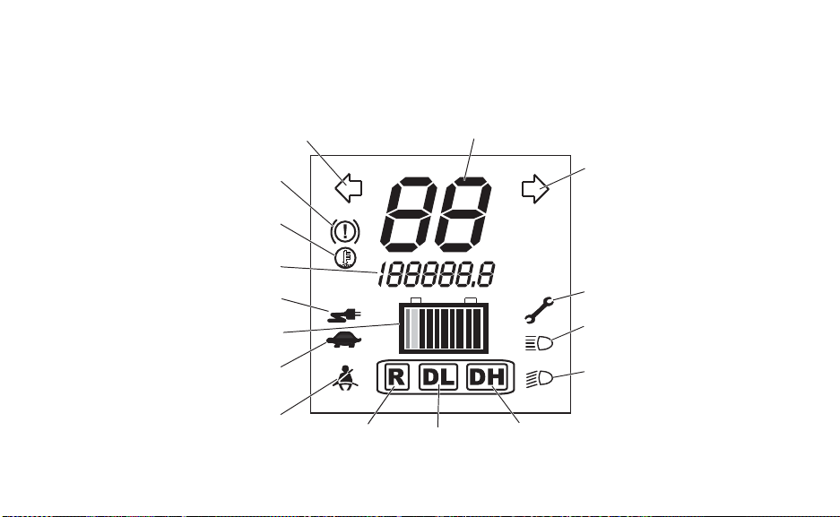
Console
LCD Display Indicators
42
Page 45

FEATURES AND CONTROLS
74% Charge
Console
LCD Display Indicators
Speedometer/Service Code/Charge Display Indicator
When driving, the speedometer displays vehicle speed in either miles per
hour (MPH) or kilometers per hour (km/h). The display can be changed to
display either standard or metric units of measurement. See page 38.
When the batteries are charging, this area displays the percent of charge.
When the service indicator illuminates, a service code displays in this
area.
43
Page 46

FEATURES AND CONTROLS
Console
LCD Display Indicators
Speedometer/Service Code/Charge Display Indicator
Common service codes are detailed below.
Code Condition Remedy
06 Accelerator pedal is depressed,
no direction is selected.
11 Accelerator pedal was depressed
before key was turned on.
15 Low state of charge on batteries. Charge batteries before
16 High state of charge on batteries. Turn headlights on for several
Tip: If any other codes display, contact your authorized GEM dealer or call GEM
customer service.
44
Release pedal, apply brakes,
make sure direction switch is
locked into a position.
Turn key off, release accelerator
pedal, then turn key on.
operating.
minutes, then turn the key switch
off and on.
Page 47

FEATURES AND CONTROLS
Console
LCD Display Indicators
Tu rn Indicators
The corresponding turn signal indicator flashes when a signal is activated.
Brake Warning Indicator
The brake warning illuminates when the park brake is engaged or when a brake system failure has occurred. If the brake warning illuminates, check the following
items before operating the vehicle.
Brake System Item Solution
Park brake Release the park brake.
Brake fluid level If low, add brake fluid. See page 98.
Brake system Check hoses for cracks, scuffs and worn spots. If you discover signs of
wear or damage, do not operate the vehicle. See your authorized GEM
dealer for service.
WARNING! Worn or damaged brake hoses can cause brake failure. Always have worn or damaged
brake hoses replaced promptly.
45
Page 48

FEATURES AND CONTROLS
Console
LCD Display Indicators
High Motor Temperature Warning Indicator
If the motor temperature warning illuminates, or if service code “41” displays in the
speedometer/service code display, the motor or motor controller may be overheat-
ing. Continued operation could result in motor damage. Stop the vehicle promptly,
preferably in a cool or shaded location, and wait for the motor to cool down. Do not operate
the vehicle until the warning indicator turns off.
Tip: Climbing steep grades while hauling heavy loads may overheat the motor or controller and shorten
component life.
46
Page 49

FEATURES AND CONTROLS
Console
LCD Display Indicators
Odometer/Trip Meter Indicator
The odometer indicator logs the total distance the vehicle has been driven since it was manufactured. The trip meter is useful for logging distances traveled on separate trips. See page 38
for trip meter instructions. The display can be changed to display either standard or metric
units of measurement. See page 38.
Charger Connected Indicator
This indicator illuminates approximately 8-10 seconds after the charger is
connected and remains on until the charger is disconnected. If the indicator fails to
illuminate when the charger is connected, the charger may not be charging. If this occurs,
make sure the main disconnect switch is in the ON position. See pages 61-65 for more
information about charging the batteries.
47
Page 50

FEATURES AND CONTROLS
Red
Yellow
Green
Console
LCD Display Indicators
State of Charge/Battery Discharge Indicator (BDI)
This indicator contains 8 green bars, a yellow bar and a red bar. It
shows available battery capacity by illuminating one or more bars.
The indicator illuminates when the key is turned on. It also illuminates 8-10 seconds after the charging cord is connected, turning off
when the batteries are 100% charged. To verify a full charge or to
check the state of charge, turn the key on.
As charge is depleted, bars begin to turn off from right to left.
Remaining bars indicate remaining battery charge. See page 49.
Tip: If only red and yellow bars are illuminated, charge is very low. Recharge as soon as possible. A full
recharge cycle (from one red bar to fully charged) may take 8 hours or more for a standard battery
pack, and up to 14 hours for a heavy duty battery pack.
48
Page 51

FEATURES AND CONTROLS
Console
LCD Display Indicators
State of Charge/Battery Discharge Indicator (BDI)
NOTICE: Batteries can be permanently
State of Charge/Battery Discharge
Indicator
Bars Color % Of Charge
1 Red (Far Left) Less Than 10
2 Yellow 10-20
3 Green 20-30
4 Green 30-40
5 Green 40-50
6 Green 50-60
7 Green 60-70
8 Green 70-80
9 Green 80-90
10 Green (Far Right) 90-100
damaged (and the warranty voided) if
allowed to remain 30 days or more
with low charge. Fully charge
batteries before storing. In hot
climates, battery self-discharge will
increase. In cold climates, batteries
could freeze if not properly charged. If
the vehicle will not be used for 10 or
more days, follow the battery storage
procedures on page 126.
49
Page 52

FEATURES AND CONTROLS
Console
LCD Display Indicators
Current Limiting Mode Indicator
This indicator illuminates if the system limits the amount of current available due to
extremely low battery voltage. The state-of-charge/battery-discharge indicator will
also indicate low voltage. If you continue to drive, acceleration and power will
begin to decrease. The controller will eventually shut down the vehicle to protect the batteries and motor from damage. If the state of charge is low and the current limiting indicator is
illuminated, stop the vehicle and recharge the batteries.
Seat Belt Warning
When the key is turned on, the seat belt warning illuminates for 45 seconds as a
reminder for occupants to fasten seat belts.
50
Page 53

Console
LCD Display Indicators
Direction Indicators
When the key is on, one of the three direction indicators illuminate to indicate the
selected position of the direction switch (REVERSE, DRIVE LOW or DRIVE
HIGH). See page 40.
Headlight Beam Indicators
Either the high beam or low beam headlight indicator illuminates to indicate which
headlight beam is selected. See page 33.
Service Required Indicator
When the service indicator illuminates, a service code displays in the speedometer/
service code display. See page 43 for common codes and descriptions.
FEATURES AND CONTROLS
51
Page 54

FEATURES AND CONTROLS
Main Disconnect
Switch
Fuses
Access Panel
Console
Main Disconnect Switch
WARNING! The main disconnect switch will disable
the vehicle by disconnecting the battery pack from the
motor. It does not disable the battery pack. HIGH
VOLTAGE will be present at the battery terminals.
HIGH BATTERY VOLTAGE IS ALWAYS PRESENT.
DO NOT TOUCH THE BATTERY TERMINALS.
The main disconnect switch is located inside the
fuse access panel on the lower console. The
main disconnect switch must be turned on for
operation and for charging.
52
Page 55

FEATURES AND CONTROLS
Hazard Switch
Console
Main Disconnect Switch
Move the switch to the left (OFF) to disconnect the battery pack from the motor. After the
switch is turned off, some power may remain in the system until all capacitors have discharged.
NOTICE: Do not turn off the disconnect switch while the vehicle is in motion or undergoing recharge
except in emergency situations.
NOTICE: Damage to electrical connections and components will occur if they are unplugged before
the main disconnect switch is turned off. Always turn off the main disconnect switch before
servicing or unplugging any electrical components.
Hazard Signals
Press the hazard signal switch to cause all turn signal lamps
to flash simultaneously. Use this feature to alert others of
an emergency or other situation requiring caution, especially if your vehicle becomes disabled on or near a road.
Press the switch again to cancel the hazard signals.
53
Page 56

FEATURES AND CONTROLS
Accelerator Pedal
Brake Pedal
Brake Pedal
The brake pedal is located on the floor to the left of the
accelerator pedal. Push the brake pedal toward the
floor to slow or stop the vehicle. Apply the brakes
before turning the key on.
WARNING! Constant brake use (riding the brakes) can
cause brakes to overheat and fail, which could lead to an
accident resulting in serious injury or death. Do not drive with
your foot resting or riding on the brake pedal.
54
Page 57

FEATURES AND CONTROLS
Accelerator Pedal
The accelerator pedal is located on the floor to the right of the brake pedal. To begin moving
or to increase vehicle speed, gradually push the accelerator pedal toward the floor. Holding
the accelerator pedal down continuously will accelerate the vehicle to the maximum speed.
The accelerator pedal will function only if the key is on.
To slow the vehicle, release the accelerator pedal. Electric motor braking provides braking
when the pedal is released. For additional speed control or to stop the vehicle, apply the
brakes.
55
Page 58
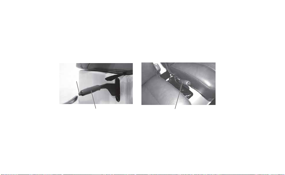
FEATURES AND CONTROLS
Park Brake Lever
WARNING! A rolling vehicle can cause serious injury. Always set the park brake when leaving the
vehicle unattended. Remove the key from the ignition to prevent unauthorized use.
NOTICE: Be sure the park brake is fully disengaged before driving. Failure to do so can lead to
overheating of the rear brakes.
Park Brake
Release
56
Park Brake Lever
GEM e2, eS, eL, eL XD
Park Brake Lever
GEM e4, e6®
Page 59

FEATURES AND CONTROLS
Park Brake Lever
The park brake lever is located to the lower right of the driver seat. To help prevent the vehicle from rolling, set the park brake when parking the vehicle. When the park brake is set and
the park brake indicator is illuminated, the vehicle will not move. Always apply the brakes
before setting or releasing the park brake.
The park brake is adjustable and should be checked periodically as outlined in the Periodic
Maintenance Chart beginning on page 96. See your authorized GEM dealer for service.
1. To set the park brake, apply the brakes. Pull the park brake lever upward as far as possible.
2. To release the park brake, apply the brakes. Press the park brake release inward and
move the lever downward as far as possible.
57
Page 60

FEATURES AND CONTROLS
8-Volt Gel
Battery
12-Volt Flooded
Battery
12-Volt Gel
Battery
Batteries
Battery Pack
Your vehicle is equipped with a battery pack containing either six 12-volt gel batteries, six 12-volt
flooded batteries or nine 8-volt gel batteries that
supply the power needed to operate the vehicle.
These batteries perform best when recharged fully
and often. Recharge the batteries daily, or after
each use of the vehicle.
NOTICE: Each vehicle is programmed at the factory for
58
a particular battery type. Switching battery
types should be done only by an authorized
GEM service technician.
Page 61

Batteries
Battery Performance Tips
• New batteries will not perform to their
fullest capacity until they have been discharged and recharged 20 to 30 times.
• Batteries should be fully charged before
the first use.
• Recharge the batteries daily , or after each
use of the vehicle.
• Always maintain a full charge on the bat-
teries. For best battery life, avoid discharging the batteries more than 80%.
See page 48.
FEATURES AND CONTROLS
• Batteries should be at room temperature
when recharging. Do not charge batteries
at temperatures of 110°F (43°C) or
higher.
• In the first few years of life, the batteries
should provide a range of up to 30 miles
(48 km) at 72°F (22°C). At 32°F (0°C)
range may be reduced to 12-15 miles (1924 km). Actual range my be affected by
road conditions, terrain, weather and
driving habits.
59
Page 62

FEATURES AND CONTROLS
Green Indicates
100% Charge
Batteries
On-Board Charger
The on-board battery charger is located under the hood and can be
viewed through the left front wheel well. When batteries are 100%
charged, a green light on the charger will illuminate.
When the vehicle will not be used for 10 or more days, leave the
main disconnect switch on and connect the charger. The on-board
battery charger will monitor the state of charge of the batteries and
automatically initiate a charge cycle whenever battery voltage falls
below a predetermined level. The on-board charger will maintain a
full battery charge for up to 24 weeks.
If the combined voltage of all batteries reaches 68 volts or less, a
safety feature in the on-board charger will not allow the charger to
activate. If this occurs, use the alternate charging method. See page 65.
60
Page 63

FEATURES AND CONTROLS
Batteries
Battery Charging
WARNING! Using a non-recommended extension cord could result in fire, heat damage or charger
failure, which could result in serious injury or death. Always use the recommended type of cord to
charge the batteries.
Tip: Do not use a ground fault interrupt (GFI) type cord on a GFCI-protected outlet.
WARNING! Charging from a circuit of lesser capacity and/or using a cord from the outlet to the vehicle
that is not sufficient in wire gauge could create a fire hazard.
WARNING! Failure to provide adequate ventilation while charging batteries can result in an explosion.
Hydrogen gas is emitted during charging and will rise and accumulate at the ceiling. Always ensure a
minimum of five (5) air changes per hour in the charging area. Never charge the batteries in an area
subject to a flame or spark, including areas containing gas or propane water heaters and furnaces. Do
not smoke in the charging area.
61
Page 64

FEATURES AND CONTROLS
Charge
Receptacle
Batteries
Battery Charging
The battery charge receptacle is located on the hood. When
charging the vehicle, always use a standard 3-wire grounded
extension cord of one of the following types:
• 12-gauge wire with 3-wire grounded, 50 feet (15.25 m) or
shorter.
• 14-gauge wire with 3-wire grounded, 25 feet (7.6 m) or
shorter.
62
Page 65

FEATURES AND CONTROLS
Batteries
Battery Charging
Always follow these precautions when charging:
• Position the vehicle on a level surface. Make sure the
charging area is well ventilated.
• Make sure the key is off.
• Always use the recommended extension cord type.
• Inspect the extension cord for cracks, loose connections
and frayed wiring. Never use a damaged extension cord.
• Always connect the charging cord to the vehicle’s charge
receptacle first, then plug the cord into a wall receptacle.
(continued on next page)
1. Plug into vehicle
2. Plug into outlet
63
Page 66

FEATURES AND CONTROLS
Batteries
Battery Charging
Tip: Always use a 110-volt AC, 15 amp breaker outlet. A GFI (Ground Fault Interrupt) receptacle is rec-
ommended. See your authorized GEM dealer if you do not have a GFI receptacle at your regular
recharge site.
• Make sure the charger uses a dedicated circuit to prevent overloading. If charging multiple
vehicles, each vehicle should use a dedicated circuit.
• When disconnecting the charger, always disconnect the extension cord from the wall
receptacle first, then disconnect the cord from the vehicle.
64
Page 67

FEATURES AND CONTROLS
Batteries
Alternate Battery Charging Method
If the combined voltage of all batteries reaches 68 volts or less, a safety feature in the onboard charger will not allow the charger to activate. Use the alternate char ging method to add
a small charge to each battery separately . The on-board char ger will then activate properly to
recharge all batteries to a full charge.
Use a 12-volt battery charger to charge 12-volt batteries. Charge each battery individually.
Use a 24-volt charger to charge 8-volt batteries. Charge in 3 groups, each consisting of 3
sequentially wired batteries.
Tip: It is not necessary to remove or disconnect battery post connections during the alternate charging
method.
65
Page 68

FEATURES AND CONTROLS
Batteries
Alternate Battery Charging Method
1. Turn the main disconnect switch off.
2. Set the battery charger to the medium amp setting (10 to 30 amps).
3. Charge each battery for 10-20 minutes.
4. Move quickly from battery to battery, as this is only a residual charge and it will dissi-
pate in a short period of time.
5. After charging the last battery, remove the off-board charger leads, turn the main discon-
nect switch on and plug the vehicle in.
6. If the on-board charger does not recognize the residual charge and activate, repeat the
alternate charging method.
66
Page 69

FEATURES AND CONTROLS
Batteries
Battery Handling Precautions
WARNING! Do not work in or near the battery compartment or on any other electrical component of
the vehicle while charging the batteries. Always turn off the main disconnect switch before servicing or
unplugging any electrical components. See page 52. The main disconnect switch will disable the
vehicle by disconnecting the battery pack from the motor. It does not disable the battery pack. HIGH
VOL TAGE will be present at the battery terminals. HIGH BATTERY VOLTAGE IS ALWAYS PRESENT.
DO NOT TOUCH THE BATTERY TERMINALS.
• Always make sure that all electrical accessories are grounded directly to the negative (-)
post on the terminal board. Never use the chassis or body as a ground connection.
• Make sure vent caps are installed properly and securely during vehicle operation and bat-
tery charging.
• Never connect a 12-volt accessory directly to the batteries. Always connect any powered
accessory to a 12-volt auxiliary outlet or terminal board.
(continued on next page)
67
Page 70

FEATURES AND CONTROLS
Dome Light Switch
Batteries
Battery Handling Precautions
• Never connect jumper cables to any of the batteries of this vehicle.
• Always wear safety glasses or approved eye protection when servicing the vehicle. Wear a
full-face shield and gloves when working with or around batteries and electrical connectors.
• Use only insulated tools when working in the battery compartment.
• Always keep battery terminals and connections clean and free of corrosion at all times.
See page 122.
Dome Light
Turn the dome light on or of f by pressing the switch on the side of
the light. The dome light is powered by four AA batteries. To
replace the batteries, remove the light cover and install the new
batteries. Instructions are located inside the battery compartment.
68
Page 71

FEATURES AND CONTROLS
Accessory Outlet
Accessory Outlet
The optional accessory outlet is located on the lower console,
to the right of the fuse access panel. This outlet will accept a
standard automotive 12-volt accessory and is intended for
moderately powered accessories, such as a cellular phone. It
will not operate large current items, such as cigarette lighters.
The fuse for the power outlet plug is located in the fuse block under the access panel in the
center of the lower console. Always use fuses with the same type and rating.
NOTICE: Do not plug in devices requiring power exceeding 25 watts. Damage to the vehicle electrical
system may occur or an accessory fuse may blow.
69
Page 72

FEATURES AND CONTROLS
Adjustment
Lever
Bench Seat Removal
Pull up on the front of the seat to disengage the front latches. Slide the seat forward and lift it
away from the seat base. To reinstall the seat, align the rear plunger to the socket at the rear
of the seat base. Slide the seat fully rearward, then push down firmly along the front edge of
the seat to secure the latches.
Seat Adjustment
The front seats on the GEM e4 and GEM e6® models are equipped
with manual seat adjustments. The seat adjustment lever is directly
under the front of the seat.
Move the adjustment lever to the left and slide the seat to the
desired position. Release the lever.
Make sure the seat latches securely in position. Test the latch by
attempting to slide the seat forward and rearward while seated.
70
Page 73

FEATURES AND CONTROLS
WARNING
Seat Belts
Failure to properly use seat belts and child restraints can result in serious injury or death. Always follow
all legal requirements for seat belt and child restraint use in on-road vehicles.
• Always make sure the seat belts are secured for operator and all passengers before operating.
• Pregnant women should wear the lap part of the belt across the thighs and as snug across the hips
as possible. Keep the belt low so that it does not come across the abdomen.
• The operator and all passengers are subject to the same legal requirements for seat belt use as
occupants in other on-road vehicles. Always make sure children are properly restrained. Children
ages 12 and under should ride in a rear seat. Infants must always be restrained in a rear seat. Use
the type of restraint that is correct for your child. When using child safety seats, always follow the
manufacturer’s instructions for proper installation and use in a vehicle containing only a shoulder/lap
belt restraint system. Visit www.seatcheck.org or call 1-866-SEATCHECK for more information
about child restraints.
71
Page 74
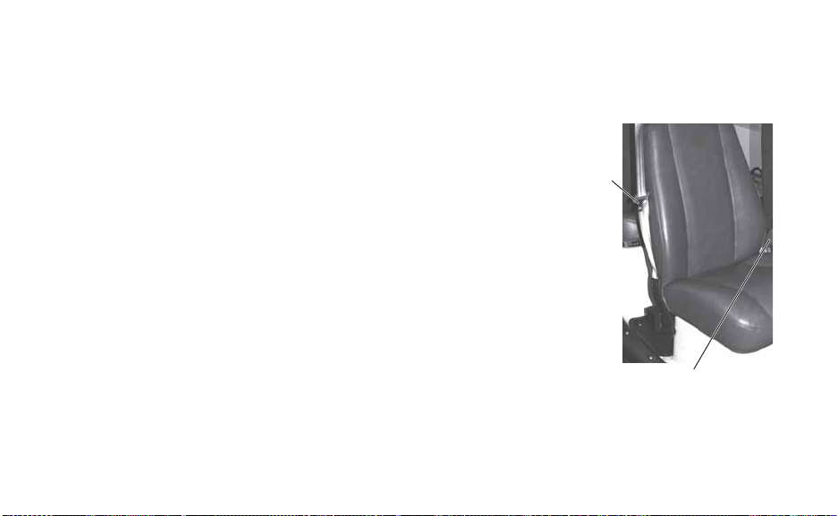
FEATURES AND CONTROLS
Seat Belts
Proper Seat Belt Use
This vehicle is equipped with three-point lap and diagonal seat belts for all occupants. Always make sure the
seat belts are secured for operator and all passengers
before operating. To wear the seat belt properly, follow
this procedure:
1. Pull the seat belt latch downward and across your
chest toward the buckle at the inner edge of the seat.
Slide the buckle up the webbing as far as needed for
the belt to reach across your hips. The belt should fit
snugly across your hips and diagonally across your
chest. Make sure the belt is not twisted.
72
Latch
Plate
Buckle
Page 75

FEATURES AND CONTROLS
Seat Belts
Proper Seat Belt Use
2. Push the latch plate into the buckle until it clicks.
3. Release the strap, it will self tighten.
4. To remove slack in the lap belt portion of the belt, pull upward on the shoulder belt. To
loosen the lap belt if it is too tight, tilt the buckle and pull the lap belt slightly longer.
5. To release the seat belt, press the square red button in the buckle's center. If necessary,
slide the buckle down the webbing to allow it to retract fully.
73
Page 76

FEATURES AND CONTROLS
Seat Belts
Seat Belt Safety Tips
• In a rear seat, you may have trouble tightening the lap/shoulder belt on the child restraint
because the buckle or latch plate is too close to the belt path opening on the restraint. Disconnect the latch plate from the buckle and twist the short buckle-end belt several times to
shorten it. Insert the latch plate into the buckle with the release button facing outward.
• If the belt still cannot be tightened when using a child safety seat, or if pulling and pushing
on the restraint loosens the belt, disconnect the latch plate from the buckle, turn the buckle
around and insert the latch plate into the buckle again. If you still cannot make the child
restraint secure, try a different seating position.
74
Page 77

FEATURES AND CONTROLS
Seat Belts
Seat Belt Inspection
Inspect all seat belts for proper operation before each use of the vehicle.
1. Push the latch plate into the buckle until it clicks. The latch plate must slide smoothly
into the buckle. A click indicates that it's securely latched.
2. Push the red release latch in the middle of the buckle to make sure it releases freely.
3. Pull each seat belt completely out and inspect the full length for any damage, including
cuts, wear, fraying or stiffness. If any damage is found, or if the seat belt does not operate properly , have the seat belt system checked and/or replaced by your authorized GEM
dealer.
4. To clean dirt or debris from the seat belts, sponge the straps with mild soap and water.
Do not use bleach, dye or household detergents.
75
Page 78

FEATURES AND CONTROLS
Stereo System (Option)
The optional stereo system is mounted in an overhead console and features speakers, FM radio, CD player and MP3 capabilities. Refer to
your stereo system’s user manual for detailed operating instructions.
76
Page 79

FEATURES AND CONTROLS
Latch Release
Handle
Trunk Cover Lock
TrunkBack
™
Rear Accessory Backs (Option)
Rear accessory back options are available. These rear accessory backs are interchangeable.
LinksBack
™
Clip-In StakeBack
™
77
Page 80

FEATURES AND CONTROLS
Rear Accessory Backs (Option)
WARNING! Never carry a passenger on a rear accessory back. Do not overload an accessory back.
Overloading the vehicle can reduce stability and handling and could cause loss of control. Never
exceed the GVWR or the GAWR. See page 22.
NOTICE: Use only GEM-approved rear accessories. Others may cause damage to the locking system
1. Remove the contents of the installed rear accessory back.
2. Ensure that the safety strap is secured.
CAUTION! Before releasing the rear latch, always make sure the safety strap is secure. The rear back
can fall suddenly and cause injury or damage to the vehicle if the safety strap is not secured.
3. Firmly grasp the installed back to prevent it from tipping or falling.
4. Use the ignition key to unlock the latch release handle.
Tip: There is a separate key for the TrunkBack™ cover lock.
78
or vehicle, and will void warranty.
Page 81

FEATURES AND CONTROLS
Rear Accessory Backs (Option)
5. Rotate the release handle to release the dual latches.
6. Remove the safety strap and carefully remove the existing accessory back.
7. Install the desired accessory back onto the mounting brackets.
8. Secure the safety strap.
9. Push the accessory back forward to engage the dual latches. Make sure you hear two
clicks, one for each latch engagement. Test to make sure the latches are secure. If not
secure, repeat this step.
CAUTION! Keep the rear latch in a locked position when operating or transporting th e vehicle. The
rear accessory could fall and cause injury if the safety strap is not used.
10. Always lock the release handle with the ignition key after changing accessory backs.
79
Page 82

FEATURES AND CONTROLS
Chrome Bumpers/Rugged Bumpers (Option)
Front bumpers are for appearance only and will protect the body
panels only from minor dents and scratches. They will not provide
protection to the vehicle in front collisions.
NOTICE: Never use your GEM vehicle for pushing. Damage to the
80
vehicle may result.
Page 83

FEATURES AND CONTROLS
Doors
WARNING! Doors do not offer structural protection in the event of an accident and do not change the
open body characteristics of the vehicle. The doors provide protection from the weather only. Always
use seat belts. Failure to use the seat belts puts the driver and passengers at greater risk of serious
injury or death in the event of an accident.
Soft Doors (Accessory): From either inside or outside the vehicle,
locate the zipper at the bottom front or mid rear of each door.
Unzip the door to open it. The door can be held in the open position using the straps and snaps located on the pillars or door supports.
Framed Canvas Doors (Option): To open the doors from outside
the vehicle, locate the door knob and slide it in the direction of the
arrows. To open doors from inside the vehicle, locate the nylon
strap at the center of the door and pull it toward the front of the
vehicle. To open windows, locate the zipper and unzip it to the
desired position. The window can be stored in the open position by
securing it with the nylon straps and snaps.
81
Page 84

FEATURES AND CONTROLS
Grab Handle Package (Option)
Grab handles can be added at each seat position to assist riders
in entering and exiting the vehicle. Interior grab handles are not
intended to retain passengers in the vehicle. Always make sure
the seat belts are secured for operator and all passengers before
operating.
Enclosed Cargo Carrier (Option)
To open the cargo carrier door, insert the key and turn the lock.
Pull the handle outward and rotate it to open the door. Reverse
the process to close and lock the door.
82
Page 85

FEATURES AND CONTROLS
Steering Column Lock (Option)
To lock the steering column, insert the key into the steering column
lock and turn it clockwise while turning the steering wheel. The wheel
may need to turn up to one full revolution. When you feel the lock
engage, remove the key.
WARNING! Do not leave the key in the column lock while driving as the lock
may inadvertently activate and cause loss of steering control, which could
result in serious injury or death.
To unlock the steering column, insert the key and turn the steering wheel to remove any pressure on the lock. Turn key counter-clockwise.
83
Page 86

FEATURES AND CONTROLS
Heater/Defogger/Fan
Switch
Deflector
Adjustable Tilt Steering Column (Option)
To adjust the tilt steering column, pull the lever at the left of
the column rearward toward the driver’s seat to release the
latch. Adjust the steering column to the desired position, then
push the lever toward the console to lock the steering column.
Heater/Defogger/Fan or Fan Only (Options)
The heater/defogger unit can be used to provide heat inside the
vehicle and to assist in defogging the windshield. The switch is
located on the console. Move the switch to the HEAT position,
then adjust airflow to the windshield as needed using the
deflectors located on the top of the console. Move the switch to
the FAN position to operate air flow without heat.
84
Tilt
Lever
Page 87

FEATURES AND CONTROLS
Windshield Washer (Option)
Push the turn signal lever toward the console to turn the windshield wipers on. Push the lever toward the console again to
activate the washer momentarily.
Check the washer reservoir fluid level frequently. When the
level is low, remove the cap and add windshield antifreeze
(not radiator antifreeze) rated for -25°F (-31°C). Operate the
system for a few seconds to flush out any residual water.
WARNING! Commercial windshield washer solvents are flammable.
Keep sparks, flames and cigarettes away. Handle with caution.
85
Page 88

OPERATION
WARNING
Failure to operate the vehicle properly can result in a collision, loss of control, accident or overturn,
which may result in serious injury or death. Read and understand all safety warnings outlined in the
safety section of this owner’s manual.
Pre-Ride Inspection
Failure to inspect and verify that the vehicle is in safe operating condition before operating
increases the risk of an accident. Always inspect the vehicle before each use to make sure it's
in safe operating condition.
Item Remarks Page
Accelerator Ensure proper operation 55
Brake system/pedal travel Ensure proper operation 98
Brake fluid Ensure proper level 98
Indicator lights/switches Ensure operation 42
Headlamp Check operation 109
Brake light/tail lamp Check operation 110
86
Page 89

OPERATION
Pre-Ride Inspection
Item Remarks Page
Turn signals Ensure operation of all signal lamps 36
Mirrors Adjust mirrors for proper side and rear view Horn Ensure operation 35
Seat belts Check length of belt for damage, check latches for proper
operation
Steering Ensure free operation 101
Tires Check tire condition and pressure 104-105
Latches (hood/seat) Ensure all latches are secure Batteries Ensure full charges, proper water levels, clean terminals 113-126
Battery cables Inspect for proper cable routing, secure connections 118
Wheels/fasteners Inspect, ensure fastener tightness 105
75
87
Page 90

OPERATION
Driving Procedure
1. Disconnect the charging cable. Make sure the main disconnect switch is on.
2. Sit in the driver's seat and fasten the seat belt. Make sure passengers are seated with seat
belts secured.
3. Adjust mirrors as needed.
4. Turn the key clockwise to the ON position.
5. Apply the brakes.
6. Release the park brake.
7. Move the direction switch to the desired position. See page 40.
8. Check your surroundings and determine your path of travel.
9. Keeping both hands on the steering wheel, release the brake pedal and gradually push
the accelerator toward the floor to begin driving.
10. Drive slowly. Practice maneuvering and using the accelerator and brakes on level surfaces.
88
Page 91

OPERATION
Driving Procedure
11. Before turning, activate a turn signal to alert others of your intentions. See page 36.
12. Do not carry a passenger until you have at least two hours of driving experience with this
vehicle. Allow a passenger to ride only in a designated passenger seat with seat belt
secured.
13. To stop the vehicle, release the accelerator pedal completely and brake to a complete
stop.
NOTICE: Always bring the vehicle to a complete stop before changing the position of the direction
14. Set the park brake.
WARNING! A rolling vehicle can cause serious injury or death. Always set the park brake when leaving
the vehicle unattended.
15. Turn the key off.
16. Recharge the batteries daily, or after each use of the vehicle.
switch.
89
Page 92

OPERATION
Driving in Reverse
Follow these precautions when operating in reverse:
1. Always check for obstacles or people behind the vehicle. Always inspect left and right
fields of vision before backing.
2. Avoid backing downhill.
3. Back slowly.
4. Apply the brakes lightly for stopping.
5. Avoid turning at sharp angles.
6. Never accelerate suddenly.
90
Page 93
OPERATION
WARNING
Sideways
skid
Turn in direction
of skid
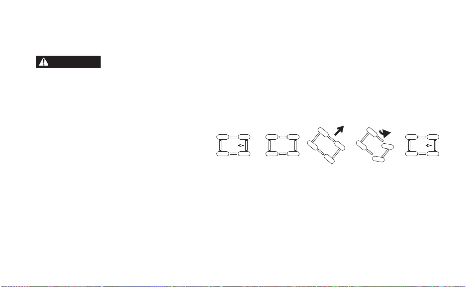
Driving On Slippery Surfaces
Skidding or sliding can cause loss of control or overturn (if tires regain traction unexpectedly). When
operating on slippery surfaces, reduce speed and use extra caution to reduce the chance of skidding or
sliding out of control. Do not operate on excessively slippery surfaces.
Whenever driving on slippery surfaces
such as wet or icy pavement or loose
gravel, follow these precautions:
1. Do not operate on excessively slippery surfaces.
2. Slow down before driving onto a
slippery surface.
3. Avoid quick, sharp turns, which can cause skids.
4. Correct a skid by turning the steering wheel in the direction of the skid. Never apply the
brakes during a skid.
91
Page 94

OPERATION
Parking the Vehicle
1. Apply the brakes. Stop the vehicle on a level surface.
2. When parking inside a garage or other structure, be sure that the structure is well ventilated and that the vehicle is not close to any source of flame or sparks, including any
appliance with pilot lights.
3. Place the direction switch on either forward position.
4. Set the park brake.
5. Turn the key off. Remove the key from the ignition to prevent unauthorized use.
92
Page 95

OPERATION
Parking on an Incline
Avoid parking on an incline if possible. If it's unavoidable, follow these precautions:
• If parking in an open area, block the wheels on the downhill side of the vehicle after turning the key off.
• If parking parallel to a curb, stop the vehicle close to the curb. If the vehicle is facing
downhill, turn the steering wheel toward the curb. The forward part of the front tire should
be turned into the curb. If the vehicle is facing uphill, turn the steering wheel away from
the curb. The rear part of the front tire should be turned into the curb.
• Set the park brake.
93
Page 96

OPERATION
Transporting the Vehicle
NOTICE: Towing your GEM vehicle could result in severe damage to the vehicle . Vehicle failures
When transporting the GEM vehicle on a trailer, always use a trailer with an approved load
rating greater than the GEM vehicle’s curb weight plus any installed accessories or cargo.
Refer to the specifications section beginning on page 134.
Always tie the frame of the GEM vehicle to the transporting unit securely with suitable
straps. Always secure the straps to the front sub-frame and the rear axle of the GEM vehicle.
Never place tie straps across any plastic body or floor panel components.
(continued on next page)
94
resulting from dolly towing will void warranty.
Page 97

OPERATION
Transporting the Vehicle
Transport the vehicle in a closed trailer if possible. Use the following guidelines when transporting the vehicle on an open trailer.
1. Always transport the GEM vehicle facing forward on the trailer.
2. Set the park brake.
3. Remove the key to prevent loss.
4. Secure the seats, hood and any items that could be damaged or dislodged by strong
winds. If equipped with hard doors, put all windows down.
5. Never allow passengers on a trailer or in a trailered vehicle.
6. Reduce speed and drive with caution.
95
Page 98

MAINTENANCE
Periodic Maintenance Chart
WARNING! Always wear safety glasses or approved eye protection when servicing the vehicle. Wear
a full-face shield and gloves when working with or around batteries and electrical connectors. Always
use insulated tools when working with or near batteries. Failure to follow these instructions could result
in serious injury or death.
NOTICE: Damage to electrical connections and components will occur if they are unplugged before
Careful periodic maintenance will help keep your vehicle in the safest, most reliable condition. Inspect, clean, lubricate, adjust and replace parts as necessary . When inspection reveals
the need for replacement parts, always use genuine GEM parts available from your authorized GEM dealer. Record maintenance and service in the Maintenance Log beginning on
page 150.
Tip: Service and adjustments are important for proper vehicle operation. If you're not familiar with safe
96
the main disconnect switch is turned off. Always turn off the main disconnect switch before
servicing or unplugging any electrical components.
service and adjustment procedures, have your authorized GEM dealer perform these operations.
Page 99

MAINTENANCE
Periodic Maintenance Chart
Monthly Maintenance See Page
Check battery fluid level (flooded only) 119
Wash tops and terminals of batteries and allow to dry 122
Check cables and terminal connections 123
Check for worn insulation or frayed wires 123
Check battery hold-down bar to ensure batteries are tightly secured 123
Check tires for correct air pressure and wear 104
Check brake fluid reservoir for proper brake fluid level. 98
Check brake lines for leaks. -Check seat belts for proper operation 75
Check headlights, horn, turn signals, windshield wiper and brake lights for proper
operation.
Check steering wheel freeplay 101
--
97
Page 100

MAINTENANCE
Brakes
Brake Fluid
Inspect the brake system routinely. Inspect the brake fluid level before each operation. If the
level drops between fluid checks, add brake fluid as needed. See your authorized GEM
dealer for service.
WARNING! After opening a bottle of brake fluid, always discard any unused portion. Never store or
use a partial bottle. Brake fluid is hygroscopic, meaning it rapidly absorbs moisture from the air. The
moisture causes the boiling temperature of the brake fluid to drop, which can lead to early brake fade
and the possibility of accident or severe injury.
Change the brake fluid every two years and any time the fluid becomes contaminated, the
fluid level is below the minimum, or if the type and brand of the fluid in the reservoir are
unknown. Always use DOT4 brake fluid.
98
 Loading...