

Page 1

SPECIFICATIONS
CHAPTER 1
SPECIFICATIONS
340 CLASSIC. . . . . . . . . . . . . . . . . . . . . . . . . . . . . . . . . . . . . . . . . . . . . . . . . . . . . . . . .1.2
500 CLASSIC. . . . . . . . . . . . . . . . . . . . . . . . . . . . . . . . . . . . . . . . . . . . . . . . . . . . . . . . .1.4
550 CLASSIC. . . . . . . . . . . . . . . . . . . . . . . . . . . . . . . . . . . . . . . . . . . . . . . . . . . . . . . . .1.6
600 CLASSIC. . . . . . . . . . . . . . . . . . . . . . . . . . . . . . . . . . . . . . . . . . . . . . . . . . . . . . . . .1.8
700 CLASSIC. . . . . . . . . . . . . . . . . . . . . . . . . . . . . . . . . . . . . . . . . . . . . . . . . . . . . . . .1.10
500 INDY . . . . . . . . . . . . . . . . . . . . . . . . . . . . . . . . . . . . . . . . . . . . . . . . . . . . . . . . . . . 1.12
SUPERSPORT. . . . . . . . . . . . . . . . . . . . . . . . . . . . . . . . . . . . . . . . . . . . . . . . . . . . . . . 1.14
340 INDY TOURING . . . . . . . . . . . . . . . . . . . . . . . . . . . . . . . . . . . . . . . . . . . . . . . . . .1.16
TRAIL TOURING . . . . . . . . . . . . . . . . . . . . . . . . . . . . . . . . . . . . . . . . . . . . . . . . . . . . . 1.18
600 EDGE TOURING. . . . . . . . . . . . . . . . . . . . . . . . . . . . . . . . . . . . . . . . . . . . . . . . . . 1.20
700 TOURING . . . . . . . . . . . . . . . . . . . . . . . . . . . . . . . . . . . . . . . . . . . . . . . . . . . . . . .1.22
WIDETRAK LX. . . . . . . . . . . . . . . . . . . . . . . . . . . . . . . . . . . . . . . . . . . . . . . . . . . . . . . 1.24
500 XC SP . . . . . . . . . . . . . . . . . . . . . . . . . . . . . . . . . . . . . . . . . . . . . . . . . . . . . . . . . .1.26
600 HO STANDARD FUSION . . . . . . . . . . . . . . . . . . . . . . . . . . . . . . . . . . . . . . . . . . . 1.28
600 HO DRAGON FUSION . . . . . . . . . . . . . . . . . . . . . . . . . . . . . . . . . . . . . . . . . . . . . 1.30
700 FUSION. . . . . . . . . . . . . . . . . . . . . . . . . . . . . . . . . . . . . . . . . . . . . . . . . . . . . . . . . 1.32
900 FUSION. . . . . . . . . . . . . . . . . . . . . . . . . . . . . . . . . . . . . . . . . . . . . . . . . . . . . . . . . 1.34
600 HO SWITCHBACK . . . . . . . . . . . . . . . . . . . . . . . . . . . . . . . . . . . . . . . . . . . . . . . . 1.36
900 SWITCHBACK . . . . . . . . . . . . . . . . . . . . . . . . . . . . . . . . . . . . . . . . . . . . . . . . . . . 1.38
TRAIL RMK . . . . . . . . . . . . . . . . . . . . . . . . . . . . . . . . . . . . . . . . . . . . . . . . . . . . . . . . . 1.40
600 HO RMK . . . . . . . . . . . . . . . . . . . . . . . . . . . . . . . . . . . . . . . . . . . . . . . . . . . . . . . . 1.42
700 RMK . . . . . . . . . . . . . . . . . . . . . . . . . . . . . . . . . . . . . . . . . . . . . . . . . . . . . . . . . . . 1.44
900 RMK . . . . . . . . . . . . . . . . . . . . . . . . . . . . . . . . . . . . . . . . . . . . . . . . . . . . . . . . . . . 1.46
1
1.1
Page 2

SPECIFICATIONS
340 CLASSIC
MODEL S06ND3AS
Table 1-1: Engine
Engine type Fuji
Engine displacement 339cc
Bore in/mm 2.45/62.3
Stroke in/mm 2.19/55.6
Piston to cylinder clearance in/
mm
Piston ring end gap .008-.014/.20-.35
Operating RPM±200 7000
Idle RPM±200 1600
Clutch engagement RPM ±200 4100
Table 1-2: Fuel Delivery
Typ e VM 30 SS
Main Jet 170
Pilot Jet 35
Jet Needle/Clip position 5DP13/3
Needle Jet O-6 (169)
Throttle gap under cutaway
in/mm
Throttle slide cutaway 2.5AL
Valve seat 1.5Viton
Starter jet 1.5
Pilot air jet 2.5
Fuel screw setting N/A
Air screw setting 1.5
Recommended fuel octane
(R+M/2)
.003-.005/.076-.127
.240/6.1
87 NonOxy/89 Oxy Min
Table 1-3: Jetting
Ambient Temperature
Altitude
meters
(feet)
< -25_F/<-35_C
0_F to +20_F/-18_C to -7_C
+15_F to +35_F/-9_C to +2_C
+30_F to +50_F/-1_C to +10_C
0-600
(0-2000)
600-1200
(2000-4000)
1200-1800
(4000-6000)
1800-2400
(6000-8000)
2400-3000
(8000-10000)
3000-3700
(10000-12000)
-15_F to +5_F/-26_C to -15_C
-30_F to -10_F/-34_C to -23_C
185#4180#3170#3170#3165#3160#3155#3150
175#3170#3160#3160#3155#3150#3140#2140
165#3160#3155#3150#3145#3140#2130#2130
155#3150#3140#3135#3135#2130#2120#1120
145#3140#3130#2130#2125#2120#1110#1110
135#3130#2120#2115#2115#1110#1100#1100
Table 1-4: Clutching
Altitude meters
(feet)
0-900
(0-3000)
900-1800
(3000-6000)
1800-2700
(6000-9000)
2700-3700
(9000-12000)
Drive Clutch (P-85) Driven Clutch (TEAM)
Shift
Wei gh t
10
10-M
Blue
10MW
10MR
Clutch
Spring
Black-
Black-
Black-
Black-
2287
2287
2287
2287
Clutch
Spring
Red/
Black
Red/
Black
Red/
Black
Red/
Black
Driven
Helix
S36ER 16:41-72
S36ER 16:41-72
S36ER 16:41-72
S36ER 16:41-72
Drive clutch bolt torque 50 ft-lbs(69Nm)
Table 1-5: Belt
Belt part number 3211078
Belt width in/cm 1.438/3.65
Belt side angle 28_
Outside diameter in/cm 46.625/118.4
Clutch center distance in/cm 11.5/29.2
>+60_F/>+16_C
+45_F to +65_F/+7_C to +18_C
#3
#2
#2
#1
#1
#1
Gearing
1.2
Table 1-6: Chaincase
Center distance in/cm 7.92/20.1
Reverse type PERC
Page 3

SPECIFICATIONS
Table 1-7: Fluids and capacities
Fuel gal/l 11.8/44.7
Oil qts/l 3.25/3.1
Coolant qts/l N/A
Chaincase oz/ml 9/266.2
Brake fluid type DOT4
Table 1-8: Track
Width in/cm 15/38
Length in/cm 121/307
Lug height in/cm .82/2.1
Track tension sag in/cm with
10 lbs/4.54kg placed 16 in/
40.6cm ahead of rear idler
shaft
.375-.5/1-1.3
Table 1-9: Front Suspension
Suspension type Edge
IFS shocks Arvin/7041932
IFS spring rate
lbs-in/kg-mm
IFS Spring pre-load in/mm .625/16
Front vertical travel in/cm 10/25.4
Ski center distance in/cm 42.5/108
Camber in/mm .59±.31/15.0±7.9
Toe in/mm .12-.25/3.0-6.35
100/1.79
Table 1-12: Dimensions
Width in/cm 48/122
Length in/cm 113/287
Height in/cm 48/122
Est dry weight lb/kg 517/234.7
Table 1-13: Electrical
Ignition timing 26.5_@3000RPM
Spark plug gap in/mm .028/.71
Spark plug NGK BR8ES
Voltage regulator/output 240watt
Magneto pulse 6
CDI marking CU7245
Table 1-10: Rear Suspension
Suspension type Edge
Front track shock (FTS) Arvin/7041939
FTS Spring Rate
lbs-in/kg-mm
FTS pre-load Fixed
Rear track shock Fox/7042120*
Rear travel in/cm 13.9/35.3
* notes that shock is rebuildable
200/3.58
Table 1-11: Torsion spring
Torsion spring PNs
(LH/RH)
Torsion spring diameter in/mm .359/9.12
Torsion spring tail angle 77_
7041629/7041630
1.3
Page 4

SPECIFICATIONS
500 CLASSIC
MODEL S06ND4BS
Table 1-14: Engine
Engine type Fuji
Engine displacement 488cc
Bore in/mm 2.83/72
Stroke in/mm 2.36/60
Piston to cylinder clearance in/
mm
Piston ring end gap .0079-.016/.20-.40
Operating RPM±200 7800
Idle RPM 1600
Clutch engagement RPM ±200 4000
Table 1-15: Fuel Delivery
Typ e TM 38
Main Jet 360
Pilot Jet 40
Jet Needle/Clip position 9DFY1-54/2
Needle Jet P-2(825)
Throttle gap under cutaway
in/mm
Throttle slide cutaway 2
Valve seat 1.5 Viton
Starter jet 145
Pilot air jet 0.9
Fuel screw setting 1.5
Air screw setting N/A
Recommended fuel octane
(R+M/2)
.0035-.0049/.090-.125
.078/2.0
Min 87 NonOxy/89 Oxy
Min
Table 1-16: Jetting
Ambient Temperature
Altitude
meters
(feet)
< -30_F/<-34_C
+10_F to +30_F/-12_C to -1_C
+30_F to +50_F/-1_C to +10_C
0-600
(0-2000)
600-1200
(2000-4000)
1200-1800
(4000-6000)
1800-2400
(6000-8000)
2400-3000
(8000-10000)
3000-3700
(10000-12000)
-10_F to +10_F/-23_C to -12_C
-30_F to +10_F/-34_C to -23_C
390#4370#3360#3360#2340#2320
370#3350#3340#2320#2310#2300
350#3330#3320#2300#2290#2270
320#3310#3300#2380#2370#1250
300#3290#2270#2260#1240#1230
280#2270#2250#1240#1220#1210
Table 1-17: Clutching
Altitude meters
(feet)
0-900
(0-3000)
900-1800
(3000-6000)
1800-2700
(6000-9000)
2700-3700
(9000-12000)
Drive Clutch (P-85) Driven Clutch (P-85)
Shift
Blue
Clutch
Spring
Blue/
White
Blue/
White
Wei gh t
10-M5 Gold Black
10-M
10 MW
10M Red
Clutch
Spring
Gold Black
Dark
Dark
Black
Black
Driven
Helix
36 D
Button #2
36 D
Button #2
36 D
Button #2
36 D
Button #2
Drive clutch bolt torque 50 ft-lbs(69Nm)
Table 1-18: Belt
Belt part number 3211078
Belt width in/cm 1.438/3.65
Belt side angle 28_
Outside diameter in/cm 46.625/118.4
Clutch center distance in/cm 11.5/29.2
>50_F />+10_C
#2
#2
#1
#1
#1
#1
Gearing
21:40-74
21:40-74
21:40-74
21:40-74
1.4
Table 1-19: Chaincase
Center distance in/cm 7.92/20.1
Reverse type Mechanical
Page 5
SPECIFICATIONS
Table 1-20: Fluids and capacities
Fuel gal/l 11.8/44.7
Oil qts/l 3.25/3.1
Coolant qts/l 4.8/4.5
Chaincase oz/ml 9/266.2
Brake fluid type DOT4
Table 1-21: Track
Width in/cm 15/38
Length in/cm 121/307
Lug height in/cm 1/2.5
Track tension sag in/cm with
10 lbs/4.54kg placed 16 in/
40.6cm ahead of rear idler
shaft
.875-.1.13/2.2-2.9
Table 1-22: Front Suspension
Suspension type Edge
IFS shocks Arvin/7041918
IFS spring rate
lbs-in/kg-mm
IFS Spring pre-load in/cm 1/2.54
Front vertical travel in/cm 10/25.4
Ski center distance in/cm 42.5/108
Camber in/mm .59±.31/15.0±7.9
Toe in/mm .12-.25/3.0-6.35
100/1.79
Table 1-24: Dimensions
Width in/cm 48/122
Length in/cm 113/287
Height in/cm 48/122
Est dry weight lb/kg 471/213.8
Table 1-25: Electrical
Ignition timing 26_@3000
Spark plug gap in/mm .028/.71
Spark plug Champion RN3C
Voltage regulator/output 200watt
Magneto pulse 2
CDI marking IU2212
Table 1-23: Rear Suspension
Suspension type Edge M-10
Front track shock (FTS) Fox/7042224*
FTS spring rate lbs-in/kgmm
FTS pre-load in/mm .90/23
Rear track shock (RTS) Fox/7042216*
RTS Springs 7041935-7041936
RTS Spring Rate lbs-in/kgmm
RTS spring installed length
in/cm
Rear travel in/cm 14/35.6
* notes that shock is rebuildable
160/2.86
185 VAR-1000/3.3-17.9
10.5/25.4
1.5
Page 6

SPECIFICATIONS
550 CLASSIC
MODEL S06ND5BS
Table 1-26: Engine
Engine type Fuji
Engine displacement 544cc
Bore in/mm 2.87/73
Stroke in/mm 2.56/65
Piston to cylinder clearance in/
mm
Piston ring end gap .016-.022/.40-.55
Operating RPM±200 7000
Idle RPM 1600
Clutch engagement RPM ±200 3800
Exhaust valve spring N/A
Table 1-27: Fuel Delivery
Typ e VM 34
Main Jet 280 PTO/270 MAG
Pilot Jet 40
Jet Needle/Clip position 6BGY41/3
Needle Jet Q-4 (480)
Throttle gap under cutaway
in/mm
Throttle slide cutaway 3
Valve seat 1.5 Viton
Starter jet 1.5
Pilot air jet 2.5
Fuel screw setting N/A
Air screw setting .75
Recommended fuel octane
(R+M/2)
.0045-.0053/.11-.13
.250/6.35
87 NonOxy/89 Oxy Min
Table 1-28: Jetting
Ambient Temperature
Altitude
meters
(feet)
< -30_F/<-34_C
+10_F to +30_F/-12_C to -1_C
+30_F to +50_F/-1_C to +10_C
0-600
(0-2000)
600-1200
(2000-4000)
1200-1800
(4000-6000)
1800-2400
(6000-8000)
2400-3000
(8000-10000)
3000-3700
(10000-12000)
-10_F to +10_F/-23_C to -12_C
-30_F to +10_F/-34_C to -23_C
300/290#4290/280#3280/270#3270/260#3260/250#3250/240
290/280#3270/260#3260/250#3250/240#3240/230#3230/220
270/260#3260/250#3250/240#3240/230#2230/220#2220/210
250/240#3240/230#3230/220#2220/210#2210/200#1200/190
240/230#3230/220#2220/210#2200/190#2190/180#1180/170
220/210#2210/200#2200/190#2190/180#1180/170#1170/160
Jetting listed as PTO/MAG
Table 1-29: Clutching
Altitude meters
(feet)
0-900
(0-3000)
900-1800
(3000-6000)
1800-2700
(6000-9000)
2700-3700
(9000-12000)
Drive Clutch (P-85) Driven Clutch (TEAM)
Shift
Wei gh t
10-62
10-60
10-60
10-58
Clutch
Spring
Blue/
White
Blue/
White
Blue/
White
Blue/
White
Clutch
Spring
Dark
Red/Blue S40 ER 19:39- 72
Dark
Red/Blue S40 ER 19:39- 72
Dark
Red/Blue S40 ER 19:39- 72
Dark
Red/Blue S40 ER 19:39- 72
Driven
Helix
Drive clutch bolt torque 50 ft-lbs(69Nm)
Table 1-30: Belt
Belt part number 3211078
Belt width in/cm 1.438/3.65
Belt side angle 28_
Outside diameter in/cm 46.625/118.4
Clutch center distance in/cm 11.5/29.2
>50_F />+10_C
#2
#2
#2
#1
#1
#1
Gearing
1.6
Table 1-31: Chaincase
Center distance in/cm 7.92/20.1
Reverse type PERC
Page 7

SPECIFICATIONS
Table 1-32: Fluids and capacities
Fuel gal/l 11.8/44.7
Oil qts/l 3.25/3.1
Coolant qts/l N/A
Chaincase oz/ml 9/266.2
Brake fluid type DOT4
Table 1-33: Track
Width in/cm 15/38
Length in/cm 121/307
Lug height in/cm .82/2.1
Track tension sag in/cm with
10 lbs/4.54kg placed 16 in/
40.6cm ahead of rear idler
shaft
.375-.5/1-1.3
Table 1-34: Front Suspension
Suspension type
IFS shocks Arvin/7041932
IFS spring rate
lbs-in/kg-mm
IFS spring installed length
in/cm
Front vertical travel in/cm 10/25.4
Ski center distance in/cm 42.5/108
Camber in/mm .59±.31/15.0±7.9
Toe in/mm .12-.25/3.0-6.35
Edge
100/1.79
9.81/24.9
Table 1-37: Dimensions
Width in/cm 48/122
Length in/cm 113/287
Height in/cm 48/122
Est dry weight lb/kg 489/222
Table 1-38: Electrical
Ignition timing
Spark plug gap in/mm .028/.71
Spark plug NGK BR9ES
Voltage regulator/output 240watt
Magneto pulse 6
CDI marking CU7242
27_@3000
14_@6500
Table 1-35: Rear Suspension
Suspension type Edge
Front track shock (FTS) Arvin/7041939
FTS Spring rate
lbs-in/kg-mm
FTS Installed length Fixed
Rear track shock Fox/7042129*
Rear travel in/cm 13.9/35.3
* notes that shock is rebuildable
100/1.79
Table 1-36: Torsion spring
Torsion spring PNs
(LH/RH)
Torsion spring diameter in/mm .359/9.12
Torsion spring tail angle 77_
7041629/7041630
1.7
Page 8

SPECIFICATIONS
600 CLASSIC
MODEL S06ND6ES
Table 1-39: Engine
Engine type Liberty
Engine displacement 599
Bore in/mm 3.04/77.25
Stroke in/mm 2.52/64
Piston to cylinder clearance in/
mm
Piston ring end gap .014-.020/.0356-.508
Operating RPM±200 8100
Idle RPM 1200
Clutch engagement RPM ±200 4000
Exhaust valve spring Green/Yellow
Table 1-40: Fuel Delivery
Typ e T M38
Main Jet 440
Pilot Jet 45
Jet Needle/Clip position 9DFH7-60/3
Needle Jet P-8
Throttle gap under cutaway
in/mm
Throttle slide cutaway 2.5
Valve seat 1.5
Starter jet 140
Pilot air jet N/A
Fuel screw setting 2.5
Air screw setting 1
Recommended fuel octane
(R+M/2)
.0045-.0059/.115-.149
.079/2
87 Min. NonOxy
Table 1-41: Jetting
Ambient Temperature
Altitude
meters
(feet)
< -25_F/<-35_C
0_F to +20_F/-18_C to -7_C
+15_F to +35_F/-9_C to +2_C
+30_F to +50_F/-1_C to +10_C
+45_F to +65_F/+7_C to +18_C
#2
#2
#2
#2
#2
#1
0-600
(0-2000)
600-1200
(2000-4000)
1200-1800
(4000-6000)
1800-2400
(6000-8000)
2400-3000
(8000-10000)
3000-3700
(10000-12000)
-15_F to +5_F/-26_C to -15_C
-30_F to -10_F/-34_C to -23_C
480#4460#4440#3430#3420#3400#3390#2380
450#4430#4420#4410#3400#3380#2360#2350
420#4400#4390#3380#3370#2350#2330#2320
400#4380#3360#2350#2340#2330#2310#2300
370#3350#2340#2330#2320#2300#2280#2370
340#2330#2310#2300#2290#2270#1260#1250
When using non oxygenated fuel with a research octane
Number (RON) of greater than 93, decrease the main jet
number on the above chart by 30.
Table 1-42: Clutching
Altitude meters
(feet)
0-900
(0-3000)
900-1800
(3000-6000)
1800-2700
(6000-9000)
2700-3700
(9000-12000)
Drive Clutch (P-85) Driven Clutch (TEAM)
Shift
Wei gh t
10-58
10-56
10-54
10
Clutch
Spring
Blue/
White
Blue/
White
Blue/
White
Blue/
White
Dark
Dark
Dark
Dark
Clutch
Spring
Red/Blue
Red/Blue
Red/Blue
Red/Blue
Driven
Helix
58/42-36
ER
58/42-36
ER
58/42-36
ER
58/42-36
ER
Drive clutch bolt torque 50 ft-lbs(69Nm)
Gearing
23:39-74
23:39-74
23:39-74
22:39-74
>+60_F/>+16_C
1.8
Table 1-43: Belt
Belt part number 3211080
Belt width in/cm 1.438/3.65
Belt side angle 28_
Outside diameter in/cm 46.625/118.4
Clutch center distance in/cm 11.5/29.2
Page 9

SPECIFICATIONS
Table 1-44: Chaincase
Center distance in/cm 7.92/20.1
Reverse type PERC
Table 1-45: Fluids and capacities
Fuel gal/l 11.8/44.7
Oil qts/l 3.25/3.1
Coolant qts/l 5.6/5.3
Chaincase oz/ml 9/266.2
Brake fluid type DOT4
Table 1-46: Track
Width in/cm 15/38
Length in/cm 121/307
Lug height in/cm 1/2.5
Track tension sag in/cm with
10 lbs/4.54kg placed 16 in/
40.6cm ahead of rear idler
shaft
.875-1.13/2.2-2.9
Table 1-47: Front Suspension
Suspension type Edge
IFS shocks Arvin/7041918
IFS spring rate
lbs-in/kg-mm
IFS Spring installed length
in/cm
Front vertical travel in/cm 10.25.4
Ski center distance in/cm 42.5/108
Camber in/mm .59±.31/15.0±7.9
Toe in/mm .12-.25/3.0-6.35
90-180/1.6-3.2
9.5/24.1
Table 1-49: Dimensions
Width in/cm 47.25/120
Length in/cm 113/287
Height in/cm 48/122
Est dry weight lb/kg 497/255.6
Table 1-50: Electrical
Ignition timing 24_@3500RPM
Spark plug gap in/mm .025/.64
Spark plug Champion RN57YCC
Voltage regulator/output 280watt
Magneto pulse 6
CDI marking 4010830
Table 1-48: Rear Suspension
Suspension type Edge M-10
Front track shock (FTS) Fox/7042224*
FTS spring rate in-lbs/kgmm
FTS pre-load in/mm .90/23
Rear track shock (RTS) Fox/7042216*
RTS Springs 7041935-7041936
RTS Spring Rate
lbs-in/kg-mm
RTS spring installed length
in/cm
Rear travel in/cm 14/35.6
* notes that shock is rebuildable
160/2.86
185 VAR-1000/3.3-17.9
10.5/25.4
1.9
Page 10

SPECIFICATIONS
700 CLASSIC
MODEL S06PD7HS
Table 1-51: Engine
Engine type Liberty
Engine displacement 755
Bore in/mm 3.05/77.5
Stroke in/mm 3.15/80
Piston to cylinder clearance in/
mm
Piston ring end gap .014-.020/.35-.50
Operating RPM ±200 7600
Idle RPM 1700
Clutch engagement RPM ±200 3700
Exhaust valve spring
Table 1-52: Fuel Delivery
Type Cleanfire
Throttle body size in/mm 2.0/51
Fuel pressure psi/bar 116/8
Recommended fuel octane
(R+M/2)
Table 1-53: Idle TPS voltage setting
Altitude meters/feet Voltage ±.01v
0-1800(0-6000) .93
1800-2700(6000-9000) .95
> 2700 (>9000) .97
.0045-.0074/.114-.188
Purple
91
Table 1-54: Clutching
ALTITUDE
meters
(feet)
0-600
(0-2000)
600-1200
(2000-4000)
1200-1800
(4000-6000)
1800-2400
(6000-8000)
2400-3000
(8000-10000)
3000-3600
(10000-12000)
DRIVE CLUTCH (P-85) DRIVEN CLUTCH (TEAM)
Shift
Wei gh t
10-72
10-72
10-70
10-68
10-66
10-64
Clutch
Spring
Dark Blue /
White
Dark Blue /
White
Dark Blue /
White
Black /
Green
Black /
Green
Black /
Green
Clutch
Spring
Red/Black
Red/Black
Red/Black
Red/Black
Red/Black
Red/Black
Driven
Helix
62/42-46
ER
62/42-46
ER
62/42-46
ER
62/38-36
ER
62/38-36
ER
62/38-36
ER
Drive clutch bolt torque 96 ft-lbs (130Nm)
Table 1-55: Belt
Belt part number 3211080
Belt width in/cm 1.438/3.65
Belt side angle 28_
Outside diameter in/cm 46.625/118.4
Clutch center distance in/cm 11.5/29.2
Table 1-56: Chaincase
Center distance in/cm 8.373/21.27
Reverse type PERC
Table 1-57: Fluids and capacities
Fuel gal/l 9.2/34.8
Oil qts/l 3/2.8
Coolant qts/l 6.7/6.3
Chaincase oz/ml 11/325.3
Brake fluid type DOT 4
Gearing
23:39-76
23:39-76
23:39-76
22:40-76
20:41-76
20:41-76
1.10
Table 1-58: M-10 Track
Width in/cm 15/38
Length in/cm 128/325
Lug height in/cm 1.25/3.2
Track tension sag in/cm with 10
lbs/4.54kg placed 16 in/40.6cm
ahead of rear idler shaft
7/8” - 1 1/8” (2.2 - 2.9cm)
Page 11

Table 1-59: Front Suspension
Suspension type IQ 42.5
IFS shocks Arvin/7043054
IFS spring rate lbs-in/kg-mm 120/2.1
Spring installed length in/cm 9.95/25.3
Front vertical travel in/cm 10/25.4
Ski center distance in/cm 42.5/108
Camber in/cm 2.25±.31/5.7±.79
Toe in/mm 0-.12/0-3.0
Table 1-60: M-10 Rear Suspension
Suspension type M-10 128
Front track shock (FTS) Fox/7043123*
FTS spring rate
lbs-in/kg-mm
FTS spring installed length
in/cm
Rear track shock Fox/7043190*
Lower outer spring
lbs-in/kg-mm
Lower inner spring
lbs-in/kg-mm
Upper spring
lbs-in/kg-mm
Rear travel in/cm 13/33
* notes that shock is rebuildable
160/2.9
8/20.3
715/12.8
425/7.6
273/4.9
SPECIFICATIONS
Table 1-61: Dimensions
Width in/cm 48/121.9
Length in/cm 115/292.1
Height in/cm 53/134.6
Est dry weight lb/kg 524/237
Table 1-62: Electrical
Stator output 400w@4000RPM
Ignition timing @ 9.6-12.7%
throttle
Spark plug gap in/mm .025/.64
Spark plug Champion RN57YCC
16_@3500
1.11
Page 12

SPECIFICATIONS
500 INDY
MODEL S06NB4BS
Table 1-63: Engine
Engine type Fuji
Engine displacement 488cc
Bore in/mm 2.83/72
Stroke in/mm 2.36/60
Piston to cylinder clearance in/
mm
Piston ring end gap .008-.016/.20-.40
Operating RPM±200 7800
Idle RPM 1600
Clutch engagement RPM ±200 4000
Exhaust valve spring N/A
Table 1-64: Fuel Delivery
Typ e T M38
Main Jet 360
Pilot Jet 40
Jet Needle/Clip position 9DFY1-54/2
Needle Jet P-2 (825)
Throttle gap under cutaway
in/mm
Throttle slide cutaway 2
Valve seat 1.5 Viton
Starter jet 145
Pilot air jet 0.9
Fuel screw setting 1.5
Air screw setting N/A
Recommended fuel octane
(R+M/2)
.0035-.0049/.090-.125
.078/2.0
87 NonOxy/89 Oxy Min
Table 1-65: Jetting
Ambient Temperature
Altitude
meters
(feet)
< -30_F/<-34_C
+10_F to +30_F/-12_C to -1_C
+30_F to +50_F/-1_C to +10_C
0-600
(0-2000)
600-1200
(2000-4000)
1200-1800
(4000-6000)
1800-2400
(6000-8000)
2400-3000
(8000-10000)
3000-3700
(10000-12000)
-10_F to +10_F/-23_C to -12_C
-30_F to +10_F/-34_C to -23_C
390#4370#3360#3360#2340#2320
370#3350#3340#2320#2310#2300
350#3330#3320#2300#2290#2270
320#3310#3300#2280#2270#1250
300#3290#2270#2260#1240#1230
280#2270#2250#1240#1220#1210
Table 1-66: Clutching
Altitude meters
(feet)
0-900
(0-3000)
900-1800
(3000-6000)
1800-2700
(6000-9000)
2700-3700
(9000-12000)
Drive Clutch (P-85) Driven Clutch (P-85)
Shift
Blue
Clutch
Spring
Blue/
White
Blue/
White
Wei gh t
10-M5 Gold Black
10-M
10 MW
10M Red
Clutch
Spring
Gold Black
Dark
Dark
Black
Black
Driven
Helix
36 D
Button #2
36 D
Button #2
36 D
Button #2
36 D
Button #2
Drive clutch bolt torque 50 ft-lbs
Table 1-67: Belt
Belt part number 3211078
Belt width in/cm 1.438/3.65
Belt side angle 28_
Outside diameter in/cm 46.625/118.4
Clutch center distance in/cm 11.5/29.2
>50_F />+10_C
#2
#2
#1
#1
#1
#1
Gearing
21:40-74
21:40-74
21:40-74
21:40-74
1.12
Table 1-68: Chaincase
Center distance in/cm 7.92/20.1
Reverse type PERC
Page 13

SPECIFICATIONS
Table 1-69: Fluids and capacities
Fuel gal/l 11.8/44.7
Oil qts/l 3.25/3.1
Coolant qts/l 4.5/4.3
Chaincase oz/ml 9/266.2
Brake fluid type DOT4
Table 1-70: Track
Width in/cm 15/38
Length in/cm 121/307
Lug height in/cm .82/2.1
Track tension sag in/cm with
10 lbs/4.54kg placed 16 in/
40.6cm ahead of rear idler
shaft
.375-.5/1-1.3
Table 1-71: Front Suspension
Suspension type Edge
IFS shocks Nitrex/7041932
IFS spring rate
lbs-in/kg-mm
Spring installed length in/cm 9.81/24.9
Front vertical travel in/cm 10/25.4
Ski center distance in/cm 42.5/108
Camber in/mm .59±.31/15.0±7.9
Toe in/mm .12-.25/3.0-6.35
100/1.79
Table 1-74: Dimensions
Width in/cm 48/122
Length in/cm 113/287
Height in/cm 48/122
Est dry weight lb/kg 469/212.9
Table 1-75: Electrical
Ignition timing 26_@3000
Spark plug gap in/mm .028/.71
Spark plug Champion RN3C
Voltage regulator/output 200watt
Magneto pulse 2
CDI marking IU2212
Table 1-72: Rear Suspension
Suspension type Edge
Front track shock (FTS) Arvin/7041939
FTS spring rate
lbs-in/kg-mm
FTS spring installed length Fixed
Rear track shock Fox/7042129*
Rear travel in/cm 13.9/35.3
* notes that shock is rebuildable
200/3.58
Table 1-73: Torsion spring
Torsion spring PNs
(LH/RH)
Torsion spring diameter in/mm .375/9.5
Torsion spring tail angle 77_
7041942/7041943
1.13
Page 14

SPECIFICATIONS
SUPERSPORT
MODEL S06N(E,P)5BS(A,B)
Table 1-76: Engine
Engine type Fuji
Engine displacement 544cc
Bore in/mm 2.87/73
Stroke in/mm 2.56/65
Piston to cylinder clearance in/
mm
Piston ring end gap .016-.022/.40-.55
Operating RPM±200 7000
Idle RPM±200 1600
Clutch engagement RPM ±200 3800
Exhaust valve spring N/A
Table 1-77: Fuel Delivery
Typ e VM 34
Main Jet 280 PTO/270 MAG
Pilot Jet 40
Jet Needle/Clip position 6BGY41/3
Needle Jet Q-4 (480)
Throttle gap under cutaway
in/mm
Throttle slide cutaway 3
Valve seat 1.5 Viton
Starter jet 1.5
Pilot air jet 2.5
Fuel screw setting N/A
Air screw setting .75
Recommended fuel octane
(R+M/2)
.0045-.0053/.11-.13
.250/6.35
87 NonOxy/98 Oxy Min
Table 1-78: Jetting
Ambient Temperature
Altitude
meters
(feet)
< -30_F/<-34_C
+10_F to +30_F/-12_C to -1_C
+30_F to +50_F/-1_C to +10_C
0-600
(0-2000)
600-1200
(2000-4000)
1200-1800
(4000-6000)
1800-2400
(6000-8000)
2400-3000
(8000-10000)
3000-3700
(10000-12000)
-10_F to +10_F/-23_C to -12_C
-30_F to +10_F/-34_C to -23_C
300/290#4290/280#3280/270#3270/260#3260/250#3250/240
290/280#3270/260#3260/250#3250/240#3240/230#2230/220
270/260#3260/250#3250/240#3240/230#2230/220#2220/210
250/240#3240/230#3230/220#2220/210#2210/200#1200/190
240/230#3230/220#2220/210#2200/190#2190/180#1180/170
220/210#2210/200#2200/190#2190/180#1180/170#1170/160
Jetting listed as PTO/MAG
Table 1-79: Clutching
Altitude meters
(feet)
0-900
(0-3000)
900-1800
(3000-6000)
1800-2700
(6000-9000)
2700-3700
(9000-12000)
Drive Clutch (P-85) Driven Clutch (TEAM)
Shift
Wei gh t
10-62
10-60
10-60
10-58
Clutch
Spring
Blue/
White
Blue/
White
Blue/
White
Blue/
White
Drive clutch bolt torque 50 ft-lbs
Clutch
Spring
Dark
Red/Blue S40 ER 19:39- 72
Dark
Red/Blue S40 ER 19:39- 72
Dark
Red/Blue S40 ER 19:39- 72
Dark
Red/Blue S40 ER 19:39- 72
Driven
Helix
Table 1-80: Belt
Belt part number 3211078
Belt width in/cm 1.438/3.65
Belt side angle 28_
Outside diameter in/cm 46.625/118.4
Clutch center distance in/cm 11.5/29.2
>50_F />+10_C
#2
#2
#2
#1
#1
#1
Gearing
1.14
Table 1-81: Chaincase
Center distance in/cm 7.92/18.52
Reverse type PERC
Page 15

SPECIFICATIONS
Table 1-82: Fluids and capacities
Fuel gal/l 11.8/44.7
Oil qts/l 3.25/3.1
Coolant qts/l N/A
Chaincase oz/ml 9/266.2
Brake fluid type DOT4
Table 1-83: IQ Track
Width in/cm 15/38
Length in/cm 121/307
Lug height in/cm .82/2.1
Track tension sag in/cm with 10
lbs/4.54kg placed 16 in/40.6cm
ahead of rear idler shaft
.375-.5/1-1.3
Table 1-84: M-10 Track
Width in/cm 15/38
Length in/cm 121/307
Lug height in/cm 1/2.5
Track tension sag in/cm with 10
lbs/4.54kg placed 16 in/40.6cm
ahead of rear idler shaft
.875-1.13/2.2-2.9
Table 1-85: Front Suspension
Suspension type Edge
IFS shocks Arvin/7041932
IFS spring rate lbs-in/kg-mm 100/1.79
Spring installed length in/cm 9.81/24.9
Front vertical travel in/cm 10/25.4
Ski center distance in/cm 42.5/108
Camber in/mm .59±.31/15.0±7.9
Toe in/mm .12-.25/3.0-6.35
Table 1-87: M-10 Rear Suspension
Front track shock Fox/7042224*
Front track shock spring rate
lbs-in/kg-mm
Spring installed length in/cm 8.375/21.3
Rear track shock Fox/7042216*
Rear track shock spring
(RTS) part number
RTS spring rate
lbs-in/kg-mm
RTS Installed length 10.5/26.7
Rear travel in/cm 13.9/35.3
* notes that shock is rebuildable
160/2.9
7041935-7041936
185 Var-1000/3.3-17.9
Table 1-88: Dimensions
Width in/cm 47.25/120
Length in/cm 113/287
Height in/cm 46/117
Est dry weight lb/kg
EDGE 477/216.4
M-10 470/213.2
Table 1-89: Electrical
Ignition timing 27_@3000
Spark plug gap in/mm .028/.70
Spark plug NGK BR9ES
Voltage regulator/output 240watt
Magneto pulse 6
CDI marking CU7242
Table 1-86: Edge Rear Suspension
Front track shock (FTS) Arvin/7041939*
FTS spring rate
lbs-in/kg-mm
FTS spring installed length
in/cm
Rear track shock Fox/7042129*
Rear travel in/cm 13.9/35.3
* notes that shock is rebuildable
200 Var/ 3.6Var
7.5/19.1
1.15
Page 16

SPECIFICATIONS
340 INDY TOURING
MODEL S06NT3AS
Table 1-90: Engine
Engine type Fuji
Engine displacement 339cc
Bore in/mm 2.45/62.3
Stroke in/mm 2.19/55.6
Piston to cylinder clearance in/
mm
Piston ring end gap .008-.014/.20-.350
Operating RPM±200 7000
Idle RPM 1600
Clutch engagement RPM ±200 3700
Table 1-91: Fuel Delivery
Typ e VM 30SS
Main Jet 170
Pilot Jet 35
Jet Needle/Clip position 5DP13/3
Needle Jet O-6(169)
Throttle gap under cutaway
in/mm
Throttle slide cutaway 2.5AL
Valve seat 1.5 Viton
Starter jet 1.5
Pilot air jet 2.5
Fuel screw setting N/A
Air screw setting 1.5
Recommended fuel octane
(R+M/2)
.003-.005/.080-.130
.240/6.1
87 non Oxy/89 Oxy Min
Table 1-92: Jetting
Ambient Temperature
Altitude
meters
(feet)
< -25_F/<-35_C
0_F to +20_F/-18_C to -7_C
+15_F to +35_F/-9_C to +2_C
+30_F to +50_F/-1_C to +10_C
0-600
(0-2000)
600-1200
(2000-4000)
1200-1800
(4000-6000)
1800-2400
(6000-8000)
2400-3000
(8000-10000)
3000-3700
(10000-12000)
-15_F to +5_F/-26_C to -15_C
-30_F to -10_F/-34_C to -23_C
185#4180#3170#3170#3165#3160#3155#3150
175#3170#3160#3160#3155#3150#3140#2140
165#3160#3155#3150#3145#3140#2130#2130
155#3150#3140#3135#3135#2130#2120#1120
145#3140#3130#2130#2125#2120#1110#1110
135#3130#2120#2115#2115#1110#1100#1100
Table 1-93: Clutching
Altitude meters
(feet)
0-900
(0-3000)
900-1800
(3000-6000)
1800-2700
(6000-9000)
2700-3700
(9000-12000)
Drive Clutch (P-85) Driven Clutch (TEAM)
Shift
Wei gh t
10
10-M
Blue
10 MW
10 MR
Clutch
Spring
Black-
Black-
Black-
Black-
2287
2287
2287
2287
Clutch
Spring
Blue/
Black
Blue/
Black
Blue/
Black
Blue/
Black
Driven
Helix
54/38-
25ER
54/38-
25ER
54/38-
25ER
54/38-
25ER
Drive clutch bolt torque 50 ft-lbs(69Nm)
Table 1-94: Belt
Belt part number 3211078
Belt width in/cm 1.438/3.65
Belt side angle 28_
Outside diameter in/cm 46.625/118.4
Clutch center distance in/cm 11.5/29.2
>+60_F/>+16_C
+45_F to +65_F/+7_C to +18_C
#3
#2
#2
#1
#1
#1
Gearing
17:41-72
17:41-72
17:41-72
17:41-72
1.16
Table 1-95: Chaincase
Center distance in/cm 7.92/20.1
Reverse type PERC
Page 17

SPECIFICATIONS
Table 1-96: Fluids and capacities
Fuel gal/l 12.25/46.4
Oil qts/l 3.25/3.1
Coolant qts/l N/A
Chaincase oz/ml 9/266.2
Brake fluid type DOT 4
Table 1-97: Track
Width in/cm 15/38
Length in/cm 136/345
Lug height in/cm 1/2.5
Track tension sag in/cm with
10 lbs/4.54kg placed 16 in/
40.6cm ahead of rear idler
shaft
3/8” - 1/2” (.95-1.27cm)
Table 1-98: Front Suspension
Suspension type Edge
IFS shocks Arvin/7041932
IFS spring rate
lbs-in/kg-mm
Spring installed length in/cm 9.81/24.9
Front vertical travel in/cm 10/25.4
Ski center distance in/cm 42.5/108
Camber in/mm .59±.31/15.0±7.9
Toe in/mm .12-.25/3.0-6.35
100/1.79
Table 1-101: Dimensions
Width in/cm 48/121.9
Length in/cm 128/325.1
Height in/cm 49.5/125.7
Est dry weight lb/kg 517/234.7
Table 1-102: Electrical
Ignition timing 26.5_@3000RPM
Spark plug gap in/mm .028/.70
Spark plug NGK BR8ES
Voltage regulator/output 240watt
Magneto pulse 6
CDI marking CU7245
Table 1-99: Rear Suspension
Suspension type Edge
Front track shock (FTS) Arvin/7041939
FTS spring rate
lbs-in/kg-mm
FTS spring installed length
in/cm
Rear track shock Arvin/7042138
Rear travel in/cm 13.9/35.3
* notes that shock is rebuildable
200 Var/3.6
7.5/19.1
Table 1-100: Torsion spring
Torsion spring PNs
(LH/RH)
Torsion spring diameter in/mm
Torsion spring tail angle
7041940/7041941
.405/10.3
77_
1.17
Page 18

SPECIFICATIONS
TRAIL TOURING
MODEL S06N(T,U)5BS(A)
Table 1-103: Engine
Engine type Fuji
Engine displacement 544cc
Bore in/mm 2.87/73
Stroke in/mm 2.56/65
Piston to cylinder clearance
in/mm
Piston ring end gap .016-.022/.40-.55
Operating RPM±200 7000
Idle RPM 1600
Clutch engagement RPM
±200
Table 1-104: Fuel Delivery
Type VM 34
Main Jet 280 PTO / 270 MAG
Pilot Jet 40
Jet Needle/Clip position 6BGY41/3
Needle Jet Q-4 (480)
Throttle gap under cutaway
in/mm
Throttle slide cutaway 3
Valve seat 1.5 Viton
Starter jet 1.5
Pilot air jet 2.5
Fuel screw setting N/A
Air screw setting 0.75
Recommended fuel octane
(R+M/2)
.0045-.0053/.11-.13
3800
.250/6.35
87 NonOxy/89 Oxy Min
Table 1-105: Jetting
Ambient Temperature
Altitude
meters
(feet)
< -30_F/<-34_C
+10_F to +30_F/-12_C to -1_C
+30_F to +50_F/-1_C to +10_C
0-600
(0-2000)
600-1200
(2000-4000)
1200-1800
(4000-6000)
1800-2400
(6000-8000)
2400-3000
(8000-10000)
3000-3700
(10000-12000)
-10_F to +10_F/-23_C to -12_C
-30_F to +10_F/-34_C to -23_C
300/290#4290/280#3280/270#3270/260#3260/250#3250/240
290/280#3270/260#3260/250#3250/240#3240/230#2230/220
270/260#3260/250#3250/240#3240/230#2230/220#2220/210
250/240#3240/230#3230/220#2220/210#2210/200#1200/190
240/230#3230/220#2220/210#2200/190#2190/180#1180/170
220/210#2210/200#2200/190#2190/180#1180/170#1170/160
Jetting listed as PTO/MAG
Table 1-106: Clutching
Altitude meters
(feet)
0-900
(0-3000)
900-1800
(3000-6000)
1800-2700
(6000-9000)
2700-3700
(9000-12000)
Drive Clutch (P-85) Driven Clutch (TEAM)
Shift
Wei gh t
10-62
10-62
10-60
10-58
Clutch
Spring
Blue/
White
Blue/
White
Blue/
White
Blue/
White
Clutch
Spring
Dark
Red/Blue S40ER 19:41-74
Dark
Red/Blue S40ER 19:41-74
Dark
Red/Blue S40ER 19:41-74
Dark
Red/Blue S40ER 19:41-74
Driven
Helix
Drive clutch bolt torque 50 ft-lbs(69Nm)
Table 1-107: Belt
Belt part number 3211078
Belt width in/cm 1.438/3.65
Belt side angle 28_
Outside diameter in/cm 46.625/118.4
Clutch center distance in/cm 11.5/29.2
>50_F />+10_C
#2
#2
#2
#1
#1
#1
Gearing
1.18
Table 1-108: Chaincase
Center distance in/cm 7.92/20.1
Reverse type PERC
Page 19

SPECIFICATIONS
Table 1-109: Fluids and capacities
Fuel gal/l 12.25/46.4
Oil qts/l 3.25/3.1
Coolant qts/l N/A
Chaincase oz/ml 9/266.2
Brake fluid type DOT4
Table 1-110: Track
Width in/cm 15/38
Length in/cm 136/345
Lug height in/cm 1/2.5
Track tension sag in/cm with
10 lbs/4.54kg placed 16 in/
40.6cm ahead of rear idler
shaft
.75-1.0/1.9-2.5
Table 1-111: Front Suspension
Suspension type Edge
IFS shocks Arvin/7041918
IFS spring rate
lbs-in/kg-mm
IFS Spring installed length
in/cm
Front vertical travel in/cm 10/25.4
Ski center distance in/cm 42.5/108
Camber in/mm .59±.31/15.0±7.9
Toe in/mm .12-.25/3.0-6.35
90-180/1.6-3.2
9.5/24.1
Table 1-113: Torsion spring
Torsion spring PNs
(LH/RH)
Torsion spring diameter in/mm .405/10.3
Torsion spring tail angle 77_
7042240/7042241
Table 1-114: Dimensions
Width in/cm 48/122
Length in/cm 128/325
Height in/cm 49.5/126
Est dry weight lb/kg 570/258.8
Table 1-115: Electrical
Ignition timing
Spark plug gap in/mm .028/.70
Spark plug NGK BR9ES
Voltage regulator/output 240watt
Magneto pulse 6
CDI marking CU7242
27_@3000
14_@6500
Table 1-112: Rear Suspension
Suspension type Edge Touring
Front track shock (FTS) Arvin/7041486
FTS spring rate 90-150/1.6-2.7
FTS spring installed length 10.375/26.4
Rear track shock (RTS) Arvin/7042141*
RTS spring rate lbs-in/kgmm
RTS spring installed length
in/cm
Rear travel in/cm 15.2/38.6
* notes that shock is rebuildable
180-900/3.2-16.1
10/25.4
1.19
Page 20

SPECIFICATIONS
600 EDGE TOURING
MODEL S06PK6FS(A,B)
Table 1-116: Engine
Engine type Liberty
Engine displacement 599
Bore in/mm 3.04/77.25
Stroke in/mm 2.52/64
Piston to cylinder clearance
in/mm
Piston ring end gap .014-.020/.356-.508
Operating RPM±200 8000
Idle RPM 1500
Clutch engagement RPM
±200
Exhaust valve spring Green/White
Table 1-117: Fuel Delivery
Typ e T M38
Main Jet 420
Pilot Jet 50
Jet Needle/Clip position 9DGI01-60/4
Needle Jet P-6
Throttle gap under cutaway
in/mm
Throttle slide cutaway 1.5
Valve seat 1.5
Starter jet 140
Pilot air jet N/A
Fuel screw setting 1.5
Air screw setting .5
Recommended fuel octane
(R+M/2)
.0045-.0059/.115-.149
3800
.079/2
87 Min NonOxy
Table 1-118: Jetting
Ambient Temperature
Altitude
meters
(feet)
< -25_F/<-35_C
0_F to +20_F/-18_C to -7_C
+15_F to +35_F/-9_C to +2_C
+30_F to +50_F/-1_C to +10_C
+45_F to +65_F/+7_C to +18_C
#3
#3
#3
#3
#3
#3
0-600
(0-2000)
600-1200
(2000-4000)
1200-1800
(4000-6000)
1800-2400
(6000-8000)
2400-3000
(8000-10000)
3000-3700
(10000-12000)
-15_F to +5_F/-26_C to -15_C
-30_F to -10_F/-34_C to -23_C
450#5430#5420#4410#4400#4380#4370#4360
410#5390#4380#4370#4360#4340#4330#3320
380#4360#4350#4340#4330#4320#3300#3290
3604340#4330#4320#3300#3290#3280#3270
340#4320#4310#3300#3290#3270#3260#3250
330#4310#3300#3290#3270#3260#3240#3230
When using non oxygenated fuel with a research octane
Number (RON) of greater than 93, decrease the main jet
number on the above chart by 30.
Table 1-119: Clutching
Altitude meters
(feet)
0-900
(0-3000)
900-1500
(3000-5000)
1500-2100
(5000-7000)
2100-2700
(7000-9000)
2700-3350
(9000-11000)
3350-4000
(11000-13000)
Drive Clutch (P-85) Driven Clutch (TEAM)
Shift
Wei gh t
10-62
10-60
10-58
10-56
10-54
10AL
Clutch
Spring
Black/
Green
Black/
Green
Black/
Green
Black/
Green
Black/
Green
Black/
Green
Clutch
Spring
Red/
Green
Red/
Green
Red/
Green
Red/
Green
Red/
Green
Red/
Green
Driven
Helix
64/42-65
ER
64/42-65
ER
64/42-65
ER
64/42-65
ER
64/42-65
ER
64/42-65
ER
Drive clutch bolt torque 50 ft-lbs
Gearing
21:41-74
21:41-74
21:41-74
21:41-74
21:41-74
21:41-74
>+60_F/>+16_C
1.20
Table 1-120: Belt
Belt part number 3211080
Belt width in/cm 1.438/3.65
Belt side angle 28_
Outside diameter in/cm 46.625/118.4
Clutch center distance in/cm 11.5/29.2
Page 21

SPECIFICATIONS
Table 1-121: Chaincase
Center distance in/cm 7.92/20.1
Reverse type PERC
Table 1-122: Fluids and capacities
Fuel gal/l 12.25/46.4
Oil qts/l 3.25/3.1
Coolant qts/l 5.8/5.5
Chaincase oz/ml 9/266.2
Brake fluid type DOT 4
Table 1-123: Track
Width in/cm 15/38
Length in/cm 136/345
Lug height in/cm 1/2.5
Track tension sag in/cm with
10 lbs/4.54kg placed 16 in/
40.6cm ahead of rear idler
shaft
.75-1.0/1.9-2.5
Table 1-124: Front Suspension
Suspension type Edge
IFS shocks Arvin/7041918
IFS spring rate
in-lbs/kg-mm
Spring installed length in/cm 9.5/24.1
Front vertical travel in/cm 10/25.4
Ski center distance in/cm 42.5/108
Camber in/mm .59±.31/15.0±7.9
Toe in/mm .12-.25/3.0-6.35
90-180/1.6-3.2
Table 1-126: Torsion spring
Torsion spring PNs
(LH/RH)
Torsion spring diameter in/mm .405/10.3
Torsion spring tail angle 77_
7042240/7042241
Table 1-127: Dimensions
Width in/cm 48/121.9
Length in/cm 128/325
Height in/cm 49.5/126
Est dry weight lb/kg 578/262.4
Table 1-128: Electrical
Ignition timing 24_@3000
Spark plug gap in/mm .025/.64
Spark plug Champion RN57YCC
Voltage regulator/output 280watt
Magneto pulse 6
CDI marking 4010830
Table 1-125: Rear Suspension
Suspension type Edge Touring
Front track shock (FTS) Arvin/7041486
FTS spring rate
lbs-in/kg-mm
FTS spring installed length
in/cm
Rear track shock Arvin/7042141*
Rear travel in/cm 15.2/38.6
* notes that shock is rebuildable
90-150/1.6-2.7
10.375/26.4
1.21
Page 22

SPECIFICATIONS
700 TOURING
MODEL S06PT7HS
Table 1-129: Engine
Engine type Liberty
Engine displacement 755
Bore in/mm 3.05/77.5
Stroke in/mm 3.15/80
Piston to cylinder clearance in/
mm
Piston ring end gap .014-.020/.35-.50
Operating RPM ±200 7600
Idle RPM 1700
Clutch engagement RPM ±200 3700
Exhaust valve spring Purple
Table 1-130: Fuel Delivery
Type Cleanfire
Throttle body size in/mm 2.0/51
Fuel pressure psi/bar 116/8
Recommended fuel octane
(R+M/2)
Table 1-131: Idle TPS voltage setting
Altitude meters/feet Voltage ±.01v
0-1800(0-6000) .93
1800-2700(6000-9000) .95
> 2700 (>9000) .97
.0045-.0074/.114-.188
91
Table 1-132: Clutching
ALTITUDE
meters
(feet)
0-600
(0-2000)
600-1200
(2000-4000)
1200-1800
(4000-6000)
1800-2400
(6000-8000)
2400-3000
(8000-10000)
3000-3600
(10000-12000)
DRIVE CLUTCH (P-85) DRIVEN CLUTCH (TEAM)
Shift
Wei gh t
10-72
10-72
10-70
10-68
10-66
10-64
Clutch
Spring
Dark Blue /
White
Dark Blue /
White
Dark Blue /
White
Black /
Green
Black /
Green
Black /
Green
Clutch
Spring
Red/Black
Red/Black
Red/Black
Red/Black
Red/Black
Red/Black
Driven
Helix
62/42-46
ER
62/42-46
ER
62/42-46
ER
62/38-36
ER
62/38-36
ER
62/38-36
ER
Drive clutch bolt torque 96 ft-lbs (130Nm)
Table 1-133: Belt
Belt part number 3211080
Belt width in/cm 1.438/3.65
Belt side angle 28_
Outside diameter in/cm 46.625/118.4
Clutch center distance in/cm 11.5/29.2
Table 1-134: Chaincase
Center distance in/cm 8.373/21.27
Reverse type
PERC
Table 1-135: Fluids and capacities
Fuel gal/l 10.8/40.9
Oil qts/l
Coolant qts/l
Chaincase oz/ml
Brake fluid type DOT 4
3/2.8
6.7/6.3
11/325.3
Gearing
23:39-76
23:39-76
23:39-76
22:40-76
20:41-76
20:41-76
1.22
Page 23

SPECIFICATIONS
Table 1-136: IQ Track
Width in/cm 15/38
Length in/cm 136/345
Lug height in/cm 1/2.5
Track tension sag in/cm with 10
lbs/4.54kg placed 16 in/40.6cm
ahead of rear idler shaft
.875-1.13/2.2-2.9
Table 1-137: Front Suspension
Suspension type IQ 42.5
IFS shocks Arvin/7043054
IFS spring rate lbs-in/kg-mm 120/2.2
Spring installed length in/cm 9.95/25.3
Front vertical travel in/cm 10/25.4
Ski center distance in/cm 42.5/108
Camber in/cm 2.25±.31/5.7±.79
Toe in/mm 0-.12/0-3.0
Table 1-138: M-10 Rear Suspension
Suspension type M-10 136
Front track shock Fox/7043123*
Front track shock spring rate
lbs-in/kg-mm
Spring installed length in/cm 8.5/21.6
Rear track shock Fox/7043190*
Upper Spring
lbs-in/kg-mm
Lower outer spring
lbs-in/kg-mm
Lower inner spring
lbs-in/kg-mm
Rear travel in/cm 14/35.6
* notes that shock is rebuildable
220/3.9
273/4.9
715/12.8
425/7.6
Table 1-139: Dimensions
Width in/cm 48/121.9
Length in/cm 129/327.7
Height in/cm 53/134.6
Est dry weight lb/kg 598/271.5
Table 1-140: Electrical
Stator output 400w@4000RPM
Ignition timing @ 9.6-12.7%
throttle
Spark plug gap in/mm .025/.64
Spark plug Champion RN57YCC
16_@3500
1.23
Page 24

SPECIFICATIONS
WIDETRAK LX
MODEL S06SU4BS
Table 1-141: Engine
Engine type Fuji
Engine displacement 488cc
Bore in/mm 2.83/72
Stroke in/mm 2.36/60
Piston to cylinder clearance in/
mm
Piston ring end gap in/mm .0070-.016/.18-.41
Operating RPM±200 7800
Idle RPM±200 1600
Clutch engagement RPM ±200 3800
Exhaust valve spring N/A
Table 1-142: Fuel Delivery
Typ e VM 34SS
Main Jet 195
Pilot Jet 35
Jet Needle/Clip position 6EJ26/2
Needle Jet P-6 (166)
Throttle gap under cutaway
in/mm
Throttle slide cutaway 3
Valve seat 1.5 Viton
Starter jet 1.5
Pilot air jet N/A
Fuel screw setting N/A
Air screw setting .5
Recommended fuel octane
(R+M/2)
.0035-.0049/.089-.125
.240/6.1
87 NonOxy/89 Oxy Min
Table 1-143: Jetting
Ambient Temperature
Altitude
meters
(feet)
< -30_F/<-34_C
+10_F to +30_F/-12_C to -1_C
+30_F to +50_F/-1_C to +10_C
0-600
(0-2000)
600-1200
(2000-4000)
1200-1800
(4000-6000)
1800-2400
(6000-8000)
2400-3000
(8000-10000)
3000-3700
(10000-12000)
-10_F to +10_F/-23_C to -12_C
-30_F to +10_F/-34_C to -23_C
210#2200#2195#2185#2175#2170
195#2185#2180#2170#2165#2155
185#2175#2170#2160#2155#1145
170#2165#2155#2150#1140#1135
160#2155#2145#1140#1130#1120
150#2140#1135#1125#1120#1110
Table 1-144: Clutching
Altitude meters
(feet)
0-900
(0-3000)
900-1800
(3000-6000)
1800-2700
(6000-9000)
2700-3700
(9000-12000)
Drive Clutch (P-85) Driven Clutch (P-85)
Shift
Wei gh t
10-M
10 MW
Clutch
Spring
10 Brown Silver 36D #2 19:41-66
10
White
Blue
White
White
Red/
Red/
Red/
Clutch
Spring
Silver 36D #2 19:41-66
Silver 36D #2 19:41-66
Silver 36D #2 19:41-66
Driven
Helix
Drive clutch bolt torque 50 ft-lbs
Table 1-145: Belt
Belt part number 3211070
Belt width in/cm 1.375/3.49
Belt side angle 28_
Outside diameter in/cm 47.25/120
Clutch center distance in/cm 12/30.5
>50_F />+10_C
#2
#2
#1
#1
#1
#1
Gearing
1.24
Table 1-146: Chaincase
Center distance in/cm
Reverse type
N/A
Hi/Low/Reverse
Page 25

SPECIFICATIONS
Table 1-147: Fluids and capacities
Fuel gal/l 11/41.6
Oil qts/l 2/1.9
Coolant qts/l 3.4/3.2
Gearcase oz/ml 20/591.5
Brake fluid type DOT4
Table 1-148: Track
Width in/cm 20/51
Length in/cm 156/396
Lug height in/cm 1/2.5
Track tension sag in/cm with
10 lbs/4.54kg placed 16 in/
40.6cm ahead of rear idler
shaft
.75-1.0/1.9-2.5
Table 1-149: Front Suspension
Suspension type 38”
IFS shocks Arvin/7041535
IFS spring rate
lbs-in/kg-mm
Spring installed length in/cm 9.25/23.5
Front vertical travel in/cm 7.25/18.4
Ski center distance in/cm 38/96.5
Camber in/mm .82±.72/20.8±18.3
Toe in/mm 0-.12/0-3
105/1.9
Table 1-152: Dimensions
Width in/cm 43.5/110
Length in/cm 128/325
Height in/cm 51/130
Est dry weight lb/kg 643/291.9
Table 1-153: Electrical
Ignition timing 28_@3000
Spark plug gap in/mm .028/.71
Spark plug Champion RN3C
Voltage regulator/output 200watt
Magneto pulse 2
CDI marking IU2212
Table 1-150: Rear Suspension
Suspension type Slide Rail Coupled
Front track shock (FTS) Arvin 7041742
FTS spring rate
lbs-in/kg-mm
FTS spring installed length
in/cm
Rear track shock Arvin/7042309
Rear travel in/cm 9/22.9
* notes that shock is rebuildable
181/3.2
Fixed
Table 1-151: Torsion spring
Torsion spring PNs
(LH/RH)
Torsion spring diameter in/mm .468/11.9
Torsion spring tail angle N/A
7041239/7041240
1.25
Page 26

SPECIFICATIONS
500 XC SP
MODEL S06NP5CSB
Table 1-154: Engine
Engine type Liberty
Engine displacement 500
Bore in/mm 2.78/70.5
Stroke in/mm 2.52/64
Piston to cylinder clearance in/
mm
Piston ring end gap .014-.020/.356-.508
Operating RPM±200 8250-8500
Idle RPM 1500
Clutch engagement RPM +/- 200 4200
Exhaust valve spring Pink/Yellow
Table 1-155: Fuel Delivery
Typ e T M38
Main Jet 410
Pilot Jet 45
Jet Needle/Clip position 9DFH6-57/2
Needle Jet P-8
Throttle gap under cutaway
in/mm
Throttle slide cutaway 2
Valve seat 1.5
Starter jet 145
Pilot air jet N/A
Fuel screw setting 3
Air screw setting 1.25
Recommended fuel octane
(R+M/2)
.0045-.0059/.11-.15
.079/2
87 Min NonOxy
Table 1-156: Jetting
Ambient Temperature
Altitude
meters
(feet)
< -30_F/<-34_C
+10_F to +30_F/-12_C to -1_C
+30_F to +50_F/-1_C to +10_C
0-600
(0-2000)
600-1200
(2000-4000)
1200-1800
(4000-6000)
1800-2400
(6000-8000)
2400-3000
(8000-10000)
3000-3700
(10000-12000)
-10_F to +10_F/-23_C to -12_C
-30_F to +10_F/-34_C to -23_C
440#3430#3410#2390#2380#2360
420#3400#2390#2370#2350#2340
390#2380#2360#2340#2330#1310
370#2350#2340#2320#1300#1290
340#2330#2310#1300#1280#1260
320#2300#1290#1270#1250#1240
Table 1-157: Clutching
Altitude meters
(feet)
0-900
(0-3000)
900-1800
(3000-6000)
1800-2700
(6000-9000)
2700-3700
(9000-12000)
Drive Clutch (P-85) Driven Clutch (TEAM)
Shift
Wei gh t
10-56
10-54
10
10M Blue
Clutch
Spring
Black/
Green
Black/
Green
Black/
Green
Black/
Green
Clutch
Spring
Red/
Black
Red/
Black
Red/
Black
Red/
Black
Driven
Helix
56/42-36
ER
56/42-36
ER
56/42-36
ER
56/42-36
ER
Drive clutch bolt torque 50 ft-lbs
Table 1-158: Belt
Belt part number 3211080
Belt width in/cm 1.438/3.65
Belt side angle 28_
Outside diameter in/cm 46.625/118.4
Clutch center distance in/cm 11.5/29.2
>50_F />+10_C
#2
#1
#1
#1
#1
#1
Gearing
22:40-74
22:40-74
21:40-74
21:40-74
1.26
Table 1-159: Chaincase
Center distance in/cm 7.92/20.1
Reverse type PERC
Page 27

SPECIFICATIONS
Table 1-160: Fluids and capacities
Fuel gal/l 11.8/44.7
Oil qts/l 3.25/3.1
Coolant qts/l 5.6/5.3
Chaincase oz/ml 9/266.2
Brake fluid type DOT4
Table 1-161: Track
Width in/cm 15/38
Length in/cm 121/307
Lug height in/cm .91/2.3
Track tension sag in/cm with
10 lbs/4.54kg placed 16 in/
40.6cm ahead of rear idler
shaft
.375-.5/1-1.3
Table 1-162: Front Suspension
Suspension type Edge
IFS shocks Arvin/7042211
IFS spring rate
lbs-in/kg-mm
IFS Spring installed length
in/cm
Front vertical travel in/cm 10.3/26.2
Ski center distance in/cm 42.5/108
Camber in/mm .59±.31/15.0±7.9
Toe in/mm .12-.25/3.0-6.35
68-160/1.22-2.9
10.5/26.7
Table 1-165: Dimensions
Width in/cm 48/122
Length in/cm 113/287
Height in/cm 46/117
Est dry weight lb/kg 481/218.4
Table 1-166: Electrical
Ignition timing 25_@2500RPM
Spark plug gap in/mm .025/.64
Spark plug Champion RN57YCC
Voltage regulator/output 280watt
Magneto pulse 6
CDI marking 4010829
Table 1-163: Rear Suspension
Front track shock Arvin/7041975
FTS Spring rate
lbs-in/kg-mm
FTS Spring installed length 7.46/18.9
Rear track shock Fox/7042129*
Rear travel in/cm 13.9/35.3
* notes that shock is rebuildable
160 Var/2.86 Var
Table 1-164: Torsion spring
Torsion spring PNs
(LH/RH)
Torsion spring diameter in/mm .375/9.5
Torsion spring tail angle 77
7041935/7041936
1.27
Page 28

SPECIFICATIONS
600 HO STANDARD FUSION
MODEL S06M(E,P)6FS(A,B)
Table 1-167: Engine
Engine type 600 Liberty
Engine displacement 599cc
Bore in/mm 3.04/77.25
Stroke in/mm 2.52/64
Piston to cylinder clearance
in/mm
Piston ring end gap .014-.020/.36-.51
Operating RPM 8100
Idle RPM 1500
Clutch engagement RPM ±
200
Exhaust valve spring Pink
Table 1-168: Fuel Delivery
Typ e T M38
Main Jet 420
Pilot Jet 50
Jet Needle/Clip position 9DGN6-57/2
Needle Jet P-8
Throttle gap under cutaway
in/mm
Throttle slide cutaway 1.5 Notch
Valve seat 1.5
Starter jet 145
Pilot air jet .6
Fuel screw setting 1.25
Air screw setting N/A
Recommended fuel octane
(R+M/2)
.0045-.0059/.114-.150
3800
.083/2.1
91
Table 1-169: Jetting
Ambient Temperature
Altitude
meters
(feet)
< -25_F/<-35_C
0_F to +20_F/-18_C to -7_C
+15_F to +35_F/-9_C to +2_C
+30_F to +50_F/-1_C to +10_C
+45_F to +65_F/+7_C to +18_C
#1
#1
#1
#1
#1
#1
0-600
(0-2000)
600-1200 (2000-
4000)
1200-1800
(4000-6000)
1800-2400
(6000-8000)
2400-3000
(8000-10000)
3000-3700
(10000-12000)
-15_F to +5_F/-26_C to -15_C
-30_F to -10_F/-34_C to -23_C
440#3430#3420#2400#2390#2380#2370#2360
410#3400#3390#2370#2360#2350#2340#1330
370#3360#2350#2340#2330#2320#1310#1300
340#3320#2310#2300#2280#2280#1270#1260
310#2300#2290#2280#1270#1260#1250#1240
290#2280#2270#1250#1240#1230#1220#1210
When using non oxygenated fuel with an octane number
greater than 93, decrease the main jet number in the above
chart by 10 and insert the E-clip one position. If already in
position #1 install washer on top when using the above
fuel.
Table 1-170: Clutching
Altitude meters
(feet)
0-600
(0-2000)
600-1200
(2000-4000)
1200-1800
(4000-6000)
1800-2400
(6000-8000)
2400-3000
(8000-10000)
3000-3700
(10000-12000)
Drive Clutch (P-85) Driven Clutch (TEAM)
Shift
Wei gh t
10-62
10-60
10-58
10-56
10-54
10AL
Clutch
Spring
Black/
Green
Black/
Green
Black/
Green
Black/
Green
Black/
Green
Black/
Green
Clutch
Spring
Red/
Black
Red/
Black
Red/
Black
Red/
Black
Red/
Black
Red/
Black
Driven
Helix
56/42-36 20:41-76
56/42-36 20:41-76
56/42-36 20:41-76
56/42-36 20:41-76
56/42-36 20:41-76
56/42-36 20:41-76
Drive clutch bolt torque 50 ft-lbs(69Nm)
Gearing
>+60_F/>+16_C
1.28
Table 1-171: Belt
Belt part number 3211080
Belt width in/cm 1.438/3.65
Belt side angle 28_
Outside diameter in/cm 46.625/118.4
Clutch center distance in/cm 11.5/29.2
Page 29

SPECIFICATIONS
Table 1-172: Chaincase
Center distance in/cm 8.373/21.27
Reverse type PERC
Table 1-173: Fluids and capacities
Fuel gal/l 10.8/40.9
Oil qts/l 3.4/3.2
Coolant qts/l 5.6/5.3
Chaincase oz/ml 11/325.3
Brake fluid type DOT 4
Table 1-174: IQ Track
Width in/cm 15/38
Length in/cm 121/307
Lug height in/cm 1/2.5
Track tension sag in/cm with 10
lbs/4.54kg placed 16 in/40.6cm
ahead of rear idler shaft
7/8” - 1 1/8” (2.2 - 2.9cm)
Table 1-175: M-10 Track
Width in/cm 15/38
Length in/cm 128/325
Lug height in/cm 1.25/3.2
Track tension sag in/cm with 10
lbs/4.54kg placed 16 in/40.6cm
ahead of rear idler shaft
.875-1.13/2.2-2.9
Table 1-176: Front Suspension
Suspension type IQ 42.5
IFS shocks Arvin/7042258*
IFS spring rate lbs-in/kg-mm 100/1.8
Spring installed length in/cm 10.55/26.8
Front vertical travel in/cm 10/25.4
Ski center distance in/cm 42.5/108
Camber in/mm 2.25±.31/5.7±.79
Toe in/mm 0-.12/0-3.0
Table 1-177: M-10 Rear Suspension
Suspension type M-10 128
Front track shock Fox/7043123*
Front track shock spring rate
lbs-in/kg-mm
Spring installed length in/cm 8.75/22.2
Rear track shock Fox/7043190*
Lower outer lbs-in/kg-mm 715/12.8
Lower inner lbs-in/kg-mm 425/7.6
Upper lbs-in/kg-mm 273/4.9
Rear travel in/cm 13.9/35.3
* notes that shock is rebuildable
180/3.2
Table 1-178: IQ Rear Suspension
Suspension type IQ 121
Front track shock (FTS) Arvin/7043178*
FTS spring rate
lbs-in/kg-mm
FTS spring installed length
in/cm
Rear track shock Fox/7043177*
Rear idler wheel travel in/cm 13.9/35.3
* notes that shock is rebuildable
130-270/2.3-4.8
7.97/20.2
Table 1-179: Torsion spring
Torsion spring PNs
(LH/RH)
Torsion spring diameter in/mm
Torsion spring tail angle
7043070/7043071
.347/8.8
80_
Table 1-180: Dimensions
Width in/cm 47.25/120
Length in/cm 115/292
Height in/cm 47/119
Est dry weight lb/kg 480/217.9
Table 1-181: Electrical
Stator output 400w@4000RPM
Ignition timing @ 9.6-12.7%
throttle
Spark plug gap in/mm .025/.64
Spark plug Champion RN57YCC
16_@3500
1.29
Page 30

SPECIFICATIONS
600 HO DRAGON FUSION
MODEL S06MC6FS
Table 1-182: Engine
Engine type 600 Liberty
Engine displacement 599cc
Bore in/mm 3.04/77.25
Stroke in/mm 2.52/64
Piston to cylinder clearance
in/mm
Piston ring end gap .014-.020/.36-.51
Operating RPM 8100
Idle RPM 1500
Clutch engagement RPM +/200
Exhaust valve spring Pink
Table 1-183: Fuel Delivery
Typ e T M38
Main Jet 420
Pilot Jet 50
Jet Needle/Clip position 9DGN6-57/2
Needle Jet P-8
Throttle gap under cutaway
in/mm
Throttle slide cutaway 1.5 Notch
Valve seat 1.5
Starter jet 145
Pilot air jet .6
Fuel screw setting 1.25
Air screw setting N/A
Recommended fuel octane
(R+M/2)
.0045-.0059/.114-.150
3800
.083/2.1
91
Table 1-184: Jetting
Ambient Temperature
Altitude
meters
(feet)
< -25_F/<-35_C
0_F to +20_F/-18_C to -7_C
+15_F to +35_F/-9_C to +2_C
+30_F to +50_F/-1_C to +10_C
+45_F to +65_F/+7_C to +18_C
#1
#1
#1
#1
#1
#1
0-600
(0-2000)
600-1200 (2000-
4000)
1200-1800
(4000-6000)
1800-2400
(6000-8000)
2400-3000
(8000-10000)
3000-3700
(10000-12000)
-15_F to +5_F/-26_C to -15_C
-30_F to -10_F/-34_C to -23_C
440#3430#3420#2400#2390#2380#2370#2360
410#3400#3390#2370#2360#2350#2340#1330
370#3360#2350#2340#2330#2320#1310#1300
340#3320#2310#2300#2280#2280#1270#1260
310#2300#2290#2280#1270#1260#1250#1240
290#2280#2270#1250#1240#1230#1220#1210
When using non oxygenated fuel with an octane number
greater than 93, decrease the main jet number in the above
chart by 10 and insert the E-clip one position. If already in
position #1 install washer on top when using the above
fuel.
Table 1-185: Clutching
Altitude meters
(feet)
0-600
(0-2000)
600-1200
(2000-4000)
1200-1800
(4000-6000)
1800-2400
(6000-8000)
2400-3000
(8000-10000)
3000-3700
(10000-12000)
Drive Clutch (P-85) Driven Clutch (TEAM)
Shift
Wei gh t
10-62
10-60
10-58
10-56
10-54
10AL
Clutch
Spring
Black/
Green
Black/
Green
Black/
Green
Black/
Green
Black/
Green
Black/
Green
Clutch
Spring
Red/
Black
Red/
Black
Red/
Black
Red/
Black
Red/
Black
Red/
Black
Driven
Helix
56/42-36 20:41-76
56/42-36 20:41-76
56/42-36 20:41-76
56/42-36 20:41-76
56/42-36 20:41-76
56/42-36 20:41-76
Drive clutch bolt torque 50 ft-lbs
Gearing
>+60_F/>+16_C
1.30
Table 1-186: Belt
Belt part number 3211080
Belt width in/cm 1.438/3.65
Belt side angle 28_
Outside diameter in/cm 46.625/118.4
Clutch center distance in/cm 11.5/29.2
Page 31

SPECIFICATIONS
Table 1-187: Chaincase
Center distance in/cm 8.373/21.27
Reverse type PERC
Table 1-188: Fluids and capacities
Fuel gal/l 10.8/40.9
Oil qts/l 3/2.8
Coolant qts/l 5/4.7
Chaincase oz/ml 11/325.3
Brake fluid type DOT 4
Table 1-189: Track
Width in/cm 15/38
Length in/cm 121/307
Lug height in/cm 1/2.5
Track tension sag in/cm with
10 lbs/4.54kg placed 16 in/
40.6cm ahead of rear idler
shaft
7/8” - 1 1/8” (2.2 - 2.9cm)
Table 1-190: Front Suspension
Suspension type IQ 42.5
IFS shocks Walker/7043095*
IFS spring rate
lbs-in/kg-mm
Spring installed length in/cm 10.5526.8
Front vertical travel in/cm 10/25.4
Ski center distance in/cm 42.5/108
Camber in/cm 2.25±.31/5.7±.79
Toe in/mm 0-.12/0-3.0
100/1.8
Table 1-192: Torsion spring
Torsion spring PNs
(LH/RH)
Torsion spring diameter in/mm
Torsion spring tail angle
7043070/7043071
.347/8.8
80_
Table 1-193: Dimensions
Width in/cm 46.5/118.1
Length in/cm 128/325.1
Height in/cm 46.5/118.1
Est dry weight lb/kg 489/222
Table 1-194: Electrical
Ignition timing
Spark plug gap in/mm .025/.64
Spark plug Champion RN57YCC
Voltage regulator/output 400w@4000RPM
CDI marking 4011033
26_@3500 w/TPS
unplugged
Table 1-191: Rear Suspension
Suspension type IQ 121
Front track shock Walker/7043096*
FTS spring rate
lbs-in/kg-mm
FTS spring installed length
in/cm
Rear track shock Walker/7043097*
Rear travel in/cm 13.9/35.3
* notes that shock is rebuildable
130-270
7.97/20.2
1.31
Page 32

SPECIFICATIONS
700 FUSION
MODEL NUMBER: S06M(E,P)7HS(A,B)
Table 1-195: Engine
Engine type Liberty
Engine displacement 755cc
Bore in/mm 3.05/77.5
Stroke in/mm 3.15/80
Piston to cylinder clearance in/
mm
Piston ring end gap .014-.020/.35-.50
Operating RPM ±200 7600
Idle RPM 1700
Clutch engagement RPM ±200 3700
Exhaust valve spring Purple
Table 1-196: Fuel Delivery
Type Cleanfire
Throttle body size in/mm
Fuel pressure psi/bar
Recommended fuel octane
(R+M/2)
Table 1-197: Idle TPS voltage setting
Altitude meters/feet Voltage ±.01v
0-1800(0-6000) .93
1800-2700(6000-9000) .95
> 2700 (>9000) .97
.0045-.0074/.114-.188
2.0/51
116/ 8
91
Table 1-198: Clutching
ALTITUDE
meters
(feet)
0-600
(0-2000)
600-1200
(2000-4000)
1200-1800
(4000-6000)
1800-2400
(6000-8000)
2400-3000
(8000-10000)
3000-3600
(10000-12000)
DRIVE CLUTCH (P-85) DRIVEN CLUTCH (TEAM)
Shift
Wei gh t
10-72
10-72
10-70
10-68
10-66
10-64
Clutch
Spring
Dark Blue /
White
Dark Blue /
White
Dark Blue /
White
Black /
Green
Black /
Green
Black /
Green
Clutch
Spring
Red/Black
Red/Black
Red/Black
Red/Black
Red/Black
Red/Black
Driven
Helix
62/42-46
ER
62/42-46
ER
62/42-46
ER
62/38-36
ER
62/38-36
ER
62/38-36
ER
Drive clutch bolt torque 96 ft-lbs (130Nm)
Table 1-199: Belt
Belt part number 3211080
Belt width in/cm 1.438/3.65
Belt side angle 28_
Outside diameter in/cm 46.625/118.4
Clutch center distance in/cm 11.5/29.2
Table 1-200: Chaincase
Center distance in/cm 8.373/21.27
Reverse type PERC
Table 1-201: Fluids and capacities
Fuel gal/l 10.8/40.9
Oil qts/l 3.4/3.2
Coolant qts/l 6.7/6.3
Chaincase oz/ml 11/325.3
Brake fluid type DOT 4
Gearing
26:40-78
26:40-78
26:40-78
24:41-78
22:43-78
22:43-78
1.32
Page 33

SPECIFICATIONS
Table 1-202: IQ Track
Width in/cm 15/38
Length in/cm 121/307
Lug height in/cm 1.25/3.2
Track tension sag in/cm with 10
lbs/4.54kg placed 16 in/40.6cm
ahead of rear idler shaft
.875-1.125/2.2-.9
Table 1-203: M-10 Track
Width in/cm 15/38
Length in/cm 128/325
Lug height in/cm 1.25/3.2
Track tension sag in/cm with 10
lbs/4.54kg placed 16 in/40.6cm
ahead of rear idler shaft
7/8” - 1 1/8” (2.2 - 2.9cm)
Table 1-204: Front Suspension
Suspension type IQ 42.5
IFS shocks Arvin/7042258*
IFS spring rate lbs-in/kg-mm 120/2.2
Spring installed length in/cm 11.17/28.4
Front vertical travel in/cm 10/25.4
Ski center distance in/cm 42.5/108
Camber in/cm 2.25±.31/5.7±.79
Toe in/mm 0-.12/0-3.0
Table 1-205: IQ Rear Suspension
Suspension type IQ 121
Front track shock (FTS) Arvin/7043178*
FTS spring rate
lbs-in/kg-mm
FTS spring installed length
in/cm
Rear track shock Fox/7043177*
Rear vertical travel in/cm 13.9/35.3
* notes that shock is rebuildable
130-270/2.3-4.8
7.97/20.2
Table 1-207: M-10 Rear Suspension
Suspension type M-10 128
Front track shock (FTS) Fox/7043123
FTS spring rate
in-lbs/kg-mm
FTS spring installed length
in/cm
Rear track shock Fox/7043190*
Lower outer spring lbs-in/
kg-mm
Lower inner spring lbs-in/
kg-mm
Upper spring lbs-in/kg-mm 273/4.9
Rear ravel in/cm 13/33
* notes that shock is rebuildable
160/2.9
8/20.3
715/12.8
425/7.6
Table 1-208: Dimensions
Width in/cm 47.25/120
Length in/cm 117/297
Height in/cm 47/119
Est dry weight lb/kg 524/237.9
Table 1-209: Electrical
Stator output 400w@4000RPM
Ignition timing @ 9.6-12.7%
throttle
Spark plug gap in/mm .025/.64
Spark plug Champion RN57YCC
16_@3500
Table 1-206: IQ Torsion spring
Torsion spring PNs
(LH/RH)
Torsion spring diameter in/mm
Torsion spring tail angle
7043070/7043071
.347
80_
1.33
Page 34

SPECIFICATIONS
900 FUSION
MODEL NUMBER: S06M(E,P)8DS(A,B)
Table 1-210: Engine
Engine type Liberty
Engine displacement 866cc
Bore in/mm 3.27/83
Stroke in/mm 3.15/80
Piston to cylinder clearance in/
mm
Piston ring end gap .016-.022/.41-.56
Operating RPM ±200 7600
Idle RPM ±200 1700 @ specified TPS setting
Clutch engagement RPM ±200 3700
Exhaust valve spring Purple
Table 1-211: Fuel Delivery
Type Cleanfire Injection
Throttle body size in/mm 2/51
Fuel pressure psi/bar 116/8
Recommended fuel octane
(R+M/2)
Table 1-212: Idle TPS voltage setting
Altitude meters/feet Voltage ±.01v
0-1800(0-6000) .93
1800-2700(6000-9000) .95
> 2700 (>9000) .97
.0045-.0074/.114-.188
91
Table 1-213: Clutching
ALTITUDE
meters
(feet)
0-600
(0-2000)
600-1200
(2000-4000)
1200-1800
(4000-6000)
1800-2400
(6000-8000)
2400-3000
(8000-10000)
3000-3600
(10000-12000)
DRIVE CLUTCH (P-85) DRIVEN CLUTCH (TEAM)
Shift
Wei gh t
10-74
10-72
10-72
10-70
10-68
10-66
Clutch
Spring
Dark Blue /
White
Dark Blue /
White
Dark Blue /
White
Black /
Green
Black /
Green
Black /
Green
Clutch
Spring
Red/Black
Red/Black
Red/Black
Red/Black
Red/Black
Red/Black
Driven
Helix
62/42-46
ER
62/42-46
ER
62/42-46
ER
62/38-36
ER
62/38-36
ER
62/38-36
ER
Drive clutch bolt torque 96 ft-lbs (130Nm)
Table 1-214: Belt
Belt part number 3211080
Belt width in/cm 1.438/3.65
Belt side angle 28_
Outside diameter in/cm 46.625/118.4
Clutch center distance in/cm 11.5/29.2
Table 1-215: Chaincase
Center distance in/cm 8.373/21.27
Reverse type PERC
Table 1-216: Fluids and capacities
Fuel gal/l 10.8/40.9
Oil qts/l 3.4/3.2
Coolant qts/l 6.7/6.3
Chaincase oz/ml 11/325.3
Brake fluid type DOT 4
Gearing
25:37-76
25:37-76
25:37-76
22:39-76
21:40-76
21:40-76
1.34
Page 35

SPECIFICATIONS
Table 1-217: IQ Track
Width in/cm 15/38
Length in/cm 121/307
Lug height in/cm 1.25/3.175
Track tension sag in/cm with 10
lbs/4.54kg placed 16 in/40.6cm
ahead of rear idler shaft
7/8” - 1 1/8” (2.2 - 2.9cm)
Table 1-218: M-10 Track
Width in/cm 15/38
Length in/cm 128/325
Lug height in/cm 1.25/3.175
Track tension sag in/cm with 10
lbs/4.54kg placed 16 in/40.6cm
ahead of rear idler shaft
7/8” - 1 1/8” (2.2 - 2.9cm)
Table 1-219: Front Suspension
Suspension type IQ 42.5
IFS shocks Arvin/7042258*
IFS spring rate lbs-in/kg-mm 120/2.2
Spring installed length in/cm 11.17/28.4
Front vertical travel in/cm 10/25.4
Ski center distance in/cm 42.5/108
Camber in/cm 2.25±.31/5.7±.79
Toe in/mm 0-.12/0-3.0
Table 1-220: IQ Rear Suspension
Suspension type IQ 121
Front track shock Arvin/7043178*
Front track shock spring rate
lbs-in/kg-mm
Spring installed length in/cm 7.97/20.2
Rear track shock Fox/7043177*
Rear travel in/cm 13.9/35.3
* notes that shock is rebuildable
130-270/2.3-4.8
Table 1-221: M-10 Rear Suspension
Suspension type M-10 128
Front track shock Fox/7043123*
Front track shock spring rate
lbs-in/kg-mm
Spring installed length in/cm 8/20.3
Rear track shock Fox/7043190*
Lower outer spring lbs-in/
kg-mm
Lower inner spring lbs-in/
kg-mm
Upper spring lbs-in/kg-mm 273/4.9
Rear vertical travel in/cm 10/25.4
Rear idler wheel travel in/cm 13.06/33.2
* notes that shock is rebuildable
160/2.9
715/12.8
425/7.6
Table 1-222: Torsion spring
Torsion spring PNs
(LH/RH)
Torsion spring diameter in/mm .347/8.8
Torsion spring tail angle 80_
7043070/7043071
Table 1-223: Dimensions
Width in/cm 46.5/118
Length in/cm 128/325
Height in/cm 46.5/118
Est dry weight lb/kg 489/222
Table 1-224: Electrical
Stator output 400w@4000RPM
Ignition timing @ 9.6-12.7%
throttle
Spark plug gap in/mm .025/.64
Spark plug
16_@3500
Champion RN57YCC
1.35
Page 36

SPECIFICATIONS
600 HO SWITCHBACK
MODEL S06PS6FS(A)
Table 1-225: Engine
Engine type Liberty
Engine displacement 599cc
Bore in/mm 3.04/77.25
Stroke in/mm 2.52/64
Piston to cylinder clearance
in/mm
Piston ring end gap .014-.020/.36-.51
Operating RPM±200 8100
Idle RPM±200 1500
Clutch engagement RPM
±200
Exhaust valve spring Pink
Head volume installed 27.5-28.3cc
Head volume bench 35.2 ±.5cc
Table 1-226: Fuel Delivery
Typ e T M38
Main Jet 420
Pilot Jet 50
Jet Needle/Clip position 9DGN6-57/2
Needle Jet P-8
Throttle gap under cutaway
in/mm
Throttle slide cutaway 1.5 Notch
Valve seat 1.5
Starter jet 145
Pilot air jet .6
Fuel screw setting 1.25
Air screw setting N/A
Recommended fuel octane
(R+M/2)
.0045-.0059/.114-.150
3800
.13/3.4
91
Table 1-227: Jetting
Ambient Temperature
Altitude
meters
(feet)
< -25_F/<-35_C
0_F to +20_F/-18_C to -7_C
+15_F to +35_F/-9_C to +2_C
+30_F to +50_F/-1_C to +10_C
+45_F to +65_F/+7_C to +18_C
#1
#1
#1
#1
#1
#1
0-600
(0-2000)
600-1200
(2000-4000)
1200-1800
(4000-6000)
1800-2400
(6000-8000)
2400-3000
(8000-10000)
3000-3700
(10000-12000)
-15_F to +5_F/-26_C to -15_C
-30_F to -10_F/-34_C to -23_C
440#3430#3420#2400#2390#2380#2370#2360
410#3400#3390#2370#2360#2350#2340#1330
370#3360#2350#2340#2330#2320#1310#1300
340#3320#2310#2300#2280#1280#1270#1260
310#2300#2290#2280#1270#1260#1250#1240
290#2280#2270#1250#1240#1230#1220#1210
When using non oxygenated fuel with an octane number
greater than 93, decrease the main jet number in the above
chart by 10 and insert the E-clip one position. If already in
position #1 install washer on top when using the above
fuel.
Table 1-228: Clutching
Altitude meters
(feet)
0-600
(0-2000)
600-1200
(2000-4000)
1200-1800
(4000-6000)
1800-2400
(6000-8000)
2400-3000
(8000-10000)
3000-3700
(10000-12000)
Drive Clutch (P-85) Driven Clutch (TEAM)
Shift
Wei gh t
10-62
10-60
10-58
10-56
10-54
10AL
Clutch
Spring
Black/
Green
Black/
Green
Black/
Green
Black/
Green
Black/
Green
Black/
Green
Clutch
Spring
Red/
Black
Red/
Black
Red/
Black
Red/
Black
Red/
Black
Red/
Black
Driven
Helix
64/42-36
ER
64/42-36
ER
64/42-36
ER
64/42-36
ER
64/42-36
ER
64/42-36
ER
Drive clutch bolt torque 50 ft-lbs
Gearing
22:39-76
22:39-76
22:39-76
20:41-76
20:41-76
20:41-76
>+60_F/>+16_C
1.36
Table 1-229: Belt
Belt part number 3211080
Belt width in/cm 1.438/3.65
Belt side angle 28_
Outside diameter in/cm 46.625/118.4
Clutch center distance in/cm 11.5/29.2
Page 37

SPECIFICATIONS
Table 1-230: Chaincase
Center distance in/cm 8.373/21.27
Reverse type PERC
Table 1-231: Fluids and capacities
Fuel gal/l 10.8/40.9
Oil qts/l 3/2.8
Coolant qts/l 5/4.7
Chaincase oz/ml 11/325.3
Brake fluid type DOT 4
Table 1-232: Track
Width in/cm 15/38
Length in/cm 144/366
Lug height in/cm 1.25/3.2
Track tension sag in/cm with
10 lbs/4.54kg placed 16 in/
40.6cm ahead of rear idler
shaft
.375-.50/1-1.3
Table 1-233: Front Suspension
Suspension type IQ 42.5
IFS shocks Arvin/7043141*
IFS spring rate
lbs-in/kg-mm
Spring installed length in/cm 10.55/26.8
Front vertical travel in/cm 10/25.4
Ski center distance in/cm 42.5/108
Camber in/cm 2.25±.31/5.7±.79
Toe in/mm 0-.12/0-3.0
100/1.79
Table 1-235: Torsion spring
Torsion spring PNs
(LH/RH)
Torsion spring diameter in/mm .359/9.12
Torsion spring tail angle 77_
7041629/7041630
Table 1-236: Dimensions
Width in/cm 46.5/118
Length in/cm 128/325
Height in/cm 46.5/118
Est dry weight lb/kg 489/222
Table 1-237: Electrical
Ignition timing
Spark plug gap in/mm .025/.64
Spark plug Champion RN57YCC
Voltage regulator/output 400w@4000RPM
CDI marking 4011033
26_@3500 w/TPS
unplugged
Table 1-234: Rear Suspension
Suspension type IQ RMK 144
Front track shock (FTS) Arvin/7043142*
FTS spring rate
lbs-in/kg-mm
FTS spring installed length
in/cm
Rear track shock Arvin/7043143*
Rear travel in/cm 16.5/41.9
* notes that shock is rebuildable
170/3.0
7.25/18.4
1.37
Page 38

SPECIFICATIONS
900 SWITCHBACK
MODEL NUMBER: S06PS8DS(A)
Table 1-238: Engine
Engine type Liberty
Engine displacement 866cc
Bore in/mm 3.27/83
Stroke in/mm 3.15/80
Piston to cylinder clearance in/
mm
Piston ring end gap .016-.022/.41-.56
Operating RPM ±200 7600
Idle RPM ±200 1700 @ specified TPS setting
Clutch engagement RPM ±200 3700
Exhaust valve spring Purple
Table 1-239: Fuel Delivery
Type Cleanfire Injection
Throttle body size in/mm 2/51
Fuel pressure psi/bar 116/8
Recommended fuel octane
(R+M/2)
Table 1-240: Idle TPS voltage setting
Altitude meters/feet Voltage ±.01v
0-1800(0-6000) .93
1800-2700(6000-9000) .95
> 2700 (>9000) .97
.0045-.0074/.114-.188
91
Table 1-241: Clutching
ALTITUDE
meters
(feet)
0-600
(0-2000)
600-1200
(2000-4000)
1200-1800
(4000-6000)
1800-2400
(6000-8000)
2400-3000
(8000-10000)
3000-3600
(10000-12000)
DRIVE CLUTCH (P-85) DRIVEN CLUTCH (TEAM)
Shift
Wei gh t
10-74
10-72
10-72
10-70
10-68
10-66
Clutch
Spring
Dark Blue /
White
Dark Blue /
White
Dark Blue /
White
Black /
Green
Black /
Green
Black /
Green
Clutch
Spring
Red/Black
Red/Black
Red/Black
Red/Black
Red/Black
Red/Black
Driven
Helix
64/42-46
ER
64/42-46
ER
64/42-46
ER
64/38-36
ER
64/38-36
ER
64/38-36
ER
Drive clutch bolt torque 96 ft-lbs (130Nm)
Table 1-242: Belt
Belt part number 3211080
Belt width in/cm 1.438/3.65
Belt side angle 28_
Outside diameter in/cm 46.625/118.4
Clutch center distance in/cm 11.5/29.2
Table 1-243: Chaincase
Center distance in/cm 8.373/21.27
Reverse type
PERC
Table 1-244: Fluids and capacities
Fuel gal/l 10.8/40.9
Oil qts/l 3/2.8
Coolant qts/l 6.8/6.4
Chaincase oz/ml 11/325.3
Brake fluid type DOT 4
Gearing
25:40-78
25:40-78
25:40-78
24:41-78
22:43-78
22:43-78
1.38
Page 39

SPECIFICATIONS
Table 1-245: IQ Track
Width in/cm 15/38
Length in/cm 144/366
Lug height in/cm 1.25/3.2
Track tension sag in/cm with 10
lbs/4.54kg placed 16 in/40.6cm
ahead of rear idler shaft
.375-.50/1-1.3
Table 1-246: Front Suspension
Suspension type IQ 42.5
IFS shocks Fox/7043141*
IFS spring rate lbs-in/kg-mm 120/2.2
Spring installed length in/cm 11.17/28.4
Front vertical travel in/cm 10/25.4
Ski center distance in/cm 42.5/108
Camber in/mm 2.25±.31/5.7±.79
Toe in/mm 0-.12/0-3.0
Table 1-247: IQ Rear Suspension
Suspension type IQ RMK 144
Front track shock Fox/7043142*
Front track shock spring rate
lbs-in/kg-mm
Spring installed length in/cm 7.25/18.4
Rear track shock Fox/7043143*
Rear vertical travel in/cm 16.5/41.9
* notes that shock is rebuildable
170/3.2
Table 1-250: Electrical
Stator output 400w@4000RPM
Ignition timing @ 9.6-12.7%
throttle
Spark plug gap in/mm .025/.64
Spark plug
16_@3500
Champion RN57YCC
Table 1-248: Torsion spring
Torsion spring PNs
(LH/RH)
Torsion spring diameter in/mm .359/9.1
Torsion spring tail angle 77_
7041629/7041630
Table 1-249: Dimensions
Width in/cm 47.25/120
Length in/cm 128/325
Height in/cm 48.5/123
Est dry weight lb/kg 528/239.7
1.39
Page 40

SPECIFICATIONS
TRAIL RMK
MODEL S06NJ5B(E,S)(A)
Table 1-251: Engine
Engine type Fuji
Engine displacement 544cc
Bore in/mm 2.87/73
Stroke in/mm 2.56/65
Piston to cylinder clearance in/
mm
Piston ring end gap .0035-.0049/.090-.125
Operating RPM±200 7000
Idle RPM 1600
Clutch engagement RPM ±200 3800
Exhaust valve spring N/A
Table 1-252: Fuel Delivery
Type VM34 ACCS
Main Jet 260 PTO/250 MAG
Pilot Jet 35
Jet Needle/Clip position 6DEH11/3
Needle Jet Q-0 (480)
Throttle gap under cutaway
in/mm
Throttle slide cutaway 3
Valve seat 1.5 Viton
Starter jet 1.5
Pilot air jet N/A
Fuel screw setting N/A
Air screw setting 1.0
Recommended fuel octane
(R+M/2)
.0045-.0053/.11-.14
.250/6.35
87 NonOxy/89 Oxy Min
Altitude
meters
(feet)
0-600
(0-2000)
600-1200
(2000-4000)
1200-1800
(4000-6000)
1800-2400
(6000-8000)
2400-3000
(8000-10000)
3000-3700
(10000-12000)
Altitude meters
(feet)
0-900
(0-3000)
900-1800
(3000-6000)
1800-2700
(6000-9000)
2700-3700
(9000-12000)
Table 1-253: Jetting
Ambient Temperature
< -30_F/<-34_C
+10_F to +30_F/-12_C to -1_C
-30_F to +10_F/-34_C to -23_C
-10_F to +10_F/-23_C to -12_C
290/280#3280/270#3270/260#3260/250#3250/240#3240/230
290/280#3280/270#3270/260#3260/250#3250/240#3240/230
290/280#3280/270#3270/260#3260/250#3250/240#3240/230
290/280#3280/270#3270/260#3260/250#3250/240#3240/230
290/280#3280/270#3270/260#3260/250#3250/240#3240/230
290/280#3280/270#3270/260#3260/250#3250/240#3240/230
+30_F to +50_F/-1_C to +10_C
Jetting listed as PTO/MAG
Table 1-254: Clutching
Drive Clutch (P-85) Driven Clutch (TEAM)
Shift
Wei gh t
10-64
10-62
10-60
10-58
Clutch
Spring
Blue/
White
Blue/
White
Blue/
White
Blue/
White
Drive clutch bolt torque 50 ft-lbs(69Nm)
Clutch
Spring
Dark
Red/Blue S40ER 19:43-74
Dark
Red/Blue S40ER 19:43-74
Dark
Red/Blue S40ER 19:43-74
Dark
Red/Blue S40ER 19:43-74
Driven
Helix
Gearing
>50_F />+10_C
#3
#3
#3
#3
#3
#3
1.40
Table 1-255: Belt
Belt part number 3211078
Belt width in/cm 1.438/3.65
Belt side angle 28_
Outside diameter in/cm 46.625/118.4
Clutch center distance in/cm 11.5/29.2
Page 41

SPECIFICATIONS
Table 1-256: Chaincase
Center distance in/cm 7.92/20.1
Reverse type PERC
Table 1-257: Fluids and capacities
Fuel gal/l 11.8/44.7
Oil qts/l 3.25/3.1
Coolant qts/l Air
Chaincase oz/ml 9/266.2
Brake fluid type DOT 4
Table 1-258: Track
Width in/cm 15/38
Length in/cm 136/345
Lug height in/cm 1.25/3.2
Track tension sag in/cm with
10 lbs/4.54kg placed 16 in/
40.6cm ahead of rear idler
shaft
.375-.50/1-1.3
Table 1-259: Front Suspension
Suspension type Edge RMK
IFS shocks Arvin/7042197
IFS spring rate
lbs-in/kg-mm
Spring installed length in/cm 9.75/24.8
Front vertical travel in/cm 7.6/19.3
Ski center distance in/cm 41/104
Camber in/mm .735±.31/18.7±7.9
Toe in /m m 0 -.12
80/1.4
Table 1-261: Torsion spring
Torsion spring PNs
(LH/RH)
Torsion spring diameter in/mm
Torsion spring tail angle
7041627/7041628
.347/8.8
Table 1-262: Dimensions
Width in/cm 45.5/115.6
Length in/cm 124/315
Height in/cm 48/121.9
Est dry weight lb/kg 475/215.7
Table 1-263: Electrical
Ignition timing
Spark plug gap in/mm .028/.71
Spark plug NGK BR9ES
Voltage regulator/output 240 watts
Magneto pulse 6
CDI marking CU7236
27_@3000 RPM
14_@6500 RPM
77_
Table 1-260: Rear Suspension
Suspension type
Front track shock
FTS spring rate
lbs-in/kg-mm
FTS spring installed length
in/cm
Rear track shock
Rear travel in/cm 13.8/35.1
* notes that shock is rebuildable
Edge RMK
Arvin/7042085
170/3.0
7.375/18.7
7042058
1.41
Page 42

SPECIFICATIONS
600 HO RMK
MODEL#S06PK6FS(A,B)
Table 1-264: Engine
Engine type 600 Liberty
Engine displacement 599cc
Bore in/mm 3.04/77.25
Stroke in/mm 2.52/64
Piston to cylinder clearance
in/mm
Piston ring end gap .014-.020/.36-.51
Operating RPM±200 8100
Idle RPM 1500
Clutch engagement
RPM±200
Exhaust valve spring Pink
Head volume installed 27.5-28.3cc
Head volume bench 35.2 ±.5cc
Table 1-265: Fuel Delivery
Typ e T M38
Main Jet 280
Pilot Jet 50
Jet Needle/Clip position 9DGN6-57/1
Needle Jet P-8
Throttle gap under cutaway
in/mm
Throttle slide cutaway 2.5
Valve seat 1.5
Starter jet 145
Pilot air jet .6
Fuel screw setting 1
Air screw setting N/A
Recommended fuel octane
(R+M/2)
.0045-.0059/.114-.150
3800
.13/3.4
91
Table 1-266: Jetting
Ambient Temperature
Altitude
meters
(feet)
< -25_F/<-35_C
0_F to +20_F/-18_C to -7_C
+15_F to +35_F/-9_C to +2_C
+30_F to +50_F/-1_C to +10_C
+45_F to +65_F/+7_C to +18_C
#1
#1
#1
#1
#1
**
0-600
(0-2000)
600-1200 (2000-
4000)
1200-1800
(4000-6000)
1800-2400
(6000-8000)
2400-3000
(8000-10000)
3000-3700
(10000-12000)
-15_F to +5_F/-26_C to -15_C
-30_F to -10_F/-34_C to -23_C
440#3430#3420#2400#2390#2380#2370#2360
410#3400#3390#2370#2360#2350#2340#1330
370#3360#2350#2340#2330#2320#1310#1300
340#3320#2310#2300#2280#1280#1270#1260
310#2300#2290#2280#1270#1260#1250#1240
290#2280#2270#1250#1240**230**220**210
** Denotes clip in position #1 with the washer on top.
When using non oxygenated fuel with an octane number
greater than 93, decrease the main jet number in the above
chart by 10 and insert the E-clip position to **. If already
in position ** no adjustment is needed.
Table 1-267: Clutching
Altitude meters
(feet)
0-600
(0-2000)
600-1200
(2000-4000)
1200-1800
(4000-6000)
1800-2400
(6000-8000)
2400-3000
(8000-10000)
3000-3700
(10000-12000)
Drive Clutch (P-85) Driven Clutch (TEAM)
Shift
Wei gh t
10-62
10-60
10-58
10-56
10-54
10AL
Clutch
Spring
Black/
Green
Black/
Green
Black/
Green
Black/
Green
Black/
Green
Black/
Green
Drive clutch bolt torque 50 ft-lbs
Clutch
Spring
Red/
Black
Red/
Black
Red/
Black
Red/
Black
Red/
Black
Red/
Black
Driven
Helix
56/42-36 20:41-76
56/42-36 20:41-76
56/42-36 20:41-76
56/42-36 20:41-76
56/42-36 20:41-76
56/42-36 20:41-76
Gearing
>+60_F/>+16_C
1.42
Table 1-268: Belt
Belt part number 3211080
Belt width in/cm 1.438/3.65
Belt side angle 28_
Outside diameter in/cm 46.625/118.4
Clutch center distance in/cm 11.5/29.2
Page 43

SPECIFICATIONS
Table 1-269: Chaincase
Center distance in/cm 8.373/21.27
Reverse type PERC
Table 1-270: Fluids and capacities
Fuel gal/l 10.8/40.9
Oil qts/l 3/2.8
Coolant qts/l 5/4.7
Chaincase oz/ml 11/325.3
Brake fluid type DOT 4
Table 1-271: Track
Width in/cm 15/38
Length in/cm 144/366
Lug height in/cm 2/5
Track tension sag in/cm with
10 lbs/4.54kg placed 16 in/
40.6cm ahead of rear idler
shaft
.375-.50/1-1.3
Table 1-272: Front Suspension
Suspension type IQ Mountain
IFS shocks Arvin/7043049
IFS shocks option Arvin/7043090*
IFS spring rate
lbs-in/kg-mm
IFS spring installed length
in/cm
Front vertical travel in/cm 9/22.9
Ski center distance in/cm 41/104
Camber in/cm 2.17±.31/5.5±.79
Toe in/mm 0-.12/0-3.0
100/1.79
10.35/26.3
Table 1-273: Rear Suspension
Suspension type IQ RMK 144
Front track shock (FTS) Arvin/7043048
FTS spring rate
lbs-in/kg-mm
FTS spring installed length
in/cm
Front track shock option Arvin/7042335*
FTS option spring rate
lbs-in/kg-mm
FTS option spring installed
length in/cm
Rear track shock Arvin/7043047*
Rear track shock option Arvin/7043046*
Rear travel in/cm 16.5/41.9
* notes that shock is rebuildable
170/3.0
7.4/18.8
170/3.0
7.25/18.4
Table 1-274: Torsion spring
Torsion spring PNs
(LH/RH)
Torsion spring diameter in/mm .359/9.12
Torsion spring tail angle 77_
7041629/7041630
Table 1-275: Dimensions
Width in/cm 46.5/118
Length in/cm 128/325
Height in/cm 46.5/118
Est dry weight lb/kg 489/222
Table 1-276: Electrical
Ignition timing
Spark plug gap in/mm .025/.64
Spark plug Champion RN57YCC
Voltage regulator/output 400w@4000RPM
CDI marking 4011033
26_@3500 w/TPS
unplugged
1.43
Page 44

SPECIFICATIONS
700 RMK
MODEL NUMBER: S06P(K,L,M)7HS(A,B)
Table 1-277: Engine
Engine type Liberty
Engine displacement 755cc
Bore in/mm 3.05/77.5
Stroke in/mm 3.15/80
Piston to cylinder clearance
in/mm
Piston ring end gap .014-.020/.35-.50
Operating RPM ±200 7600
Idle RPM ±200 1600 @ specified TPS setting
Clutch engagement RPM ±200 3700
Exhaust valve spring
Table 1-278: Fuel Delivery
Type Cleanfire
Throttle body size in/mm 2.0/51
Fuel pressure psi/bar 116/8
Recommended fuel octane
(R+M/2)
Table 1-279: Idle TPS voltage setting
Altitude meters/feet Voltage ±.01v
0-1800(0-6000) .93
1800-2700(6000-9000) .95
> 2700 (>9000) .97
.0045-.0074/.114-.188
Purple
91
Table 1-280: Clutching
ALTITUDE
meters
(feet)
0-600
(0-2000)
600-1200
(2000-4000)
1200-1800
(4000-6000)
1800-2400
(6000-8000)
2400-3000
(8000-10000)
3000-3600
(10000-12000)
DRIVE CLUTCH (P-85) DRIVEN CLUTCH (TEAM)
Shift
Wei gh t
10-74
10-72
10-70
10-68
10-66
10-64
Clutch
Spring
Black/
Green
Black/
Green
Black/
Green
Black/
Green
Black/
Green
Black/
Green
Clutch
Spring
Red/Black
Red/Black
Red/Black
Red/Black
Red/Black
Red/Black
Driven
Helix
64/36-25
ER
64/36-25
ER
64/36-25
ER
64/36-25
ER
64/36-25
ER
64/36-25
ER
Drive clutch bolt torque 96 ft-lbs (130Nm)
Table 1-281: Belt
Belt part number 3211080
Belt width in/cm 1.438/3.65
Belt side angle 28_
Outside diameter in/cm 46.625/118.4
Clutch center distance in/cm 11.5/29.2
Table 1-282: Chaincase
Center distance in/cm 8.373/21.27
Reverse type PERC
Table 1-283: Fluids and capacities
Fuel gal/l 10.8/40.9
Oil qts/l 3/2.8
Coolant qts/l 6.9/6.5
Chaincase oz/ml 11/325.3
Brake fluid type DOT 4
Gearing
20:41-76
20:41-76
20:41-76
20:41-76
20:41-76
20:41-76
1.44
Page 45

SPECIFICATIONS
Table 1-284: Track
Width in/cm 15/38
144 Length in/cm 144/366
151 Length in/cm 151/384
159 Length in/cm 159/404
144/151 Lug height in/cm 2/5
159 Lug height in/cm 2.4/6.1
Track tension sag in/cm with 10
lbs/4.54kg placed 16 in/40.6cm
ahead of rear idler shaft
.375-.50/1-1.3
Table 1-285: Front Suspension
Suspension type IQ RMK Adjustable
IFS shocks Arvin 7043049
IFS spring rate in-lbs/kg-mm 110/2.0
Spring installed length in/cm Fixed
IFS shock option Arvin/7043090*
IFS option spring rate lbs-in/
kg-mm
IFS option spring installed
length in/cm
Front vertical travel in/cm 9/22.9
Ski center distance in/cm 41/104
Camber in/cm 2.17±.31/5.5±.79
Toe in/mm 0-.12/0-3.0
100/1.8
10/25.4
Table 1-287: Torsion spring
Torsion spring PNs
(LH/RH)
Torsion spring diameter in/mm .359/9.12
Torsion spring tail angle 77_
7041629/7041630
Table 1-288: Dimensions
Width in/cm 46.33/118
144/151 Length in/cm 128/325
159 Length in/cm 134/340.4
Height in/cm 46.5/118
144 Est dry weight lb/kg 529/240
151 Est dry weight lb/kg 532/241.5
159 Est dry weight lb/kg 539/244.7
Table 1-289: Electrical
Stator output 400w@4000RPM
Ignition timing @ 9.6-12.7%
throttle
Spark plug gap in/mm .025/.64
Spark plug Champion RN57YCC
16_@3500
Table 1-286: IQ Rear Suspension
Suspension type IQ RMK
Front track shock Arvin/7043048
Front track shock (FTS)
spring rate lbs-in/kg-mm
FTS spring installed length
in/cm
FTS option Arvin/7042335*
FTS option spring rate lbsin/kg-mm
FTS option spring installed
length in/cm
Rear track shock (RTS) 7043047
RTS option 7043046*
144/151 Rear travel in/cm 16.5/41.9
159 Rear travel in/cm 17.5/44.5
* notes that shock is rebuildable
170/3.0
7.40/18.8
170/3.0
7.25/18.4
1.45
Page 46

SPECIFICATIONS
900 RMK
MODEL NUMBER: S06PN8DS(A)
Table 1-290: Engine
Engine type Liberty
Engine displacement 866cc
Bore in/mm 3.27/83
Stroke in/mm 3.15/80
Piston to cylinder clearance in/
mm
Piston ring end gap .016-.022/.41-.56
Operating RPM ±200 7600
Idle RPM ±200 1600 @ specified TPS setting
Clutch engagement RPM ±200 3700
Exhaust valve spring Purple
Table 1-291: Fuel Delivery
Type Cleanfire Injection
Throttle body size in/mm 2/51
Fuel pressure psi/bar 116/8
Recommended fuel octane
(R+M/2)
Table 1-292: Idle TPS voltage setting
Altitude meters/feet Voltage ±.01v
0-1800(0-6000) .93
1800-2700(6000-9000) .95
> 2700 (>9000) .97
.0045-.0074/.114-.188
91
Table 1-293: Clutching
ALTITUDE
meters
(feet)
0-600
(0-2000)
600-1200
(2000-4000)
1200-1800
(4000-6000)
1800-2400
(6000-8000)
2400-3000
(8000-10000)
3000-3600
(10000-12000)
DRIVE CLUTCH (P-85) DRIVEN CLUTCH (TEAM)
Shift
Wei gh t
10-78CS
10-76CS
10-74
10-72
10-70
10-68
Clutch
Spring
Black/
Green
Black/
Green
Black/
Green
Black/
Green
Black/
Green
Black/
Green
Clutch
Spring
Red/Black
Red/Black
Red/Black
Red/Black
Red/Black
Red/Black
Driven
Helix
64/38-
.25ER
64/38-
.25ER
64/38-
.25ER
64/38-
.25ER
64/38-
.25ER
64/38-
.25ER
Drive clutch bolt torque 96 ft-lbs (130Nm)
Table 1-294: Belt
Belt part number 3211080
Belt width in/cm 1.438/3.65
Belt side angle 28_
Outside diameter in/cm 46.625/118.4
Clutch center distance in/cm 11.5/29.2
Table 1-295: Chaincase
Center distance in/cm 8.373/21.27
Reverse type PERC
Table 1-296: Fluids and capacities
Fuel gal/l 10.8/40.9
Oil qts/l 3/2.8
Coolant qts/l 6.9/6.5
Chaincase oz/ml 11/325.3
Brake fluid type DOT 4
Gearing
20:41-76
20:41-76
20:41-76
20:41-76
20:41-76
20:41-76
1.46
Page 47

SPECIFICATIONS
Table 1-297: Track
Width in/cm 15/38
Length in/cm 151/384
Length in/cm 159/404
Length in/cm 166/422
151 Lug height in/cm 2/5
159/166 Lug height in/cm
Track tension sag in/cm with 10
lbs/4.54kg placed 16 in/40.6cm
ahead of rear idler shaft
2.4/6.1
.375-.50/1-1.3
Table 1-298: Front Suspension
Suspension type
IFS shocks Arvin/7043049
IFS spring rate lbs-in/kg-mm 100/1.8
Spring installed length in/cm Fixed
Front vertical travel in/cm 9/22.9
IFS potion shocks Arvin/7043090*
IFS option spring rate
lbs-in/kg-mm
IFS option spring installed
length in/cm
Ski center distance in/cm 41/104
Camber in/cm 2.17±.31/5.5±.79
Toe in/mm 0-.12/0-3.0
IQ Mountain
100/1.8
10/25.4
Table 1-300: Torsion spring
Torsion spring PNs
(LH/RH)
Torsion spring diameter in/mm .359/9.1
Torsion spring tail angle 77_
7041629/7041630
Table 1-301: Dimensions
Width in/cm 46.33/118
151 Length in/cm 128/325
159/161 Length in/cm 134/340
Height in/cm 46.5/118
151 Est dry weight lb/kg 532/241.5
159 Est dry weight lb/kg 539/244.7
166 Est dry weight lb/kg 550/249.7
Table 1-302: Electrical
Stator output 400w@4000RPM
Ignition timing @ 9.6-12.7%
throttle
Spark plug gap in/mm .025/.64
Spark plug Champion RN57YCC
16_@3500
Table 1-299: IQ Rear Suspension
Suspension type IQ RMK
Front track shock (FTS) 7043048
FTS spring rate lbs-in/kgmm
FTS spring installed length
in/cm
Front track shock (FTS)
option
FTS option spring rate lbsin/kg-mm
FTS option spring installed
length in/cm
Rear track shock (RTS) Arvin/7043047
RTS option Arvin/7043046*
151 Rear travel in/cm 16.5/41.9
159 Rear travel in/cm 17.5/44.5
166 Rear travel in/cm 18.5/47
* notes that shock is rebuildable
170/3.0
Fixed
Arvin/7042335*
170/3.0
7.25/18.4
1.47
Page 48

SPECIFICATIONS
NOTES
1.48
Page 49

GENERAL
CHAPTER 2
GENERAL
HOW TO USE THIS MANUAL. . . . . . . . . . . . . . . . . . . . . . . . . . . . . . . . . . . . . . . . . . . . 2.2
LOCATING INFORMATION. . . . . . . . . . . . . . . . . . . . . . . . . . . . . . . . . . . . . . . . . . . . . . . 2.2
EXPLINATION METHOD OF THIS MANUAL . . . . . . . . . . . . . . . . . . . . . . . . . . . . . . . . . 2.2
SNOWMOBILE MODEL NUMBER DESIGNATION . . . . . . . . . . . . . . . . . . . . . . . . . . . 2.3
EXAMPLE: . . . . . . . . . . . . . . . . . . . . . . . . . . . . . . . . . . . . . . . . . . . . . . . . . . . . . . . . . . . . 2.3
TUNNEL DECAL . . . . . . . . . . . . . . . . . . . . . . . . . . . . . . . . . . . . . . . . . . . . . . . . . . . . . . 2.3
TUNNEL DECAL LOCATED ON THE RIGHT HAND SIDE OF THE SLED . . . . . . . . . . 2.3
VIN (VEHICLE IDENTIFICATION NUMBER) . . . . . . . . . . . . . . . . . . . . . . . . . . . . . . . . 2.4
VIN EXPLINATION . . . . . . . . . . . . . . . . . . . . . . . . . . . . . . . . . . . . . . . . . . . . . . . . . . . . . 2.4
PUBLICATION PART NUMBERS . . . . . . . . . . . . . . . . . . . . . . . . . . . . . . . . . . . . . . . . . 2.4
2006 PART NUMBERS . . . . . . . . . . . . . . . . . . . . . . . . . . . . . . . . . . . . . . . . . . . . . . . . . . 2.4
GENERAL REFERENCE. . . . . . . . . . . . . . . . . . . . . . . . . . . . . . . . . . . . . . . . . . . . . . . . 2.6
STANDARD BOLT SPECIFICATIONS . . . . . . . . . . . . . . . . . . . . . . . . . . . . . . . . . . . . . . 2.6
SAE TAP DRILL SIZES . . . . . . . . . . . . . . . . . . . . . . . . . . . . . . . . . . . . . . . . . . . . . . . . . . 2.7
METRIC TAP DRILL SIZES. . . . . . . . . . . . . . . . . . . . . . . . . . . . . . . . . . . . . . . . . . . . . . . 2.7
DECMIAL EQUIVALENTS . . . . . . . . . . . . . . . . . . . . . . . . . . . . . . . . . . . . . . . . . . . . . . . . 2.7
MESUREMENT CONVERSION CHART . . . . . . . . . . . . . . . . . . . . . . . . . . . . . . . . . . . . . 2.8
PISTON WASH / SPARK PLUG READING. . . . . . . . . . . . . . . . . . . . . . . . . . . . . . . . . . . 2.9
GASOLINE INFORMATION . . . . . . . . . . . . . . . . . . . . . . . . . . . . . . . . . . . . . . . . . . . . . 2.9
GASOLINE VOLATILITY . . . . . . . . . . . . . . . . . . . . . . . . . . . . . . . . . . . . . . . . . . . . . . . . . 2.9
2 STROKE GASOLINE / OIL PRE MIX . . . . . . . . . . . . . . . . . . . . . . . . . . . . . . . . . . . . . 2.10
SPECIAL TOOLS. . . . . . . . . . . . . . . . . . . . . . . . . . . . . . . . . . . . . . . . . . . . . . . . . . . . . 2.11
FUEL PRESSURE GAUGE (PV-43506-A) . . . . . . . . . . . . . . . . . . . . . . . . . . . . . . . . . . 2.11
THROTTLE POSITION SENSOR TESTER KIT (2201519). . . . . . . . . . . . . . . . . . . . . . 2.11
FUEL LINE DISCONNECTION TOOL (PS-47152) . . . . . . . . . . . . . . . . . . . . . . . . . . . . 2.11
MITY-VAC PRESSURE TEST KIT (2870975) . . . . . . . . . . . . . . . . . . . . . . . . . . . . . . . . 2.11
SPECIAL TOOLS. . . . . . . . . . . . . . . . . . . . . . . . . . . . . . . . . . . . . . . . . . . . . . . . . . . . . . 2.12
2
2.1
Page 50

GENERAL
HOW TO USE THIS MANUAL
LOCATING INFORMATION
This manual is divided into chapters that cover each of the main components of the snowmobile.
To quickly find the information that you are interested in, the first page of each chapters lists the tale of contents within the
chapter.
The first page of each chapters lists the Table of Contents within the chapter.
An index is provided at the end of this book. This will help you locate the information that you may need.
EXPLINATION METHOD OF THIS MANUAL
The step by step sections of this manual are listed in numerical order and will have a heading for removal or installation.
Page numbers are listed as chapter number and page number. Chapter number is separated by a period. Example of this is “3.12”.
The first number (3) designates the chapter, the second number (12) is the page number.
The steps may have a reference other data that is found in the manual. These references will state the title and page number that is
is located in.
Special tools that are needed for the given process may be called out in the steps.
Illustrations and/or photos are provided in some processes to aid the user for visual understanding.
The illustrations/photos will point out the item that is addressed in the process step. The call out may be a number(s) or letter(s).
The name of the item(s) may also be listed.
Torque values may also be specified within the illustration/photo. Torque is called out as ft-lb. first and Newton Meters in
parentheses (Nm).
2.2
Page 51

SNOWMOBILE MODEL NUMBER
DESIGNATION
EXAMPLE:
S06PS8DSA (900 SWITCHBACK STOCK A)
Table 2-1: Model Number Designation
GENERAL
Identifier
Model
Year
Model
Line
Model Type Engine Modifier
S06 P S 8 D S A
B=Std
D=Classic
E=M-10
J=136 RMK
K=144 RMK
L=151 RMK
M=159 RMK
N=166 RMK
P=Performance
S=Switchback
T=Touring
U=Utility
X=Racer
S=Snow
06=2006
05=2005
04=2004
M=IQ
N=Edge
P= IQ RMK
S=GenII
W=Mini Indy
TUNNEL DECAL
TUNNEL DECAL LOCATED ON THE RIGHT
HAND SIDE OF THE SLED
XXXXXXXXX
XXXXXXXXXXXXXXXXX
1A=121 F/C OHV 4 Cycle Fuji
3A=340 F/C Piston Port
4B=488 L/C Piston Port
4C=440 EV L/C Piston Port
5B=544 F/C Cylinder Reed
6E=600 EV L/C Case Reed 2 Cyl (Dom)
6F=600 EV L/C Case Reed HP 2 Cyl (Dom)
7E=750 NA
7F=750 HO
7H=755 EV DSDI Case Reed
8D=866 EV SDI Case Reed
VIN
Identifier
E=Europe
Unit
S=Standard
Production
Unit
Option
Identifier
Option
Identifier
These numbers should be referred to in any correspondence
regarding warranty, service or replacement parts.The machine
model and serial number identification decal is located on the
right front side of the tunnel. The serial number is permanently
stamped into the tunnel. The model number is embossed on
the decal.
2.3
Page 52

GENERAL
VIN (Vehicle Identification
Number)
VIN EXPLINATION
Current snowmobiles have a 17 digit Vehicle Identification
Number (VIN). The VIN is organized as follows:
Digits 1-3: World Manufacturer Identifier. For Polaris, this is
SN1.
Digits 4-9: Vehicle Descriptor Section.
Digits 10-17: Vehicle Indicator Section.
Digits 4-8 of the VIN identify the body style, type, engine
type, and series. The VIN and the model number must be used
with any correspondence regarding service or repair.
Table 2-2: VIN Vehicle Descriptor (4th - 8th digits)
4th 5th 6th 7th 8th 9th 10th 11 12-17
Body
Style
M=IQ
N=Edge
P= IQ
RMK
S=GenII
W=Mini
Indy
Typ e Engine Modifier Series Ck digit Model Year Asm Line Ser #
B=Standard
D=Classic
E=M-10
J=136 RMK
K=144 RMK
L=151 RMK
M=159 RMK
N=166 RMK
P=Performanc
e
S=Switchback
T=Touring
U=Utility
X=Racer
1A=121 F/C OHV 4 Cycle Fuji
3A=340 F/C Piston Port
4B=488 L/C Piston Port
4C=440 EV L/C Piston Port
5B=544 F/C Cylinder Reed
6E=600 EV L/C Case Reed 2 Cyl (Dom)
6F=600 EV L/C Case Reed HP 2 Cyl
7H=755 EV DSDI Case Reed
(Dom)
7E=750 NA
7F=750 HO
8D=866 EV SDI Case Reed
E=Europ
e Unit
S=Standa
rd
Producti
on Unit
Check digit 6=2006
A
B
C
D
Sequential Serial
Numbers
PUBLICATION PART NUMBERS
2006 PART NUMBERS
Table 2-3: Publication Part Numbers
Model Model Number
340 Classic S06ND3AS 9919667 9919683 9919719 9919720 9916508 9919763
500 Classic S06ND4BS 919667 9919938 9919939 9919940 9916508 9919763
550 Classic S06ND5BS 9919667 9919684 9919721 9919722 9916508 9919763
600 Classic S06ND6ES 9919667 9919884 9919885 9919886 9916508 9919763
600 Edge Touring S06NT6ES 9919669 9919887 9919888 9919889 9916508 9919763
700 HO Classic S06PD7HS 9919666 9919694 9919735 9919736 9916508 9919763
700 HO Touring S06PT7HS 9919674 - 9919753 9919754 9916508 9919763
FS/FST Classic S06PD7E(F)S 9919670 9919692 9919733 9919734 9916508 9919765
Owner’s
Manual
Owner’s
Manual
Supplement
Parts
Manual
Microfiche
Assembly
Instruction
2.4
Service
Manual
Page 53

Table 2-3: Publication Part Numbers
GENERAL
Model Model Number
FS/FST IQ
Touring
Indy 340 Touring S06NT3AS 9919669 9919690 9919729 9919730 9916508 9919763
Trail Touring
(DLX)
Widetrak LX S06SU4BS 9919669 9919712 9919755 9919756 9916508 9919763
600 HO RMK S06PK6FS(A) 9920058 9919696 9919739 9919740 9919882 9919763
600 Switchback S06PS6FS(A) 9920058 9919707 9919745 9919746 9916508 9919763
700 HO RMK S06PK(L,M)7HS(A) 9919671 9919700 9919743 9919744 9919882 9919763
900 RMK S06P(M,N,R)8DS(A,B) 9920103 9919701 9919743 9919744 9919882 9919763
900 Switchback S06PS8DS(A) 9920103 9919709 9919749 9919750 9916508 9919763
FST Switchback S06PS7FS 9919672 9919708 9919747 9919748 9916508 9919765
Trail RMK S06NJ5BS(A) 9919668 - 9919727 9919728 9919882 9919763
120 S06WB1AS 9919675 - 9919757 9919758 9916891 9919766
500 Indy S06NB4BS 9919667 9919935 9919936 9919937 9916508 9919763
500 XC SP Edge/
M-10
600 HO Fusion S06MP6FS(A,B) 9920057 9919680 9919713 9919714 9919882 9919763
600 HO Fusion
Lux
700 HO Fusion S06MP7HS(A,B) 9919666 9919681 9919715 9919716 9919882 9919763
700 HO Fusion
Lux
900 Fusion S06MP(E)8DS(A,B) 9920102 9919682 9919715 9919716 9919882 9919763
Supersport Edge/
M-10
S06PT7E(F)S 9919673 9919710 9919751 9919752 9916508 9919765
S06NT5BS(A) 9919669 9919691 9919731 9919732 9916508 9919763
S06NE(P)5CS(A,B) 9919667 9919686 9919725 9919726 9916508 9919763
S06ME6FS 9920057 9919677 9919713 9919714 9919882 9919763
S06ME7HS 9919666 9919678 9919715 9919716 9919882 9919763
S06N(E)P5BS(A,B) 9919667 99196859919688 9919723 9919724 9916508 9919763
Owner’s
Manual
Owner’s
Manual
Supplement
Parts
Manual
Microfiche
Assembly
Instruction
Service
Manual
Table 2-4: Misc. Publications
Publication PN
Track Diagnosis Poster 9918459
2006 Specification Handbook/Quick Reference Manual 9920147
2.5
Page 54

GENERAL
GENERAL REFERENCE
STANDARD BOLT SPECIFICATIONS
Grade 2
Table 2-5: Standard Bolt Specifications
Bolt
Size
5/16 18 11 (15) 17 (23) 25 (35)
5/16 24 12 (16) 19 (26) 29 (40)
7/16 14 30 (40) 50 (69) 70 (97)
7/16 20 35 (48) 55 (76) 80 (110)
The following torque specifications are to be used as a general
guideline when torque value is not specified. There are
exceptions in the steering, suspension, and engine areas.
Always consult the torque chart and
section for torque values of fasteners.
Threads/
In
1/4 20 5 (7) 8 (11) 12 (16)
1/4 28 6 (8) 10 (14) 14 (19)
3/8 16 20 (27) 30 (40) 45 (62)
3/8 24 23 (32) 35 (48) 50 (69)
1/2 13 50 (69) 75 (104) 110 (152)
1/2 20 55 (76) 90 (124) 120 (166)
the specific manual
Grade 2
ft-lb(Nm)
ft-lb X 1.356 = Nm
Nm X.7376 = ft-lb
Grade 5
Grade 5
ft-lb(Nm)
Grade 8
Grade 8
ft-lb(Nm)
2.6
Page 55

GENERAL
SAE TAP DRILL SIZES
DECMIAL EQUIVALENTS
METRIC TAP DRILL SIZES
2.7
Page 56

GENERAL
MESUREMENT CONVERSION CHART
Table 2-6: Measurement Conversion Chart
Unit of Measure Multiplied by Converts to
ft-lb x 12 = in-lb
in-lb x.0833 = ft-lb
ft-lb x 1.356 = Nm
in-lb x.0115 = kg-m
Nm x.7376 = ft-lb
kg-m x 7.233 = ft-lb
kg-m x 86.796 = in-lb
kg-m x 10 = Nm
in x 25.4 = mm
mm x.03937 = in
in x 2.54 = cm
mile x 1.6 = km
km x.6214 = mile
Ounces (oz) x 28.35 = grams (g)
grams (g) x.035 = Ounces (oz)
cc’s x.03381 = Fluid Ounces (oz)
lbs x.454 = kg
kg x 2.2046 = lbs
Cubic Inches x 16.387 = Cubic Centermeters
Cubic Centimeters x.061 = Cubic Inches
Imperial pints x.568 = liters (l)
liters (l) x 1.76 = Imperial pints
Imperial quarts x 1.137 = liters (l)
liters (l) x.88 = Imperial quarts
Imperial quarts x 1.201 = US quarts
US quarts x.833 = Imperial quarts
US quarts x.946 = liters
liters x 1.057 = US quarts
US gallon x 3.785 = liter
liter x.264 = US gallon
Pounds force per square inch (psi) x 6.895 = Kilo pascals (kPa)
Kilo pascals (kPa) x.145 = Pounds force per square inch (psi)
2.8
Page 57

GENERAL
PISTON WASH / SPARK PLUG READING
Changing temperature, barometer, altitude, and fuel supply are
just a few of the factors that can affect the day to day
performance of your engine. That is why using Exhaust Gas
Temperatures (EGT) are important for maintaining optimum
performance. There are two methods for helping you
determine what the EGTs are for your machine. Piston wash
and the coloring of your spark plug.The piston wash is by far
the most valuable tool in concluding EGTs, with the spark plug
color running a distant second. Use the illustrations below to
help you establish the EGTs for your machine.
Once the proper jetting is established, you can reference the
EGT gauge for your baseline numbers. Then, if there is a rise
or fall of 25 degrees, you must jet accordingly to return your
EGTs to the baseline numbers.
GASOLINE INFORMATION
GASOLINE VOLATILITY
One of the misunderstood properties of gasoline is its
volatility, or ability to vaporize at different ambient
temperatures and altitudes during the year.
When gasoline is blended, it is given a Reid Vapor Pressure
(RVP) number which reflects its ability to vaporize or mix
with air at a given temperature range. Gasoline vapor pressure
is measured by putting a sample of fuel inside a closed
container and applying a specified amount of heat to the
container for a certain amount of time. RVP will vary from
about 7.0 PSI during the summer to approximately 13.5 PSI
during the colder months. Service stations selling a large
volume of fuel will normally have the correct blend to work
well at all times throughout the year in their local area.
When the weather is very cold, gasoline must be able to
vaporize very quickly in order for an engine to start and warm
up properly. If summer blend fuel is being used in the winter,
little or no vaporization will occur. Droplets will form causing
flooding and very hard starting.
If winter blend fuel is being used during the summer months, it
may cause vapor lock (boiling fuel) inside the fuel lines, fuel
2.9
Page 58

GENERAL
pump, or carburetor. This will cause warm engine drive ability
problems and hard starting when warm. Some states are
limiting the Reid Vapor number to 9.0 PSI year around to help
meet evaporative emissions standards.
Table 2-7: Gasoline Volatility
Maximum Reid
Vapor
CLASS PRESSURE LOW HIGH
A 7.0 psi (0.5 bar)
B 9.0 psi (0.6 bar)
C 10.5psi (0.7 bar)
D 12.0psi (0.8 bar)
E 13.5psi (0.9 bar)
Add 2.45_F for each 1000 ft (305m) above sea level
Ambient Air Temp
Range
60_F
(16_C)
50_F
(10_C)
40_F
(4_C)
30_F
(-1_C)
20_F
(-7_C)
110F+
(43_C+)
110F
(43_C)
97F (36_C)
85F (29_C)
69F (21_C)
2 STROKE GASOLINE / OIL PRE MIX
To figure out the correct fuel to oil ratio per gallon, you will
need to use different formulas for the ratio that you are
looking for. Example of a fuel/oil ratio of 20:1 is figured out
by taking the gallons of the fuel mixing container (1 gallon)
and converting it to ounces (128 oz.) divided by the ratio that
you are looking for (20), this will give you the amount of oil
that you need (6.4 oz.) to add to the fuel in the mixing
container.
1 gallon has 128oz. / 20 = 6.4 oz. of oil needed to mix to each
1 gallon of gasoline. For a 5 gallon mixture, you would need
add 32 oz. of oil to the gasoline.
Table 2-8:
OZ OF OIL
GALLONS OF
FUEL
164
2138
31912
42616
53220
63824
NEEDED TO
ACHIEVE A
20:1 RATIO
OZ OF OIL
NEEDED TO
ACHIEVE A
32:1 RATIO
2.10
Page 59

SPECIAL TOOLS
Fuel Pressure Gauge (PV-43506-A)
Throttle Position Sensor Tester Kit
(2201519)
Fuel Line Disconnection Tool (PS-47152)
GENERAL
Mity-Vac Pressure Test Kit (2870975)
2.11
Page 60

GENERAL
SPECIAL TOOLS
2.12
Page 61

GENERAL
2.13
Page 62

GENERAL
2.14
Page 63

MAINTENANCE
CHAPTER 3
MAINTENANCE
MAINTENANCE PROGRAM . . . . . . . . . . . . . . . . . . . . . . . . . . . . . . . . . . . . . . . . . . . . . 3.3
POLARIS RECOMMENDED PROGRAM . . . . . . . . . . . . . . . . . . . . . . . . . . . . . . . . . . . . 3.3
INSPECTONS . . . . . . . . . . . . . . . . . . . . . . . . . . . . . . . . . . . . . . . . . . . . . . . . . . . . . . . . 3.5
CYLINDER HEAD INSPECTION . . . . . . . . . . . . . . . . . . . . . . . . . . . . . . . . . . . . . . . . . . . 3.5
CYLINDER MEASUREMENT . . . . . . . . . . . . . . . . . . . . . . . . . . . . . . . . . . . . . . . . . . . . . 3.6
CYLINDER HONING . . . . . . . . . . . . . . . . . . . . . . . . . . . . . . . . . . . . . . . . . . . . . . . . . . . . 3.6
HONING PROCEDURE. . . . . . . . . . . . . . . . . . . . . . . . . . . . . . . . . . . . . . . . . . . . . . . . . . 3.7
HONING TO OVER SIZE (340/550/500 FUJI ENGINES ONLY). . . . . . . . . . . . . . . . . . . 3.7
CLEANING THE CYLINDER AFTER HONING . . . . . . . . . . . . . . . . . . . . . . . . . . . . . . . . 3.7
PISTON INSPECTION. . . . . . . . . . . . . . . . . . . . . . . . . . . . . . . . . . . . . . . . . . . . . . . . . . . 3.7
PISTON RING INSTALLED GAP. . . . . . . . . . . . . . . . . . . . . . . . . . . . . . . . . . . . . . . . . . . 3.7
COOLANT LEVEL . . . . . . . . . . . . . . . . . . . . . . . . . . . . . . . . . . . . . . . . . . . . . . . . . . . . . . 3.8
RECOMMENDED COOLANT . . . . . . . . . . . . . . . . . . . . . . . . . . . . . . . . . . . . . . . . . . . . . 3.8
COOLING SYSTEM BLEEDING . . . . . . . . . . . . . . . . . . . . . . . . . . . . . . . . . . . . . . . . . . . 3.8
BEARING FIT. . . . . . . . . . . . . . . . . . . . . . . . . . . . . . . . . . . . . . . . . . . . . . . . . . . . . . . . . . 3.9
MAIN BEARING . . . . . . . . . . . . . . . . . . . . . . . . . . . . . . . . . . . . . . . . . . . . . . . . . . . . . . . . 3.9
CONNECTING ROD (BIG END) BEARING. . . . . . . . . . . . . . . . . . . . . . . . . . . . . . . . . . . 3.9
WRIST PIN BEARING . . . . . . . . . . . . . . . . . . . . . . . . . . . . . . . . . . . . . . . . . . . . . . . . . . 3.10
CRANKSHAFT INDEXING. . . . . . . . . . . . . . . . . . . . . . . . . . . . . . . . . . . . . . . . . . . . . . . 3.10
CHECKING CRANKSHAFT INDEX. . . . . . . . . . . . . . . . . . . . . . . . . . . . . . . . . . . . . . . . 3.10
CRANKSHAFT TRUING . . . . . . . . . . . . . . . . . . . . . . . . . . . . . . . . . . . . . . . . . . . . . . . . 3.11
CRANKSHAFT RUNOUT INSPECTION . . . . . . . . . . . . . . . . . . . . . . . . . . . . . . . . . . . . 3.12
OIL PUMP BLEEDING. . . . . . . . . . . . . . . . . . . . . . . . . . . . . . . . . . . . . . . . . . . . . . . . . . 3.12
FITTING TYPES . . . . . . . . . . . . . . . . . . . . . . . . . . . . . . . . . . . . . . . . . . . . . . . . . . . . . . 3.13
VERIFYING CHECK VALVE OPERATION . . . . . . . . . . . . . . . . . . . . . . . . . . . . . . . . . . 3.13
OIL / FUEL FILTER . . . . . . . . . . . . . . . . . . . . . . . . . . . . . . . . . . . . . . . . . . . . . . . . . . . . 3.13
BRAKE LEVER TRAVEL . . . . . . . . . . . . . . . . . . . . . . . . . . . . . . . . . . . . . . . . . . . . . . . . 3.14
BRAKE FLUID . . . . . . . . . . . . . . . . . . . . . . . . . . . . . . . . . . . . . . . . . . . . . . . . . . . . . . . . 3.14
BRAKE FLUID BLEEDING . . . . . . . . . . . . . . . . . . . . . . . . . . . . . . . . . . . . . . . . . . . . . . 3.14
EXHAUST SYSTEM . . . . . . . . . . . . . . . . . . . . . . . . . . . . . . . . . . . . . . . . . . . . . . . . . . . 3.15
EXHAUST REMOVAL . . . . . . . . . . . . . . . . . . . . . . . . . . . . . . . . . . . . . . . . . . . . . . . . . . 3.15
EXHAUST INSTALLATION . . . . . . . . . . . . . . . . . . . . . . . . . . . . . . . . . . . . . . . . . . . . . . 3.15
BELT DEFLECTION . . . . . . . . . . . . . . . . . . . . . . . . . . . . . . . . . . . . . . . . . . . . . . . . . . . 3.16
MEASURING BELT DEFLECTION . . . . . . . . . . . . . . . . . . . . . . . . . . . . . . . . . . . . . . . . 3.16
LUBRICATION. . . . . . . . . . . . . . . . . . . . . . . . . . . . . . . . . . . . . . . . . . . . . . . . . . . . . . . 3.16
GREASE POINTS . . . . . . . . . . . . . . . . . . . . . . . . . . . . . . . . . . . . . . . . . . . . . . . . . . . . . 3.16
JACKSHAFT BEARING . . . . . . . . . . . . . . . . . . . . . . . . . . . . . . . . . . . . . . . . . . . . . . . . . 3.16
DRIVESHAFT BEARING . . . . . . . . . . . . . . . . . . . . . . . . . . . . . . . . . . . . . . . . . . . . . . . . 3.17
REAR SUSPENSION. . . . . . . . . . . . . . . . . . . . . . . . . . . . . . . . . . . . . . . . . . . . . . . . . . . 3.17
CHAINCASE . . . . . . . . . . . . . . . . . . . . . . . . . . . . . . . . . . . . . . . . . . . . . . . . . . . . . . . . . 3.17
STEERING U JOINT . . . . . . . . . . . . . . . . . . . . . . . . . . . . . . . . . . . . . . . . . . . . . . . . . . . 3.17
ADJUSTMENT. . . . . . . . . . . . . . . . . . . . . . . . . . . . . . . . . . . . . . . . . . . . . . . . . . . . . . . 3.18
CHAINCASE DRIVE TENSION . . . . . . . . . . . . . . . . . . . . . . . . . . . . . . . . . . . . . . . . . . . 3.18
TRACK ALIGNMENT . . . . . . . . . . . . . . . . . . . . . . . . . . . . . . . . . . . . . . . . . . . . . . . . . . . 3.19
TRACK LUBRICATION . . . . . . . . . . . . . . . . . . . . . . . . . . . . . . . . . . . . . . . . . . . . . . . . . 3.19
TRACK TENSION . . . . . . . . . . . . . . . . . . . . . . . . . . . . . . . . . . . . . . . . . . . . . . . . . . . . . 3.20
OIL PUMP ADJUSTMENT. . . . . . . . . . . . . . . . . . . . . . . . . . . . . . . . . . . . . . . . . . . . . . . 3.21
HEADLIGHT ADJUSTMENT . . . . . . . . . . . . . . . . . . . . . . . . . . . . . . . . . . . . . . . . . . . . . 3.21
HANDLEBAR ADJUSTMENT . . . . . . . . . . . . . . . . . . . . . . . . . . . . . . . . . . . . . . . . . . . . 3.22
HANDLEBAR RIDING POSITION ADJUSTMENT (RIDER SELECT ONLY) . . . . . . . . 3.22
THROTTLE LEVER FREE PLAY. . . . . . . . . . . . . . . . . . . . . . . . . . . . . . . . . . . . . . . . . . 3.23
TORQUE STOP . . . . . . . . . . . . . . . . . . . . . . . . . . . . . . . . . . . . . . . . . . . . . . . . . . . . . . . 3.23
CLEANING. . . . . . . . . . . . . . . . . . . . . . . . . . . . . . . . . . . . . . . . . . . . . . . . . . . . . . . . . . 3.23
3
3.1
Page 64

MAINTENANCE
AIR FILTER . . . . . . . . . . . . . . . . . . . . . . . . . . . . . . . . . . . . . . . . . . . . . . . . . . . . . . . . . . 3.23
WATER SEDIMENT TRAP . . . . . . . . . . . . . . . . . . . . . . . . . . . . . . . . . . . . . . . . . . . . . . 3.24
NOSEPAN CARE. . . . . . . . . . . . . . . . . . . . . . . . . . . . . . . . . . . . . . . . . . . . . . . . . . . . . . 3.24
STORAGE . . . . . . . . . . . . . . . . . . . . . . . . . . . . . . . . . . . . . . . . . . . . . . . . . . . . . . . . . . 3.24
CHASSIS AND HOOD . . . . . . . . . . . . . . . . . . . . . . . . . . . . . . . . . . . . . . . . . . . . . . . . . . 3.24
CLUTCH AND DRIVE SYSTEM . . . . . . . . . . . . . . . . . . . . . . . . . . . . . . . . . . . . . . . . . . 3.24
CONTROLS AND LINKAGE . . . . . . . . . . . . . . . . . . . . . . . . . . . . . . . . . . . . . . . . . . . . . 3.24
ELECTRICAL CONNECTIONS . . . . . . . . . . . . . . . . . . . . . . . . . . . . . . . . . . . . . . . . . . . 3.24
CARBURETOR/THROTTLE BODY. . . . . . . . . . . . . . . . . . . . . . . . . . . . . . . . . . . . . . . . 3.24
FUEL SYSTEM . . . . . . . . . . . . . . . . . . . . . . . . . . . . . . . . . . . . . . . . . . . . . . . . . . . . . . . 3.24
CORROSION . . . . . . . . . . . . . . . . . . . . . . . . . . . . . . . . . . . . . . . . . . . . . . . . . . . . . . . . . 3.24
SHOCKS . . . . . . . . . . . . . . . . . . . . . . . . . . . . . . . . . . . . . . . . . . . . . . . . . . . . . . . . . . . . 3.25
BATTERY. . . . . . . . . . . . . . . . . . . . . . . . . . . . . . . . . . . . . . . . . . . . . . . . . . . . . . . . . . . . 3.25
REPLACEMENT . . . . . . . . . . . . . . . . . . . . . . . . . . . . . . . . . . . . . . . . . . . . . . . . . . . . . 3.25
HEADLIGHT BULB REPLACEMENT . . . . . . . . . . . . . . . . . . . . . . . . . . . . . . . . . . . . . . 3.25
EDGE HEADLIGHT BULB REPLACEMENT . . . . . . . . . . . . . . . . . . . . . . . . . . . . . . . . . 3.25
IQ HEADLIGHT BULB REPLACEMENT . . . . . . . . . . . . . . . . . . . . . . . . . . . . . . . . . . . . 3.25
IQ SNOW BEAM BULB REPLACEMENT . . . . . . . . . . . . . . . . . . . . . . . . . . . . . . . . . . . 3.25
3.2
Page 65

MAINTENANCE
MAINTENANCE PROGRAM
POLARIS RECOMMENDED PROGRAM
To ensure many trouble-free miles of snowmobiling
enjoyment, follow recommended regular maintenance and
service checks outlined in this manual.The recommended
maintenance schedule on your snowmobile calls for service
and maintenance inspections at 150 miles (240 km), 1000
miles (1600 km), and 2000 miles (3200 km). These
inspections should be performed by a qualified service
technician. For continued optimum performance and
component life, continue maintenance checks at 1000 mile
(1600 km) intervals. All necessary replacement parts and labor
incurred, with the exception of authorized warranty repairs,
become the responsibility of the registered owner. If, during
the course of the warranty period, part failures occur as a result
of owner neglect in performing recommended regular
maintenance, the cost of repairs are the responsibility of the
owner.
Personal safety is critical when attempting to service or adjust
your snowmobile. If you're not familiar with safe service or
adjustment procedures and the use of tools, or if you don't feel
comfortable performing these tasks yourself, contact an
authorized Polaris dealer for service.
The following chart is a guide based on average riding
conditions. You may need to increase frequency based on
riding conditions. When inspection reveals the need for
replacement parts, always use genuine Polaris parts, available
from your Polaris dealer.
Table 3-1: Maintenance Intervals
Item
Pre-Ride
150 (240) 500 (240) 1000 (1600) 2000 (3200)
Clutch Alignment Offset (without belt) I I I
Drive Belt Condition I I I I I
Clutches (disassemble) C C C
Belt Tension I I I I
Clutch Sheaves I I I I
Engine Mounts I I I I
Heat Exchangers I I I I I
Recoil Rope I I I I I
Engine Torque Stop I I I I
Cylinder Head Bolts I I I
Cylinder Base Nuts I I I I
Ignition Timing BTDC I I I
VES System C C C I
Coolant Level I I I R I
Coolant Hose I I I I
Coolant Circulation I I I
Coolant Leaks I I I I
Spark Plug Condition I I I R I
Exhaust Pipe II
Exhaust Retaining Springs I I I I
Hose Routing I I I I
Hose Condition I I I I
Fluid Leaks I I I I
Brake Pads I I I I
I:Inspect (clean, adjust, tighten, lubricate, replace if necessary) C:Clean R:Replace L:Lubricate
Frequency Miles (km)
CLUTCH
ENGINE/COOLING
BRAKES
Pre-
Season
3.3
Page 66

MAINTENANCE
Table 3-1: Maintenance Intervals
Item
Pre-Ride
150 (240) 500 (240) 1000 (1600) 2000 (3200)
Brake Disc I I I I
Parking Brakes I I I I I
Brake System I
Brake Fluid R
FUEL MANAGEMENT
Pilot Air Screws I I I
Frequency Miles (km)
Carburetor
(synchronize)
Idle RPM I I I
Throttle Lever I I I I I
Oil Pump Lever
(synchronize)
Throttle Cable L L L
Choke Cable L L L
Choke I I I
Vent Lines I I I I
Throttle Position
Sensor
Fuel Lines I I I I I
Fuel Filter RR
Oil Filter RR
Oil Lines II I
Air Box I I I I I
Drain and Water Traps I I I
Auxiliary Shut-Off Switch I I I I I I
Throttle Safety Switch I I I I I I
Ignition Switch I I I I I I
Taillight I I I I I I
Brakelight I I I I I I
Headlight I I I I I I
Tether Switch and Strap I I I I I I
Ski Toe Alignment I I I
Suspension Mounting Bolts I I I I I I
Steering Fasteners I I I I C
Rear Suspension Fasteners I I I I I
Suspension Shock Oil I I I I
Cooling Fins and Shroud I I I I
Drive Shaft Bearing L L L I
Jackshaft Bearings L L L I
Skags (Wear Bars) I I I I I I
Ski Saddle/Spindle Bolts I I I I I I
Drive Chain Tension I I I I I
Hood Straps I I I I I I
II I
II I
II I
ELECTRICAL
CHASSIS
Pre-
Season
I:Inspect (clean, adjust, tighten, lubricate, replace if necessary) C:Clean R:Replace L:Lubricate
3.4
Page 67

Table 3-1: Maintenance Intervals
MAINTENANCE
Item
Pre-Ride
150 (240) 500 (240) 1000 (1600) 2000 (3200)
Frequency Miles (km)
Seat Latches I
Rear Wheel Idler Bolts I I I I I I
Idler Bolt Jam Nut I I I I I
Rear Suspension Pivot Shafts L L L
Handle Bar U-Joint L L L
Camber Alignment I I I
Handlebar Centering I
Track Alignment I I I I I I
Track Tension I I I I I
Rail Slide Condition I I
Chaincase Oil I I I I R I
Injection Oil Level I
I:Inspect (clean, adjust, tighten, lubricate, replace if necessary) C:Clean R:Replace L:Lubricate
INSPECTONS
CYLINDER HEAD INSPECTION
Limit .003” (.08mm)
Pre-
Season
Inspect each piston dome area of the cylinder head for warping
by placing a straight edge across the dome area.
With a feeler gauge measure any gap under the straight edge.
Replace cylinder head if measurement exceeds the service
limit of .003" (.08mm).
NOTE: Cylinder head warp service limit is:
.003”(.08mm).
3.5
Page 68

MAINTENANCE
CYLINDER MEASUREMENT
Inspect each cylinder for wear, scratches, or damage. If no
damage is evident, measure the cylinder for taper and out of
round with a telescoping gauge or a dial bore gauge. Measure
the bore 1/2” from the top of the cylinder; in line with the
Table 3-2: Cylinder Measurement Worksheet
TOP
Tx Ty
MIDDLE
Mx My
BOTTOM
Bx By
Out of round = Tx - Ty and By - Bx
Taper limit = Ty - By and Tx - Bx
Cylinder taper limit is .002”(.051mm)
Max
Cylinder out of round limit is
.002”(.051mm)
piston pin and 90_ to the pin to determine if the bore is out of
round. Repeat the measurements at the middle of the cylinder
and the bottom of the cylinder to determine taper or out of
round at the bottom. Use the chart below and record all
measurements.
Ty
Top
Middle
Bottom
Tx
My
Mx
By
Bx
CYLINDER HONING
The cylinder bore must be de-glazed whenever new piston
rings are installed. A light honing with fine stones removes
only a very small amount of material. A proper crosshatch
pattern is important to provide a surface that will hold oil, and
allow the rings to seat properly. If the crosshatch is too steep,
oil retention will be reduced. A crosshatch angle which is too
shallow will cause ring vibration, poor sealing, and
overheating of the rings due to blow-by and reduced contact
with the cylinder wall. Service life of the pistons and rings
will be greatly reduced.
NOTE: A Nikasil cylinder can be lightly honed with a
soft stone hone but an not be oversized.
EXAMPLE OF A CROSS HATCH PATTERN
3.6
Page 69

MAINTENANCE
HONING PROCEDURE
1. Wash the cylinder with solvent.
2. Clamp the cylinder in a soft jawed vise by the exhaust port
studs.
3. Place hone in cylinder and tighten stone adjusting knob
until stone contacts the cylinder walls (DO NOT
OVERTIGHTEN). Cylinders may be wet or dry honed
depending on the hone manufacturer's recommendations.
Wet honing removes more material faster and leaves a
more distinct pattern in the bore. Using a 1/2" (13 mm)
drill motor rotating at a speed of 300-500 RPM, run the
hone in and out of the cylinder rapidly until cutting tension
decreases. Remember to keep the hone drive shaft centered
to prevent edge loading and always bring the stone
approximately 1/2" (1.3 cm) beyond the bore at the end of
each stroke.
4. Release the hone at regular intervals to inspect bore size
and finish.
HONING TO OVER SIZE (340/550/500 FUJI
ENGINES ONLY)
If cylinder wear or damage is excessive, it will be necessary to
oversize the cylinder using a new oversize piston and rings.
This may be accomplished by either boring the cylinder and
then finish honing to the final bore size, or by rough honing
followed by finish honing.
(transfer port area). Use electrical contact cleaner if necessary
to clean these areas. Rinse thoroughly, dry with compressed
air, and oil the bore immediately with Polaris Premium 2
Cycle Lubricant.
NOTE: Always check piston to cylinder clearance
and piston ring installed gap after honing or boring
is complete.
PISTON INSPECTION
Check piston for scoring or cracks in piston crown or pin area.
Excessive carbon buildup below the ring lands is an indication
of piston, ring or cylinder wear. For Libertyt engines,
measure piston outside diameter at a point 3/8" (10mm) up
from the bottom of the skirt at a 90_ angle to the direction of
the piston pin. For Fuji engines, measure piston outside
diameter at a point that is 1/2" (12.7mm) up form the bottom
of the skirt at a 90_ angle to the direction of the piston pin.
90qto pin
For oversize honing always wet hone using honing oil and a
coarse roughing stone. Measure the new piston at room
temperature (see piston measurement) and rough hone to the
size of the piston or slightly larger. Always leave .002" - .003"
(.05 - .07 mm) for finish honing. Complete the sizing with fine
grit stones to provide the proper cross-hatch finish and
required piston clearance.
Inspect cylinder for taper and out-of-round. Taper or out-ofround on the finished bore should not exceed .0004"
(.002mm).
NOTE: Portable rigid hones are not recommended
for oversizing cylinders, cylinder boring, and finish
honing. The use of an arbor type honing machine is
recommended. Always check piston to cylinder
clearance and piston ring installed gap after boring/
honing is complete.
CLEANING THE CYLINDER AFTER HONING
It is very important that the cylinder be thoroughly cleaned
after honing to remove all grit material. Wash the cylinder in a
solvent, then in hot soapy water. Pay close attention to areas
where the cylinder sleeve meets the aluminum casting
DOMESTIC ENGINES - Measure 3/8s(10.0mm)
up from bottom of skirt
FUJI ENGINES - Measure 1/2s(12.7mm) up
from bottom of skirt
NOTE: The piston is measured at this point to
provide an accurate piston to cylinder
measurements.
Subtract this measurement from the minimum cylinder
measurement (90_ to the pin) recorded previously when you
recorded the cylinder measurements. If clearance exceeds the
service limit, the cylinder should be re-bored and new pistons
and rings installed. Refer to piston to cylinder clearance limits
in the General Information section listed per model.
3.7
Page 70

MAINTENANCE
PISTON RING INSTALLED GAP
Piston Ring
1/2s(1.3cm.)
Cylinder
1/2s(1.3cm.)
Feeler Gauge
Position the ring 1/2" (1.3 cm) from the top of the cylinder
using the piston to push it squarely into place. Measure
installed gap with a feeler gauge at both the top and bottom of
the cylinder.
NOTE: A difference in end gap indicates cylinder
taper. The cylinder should be measured for
excessive taper and out of round. Replace rings if
the installed end gap exceeds the service limit.
Always check piston ring installed gap after reboring a cylinder or when installing new rings.
Up
Straight Edge
Keystone Piston Ring Cutaway
Piston Ring
RECOMMENDED COOLANT
Polaris snowmobiles use a premium 60/40 pre-mix antifreeze.
This premium antifreeze is mixed with deionized water for
better protection for aluminum cooling. This pre-mix is good
for temperatures down to -62_F (-52_C). Replace coolant
every 2 years or if contaminated.
• 60/40 Pre-mix Quart PN 2871534
• 60/40 Pre-mix Gallon PN 2871323
• 60/40 Pre-mix 2.5 Gallon PN 2872278
COOLING SYSTEM BLEEDING
1. Allow the cooling system to cool completely.
2. Check the coolant reservoir and make sure it is at the
FULL COLD mark.
3. Place the snowmobile in its normal riding position and
apply the parking brake and run the engine at the specified
idle RPM until the thermostat opens up.
4. Open the bleed screw (A) at the top of the water outlet
Piston rings are installed with marking or beveled side up see
diagram above.
COOLANT LEVEL
Coolant level in the coolant bottle must be maintained to
prevent overheating and serious engine damage. Check the
coolant with the engine temperature cold. The coolant level
should be at the FULL COLD level mark. If it is not add
coolant to the FULL COLD mark on the bottle. If you have
coolant over the FULL COLD level you may have air in the
system and need to “bleed” the air out of the system.
3.8
Page 71

MAINTENANCE
manifold.Only open slightly, do not remove the screw.
500 Fuji
500/600 Libertyt
NOTE: ON EDGE MODELS: Once the thermostat is
open tip the snowmobile slightly on its right side
and cycle the RPM from idle to enough RPM (4000)
to get coolant to flow but not enough RPM to engage
the clutch. Then tilt the machine slightly on its left
side so that the coolant bottle is the highest point in
the cooling system and cycle the RPM from idle to
enough RPM (4000) to get coolant to flow but not
enough RPM to engage the clutch.
WARNI N G
When performing the following checks and adjustments, stay clear of all moving parts to avoid
serious personal injury. Never remove the pressure
cap when the engine is warm or hot. If the pressure
cap is to be removed, the engine must be cool. Severe personal injury could result from stream or hot
liquid.
BEARING FIT
700/900 Libertyt
5. Cycle the RPM from idle to 3000-4000 so that the coolant
can move around the system and push out the air from the
system.
6. Tighten the bleed screw when coolant starts to come out of
the screw area.
7. Turn off the machine and release the parking brake.
8. Allow the system to cool completely and recheck the
coolant level.
NOTE: It is important that the thermostat stays
open! When the thermostat opens it will draw in cold
coolant from the heat exchangers and the cold
coolant may close the thermostat again. Make sure
the thermostat opens and stays open! Cycle the
RPM from idle to enough RPM (4000) to get coolant
to flow but not enough RPM to engage the clutch.
This allows air to bleed from the rear crossover tube.
It is important to get enough coolant flow to purge
the air from the front close-off cooler and observe
this air reaching the bottle.
Any time crankshaft bearing failure occurs and the case is to
be reused, Polaris recommends checking the bearing fit into
the case halves using the following procedure.
With case halves cleaned, press a replacement bearing into
each of the main bearing journals to determine a basic amount
of press fit.
Do a comparison check of all journals by manually forcing the
bearing into the bearing seats noting if any are noticeably
loose or tight. Normal hand installation will be an indication of
the recommended interference fit. If the bearing falls out of the
case when the case is inverted, or if the crankcase bearing
surface is severely galled or damaged, the case should be
replaced.
NOTE: Crankcase bearing interference fit is .001.002" (.026-.051mm).
3.9
Page 72
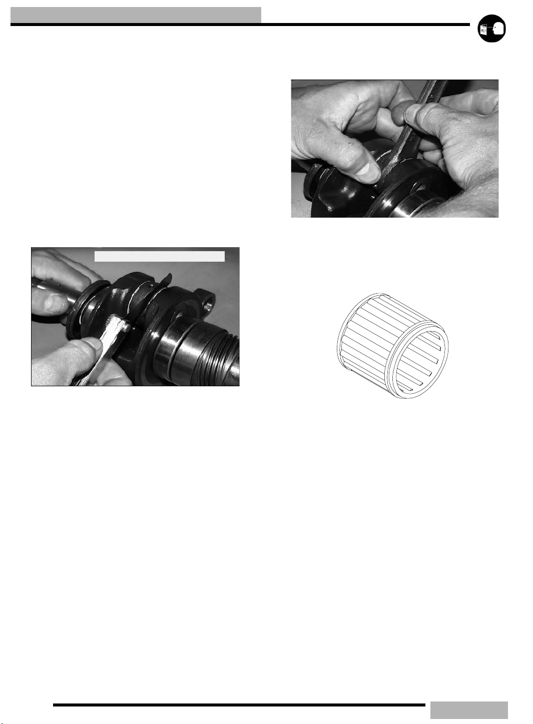
MAINTENANCE
MAIN BEARING
Clean crankshaft thoroughly and oil main and connecting rod
bearings with Polaris engine oil. Carefully check each main
bearing on the shaft.
Due to extremely close tolerances, the bearings must be
inspected visually, and by feel. Look for signs of
discoloration, scoring or galling. Turn the outer race of each
bearing. The bearings should turn smoothly and quietly. The
inner race of each bearing should fit tightly on the crankshaft.
The outer race should be firm with minimal side to side
movement and no detectable up and down movement. Replace
any loose or rough bearings.
CONNECTING ROD (BIG END) BEARING
Within .002” (.05mm)
side clearance is excessive or if there is any up and down
movement detectable in the big end bearing.
WRIST PIN BEARING
1. Clean the end of the connecting rod and inspect inner bore
with a magnifying glass. Look for any surface
irregularities including pitting, wear, or dents.
Specialized equipment and a sound knowledge of crankshaft
repair and straightening is required to perform crankshaft
work safely and correctly. Crankshaft repair should be
performed by trained Polaris service technicians in a properly
equipped shop.
Measure connecting rod big end side clearance with a feeler
gauge. 500/600 Libertyt engines should have a clearance of
.011 - .030" (.28 -.75mm) and 700/800/900 Libertyt
engines should have .011 - .028" (.28 - .70mm) and be equal
on all rods within .002" (.05mm).
Rotate the connecting rod on the crankshaft and feel for any
rough spots. Check radial end play in rod by supporting rod
against one thrust washer and alternately applying up and
down pressure. Replace bearing, pin, and thrust washers if
NEEDLE BEARING
2. Run you fingernail around the inside of the rod and check
for rough spots, galling, or wear.
3. Oil and install needle bearing and pin in connecting rod.
4. Rotate pin slowly and check for rough spots or any
resistance to movement.
5. Slide pin back and forth through bearing while rotating
and check for rough spots.
6. With pin and bearing centered in rod, twist ends back and
forth in all directions to check for excessive axial play.
7. Pull up and down evenly on both ends of pin to check for
radial play.
8. Replace pin and bearing if there is any resistance to
rotation or excessive axial or radial movement. If play or
roughness is evident with a new pin and bearing, replace
the connecting rod.
3.10
Page 73

MAINTENANCE
CRANKSHAFT INDEXING
Dial Indicator
Degree
Wheel
MAG
.100 ATDC
Crankshaft center l ine
Dial Indicator
Degree
Wheel
.100 ATDC
PTO
CAU T ION
Disconnect the battery ground cable and ALL spark
plug high tension leads. Ground high tension leads to
the engine. Disconnect lanyard (if equipped) and/or
press the engine stop switch before proceeding with
the following procedure.
Polaris uses crankshafts that are pressed together. The
connecting rod journal center lines are indexed 180_(twins).
It is sometimes necessary to check multi-cylinder crankshafts
to verify that one cylinder has not been forced out of position
relative to the other cylinder. Some causes for a “out of index”
crankshaft include but ar not limited to the following:
• Hydraulock from water or fuel
• Impact to drive clutch from object or accident
• Abrupt piston or other mechanical failure
• Engine lock-up due to drive belt failure
8. Bend the pointer or move the degree wheel until the
pointer aligns with a 180_ mark on the degree wheel.
9. With the pointer aligned, make sure the degree wheel and
pointer are secured and will not move out of position. Recheck accuracy of this location a few times. The pointer
should align with the 180_ mark when the dial indicator
reads .100” (2.54mm) ATDC.
NOTE: Do not move the crankshaft, degree wheel or
pointer after the initial setting on the MAG end
cylinder - simply read the wheel and dial indicator.
10. Remove the dial indicator and install in PTO cylinder.
Repeat finding TDC. Note the degree wheel indication
when the dial indicator reads .100" ATDC. It should be
180_ (+/-2_) from the MAG cylinder mark.
Symptoms of an out of index crankshaft can include but are
not limited to the following:
• Difficulty calibrating carburetor (repetitive plug fouling
on one cylinder with no other cause)
• Unexplained piston failure on one cylinder (i.e. severe
detonation, broken ring lands, piston holing)
• Excessive vibration of engine, back firing, etc.
• Rough idle, poor top speed.
CRANKSHAFT TRUING
Lubricate the bearings and clamp the crankshaft securely in
the holding fixture.If truing the crankshaft requires striking
with a hammer, always be sure to re-check previously
straightened areas to verify truing. Refer to the illustrations
below. Use Crankshaft alignment kit PN 2870569.
CHECKING CRANKSHAFT INDEX
1. Remove the drive belt, see DRIVE BELT in Chapter 7.
2. Remove the drive clutch, see “DRIVE CLUTCH
REMOVAL” on page 7.10.
3. Securely fasten a large degree wheel on the flywheel or
PTO end of the crankshaft. Make sure that it is mounted
concentrically with the crankshaft center line.
4. With a section of wire (wire coat hanger), anchor it to a
convenient spot. Bend one end at the outer perimeter of the
degree wheel as shown above.
5. Install a dial indicator into the magneto end cylinder spark
plug hole. The ignition timing is referenced by the
magneto end.
6. Locate TDC as accurately as possible by finding the center
of the point where there is no piston movement note the
”Zero” the dial indicator at this point.
7. Continue to rotate the crankshaft in the normal direction of
rotation until the dial indicator reads .100" (2.54mm) after
top dead center (ATDC).
3.11
Page 74

MAINTENANCE
NOTE: The Rod Pin position in relation to the dial
indicator tells you what action is required to
straighten the shaft.
Table 3-3: Truing Examples
To correct a situation like this. Strike the shaft at point
A with a brass hammer.
HIGH .004 (.1mm)
A
B
SUPPORT CRANKSHAFT
AT THESE TWO BEARINGS
HIGH .004 (.1mm)
To correct a situation like the one shown in this.
Squeeze the crankshaft at point A. You will use the
tool from the alignment kit PN 2870569.
If the crank rod pin location is 180_ from the dial
indicator (opposite of above), it will be necessary to
spread the crankshaft at the A position as shown in
illustration 3. When rebuilding and straightening a
crankshaft, straightness is of utmost importance.
Runout must be as close to zero as possible.
HIGH .002 (.05mm)
AA
HIGH .002 (.05mm)
A
A
HIGH .005 (.13mm)
HIGH .005(.13mm)
CRANKSHAFT RUNOUT INSPECTION
Crankshaft runout can be checked with the engine in the
machine. Using a dial indicator with the crankshaft holding
fixture (PN 2870569) will yield the most accurate results.
3.12
Page 75

MAINTENANCE
7
When checking the crankshaft runout on the MAG side. Place
the dial indicator end at 1/2” (12.7mm) from the bearing flat
(A).
MAG END
A
1/2”(12.
When checking the crankshaft runout from the PTO side.
Place the dial indicator end where the taper starts after the
bearing flat (B).
PTO END
PTO END
B
reservoir with the appropriate Polaris injector oil. This will
add pressure to the oil lines.
2. Loosen the bleed screw (A). After approximately 30
seconds oil should flow from beneath the screw head. This
will indicate the pump is free of the air.
3. Tighten bleed screw (A) securely.
NOTE: Any time that the engine is disassembled or
repaired, it is important that the oil supply from the
oil pump be checked and full of oil.
IMPORTANT: The oil pump must always be bled
following any service to the oil injection system or
engine.
FITTING TYPES
BANJO TYPE
B
C
NOTE: Acceptable crankshaft runout (in a crank
fixture) is 0 - .0015” (0 - .04mm) on Liberty
0 - .0025” (0 - .07mm) on Fuji engines.
t engines.
OIL PUMP BLEEDING
A
VERIFYING CHECK VALVE OPERATION
1. To check the operation of the fittings, fill the oil reservoir,
bleed the pump.
2. Remove the check valve (A,B) from the component.
3. Place the oil line (with check valve) in a safe area where no
moving engine part will make contact with it.
4. Start the engine and let it idle for approximately 1-2
minuets.
5. Drops of oil should be visible from the check valve after
the engine has idled 1 to 2 minuets, with a drop occurring
every few seconds.
6. If oil does not flow from one of the check valves, remove
the oil line from the check valve and repeat step 4, if oil is
present during this test replace the faulty check valve.
NOTE: Valves should open with 2-7 lbs of pressure.
NOTE: Install new sealing washers (C) upon
installation on either side of the banjo check valve.
If oil does not flow with the check valves removed from their
feed lines, check the following
• In line filter blocked
• Air may not be bled from the oil pump
1. To aid in bleeding the air out of the oil lines, fill oil
• Feed lines leaking
3.13
Page 76

MAINTENANCE
• Oil tank vent restricted or kinked
• Defective pump
OIL / FUEL FILTER
CAU T ION
The in tank fuel filter and fuel lines should be inspected
regularly. Special attention should be given to the fuel
line condition after periods of Summer storage. Normal
deterioration from weather and fuel can occur during
this storage period. Do not damage fuel lines when removing them. If a fuel line has been damaged or kinked
it must be replaced.
NOTE: The direction of the arrow indicates the
direction of the flow through the filter. After
changing the oil filter, the oil injection system must
be bled of all trapped air. see “OIL PUMP
BLEEDING” on page 3.13.
Most models use an oil and fuel filters which are of a special
design and must not be substituted. These filters should be
changed and the oil and fuel lines should be inspected
annually or every 1000 miles (1600 km).
These filters may have an arrow on the filter or line. This
arrow is the direction of flow. Install accordingly.
BRAKE LEVER TRAVEL
The brake lever travel should have a clearance no less than 1/
2” (1.27cm) from the handlebar grip. Inspection should be
made with the lever firmly depressed. If the lever has less than
this amount you may need to bleed the brake system, see
“BRAKE FLUID REPLACEMENT & BLEEDING” on
page 8.3.
BRAKE FLUID
WARNI N G
Do not over fill the master cylinder. Fluid expansion
could cause brakes to lock, resulting in serious injury or
death. Once a bottle of brake fluid is opened, use what
is necessary and discard the rest. Do not store or use
a partial bottle of brake fluid. Brake fluid is hygroscopic,
meaning it rapidly absorbs moisture from the air. This
causes the boiling temperature of the brake fluid to
drop, leading to early brake fade and the possibility of
serious injury
EDGE models utilize a special oil filter that is built into the
oil sending unit located in the bottom of the oil tank. It should
be replaced every two years or 2400 miles (3862 km).
700/900 FUSION/RMK models use the in-line filter and
should be replaced every two years or 2400 miles (3862 km).
3.14
Inspect the reservoir to be sure it contains the correct amount
of fluid. Use only Polaris DOT 4 high temperature brake fluid.
Change fluid every 2 years or whenever the fluid is dark or
contamination is suspected.
Page 77

NOTE: A low brake fluid level can be indicated
through the sight glass on the cover. If the fluid is
low this sight glass will glow a brighter. color.
MAINTENANCE
LOW
FULL
BRAKE FLUID BLEEDING
see “BRAKE FLUID REPLACEMENT & BLEEDING” on
page 8.3.
3.15
Page 78

MAINTENANCE
EXHAUST SYSTEM
M
L
G
B
C
K
A
F
D
I
H
J
E
AA
At approximately 2000 miles, or in preparation for off season
storage, it is a good idea to check the exhaust system for wear
or damage. To inspect, allow the engine and exhaust system to
cool completely. Open the hood and inspect the muffler and
pipes for cracks or damage. Check for weak or missing
retaining springs, and also check the damper/support
grommets.
Springs are installed in such a way so that the opening of the
hook that you are puling on is facing the item being held.
Stainless steel (gray color) springs (AA) are located at the
header pipe. Other (gold color) springs (A) are everywhere
else.
EXHAUST REMOVAL
1. Let engine and exhaust system to cool completely before
preforming any service.
2. Disconnect and remove all the exhaust springs (A and
AA).
NOTE: The stainless steel springs (gray in color),
hold the exhaust pipe to the manifold are designed
to handle higher temperature ranges then the other
springs.
3. Disconnect the exhaust temperature sensor (if equipped).
4. Remove the exhaust pipe (C), resonator seal (D) and
manifold seal (E).
5. Remove the resonator (F). Some models use rubber
isolators (G) and will need the nut (L) removed in order to
remove the resonator.
6. Remove the manifold (H) and gaskets (I) by removing the
manifold mounting bolts (J).
7. Check the condition of the vibration dampener (K) and
replace if damaged.
8. Check the condition of the resonator outlet boot (M) and
replace if damaged.
EXHAUST INSTALLATION
1. Install new exhaust manifold gaskets (I).
2. Place the exhaust manifold (H) on to the engine and torque
the mounting bolts (J) to 18 ft-lb(24Nm).
3. Install the resonator (F). Some models utilize resonator
locating tabs (M) that need to be lined up and pushed down
to assure the correct position.
4. If rubber isolators (G) are used on the resonator, secure
them by installing the isolator nuts (L).
5. Check the condition of the vibration dampener (K) and
replace if it is damaged.
6. Insert the exhaust seals (D,E) onto the manifold (H) and
3.16
Page 79

MAINTENANCE
the exhaust pipe (C).
7. Install the exhaust pipe on the manifold and resonator.
8. Install all the exhaust springs.
Too high on initial engagement
A
Belt deflection is critical for optimum belt performance and
belt life. It should be checked at 500 miles (800km) and then
in 1000 mile (1600km) increments after that.
Too much belt deflection is when the belt is too long or the
center distance is too short. The initial starting ratio will be too
high, resulting in performance loss. This is due to the belt
rising too high in the drive clutch sheaves upon engagement
(A).
Not enough belt deflection (B) is when the belt is too short or
the center distance is too long. The initial starting ratio will be
too low. In addition, the machine may creep when the engine
idles, causing damage to the internal face of the drive belt.
MEASURING BELT DEFLECTION
1. Measure the belt deflection with both clutches at rest and
in their full neutral position.
2. Place a straight edge across the tow clutches, on top the
belt.
3. Apply downward pressure to the belt and measure the
distance at point (D).
4. The measurement should be 1 1/4” (3.2cm).
5. If the measurement is not correct adjust driven clutch, See
“TEAM BELT DEFLECTION” on page 26.
BELT DEFLECTION
1 1/4”
Belt too tight
B
Straight Edge
LUBRICATION
GREASE POINTS
NOTE: A grease gun kit (PN 2871312) comes with
grease and adapters to lubricate all the fittings
needed to service Polaris snowmobiles.
Lubricate the following fittings with Polaris Premium All
Season grease every 1000 miles (1600 km) and before summer
storage. When applying grease to these points, free up all the
weight form the component being greased to permit better
penetration.
• Ski spindles
• Ski pivots
• Steering post pivots
• Rear suspension pivot shafts
• Jackshaft
• Driveshaft
JACKSHAFT BEARING
1. Loosen the driven clutch retaining bolt and pull the clutch
away form the flange fitting to expose the bearing grease
point.
2. Apply grease with the grease gun with just a few pumps.
3. Install the driven clutch see “DRIVEN CLUTCH
INSTALLATION” on page 7.20.
3.17
Page 80

MAINTENANCE
DRIVESHAFT BEARING
1. Locate the driveshaft bearing grease zerk that is located on
the flange of the bearing cover.
2. Apply a few pumps of grease into the grease zerk and
clean up any residual grease on the fitting.
REAR SUSPENSION
To maintain rider comfort and to retard wear of the pivot
shafts, the suspension pivot shafts should be lubricated with
Polaris Premium All Season Grease at 500 miles (800 km)
initially; 1000 miles (1600 km) and before summer storage
each year. The riding characteristics of the snowmobile will be
affected by lack of lubrication of these shafts.
CHAINCASE
The drive chain is continuously immersed in the chaincase oil.
Depending on the style chaincase the proper oil level is
determined by checking on the dipstick or sight glass. To get
an accurate level reading the machine must be placed on a
level surface.
CAU T ION
The dip stick also has safety magnetic tip that catches any
metal shavings that are in the system. This magnetic tip
should be cleaned every time you check the fluid level.It is
common to see shavings during break in of a new gear(s) or
chain.
SIGHT GLASS
SIGHT GLASS
If your chaincase uses a sight glass, make sure that the level of
fluid is even with the mark on the glass. To add fluid to this
style chaincase, add fluid through the fill cover.
The drain plug is magnetic so that any shavings are collected
here. You should remove any shavings from this drain plug
when changing the fluid.
STEERING U JOINT
The steering U joint should be
lubricated with Polaris fogging oil
(PN 2870791). Follow the
maintenance chart at the
beginning of this chapter.
Do not mix or use improper types of lubricants in the
chaincase. Excessive wear to chain, sprockets and
bearings may result.
DIP STICK
MAGNETIC END
DIP STICK
If your chaincase has a dip stick, the correct level will be
indicated between the “SAFE” markings. To add fluid to this
style chaincase you can add it through the dipstick hole.
SAFE FLUID AREA
3.18
Apply
Fogging
Oil
Page 81
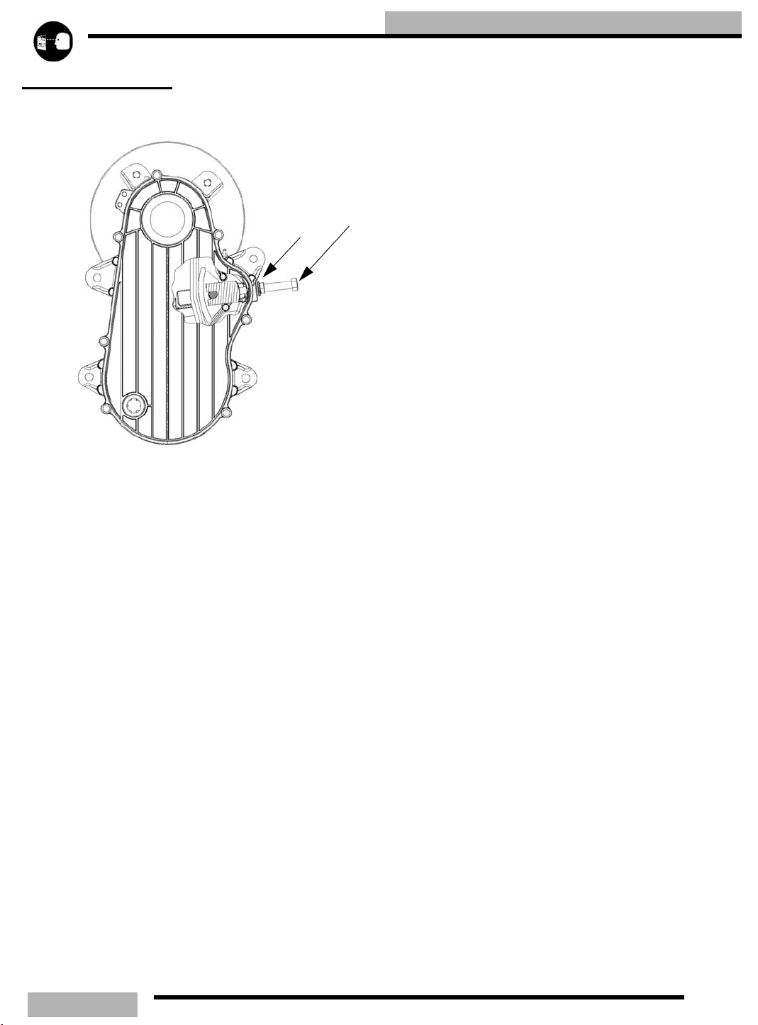
ADJUSTMENT
CHAINCASE DRIVE TENSION
MAINTENANCE
A
B
1. Elevate the rear of the machine so that the track is off the
floor.
2. Rotate the driven clutch counterclockwise to move all the
chain slack to the tensioner side.
3. Lock the parking brake.
4. Loosen the adjuster bolt jam nut (B)
5. Finger tighten the adjuster bolt (A).
6. Back off the adjuster bolt 1/4 turn out (counterclockwise).
7. Tighten the jam nut while holding the adjuster bolt.
8. Release parking brake.
NOTE: It may be necessary to remove the exhaust
pipe and resonator to access this area.
3.19
Page 82

MAINTENANCE
TRACK ALIGNMENT
A
NOTE: Track alignment affects track tension.
Misalignment of the track will cause excessive wear
to the track, rail slides, and rail.
NOTE: Excessive rail slide wear occurs due to
running in inadequate snow conditions.
Periodically check that the track is centered and running
evenly on the slide rails. Misalignment will cause excessive
wear to the track and slide rails.
1. Safely lift and support the rear of the snowmobile off the
ground.
2. Rotate the track by hand to check for any possible damage.
3. Inspect the track rods (A) carefully and examine the track
along the entire length of each rod, bending the track edge
and inspecting it for breakage. If any rod damage is found,
the track should be replaced.
4. Warm up the track by starting the engine and apply a small
amount of throttle so the track runs slowly at least five
complete revolutions.
5. Stop the engine and turn the ignition off.
6. Inspect track alignment by carefully looking through the
track window (B) to make sure the rails (C) are evenly
spaced on each side.
7. Before any adjustments are made loosen up the rear idler
shaft (F).
8. If the track runs to the left, loosen the left locknut and
tighten the left adjusting bolt (D). If the track runs to the
right, loosen the right locknut and tighten the right
adjusting bolt. It may be necessary to check this with the
engine rotating the track. Be sure to SHUT THE
MACNINE OFF before making any further adjustments.
9. After any adjustments are complete, be sure to torque the
locknuts (E) to 35 ft-lb (48Nm).
B
D
C
10. Torque both idler shaft bolts (F) to 35 ft-lb (48Nm).
F
E
WARNI N G
Broken track rods can cause a rotating track to come off
the machine. Never operate or rotate a damaged track
under power with a broken rod. Serious injury or death
may occur.
WARNI N G
When performing the following checks and adjustments, stay clear of all moving parts to avoid personal
injury. Never make any adjustments with the engine
running, as serious personal injury can result.
TRACK LUBRICATION
WARNI N G
Operating with insufficient lubrication between the rail
slide and track guide clips can cause track failure, loss
of vehicle control and loss of braking ability, which can
result in serious injury or death. Avoid operating vehicle
on ice and other surfaces that have little or no snow
conditions.
The slide rail needs snow for lubrication and cooling.
Excessive wear indicates insufficient lubrication. A new rail
slide can cause faster heat build-up in limited lubrication,
resulting in excessive wear.
NOTE: If excessive rail slide wear occurs due to
poor snow conditions additional wheel kits can be
added.
3.20
Page 83

MAINTENANCE
NOTE: Track damage of failure caused by operation
on ice or under other poor lubrication conditions will
void the tracks warranty.
TRACK TENSION
F
B
C
A
D
TRACK
Track tension is critical for maintaining correct suspension
operation. If the track tension is too loose it may cause the
track to slip or “ratchet” on the drive shaft drivers and cause
the track and rear suspension durability problems. If the track
is too tight the track will wear down the rail slides, reduce top
o
16”(41cm)
E
speeds, cause rear suspension vibration and cause track and
rear suspension durability problems.
1. Lift the rear of the machine and place a jack stand or secure
the rear of the machine so that the track is off of the
ground.
2. Start the engine and slowly let the engine turn the track
over. This will warm up the track for a correct
measurement.
3. Shut off the engine.
4. Place a 10 lbs. (4.54kg) weight at point (A). Point (A) is
16” (41cm) ahead of the rear idler shaft (E).
5. Measure the distance (D) between the rail slider and the
track. This measurement should fall with in the
measurement range for the appropriate vehicle.
6. If adjustment is needed, loosen up the lock nuts (B) on
each side.
7. Loosen up the idler shaft bolts (F).
8. Turn each adjuster bolt (C) toward the idler wheel
(clockwise) if you need less of a measurement. Tun the
adjuster bolt (C) toward the front of the sled
(counterclockwise) if you need a greater measurement.
9. When you achieve the correct tension listed below, torque
the lock nuts (B) and idler shaft bolts on each side to 35 ftlb (48Nm).
NOTE: Track alignment affects track tension.
Misalignment will cause excessive wear to the track
and slide rails. Excessive slide wear will appear on
units with the track tension set too tight (or below
measurement specification).
Table 3-4: Track Tension Data
SUSPENSION MEASUREMENT
EDGE / EDGE RMK / SWITCHBACK/ IQ RMK / IQ
SWITCHBACK
IQ FUSION 7/8” - 1 1/8” (2.2 - 2.9cm)
M-10 7/8” - 1 1/8” (2.2 - 2.9cm)
M-10 128” 7/8” - 1 1/8” (2.2 - 2.9cm)
M-10 136” 7/8” - 1 1/8” (2.2 - 2.9cm)
EDGE TOURING / WIDETRAK 3/4”- 1” (1.9 - 2.5cm)
EDGE 136” 7/8” - 1 1/8” (2.2 - 2.9cm)
120 PRO X 3/8” (.95cm)
3/8” - 1/2” (1 - 1.3cm)
3.21
Page 84
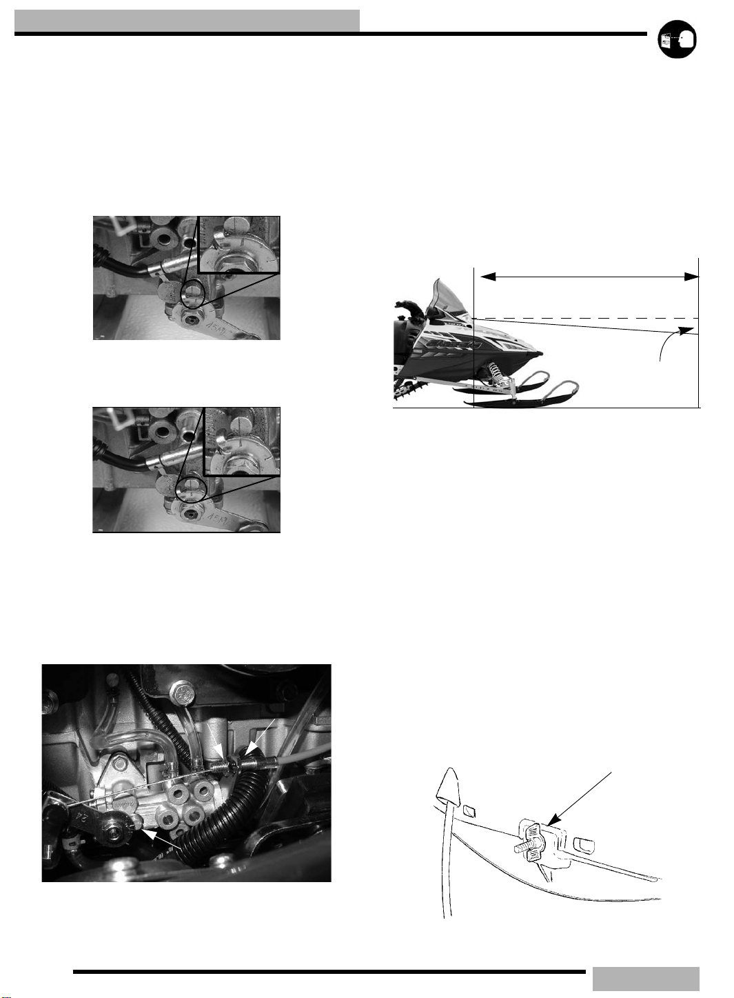
MAINTENANCE
OIL PUMP ADJUSTMENT
1. On some engines the oil pump is located under the intake
boots and you may have to remove the air box and may
need to unplug the CDI box and coils.
2. Verify carburetor synchronization see “THROTTLE
VALVE SYNCRONIZATION” on page 4.13.
3. Loosen the carburetor boot adapters and carefully move
them so that you can see and adjust the oil pump cable.
3
4. Verify that the oil pump alignment lines are aligned at the
point where the carburetor slides begin to raise from their
resting positions.
4
5. If they are not aligned make the necessary adjustments by
adjusting the oil pump cable. In small increments, loosen
the lock nut that is closest to the oil pump (A). and move
the mark that is on the oil pump arm by tightening or
loosening the adjustment nut (B) as needed to get the line
to the desired position (550 has alignment marginal at
wide open throttle).
600 Liberty
A
B
4.
8. Re-install carburetors, air box and plug in the CDI and
coils if they were taken off in step 1.
9. Check idle to specification and adjust if needed.
NOTE: A mirror may aid in checking the oil line
markings.
HEADLIGHT ADJUSTMENT
The headlight can be adjusted for vertical aim using the
following procedure:
25ft.(7.6m)
LAMP CENTER LINE
o
2”(5.1cm)
1. Place the snowmobile on a flat level surface with the
headlight approximately 25 feet (7.6m) from a wall.
2. With a tape measure, measure the center line of the
headlight on the vehicle. You may have to eye up the
center line.
3. Mark the headlight center line distance that you found on
step 4, and mark it on the wall that the machine is facing.
4. Apply and lock the parking brake.
5. Start the engine.
6. Set the headlight switch to HIGH beam.
7. With the rider in full gear and the sled at ride height
continue to step 8.
8. Observe the headlight aim. The most intense part if the
headlight beam should be aimed 2”(5.1cm) below the
mark placed on the wall in step 3.
NOTE: On Edge models you can adjust the
headlight by turning the adjusting knob that is
located on the under side of the hood, just below the
head lamp opening.
EDGE headlight adjustment knob
WALL
C
6. Lock the lock nut (A).
7. Verify that the oil pump marks line up as outlined in step
3.22
Page 85

MAINTENANCE
NOTE: On IQ models you can adjust the headlight
by turning the adjustment knob that is located on the
top side of the hood, next to the MFD gauge.
IQ adjustment knob
HANDLEBAR ADJUSTMENT
C
B
A
D
12 (16)
E
6. While holding the handlebar in the desired position tighten
the handle bar block bolts and torque to 12 ft-lb (16Nm)
starting with the front bolts.
7. Replace the console covers (if equipped), handle bar cover,
handle bar cover slides, and dart clips.
HANDLEBAR RIDING POSITION
ADJUSTMENT (Rider Select only)
A
B
IQ RIDING ADJUSTMENT
WARNI N G
Do not attempt to adjust the riding position while vehicle is in motion. Loss of steering may result in personal
injury or death.
F
HANDLEBAR ROTATING ADJUSTMENT
G
WARNI N G
Improper adjustment of the handlebars, or incorrect
torquing of the of the adjuster block can cause limited
steering or loosening of the handlebars resulting in a
loss of control situation.
1. Remove the handle bar cover slides (A) and then the dart
clips (B) that holds on the handle bar cover (C).
2. Remove the handle bar cover.
3. Remove the console covers (D) if equipped.
4. Loosen the handle bar block bolts (E) and nuts (F).
5. Rotate the handle bar (G) in the desired position.
On the IQ vehicles you have the option of seven (7) different
riding positions.
1. While sitting in the riding position on the vehicle, press
down on the adjustable steering lever (A).
2. Adjust the handle bar (B) position to the desired position
and let go of the steering lever.
3. Push handle bars forward and then pull backward on them
to verify that the position is locked.
3.23
Page 86

MAINTENANCE
THROTTLE LEVER FREE PLAY
D
E
F
C
A
gap=.010-.030”
.25-.80mm
Throttle lever free play must always be at a specified
clearance (A) .010”-.030” (.25-.80 mm) between the throttle
lever (B) and the throttle block (C). This clearance is
controlled by the throttle cable (D).
If adjustment is needed follow these steps:
B
THROTTLE FREE PLAY
TORQUE STOP
B
After aligning clutches, adjust torque stop (A) by loosening
the lock nut and rotating the stop so that the clearance is .010”
- .030” (.25 - .75mm) from the whole surface of the torque
stop.
If replacing a new torque stop, adjust the torque stop so that
the tip (B) is touching the engine case.
Hold torque stop and tighten jam nut to 15-17 ft-lb. (21-24
Nm).
A
TORQUE STOP
CAU T ION
After any idle speed adjustments are made, the throttle
lever clearance and the oil pump adjustment must be
checked and adjusted.
1. Check the idle RPM and verify it is within the specified
range.
2. Shut off engine.
3. Locate the throttle cable that is attached to the carburetors
and adjust the throttle free play by adjusting the barrel nut
(E) and lock nuts (F).
4. Once you achieve the proper free play of .010”-.030” (.25.80mm), tighten the lock nuts.
5. Verify the oil pump index marks are with in range.
6. Check the idle RPM and verify it is within the specified
range.
NOTE: If the idle speed screw is adjusted inward
and the cable sleeve is not adjusted to take up the
throttle lever clearance, the engine may misfire or
kill upon initial throttle opening.
CLEANING
AIR FILTER
A
A
AIR FILTER CLEANING
The intake foam filter (A) limits snow ingestion into the
intake system. When operating in loose powder, check the top
of the foam filter periodically to remove any accumulation of
snow.
NOTE: Do not operate a machine with the intake
filters removed. This may cause carburetor icing
resulting poor fuel economy or engine damage.
A
3.24
Page 87

MAINTENANCE
WATER SEDIMENT TRAP
WARNI N G
When draining the traps, fuel spillage will occur. be
sure to work in a well ventilated area away from anything which may cause the fuel to ignite such as an
open flame, heaters, trouble lights or cigarettes.
Most Polaris
snowmobiles
incorporate a
patented
carburetor bowl
water / sediment
traps which are
located at the
bottom of each
carburetor. The
trap consists of a
hose with a plug
which should be
inspected for
contamination
every 1000 miles
(1600 km).
1. Turn the fuel tank supply valve to the “OFF” position.
2. Position a container or shop towels under the work area to
help catch some of the contaminated gasoline.
3. Slide the clamp (A) away from the drain plug (B) and
remove it from the sediment tube and drain the
contaminated material from the bowl. Repeat for each
carburetor.
4. Wipe off the residue from the plug and reinstall the
clamps.
A
B
NOSEPAN CARE
If the machine is equipped with a battery, disconnect the
battery cables and clean the cables and battery posts. Fill
battery to proper level with distilled water and charge to full
capacity. Remove and store the battery in a cool dry place.
The machine should be stored in a dry garage or shed out of
the sunlight and covered with a fabric snowmobile cover. Do
not use plastic to cover the machine; moisture will be trapped
inside causing rust and corrosion problems.
CLUTCH AND DRIVE SYSTEM
Remove drive belt and store in a cool dry location. Lubricate
sheave faces and ramps of drive and driven clutches with light
oil or rust inhibitor. All lubrication applied as a rust
preventative measure must be cleaned off before installing belt
for service and operating machine.
CONTROLS AND LINKAGE
All bushings, spindle shafts and tie rod ends should be coated
with a light coat of oil or grease. Throttle controls and cables
should be lubricated. Force a small amount of lubricant down
cables.
ELECTRICAL CONNECTIONS
Separate electrical connector blocks and clean corrosive buildup from connectors. Lubricate or pack connector blocks with
Nyogelt grease and reconnect. Replace worn or frayed
electrical wire and connectors.
CARBURETOR/THROTTLE BODY
Fog engine with Polaris Fogging Oil (aerosol type) according
to directions on can.
FUEL SYSTEM
Treat the fuel system with Polaris Carbon Clean. If Polaris
Carbon Clean is not used, fuel tank, fuel lines, and carburetor
should be completely drained of gasoline.
If your nosepan becomes dirty with soot, you can use Polaris
Carbon Clean (PN 2872890) to remove the soot.
STORAGE
CHASSIS AND HOOD
Proper storage starts by cleaning, washing and waxing the
hood, chassis, upholstery and plastic parts. Clean and touch up
with paint any rusted or bare metal surfaces. Ensure that all
corrosive salt and acids are removed from surfaces before
beginning preservation with waxes and rust inhibitors (grease,
oil, or paint).
CORROSION
To prevent corrosion, always grease jackshaft and drive shaft
(clutch side) bearings with Polaris Premium all season grease.
Loosen driven clutch retaining bolt and pull clutch outward to
expose bearing. Use a point type grease gun fitting to inject
grease through hole in flangette into bearing until grease
purges out inside or outside bearing seal. Push clutch back on
shaft and replace clutch retaining bolt. Inject grease into fitting
on speedometer drive adaptor until grease purges out inside or
outside the bearing seal. Lubricate both front ski pivots at
bushings and spindles.
3.25
Page 88

MAINTENANCE
SHOCKS
Use T-9 Metal Protectant (or equivalent) on shock absorber
shafts to help prevent corrosion.
BATTERY
Disconnect and remove the battery. Clean the terminals and
cables. Apply dielectric grease to the terminals. Store in a cool
dry place for storage.
REPLACEMENT
HEADLIGHT BULB REPLACEMENT
NOTE: Do not touch the bulb with your fingers. The
grease from body oil will cause a hot spot on the
bulb and cause bulb failure. If you do touch the bulb
clean the bulb with isopropyl alcohol.
EDGE HEADLIGHT BULB REPLACEMENT
IQ HEADLIGHT BULB REPLACEMENT
1
2
3
4
1. Unplug the headlight harness (1) form the bulb.
2. Remove the rubber boot (2) from the housing.
3. Pinch the ends of the spring (3) together and lift it until it
releases from the spring retainer.
4. Lift spring carefully around the wire harness and flip it to
the outside of the housing.
5. Grasp the bulb (4) by the metal base and carefully separate
the bulb from the harness.
6. Instal new bulb by the base and reverse the process for
installation.
SLIDE
PUSH
1. Push in on the “PUSH” section of the plenum.
2. Slide the access panel down to gain access to the bulb.
3. Squeeze and move the bulb clip up.
4. Replace the bulb, clip and access panel.
5
6
7
IQ SNOW BEAM BULB REPLACEMENT
1. Twist the light base (5) counterclockwise and pull it out
from the housing.
2. Remove the rubber boot (6).
3. Remove the bulb (7) by pulling it straight out from the
housing.
4. Replace bulb with new and reverse the process for
installation.
3.26
Page 89

CARBURETION
CHAPTER 4
CARBURETION
WARNINGS . . . . . . . . . . . . . . . . . . . . . . . . . . . . . . . . . . . . . . . . . . . . . . . . . . . . . . . . . . 4.2
WARNINGS . . . . . . . . . . . . . . . . . . . . . . . . . . . . . . . . . . . . . . . . . . . . . . . . . . . . . . . . . . . 4.2
GENERAL INFORMATION . . . . . . . . . . . . . . . . . . . . . . . . . . . . . . . . . . . . . . . . . . . . . . 4.2
SERVICE PRECAUTIONS. . . . . . . . . . . . . . . . . . . . . . . . . . . . . . . . . . . . . . . . . . . . . . . . 4.2
GASOLINE VOTALITIY . . . . . . . . . . . . . . . . . . . . . . . . . . . . . . . . . . . . . . . . . . . . . . . . . . 4.3
2 STROKE GASOLINE / OIL PRE MIX . . . . . . . . . . . . . . . . . . . . . . . . . . . . . . . . . . . . . . 4.3
FUEL DELIVERY SYSTEM (CARBURETED) . . . . . . . . . . . . . . . . . . . . . . . . . . . . . . . . 4.3
CARBURETED SYSTEM OVERVIEW . . . . . . . . . . . . . . . . . . . . . . . . . . . . . . . . . . . . . . 4.3
FUEL PUMP (NON-INJECTED UNITS) . . . . . . . . . . . . . . . . . . . . . . . . . . . . . . . . . . . . 4.4
FUEL PUMP OVERVIEW . . . . . . . . . . . . . . . . . . . . . . . . . . . . . . . . . . . . . . . . . . . . . . . . 4.4
MAINTENANCE . . . . . . . . . . . . . . . . . . . . . . . . . . . . . . . . . . . . . . . . . . . . . . . . . . . . . . . . 4.5
OPERATION . . . . . . . . . . . . . . . . . . . . . . . . . . . . . . . . . . . . . . . . . . . . . . . . . . . . . . . . . . 4.5
CLEANING. . . . . . . . . . . . . . . . . . . . . . . . . . . . . . . . . . . . . . . . . . . . . . . . . . . . . . . . . . . . 4.5
INSPECTION . . . . . . . . . . . . . . . . . . . . . . . . . . . . . . . . . . . . . . . . . . . . . . . . . . . . . . . . . . 4.5
MIKUNI JET NEEDLE . . . . . . . . . . . . . . . . . . . . . . . . . . . . . . . . . . . . . . . . . . . . . . . . . . 4.5
OVERVIEW . . . . . . . . . . . . . . . . . . . . . . . . . . . . . . . . . . . . . . . . . . . . . . . . . . . . . . . . . . . 4.5
MIKUNI TM 38 . . . . . . . . . . . . . . . . . . . . . . . . . . . . . . . . . . . . . . . . . . . . . . . . . . . . . . . . 4.6
CARBURETOR OVERVIEW . . . . . . . . . . . . . . . . . . . . . . . . . . . . . . . . . . . . . . . . . . . . . . 4.6
MIKUNI CARBURETOR . . . . . . . . . . . . . . . . . . . . . . . . . . . . . . . . . . . . . . . . . . . . . . . . 4.7
FUNCTION. . . . . . . . . . . . . . . . . . . . . . . . . . . . . . . . . . . . . . . . . . . . . . . . . . . . . . . . . . . . 4.7
FLOAT SYSTEM . . . . . . . . . . . . . . . . . . . . . . . . . . . . . . . . . . . . . . . . . . . . . . . . . . . . . . . 4.7
FUEL METERING . . . . . . . . . . . . . . . . . . . . . . . . . . . . . . . . . . . . . . . . . . . . . . . . . . . . . . 4.8
FUEL DELIVERY . . . . . . . . . . . . . . . . . . . . . . . . . . . . . . . . . . . . . . . . . . . . . . . . . . . . . . . 4.8
PILOT JET . . . . . . . . . . . . . . . . . . . . . . . . . . . . . . . . . . . . . . . . . . . . . . . . . . . . . . . . . . . . 4.8
PILOT AIR SCREW . . . . . . . . . . . . . . . . . . . . . . . . . . . . . . . . . . . . . . . . . . . . . . . . . . . . . 4.8
MAIN JET. . . . . . . . . . . . . . . . . . . . . . . . . . . . . . . . . . . . . . . . . . . . . . . . . . . . . . . . . . . . . 4.8
JETTING GUIDELINES . . . . . . . . . . . . . . . . . . . . . . . . . . . . . . . . . . . . . . . . . . . . . . . . . . 4.9
PISTON VALVE OR THROTTLE VALVE . . . . . . . . . . . . . . . . . . . . . . . . . . . . . . . . . . . . 4.9
JET NEEDLE / NEEDLE JET. . . . . . . . . . . . . . . . . . . . . . . . . . . . . . . . . . . . . . . . . . . . . . 4.9
JET NEEDLE . . . . . . . . . . . . . . . . . . . . . . . . . . . . . . . . . . . . . . . . . . . . . . . . . . . . . . . . . . 4.9
NEEDLE JET . . . . . . . . . . . . . . . . . . . . . . . . . . . . . . . . . . . . . . . . . . . . . . . . . . . . . . . . . 4.10
THROTTLE OPENING VS FUEL FLOW . . . . . . . . . . . . . . . . . . . . . . . . . . . . . . . . . . . . 4.10
MIKUNI TM38 FLAT SLIDE SERVICE . . . . . . . . . . . . . . . . . . . . . . . . . . . . . . . . . . . . 4.11
DISASSEMBLY . . . . . . . . . . . . . . . . . . . . . . . . . . . . . . . . . . . . . . . . . . . . . . . . . . . . . . . 4.11
ASSEMBLY . . . . . . . . . . . . . . . . . . . . . . . . . . . . . . . . . . . . . . . . . . . . . . . . . . . . . . . . . . 4.12
CARBURETOR SYNCRONIZATION. . . . . . . . . . . . . . . . . . . . . . . . . . . . . . . . . . . . . . 4.13
THROTTLE VALVE SYNCRONIZATION. . . . . . . . . . . . . . . . . . . . . . . . . . . . . . . . . . . . 4.13
THROTTLE POSITION SENSOR . . . . . . . . . . . . . . . . . . . . . . . . . . . . . . . . . . . . . . . . 4.14
SETTING THE TPS . . . . . . . . . . . . . . . . . . . . . . . . . . . . . . . . . . . . . . . . . . . . . . . . . . . . 4.14
CARBURETOR CABLE ADJUSTMENTS . . . . . . . . . . . . . . . . . . . . . . . . . . . . . . . . . . 4.15
CHOKE ADJUSTMENT . . . . . . . . . . . . . . . . . . . . . . . . . . . . . . . . . . . . . . . . . . . . . . . . . 4.15
THROTTLE LEVER FREEPLAY . . . . . . . . . . . . . . . . . . . . . . . . . . . . . . . . . . . . . . . . . . 4.15
CARBURETOR COMPONENT PART NUMBERS . . . . . . . . . . . . . . . . . . . . . . . . . . . 4.16
MIKUNI PILOT JETS . . . . . . . . . . . . . . . . . . . . . . . . . . . . . . . . . . . . . . . . . . . . . . . . . . . 4.16
MIKUNI MAIN JETS. . . . . . . . . . . . . . . . . . . . . . . . . . . . . . . . . . . . . . . . . . . . . . . . . . . . 4.16
MIKUNI JET NEEDLES . . . . . . . . . . . . . . . . . . . . . . . . . . . . . . . . . . . . . . . . . . . . . . . . . 4.16
MIKUNI STARTER JETS . . . . . . . . . . . . . . . . . . . . . . . . . . . . . . . . . . . . . . . . . . . . . . . . 4.16
MIKUNI PILOT AIR JETS . . . . . . . . . . . . . . . . . . . . . . . . . . . . . . . . . . . . . . . . . . . . . . . 4.17
MIKUNI PILOT AIR JETS . . . . . . . . . . . . . . . . . . . . . . . . . . . . . . . . . . . . . . . . . . . . . . . 4.17
MIKUNI PISTON VALVES . . . . . . . . . . . . . . . . . . . . . . . . . . . . . . . . . . . . . . . . . . . . . . . 4.17
4
4.1
Page 90

CARBURETION
WARNINGS
WARNINGS
When ever servicing the carburetor or fuel
system, it is important to heed the following
warnings.
WARNI N G
Always stop the engine and refuel outdoors or in a well
ventilated area
WARNI N G
Do not smoke or allow open flames or sparks in or near
the area where refueling is performed or where gaso-
line is stored or used.
WARNI N G
Do not overfill the tank. Do not fill the tank neck.
manual, thoroughly familiarizing him/herself with procedures
before beginning. Photographs and illustrations have been
included with the text as an aid. Notes, cautions and warnings
have also been included for clarification of text and safety
concerns. However, a knowledge of mechanical theory, tool
use and shop procedures is necessary to perform the service
work safely and satisfactorily. Use only genuine Polaris
service parts.
Cleanliness of parts and tools as well as the work area is of
primary importance. Dirt and foreign matter will act as an
abrasive and cause damage to precision parts. Clean the
snowmobile before beginning service. Clean new parts before
installing.
Watch for sharp edges which can cause personal injury,
particularly in the area of the tunnel. Protect hands with
gloves when working with sharp components.
If difficulty is encountered in removing or installing a
component, look to see if a cause for the difficulty can be
found. If it is necessary to tap the part into place, use a soft
face hammer and tap lightly.
Some of the fasteners in the snowmobile were installed with
locking agents. Use of impact drivers or wrenches will help
avoid damage to fasteners.
WARNI N G
If you get gasoline in your eyes or if you swallow gaso-
line, see your doctor immediately.
WARNI N G
If you spill gasoline on your skin or clothing, immediately wash it off with soap and water and change clothing.
WARNI N G
Never start the engine or let it run in an enclosed area.
Gasoline powered engine exhaust fumes are poison-
ous and can cause loss of consciousness and death in
a short time.
GENERAL INFORMATION
SERVICE PRECAUTIONS
In order to perform service work efficiently and to prevent
costly errors, the technician should read the text in this
Always follow torque specifications as outlined throughout
this manual. Incorrect torquing may lead to serious machine
damage or, as in the case of steering components, can result in
injury or death for the rider(s).
If a torquing sequence is indicated for nuts, bolts or screws,
start all fasteners in their holes and hand tighten. Then,
following the method and sequence indicated in this manual,
tighten evenly to the specified torque value. When removing
nuts, bolts or screws from a part with several fasteners, loosen
them all about 1/4 turn before removing them.
If the condition of any gasket or O-Ring is in question, replace
it with a new one. Be sure the mating surfaces around the
gasket are clean and smooth in order to avoid leaks.
Some procedures will require removal of retaining rings or
clips. Because removal weakens and deforms these parts, they
should always be replaced with new parts. When installing
new retaining rings and clips use care not to expand or
compress them beyond what is required for installation.
Because removal damages seals, replace any oil or grease
seals removed with new parts.
4.2
Page 91

CARBURETION
Polaris recommends the use of Polaris lubricants and greases,
which have been specially formulated for the top performance
and best protection of our machines. In some applications,
such as the engine, warranty coverage may become void if
other brands are substituted.
Grease should be cleaned from parts and fresh grease applied
before reassembly of components. Deteriorating grease loses
lubricity and may contain abrasive foreign matter.
Whenever removing or reinstalling batteries, care should be
taken to avoid the possibility of explosion resulting in serious
burns. Always disconnect the negative (black) cable first and
reconnect it last. Battery electrolyte contains sulfuric acid and
is poisonous! Serious burns can result from contact with the
skin, eyes or clothing. ANTIDOTE: External - Flush with
water. Internal - Drink large quantities or water or milk.
Follow with milk of magnesia, beaten egg, or vegetable oil.
Call physician immediately. Eyes - Flush with water for 15
minutes and get prompt medical attention.
GASOLINE VOTALITIY
See “GASOLINE VOLATILITY” on page 2.9.
2 STROKE GASOLINE / OIL PRE MIX
see “2 STROKE GASOLINE / OIL PRE MIX” on page 2.10
FUEL DELIVERY SYSTEM
(Carbureted)
CARBURETED SYSTEM OVERVIEW
The carbureted fuel system contains many components which
directly affect fuel mixture and drive ability. When performing
diagnosis or carburetor maintenance, the entire fuel delivery
system should be inspected. The illustration above shows parts
of the system requiring periodic maintenance to ensure there is
no fuel or air leaks present.
Fuel filters should be replaced at least once per season. More
often if any contamination is suspected.
Fuel lines should be replaced every other season. More often if
they become brittle or swollen. Fittings should be inspected
for cracks or leaks. Do not use pliers or other tools that may
damage fuel lines when installing or removing fuel lines.
Test run and check the fuel system for leaks any time parts are
replaced. Verify that all lines are routed correctly and away
from any moving parts.
NOTE: Some models use fuel filters that are located
inside the fuel tank. To inspect/replace filter, remove
fuel cap and use a long clean wire, bend one end in a
hook shape. Pull the fuel line that is in the tank up
through the filler hole. Inspect filter on end of fuel
pick up line. Replace if worn or clogged.
Red fuel line is the exterior line for outside the tank. The violet
line is the interior line for inside the fuel tank. They cannot be
interchanged! The violet line used inside the tank will fade and
turn clear after a relatively short time. This does not affect the
function or durability of the line.
4.3
Page 92

CARBURETION
When replacing fuel line, be sure to use the correct color line
for inside or outside the fuel tank. Also, be very careful not to
bend fuel line to a point of kinking it. If it becomes kinked, it
must be replaced. Always inspect fuel lines when replacing, or
if carbs, carburetor racks, or fuel pumps are removed from
chassis.
FUEL PUMP (non-injected units)
4.4
FUEL PUMP OVERVIEW
The fuel pumps (340/550 style shown). The differences are in
the size and location of the pumps. Pumps may be mounted to
the engine, air/oil box or to the chassis.
In the two cycle engine, the pressure in the crankcase changes
with the up and down stroke of the piston. The amplitudes of
pressure vary according to the RPM and degree of throttle
Page 93

CARBURETION
opening. Whether idling or at full throttle, the pressure built up
in the crankcase has enough amplitude to operate the pump.
When the piston is on the upstroke, crankcase pressure in that
cylinder becomes less positive. The diaphragm in the fuel
pump moves toward the engine, causing a negative pressure or
suction in the pump chamber. This causes the inlet valve from
the fuel supply to open and permits fuel to enter the chamber.
This same suction causes the outlet valve (to the carburetor) to
close so that fuel cannot return form the carburetor.
When the piston begins its downward stroke, the pressure
from the crankcase becomes positive, causing the fuel pump
diaphragm to move in the opposite direction and reversing the
pressure in the fuel pump chamber. This causes the inlet valve
in the pump to close and the outlet valve to open, filling the
float bowl in the carburetor. When the float level in the
carburetor reaches its standard level, the needle valve will
close, preventing more fuel from entering the carburetor, even
though the fuel pump continues to try to provide the carburetor
with fuel.
MAINTENANCE
The impulse operated diaphragm fuel pump does not require
any specific scheduled maintenance. However, the following
procedures should be observed.
OPERATION
The pump may be checked for operation by removing the fuel
supply line from the carburetor and placing it into a container.
With the engine idling at approximately 2000 RPM, a steady
flow of fuel should be visible.
CLEANING
The pump and impulse line must be disassembled and cleaned
of foreign material in the event of piston or other internal
engine part failures which produce fragments.
INSPECTION
MIKUNI JET NEEDLE
OVERVIEW
This needle (example) is a
9DH01-57. The first number
is the approximate overall
length in 10mm increments of
the jet needle. The 9 indicates
the needle is approximately
90mm but less that 100mm in
length.
The letters on the jet needle
indicate the angle of both
tapers. The first letter
designates the taper angle of
the top section (closest to the
grooves) and the second letter
designates the angle of the
bottom taper. The taper
angles are graduated in 15'
(15 minute) increments. The
jet needle marked 9DH01-57
would have a top taper of 1_0'
and a bottom taper of 2_0'.
The number following the
letters on the jet needle is the
serial number and it varies
with individual jet needles.
The last number, 57 indicates
that the outside diameter is
2.57mm. The smaller the O.D., the richer the mixture.
Table 4-1: Mikuni Jet Needle
DESIGNATOR DESCRIPTION
9 Overall length in 10mm increments
D Taper of the top section of the needle
Disconnect impulse line from pump. Connect a Mity Vac to
impulse fitting (or line) and apply 4-6 PSI pressure.
Diaphragm should hold pressure indefinitely.
The diaphragms and check valves must be carefully examined
for cracks, holes, or other damage. If in doubt as to the
condition of any internal parts, replace all diaphragms, check
valves, and gaskets.
H
01 Serial number
-57
taper of the bottom section of the
needle
Outside diameter (O.D.) of the
straight portion
4.5
Page 94

CARBURETION
MIKUNI TM 38
CARBURETOR OVERVIEW
The advantages of the TM flatslide system include improved
throttle response and a significant reduction in throttle effort
due to rack style carbs and the use of cable cam. The
following are the main components of TM carburetors and the
functions of each components.
Pilot Air Jet (A): The pilot air jet controls the amount of air
entering the engine in the idle circuit. The pilot air jet size is
imprinted on it. Bigger pilot air jets allow more air to enter,
leaning the idle mixture. If engine loads up at idle, first try
turning fuel screw in. If not correct, try larger pilot air jet.
Starter Jet (B): The starter jet's function is to meter fuel
entering the engine when choked. Larger numbered starter jets
pass more fuel, therefore more fuel will enter the system when
jetting to a larger size. Like the pilot air jet, the jet size is
imprinted.
Jet Needle (C): The jet needle performs the same functions as
on Mikuni VM carburetors. However, the needles in the TM38 carburetors are longer and are not interchangeable with
VM needles. To raise or lower the needle, remove the top cap
(D) and loosen the 2.5mm Allen screw holding the needle in
place. Reach inside with a long nose pliers and pull the needle
out. The C-clip can then be adjusted for the desired effect.
Needle Jet (D): The needle jet is press fit into carbs and is not
replaceable.
Piston Valve or Throttle Valve): The throttle valve controls
the rate of engine air intake by moving up and down inside the
main bore. At small throttle openings, air flow control is
performed chiefly by the cutaway. By controlling air flow the
negative pressure over the needle valve is regulated, in turn
varying the fuel flow
Main Jet and Pilot Jet (F): The main jets (hex) and pilot jets
(air bleed type) are identical in style and function as the
Mikuni VM carbs. There is washer on main jet that is staked
and should not come out. The part numbers for main jets and
pilot jets are the same as Mikuni VM round slide carburetors.
Fuel Screw (G): The fuel screw controls the low speed air/
fuel mixture at idle. Turning the fuel screw out makes the
mixture richer and can be adjusted up to five turns out.
Float/Needle & Seat Assembly (H): The float/needle & seat
are sold as an assembly and cannot be replaced as individual
4.6
Page 95

CARBURETION
components. The float level is pre-set in the molding and
cannot be adjusted.
WARNI N G
DO NOT pressurize the fuel system by forcing compressed
air through the fuel tank. Forcing air through the needle and
seat will cause damage and the float/needle & seat assembly
will have to be replaced.
Carburetor Synchronization: Remove the top caps on all
carburetors. In the body of the carburetors, there is a Phillips
head set screw (I) that connects the slide lever to the throttle
lever shaft. The carburetor with the fixed set screw is the base
carburetor (middle carburetor on triples, PTO carburetor on
twins) and the remaining carbs are synchronized to it.
Carburetor synchronization is measured at wide open throttle.
Open the throttle to wide open. The bottom of the slide should
be flush with the top of the throttle bore. If it is not flush,
locate the wide open throttle stop screw (J) and turn it until the
base carburetor is set flush. Loosen the Phillips head set screw
in the remaining carburetor(s). Turn the adjusting nut (K) that
surrounds the set screw until the throttle slide is set the same
as the base carburetor. Tighten all set screws and replace the
top caps making sure gaskets are properly positioned.
vapor, to mix the fuel with air in a proper ratio, and to deliver
the mixture to the engine. A proper ratio means an ideal air/
fuel mixture which can burn without leaving an excess of fuel
or air. Whether the proper mixture ratio is maintained or not is
the key to efficient engine operation.
The engine of a vehicle is operated under a wide range of
conditions, from idling with the throttle valve remaining
almost closed, to full load or maximum output with the throttle
valve fully opened. In order to meet the requirements for the
proper mixture ratio under these varying conditions, a low
speed fuel system, or pilot system, and a main fuel system are
provided in Mikuni type carburetors. The Mikuni carburetor
has varying operations depending upon varying driving
conditions. It is constructed of a float system, pilot system,
main system, and starter system or initial starting device.
FLOAT SYSTEM
The float system is designed to maintain a constant height of
gasoline during operation. When the fuel flowing from the fuel
pump into the float chamber through the needle valve reaches
the constant fuel level, the floats rise. When the buoyancy of
the float and the fuel pressure of the fuel pump balance, the
needle valve sticks fast to the needle seat, preventing further
delivery of gasoline, thereby holding the standard level of
gasoline.
MIKUNI CARBURETOR
FUNCTION
The function of a carburetor is to produce a combustible air/
fuel mixture by breaking fuel into tiny particles in the form of
The fuel level in the bowl assists in controlling the amount of
fuel in the fuel mixture. Too high a level allows more fuel than
necessary to leave the nozzle, enriching the mixture. Too low a
level results in a leaner mixture, since not enough fuel leaves
the nozzle. Therefore, the predetermined fuel level should not
be changed arbitrarily.
4.7
Page 96

CARBURETION
FUEL METERING
FUEL METERING
Mikuni carburetors use a starter enricher system rather than a
choke. In this type of carburetor, fuel and air for starting the
engine are metered with entirely independent jets. The fuel
metered in the starter jet is mixed with air and is broken into
tiny particles in the emulsion tube. The mixture then flows
into the plunger area, mixes again with air coming from the air
intake port for starting and is delivered to the engine through
the fuel discharge nozzle in the optimum air/fuel ratio. The
starter is opened and closed by means of the starter plunger.
The starter type carburetor is constructed to utilize the
negative pressure of the inlet pipe, so it is important that the
throttle valve is closed when starting the engine
FUEL
DELIVERY
The mixture is regulated to some degree by adjusting the air
screw. When the air screw is closed, the fuel mixture is made
richer as the amount of air is reduced. When the air screw is
opened, the mixture is made more lean as the amount of air is
increased.
The main system is designed to deliver fuel between low
speed and high speed operation. This system is made up of the
jet needle, needle jet, and main jet. The main system begins to
take effect as soon as there is enough air flow into the
carburetor venturi to draw fuel up through the main jet and
needle jet assembly. This system works in conjunction with
the needle jet system.
During low speed driving, there is very little clearance
between the jet needle and the needle jet; therefore, very little
fuel from the main jet can pass between the jet needle and the
needle jet. As the throttle valve opening is increased, the
tapered jet needle is raised farther out of the needle jet,
allowing greater fuel flow. Under full throttle opening, the
cross sectioned area of clearance between the jet needle and
the needle jet becomes greater than the cross sectioned area of
the main jet. Thus the main jet is now controlling the amount
of fuel flow.
PILOT JET
From idling to low speeds, the fuel supply is metered by the
pilot jet. There are several air bleed openings in the sides of
the pilot jet which reduce the fuel to mist. The number
stamped on the jet is an indication of the amount of fuel in cc's
which passes through the jet during a one minute interval
under a given set of conditions.
The pilot system's
main function is to
meter fuel at idle
and low speed
driving. Though
its main function
is to supply fuel at
low speed, it does
feed fuel
continuously
throughout the
entire operating
range.
Fuel for the pilot
jet is drawn from
the float bowl, mixed with air regulated by the air screw, and
delivered to the engine through the pilot outlet.
4.8
PILOT AIR SCREW
The pilot air screw controls the fuel mixture from idle to low
speeds. The tapered tip of the air screw projects into the air
passage leading to the pilot jet air bleeds. By turning the screw
in or out, the cross sectional area of the air passage is varied,
in turn varying the pilot jet air supply and changing the
mixture ratio.
MAIN JET
When the throttle
opening becomes
greater and the area
between the needle jet
and jet needle
increases, fuel flow is
metered by the main
jet. The number on the jet indicates the amount of fuel cc's
Page 97

CARBURETION
which will pass through it in one minute under controlled
conditions. Larger numbers give a greater flow, resulting in a
richer mixture. Main jets are screwed directly into the needle
jet base.
JETTING GUIDELINES
Changes in altitude and temperature affect air density, which is
essentially the amount of oxygen available for combustion. In
low elevations and cold temperatures, the air has more oxygen.
In higher elevations and higher temperatures, the air is less
dense.
Verify the production setting for your specific model. All
carburetors must be re-calibrated if operated outside the
production temperature and/or altitude range. The main jet
installed in production is not correct for all altitudes and/or
temperatures. Refer to the jetting cart in the Specifications
Chapter of this manual for correct jetting for altitude/
temperature ranges.
NOTE: It is the owner's responsibility to ensure that
the correct jets are installed in the machine for a
geographical area. Be very careful when jetting
down in warm weather. As the weather turns colder
it will be necessary to re-jet upward to prevent
engine damage. When selecting the proper main jet
always use the lowest elevation and temperature
that is likely to be encountered.
CAU T ION
PISTON VALVE or THROTTLE VALVE
intake side
The throttle valve controls the rate of engine air intake by
moving up and down inside the main bore. At small throttle
openings, air flow control is performed chiefly by the cutaway.
By controlling air flow the negative pressure over the needle
valve is regulated, in turn varying the fuel flow.
A Main Jet that is too small will cause a lean operation
condition and may cause serious engine damage. jet
the carburetors carefully for elevation and temperature
according to the jetting charts in the Specifications
Chapter of this manual or the models Owners Manual
Supplements
The throttle valves are numbered 1.0, 1.5, 2.0, etc., according
to the size of the cutaway in millimeters. The higher the
number, the leaner the gasoline/air mixture.
JET NEEDLE / NEEDLE JET
The jet needle and needle jet have the most effect between 3/8
and 3/4 throttle opening. Some mixture adjustment can be
accomplished by changing the location of the E" clip on the
needle. Moving the clip down raises the needle in the jet
passage and richens the mixture. Moving the clip up lowers
the needle in the jet passage and leans the mixture. Letter and
number codes are stamped into the needle and the jet
indicating sizes and tapers (taper of needles only) of each.
JET NEEDLE
The jet needle tapers off at one end and the clearance between
the jet needle and the needle jet increases as the throttle valve
opening gets wider. The air/fuel mixture ratio is controlled by
the height of the “E" ring inserted into one of the five slots
4.9
Page 98

CARBURETION
provided in the head of the jet needle. The chart at right shows
the variation of fuel flow based on the height of the “E" ring.
NEEDLE JET
The needle jet works in conjunction with the jet needle to
regulate fuel flow rate. An air bleed opening in the side of the
needle jet brings in air measured by the air jet. This air
initiates the mixing and atomizing process inside the needle
jet. Mixing is augmented by a projection at the needle jet
outlet, called the primary choke. The letter number code
stamped on the jet indicates jet inside diameter.
THROTTLE OPENING VS FUEL FLOW
4.10
Page 99

CARBURETION
MIKUNI TM38 FLAT SLIDE
SERVICE
DISASSEMBLY
CAU T ION
WEAR EYE PROTECTION WHEN USING COMPRESSED AIR OR
WHEN USING CLEANING SOLVENTS. REVIEW ALL FUEL SYS-
TEM WARNINGS LOCATED AT THE BEGINNING OF THIS CHAP-
TER BEFORE PROCEEDING.
1. Remove the carburetor from the engine before
disassembling. Clean the outside of the carburetor
thoroughly with solvent. Do not use compressed air to dry
at this time. The float chamber could become pressurized
resulting in damage to the floats or inlet needle and seat.
2. Remove all top cap screws (1), top cap (2) and gasket (3).
2
installing the needle and e-ring back into the
carburetor.
4. Inspect the needle (7), e-clip (8), and plastic washer (9) for
wear.
8
7
9
5. Remove the four screws (10) on the funnel face.
6. Turn throttle shaft so the throttle slide (11) slides open all
the way.
7. With slide fully open, pull funnel (12) out from the bottom
first. Inspect the gasket (13).
8. Check for wear on the faces of the slides,.
1
3
3. Locate the arm screw (4) and loosen it just enough to move
the arm (5) out of the way so that you can remove the
needle (6) e-clip and the plastic washer from the throttle
slide.
4
5
6
10
11
13
12
NOTE: Keep track of the plastic washer (G), and
place it so it is on the top of the throttle valve when
4.11
Page 100

CARBURETION
9. Inspect e-rings, plate, spring, and rings (14) connecting the
slide to the lever if needed.
14
10. Remove water trap/drain plug (15) and single screw (16)
on the bottom of the carburetor.
11. Remove and drain the float bowl (17).
NOTE: Float bowl will not come off unless the water
trap/drain plug and screw are removed.
13. Inspect the contents for wear and debris.
18
19
14. Remove and inspect the main jet (20), pilot jet (21) and
starter jet (22) and clean them out.
15. Remove the air jet screw if so equipped.
17
16
15
12. Remove the two screws (18) holding the float/needle and
seat assembly (19) in position and remove this assembly.
22
21
20
16. Clean out all passages in carburetor body with carburetor
cleaner. Dry all passages and jets with compressed air.
17. Replace gaskets and any parts that show wear or damage.
18. Repeat steps 1-18 for disassembly for the other carburetor
if needed.
ASSEMBLY
1. Install the main jet (20), pilot jet (21) and starter jet (22).
2. Install float/needle & seat assembly (19).
3. Place carburetor in an inverted position.
4. Connect a pressure tester (PN 2870975) to fuel inlet
fitting. Apply 5 psi pressure and observe for one minute.
The needle and seat should hold pressure indefinitely. If
the pressure drops, carefully inspect the needle and the
needle seat. The needle can be replaced (needle comes
4.12
 Loading...