

Page 1

AUDIO MOUNT KIT
P/N 2880458
APPLICATION
2009-2015 SPORTSMAN XP MODELS, 2015 SPORTSMAN SP 570 AND 570 TOURING MODELS;
SPORTSMAN 570 AND SPORTSMAN 570 TOURING MODELS;
SPORTSMAN ACE MODELS;
RANGER AND RZR MODELS
BEFORE YOU BEGIN
Read these instructions thoroughly and make sure all parts and tools are accounted for. Please retain these
installation instructions for future reference and parts ordering information.
8
4
KIT CONTENTS
Ref Qty Part Description Part Number
1 1 Audio Cable 2412741
2 2 Plastic Clamp 2878747
3 1 Charger 4015142
4 1 Bluetooth Speaker 4015226
5 1 Audio Mount Bracket, XP 5260513
6 1 Audio Mount Base 5260511
7 1 Audio Mount Bracket, SPH 5260512
8 1 Strap Audio Mount 5415440
10
12
1
3
6
9
7
11
2
5
P/N 9925685 Rev 01 09/14 Page 1 of 8
Page 2

Ref Qty Part Description Part Number
9 1 Pad 5415441
10* 4 Screw 7517396
11* 4 Nyloc Nut 7541925
12* 4 Tuok Rivet 7661855
1 Instructions 9925685
Items marked (*) are included in Hardware Kit PN 2205767.
TOOLS NEEDED
Safety Glasses 5/16” Drill Bit Drill Metric Socket Set and Ratchet
APPROXIMATE ASSEMBLY TIME
10-15 min
IMPORTANT
Your Polaris AUDIO MOUNT KIT is exclusively designed for your vehicle. Please read the installation
instructions thoroughly before beginning. Installation is easier if the vehicle is clean and free of debris.
For your safety, and to ensure a satisfactory installation, perform all installation steps correctly in the
sequence shown.
INSTALLATION INSTRUCTIONS
FOR SPORTSMAN XP MODELS 2009-2015, 2015 SPORTSMAN SP 570 AND 570 TOURING MODELS
1. Place the vehicle in “PARK” and turn the key to “OFF” position. Remove the key from the vehicle.
2. Push out cluster with bezel assembly (A) by hand
from pod (B). If Bezel separates from gauge don’t
be alarmed, you will snap it back into place in a
later step. If you cannot remove the cluster by hand,
consider removing the front pod (C) by removing six
screws (D). See gures.
C
A
B
A
D
P/N 9925685 Rev 01 09/14 Page 2 of 8
B
Page 3
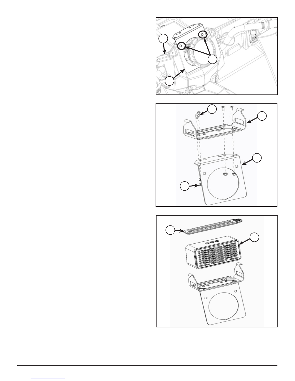
3. Align audio mount bracket (5) on the pod (B) and
use as template to drill the holes (E) of dia 5/16” as
shown in gure.
B
E
5
4. Fasten audio mount bracket (5) with audio mount
base (6) using four screws (10) and nyloc nuts (11).
Tighten screws until snug.
5. Snap t bluetooth speaker (4) and strap (8) on to the
audio mount assembly as shown in gure.
10
6
5
11
8
4
P/N 9925685 Rev 01 09/14 Page 3 of 8
Page 4

6. Align and Install audio mount assembly using two
tuok rivets (12) as shown in gure.
7. Use rubbing alcohol, pledge or other temporary
lubricant on the rubber gasket, both sides. Push
back bezel and cluster assembly (A) onto the pod
as shown in gure.
12
A
8. Re-install front pod (C) by fastening six screws removed in Step 2.
Tighten screws to torque 10 in-lbs. (1.13 Nm).
FOR SPORTSMAN 570 AND SPORTSMAN 570 TOURING
1. Place the vehicle in “PARK” and turn the key to “OFF” position. Remove the key from the vehicle.
2. Push out cluster with bezel assembly (F) by hand
from upper pod (G). If Bezel separates from gauge
don’t be alarmed, you will snap it back into place in
a later step. See gure.
F
G
P/N 9925685 Rev 01 09/14 Page 4 of 8
Page 5

3. If you cannot remove the cluster by hand, consider
removing the upper pod (G) by removing three
screws (H) as shown in gure.
4. Align audio mount bracket (7) with pod (G) and use
as template to drill the holes of dia 5/16” as shown
in gure.
G
H
7
G
5. Fasten audio mount bracket (7) with audio mount
base (6) using four screws (10) and nyloc nuts (11).
Tighten screws until snug.
10
6
7
11
P/N 9925685 Rev 01 09/14 Page 5 of 8
Page 6

6. Align and Install audio mount bracket assembly on
the pod using two tuok rivets (12) as shown in
gure.
7. Use rubbing alcohol, pledge or other temporary
lubricant on the rubber gasket, both sides.
Push back bezel and cluster assembly (F) to x onto
the upper pod as shown in gure.
12
8. Snap t bluetooth speaker (4) and strap (8) on to the
audio mount bracket assembly as shown in gure.
F
4
8
9. Re-install upper pod (G) by fastening three screws removed in Step 2.
Tighten screws to torque 10 in-lbs. (1.13 Nm).
P/N 9925685 Rev 01 09/14 Page 6 of 8
Page 7

FOR SPORTSMAN ACE MODELS (1.75” TUBE MOUNT)
1. Fasten plastic clamp (2) with audio mount base (6)
using four screws (10).
Tighten screws until snug.
2. Snap t bluetooth speaker (4) and strap (8) on to the
audio mount assembly (K) as shown.
10
6
2
8
4
3. Snap t bluetooth speaker assembly on to the
ROPS tube (1.75” Dia) at any required location.
NOTE: Ensure audio mount assembly installed on
ROPS tube will not obstruct vehicle operation and
driver’s vision.
K
P/N 9925685 Rev 01 09/14 Page 7 of 8
Page 8

FOR RANGER AND RZR MODELS (DASH MOUNT)
1. Place audio mount base (6) at required location on
the passenger side dash panel and use as template
to drill hole of dia 5/16” as shown in gure.
NOTE: Ensure audio mount assembly installed on
dash will not obstruct vehicle operation and driver’s
vision.
2. Mount audio mount base (6) with four tuok
rivets (12) on the dash panel as shown.
12
3. Snap t bluetooth speaker (4) and strap (8) on to the
audio mount base (6) as shown in gure.
8
4
P/N 9925685 Rev 01 09/14 Page 8 of 8
 Loading...