

Page 1
2015 600 / 800 RUSH
2015 600 / 800 SWITCHBACK
Snowmobile Owner's Manual
for Maintenance and Safety
Page 2
IMPORTANT NOTICE TO OWNER
For videos and more information
about a safe riding experience with
your Polaris vehicle, scan this QR
code with your smartphone.
Modifications to this snowmobile are not recommended
and may result in voided warranty coverage. Please
read the warranty section of this manual carefully.
WARNING
Read, understand, and follow all of the instructions and safety
precautions in this manual and on all product labels.
Failure to follow the safety precautions
could result in serious injury or death.
WARNING
The engine exhaust from this product contains chemicals
known to the State of California to cause cancer, birth defects
or other reproductive harm.
Page 3

WELCOME
Thank you for purchasing a POLARIS vehicle, and welcome to our
world-wide family of POLARIS enthusiasts. Be sure to visit us online at
www.polaris.com for the latest news, new product introductions,
upcoming events, career opportunities and more.
Here at POLARIS we proudly produce an exciting line of utility and
recreational products.
• Snowmobiles
• All-terrain vehicles (ATVs)
• Low emission vehicles (LEVs)
• RANGER® utility vehicles
•RZR® sport vehicles
• VICTORY® motorcycles
• GEM® vehicles
We believe POLARIS sets a standard of excellence for all utility and
recreational vehicles manufactured in the world today. Many years of
experience have gone into the engineering, design, and development of
your POLARIS vehicle, making it the finest machine we've ever
produced.
For safe and enjoyable operation of your vehicle, be sure to follow the
instructions and recommendations in this owner's manual. Your manual
contains instructions for minor maintenance, but information about
major repairs is outlined in the POLARIS Service Manual and should be
performed only by a factory certified Master Service Dealer® (MSD)
technician.
Your POLARIS dealer knows your vehicle best and is interested in your
total satisfaction. Be sure to return to your dealership for all of your
service needs during, and after, the warranty period.
1
Page 4

The following are trademarks of POLARIS Industries Inc.:
POLARIS® AXYS™ SWITCHBACK®
PERC® RUSH® SWITCHBACK ADVENTURE®
LOCK & RIDE®
Copyright 2014 POLARIS Industries Inc. All information contained within this
publication is based on the latest product information at the time of publication. Due to
constant improvements in the design and quality of production components, some minor
discrepancies may result between the actual vehicle and the information presented in
this publication. Depictions and/or procedures in this publication are intended for
reference use only. No liability can be accepted for omissions or inaccuracies. Any
reprinting or reuse of the depictions and/or procedures contained within, whether whole
or in part, is expressly prohibited.
The original instructions for this vehicle are in English. Other languages are provided as
translations of the original instructions.
Printed in U.S.A.
2015 600/800 AXYS Snowmobile Owner’s Manual
P/N 9925073
2
Page 5

TABLE OF CONTENTS
Introduction . . . . . . . . . . . . . . . . . . . . . . . . . . . . 5
This section contains helpful information for owners and drivers and
illustrates the location of important identification numbers that should
be recorded in the owner's manual.
Safety . . . . . . . . . . . . . . . . . . . . . . . . . . . . . . . . . 9
This section describes safe vehicle operation and identifies warning
labels and their locations.
Features . . . . . . . . . . . . . . . . . . . . . . . . . . . . . . 26
This section identifies the locations of your snowmobile's controls and
features.
The Perfect Fit . . . . . . . . . . . . . . . . . . . . . . . . . 51
This section includes a Suspension Quick Set-Up Guide and explains
how to make additional suspension adjustments for the perfect riding
experience.
Pre-Ride Inspections . . . . . . . . . . . . . . . . . . . . 66
This section explains procedures that must be performed before riding.
Operation . . . . . . . . . . . . . . . . . . . . . . . . . . . . . 73
This section explains proper engine break-in, operation of features and
general operating procedures.
Maintenance . . . . . . . . . . . . . . . . . . . . . . . . . . . 87
This section defines your role, and your dealer's role, in your
snowmobile's regular maintenance.
POLARIS Products. . . . . . . . . . . . . . . . . . . . . 137
Specifications. . . . . . . . . . . . . . . . . . . . . . . . . 138
Troubleshooting. . . . . . . . . . . . . . . . . . . . . . . 158
Warranty . . . . . . . . . . . . . . . . . . . . . . . . . . . . . 163
Maintenance Log . . . . . . . . . . . . . . . . . . . . . . 171
Index . . . . . . . . . . . . . . . . . . . . . . . . . . . . . . . . 174
3
Page 6

4
Page 7

INTRODUCTION
Important Notes for Owners and Drivers
After reading this manual, store it in the snowmobile for convenient
reference. It should remain with the snowmobile when the snowmobile
is sold.
Some of the illustrations and photos used in this manual are general
representations. Your model may differ.
Follow the maintenance program outlined in this manual. Preventive
maintenance ensures that critical components of the snowmobile are
inspected by your dealer at specific mileage intervals.
You and your dealer must complete the registration form included with
your snowmobile and forward it to us. This completed form is necessary
to ensure warranty coverage.
Protect and preserve your right to ride by joining your local trail riding
clubs.
When teaching inexperienced operators to ride, set up a predetermined
course for practice. Make sure they know how to drive and control the
snowmobile before allowing them to make longer trips. Teach them
proper snowmobile courtesy, and enroll them in driver’s training and
safety courses sponsored by local or state organizations.
5
Page 8

INTRODUCTION
Preservation of the Environment
POLARIS is committed to supporting an environmental education
campaign. We encourage state and provincial governments across the
snowbelt to adopt rigorous safety training programs that encourage
protection of our environment, including wildlife and vegetation.
Snowmobile clubs and other organizations are working together to
protect our environment. Please support their efforts and operate your
snowmobile with consideration for the protection and preservation of
our environment.
Noise Level
One of the most publicized issues about snowmobiles is noise. The
Society of Automotive Engineers (SAE), the standard-setting body for
snowmobile development, recommends that snowmobiles conform to
prescribed sound levels.
POLARIS snowmobiles are engineered to conform to these SAE
standards. Our muffler systems are designed to reduce noise levels and
must not be altered or removed. The sound of your snowmobile may not
be welcome to non-snowmobilers, so you have a responsibility to
operate your snowmobile with concern for others. We do our part by
manufacturing quieter machines; we ask your help to further reduce the
impact of noise by operating your snowmobile safely and responsibly.
Air Pollution
POLARIS engineers continuously investigate ways to reduce emission
levels of two-stroke engines. We expect our efforts to lead to the
reduction of potential air pollution.
In addition to our technological research, we encourage government
agencies, manufacturers, distributors, dealers, ecologists, and other
interested parties to work together to develop data on environmental
topics.
6
Page 9
INTRODUCTION
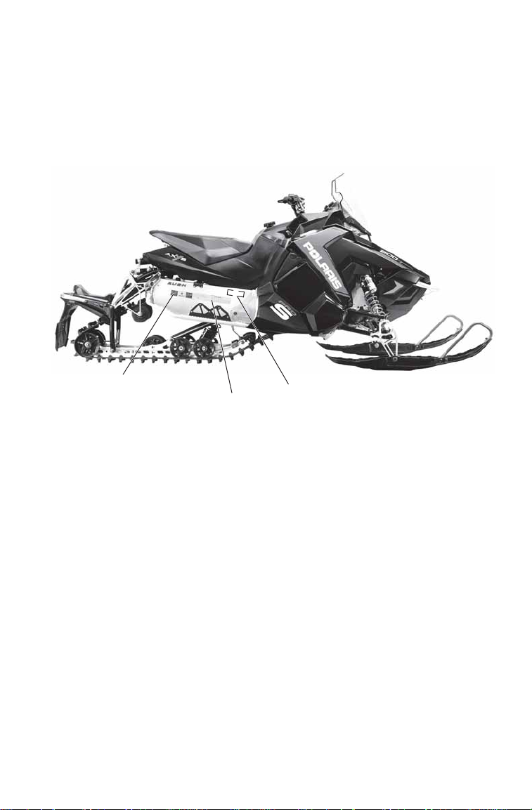
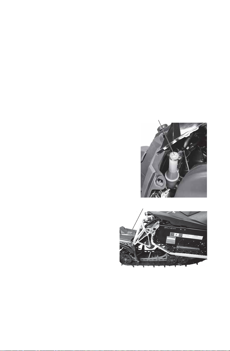
Vehicle Identification Numbers
Record your snowmobile's identification numbers and key number in
the spaces provided.
NOTE: The Vehicle Identification Number (VIN) is stamped into the side of the
tunnel and printed on the tunnel VIN label.
Certification Label
Tunnel VIN
Vehicle Model Number: ___________________________________________________
Tunnel VIN (right side of tunnel): ____________________________________________
Engine Serial Number (on recoil housing): _____________________________________
Key Number: _____________________ _______________________________________
NOTICE: If installing an aftermarket tunnel wrap, do not cover the tunnel
certification, tunnel VIN or emissions certification labels with the wrap.
If the tunnel wrap doesn’t provide an opening for these labels, remove
the section of wrap where the labels are located.
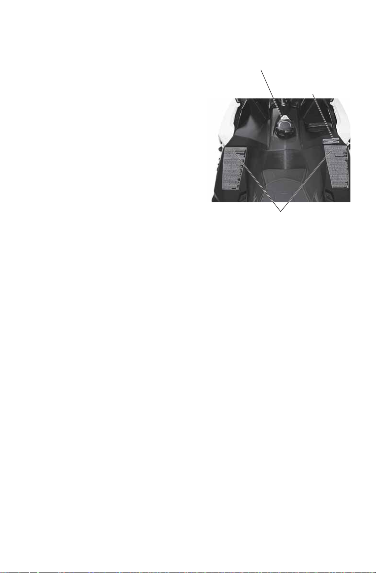
Emissions Certification Label
7
Page 10
INTRODUCTION
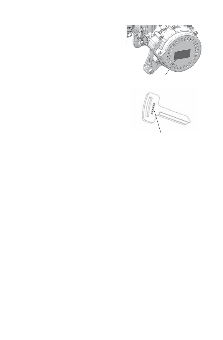
Engine Serial Number
Key Identification
Number
Engine Serial Number
The engine serial number is located
on the identification label on the
engine recoil cover.
Key Identification
The ignition keys are etched with an
identification number. Remove the
spare key and store it in a safe place.
Your key can be duplicated only by
mating a POLARIS key blank using
the same identification number with
one of your existing keys, so if both
keys are lost, the ignition switch
assembly must be replaced.
8
Page 11

SAFETY
Operator Safety
The following signal words and symbols appear throughout this manual
and on your vehicle. Your safety is involved when these words and
symbols are used. Become familiar with their meanings before reading
the manual.
The safety alert symbol indicates a potential personal injury hazard.
DANGER
A DANGER indicates a hazardous situation that, if not avoided, will result in
death or serious injury.
WARNING
A WARNING indicates a hazardous situation that, if not avoided, could result in
death or serious injury.
CAUTION
A CAUTION indicates a hazardous situation that, if not avoided, could result in
minor or moderate injury.
NOTICE
A NOTICE indicates a situation that could result in property damage.
The Prohibition Safety Sign indicates an action NOT to take in order
to avoid a hazard.
The Mandatory Action Sign indicates an action that NEEDS to be
taken to avoid a hazard.
9
Page 12

SAFETY
WARNING
Operator Safety
Follow the recommended maintenance program beginning on page 88
of this manual to ensure that all critical components on the snowmobile
are thoroughly inspected by your dealer at specific mileage intervals.
Driving a snowmobile requires your full attention. DO NOT drink alcohol or use
drugs or medications before or while driving or riding as a passenger. They will
reduce your alertness and slow your reaction time.
Snowmobiles are capable of traveling at high speeds. Use extra caution to
ensure operator safety. Make sure your snowmobile is in excellent operating
condition at all times. Always check major and vital safety components before
every ride.
All POLARIS snowmobiles are designed and tested to provide safe operation
when used as directed. Failure of critical machine components may result from
operation with any modifications, especially those that increase speed or power.
DO NOT MODIFY YOUR MACHINE. The snowmobile may become aerodynamically unstable at speeds higher than those for which it is designed. Loss of
control may occur at higher speeds. Modifications may also create a safety hazard and lead to bodily injury.
The warranty on your entire machine is terminated if any equipment has been
added, or any modifications have been made, to increase the speed or power of
the snowmobile.
10
Page 13

SAFETY
NO
STEP
Operator Safety
Stay Clear of Track
Your snowmobile is propelled by a revolving track that must be partially
exposed for proper operation. Do not stand on the plastic flap.
WARNING! Serious injuries may result if
hands, feet, or clothing become entangled
in the track. Be alert when riding, and
remain properly seated to stay clear of the
track. Never hold the snowmobile up or
stand behind it while warming up the track.
A loose track or flying debris could cause
serious injury or death. We recommend
having your dealer perform all track service
and alignment procedures.
Stay Clear of Engine
Never attempt adjustments with the engine running. Stop the engine
before opening a side panel. Always ensure that the hood and side
panels are installed and securely latched before starting the engine.
WARNING! Serious injury can occur if fingers or clothing contact the moving
parts of an engine. Always stop the engine before attempting adjustments.
Riding Position
Operating a snowmobile requires skill and balance for proper control.
Rider positions may vary with experience and the features available on
some snowmobiles, but under many conditions, the proper position is to
be seated with both feet on the running boards and both hands on the
handlebar grips for proper throttle, brake and steering control.
WARNING! Improper riding position may reduce control and could result in
serious injury or death. Always ride in a position that allows for control of your
vehicle.
11
Page 14
SAFETY
Operator Safety
Riding Apparel
Helmet
Wearing a helmet can prevent a severe head injury. Whenever riding a
POLARIS vehicle, always wear a helmet that meets or exceeds
established safety standards.
Approved helmets in the USA and Canada bear a U.S. Department of
Transportation (DOT) label.
Approved helmets in Europe, Asia and Oceania
bear the ECE 22.05 label. The ECE mark consists
of a circle surrounding the letter E, followed by the
distinguishing number of the country which has
granted approval. The approval number and serial
number will also be displayed on the label.
Eye Protection
Do not depend on eyeglasses or sunglasses for eye protection.
Whenever riding a POLARIS vehicle, always wear shatterproof goggles
or use a shatterproof helmet face shield. POLARIS recommends
wearing approved Personal Protective Equipment (PPE) bearing
markings such as VESC 8, V-8, Z87.1, or CE. Make sure protective eye
wear is kept clean.
4
E
051039
0006.31
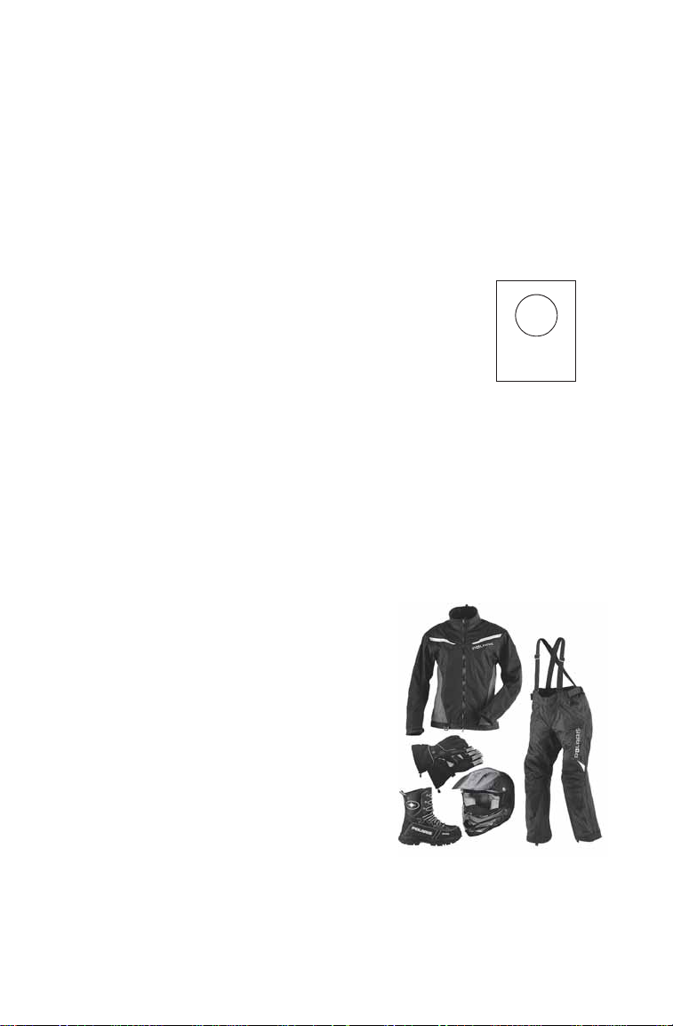
Clothing
Be prepared, be warm and be
comfortable when riding. Be aware of
the weather forecast, especially the
windchill, and dress accordingly. See
the chart on page 21.
WARNING! Avoid wearing loose clothing
or long scarves, which can become
entangled in moving parts and cause
serious injury. Always wear an approved
helmet and eye protection.
12
Page 15

SAFETY
Operator Safety
Disabled Operators
Safe operation of this rider-active vehicle requires good judgement and
physical skills. Operators with cognitive or physical disabilities have an
increased risk of loss of control, which could result in serious injury or
death.
Survival Preparation
For your safety, always ride in a group of other snowmobilers. Always
tell someone where you're going and how long you expect to be gone. If
it isn't possible to ride with others, and you must travel into remote
areas, always carry survival equipment that's appropriate to the
conditions you may encounter. Such equipment may include, but is not
limited to: extra clothing, a sleeping bag, a flashlight, food and water, a
signaling mirror, a means of building a fire and a two-way radio or
cellular telephone.
Always carry the owner’s manual on your snowmobile. For added
protection, purchase and carry the following items on your snowmobile
as well:
• Spare Drive Belt • Winter Survival Kit
• Extra Set of Spark Plugs • Trail Map
•Tow Rope •First Aid Kit
• Extra Oil • Tool Kit
• Fuel Deicer
13
Page 16

SAFETY
Operator Safety
Rider Capacity
This snowmobile is designed for a single rider only. Never carry a
passenger on this snowmobile.
Excessive Speed
WARNING! High speed driving, especially at night, could result in serious injury
or death. Always reduce speed when driving at night or in inclement weather.
Always observe all state and local laws governing snowmobile
operation and speed limits. Always be alert and pay attention to the trail
ahead. If your speed is 40 MPH (64 km/h), your snowmobile is traveling
about 60 feet (18 m) per second. If you look back for only two seconds,
your snowmobile will travel about 120 feet (36 m). If your speed is 60
MPH (96 km/h), your snowmobile will travel about 180 feet (55 m) in
two seconds.
Traveling at night requires extra caution. Check headlight and taillight
to ensure proper operation, and don’t over-drive your headlight beam.
Always be able to bring your snowmobile to a stop in the distance
illuminated by the headlight.
14
Page 17

SAFETY
RR
Operator Safety
Driver Awareness
Slow down when traveling near poles, posts, or other obstacles. Be
especially alert if you're snowmobiling after dark. Always be on the
alert for wire fences. Single strands are especially dangerous, since there
may be a great distance between posts. Guy wires on utility poles are
also difficult to distinguish.
Make sure the way is clear before crossing
railroads and other roads and highways. The
noise of your snowmobile will drown out the
sound of approaching vehicles. Look ahead,
behind, and to both sides before turning or
crossing railroad tracks or highways. Steep
embankments may also hide your view.
Always leave yourself a way out.
Variances in snow depth and/or water currents may result in uneven ice
thickness. You may drown if you break through the ice. Never travel on
frozen bodies of water unless you have first verified that the ice is
sufficiently thick to support the weight and moving force of the
snowmobile, you and your cargo, together with any other vehicles in
your party . Always check with local authorities and residents to confirm
ice conditions and thickness over your entire route. Snowmobile
operators assume all risk associated with ice conditions on frozen bodies
of water.
When teaching inexperienced operators to ride, set up a predetermined
course for practice. Make sure they know how to drive and control the
snowmobile before allowing them to make longer trips. Teach them
proper snowmobile courtesy , and enroll them in driver's training and
safety courses.
15
Page 18

SAFETY
Operator Safety
Avalanches
Snowmobilers should always be properly
trained and equipped before traveling in
mountainous terrain:
• Take an avalanche class
• Travel with experienced people
• Travel on designated trails
• Make sure each person is equipped
with a shovel, probe and avalanche
beacon.
Y o u don’t have to be snowmobiling on a slope for an avalanche to occur .
Be aware that all of the snow is connected. You may be riding on a flat
slope or snow covered road, but if the snowpack above is unstable
enough you can trigger an avalanche on a steeper slope above you.
Always be aware of snow conditions above you as you travel in
mountainous terrain.
Before riding in mountainous terrain, call or log on to your local
avalanche advisory to get current weather and snow stability
information.
For more information about avalanche training and avalanche
conditions, contact local law enforcement in your area, or visit the
American and Canadian online avalanche centers at
www.avalanche.org.
16
Page 19

SAFETY
Operator Safety
Ice and Snow Build-up
WARNING! Ice and snow build-up may interfere with the steering of your
snowmobile, resulting in serious injury or death. Keep the underhood area free
of snow and ice.
Before driving, manually turn the skis to the left and right to be sure ice
and snow are not interfering with full left and right steering. If difficulty
is encountered, remove ice and snow build-up that may be obstructing
the steering linkage.
Driving on Slippery Surfaces
WARNING! Never attempt an abrupt change of direction when operating on
slippery surfaces. Proceed slowly and use extra caution. Driving on ice or hardpacked snow reduces steering and braking control, which may result in loss of
control and serious injury or death. Slow down and use extra caution when
operating on slippery surfaces.
Inadequate Snow Conditions
Since snow provides the only lubrication for the power slide suspension
and, on liquid cooled models, cooling for the engine, adequate snow
cover is a requirement for operation of your snowmobile.
NOTICE: Driving in too little snow will result in excessive wear and damage to
WARNING! Inadequate cooling and lubrication will lead to overheating of the
slide rail and track, causing premature wear, damage and failure, which can
result in serious injury. Reduce speeds and frequently drive into fresh snow to
allow adequate cooling and polishing of the slide rail and track surfaces. Avoid
operating for prolonged periods on ice, hard-packed surfaces or roads.
the slide rail, track and/or engine.
Operating in Deep Snow
If the snowmobile becomes stuck in snow, clear the running board area
of snow, then step down the snow in front of the snowmobile so that
when the throttle is opened, the snowmobile will be able to climb up and
over the snow.
17
Page 20

SAFETY
Operator Safety
Driving Downhill
When riding downhill, shift your weight to the rear of the snowmobile
and reduce your speed to a minimum. Apply just enough throttle to keep
the clutch engaged, allowing the engine's compression to help slow the
snowmobile and keep it from rolling freely downhill.
WARNING! When driving on long downhill stretches, pump the brakes. Riding
the brakes may cause the brake system to overheat, which may result in brake
failure. Excessive or repetitive use of the brakes for high speed stops will also
cause an overheated brake system. This condition may lead to a sudden loss of
brakes and/or fire and may result in serious injury or death.
Driving in Hilly Terrain
WARNING! Climbing a hill or crossi ng the face of a slope may result in loss of
balance and snowmobile rollover, causing serious injury or death. Use caution
and good judgement when driving in hilly terrain.
Use extra caution when operating in hilly terrain. If climbing a hill is
unavoidable, keep your weight low and forward. If you must cross the
face of a slope, keep your weight on the uphill side of the snowmobile to
maintain proper balance and avoid possible roll-over.
Slow down when reaching the crest of a hill. Be prepared to react to
obstacles, sharp drops or other people or vehicles that may be on the
other side of the hill.
If you’re unable to continue up a hill, turn the snowmobile downhill
before it loses momentum. If this isn't possible, spin the track just
enough to dig in to prevent it from rolling back down the hill. Stop the
engine and set the parking brake (if equipped). Keeping away from the
downhill side of the snowmobile, pull the rear of the snowmobile
around and point the front end and skis downhill. Remount the
snowmobile, restart the engine, release the parking brake, and descend
the hill carefully.
18
Page 21

SAFETY
Operator Safety
Drive Belt
Do not operate the engine with the drive belt removed.
Any servicing that requires operation without a belt must be performed
by your dealer.
NOTICE: Operation of the engine with the belt removed may result in injury or
Intake Silencer
Do not operate the engine with the intake silencer or filter removed.
NOTICE: Damage to the engine may occur if the intake silencer or filter are
Clutches
Do not attempt to service the clutches.
All clutch service must be performed by your dealer. The clutch is a
complex mechanism that rotates at high speeds. Each clutch is
dynamically balanced before installation. Any tampering may disrupt
this precision balancing and create an unstable condition.
Cold Weather Drive-Away
Whenever your snowmobile has been parked for a length of time,
especially overnight, always make sure the skis and track are loosened
from ice and snow before attempting to drive. Apply the throttle with
enough authority to put the snowmobile into motion, but always operate
within safety limits.
damage to the engine.
removed.
Maneuverability
While much control and maneuverability is achieved through the
steering system and skis, maximum control is achieved by the shifting
of your body weight. Maneuverability will change for lighter operators
or snowmobiles designed to carry a load.
19
Page 22

SAFETY
Operator Safety
Driving Responsibly
Every snowmobile handles differently, and even the most docile
conditions may become dangerous if operators drive improperly. If
you're new to snowmobiling, acquaint yourself with the snowmobile
and with what it will and won't do under various conditions. Even
seasoned drivers should spend some time getting the feel for a
snowmobile before attempting ambitious maneuvers.
• A snowmobile depends on the rider’s body position for proper
balance in executing turns, traversing hills, etc. Always start on a
smooth, level area to begin building your operating experience.
• Before allowing someone else to use your snowmobile, know the
extent of their operating skills. Check to see if they've taken a
snowmobile safety course and have an operator's certificate. For their
protection, as well as yours, make sure they take a snowmobile safety
course. Everyone can benefit from the course.
• Don't “jump” your snowmobile over large drifts or similar terrain.
Jumping may injure your back because of spinal compression that
could occur when the snowmobile impacts the ground. The seat and
suspension of your snowmobile have been designed to provide
protection under normal riding conditions. Your snowmobile is not
intended for this kind of use.
• Be courteous to oncoming traffic by dimming your headlights and
reducing your speed.
• When traveling in a group of snowmobiles, don't tailgate (follow too
closely). Leave enough distance between snowmobiles to provide
ample stopping room and to provide protection from flying snow and
debris. Allow even more distance when driving on slippery surfaces
or when driving in darkness or other low visibility conditions. Be
aware of any snowmobile traffic around your vehicle. Drive
defensively to avoid accidents.
• Remove the key from the ignition when you leave the snowmobile
unattended.
20
Page 23
SAFETY
Operator Safety
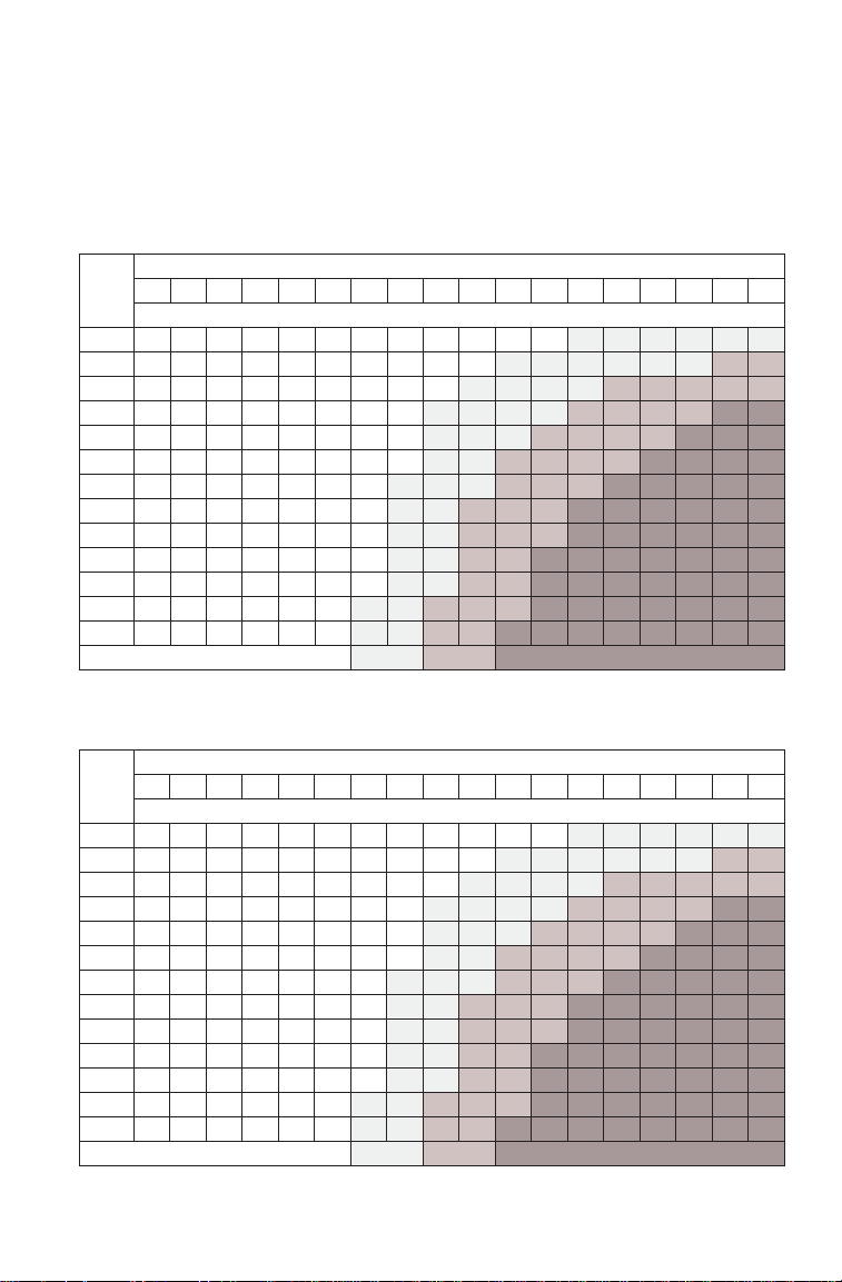
Windchill/Temperature Charts
The following information is provided to help you determine when
temperatures become dangerous for riding.
WINDCHILL CHART (°F)
Wind
Speed
40 35 30 25 20 15 10 5 0 -5 -10 -15 -20 -25 -30 -35 -40 -45
in
MPH
Calm 40 35 30 25 20 15 10 5 0 -5 -10 -15
5 3631251913 7 1 -5-11-16
10 34 27 21 15 9 3 -4 -10 -16
15 32 25 19 13 6 0 -7 -13
20 30 24 17 11 4 -2 -9 -15
25 29 23 16 9 3 -4 -11 -17
30 28 22 15 8 1 -5 -12
35 28 21 14 7 0 -7 -14
40 27 20 13 6 -1 -8 -15
45 26 19 12 5 -2 -9 -16
50 26 19 12 4 -3 -10 -17
55 25 18 11 4 -3 -11
60 25 17 10 3 -4 -11
Frostbite in >>
Actual Thermometer Reading (°F)
Equivalent Temperature (°F)
-20 -25 -30 -35 -40 -45
-22 -28 -34 -40 -46 -52 -57 -63
-22 -28 -35 -41 -47 -53 -59 -66 -72
-19 -26 -32 -39 -45 -51 -58 -64 -71 -77
-22 -29 -35 -42 -48 -55 -61 -68 -74 -81
-24 -31 -37 -44 -51 -58 -64 -71 -78 -84
-19 -26 -33 -39 -46 -53 -60 -67 -73 -80 -87
-21 -27 -34 -41 -48 -55 -62 -69 -76 -82 -89
-22 -29 -36 -43 -50 -57 -64 -71 -78 -84 -91
-23 -30 -37 -44 -51 -58 -65 -72 -79 -86 -93
-24 -31 -38 -45 -52 -60 -67 -74 -81 -88 -95
-18 -25 -32 -39 -46 -54 -61 -68 -75 -82 -89 -97
-19 -26 -33 -40 -48 -55 -62 -69 -76 -84 -91 -98
30 min. 10 min. 5 min.
WINDCHILL CHART (°C)
Wind
Speed
5 2 -1 -4 -7 -10 -13 -16 -19 -22 -25 -28 -31 -34 -37 -40 -43 -46
in
Km/h
Calm 5 2 -1 -4 -7 -10 -13 -16 -19 -22 -25 -28
8 3 0 -4 -7 -11 -14 -18 -22 -25 -29
16 2 -2 -6 -10 -13 -17 -21 -24 -28
24 1 -3 -7 -11 -15 -19 -22 -26
32 0 -4 -8 -12 -16 -20 -24 -28
40 -1 -5 -9 -13 -17 -21 -25 -29
48 -1 -5 -9 -13 -18 -22 -26
56 -2 -6 -10 -14 -18 -22 -26
64 -2 -6 -10 -15 -19 -23 -27
72 -2 -7 -11 -15 -19 -23 -28
80 -3 -7 -11 -15 -20 -24 -28
88 -3 -7 -12 -16 -20 -24
96 -3 -8 -12 -16 -21 -25
Frostbite in >>
Actual Thermometer Reading (°C)
Equivalent Temperature (°C)
-32 -36 -39 -43 -46 -50 -53 -57
-32 -36 -39 -43 -47 -50 -54 -58 -62
-30 -34 -38 -42 -45 -49 -53 -57 -61 -65
-32 -36 -39 -43 -47 -51 -55 -59 -63 -67
-33 -37 -41 -45 -49 -53 -57 -61 -65 -69
-30 -34 -38 -42 -46 -50 -54 -58 -62 -66 -70
-31 -35 -39 -43 -47 -51 -55 -59 -64 -68 -72
-31 -35 -40 -44 -48 -52 -56 -61 -65 -69 -73
-32 -36 -40 -45 -49 -53 -57 -61 -66 -70 -74
-33 -37 -41 -45 -50 -54 -58 -62 -67 -71 -75
-29 -33 -37 -42 -46 -50 -55 -59 -63 -67 -72 -76
-29 -34 -38 -42 -47 -51 -55 -60 -64 -68 -73 -77
30 min. 10 min. 5 mi n.
-31 -34 -37 -40 -43 -46
21
Page 24
SAFETY
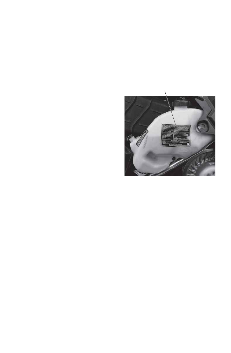
Pressure Cap
Warning
Safety Labels and Locations
W arning labels have been placed on the snowmobile for your protection.
Read and follow the instructions of the labels and other warnings on the
snowmobile carefully . If any of the labels depicted in this manual differ
from the labels on your snowmobile, always read and follow the
instructions of the labels on the snowmobile.
If any label becomes illegible or comes off, contact your POLARIS
dealer to purchase a replacement. Replacement safety labels are
provided by POLARIS at no charge. The part number is printed on the
label.
Pressure Cap Warning
This warning label is found on the
pressure cap of applicable liquid
cooled models:
WARNING
Do not open hot. T est or replace
when changing coolant. Press
down and turn to release cap.
13 PSI
7170063
Track Warning
WARNING
Stay clear of track. Do not sit on
seat back. Entanglement with
the track or a fall from seat back
may result in severe injury or
death.
22
Track Warning
7175974
Page 25
Safety Labels and Locations
Reverse Warning
Fuel Recommendation Label
No Passenger
Warning
No Passenger Warning
WARNING
This vehicle is designed for
operator only. NO
PASSENGER.
7181012
Fuel Recommendation
Label
91+ Octane without Ethanol.
For maximum performance see
decal on left hand side panel
for setting.
7181061
Reverse Warning
WARNING
Reverse operation, even at low speeds, can cause loss of control
resulting in serious injury or death. To avoid loss of control,
always:
• Look behind before and wh ile ba cking up.
• Avoid sharp turns.
• Shift to or from reverse only when stopped.
• Apply throttle slowly.
NOTE: For more information, see Owner’s Manual.
If electric reverse:
• Machine stopped and engine at idle, push yellow button on LH
control to reverse. Flashing light on dash indicates reverse
operation.
• Push button again to return to forward.
SAFETY
7176779
23
Page 26

SAFETY
Safety Labels and Locations
Operation Warning
WARNING
• To avoid serious injury or death,
read and understand all warnings
and the Owner's Manual before
operation. If manual is missing,
contact a POLARIS dealer for a
replacement.
• This vehicle is capable of high
speeds. Buried objects or uneven
terrain can cause loss of control.
Reduce speed and use extreme
caution when operating in
unfamiliar terrain.
• Excessive speed, especially at night or with limited visibility, can result
in insufficient time for you to react to terrain changes, to avoid
unexpected obstacles, or to stop safely.
• Never consume alcohol or drugs before or while operating this vehicle.
• In an emergency, push down the Auxiliary Shut-Off Switch, located on
the top of the throttle control assembly, to stop the engine. Then pull the
brake lever to stop.
• Always wear an approved helmet, eye protection, and adequate clothing
while operating this vehicle.
• This vehicle is designed for adult use only. Check local laws for age
requirements.
• When operating with a passenger (on approved models only) reduce
speed and allow extra space for steering and stopping. A passenger
reduces your ability to control the vehicle.
• When operating on hard-packed snow, ice, or when crossing roads,
steering and braking ability are greatly reduced. Reduce speed and
allow extra space to turn or stop.
• To maintain vehicle control on ice or hard-packed surfaces, you should
have a proper balance of ski carbides to track studs. See Owner's
Manual for proper use of traction products.
• Repeated stops from high speed may cause fading or sudden loss of
braking ability.
• Parking brake may relax when used for long periods. Do not leave brake
engaged for more than five minutes.
• Before starting engine, check throttle, brake, and steering for pr oper
operation. Make sure hood and side panels are latched. Be seated and
in position to control the vehicle.
Oil injection system: Use unmixed fuel only. Check oil level when
refueling.
Operation Warning
7176779
24
Page 27
SAFETY
Clutch Warning/Belt Removal
Safety Labels and Locations
Clutch Warning/Belt Removal
WARNING
Do not operate engine with hood or side panels open. Do not attempt
adjustment with engine running. Do not operate engine with the clutch
guard removed. Never run engine with drive belt removed. Never service
clutches yourself - See your dealer.
Belt Removal - All Units
1. For electric reverse models,
engine must be stopped in
forward to allow clutch
opening
2. Install L-wrench from fender
into the open threaded hole in
the driven clutch.
3. Turn the L-wrench clockwise
to open the sheaves and
replace the belt.
4. Return the L-wrench to the
fender.
Note: See owners manual for
sheave width adjustment
procedure.
7181093
25
Page 28
FEATURES
8
13
5
7
12
11
2
1
4
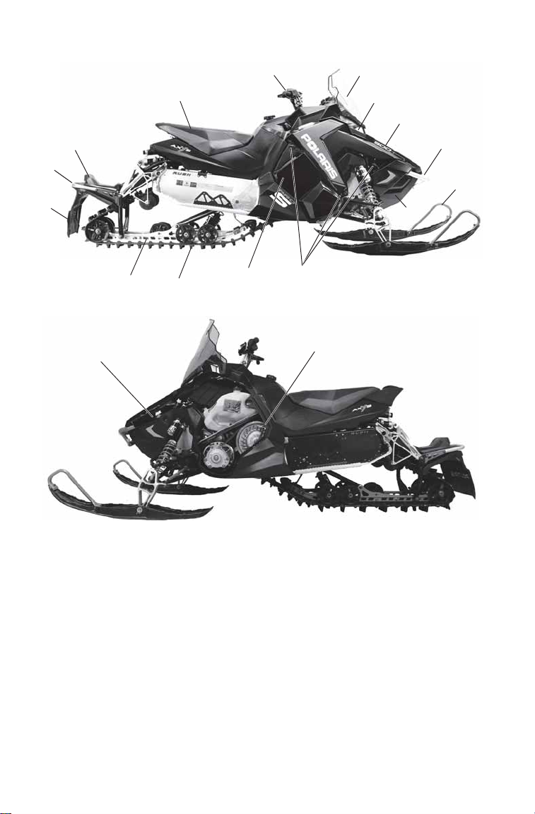
1. Nosepan
2. Skis
3. Front Bumper
4. Hood
5. Headlight
6. Windshield (accessory)
7. Handlebar
8. Operator Seat
9. Taillight
10. Rear Bumper
11. Snow Flap
12. Suspension
13. Track
14. Side Panel
15. Side Panel Fasteners
16. Tool Kit (Inside engine
compartment)
17. L-Wrench
15
14
3
6
9
10
16
17
26
Page 29
FEATURES
10
8
9
11
12
7
1
2
1
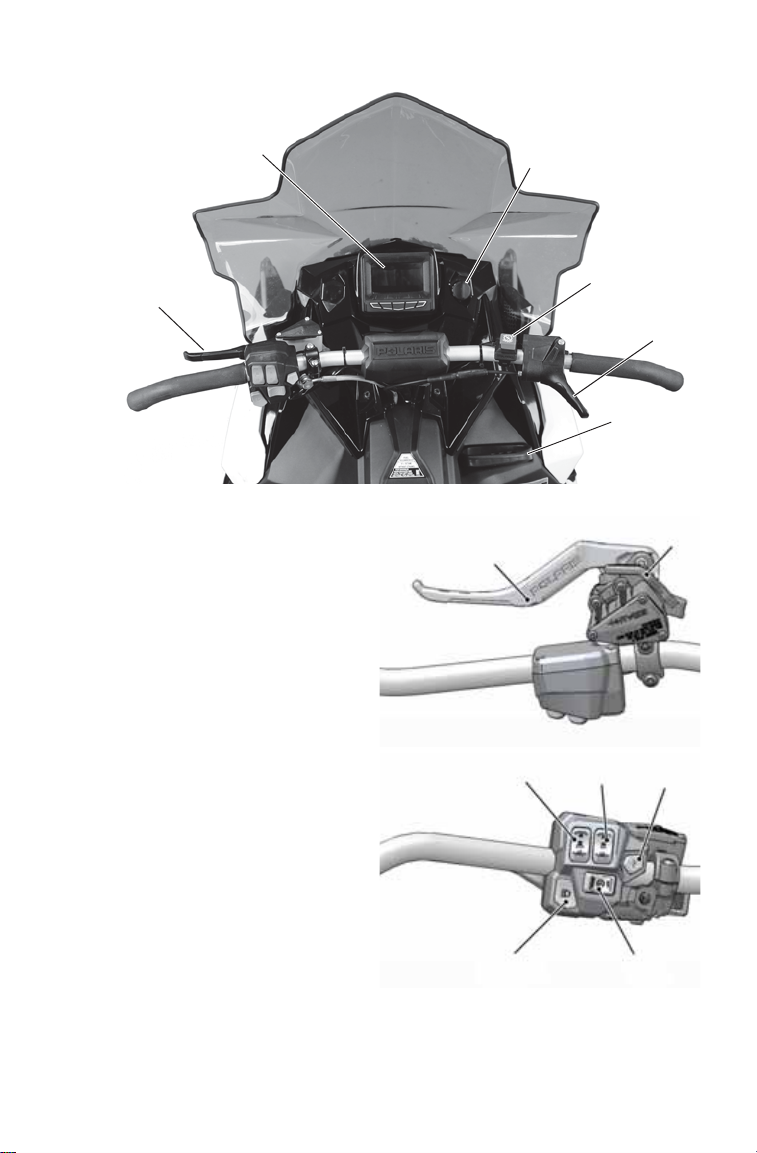
1. Brake Lever
2. Instrument Cluster
(Interactive Digital Display
shown)
3. Ignition Switch
4. Engine Stop Switch
5. Throttle Control
6. Recoil Starter Handle
7. Parking Brake Lock
8. Handlebar Grip Warmer
Switch
9. Thumbwarmer Switch
10. POLARIS Electronic Reverse
(PERC) Button
11. Mode/Set Switch
12. Headlight Dimmer Switch
3
4
5
6
27
Page 30
FEATURES
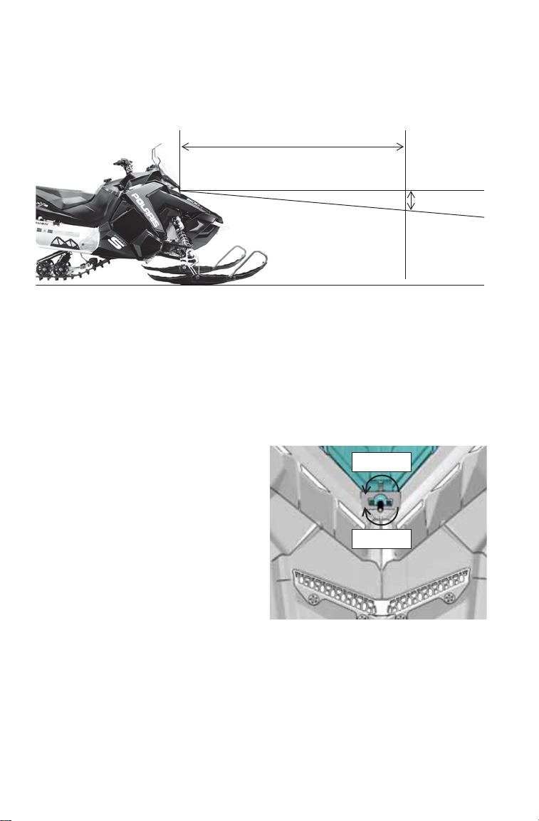
2 in. (5 cm)
Lamp Center Height
25 ft. (7.6 m)
X
Adjustable Headlight
The headlight can be adjusted for vertical aim using the following
procedure.
1. In a well-ventilated area, position the snowmobile on a level surface
with the headlight approximately 25 feet (7.6 m) from a wall.
2. Place the rider or the approximate weight of the rider on the seat or
tunnel floorboards.
3. Measure the distance from the floor to the center of the headlight
and make a mark on the wall at the same height.
4. Start the engine. Move the headlight switch to high beam.
5. Observe the headlight aim on
the wall. The most intense part
of the headlight beam should be
two inches (5 cm) below the
mark on the wall.
6. If adjustment is necessary,
access the headlight adjuster
knob through the left side
panel. Turn the adjuster knob
clockwise to lower the beam.
Turn the adjuster counterclockwise to raise the beam.
Raise
Lower
28
Page 31

Heated Storage Compartment
Heated Storage
(if equipped)
The storage compartment on
the top of the console is
heated by engine
compartment heat. This
compartment can be used to
warm gloves or defog
goggles.
12-Volt Receptacle
If equipped, the 12-volt DC
receptacle is located on the
console next to the
instrument cluster. If not
equipped, the receptacle can
be installed as an accessory.
The 12-volt receptacle is
protected by a 2 AMP fuse.
FEATURES
12-Volt Receptacle
(if equipped)
29
Page 32

FEATURES
Saddlebags
Some snowmobiles are equipped
with saddlebags. LOCK & RIDE
saddlebags can be added as an
accessory on other models. Please
see your POLARIS dealer for
more information.
Three (3) locking plungers secure
each saddlebag to the rear cargo
rack. To remove a saddlebag,
open each plunger latch, then pull
the bag away from the rack.
When reinstalling the saddlebags,
always make sure the locking
plungers are secured before
operating.
30
Page 33

FEATURES
Fuel
Selection
Fuel Type Selection
Whenever using ethanol, MTBE or other forms of oxygenated gasoline,
the fuel type designation setting must be changed to “Eth” in the gauge.
When using the recommended 91 non-ethanol gasoline, always select
the “91-non” setting. Whenever in doubt of your fuel purchase, use the
“Eth” setting as a safeguard.
Interactive Digital Display (IDD)
If your model is
equipped with the
interactive digital display
(IDD), please see your
IDD Owner’s Manual for
fuel type selection
procedures.
Standard Instrument Cluster
Use the following procedure to change the fuel type designation in the
standard instrument cluster. Refer to the fuel type selection label located
inside the left side panel.
Fuel Type Selection Label
1. Start the engine. Lock the parking brake.
2. Press and release the
SELECT button or SET
switch until “FUEL” is
displayed in the lower
section of the gauge.
3. Press and hold the
SELECT button or SET
switch until the desired
fuel type is displayed in
the center of the screen.
Step 2 Step 3
31
Page 34

FEATURES
Standard Instrument Cluster
Interactive Digital Display (IDD)
Detonation Elimination Technology (DET)
The DET system prevents damage to the engine from detonation by
entering an engine protection mode whenever the DET system is active.
When excessive detonation is detected, the check engine light will
illuminate. You may notice decreased engine performance and RPM
when the DET system is activated. In most cases this is temporary and
no action is required. The engine will return to its normal performance
automatically.
If severe detonation occurs, the check engine light will begin to flash
steadily.
• The standard gauge will display “dET”.
• The IDD will display “Detonation Detected - MAG (or PTO)”.
The engine will enter a limp home mode and engine speed will be
limited to 6500 RPM. The engine will remain in this mode until it is
shut down and restarted.
Check Engine Light Indicates
Solid or Flickering Excessive detonation detected
Steady Flashing Severe detonation detected, RPM will be limited
32
Page 35

FEATURES
Detonation Elimination Technology (DET)
The most likely causes of severe detonation are outlined in the
troubleshooting table below.
DET Troubleshooting
Cause of DET Activation Solution
Poor quality fuel Replace with higher quality fuel
Incorrect ethanol/non-ethanol fuel
type setting
Low fuel/no fuel in tank Refuel with recommended fuel
Water in fuel Replace with recommended fuel
Plugged fuel filter or tank pick-up sock See your POLARIS dealer for service
Alcohol-based fuel additive used with
Ethanol fuel
Improper engine modifications Do not modify the engine
Verify correct fuel type setting on
gauge
Do not add deicers or additives that
contain any form of alcohol while
using up to 10% ethanol fuel
33
Page 36

FEATURES
Engine Overheat Indicators
Over-Temperature Indicator (Standard Cluster)
The over-temperature
indicator on the standard
instrument cluster will
illuminate when the engine is
overheating. Take action to
cool the engine. See page 35.
The indicator will flash when
engine temperature reaches
critical levels. Stop the
engine immediately.
Overheat Warning (IDD)
The engine temperature scale
at the right side of the IDD
screen changes to RED and
the check engine temperature
indicator at the top left of the
screen illuminates when the
engine is overheating. Take
action to cool the engine. See
page 35.
The indicator will flash when engine temperature reaches critical levels.
Stop the engine immediately.
Please see your IDD Owner’s Manual for more information.
Flashing Indicator
Flashing indicators indicate continued operation could result in serious
engine damage. The engine management system will automatically
reduce engine power and create a misfire condition. Stop the engine
immediately. Allow the engine to cool down.
NOTE: If engine overheating seems to be caused by something other than
34
poor cooling conditions, see your dealer for service.
Page 37

FEATURES
Engine Overheat Indicators
Engine-Cooling Actions
If the engine is overheating, promptly take action to cool the engine.
• Drive in loose snow.
• V iew the coolant level. Do not open the pr essur e cap while the engine
is hot. Add coolant if the level is low.
• Stop the engine and allow it to cool down.
NOTICE: If you must continue to operate while the indicator light is illuminated,
Security System (Ignition Lock System)
Your snowmobile has an optional security function that can be activated
by an authorized POLARIS dealer. If you have this feature activated,
you can lock the ignition to prevent unauthorized use when leaving the
snowmobile unattended. A locked system will limit engine speed to
3000 RPM, which prevents clutch engagement, and the snowmobile
will not move when throttle is applied.
If you wish to use this system, see page 43 for security system activation
and operating instructions (standard instrument cluster). If your model is
equipped with the Interactive Digital Display (IDD), please see the IDD
Owner’s Manual provided with your snowmobile.
drive slowly and stop the engine frequently to allow it to cool down.
35
Page 38

FEATURES
Rider Information
Center
Check Engine
Indicator
High Beam
Indicator
Low Oil
Indicator
Over-Tem-
perature Indi-
cator
Parking Brake
Indicator
Reverse
Indicator
MODE
Button
SELECT
Button
Standard Instrument Cluster
The instrument cluster contains
indicator lights and the rider
information center. The information
center can be controlled by either the
MODE and SELECT buttons on the
instrument cluster or by the MODE/
SET switch on the left handlebar.
NOTICE: Certain products will damage
CAUTION! The speedometer may give wrong values at the existence of
electromagnetic radiation >= 10 V/m.
the lens and other plastic
surfaces. Do not use alcohol to
clean the instrument cluster.
Immediately clean off any
gasoline that splashes on the
instrument cluster.
MODE SET
36
Page 39

FEATURES
Standard Instrument Cluster
Indicators
Check Engine Indicator
This indicator appears if an EFI-related fault occurs. Do not operate the
snowmobile if this warning appears. Serious engine damage could
result. See your dealer. See page 92 for diagnostic code definitions.
Over-Temperature Indicator
This indicator illuminates to alert the operator that the engine is
overheating. The operator should take action to cool the engine. If the
indicator flashes, continued operation could result in serious engine
damage. Stop the engine immediately.
Low Oil Indicator
The low oil indicator light may flicker at times due to oil movement in
the bottle, but when the light comes on and remains on, add the
recommended oil before further operation. See page 80.
High Beam Indicator
The high beam indicator illuminates when the lights are set to high
beam.
Parking Brake Indicator
This indicator illuminates when the parking brake is engaged. It will
also illuminate when the service brake is in use. See page 70.
Reverse Indicator
This indicator flashes when the snowmobile is in reverse. See page 85.
37
Page 40

FEATURES
Standard Instrument Cluster
Rider Information Center
The rider information center is located in the instrument cluster. The
center displays vehicle speed, engine speed, odometer, resettable trip
meters (2), total engine hours of operation, fuel level, engine
temperature and diagnostic display mode.
Setting changes must be made with the engine running or with the
vehicle powered by an external DC power supply connector.
The information center is set to display standard units of measurement
for distance and temperature. To change to metric units, see page 42.
1
6
5
2
3
4
38
Page 41

FEATURES
Standard Instrument Cluster
Rider Information Center
1. Information Display Area - This area displays either engine speed
or vehicle speed (whichever is not displayed in the speed display),
engine temperature and maximum vehicle speed. To change the display, see page 40.
2. Speed Display - The speed display area displays either vehicle
speed or engine speed. To change the display, see page 40.
3. Fuel Gauge - The segments of the fuel gauge show the level of fuel
in the fuel tank. When the last segment clears, a low fuel warning is
activated. All segments including the fuel icon will flash. Refuel
immediately.
Tip: If the fuel icon fails to display, an open or short circuit has occurred in the
fuel sensor circuit. See your dealer.
4. Odometer/Engine Hour Display - This area displays the odometer,
Trip A, Trip B and engine hours. To change the display, see page 41.
5. Battery Power - This indicator illuminates when battery power is
low.
6. Playback Icon - The playback function allows the rider to record
and play back engine speed, vehicle speed and throttle position sensor information for up to three minutes. The playback icon flashes
while recording. See page 41.
39
Page 42

FEATURES
Standard Instrument Cluster
Rider Information Center
Speed Display Area
The speed display area displays either vehicle speed or engine speed.
Vehicle speed is displayed in either miles per hour (MPH) or kilometers
per hour (km/h). Engine speed is displayed in revolutions per minute
(RPM).
1. To change which item displays, first make sure the information
display area is set to display either engine speed or vehicle speed.
2. Press and hold the MODE button (on the instrument cluster) or the
MODE switch (on the left handlebar) for three seconds.
Information Display Area
This area displays either engine speed or vehicle speed (whichever is
not displayed in the speed display), engine temperature and maximum
vehicle speed. To change the display, press and release the MODE
button or the MODE switch until the desired item is displayed.
40
Page 43

FEATURES
Standard Instrument Cluster
Rider Information Center
Odometer/Engine Hour Display Area
This area displays the odometer, Trip A meter, Trip B meter and engine
hours meter.
The odometer displays the total distance traveled by the vehicle since
manufacture. Each trip meter records the distance traveled by the
vehicle on a trip if the meter is reset before each trip. The engine hour
meter displays the total hours the engine has been in operation since
manufacture.
T o change the display, pr ess and release the SELECT button or the SET
switch until the desired item is displayed.
To reset a trip meter, press and hold the SELECT button or the SET
switch until the meter resets to zero.
Playback Function
The playback function allows the rider to record and play back engine
speed, vehicle speed and throttle position sensor information for up to
three minutes.
1. To begin recording, simultaneously press and hold the MODE and
SELECT buttons on the instrument cluster for three seconds. The
playback indicator will flash while the instrument cluster is
recording.
2. To play back the recorded data, stop the vehicle and wait for engine
speed to drop below clutch engagement.
3. Simultaneously press and release the MODE and SELECT buttons
on the instrument cluster.
4. Applying the throttle will clear the display and return the instrument
cluster to normal operation.
41
Page 44

FEATURES
Standard Instrument Cluster
Rider Information Center
Standard/Metric Display
The odometer and temperature displays can be viewed in either standard
or metric units of measurement. Both displays change if units are
changed. The new settings will remain until changed by the operator.
Change Method 1
1. Press and release the MODE button or MODE switch until engine
temperature displays.
2. Press and hold the MODE button or MODE switch until the units
change.
Change Method 2
1. Press and release the SELECT button or SET switch until the
odometer displays.
2. Press and hold the SELECT button or SET switch until the units
change.
42
Page 45

FEATURES
Standard Instrument Cluster
Rider Information Center
Security System (Ignition Lock System)
This system is an optional feature and will not function until it has been
activated by your authorized POLARIS dealer. If you have this feature
activated, you can lock the ignition to prevent unauthorized use when
leaving the snowmobile unattended. A locked system will limit engine
speed to 3000 RPM, which prevents clutch engagement, and the
snowmobile will not move when throttle is applied.
If you wish to use this feature, you must complete all four tasks on the
following pages to have your system activated and to change the
security code to one of your own choosing.
43
Page 46

FEATURES
Standard Instrument Cluster
Rider Information Center
Security System (Ignition Lock System)
First Time Use of Your Security System
Perform all tasks in the order shown if you wish to activate and use the
optional security system.
TASK 1: Activate the security system
See your authorized POLARIS dealer to have the optional security system
feature activated in the electronic control unit (ECU).
TASK 2: Lock the System the First Time
1. Start the engine and lock the parking brake.
2. Press and hold the MODE and SEL buttons for 3
seconds, then release. SECURE OFF should be
displayed. If not, repeat this step.
3. Wait until ENTER CODE displays, then press
and release SEL to advance the digit. When “0”
is displayed, press and release MODE to accept
the digit. TIP: If the ENTER CODE screen exits
due to inactivity, repeat step 2.
4. Press and release SEL to advance the second
digit. When “0” is displayed, press and release
MODE to accept the digit.
5. Press and release SEL to advance the third digit.
When “0” is displayed, press and release MODE
to accept the digit.
6. After accepting the third digit, view the display
screen. SECURE ON displays if the system locks.
NOTE: Th e system is now locked.
7. You must now unlock the system. Proceed
immediately to TASK 3.
44
Page 47

FEATURES
888
Standard Instrument Cluster
Rider Information Center
Security System (Ignition Lock System)
First Time Use of Your Security System
TASK 3: Unlock the System
1. When the engine is running, the display will
alternate between SECURE ON and
ENTER CODE. Wait until ENTER CODE
displays, then press and release SEL to
advance the digit. When “0” is displayed,
press and release MODE to accept the
digit.
2. Press and release SEL to advance the second
digit. When “0” is displayed, press and release
MODE to accept the digit.
3. Press and release SEL to advance the third digit.
When “0” is displayed, press and release MODE
to accept the digit.
4. After accepting the third digit, view the display
screen. SECURE OFF displays if the system
unlocks.
NOTE: Th e system is now unlocked.
5. You must now enter a new security code. Proceed immediately to TASK 4.
TASK 4: Enter Your New Security Code
1. Immediately after locking and unlocking the system, and while SECURE
OFF is displayed, press and release the MODE button to bring up the
ENTER CODE screen.
2. When ENTER CODE displays, use the SEL and MODE buttons to select
and accept each digit of a new personal security code.
3. After accepting the third digit, view the display
screen. The new code and CODE SET will
display if the system accepted your new code.
You will not see this display again.
NOTE: Your new code is now set. The system is
4. Record your new security code in a safe place for future reference.
NOT locked.
Record your new personal security code here: __________________
TIP:If you lose your personal security code, see your dealer to have the code
reset to “000”. Then perform T ASK 2 through TASK 4 to change the code
to one of your own choosing.
45
Page 48

FEATURES
Standard Instrument Cluster
Rider Information Center
Security System (Ignition Lock System)
Locking the System With Your Personal Security Code
1. Start the engine and lock the parking brake.
2. Press and hold the MODE and SEL buttons
for 3 seconds, then release. SECURE OFF
should be displayed. If not, repeat this step.
3. Wait until ENTER CODE displays, then
press and release SEL to advance the digit.
When the first digit of your security code is
displayed, press and release MODE to
accept the digit.
TIP:If the ENTER CODE screen exits due to inactivity,
repeat step 2.
4. Continue to use SEL and MODE to select
and accept the remaining two digits of the
code.
5. After accepting the third digit, view the display screen. SECURE ON displays if the
system locks. Engine speed is now limited
and the snowmobile cannot be driven.
TIP:When the engine is running, the display will
alternate between SECURE ON and ENTER CODE.
6. If BAD CODE displays, the screen will then
return to the ENTER CODE screen. Repeat
steps 3-5 to re-enter the security code.
46
Page 49

FEATURES
Standard Instrument Cluster
Rider Information Center
Security System (Ignition Lock System)
Unlocking the System With Your Personal Security Code
1. When the engine is running, the display
will alternate between SECURE ON and
ENTER CODE. Wait until ENTER
CODE displays, then press and release
SEL to advance the digit. When the first
digit of your security code is displayed,
press and release MODE to accept the digit.
TIP:When the system is locked and engine temperature is above 120° F (49°
C), the correct password must be entered within 60 seconds or the engine
will shut down.
2. Continue to use SEL and MODE to select
and accept the remaining two digits of the
code.
3. After accepting the third digit, view the
display screen. SECURE OFF displays if
the system unlocks.
4. Re-enter your code if BAD CODE
displays.
NOTE: The system is now unlocked.
47
Page 50

FEATURES
Standard Instrument Cluster
Rider Information Center
Security System (Ignition Lock System)
Changing to a New Security Code
Any time you wish to change your current security code to a new code,
perform TASK 2 through TASK 4 of the First Time Use of Your
Security System procedure beginning on page 44. Instead of using the
factory default code “000” in TASK 2 and TASK 3, use your current
security code.
Security System Access Quick Reference
Now that you have become familiar with the procedure for locking and
unlocking the system, use the chart below as a quick reference.
Security System Access Quick Reference Chart
Action Result
Start engine + Lock
parking brake + Press
and hold both MODE +
SELECT (SEL)
Press SELECT (SEL) Advances a digit on the ENTER CODE screen
Press MODE Accepts a digit and displays the next digit position (if
Displays ENTER CODE (to lock the system)
any remain) on the ENTER CODE screen
or
Opens ENTER CODE screen if MODE is pressed
immediately after locking and unlocking the system
(to change your security code)
48
Page 51

FEATURES
Standard Instrument Cluster
Rider Information Center
Diagnostic Display Mode
The diagnostic display mode is for informational purposes only. Please
see your POLARIS dealer for all major repairs.
The diagnostic mode is accessible only when the check engine warning
indicator is illuminated and a diagnostic code is active.
Do not stop the engine if you want to view the active code (failure
code). Active codes cannot be retrieved if power is interrupted to the
instrument cluster. The codes will become inactive codes if power is
interrupted. Inactive codes are stored in the history of the unit. Please
see your POLARIS dealer to retrieve inactive codes.
Use the following procedure to view active codes.
1. Do not stop the engine.
2. With the brake engaged, press and release the SELECT button or
SET switch to toggle to the diagnostic display mode. When a code
is active, the diagnostic display mode will appear immediately
following the engine hour display.
TIP:When the diagnostic mode is displayed, the check engine warning indicator
will begin to flash.
3. A set of two numbers will appear in the display.
• The 2-6 digit suspect parameter number (SPN) in the information display
area indicates which component is generating the fault code.
• The 1-2 digit failu re mode indicator (FMI) number in the odometer area
indicates the fault mode, such as open or short circuit.
4. More than one fault may be active. Press and hold the MODE
button or MODE switch for two seconds to toggle to the next active
code. Repeat until all codes are retrieved.
5. See page 92 for code definitions and failure descriptions.
49
Page 52

FEATURES
MODE
SET
Interactive Digital Display (IDD)
5-Button
Keypad
Display
Screen
The Interactive Digital Display (IDD) provides the rider with:
• Speedometer • 2 Trip Meters • Battery Voltage
• Tachometer • Fuel Level Indicator • Fuel Type Selection
• Odometer • Coolant Temperature • Vehicle Security
The IDD also offers GPS mapping and
Bluetooth
compatible smartphones/devices. This
feature will display text messages and
missed phone calls on the display
screen.
® connectivity for
The IDD sub-menus and most display
features are controlled by either the
five button keypad on the IDD or by
the MODE/SET switch on the left
handlebar.
Please see your IDD Owner’s Manual for more information.
NOTICE: Use a microfiber hand towel to clean the LCD screen. Certain
CAUTION! The speedometer may give wrong values at the existence of
electromagnetic radiation >= 10 V/m.
50
products will damage the screen and other plastic surfaces. Do not
use alcohol to clean the display screen. Immediately clean off any
gasoline that splashes on the instrument cluster.
Page 53

THE PERFECT FIT
Suspension Quick Set-Up Guide
Introduction
The front suspension and PRO-XC rear suspension on your AXYS
snowmobile is incredibly easy to adjust. Just remember three simple
steps:
1. Ride your snowmobile!
2. Adjust the rear track shock spring to tune vehicle balance (ski
pressure and weight transfer).
3. Adjust shock clickers to tune ride quality (stiffer or softer ride).
Step 1: Ride your snowmobile!
Ride the snowmobile in various terrain to fully experience the existing
suspension settings before making any adjustments.
Step 2: Adjust the rear spring to tune vehicle balance.
After riding the snowmobile, you should be able to determine if the
snowmobile needs more “bite” or needs to be more “lite”. If the steering
needs more “bite”, increase the rear track spring preload or decrease the
front track spring preload.
If you prefer your snowmobile has lighter steering, decrease the rear
track spring preload or increase the front track shock spring preload.
At the front of the snowmobile, if you prefer a taller ride height,
increase the front suspension shock spring preload settings. Likewise, if
you prefer your snowmobile has a lower ride height, you can decrease
the front suspension shock spring preload settings.
Step 3: Adjust shock clickers for ride quality.
You can adjust the shock clickers to control bottoming and adjust ride
comfort. Turning a clicker counter-clockwise decreases damping for a
softer ride. Turning a clicker clockwise increases damping for a stiffer
ride and less bottoming.
NOTICE: Always adjust the clicker at least one click below full stiff (full
clockwise) or shock damage will occur.
Test ride the snowmobile and continue making spring and clicker
adjustments until you achieve the perfect ride.
51
Page 54

THE PERFECT FIT
REAR TRACK SHOCK FRONT (IFS) SHOCKS
FRONT TRACK SHOCK
MORE LITE MORE BITE
Suspension Quick Set-Up Guide
Ride Experience Table
Ride Experience Adjustment
Too “LITE”
•Ski pressure is too light
•Skis push
Too much “BITE”
•Ski pressure is too heavy
•Steering is heavy
Front Suspension (IFS Shocks):
Too Stiff
Too Soft
Ride Comfort Under Feet (Front Track Shock):
Too Stiff
Too Soft
Rear Suspension (Rear Track Shock):
Too Stiff
Too Soft
Shock Locations
Increase rear track shock
spring preload
OR
Decrease front track shock
spring preload
Decrease rear track shock
spring preload
OR
Increase front track shock
spring preload
(IFS Shocks)
Turn clickers 2 clicks SOFT
Turn clickers 2 clicks HARD
(Front Track Shock)
Turn clicker 2 clicks SOFT
Turn clicker 2 clicks HARD
(Rear Track Shock)
Turn clicker 2 clicks SOFT
Turn clicker 2 clicks HARD
52
Page 55

THE PERFECT FIT
Suspension Quick Set-Up Guide
Front Suspension (IFS) Factory Spring Settings
Spring Setting
Model Spring Rate Preload
N/mm in cm in cm in cm
lb/in
RUSH PRO-S 80
RUSH PRO-X 100
SWITCHBACK
PRO-S
SWITCHBACK
PRO-X
SWITCHBACK
ADVENTURE
SWITCHBACK
ADVENTURE
(International)
17.5 4-1/2 11.4 4-1/2 11.4 4 3/4 12 7041576
80
17.5 4-1/2 11.4 4-1/2 11.4 4 3/4 12 7041576
100
80
17.5 4-1/2 11.4 4-1/2 11.4 4 3/4 12 7041576
100
(Factory
Setting)
14 2-1/2 6.4 2-1/2 6.4 3-1/2 8.9 7043732
14 2-1/2 6.4 2-1/2 6.4 3-1/2 8.9 7043732
14 2-1/2 6.4 2-1/2 6.4 3-1/2 8.9 7043732
CAUTION! Never exceed the minimum/maximum spring preload settings.
Always remove the vehicle weight from the spring prior to making adjustments.
Front Suspension (IFS) Factory Clicker Settings
Preload
(Minimum
Setting)
Preload
(Maximum
Setting)
Spring
Part
Number
Model Clicker Setting
(from full soft)
All PRO-S Models 3
All PRO-X Models 6
SWITCHBACK ADVENTURE 3
SWITCHBACK ADVENTURE
(International)
6
53
Page 56

THE PERFECT FIT
Suspension Quick Set-Up Guide
Front (IFS) Shock Adjustments
STIFFER
LOWER
M
E
A
S
U
R
E
H
E
R
E
TALLER
SOFTER
54
Page 57

THE PERFECT FIT
Suspension Quick Set-Up Guide
Front Track Shock Factory Spring Settings
Spring Setting
Model Spring Rate Preload
N/mm in cm in cm in cm
lb/in
RUSH PRO-S 95-280
RUSH PRO-X 150
SWITCHBACK
PRO-S
SWITCHBACK
PRO-X
SWITCHBACK
ADVENTURE
SWITCHBACK
ADVENTURE
(International)
16.6-49 1-1/2 3.8 1-1/2 3.8 1.85 4.7 7043957
26 1 2.54 1 2.54 1-1/4 3.17 7043678
16.6-49 1-1/2 3.8 1-1/2 3.8 1.85 4.7 7043957
95-280
150
95-280
150
26 1 2.54 1 2.54 1-1/4 3.17 7043678
16.6-49 1-1/2 3.8 1-1/2 3.8 1.85 4.7 7043957
26 1 2.54 1 2.54 1-1/4 3.17 7043678
(Factory
Setting)
CAUTION! Never exceed the minimum/maximum spring preload settings.
Always remove the vehicle weight from the spring prior to making adjustments.
Front Track Shock Factory Clicker Settings
Preload
(Minimum
Setting)
Preload
(Maximum
Setting)
Spring
Part
Number
Model Clicker Setting
(from full soft)
All PRO-S Models 3
All PRO-X Models 6
SWITCHBACK ADVENTURE 3
SWITCHBACK ADVENTURE
(International)
6
55
Page 58

THE PERFECT FIT
Suspension Quick Set-Up Guide
Front Track Shock Adjustments
SOFTER
MORE LITE
MEASURE HERE
STIFFER
MORE BITE
56
Page 59

THE PERFECT FIT
Suspension Quick Set-Up Guide
Rear Track Shock Factory Spring Settings
Spring Setting
Model Spring Rate Preload
N/mm in cm in cm in cm
lb/in
RUSH PRO-S 120
RUSH PRO-X 150
SWITCHBACK
PRO-S
SWITCHBACK
PRO-X
SWITCHBACK
ADVENTURE
SWITCHBACK
ADVENTURE
(International)
Optional HD Spring - RUSH / SWITCHBACK PRO-S ONLY
(Rider Weight Range = 200-350 lbs (90-160 kg)
PRO-S (Heavy) 150
120
150
120
150
(Factory
Setting)
21 2-3/4 7253-1/28.9 7041575
26 1-1/2 3.8 1/2 1.2 2-1/2 6.4 7043160
21 2-3/4 7253-1/28.9 7041575
26 1-1/2 3.8 1/2 1.2 2-1/2 6.4 7043160
21 2-3/4 7253-1/28.9 7041575
26 1-1/2 3.8 1/2 1.2 2-1/2 6.4 7043160
26 1-1/2 3.8 1/2 1.2 2-1/2 6.4 7043160
CAUTION! Never exceed the minimum/maximum spring preload settings.
Always remove the vehicle weight from the spring prior to making adjustments.
Preload
(Minimum
Setting)
Preload
(Maximum
Setting)
Spring
Part
Number
Rear Track Shock Factory Clicker Settings
Model Clicker Setting
All PRO-S Models 3
All PRO-X Models 6
SWITCHBACK ADVENTURE 3
SWITCHBACK ADVENTURE
(International)
(from full soft)
6
57
Page 60

THE PERFECT FIT
Suspension Quick Setup Guide
Rear Track Shock Adjustments
SOFTER
STIFFER
MORE LITE
M
MORE BITE
E
R
E
H
E
R
U
S
A
E
58
Page 61

THE PERFECT FIT
Suspension Quick Setup Guide
Limiter Strap Adjustment
The front torque arm limiter strap is set at position #1.
MORE BITE
MORE LITE
POLARIS recommends leaving the limiter strap length at position #1 to
maintain the optimum ride characteristics of the snowmobile. Riders
who desire less ski pressure and more weight transfer toward the rear of
the snowmobile can lengthen the limiter strap by changing to position
#2.
1. Loosen the lock nut.
2. Adjust the limiter strap.
3. Tighten the lock nut.
Torque: 17 ft-lbs (23 Nm).
59
Page 62

THE PERFECT FIT
PRO-S Models - 0° PRO-X Models - 11° Forward
Handlebar Adjustments
Riser Angle
Riser angle can be adjusted to suit rider preference. Factory settings are
shown below.
1. Loosen the four bolts on the bottom of the adjuster block. If
necessary, pry the blocks apart with a screwdriver.
2. Adjust the riser forward or rearward to the desired position.
3. Tighten the bolts to 14.8 ft-lbs (20 Nm).
60
Page 63

THE PERFECT FIT
PRO-S Models - 30° PRO-X Models - 30°
Handlebar Adjustments
Handlebar Angle
Handlebar angle can be adjusted to suit rider preference. Factory
settings are shown below.
1. Loosen the four bolts on the top riser block.
2. Adjust the handlebar upward or downward to the desired angle. Be
sure the handlebar, brake lever and throttle lever operate smoothly
and do not hit the gas tank, windshield or any other part of the
machine when turned fully to the left or right. If necessary, loosen
the set screws for the left and right controls, rotate the controls
slightly, then tighten the set screws to the proper torque. See page
62.
NOTICE: Do not stretch wires while adjusting the controls. Stretching the wires
could damage the handwarmers.
3. Tighten the bolts.
Torque: 14.8 ft-lbs (20 Nm)
61
Page 64

THE PERFECT FIT
Handlebar Component Fastener Torques
Shown with riser cover removed for clarity
4
8
1
2
3
4
Component Torque
1. Left Handlebar Control Block 20 in-lbs (2.3 Nm)
2. Brake Lever / Master Cylinder 70 in-lbs (7.9 Nm)
3. Hand Guard Mounts (if applicable) Hand-Tight
4. Upper / Lower Riser Clamps 14.8 ft-lbs (20 Nm)
5. Auxiliary Engine Stop Switch Set Screw 12 in-lbs (1.4 Nm)
6. Throttle Lever Block Set Screw 27 in-lbs (3.1 Nm)
7. Throttle Lever Block Cover Screws 6 in-lbs (0.7 Nm)
8. Riser -
5
6/7
Do not over-tighten
62
Page 65

THE PERFECT FIT
Handlebar Component Locations
Refer to the following illustration and measurements to position
handlebar components at factory-specified locations.
Handlebar Component Alignment Measurements
1. .011 in. (3 mm)
2. 6.65 in. (169 mm)
3. 6.7 in. (170 mm)
4. 10 in. (254 mm)
5. .47 in. (12 mm)
6. .08 in. (2 mm)
63
Page 66

THE PERFECT FIT
Traction Products
Studs
The track is not warranted by POLARIS if studs have been installed.
Track warranties are also void if track damage or failure results from the
use of any non-POLARIS traction products. Use only POLARISapproved traction products on your snowmobile.
If you choose to install studs, stud length must not exceed 1.325 inches
(3.7 cm) for a factory-installed track.
See your dealer about installing studs and/or carbides.
NOTICE: Use of studs longer than the recommended length on snowmobiles
Track studding will enhance braking control on hard-packed snow or
ice, but extreme caution is still required on such surfaces. Steering
ability may be reduced on hard-packed snow or ice.
When studded tracks are used, increased wear to the brake pads will
result from increased braking and requires increased brake inspection
intervals.
Installing studs can also cause the track to stretch more than a nonstudded track. For this reason, POLARIS recommends inspecting track
tension more often and setting the tension at the preferred measurement.
Always adhere to the manufacturer’s stud maintenance procedures and
stud nut torque specifications.
NOTICE: Aggressive studding patterns may require grinding protruding stud
Before equipping your snowmobile with traction products, be aware of
regulations pertaining to the use of traction products in your area of
operation.
equipped with center coolers will result in center cooler damage or
damage to the tunnel.
bolts flush to prevent idler wheel damage. Maintain track tension on
studded tracks on the tight side of the specification to prevent heat
exchanger damage. The center of the stud must be at least 1 1/8 inch
(2.9 cm) from the outside edge of the track.
64
Page 67

THE PERFECT FIT
Traction Products
Carbide Skags
A skag is a replaceable bar attached to the underside of the ski to assist
in turning the snowmobile and to prevent ski wear caused by contact
with roads and other bare terrain. Use carbide skags with studded tracks
to help maintain proper steering and control. See page 125.
Maintain a proper balance between the number of studs and the length
of carbide on the skags (the more studs you use, the longer the carbide
on the skags should be). See your dealer's track studding chart.
Wear Strips
Your snowmobile is equipped with integrated stud protection that will
protect the cooling system and tunnel when using a maximum stud
length of 1.325 inches (3.7 cm) for all tracks.
See your dealer’s studding chart for recommended traction accessories.
65
Page 68

PRE-RIDE INSPECTIONS
Pre-Ride Checklist
Inspect all items on the checklist for proper operation or condition
before each use of the snowmobile. Procedures are outlined on the
referenced pages.
Item See Page
Drive Belt Condition 115
Steering System 71
Recoil Rope 71
Coolant Level 105
Chaincase Oil Level 98
Injection Oil Level 80
Parking Brake Lock/Brake Lever/Brake System 69, 70, 110
Auxiliary Shut-Off Switch (Engine Stop Switch) 72
Ignition Switch 72
Headlight/Taillight/Brake Light 72
Suspension Mounting Bolts 67
Skags (Wear Bars) 125
Ski Saddle and Spindle Bolts 67
Hood and Side Panel Fasteners 94-95
Throttle Lever / Throttle Release Switch 81, 82
Rear Wheel Idler Bolts 121
Tether Switch/Strap (if equipped) 72
Track Alignment/Condition 71, 122
Rail Slide Condition 128
66
Page 69

PRE-RIDE INSPECTIONS
Pre-Ride Suspension Inspection
Loose nuts and bolts can reduce your snowmobile’s reliability and cause
needless repairs and down time. Before beginning any snowmobile trip,
a visual inspection will uncover potential problems. Check the
following items on a weekly basis or before any long trip.
Item See Page
Check suspension mounting bolts for tightness. See Dealer
Check rear idler wheel bolts for tightness. 121
Check rear idler adjusting bolt locknuts for tightness. -Check front torque arm limiter strap condition. -Check rail slide condition. 128
Check track tension. 120
Check ski runner/skag condition. 125
Check ski spindle bolts for tightness. 123
Check tie rod end nuts for tightness. --
67
Page 70

PRE-RIDE INSPECTIONS
Before Starting the Engine
Before starting the engine, always refer to all safety warnings pertaining
to snowmobile operation. Never start the engine without checking all
vehicle components to be sure of proper operation.
WARNING! Operating the vehicle with worn, damaged, or malfuncti oning
components could result in serious injury or death. Never start the engine
without checking all vehicle components to be sure of proper operation.
Read and Understand Your Owner's Manual
Read the Owner’s Manual completely and refer to it often. The manual
is your guide to safe and enjoyable snowmobiling experience.
Throttle Lever
The throttle and brake are the primary controls of your snowmobile.
Always make sure both are functioning properly.
Squeeze the throttle lever to
make sure it compresses evenly
and smoothly. When released,
the lever should immediately
return to the idle position
without binding or hesitation. If
the throttle does not function
smoothly, or if you discover
excessive lever freeplay, DO
NOT start the engine. Have the
throttle serviced immediately.
Throttle Release Switch
T est the throttle release switch system before operating the snowmobile.
See page 81.
68
Page 71

PRE-RIDE INSPECTIONS
10 mm MIN
8 mm MAX
Before Starting the Engine
Brakes
Always check the following items for proper operation before starting
the engine.
Brake Lever Travel
NOTICE: Do not pump the brake
Squeeze the brake lever. It
should move no closer to the
handgrip than 1/2 inch (1.3
cm). A smaller distance
indicates low brake fluid level
or air in the hydraulic system.
Refer to the brake bleeding
information on page 112 or see
your dealer for service.
Lever Feel
If the brake lever feels “spongy” when squeezed, check the brake fluid
level and condition. Add fluid as needed. See page 111.
WARNING! Continued use of “spongy” brakes may cause a complete loss of
brakes, which could result in serious injury or death. Always have the brakes
serviced at the first sign of sponginess.
lever when performing
this procedure.
1/2” (1.3 cm)
Brake Fluid Level
Position the handlebars so
the brake fluid reservoir is as
close to level as possible.
View the fluid level through
the reservoir (shaded in
illustration). If the level is
below the MIN (minimum)
level specification, add
POLARIS DOT 4 brake
fluid. See page 111.
69
Page 72

PRE-RIDE INSPECTIONS
1
4
3
2
Before Starting the Engine
Parking Brake Lever Lock
Use the parking brake lever lock only when you want the snowmobile to
remain stationary; for example, when parked on an incline for a period
of five minutes or less.
1. Brake Lever
2. Fluid Level Indicator
3. Master Cylinder
Reservoir/Cover
4. Parking Brake Lever
Lock
Lock Engagement
T o engage the lock, squeeze the brake lever tightly and push forward on
the lock. Hold the lock forward while releasing the brake lever.
TIP:If the brake lever is squeezed tightly enough, the lock will move freely into
place. Do not force the lock or it may break.
The parking brake light will illuminate if the parking brake lever lock is
set while the engine is running. It will also illuminate when the service
brake is in use. If the parking brake light does not come on when the
parking brake or service brake is in use, have it serviced by your dealer.
Lock Release
To release the lock, squeeze the brake lever tightly. The lock will return
to the unlocked position.
WARNING! If the parking brake lever lock is partially or entirely engaged while
riding, the brakes may overheat, resulting in brake damage. In extreme cases it
could cause a fire, which could result in serious injury or death. Always ensure
that the lever lock is completely disengaged before operating the snowmobile.
70
Page 73

PRE-RIDE INSPECTIONS
Before Starting the Engine
Steering System
WARNING! Ice and snow build-up may interfere with the steering of your
snowmobile, resulting in serious injury or death. Keep the underhood area free
of snow and ice.
Before driving, manually turn the skis to the left and right to be sure ice
and snow are not interfering with full left and right steering. If difficulty
is encountered, remove ice and snow build-up that may be obstructing
the steering linkage.
Track
Track damage or failure caused by operation on ice or poor lubrication
conditions voids the track warranty.
WARNING! Operating the snowmobile with a damaged track increases the
possibility of track failure, which could cause loss of control resulting in serious
injury or death. Always inspect the track for damage before using the vehicle.
WARNING! Use of traction products such as studs increases the possibility of
track damage and/or failure. Driving at high speeds for extended periods of time
in marginal lubrication could severely damage track rods, break track edges,
and cause other track damage. Examples of marginal lubrication would include
frozen bodies of water without snow cover, icy trails and no-snow conditions.
Side Panel Fasteners
The side panels of the snowmobile protect the operator from moving
parts. Never operate the engine with the side panels open or removed.
Recoil Rope
Inspect the recoil rope and handle
for excessive wear, and make sure
the knot securing the rope inside
the handle is secure. If excessive
wear is found, see your POLARIS
dealer for replacement.
71
Page 74

PRE-RIDE INSPECTIONS
St art the Engine and Check
Before starting the engine, always refer to all safety warnings pertaining
to snowmobile operation. Never engage the starter when the engine is
running. Never start the engine without checking all vehicle components
to be sure of proper operation. See Before Starting the Engine beginning
on page 68.
Auxiliary Engine Stop Switch
Check the auxiliary shut-off switch for proper operation. Push the
switch down to stop the engine. Pull it up to allow restarting.
Ignition Key Switch
Make sure the engine stops when the ignition key switch is turned to
OFF.
Tether Switch (if equipped)
If your snowmobile has a tether switch, remove the tether from the
switch to make sure the engine stops immediately.
Lighting
Check the headlight (high and low beam), taillight and brake light.
Make sure all lights work properly before operating.
Mirrors (if equipped)
Adjust the mirrors so they can be used to their full advantage.
Operating Area
Before driving away, check your surroundings. Be aware of obstacles
and make sure bystanders are a safe distance from the snowmobile.
72
Page 75
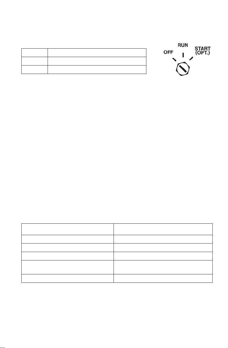
OPERATION
Ignition Switch
The ignition switch has three positions.
OFF Vehicle / IDD power off
RUN Vehicle / IDD power on
START Activates starter motor (if equipped)
If equipped with electric start, turn the key to
START to crank the engine. When the key is
released, it automatically returns to the RUN position.
Snowmobiles equipped with electric start and/or IDD are equipped with
a battery. If the key remains in the RUN position after using the engine
stop switch to stop the engine, the IDD remains active. The IDD screen
will turn off after several minutes of inactivity, but the IDD will
continue to draw a small amount of current from the battery until the
key is turned off. This feature is useful for accessing the IDD without
starting the engine, but turn the key off when the IDD is not in use.
The IDD is not dependent on the battery while the engine is running, but
the battery supplies a constant power source when the engine is turned
off or when the engine is transitioning between forward and reverse
operation. If the battery is not installed, the IDD reboots when the
engine is started and when electronic reverse (PERC) is used.
Emergency Stopping
The following chart lists methods for stopping the snowmobile in the
event of an emergency. See page 81 for more information about the
engine stop switch and throttle release switch.
SYSTEM WHAT IT DOES
Ignition Switch Interrupts ignition circuit
Brake Slows jackshaft
Auxiliary Engine Stop Switch Interrupts ignition circuit
Throttle Release Switch Enables Engine Control Unit (ECU)
software RPM limit
Tether Switch (Option) Interrupts ignition circuit
73
Page 76

OPERATION
Starting the Engine
NOTICE: Engaging the starter when the engine is running WILL result in serious
1. Turn the key to the RUN position.
2. Pull the auxiliary engine stop switch up to the RUN position.
3. If equipped with electric start, turn the key to START to crank the
4. If not equipped with electric start, grasp the starter handle and pull
TIP:Don't pull the starter rope to the fully extended position and don't allow it to
5. If the engine does not start after several attempts, slightly depress
CAUTION! To avoid injury and/or engine damage, do not operate the electric
starter or pull-rope starter while the engine is running.
NOTICE: Operating the vehicle immediately after cold starting could cause
Restarting an Engine
If the rider stops the engine by pushing the engine stop switch down,
restart the engine using the normal starting procedure. If the engine fails
to start using the normal procedure:
1. Push the engine stop switch down to the OFF position.
2. Turn the key to the OFF position.
3. With both switches OFF, squeeze and hold the throttle in the wide
4. Crank the engine several times to draw fresh air through the engine.
5. Release the throttle.
6. Restart the engine using the normal starting procedure.
engine damage, especially if the snowmobile is in reverse. Never
engage the starter when the engine is running.
engine. Release the key to the RUN position when the engine starts.
slowly until the recoil engages; then pull abruptly to crank the
engine.
snap back into the housing. Damage may result.
the throttle (no more than 1/4 inch (6 mm) open) while cranking the
engine. When the engine starts, immediately release the throttle.
engine damage. Allow the engine to warm up for several minutes
before operating the vehicle. If cold drive-away is attempted, the
engine RPM may stumble slightly to protect the engine.
open position.
74
Page 77

OPERATION
Break-In Period
Engine Break-In
Always follow these recommended break-in procedures for new or
rebuilt engines. The first tank of fuel is considered the break-in period
for the engine.
Premix the first tank of fuel and fill the oil reservoir as outlined below.
Oil added to the fuel and oil injection systems will provide the necessary
engine lubrication.
Oil Recommendations
First Tank of Fuel: POLARIS VES 2-Cycle Oil
After Break-in: POLARIS VES 2-Cycle Oil
See page 137 for the part numbers of POLARIS products.
Never mix brands of oil. Serious chemical reactions can cause injection
system blockage, resulting in serious engine damage. Oils may also be
incompatible and the result could be sludge formation, filter blockage,
and reduced cold weather flow rates. All POLARIS oils are compatible
with each other.
Initial Fuel Premix
Always premix fuel in 5-gallon (19-liter) increments in a separate fuel
container. Never add oil directly to the fuel tank.
Fuel VES 2-Cycle Oil Ratio
Each 5 gal. (19 l) 16 oz. (473 ml) 40:1
75
Page 78

OPERATION
Break-In Period
Engine Break-In
Excessive heat build-up during the first three hours of operation will
damage close-fitted engine parts. Do not operate at full throttle or high
speeds for extended periods during the first three hours of use. Vary the
throttle openings and vehicle speeds to reduce friction on all closefitting machined parts, allowing them to break in slowly without
damage.
NOTICE: Use of any lubricants other than those recommended by POLARIS
Drive with extra caution during the break-in period. Perform regular
checks on fluid levels, lines, and all other important areas of the
snowmobile.
Oil Injection System
Always check and fill the oil bottle when refueling. See page 80.
NOTICE: Serious engine damage can occur without the proper lubrication.
Drive Belt Break-In
The break-in period for a new drive belt is 30 miles (48 km). During this
time, vary the throttle position under 50% and limit full throttle use.
may cause serious engine damage. We recommend the use of
POLARIS lubricants for your vehicle.
Check the oil bottle level often during the first tank of fuel. If the oil
level doesn't go down, contact your dealer immediately.
Always take time to warm up the belt and driveline prior to operating
the snowmobile. Free the track and skis from the ground before
engaging throttle.
76
Page 79

OPERATION
Track Warm-Up
WARNING! A loose track or flying debris could cause serious injury or death.
Stand clear of the front of the snowmobile and the moving track. Never hold the
snowmobile up or stand behind it while warming up the track. Do not use
excessive throttle during warm-up or when the track is free-hanging. Use a
stable rear support.
WARNING! Use of traction products such as studs will increase the possibility
of track damage and/or failure. This could cause loss of control, resulting in
serious injury or death. Always inspect for track damage before operating the
snowmobile.
Follow these steps to ensure proper warm-up of the engine, drive train
and track.
1. Never rotate a dry track. For best track performance, always
lubricate the track with water or snow before rotating the track.
2. Use an appropriate stand to securely support the rear of the
snowmobile at the rear bumper. The track should be about 4 inches
(10 cm) off the ground.
3. Start the engine and allow it to warm up two to three minutes.
4. Depress the throttle abruptly and allow the track to rotate several
revolutions.
TIP:It will take longer to warm up the track sufficiently during colder outdoor
temperatures.
5. Release the throttle, apply the brakes, shut off the engine and lower
the snowmobile to the ground.
6. Grasp the skis by their front loops and move them from side to side
to loosen snow and ice.
Slide Rail and Track Cooling
NOTICE: Inadequate cooling and lubrication will lead to overheating of the slide
rail and track, resulting in premature wear and failure. Reduce speeds
and frequently drive into fresh snow to allow adequate cooling and
polishing of the slide rail and track surfaces. Avoid operating on ice,
hard-packed surfaces or roads.
77
Page 80

OPERATION
WARNING
WARNING
Fuel
Gasoline is highly flammable and explosive under certain conditions.
• Always exercise extreme caution whenever handling gasoline.
• Always refuel outdoors or in a well-ventilated area.
• Always turn off the engine before refueling.
• Do not overfill the tank. Do not fill the tank neck.
• Do not smoke or allow open flames or sparks in or near the area where
refueling is performed or where gasoline is stored.
• If gasoline spills on your skin or clothing, immediately wash it off with soap
and water and change clothing.
• Never start the engine or let it run in an enclosed area. Engine exhaust fumes
are poisonous and can cause loss of consciousness or death in a short time.
The engine exhaust from this product contains chemicals known to cause cancer, birth defects or other reproductive harm. Operate this vehicle only outdoors
or in well-ventilated areas.
78
Page 81

OPERATION
Fuel Recommendation
For peak performance, POLARIS recommends the use of 91 octane fuel
or higher. Although 87 octane fuel is usable, some engine performance
will be lost and fuel economy will decrease. Do not use lower than 87
octane fuel. Do not use fuel containing more than 10% ethanol. Never
use E85 fuel in your snowmobile.
NOTICE: Operating with obstructed fuel systems will result in serious engine
Fuel System Deicers
If you use non-ethanol fuel (sometimes labeled “non-oxygenated”),
POLARIS recommends the regular use of isopropyl-based fuel system
deicer. Add one to two ounces per gallon (8-16 ml per liter) of gasoline
to prevent damage resulting from fuel system icing. Never use deicers
or additives containing methanol. POLARIS recommends the use of
Carbon Clean. See page 137 for the part numbers of POLARIS
products.
If you use fuel with up to 10% ethanol (sometimes labeled
“oxygenated”) do not add deicers or additives that contain any form of
alcohol.
damage. Perform maintenance as recommended.
Prolonged exposure to petroleum based products may damage paint.
Always protect painted surfaces when handling fuel.
79
Page 82

OPERATION
ADD Mark
Safe
Range
Oil
Low Oil Level
Always maintain the oil level between the “ADD” mark and the bottle
neck. Do not fill the bottle neck. See page 75 for oil recommendations.
1. Immediately stop the
engine if the low oil
indicator light comes on.
2. Open the left side panel.
See page 94.
3. View the oil level in the
oil bottle.
4. Add oil as needed before
operating.
NOTICE: Operating the
The oil bottle cap is vented to allow proper oil flow . See your POLARIS
dealer for recommended replacement parts.
snowmobile without
adequate engine
lubrication can result
in serious engine
damage. Always
check the oil level
when refueling. Add oil as needed.
80
Page 83

OPERATION
Step 4
Step 3
Auxiliary Engine Stop Switch
Push the auxiliary engine
stop switch down to ground
out the ignition and stop the
engine quickly. Pull the
switch up to the RUN
position to allow restarting.
Throttle Release Switch
The throttle release switch is designed to stop the engine if all pressure
is removed from the throttle lever and the throttle cable or throttle plates
do not return to the normal closed position.
WARNING! Operating the snowmobile with a faulty throttle release switch can
result in serious injury or death in the event of an accident. If the throttle release
switch does not shut off the engine during a throttle system malfunction,
immediately push down the auxiliary engine stop switch. Do not start the engine
again until the malfunction has been corrected by your dealer.
Test the throttle release switch system daily before operation.
1. Sit on the seat.
2. Start the engine and allow
it to idle.
3. Press and hold the lever
pivot as shown.
4. While preventing the lever
from pivoting, slightly
push the throttle lever as
shown. A properly
functioning switch must
shut down the engine.
Stop Switch
81
Page 84

OPERATION
Throttle Lever
WARNING! An improperly functioning throttle lever may cause erratic
snowmobile behavior and loss of control, which could result in serious injury or
death. If the throttle lever does not work properly, DO NOT start the engine.
If the engine stops abruptly when the throttle lever is released:
1. Turn the ignition switch to OFF.
2. Visually inspect the throttle cable and throttle body to determine
what caused the throttle release switch to activate.
3. Test the throttle lever by compressing and releasing it several times.
The lever and cable must return to the idle position quickly and
completely.
4. If the throttle lever operates properly, turn the ignition switch on and
go through normal starting procedures.
5. If the engine doesn’t start, take the snowmobile to an authorized
POLARIS dealer for service.
Throttle Lever Freeplay Inspection
Throttle lever freeplay is the gap created between the throttle lever and
throttle block, as you push the throttle lever, prior to the throttle cable
opening the throttle body plates. Excessive freeplay in the throttle cable
may cause the throttle release switch to activate, potentially stalling the
engine or preventing the engine from starting.
To inspect throttle lever freeplay,
follow these steps:
1. Stop the engine.
2. Slightly push the throttle lever
until you feel the cable tension
increase (throttle plates
opening).
3. Insert the blade of a feeler
gauge between the throttle
lever and throttle block. The
gap must be .009-.029 in.
(0.25-0.76 mm).
4. Adjust freeplay if the gap does not meet specification. See page 83.
Gap
.009-.029 in.
(0.25-0.76 mm)
82
Page 85

OPERATION
Throttle Lever
Throttle Lever Freeplay Adjustment
Adjust throttle lever freeplay using the in-line throttle cable adjuster.
Lock
Nut
1. Locate the in-line adjuster on the throttle cable.
2. Loosen the lock nut.
3. Rotate the adjuster clockwise to DECREASE freeplay. Rotate the
adjuster counter-clockwise to INCREASE freeplay.
4. When freeplay is adjusted to .009-.029 in. (0.25-0.76 mm), tighten
the lock nut against the adjuster.
5. Start the engine and allow it to idle.
6. Turn the handlebar to the full left and full right positions. Verify that
engine RPM does not increase as the handlebar is turned. If engine
RPM increases, the throttle lever freeplay is too tight and must be
readjusted.
WARNING! Do not operate the snowmobile if throttle cable freeplay is to o tight.
In-Line
Adjuster
83
Page 86

OPERATION
WARNING
POLARIS Electronic Reverse Control (PERC)
Improper reverse operation, even at low speeds, may cause loss of control,
resulting in serious injury or death. Damage will occur to the chaincase if shifting
is attempted when the engine is operating above idle speed.
• Shift to or from reverse only when the snowmobile is stopped and when
engine speed is at idle.
• Look behind the vehicle before and while backing.
• Avoid sharp turns.
• Apply throttle slowly.
Electronic reverse will activate only if the engine RPM is below 4000.
NOTICE: Engaging the starter when the engine is running WILL result in serious
engine damage, especially if the snowmobile is in reverse. Never
engage the starter when the engine is running.
84
Page 87

OPERATION
POLARIS Electronic Reverse (PERC)
Engaging Reverse
1. Stop the snowmobile and leave the engine idling.
2. Make sure the area behind your vehicle is clear.
3. Push the yellow reverse button on the left-hand control for one
second, then release. The engine will automatically reduce RPM
and start a reverse rotation. A flashing reverse light on the
instrument panel will indicate that the snowmobile is in reverse.
4. Apply the throttle slowly to make sure the snowmobile is in
reverse.The maximum engine RPM will be 6000 when in reverse.
TIP:If the engine stops running, the snowmobile will be in forward gear when it's
restarted.
Disengaging Reverse
1. Stop the snowmobile and leave the engine idling.
NOTICE: Engaging the starter when the engine is running WILL result in serious
2. Push the yellow reverse button for one second and release. The
3. Apply the throttle slowly to make sure the snowmobile is in
engine damage, especially if the snowmobile is in reverse. Never
engage the starter when the engine is running.
engine will slow and begin to rotate forward. The light on the
instrument panel will shut off.
forward.
85
Page 88

OPERATION
Daily Storage
At the end of each ride, park the snowmobile on a level surface and
support it at the rear with an appropriate track stand. The track should be
suspended approximately 4 inches (10 cm) off the ground.
Remove the key and cover the snowmobile.
Towing
For your safety, do not attempt to use a tow hitch until you've read the
following warnings and understand the proper hitch functions.
WARNING! Objects towed with a rope have no braking power and can easily
collide with the rear of the snowmobile or other objects, resulting in serious
injury or death. DO NOT tow toboggans, sleds, saucers, or any type of vehicle
with a rope. Only a stiff metal pole connecting the towed object and the tow hitch
on the snowmobile should be used. If passengers are to be towed on a
toboggan or sled, make sure the pole is at least four feet (1.2 meters) long to
prevent any possibility of contact between the snowmobile's track and a person
riding in the towed object.
WARNING! Braking distances increase when towing loads. Slow down to
maintain control of the snowmobile.
If the snowmobile becomes inoperable and must be towed, and if it isn't
possible to use a rigid tow bar, attach the tow rope to the ski spindles
(not to the ski loops) to prevent damage to the steering components.
Remove the drive belt before towing, and have someone ride on the
towed snowmobile to operate the brake and steering when necessary.
NOTICE: Towing a disabled snowmobile with the drive belt in place can result in
serious damage to the engine and drive system. Always remove the
drive belt from a disabled snowmobile before towing.
86
Page 89

MAINTENANCE
Emission Control Information
Any qualified repair shop or qualified person may maintain, replace, or
repair the emission control devices or systems on your snowmobile.
Emission Control Label
Your snowmobile is equipped at the time of sale with an emission
control information (ECI) label and a factory-installed emissions
information hangtag. These items are required by U.S. Environmental
Protection Agency regulations. The ECI label is permanently affixed to
either the right side of the tunnel or the engine recoil cover. The ECI
label should not be removed, even after you purchase the snowmobile.
You may remove the factory-installed emissions information hangtag,
which is intended solely for your use in making a purchasing decision.
Emission Control Maintenance Requirements
Your snowmobile is certified to operate on gasoline with a minimum
octane level of 87 (R+M)/2. If your snowmobile is equipped with a
check engine light and it comes on, you must take your snowmobile to a
qualified dealer for diagnostic service. Specifications and adjustments
for engine tune-ups are located in the Service Manual, which is
available to your qualified service technician. Reverse (if equipped)
must not be engaged during engine tune-ups.
Owner's Responsibilities
Please read the Snowmobile Engine Emissions Limited Warranty , and
read the maintenance section of your owner's manual. You are
responsible for ensuring that the specified maintenance is performed.
POLARIS recommends that you contact an authorized POLARIS dealer
to perform any service that may be necessary.
Non-ionizing Radiation
This vehicle emits some electromagnetic energy. People with active or
non-active implantable medical devices (such as heart monitoring or
controlling devices) should review the limitations of their device and the
applicable electromagnetic standards and directives that apply to this
vehicle.
87
Page 90

MAINTENANCE
POLARIS Recommended Maintenance Program
To ensure many trouble-free miles of snowmobiling enjoyment, follow
recommended regular maintenance and perform service checks as
outlined in this manual. Record maintenance and service in the
Maintenance Log beginning on page 171.
The recommended maintenance schedule on your snowmobile calls for
service and maintenance inspections at 150 miles (240 km), 500 miles
(800 km) and 1000 miles (1600 km). These inspections should be
performed by a qualified service technician. For continued optimum
performance and component life, continue maintenance checks at 1000
mile (1600 km) intervals.
All necessary replacement parts and labor incurred, with the exception
of authorized warranty repairs, become the responsibility of the
registered owner. If, during the course of the warranty period, part
failures occur as a result of owner neglect in performing recommended
regular maintenance, the cost of repairs are the responsibility of the
owner.
Personal safety is critical when attempting to service or make
adjustments to your snowmobile. If you're not familiar with safe service
or adjustment procedures and the use of tools, or if you don't feel
comfortable performing these tasks yourself, contact an authorized
POLARIS dealer for service.
NOTICE: Hot components can cause damage to plastic. Always make sure the
exhaust system and engine have cooled before tipping the snowmobile on its side for service or inspection.
88
Page 91

MAINTENANCE
Periodic Maintenance Interval Table
The following chart is a guide based on average riding conditions. You
may need to increase frequency based on riding conditions. When
inspection reveals the need for replacement parts, always use genuine
POLARIS parts, available from your POLARIS dealer.
Item See
Clutch Alignment Offset
(without belt)
Drive Belt Condition 115 IIII
Clutches 114 CCC
Belt Tension -- II II
Clutch Sheaves 114 IIII
Engine Mounts -- IIII
Recoil Rope -- II II
VES System
(600 Engine Only)
Coolant Level 105 IIRI
Coolant Hose -- II II
Coolant Circulation -- II I
Coolant Leaks -- IIII
Spark Plugs 104 IIRI
Exhaust Pipe 108 II
Exhaust Retaining
Springs
I - Inspect (clean, adjust, tighten, lubricate, replace if necessary)
C - Clean R - Replace L - Lubricate
Page
108 IIII
150 mi.
(240 km)
114 III
ENGINE/COOLING
-- C
500 mi.
(800 km)
CLUTCH
Frequency
1000 mi.
(1600 km)
2000 mi.
(3200 km)
Pre-
Season
89
Page 92

MAINTENANCE
Periodic Maintenance Interval Table
Item See
Hose Routing -- IIII
Hose Condition -- II II
Fluid Leaks -- IIII
Brake Pads 110 IIII
Brake Disc -- IIII
Parking Brakes 70 IIII
Brake System 69
Brake Fluid 111 I
Throttle Lever 82 II I II
Fuel Lines 101 IIII
Oil Lines III
Air Box -- III II
Auxiliary Shut-Off
Switch
Throttle Release Switch 81 II I II
Ignition Switch -- III I I
Taillight 72 II I II
Brake Light 72 III I I
Headlight 72 III I I
I - Inspect (clean, adjust, tighten, lubricate, replace if necessary)
C - Clean R - Replace L - Lubricate
Page
150 mi.
(240 km)
110
FUEL MANAGEMENT
ELECTRICAL
72 II I II
(800 km)
BRAKES
500 mi.
Frequency
1000 mi.
(1600 km)
2000 mi.
(3200 km)
Pre-
Season
I
90
Page 93

MAINTENANCE
Periodic Maintenance Interval Table
Item See
Ski Toe Alignment -- III
Suspension Mounting
Bolts
Bolt Torques II I
Steering Fasteners -- III IC
Rear Suspension
Fasteners
Suspension Shock Oil -- R
Rear Shock Threads 98 L
Skags (Wear Bars) 125 III I I
Ski Saddle/Spindle Bolts -- III I I
Drive Chain Tension 109 III II
Hood and Side Panel
Fasteners
Rear Wheel Idler Bolts 121 II I II
Idler Bolt Jam Nut 121 III I I
Handlebar Centering -- I
Tether Switch and Strap 72 III I I
Track Tension 120 II I I I
Track Alignment 122 III I I
Front Limiter Strap -- II I I I
Rail Slide Condition 128 I
Chaincase Oil 98 IRI R I
I - Inspect (clean, adjust, tighten, lubricate, replace if necessary)
C - Clean R - Replace L - Lubricate
Page
150 mi.
(240 km)
-- II I I I
-- II I I I
94 II I II
(800 km)
CHASSIS
500 mi.
Frequency
1000 mi.
(1600 km)
2000 mi.
(3200 km)
Pre-
Season
91
Page 94

MAINTENANCE
Diagnostic Display Code Definitions
Open Load: There is a break in the wires that lead to the item listed in
the chart (injector, fuel pump, etc.), or the item has failed.
Short-to-Ground:
control unit and the item listed in the chart.
The wire is shorted to ground between the electronic
Shorted Load:
The wires leading to the item listed in the chart are
shorted together, or the item has shorted internally.
Short-to-Battery:
The wire leading from the item listed in the chart to
the electronic control unit is shorted to a wire at battery voltage.
Diagnostic Codes
Component Condition SPN FMI
Throttle Position Sensor
Vehicle Speed Sensor Data Erratic, Intermittent or Missing 84 2
Intake Air Temperature Sensor Voltage Too High 105 3
Barometric Pressure Sensor
Engine Temperature Sensor
Alternator Power Supply
Potential (DC Chassis Voltage)
Exhaust Temperature Sensor Voltage Too High 173 3
ECU Memory Checksum/CRC Error 628 13
Injector 1 (MAG Driver Circuit Open/Grounded 651 5
Injector 2 (PTO) Driver Circuit Open/Grounded 652 5
Knock Sensor 1 Voltage Too Low 731 4
Ignition Coil Primary Driver 1
(MAG)
Fuel Pump Driver Circuit Driver Circuit Open/Grounded 1347 5
Voltage Too High 51 3
Voltage Too Low 4
Abnormal Rate of Change 10
Voltage Too Low 4
Voltage Too High 108 3
Voltage Too Low 4
Voltage Too High 110 3
Voltage Too Low 4
Temperature Too High 16
Engine Overheat Shutdown 0
Temperature Above Normal Range 15
Voltage Too High 167 3
Voltage Too Low 4
Voltage Too Low 4
Driver Circuit Short to B+ 3
Driver Circuit Short to B+ 3
Driver Circuit Open/Grounded 1268 5
92
Page 95

MAINTENANCE
Diagnostic Display Code Definitions
Diagnostic Codes
Component Condition SPN FMI
Knock Level Cylinder 1 (MAG) Maximum Detonation Correction
Knock Level Cylinder 2 (PTO) Maximum Detonation Correction
Sensor Supply Voltage 1
(TPS/TMAP Sensor Power)
Sensor Supply Voltage 2
(Ground Speed Sensor)
ECU Output Supply Voltage 2
(Injection Supply PWR)
Throttle Release Signal Voltage Too High 520194 3
Chassis Relay Driver Circuit Open/Grounded 520208 5
Exhaust Valve Solenoid
(600 Only)
EV Actuator Driver (Controller)
(800 H.O. Only)
Electronic Oil Pump Driver Circuit Open / Grounded 3589 4
Oil Pump or Fuel Injector
Settings not Programmed
Limit Reached
Knock Above Critical Level 16
Limit Reached
Knock Above Critical Level 16
Voltage Too Low 3509 4
Voltage Too Low 3510 4
Voltage Too High 3598 3
Voltage Too Low 4
Voltage Too Low 4
Throttle Stuck 7
Driver Circuit Short to B+ 3
Driver Circuit Grounded 520215 5
Driver Circuit Short to B+ 3
Voltage Too High 520324 3
Voltage Too Low 4
Learn Failure 13
Hardware Failure 12
Commanded Pos. Not Achieved 7
PWM Set Missing 2
MAX Temperature Exceeded 520334 31
Signal Out of Range - Valve Open 520325 31
Signal Out of Range - Valve Mid 520326 31
Signal Out of Range - Valve Closed 520327 31
Short to Battery Voltage 520335 3
Short to Ground 4
Abnormal Transition 10
Driver Circuit Grounded 5
Out of Calibration 520241 13
1352 0
1353 0
93
Page 96

MAINTENANCE
Strap
1/4-Turn
Fasteners
Opening
Removing
Hood and Side Panels
The hood and side panels protect the operator from moving parts. Never
operate a snowmobile with the side panels open or removed. Always
ensure that the hood and side panels are installed and securely latched
before starting the engine.
Side Panels (Opening/Removing)
To open a side panel, rotate the
two 1/4-turn fasteners at the
upper edges of the side panel.
Release the strap at the lower
edge of the side panel.
T o remove a side panel, open the
side panel, then pull the panel
outward to release the tabs at the
lower edge of the panel. Lift the
side panel away from the
snowmobile.
94
Page 97

Hood Removal and Installation
1/4-Turn
Fastener
1. Remove the side panels.
2. Rotate the 1/4-turn fasteners
at the upper corners of the
hood.
3. Disconnect the wire harness
leading to the console
electronics.
4. Remove the hood assembly.
5. To reinstall the hood, slide
the nose clips into the
nosepan.
6. Position the hood and align
the 1/4-turn fasteners at the
back of the hood. Secure the
fasteners.
7. Reconnect the wire harness.
8. Reinstall the side panels.
MAINTENANCE
Wire Harness
95
Page 98

MAINTENANCE
L-Wrench
Step 3
Tools
An L-wrench and a tool kit (containing a spare belt, spark plug wrench
and provisions for two spare spark plugs) are provided with the
snowmobile. Open the left side panel to access the tools.
The L-wrench is used to open
and close the driven clutch
when working with the drive
belt. The L-wrench, when
properly engaged in the bracket,
secures the fender to the
console. To retrieve the Lwrench, rotate it counterclockwise and slide it upward
from the bracket. When it’s not
in use, return the L-wrench to
the bracket and rotate it clockwise.
The tool kit is stored in a
container attached to the left
tube of the front bumper. Use
the following procedure to
remove the spare belt container
from the snowmobile.
1. Rotate the spark plug
wrench counter-clockwise
to release it from the
bracket.
2. Pull the wrench upward to
remove it.
NOTE: The wrench secures the
container to the bumper.
3. Tilt the tool kit container
until the bracket detaches
from the bumper tube.
Spark Plug Wrench
96
Page 99

MAINTENANCE
Front Rear
Step 5
Step 6
Tools
4. Pull the container out of the compartment.
5. When reinstalling the drive belt into the container, fold the belt as
shown. Verify that the belt loop at the rear of the container is
positioned slightly higher than the front loop.
Step 4
6. Slide the container into the
engine compartment at an
angle.
7. Position the container
bracket onto the bumper
tube and rotate it downward.
8. Reinstall the spark plug
wrench into the bracket and
through the hole in the
bumper tube.
9. Rotate the spark plug
wrench clockwise until it
locks into place.
97
Page 100
MAINTENANCE
Rear Shock Body
Lubricate rear shock body threads
seasonally with a low-temperature
synthetic grease.
Driveshaft Bearing
This model has sealed bearings that
require no additional lubrication.
Chaincase Oil
Check and change the chaincase oil at the intervals outlined in the
Periodic Maintenance Table beginning on page 88. Maintain the oil
level at the top of the fill plug hole. POLARIS recommends the use of
Synthetic Chaincase Lubricant. See page 137 for the part numbers of
POLARIS products.
Oil Level Check
1. Position the snowmobile on
a level surface.
2. Remove the fill plug.
3. Using a funnel, slowly add
the recommended oil until
the fluid begins to overflow.
4. Clean the area with a clean,
dry shop towel.
5. Reinstall the fill plug.
Torque: 6-10 ft-lbs (8-13 Nm)
Fill Plug
Threads
98
 Loading...