

Page 1

2012 RANGER RZR 570 / INTL
SERVICE MANUAL
FOREWORD
The information printed within this publication includes the latest product information at time of print. The most recent
version of this Service Manual is available in electronic format at
www.polarisdealers.com.
This Service Manual is designed primarily for use by
equipped shop and should be kept available for reference. All references to left and right side of the vehicle are from
the operator's perspective when seated in a normal riding position.
Some pro cedures ou tlined i n th is man ual re quire a sou nd kn owledge of me chanical t heory, to ol use, and sho p
proc
edures in order to perform the work safely and correctly. Technicians should read the text and be familiar with the
service procedures before starting any repair. Certain procedures require the use of special tools. Use only the proper
tools as specified. If you ha ve any doubt as to yo ur ability to perform any of th e procedures outlined in th is Service
Manual, contact an authorized dealer for service.
We value your input and appreciate any assistance you can provide in helping make these publications more useful.
Plea
se provide any feedback you may have regarding this manual. Authorized dealers can submit feedback using 'Ask
Polaris'. Click on 'Ask Polaris', and then click on 'Publications Question'.
Consumers, please provide your feedback in writing to: Polaris Indu
2100 Hwy 55, Medina, MN 55340.
Publication Printed November 2011 (PN 9923523) Rev. 3
© Copyright 2011 Polaris Sales Inc. All information contained within this publication is based on the latest product information at the time of publication. Due to constant
improvements in the design and quality of production components, some minor discrepancies may result between the actual vehicle and the information presented in this
publication. Dep ictions an d/or p rocedures in t his pu blication are int ended for re ference use only. N o liability can be accept ed for omissions or inaccura cies. Any
reprinting or reuse of the depictions and/or procedures contained within, whether whole or in part, is expressly prohibited. Printed in U.S.A.
certified Polaris Master Service Dealer technicians in a p roperly
stries Inc. ATTN: Service Publications Department,
Page 2

UNDERSTANDING MANUAL SAFETY LABELS AND DIRECTIONS
WARNING
CAUTION
CAUTION
Throughout this manual, important information is brought to your attention by the following symbols:
SAFETY ALER T WARNING ind icates a po tential h azard that ma
bystander or person(s) inspecting or servicing the vehicle.
SAFETY ALER T CAUTION indicates a potential h
vehicle.
CAUTION indicates special p
NOTE provides key information by clarifying
IMPORTANT provides key reminders during disassembly
recautions that must be taken to avoid vehicle damage or property damage.
instructions.
azard tha t may r esult in min or personal in jury or damage to th e
NOTE:
IMPORTANT:
, assembly and inspection of components.
y result in se vere injury or dea th to the o perator,
TRADEMARKS
POLARIS ACKNOWLEDGES THE FOLLOWING PRODUCTS MENTIONED IN THIS MANUAL:
Loctite, Registered Trademark of the Loctite Corporation
Nyogel, Trademark of Wm. F. Nye Co.
Fluke, Registered Trademark of John Fluke Mfg. Co.
Mity-Vac, Registered Trademark of
Torx, Registered Trademark of Textron
Hilliard, Trademark of the H
Warn, Trademark of Warn Industries
FOX, Registered Trademark of FOX RACING SHOX
RydeFX, Registered Trademark of ArvinMeritor
Some Pola ris factor y pu blications can be do wnload
www.purepolaris.com or by contacting the nearest Polaris dealer.
illiard Corporation
Neward Enterprises, Inc.
ed fro m www.polarisindustries.com, pu rchased fr om
Page 3

1
GENERAL INFORMATION
2
MAINTENANCE
3
ENGINE / COOLING SYSTEM
4
ELECTRONIC FUEL INJECTION
5
BODY / STEERING / SUSPENSION
6
CLUTCHING
7
FINAL DRIVE
8
TRANSMISSION
BRAKES
9
ELECTRICAL
10
Page 4

Page 5

GENERAL INFORMATION
CHAPTER 1
GENERAL INFORMATION
MODEL INFORMATION . . . . . . . . . . . . . . . . . . . . . . . . . . . . . . . . . . . . . . . . . . . . . . . . . . 1.2
MODEL IDENTIFICATION . . . . . . . . . . . . . . . . . . . . . . . . . . . . . . . . . . . . . . . . . . . . . . . . 1.2
ENGINE DESIGNATION NUMBER . . . . . . . . . . . . . . . . . . . . . . . . . . . . . . . . . . . . . . . . . 1.2
VIN IDENTIFICATION . . . . . . . . . . . . . . . . . . . . . . . . . . . . . . . . . . . . . . . . . . . . . . . . . . . 1.2
VEHICLE AND ENGINE SERIAL NUMBER LOCATION . . . .
VEHICLE INFORMATION . . . . . . . . . . . . . . . . . . . . . . . . . . . . . . . . . . . . . . . . . . . . . . . . . 1.3
PUBLICATION NUMBERS. . . . . . . . . . . . . . . . . . . . . . . . . . . . . . . . . . . . . . . . . . . . . . . . 1.3
REPLACEMENT KEYS . . . . . . . . . . . . . . . . . . . . . . . . . . . . . . . . . . . . . . . . . . . . . . . . . . 1.3
SPECIAL TOOLS . . . . . . . . . . . . . . . . . . . . . . . . . . . . . . . . . . . . . . . . . . . . . . . . . . . . . . . 1.3
GENERAL SPECIFICATIONS. . . . . . . . . . . . . . . . . . . . . . . . . . . . . . . . . . . . . . . . . . . . . . 1.4
2012 RANGER RZR 570 . . . . . . . . . . . . . . . . . . . . . . . . . . . . . . . . . . . . . . . . . . . . . . . . . 1.4
2012 RANGER RZR 570 . . . . . . . . . . . . . . . . . . . . . . . . . . . . . . . . . . . . . . . . . . . . . . . . . 1.5
2012 RANGER RZR 570 INTL . . . . . . . . . . . . . . . . . . . . . . . . . . . . . . . . . . . . . . . . . . . . . 1.6
2012 RANGER RZR 570 INTL . . . . . . . . . . . . . . . . . . . . . . . . . . . . . . . . . . . . . . . . . . . . . 1.7
MISC. SPECIFICATIONS AND CHARTS . . . . . . . . . . . . . . . . . . . . . . . . . . . . . . . . . . . . . 1.8
CONVERSION TABLE . . . . . . . . . . . . . . . . . . . . . . . . . . . . . . . . . . . . . . . . . . . . . . . . . . . 1.8
STANDARD BOLT TORQUE SPECIFICATION. . . . . . . . . . . . . . . . . . . . . . . . . . . . . . . . 1.9
METRIC BOLT TORQUE SPECIFICATION. . . . . . . . . . . . . . . . . . . . . . . . . . . . . . . . . . . 1.9
SAE TAP / DRILL SIZES . . . . . . . . . . . . . . . . . . . . . . . . . . . . . . . . . . . . . . . . . . . . . . . . 1.10
METRIC TAP / DRILL SIZES . . . . . . . . . . . . . . . . . . . . . . . . . . . . . . . . . . . . . . . . . . . . . 1.10
DECIMAL EQUIVALENTS . . . . . . . . . . . . . . . . . . . . . . . . . . . . . . . . . . . . . . . . . . . . . . . 1.10
. . . . . . . . . . . . . . . . . . . . . 1.2
1
1.1
9923523 - 2012 RANGER RZR 570 Service Manual
© Copyright 2011 Polaris Sales Inc.
Page 6

GENERAL INFORMATION
}
Machine Model Number Identification
}
}
Model Year
Designation
Basic Chassis
Designation
Engine Designation
Emissions &
Model Option
R 1 2 V H 5 7 A D
}
4 X A V H 5 7 A * B P 0 0 0 0 0 0
}
1 2 3 4 5 6 7 8 9 10 11 12 13 14 15 16 17
World
Mfg. ID
Engine
Vehicle Description
Vehicle Identifier
Check Digit
Model
Year
Body Style
Plant No.
Individual Serial No.
* This could be either
a number or a letter
Powertrain
Emissions
Figure 1-1
Engine Serial
Figure 1-2
Number
MODEL INFORMATION
Model Identification
The machine model number must be used with any correspondence regarding warranty or service.
Engine Designation Number
1204286..............................................................................Single Cylinder, Liquid Cooled, OHV 4 Stroke, Electric Start
VIN Identification
Vehicle and Engine Serial Number Lo
Whenever corresponding about a Polaris ORV, refer to the ve hicle identification number (VIN) and the engine serial
number.
The VIN can be found stamped on a portion of the left-han
(see Figure 1-1)
The engine model and serial number can be found on a decal applied to the crankcase on the front of the engine.
(see Figure 1-2)
1.2
cation
d rear upper frame rail, above the left rear wheel.
9923523 - 2012 RANGER RZR 570 Service Manual
© Copyright 2011 Polaris Sales Inc.
Page 7

VEHICLE INFORMATION
Key Series
Number
KEY COVER
P/N 5533534
Publication Numbers
Model Model No. Owner’s Manual Parts Manual
GENERAL INFORMATION
1
2012 RANGER RZR
2012 RANGER RZR 570 INTL. R12VH57FX 9923521 9924058
NOTE: When ordering service parts be sure to use the correct parts manual.
NOTE: Polaris fa ctory pu blications c an be fo und a
www.purepolaris.com.
570 R12VH57AD 9923521 9923522
t www.pola risindustries.com or p urchased f rom
Replacement Keys
Replacement keys can be made from the original key. To identify which series the key is, take the first two digits on the
original key and refer to the chart to the right for the proper part number.
Series# Part Number
20 4010278
21 4010278
22 4010321
23 4010321
27 4010321
28 4010321
31 4110141
32 4110148
67 4010278
68 4010278
SPECIAL TOOLS
Special tools may be required while servicing this vehicle. Some of the tools listed or depicted are mandatory, while other
tools maybe substituted with a similar to ol, if ava ilable. Polaris r ecommends the use of Polaris Special Tools when
servicing any Polaris product. Dealers may order special tools through Polaris’ official tool supplier, SPX Corporation,
by phone at 1-800-328-6657 or on-line at
http://polaris.spx.com/.
1.3
9923523 - 2012 RANGER RZR 570 Service Manual
© Copyright 2011 Polaris Sales Inc.
Page 8

GENERAL INFORMATION
GENERAL SPECIFICATIONS
MODEL: 2012 RANGER RZR 570
MODEL NUMBER: R12VH57AD
ENGINE NUMBER: 1204286
Category Dimension / Capacity
Length 107.5 in. / 273.05 cm
Width 50 in. / 127 cm
Height 69 in. / 175.26 cm
Wheel Base 77 in. / 196 cm
Ground Clearance 10 in. / 25.4 cm
Dry Weight 970 lbs. / 440 kg
Front Storage
Capacity
Cargo Box Dimension
(LxWxH)
Cargo Box Capacity 300 lbs. / 136 kg
Maximum Weight
Ca
pacity (Payload)
Hitch Towing Capacity 1500 lbs. / 680 kg
Hitch Tongue Capacity 150 lbs. / 68 kg
20 x 40 x 9" (51 x 102 x 23 cm)
(Inclu
25 lbs. / 11.3 kg
740 lbs. / 335.6 kg
des rider(s), cargo, accessories
and trailer tongue weight)
1.4
9923523 - 2012 RANGER RZR 570 Service Manual
© Copyright 2011 Polaris Sales Inc.
Page 9

GENERAL INFORMATION
MODEL: 2012 RANGER RZR 570
MODEL NUMBER: R12VH57AD
ENGINE NUMBER: 1204286
Engine
Platform
Engine Number 1204286
Engine Displacement 567cc
Number of Cylinders 1
Bore & Stroke (mm) 99 x 73.6 mm
Compression Ratio 10:1
Compression Pressure 80 - 120 psi (decompression)
Engine Idle Speed 1200 ± 100 RPM
Engine Max Operating RPM 7750 RPM
Lubrication Pressurized Wet Sump
Oil Requirements PS-4 Plus Synthetic
Oil Capacity 2 qts. / 1.9 liters
Coolant Capacity 4.25 qts. (4 l)
Overheat Warning Instrument Cluster Indicator
Exhaust System
Fuel System Type Bosch M17 EFI
Fuel Delivery Electronic Fuel Pump (in tank)
Fuel Pressure 43-48 psi (296.5 - 331 KPA)
Fuel Filters In tank, See Chapter 4
Fuel Capacity / Requirement
Alternator Max Output 650 Watts @ 7000 RPM
Headlights 2 - Halogen: Single Beam 55W
Tail / Brake 2 - 6 Watts / 2 - 27 Watts
Starting System Electric Start
Ignition System Bosch M17 (ECU Controlled)
Ignition Timing (Variable) ECU Controlled
Spark plug / Gap
Battery (RZR)
Instrument Type Multifunction Instrument Cluster
DC Outlet Standard 12 Volt
Relays
Circuit Breaker Fan Motor: 20 Amp
Fuses (Fuse/Relay Box)
Fuses (Power Fuse Holder)
Domestic Single Cylinder, Liquid
oled, 4-Stroke, DOHC
Co
Single Headpipe / Single Silencer
Fuel System
7.25 gal. (27.4 liters)
87 Octane (minimum)
Electrical
RG4YCX / .0276” - .0315”
.7 - .8 mm)
(
Yuasa YB14-B2 /
14 Amp
EFI / Chassis / Fan / Fuel Pump /
Drive / Fuel Pump: 10 Amp
ghts / EFI / Accessory: 20 Amp
Li
Hr. / 12 Volt
Hea
EFI: 30 Amp
sis: 30 Amp
Chas
dlight
Drivetrain
Transmission Type Polaris Automatic PVT
Drive Ratio - Front 3.818:1
Drive Ratio - Final 3.70:1
Shift Type In Line Shift - H / L / N / R / P
Front Gearcase
Fluid Type / Capacity
Transmission: Main Gearcase
Fluid Type / Capacity
Belt 3211143
Steering / Suspension
Front Suspension
Front Travel 9 in. / 23 cm
Rear Suspension
Rear Travel 9.5 in. / 24 cm
Shock Preload Adjustment
Front / Rear
Toe Out
Wheels / Brakes
Front Wheel Size
Front Tire Type / Size
Rear Wheel Size
Rear Tire Type / Size
Tire Pressure
Brake - Front / Rear
Brake Fluid DOT 4
Polaris Demand Drive Plus
6.75 oz. (200 ml)
Polaris AGL Plus
44 oz. (1300 ml)
Independent Dual A-arm
w/Anti-Sway Bar
Independent Dual A-arm
w/Anti-Sway Bar
Cam Adjustment
Cam Adjustment
1/8 - 1/4 in. (3 - 6.4 mm)
12 x 6 / Steel
Ancla / 25 x 8 R12
12 x 8 / Steel
Ancla / 25 x 10 R12
Front: 10 psi (69 kPa)
Rear: 12 psi (83 kPa)
Foot Actuated - 4 Wheel
Hydraulic Disc
CLUTCH CHART
Shift
ight
We
25-52
(5
632409)
25-48
(5632408)
Meters
(Feet
Altitude
)
0-1500
(0-5000)
1500-3700
(50
00 - 12000)
1
Drive
Spring
Black
(7043594)
Black
(7043594)
1.5
9923523 - 2012 RANGER RZR 570 Service Manual
© Copyright 2011 Polaris Sales Inc.
Page 10

GENERAL INFORMATION
MODEL: 2012 RANGER RZR 570 INTL
MODEL NUMBER: R12VH57FX
ENGINE NUMBER: 1204286
Category Dimension / Capacity
Length 107.5 in. / 273.05 cm
Width 50 in. / 127 cm
Height 69 in. / 175.26 cm
Wheel Base 77 in. / 196 cm
Ground Clearance 10 in. / 25.4 cm
Dry Weight 1001 lbs. / 454 kg
Front Storage
Ca
pacity
Cargo Box Dimension
(LxWxH)
Cargo Box Capacity 300 lbs. / 136 kg
Maximum Weight
pacity (Payload)
Ca
Hitch Towing Capacity 1500 lbs. / 680 kg
Hitch Tongue Capacity 150 lbs. / 68 kg
20 x 40 x 9" (51 x 102 x 23 cm)
ncludes rider(s), cargo, accessories
(I
25 lbs. / 11.3 kg
740 lbs. / 335.6 kg
and trailer tongue weight)
1.6
9923523 - 2012 RANGER RZR 570 Service Manual
© Copyright 2011 Polaris Sales Inc.
Page 11

GENERAL INFORMATION
MODEL: 2012 RANGER RZR 570 INTL
MODEL NUMBER: R12VH57FX
ENGINE NUMBER: 1204286
Engine
Platform
Engine Number 1204286
Engine Displacement 567cc
Number of Cylinders 1
Bore & Stroke (mm) 99 x 73.6 mm
Compression Ratio 10:1
Compression Pressure 80 - 120 psi (decompression)
Engine Idle Speed 1200 ± 100 RPM
Engine Max Operating RPM 7750 RPM
Lubrication Pressurized Wet Sump
Oil Requirements PS-4 Plus Synthetic
Oil Capacity 2 qts. / 1.9 liters
Coolant Capacity 4.25 qts. (4 l)
Overheat Warning Instrument Cluster Indicator
Exhaust System
Fuel System Type Bosch M17 EFI
Fuel Delivery Electronic Fuel Pump (in tank)
Fuel Pressure 43-48 psi (296.5 - 331 KPA)
Fuel Filters In tank, See Chapter 4
Fuel Capacity / Requirement
Alternator Max Output 650 Watts @ 7000 RPM
Headlights (INTL) 2 - Halogen: 55W Low / 60W High
Tail / Brake 2 - 6 Watts / 2 - 27 Watts
INTL Features
Starting System Electric Start
Ignition System Bosch M17 (ECU Controlled)
Ignition Timing (Variable) ECU Controlled
Spark plug / Gap
Battery (RZR)
Instrument Type Multifunction Instrument Cluster
DC Outlet Standard 12 Volt
Relays
Circuit Breaker Fan Motor: 20 Amp
Fuses (Fuse/Relay Box)
Fuses (Power Fuse Holder)
Domestic Single Cylinder, Liquid
oled, 4-Stroke, DOHC
Co
Single Headpipe / Single Silencer
Fuel System
7.25 gal. (27.4 liters)
87 Octane (minimum)
Electrical
Turn Signals, Rear Diff. Control,
rn, Lic. Plate Light
Ho
RG4YCX / .0276” - .0315”
.7 - .8 mm)
(
Yuasa YB14-B2 /
14 Amp
EFI / Chassis / Fan / Fuel Pump /
Drive / Fuel Pump: 10 Amp
ghts / EFI / Accessory: 20 Amp
Li
Hr. / 12 Volt
Hea
EFI: 30 Amp
sis: 30 Amp
Chas
dlight
Drivetrain
Transmission Type Polaris Automatic PVT
Drive Ratio - Front 3.818:1
Drive Ratio - Final 3.70:1
Shift Type In Line Shift - H / L / N / R / P
Front Gearcase
Fluid Type / Capacity
Transmission: Main Gearcase
Fluid Type / Capacity
Belt 3211143
Steering / Suspension
Front Suspension
Front Travel 9 in. / 23 cm
Rear Suspension
Rear Travel 9.5 in. / 24 cm
Shock Preload Adjustment
Front / Rear
Toe Out
Wheels / Brakes
Front Wheel Size
Front Tire Type / Size
Rear Wheel Size
Rear Tire Type / Size
Tire Pressure
Brake - Front / Rear
Brake Fluid DOT 4
Parking Brake Equipped
Polaris Demand Drive Plus
6.75 oz. (200 ml)
Polaris AGL Plus
44 oz. (1300 ml)
570 INTL: 41 oz. (1200 ml)
Independent Dual A-arm
w/Anti-Sway Bar
Independent Dual A-arm
w/Anti-Sway Bar
Cam Adjustment
Cam Adjustment
1/8 - 1/4 in. (3 - 6.4 mm)
12 x 6 Aluminum
Ancla / 25 x 8 R12
12 x 8 Aluminum
Ancla / 25 x 10 R12
Front: 10 psi (69 kPa)
Rear: 12 psi (83 kPa)
Foot Actuated - 4 Wheel
Hydraulic Disc
CLUTCH CHART
Shift
ight
We
25-52
(5
632409)
25-48
(5632408)
Meters
(Feet
Altitude
)
0-1500
(0-5000)
1500-3700
(50
00 - 12000)
1
Drive
Spring
Black
(7043594)
Black
(7043594)
1.7
9923523 - 2012 RANGER RZR 570 Service Manual
© Copyright 2011 Polaris Sales Inc.
Page 12

GENERAL INFORMATION
MISC. SPECIFICATIONS AND CHARTS
Conversion Table
°C to °F:
9/5
1.8
(°C + 32) = °F °F to °C:
9923523 - 2012 RANGER RZR 570 Service Manual
© Copyright 2011 Polaris Sales Inc.
5/9
(°F - 32) = °C
Page 13

Standard Bolt Torque Specification
Grade 2
Grade 5
Grade 8
GENERAL INFORMATION
1
Bolt Size
1/4-20 5 (7) 8 (11) 12 (16)
1/4-28 6 (8) 10 (14) 14 (19)
5/16-18 11 ( 1 5 ) 17 (23) 25 (35)
5/16-24 12 (16) 19 (26) 29 (40)
3/8-16 20 (27) 30 (40) 45 (62)
3/8-24 23 (32) 35 (48) 50 (69)
7/16-14 30 (40) 50 (69) 70 (97)
7/16-20 35 (48) 55 (76) 80 (110)
1/2-13 50 (69) 75 (104) 110 (152)
1/2-20 55 (76) 90 (124) 120 (166)
Grade 2
. Lbs. (Nm)
Ft
Grade 5
Ft. Lbs. (Nm)
Grade 8
Ft. Lbs. (Nm)
Metric Bolt Torque Specification
Grade
Bolt Size
M3 .3 (.5) .5 (.7) 1 (1.3) 1.5 (2) 1.5 (2)
M4 .8 (1.1) 1 (1.5) 2 (3) 3 (4.5) 4 (5)
M5 1.5 (2.5) 2 (3) 4.5 (6) 6.5 (9) 7.5 (10)
M6 3 (4) 4 (5.5) 7.5 (10) 11 (15) 13 (18)
M8 7 (9.5) 10 (13) 18 (25) 26 (35) 33 (45)
M10 14 (19) 18 (25) 37 (50) 55 (75) 63 (85)
M12 26 (35) 33 (45) 63 (85) 97 (130) 11 ( 1 5 0 )
M14 37 (50) 55 (75) 103 (140) 151 (205) 177 (240)
M16 59 (80) 85 (115) 159 (215) 232 (315) 273 (370)
M18 81 (110) 118 (160) 225 (305) 321 (435) 376 (510)
4.6 4.8 8.8 / 8.9 10.9 12.9
Ft. Lbs. (Nm) Dry Threads
9923523 - 2012 RANGER RZR 570 Service Manual
© Copyright 2011 Polaris Sales Inc.
1.9
Page 14
GENERAL INFORMATION
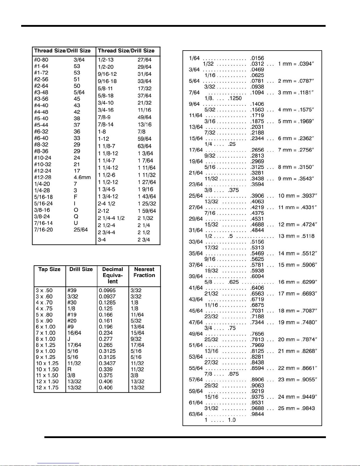
SAE Tap / Drill Sizes
Decimal Equivalents
Metric Tap / Drill Sizes
1.10
9923523 - 2012 RANGER RZR 570 Service Manual
© Copyright 2011 Polaris Sales Inc.
Page 15

MAINTENANCE
CHAPTER 2
MAINTENANCE
SPECIAL TOOLS . . . . . . . . . . . . . . . . . . . . . . . . . . . . . . . . . . . . . . . . . . . . . . . . . . . . . . . 2.2
PERIODIC MAINTENANCE CHART. . . . . . . . . . . . . . . . . . . . . . . . . . . . . . . . . . . . . . . . . 2.3
PERIODIC MAINTENANCE OVERVIEW. . . . . . . . . . . . . . . . . . . . . . . . . . . . . . . . . . . . . 2.3
BREAK-IN PERIOD . . . . . . . . . . . . . . . . . . . . . . . . . . . . . . . . . . . . . . . . . . . . . . . . . . . . . 2.3
MAINTENANCE CHART KEY . . . . . . . . . . . . . . . . . . . . . . . . . . . . . . . . . . . . . . . . . . . . . 2.3
PRE-RIDE - 25 HOUR MAINTENANCE INTERVAL . . . . . . . . . . . . . . . . . . . . . . . . . . . . 2.4
50 - 500 HOUR MAINTENANCE INTERVAL . . . . . . . . . . . . . . . . . . . . . . . . . . . . . . . . . . 2.5
MAINTENANCE QUICK REFERENCE . . . . . . . . . . . . . . . . . . . . . . . . . . . . . . . . . . . . . . 2.6
MAINTENANCE QUICK REFERENCE . . . . . . . . . . . . . . . . . . . . . . . . . . . . . . . . . . . . . . 2.7
GREASE LUBRICATION POINTS . . . . . . . . . . . . . . . . . . . . . . . . . . . . . . . . . . . . . . . . . . 2.8
LUBRICANTS / SERVICE PRODUCTS . . . . . . . . . . . . . . . . . . . . . . . . . . . . . . . . . . . . . . 2.9
GENERAL VEHICLE INSPECTION AND MAINTENANCE. . . . . . . . . . . . . . . . . . . . . . . 2.10
PRE-RIDE / DAILY INSPECTION . . . . . . . . . . . . . . . . . . . . . . . . . . . . . . . . . . . . . . . . . 2.10
FRAME, NUTS, BOLTS, AND FASTENERS . . . . . . . . . . . . . . . . . . . . . . . . . . . . . . . . . 2.10
SHIFT CABLE INSPECTION / ADJUSTMENT. . . . . . . . . . . . . . . . . . . . . . . . . . . . . . . . 2.10
FUEL SYSTEM AND AIR INTAKE . . . . . . . . . . . . . . . . . . . . . . . . . . . . . . . . . . . . . . . . . 2.11
FUEL SYSTEM. . . . . . . . . . . . . . . . . . . . . . . . . . . . . . . . . . . . . . . . . . . . . . . . . . . . . . . . 2.11
FUEL LINE . . . . . . . . . . . . . . . . . . . . . . . . . . . . . . . . . . . . . . . . . . . . . . . . . . . . . . . . . . . 2.11
FUEL PUMP / FUEL FILTERS . . . . . . .
VENT LINES. . . . . . . . . . . . . . . . . . . . . . . . . . . . . . . . . . . . . . . . . . . . . . . . . . . . . . . . . . 2.12
THROTTLE PEDAL INSPECTION . . . . . . . . . . . . . . . . . . . . . . . . . . . . . . . . . . . . . . . . . 2.12
THROTTLE FREEPLAY ADJUSTMENT . . . . . . . . . . . . . . . . . . . . . . . . . . . . . . . . . . . . 2.13
ENGINE AND PVT INTAKE PRE-FILTER SERVICE. . . . . . . . . . . . . . . . . . . . . . . . . . . 2.13
AIR FILTER SERVICE . . . . . . . . . . . . . . . . . . . . . . . . . . . . . . . . . . . . . . . . . . . . . . . . . . 2.14
ENGINE . . . . . . . . . . . . . . . . . . . . . . . . . . . . . . . . . . . . . . . . . . . . . . . . . . . . . . . . . . . . . . 2.16
ENGINE OIL LEVEL . . . . . . . . . . . . . . . . . . . . . . . . . . . . . . . . . . . . . . . . . . . . . . . . . . . . 2.16
ENGINE OIL AND FILTER SERVICE. . . . . . . . . . . . . . . . . . . . . . . . . . . . . . . . . . . . . . . 2.16
ENGINE BREATHER HOSE INSPECTION . . . . . . . . . . . . . . . . . . . . . . . . . . . . . . . . . . 2.18
ENGINE AND TRANSMISSION MOUNTS. . . . . . . . . . . .
COMPRESSION TEST SPECIFICATION . . . . . . . . . . . . . . . . . . . . . . . . . . . . . . . . . . . 2.18
VALVE CLEARANCE INSPECTION . . . . . . . . . . . . . . . . . . . . . . . . . . . . . . . . . . . . . . . 2.18
EXHAUST - SPARK ARRESTOR. . . . . . . . . . . . . . . . . . . . . . . . . . . . . . . . . . . . . . . . . . 2.20
TRANSMISSION AND FRONT GEARCASE. . . . . . . . . . . . . . . . . . . . . . . . . . . . . . . . . . 2.21
SPECIFICATION CHART. . . . . . . . . . . . . . . . . . . . . . . . . . . . . . . . . . . . . . . . . . . . . . . . 2.21
TRANSMISSION LUBRICATION . . . . . . . . . . . . . . . . . . . . . . . . . . . . . . . . . . . . . . . . . . 2.21
FRONT GEARCASE LUBRICATION . . . . . . . . . . . . . . .
COOLING SYSTEM. . . . . . . . . . . . . . . . . . . . . . . . . . . . . . . . . . . . . . . . . . . . . . . . . . . . . 2.25
COOLING SYSTEM EXPLODED VIEW. . . . . . . . . . . . . . . . . . . . . . . . . . . . . . . . . . . . . 2.25
COOLING SYSTEM OVERVIEW . . . . . . . . . . . . . . . . . . . . . . . . . . . . . . . . . . . . . . . . . . 2.26
COOLANT LEVEL INSPECTION . . . . . . . . . . . . . . . . . . . . . . . . . . . . . . . . . . . . . . . . . . 2.26
COOLING SYSTEM PRESSURE TEST. . . . . . . . . . . . . . . . . . . . . . . . . . . . . . . . . . . . . 2.26
COOLANT STRENGTH / TYPE . . . . . . . . . . . . . . . . . . .
COOLING SYSTEM . . . . . . . . . . . . . . . . . . . . . . . . . . . . . . . . . . . . . . . . . . . . . . . . . . . . 2.27
COOLANT DRAIN / FILL . . . . . . . . . . . . . . . . . . . . .
FINAL DRIVE / WHEEL AND TIRE . . . . . . . . . . . . . . . . . . . . . . . . . . . . . . . . . . . . . . . . . 2.28
WHEEL AND HUB TORQUE TABLE . . . . . . . . . . . . . . . . . . . . . . . . . . . . . . . . . . . . . . . 2.28
WHEEL REMOVAL. . . . . . . . . . . . . . . . . . . . . . . . . . . . . . . . . . . . . . . . . . . . . . . . . . . . . 2.28
WHEEL INSTALLATION. . . . . . . . . . . . . . . . . . . . . . . . . . . . . . . . . . . . . . . . . . . . . . . . . 2.29
TIRE INSPECTION. . . . . . . . . . . . . . . . . . . . . . . . . . . . . . . . . . . . . . . . . . . . . . . . . . . . . 2.29
TIRE PRESSURE. . . . . . . . . . . . . . . . . . . . . . . . . . . . . . . . . . . . . . . . . . . . . . . . . . . . . . 2.30
DRIVE SHAFT BOOT INSPECTION . . . . . . . . . . . . . . . . . . . . . . . . . . . . . . . . . . . . . . . 2.30
. . . . . . . . . . . . . . . . . . . . . . . . . . . . . . . . . . . . . 2.12
. . . . . . . . . . . . . . . . . . . . . . . 2.18
. . . . . . . . . . . . . . . . . . . . . . . . 2.23
. . . . . . . . . . . . . . . . . . . . . . . . 2.27
. . . . . . . . . . . . . . . . . . . . . . . . . . . 2.27
2
2.1
9923523 - RANGER RZR 570 Service Manual
© Copyright 2011 Polaris Sales Inc.
Page 16

MAINTENANCE
ELECTRICAL AND IGNITION SYSTEM . . . . . . . . . . . . . . . . . . . . . . . . . . . . . . . . . . . . . 2.30
BATTERY MAINTENANCE . . . . . . . . . . . . . . . . . . . . . . . . . . . . . . . . . . . . . . . . . . . . . . 2.30
BATTERY REMOVAL. . . . . . . . . . . . . . . . . . . . . . . . . . . . . . . . . . . . . . . . . . . . . . . . . . . 2.31
BATTERY INSTALLATION. . . . . . . . . . . . . . . . . . . . . . . . . . . . . . . . . . . . . . . . . . . . . . . 2.31
BATTERY OFF SEASON STORAGE . . . . . . . . . . . . . . . . . . . . . . . . . . . . . . . . . . . . . . 2.31
SPARK PLUG SERVICE . . . . . . . . . . . . . . . . . . . . . . . . . . . . . . . . . . . . . . . . . . . . . . . . 2.32
ENGINE TO FRAME GROUND . . . . . . . . . . . . . . . . . . . . . . . . . . . . . . . . . . . . . . . . . . . 2.33
STEERING . . . . . . . . . . . . . . . . . . . . . . . . . . . . . . . . . . . . . . . . . . . . . . . . . . . . . . . . . . . 2.33
STEERING INSPECTION . . . . . . . . . . . . . . . . . . . . . . . . . . . . . . . . . . . . . . . . . . . . . . . 2.33
STEERING WHEEL FREEPLAY . . . . . . . . . . . . . . . . . . . . . . . . . . . . . . . . . . . . . . . . . . 2.34
TIE ROD END / WHEEL HUB INSPECTION . . . . . . . . . . . . . . . . . . . . . . . . . . . . . . . . . 2.34
WHEEL TOE ALIGNMENT INSPECTION
WHEEL TOE ADJUSTMENT . . . . . . . . . . . . . . . . . . . . . . . . . . . . . . . . . . . . . . . . . . . . . 2.35
SUSPENSION . . . . . . . . . . . . . . . . . . . . . . . . . . . . . . . . . . . . . . . . . . . . . . . . . . . . . . . . . 2.36
SPRING PRELOAD ADJUSTMENT. . . . . . . . . . . . . . . . . . . . . . . . . . . . . . . . . . . . . . . . 2.36
BRAKE SYSTEM. . . . . . . . . . . . . . . . . . . . . . . . . . . . . . . . . . . . . . . . . . . . . . . . . . . . . . . 2.37
BRAKE FLUID INSPECTION . . . . . . . . . . . . . . . . . . . . . . . . . . . . . . . . . . . . . . . . . . . . . 2.37
BRAKE PAD / DISC INSPECTION. . . . . . . . . . . . . . . . . . . . . . . . . . . . . . . . . . . . . . . . . 2.37
BRAKE HOSE AND FITTING INSPECTION . . . . . . . . . . . . . . . . . . . . . . . . . . . . . . . . . 2.37
PARKING BRAKE CABLE ADJUSTMENT (INTL) . . . . . . . . . . . . . . . . . . . . . . . . . . . . . 2.38
PARKING BRAKE PAD INSPECTION (INTL)
. . . . . . . . . . . . . . . . . . . . . . . . . . . . . . . . . . . 2.35
. . . . . . . . . . . . . . . . . . . . . . . . . . . . . . . . 2.38
SPECIAL TOOLS
SPX Corporation: 1-800-328-6657 or on-line at http://polaris.spx.com/.
2.2
9923523 - RANGER RZR 570 Service Manual
© Copyright 2011 Polaris Sales Inc.
Page 17

MAINTENANCE
WARNING
PERIODIC MAINTENANCE CHART
Periodic Maintenance Overview
Inspection, adjustment and lubrication of important components are explained in the periodic maintenance chart.
Inspect, clean, lubricate, adjust and replace parts a s necessar
parts, use genuine Pure Polaris parts available from your Polaris dealer.
NOTE: Service a nd ad justments are critic al. If y ou’re no
procedures, have a qualified dealer perform these operations.
Maintenance intervals in the following chart are based upon aver
approximately 10 miles per hour. Vehicles subjected to severe use must be inspected and serviced more frequently.
Severe Use Definition
• Frequent immersion in m
• Racing or race-style high RPM use
• Prolonged low speed, heavy load operation
• Extended idle
• Short trip cold we
Pay special attention to the oil level. A
oil sump or crankcase. Change oil immediately if the oil level begins to rise. Monitor the oil level, and if it continues to
rise, discontinue use and determine the cause or see your dealer.
ather operation
ud, water or sand
rise in oil level during cold weather can indicate contaminants collecting in the
y. When inspection reveals the need for replacement
t fa miliar w ith sa fe s ervice a nd adjustment
age riding conditions and an average vehicle speed of
Break-In Period
The break-in period consists of the first 25 hours of operation, or the time it takes to use 14 gallons (53 liters) of fuel.
Careful treatment of a new engine and drive components will result in more efficient performance and longer life for these
components.
2
• Drive vehicle slowly at first while varying the thr
• Pull only light loads.
• Perform regular checks on fluid levels and other areas outlined on the daily pre-ride inspection checklist.
• Change both the engine oil and filter after 25 hours or one month.
• See “Owner’s Manual” for additional break-in information.
ottle position. Do not operate at sustained idle.
Maintenance Chart Key
The following symbols denote potential items to be aware of during maintenance:
= CAUTION: Due to the nature of these adjustments, it is recommended this service be p erformed by a n
authorized Polaris dealer.
= SEVERE USE ITEM: See information provided above.
E = Emission
NOTE: Inspection may reveal the need for replacement parts. Always use genuine Polaris parts.
Improperly performing the procedures marked could result in component failure and lead to serious injury or death.
Have an authorized Polaris dealer perform these services.
Control System Service (California).
2.3
9923523 - RANGER RZR 570 Service Manual
© Copyright 2011 Polaris Sales Inc.
Page 18

MAINTENANCE
Pre-Ride - 25 Hour Maintenance Interval
Maintenance Interval
Item
Hours Calendar
Steering - Pre-Ride -
Front Suspension - Pre-Ride -
Rear Suspension - Pre-Ride -
Tires - Pre-Ride -
Brake Fluid Level - Pre-Ride -
Brake Pedal Travel - Pre-Ride -
Brake Systems - Pre-Ride -
Wheels / Fasteners - Pre-Ride -
Frame Fasteners - Pre-Ride -
Engine Oil Level - Pre-Ride -
E
(whichever comes first)
Miles
Remarks
(KM)
Make adjustments as needed.
See Pre-Ride Checklist on Page 2.10.
Air Filter - Pre-Ride - Inspect; replace as needed
E
Coolant Level - Daily -
Head Lamp / Tail Lamp - Daily -
Air Filter - Weekly - Inspect; replace as needed
E
Brake Pad Wear 10 H Monthly 100 (160) Inspect periodically
Brake Pad Wear / Inspect
Parking Brake
Parking Brake Cable
Adjustment (INT’L)
Battery 25 H Monthly 250 (400) Check terminals; clean; test
Front Gearcase Oil
(Demand Drive Plus)
Transmission - Main
(AGL Gearcase Lubricant)
EEngine Oil Change
(Break-In Period)
Pads (INT’L)
10 H Monthly 100 (160) Inspect periodically
25 H - - Inspect; adjust tension after first 25 hours
25 H Monthly 250 (400) Inspect level; change yearly
25 H Monthly 250 (400) Inspect level; change yearly
25 H 1 M 250 (400) Perform a break-in oil change at one month
Check level daily, change coolant every 2
ars
ye
Check operation; apply die
replacing
lectric grease if
Perform these procedures more often for vehicles subjected to severe use.
E Emis
sion Control System Service (California)
Have an authorized Polaris dealer perform these services.
2.4
9923523 - RANGER RZR 570 Service Manual
© Copyright 2011 Polaris Sales Inc.
Page 19

MAINTENANCE
50 - 500 Hour Maintenance Interval
Maintenance Interval
(whichever comes first)
Item
Throttle Cable / Throttle Pedal 50 H 6 M 300 (500) Inspect; adjust; lubricate; replace if necessary
E
Throttle Body Air Intake Ducts
E
General Lubrication 50 H 3 M 500 (800) Lubricate all fittings, pivots, cables, etc.
Steering 50 H 6 M 500 (800) Lubricate
Front Suspension 50 H 6 M 500 (800) Lubricate
Rear Suspension 50 H 6 M 500 (800) Lubricate
E
E
E
Radiator / Cooling Hoses 100 H 12 M 1000 (1600) Inspect; clean external surfaces
Engine Assembly Mounts 100 H 12 M 1000 (1600) Inspect, torque to specification
Wiring 100 H 12 M 1000 (1600)
Clutches (Drive and Driven) 100 H 12 M 1000 (1600) Inspect; clean; replace worn parts
Front Wheel Bearings 100 H 12 M 1000 (1600) Inspect; replace as needed
Shocks 100 H - - Visually inspect shock seals
Brake Fluid 200 H 24 M
E
Toe Adjustment -
nge
/ Fla
Shift Linkage 50 H 6 M 500 (800) Inspect, lubricate, adjust
Cooling System 50 H 6 M 500 (800)
Fuel System 100 H 12 M 600 (1000)
Spark Plug 100 H 12 M 600 (1000) Inspect; replace as needed
Engine Oil & Filter Change 100 H 6 M 1000 (1600)
Parking Brake Cable
Adjustment (INT’L)
Drive Belt 100 H 12 M 1000 (1600) Inspect; replace as needed
Exhaust Muffler / Pipe 100 H 12 M 1000 (1600) Inspect
Spark Arrestor 300 H 36 M 3000 (4800) Clean out
Shocks 500 H 12 M - Change shock oil and seals
Valve Clearance Check 500 H - 5000 (8050) Inspect / Adjust as needed
Headlight Aim - Adjust as needed
Hours Calendar
50 H 6 M 300 (500) Inspect ducts for proper sealing / air leaks
100 H 6 M 1000 (1600) Inspect; adjust tension as needed
Miles
)
(KM
Inspect coolant strength seasonally; pressure
stem yearly
test sy
Check for leaks at fill cap, fuel line / rail, and fuel
Replace lines every two years.
pump.
Perform a break-in oil change at 25 hours or one
nth / always replace oil filter when changing
mo
engine oil
Inspect for wear, routing, security; apply
ectric grease to connectors subjected to
diel
water, mud, etc.
2000 (3200) Change every two years (DOT 4)
Inspect periodically; adjust when parts are
eplaced
r
Remarks
2
Perform these procedures more often for vehicles subjected to severe use.
E Emission Control Sys
Have an authorized Polaris dealer perform these services.
tem Service (California)
2.5
9923523 - RANGER RZR 570 Service Manual
© Copyright 2011 Polaris Sales Inc.
Page 20
MAINTENANCE
Maintenance Quick Reference
III. # Item Lube Rec. Method Frequency*
Change after 1st month or first
hours of operation, 100 hours
25
thereafter; Change more often
(25 hours) in severe duty
conditions or short trip cold
weather operation
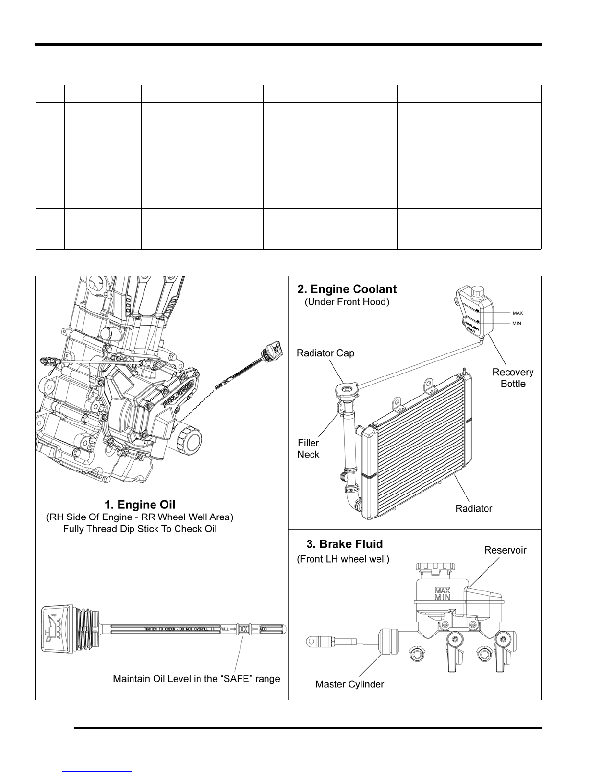
1 Engine Oil
Polaris PS-4 Plus
Per
formance Synthetic
4-Cycle Engine Oil
Add oil to proper level on
stick
dip
2 Engine Coolant Polaris 60/40 Coolant
3 Brake Fluid Polaris DOT 4 Brake Fluid
* More often under severe use, such as operated in water or under severe loads.
Maintain coolant level in
olant reservoir bottle
co
Maintain fluid level between
“MAX an
master cylinder reservoir
d “MIN” lines on the
Check level daily, change
coolant every 2 years
Check level during pre-ride
inspection; change fluid every
two years
2.6
9923523 - RANGER RZR 570 Service Manual
© Copyright 2011 Polaris Sales Inc.
Page 21

MAINTENANCE
Maintenance Quick Reference
III. # Item Lube Rec. Method Frequency*
4 Front Gearcase Polaris Demand Drive Plus
5 Transmission
* More often under severe use, such as operated in water or under severe loads.
Polaris AGL Plus
Gearcase Lubricant
Add lubricant until it is visible
at the fill
Add lubricant until it is visible
at the fill
hole threads
hole threads
Check level every 25 hours;
change fluid yearly
Check level every 25 hours;
change lubricant yearly
2
2.7
9923523 - RANGER RZR 570 Service Manual
© Copyright 2011 Polaris Sales Inc.
Page 22

MAINTENANCE
Rear Stabilizer Bar
Prop Shaft
Front Suspension
Rear Suspension
Front Stabilizer Bar
Grease Lubrication Points
There are grease fittings at each A-arms pivot point, each front or rear stabilizer bushing, and on the front propshaft yoke.
Apply grease until all traces of water have been purged out at each of these areas.
Item Recommended Lube Method Frequency
Front Propshaft Yoke(s)
A-arm Pivot Bushings
Stabilizer Bar Bushings
Polaris Premium U-Joint Grease
Grease fittings every 500
mi
les (800 km).
Grease before long periods
o
f storage, and after
thoroughly washing or
submerging the vehicle.
2.8
9923523 - RANGER RZR 570 Service Manual
© Copyright 2011 Polaris Sales Inc.
Page 23

MAINTENANCE
LUBRICANTS / SERVICE PRODUCTS
Polaris Lubricants, Maintenance and Service
Products
Part No. Description
Engine Lubricant
2870791 Fogging Oil (12 oz. Aerosol)
2876244
2876245
2878068
2878069
2878070
2877922
PS-4 Plus Synthetic 4-Cycle Engine Oil
uart)
(Q
PS-4 Plus Synthetic 4-Cycle Engine Oil
Gallon)
(
Gearcase / Transmission Lubricants
AGL Plus Gearcase Lubricant
(1 Qt.) (12 Count)
AGL Plus Gearcase Lubricant
(1 Gal.) (4 Count)
AGL Plus Gearcase Lubricant
(2.5 Gal.) (2 Count)
Demand Drive Plus
(Quart)
NOTE: Each item c an b e pu rchased se parately at
your local Polaris dealer.
Part No. Description
Additives / Sealants / Thread Locking Agents / Misc.
2871950
2871326
2870652 Fuel Stabilizer (16 oz.) (12 count)
2872189 DOT 4 Brake Fluid (12 count)
2871557 Crankcase Sealant, 3-Bond 1215 (5 oz.)
NOTE: The nu mber co unt indicated by each part
number
units that are shipped with each order.
Loctite™ Threadlock 242
(6 ml.) (12 count)
Premium Carbon Clean
(12 oz.) (12 count)
in th e t able above ind icates t he numbe r of
2
2877923
2870465 Oil Pump for 1 Gallon Jug
2871312 Grease Gun Kit
2871322
2871423
2871460 Starter Drive Grease (12 Count)
2871515 Premium U-Joint Lube (3 oz.) (24 Count)
2871551 Premium U-Joint Lube (14 oz.) (10 Count)
2871329 Dielectric Grease (Nyogel™)
2871323 60/40 Coolant (Gallon) (6 Count)
2871534 60/40 Coolant (Quart) (12 Count)
Demand Drive Plus
(2.5 Gallon)
Grease / Specialized Lubricants
Premium All Season Grease
(3 oz. cartridge) (24 Count)
Premium All Season Grease
(14 oz. cartridge) (10 Count)
Coolant
2.9
9923523 - RANGER RZR 570 Service Manual
© Copyright 2011 Polaris Sales Inc.
Page 24

MAINTENANCE
Shift Cable
Mount
Dust Boot
Clevis Pin
Shift Cable
Jam Nut (A)
Jam Nut (B)
GENERAL VEHICLE INSPECTION AND MAINTENANCE
Pre-Ride / Daily Inspection
Perform the following pre-ride inspection daily, and when
servicing the vehicle at each scheduled maintenance.
• Tires - check condition and pressures
• Fuel tank - fill to proper
• All brakes - check operation and adjustment
• Throttle - check for free operation and closing
• Headlights/Taillights/Brakelights - also check
ope
ration of all indicator lights and switches
• Ignition switch - check for proper function
• Wheels - check for tightness of wheel nuts and
axle
nuts; check to be sure axle nuts are secured
by cotter pins
• Air cleaner element - check for dirt; replace if
necessar
• Steering - check for free operation noting any
unu
y.
sual looseness in any area
level
Shift Cable Inspection / Adjustment
Shift c able a djustment m ay be ne cessary if sy mptoms
include:
• No AWD or gear position display on instrument
er
clust
• Ratcheting noise on deceleration
• Inability to engage into a
• Excessive gear clash (noise)
• Gear selector moving out of desired range
1. Locate th e shift ca ble in th e r ear r ight-hand whe el
w
ell area.
gear
• Loose parts - visually inspect vehicle for any
dam
aged or loose nuts, bolts or fasteners
• Engine coolant - check for proper level at the
re
covery bottle
• Check all front and rear suspension components
r wear or damage.
fo
Frame, Nuts, Bolts, and Fasteners
Periodically inspect the tor que of all fasten ers in
accordance with the maintenance schedule. Check that all
cotter pins are in place. Refer to specific fastener torques
listed in each chapter.
2. Inspect shift cable, clevis pin, pivot bushings, and dust
t. Replace if worn or damaged.
boo
3. If adjustment is required: Lo
cable out of the mount and rotate jam nut (B).
osen jam nut (A), pull the
2.10
9923523 - RANGER RZR 570 Service Manual
© Copyright 2011 Polaris Sales Inc.
Page 25

MAINTENANCE
WARNING
Fuel Line
4. Adjust the shift cable so there is the same amount of
cable travel when shifting slightly past the detents of
HIGH (H) gear and PARK (P).
5. Thread jam nut (A) or (B) as required to obtain proper
ble adjustment.
ca
NOTE: This procedure may require a few attempts to
tain the proper adjustment.
ob
6. Once the p roper ad justment is obtained, place the
cable and jam nut (B) into the mount. Tighten jam
shift
nut (A) against the mount.
7. Start engine and shift through all gears to ensure the
cable is properly adjusted. If transmission still
shift
ratchets after cable adjustment, the transmission will
require service.
FUEL SYSTEM AND AIR INTAKE
Fuel System
Fuel Line
1. Check the quick-connect fu el line from th e en gine
fuel rail conn ection to th e fu el ta nk connection for
signs of wear, de terioration, da mage or leakag e.
Replace if necessary.
2
2. Be sure fuel line is routed and retained properly.
IMPORTANT: Make sure line is not kinked or pinched.
Gasoline is extremely flammable and explosive
under certain conditions.
Always stop the engine and refuel outdoors or in
a well ventilated area.
Do not smoke or allow open flames or sparks in
r near the area where refueling is performed or
o
where gasoline is stored.
Do not overfill the tank. Do not fill the tank
If you get gasoline in your eyes or if you swallow
soline, seek medical attention immediately.
ga
If you spill gasoline on y
immediately wash it off with soap and water
and change clothing.
Never start the engine or let it run in an enclosed
ea. Engine exhaust fumes are poisonous and
ar
can result in loss of consciousness or
death in a short time.
Never drain the fuel when the engine is hot.
Severe burns
our skin or clothing,
may result.
neck.
3. Replace fuel line every two years.
2.11
9923523 - RANGER RZR 570 Service Manual
© Copyright 2011 Polaris Sales Inc.
Page 26

MAINTENANCE
Fuel Pump Asm
Fuel Line
Throttle Pedal
Fuel Pump / Fuel Filters
The RZR 57 0 e ngine u ses a se rviceable, hi gh-volume,
high-pressure, fuel pump that includes a preliminary filter
and a n in ternal fine filter located be fore th e p ump
regulator.
NOTE: Neither f ilter is se rvicable individua lly. Mu st
place the fuel pump as an assembly.
re
Vent Lines
1. Check fuel tan k, fr ont gearcase an d transmission
vent lines for signs of wear, deterioration, damage or
leakage. Replace every two years.
2. Be sure vent lines are routed and secured properly.
IMPORTANT: Ensure lines are not kinked or pinched.
Throttle Pedal Inspection
If the throttle pedal has excessive play due to cable stretch
or cab le misadju stment, it wil l cause a dela y in throttle
speed. Also, the throttle may not open fully. If the throttle
pedal has no play, the throttle may be hard to control, and
the idle speed may be erratic.
NOTE: Refer to Chapter 4 for fuel pump replacement
a
nd all other information related to the EFI System.
2.12
9923523 - RANGER RZR 570 Service Manual
© Copyright 2011 Polaris Sales Inc.
Check the throttle pedal play periodically in accor dance
with the Per
necessary.
iodic Maintenance Chart and adjust the play if
Page 27

MAINTENANCE
Throttle Body
Boot
A
B
Press In Tabs
Pre-filter Cover
Pre-Filters
Throttle Freeplay Adjustment
Inspection
1. Place the transmission in the P (Park) position.
2. Start the engine, and warm it up thoroughly.
3. Measure the distance the throttle pedal moves before
en gine be gins to increase in RPM . Freeplay
the
should be 1/16” - 1/8” (1.5 - 3 mm).
Adjustment
1. Remove the cargo box access panel to ac
throttle body area.
cess the
4. Re-tighten the jam nut after fina
5. Apply a small am ount of grease to the inside of the
ot and slide it over the cable adjuster to its original
bo
position.
6. Reinstall the cargo box access panel.
l adjustment is made.
Engine and PVT Intake Pre-Filter Service
It is r ecommended that the e ngine and PVT intake prefilter b e in spected daily. T he filter sho uld be inspe cted
using the following procedure:
NOTE: T
just above the left-rear wheel fender.
1. Press “IN” on the intak e grill cover
he engine and PVT inta ke pr e-filter is locate d
tabs and remove
the pre-filter cover to access the pre-filters.
2
2. Locate thro ttle ca ble o n the le ft-hand side o f the
3. Using an o pen-end wrench, lo osen the a djustment
NOTE: While adj usting, li ght
pedal in and out.
thr
ottle body. Slide back the cable adjuster boot.
m nut (A). Using another open-end wrench, move
ja
the cable adjuster (B) until 1/16” to 1/8” (1.5 - 3 mm)
of freeplay is achieved at the throttle pedal.
ly move th e t hrottle
2. Remove and insp ect the p re-filters. If ne cessary,
an with soapy water and dry with compressed air.
cle
3. Reinstall the dry pre-filter s an
cover.
d inst all the pr e-filter
2.13
9923523 - RANGER RZR 570 Service Manual
© Copyright 2011 Polaris Sales Inc.
Page 28

MAINTENANCE
A
Remove Hose
A
Install Hose
Air Filter Service
It is recommended that the air filter be inspected as part of
pre-ride inspection. In extremely dusty conditions, air filter
replacement will be required more often.
The filter shou ld be inspected
procedure:
using the following
4. Inspect the air filter element and replace if necessary.
not attempt to clean the air filter.
Do
NOTE: If the filter has been soaked with fuel or oil it
st be replaced.
mu
NOTE: Service more frequently if vehicle is operated
in wet
extended periods.
Installation
1. Clean the air box and air box cover thoroughly.
2. Place the filter into the air box with the air filter pleats
cond itions o r at hig h th rottle ope ration f or
cing UP, as shown.
fa
Removal
NOTE: Th
access panel.
1. Thoroughly clean the air box area to remove dirt and
2. Loosen hose clamp (A) and remove the intake hose
3. Unlatch the (6) clips and carefully remove the air box
e air box is located underneath the cargo box
ebris.
d
m the air box cover.
fro
cover. Be sure not
air filter element during removal.
to let the air box cover contact the
3. Carefully install air box cover and secure with the (6)
c
lips.
4. Reinstall the clea n intake h ose a nd tigh ten ho se
c
lamp (A).
5. Reinstall the cargo box access cover.
2.14
9923523 - RANGER RZR 570 Service Manual
© Copyright 2011 Polaris Sales Inc.
Page 29

Air Box / Air Filter Exploded View
Clip (6)
Boot
Air Intake Duct
Air Intake
Air Filter
Clamps
Clamp
Clamp
Air Box Cover
Box
Grommets
Mount
Drain
Clamp
Engine Pre-filter
PVT Pre-filter
Intake Baffle Box
Remove Hose From Air Box
Cover for Filter Removal
MAINTENANCE
2
9923523 - RANGER RZR 570 Service Manual
© Copyright 2011 Polaris Sales Inc.
2.15
Page 30

MAINTENANCE
WARNING
Maintain Oil Level In SAFE Range
DO NOT Overfill the Engine
ENGINE
Engine Oil Level
This single cylinder engine is a wet-sump engine, meaning
the o il is co ntained in t he bo ttom of th e cr ankcase. To
check the oil level follow the procedure listed below:
IMPORTANT: Thoroughly clean engine around the oil
ain plug, oil filte r and oil dip stick to prevent
dr
contamination from entering the engine.
1. Position vehicle on a level surface.
2. Place the transmission in Park (P).
3. Be sure engine OFF has not been run for at lease 3
utes.
min
IMPORTANT: Do not run the machine and then
immediat
4. Locate the engine oil dipstick:
ely check the oil level.
• RZR 57
engine case; accessible through the righthand rear wheel well area.
0 - Located on the right-hand side of the
8. Unscrew and remove dipstick and verify the oil level
is
in the SAFE (XX) range. Add oil as indicated by the
level on the dips tick. D o not overfill (see N OTE
below!).
NOTE: A rising oil level bet ween ch ecks in cool
ther driving can indicate contaminants suc h as
wea
gas or moisture collecting in the crankcase. If the oil
level is ov er t he f ull mar k, cha nge t he o il
immediately.
9. Reinstall the dipstick and hand tighten.
Engine Oil and Filter Service
Always change engine oil and filter at the intervals outlined
in the Periodic Maintenance Chart. Always change the oil
filter whenever changing the engine oil.
5. Thoroughly clean the engine around dipstick area.
6. Unscrew / remove dipstick and wipe dry with a clean
cloth.
7. Reinstall the dipstick completely.
NOTE: Make certain the dipstick is thr eaded all the
into the engine case.
way
IMPORTANT: Thoroughly clean engine around the oil
drain plug, oil f
contamination from entering the engine.
Personal injury can occur when handling used
oil. Hot oil can cause burns or skin damage.
PS-4 Plus Synthetic 4-Cycle Engine Oil
1. Position vehicle on a level surface.
2. Place the transmission in PARK (P).
ilter an d oil dipst ick t o prev ent
Recommended Engine Oil:
(
PN 2876244) (Quart)
2.16
9923523 - RANGER RZR 570 Service Manual
© Copyright 2011 Polaris Sales Inc.
Page 31

MAINTENANCE
CAUTION
Drain Plug
NOTE: Drain plug is accessed
through the skid plate.
Oil Filter
= T
3. If needed, start the engine and allow it to idle for three
minutes until warm. Stop the engine.
4. Place a d rain pa n b eneath e ngine cr ankcase a nd
emove the drain plug.
r
Oil may be hot. Do not allow hot oil to come into
contact with skin, as serious burns may result.
5. Allow oil to drain completely.
6. Replace sealing washer on drain plug.
NOTE: The sealing surface on the drain plug should
be
clean and free of burrs, nicks or scratches.
7. Reinstall drain plug and torque to 1
8. Place a drain pan under vehicle below the oil filter.
9. Place sho p towels beneath oil filter. U
Wrench (PU-50105) and a 3/8” extension, turn the oil
filter counter-clockwise to remove it.
2 ft. lbs. (16 Nm).
sing Oil Filter
11. Lubricate O-ring on n ew filter with a film o f fre sh
gine oil. Check to make sure the O-ring is in good
en
condition.
12. Install new filter an d tur n by hand u ntil filter gasket
ntacts the sealing surface, then turn an additional
co
1/2 turn.
13. Remove the engine o il dipstick (see “Eng ine Oil
vel”).
Le
14. Using a long funnel, fill the sump with 2 qts. (1.9 l) of
4 Plus Synthetic Engine Oil (2876244).
PS-
Crankcase Drain Plug Torque:
12 ft. lbs. (16 Nm)
Oil Filter Torque:
Turn by hand until filter gasket contacts sealing
surface, then turn an additional 1/2 turn
Oil Filter Wrench:
PU-50105: 2.5” (64 mm)
15. Verify the transmission is still
16. Start the engine and let it idle for two minutes.
17. Stop the engine and inspect for leaks.
18. Re-check the oil level on the dipstick and add oil as
n
ecessary to bring the level to the upper mark on the
dipstick.
19. Dispose of used oil and oil filter properly.
positioned in PARK (P).
2
10. Using a clean dry cloth, clean filter sealing surface on
the crankcase.
2.17
9923523 - RANGER RZR 570 Service Manual
© Copyright 2011 Polaris Sales Inc.
Page 32

MAINTENANCE
Breather
Hose
Engine Breather Hose Inspection
The engine is equipped with a breather hose. Inspect the
breather hose fo r po ssible kinks or we ar. The hose is
form fitted for a proper fit. Follow the breather hose from
the engine crankcase to the a ir intake baffle box on the
left-hand rear fender panel.
NOTE: Make sure line is not kinked or pinched.
Valve Clearance Inspection
IMPORTANT: Valve cl earance i nspection should be
performed on a cold engine, at room temperature.
1. Remove the seats and disconn ect th e ne gative ( -)
y cable.
batter
2. Remove the cargo box access panel.
3. Remove the spar k plug wire from the en gine an d
ove the spark plug. Place a clean shop towel into
rem
the spark plug tube to prevent debris from entering the
combustion chamber.
4. Remove the (3) T40 bolts retaining the valve cover.
5. Remove the valve cover from the engine out of the
t-hand rear wheel well area.
righ
Engine and Transmission Mounts
Periodically inspect engine and transmission mounts for
cracks or damage.
Refer to Chapter 3 “Engine Assembly
mounting fastener torque values.
and Installation” for
Compression Test Specification
NOTE: This en gine does ha ve decompression
components.
A smooth idle generally indicates
engine compression is rarely a factor in running condition
problems above idle speed.
Cylinder Compression:
80 - 120 psi (decompression)
good compression. Low
6. Remove the outer PVT cover and drive belt as shown
in ch
apter 6.
2.18
9923523 - RANGER RZR 570 Service Manual
© Copyright 2011 Polaris Sales Inc.
Page 33

MAINTENANCE
7. Rotate th e drive clu tch co unter-clockwise until the
cam chain sprocket timing marks are aligned with the
gasket sur face as sho wn (see Ch apter 3 for mo re
TDC setting procedures).
IMPORTANT: Intake ca m s procket sh ould ha ve “I”
ks
mar
cam spr ocket shou ld hav e “E” ma rks aligned with
gasket surface.
8. Measure th e valve clearance of each valve using
aligned with ga sket surface a nd the ex haust
Image for Reference Only
I
thickness (feeler) gauge. Record the measurement if
clearance is out of specification.
I
E
E
a
9. If the valve clearance is out o
to “Valve Clearance Adjustment” (see Chapter 3).
f specification, proceed
= In. / mm.
Intake Valve Clearance (cold):
.005-.007 in. (0.125-0.175 mm)
= In. / mm.
Exhaust Valve Clearance (cold):
.008-.010 in. (0.152-0.254 mm)
10. Repeat steps 8- 9 u ntil all (4) valves h ave b een
spected.
in
11. Inspect the valve cover seal and replace if necessary.
12. Install the valve cover and spark plug as outlined in
Chapter
13. Install d rive b elt an d o uter clu tch cover a nd ( 8)
re
3.
taining screws (see Chapter 6)
2
= T
Outer Clutch Cover Screws:
45-50 in. lbs. (5 Nm)
14. Connect the negative (-) battery cable to the battery.
15. Start the engine to ensure proper operation.
16. Reinstall the cargo box access panel and seats (see
Chapter
5).
2.19
9923523 - RANGER RZR 570 Service Manual
© Copyright 2011 Polaris Sales Inc.
Page 34

MAINTENANCE
WARNING
40 in. lbs.
(4.5 Nm)
18 ft. lbs.
(24.5 Nm)
Gaskets and Seals -
Replace Each Time Component is Removed
18 ft. lbs.
(24.5 Nm)
Exhaust - Spark Arrestor
Do not clean spark arrestor immediately after the
engine has been run, as the exhaust system
becomes very hot. Serious burns could result from
contact with the exhaust components. Allow
components to cool sufficiently before proceeding.
Wear eye protection and gloves.
Never run the engine in an enclosed area. Exhaust
ntains poisonous carbon monoxide gas that can
co
cause loss of consciousness or death in a very
short time.
Periodically clean spark arrestor to remove accumulated carbon.
1. Allow engine and exhaust system to completely cool.
2. Remove the retaining screw, washer and spark arrestor from the end of the silencer.
3. Use a non-synthetic brush to clean the arrestor screen.
4. Inspect the screen for wear and damage. Replace if needed.
5. Reinstall the arrestor and torque the screw to 40 i
n. lbs. (4.5 Nm).
2.20
9923523 - RANGER RZR 570 Service Manual
© Copyright 2011 Polaris Sales Inc.
Page 35

MAINTENANCE
= T
TRANSMISSION AND FRONT GEARCASE
Specification Chart
Gearcase Lubricant Capacity Fill / Drain Plug Torque
Transmission AGL Plus Gearcase Lubricant 44 oz. (1300 ml) 10-14 ft. lbs. (14-19 Nm)
Transmission (INTL) AGL Plus Gearcase Lubricant 41 oz. (1200 ml) 10-14 ft. lbs. (14-19 Nm)
Front Gearcase Demand Drive Plus 6.75 oz. (200 ml) 8-10 ft. lbs. (11-14 Nm)
Transmission Lubrication
2
NOTE: It is important to f ollow t he t ransmission
maintenance inte rvals de scribed in the Periodic
Maintenance Chart . Regular lu bricant leve l
inspections should be performed as well.
The transmission lubricant level should be che cked and
nged in accordance with the maintenance schedule.
cha
• Be sur e ve hicle is po sitioned on a level su rface
en checking or changing the lubricant.
wh
• Check vent hose to be sure it
and unobstructed.
Transmission Lubricant Level Check
The fill plug is located on the rear portion of the
transmission gearcase. Access
the vehicle. Maintain lubricant level even with the bottom
of the fill plug hole.
1. Position vehicle on a level surface.
2. Remove the fill plug and check the lubricant level.
is routed properly
the fill plug at the rear of
3. If lubricant level is not even with the bottom threads,
dd the r ecommended lubricant as needed. Do not
a
overfill.
4. Reinstall the fill plug and torque
Fill / Drain Plug Torque:
10-14 ft. lbs. (14-19 Nm)
to specification.
2.21
9923523 - RANGER RZR 570 Service Manual
© Copyright 2011 Polaris Sales Inc.
Page 36
MAINTENANCE
=
= T
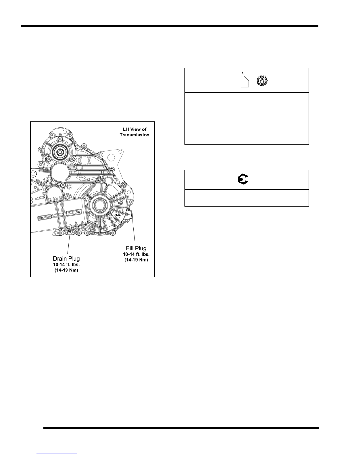
Transmission Lubricant Change
The drain plug is located on the
gearcase. Access the drain plug through the drain hole in
the skid plate.
1. Remove the fill plug (refer to “Transmission
Level Check”).
2. Place a drain pan under the transmission drain plug.
3. Remove d rain p lug and allo w lub ricant to dr ain
completely.
bottom of the transmission
Lubricant
6. Add the recommended amount of lubricant thro ugh
the fill plug
bottom of the fill plug hole w hen filling the
transmission. Do not overfill.
Recommended Transmission Lubricant:
7. Reinstall fill plug with a ne
specification.
hole. Maintain the lubricant level at the
AGL Plus Gearcase Lubricant
(PN 2878068) (Quart)
Capacity: 44 oz. (1300 ml)
Capacity (INTL): 41 oz. (1200 ml)
w O-r ing a nd tor que to
Fill / Drain Plug Torque:
10-14 ft. lbs. (14-19 Nm)
4. Clean the drain plug magnetic surface.
5. Reinstall drain plug with a ne
specification.
w O-ring and torque to
8. Check for leaks. Dispose of used lubricant properly.
2.22
9923523 - RANGER RZR 570 Service Manual
© Copyright 2011 Polaris Sales Inc.
Page 37

MAINTENANCE
= T
Front Gearcase Lubrication
NOTE: It is important to fo llow the fro nt gea rcase
maintenance inte rvals de scribed in the Periodic
Maintenance Chart . Regular fluid leve l ins pections
should be performed as well.
The fron t gearcase fluid le vel should be checked and
nged in accordance with the maintenance schedule.
cha
• Be sur e ve hicle is po sitioned on a level su rface
en checking or changing the fluid.
wh
• Check vent hose to be sure it
and unobstructed.
Front Gearcase Fluid Level Check
The fill plug is located on the bottom
gearcase. Access the fill plug through the right front wheel
well. Maintain fluid level even with the bottom of the fill plug
hole.
1. Position vehicle on a level surface.
2. Remove the fill plug and check the fluid level.
is routed properly
right side of the front
4. Reinstall the fill plug and torque to
Fill / Drain Plug Torque:
8-10 ft. lbs. (11-14 Nm)
Front Gearcase Fluid Change:
The d rain pl ug is locate d on th e bo ttom of th e fro nt
rcase. Access the drain plug through the access hole
gea
in the frame underneath the front gearcase.
1. Remove the fill plug (refer to “Front Gearcase Fluid
Level Chec
2. Place a drain pan under the front gearcase drain plug.
3. Remove th e dr ain plug and allo w fl uid to drain
completely
k”).
.
specification.
2
3. If fluid level is not even with the bottom threads, add
the recommended fluid
as needed. Do not overfill.
4. Clean the drain plug magnetic surface.
5. Reinstall drain plug with a new
specification.
9923523 - RANGER RZR 570 Service Manual
© Copyright 2011 Polaris Sales Inc.
O-ring and torque to
2.23
Page 38

MAINTENANCE
=
= T
6. Add the recommended amount of fluid through the fill
hole. Maintain the fluid le vel ev en wit h t he b ottom
threads of the fill plug hole.
Recommended Front Gearcase Fluid:
Polaris Demand Drive Plus
(PN 2877922) (Quart)
Capacity: 6.
7. Reinstall fill plug with a ne
specification.
Fill / Drain Plug Torque:
8-10 ft. lbs. (11-14 Nm)
8. Check for leaks. Dispose of used fluid properly.
75 oz. (200 ml)
w O- ring an d tor que to
2.24
9923523 - RANGER RZR 570 Service Manual
© Copyright 2011 Polaris Sales Inc.
Page 39

COOLING SYSTEM
Water Pump
Upper Engine Hose
Lower Engine
Hose
Bypass Hose
Radiator
Recovery
Bottle
Upper Radiator
Hose
Pressure Cap
Filler Neck
Hoses
Cooling Fan
Cooling System Exploded View
MAINTENANCE
2
2.25
9923523 - RANGER RZR 570 Service Manual
© Copyright 2011 Polaris Sales Inc.
Page 40

MAINTENANCE
Recovery Bottle
Pressure Cap
WARNING
Cooling System Overview
The engine coolant level is controlled, or maintained, by
the recovery system. The re covery system components
are the recovery bo ttle, radiator filler neck, radiator
pressure cap and connecting hose.
As coola nt op erating tem perature in creases, the
xpanding ( heated) excess coola nt is for ced o ut of the
e
radiator past the pressure cap and into the recovery bottle.
As engine coolant temperature decreases the contracting
(cooled) coolant is drawn back up from the tank past the
pressure cap and into the radiator.
NOTE: Some coolant level drop on new machines is
rmal as the system is purging itself of trapped air.
no
Observe coolan t lev els of ten during the brea k-in
period.
NOTE: Overheating of engine could oc cur if air is
t fully purged from system.
no
Polaris Premium 60/40 is already premixed and ready to
e. Do not dilute with water.
us
Coolant Level Inspection
The pressure cap and recovery bottle are located under
the front hood of the vehicle. The coolant level must be
maintained be tween th e minimum and maximum levels
indicated on the recovery bottle.
4. If the coolant level is below the MIN line, inspect the
co
olant level in the radiator.
NOTE: If o verheating is e vident, allow system to
cool comp
radiator and inspe ct f or s igns of trapped a ir in
system.
cause severe burns. The engine must be cool
5. Remove the pr essure ca p. Using a funnel, ad d
oolant to the top of the filler neck.
c
6. Reinstall the pressure cap.
NOTE: Use of a non-standard pressure cap will not
allo
w the recovery system to function properly.
7. Remove recovery bottle cap and add coolant using a
fu
8. Fill recov ery bottle to M AX
premix Anti Freeze/Coolant or 50/50 or 60/40 mixture
of antifreeze and distilled water as required for freeze
protection in your area.
9. Reinstall the recovery bottle cap.
10. If co olant was re quired, sta rt eng ine an d check for
leaks. Ma
overheating.
letely and ch eck coolant leve l in th e
Never remove the pressure cap when the
engine is warm or hot. Escaping steam can
before removing the pressure cap.
nnel.
level w ith Polaris 60/40
ke su re radiator fins ar e clea n to pre vent
With the en gine at o perating temp
level should be between the upper and lower marks on the
coolant re covery bo ttle. If no t, per form the fo llowing
procedure:
1. Position the vehicle on a level surface.
2. Remove the hood from the front cab.
3. View the coolant level in the recovery bottle.
erature, the coolant
2.26
Cooling System Pressure Test
Refer to Ch apter 3 fo r co oling sy stem pressure tes t
procedure.
9923523 - RANGER RZR 570 Service Manual
© Copyright 2011 Polaris Sales Inc.
Page 41

MAINTENANCE
CAUTION
Antifreeze Hydrometer
WARNING
Drain Here
Coolant Strength / Type
Test th e str ength of the co olant u sing a n an tifreeze
hydrometer.
• A 50/50 or 60/40 mixture of antifre
water will provide the optimum c ooling, corrosion
protection, and antifreeze protection.
• Do n ot use t ap water , stra ight a ntifreeze, or
stra
ight water in th e system. T ap water co ntains
minerals an d impu rities wh ich build up in the
system.
• Straight water or antifree
to freeze, corrode, or overheat.
Polaris Premium Antifreeze
2871534 - Quart
2871323 - Gallon
ze may cause the system
eze and distilled
Coolant Drain / Fill
Coolant Drain
1. Remove the hood from the front cab.
Never drain the coolant when the engine and
radiator are warm or hot. Hot coolant can cause
severe burns. Allow engine and radiator to cool.
2. Slowly remove the pressure cap to relieve any cooling
em pressure.
syst
3. Place a su itable drain pan underneath the rad iator
fitting on
4. Drain the coolant from the radiator by rem oving the
ower co olant ho se fro m the ra diator a s shown.
l
Properly dispose of the coolant.
the front right-hand side of the vehicle.
2
Cooling System
1. Inspect all hoses fo r cracks, d eterioration, abrasion
or leaks. Replace if necessary.
Do not over-tighten hose clamps at radiator,
or radiator fitting may distort, causing a
restriction to coolant flow.
Radiator hose clamp torque is 36 in. lbs. (4 Nm).
2. Check tightness of all hose clamps.
5. Allow coolant to completely drain.
6. Place a su itable d rain pan underneath t he lo wer
ngine hose on the right-hand rear side of the vehicle.
e
2.27
9923523 - RANGER RZR 570 Service Manual
© Copyright 2011 Polaris Sales Inc.
Page 42

MAINTENANCE
= T
= T
7. Remove the h ose and completely drain the engine.
Reinstall the lower coolant hose.
8. Properly dispose of the coolant.
9. Remove the pressure cap. Using a funnel, add the
recommended c
fill the recovery bottle to the MAX level.
10. Refer to Chapter 3 for the “Cooling System Bleeding
ocedure”.
Pr
oolant to the top of the filler neck and
Polaris Premium Antifreeze
2871534 - Quart
2871323 - Gallon
FINAL DRIVE / WHEEL AND TIRE
Wheel and Hub Torque Table
Wheel Nuts:
Steel Wheels: 27 ft. lbs. (37 Nm)
Aluminum Wheels: 30 ft. lbs. + 90° (1/4 turn)
Hub Retaining Nuts:
80 ft. lbs. (108 Nm)
NOTE: Do not lubricate the stud or the lug nut.
Wheel Removal
1. Position the vehicle on a level surface.
2. Place the tra nsmission in PARK (P) and stop th e
ine.
eng
3. Loosen the wheel nuts slightly. If wheel hub removal
equired, remove the cotter pin and loosen the hub
is r
nut slightly.
4. Elevate the appropriate side of the vehicle by placing
suitable stand under the frame.
a
5. Remove the wheel nuts and remove the wheel.
6. If hub removal is re quired, remove the hub nut and
shers.
wa
2.28
9923523 - RANGER RZR 570 Service Manual
© Copyright 2011 Polaris Sales Inc.
Page 43

MAINTENANCE
CAUTION
Wheel Nuts (4)
Hub Nut
Use a new
cotter pin
Note
Tire Rotation
Val v e stem
facing outward
(RZR Only)
WARNING
Tread
Depth 1/8" (3 mm)
Wheel Installation
1. Verify the transmission is still in PARK (P).
2. Install th e wh eel hub, washe rs, an d hub n ut, if
reviously removed.
p
3. Place the wheel in the correct position on the wheel
ub. Be sure the valve stem is toward the outside and
h
rotation arrows on the t ire point towa rd fo rward
rotation.
4. Attach the wheel nuts and finger tighten them.
5. Carefully lower the vehicle to the ground.
6. Torque the whee l nuts and/or hub nut to the proper
que specification listed in the tor que table at the
tor
beginning of this section.
7. If hub nut was removed, install a ne
the hub nut has been tightened.
w cotter pin after
Tire Inspection
• Improper tire inflation may affect vehicle
maneuverability.
• When replacing a tire always use original
uipment size and type.
eq
• The use of non-standard size or type tires may
ffect vehicle handling.
a
Operating with worn tires will increase the
possibility of the vehicle skidding easily with
possible loss of control.
Worn tires can cause an accident.
Always replace tires when the tread depth
easures 1/8", (.3 cm) or less.
m
Tire Tread Depth
Replace tires when tread depth is worn to 1/8" (3 mm) or
.
less
2
If wheels are improperly installed it could affect
vehicle handling and tire wear. On vehicles with
tapered rear wheel nuts, make sure tapered end
of nut goes into taper on wheel.
2.29
9923523 - RANGER RZR 570 Service Manual
© Copyright 2011 Polaris Sales Inc.
Page 44

MAINTENANCE
CAUTION
Front Boots
Rear Boots
WARNING
WARNING
Tire Pressure
Maintain proper tire pressure.
Refer to the warning tire pressure decal
applied to the vehicle.
Tire Pressure Inspection (Cold)
Front Rear
10 psi (55 kPa) 12 psi (55 kPa)
Drive Shaft Boot Inspection
Inspect the drive shaft boots for damage, tears, wear or
leaking grease. If the boots exhibit any of these symptoms,
they should be replaced. Refer to Chapter 7 for drive shaft
boot replacement.
ELECTRICAL AND IGNITION SYSTEM
Battery Maintenance
Keep battery terminals and connections free of corrosion.
If cleaning is necessary, remove the corrosion with a stiff
wire brush. Wash with a solution of one tablespoon baking
soda and one cup water. Rinse well with tap water and dry
off with c lean shop towels . Coat the terminals with
dielectric grease or petroleum jelly.
CALIFORNIA PROPOSITION 65 WARNING:
Batteries, battery posts, terminals and related
accessories contain lead and lead compounds,
and other chemicals known to the State of
California to cause cancer and birth defects or
other reproductive harm.
WASH HANDS AFTER HANDLING.
Battery electrolyte is poisonous. It contains
sulfuric acid. Serious burns can result from
contact with skin, eyes or clothing. Antidote:
External: Flush with water.
Internal:
Follow with milk of magnesia, beaten egg, or
Eyes: Flus
Ventilate when charging or using in an enclosed
NOTE: Batteries must be fully charged before use or
tery life will b e re duced by 10 -30% of fu ll
bat
potential. Ch arge battery acc ording t o “Charging
Procedure” provided in Cha pter 1 0. Do not u se the
vehicle’s stator/alternator to charge a new battery.
Drink large quantities of water or milk.
vegetable oil. Call physician immediately.
h with water for 15 minutes and get
prompt medical attention.
Batteries produce explosive gases.
Keep sparks
space. Always shield eyes when
KEEP OUT OF REACH OF CHILDREN.
, flame, cigarettes, etc. away.
working near batteries.
2.30
9923523 - RANGER RZR 570 Service Manual
© Copyright 2011 Polaris Sales Inc.
Page 45

MAINTENANCE
CAUTION
Battery Removal
1. Remove the driver’s seat to access the battery.
2. Disconnect the (2) black (neg
3. Disconnect the (2) red (positive) battery cables.
4. Remove the hold-down strap and lift th e battery out
the vehicle.
of
ative) battery cables.
Battery Installation
IMPORTANT: Using a new battery that has not been
fully charged can damage the battery and result in a
shorter life . It can a lso hinder v ehicle pe rformance.
Follow the battery charging procedure in Chapter 10
“Electrical” before installing the battery.
1. Ensure the battery is fully charged.
2. Place the battery in the battery holder and secure with
old-down strap.
h
3. Coat the terminals with dielectric grease or petroleum
elly.
j
4. Connect and tighten the (2) re
5. Connect a nd tighten the ( 2) black ( negative) cable
ast.
l
d (positive) cables first.
2
To reduce the chance of sparks: Whenever
removing the battery, disconnect the black
(negative) cable first. When reinstalling the
battery, install the black (negative) cable last.
rify that cables are properly routed and reinstall the
6. Ve
driver’s seat.
Battery Off Season Storage
Refer to Chap ter 10 “Electrical” for o ff sea son stor age
procedures.
2.31
9923523 - RANGER RZR 570 Service Manual
© Copyright 2011 Polaris Sales Inc.
Page 46

MAINTENANCE
WARNING
Note for
reassembly
Inspect electrode for
wear and buildup
Gap - .0276 - .0315" (0.7 - 0.8 mm)
Spark Plug Gap
Spark Plug Service
1. Remove the dr iver’s sea t a nd d isconnect th e ( -)
negative battery cable from the battery.
2. Remove cargo box access panel.
A hot exhaust system and engine can cause
serious burns. Allow engine to cool or wear
protective gloves when removing the spark plugs.
3. Clean top of engine to remove all dirt and debris.
4. Remove the spark plug wire from the engine.
8. Measure gap with a wire gauge. Adjust gap if
ecessary by carefully bending the side electrode.
n
9. If n ecessary, r eplace spa rk p lug with p roper type.
C
AUTION: Severe engine damage may occur if the
incorrect spark plug is used.
10. Apply Anti-seize compound to the spark plug threads.
11. Install spark plugs and torque to specification.
Recommended Spark Plug:
Champion RG4YCX
Spark Plug Torque:
7 ft. lbs. (10 Nm)
Apply Anti-seize
5. Remove spark plug.
6. Inspect electrodes for wear and carbon buildup. Look
a sharp outer edge with no rounding or erosion of
for
the electrodes.
7. Clean with electrical contact cleaner only.
12. Install spark plug wire into spark plug / engine.
13. Reinstall cargo box access panel.
14. Reinstall the (- ) negative b attery cab le a nd driver’s
at.
se
2.32
9923523 - RANGER RZR 570 Service Manual
© Copyright 2011 Polaris Sales Inc.
Page 47

MAINTENANCE
Engine
Ground Cable
Chassis
Ground Terminal
WARNING
Engine To Frame Ground
Inspect ground cable connections. Be sure they are clean
and tight.
The engine ground cable runs from the upper starter motor
unting bolt to the chassis ground terminal.
mo
The Chassis ground is located under the drivers seat, near
starter solenoid.
the
STEERING
Steering Inspection
The steering components should be checked periodically
for lo ose fa steners, wor n tie ro d e nds, b all jo ints, and
damage. Also ch eck to make sure all cotter pins are in
place. If cotte r pins are re moved, they mu st not be re–
used. Always use new cotter pins.
Replace any wor n or da maged steer ing com ponents.
teering should move freely through the entire range of
S
travel without binding. Check routing of all cables, hoses,
and wirin g to b e sur e the steer ing mech anism i s n ot
restricted or limited.
NOTE: Whenever s teering c omponents are
ed, check front end alignment.
replac
Due to the critical nature of the procedures
outlined in this chapter, Polaris recommends
steering component repair and adjustment be
performed by an authorized Polaris
MSD certified technician.
Use only genuine Polaris replacement parts.
2
2.33
9923523 - RANGER RZR 570 Service Manual
© Copyright 2011 Polaris Sales Inc.
Page 48

MAINTENANCE
Tie Rod
U-Joints
Gearbox
Tie Rod
Check for Loose Wheel or Hub
Steering Wheel Freeplay
Check t he st eering wh eel f or specified freeplay and
operation.
1. Position the vehicle on level ground.
2. Lightly turn the steering wheel left and right.
3. There should be 0.8”-1.0” (20-25 mm) of freeplay.
4. If there is exce ssive fr eepla
rough, inspect the following components.
• Tie Rod Ends
• Steering Shaft U-Joints
• Steering Gearbox
y or the stee ring feels
Tie Rod End / Wheel Hub Inspection
• To check for play in the tie rod end, grasp the
steering tie rod, pull in all directions feeling for
movement.
• Replace any worn steering components. Steering
ld move freely through entire range of travel
shou
without binding.
• Elevate front end of machine so front wheels ar e
of
f the ground. Che ck fo r a ny lo oseness in fr ont
hub/wheel assemb ly by g rasping the tir e firmly at
top and bottom first, and then at front and rear. Try
to move the wheel and hub by pushing inward and
pulling outward.
2.34
• If abnormal movement is detected, inspect the hub
d whe el assemb ly to deter mine the cau se
an
(loose wheel nuts or loose front hub nut).
• Refer to Chap ter 7 “ Final Drive” for fro nt hu b
ser
vice procedures.
9923523 - RANGER RZR 570 Service Manual
© Copyright 2011 Polaris Sales Inc.
Page 49

MAINTENANCE
= In. / mm.
CAUTION
Wheel Toe Alignment Inspection
1. Place ma chine o n a smooth le vel su rface and set
steering wh eel in a str aight ah ead position . Secure
the steering wheel in this position.
2. Place a chalk mark on the cente
approximately 10” (25.4 cm) from the floor or as close
to the hub/axle center line as possible.
r line of the front tires
Wheel Toe Adjustment
If to e alig nment is inco rrect, mea sure th e dist ance
between vehicle center and each wheel. This will tell you
which tie rod needs adjusting.
2
NOTE: It is impor tant t he h eight of b oth mark s be
e
qually positioned to get an accurate measurement.
3. Measure the distance between the marks and record
measurement. Call this measurement “A”.
the
4. Rotate the tires 180
Position chalk marks facing rearward, even with the
hub/axle center line.
5. Again measure the distance between the marks and
cord. Call t his m easurement “ B”. Su btract
re
measurement “ B” from me asurement “ A”. The
difference between measurements “A” and “B” is the
vehicle toe alignment. The recommended vehicle toe
tolerance is 1/8”, to 1/4”, (.3 to .6 cm) toe out. This
means the measurement at the front of the tire (A) is
1/8”, to 1/4”, (.3 to .6 cm) wider than the measurement
at the rear (B).
(A) - (B) = 1/8 - 1/4" (.3 to .6 cm)
° by moving the vehicle forward.
Wheel Toe-Out:
NOTE: Be sure st eering wheel is st raight ahead
ore determining which tie rod needs adjustment.
bef
During tie rod adjustment, it is very important that
the following precautions be taken when
tightening tie rod end jam nuts.
If the rod end is positioned incorrectly it will not
pivot, and may break.
2.35
9923523 - RANGER RZR 570 Service Manual
© Copyright 2011 Polaris Sales Inc.
Page 50

MAINTENANCE
= T
WARNING
Increase
Preload
Decrease
Preload
Cam
To adjust toe alignment:
• Hold tie rod end to keep it from rotating.
• Loosen jam nuts at both end of the tie rod.
• Shorten or lengthen the tie rod until alignment is as
re
quired to achieve the pr oper toe settin g as
specified in “Wheel Toe Alignment”.
• IMPO
• After alignment is complete, torque jam nuts to
RTANT: When tightening the tie rod end jam
nuts, the rod ends must be held parallel to prevent
rod e nd da mage and p remature wear. Dama ge
may not be immed iately app arent if done
incorrectly.
pecification.
s
Tie Rod Jam Nut Torque:
12-14 ft. lbs. (16-19 Nm)
SUSPENSION
Spring Preload Adjustment
The front and rear shock absorber springs are adjustable
by rotating the adjustment cam to change spring tension
preload.
Uneven adjustment may cause poor handling of the
vehicle, which could result in an accident and
serious injury or death. Always adjust both the left
and right spring preloads equally.
Suspension Spring Adjustment
1. Position the vehicle on a lev el su rface and stop the
ine.
eng
2. Raise and safely su pport th e fr ont or rear of th e
ve
hicle off the ground to allow the suspension to fully
extend.
NOTE: The tires should not be touching the ground.
3. To adjust the suspension, rotate the
clockwise to incr ease spr ing ten sion or counterclockwise to decrease spring tension.
Shock Spanner Wrench
(PN 2871095)
4. Each notch of the adjustment will add 6% - 8% more
load to the spring over the primary position.
pre
adjustment cam
2.36
9923523 - RANGER RZR 570 Service Manual
© Copyright 2011 Polaris Sales Inc.
Page 51

MAINTENANCE
Master Cylinder
Maximum
Minimum
Measure Pad Material
Service Limit:
.040" (1 mm)
Thickness
Measure Brake Disc Thickness
Service Limit:
.170" (4.32 mm)
Front
Disc
Rear
Disc
BRAKE SYSTEM
Brake Fluid Inspection
Always check the brake pedal travel and inspect the brake
fluid reservoir level before each operation. If the fluid level
is low, add DOT 4 brake fluid only.
Brake fluid should be changed every two years. The fluid
uld also be chan ged anytime th e fluid becomes
sho
contaminated, the fluid level is below the minimum level,
or if th e type and br and of th e flu id in the reservoir is
unknown.
The brake fluid master cylinder re
through the left front wheel well.
1. Position the vehicle on a level surface.
2. Place the transmission in PARK (P).
3. View the brake fluid level in the reservoir. The level
uld be between the MAX and MIN level lines.
sho
4. If the fluid level is lower than
brake fluid until it reaches the MAX level line.
servoir can be accessed
the MIN level line, add
Brake Pad / Disc Inspection
1. Check the br ake pa ds for wear, dam age, or
looseness.
2. Inspect th e br ake p ad we ar su rface for e xcessive
wear.
3. Pads should be changed when the
worn to .040” (1 mm).
4. Check surface condition of the brake discs.
friction material is
2
5. Install th e re servoir ca p and
forcefully fo r a fe w se conds a nd ch eck for fluid
leakage ar ound the master cylinder fittings an d the
brake caliper fittings.
apply the br ake pe dal
5. Measure the th ickness o f the front an d re ar bra ke
s.
disc
6. The disc(s) should be replaced if thickness is less than
.170” (4.32 mm).
Brake Hose and Fitting Inspection
Check b rake system hoses and fitting s for cracks,
deterioration, ab rasion, an d leaks. Tighten an y loo se
fittings and replace any worn or damaged parts.
2.37
9923523 - RANGER RZR 570 Service Manual
© Copyright 2011 Polaris Sales Inc.
Page 52

MAINTENANCE
Inboard
Pad
Outboard
Pad
Outboard Pad Thickness
New 0.250” (6.35 mm)
Limit: 0.190” (4.83 mm)
Inboard Pad Thickness
New 0.300” (7.62 mm)
Limit: 0.240” (6.10 mm)
Parking Brake Cable Adjustment (INTL)
When the parking brake is fully engaged and “BRAKE” is
displayed on the instrument clu ster, en gine spe ed is
limited to 1500 RPM while in gear. If throttle is applied, this
limiting fea ture pr events op eration, wh ich pr otects the
parking brake pads from excessive wear.
NOTE: Inspect the parking brake cable tension after
he f irst 25 hours of operation and every 100 hours
t
of operation af terwards to ens ure prop er cab le
tension.
Loss of tension in the p arking brake cable will caus
illumination of the parking brake indicator and activation of
the limiting feature. If this occurs, inspect an d a djust
parking brake cable tension. If performing this service is
difficult due to conditions o r location , temporarily
disconnect the parking brake switch electrical connector.
Reconnect th e co nnector as so on as practicable an d
adjust the parking brake cable to proper tension.
1. Pull back on the parking brake lever (located in dash).
2. After 3 t o 4 clic ks “BRAKE ” should display on the
nstrument cl uster a nd th e whe els of the vehicle
i
should not rotate when turning by hand. After 8 full
clicks of lever travel, the vehicle should not roll while
parked.
3. If the vehicle moves, adjustment is necessary.
4. Adjust the pa rking brake cable wh ere th e ca ble
ttaches to the caliper mount / shift cable bracket. The
a
mount bracket is located on the right-hand side of the
transmission.
e
Parking Brake Pad Inspection (INTL)
Inspect t he p arking br ake ca liper br ake p ad thickness.
Replace brake pads if damaged or worn beyond service
limit. Replac e caliper ass embly if damage or excessive
wear is found. Refer to the following image for brake pad
specifications.
Adjustment Procedure: Refer to Chapter 9 “Brakes”
or complete adjustment procedure.
f
2.38
9923523 - RANGER RZR 570 Service Manual
© Copyright 2011 Polaris Sales Inc.
Page 53

ENGINE / COOLING SYSTEM
CHAPTER 3
ENGINE / COOLING SYSTEM
GENERAL INFORMATION . . . . . . . . . . . . . . . . . . . . . . . . . . . . . . . . . . . . . . . . . . . . . . . . 3.3
SPECIAL TOOLS . . . . . . . . . . . . . . . . . . . . . . . . . . . . . . . . . . . . . . . . . . . . . . . . . . . . . . . 3.3
ENGINE LUBRICATION SPECIFICATIONS . . . . . . . . . . . . . . . . . . . . . . . . . . . . . . . . . . 3.3
OIL PRESSURE TEST . . . . . . . . . . . . . . . . . . . . . . . . . . . . . . . . . . . . . . . . . . . . . . . . . . . 3.4
ENGINE OIL FLOW CHART. . . . . . . . . . . . . . . . . . . . . . . . . . . . . . . . . . . . . . . . . . . . . . . 3.5
ENGINE SERVICE SPECIFICATIONS . . . . . . . . . . . . . . . . . . . . . . . . . . . . . . . . . . . . . . . 3.6
ENGINE SPECIFICATIONS - 1204286 RZR570HO-11 . . . . . . . . . . . . . . . . . . . . . . . . . . 3.6
ENGINE DETAIL - TORQUE VALUES / SEQUENCES / ASSEMBLY NOTES . . . . . . . . 3.8
MAIN ENGINE COMPONENTS - TORQUE SPECIFICATION AND SEQUENCE . . . . . 3.8
CRANKCASE / TIMING CHAIN GUIDES / OIL PICKUP / REGULATOR VALVE . . . . . . 3.9
CYLINDER / OIL FILTER / OIL PUMP / BREATHER. . . . . . . . . . . . . . . . . . . . . . . . . . . 3.10
CAMSHAFTS / CYLINDER HEAD / FLYWHEEL / IDLE
SPARK PLUGS / STARTER / THROTTLE BODY / VALVE COVER . . . . . . . . . . . . . . . 3.12
PISTON / CRANKSHAFT / BALANCE SHAFT. . . . . . . . .
ENGINE COOLING SYSTEM . . . . . . . . . . . . . . . . . . . . . . . . . . . . . . . . . . . . . . . . . . . . . 3.14
COOLING SYSTEM EXPLODED VIEW AND COOLANT FLOW DIAGRAM. . . . . . . . . 3.14
COOLING SYSTEM SPECIFICATIONS. . . . . . . . . . . . . . . . . . . . . . . . . . . . . . . . . . . . . 3.15
COOLING SYSTEM PRESSURE TEST. . . . . . . . . . . . . . . . . . . . . . . . . . . . . . . . . . . . . 3.15
PRESSURE CAP TEST . . . . . . . . . . . . . . . . . . . . . . . . . . . . . . . . . . . . . . . . . . . . . . . . . 3.16
RADIATOR . . . . . . . . . . . . . . . . . . . . . . . . . . . . . . . . . . . . . . . . . . . . . . . . . . . . . . . . . . . 3.16
COOLANT DRAIN / RADIATOR REMOVAL . . . . . . . . . .
THERMOSTAT REPLACEMENT . . . . . . . . . . . . . . . . . .
COOLING SYSTEM BLEEDING PROCEDURE . . . . . . . . . . . . . . . . . . . . . . . . . . . . . . 3.18
WATER PUMP SERVICE . . . . . . . . . . . . . . . . . . . . . . . . . . . . . . . . . . . . . . . . . . . . . . . . 3.20
WATER PUMP COVER AND IMPELLER SERVICE . . . . . . . . . . . . . . . . . . . . . . . . . . . 3.20
WATER PUMP MECHANICAL SEAL / OIL SEAL REPLACEMENT . . . . . . . . . . . . . . . 3.21
ENGINE SERVICE . . . . . . . . . . . . . . . . . . . . . . . . . . . . . . . . . . . . . . . . . . . . . . . . . . . . . 3.26
ACCESSIBLE ENGINE COMPONENTS . . . . . . . . . . . . . . . . . . . . . . . . . . . . . . . . . . . . 3.26
TOP-END SERVICE (ENGINE IN CHASSIS) . . . . . . . . . . . . . . . . . . . . . . . . . . . . . . . . 3.26
ENGINE REMOVAL . . . . . . . . . . . . . . . . . . . . . . . . . . . . . . . . . . . . . . . . . . . . . . . . . . . . 3.27
ENGINE INSTALLATION . . . . . . . . . . . . . . . . . . . . .
ENGINE BREAK-IN PERIOD . . . . . . . . . . . . . . . . . . . . . . . . . . . . . . . . . . . . . . . . . . . . . 3.34
ENGINE MOUNTING AND TORQUE VALUES . . . . . . . . . . .
ENGINE LUBRICATION SPECIFICATIONS
. . . . . . . . . . . . . . . . . . . . . . . . . . . . . . . . . 3.35
SETTING TDC (TOP-DEAD-CENTER) . . . . . . . . . . . . . . . . . . . . . . . . . . . . . . . . . . . . . 3.36
ENGINE DISASSEMBLY / INSPECTION - TOP END . . . . . . . . . . . . . . . . . . . . . . . . . . 3.37
VALVE COVER REMOVAL . . . . . . . . . . . . . . . . . . . . . . . . . . . . . . . . . . . . . . . . . . . . . . 3.37
CAMSHAFT REMOVAL . . . . . . . . . . . . . . . . . . . . . . . . . . . . . . . . . . . . . . . . . . . . . . . . . 3.37
CAMSHAFT SPROCKET INSPECTION . . . . . . . . . . . . . . . . . . . . . . . . . . . . . . . . . . . . 3.39
CAMSHAFT / CAMSHAFT BORE INSPECTION . . . . . . . . . . . . . . . . . . . . . . . . . . . . . . 3.39
EXHAUST CAMSHAFT DECOMPRESSION MECHANISM . . . . . . . . . . . . . . . . . . . . . 3.41
CAM CHAIN AND GUIDE SERVICE . . . . . . . . . . . . . . . . . . . . . . . . . . . . . . . . . . . . . . . 3.41
CYLINDER HEAD REMOVAL . . . . . . . . . . . . . . . . . . . . . . . . . . . . . . . . . . . . . . . . . . . . 3.42
CYLINDER HEAD DISASSEMBLY . . . . . . . . . . . . . . . . . . . . . . . . . . . . . . . . . . . . . . . . 3.42
CYLINDER HEAD INSPECTION . . . . . . . . . . . . . . . . . . . . . . . . . . . . . . . . . . . . . . . . . . 3.44
CYLINDER HEAD WARP INSPECTION . . . . . . . . . . . . . . . . . . . . . . . . . . . . . . . . . . . . 3.44
VALVE INSPECTION . . . . . . . . . . . . . . . . . . . . . . . . . . . . . . . . . . . . . . . . . . . . . . . . . . . 3.44
COMBUSTION CHAMBER CLEANING . . . . . . . . . . . . . .
VALVE SEAT RECONDITIONING . . . . . . . . . . . . . . . . . . . . . . . . . . . . . . . . . . . . . . . . . 3.46
CYLINDER REMOVAL . . . . . . . . . . . . . . . . . . . . . . . . . . . . . . . . . . . . . . . . . . . . . . . . . . 3.48
CYLINDER INSPECTION. . . . . . . . . . . . . . . . . . . . . . . . . . . . . . . . . . . . . . . . . . . . . . . . 3.48
PISTON REMOVAL . . . . . . . . . . . . . . . . . . . . . . . . . . . . . . . . . . . . . . . . . . . . . . . . . . . . 3.49
PISTON-TO-CYLINDER CLEARANCE . . . . . . . . . . . . . . . . . . . . . . . . . . . . . . . . . . . . . 3.50
PISTON / ROD INSPECTION. . . . . . . . . . . . . . . . . . . . . . . . . . . . . . . . . . . . . . . . . . . . . 3.50
R GEARS / STATOR COVER. 3.11
. . . . . . . . . . . . . . . . . . . . . . . 3.13
. . . . . . . . . . . . . . . . . . . . . . . 3.17
. . . . . . . . . . . . . . . . . . . . . . . . 3.18
. . . . . . . . . . . . . . . . . . . . . . . . . . . 3.31
. . . . . . . . . . . . . . . . . . . . 3.35
. . . . . . . . . . . . . . . . . . . . . . . 3.45
3
3.1
9923523 - 2012 RANGER RZR 570 Service Manual
© Copyright 2011 Polaris Sales Inc.
Page 54

ENGINE / COOLING SYSTEM
PISTON RING INSTALLED GAP . . . . . . . . . . . . . . . . . . . . . . . . . . . . . . . . . . . . . . . . . . 3.51
HONING TO OVERSIZE . . . . . . . . . . . . . . . . . . . . . . . . . . . . . . . . . . . . . . . . . . . . . . . . 3.52
CYLINDER HONE SELECTION / HONING PROCEDURE . . . . . . . . . . . . . . . . . . . . . . 3.52
CLEANING THE CYLINDER AFTER HONING . . . . . . . . .
ENGINE ASSEMBLY - TOP END . . . . . . . . . . . . . . . . . . . . . . . . . . . . . . . . . . . . . . . . . . 3.53
PISTON RING INSTALLATION . . . . . . . . . . . . . . . . . . . . . . . . . . . . . . . . . . . . . . . . . . . 3.53
PISTON / CONNECTING ROD ASSEMBLY . . . . . . . . . . . . . . . . . . . . . . . . . . . . . . . . . 3.54
CYLINDER INSTALLATION. . . . . . . . . . . . . . . . . . . . . . . . . . . . . . . . . . . . . . . . . . . . . . 3.55
CYLINDER HEAD ASSEMBLY . . . . . . . . . . . . . . . . . . . . . . . . . . . . . . . . . . . . . . . . . . . 3.56
VALVE SEALING TEST . . . . . . . . . . . . . . . . . . . . . . . . . . . . . . . . . . . . . . . . . . . . . . . . . 3.57
CYLINDER HEAD INSTALLATION . . . . . . . . . . . . . . . . . . . . . . . . . . . . . . . . . . . . . . . . 3.58
VALVE CLEARANCE CHECK / ADJUSTMENT . . . . . . . . . .
INTAKE VALVE LASH - SHIM SELECTION MATRIX . . . . . . . . . . . . . . . . . . . . . . . . . . 3.61
EXHAUST VALVE LASH - SHIM SELECTION MA
CAMSHAFT INSTALLATION / TIMING . . . . . . . . . . . . . . . . . . . . . . . . . . . . . . . . . . . . . 3.63
CAMSHAFT TIMING - QUICK REFERENCE. . . . . . . . . . . . . . . . . . . . . . . . . . . . . . . . . 3.66
VALVE COVER INSTALLATION . . . . . . . . . . . . . . . . . . . . . . . . . . . . . . . . . . . . . . . . . . 3.67
TRIX . . . . . . . . . . . . . . . . . . . . . . . . 3.62
ENGINE DISASSEMBLY / INSPECTION - LOWER END. . . . . . . . . . . . . . . . . . . . . . . . 3.68
CRANKCASE DISASSEMBLY . . . . . . . . . . . . . . . . . . . . . . . . . . . . . . . . . . . . . . . . . . . . 3.68
FLYWHEEL / STATOR HOUSING REMOVAL . . . . . . . . . . . . . . . . . . . . . . . . . . . . . . . 3.68
STARTER ONE-WAY CLUTCH INSPECTION . . . . . . . . . . . . . . . . . . . . . . . . . . . . . . . 3.69
STARTER ONE-WAY CLUTCH INSTALLATION. . . . . . . . . . . . . . . . . . . . . . . . . . . . . . 3.70
FLYWHEEL INSTALLATION . . . . . . . . . . . . . . . . . . . . . . . . . . . . . . . . . . . . . . . . . . . . . 3.71
STATOR REMOVAL. . . . . . . . . . . . . . . . . . . . . . . . . . . . . . . . . . . . . . . . . . . . . . . . . . . . 3.72
STATOR / STATOR COVER INSTALLATION . . . . . . . . . . . . . . . . . . . . . . . . . . . . . . . . 3.73
OIL PUMP REMOVAL . . . . . . . . . . . . . . . . . . . . . . . . . . . . . . . . . . . . . . . . . . . . . . . . . . 3.73
OIL PUMP ASSEMBLY . . . . . . . . . . . . . . . . . . . . . . . . . . . . . . . . . . . . . . . . . . . . . . . . . 3.75
CRANKCASE BREATHER SERVICE . . . . . . . . . . . . . . . . . . . . . . . . . . . . . . . . . . . . . . 3.76
CRANKCASE SEPARATION . . . . . . . . . . . . . . . . . . . . . . . . . . . . . . . . . . . . . . . . . . . . . 3.76
BALANCE SHAFT REMOVAL / INSPECTION. . . . . . . . . . . . . . . . . . . . . . . . . . . . . . . . 3.77
CRANKSHAFT REMOVAL. . . . . . . . . . . . . . . . . . . . . . . . . . . . . . . . . . . . . . . . . . . . . . . 3.78
CRANKSHAFT INSPECTION . . . . . . . . . . . . . . . . . . . . . . . . . . . . . . . . . . . . . . . . . . . . 3.78
PTO SIDE CRANKCASE BEARING SERVICE . . . . . . . . . . . . . . . . . . . . . . . . . . . . . . . 3.79
MAG SIDE CRANKCASE BEARING SERVICE. . . . . . . . . . . . . . . . . . . . . . . . . . . . . . . 3.80
OIL PICKUP ASSEMBLY INSPECTION . . . . . . . . . . . . . . . . . . . . . . . . . . . . . . . . . . . . 3.81
OIL PRESSURE REGULATOR (BYPASS) VALVE INSPECTION . . . . . . . . . . . . . . . . 3.81
CRANKCASE INSPECTION . . . . . . . . . . . . . . . . . . . . . . . . . . . . . . . . . . . . . . . . . . . . . 3.81
ENGINE ASSEMBLY - LOWER END . . . . . . . . . . . . . . . . . . . . . . . . . . . . . . . . . . . . . . . 3.82
CRANKCASE ASSEMBLY - PTO SIDE. . . . . . . . . . . . . . . . . . . . . . . . . . . . . . . . . . . . . 3.82
BALANCE SHAFT INSTALLATION / TIMING . . . . . . . . .
FINAL CRANKCASE ASSEMBLY . . . . . . . . . . . . . . . . . . . . . . . . . . . . . . . . . . . . . . . . . 3.84
TROUBLESHOOTING. . . . . . . . . . . . . . . . . . . . . . . . . . . . . . . . . . . . . . . . . . . . . . . . . . . 3.86
ENGINE . . . . . . . . . . . . . . . . . . . . . . . . . . . . . . . . . . . . . . . . . . . . . . . . . . . . . . . . . . . . .3.86
COOLING SYSTEM . . . . . . . . . . . . . . . . . . . . . . . . . . . . . . . . . . . . . . . . . . . . . . . . . . . . 3.87
. . . . . . . . . . . . . . . . . . . . . . 3.52
. . . . . . . . . . . . . . . . . . . . 3.59
. . . . . . . . . . . . . . . . . . . . . . . 3.84
3.2
9923523 - 2012 RANGER RZR 570 Service Manual
© Copyright 2011 Polaris Sales Inc.
Page 55

ENGINE / COOLING SYSTEM
=
GENERAL INFORMATION
Special Tools
Tool Description Part Number
Bench Mount Engine Stand Adapter PW-47053
Clutch Center Distance Tool PU-50658
Crankshaft Removal / Installation Tool Kit PU-50784
Cylinder Holding & Camshaft Timing Plate PU-50563
Engine Stand (2” Bore) PU-50624
Engine Stand Adapter (Mounts To The Engine) PU-50824
Engine Stand Sleeve Adapter (Use With 2” Bore Stand) PU-50625
Engine Stand Sleeve Adapter (Use With 2.375” Bore Stand) PW-47054
Flywheel Puller PA-49316
Oil Filter Wrench PU-50105
Oil Pressure Gauge PV-43531
Oil Pressure Gauge Adapter PU-50569
Stator Cover Removal Handles PA-49317
Valve Spring Compressor PV-1253 or PV-4019 (Quick Release)
Valve Spring Compressor Adapter PV-43513-A
Water Pump Mechanical / Oil Seal
SPX Corporation - 1-800-328-6657
http://polaris.spx.com/.
Installation Kit PU-50689
Engine Lubrication Specifications
3
Oil Capacity Approx. 2 Quarts (1.9 L)
Oil Filter Wrench PU-50105 or 2.5” (64 mm)
Oil Type
Oil Pressure
Minimum Spec
(using Polaris PS-4 Plus
at operating temperature)
ification
Polaris PS-4 Plus
Synthetic En
10 PSI @ 1200 RPM
40 PSI @ 7000 RPM
gine Oil
(Minimum)
(Minimum)
3.3
9923523 - 2012 RANGER RZR 570 Service Manual
© Copyright 2011 Polaris Sales Inc.
Page 56

ENGINE / COOLING SYSTEM
PV-43531
PU-50569
A
Image for Reference Only
=
= T
Oil Pressure Test
1. Attach the Oil Pr essure Gauge Adapter (PU-50569)
to the Oil Pressure Gauge (PV-43531).
Oil Capacity Approx. 2 Quarts (1.9 L)
Oil Filter Wrench PU-50105 or 2.5” (64 mm)
Oil Pressure Gauge Adapter: PU-50569
Oil Pressure Gauge: PV-43531
2. Remove the seats and engine service panel.
3. Clean the area around the main oil gallery plug (A),
cated on the oil filter adapter housing.
lo
4. Remove the plu g ( A) and in sert the oil pressure
dapter.
a
Oil Type
Oil Pressure
mum Specification
Mini
(using Polaris PS-4 Plus
at operating temperature)
6. Upon assembly, torque the crankcase gallery plug to
pecification.
s
Oil Gallery Plug:
11 ft. lbs. (15 Nm)
Polaris PS-4 Plus
Synthe
10 PSI @ 1200 RPM
40 PSI @ 7000 RPM
tic Engine Oil
imum)
(Min
imum)
(Min
5. Start engine an d a llow it to r each op erating
perature, monitoring gauge indication.
tem
NOTE: Test results ar e bas ed on the us e of the
commended engine oil (Pola ris PS- 4 Plus) at
re
operating temperature, and may vary considerably if
any ot her oil is used or if engine is not up to
temperature.
3.4
9923523 - 2012 RANGER RZR 570 Service Manual
© Copyright 2011 Polaris Sales Inc.
Page 57

Engine Oil Flow Chart
ENGINE / COOLING SYSTEM
3
3.5
9923523 - 2012 RANGER RZR 570 Service Manual
© Copyright 2011 Polaris Sales Inc.
Page 58

ENGINE / COOLING SYSTEM
ENGINE SERVICE SPECIFICATIONS
Engine Specifications - 1204286 RZR570HO-11
CAMSHAFT / CYLINDER HEAD / CYLINDER (IN. / MM)
Cam Lobe Height - Intake 1.5704" ± 0.0038" (39.89 ± 0.097 mm)
Cam Lobe Height - Exhaust 1.5405" ± 0.0038" (39.13 ± 0.097 mm)
Camshaft Journal O.D. - All (Standard) 0.9029" - 0.9037 " (22.933 - 22.954 mm)
Camshaft Journal O.D. - All (Service Limit) 0.9025" (22.923 mm)
Camshaft
Cylinder Head
Valve Seat
Valve Guide Valve Guide Inner Diameter 0.2165" - 0.2171" (5.500 - 5.515 mm)
Valve
Valve Spring
Cylinder
Camshaft Journal Bore I.D. - All (Standard) 0.9055" - 0.9063" (23.000 - 23.021 mm)
Camshaft Journal Bore I.D. - All (Service Limit) 0.9072" (23.044 mm)
Camshaft Oil Clearance (Standard) 0.0018" - 0.0034" (0.046 - 0.088 mm)
Camshaft Oil Clearance (Service Limit) 0.0047" (0.121 mm)
Camshaft End Play (Standard) 0.0069" - 0.0128" (0.175 - 0.325 mm)
Camshaft End Play (Service Limit) 0.0157" (0.4 mm)
Cylinder Head - Surface Warp Limit 0.0024" (0.060 mm)
Cylinder Head - Standard Height 4.745" ± 0.0020" (120.53 ± 0.05 mm)
Valve Seat - Contacting Width - Intake (Standard) 0.0393" ± 0.0039" (1.0 ± 0.10 mm)
Valve Seat - Contacting Width - Intake (Service
t)
i
Lim
Valve Seat - Contacting Width - Exhaust (Standard) 0.0590" ± 0.0039" (1.5 ± 0.10 mm)
Valve Seat - Contacting Width - Exhaust (Service
i
t)
Lim
Valve Seat Angles 30.0° ± 1.5° / 45.0° ± 0.5° / 60.0° ± 1.5°
Valve Lash (Cold) - Intake 0.005" - 0.007" (0.125 - 0.175 mm)
Valve Lash (Cold) - Exhaust 0.00
Valve Stem Diameter - Intake 0
Valve Stem Diameter - Exhaust 0.2147" - 0.2153" (5.455 - 5.470 mm)
Valve Stem Oil Clearance - Intake 0.0003" - 0.0015" (0.010 - 0.040 mm)
Valve Stem Oil Clearance - Exhaust 0.0011" - 0.0023" (0.030 - 0.060 mm)
Valve Stem Overall Length - Intake 3.7704" (95.77 mm)
Valve Stem Overall Length - Exhaust 3.7964" (96.43 mm)
Valve Spring Free Length (Standard) 1.7263" (43.85 mm)
Valve Spring Free Length (Service Limit) 1.683" (42.75 mm)
Cylinder - Surface Warp Limit
(mating with cylinder head)
Cylinder Bore - Standard 3.8976" ± 0.0003" (99.0 mm ± 0.008 mm)
Cylinder Out of Round Limit 0.001" (0.025 mm)
Cylinder Taper Limit 0.001" (0.025 mm)
Cylinder to Piston Clearance 0.00019" - 0.00216" (.005 - .055 mm)
0.0551" (1.4 mm)
0.0748" (1.9 mm)
6"
- 0.010" (0.152 - 0.254 mm)
.2155" - 0.2161" (5.475 - 5.490 mm)
0.00098" (0.025 mm)
3.6
9923523 - 2012 RANGER RZR 570 Service Manual
© Copyright 2011 Polaris Sales Inc.
Page 59

ENGINE / COOLING SYSTEM
PISTON / RINGS / CONNECTING ROD / CRANKSHAFT / BALANCE SHAFT (IN. / MM)
Piston - Standard O.D. - Measured 90 degrees to
in, 0.47 in. (12 mm) up from piston skirt. See text.
p
Piston
Piston Pin
Piston Ring
Connecting
Rod
Crankshaft
Balance Shaft Bearing Journal O.D. (Standard) 1.1798” - 1.1802" (29.969 - 29.979 mm)
Piston Pin Bore I.D. (Standard) 0.8662” - 0.8665” (22.004 - 22.010 mm)
Piston Pin Bore I.D. (Service Limit) 0.8677" (22.042 mm)
Piston Pin O.D. (Standard) 0.8659" - 0.8661" (21.995 - 22.000 mm)
Piston Pin O.D. (Service Limit) 0.8651" (21.975 mm)
Top Ring (Standard) 0.0059" - 0.0122" (0.15 - 0.31 mm)
Top Ring (Service Limit) 0.0137" (0.35 mm)
Installed
p
Ga
Ring to
oove
Gr
Clearance
Connecting Rod Small End I.D. (Standard) 0.8665" - 0.8670" (22.010 - 22.023 mm)
Connecting Rod Small End I.D. (Service Limit) 0.8682" (22.053 mm)
Connecting Rod Big End I.D. See Service Procedure Listed In This Chapter
Main Journal O.D. (Service Limit) 1.6137" (40.990 mm)
Crankshaft Runout Limit (PTO and MAG) See Service Procedure Listed In This Chapter
Second Ring (Standard) 0.00
Second Ring (Service Limit) 0.0220" (0.56 mm)
Oil Control Rails (Standard) 0.0098" - 0.0401" (0.25 - 1.02 mm)
Oil Control Rails (Service Limit) 0.0480" (1.22 mm)
Top Ring (Standard) 0.0011" - 0.0037" (0.030 - 0.095 mm)
Top Ring (Service Limit) 0.0042" (0.108 mm)
Second Ring (Standard) 0.0007" - 0.0029" (0.020 - 0.076 mm)
Second Ring (Service Limit) 0.0035" (0.089 mm)
3.8957” - 3.8968” (98.953 - 98.980 mm)
94" - 0.0196" (0.24 - 0.50 mm)
3
3.7
9923523 - 2012 RANGER RZR 570 Service Manual
© Copyright 2011 Polaris Sales Inc.
Page 60

ENGINE / COOLING SYSTEM
ENGINE DETAIL - TORQUE VALUES / SEQUENCES / ASSEMBLY NOTES
Main Engine Components - Torque Specification and Sequence
3.8
9923523 - 2012 RANGER RZR 570 Service Manual
© Copyright 2011 Polaris Sales Inc.
Page 61

Crankcase / Timing Chain Guides / Oil Pickup / Regulator Valve
Replace Bolts if
Loosened or Removed
ENGINE / COOLING SYSTEM
3
3.9
9923523 - 2012 RANGER RZR 570 Service Manual
© Copyright 2011 Polaris Sales Inc.
Page 62

ENGINE / COOLING SYSTEM
Replace Bolts if
Loosened or Removed
Apply Loctite® 272™
Cylinder / Oil Filter / Oil Pump / Breather
3.10
9923523 - 2012 RANGER RZR 570 Service Manual
© Copyright 2011 Polaris Sales Inc.
Page 63

ENGINE / COOLING SYSTEM
Replace Bolts if
Loosened or Removed
Apply Loctite® 272™
Loosened or Removed
Replace Gasket if
Loosened or Removed
Replace Nut if
Loosened or Removed
Camshafts / Cylinder Head / Flywheel / Idler Gears / Stator Cover
3
3.11
9923523 - 2012 RANGER RZR 570 Service Manual
© Copyright 2011 Polaris Sales Inc.
Page 64

ENGINE / COOLING SYSTEM
Apply Anti-seize
Replace Bolts if
Loosened or Removed
Spark Plugs / Starter / Throttle Body / Valve Cover
3.12
9923523 - 2012 RANGER RZR 570 Service Manual
© Copyright 2011 Polaris Sales Inc.
Page 65

Piston / Crankshaft / Balance Shaft
ENGINE / COOLING SYSTEM
3
3.13
9923523 - 2012 RANGER RZR 570 Service Manual
© Copyright 2011 Polaris Sales Inc.
Page 66

ENGINE / COOLING SYSTEM
Water Pump
Upper Engine Hose
Lower Engine
Hose
Bypass Hose
Radiator
Recovery
Bottle
Upper Radiator
Hose
Pressure Cap
Filler Neck
Hoses
Cooling Fan
ENGINE COOLING SYSTEM
Cooling System Exploded View and Coolant Flow Diagram
3.14
9923523 - 2012 RANGER RZR 570 Service Manual
© Copyright 2011 Polaris Sales Inc.
Page 67

ENGINE / COOLING SYSTEM
WARNING
Test H ere
Cooling System Specifications
Condition Coolant Temperature °F (°C)
Room Temperature 68° F (20° C)
Thermostat Open 180° F (82° C)
Fan Off 192° F (89° C)
Fan On 198° F (92° C)
Thermostat Full Open
Lif
t
Engine Temperature
rheat Indicator
Ove
Engine Protection
Ignition Misfire
Engine Protection
down
Shut
Item Specification
Cooling System Capacity 4.25 qts. (4 l)
203° F (95° C)
233° F (112° C)
236° F (113° C)
257° F (125° C)
Cooling System Pressure Test
1. Remove the hood from the front cab.
Never remove pressure cap when engine is
warm or hot. The cooling system is under
pressure and serious burns may result.
Allow the engine to cool before servicing.
2. Remove pressure cap and pr
system using a commercially available pressure
tester.
essure test the cooling
3
Pressure Cap Relief 13 PSI
Polaris Premium Antifreeze
2871534 - Quart
2871323 - Gallon
Recommended Coolant
Use only high quality antif re
distilled water in a 50/50 or 60/40 ratio, depending on
freeze protection required in your area.
CAUTION: Using
to a buildup of deposits which may restrict coolant flow and
reduce he at dissip ation, r esulting in p ossible engine
damage. Pola ris Pre mium 60 /40 An tifreeze/Coolant is
recommended for use in all cooling systems and comes
pre-mixed, ready to use.
tap water in the cooling system will lead
eze/coolant m ixed with
3. The system must maintain 10 psi for five minutes or
onger. If pressure loss is evident within five minutes,
l
check the filler neck, radiator, hoses, clamps and
water pump weep hole for leakage.
3.15
9923523 - 2012 RANGER RZR 570 Service Manual
© Copyright 2011 Polaris Sales Inc.
Page 68

ENGINE / COOLING SYSTEM
A
CAUTION
A
Flush radiator fins
in this direction
Pressure Cap Test
1. Remove th e ho od fro m th e fro nt cab (see
“WARNING” under “Cooling System Pressure Test”).
2. Remove pressure cap (A) and test using a pressure
tester (commercially available).
cap
3. The pressure cap r elief pressure is 13 psi. Re place
cap
if it does not meet this specification.
Radiator
1. Check ra diator (A) air passages for r estrictions or
damage.
2. Carefully straighten any bent radiator fins.
3. Remove any obstructions wit
pressure water.
h compressed air or low
Washing the vehicle with a high-pressure
washer could damage the radiator fins and
impair the radiators effectiveness. Use of a high-
pressure washer is not recommended.
3.16
9923523 - 2012 RANGER RZR 570 Service Manual
© Copyright 2011 Polaris Sales Inc.
Page 69

ENGINE / COOLING SYSTEM
WARNING
Drain Here
Recovery
Engine
T-Fitting
Radiator
Fan Motor Asm.
Screws
Grommets
Inserts
Hose
Outlet Hose
Engine
Inlet Hose
Coolant Drain / Radiator Removal
Coolant Drain
1. Remove the hood from the front cab.
Never drain the coolant when the engine and
radiator are warm or hot. Hot coolant can cause
severe burns. Allow engine and radiator to cool.
2. Slowly remove the pressure cap to relieve any cooling
tem pressure.
sys
3. Place a suitab le drain p an underneath the r adiator
g on the front right-hand side of the vehicle.
fittin
4. Drain the coolant from the radiator by removing the
wer coo lant hose from the r adiator as sho wn.
lo
Properly dispose of the coolant.
Radiator Removal
1. Remove the front bumper (see Chapter 5).
2. Remove the upper engine outlet hose and recovery
ose from the top of the radiator.
h
3. Remove the (2) upper radiator retaining bolts and the
4) bolts retaining the lo wer radiator mount bracket.
(
Remove the bracket from the frame.
4. Disconnect th e fa n mo tor an d re move the radiator
m the vehicle. Take care not to damage the cooling
fro
fins.
3
5. Allow coolant to completely drain.
6. Place a s uitable drain p an u nderneath th e lower
ngine hose on the right-hand rear side of the vehicle.
e
5. Reverse procedure for installation.
7. Remove the hose and completely drain the engine.
3.17
9923523 - 2012 RANGER RZR 570 Service Manual
© Copyright 2011 Polaris Sales Inc.
Page 70

ENGINE / COOLING SYSTEM
WARNING
= T
X
WARNING
CAUTION
CAUTION
B
A
MAX Line
Thermostat Replacement
1. Remove the hood from the front cab.
The cooling system is under pressure and
serious burns may result.
Allow the engine to cool before servicing.
2. Remove the pr essure cap
pressure (see “Pressure Cap Test”).
3. Drain coolant to a level below the thermostat housing.
4. Remove the cargo box access panel.
5. Remove the spark plug wire from the engine.
6. Remove th e (2 ) bo lts (X) retai ning the th ermostat
cover.
to reliev e any sys tem
Cooling System Bleeding Procedure
Always wear safety glasses and proper shop
clothing when performing the procedures in this
manual. Failing to do so may lead to possible
injury or death.
Use caution when performing these procedures.
Coolant may be hot and may cause
severe injury or burns.
NOTE: If the coolant level is LOW in the radiator, or
if the re are leaks in th e system, the coolant system
will not draw coolant from the reservoir tank.
NOTE: It may be necessary to safely raise the front
the vehicle 1 2” ( 30 c m) to blee d the c ooling
of
system.
7. Lift the co ver from th e en gine a nd r emove the
rmostat.
the
8. Reverse th is p rocedure for in stallation. Re place
rmostat seal if wor n or da maged. T orque
the
thermostat cover bolts to specification.
Thermostat Cover Bolts:
7.5 ft. lbs. (10 Nm)
9. Be sure to properly fill and bleed cool
outlined in this chapter.
ing system as
1. Allow engine and cooling system to completely cool.
Be sure the engine has cooled and no pressure
is built up in the cooling system before removing
the pressure cap. The coolant may be hot and
could cause severe injury or burns.
2. Remove the hood.
3. Remove the recovery
to the MAX line.
bottle cap (A) and fill the bottle
3.18
9923523 - 2012 RANGER RZR 570 Service Manual
© Copyright 2011 Polaris Sales Inc.
Page 71

ENGINE / COOLING SYSTEM
= T
C
= T
4. Remove the pressure cap (B) and add the necessary
amount of Polaris Premium Antifreeze to the radiator
filler neck.
5. Remove the cargo box access
to th e coola nt bleed screw that is on top of the
thermostat housing.
6. Open the bleed screw (C) to allow any trapped air to
cape.
es
7. Fill the radiator until a steady stream of coolant begins
to drain out of the bleed screw (C).
cover to gain access
13. Tighten the b leed scr ew to
coolant and properly install the pressure cap.
Coolant Bleed Screw:
6 ft. lbs. (8 Nm)
14. Fill the recovery bottle to the MAX line.
15. Reinstall the hood.
16. Reinstall cargo box access cover.
sp ecification, to p off
3
8. Tighten the b leed scr ew to sp ecification, to p o ff
lant and properly install the pressure cap.
coo
Coolant Bleed Screw:
6 ft. lbs. (8 Nm)
9. Start the en gine and allow it to idle until the coolant
fan has cycled.
10. Allow engine and cooling sys
down (see CAUTION).
11. Remove the pressure cap. Add the necessary amount
olaris Premium Antifree ze to the radiator filler
of P
neck.
12. Open th e ble ed scre w to allo w any tr apped air to
scape. Close the bleed screw once a steady stream
e
of coolant begins to drain out.
tem to completely cool
3.19
9923523 - 2012 RANGER RZR 570 Service Manual
© Copyright 2011 Polaris Sales Inc.
Page 72

ENGINE / COOLING SYSTEM
CAUTION
= T
A
B
C
D
Finger Tighten
(Reverse Threads)
9 ft. lbs.
(12 Nm)
9 ft. lbs.
(12 Nm)
WATER PUMP SERVICE
Water Pump Cover and Impeller Service
(Stator Cover Remains on Engine)
NOTE: The wate r pu mp cov er, ga sket and impe ller
can be serviced with the stator cover installed on the
engine.
1. Allow engine and cooling system to completely cool.
Be sure the engine has cooled and no pressure
is built up in the cooling system before removing
the pressure cap. The coolant may be hot and
could cause severe injury or burns.
2. Remove both seats and the engine service panel.
3. Disconnect the (-) negative battery cable.
4. Remove all debris and thoroughly clean water pump
rea and right-hand side of engine block.
a
5. Remove the hood.
11. Using an 8 mm socket, r emove th e water pum p
peller (D).
im
NOTE: The wa ter pump impe ller (D) use s rev erse
threads.
(LH)
12. Inspect the water pum p co ver an d impe ller for
amage. Replace as necessary.
d
13. Follow this pro cedure in reverse to asse mble th e
ter pump impeller and cover. Always use a new
wa
water p ump co ver g asket. To rque a ll fa steners in
sequence to specification.
6. Remove the pressure c
7. Completely dr ain co oling syste m and engine as
outlined in this
8. Raise a nd safely support the vehicle. Rem ove the
ight-hand rear wheel.
r
9. Remove th e (8 ) bolts (A) a ttaching the water pump
to the stator cover.
cover
10. Remove the water pump cover (B) and water pump
ver gasket (C). Discard the water pump gasket (C).
co
chapter.
ap from the filler neck.
Water Pump Cover Fastener Torque:
9 ft. lbs. (12 Nm)
14. Fill and bleed cooling s ystem as outlined in this
apter.
ch
3.20
9923523 - 2012 RANGER RZR 570 Service Manual
© Copyright 2011 Polaris Sales Inc.
Page 73

ENGINE / COOLING SYSTEM
CAUTION
A
B
C
D
Water Pump Mechanical Seal / Oil Seal
Replacement
NOTE: The s tator cov er must be re moved from the
engine t o s ervice the wa ter pump drive sh aft, oil
seal, mechanical seal and bearing.
1. Allow engine and cooling sys
Be sure the engine has cooled and no pressure
is built up in the cooling system before removing
the pressure cap. The coolant may be hot and
could cause severe injury or burns.
2. Remove both seats and the engine service panel.
3. Disconnect the (-) negative battery cable.
4. Remove all debris and thoroughly clean water pump
rea and right-hand side of engine block.
a
5. Remove the hood.
6. Remove the pressure cap from the
tem to completely cool.
filler neck.
10. Remove the CPS sensor from the stator cover on the
ight-hand side of the engine. Inspect CPS O-ring and
r
replace if needed.
11. Remove the oil dipstick.
12. Remove the ( 8) bolts (A) r etaining the water pump
er to the stator cover.
cov
13. Remove the water pump cover (B) and water pump
er gasket (C). Discard the water pump gasket (C).
cov
3
7. Completely drain c ooling syst
outlined in this chapter.
8. Raise an d s afely support the
right-hand rear wheel.
9. Disconnect the stator wire connector and cut the tie
ap s ecuring th e w iring t o t he fr ont engine mount
str
bracket.
em and engine as
ve hicle. Rem ove the
14. Remove the water pump impeller (D).
NOTE: The water pump impeller (D) uses reverse
H) threads.
(L
3.21
9923523 - 2012 RANGER RZR 570 Service Manual
© Copyright 2011 Polaris Sales Inc.
Page 74

ENGINE / COOLING SYSTEM
CAUTION
CAUTION
PA-49317
E
F
G
15. Remove the (13) bolts securing the stator cover to the
engine.
16. If needed, install the stator cover removal handle tool
PA-49317) to the water pump cover bolt holes to aid
(
in stator cover removal.
The flywheel contains powerful magnets. Use
caution when removing the stator cover.
DO NOT place fingers between cover and
crankcase at any time during the removal
process or injury could result.
18. Bring the sta tor cover assemb ly to a clea n work
ch.
ben
19. Using a b rass dr ift, re move th e water pum p dr ive
aft. Be sur e not to da mage the thr eads. Inspe ct
sh
shaft for wear or damage, replace if necessary.
20. Extract the mechanical seal (E) and the oil seal (F)
om the stator cover.
fr
17. Remove and discard the stator cover gasket.
Be sure engine coolant does not contaminate the
engine oil during stator cover service.
21. Press out the water pump drive shaft bearing (G) from
e sta tor cover. Disca rd bea ring an d replace with
th
new.
3.22
9923523 - 2012 RANGER RZR 570 Service Manual
© Copyright 2011 Polaris Sales Inc.
Page 75

Water Pump Assembly
CAUTION
G
H
PU-50869
Item #1 Item #2
Item #3
PU-50869
Item #1
PU-50869
Item #1
1. Thoroughly clean the stator cover.
ENGINE / COOLING SYSTEM
2. Press in a ne
until it is fully seated in the cover.
Be sure bearing is fully seated in cover or severe
3. Clean and de-grease the water pump drive shaft (H).
w water pump drive shaft bearing (G)
engine damage may result.
5. Install the water pump drive shaft ho lding tool ( Item
#1) in kit PU-50869.
the as sembly u p-side-down so the spe cial tool PU50869 is supporting the assembly.
Hold the tool in position and flip
3
4. Press in th e wa ter pu mp dr ive shaft (H) into the
earing using PU-50869 Item #1.
b
3.23
9923523 - 2012 RANGER RZR 570 Service Manual
© Copyright 2011 Polaris Sales Inc.
Page 76

ENGINE / COOLING SYSTEM
CAUTION
I
PU-50869
Item #2
J
PU-50869
Item #3
A
Water Pump Alignment Detail View
Crankshaft
Oil Seal
Mechanical
Impeller
Seal
Drive Shaft
6. Lubricate the new wa ter p ump oil se al w ith c lean
engine oil.
7. Use the water pump oil seal installation
PU-50869 to fully install the new
tool in kit
water pump oil seal
(I).
Be sure the oil seal is fully seated in cover or
severe engine damage may result
10. Align the water pump drive slot as shown below.
11. Align th e water p ump dr ive sh aft b lade as sh own
w.
belo
12. Apply a small amount of crankcase sealant to the area
indicate
d below (A).
8. Use the water pump mechanical seal installation tool
in kit PU-50869
to fully install the new water pump
mechanical seal (J) until it is fully seated in the cover.
9. Install a new stator
cover gasket onto the engine.
13. If needed, install the stator cover removal handles tool
PA-
49317 to the water cover bolt holes to aid in stator
cover installation.
3.24
9923523 - 2012 RANGER RZR 570 Service Manual
© Copyright 2011 Polaris Sales Inc.
Page 77

14. While installing the stator cover to the engine, slightly
CAUTION
CAUTION
PA-49317
9 ft. lbs.
(12 Nm)
= T
= In. / mm.
Water Pump Drive Shaft
Mechanical Seal
Stator Cover
K
Finger Tighten
(Reverse Threads)
rotate the water pump impeller to verify the crankshaft
slot and the water pump drive shaft blade are properly
engaged. Verify the stator cover is laying flat on the
engine case.
ENGINE / COOLING SYSTEM
Stator Cover and Water Pump Cover
9 ft. lbs. (12 Nm)
The flywheel contains powerful magnets. Use
caution when installing the stator cover.
DO NOT place fingers between cover and
crankcase at any time during the removal and
installation process or injury could result.
If the water pump drive shaft blade and slot in the
crank shaft are not in alignment during the
installation process, severe engine damage may
result.
15. Install and to rque the stator cover fa steners in
sequenc
e to specification.
16. Measure the installed height of the new m
seal a s sh own b elow. If not within sp ecification,
remove and discard the mechanical seal and properly
install new mechanical s eal as outlined in this
chapter.
Mechanical Water Pump Seal Installed Height:
0.280” - 0.287” (7.2 +/- 0.1 mm)
17. Install the water pu mp imp
only.
NOTE: The water pump impeller (K) uses reverse
H) threads.
(L
eller (K). Finger tighten
echanical
3
18. Install a ne
9923523 - 2012 RANGER RZR 570 Service Manual
© Copyright 2011 Polaris Sales Inc.
w water pump cover gasket.
3.25
Page 78

ENGINE / COOLING SYSTEM
= T
9 ft. lbs.
(12 Nm)
19. Install th e water pu mp co ver to the stator cover.
Torque all fasteners in sequence to specification.
20. Install the oil dipstick.
21. Install the coolant hose to the water pump cover and
ten hose clamp.
tigh
22. Connect the stator wire connector and install a new
p securing the wiring to the front engine mount
tie stra
bracket.
23. Install the CPS sen sor into the stator cover. Inspect
O-ring and replace if needed.
CPS
24. Install the right-hand rear wheel and torque the wheel
uts to specification. Safely lower vehicle.
n
ENGINE SERVICE
Accessible Engine Components
The followin g com ponents can b e serviced or re moved
with the engine installed:
• Camshaft
• Camshaft Sprockets
• Cylinder Head and Gaskets
• Cylinder and Gaskets
• Piston and Rings
• Flywheel
• Starter Motor / Idler Gear Asm
• Stator (Alternator)
• Thermostat
• Valve Cover
•Water Pump
• Camshaft Timing Chain and Guides
• Crankshaft Seal (PTO)
• Oil Pump / Oil Pump Sprocket or Chain
The following c omponents require e ngine re moval for
se
rvice:
• Counterbalance Shaft and Bearings
Wheel Nuts:
Steel Wheels: 27 ft. lbs. (37 Nm)
Aluminum Wheels: 30 ft. lbs. + 90° (1/4 turn)
25. Install both seats and the engine service panel.
26. Connect the (-) negative battery cable.
27. If the engine oil was contaminated during this service
rocedure, perform an engine oil change as outlined
p
in Chapter 2. DO NOT run the engine until coolant has
been added to the cooling system.
28. Fill cooling system with rec
the system of air as outlined in this chapter.
29. Check for leaks.
ommend coolant and bleed
• Crankshaft and Bearings
• Crankcase
• Oil Pressure Regulator
• Oil Pump Pickup Assembly
Top-End Service (Engine in Chassis)
ALL of the top-end engine components can be serviced
while the engine is mounted in the chassis.
3.26
9923523 - 2012 RANGER RZR 570 Service Manual
© Copyright 2011 Polaris Sales Inc.
Page 79

ENGINE / COOLING SYSTEM
CAUTION
WARNING
Spring Style
Clamp
Engine Removal
IMPORTANT: Some engine repair procedures can be
performed with out removing the engine as sembly
from th e ve hicle. Re fer to “Acc essible Engine
Components” for further information.
NOTE: The use of an overhead or port able engine
ist is the only recommended method for removing
ho
and installing the engine.
NOTE: Have an a ssistant help gu ide the eng ine in
nd out of the vehicle while using an engine hoist to
a
prevent pe rsonal injur y or dama ge to vehicle
components.
Correct Drive Clutch Puller P/N PA-48595
3. Drain the engine oil and engine coolant prior to engine
emoval (see Chapter 2).
r
4. Remove the sea ts an d en gine service pan el (see
apter 5).
Ch
5. Disconnect th e ( -) neg ative ba
battery.
6. Remove th e r ear bu mper and cargo b ox as a n
embly (see Chapter 5).
ass
ttery ca ble fr om the
3
Always wear safety glasses and proper shop
clothing when performing the procedures in
this Service Manual.
Failing to do so may lead to possible injury.
1. If vehicle was recently operated, allow it to cool down
before
2. Thoroughly clean the engine and chassis.
attempting to perform any work.
7. Loosen the (3) clam ps se curing th e int ake ba ffle
ssembly to the air box lid, inn er clutch cover and
a
engine crankcase vent. Remove the air intake baffle
/ intake ho ses / engine cran kcase vent tube an
assembly as shown below.
8. Elevate the rear of the vehicle off the ground using a
suitable lift
and remove the left rear wheel.
3.27
9923523 - 2012 RANGER RZR 570 Service Manual
© Copyright 2011 Polaris Sales Inc.
Page 80

ENGINE / COOLING SYSTEM
A
B
C
E
D
9. Remove the outer clutch cover, drive belt, drive clutch,
driven clutch and inner clutch cover (see Chapter 6).
Make note of hose and wire routings for reassembly.
IMPORTANT: Be sure to use the correct Drive Clutch
Puller
10. Disconnect the stator wire connector and cut the tie
11. Remove the CPS sensor from the stator cover on the
(PA-48595) to prevent damage to crankshaft.
p secur ing the wir ing to the fro nt eng ine mou nt
stra
bracket. Replace tie strap for engine installation.
ight-hand sid e of the en gine. Plug CPS h ole with
r
clean shop towel. Inspect CPS O-ring and replace if
needed.
12. Disconnect the IAC valve (A), TPS (B), T-MAP sensor
(C), har
13. Disconnect the fuel injector harness lead (D) from the
fuel injec
14. Properly relieve fuel pressure from the fuel rail.
15. Place a shop to beneath the fuel line quick connector
to
from the fuel rail by pressing in on the quick connector
tabs.
16. Move fue l line to th e left-h and sid e of th e en gine
co
installation.
ness leads from the throttle body.
tor.
catch any excess fuel. Disconnect the fuel line (E)
mpartment. Make note of line routing for
3.28
17. Disconnect the ignition coil har ness co nnector an d
ove the spark plug wire from the engine.
rem
9923523 - 2012 RANGER RZR 570 Service Manual
© Copyright 2011 Polaris Sales Inc.
Page 81

ENGINE / COOLING SYSTEM
F
G
H
J
I
18. Remove t he ( 8) fa steners securing t he ( 2) b olt in
braces to the veh icle main fra me. Ma neuver the
braces for engine removal clearance. Note the routing
of the transmission breather hose and wire harness.
19. Remove (+) positive cable from the starter motor.
20. If desired, remov e the re maining s
and remove the starter motor from the engine.
21. Remove (-) negative cable from the starter mounting
lt.
bo
tarter motor bolt
22. Loosen the hose clamp (F) securing the throttle body
the air box. L ift air box up and rea rward a s an
to
assembly to disengage it from the throttle body.
23. Loosen the hose clamp (G) securing the throttle body
the engine intake boot. Remove throttle body from
to
the engine and wrap it with a clean shop towel. Place
throttle body on the left-hand side frame rail area.
IMPORTANT: Be sure dirt and debris do not enter the
ngine, a ir box or t hrottle bod y. Use clean sho p
e
towels to plug engine and air box intake holes.
3
24. Disconnect the upper en gine coo lant h ose ( H),
ass hose (I) and ECT (J) harness connector.
byp
3.29
9923523 - 2012 RANGER RZR 570 Service Manual
© Copyright 2011 Polaris Sales Inc.
Page 82

ENGINE / COOLING SYSTEM
L
K
L
Discard
N
O
M
PU- 50824
Bolts From The
Center Outward
25. Remove the (3 ) he x bolts (K) securing the exhaust
head pipe to the eng ine. Remo ve th e (3 ) r ubber
exhaust hangers (L) securing the exhaust system to
the main frame. Discard the exhaust seal and replace
with new for reassembly.
26. Maneuver the exhaust system towards the right-hand
of the vehicle to gain engine removal clearance.
side
Removal of the exhaust system from the chassis is not
needed.
27. Place a s upport in -between th e main fra me and
nsmission case. Do not pinch brake line.
tra
30. Remove the ( 8) b olts (N) securing th e cou pler
ckets to the engine and transmission.
bra
31. Loosen the (2) bolts and nuts (O) so the engine mount
cket can be slightly tilted away from engine.
bra
32. With the h elp of an assista nt an d the en gine ho ist,
the engine vertically out of the vehicle frame.
raise
NOTE: Have a n ass istant help guide t he e ngine in
and out
prevent per sonal injury or dama ge t o th e ve hicle
components.
of the vehicle while using an engine hoist to
28. Use an overhead or portable engine hoist and suitable
gine s traps t o s ecure the engine in its cu rrent
en
position.
29. Remove the (4) bolts and nuts (M) securing the engine
to the front
motor mount bracket.
33. Install the engine stand adapter (PU-50824) onto the
ine PTO side mounting ears as shown below.
eng
34. Select th e pr oper eng ine stand slee ve adapter an d
ll it onto the engine stand adapter.
insta
• Sleeve adapter for a 2” bore engine stand:
(PU-50625)
• Sleeve adapter for a 2.375” bore engine stand:
(PW-47054)
35. Place engine onto the engine stand (PU- 50624) for
rvice.
se
3.30
9923523 - 2012 RANGER RZR 570 Service Manual
© Copyright 2011 Polaris Sales Inc.
Page 83

ENGINE / COOLING SYSTEM
A
B
C
Drive Clutch Bolt Installed
PU-50658
Tool Fully Seated Inward
Engine Installation
Use the following pr ocedure to re install th e eng ine
assembly.
1. Attach en gine with suit a
overhead or portable engine hoist.
2. Remove the engine stand adapter plate.
3. Use the ove rhead or p ortable engine ho ist a nd
le e ngine straps to lower the en gine in to the
suitab
vehicle frame.
NOTE: Have an a ssistant help gu ide the eng ine in
nd out of the vehicle while using an engine hoist to
a
prevent pe rsonal injur y or dama ge to vehicle
components.
4. By hand, install the (4) front engine mount bolts and
(A). Do not tighten at this time.
nuts
5. Instal the (4) engine to tran
and instal the ( 8) bo lts and washe rs ( C). Do no t
tighten fasteners at this time.
ble lift ing str aps t o a n
smission coupler plates (B)
6. Install the Clutch Ce nter Distance To
onto th e cr ankshaft and tr ansmission in put shaft t o
properly position the clutch center distance.
The pictures below show the to
installed.
ol (PU-50658) properly
ol (PU-5 0658)
3
IMPORTANT: DO NOT torque f
asteners at this time.
3.31
9923523 - 2012 RANGER RZR 570 Service Manual
© Copyright 2011 Polaris Sales Inc.
Page 84

ENGINE / COOLING SYSTEM
= T
= T
= T
55 ft. lbs
(74.5 Nm)
40 ft. lbs.
(54 Nm)
40 ft. lbs.
(54 Nm)
= T
= T
New
18 ft. lbs.
(24.5 Nm)
7. In seq uence, torque the (8) engine coupler br acket
fasteners to specification.
Rear Engine Coupler Fastener (In Sequence):
55 ft. lbs. (74.5 Nm)
8. In a criss-cross pattern, to
mount fasteners to specification.
rque the (4 ) fro nt eng ine
10. Remove the lifting str aps and over head or po rtable
eng
ine hoist an d r emove th e sup port pr eviously
installed under the tra nsmission case du ring th e
engine removal process.
11. Reposition th e e xhaust system a nd insta ll the (3)
ber exhaust hangers, new exhaust seal and the (3)
rub
head p ipe bo lts. To rque he ad pipe b olts to
specification.
Front Engine Mount Fasteners:
40 ft. lbs. (54 Nm)
9. Torque th e (2) front center iso lator bolts to
ification.
spec
Isolator Center Bolt:
40 ft. lbs. (54 Nm)
Exhaust Head Pipe Bolts:
18 ft. lbs. (24.5 Nm)
12. Install the (3) coolant hoses onto the engine.
13. Install the throttle body and air box. Tighten the hose
mps that secure the throttle body to the intake boot
cla
and air box.
14. Install the lower stater motor
starter motor mounting boss.
15. Instal the starter motor onto the engine.
16. Install the starter motor and ba
in Chapter 10.
Starter Motor Fastener:
7 ft. lbs. (10 Nm)
b olt through the lower
ttery cables as outlined
3.32
9923523 - 2012 RANGER RZR 570 Service Manual
© Copyright 2011 Polaris Sales Inc.
Page 85

ENGINE / COOLING SYSTEM
D
E
F
H
G
= T
= T
17 ft. lbs.
(23 Nm)
40 ft. lbs.
(54 Nm)
17. Connect the harness leads to the IAC valve (D), TPS
(E), T-MAP sensor (F). Verify routing is correct.
18. Connect the fuel injector harne
injector.
19. Connect the fuel line (H) to the fuel rail.
ss lead (G) to the fuel
20. Install the (8) fasteners securing the (2) bolt in braces
e ve hicle m ain frame. Torque fas teners to
to th
specification. Be sure the routing of the transmission
breather hose and wire harness is correct.
Rear Bolt in Brace Fastener Torque:
17 ft. lbs. (23 Nm)
3
Front Bolt in Brace Fastener Torque:
40 ft. lbs. (54 Nm)
21. Connect the ignition coil harness connector and install
e spark plug wire.
th
22. Install the CPS and mounting bolt into the stator cover
d torque to specification.
an
CPS Fastener Torque:
9 ft. lbs. (12 Nm)
23. Connect the stator wire connector and install a new
strap to secure the wiring to the front engine mount
tie
bracket.
24. Install the inner clutch cover as outlined in chapter 6.
25. Install the dr ive clutch, driven clutch, belt and outer
ch cover as outlined in Chapter 6. Be sure all hose
clut
and wire routings are correct. Torque all fasteners to
specification as outlined in Chapter 6.
26. Install the in take ba ffle as sembly. Se cure the 3
mps that attach the a ssembly to the crankc ase
cla
vent, air box lid and inner clutch cover.
9923523 - 2012 RANGER RZR 570 Service Manual
© Copyright 2011 Polaris Sales Inc.
3.33
Page 86

ENGINE / COOLING SYSTEM
= T
CAUTION
27. Install the rear bumper and cargo box assembly as
outlined in Chapter 5.
28. Install the left-hand rear wheel and torque wheel nuts
to specification.
Wheel Nuts:
Steel Wheels: 27 ft. lbs. (37 Nm)
Aluminum Wheels: 30 ft. lbs. + 90° (1/4 turn)
29. Remove the pressure cap and fill the
through the filler neck with properly mixed anti-freeze
/ coolant.
30. If the e ngine o il wa s com pletely d rained, a dd
roximately 2 quarts (1.9 L) of Polaris PS-4 Plus
app
Synthetic Engine Oil into the crankcase.
31. Install a new oil filter. Lubricate the seal with engine
rior to installation (see Chapter 2 “Maintenance”).
oil p
32. Connect the (-) negative batter
33. Install the engine service panel and seats.
34. Follow the “Cooling System Bleeding Procedure” as
ed in this chapter.
outlin
35. Start engine and check for any oil or coolant leaks.
36. Check the engine oil level (see Chapter 2).
37. Refer customer to “En gine Bre ak-In Peri od” up on
urning vehicle to customer.
ret
cooling system
y cable to the battery.
Engine Break-In Period
The break-in period con sists o f the first 25 h ours o f
operation, or the time it takes to use 15 gallons (57 liters)
of fuel. Careful treatment of a ne w e ngine a nd d rive
components will result in more efficient performance and
longer life for these components.
Use only Polaris PS-4 PLUS
Synthetic Engine Oil.
Never substitute or mix oil brands.
Serious engine damage and voiding of
w a r r a n t y c a n r e s u l t .
Do not operate at full throttle or high speeds for
extended periods during the first three hours of
use. Excessive heat can build up and cause
damage to close fitted engine parts.
1. Fill fuel tank with unleaded fuel which has a minimum
ump octane number of 87 = (R+ M)/2.
p
2. Refer to Chapter 2, “Engine Oil
indicated on oil tank dipstick. Add oil if necessary.
3. Drive slo wly at first to g radually b ring engine up to
erating temperature.
op
4. Vary throttle positions. Do not operate at sustained
le or sustained high speed.
id
5. Perform regular checks on fluid le vels, controls and
ll important bolt torques.
a
6. Change oil an d oil filter a fter br eak-in pe riod at 25
urs.
ho
Level”. Check oil level
3.34
9923523 - 2012 RANGER RZR 570 Service Manual
© Copyright 2011 Polaris Sales Inc.
Page 87

Engine Mounting and Torque Values
=
Front Engine Mount
Isolator Mount
Exhaust System
25 ft. lbs.
(34 Nm)
18 ft. lbs.
(24.5 Nm)
40 ft. lbs.
(54 Nm)
25 ft. lbs.
(34 Nm)
40 ft. lbs.
(54 Nm)
55 ft. lbs.
(74.5 Nm)
Coupler Brackets
40 in. lbs.
(4.5 Nm)
Gasket
Seal
See Torque Sequence
See Engine Installation For
Critical Torque Procedure
40 ft. lbs.
(54 Nm)
40 ft. lbs.
(54 Nm)
ENGINE / COOLING SYSTEM
3
Engine Lubrication S
Oil Capacity Approx. 2 Quarts (1.9 L)
Oil Filter Wrench PU-50105 or 2.5” (64 mm)
Oil Pressure
Minimum Specification
(using Polaris
operating temperature)
Oil Type
PS-4 Plus at
pecifications
Synthetic Engine Oil
10 PSI @ 1200 RPM
40 PSI @ 7000 RPM
Polaris PS-4 Plus
(Minimum)
(Minimum)
9923523 - 2012 RANGER RZR 570 Service Manual
© Copyright 2011 Polaris Sales Inc.
3.35
Page 88

ENGINE / COOLING SYSTEM
PU-50563
I
I
E
E
Image for Reference Only
1/4” Drive Extension
Alignment Hole
SETTING TDC (TOP-DEAD-CENTER)
There ar e thre e ways to en sure the pisto n is at TDC.
Remove the outer clutch cover to access the drive clutch
to aid in engine ro tation (m anually turn the drive clutch
counter clockwise).
1. With the CPS sensor removed, rotate the engine until
“V” mar ked o n the flywhee l is a ligned with the
the
CPS mounting ho le. This will se t TDC, but not
necessarily TDC o f t he compression st roke.
View the timing marks on the camshaft sprockets to
ensure the e ngine is at TDC o f the co mpression
stroke.
2. With t he v alve cover a nd thermostat h ousing
emoved, ro tate th e en gine so the cam lobe s a re
r
facing ou tward a nd th e Cylin der Hold ing a nd
Camshaft Timing Plate (PU-50563) can be installed
into the slots of the camshafts as shown below. This
will set TDC of the compression stroke.
IMPORTANT: Intake c am spr ocket shou ld h ave “I”
rks a ligned wit h g asket su rface and t he exhaust
ma
cam s procket sh ould ha ve “E” mark s a ligned wit h
gasket surface.
3. With the stator cover and flywh
engine and position the piston at TDC by aligning the
timing ho le in cra nk case with a timing hole in th e
crankshaft.
Insert a 1 /4” dr ive socket exte nsion through th e
ankcase and into the crankshaft locating hole. This
cr
will s et TDC, but n ot necessarily TDC of the
compression stroke. View the timing marks on the
cam shaft sprockets to ensure the engine is at TDC
of the compression stroke.
eel removed, rotate the
3.36
9923523 - 2012 RANGER RZR 570 Service Manual
© Copyright 2011 Polaris Sales Inc.
Page 89

ENGINE / COOLING SYSTEM
A
B
D
C
Lobes should face out
E
F
ENGINE DISASSEMBLY / INSPECTION - TOP END
Valve Cover Removal
NOTE: The valve cover, camshafts, cy linder hea d,
cylinder and piston can be serviced with the engine
installed in the chassis.
1. If needed, rem ove th e sp ark plu g wir e fr om the
ngine.
e
2. Remove dirt and debris from valve cover area.
3. Remove the ( 3) valve cover shoulder b olts (A) and
lators (B) using a T40 driver.
iso
4. Carefully lift valve cover from the engine and remove
it out of
the right-hand rear wheel well area.
Camshaft Removal
NOTE: The c amshafts c an be removed wit h the
engine installed in the chassis.
1. Rotate the engine so the piston is at Top Dead Center
on the compression stroke.
(TDC)
NOTE: To verify TD C, see the “S ETTING TDC”
section in this chapter.
2. Remove the hydraulic cam chain tensioner (E) from
e cylin der. Repla ce the se aling washer (F ) u pon
th
reassembly.
3
5. Replace isolators (B) and valve co ver seal (C) if oil
aks are evident.
le
6. Remove the spark plug (D). Stuff spark plug hole with
shop towel to prevent anything from falling into the
a
combustion chamber (if further engine disassembly is
required).
9923523 - 2012 RANGER RZR 570 Service Manual
© Copyright 2011 Polaris Sales Inc.
3.37
Page 90

ENGINE / COOLING SYSTEM
G
H
I
J
3. Remove the (2) bolts retaining th e fixed cam chain
guide (G) and remove the assembly from the engine.
Inspect the guide for wear and replace if necessary.
4. Remove th e re maining (6 ) b olts t hat r etain th e
camshaft carrier (H) and carefully lift the carrier off the
camshafts.
6. Mark the intake ( I) an d exha ust (J) camsh afts to
e proper assembly.
ensur
7. Lift up ward on the intake ca mshaft wh ile r otating it
ounter-clockwise. Walk the timing chain off of th e
c
sprocket. Carefully remove the intake camshaft from
the engine.
8. Remove the cam chain fro m the exha ust ca mshaft
rocket (J) and remove the exhaust camshaft from
sp
the engine.
NOTE: The crankcase has a lower guide t o prevent
t
he chain from falling off the crankshaft.
5. Attach a hoo k or other tool to the camshaft chain to
revent it from dropping down into the engine.
p
3.38
9923523 - 2012 RANGER RZR 570 Service Manual
© Copyright 2011 Polaris Sales Inc.
Page 91

ENGINE / COOLING SYSTEM
= T
Inspect
Sprocket Teeth
Replace if
Worn or Damaged
= In. / mm.
Camshaft Sprocket Inspection
NOTE: Camshaft sprocket removal is not necessary
unless the replacement of the sprockets is required.
Inspect cam sprocket teeth for wear
timing chain and sprockets as a set if worn or damaged.
IMPORTANT: Replace camshaft sprocket bolts if they
re loosened or removed.
a
or damage. Replace
Camshaft / Camshaft Bore Inspection
Inspect a ll main journals a nd cam lo bes as de scribed
below and compare to specifications. Replace camshafts
or cylinde r he ad if wo rn beyond s ervice limit or if any
surface is pitted or damaged.
1. Visually inspect each cam lobe for wear or damage.
2. Measure the height of each cam lobe from the base
cle to highest point on the lobe using a micrometer.
cir
Compare to specification.
NOTE: Replace camshafts if damaged or if any part
worn past the service limit.
is
3
Camshaft Sprocket Bolts:
15 ft. lbs. (20 Nm)
Camshaft Lobe Height:
Intake: 1.5704" ± 0.0038" (39.89 ± 0.097 mm)
Exhaust: 1.5405" ± 0.0038" (39.13 ± 0.097 mm)
3. Visually insp ect each camsha ft journal for sco ring,
ar or damage.
we
4. Measure the diameter of the camshaft journals using
micrometer. Compare to specification.
a
3.39
9923523 - 2012 RANGER RZR 570 Service Manual
© Copyright 2011 Polaris Sales Inc.
Page 92

ENGINE / COOLING SYSTEM
= In. / mm.
= T
= In. / mm.
= In. / mm.
NOTE: Replace camshafts if damaged or if any part
is worn past the service limit.
Camshaft Journal O.D. Standard:
0.9029” - 0.9037” (22.933 - 22.954 mm)
Service Limit:
0.9025” (22.923 mm)
5. Temporarily install the camshaft carriers to measure
camsha ft b ore. To rque b olts in sequence to
the
specification.
6. If the camshaft journal bo re is found to be ou t of
ecification, re placement o f th e cylin der head
sp
assembly is required.
NOTE: Replace cy linder he ad if camshaft jour nal
s are damaged or if worn past the service limit.
bore
Camshaft Journal Bore I.D. Standard:
0.9055" - 0.9063" (23.000 - 23.021 mm)
Camshaft Carrier Bolts:
7.5 ft. lbs. (10 Nm)
Service Limit: 0.9072" (23.044 mm)
7. Calculate o il cle arance b
journal O.D.s fro m camshaft car rier bor e I.D.s.
Compare to specification.
Calculated Camshaft Oil Clearance:
0.0018" - 0.0034" (.046 - .088 mm)
Service Limit: .0047" (.121 mm)
y su btracting ca mshaft
3.40
9923523 - 2012 RANGER RZR 570 Service Manual
© Copyright 2011 Polaris Sales Inc.
Page 93

ENGINE / COOLING SYSTEM
Return Spring
Retaining Ring
Pivot
Decomp. Cam and Pin
= T
9 ft. lbs
(12 Nm)
Exhaust Camshaft Decompression
Mechanism
NOTE: Removal of t he d ecompression mec hanism
is not necessary unless replacement is required.
1. Thoroughly cle an an d inspe ct the de compression
chanism located on the exhaust camshaft.
me
2. Replace th e decom pression assemb ly if any
cessive wear or binding is evident.
ex
Cam Chain and Guide Service
NOTE: The cra nkcase has a remov able lowe r cam
chain g uide t hat pre vents th e ch ain f rom
disengaging the crankshaft during engine service.
NOTE: The c am c hain, ca m cha in guide s a nd c am
hain tensioner ca n b e re placed wit h t he eng ine
c
installed in the vehicle.
1. If no t a lready pe rformed, re move th e va lve cov er,
cover , flywhe el, cam chain tensioner, cam
stator
carrier and camshafts as outlined in this chapter.
2. Remove the (2) fasteners that secure the cam chain
guides to
3. Remove the (2) fasteners that secure the lower cam
chain guide
4. Inspect all cam chain guides and replace if excessive
ar is evident.
we
5. Upon installation, torque all
and reassemble engine and vehicle as outlined in this
chapter.
the crankcase.
to the crankcase.
fasteners to specification
3
3. Be sure th e de compression me chanism fu nctions
thly and easily returns under spring pressure to
smoo
the resting position against gravity.
Tension Blade and Guides:
9 ft. lbs. (12 Nm)
3.41
9923523 - 2012 RANGER RZR 570 Service Manual
© Copyright 2011 Polaris Sales Inc.
Page 94

ENGINE / COOLING SYSTEM
A
C
B
D
WARNING
F
G
PV-43513-A
Cylinder Head Removal
NOTE: The cy linder hea d ca n be se rviced with the
engine installed in the chassis.
IMPORTANT: Do not rotate head assembly up side-
wn unt il the valve buck ets and shims hav e been
do
removed.
1. Remove and discard the (2) outer M6 bolts (A) that
etain the cylinder head (B) and the cylinder.
r
2. Loosen the (4) cylinder head bolts (C) evenly 1/8 turn
60 degrees) at a time until all are loose.
(
3. Remove an d d iscard the cylin der h ead bo lts ( C).
Replace with ne
4. Tap cyl inder he ad lightly with a so ft faced hammer
til loose. Tap only in reinforced areas or on thick
un
parts of the cylinder head casting.
5. Remove the cylinder head (B) and head gasket (D).
w upon assembly.
Cylinder Head Disassembly
Wear eye protection during cylinder head
disassembly and reassembly or when working
with the valve springs.
IMPORTANT: Keep mated parts together and in order
with respect to their location in the cylinder head for
assembly purposes. It is important to install cylinder
head components b ack in the same lo cation. M ark
each component or place them in an organized rack
as you remove them.
1. Remove the valve bu cket ( F) an d a djustment shim
G) from the cylinder head.
(
2. Compress the valve spring by hand using valve spring
mpressor adapter (PV-43513-A).
co
3.42
9923523 - 2012 RANGER RZR 570 Service Manual
© Copyright 2011 Polaris Sales Inc.
Page 95

ENGINE / COOLING SYSTEM
H
I
J
L
K
M
= In. / mm.
To p
Bottom
3. Push down on the spring and remove the split keepers
(H).
9. Measure the free length of each valve spring with a
Vernier caliper and compar
Valve Spring Free Length:
Standard: 1.7263" (43.85 mm)
Service Limit: 1.6830" (42.75 mm)
e to specification.
3
4. Slowly release valve spring pressure and remove the
ressor adapter.
comp
5. Remove the valve retainer (I), valve spring (J), valve
stem se
valve seal.
NOTE: Replace valve seals whenever cylinder head
is disa
will cause excessive oil consumption.
6. Lift up the cylinder head and push the valve (M) out,
ke
guide.
7. Repeat the previous steps to re
valves.
8. Clean the co mbustion ch amber and he ad g asket
surf
al (K) an d valve spring seat (L). Discard the
ssembled. Harde ned, cr acked or worn s eals
eping it in order for reassembly in the same valve
move the remaining
ace.
3.43
9923523 - 2012 RANGER RZR 570 Service Manual
© Copyright 2011 Polaris Sales Inc.
Page 96
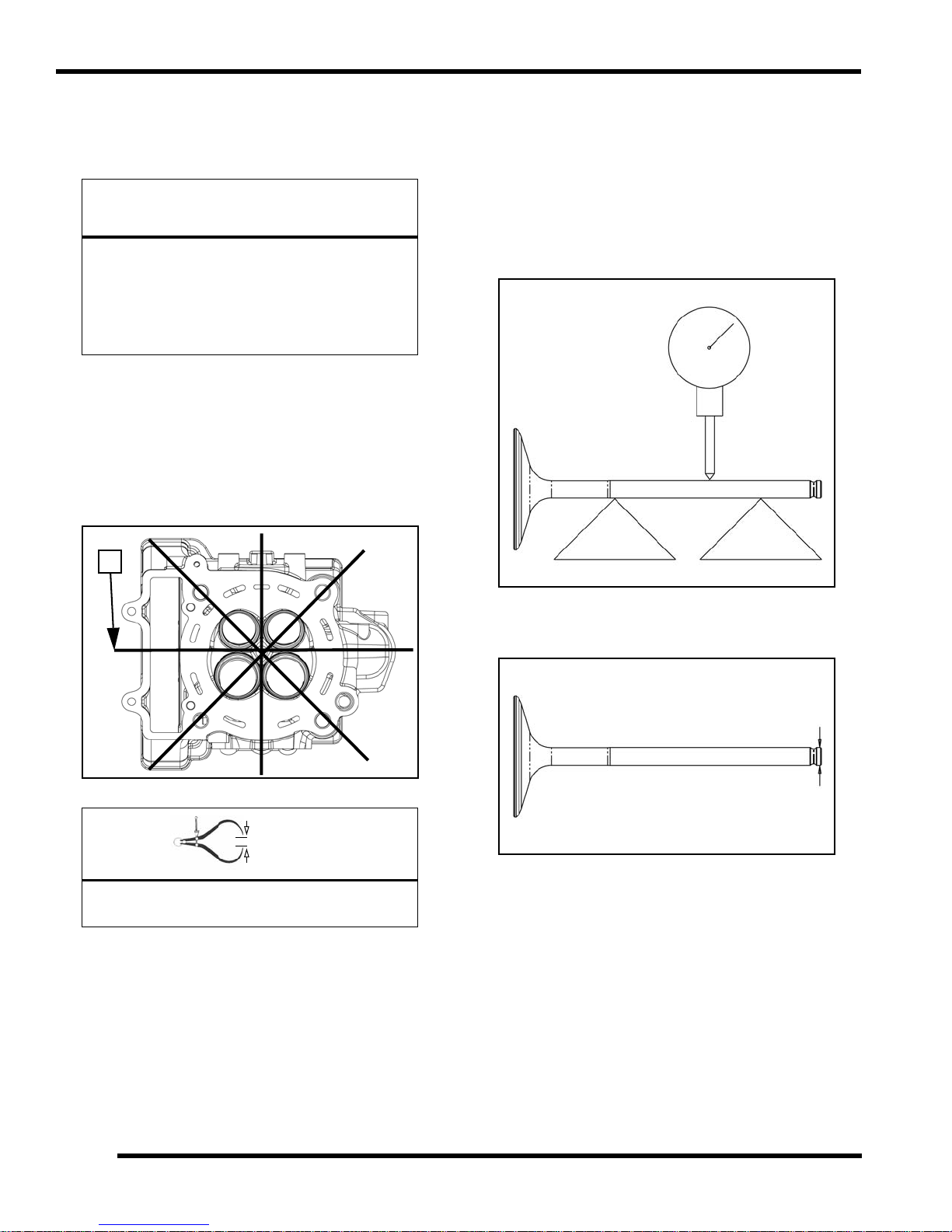
ENGINE / COOLING SYSTEM
CAUTION
= In. / mm.
E
Cylinder Head Inspection
Thoroughly clea n cylinde r h ead sur face to r emove a ll
traces of gasket material and carbon.
Use care not to damage gasket sealing surface.
All gasket surfaces must be clean, dry and free
of any oil or grease upon assembly. Clean
sealing surfaces with rubbing alcohol or
electrical contact cleaner. Do not touch sealing
surfaces of the new head gasket.
Cylinder Head Warp Inspection
1. Lay a s traight ed ge ( E) ac ross the s urface of th e
cylinder head at several different points and measure
warp by inserting a feeler gauge between the straight
edge and the cylinder head surface. If warp exceeds
the service limit, replace the cylinder head.
Valve Inspection
1. Remove all carbon from valves with a soft wire wheel
or brush.
2. Check va lve face for exce s
burnt spots.
3. To chec k for bent v alve st em
blocks and measure with a dial indicator.
sive runout, pit ting, a nd
s, mo unt va lve in “V ”
4. Check the end of the valve stem fo
wear or damage.
Cylinder Head Warp Limit:
.0024" (0.06 mm)
5. Inspect split keeper groove for wear or flaring in the
ke
eper seat area.
NOTE: The valves can be re-faced or end ground, if
essary. T hey mu st be re placed if e xtensively
nec
worn, burnt, bent or damaged.
r flaring, pitti ng,
3.44
9923523 - 2012 RANGER RZR 570 Service Manual
© Copyright 2011 Polaris Sales Inc.
Page 97

ENGINE / COOLING SYSTEM
= In. / mm.
= In. / mm.
WARNING
Combustion Area
6. Measure diameter of valve stem with a micrometer in
three places, then rotate 90° and measure again (take
six measurements total). Compare to specifications.
Valve Stem Diameter:
Intake: 0.2155" - 0.2161" (5.475 - 5.490 mm)
Exhaust: 0.2147" - 0.2153" (5.455 - 5.470 mm)
Combustion Chamber Cleaning
Wear eye protection during combustion
chamber cleaning.
1. Clean a ll accumulated car bon dep osits fro m
combustion chambers and valve seat area.
3
7. Measure valve guide inside dia
and end of the guide using a small hole gauge and a
micrometer. Measure in two directions.
Valve Guide I.D.:
0.2165" - 0.2171" (5.500 - 5.515 mm)
8. Be su re to mea sure each guide a nd valve
combination indiv
idually.
meter at the top middle
NOTE: Carbon Clean Fu el Tre atment (2 871326) ca n
e used to help remove carbon deposits.
b
IMPORTANT: Do not u se a met al scr aper, a co arse
brush or abrasive cleaners to clean the cylinder
wire
head. Damage may result.
2. Visually inspe ct cylinde r head g asket su rface and
bustion chamber for cracks or damage. Pay close
com
attention to th e ar eas a round sp ark p lug and valve
seats.
NOTE: The valve guides cannot be replaced.
3.45
9923523 - 2012 RANGER RZR 570 Service Manual
© Copyright 2011 Polaris Sales Inc.
Page 98

ENGINE / COOLING SYSTEM
WARNING
A
Valve Seat Reconditioning
Valve se at reconditioning should be pe rformed by a
technician pr oficient in cylinder hea d reco nditioning
techniques. Reconditioning techniques vary, so follow the
instructions pr ovided by the valve reco nditioning
equipment m anufacturer. D o not grind seats m ore than
necessary t o provide p roper seat su rface, w idth, and
contact point on valve face.
Wear eye protection or a face shield during
cylinder head disassembly and reassembly.
Valve Seat Inspection
Inspect valve seat in cylinder head for pitting, burnt spots,
oughness, a nd u neven sur face. If a ny of the a bove
r
conditions exist, the valve seat must be reconditioned. If
the valve seat is cracked the cylinder head must be
replaced.
Valve seat width and point of contact on the valve face is
y important for proper sealing. The valve must contact
ver
the valve seat over the entire circumference of the seat,
and the seat must be the proper width all the way around.
If the seat is uneven, compression leakage will result. If the
seat is too wide, seat pressure is reduced, causing carbon
accumulation and possible compression loss. If the seat is
too n arrow, he at tr ansfer fr om valve to seat is r educed.
The valve may over heat an d warp , r esulting in burnt
valves.
* If the contact area is less than 75% of the circumference
seat, rotate the pilot 180° and make another light cut.
of the
* If the cutter now contacts the uncut portion of the seat,
eck the pilot. Look for burrs, nicks, or runout. If the pilot
ch
is bent it must be replaced.
* If the contact area of the cutter is in the
valve guide is distorted from improper installation.
* If the contact area of the initial cut is greater than 75%,
c
ontinue to cut the seat until all pits are removed and a new
seat surface is evident.
NOTE: Remove on ly t he a mount o f material
essary to repair the seat surface.
nec
5. To check the contact area of the seat on the valve
ce, apply a thin coating of Prussian Blue paste to the
fa
valve seat. If using an interference angle (46°) apply
black p
6. Insert valve into guide and tap v
a few times.
ermanent marker to the entire valve face (A).
same place, the
alve lightly into place
Renewing Valve Seats
1. Install pilot into valve guide.
2. Apply cutting oil to valve seat and cutter.
3. Place 46° cutter on the pilot and make a light cut.
4. Inspect the cut area of the seat:
3.46
7. Remove valve an d check where the Pru ssian Blu e
indicate
seat should co ntact th e middle of th e valve face or
slightly above, and must be the proper width.
* If the indicated seat contact is at the
face and contacts the margin area (B) it is too high on the
valve face. Use the 30° cutter to lower the valve seat.
* If too lo w, use the 60° cutter to raise the se at. When
co
ntact area is centered on the valve face, measure seat
width.
* If the seat is too wide or uneven, use both top and bottom
tters to narrow the seat.
cu
* If the seat is too narrow, widen using the 45° cutter and
check contact point on the valve fa ce and seat width
reafter each cut.
9923523 - 2012 RANGER RZR 570 Service Manual
© Copyright 2011 Polaris Sales Inc.
s seat contact o n the valve face . The valve
top edge of the valve
Page 99

ENGINE / COOLING SYSTEM
B
A
Proper Seat Contact
on Valve Face
INTAKE
Seat Width
.039” (1.00 mm)
60°
45°
30°
= In. / mm.
EXHAUST
Seat Width
.059” (1.50 mm)
60°
45°
30°
NOTE: When us ing a n int erference a ngle, t he seat
contact point on the valve will be very narrow, and is
a normal condition. Look for an even and continuous
contact point all the way around the valve face (A).
Intake Seat Cutter Diameter: 1.567 in. (39.80 mm)
Exhaust Seat Cutter Diameter: 1.364 in. (34.65 mm)
3
Valve Seat Width:
Intake: .0393" (1.00 mm)
Service Limit: .0
Exhaust: .0
Service Limit: .0758" (1.9 mm)
8. Clean all filings from the area
Rinse and dry with compressed air.
9. Lubricate valve guides with clean engine oil and apply
il or water based lapping compound to the face of the
o
valve.
NOTE: Lapping is no t req uired if an interference
ngle reconditioning method is used.
a
10. Insert the valve into its respective guide and lap using
lapping tool or a section of fuel line connected to the
a
valve stem.
11. Rotate th e valve rapidly back and forth until the cut
unds smooth. Lift the valve slightly off of the seat,
so
rotate 1/4 turn, and repeat the lapping process. Do this
four to f ive times until t he valve is fully seated, and
repeat process for the other valves.
12. Thoroughly clean cylinder head and valves.
551" (1.4 mm)
590” (1.50 mm)
with hot s oapy water.
3.47
9923523 - 2012 RANGER RZR 570 Service Manual
© Copyright 2011 Polaris Sales Inc.
Page 100

ENGINE / COOLING SYSTEM
1/2” Down From Top of Cylinder
1/2” Up From Bottom
X
X
X
Y
Y
Y
Cylinder Removal
1. Remove and discard the head gasket.
2. Position the cam chain and guides vertically.
3. Tap cylin der lig htly with a p lastic h ammer in th e
reinforced areas only
4. Rock cylinder forward and backward and lift it from the
ankcase, supporting piston and connecting rod.
cr
5. Remove the cylinder from the engine.
until loose.
Cylinder Inspection
1. Remove all gasket material from the cylinder sealing
surfaces.
2. Inspect th e top of the cylin der for war page using a
ight edge and feeler gauge.
stra
Cylinder Warpage:
.00098” (.025 mm)
6. Remove and discard cylinder base gasket.
3. Inspect cylinder for wear, s
4. Inspect cylinder for ta per an d ou t o f r ound with a
te
lescoping gauge or a dial bore gauge. Measure in
two different directions, front to back and side to side,
on thr ee different levels (1 /2" down from top, in the
middle, and 1/2” up from bottom).
cratches, or damage.
3.48
9923523 - 2012 RANGER RZR 570 Service Manual
© Copyright 2011 Polaris Sales Inc.
 Loading...