

Page 1

POLARIS
RANGER
XP 700 4X4
RANGER 6X6
SERVICE
MANUAL
Page 2

GENERAL INFORMATION
1
MAINTENANCE
ENGINE
FUEL INJECTION
BODY / STEERING / SUSPENSION
CLUTCHING
2
3
4
5
6
FINAL DRIVE
TRANSMISSION
BRAKES
ELECTRICAL
7
8
9
10
Page 3

POLARIS
RANGER
XP 700 4X4
RANGER 6X6
SERVICE
MANUAL
Page 4

GENERAL INFORMATION
CHAPTER 1
GENERAL INFORMATION
MODEL INFORMATION . . . . . . . . . . . . . . . . . . . . . . . . . . . . . . . . . . . . . . . . . . . . . . . . . . 1.2
MODEL IDENTIFICATION . . . . . . . . . . . . . . . . . . . . . . . . . . . . . . . . . . . . . . . . . . . . . . . . 1.2
ENGINE DESIGNATION NUMBER . . . . . . . . . . . . . . . . . . . . . . . . . . . . . . . . . . . . . . . . . 1.2
VIN IDENTIFICATION . . . . . . . . . . . . . . . . . . . . . . . . . . . . . . . . . . . . . . . . . . . . . . . . . . . 1.2
ENGINE SERIAL NUMBER LOCATION . . . . . . . . . . . . . . . . . . . . . . . . . . . . . . . . . . . . . 1.2
UNIT SERIAL NUMBER (VIN) LOCATION . . . . . . . . . . . . . . . . . . . . . . . . . . . . . . . . . . . 1.3
TRANSMISSION I.D. NUMBER LOCATION . . . . . . . . . . . . . . . . . . . . . . . . . . . . . . . . . . 1.3
VEHICLE DIMENSIONS . . . . . . . . . . . . . . . . . . . . . . . . . . . . . . . . . . . . . . . . . . . . . . . . . . 1.4
VEHICLE DIMENSIONS RANGER 4X4, 6X6. . . . . . . . . . . . . . . . . . . . . . . . . . . . . . . . . . 1.5
GENERAL SPECIFICATIONS. . . . . . . . . . . . . . . . . . . . . . . . . . . . . . . . . . . . . . . . . . . . . . 1.6
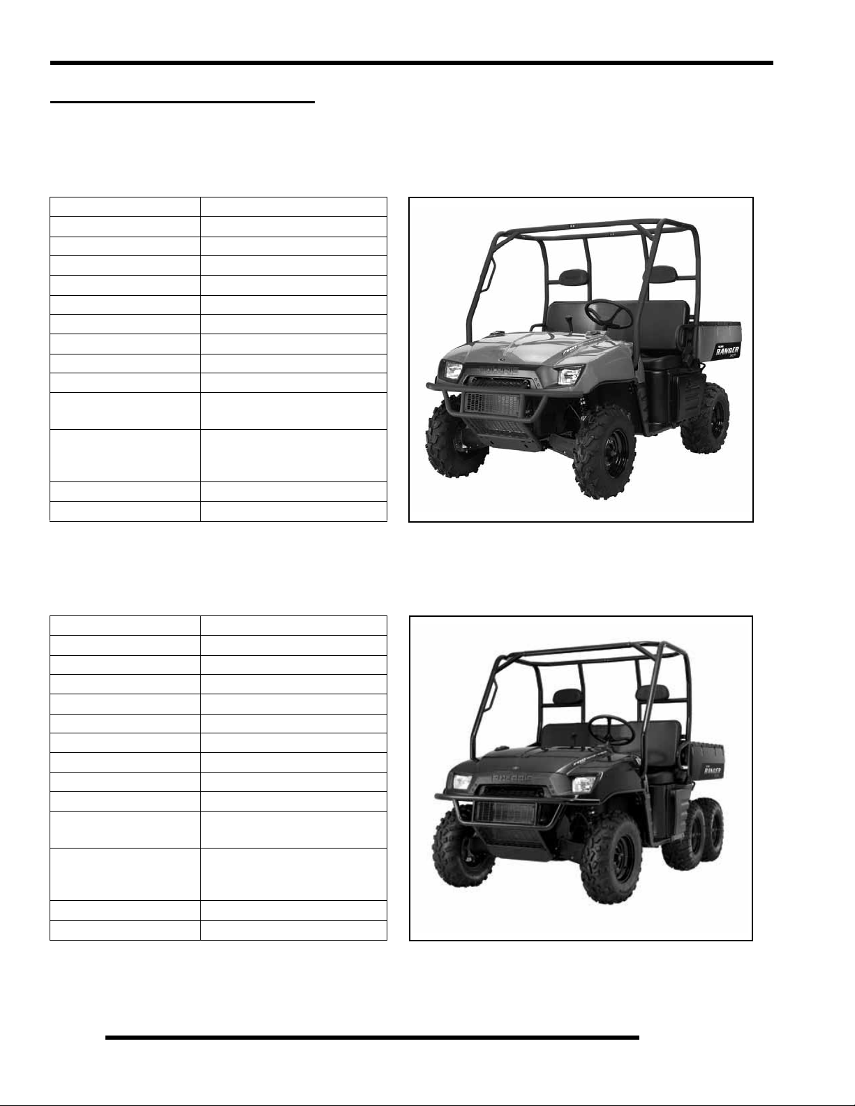
MODEL: RANGER XP 4X4 . . . . . . . . . . . . . . . . . . . . . . . . . . . . . . . . . . . . . . . . . . . 1.6
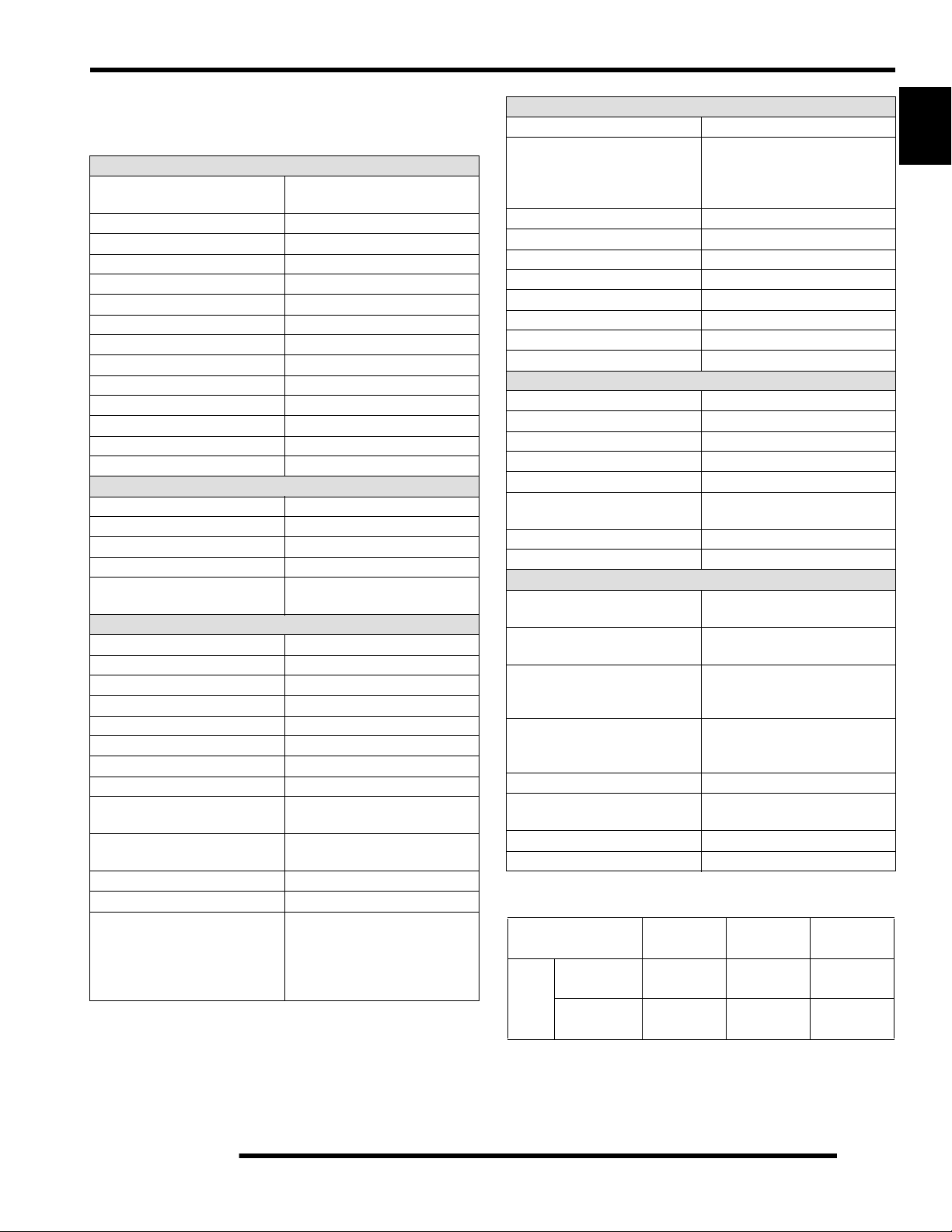
MODEL: RANGER XP 6X6 . . . . . . . . . . . . . . . . . . . . . . . . . . . . . . . . . . . . . . . . . . . 1.6
MODEL: RANGER XP 4X4 . . . . . . . . . . . . . . . . . . . . . . . . . . . . . . . . . . . . . . . . . . . 1.7
MODEL: RANGER XP 6X6 . . . . . . . . . . . . . . . . . . . . . . . . . . . . . . . . . . . . . . . . . . . 1.8
VEHICLE INFORMATION . . . . . . . . . . . . . . . . . . . . . . . . . . . . . . . . . . . . . . . . . . . . . . . . . 1.9
PUBLICATION NUMBERS. . . . . . . . . . . . . . . . . . . . . . . . . . . . . . . . . . . . . . . . . . . . . . . . 1.9
PAINT CODES . . . . . . . . . . . . . . . . . . . . . . . . . . . . . . . . . . . . . . . . . . . . . . . . . . . . . . . . . 1.9
REPLACEMENT KEYS . . . . . . . . . . . . . . . . . . . . . . . . . . . . . . . . . . . . . . . . . . . . . . . . . . 1.9
SPECIAL TOOLS . . . . . . . . . . . . . . . . . . . . . . . . . . . . . . . . . . . . . . . . . . . . . . . . . . . . . . . 1.9
MISC. SPECIFICATIONS AND CHARTS . . . . . . . . . . . . . . . . . . . . . . . . . . . . . . . . . . . . 1.10
CONVERSION TABLE . . . . . . . . . . . . . . . . . . . . . . . . . . . . . . . . . . . . . . . . . . . . . . . . . . 1.10
STANDARD TORQUE SPECIFICATIONS. . . . . . . . . . . . . . . . . . . . . . . . . . . . . . . . . . . 1.11
SAE TAP / DRILL SIZES . . . . . . . . . . . . . . . . . . . . . . . . . . . . . . . . . . . . . . . . . . . . . . . . 1.12
METRIC TAP / DRILL SIZES . . . . . . . . . . . . . . . . . . . . . . . . . . . . . . . . . . . . . . . . . . . . . 1.12
DECIMAL EQUIVALENTS . . . . . . . . . . . . . . . . . . . . . . . . . . . . . . . . . . . . . . . . . . . . . . . 1.12
GLOSSARY OF TERMS. . . . . . . . . . . . . . . . . . . . . . . . . . . . . . . . . . . . . . . . . . . . . . . . . 1.13
1
1.1
Page 5

GENERAL INFORMATION
MODEL INFORMATION
Model Identification
The machine model number must be used with any correspondence regarding warranty or service.
Machine Model Number Identification
R 0 7 R H 6 8 A G
Model Year
Designation
Engine Designation Number
EH068OLE043PLE............................................................Twin, Liquid Cooled, OHV 4 Stroke, Electric Start
VIN Identification
World
Mfg. ID
1 2 3 4 5 6 7 8 9 10 11 12 13 14 15 16 17
4 X A R H 6 8 A * 7 P 0 0 0 0 0 0
Vehicle Description
}
}
}
Basic Chassis
Designation
}
}
Emissions &
Model Option
Engine Designation
Vehicle Identifier
Body Style
Engine
Emissions
Powertrain
Engine Serial Number Location
Whenever corresponding about an engine, be sure to refer to the engine model number and serial number. This information can be
found on the sticker applied to the cylinder head on the side of engine.
Engine Serial Number
Model
Year
Check Digit
Plant No.
A
Individual Serial No.
* This could be either
a number or a letter
1.2
Page 6

GENERAL INFORMATION
Unit Serial Number (VIN) Location
The machine model number and serial number are important for
vehicle identification. The machine serial number (A) is
stamped on the lower LH frame rail close to the front drive
wheel. The model and serial number are also located on a sticker
under the hood (B).
A
Transmission I.D. Number Location
The transmission I.D. number is located on the
right side when installed in the machine.
1
B
A
A
1.3
Page 7

GENERAL INFORMATION
VEHICLE DIMENSIONS
RANGER 4X4, 6X6
75 in.
190.50 cm
10 in.
25.4 cm
RANGER 4x4
1.4
58 in.
147 cm
Page 8

V ehicle Dimensions RANGER 4X4, 6X6
GENERAL INFORMATION
120 in.
305 cm
90 in.
229 cm
1
58 in.
147 cm
27 in.
69 cm
113 in.
287 cm
76 in.
193 cm
58 in.
147 cm
1.5
Page 9
GENERAL INFORMATION
GENERAL SPECIFICATIONS
MODEL: RANGER XP 4X4
MODEL NUMBER: R07RH68AD,AG,AH,AK,AL,AW
ENGINE MODEL: EH068OLE
Category Dimension / Capacity
Length 113 in. / 287 cm
Width 60 in. / 152.4 cm
Height 75 in. / 190.5 cm
Wheel Base 76 in. / 193 cm
Ground Clearance 11.5 in. / (29 cm)
Turning Radius 132 in. / 335 cm
Dry Weight 1185 lbs. / 537 kg
Gross Vehicle Weight 2750 lbs. / 1247 kg
Cargo Box Capacity 1000 lbs. / 454 kg
Cargo Box Dimensions
Vehicle Payload
passengers - 500 lbs. / 227kg)
Hitch Towing Capacity 1500 lbs. / 681 kg
Hitch Tongue Capacity 150 lbs. / 68 kg
58 x 42 x 10 in.
(147 x 106.7 x 25.4 cm)
1500 lbs. / 681 kg
(Includes driver and two
MODEL: RANGER XP 6X6
MODEL NUMBER: R07RF68AF
ENGINE MODEL: EH068OLE
Category Dimension / Capacity
Length 120 in. / 305 cm
Width 60 in. / 152.4 cm
Height 75 in. / 190.5 cm
Wheel Base 90 in. / 229 cm
Ground Clearance 7.2 in. / (18.25 cm)
Turning Radius 180 in. / 457 cm
Dry Weight 1410 lbs. / 640 kg
Gross Vehicle Weight 2900 lbs. / 1315 kg
Cargo Box Capacity 1250 lbs. / 567 kg
Cargo Box Dimensions
Vehicle Payload
passengers - 500 lbs. / 227kg)
Hitch Towing Capacity 1750 lbs. / 794 kg
Hitch Tongue Capacity 150 lbs. / 68 kg
58 x 48 x 10 in.
(147 x 122 x 25.4 cm)
1750 lbs. / 794 kg
(Includes driver and two
1.6
Page 10
GENERAL INFORMATION
MODEL: RANGER XP 4X4
MODEL NUMBER: R07RH68AD,AG,AH,AK,AL,AW
ENGINE MODEL: EH068OLE
Engine
Platform
Engine Model Number EH068OLE044
Engine Displacement 683cc
Number of Cylinders 2
Bore & Stroke (mm) 80 x 68 mm
Compression Ratio 9.40:1
Compression Pressure 150-170 psi
Engine Idle Speed 1150 ± 100 RPM
Lubrication Pressurized Wet Sump
Oil Requirements 0W-40
Oil Capacity 2 qts. / 1.9 L
Coolant Capacity 3.25 qts. / 3.1 L
Overheat Warning Instrument Cluster Indicator
Exhaust System 2 to 1 Canister Style
Fuel System Type Bosch Electronic Fuel Injection
Fuel Delivery Electronic Fuel Pump (in tank)
Fuel Pressure 39 psi
Fuel Filters See Chapter 4
Fuel Capacity / Requirement
Alternator Max Output 500 watts @ 3000 RPM
Lights: Main Headlights 2 - Dual Beam 35 watts / quartz
Tail 5 watts x 2
Brake 5 watts x 2
Indicator Panel Lights 1 watt (ea.)
Starting System Electric Start
Ignition System Bosch EFI (ECU Controlled)
Ignition Timing 7° BTDC @ 1200 RPM
Spark plug / Gap
Battery / Model / Amp Hr
Instrument Type Multifunction Speedometer
DC Outlet Standard
Circuit Breakers
Polaris Domestic Twin Cylinder,
Liquid Cooled, 4-Stroke
Fuel System
9 gal. (34 l)
87 Octane (minimum)
Electrical
Champion RC7YC3 /
.035 in. (0.9 mm)
Yuasa YB30L-B /
30 Amp Hr. / 12 Volt
Fan: 20 Amp
Dash Harness: 20 Amp
Accessory Terminal: 20 Amp
Power Relay: 15 Amp
ECU Battery Supply: 6 Amp
Drivetrain
Transmission Type Polaris Automatic PVT
Gear Ratio: Front / Rear
High
Low
Rev
Drive Ratio - Front 3.818:1
Drive Ratio - Final 3.70:1
Shift Type In Line Shift - H / L / N / R
Trans. Oil Requirements Polaris AGL Gearcase Lube
Belt 3211106
Drive Belt Deflection 1.125” / 28.57 mm
Center Distance 10” / 254.5 mm
Clutch Offset 0.365” / 9.27 mm
Steering / Suspension
Front Suspension MacPherson Strut
Front Travel 8 in. / 20 cm
Rear Suspension Independent Rear Suspension
Rear Travel 9 in. / 23 cm
Ground Clearance 11.5 in. / 29 cm
Shock Preload Adjustment
Front / Rear
Turning Radius 132 in. / 335 cm
Toe Out 1/8-1/4 in. / 3-6.35 mm
Wheels / Brakes
Front Wheel Size
Rear Wheel Size
Front Tire
Make / Model / Size
Rear Tire
Make / Model / Size
F/R Tire Air Pressure 8-12 psi Front / 8-12 psi Rear
Brake - Front / Rear
Parking Brake Foot Actuated (Mechanica l)
Brake Fluid DOT 3 or DOT 4
L.E. Model AW - Kenda / Radial
L.E. Model AW - Kenda / Radial
3.34:1 / 2.89:1
8.67:1 / 7.49:1
5.92:1 / 5.11:1
Cam Adjustment
2-2” Twin Tubes
12 x 6 / 10 gauge
L.E. Model AW - 14 x 7
12 x 8 / 10 gauge
L.E. Model AW - 14 x 8
Carlisle / PXT / 26 x 8 R12
Bounty Hunter / 26 x 10 R14
Carlisle / PXT / 26 x 11 R12
Bounty Hunter / 26 x 12 R14
Foot Actuated - 4 Wheel
Hydraulic Disc
CLUTCH CHART
Altitude Shift Weight Drive Spring
Meters
(Feet)
0-1500
(0-5000)
1500-3700
(5000 - 12000)
20-60
(5631698)
20-56
(5631215)
Blu/Gray
(7042202)
Blu/Gray
(7042202)
1
Driven
Spring
Blk/Almd
(7043167)
Blk/Almd
(7043167)
1.7
Page 11

GENERAL INFORMATION
MODEL: RANGER XP 6X6
MODEL NUMBER: R07RF68AF
ENGINE MODEL: EH068OLE
Engine
Platform
Engine Model Number EH068OLE044
Engine Displacement 683cc
Number of Cylinders 2
Bore & Stroke (mm) 80 x 68 mm
Compression Ratio 9.40:1
Compression Pressure 150-170 psi
Engine Idle Speed 1150 ± 100 RPM
Lubrication Pressurized Wet Sump
Oil Requirements 0W-40
Oil Capacity 2 qts. / 1.9 L
Coolant Capacity 3.25 qts. / 3.1 L
Overheat Warning Instrument Cluster Indicator
Exhaust System 2 to 1 Canister Style
Fuel System Type Bosch Electronic Fuel Injection
Fuel Delivery Electronic Fuel Pump (in tank)
Fuel Pressure 39 psi
Fuel Filters See Chapter 4
Fuel Capacity / Requirement
Alternator Max Output 500 watts @ 3000 RPM
Lights: Main Headlights 2 - Dual Beam 35 watts / quartz
Tail 5 watts x 2
Brake 5 watts x 2
Indicator Panel Lights 1 watt (ea.)
Starting System Electric Start
Ignition System Bosch EFI (ECU Controlled)
Ignition Timing 7° BTDC @ 1200 RPM
Spark plug / Gap
Battery / Model / Amp Hr
Instrument Panel Type Multifunction Speedometer
DC Outlet Standard
Circuit Breakers
Polaris Domestic Twin Cylinder,
Liquid Cooled, 4-Stroke
Fuel System
9 gal. (34 l)
87 Octane (minimum)
Electrical
Champion RC7YC3 /
.035 in. (0.9 mm)
Yuasa YB30L-B /
30 Amp Hr. / 12 Volt
Fan: 20 Amp
Dash Harness: 20 Amp
Accessory Terminal: 20 Amp
Power Relay: 15 Amp
ECU Battery Supply: 6 Amp
Drivetrain
Transmission Type Polaris Automatic PVT
Gear Ratio: Front / Rear
High
Low
Rev
Drive Ratio - Front 3.818:1
Drive Ratio - Mid 3.70:1
Drive Ratio - Final 3.70:1
Shift Type In Line Shift - H / L / N / R
Trans. Oil Requirements Polaris AGL Gearcase Lube
Belt 3211106
Drive Belt Deflection 1.125” / 28.57 mm
Center Distance 10” / 254.5 mm
Clutch Offset 0.365” / 9.27 mm
Steering / Suspension
Front Suspension MacPherson Strut
Front Travel 8 in. / 20 cm
Center Suspension Progressive Rate / Independent
Center Travel 5.25 in. / 13 cm
Rear Suspension Swing Arm w/Dual Shocks
Rear Travel 6.25 in. / 16 cm
Ground Clearance 7.2 in. / 18.25 cm
Shock Preload Adjustment
Front / Rear
Turning Radius 180 in. / 457 cm
Toe Out 1/8-1/4 in. / 3-6.35 mm
Wheels / Brakes
Front Wheel Size 12 x 6 / 10 gauge
Middle / Rear Wheel Size 12 x 8 / 10 gauge
Front Tire
Make / Model / Size
Middle / Rear Tire
Make / Model / Size
F/M/R Tire Air Pressure 8-12 psi Front / 8-12 psi Rear
Brake - Front / Rear
Parking Brake Foot Actuated (Mechanical)
Brake Fluid DOT 3 or DOT 4
3.89:1 / 3.36:1
10.08:1 / 8.71:1
6.87:1 / 5.94:1
Cam Adjustment
2-2” Twin Tubes
Titan / AT489 / 25 x 10 R12
Titan / AT489 / 25 x 11 R12
Foot Actuated - 4 Wheel
Hydraulic Disc
CLUTCH CHART
Altitude Shift Weight Drive Spring
Meters
(Feet)
0-1500
(0-5000)
1500-3700
(5000 - 12000)
20-60
(5631698)
20-56
(5631215)
Blu/Gray
(7042202)
Blu/Gray
(7042202)
Driven
Spring
Blk/Almd
(7043167)
Blk/Almd
(7043167)
1.8
Page 12
V
P
M
20
20
NOTE:
NOTE:
www.purepolaris.com.
Paint Codes
RANGER XP 4x4 - Plastic - Hood / Dash Black Metallic P-177
RANGER XP 6x6 - Plastic - Hood / Dash Dark Green P-195
GENERAL INFORMATION
1
Painted Part Color Description Polaris Number
Frame / Cab Medium Gloss Black P-067
RANGER XP 4x4 - Plastic - Hood / Dash Turbo Silver P-402
RANGER XP 4x4 - Plastic - Hood / Dash
RANGER XP 4x4 - Plastic - Hood / Dash Delta Green P-492
RANGER XP 4x4 - Plastic - Hood / Dash Sunset Red Metallic P-520
Mossy Oak
™
P-455
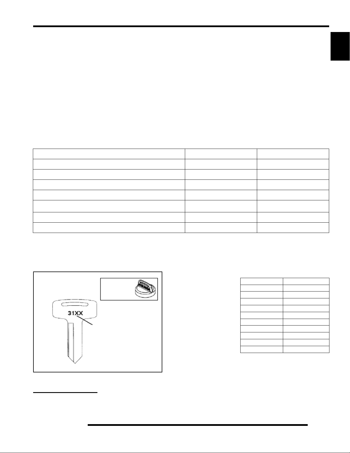
Replacement Keys
Replacement keys can be made from the original key. To identify which series the key is, take the first two digit s on th e original
key and refer to the chart to the right for the proper part number.
KEY COVER
P/N 5533534
Key Series
Number
Series# Part Number
20 4010278
21 4010278
22 4010321
23 4010321
27 4010321
28 4010321
31 4110141
32 4110148
67 4010278
68 4010278
SPECIAL TOOLS
Special tools may be required while servicing this vehicle. Some of the tools listed or depicted are mandatory, while other tools
maybe substituted with a similar tool, if available. Polaris recommends the use of Polaris Special Tools when servicing any Polaris
product. Dealers may order special tools through Polaris’ official tool supplier, SPX Corporation, 1-800-328-6657.
1.9
Page 13
GENERAL INFORMATION
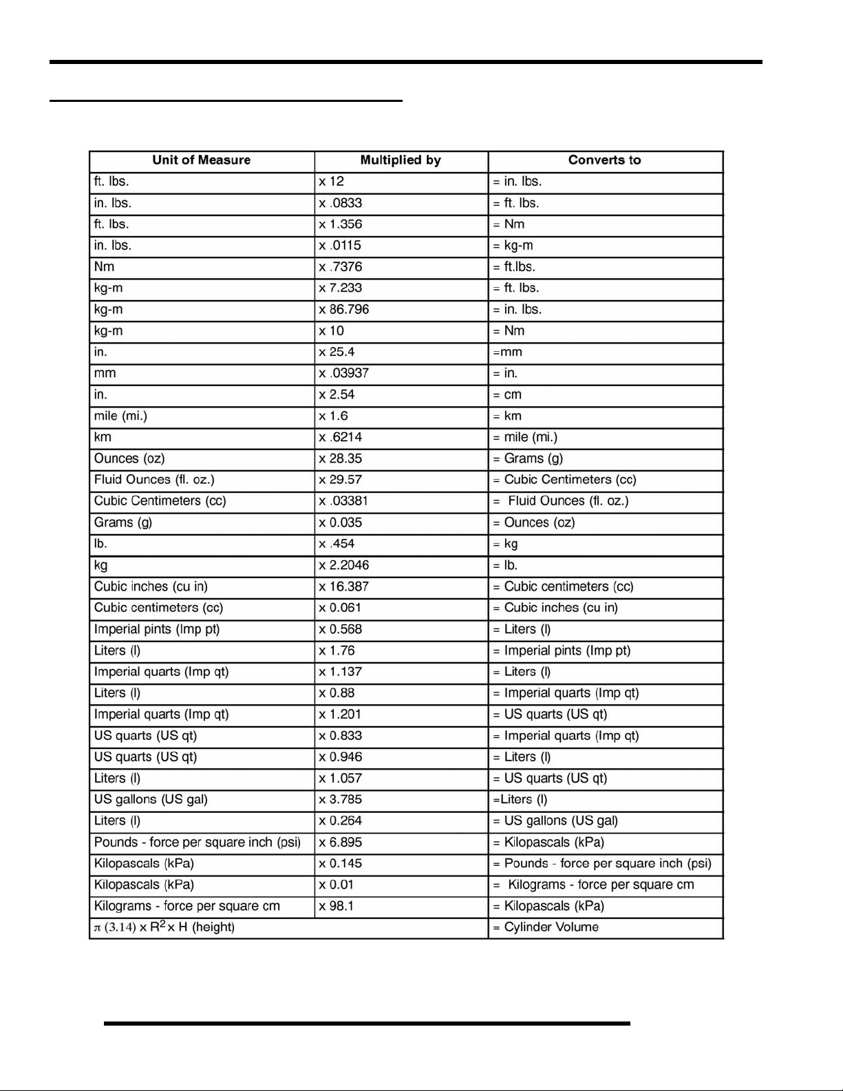
MISC. SPECIFICATIONS AND CHARTS
Conversion Table
1.10
°C to °F: 9 (°C + 40) ÷ 5 - 40 = °F °F to °C: (°F + 40) ÷ 9 - 40 = °C
Page 14

Standard Torque Specifications
GENERAL INFORMATION
The following torque specifications are to be used only as a general guideline. There are exceptions in the steering, suspension, and
engine areas. Always consult the exploded views or each manual section for torque values of fasteners before using standard torque.
1
1.11
Page 15

GENERAL INFORMATION
SAE Tap / Drill Sizes
Decimal Equivalents
Metric Tap / Drill Sizes
1.12
Page 16

GENERAL INFORMATION
Glossary of Terms
ABDC: After bottom dead center.
ACV: Alternating current voltage.
Alternator: Electrical generator producing voltage alternating current.
ATDC: After top dead center.
BBDC: Before bottom dead center.
BDC: Bottom dead center.
BTDC: Before top dead center.
CC: Cubic centimeters.
Center Distance: Distance between center of crankshaft and center of driven clutch shaft.
Chain Pitch: Distance between chain link pins (No. 35 = 3/8" or 1 cm). Polaris measures chain length in number of pitches.
CI: Cubic inches.
Clutch Buttons: Plastic bushings which aid rotation of the movable sheave in the drive and driven clutch.
Clutch Offset: Drive and driven clutches are offset so that drive belt will stay nearly straight as it moves along the clutch face.
Clutch Weights: Three levers in the drive clutch which relative to their weight, profile and engine RPM cause the drive clutch to
close and grip the drive belt.
Crankshaft Run-Out: Run-out or "bend" of crankshaft measured with a dial indicator while crankshaft is supported between centers
on V blocks or resting in crankcase. Measure at various points especially at PTO.
DCV: Direct current voltage
CVT: Centrifugal Variable Transmission (Drive Clutch System)
DCV: Direct current voltage.
Dial Bore Gauge: A cylinder measuring instrument which uses a dial indicator. Good for showing taper and out-of-round in the
cylinder bore.
Electrical Open: Open circuit. An electrical circuit which isn't complete.
Electrical Short: Short circuit. An electrical circuit which is completed before the current reaches the intended load. (i.e. a bare wire
touching the chassis).
End Seals: Rubber seals at each end of the crankshaft.
Engagement RPM: Engine RPM at which the drive clutch engages to make contact with the drive belt.
ft.: Foot/feet.
Foot Pound: Ft. lb. A force of one pound at the end of a lever one foot in length, applied in a rotational direction.
g: Gram. Unit of weight in the metric system.
gal.: Gallon.
ID: Inside diameter.
in.: Inch/inches.
Inch Pound: In. lb. 12 in. lbs. = 1 ft. lb.
kg/cm²: Kilograms per square centimeter.
kg-m: Kilogram meters.
Kilogram/meter: A force of one kilogram at the end of a lever one meter in length, applied in a rotational direction.
l or ltr: Liter.
lbs/in²: Pounds per square inch.
Left or Right Side: Always referred to based on normal operating position of the driver.
m: Meter/meters.
Mag: Magneto.
Magnetic Induction: As a conductor (coil) is moved through a magnetic field, a voltage will be generated in the windings.
Mechanical energy is converted to electrical energy in the stator.
mi.: Mile/miles.
mm: Millimeter. Unit of length in the metric system. 1 mm = approximately .040".
Nm: Newton meters.
OD: Outside diameter.
Ohm: The unit of electrical resistance opposing current flow.
oz.: Ounce/ounces.
Piston Clearance: Total distance between piston and cylinder wall.
psi.: Pounds per square inch.
PTO: Power take off.
PVT: Polaris Variable Transmission (Drive Clutch system)
qt.: Quart/quarts.
Regulator: Voltage regulator. Regulates battery charging system output at approx. 14.5 DCV as engine RPM increases.
Reservoir Tank: The fill tank in the liquid cooling system.
Resistance: In the mechanical sense, friction or load. In the electrical sense, ohms, resulting in energy conversion to heat.
RPM: Revolutions per minute.
Seized Piston: Galling of the sides of a piston. Usually there is a transfer of aluminum from the piston onto the cylinder wall.
Possible causes: 1) improper lubrication; 2) excessive temperatures; 3) insufficient piston clearance; 4) stuck piston rings.
Stator Plate: The plate mounted under the flywheel supporting the battery charging coils.
TDC: Top dead center. Piston's most outward travel from crankshaft.
Volt: The unit of measure for electrical pressure of electromotive force. Measured by a voltmeter in parallel with the circuit.
Watt: Unit of electrical power. Watts = amperes x volts.
WOT: Wide open throttle.
1
1.13
Page 17

GENERAL INFORMATION
CHAPTER 2
GENERAL INFORMATION
PERIODIC MAINTENANCE CHART. . . . . . . . . . . . . . . . . . . . . . . . . . . . . . . . . . . . . . . . . 2.3
PERIODIC MAINTENANCE OVERVIEW. . . . . . . . . . . . . . . . . . . . . . . . . . . . . . . . . . . . . 2.3
MAINTENANCE CHART KEY . . . . . . . . . . . . . . . . . . . . . . . . . . . . . . . . . . . . . . . . . . . . . 2.3
PRE-RIDE - 25 HOUR MAINTENANCE INTERVAL . . . . . . . . . . . . . . . . . . . . . . . . . . . . 2.4
50 - 100 HOUR MAINTENANCE INTERVAL . . . . . . . . . . . . . . . . . . . . . . . . . . . . . . . . . . 2.5
100 - 300 HOUR MAINTENANCE INTERVAL . . . . . . . . . . . . . . . . . . . . . . . . . . . . . . . . . 2.6
GENERAL COMPONENT LOCATIONS . . . . . . . . . . . . . . . . . . . . . . . . . . . . . . . . . . . . . . 2.7
RH SIDE AND DASH VIEW (4X4) . . . . . . . . . . . . . . . . . . . . . . . . . . . . . . . . . . . . . . . . . . 2.7
LH SIDE AND REAR VIEW (4X4) . . . . . . . . . . . . . . . . . . . . . . . . . . . . . . . . . . . . . . . . . . 2.8
LH SIDE AND RH SIDE VIEWS (6X6) . . . . . . . . . . . . . . . . . . . . . . . . . . . . . . . . . . . . . . . 2.9
SERVICE PRODUCTS AND LUBES. . . . . . . . . . . . . . . . . . . . . . . . . . . . . . . . . . . . . . . . 2.10
POLARIS LUBRICANTS, MAINTENANCE AND SERVICE PRODUCTS . . . . . . . . . . . 2.10
MAINTENANCE REFERENCES . . . . . . . . . . . . . . . . . . . . . . . . . . . . . . . . . . . . . . . . . . . 2.11
MAINTENANCE REFERENCES, CONTINUED. . . . . . . . . . . . . . . . . . . . . . . . . . . . . . . 2.12
GENERAL VEHICLE INSPECTION AND MAINTENANCE. . . . . . . . . . . . . . . . . . . . . . . 2.13
PRE-RIDE / DAILY INSPECTION . . . . . . . . . . . . . . . . . . . . . . . . . . . . . . . . . . . . . . . . . 2.13
FRAME, NUTS, BOLTS, AND FASTENERS . . . . . . . . . . . . . . . . . . . . . . . . . . . . . . . . . 2.13
SHIFT LINKAGE INSPECTION / ADJUSTMENT. . . . . . . . . . . . . . . . . . . . . . . . . . . . . . 2.13
FUEL SYSTEM AND AIR INTAKE . . . . . . . . . . . . . . . . . . . . . . . . . . . . . . . . . . . . . . . . . 2.14
FUEL SYSTEM. . . . . . . . . . . . . . . . . . . . . . . . . . . . . . . . . . . . . . . . . . . . . . . . . . . . . . . . 2.14
FUEL LINES . . . . . . . . . . . . . . . . . . . . . . . . . . . . . . . . . . . . . . . . . . . . . . . . . . . . . . . . . . 2.14
FUEL FILTER . . . . . . . . . . . . . . . . . . . . . . . . . . . . . . . . . . . . . . . . . . . . . . . . . . . . . . . . . 2.14
VENT LINES. . . . . . . . . . . . . . . . . . . . . . . . . . . . . . . . . . . . . . . . . . . . . . . . . . . . . . . . . . 2.14
THROTTLE PEDAL INSPECTION . . . . . . . . . . . . . . . . . . . . . . . . . . . . . . . . . . . . . . . . . 2.14
THROTTLE FREEPLAY ADJUSTMENT . . . . . . . . . . . . . . . . . . . . . . . . . . . . . . . . . . . . 2.15
AIR FILTER SERVICE . . . . . . . . . . . . . . . . . . . . . . . . . . . . . . . . . . . . . . . . . . . . . . . . . . 2.15
AIR INTAKE INSPECTION. . . . . . . . . . . . . . . . . . . . . . . . . . . . . . . . . . . . . . . . . . . . . . . 2.16
ENGINE . . . . . . . . . . . . . . . . . . . . . . . . . . . . . . . . . . . . . . . . . . . . . . . . . . . . . . . . . . . . . . 2.17
COMPRESSION AND LEAKDOWN TEST. . . . . . . . . . . . . . . . . . . . . . . . . . . . . . . . . . . 2.17
BREATHER HOSE INSPECTION . . . . . . . . . . . . . . . . . . . . . . . . . . . . . . . . . . . . . . . . . 2.17
ENGINE OIL LEVEL . . . . . . . . . . . . . . . . . . . . . . . . . . . . . . . . . . . . . . . . . . . . . . . . . . . . 2.17
ENGINE OIL AND FILTER CHANGE. . . . . . . . . . . . . . . . . . . . . . . . . . . . . . . . . . . . . . . 2.18
EXHAUST PIPE . . . . . . . . . . . . . . . . . . . . . . . . . . . . . . . . . . . . . . . . . . . . . . . . . . . . . . . 2.19
TRANSMISSION AND GEARCASES . . . . . . . . . . . . . . . . . . . . . . . . . . . . . . . . . . . . . . . 2.20
TRANSMISSION LUBRICATION . . . . . . . . . . . . . . . . . . . . . . . . . . . . . . . . . . . . . . . . . 2.20
FRONT GEARCASE LUBRICATION (4X4) . . . . . . . . . . . . . . . . . . . . . . . . . . . . . . . . . . 2.21
MIDDLE GEARCASE LUBRICATION (6X6) . . . . . . . . . . . . . . . . . . . . . . . . . . . . . . . . . 2.22
REAR GEARCASE LUBRICATION (4X4) . . . . . . . . . . . . . . . . . . . . . . . . . . . . . . . . . . . 2.23
REAR GEARCASE LUBRICATION (6X6) . . . . . . . . . . . . . . . . . . . . . . . . . . . . . . . . . . . 2.24
COOLING SYSTEM. . . . . . . . . . . . . . . . . . . . . . . . . . . . . . . . . . . . . . . . . . . . . . . . . . . . . 2.25
LIQUID COOLING SYSTEM OVERVIEW . . . . . . . . . . . . . . . . . . . . . . . . . . . . . . . . . . . 2.25
COOLANT LEVEL INSPECTION . . . . . . . . . . . . . . . . . . . . . . . . . . . . . . . . . . . . . . . . . . 2.25
RADIATOR COOLANT LEVEL INSPECTION . . . . . . . . . . . . . . . . . . . . . . . . . . . . . . . . 2.26
COOLANT STRENGTH / TYPE . . . . . . . . . . . . . . . . . . . . . . . . . . . . . . . . . . . . . . . . . . . 2.26
COOLING SYSTEM PRESSURE TEST. . . . . . . . . . . . . . . . . . . . . . . . . . . . . . . . . . . . . 2.26
COOLING SYSTEM HOSES . . . . . . . . . . . . . . . . . . . . . . . . . . . . . . . . . . . . . . . . . . . . . 2.26
RADIATOR . . . . . . . . . . . . . . . . . . . . . . . . . . . . . . . . . . . . . . . . . . . . . . . . . . . . . . . . . . . 2.27
COOLANT DRAIN / RADIATOR REMOVAL . . . . . . . . . . . . . . . . . . . . . . . . . . . . . . . . . 2.27
2
2.1
Page 18

GENERAL INFORMATION
FINAL DRIVE / WHEEL AND TIRE . . . . . . . . . . . . . . . . . . . . . . . . . . . . . . . . . . . . . . . . . 2.27
WHEEL, HUB, AND SPINDLE TORQUE TABLE. . . . . . . . . . . . . . . . . . . . . . . . . . . . . . 2.27
CV SHAFT BOOT INSPECTION . . . . . . . . . . . . . . . . . . . . . . . . . . . . . . . . . . . . . . . . . . 2.28
WHEEL REMOVAL . . . . . . . . . . . . . . . . . . . . . . . . . . . . . . . . . . . . . . . . . . . . . . . . . . . . 2.28
WHEEL INSTALLATION . . . . . . . . . . . . . . . . . . . . . . . . . . . . . . . . . . . . . . . . . . . . . . . . 2.28
TIRE INSPECTION. . . . . . . . . . . . . . . . . . . . . . . . . . . . . . . . . . . . . . . . . . . . . . . . . . . . . 2.28
TIRE PRESSURE. . . . . . . . . . . . . . . . . . . . . . . . . . . . . . . . . . . . . . . . . . . . . . . . . . . . . . 2.29
ELECTRICAL AND IGNITION SYSTEM . . . . . . . . . . . . . . . . . . . . . . . . . . . . . . . . . . . . . 2.29
BATTERY MAINTENANCE . . . . . . . . . . . . . . . . . . . . . . . . . . . . . . . . . . . . . . . . . . . . . . 2.29
BATTERY FLUID LEVEL (CONVENTIONAL BATTERY) . . . . . . . . . . . . . . . . . . . . . . . 2.29
BATTERY REMOVAL. . . . . . . . . . . . . . . . . . . . . . . . . . . . . . . . . . . . . . . . . . . . . . . . . . . 2.29
BATTERY INSTALLATION. . . . . . . . . . . . . . . . . . . . . . . . . . . . . . . . . . . . . . . . . . . . . . . 2.30
BATTERY STORAGE. . . . . . . . . . . . . . . . . . . . . . . . . . . . . . . . . . . . . . . . . . . . . . . . . . . 2.30
BATTERY CHARGING. . . . . . . . . . . . . . . . . . . . . . . . . . . . . . . . . . . . . . . . . . . . . . . . . . 2.30
SPARK PLUG SERVICE . . . . . . . . . . . . . . . . . . . . . . . . . . . . . . . . . . . . . . . . . . . . . . . . 2.30
ENGINE TO FRAME GROUND . . . . . . . . . . . . . . . . . . . . . . . . . . . . . . . . . . . . . . . . . . . 2.31
STEERING AND SUSPENSION . . . . . . . . . . . . . . . . . . . . . . . . . . . . . . . . . . . . . . . . . . . 2.31
STEERING . . . . . . . . . . . . . . . . . . . . . . . . . . . . . . . . . . . . . . . . . . . . . . . . . . . . . . . . . . . 2.31
TIE ROD END / STEERING INSPECTION . . . . . . . . . . . . . . . . . . . . . . . . . . . . . . . . . . 2.31
CAMBER AND CASTER . . . . . . . . . . . . . . . . . . . . . . . . . . . . . . . . . . . . . . . . . . . . . . . . 2.31
WHEEL TOE ALIGNMENT INSPECTION . . . . . . . . . . . . . . . . . . . . . . . . . . . . . . . . . . . 2.32
TOE ADJUSTMENT . . . . . . . . . . . . . . . . . . . . . . . . . . . . . . . . . . . . . . . . . . . . . . . . . . . . 2.32
FRONT SUSPENSION. . . . . . . . . . . . . . . . . . . . . . . . . . . . . . . . . . . . . . . . . . . . . . . . . . 2.33
REAR SUSPENSION . . . . . . . . . . . . . . . . . . . . . . . . . . . . . . . . . . . . . . . . . . . . . . . . . . . 2.33
REAR SUSPENSION ADJUSTMENT (4X4) . . . . . . . . . . . . . . . . . . . . . . . . . . . . . . . . . 2.33
REAR SPRING ADJUSTMENT . . . . . . . . . . . . . . . . . . . . . . . . . . . . . . . . . . . . . . . . . . . 2.34
BRAKE SYSTEM. . . . . . . . . . . . . . . . . . . . . . . . . . . . . . . . . . . . . . . . . . . . . . . . . . . . . . . 2.34
BRAKE SYSTEM INSPECTION. . . . . . . . . . . . . . . . . . . . . . . . . . . . . . . . . . . . . . . . . . . 2.34
BRAKE PAD INSPECTION . . . . . . . . . . . . . . . . . . . . . . . . . . . . . . . . . . . . . . . . . . . . . . 2.34
PARKING BRAKE PAD INSPECTION . . . . . . . . . . . . . . . . . . . . . . . . . . . . . . . . . . . . . . 2.35
BRAKE HOSE AND FITTING INSPECTION . . . . . . . . . . . . . . . . . . . . . . . . . . . . . . . . . 2.35
2.2
Page 19

GENERAL INFORMATION
PERIODIC MAINTENANCE CHART
Periodic Maintenance Overview
Careful periodic maintenance will help keep your vehicle in the safest, most reliable condition. Inspection, adjustment
and lubrication of important components are explained in the periodic maintenance chart.
Inspect, clean, lubricate, adjust and replace parts as necessary. When inspection reveals the need for replacement
parts, use genuine Polaris parts available from your Polaris dealer.
NOTE: Service and adjustments are critical. If you’re not familiar with safe service and adjustment
procedures, have a qualified dealer perform these operations.
Maintenance intervals in the following chart are based upon average riding conditions and an average vehicle speed of
approximately 10 miles per hour. Vehicles subjected to severe use must be inspected and serviced more frequently.
Severe Use Definition
• Frequent immersion in mud, water or sand
• Racing or race-style high RPM use
• Prolonged low speed, heavy load operation
• Extended idle
2
• Short trip cold weather operation
Pay special attention to the oil level. A rise in oil level during cold weather can indicate contaminants collecting in the
oil sump or crankcase. Change oil immediately if the oil level begins to rise. Monitor the oil level, and if it continues to
rise, discontinue use and determine the cause or see your dealer.
Maintenance Chart Key
The following symbols denote potential items to be aware of during maintenance :
= CAUTION: Due to the nature of these adjustments, it is recommended this service be performed by an
authorized Polaris dealer.
= SEVERE USE ITEM --If vehicle is subjected to severe use, decrease interval by 50%
(Severe Use is defined as frequent vehicle immersion in mud, water or sand, racing or race-style high rpm
use, prolonged low speed - heavy load operation or exte nde d idle. More pre ven tati ve maint enance is r equire d
under these conditions. Fluid changes, cable, chain and chassis lu bricat i on are re quired more fre quently. For
engine oil, short trip cold weather riding also constitutes se vere use. Pay specia l attention to oil lev el. A rising
oil level in cold weather can indicate contaminants collecting in the oil sump or crankcase. Change oil immediately and monitor level. If oil level begins to rise, discontinue use and determine cause.)
E= Emission Control System Service (California).
NOTE: Inspection may reveal the need for replacement parts. Always use genuine Polaris parts.
WARNING
Improperly performing the procedures marked with a could
result in component failure and lead to serious injury or death.
Have an authorized Polaris dealer perform these services.
2.3
Page 20

GENERAL INFORMATION
Pre-Ride - 25 Hour Maintenance Interval
Maintenance Interval
Item
Hours Calendar
Steering - Pre-Ride -
Front Suspension - Pre-Ride -
Rear Suspension - Pre-Ride -
Tires - Pre-Ride -
Brake Fluid Level - Pre-Ride -
Brake Pedal Travel - Pre-Ride -
Brake Systems - Pre-Ride Wheels / Fasteners - Pre-Ride Frame Fasteners - Pre-Ride -
Engine Oil Level - Pre-Ride -
E
Air Filter / Pre-Filter - Daily - Inspect;clean often
E
Air Box Sediment Tube - Daily - Drain deposits when visible
E
Coolant Level - Daily -
Head Lamp / Tail Lamp - Daily -
Air Filter,
Main Element
E
Brake Pad Wear / Inspect
Parking Brake Pads
Battery 20 H Monthly - Check terminals; clean; test
Front Gearcase Oil
(if equipped)
Middle Gearcase Oil
(if equipped)
Rear Gearcase Oil
(if equipped)
Transmission Oil 25 H Monthly - Inspect level; change yearly
Engine Breather
Filter (if equipped)
E
Engine Oil Change
(Break-In Period)
E
10 H Monthly - Inspect periodically
25 H Monthly - Inspect level; change yearly
25 H Monthly - Inspect level; change yearly
25 H Monthly - Inspect level; change yearly
25 H Monthly - Inspect; replace if necessary
25 H 1 M - Perform a break-in oil change at one month
(whichever comes first)
Miles
(KM)
Make adjustments as needed.
See Pre-Ride Checklist on Page 2.13.
Check level daily, change coolant every 2
years
Check operation; apply dielectric grease if
replacing
- Weekly - Inspect; replace as needed
Remarks
Perform these procedures more often for vehicles subjected to severe use.
E Emission Control System Service (California)
Have an authorized Polaris dealer perform these services.
2.4
Page 21
GENERAL INFORMATION
50 - 100 Hour Maintenance Interval
Maintenance Interval
Item
General Lubrication 50 H 3 M -
Shift Linkage 50 H 6 M - Inspect, lubricate, adjust
Steering 50 H 6 M - Lubricate
Front Suspension 50 H 6 M - Lubricate
Rear Suspension 50 H 6 M - Lubricate
EThrottle Cable / Throttle
Pedal
Throttle Body Air Intake
E
Ducts / Flange
Drive Belt 50 H 6 M - Inspect; adjust; replace as needed
Cooling System 50 H 6 M -
Engine Oil Change 100 H 6 M -
E
Oil Filter Change 100 H 6 M - Replace with oil change
E
(whichever comes first)
Hours Calendar
50 H 6 M -
50 H 6 M - Inspect ducts for proper sealing/air leaks
Miles
(KM)
Lubricate all grease fittings, pivots, cables,
etc.
Inspect; adjust; lubricate; replace if
necessary
Inspect coolant strength seasonally;
pressure test system yearly
Perform a break-in oil change at 25 hours/
one month
Remarks
2
Perform these procedures more often for vehicles subjected to severe use.
E Emission Control System Service (California)
Have an authorized Polaris dealer perform these services.
2.5
Page 22

GENERAL INFORMATION
100 - 300 Hour Maintenance Interval
Maintenance Interval
Item
Hours Calendar
Fuel System 100 H 12M -
E
Fuel Filter 100 H 12M - Replace yearly
E
Radiator 100 H 12M - Inspect; clean external surfaces
Cooling Hoses 100 H 12M - Inspect for leaks
Engine Mounts 100 H 12M - Inspect
Exhaust Muffler / Pipe 100 H 12M - Inspect
Spark Plug 100 H 12M - Inspect; replace as needed
E
Wiring 100 H 12M -
Clutches (Drive and Driven) 100 H 12M - Inspect;clean; replace worn parts
Front Wheel Bearings 100 H 12M - Inspect; replace as needed
Toe Adjustment 100 H
Brake Fluid 200 H 24M - Change every two years (DOT 3 or DOT 4)
Spark Arrestor 300 H 36M - Clean out
Auxiliary Brake - Inspect daily; adjust as needed
Headlight Aim - Adjust as needed
(whichever comes first)
Miles
(Km)
Remarks
Check for leaks at tank cap, fuel lines, fuel
pump, and fuel rail.
Replace lines every two years.
Inspect for wear, routing, security; apply
dielectric grease to connectors subjected to
water, mud, etc.
Inspect periodically; adjust when parts are
replaced
Perform these procedures more often for vehicles subjected to severe use.
E Emission Control System Service (California)
Have an authorized Polaris dealer perform these services.
2.6
Page 23
GENERAL COMPONENT LOCATIONS
RH Side (4X4) and Dash View
Gas Tank
Rear Gearcase
GENERAL INFORMATION
2
Front Gearcase
(Behind Radiator)
Cup
Holder
Storage
Box
Engine (under seat)
Dash Components
Instrument
Cluster
Ignition
Switch
Storage
Tray
Light
Switch
Mode
Button
AWD / Differential Switch
(if equipped)
12V
Accessory
Outlet
Storage
Compartment
(with lid)
Cup
Holder
2.7
Page 24

GENERAL INFORMATION
LH Side and Rear View (4X4)
Battery
Front Prop Shaft
Tail Gate Latch
Air Cleaner
Storage
Compartment
Rear Prop Shaft
Transmission
2.8
2" Hitch
Muffler
Drive Shafts
Page 25

LH Side and RH Side Views (6X6)
GENERAL INFORMATION
2
Front Gearcase
(behind radiator)
Rear Gearcase
Battery
Engine (under seat)
Transmission
Mid Gearcase
Front Prop Shaft
Drive Shafts
Rear Prop Shaft
2.9
Page 26

GENERAL INFORMATION
SERVICE PRODUCTS AND LUBES
Polaris Lubricants, Maintenance and Service
Products
Part No. Description
Engine Lubricant
2870791 Fogging Oil (12 oz. Aerosol)
2871098
2871281
2871844
2871567
2873602
2873603
2871653
2872276
2870465 Oil Pump for 1 Gallon Jug
2871654
2872277
2871322
2871423
2871460 Starter Drive Grease (12 Count)
2871515 Premium U-Joint Lube (3 oz.) (24 Count)
2871551 Premium U-Joint Lube (14 oz.) (10 Count)
2871312 Grease Gun Kit
2871329 Dielectric Grease (Nyogel™)
2871323 60/40 Coolant (Gallon) (6 Count)
2871534 60/40 Coolant (Quart) (12 Count)
Premium 2 Cycle Engine Oil (Quart) (12
Count)
Engine Oil (Quart) Premium 4 Synthetic
0W-40 (4-Cycle) (12 Count)
Engine Oil (Gallon) Premium 4 Synthetic
0W-40 (4-Cycle) (4 Count)
Engine Oil (16 Gallon) Premium 4
Synthetic 0W-40 (4-Cycle)
Gearcase / Transmission Lubricants
Premium Synthetic AGL Gearcase Lube
(12 oz. bottle) (12 Count)
Premium Synthetic AGL Gearcase Lube
(1 Gal.) (4 Count)
Premium ATV Angle Drive Fluid
(8 oz.) (12 Count)
Premium ATV Angle Drive Fluid
(2.5 Gal) (2 Count)
Premium Demand Drive Hub Fluid
(8 oz.) (12 Count)
Premium Demand Drive Hub Fluid
(2.5 gal.) (2 Count)
Grease / Specialized Lubricants
Premium All Season Grease
(3 oz. cartridge) (24 Count)
Premium All Season Grease
(14 oz. cartridge) (10 Count)
Coolant
NOTE: Each item can be purchased separately at
your local Polaris dealer.
Part No. Description
Additives / Sealants / Thread Locking Ag ents / Misc.
2870585 Loctite™ Primer N, Aerosol, 25 g
2871956
2871949
2871950
2871951
2871952
2871953
2871954
2870584
2870587
2871326
2870652 Fuel Stabilizer (16 oz.) (12 Count)
2871957
2871958
2870990 DOT 3 Brake Fluid (12 Count)
2871557 Crankcase Sealant, 3-Bond 1215 (5oz.)
2872893 Engine Degreaser (12oz.) (12 Count)
NOTE: The number count indicated by each part
number in the table above indicates the number of
units that are shipped with each order.
Loctite™ Thread Sealant 565
(50 ml.) (6 Count)
Loctite™ Threadlock 242
(50 ml.) (10 Count)
Loctite™ Threadlock 242
(6 ml.) (12 Count)
Loctite™ Threadlock 262
(50 ml.) (10 Count)
Loctite™ Threadlock 262
(6 ml.) (12 Count)
Loctite™ Threadlock 271
(6 ml.) (12 Count)
Loctite™ Threadlock 271
(36 ml.) (6 Count)
Loctite™ 680-Retaining Compound
(10 ml.)
Loctite™ 518 Gasket Eliminator / Flange
Sealant (50 ml.) (10 Count)
Premium Carbon Clean
(12 oz.) (12 Count)
Black RTV Silicone Sealer
(3 oz. tube) (12 Count)
Black RTV Silicone Sealer
(11 oz. cartridge) (12 Count)
2.10
Page 27

GENERAL INFORMATION
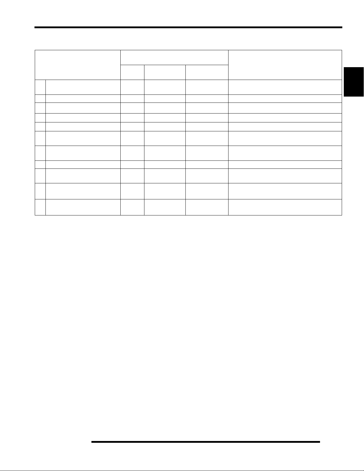
MAINTENANCE REFERENCES
Item Lube Rec. Method Frequency*
Change after 1st month (25 hrs), 6 months
1. Engine Oil
2. Brake Fluid DOT 3 (PN 2870990) or Dot 4
3. Transmission
4. Front Gearcase
5. Middle Gearcase
* More often under severe use, such as operated in water or under severe loads.
**Semi-annually or 50 hours of operation (refer to Maintenance Schedule for additional information)
***Annually or 100 hours of operation (refer to Maintenance Schedule for additional information)
Polaris 0W-40
Synthetic (PN 2871281)
Polaris AGL Gearcase
Lubricant (PN 2873602)
Polaris Demand Drive Hub
Fluid (PN 2871654)
ATV Angle Drive Fluid
(PN 2871653)
Add oil to proper level.
Fill reservoir between MAX
and Min lines.
Add lube to bottom of fill plug
threads.
Drain completely. Add lube to
specified quantity.
Drain completely. Add lube to
specified quantity.
or 100 hours thereafter; Change more often
in extremely dirty conditions, or short trip
cold weather operation.
As required. Change fluid every 2 years.
Change annually. Change more often if
used in severe conditions.
Change annually***
Semi-annually**
2
1. Engine
Dipstick / Fill Tube
4. Front Gearcase
2. Brake Master Cylinder
3. Transmission
5. Middle Gearcase (6x6)
Drain Plug
Fill Plug
Fill Plug
Drain Plug
2.11
Page 28
GENERAL INFORMATION
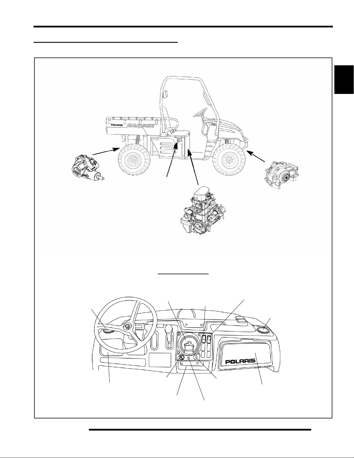
Maintenance References, Continued.....
Item Lube Rec. Method Frequency*
Locate grease fitting on the
6. Hubstrut Assembly
(Both Sides)
7. Swing Arm Pivot
8. Rear Prop Shaft Yoke
9. Front Prop Shaft Yoke
10. Rear Gearcase
* More often under severe use, such as operated in water or under severe loads.
**Semi-annually or 50 hours of operation (refer to Maintenance Schedule for additional information)
***Annually or 100 hours of operation (refer to Maintenance Schedule for additional information)
Grease conforming to NLGI No. 2, such as Polaris Premium All Season Grease, Conoco Superlube M or Mobilegrease Special
Polaris All Season Grease (PN
2871423)
Polaris All Season Grease (PN
2871423)
Polaris Premium U-Joint Lube
(PN 2871551)
Polaris Premium U-Joint Lube
(PN 2871551)
ATV Angle Drive Fluid
(PN 2871653)
underside of the hubstrut
assembly and grease with
grease gun.
Locate grease fitting on inside
of the swing arm pivot.
Locate fittings and grease with
grease gun.
Locate fittings and grease with
grease gun.
Drain completely. Add lube to
specified quantity.
Semi-annually**
Semi-annually**
Semi-annually**
Semi-annually**
Change annually***
6. Hubstrut Assembly
Swing Arm Pivot
7. Swing Arm (6x6)
9. Front Prop Shaft
10. Rear Gearcase
(6x6)
8. Rear Prop Shaft (6x6)
10. Rear Gearcase
Fill Plug
Yoke
Yoke
(4x4)
2.12
Page 29

GENERAL INFORMATION
GENERAL VEHICLE INSPECTION
AND MAINTENANCE
Pre-Ride / Daily Inspection
Perform the following pre-ride inspection daily, and when
servicing the vehicle at each scheduled maintenance.
• Tires - check condition and pressures
• Fuel and oil tanks - fi ll both tanks to their proper level;
Do not overfill oil tank
• All brakes - check operation and adjustment (includ es
auxiliary brake)
• Throttle - check for free operation and closing
• Headlight/Taillight/Brakelight - check operation of all
indicator lights and switches
• Engine stop switch - check for proper function
• Wheels - check for tightness of wheel nuts and axle
nuts; check to be sure axle nuts are secured by cotter
pins
Shift Linkage Inspection / Adjustment
Linkage rod adjustment is necessary when symptoms include:
• No All Wheel Drive light
• Noise on deceleration
• Inability to engage a gear
• Excessive gear clash (noise)
• Shift selectors moving out of desired range
NOTE: Remove necessary components to gain
access to shift linkage cable ends (i.e. exhaust heat
shield, exhaust pipe, etc.)
2
• Air cleaner element - check for dirt; clean or replace
• Steering - check for free operation noting any unusual
looseness in any area
• Loose parts - visually inspect vehicle fo r any damaged
or loose nuts, bolts or fasteners
• Engine coolant - check for proper level at the recovery
bottle
• Check all rear suspension components for wear or
damage.
Frame, Nuts, Bolts, and Fasteners
Periodically inspect the torque of all fasteners in accordance
with the maintenance schedule. Check that all cotter pins are in
place. Refer to specific fastener torques listed in each chapter.
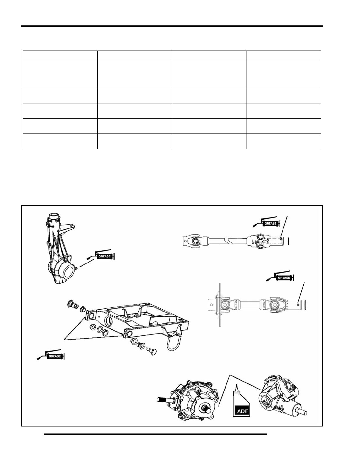
1. Inspect shift linkage cable, clevis pins, and pivot bushings
and replace if worn or damaged.
2. Be sure idle speed is adjusted properly.
3. Place gear selector in neutral. Make sure the transmission
bell crank is engaged in the neutral position detents.
4. With two wrenches loosen the outside jam nut
counterclockwise. Turn the outside jam nut 1 1/2 turns.
Perform this procedure on the shift lever end, also.
Inside Jam Nut
Shift Cable Adjustment
5. After turning the outside jam nut 1 1/2 turns. Hold the
outside jam nut with a wrench and tighten the inside jam
nut clockwise, until it is tight against the bracket.
6. Repeat Step 4 and Step 5 until the proper adjustment is
made for the transmission cable.
Outside Jam Nut
2.13
Page 30
GENERAL INFORMATION
7. Use this procedure to loosen or tighten the shift linkage
cable as needed.
Clockwise
Counterclockwise
Inside Jam Nut
Outside Jam Nut
FUEL SYSTEM AND AIR INTAKE
Fuel System
WARNING
Gasoline is extremely flammable and explosive
under certain conditions.
Always stop the engine and refuel outdoors or in
a well ventilated area.
Do not smoke or allow open flames or sparks in
or near the area where refueling is performed or
where gasoline is stored.
Do not overfill the tank. Do not fill the tank neck.
If you get gasoline in your eyes or if you swallow
gasoline, seek medical attention immediately.
If you spill gasoline on your skin or clothing,
immediately wash it off with soap and water
and change clothing.
Never start the engine or let it run in an enclosed
area. Engine exhaust fumes are poisonous and
can result loss of consciousness or death
in a short time.
Never drain the fuel when the engine is hot.
Severe burns may result.
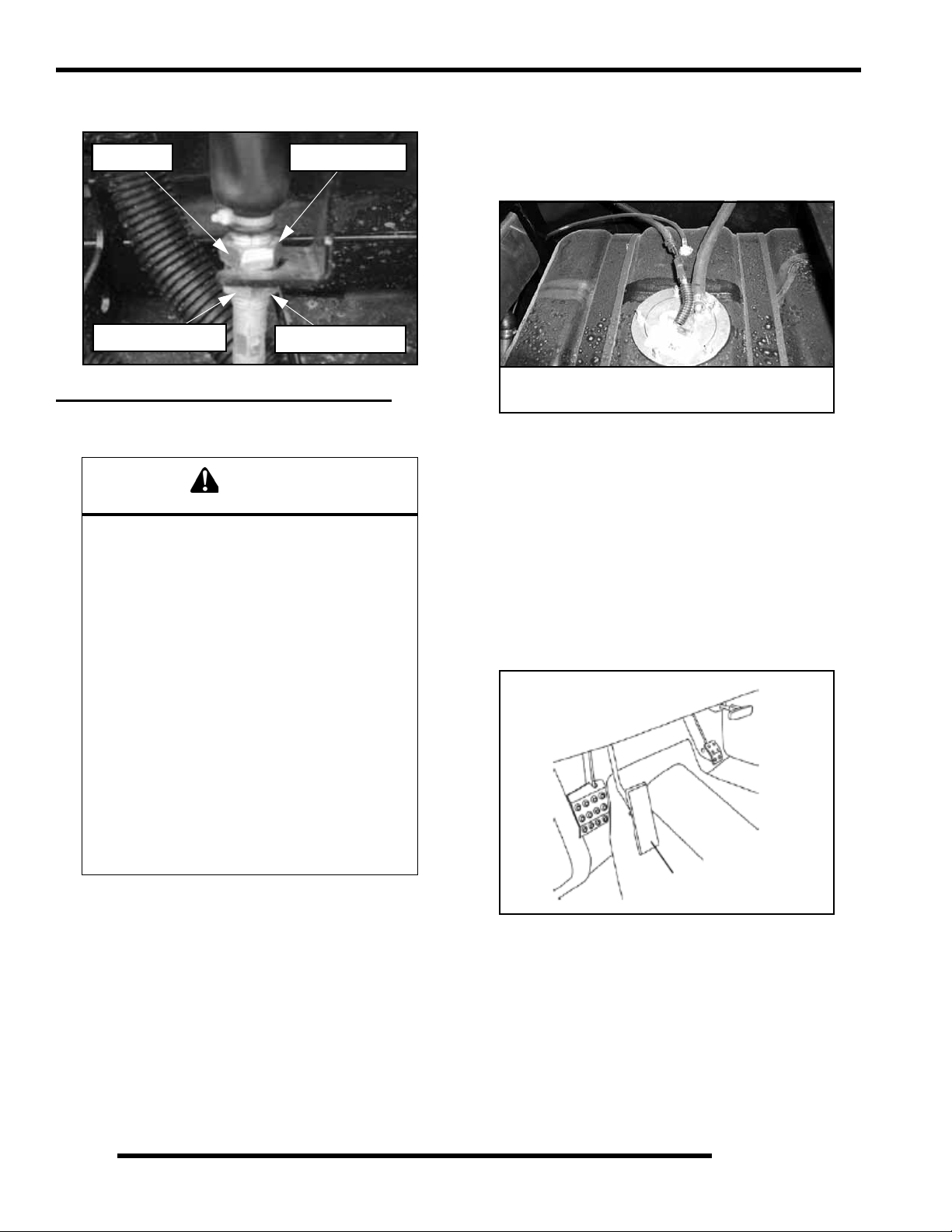
Fuel Filter
The RANGER XP 4x4 and 6x6 EFI engines use a nonserviceable, high-volume, high-pressure, 60-micron internal
fuel pump filter and an internal 10-micron filter located before
the pump regulator. Neither filter is servicable.
Fuel filter in tank is not serviceable
NOTE: For all other information related to the EFI
fuel system refer to Chapter 4.
Vent Lines
1. Check fuel tank and transmission vent lines for signs of
wear, deterioration, damage or leakage. Replace every
two years.
2. Be sure vent lines are routed properly and secured with
cable ties. CAUTION: Make sure lines are not kinked or
pinched
Throttle Pedal Inspection
Throttle Pedal
Fuel Lines
1. Check fuel lines for signs of wear, deterioration, da mage
or leakage. Replace if necessary.
2. Be sure fuel lines are routed properly and secured with
cable ties. CAUTION: Make sure lines are not kinked or
pinched.
3. Replace all fuel lines every two years.
2.14
If the throttle pedal has excessive play due to cable stretch or
cable misadjustment, it will cause a delay in throttle speed.
Also, the throttle may not open fully. If the throttle pedal has no
play , the throttle may be hard to control, and the idle speed may
be erratic.
Check the throttle pedal play periodically in accordance with the
Periodic Maintenance Chart and adjust the play if necessary.
Page 31

GENERAL INFORMATION
Throttle Freeplay Adjustment
Inspection
1. Apply the parking brake.
2. Put the gear shift lever in the N (Neutral) position.
3. Start the engine, and warm it up thoroughly.
4. Measure the distance the throttle pedal moves before the
engine begins to pick up speed. Free play should be 1/16”
- 1/8” (1.5 - 3 mm).
Adjustment
1. Remove the seat.
2. Locate the throttle cable adjuster.
3. Squeeze the end of the rubber boot and slide it far enough
to expose the end of the inline cable adjuster.
Boot
Lock Nut
4. Loosen the adjuster lock nut.
5. Rotate the boot to turn the adjuster until 1/16" to 1/8"
(1.5 - 3 mm) of freeplay is achieved at the throttle pedal.
Adjuster
Air Filter Service
It is recommended that the air filter be replaced annually. When
riding in extremely dusty conditions replacement will be
required more often.
The filter should be inspected periodically before each ride,
using the following procedure.
1. Lift the box to access the filter box cover.
Air Box Location
2. Remove clips (2) from air box cover and remove cover.
Inspect the gasket. It should adhere tightly to the cover and
seal all the way around.
3. Remove air filter assembly. Do not clean the main filter,
the filter should be replaced.
4. Inspect main element and replace if necessary. If the filter
has been soaked with fuel or oil it must be replaced.
Breather Filter
2
NOTE: While adjusting, lightly flip the throttle pedal
up and down.
6. Tighten the lock nut.
7. Squeeze the end of the rubber boot and slide it over the
cable adjuster to its original position.
Cover Seal
Filter
Cover
Installation
1. Reinstall the filter into the air box container. Be sure the
filter fits tightly in the air box.
NOTE: Apply a small amount of general purpose
grease to the sealing edges of the filter before
installing.
2.15
Page 32

GENERAL INFORMATION
2. Check air box. If oil or water deposits are found, drain them
into a suitable container.
NOTE: Service more frequently if vehicle is operated
in wet conditions or at high throttle openings for
extended periods.
3. Install air box cover and secure with clips.
Air Intake Inspection
1. Lift the hood.
2. Inspect the foam inserts in the air baffle boxes. If the foam
inserts are dirty, clean the foam with a high flash point
solvent, followed by hot soapy water.
3. Rinse and dry the foam thoroughly.
4. Inspect the foam for tears or damage. Replace if necessary.
Foam
5. Reinstall the foam inserts into the air baffle boxes.
Air Baffing
Box
Air Box
Engine Intake Duct
PVT Intake Duct
2.16
Page 33
GENERAL INFORMATION
ENGINE
Compression and Leakdown Test
NOTE: This engine does NOT have decompression
components. Compression readings will vary in
proportion to cranking speed during the test.
Average compression (measured) is about 150-200
psi during a compression test.
A smooth idle generally indicates good compression. Low
engine compression is rarely a factor in running condition
problems above idle speed. Abnormally high compression can
be caused by carbon deposits in the combustion chamber or
worn, damaged exhaust cam lobes. Inspect camshaft and
combustion chamber if compression is abnormally high.
A cylinder leakdown test is the best indication of engine
condition. Follow manufacturer's instructions to perform a
cylinder leakage test. (Never use high pressure leakage testers,
as crankshaft seals may dislodge and leak).
Cylinder Compression
Standard: 150-200 PSI
Cylinder Leakdown
Service Limit 15%
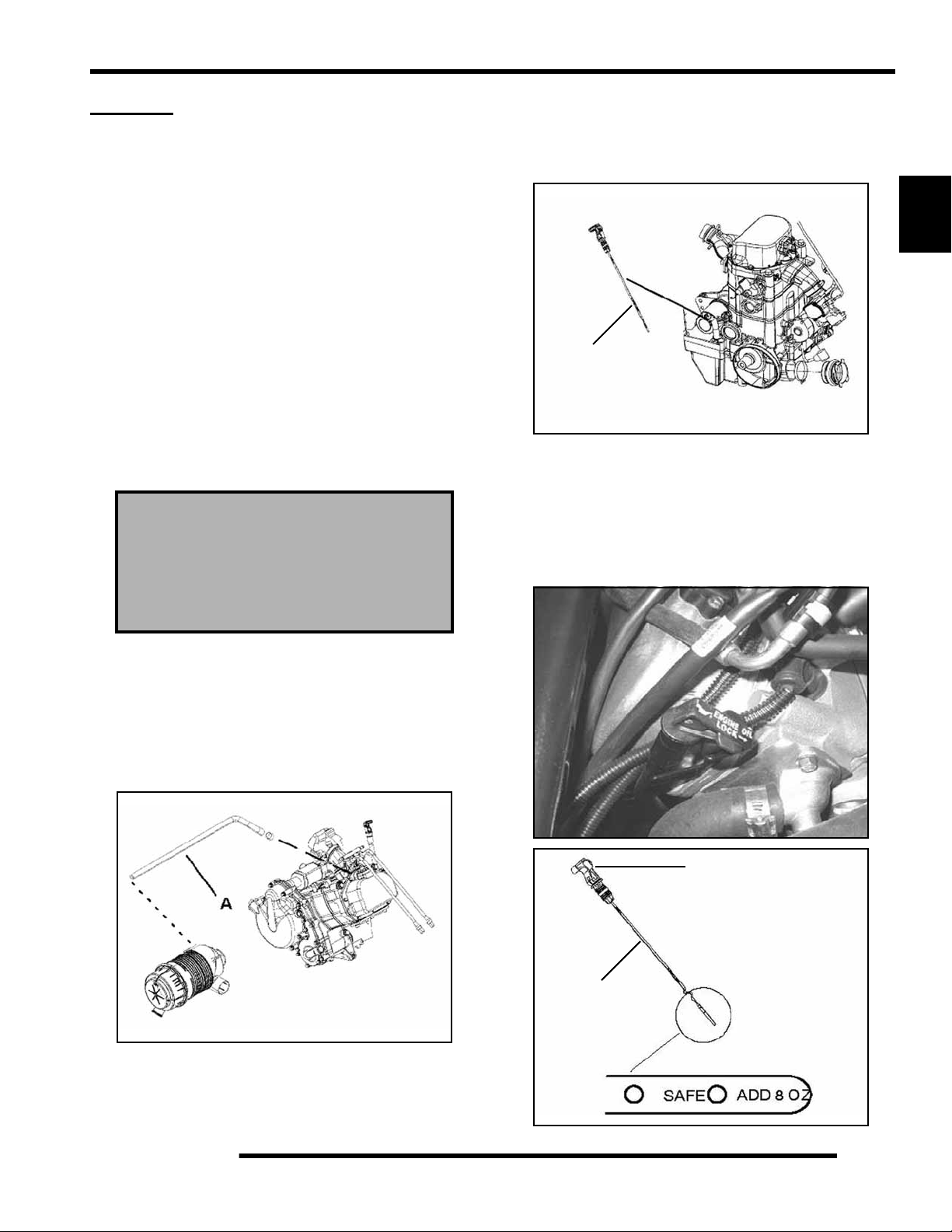
Engine Oil Level
The twin cylinder engine is a wet-sump engine, meaning the oil
is contained in the bottom of the crankcase. To check the oil
level follow the procedure listed below.
2
Dipstick
1. Set machine on a level surface and set the parking brake.
2. Be sure the machine has sat for awhile before removing the
dipstick.
IMPORTANT: Do not run the machine and then check
the dipstick.
3. Stop engine and unlock the lever lock. Remove dipstick
and wipe dry with a clean cloth.
(Inspect for cause if test exceeds 15%)
Breather Hose Inspection
The engine is equipped with a breather hose (A). Inspect the
breather hose for possible kinks or wear. The hose is form fitted for a proper fit. Follow the breather hose from the side of
the airbox to the engine valve cover.
NOTE: Make sure lines are not kinked or pinched.
Lever Lock
Dipstick
2.17
Page 34

GENERAL INFORMATION
4. Reinstall dipstick and push it into place. Do not lock the
dipstick.
NOTE: Make certain the dipstick is inserted all the
way into the filler tube to keep the an gle and dep th of
dipstick consistent. When reinstalling the dipstick,
make certain to seat the lever lock.
5. Remove dipstick and check to see that the oil level is in the
normal range. Add oil as indicated by the level on the
dipstick. Do not overfill. (See NOTE below!)
NOTE: Due to the dipstick entry angle into the
crankcase, the oil level will read higher on the
bottom side of the dipstick. Proper level indication
is determined on the upper surface of the dipstick as
it is being removed, regardless of the level marks
being on top or on bottom. (See the next illustration)
Dipstick
Always read top side of dipstick to
properly check oil level in crankcase
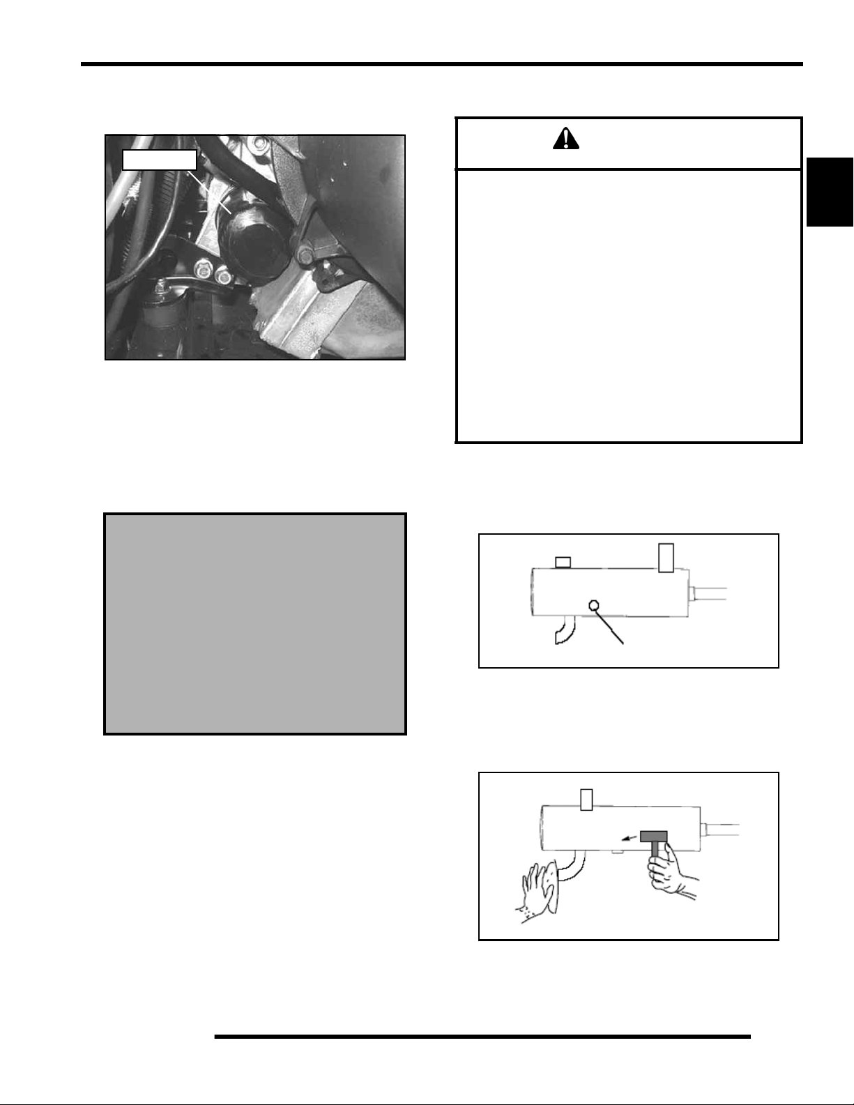
Engine Oil and Filter Change
WARNING
Personal injury can occur when handling used
oil. Hot oil can cause burns or skin damage.
Recommended Engine Oil:
Polaris Premium Synthetic OW-40
(PN 2871281) (Quart)
Ambient Temperature Range
-40° F to 120° F
1. Place vehicle on a level surface.
2. To ease access to the oil filter, try to access the oil filter from
the front engine cover or remove the storage container
located under the driver side seat (refer to Chapter 5 for
front engine cover and storage removal).
3. Run engine two to three minutes until warm. Stop engine.
4. Clean area around drain plug at bottom of oil engine. Drain
plug is accessible through the skid plate.
NOTE: A rising oil level between checks in cool
weather driving can indicate contaminants such as
gas or moisture collecting in the crankcase. If the oil
level is over the full mark, change the oil
immediately.
CAUTION
Oil may be hot. Do not allow hot oil to come into
contact with skin, as serious burns may result.
5. Place a drain pan beneath crankcase and remove drain plug.
Drain Plug
6. Allow oil to drain completely.
7. Replace the sealing washer on drain plug.
NOTE: The sealing surface on the drain plug should
be clean and free of burrs, nicks or scratches.
2.18
8. Reinstall drain plug and torque to 192 ± 24 in. lbs. (21.7 ±
2.7 Nm).
Page 35
GENERAL INFORMATION
9. Place shop towels beneath oil filter. Using Oil Filter
Wrench (PV-43527), turn filter counterclockwise to
remove.
Oil Filter
10. Using a clean dry cloth, clean filter sealing surface on
crankcase.
11. Lubricate O-ring on new filter with a film of fresh engine
oil. Check to make sure the O-ring is in good condition.
12. Install new filter and turn by hand until filter gasket contacts
the sealing surface, then turn an additional 1/2 turn.
13. Remove dipstick and fill sump with 2 quarts (1.9 l) of
Polaris Premium 4 Synthetic Oil (PN2871281)
Crankcase Drain Plug Torque:
192 ± 24 in. lbs. (21.7 ± 2.7 Nm)
Exhaust Pipe
WARNING
Do not perform clean out immediately after the engine
has been run, as the exhaust system becomes very hot.
Serious burns could result from contact with exhaust
components.
To reduce fire hazard, make sure that there are no
combustible materials in the area when purging the
spark arrestor.
Wear eye protection.
Do not stand behind or in front of the vehicle while
purging the carbon from the spark arrestor.
Never run the engine in an enclosed area. Exhaust
contains poisonous carbon monoxide gas.
Do not go under the machine while it is inclined. Set the
hand brake and block the wheels to prevent roll back.
Failure to heed these warnings could result in serious
personal injury or death.
The exhaust pipe must be periodically purged of accumulated
carbon as follows:
1. Remove the clean out plugs located on the bottom of the
muffler as shown below.
2
Oil Filter Torque:
Turn by hand until filter gasket contacts
sealing surface, then turn an
additional 1/2 turn
Oil Filter Wrench:
(PV-43527)
14. Place gear selector in neutral and set parking brake.
15. Start the engine and let it idle for one to two minutes.
Stop the engine and inspect for leaks.
16. Re-check the oil level on the dipstick and add oil as
necessary to bring the level to the upper mark on the
dipstick.
17. Dispose of used oil and oil filter properly.
Clean Out Plug
2. Place the transmission in Park and start the engine. Purge
accumulated carbon from the system by momentarily
revving the engine several times.
3. If some carbon is expelled, cover the exhaust outlet and
lightly tap on the pipe around the clean out plugs with a
rubber mallet while revving the engine several more times.
2.19
Page 36

GENERAL INFORMATION
4. If particles are still suspected to be in the muffler, back the
machine onto an incline so the rear of the machine is one
foot higher than the front. Set the hand brake and block the
wheels. Make sure the machine is in Park and repeat Steps
2 and 3. SEE WARNING
5. If particles are still suspected to be in the muffler, drive the
machine onto the incline so the front of the machine is one
foot higher than the rear. Set the hand brake and block the
wheels. Make sure the machine is in Park and repeat Steps
2 and 3. SEE WARNING
1 ft.
6. Repeat steps 2 through 5 until no more particles are
expelled when the engine is revved.
7. Stop the engine and allow the arrestor to cool.
8. Reinstall the clean out plugs.
The transmission lubricant level should be checked and changed
in accordance with the maintenance schedule.
• Be sure vehicle is level with the parking brake on
before proceeding.
• Check vent hose to be sure it is routed properly and
unobstructed.
To check the level:
1. Remove the fill plug on the backside of the transmission.
Fill Plug
2. The fluid should be at the bottom of the fill plug hole
threads.
Figure 7-26
TRANSMISSION AND GEARCASES
Transmission Lubrication
NOTE: It is very important to follow a regular
transmission fluid check/change schedule. The
service manual of the RANGER recommends the
level be checked every twenty-five (25) hours of
operation, and changed once (1) a year.
TRANSMISSION SPECIFICATIONS
Specified Lubricant:
AGL Synthetic Gearcase Lubricant
(PN 2873602) (32 oz.)
Approximate Capacity at Change:
15.2 oz. (450 ml.)
Drain Plug / Fill Plug Torque:
14 ft. lbs. (19 Nm)
Fill Plug Threads
Proper
Fluid
Level
2.20
Page 37

GENERAL INFORMATION
To change lubricant:
1. Remove skid plate (if necessary).
2. Place a drain pan beneath the transmission oil drain plug
area.
3. Remove the drain plug and wipe the magnetic end clean to
remove accumulated metallic filings.
TRANSMISSION
Drain Plug
14 ft. lbs.
(19 Nm)
4. After the oil has drained completely, install the drain plug.
Torque to 14 ft. lbs. (19 Nm).
5. Add the proper lubricant through the fill plug hole until the
oil level is at the bottom of the fill plug threads (see figure
7-26). Do not overfill.
• The correct front gearcase lubricant to use is Polaris
Premium Demand Hub Fluid.
Front Gearcase Specifications
Specified Lubricant:
Premium Demand Drive Hub Fluid
(PN 2871654)
Capacity: 5.0 oz. (150 ml.)
Fill Plug Torque: 8-30 ft. lbs. (11-41 Nm)
Drain Plug Torque: 10 ft. lbs. (14 Nm)
FRONT GEARCASE
Make sure vent is unobstructed
Fill Plug
8-30 ft. lbs.
(11-41 Nm)
2
6. Torque fill plug to 14 ft. lbs. (19 Nm)
7. Check for leaks.
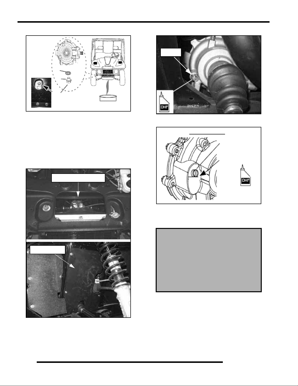
Front Gearcase Lubrication
The gearcase lubricant level should be checked and changed in
accordance with the maintenance schedule.
• Be sure vehicle is level with parki ng brake on before
proceeding.
• Check vent hose to be sure it is routed properly and
unobstructed.
Drain Plug: 10 ft. lbs. (14 Nm)
To check the lubricant level:
The front gearcase lubricant level cannot be checked with a
dipstick. The gearcase must be drained and re-filled with the
proper amount of lubricant or be filled to the bottom of the fill
plug hole threads. Refer to procedures.
2.21
Page 38
GENERAL INFORMATION
To change gearcase lubricant:
A
B
10 ft. lbs (14 Nm)
1. Remove gearcase drain plug (B) (11 mm) located on the
bottom of the gearcase and drain oil. (The drain plug is
accessible through the skid plate.) Catch and discard used
oil properly.
2. Clean and reinstall drain plug (B) using a new sealing
washer (A). Toque to 10 ft. lbs. (14 Nm).
3. The fill plug can be accessed through the top hood area by
removing the storage box or by removing the left side panel
in the left wheel well.
4. Remove fill plug (8 mm hex) and check the O-ring.
Fill Plug
5. Fill with the recommended fluid amount (5 oz.) or to the
bottom of the fill plug hole threads.
Front Gearcase
Plug Threads
Fill with 5 oz.
Top View of Hood Area
LH Side Panel
6. Install fill plug and check for leaks.
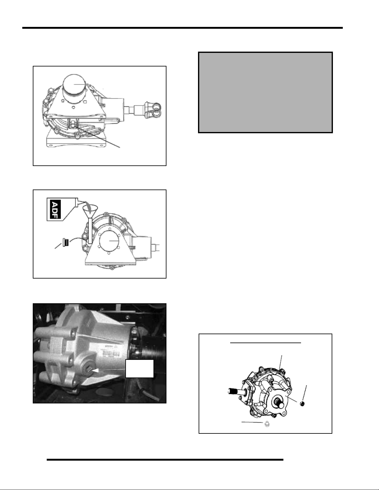
Middle Gearcase Lubrication (6x6)
Middle Gearcase Specifications
Specified Lubricant:
ATV Angle Drive Fluid (PN 2871653)
Capacity: 6.75 oz. (200 ml.)
Drain Plug / Fill Plug Torque:
14 ft. lbs. (19.4 Nm)
The gearcase lubricant level should be checked and changed in
accordance with the maintenance schedule.
• Be sure vehicle is level with parking brak e on befo re
proceeding.
2.22
• Check vent hose to be sure it is routed properly and
unobstructed.
• The correct middle gearcase lubricant to use is ATV
Angle Drive Fluid
Page 39

GENERAL INFORMATION
To check the lubricant level:
The gearcase must be drained and re-filled with the proper
amount of lubricant. Refer to the procedure below.
To change middle gearcase lubricant:
1. With the RANGER on a level surface, remove the fill plug
and check the lubricant level. Lubricant should be kept at
the specified level, according to the proper gearcase
specifications listed.
2. Support the vehicle securely with a jack stand and remove
the front tire on the driver’s side.
3. Remove gearcase drain plug located on the bottom of the
gearcase and drain oil. (The drain plug is accessible through
the skid plate.) Catch and discard used oil properly.
4. Clean and reinstall drain plug using a new sealing washer.
5. Remove fill plug.
6. Fill with the recommended fluid amount or fill to the
bottom of the threads of the fill plug hole.
7. Install fill plug. Check for leaks.
MIDDLE GEARCASE (6X6)
Make sure vent is unobstructed
Rear Gearcase Lubrication (4x4)
REAR GEARCASE SPECIFICATIONS
Specified Lubricant:
ATV Angle Drive Fluid (PN 2871653)
Capacity: 18 oz. (532 ml)
Fill Plug Torque: 40 ft. lbs. (54 Nm)
Drain Plug Torque: 30-45 in. lbs. (3-5 Nm)
To check the level:
1. With machine on level ground and with the parking brake
on, remove fill plug from rear gearcase.
2. The fluid level should be 0.75 in. (1.9 cm) from the bottom
of the fill plug hole threads. Use a light colored and nonabsorbent measuring instrument (white zip tie) to measure
the depth of the fluid in the rear gearcase. If level is low,
add ATV Angle Drive Fluid (PN 2871653).
2
Side View
Fill to bottom of
fill plug hole
threads: 6.75 oz.
Fill Plug
14 ft. lbs. (19 Nm)
Bottom View
0.75 in.
(1.9 cm)
Measuring
Instrument
0.75 in.
(1.9 cm)
Fluid Level
3. Reinstall fill plug. Tighten to 40 ft. lbs. (54 Nm).
4. Check for leaks.
Drain Plug
14 ft. lbs. (19 Nm)
2.23
Page 40
GENERAL INFORMATION
To change the lubricant:
1. Remove gearcase drain plug located on the bottom and
drain the oil. Catch and discard used oil properly.
Under Side View
Drain Plug
30-45 in. lbs.
(3-5 Nm)
2. Clean and reinstall the drain plug with a new sealing washer
and tighten to 30-45 in. lbs. (3-5 Nm).
3. Remove fill plug.
Rear Gearcase Lubrication (6x6)
Rear Gearcase Specifications
Specified Lubricant:
ATV Angle Drive Fluid (PN 2871653)
Capacity: 10 Oz. (300 ml.)
Drain Plug / Fill Plug Torque:
14 ft. lbs. (19.4 Nm)
The gearcase lubricant level should be checked and changed in
accordance with the maintenance schedule.
• Be sure vehicle is level before proceeding with parking
brake on.
• Check vent hose to be sure it is routed properly and
unobstructed.
• The correct rear gearcase lubricant to use is Polaris
ATV Angle Drive Fluid
To check the lubricant level:
Fill Plug
40 ft. lbs.
(54 Nm)
4. Add 18 oz. (532 ml.) of ATV Angle Drive Fluid
(PN 2871653).
5. Reinstall fill plug. Tighten to 40 ft. lbs (54 Nm).
40 ft. lbs
(54 Nm)
6. Check for leaks.
The gearcase must be drained and re-filled with the proper
amount of lubricant. Refer to the procedure below.
To change rear gearcase lubricant:
1. With the vehicle on a level surface, remove the fill plug
and check the lubricant level. Lubricant should be kept at
the specified level, according to the proper gearcase
specifications listed.
2. Support the vehicle securely with a jack stand and remove
the front tire on the driver’s side.
3. Remove gearcase drain plug located on the bottom of the
gearcase and drain oil. (The drain plug is accessible through
the skid plate.) Catch and discard used oil properly.
4. Clean and reinstall drain plug using a new sealing washer.
REAR GEARCASE - 6X6
Make sure vent is unobstructed
Fill Plug
2.24
Drain Plug
Page 41

GENERAL INFORMATION
5. Remove fill plug (A).
A
6. Fill with 10 oz. (300 ml.) or fill to the bottom of the threads
of the fill plug hole.
7. Install fill plug and torque to 14 ft. lbs (19 Nm). Check for
leaks.
COOLING SYSTEM
Liquid Cooling System Overview
The engine coolant level is controlled or maintained by the
recovery system. The recovery system components are the
recovery bottle, radiator filler neck, radiator pressure cap and
connecting hose.
As coolant operating temperature increases, the expanding
(heated) excess coolant is forced out of the radiator past the
pressure cap and into the recovery bottle. As engine coolant
temperature decreases the contracting (cooled) coolant is drawn
back up from the tank past the pressure cap and into the radiator.
Coolant Level Inspection
The recovery bottle, located on the left side of the machine, must
be maintained between the minimum and maximum levels
indicated on the recovery bottle.
Surge Tank Cap
2
With the engine at operating temperature, the coolant level
should be between the upper and lower marks on the coolant
reservoir. If not:
1. Remove reservoir cap. Inner splash cap vent hole must be
clear and open.
2. Fill reservoir to upper mark with Polaris Premium 60/40
Anti Freeze / Coolant or 50/50 or 60/40 mixture of
antifreeze and distilled water as required for freeze
protection in your area.
3. Reinstall cap.
NOTE: Some coolant level drop on new machines is
normal as the system is purging itself of trapped air.
Observe coolant levels often during the break-in
period.
Overheating of engine could occur if air is not fully purged from
system.
Polaris Premium 60/40 is already premixed and ready to use. Do
not dilute with water.
Surge Tank
NOTE: If overheating is evident, allow system to
cool completely and check coolant level in the
radiator and inspect for signs of trapped air in
system.
2.25
Page 42

GENERAL INFORMATION
Radiator Coolant Level Inspection
NOTE: This procedure is only required if the cooling
system has been drained for maintenance and/or
repair. However, if the recovery bottle has run dry,
or if overheating is evident, the level in the radiator
should be inspected and coolant added if necessary.
Radiator Cap
WARNING
• Straight water or antifreeze may cause the system to
freeze, corrode, or overheat.
Polaris 60/40 Anti-Freeze / Coolant
(PN 2871323)
Cooling System Pressure Test
Refer to Chapter 3 for cooling system pressure test procedure.
Cooling System Hoses
1. Inspect all hoses for cracks, deterioration, abrasion or
leaks. Replace if necessary.
Coolant Lines
Never remove the pressure cap when the
engine is warm or hot. Escaping steam can
cause severe burns. The engine must be cool
before removing the pressure cap.
NOTE: Use of a non-standard pressure cap will not
allow the recovery system to function properly.
To access the radiator pressure cap raise the front hood.
The radiator cap is located on the drivers side.
Coolant Strength / Type
T est the strength of the coolan t using an antifreeze hydrometer.
Antifreeze Hydrometer
• A 50/50 or 60/40 mixture of antifreeze and distilled
water will provide the optimum cooling, corrosion
protection, and antifreeze protection.
• Do not use tap water, straight antifreeze, or straight
water in the system. Tap water contains minerals and
impurities which build up in the system.
Radiator
2. Check tightness of all hose clamps.
CAUTION
Do not over-tighten hose clamps at radiator, or
radiator fitting may distort, causing a restriction
to coolant flow. Radiator hose clamp torque is
36 in. lbs. (4 Nm).
2.26
Page 43

GENERAL INFORMATION
Radiator
1. Check radiator (A) air passages for restrictions or damage.
A
2. Carefully straighten any bent radiator fins.
3. Remove any obstructions with compressed air or low
pressure water.
Coolant Drain / Radiator Removal
1. Remove the front bumper. Remove three bolts that secure
the bumper to the bottom of the frame. Remove six screws
(both sides) that secure the wheel well panel to the frame.
Remove two bolts that secure the top bumper to the frame.
Remove the darts that attach the plastic to the bumper.
4. Remove the outlet radiator hose, inlet radiator hose, surge
tank hose, and overflow hose from the radiator.
5. Remove the radiator.
Inlet Radiator Hose
Outlet Radiator Hose
Surge Tank Hose
Plug
FINAL DRIVE / WHEEL AND TIRE
Wheel, Hub, and Spindle Torque Table
Item Nut Type Specification
2
Bolts
Wheel Well
Bolts
2. Remove two mounting screws that secure the top of the
radiator to the frame. Remove the radiator cap. Pull the
radiator out of the frame at an angle.
NOTE: If you have trouble reaching the top radiator
bolts, remove four screws from the top front of the
hood liner. Prop the front of the hood up 1.5 inches
(38.10 mm) to help remove the top bolts that secure
the radiator to the frame.
3. Remove the drain plug and drain the coolant from the
radiator. Drain the coolant into a suitable container and
properly dispose of the coolant.
Aluminum Wheels
(Cast)
Steel Wheels
(Black / Camo)
Front Spindle Nut - 70 Ft. Lbs. (95 Nm)
Rear & Center Hub
Retaining Nut
Aluminum Wheel
(LE Models)
90 ft. lbs. (122 Nm)
Lug Nut (1) 90 ft. lbs. (122 Nm)
Flange Nut (2) 35 ft. lbs. (47 Nm)
- 110 Ft. Lbs. (150 Nm)
#1
Steel Wheel
(Standard Models)
35 ft. lbs. (47 Nm)
#2
2.27
Page 44

GENERAL INFORMATION
CV Shaft Boot Inspection
Inspect the CV shaft boots in the front and rear of the RANGER
for damage, tears, wear, or leaking grease. If the rubber boot
exhibits any of these symptoms, replace the boot. Refer to
Chapter 7 for CV boot replacement, or have you Polaris dealer
replace the boot.
Inspect Boots
Wheel Removal
Front & Rear
Wheel Nuts (4)
4. Securely tighten the wheel nuts to the proper torque li sted
in the torque table at the beginning of this section.
CAUTION
If wheels are improperly installed it could affect
vehicle handling and tire wear. On vehicles with
tapered rear wheel nuts, make sure tapered end
of nut goes into taper on wheel.
Tire Inspection
• Improper tire inflation may affect vehicle
maneuverability.
• When replacing a tire always use original equipment
size and type.
• The use of non-standard size or type tires may affect
vehicle handling.
Tire Tread Depth
Always replace tires when tread depth is worn to 1/8" (3 mm) or
less.
Tread
Depth 1/8" (3 mm)
Front Hub Nut
70 ft. lbs. (95 Nm)
Rear Hub Nut
110 ft. lbs. (150 Nm)
1. Stop the engine, place the transmission in gear and lock the
parking brake.
2. Loosen the wheel nuts slightly.
3. Elevate the side of the vehicle by placing a suitable stand
under the footrest frame.
4. Remove the wheel nuts and washers and remove the wheel.
Wheel Installation
1. With the transmission in gear and the parking brake
locked, place the wheel in the correct position on the wheel
hub. Be sure the valve stem is toward the outside and
rotation arrows on the tire point toward forward rotation.
2. Attach the washers (if applicable) and wheel nuts and finger
tighten them.
3. Lower the vehicle to the ground.
WARNING
Operating a RANGER with worn tires will
increase the possibility of the vehicle skidding
easily with possible loss of control.
Worn tires can cause an accident.
Always replace tires when the tread depth
measures 1/8", (.3 cm) or less.
2.28
Page 45
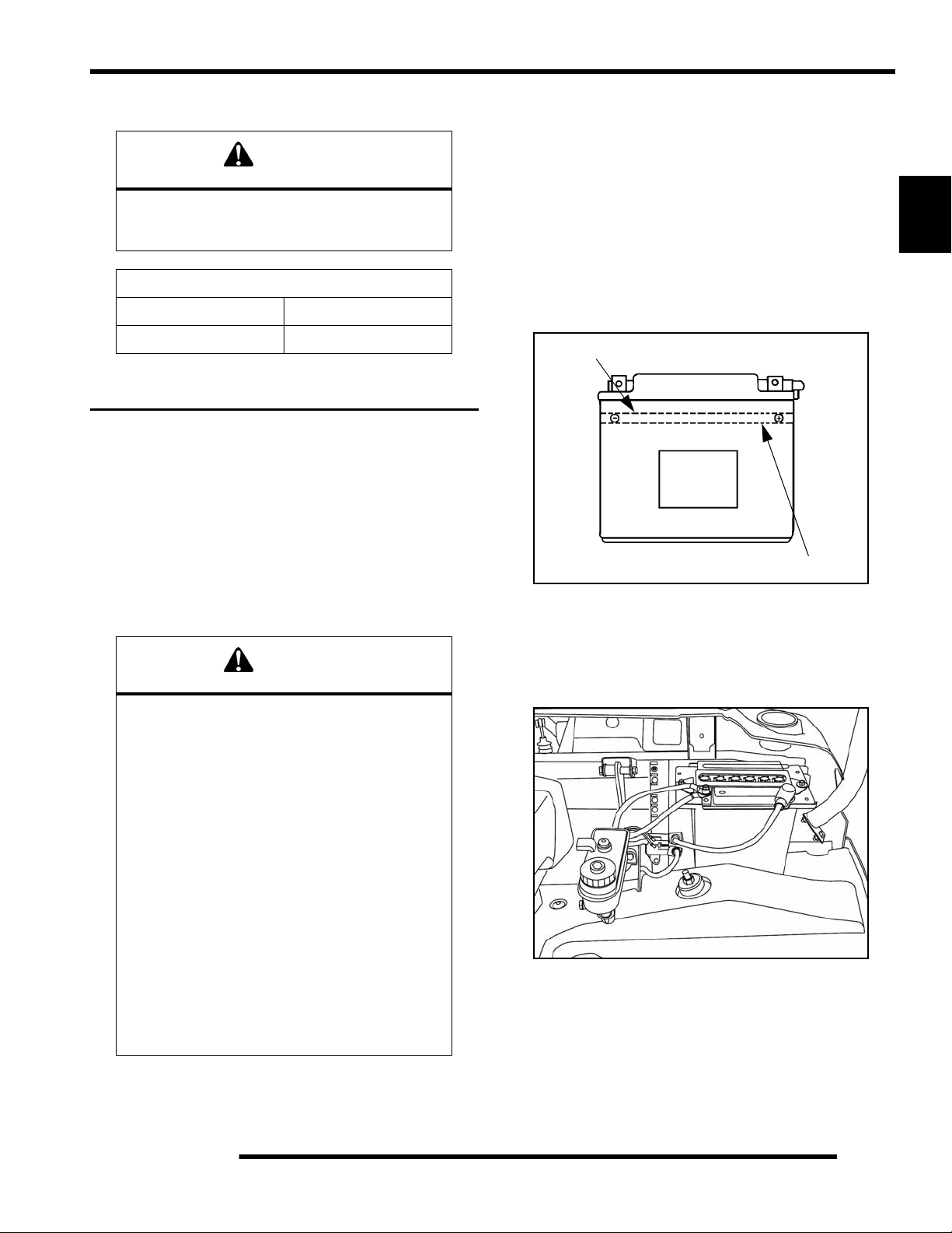
GENERAL INFORMATION
Tire Pressure
CAUTION
Maintain proper tire pressure.
Refer to the warning tire pressure decal
applied to the vehicle.
Tire Pressure Inspection (PSI - Cold)
Front Rear
8-12 8-12
ELECTRICAL AND IGNITION SYSTEM
Battery Maintenance
Keep battery terminals and connections free of corrosion. If
cleaning is necessary, remove th e corrosion with a stiff wire
brush. W ash with a solution of one tablespoon baking soda and
one cup water. Rinse well with tap water and dry off with clean
shop towels. Coat the terminals with dielectric grease or
petroleum jelly.
NOTE: Batteries must be fully charged before use or
battery life will be reduced by 10-30% of full
potential. Charge battery for 3-5 hours at a current
equivalent of 1/10 of the battery’s rated amp/hour
capacity. Do not use the alternator to charge a new
battery. (Refer to Battery Activation and
Maintenance video PN 9917987)
Battery Fluid Level (Conventional Battery)
A poorly maintained battery will deteriorate rapidly. Check the
battery fluid level often. Maintain the fluid level between the
upper and lower level marks.
Upper Level
Lower Level
2
Be careful not to allow cleaning solution or tap water into the
battery
WARNING
Battery electrolyte is poisonous. It contains
sulfuric acid. Serious burns can result from
contact with skin, eyes or clothing. Antidote:
External: Flush with water.
Internal: Drink large quantities of water or milk.
Follow with milk of magnesia, beaten egg, or
vegetable oil. Call physician immediately.
Eyes: Flush with water for 15 minutes and get
prompt medical attention.
Batteries produce explosive gases.
Keep sparks, flame, cigarettes, etc. away.
Ventilate when charging or using in an enclosed
space. Always shield eyes when
working near batteries.
KEEP OUT OF REACH OF CHILDREN.
Add only distilled water. Tap water contains minerals that are
harmful to a battery.
Battery Removal
1. Open the Hood.
2. Remove the battery vent tube from the battery.
3. Disconnect the black (negative) battery cable.
4. Disconnect the red (positive) battery cable.
2.29
Page 46
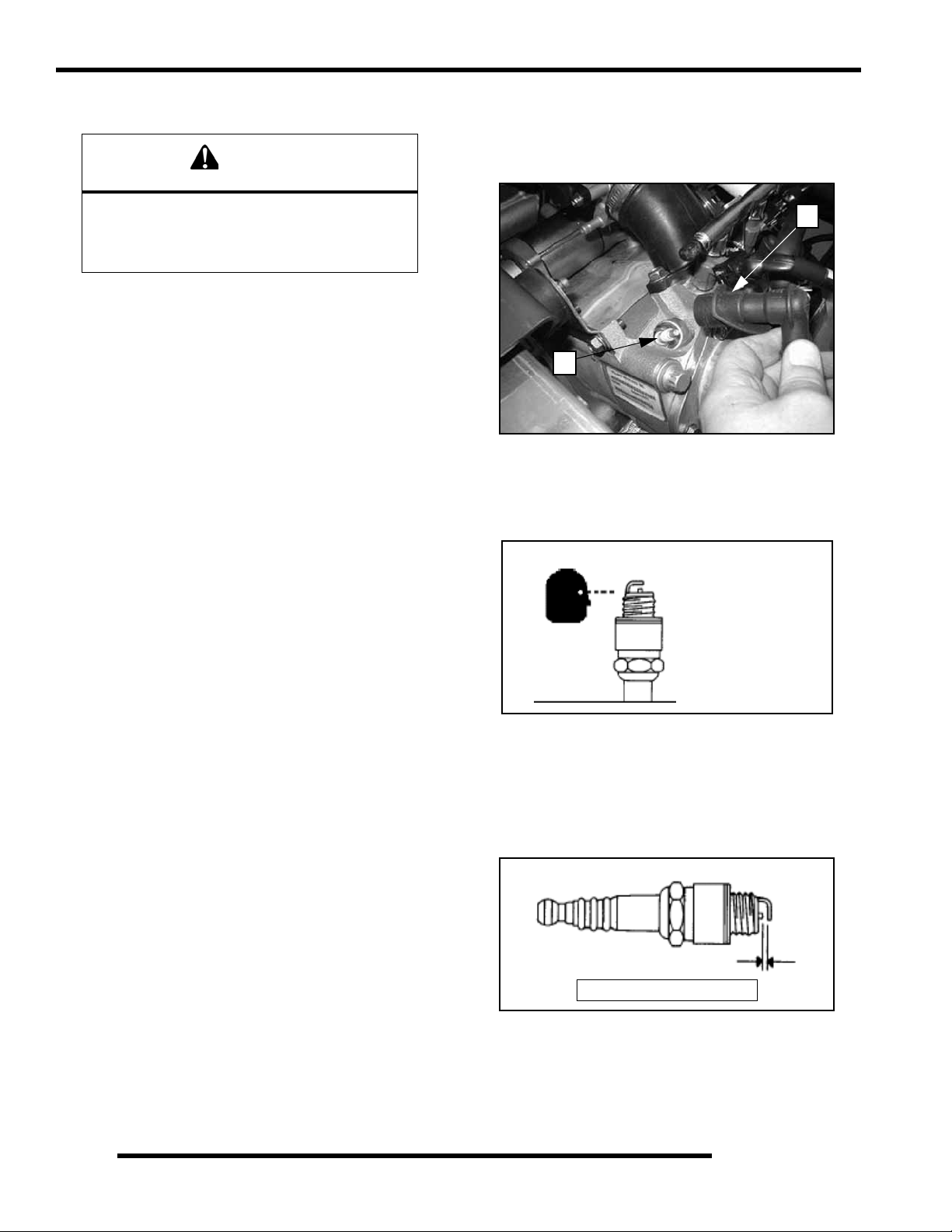
GENERAL INFORMATION
5. Lift the battery out of the vehicle, being careful not to tip
it sideways and spill any electrolyte.
CAUTION
To reduce the chance of sparks: Whenever
removing the battery, disconnect the negative
(black) cable first. When reinstalling the battery,
install the negative cable last.
Battery Installation
Using a new battery that has not been fully charged can damage
the battery and result in a shorter life. It can also hinder vehicle
performance. Follow the battery charging procedure before
installing the battery.
1. Ensure that the battery is fully charged.
2. Place the battery in the battery holder.
3. Install the battery vent tube.
NOTE: The vent tube must be free of obstructions
and securely installed. Rout e t he tu b e aw ay fro m th e
frame and vehicle body to prevent contact with
electrolyte.
4. Coat the terminals with dielectric grease or petroleum jelly.
5. Connect and tighten the red (positive) cable first.
6. Connect and tighten the black (negative) cable last.
7. Verify that cables are properly routed.
Spark Plug Service
1. Remove both spark plug high tension leads (A). Clean
plug area so no dirt and debris can fall into engine when
plug is removed.
A
B
2. Remove spark plugs (B).
3. Inspect electrodes for wear and carbon buildup. Look for
a sharp outer edge with no rounding or erosion of the
electrodes.
Inspect electrode for
wear and buildup
Battery Storage
Whenever the vehicle is not used for a period of three months or
more, remove the battery from the vehicle, ensure that it's fully
charged, and store it out of the sun in a cool, dry place. Check
battery voltage each month during storage and recharge as
needed to maintain a full charge.
NOTE: Battery charge can be maintained by using a
Polaris battery tender charger or by charging about
once a month to make up for normal self-discharge.
Battery tenders can be left connected during the
storage period, and will automatically charge the
battery if the voltage drops below a pre-determined
point.
Battery Charging
1. Remove the battery from the vehicle to prevent damage
from leaking or spilled electrolyte during charging.
2. Charge the battery with a charging output no larger than
1/10 of the battery’s amp/hr rating. Charge as needed to
raise the specific gravity to 1.270 or greater.
3. Reinstall the battery.
4. Clean with electrical contact cleaner or a glass bead spark
plug cleaner only. CAUTION: A wire brush or coated
abrasive should not be used.
5. Measure gap with a wire gauge. Refer to specifications in
picture below for proper spark plug type and gap. Adjust
gap if necessary by bending the side electrode carefully.
Spark Plug Gap
Gap - .035" (0.90 mm)
6. If necessary, replace spark plug with proper type.
CAUTION: Severe engine damage may occur if the
incorrect spark plug is used.
7. Apply a small amount of anti-seize compound to the spark
plug threads.
2.30
Page 47
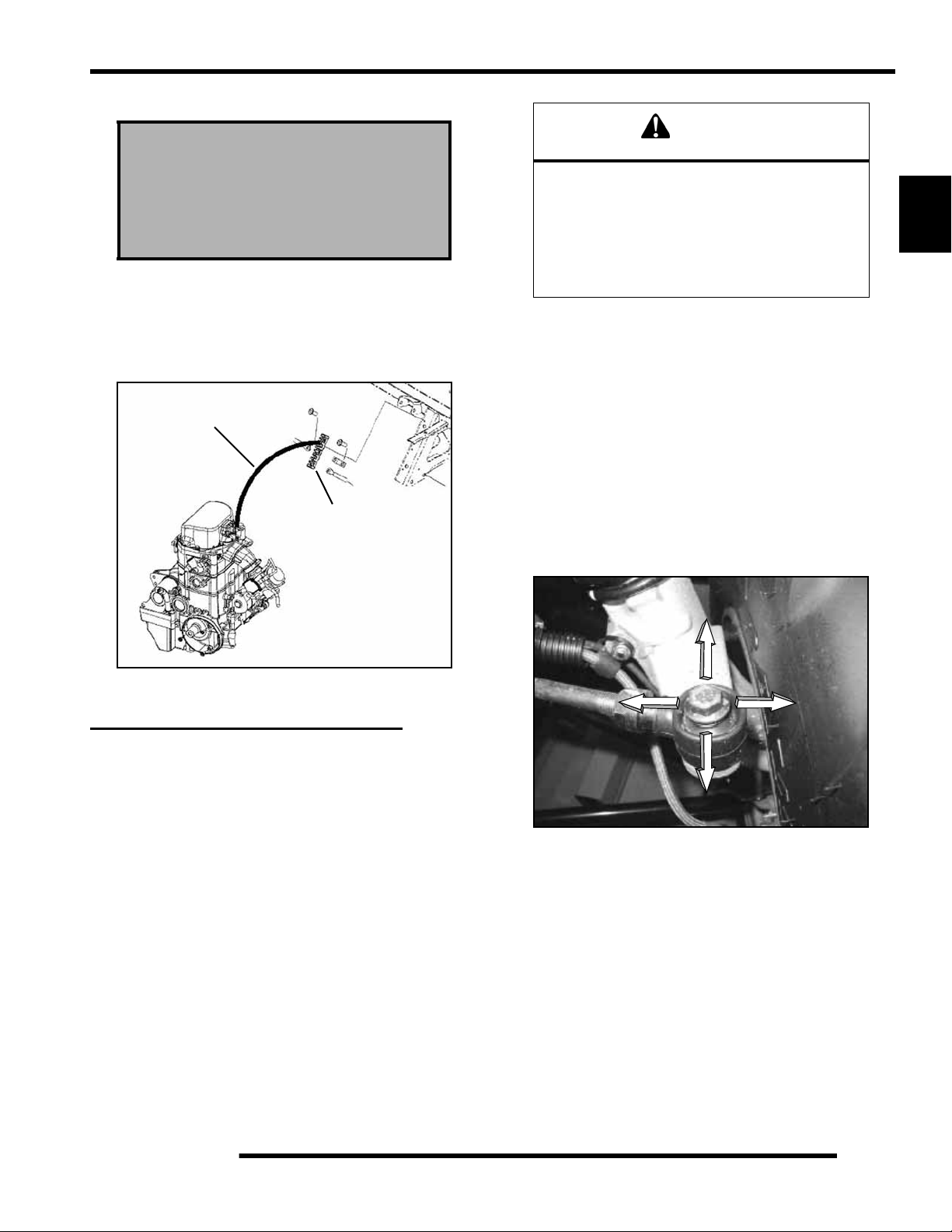
8. Install spark plug and torque to specification
GENERAL INFORMATION
Recommended Spark Plug:
Champion RC7YC3
Spark Plug Torque:
18 Ft. Lbs. (24 Nm)
Engine To Frame Ground
Inspect engine ground cable connection. Be sure it is clean and
tight. The ground cable runs from the engine to the terminal
block located under the front hood next to the battery.
Black Ground
Terminal Block
(under hood)
WARNING
Due to the critical nature of the procedures
outlined in this chapter, Polaris recommends
steering component repair and adjustment be
performed by an authorized Polaris MSD-
certified technician when replacing worn or
damaged steering parts.
Use only genuine Polaris replacement parts.
One of two methods can be used to measure toe alignment. The
string method and the chalk method. If adjustment is required,
refer to following pages for procedure.
Tie Rod End / Steering Inspection
• To check for play in the tie rod end, grasp the steering
tie rod, pull in all directions feeling for movement.
• Repeat inspection for inner tie rod end (on steering
post).
• Replace any worn steering components. Steering
should move freely through entire range of travel
without binding.
2
STEERING AND SUSPENSION
Steering
The steering components should be checked periodically for
loose fasteners, worn tie rod ends, and damage. Also check to
make sure all cotter pins are in place. If cotter pins are removed,
they must not be re-used. Always use new cotter pins.
Replace any worn or damaged steering components. Steering
should move freely through entire range of travel without
binding. Check routing of all cables, hoses, and wiring t o be
sure the steering mechanism is not restricted or limited.
NOTE: Whenever steering components are
replaced, check front end alignment. Use only
genuine Polaris parts.
• Elevate front end of m achin e so front wheels are off the
ground. Check for any looseness in front hub / wheel
assembly by grasping the tire firmly at top and bottom
first, and then at front and rear. Try to move the wheel
and hub by pushing inward and pulling outward.
• If abnorm al movement is detected, inspect the hub and
wheel assembly to determine the cause (loose wheel
nuts or loose front hub nut).
• Refer to the Body/Steering or Final Drive chapter for
more information.
Camber and Caster
The camber and caster are non-adjustable.
2.31
Page 48

GENERAL INFORMATION
Wheel Toe Alignment Inspection
1. Place machine on a smooth level surface.
2. Set steering wheel in a straight ahead position and secure
the steering wheel in this position.
3. Place a chalk mark on the center line of the front tires
approximately 10” (25.4 cm) from the floor or as close to
the hub/axle center line as possible.
Chalk Mark
Measurement “A”
NOTE: It is important that the height of both marks
be equally positioned in order to get an accurate
measurement.
4. Measure the distance between the marks and record the
measurement. Call this measurement “A”.
5. Rotate the tires 180
backward. Position chalk marks facing rearward, even with
the hub/axle centerline.
6. Again measure the distance between the marks and record.
Call this measurement “B”. Subtract measurement “B”
from measurement “A”. The difference between
measurements “A” and “B” is the vehicle toe alignment.
The recommended vehicle toe tolerance is 1/8”, to 1/4”, (.3
to .6 cm) toe out. This means the measurement at the front
of the tire (A) is 1/8”, to 1/4”, (.3 to .6 cm) wider than the
measurement at the rear (B).
by moving vehicle forward or
Measurement “B”
Toe Adjustment
If toe alignment is incorrect, measure the distance between
vehicle center and each wheel. This will tell you which tie rod
needs adjusting.
NOTE: Be sure steering wheel is straight ahead
before determining which tie rod(s) need
adjustment.
CAUTION
During tie rod adjustment, it is very important that
the following precautions be taken when
tightening tie rod end jam nuts.
If the rod end is positioned incorrectly it will not
pivot, and may break.
To adjust toe alignment:
• Hold tie rod end to keep it from rotating.
• Loosen jam nu ts at both end of the ti e rod.
• Shorten or lengthen the tie rod until alignment is as
required to achieve the proper toe setting as specified in
“Wheel Toe Alignment”.
• IMPORTANT: When tightening the tie rod end jam
nuts, the rod ends must be held parallel to prevent rod
end damage and premature wear. Damage may not be
immediately apparent if done incorrectly.
Hold
Rod End
Correctly
Tightened
Jam Nut
Incorrectly
Tightened
Jam Nut
2.32
= In. / mm.
Wheel Toe-Out:
(A) - (B) = 1/8 - 1/4" (.3 to .6 cm)
• After alignmen t is compl ete, torq ue jam nuts to 12-14
ft. lbs. (16-19 Nm).
= T
Tie Rod Jam Nut Torque:
12-14 ft. lbs. (16-19 Nm)
Page 49

GENERAL INFORMATION
Front Suspension
• Compress and release front suspension. Damping
should be smooth throughout the range of travel.
• Check all front suspension components and fasteners
for wear or damage.
• Inspect front strut cartridges for leakage.
Bolt Torque
15 ft. lbs. (20 Nm)
Inspect for leaks
Rear Suspension
2
RANGER 4X4
Independent Rear Suspension
RANGER 6X6
Rear Swingarm Suspension
• Compress and release rear suspension. Damping should
be smooth throughout the range of travel.
• Check all rear suspension components for wear or
damage.
• Inspect shock for leakage.
2.33
Page 50

GENERAL INFORMATION
Rear Suspension Adjustment (4x4)
The rear suspension may be adjusted to provide a stiffer
suspension if necessary.
1. Remove the top shock mounting bolts from the inside
mounting holes.
2. Reposition the shocks to the outside mounting holes.
3. Reinstall the shock mounting bolts. Torque to 30 ft. lbs. (40
Nm).
Outside Mounting Holes
Inside Mounting Holes
BRAKE SYSTEM
Brake System Inspection
The following checks are recommended to keep the brake
system in good operating condition. Service life of brake system
components depends on operating conditions. Inspect brakes in
accordance with the maintenance schedule and before each ride.
• Keep fluid level in the m aster cylinder reservoir to the
indicated level inside reservoir.
• Use Polaris DOT 3 or DOT 4 Brake Fluid.
Rear Spring Adjustment
The rear shock absorber springs are adjusted by rotating the
adjustment cam either clockwise or counterclockwise to
increase or decrease spring tension.
To adjust the suspension, use the adjustment cam located near
the bottom of the rear shock. This will allow you to increase or
decrease the amount of spring preload.
Rear Spring
Adjustment Cam
• Check brake system for fluid leaks.
• Check brake for excessive travel or spongy feel.
• Check friction pads fo r wear, damage or looseness.
• Check surface condition of the disc.
Brake Pad Inspection
Pads should be changed when the friction material is worn to
.180" (4.6 mm). When the pad are new the thickness is .298 ±
.007" (7.56 ± .178 mm).
Brake Pad
Measure
Thickness
Service Limit - .180" (4.6 mm)
2.34
Shock Spanner Wrench
(PN 2870872)
Page 51

Parking Brake Pad Inspection
Measure the thickness of the rear caliper parking brake pads.
Replace assembly as needed. See illustration below for proper
readings.
Inboard Pad Thickness
New .304” (7.72 mm)
Limit: 0.24” (6.1 mm)
GENERAL INFORMATION
2
Inboard
Pad
Outboard
Pad
Outboard Pad Thickness
New 0.360” (9.14 mm)
Limit: 0.31” (7.87 mm)
Installed Disc to Park Brake
0.375” (0.953 cm)
New Rotor Disc Thickness
0.150” - 0.164”
(3.81 - 4.16 mm)
Brake Hose and Fitting Inspection
Check brake system hoses and fittings for cracks, deterioration,
abrasion, and leaks. Tighten any loose fittings and replace any
worn or damaged parts.
2.35
Page 52

ENGINE
CHAPTER 3
ENGINE
ENGINE SPECIFICATIONS . . . . . . . . . . . . . . . . . . . . . . . . . . . . . . . . . . . . . . . . . . . . . . . 3.2
CRANKCASE EXPLODED VIEWS . . . . . . . . . . . . . . . . . . . . . . . . . . . . . . . . . . . . . . . . . 3.2
ENGINE FASTENER TORQUE PATTERNS . . . . . . . . . . . . . . . . . . . . . . . . . . . . . . . . . . 3.9
TORQUE SPECIFICATIONS . . . . . . . . . . . . . . . . . . . . . . . . . . . . . . . . . . . . . . . . . . . . . 3.10
700 EFI ENGINE SERVICE SPECIFICATIONS. . . . . . . . . . . . . . . . . . . . . . . . . . . . . . . 3.11
SPECIAL TOOLS . . . . . . . . . . . . . . . . . . . . . . . . . . . . . . . . . . . . . . . . . . . . . . . . . . . . . . 3.13
GENERAL ENGINE SERVICE . . . . . . . . . . . . . . . . . . . . . . . . . . . . . . . . . . . . . . . . . . . . 3.13
ACCESSIBLE COMPONENTS. . . . . . . . . . . . . . . . . . . . . . . . . . . . . . . . . . . . . . . . . . . . 3.13
PISTON IDENTIFICATION. . . . . . . . . . . . . . . . . . . . . . . . . . . . . . . . . . . . . . . . . . . . . . . 3.13
COOLING SYSTEM SPECIFICATIONS. . . . . . . . . . . . . . . . . . . . . . . . . . . . . . . . . . . . . 3.13
COOLING SYSTEM PRESSURE TEST. . . . . . . . . . . . . . . . . . . . . . . . . . . . . . . . . . . . . 3.14
COOLING SYSTEM EXPLODED VIEW. . . . . . . . . . . . . . . . . . . . . . . . . . . . . . . . . . . . . 3.15
COOLING SYSTEM BLEEDING PROCEDURE . . . . . . . . . . . . . . . . . . . . . . . . . . . . . . 3.15
VALVE COVER REMOVAL - 6X6 MODELS (ENGINE INSTALLED) . . . . . . . . . . . . . . 3.17
ENGINE REMOVAL . . . . . . . . . . . . . . . . . . . . . . . . . . . . . . . . . . . . . . . . . . . . . . . . . . . . 3.18
ENGINE INSTALLATION NOTES . . . . . . . . . . . . . . . . . . . . . . . . . . . . . . . . . . . . . . . . . 3.19
CYLINDER HONE SELECTION AND HONING PROCEDURE. . . . . . . . . . . . . . . . . . . 3.20
HONING TO DEGLAZE . . . . . . . . . . . . . . . . . . . . . . . . . . . . . . . . . . . . . . . . . . . . . . . . . 3.20
CLEANING THE CYLINDER AFTER HONING . . . . . . . . . . . . . . . . . . . . . . . . . . . . . . . 3.21
ENGINE LUBRICATION SPECIFICATIONS . . . . . . . . . . . . . . . . . . . . . . . . . . . . . . . . . 3.21
OIL PRESSURE TEST . . . . . . . . . . . . . . . . . . . . . . . . . . . . . . . . . . . . . . . . . . . . . . . . . . 3.21
OIL FLOW CHART . . . . . . . . . . . . . . . . . . . . . . . . . . . . . . . . . . . . . . . . . . . . . . . . . . . . . 3.22
ENGINE DISASSEMBLY AND INSPECTION . . . . . . . . . . . . . . . . . . . . . . . . . . . . . . . . . 3.23
CYLINDER HEAD ASSEMBLY EXPLODED VIEW . . . . . . . . . . . . . . . . . . . . . . . . . . . . 3.23
ROCKER ARMS / PUSH RODS. . . . . . . . . . . . . . . . . . . . . . . . . . . . . . . . . . . . . . . . . . . 3.24
CYLINDER HEAD REMOVAL . . . . . . . . . . . . . . . . . . . . . . . . . . . . . . . . . . . . . . . . . . . . 3.24
CYLINDER HEAD INSPECTION . . . . . . . . . . . . . . . . . . . . . . . . . . . . . . . . . . . . . . . . . . 3.25
CYLINDER HEAD WARP. . . . . . . . . . . . . . . . . . . . . . . . . . . . . . . . . . . . . . . . . . . . . . . . 3.25
VALVE SEAL / SPRING SERVICE (ON ENGINE). . . . . . . . . . . . . . . . . . . . . . . . . . . . . 3.25
CYLINDER HEAD DISASSEMBLY . . . . . . . . . . . . . . . . . . . . . . . . . . . . . . . . . . . . . . . . 3.26
VALVE INSPECTION . . . . . . . . . . . . . . . . . . . . . . . . . . . . . . . . . . . . . . . . . . . . . . . . . . . 3.27
COMBUSTION CHAMBER. . . . . . . . . . . . . . . . . . . . . . . . . . . . . . . . . . . . . . . . . . . . . . . 3.28
VALVE SEAT RECONDITIONING . . . . . . . . . . . . . . . . . . . . . . . . . . . . . . . . . . . . . . . . . 3.28
CYLINDER HEAD REASSEMBLY . . . . . . . . . . . . . . . . . . . . . . . . . . . . . . . . . . . . . . . . . 3.30
VALVE SEALING TEST . . . . . . . . . . . . . . . . . . . . . . . . . . . . . . . . . . . . . . . . . . . . . . . . . 3.31
CYLINDER REMOVAL . . . . . . . . . . . . . . . . . . . . . . . . . . . . . . . . . . . . . . . . . . . . . . . . . . 3.31
VALVE LIFTER REMOVAL / INSPECTION . . . . . . . . . . . . . . . . . . . . . . . . . . . . . . . . . . 3.31
PISTON REMOVAL . . . . . . . . . . . . . . . . . . . . . . . . . . . . . . . . . . . . . . . . . . . . . . . . . . . . 3.32
CYLINDER INSPECTION. . . . . . . . . . . . . . . . . . . . . . . . . . . . . . . . . . . . . . . . . . . . . . . . 3.33
PISTON-TO-CYLINDER CLEARANCE . . . . . . . . . . . . . . . . . . . . . . . . . . . . . . . . . . . . . 3.34
PISTON / ROD INSPECTION. . . . . . . . . . . . . . . . . . . . . . . . . . . . . . . . . . . . . . . . . . . . . 3.34
PISTON RING INSTALLED GAP . . . . . . . . . . . . . . . . . . . . . . . . . . . . . . . . . . . . . . . . . . 3.35
STARTER DRIVE BENDIX REMOVAL / INSPECTION . . . . . . . . . . . . . . . . . . . . . . . . . 3.35
FLYWHEEL / STATOR REMOVAL / INSPECTION . . . . . . . . . . . . . . . . . . . . . . . . . . . . 3.36
ENGINE CRANKCASE DISASSEMBLY / INSPECTION . . . . . . . . . . . . . . . . . . . . . . . . 3.36
CAMSHAFT INSPECTION . . . . . . . . . . . . . . . . . . . . . . . . . . . . . . . . . . . . . . . . . . . . . . . 3.44
ENGINE REASSEMBLY . . . . . . . . . . . . . . . . . . . . . . . . . . . . . . . . . . . . . . . . . . . . . . . . . 3.45
CRANKCASE REASSEMBLY . . . . . . . . . . . . . . . . . . . . . . . . . . . . . . . . . . . . . . . . . . . . 3.45
FLYWHEEL / STATOR INSTALLATION . . . . . . . . . . . . . . . . . . . . . . . . . . . . . . . . . . . . 3.54
CYLINDER HEAD REASSEMBLY . . . . . . . . . . . . . . . . . . . . . . . . . . . . . . . . . . . . . . . . . 3.54
OIL PUMP PRIMING . . . . . . . . . . . . . . . . . . . . . . . . . . . . . . . . . . . . . . . . . . . . . . . . . . . 3.57
TROUBLESHOOTING. . . . . . . . . . . . . . . . . . . . . . . . . . . . . . . . . . . . . . . . . . . . . . . . . . . 3.58
ENGINE . . . . . . . . . . . . . . . . . . . . . . . . . . . . . . . . . . . . . . . . . . . . . . . . . . . . . . . . . . . . .3.58
COOLING SYSTEM . . . . . . . . . . . . . . . . . . . . . . . . . . . . . . . . . . . . . . . . . . . . . . . . . . . . 3.59
3
3.1
Page 53

ENGINE
ENGINE SPECIFICATIONS
Crankcase Exploded Views
A. Jo ur n a l B ea rin gs
B. Camshaft
C. Thrust Plate
D. Balance Shaft
E. Woodruff Key
F. Flange Seal
G. Crankshaft
H. Oil Pickup
I. Journal Bearings
J. Baffle
K. Oil Plug
L. Washer
M. O-ring
N. Crankcase
O. Crankcase Bolts
A
D
B
C
115 12 in. lbs.
(13 1.35 Nm)
F
60 6 in. lbs.
(6.8 .68 Nm)
N
G
M
H
E
60 6 in. lbs.
(6.8 .68 Nm)
I
I
NOTE: If needed, heat
the oil baffle bolts with a
heat gun to remove.
192 24 in. lbs
K
(21.7 2.7 Nm
L
J
3.2
O
22 2 ft. lbs. (30 3 Nm)
Apply Loctite 242 to
bolt threads.
Apply White Lithium
Grease
Apply Moly
Lube Grease.
Page 54

Oil Pump / Water Pump / Engine Cover Exploded View
A
B
C
D
E
J
K
L
22 2 ft. lbs. (30 3 Nm)
M
84 8 in. lbs. (9.5 .90 Nm)
A. Split Gear
B. Washer
C. Bolt
D. Oil Rotor
E. Oil Pump
F . Mag Gasket Cover
G. Impeller
H. Washer
I. Nut
J. Counterbalance Gear
K. Washer
L. Bolt
M. Oil Pump Bolts
N. Engine Cover
F
O. Wire Hold down
P . Stator Housing Bolts
ENGINE
3
G
H
I
Oil Pump Bolt Tighten Sequence
No Grease on this
Portion of the Gasket!
Apply corrosion resistant
grease to stator grommet area.
N
O
P
96 3 in.lbs.
(10.85 0.35 Nm)
Mag Cover Bolt Tighten Sequence
Apply Polaris OW-40
oil to component
108 12 in.lbs.
(6.8 .68 Nm)
Apply White Lithium
Grease
3.3
Page 55

ENGINE
Stator Cover / Starter / Water Pump Exploded View
Apply Polaris
Starter Grease
Apply Polaris 0W-40
oil to seal
Loctite Pipe Sealant
(PN 2871956)
A
84 8 ft.lbs. (9.5 0.9 Nm)
Tighten Top Bolt First
1st
2nd
E
108 12 ft.lbs.
(12 1.35 Nm)
F
D
B
C
Water Pump Cover
Bolt Tighten Sequence
J
No Grease or Oil
O
N
3
7
1
K
M
65 7 ft. lbs.
(88 9.5 Nm)
5
2
4
6
L
96 12 in. lbs.
(10.85 1.35 Nm)
A. Bolts
B. Starter
C. Washer
D. Nut
E. Positive Cable
F. Negative Cable
G. Gasket
H. Clamp
I. Bolts
J. Gasket
K. Wa te r Pu m p C o ve r
L. Bolts
M. C ra nk N ut / Was h er
N. Flywheel
G
H
96 12 in. lbs. (10.85 1.35 Nm)
I
Stator Cover Bolt
Tighten Sequence
3.4
Page 56
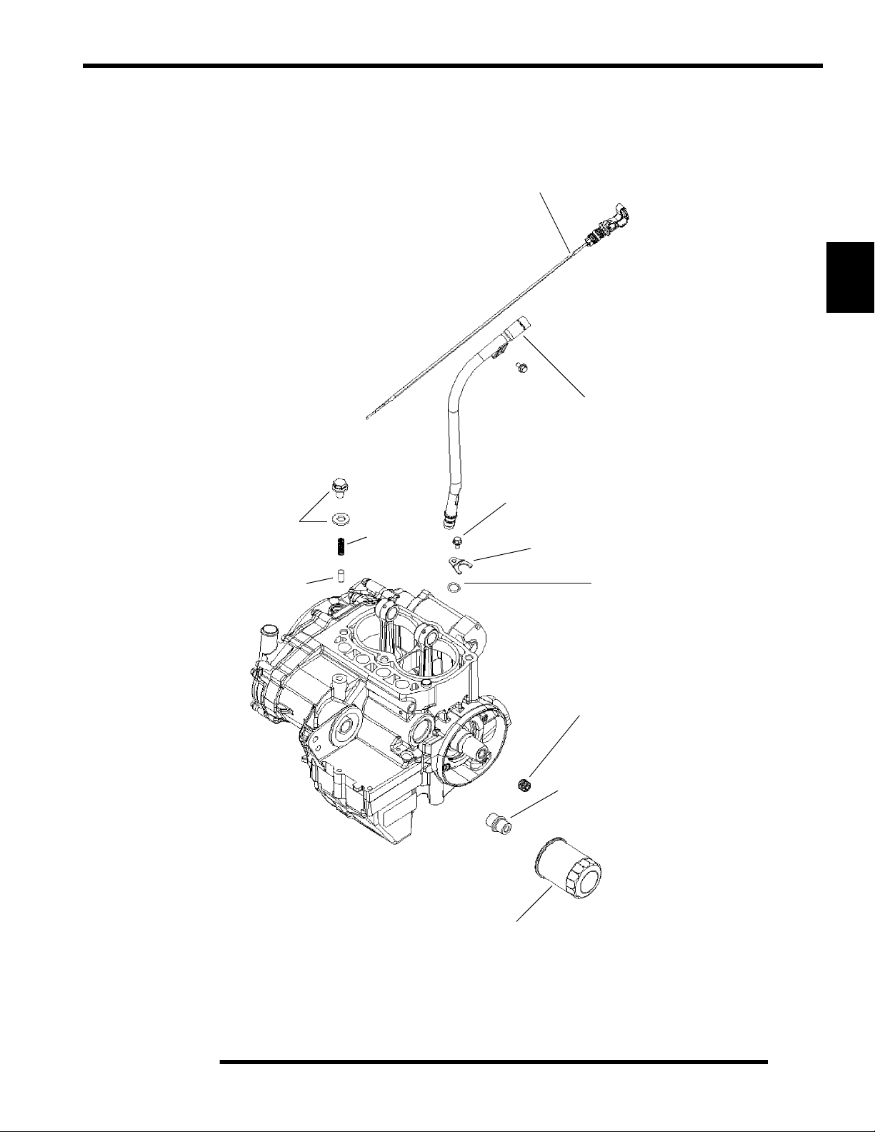
Oil Filter / Pressure Relief / Dipstick Assembly Exploded View
A. Clamp
B. Oil Fill Tube
C. Dipstick
D. O-ring
E. Hex Plug
F. Oil Filter Nipple
G. Oil Filter
H. Dowel
I. Ga l l ey P l u g As m .
J. Screw
K. Relief Spring
C
B
ENGINE
3
22 2 ft. lbs.
(30 3 Nm)
H
50 5 in. lbs.
J
(5.65 0.56 Nm)
I
K
A
D
18 2 ft. lbs.
E
(24.4 2.71 Nm)
35 4 ft. lbs.
F
(47.5 5.4 Nm)
50 5 in. lbs.
(5.65 0.56 Nm)
G
3.5
Page 57
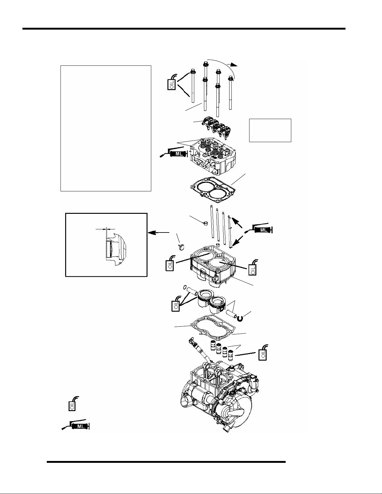
ENGINE
Cylinder / Cylinder Head / Piston Exploded View
Lubricate threads & between
washers and underside of bolt heads
with engine oil.
Torque in sequence pro vided .
Apply Moly Lube grease to
valve tips.
Gasket free of oil. V erify tabs are
visible.
Apply thin film of 0W- 40 to
25-55 mm of cylinder bore.
Apply 0W-40 to piston pin or pin
bore.
Apply 0W- 40 to lifters.
Do Not install expansion plug
more than 1.5 mm inward.
1.5 mm
1
(Apply each
Bolt Threads)
A
22 ± 2 ft. lbs.
(30 ± 3 Nm)
2
C
G
Initial:
4 ft. lbs (47.5 5.5 Nm)
35
in sequence. Finalize sequence
by tightening an additional 90
(1/4 turn)
B
Head Bolt Tighten
Sequence
3
D
F
E
Side View
A. Head Bolts
B. Rocker Arms
C. He ad A ss em bl y
D. Gasket
E. Pushrods
F . Bushing
G. Expansion Plug
H. Cylinder
I. Piston Assembly
J. Circlip
K. Gasket
L. Hydraulic Lifter
Apply Polaris 0W-40 Oil
Apply Moly Lube Grease
4
5
3
4
H
I
Circlip UP
J
for Install
K
L
6
3.6
Page 58

Engine Sensors / Valve Cover / General Component Exploded View
ENGINE
A. Screws
B. Rocker Cover
C. Breather
D. O-ring Seal
E. Breather Bolts
F. Spark Plugs
G. Intake Boot
H. Bolts
I. Boot Clamp
J. Throttle Body
K. Crank Position Sensor
L. Thermistor
M. O-ring
N. Thermostat
O. Bolts
P. Gasket
Q. Exhaust Manifold
R. Bolts
S. Thermostat Housing
20 5 in. lbs.
(2.5 0.55 Nm)
18 2 ft. lbs.
(24.5 2.7 Nm)
20 5 in. lbs.
(2.5 0.55 Nm)
Apply Corrosion
Resistant Grease
84 8 in. lbs.
(9.5 0.9 Nm)
E
18 2 ft. lbs.
(24.5 2.7 Nm)
(Apply Dielectric Grease
to threads of Spark Plug)
G
H
I
A
B
C
3
D
F
J
K
84 4 in. lbs.
(9.5 0.9 Nm)
R
Q
P
18 2 ft. lbs.
(24.5 2.7 Nm)
17 2 ft. lbs.
L
(23 3 Nm)
M
N
S
O
84 8 in. lbs.
(9.5 0.9 Nm)
3.7
Page 59

ENGINE
EFI Harness / Fuel Injection Exploded View
A. Fuel Injector
B. Fuel Rail
C. EFI Harness
18 2 ft. lbs.
(24.5 2.7 Nm)
C
B
A
3.8
NOTE: See Chapter 4 for more information on the EFI system.
Page 60
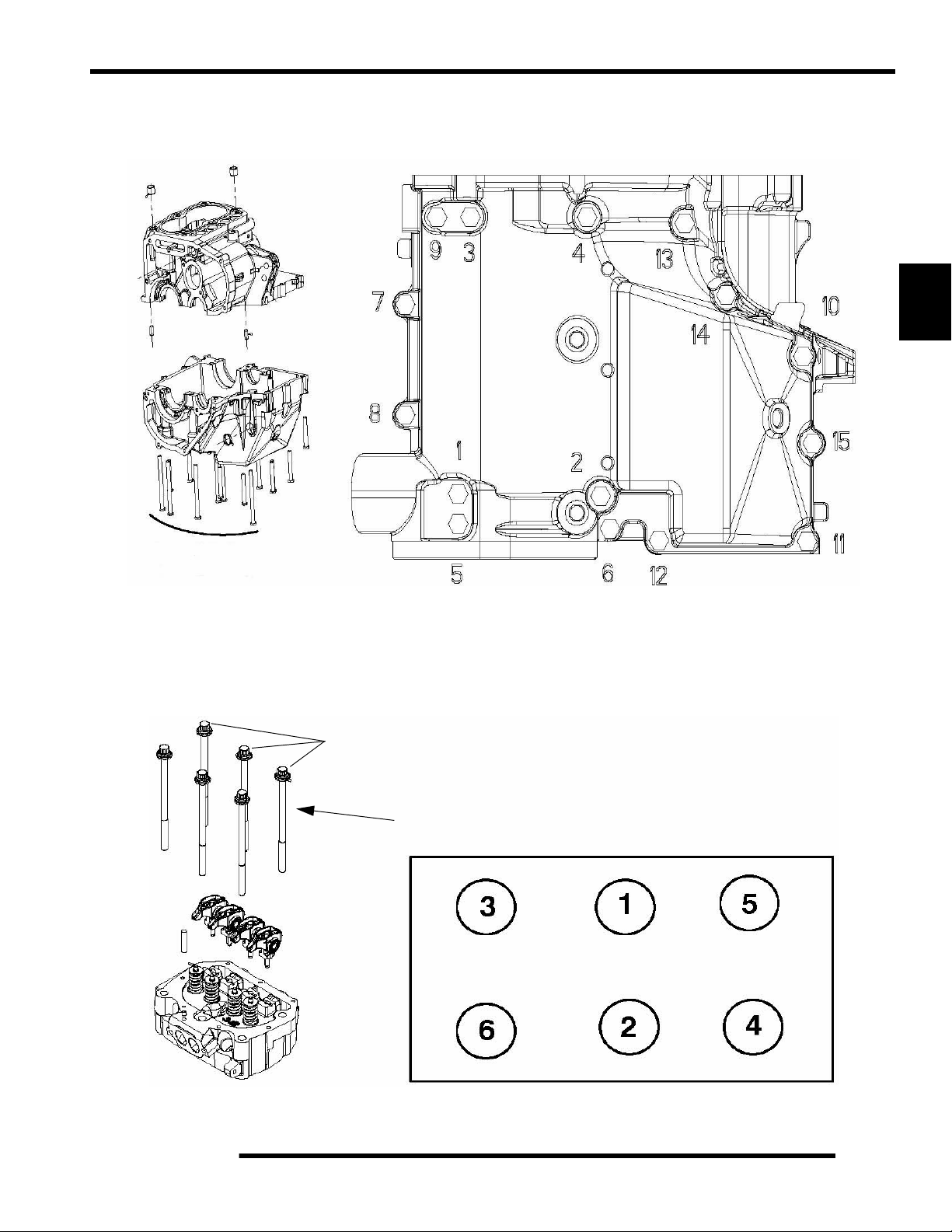
Engine Fastener Torque Patterns
Crankcase Bolt Tighten Sequence
ENGINE
3
22 2 ft. lbs. (30 3 Nm)
Cylinder Head Bolt Tighten Sequence
Lubricate threads and between washer and underside of bolt with engine oil.
Torque in sequence to spec provided, allow the gasket to set for 1 minute, th en
tighten in sequence 90
35 4 ft. lbs.
(47.5 5.5 Nm)
(1/4 turn).
+ 90
(1/4 turn)
3.9
Page 61

ENGINE
Torque Specifications
Engine Torque Specifications
Fastener Size in. lbs. (Nm) ft. lbs. (Nm)
Camshaft Gear 8 mm 22 ± 2 (30 ± 3)
Camshaft Thrust Plate 6 mm 115 ± 12 (13 ± 1.35) 9.5 ± 1 (13 ± 1.35)
Throttle Body Adaptor Bolts 8 mm 216 ± 24 (24.5-± 2.7) 18 ± 2 (24.5 ± 2.7)
Counterbalance Gear 8 mm 22 ± 2 (30 ± 3)
Crankcase Bolts 8 mm * 22 ± 2 (30 ± 3)
Crankcase Breather 5 mm 20 ± 5 (2.5 ± 0.55) Cylinder Head Bolts 11 mm * 35 ± 4 (47.5 ± 5.5)
Exhaust Manifold 8 mm 216 ± 24 (24.5 ± 2.70) 18 ± 2 (24.5 ± 2.7)
Flywheel 14 mm 65 ± 7 (88 ± 9.50)
Injector Rail 8 mm 216 ± 24 (24.5 ± 2.70) 18 ± 2 (24.5 ± 2.7)
Magneto Cover 6 mm * 96 ± 3 (10.8 5 ± 0.35) Oil Baffle Weldment 5 mm 60 ± 6 (6.8 ± 0.68) Oil Drain Bolt (Crankcase) 12 mm 192 ± 24 (21.7 ± 2.7) 16 ± (21.7)
Oil Fill Tube Bolt 5 mm 50 ± 5 (5.64 ± 0.56) Oil Filter Pipe Fitting 20 mm 35 ± 4 (47.5 ± 5.4)
Oil Pick Up 5 mm 60 ± 6 (6.8 ± 0.68) Oil Pressure Relief Plug 10 mm 22 ± 2 (30 ± 3) Oil Pump Housing Screw 6 mm * 84 ± 8 (9.50 ± 0.90) Rocker Arm 8 mm * 22 ± 2 (30 ± 3)
Rocker Cover 6 mm * 84 ± 8 (9.5 ± 0.9) Spark Plug 14 mm 216 ± 24 (24.5 ± 2.7) 18 ± 2 (24.5 ± 2.7)
Starter Motor 6 mm * 84 ± 8 (9.5 ± 0.9) Stator Assembly 6 mm 96 ± 3 (10.85 ± 0.35) Stator Housing 6 mm * 96 ± 3 (10.8 5 ± 0.35) Temperature Switch 3/8 NPT 17 ± 2 (23 ± 3)
Thermostat Housing 6 mm 84 ± 8 (9.5 ± 0.9) Timing Plug 3/4-16 7 - 9 (10 - 12)
Trigger Coil/Stator Wire Holddown 5 mm * 96 ± 3 (10.85 ± 0.35) Water Pump Housing Cover 6 mm * 96 ± 3 (10.85 ± 0.35) Water Pu mp Impeller Nut 8 mm 108 ± 3 (12 ± 0.35) -
NOTE: * See exploded views for notes or torque sequences.
3.10
Page 62

700 EFI Engine Service Specifications
Cylinder Head - Engine Specifications
Main Component: Cylinder Head EH068OLE
Cam Lobe Height - Intake / Exhaust 1.3334" (33.8674 mm)
Camshaft Journal Outer Diameter - Mag 1.654" 0.00039" (42 0.010 mm)
Camshaft Journal Outer Diameter - Center 1.634" 0.00039" (41.50 0.010 mm)
ENGINE
Camshaft Journal Outer Diameter - PTO 1.614" 0.00039" (41 0.010 mm)
Camshaft
Counter Balance Counter Balance End Play 0.0 05" (0.127 mm)
Cylinder Head
Valve Seat
Valve Guide
Camshaft Journal Bore Inner Diameter - Mag 1.656" 0.00039" (42.07 0.010 mm)
Camshaft Journal Bore Inner Diameter - Center 1.637" 0.00039" (41.58 0.010 mm)
Camshaft Journal Bore Inner Diameter - PTO 1.617" 0.0003 9" (41 .0 7 0.010 mm)
Camshaft Oil Clearance 0.00276" 0.00079" (0.07 0.02 mm)
Camshaft End Play 0.0167" 0.0098" (0.425 0.25 mm)
Cylinder Head - Surface warp limit 0.00394" (0.1 mm)
Cylinder Head - Standard height 3.478" (88.3 5 mm )
Valve Seat - Contacting Width - Intake
Valve Seat - Contacting Width - Exhaust
Valve Seat Angle 45.5 0.255
Valve Guide Inner diameter 0.2367" 0.00029" (6.012 0.007 mm)
Valve Guide Protrusion Above Head 0.807" 0.0039" (20.50 0.01 mm)
0.0472" 0.00787" - 0.0039"
(1.20 0.20 - 0.10mm)
0.0591" 0.00787" - 0.0039"
(1.50 0.20 - 0.10 mm)
3
Valve
Valve Spring
Valve Margin Thickness - Intake
Valve Margin Thickness - Exhaust
Valve Stem Diameter - Intake 0.2356" 0.00039" (5.985 0.01 mm)
Valve Stem Diameter - Exhaust 0.2351" 0.00039" (5.972 0.01 mm)
Valve Stem Oil Clearance - Intake 0.0022 8" 0.00098" (0.058 0.025 mm)
Valve Stem Oil Clearance - Exhaust 0.00275" 0.00098" (0.0870 0.025mm)
Valve Stem Overall Length - Intake 4.51" 0.01476" (114.5550 0.375 mm)
Valve Stem Overall Length - Exhaust 4.5453" .01496" (115.45 0.38 mm)
Valve Spring Overall Length - Free Length 1.735" (46.069 mm )
Valve Spring Overall Length - Installed Height
Standard: 0.79" (20.06 mm)
Max- 0.98" (24.89 mm) Min.- 0.59" (14.98 mm)
Standard: 0.80" (20.32 mm)
Max- 1.0" (25.4 mm) Min.- 0.60" (15.24 mm)
Intake - 1.4638" (37.18 mm)
Exhaust - 1.4736" (37.43 mm)
3.11
Page 63

ENGINE
Cylinder / Piston - Engine Specifications
Main Components: Cylinder / Piston / Connecting Rod EH068OLE
Cylinder
Lifter
Piston
Piston Pin
Cylinder - Surface warp limit
(mating with cylinder head)
Cylinder Bore - Standard 3.1495" (80 mm)
Cylinder Taper Limit 0.00031" (0.008 mm)
Cylinder Out of Round Limit 0.00030" (0.0075 mm)
Cylinder to Piston Clearance .0015" .00059" (.040 .015mm)
Lifter Outer Diameter Standard 0.84245" 0.00025" (21.39 8 0.00635 mm)
Lifter Block Bore 0.8438" 0.00062" (21.4322 0.0157 mm)
Piston - Standard 3.1477" .000121" (79.954 .003mm)
Piston Standard Inner Diameter of
Piston Pin Bore
Piston Pin Outer Diameter 0.7874" - 0.7872" (20 - 19.995 mm)
Piston Pin - Standard Clearance - Piston Pin to
Pin Bore
Piston Pin - Degree of Fit Piston pin must be a push fit (by hand) at 68 F (20 C)
0.004" (0.10 mm)
0.78789" .00009" (20.0125 0.003 mm)
0.00059" 0.0002" (0.015 0.005 mm)
Piston / Connecting Rod / Crankshaft - Engine Specifications
Main Components: Piston / Connecting Rod EH068OLE
T op Ring - Standard 0.0059 0.138" (0.15 0.35mm)
Top Ring - Limit > 15% Leakdown
Installed
Gap
Piston Ring
Ring to
Groove
Clearance
Connecting Rod
Crankshaft Crankshaft Runout Limit 0.00236" (0.060mm)
Second Ring - Standard 0.0098 0.197" (0.25 0.50mm)
Second Ring - Limit > 15% Leakdown
Oil Ring - Standard 0.0196 0.00984" (0.50 0.25mm)
Oil Ring - Limit > 15% Leakdo wn
T op Ring - Standard 0.0024" 0.0008" (0.060 0.020 mm)
Top Ring - Limit > 15% Leakdown
Second Ring - Standard 0.0028" 0.0008" (0.070 0.020 mm)
Second Ring - Limit > 15% Leakdown
Connecting Rod Small End I.D. 0.789" 0.78841" (20.030 20.015 mm)
Connecting Rod Small End
Radial Clearance
Connecting Rod Big End
Side Clearance
Connecting Rod Big End
Radial Clearance
0.0098" 0.00039" (0.025 0.010mm)
0.01181" 0.005 91" (0.030 0.015mm)
0.0015" 0.00006" (0.0038 0.0015mm)
3.12
Page 64

Special Tools
ENGINE
Part Number Tool Description
PV-43527 OIL FILTER WRENCH
2200634 VALVE SEAT RECONDITIONING KIT
PU-45257 VALVE SPRING COMPRESSOR
PU-45652 VALVE PRESSURE HOSE
2871043 FLYWHEEL PULLER
2870390 PISTON SUPPORT BLOCK
PU-45497-1 CAM GEAR SPRING INSTALLATION KIT
PU-45497-2 CAM GEAR TOOTH ALIGNMENT TOOL
PU-45498 CAM SPANNER WRENCH
PU-45838 GEAR HOLDER
PA-44995 WATER PUMP MECHANICAL SEAL INSTALLER
PU-45543 UNIVERSAL DRIVER HANDLE
PA-45483 MAIN SEAL INSTALLER
PU-45658 CRANKSHAFT MAIN SEAL SAVER
PA-45401 WATER PUMP SEAL SAVER
2870975 MITY VAC
PU-45778 OIL SYSTEM PRIMING TOOL
PRESSURE TEST TOOL
3
GENERAL ENGINE SERVICE
Accessible Components
Following Components can be serviced or removed with th e
engine installed: (See Page 3.17 for 6x6 Valve Cover R & R)
• Flywheel
• Alternator (Stator)
• Starter Motor/Drive
• Cylinder Head (6x6: See Page 3.17)
• Cylinder (6x6: See Page 3.17)
• Piston / Rings (6x6: See Page 3.17)
• Camshaft (6x6: See Page 3.17)
• Rocker Arms (6x6: See Page 3.17)
• Oil pump / Water Pump / Oil Pump Drive Gear
• Gear Train Components
Following Components Require Engine Removal for service:
• Counterbalance Shaft or Bearings
• Connecting Rod
•Crankshaft
Piston Identification
Four stroke engine rings have a rectangular profile. See
“PISTON RING INST ALLED GAP” for ring installation. Use
the information below to identify pistons and rings.
Engine Model Piston Diameter
EH068OLE 80 mm
Cooling System Specifications
Condition Specification
Thermostat Open 180° F (8° C
Thermostat Full Open Lift 6 mm at 203° F (95° C)
Thermostat Closed 171° F (77° C )
System Capacity 3.25 Quarts (2.13L)
Radiator Cap Pressure Relief 13 PSI
Polaris Premium Antifreeze
2871534 - Quart
2871323 - Gallon
• Crankshaft Main Bearings
• Crankcase
3.13
Page 65

ENGINE
Recommended Coolant
Use only high quality antifreeze/coolant mixed with distilled
water in a 50/50 or 60/40 ratio, depending on freeze protection
required in your area.
CAUTION: Using tap water in the cooling system will lead to
a buildup of deposits which may restrict coolant flow and reduce
heat dissipation, resulting in possible engine dam age. Polaris
Premium 60/40 Antifreeze/Coolant is recommended for use in
all cooling systems and comes pre-mixed, ready to use.
Radiator
Thermostat
Cylinder
Head
Water
Pump
Cylinder
Radiator Cap Pressure Test
WARNING
Never remove radiator cap when engine is
warm or hot. The cooling system is under
pressure and serious burns may result.
Allow the engine and cooling system to cool
before servicing.
1. Remove radiator cap and test cap using a commercially
available cap tester.
2. The radiator cap relief pressure is 13 psi. Replace cap if it
does not meet this specification.
Radiator Cap
Cooling System Pressure Test
1. Open front hood.
2. Remove surge tank hose from coolant filler neck.
3. Connect a Mity Vac
nipple and pressurize system to 10 psi. The system must
retain 10 psi for five minutes or longer. If pressure loss is
evident within five minutes, check the radiator, hoses,
clamps and water pump seals for leakage.
Coolant Flow Diagram
(PN 2870975) to the filler neck
Surge Tank
From
Thermostat Housing
3.14
To Water Pump
Radiator
Page 66

Cooling System Exploded View
ENGINE
Engine Inlet Hose
Surge Tank
Fan
Shroud
Engine Outlet Hose
Drain Plug
Radiator Inlet Hose
Radiator Outlet Hose
3
Radiator Cap
Radiator
Cooling System Bleeding Procedure
WARNING
Always wear safety glasses and proper shop
clothing when performing the procedures in this
manual. Failing to do so may lead to possible
injury or death.
CAUTION
Use caution when performing these procedures.
Coolant may be hot and may cause
severe injury or burns.
NOTE: If the coolant level is LOW in the radiator, or
if there are leaks in the system, the coolant system
will not draw coolant from the reservoir tank.
NOTE: Use this procedure when a unit overheats
and no apparent leaks in the cooling system are
found.
PROCEDURE 1:
1. Park machine on a flat surface. Place the vehicle in Neutral
and set the parking brake.
CAUTION
Be sure the engine has cooled and there is no
pressure built up in the cooling system before
removing the radiator cap. The coolant may be
hot and could cause severe injury or burns.
2. Remove radiator cap (A) and top off coolant.
3. Remove surge tank fill cap (B) and fill the surge tank to the
full line.
B
A
3.15
Page 67

ENGINE
4. Leave the cap off of the radiator to allow any possible air
to escape. Start the engine and let it idle for 5-10 minutes
or until the thermostat opens and allows coolant to flow
through the system.
5. Slightly loosen the bleed screw (C) on the thermostat cover
to let air escape. If no air is present, a steady stream of
coolant will stream out. If air is present, the screw will
bubble and sputter as the air escapes.
Top LH Side
of Engine
C
6. Squeeze the coolant lines by hand to help purge the system
of air.
7. Add Polaris Premium Antifreeze to the radiator if the level
goes down.
8. Tighten the bleed screw to 70 ± 10 in.lbs. (8 ± 1.13 Nm) on
the thermostat housing and properly install the radiator cap.
WARNING
Be sure to install the radiator cap before
shutting off the engine.
Coolant may spit out of the radiator.
9. Stop the engine and let cool, top off the radiator filler neck
with coolant. If you hear or see a “glug” at the filler neck
or there is a dropping of the coolant level, indicating that
coolant has been pulled into the system. Fill the surge tank
only after you have completely filled the cooling system at
the radiator filler neck.
10. Repeat this procedure, if overheating still occurs.
If overheating occurs after repeating this procedure,
proceed to Procedure 2.
PROCEDURE 2:
1. Drive the machine onto a slight incline or use properly
weight rated ramps. Place the machine in Neutral and set
the parking brake. Block the rear wheels. The radiator
neck should be above the level of the top of the engine.
CAUTION
Be sure the engine has cooled and there is no
pressure built up in the cooling system before
removing the radiator cap. The coolant maybe
hot and could cause severe injury or burns.
2. Remove radiator cap and top off coolant. Fill the surge tank
to the full line.
3. Leave the cap off of the radiator to allow any possible air
to escape. Start the engine and let it idle for 5-10 minutes
or until the thermostat opens and allows coolant to flow
through the system.
NOTE: If there is air in the system you will see air
bubbles forming through the radiator fill neck.
4. Add coolant as needed. If no bubbles are seen at the filler
neck, the system should be purged of air.
5. Install the radiator cap and turn off the machine.
WARNING
Be sure to install the radiator cap before
shutting off the engine.
Coolant may spit out of the radiator.
3.16
Page 68

ENGINE
Valve Cover Removal - 6x6 Models
(Engine Installed)
The RANGER 6x6 models have a different engine mounting
system that makes it more difficult to access and remove the
engine valve cover. Use the procedure provided in this section
of the chapter to remove the valve cover and allow for engine
top-end component service.
1. Remove the seat base.
2. Remove the clamp from the valve cover breather hose and
remove the hose and valve cover vent.
Screws (7)
Breather Hose
Vent
3. Remove the 7 screws that retain the valve cover.
4. Remove the front dog house cover located in the floor panel
of the RANGER. The valve cover will have to be removed
through the dog house.
Floor Panel
Valve Cover
Dog House
Cover
5. Remove the heat shield shown below and loosen the
exhaust mounts.
Loosen Remove
3
6. Remove the upper engine mount.
7. Loosen the lower engine mount bolts, but DO NOT
completely remove them.
8. Remove the front engine mount bolts from the engine case.
NOTE: You may need to support the engine during
this step by using a jack or by using wooden blocks
between the engine and frame.
Upper Mount
Remove
Remove
Lower Mount
Loosen
9. Move the engine to allow the valve cover to be removed
through the dog house cover hole.
10. To reinstall, reverse steps 1-9. Torque all bolts to
specification as listed earlier in this chapter.
NOTE: It may be necessary to use a pry bar to get
the bolts back in during reassembly.
Front Mount
3.17
Page 69

ENGINE
Engine Removal
WARNING
Always wear safety glasses and proper shop
clothing when performing the procedures in this
manual. Failing to do so may lead to possible
injury or death.
1. Clean work area.
2. Thoroughly clean the engine and chassis.
3. Disconnect battery (-) negative cable.
4. Remove the following parts as required:
• Seat
• Storage unit under driver seat (Refer to chapter 5)
5. Remove middle dog house cover and remove exhaust pipe
bolts.
12. Disconnect the air intake hose (D) from the air b ox and
remove the air intake hose.
C
B
A
D
13. Disconnect the Throttle Position Sensor at the electrical
connector (E). Remove the clamps that secure the throttle
body (F) to the air intake boot and engine intake boot.
Remove the throttle body (F). Insert a shop towel into the
engine intake to prevent dirt from entering the intake port.
E
6. Remove springs from exhaust pipe and remove pipe.
7. Refer to PVT System in Chapter 6 to remove o uter clutch
cover, drive belt, drive clutch, driven clutch, and inner
cover.
8. Drain coolant and engine oil.
9. Remove the air breather line (A).
10. Remove PV T exhaust duct (B).
11. Remove the exhaust shield (C).
3.18
F
14. Relieve the fuel pressure in the fuel rail (refer to Chapter 4,
“FUEL INJECTION”) for proper procedure. Carefully
remove the fuel rail (G) and injectors.
15. Remove the sp ark plug high tension leads (H).
G
H
Page 70

ENGINE
16. Remove the crank posit ion sensor (I) located on the mag
cover.
I
17. Disconnect the coolant temperature sensor (J) from the left
side of the cylinder.
J
NOTE: Use caution when lifting the engine out of
frame. Use an engine lift or other means if the engine
is too heavy to be lifted manually.
3
22. For engine installation, rev erse procedures.
Engine Installation Notes
18. Disconnect the coolant hoses. Properly dispose of any
antifreeze from the engine or hoses.
19. When removing starter cables, note and mark ground cable
and positive (+) cable mounting angle and locations.
Remove the cables.
20. Remove all engine mount nuts and / or engine mount plates.
21. With all hoses and wires disconnected, the engine can be
pulled straight out of the chassis.
NOTE: Rotating the engine to the left 90 degrees
(valve cover facing left), may ease engine removal.
After the engine is installed in the frame, review this checklist
and perform all steps that apply:
General Items
1. Install previously removed components using new gaskets,
seals, and fasteners where applicable.
NOTE: Properly route all electrical harnesses and
re-attach any fasteners or protective tubing. Check
for any possible rubbing points of electrical wires.
2. Perform regular checks on fluid levels, controls, and all
important areas on the vehicle as outlined in the daily preride inspection checklist (refer to Chapter 2 or the Owner's
Manual).
PVT System
1. Adjust center distance of drive and driven clutch.
(Chapter 6)
2. Adjust clutch offset, alignment, and belt deflection.
(Chapter 6)
3. Clean clutch sheaves thoroughly and inspect inlet and
outlet ducts for proper routing and sealing. (Chapter 6)
Transmission
1. Inspect transmission operation and adjust linkage if
necessary. Refer to Chapter 2 and Chapter 8.
3.19
Page 71

ENGINE
Exhaust
1. Replace exhaust gaskets. Seal connections with high temp
silicone sealant.
2. Check to be sure all springs are in good condition.
Bleed Cooling System
NOTE: Follow coolant bleeding procedure outlined
earlier in this chapter
Engine Break-In Period
The break-in period for a Polaris RANGER engine is defined as
the first ten hours of operation, or the time it takes to use two full
tanks of gasoline. No single action on your part is as important
as a proper break-in period. Careful treatment of a new engine
will result in more efficien t performance and longer life for the
engine. Perform the following procedures carefully.
CAUTION
Use only Polaris Premium 0-40W All Season
synthetic oil or equivalent.
Never substitute or mix oil brands.
Serious engine damage and voiding of
w a r r a n t y c a n r e s u l t .
Do not operate at full throttle or high speeds for
extended periods during the first three hours of
use. Excessive heat can build up and cause
damage to close fitted engine parts.
1. Fill fuel tank with unleaded or leaded fuel which has a
minimum pump octane number of 87= (R+ M)/2.
2. Check oil level indicated on dipstick. Add oil if necessary
(Refer to Chapter 2, “Engine Oil Level” ).
Cylinder Hone Selection And Honing
Procedure
Cylinders may be wet or dry honed depending upon the hone
manufacturer’s recommendations. Wet honing removes more
material faster and leaves a more distinct pattern in the bore.
CAUTION
A hone which will straighten as well as remove
material from the cylinder is very important.
Using a common spring loaded glaze breaker
for honing is not advised for nicasil cylinders.
Polaris recommends using a rigid hone or arbor
honing machine. Cylinders may be wet or dry
honed depending upon the hone manufacturer's
recommendations.
Wet honing removes more material faster and
leaves a more distinct pattern in the bore.
Honing To Deglaze
A finished cylinder should have a cross-hatch pattern to ensure
piston ring seating and to aid in the retention of the fuel/oil
mixture during initial break in. Hone cylinder according to hone
manufacturer's instructions, or these guidelines:
• Honing should be done with a diamond hone. Cylinder
could be damaged if the hone is not hard enough to
scratch the nicasil lining.
• Use a motor speed of approximately 300-500 RPM, run
the hone in and out of the cylinder rapidly until cutting
tension decreases. Remember to keep the hone drive
shaft centered (or cylinder centered on arbor) and to
bring the stones approximately 1/2, (1.3 cm) above and
below the bore at the end of each stroke.
3. Drive slowly at first to gradually bring engine up to
operating temperature.
4. Vary throttle positions. Do not operate at sustained idle or
sustained high speed.
5. Perform regular checks on fluid levels, controls and all
important bolt torques. Pull only light loads during initial
break in.
6. Pull only light loads during initial break-in.
7. Change oil and oil filter after break-in period at 25 hours.
3.20
• Release the hone at regular intervals and inspect the
bore to determine if it has been sufficiently de-glazed,
and to check for correct cross-hatch.
NOTE: Do not allow cylinder to heat up during
honing.
• After honing has been complet e d, in spect cylinder for
thinning or peeling.
Page 72

ENGINE
If cylinder wear or damage is excessive, it will be necessary to
replace the cylinder. The cylinders are lined with a nicasil
coating and are not repairable. Hone only enough to de-glaze
the outer layer of the cylinder bore.
Example of Cross Hatch Pattern
IMPORTANT: Clean the cylinder after honing
If cylinder wear or damage is excessive, it will be necessary to
replace the cylinder. The cylinders are lined with a nicasil
coating and are not repairable. Hone only enough to de-glaze
the outer layer of the cylinder bore.
Oil Pressure Test
1. Remove blind plug/sender from left side of crankcase.
2. Insert a 1/8 NPT oil pressure gauge adaptor into the
crankcase and attach the gauge.
3. Start engine and allow it to reach operating temperature,
monitoring gauge indicator.
NOTE: Use only Polaris Premium 0W-40 Synthetic
Engine Lubricant.
3
Oil Pressure at 5500 RPM (Engine Hot):
Standard: 39 PSI
Minimum: 35 PSI
Cleaning the Cylinder After Honing
It is very important that the cylinder be thoroughly cleaned after
honing to remove all grit material. Wash the cylinder in a
solvent, then in hot, soapy water. Pay close attention to areas
where the cylinder sleeve meets the aluminum casting (transfer
port area). Use electrical contact cleaner if necessary to clean
these areas. Rinse thoroughly, dry with compressed air, and oil
the bore immediately with Polaris Lubricant.
Engine Lubrication Specifications
=
Capacity - Approximately 2 U.S. Quarts (1.9 l)
Oil Type - Polaris Premium 0W-40 Synthetic
Filter Wrench - PV-43527 or equivalent
- Oil Pressure Specification -
35-39 PSI @ 5500 RPM, Polaris 0W-40
Synthetic, Engine at operating temperature.
3.21
Page 73

ENGINE
Oil Flow Chart
This chart describes the flow of oil through the 700 engine. Beginning in the crankcase sump, the oil is drawn through an oil galley
to the feed side of the oil pump. The oil is then pumped through the oil filter. If the oil filter is obstructed, a bypass valve contained
in the filter allows oil to bypass the filter element. At this point, the oil is supplied to the main oil galley through a crankcase passage.
Oil is then diverted three ways from the main oil galley, with the first path entering the camshaft bores, onto the rear balance shaft
journal and then draining back into the crankcase sump. The second oil path from the main oil galley feeds the lifter bores and then
drains back to the crankcase sump. The third oil path flows through a crankcase galley to the MAG side crankshaft journal and also
to the front balance shaft journal and onto the crankcase sump. The oil pressure switch is fed off the main oil galley.
3.22
Page 74

ENGINE DISASSEMBLY AND INSPECTION
Cylinder Head Assembly Exploded View
Rocker Arms
Retainer Locks (keepers)
Spring Retainers
Springs
ENGINE
3
Push Rods
Valve Spring Seats
Cylinder Head
Valves
Valve S eals
Hydraulic Lifters
3.23
Page 75

ENGINE
Rocker Arms
1. Mark or tag rocker arms in order of disassembly to keep
them in order for reassembly.
2. Inspect the wear pad at the valve end of the rocker arm for
indications of scuffing or abnormal wear. If the pad is
grooved, replace the rocker arm.
NOTE: Do not attempt to true this surface by
grinding.
3. Check the rocker arm pad and fulcrum seat for excessive
wear, cracks, nicks or burrs.
5. If the push rod (A) is visibly bent, it should be replaced.
A
Cylinder Head Removal
1. Loosen the six cylinder head bolts evenly 1/8 turn each in
a criss-cross pattern until loose.
2. Remove bolts (A) and tap cylinder head (B) lightly with a
soft face hammer until loose. CAUTION: Tap only in
reinforced areas or on thick parts of cylinder head casting
to avoid damaging the head or cylinder.
3. Remove cylinder head (B) and head gasket (C) from the
cylinder (D).
Push Rods
1. Clean push rods (A) in a suitable solvent. Blow dry push
rods with compressed air.
2. Use compressed air to confirm the oil passage is clear in the
center of the push rod.
WARNING
Always wear safety glasses when working with
compressed air to prevent personal injury.
3. Check the ends of the push rods (A) for nicks, grooves,
roughness or excessive wear.
4. The push rods (A) can be visually checked for straightness
while they are installed in the engine by rotating them with
the valve closed. Push rods can also be checked with a dial
indicator or rolled across a flat surface to check for
straightness.
A
B
C
D
3.24
Page 76
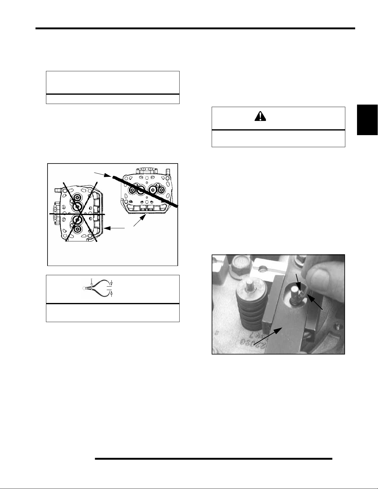
ENGINE
Cylinder Head Inspection
Thoroughly clean cylinder head surface to remove all traces of
gasket material and carbon.
CAUTION
Use care not to damage sealing surface.
Cylinder Head Warp
1. Lay a straight edge (A) across the surface of the cylinder
head (B) at several different points and measure warp by
inserting a feeler gauge between the straight edge and the
cylinder head surface. If warp exceeds the service limit,
replace the cylinder head.
A
Valve Seal / Spring Service (On Engine)
NOTE: The following procedure is only for servicing
the top end of the valve train when replacing valve
springs or replacing valve seals.
In some cases the valve train can be serviced while the cylinder
head is still on the engine. Keep all parts in order with respect
to their location in the cylinder head.
WARNING
3
Wear eye protection or a face shield during
cylinder head disassembly and reassembly.
1. Having already removed the valve cover, rocker arms and
pushrods, align the cylinder to be worked on at top dead
center (TDC). Install the Valve Pressure Hose (PU-
45652) into the spark plug hole. Hook the hose to an air
compressor and supply 50 to 100 psi to the hose. This will
seat the valves during valve spring removal. Do not
remove air from the hose at anytime until reassembly is
completed.
Measure at different
points on the surface.
Cylinder Head Warp Limit:
.004" (.1016 mm) max
B
= In. / mm.
2. Using the Valve Spring Compressor (PU-45257),
compress the valve spring and remove the valve keepers.
NOTE: A small parts magnet (A) can aid in the
removal of the retainers (B).
B
A
PU-45257
NOTE: To prevent damage to the valve seals, do not
compress the valve spring more than is needed to
remove the valve keepers.
3. Remove spring retainer and spring.
4. The valve seals are now serviceable.
3.25
Page 77

ENGINE
Cylinder Head Disassembly
1. Carefully remove the cylinder components.
2. Place the hydraulic lifters (C), pushrods (D), and rocker
arms (E) in a safe, clean area.
C
D
4. Remove valve guide seals.
IMPORTANT: It is recommended to replace seals
whenever the cylinder head is disassembled.
Hardened, cracked or worn valve seals will cause
excessive oil consumption and carbon buildup.
5. Mark the valves with a white pen. Remove the valves from
the cylinder head. This will ensure that the valves are
properly placed during engine reassembly.
Mark the Valves
E
3. Measure free length of spring with a Vernier caliper.
Compare to specifications. Replace spring if measurement
is out of specification.
V alve Spring
Free Length
= In. / mm.
Valve Spring Free Length:
Std: 1.735" (44.069 mm)
3.26
Page 78

Valve Inspection
ENGINE
1. Remove all carbon from valves with a soft wire wheel or
brush.
2. Check valve face for runout, pitting, and burnt spots. To
check for bent valve stems, mount valve in a drill or use “V”
blocks and a dial indicator.
3. Check end of valve stem for flaring, pitting, wear or damage
(A).
= In. / mm.
Valve Stem Diameter:
Intake: 0.2356" + 0.00039"
(5.985 + 0.01 mm)
Exhaust: 0.2351" + 0.00039"
(5.972 + 0.01 mm)
6. Measure valve guide (C) inside diameter at the top middle
and end of the guide using a small hole gauge and a
micrometer. Measure in two directions.
C
3
A
B
4. Inspect split keeper groove for wear or flaring of the keeper
seat area (B).
NOTE: The valves can be re-faced or end ground, if
necessary. They must be replaced if extensively
worn, burnt, bent, or damaged.
5. Measure diameter of valve stem with a micrometer in three
places, then rotate 90 degrees and measure again (six
measurements total). Compare to specifications.
Measure valve stem in several places.
Rotate the valve 90 degrees and measure
for wear.
= In. / mm.
Valve Guide I.D.:
0.23672" + 0.000295"
(6.0617 + 0.0075 mm)
7. Subtract valve stem measurement from the valve guide
measurement to obtain stem to guide clearance. NOTE:
The valve guides cannot be replaced. Be sure to measure
each guide and valve combination individually.
3.27
Page 79

ENGINE
Combustion Chamber
1. Clean all accumulated carbon deposits from combustion
chamber and valve seat area with carbon cleaner and a soft
plastic scraper.
IMPORTANT: Do not use a wire brush, metal scraper,
or abrasive cleaners to clean the bottom of the
cylinder head. Extensive damage to the cylind er head
may result. Wear safety glasses during cleaning.
Combustion Area
NOTE: Valve seat width and point of contact on the
valve face is very important for proper sealing. The
valve must contact the valve seat over the entire
circumference of the seat, and the seat must be the
proper width all the way around. If the seat is
uneven, compression leakage will result. If the seat
is too wide, seat pressure is reduced, causing
carbon accumulation and possible compression
loss. If the seat is too narrow, heat transfer from
valve to seat is reduced. The valve may overheat
and warp, resulting in burnt valves.
Valve Seat Reconditioning
NOTE: Polaris recommends that the work be done
by a local machine shop that specializes in this area.
NOTE: The cylinder head valve guides cannot be
replaced.
WARNING
Wear eye protection or a face shield during
cylinder head disassembly and reassembly.
Valve Seat Inspection
Inspect valve seat in cylinder head for pitting, burnt spots,
roughness, and uneven surface. If any of the above conditions
exist, the valve seat must be reconditioned. If the valve seat is
cracked the cylinder head must be replaced.
Follow the manufacturers instructions provided with the valve
seat cutters in the Cylinder Head Reconditioning Kit (PN
2200634). Abrasive stone seat reconditioning equipment can
also be used. Keep all valves in order with their respective seat.
1. Install pilot into valve guide.
2. Apply cutting oil to valve seat and cutter.
3. Place 46
cutter on the pilot and make a light cut.
3.28
Page 80

ENGINE
4. Inspect the cut area of the seat:
* If the contact area is less than 75% of the circumference of the
seat, rotate the pilot 180
* If the cutter now contacts the uncut portion of the seat, check
the pilot. Look for burrs, nicks, or runout. If the pilot is bent it
must be replaced.
* If the contact area of the cutter is in the same place, the valve
guide is distorted from improper installation
* If the contact area of the initial cut is greater than 75%,
continue to cut the seat until all pits are removed and a new seat
surface is evident. NOTE: Remove only the amount of material
necessary to repair the seat surface.
5. To check the contact area of the seat on the valve face, apply
a thin coating of Prussian Blue paste to the valve seat. If
using an interference angle (46
marker to the entire valve face (A).
and make another light cut.
) apply black permanent
NOTE: When using an interference angle, the seat
contact point on the valve will be very narrow, and is
a normal condition. Look for an even and
continuous contact point all the way around the
valve face (A).
B
A
Proper Seat Contact
on Valve Face
Bottom 60
Seat 45
Top 30
3
A
6. Insert valve into guide and tap valve lightly into place a few
times.
7. Remove valve and check where the Prussian Blue
indicates seat contact on the valve face. The valve seat
should contact the middle of the valve face or slightly
above, and must be the proper width.
* If the indicated seat contact is at the top edge of the valve face
and contacts the margin area (B) it is too high on the valve face.
Use the 30
* If too low, use the 60
area is centered on the valve face, measure seat width.
* If the seat is too wide or uneven, use both top and bottom
cutters to narrow the seat.
* If the seat is too narrow, widen using the 45
check contact point on the valve face and seat width after each
cut.
cutter to lower the valve seat.
cutter to raise the seat. When contact
cutter and re-
Seat
Width
= In. / mm.
Valve Seat Width:
Intake Std: .028" (.7 mm)
Limit: .055" (1.4 mm)
Exhaust Std: .039I (1.0 mm)
Limit: .071" (1.8 mm)
3.29
Page 81

ENGINE
8. Clean all filings from the area with hot soapy water, rinse,
and dry with compressed air.
9. Lubricate the valve guides with clean engine oil, and apply
oil or water based lapping compound to the face of the
valve.
NOTE: Lapping is not required with an interference
angle valve job.
10. Insert the valve into its respective guide and lap using a
lapping tool or a section of fuel line connected to the valve
stem.
Cylinder Head Reassembly
NOTE: Assemble the valves one at a time to
maintain proper order.
1. Apply engine oil to valve guides and seats.
2. Coat valve stem with molybdenum disulfide grease or
0W-40 Synthetic oil.
3. Install valve carefully with a rotating motion to avoid
damaging valve seal.
4. Valve seals should be installed after the valves are in the
head to avoid valve seal damage. Install new valve seals
on valve guides.
5. Dip valve spring and retainer in clean engine oil and install.
6. Place retainer on spring and install Valve Spring
Compressor (PU-45257). Install split keepers with the gap
even on both sides.
NOTE: A small magnet can be used to aid in the
installation of the keepers.
PU-45257
11. Rotate the valve rapidly back and forth until the cut sounds
smooth. Lift the valve slightly off of the seat, rotate 1/4
turn, and repeat the lapping process. Do this four to five
times until the valve is fully seated, and repeat process for
the other valve(s).
12. Thoroughly clean cylinder head and valves.
7. Repeat procedure for remaining valves. When all valves
are installed, tap lightly with soft faced hammer on the end
of the valves to seat the split keepers.
NOTE: To prevent damage to the valve seals, do not
compress the valve spring more than necessary to
install the keepers.
3.30
Page 82

ENGINE
Valve Sealing Test
1. Clean and dry the combustion chamber area (A).
A
2. Pour a small amount of clean solvent onto the intake port
and check for leakage around each intake valve. The valve
seats should hold fluid with no seepage.
3. Repeat for exhaust valves by pouring fluid into exhaust
port.
Cylinder Removal
1. Follow engine disassembly procedures to remove rocker
cover and cylinder head.
2. Tap cylinder (A) lightly with a rubber mallet in the
reinforced areas only until loose.
3. Rock cylinder forward and backward while lifting it from
the crankcase, supporting pistons and connecting rods.
Support pistons with Piston Support Block (PN 2870390).
Valve Lifter Removal / Inspection
1. Remove the valve lifter's by reaching into the crankcase
and pushing the lifter up through the lifter bore by hand.
2. Thoroughly clean the lifters in cleaning solvent and w ipe
them with a clean lint-free cloth.
3. Mark the lifters with a white pen if using the lifters for
reassembly. This will ensure that the lifters are properly
placed during engine reassembly.
Mark Hydraulic Lifter
3
4. Check the lifters for wear or scores.
5. Check the bottom end of lifter to make sure that it has a
slight convex.
6. If the bottom surface has worn flat, it may be used with the
original camshaft only.
A
Inspect Hydraulic Lifter
NOTE: Lifters that are scored, worn, or if the bottom
is not smooth should be replaced with new lifters
and cam as an assembly. If replacing the lifters, the
camshaft should also be replaced.
3.31
Page 83

ENGINE
Piston Removal
1. Remove circlip (A). Mark the piston with a white pen to
ensure proper orientation (if reused) during assembly.
NOTE: If the pistons are to be reused, reassemble
the pistons in the same cylinder and direction from
which they were removed.
NOTE: New pistons are non-directional and can be
placed in either cylinder.
The oil control ring is a three piece design consisting of a top and
bottom steel rail and a center expander section. The top rail has
a locating tab on the end which fits into a notch (B) in the upper
oil ring land of the piston.
To Remove:
A) Remove the top rail first followed by the bottom rail.
B) Remove the expander.
Compression
Rings
Oil Ring
B
2. Remove piston circlip and push piston pin out of piston. If
necessary, heat the crown of the piston slightly with a
propane torch. CAUTION: Do not apply heat to the piston
rings. The ring may lose radial tension.
3. Remove top compression ring:
*Using a piston ring pliers: Carefully expand ring and lift it off
the piston. CAUTION: Do not expand the ring more than the
amount necessary to remove it from the piston, or the ring may
break.
*By hand: Placing both thumbs as shown, spread the ring open
and push up on the opposite side. Do not scratch the ring lands.
4. Repeat procedure for second ring.
5. Remove the oil control ring.
3.32
Page 84

ENGINE
Cylinder Inspection
1. Remove all gasket material from the cylinder sealing
surfaces.
2. Inspect the top of the cylinder (B) for warp using a straight
edge (A) and feeler gauge (C). Refer to Ill. 1 and Ill. 2.
A
B
Measure at different
points on surface.
B
3. Inspect cylinder for wear, scratches, or damage.
3
4. Inspect cylinder for taper and out of round with a
telescoping gauge or a dial bore gauge. Measure in two
different directions, front to back and side to side, on three
different levels (1/2, down from top, in the middle, and 1/
2, up from bottom). Record measurements. If cylinder is
tapered or out of round beyond .002", the cylinder must be
replaced.
1/2” Down From Top of Cylinder
A
C
= In. / mm.
Cylinder Warp: .004" (0.1 mm) Max.
1/2” Up From Bottom
= In. / mm.
Cylinder Taper Limit:
.002" (9.05mm) Max.
Cylinder Out of Round:
Limit: .002" (.0 mm) Max.
700 Standard Bore Size
(Both Cylinders): 3.1496
" (80 mm)
3.33
Page 85

ENGINE
Piston-to-Cylinder Clearance
Measure piston outside diameter at a point 5 mm up from the
bottom of the piston at a right angle to the direction of the piston
pin.
Subtract this measurement from the maximum cylinder
measurement obtained in Step 5.
5 mm
Piston
Piston Pin
Piston to Cylinder Clearance:
See “700 EFI Engine Service
Specifications” on page 3.11
2. Measure piston pin O.D. Replace piston and/or piston pin
if out of tolerance.
Piston Pin Measurement Locations
Piston Pin O.D.:
See “700 EFI Engine Service
Specifications” on page 3.11
3. Measure connecting rod small end ID.
Piston O.D.:
See “700 EFI Engine Service
Specifications” on page 3.11
Piston / Rod Inspection
1. Measure piston pin bore.
Piston Pin Bore:
See “700 EFI Engine Service
Specifications” on page 3.11
Connecting Rod Small End I.D.:
See “700 EFI Engine Service
Specifications” on page 3.11
3.34
Page 86

ENGINE
4. Measure piston ring to groove clearance by placing the ring
in the ring land and measuring with a thickness gauge.
Replace piston and rings if ring-to-groove clearance
exceeds service limits.
Piston
Ring
Feeler Gauge
See “700 EFI Engine Service
Specifications” on page 3.11
Piston Ring Installed Gap
1. Place each piston ring (A) inside cylinder (B) using piston
to push ring squarely into place as shown.
3. If the bottom installed gap measurement exceeds the
service limit, replace the rings. If ring gap is smaller than
the specified limit, file ring ends until gap is within
specified range.
NOTE: Always check piston ring installed gap after
re-boring a cylinder or when installing new rings. A
re-bored cylinder should always be scrubbed
thoroughly with hot soapy water, rinsed, and dried
completely. Wipe cylinder bore with oil immediately
to remove residue and prevent rust.
Starter Drive Bendix Removal / Inspection
1. Remove stator housing bolts and remove housing.
2. Remove the flywheel nut and washer. Install Flywheel
Puller (PN 2871043) and remove flywheel.
NOTE: Do not thread the puller bolts into the
flywheel more than 1/4, or stator coils may be
damaged.
3. Remove starter bendix assembly (A). Note the thrust
washers located on both sides of the bendix.
A
3
C
B
A
25-50 mm
Piston Ring Installed Gap
See “700 EFI Engine Service
Specifications” on page 3.11
NOTE: Ring should be installed with the mark facing
upward.
2. Measure installed gap with a feeler gauge (C) at both the
top and bottom of the cylinder.
IMPORTANT: A difference in end gap indicates
cylinder taper. The cylinder should be measured for
excessive taper and out of round.
4. Inspect the thrust washer for wear or damage and replace
if necessary.
5. After the bendix is removed, remove the two bo lts retaining
the starter. Tap on the starter assembly (B) with a soft faced
mallet to loosen the starter from the crankcase.
B
3.35
Page 87

ENGINE
6. Inspect gear teeth on starter drive (A). Replace starter drive
if gear teeth are cracked, worn, or broken.
7. Inspect the bendix bushing (C) in the mag co ver for wear.
Replace as needed.
C
Flywheel / Stator Removal / Inspection
1. Remove stator housing bolts and remove housing.
2871043
4. Use caution when removing the wir e holddown (B) and the
stator assembly (D). Do not tap or bump the gear /stator
housing cover or the stator. This could cause the seal
around the gear/stator housing cover and the crankcase to
break, causing a leak.
A
Remove Stator
Cover
2. Remove flywheel nut and washer.
3. Install Flywheel Puller (PN 2871043) and remove flywheel
(A).
CAUTION
Do not thread the puller bolts into the flywheel
more than 1/4, or stator coils may be damaged.
E
D
B
5. Remove the bendix (E) if necessary.
Engine Crankcase Disassembly / Inspection
1. Remove the stator cover (A) and water pump cover (B).
B
A
3.36
Page 88

ENGINE
2. Remove the nylok nut (C), washer (D), and water pump
impeller (E). Remove part of the water pump seal behind
the impeller.
E
D
C
3. Remove flywheel nut and washer.
4. Install Flywheel Puller (PN 2871043) and remove flywheel
(F).
CAUTION
5. Remove the starter bendix (G), wire holddown plate (H),
and the woodruff key (I) from the crankshaft. The stator
does not have to be removed at this point.
I
3
G
H
6. Remove the gear/stator housing bolts and remove the gear/
stator housing cover (J) and gasket from the crankcase. Be
sure to catch the excess oil from the crankcase.
Do not thread the puller bolts into the flywheel
more than 1/4, or stator coils may be damaged.
2871043
F
J
7. Note the positions of the gears in the photo.
Camshaft Gear
Crank Gear
Counterbalance Gear
3.37
Page 89

ENGINE
8. Use a white pen to accent the timing marks on the following
gears: camshaft gear (K), crankshaft gear (M), or
counterbalance gear (N) This will ensure proper gear
alignment and timing during reassembly of the gears.
K
Water Pump Gear
Timing Marks
CAUTION
Wear safety glasses at all times. Use caution
when working with the top gear.
The springs could cause injury or become lost
should they pop out.
12. Remove all three springs using one of the tapered pins from
the Tapered Pins (PU-45497-1).
M
N
NOTE: If replacing one of the gears, it is
recommended that all of the gears be replaced. A
gear kit is available in the parts book.
9. Use the Cam Gear Tooth Alignment Tool (PU-45497-2)
(O) to align the cam split gear assembly. With the split gear
aligned, remove the bolt and cam gear assembly.
NOTE: Install the Cam Gear Tooth Alignment Tool
(PU-45497-2) into the assembly hole counter
clockwise from the timing mark as shown.
10. Inspect the cam gear teeth and check to make sure there is
spring tension offsetting the teeth between the two gears.
If there is no tension, check the springs inside of the cam
gear assembly.
3 Loaded Springs
PU-45497-1
13. With a white marking pen, accent the timing mark on the
gear that contains the springs.
11. The cam gear assembly contains three loaded springs. To
open the cam gear assembly:
* Place the cam gear on a flat surface with the timing mark side
facing up.
* While holding both gears together, lightly work a small
flathead screwdriver between the two gears.
* Remove the top gear. The springs should stay in place.
3.38
Accent Timing Marks
Page 90

ENGINE
14. Inspect the gear teeth and the three tabs on the gears for
wear.
Inspect Teeth & Tabs
Replace 3 Springs
15. Install the new springs into the grooves of the cam gear.
Install Springs
To Assemble:
* Hold the spring with one finger.
* Start the pointed end of the tapered pin into the cam gear hole
and slowly push the dowel through the hole until the end of the
dowel is almost flush with the spring.
* Perform this procedure with all three tapered pins.
* Do not push the pins too far through or the springs will pop
out.
NOTE: Do not remove the tapered pins at this time.
3
17. Note in the photograph that the Tapered Pins (PU-45497-
1) are below flush with end of the springs. This helps to
align the three gear tabs during the next step.
16. Insert the pointed dowels from the Tapered Pins (PU-
45497-1) into the cam gear.
PU-45497-1
PU-45497-1
Cam Gear Spring Installation Tool Kit:
(PU-45497)
Tapered Pins:
(PU-45497-1)
Cam Gear Tooth Align Tool:
(PU-45497-2)
18. Line up the two gears using the timing marks and the three
gear tabs that were referenced earlier. Push the gears back
together, using both hands and hold securely.
Align Timing Marks
3.39
Page 91

ENGINE
19. Once the gears are pressed together, firmly hold the gears
together with one hand. Carefully remove the Tapered Pins
(PU-45497-1) by pulling them out one at a time with the
other hand.
20. After the tapered pins are removed, be sure the cam gear
assembly is held together tightly. Place the cam gear
assembly on a flat surface. Use the Cam Gear Tooth
Alignment Tool (PU-45497-2) to align the teeth of the cam
gears, as shown in the picture.
NOTE: Install the Cam Gear Alignment Tool (PU45497-2) into one assembly hole counter clockwise
from the timing mark.
21. To remove the balance shaft gear, the flat side of the
camshaft (P) must face the balance shaft gear. To rotate the
camshaft, use the Cam Spanner Wrench (PU-45498) to
rotate the camshaft so the flat side of the camshaft faces the
balance shaft gear.
PU-45498
P
NOTE: This Cam Spanner Wrench (PU-45498) is
only needed to rotate the camshaft when the entire
valve train is assembled. If the rocker arms are
removed, the cam-shaft can be turned by hand.
22. Remove t he bolt and nut from the balance shaft gear. Try
to remove the balance shaft gear. If the gear does not come
off manually, use the Flywheel Puller (PN 2871043) to
remove the balance shaft gear.
PU-45497-2
NOTE: For ease of installing the Cam Gear
Alignment Tool (PU-45497-2) (R), use a twisting
motion when pushing down on the tool.
2871043
3.40
Page 92
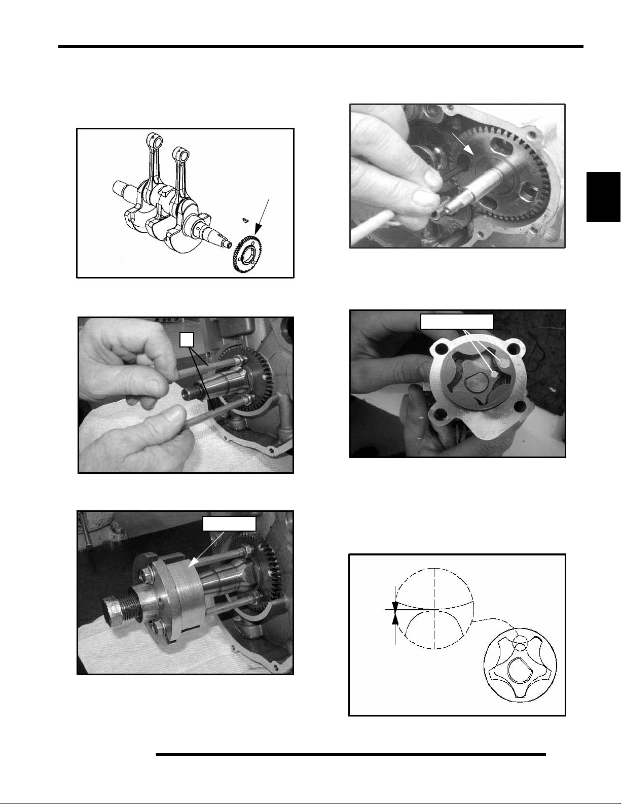
ENGINE
23. Inspect the crankshaft gear (Q) for broken or worn teeth. If
the crankshaft gear does not need to be replaced, it does not
need to be removed. If the crankshaft gear is damaged,
remove the crankshaft gear with the Flywheel Puller
(PN 2871043).
Q
24. Install the two puller bolts (R). Tighten the puller bolts up
so that the bolts are at equal length.
R
26. Rotate the water/oil pump gear (S), so that all four bolts are
visible though the gear. Remove the four bolts with a hex
wrench. Pull out the pump.
S
3
27. Inspect the oil pump rotors for wear. Mark the rotors with
a white pen to ensure upon reassembly that the correct sides
of the rotors are installed and mesh with the same edges as
previously installed.
Mark Rotors
25. Install the Flywheel Puller (PN 2871043) and remove th e
crankshaft gear, if needed.
2871043
NOTE: If replacing the old rotors, new replacement
rotors will fit into the old oil/water pump housing.
28. Use a feeler gauge to measure the clearance between the
two rotors. Measure the gap between the two rotor tips as
shown below. The clearance should not exceed 0.006"
(0.15 mm).
Max Tip Clearance
0.006” (0.15 mm)
3.41
Page 93
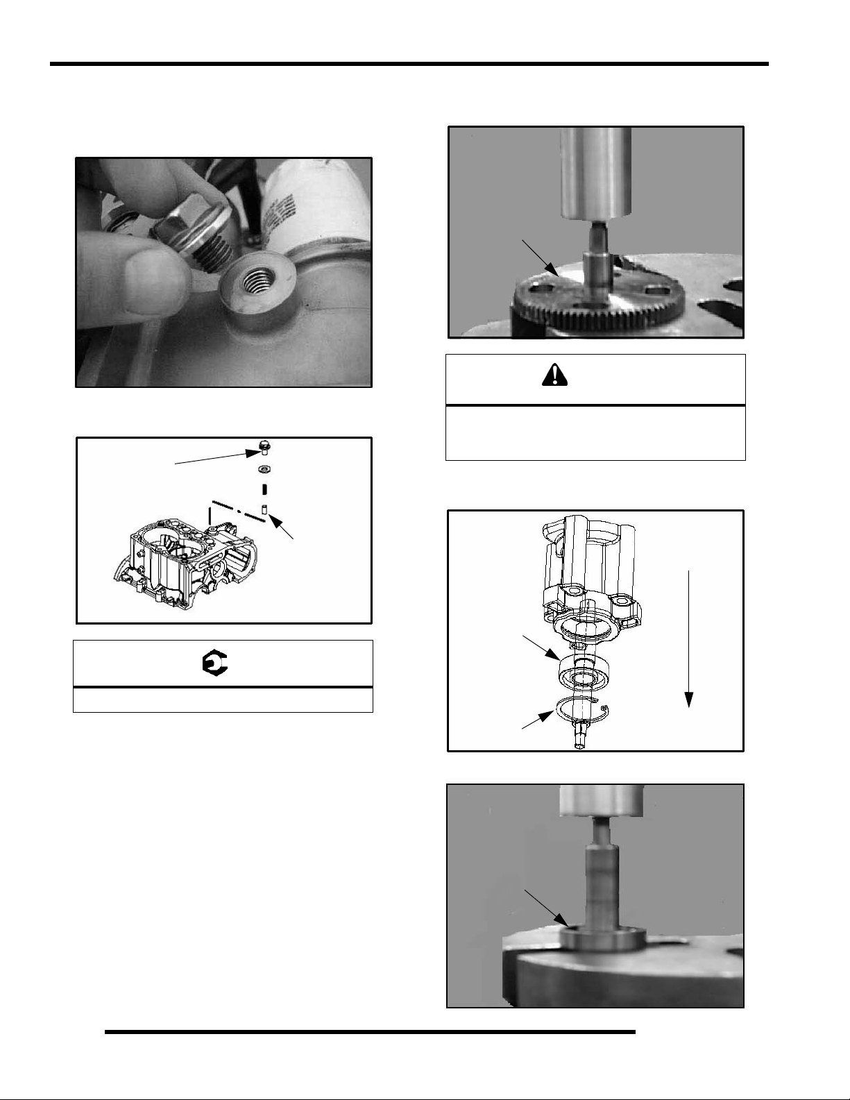
ENGINE
29. Remove the oil pressure relief. The oil pressure relief
consists of a bolt, washer, spring, and valve (dowel).
Inspect the valve (dowel) for signs of possible obstructions.
Use compressed air to blow out any debris.
30. Reinstall the valve (dowel chamfered end first). Install the
spring, washer, and bolt. Torque to specification .
22 ± 2 ft. lbs.
(30 ± 3 Nm).
31. Carefully press the gear off the assembly while supporting
the housing assembly.
Press Off Gear
CAUTION
Wear appropriate safety gear during this
procedure. Protective gloves, clothing and eye
wear are required.
32. Remove the snap ring from the assembly. Place the housing
in a support and press out the bearing/shaft assembly.
Chamfer
End First
= T
22 2 ft. lbs. (30 3 Nm)
NOTE: Be sure to place the tapered en d of the va lve
(dowel) in first. If the valve is installed incorrectly,
oil pressure and oil priming problems will occur.
Press out shaft
and bearing
assembly.
Bearing
Retaining Ring
33. Place the shaft in a press to remove the bearing.
Press Off Bearing
3.42
Page 94

ENGINE
34. Press shaft into the new bearing..
Press On Bearing
35. Press the bearing/shaft assembly using the bearing's outer
race. Do not use the shaft to press the assembly into the
housing, as bearing damage may result. Install retaining
ring.
Press Bearing / Shaft
Assembly using
outer race only
37. Remove thrust plate (U).
U
3
38. Remove PTO end engine mount. Remove crankcase bolts.
Tap on the reinforced areas on the cases using soft hammer.
Carefully separate the two crankcase halves.
Separate
Crankcase Halves
36. Press gear onto shaft while supporti ng the housing.
NOTE: Only remove the oil baffle if the baffle is
damaged. When removing the oil baffle bolts, use a
heat gun to heat the bolts and loosen the Loctite
This will prevent any possible damage to the bolt s or
to the crankcase casting.
39. Remove and clean oil pick up (V) and oil baffle weldment
(W).
.
W
V
3.43
Page 95

ENGINE
40. Remove balance shaft an d crankshaft.
41. Remove and inspect crankshaft main journal bearings for
abnormal wear. It is recommended to replace the
bearings anytime the engine is disassembled.
Camshaft Inspection
1. Thoroughly clean the cam shaft.
2. Visually inspect each cam lobe for wear, chafing or
damage.
3. Measure height of each cam lobe using a micrometer.
Compare to specification.
Cam Lobe Height
= In. / mm.
Cam Lobe Height
(Intake & Exhaust):
Std: 1.3334" (33.8674 mm)
4. Measure camshaft journal outside diameters (O.D.).
C
B
A
= In. / mm.
3.44
Camshaft Journal O.D. :
A. (Mag): 1.654" ± .00039" (42 ± .010 mm)
B. (Ctr.): 1.634" ± .00039" (41.50 ± .010 mm)
C. (PTO): 1.614" ± .00039" (41 ± .010 mm)
Page 96

ENGINE
5. Measure ID of camshaft journal bores.
= In. / mm.
Camshaft Journal Bore I.D.:
(Mag): 1.656" ± 0.00039" (42.07± 0.010 mm)
(Ct r. ) 1.637" ± 0 .0 0039" (4 1. 58 ± 0.010 m m)
(PTO) 1.617" ± 0.00039" (41.07 ± 0.010 mm)
6. Calculate oil clearance by subtracting journal O.D.'s from
journal bore I.D.'s. Compare to specification.
= In. / mm.
Calculated Camshaft Oil Clearance:
Std: 0.0027" (.070mm)
Limit: .0039" (.10 mm)
NOTE: Replace camshaft if damaged or if any part is
worn past the service limit.
NOTE: Replace engine block if camshaft journal
bores are damaged or worn excessively.
1. Install oil pick up (A), if removed. Torque to specification.
B
A
3
2. Install oil baffle weldment (B). Torque bolts to
specification.
= T
Oil Baffle Weldment &
Oil Pick Up Bolt Torque:
60 ± 6 in. lbs. (6.8 ± 0.68 Nm)
3. Install the balance shaft. Inspect balance shaft clearance
(C) in both gearcase halves. Rotate balance shaft to ensure
that there is clearance between it and oil baffle weldment.
ENGINE REASSEMBLY
Crankcase Reassembly
CAUTION
After any reassembly or rebuild, the engine must
be primed using the Oil Priming Adapter (PU-
45778) and a 3/4-full oil filter before initial startup. Follow Steps 45-46 of this section to prime
the engine and to help aid proper break-in.
NOTE: Before assembly, clean the bolts and bolt
holes with Primer N (PN 2870585) to remove any
debris. This will ensure proper sealing when
installing bolts.
C
NOTE: Always install new balance shaft bearings.
3.45
Page 97

ENGINE
4. Apply assembly lube to cam journals and balance shaft
bearing surfaces of the MAG case halve. Install camshaft
and balance shaft.
5. Install crankshaft assembly and apply engine oil to crank
pins and rods (D). Apply assembly lube to the main
journals and bearings.
7. Assemble the crankcase halves. Apply LocTite™ 242 (PN
2871949) to the threads and pipe sealant to the bolt flanges.
Torque bolts to specification following torque pattern at
beginning of this chapter.
= T
Crankcase Bolt Torque:
22 + 2 ft. lbs. (30 + 3 Nm)
Torque in sequence
8. Lubricate cam lobes and valve lifters with Moly Lube
Grease.
Apply Moly Lube
Cam Lobes
D
6. Apply Crankcase Sealant (PN 2871557) to the top gearcase
halve.
NOTE: Do not apply sealant to cam relief hole (E).
E
Lifters
9. Lubricate lifters with engine oil and install in the original
order as removed in disassembly. Apply Lubricant or Moly
Lube to the ends of the lifters.
NOTE: Always repl ace the camshaft and lifters as a
set.
3.46
Page 98

ENGINE
10. Lubricate connecting rods with 0W-40 eng ine oil .
11. Install new cylinder gasket on crankcase. Align gasket on
the dowel pins for proper gasket alignment.
13. Install piston assem blies into cylinder aligning the piston
pin holes, to ensure proper alignment of the pistons to the
connecting rods upon assembly. Partially install the piston
pins into the pistons.
3
NOTE: To help align the pistons, slide a rod that is
close to the same diameter as the wrist pin holes to
properly align them in the cylinder.
14. Position cylinder and piston assemblies onto the connecting
rods and push the piston pins through the piston and
connecting rods.
12. Orientate the pist on rings on the pisto n before installat ion
into the cylinders. Set the gaps of the rings every 120°
(See Illustration Below).
1
Piston Ring
Orientation
1. Top Ring
2. Second Ring
3. Oil Ring
2
3
Push in Piston Pins
15. Install the piston pin circlips. The circlip ends should be
installed at the 12 O'clock position.
Piston Pin Cirlcip in
12 O’clock position
3.47
Page 99

ENGINE
NOTE: While installing in piston circlips, cover all
engine passages. The clip could fall into the engine
during installation.
16. Install cam shaft thrust plate (G) with new bolts. Torque
bolts to specification.
NOTE: New bolts have patch lock on the threads
and do not require Loctite™.
17. Assemble rotors as marked when disassembled. Use a
cleaner to remove the marks previously made on the rotors.
Line Up Marks
18. Appl y assembly lube or oil to the rotors on the oil pump
shaft.
NOTE: The application of lubrication aids in priming
the oil pump during initial engine start up.
Lubricate Rotors
G
= T
Thrust Plate Screw Torque:
115 ± 12 in.lbs. (13 ± 1.35 Nm)
19. Align the bolt holes and install oil pump assembly into
crankcase. Rotate the rotors in the housing during
installation, as this checks for binding if new rotors are
used.
NOTE: For assembly of the gears, the cam gear and
the crankshaft gear are stamped with “This Side
Out." This indicates the side of the gear that faces
outward or away from the case.
3.48
NOTE: Before assembly, clean the bolts and bolt
holes with Primer N (PN 2870585) to remove any
debris. This will ensure proper sealing when
installing bolts and new Loctite™.
Page 100

ENGINE
20. Inst all oil pump housing bolts (H). The new bolts contain
patch lock, so Loctite
Torque bolts to specification and follow the torque
sequence at beginning of the chapter.
is not needed on the new bolts.
H
NOTE: Occasionally spin the oil pump when
installing bolts to check for binding of the rotors.
= T
Oil Pump Bolt Torque:
84 8 in.lbs. (9.50 0.90 Nm)
* Torque in Sequence
21. Apply Loctite 242 (PN 2871949) to the crankshaft.
22. Before installing the crankshaft gear (I), heat the crankshaft
gear to 250 F (121C) on a hot plate (J).
I
J
CAUTION
The crankshaft gear is extremely hot! Severe
burns or injury can occur if the gear is not
handled with extreme care and caution. Follow
the procedure below to help ensure safety.
23. Use extreme caution when removing the crankshaft gear
from the hot plate. Use a pair of pliers and leather gloves
when handling the crankshaft gear.
24. Install the crankshaft gear (I) onto the crankshaft.
NOTE: For assembly of the gears, the cam gear and
the crankshaft gear are stamped with This Side Ou t."
This indicates the side of the gear that fac es outwar d
or away from the case.
3
I
3.49
 Loading...