

Page 1

Page 2

HIGH PERFORMANCE
SERVICE MANUAL
Foreword
This manual is designed primarily for use by Polaris snowmobile service technicians in a properly equipped
shop. Persons using this manual should have a sound knowledge of mechanical theory, tool use, and shop
procedures in order to perform the work safely andcorrectly. The technician should read the text and befamiliar with service procedures before starting the work. Certain procedures require the use of special tools. Use
only the proper tools, as specified. Cleanliness of parts and tools as well as the work area is of primary importance.
All references to left and right side of the vehicle are from the operator’s perspective when seated in a normal
riding position.
This manual includes procedures for maintenance operations, component identification and unit repair, along
with service specifications for the 440 PRO X Fan, 440 PRO X, 600 PRO X, 700 PRO X, 800 PRO X Polaris
snowmobiles. A table of contents is placed at the beginning of each chapter, and an alphabetic index is
provided at the end of the manual for location of specific page numbers and service information. Keep this
manual available for reference in the shop area.
At the time of publication all information contained in this manual was technically correct. However, all
materials and specifications are subject to change without notice.
Comments or suggestions about this manual may be directed to: Polaris Sales Inc., Service Publications
Department, 2100 Hwy 55 Medina, Minnesota 55340.
High Performance Snowmobile Service Manual (PN 9918053)
Copyright 2001 Polaris Sales Inc. Printed in U.S.A.
Page 3

UNDERSTANDING SAFETY LABELS AND INSTRUCTIONS
Throughout these instructions, important information is brought to your attention by the following symbols:
The Safety Alert Symbol means ATTENTION! BECOME ALERT! YOUR SAFETY IS INVOLVED!
DANGER
Failure to follow DANGER instructions will result in severe injury or death to the operator, bystander or person
inspecting or servicing the snowmobile.
WARNING
Failure to follow WARNING instructions could result in severe injury or death to the operator, bystander or
person inspecting or servicing the snowmobile.
CAUTION:
A CAUTION indicates special precautions that must be taken to avoid personal injury, or snowmobile or property damage.
NOTE:
A NOTE provides key information to clarify instructions.
Trademarks
Polaris acknowledges the following products mentioned in this manual:
FLEXLOC, Registered Trademark of SPS Technologies
Loctite, Registered Trademark of the Loctite Corporation
STA-BIL, Registered Trademark of Gold Eagle
FOX, Registered Trademark of Fox Shox
Nyogel, Trademark of Wm. F. Nye Co.
Fluke, Registered Trademark of John Fluke Mfg. Co.
Mity Vac, Registered Trademark of Neward Enterprises, Inc.
Ammco, Registered Trademark of Ammco Tools, Inc.
Torx, Registered Trademark of Textron
Hilliard, Trademark of the Hilliard Corporation
Willwood, Trademark of the Willwood Corporation
Walker Evans Racing Shocks, Trademark of the Walker Evans Ent.
Page 4

Foreword
Welcome to the 2002--2003 Polaris Racing season! Thank you for selecting Polaris as your racing vehicle.
The enclosed technical information, which is based on our past experience, should be reviewed by your team
for machine preparation. Do not feel that these suggestions are a must, but use them as a starting point. This
information has been outlined with reference to the sections in our 2002 Snowmobile Service Manuals. You
will want to refer to them regularly to ensure correct procedures are followed.
The section index enables the user to quickly locate the component unit section desired. A table of contents is
placed at the beginning of each chapter to aid the user in locating general areas of information. Keep this
manual available for reference.
In order to provide you with the best support possible, Polaris racing, engineering, and testing department
personnel must have timely and accurate data from the field. The weekly racing report form is a valuable
source of this data. As a part of the Polaris team, your input is highly valued and
At Polaris, we are committed to your racing effort. We wish you the best of luck in the season ahead!
Please visit our website for updated information throughout the racing season.
never
ignored.
When at the home page (http://www.polarisindustries.com) click on “Snowmobiles” and then “Racing” for
updated infromation throughout the race season.
Race Support Contacts
POLARIS RACING
10303 Calumet Ave.
Suite#3
Mosinee, WI 54455
Phone: (715) 355--5157
Contact: Tom Rager Jr. EXT 11
Bill Rader EXT 12
Fax: (715) 355--8797
Parts Support
Dennis Weinke
Phone: (715) 355--3008
Page 5

Page 6

PRO X Introduction 1.1...................................
Initial Break--In 1.1.......................................
Trail Use Set Up 1.2.....................................
Publication numbers 1.3..................................
Specifications:
440 PRO X Fan 1.4 -- 1.5......................................
440 PRO X 1.6 -- 1.7..........................................
600 PRO X 1.8 -- 1.9..........................................
700 PRO X 1.10 -- 1.11..........................................
800 PRO X 1.12 -- 1.13..........................................
Bolt Size Guide 1.14......................................
Decimal Equivalent Chart 1.15.............................
Conversion Table 1.16....................................
Tap Drill Charts 1.17......................................
Glossary of Terms 1.18--1.21....................................
Tool List 1.22.............................................
Recommended Maintenance Products 1.23..................
Page 7

GENERAL INFORMATION
PRO X Introduction
Polaris’ new Pro X models have been designed and tested to endure the toughest of all races. Many hours, days
and months of testing have gone into development, and engineering has decided to use a predetermined weight
rider and snow cross racing for stock setup. After uncrating your machine, be sure to test ride so setup can be
determined for your
mobile.
1. Stock suspension setup for the PRO X units is geared to a 170 lb (77.18 kg) pro rider.
2. Stock carburetion, clutching and gearing is for 0-3000 ft. (0-900 m).
3. In this manual, there are numerous optional springs, optional carburetor jets, optional clutch weights, and
optional gears to suit your riding preference and location. When changing to optional parts, always test what
you have done. Do not be afraid to experiment.
4. Be sure to use good quality traction products and pattern to maximize your traction and safety.
Break-in
The new PRO X units are high performance snowmobiles, and break-in is a vital step to ensure the performance
of your machine will be at its peak.
riding style and characteristics. The following are setup tips for your brand new Pro X snow-
1. Always break-in any new part for 50-75 miles before using it for racing.
2. Clutch springs and belts need to be broken in to reach their peak in performance.
3. On the 440 Pro X, always use the correct type of fuel for the timing system you are using.
4. Pre mix 20:1 on break in and 32:1 after break in on the 440 Pro X liquid only.
5. Always use the recommended Polaris oil for your snowmobile.
6. Always break-in a new or rebuilt engine to ensure durability.
7. Maintain your exhaust valves frequently to ensure they are operating to their fullest capability.
Two--Cycle Engine Fuel / Oil ratio chart
To figure out the correct fuel to oil ratio per gallon, you will need to use the formula below:
Example of a Fuel/Oil Ratio of 20:1
128 (ounces of fuel in a gallon) y 20 (for the ratio)= 6.4oz. of oil needed for 1 gallon of fuel.
The correct way to mix the oil and fuel together is to have a fuel container 1/2 full of the amount of fuel that you
are wanting to mix. Weigh the oil in a plastic cup to the desired weight ratio, and empty it into the fuel container
and mix. Then empty the remaining fuel into the container and mix thoroughly once more.
Two--Cycle Engine Fuel / Oil Ratio Chart
Gallons of
Engine Fuel
1 6 4
2 13 8
3 19 12
4 26 16
5 32 20
6 38 24
20:1 32:1
1.1
Page 8

GENERAL INFORMATION
ltitude
Below34
C-34t
o-23C-23t
o--12C-12t
o--1
C-1to+10CAbove+10
C
Meter
s
1200180
0
340#3320#3310#3290#2280#2270
(
)
3
0#3300#39
0#20#26
0#25
0
9
0#38
0#20#25
0#20#20
0#26
0#25
0#23
0#20#20
0
Trail Set Up
All 2003 440 Pro X Liquid units that are sold for trail use will need to have Head Kit PN 2202188
installed before the customer rides the sled. This Head Kit is designed to run on Premium 92 octane
non--oxygenated fuel. To keep the warranty valid, this Head Kit must be in place on the 440 Pro
X Liquids that will be sold for trail use. The 440 Pro X Liquid comes stock with a high compression
head that requires 110 Octane fuel. If the head is not changed for Premium 92 octane fuel, engine
damage will occur. Warranty claims will not be accepted for damage that occurs on trail use
2003 440 Pro X Liquid models if this procedure is not performed.
NOTE: Head assembly PN 2202188 is not legal for ISR sanctioned race use.
Parts Required: Kit--92 Octane Cylinder Head PN 2202188
All parts required to perform this installation are included with kit PN
2202188. Parts included are (1) Head PN 3021343, O--ring PNs
5411199, 5411359, 5411411, Rubber Seal PN 5411465, Thermostat
Gasket PN 5830113, and clutch weights for use at 0--3000 ft (3) PN
1321730. Please follow the instructions, clutching, and jetting
recommendations included in the kit.
kit and are not warrantable
.
Please install this Head Kit PN 2202188 on all 440 Pro X Liquid models that will be used for trail riding.
Jets are not included in this
The installation of this kit must be performed by an authorized Polaris dealer.
2003 440 Pro X 92 Octane Jetting Chart
AMBIENT TEMPERATURE
Altitude
Meters
(Feet)
0-- 600
(0-- 2000)
600-- 1200
(2000-- 4000)
1200-- 1800
(4000-- 6000)
1800--2400
(6000--8000)
2400--3000
(8000--10000)
3000--3700
(10000--12000)
Below -3 0qF
Below -3 4qC
380
360
340 320 310 290 280 270
320 300 290 270 260 250
290 280 270 250 240 220
270 260 250 230 220 200
-30_ to --10_F
-34_to -23_C
#4
#4
360
#4
340
#3
-- 1 0 _to +10_ F
-23_ to --12_C
350
#3
330
#3
+10_to +30 _F
-12_to --1 _C
340
#3
320
#3
+30_to +50 _F
-1_to +1 0_C
320
#3
300
#2
Above +50_F
Above +10_C
310
290
#2
#2
#2
#2
#2
#2
1.2
Page 9

Publication Numbers
GENERAL INFORMATION
Model Model No.
440 Pro X Fan S03NX4FS 9917620 9917817 9917818
440 Pro X S03NX4CS 9917619 9917815 9917816
600 Pro X S03NX6ES 9917621 9917819 9917820
700 Pro X S03NX7CS 9917622 9917821 9917822
800 Pro X S03NX8CS 9917623 9917823 9917824
Owner’s Manual
Supplement
Parts
Manual
Parts
Microfiche
2003 Snowmobile Owner ’s Manual (All) - 9917436
2003 Service Manuals
2000--2003 120 XC SP 9918046
Trail Sport
Super Sport, 340 EDGE, 340 Classic, 500, 440 PRO X FAN
Touring
Wide Trak LX, 340 Touring, Sport Touring, Trail Touring, 500 Classic Touring, 600 Classic Touring, 700 Classic
Touring
Frontier
Frontier Classic, Frontier Touring
Trail Luxury
340 Classic EDGE, 500 Classic, 550 Classic, 600 Classic, 700 Classic
Deep Snow
Trail RMK, 600/700/800 RMK, 700/800 SKS
Performance
500 XC, 500/600/700/800 XC SP, 800 XCR
High Performance
440 PRO X FAN, 440, 600, 700, 800 PRO X
Wallcharts 9918054
Track Poster 9918459
9918048
9918047
9918050
9918049
9918051
9918052
9918053
1.3
Page 10

GENERAL INFORMATION
ltitude
Below34
C
34t
o-23C-23t
o--12C-12t
o--1
C-1to+10CAbove+10
C
Meter
s
1200180
0
320/310#3300/290#3290/280#3280/270#2270/260#1270/260
(
)
300/290#3280/270#3270/260#2260/250#2250/240#1250/240
280/270#3260/250#2250/240#2240/230#1230/220#1230/220
60/50#20/3
0#230/
0#20/0#10/0
0#10/0
0
ltitude
Shift
Clutc
h
Clutc
h
Drive
C
haincas
e
d/S
9
Meter
s
0-900
Alm
ond
/
Silve
r
R49
2
1--4174P
d/S
9
900-180
0
Alm
ond
/
Silve
r
R49
2
1--4174P
d/S
9
180
0-270
0
Alm
ond
/
Silve
r
R49
2
1--4174P
d/S
9
270
0-370
0
Alm
ond
/
Silve
r
R49
2
1--4174P
MODEL: 440 PRO X Fan..........
MODEL NUMBER: S03NX4FS.
ENGINE MODEL: EC45PM040..
CARBURETION
Type VM34AL Mikuni................
Main Jet 330 PTO/320 MAG............
Pilot Jet 40.............
Jet Needle 6HEY34--3...........
Needle Jet Q-2(286)...........
Cutaway 3.0............
Air Screw 0.75 Turns...........
Starter Jet 1.5...........
Valve Seat 1.5 Viton...........
Fuel Octane (R+M/2) 87 Non-Oxygenated.
89 Oxygenated
Throttle Gap
Under Cutaway .281s -(7.14mm)......
CLUTCH
Type P-85................
Belt 3211078.................
Belt Width (Projected) 1.438s.
Side Angle (Overall) 28q..
Outside Circumference 46.625s
Center Distance 11.50s......
Shift Weights S--55........
Primary Spring Almond Red.......
Secondary Spring Silver/Blue....
Driven Helix R49 #3.........
Altitude
Meters
(Feet)
JETTING CHART
Below -3 0qF
Below -3 4qC
0-- 600
(0-- 2000)
600-- 1200
(2000-- 4000)
1200-- 1800
(4000-- 6000)
1800--2400
(6000--8000)
2400--3000
(8000--10000)
3000--3700
(10000--12000)
360/350#4340/330#3330/320#3320/310#3310/300#2310/300
340/330#3320/310#3310/300#3300/290#3290/280#2290/280
320/310 300/290 290/280 280/270 270/260 270/260
300/290
280/270
260/250
XXX
#X
CLUTCH CHART
Altitude
Meters
(Feet)
AMBIENT TEMPERATURE
-30_ to --10_F
-34_to -23_C
-
280/270
260/250
240/230
- # refers to the clip position from top of jet needle.
-- 1 0 _to +10_ F
-23_ to --12_C
270/260
250/240
230/220
+10_to +30 _F
-12_to --1 _C
260/250
240/230
220/210
DRIVE DRIVEN
Shift Clutch Clutch Driven
0-900
(0-3000)
900-1800
(3000-6000)
1800-2700
(6000-9000)
2700-3700
(9000-12000)
Weight
S--55 H
S--53 H
10 AL
Spring
Almon
Red
Almon
Red
Almon
Red
Almon
10
Red
Spring
ilver R4
Blue
ilver R4
Blue
ilver R4
Blue
ilver R4
Blue
+30_to +50 _F
-1_to +1 0_C
250/240
230/220
210/200
n
Helix
#-3
#-3
#-4
#-4
Above +50_F
Above +10_C
250/240
230/220
210/200
Chaincase
Gearing
21-- 41 74P
HYVO
21-- 41 74 P
HYVO
21-- 41 74 P
HYVO
21-- 41 74 P
HYVO
#1
#1
#1
#1
#1
#1
ENGINE
Type Fan Cooled Cylinder Reed.......................
Displacement 438 cc...............
Bore 2.579s (65.5mm).......................
Stroke 2.559s (65mm).....................
Piston / Cylinder Clearance 0.0028s - 0.0041s (0.070 - 0.105 mm)...
Piston Marking 4RD..............
Piston Ring Marking 4N.........
Piston Ring End Gap 0.012 - 0.018 (.3 - .45 mm)........
Operating RPMr200 7750 RPM.........
Idle RPMr200 1600 RPM..............
Engagement RPMr300 5300 RPM......
Cylinder Head Torque 18-19 ft.lbs (2.5-2.8 kg-m)........
Cylinder Base Nut Torque 24-28 ft.lbs (3.3-3.9 kg-m)....
Crankcase Torque (8mm) 17-18 ft.lbs (2.2-2.3 kg-m).....
Crankcase Torque (10mm) 23-25 ft.lbs (3.2-3.5 kg-m)...
Flywheel Torque 60-65 ft.lbs (8.3-9 kg-m).............
1.4
Page 11

GENERAL INFORMATION
MODEL: 440 PRO X Fan..........
MODEL NUMBER: S03NX4FS.
ENGINE MODEL: EC45PM040..
ELECTRICAL CAPACITIES
Flywheel I.D. IG3792 Fuel Tank 11.8 Gal. (45.4 L)...... ..........
CDI Marking CU7235 Oil Tank 3.5 Quarts (3.3 L)....... ............
Alternator Output 240 Watts @ 4000 RPM Coolant N / A... ............
Ignition Timing 28q BTDC@3000RPMr1.5q Chaincase Oil 8 oz...... .......
9q BTDC@75000RPMr1.5q
Spark Plug / Gap NGK BR9ES / 0.028” (0.7mm)...
Lights: Head 2 60 High/55 Low......
Tail 2@3 watts........
Brake 18 watts......
Voltage Regulator LR7..
Electric Start N/A.......
SUSPENSION / CHASSIS CHAINCASE
Body Style Pro X Sprockets / Chain 21:41, 74 P HYVO........ ...
Front Suspension Pro X Reverse Option.. ............
IFS Shocks Ryde FXt Brake Pads HayesType 81........ .........
IFS Spring Rate 90/180#/in. Chaincase Center Dist.7.92” (20.12cm.)....
Front Spring Preload 2.8s Thread Adjust Driveshaft Sprockets 2 Drivers.
Front Vertical Travel 9.22s (23.4 cm..) Brake Type Polaris HPB.........
Rear Suspension Pro X...
Rear Travel 13.9s (35.3 cm..)........
Front Track Shock Ryde FX t..
Spring Rate 190#/in.........
Rear Track Shock Ryde FXt IFP Clicker..
Rear Springs .347s /77q......
Track Type 15sx121sx.82s (38.1x307.34x2.08cm..)........
Track Tension
OPTIONAL REAR TORSION SPRINGS
1 1/2” (38mm) slack with 10# (4.54kg) weight 16” (40.64cm..) ahead of rear idler shaft......
440 Pro X Fan Rear Torsion Springs
SOFT (STD) FIRM
.347s(sq.) diameter/77q .347s(sq.) diameter/77q .359s(sq.) diameter/77q
L.H . 7042159-- 067 L.H. 7042101-067 L.H. 7042157--067
R.H. 7042160--067 R.H. 7042102--067 R.H. 7042158--067
1.5
Page 12

GENERAL INFORMATION
ltitude
Below34
C
34t
o-23C-23t
o--12C-12t
o--1
C-1to+10CAbove+10
C
Meter
s
1200180
0
280#3270#3260#3240#2230#2220
(
)
260#3250#3240#2230#2210#2200
0#23
0#20#20#20
0#29
0
3
0#20#20
0#29
0#28
0#20
ltitude
Shift
Clutc
h
Clutc
h
Drive
C
haincas
e
d140
/20
070
/
Meter
s
0-900
Alm
ond
140/200
70/44
19:43
d140
/20
070
/
900-180
0
Alm
ond
140/200
70/44
19:43
d140
/20
070
/
180
0-270
0
Alm
ond
140/200
70/44
19:43
d140
/20062/40
270
0-360
0
Alm
ond
140/200
62/40
19:43
MODEL: 440 PRO X..........
MODEL NUMBER: S03NX4CS.
ENGINE MODEL: S2424--4460PA4C..
CARBURETION
Type TMX-34 Mikuni................
Main Jet 290............
Pilot Jet 35.............
Jet Needle 6GL67--61--3...........
Needle Jet Q-8 (Fixed)...........
Cutaway 2.5............
Air Screw .5 Turns...........
Valve Seat 1.5 Viton...........
Starter Jet 1.5...........
Fuel Octane w/o Ethanol 110 Oct.minimum
Throttle Gap
Under Cutaway .098s(2.5 mm)......
Exhaust Valve Spring Red/White
CLUTCH
Type P--85................
Belt 3211080.................
Belt Width (Projected) 1.438s (34.93mm).
Side Angle (Overall) 28q..
Outside Circumference 46.625” (118.43cm..)
Center Distance 11.5s (305mm)......
Shift Weights S--51H........
Primary Spring Almond/Red.......
Secondary Spring Red/Blue 140/200....
Driven Helix 70/44 -- .46.........
(66/44 -- .46)
Altitude
Meters
(Feet)
JETTING CHART FOR 110 OCTANE
AMBIENT TEMPERATURE
0-- 600
(0-- 2000)
600-- 1200
(2000-- 4000)
1200-- 1800
(4000-- 6000)
1800--2400
(6000--8000)
2400--3000
(8000--10000)
3000--3700
(10000--12000)
Below -3 0qF
Below -3 4qC
XXX
#X
-30_ to --10_F
-
-34_to -23_C
310
#3
300
#3
280 270 260 240 230 220
260 250 240 230 210 200
240 230 220 210 200 190
230 210 200 190 180 170
- # refers to the clip position from top of jet needle.
300
#3
280
#3
-- 1 0 _to +10_ F
-23_ to --12_C
290
#3
270
#3
+10_to +30 _F
-12_to --1 _C
280
#3
260
#3
+30_to +50 _F
-1_to +1 0_C
270
250
Production=290 Main jet for 0_F at 0-- 1000 feet w/110
Octane non--ethanol fuel, the key switch is removed or in
the110 octane position, and the timing curve in position “D”.
CLUTCH CHART
DRIVE DRIVEN
Altitude
Meters
(Feet)
0-900
(0-3000)
900-1800
(3000-6000)
1800-2700
(6000-9000)
2700-3600
(9000-12000)
Shift Clutch Clutch Driven
Weight
S-- 51H
S-- 49H
S-- 47H
S-- 45H
Spring
Almon
Red
Almon
Red
Almon
Red
Almon
Red
Spring
Red/Blue
Red/Blue
Red/Blue
Red/Blue
Helix
.46
.46
.46
.46
44
44
44
#2
#2
n
Above +50_F
Above +10_C
Chaincase
Gearing
19:43
74P
19:43
74P
19:43
74P
19:43
74P
260
#2
240
#2
#2
#2
#2
#2
ENGINE
Type Liquid Cooled Case Reed w/V.E.S........................
Displacement 438 cc...............
Bore 2.598s (66mm).......................
Stroke 2.520s (64mm).....................
Piston / Cylinder Clearance 0.0023s - 0.0037s(0.06 - 0.095mm)...
Service Limit 0.0059s (0.15mm)................
Piston Marking EK2185/28..............
Piston Ring Marking 3021303.........
Piston Ring End Gap .012s-.018s(.30-.45mm)........
Operating RPMr200 8500 RPM.........
Idle RPMr200 1500 RPM..............
Engagement RPMr300 5500 RPM......
Cylinder Head Torque 20-24 ft.lbs(2.8-3.3 kgm)........
Cylinder Base Nut Torque 30-34 ft.lbs(4.15-4.7 kgm)....
Crankcase Torque (8mm) 20-24 ft.lbs(2.8-3.3 kgm).....
Crankcase Torque (10mm) N/A...
Flywheel Torque 90 ft.lbs(12.4 kgm).............
1.6
Page 13

GENERAL INFORMATION
MODEL: 440 PRO X..........
MODEL NUMBER: S03NX4CS.
ENGINE MODEL: S2424--4460PA4C..
ELECTRICAL CAPACITIES
Flywheel I.D. 4010629 Fuel Tank 5 Gal. (18.9 L)...... ..........
CDI Marking 4010861 Oil Tank N/A (PRE MIX 32:1)....... ............
Alternator Output 280 Watts Coolant 4 Quarts (3.78 L)... ............
Ignition Timing 12q BTDC@1750RPM in “D” CurveChaincase Oil 9 oz...... .......
.with pipe sensor unplugged
Spark Plug / Gap Champion RN-57YCC / 0.025” (0.64mm) PN 3070190...
Lights: Head 2 60High/55Low......
Tail 2@2 watts........
Brake 1@17 watts......
Voltage Regulator T1..
Electric Start N/A.......
SUSPENSION / CHASSIS CHAINCASE
Body Style PRO X Sprockets / Chain 19:43--74 P HYVO........ ...
Front Suspension PRO X Reverse N/A.. ............
IFS Shocks Walker Evans Alum IFP Brake Pads Hayes Type 81........ .........
Comp Adjust w/ Res. Chaincase Center Dist.7.92” (20.12cm.)...................
IFS Spring Rate 74/165#/in. Driveshaft Sprockets 2 Drivers-wide.... .
Front Spring Preload 3.75s Thread Adjust Brake Type Hayes.........
Front Vertical Travel 9.22s (23.42 cm.)
Rear Suspension PRO X...
Rear Travel 13.90s (35.31 cm..)........
Front Track Shock Walker Evans Alum IFP..
Comp Adjust w/ Res....................
Spring Rate 160#/in.........
Rear Track Shock Walker Evans Alum IFP..
Comp Adjust w/ Res....................
Rear Springs .347s (sq.) / 77q......
Track Type 14sx121sx1.625s (35.6 x 307.34 x 4.12cm..)........
Track Tension
OPTIONAL REAR TORSION SPRINGS
11/2s (38mm) slack with 10# (4.54kg) weight 16s (40.64cm..) ahead of rear idler shaft......
440 Pro X Rear Torsion Springs
SOFT (STD) FIRM
.347s(sq.) diameter/77q .347s(sq.) diameter/77q .359s(sq.) diameter/77q
L.H 7042159-067 L.H. 7042101-067 L.H. 7042157-067
R.H. 7042160-067 R.H 7042102-067 R.H. 7042158-067
1.7
Page 14

GENERAL INFORMATION
ltitude
Below34
C
34t
o-23C-23t
o--12C-12t
o--1
C-1to+10CAbove+10
C
Meter
s
1200180
0
420#2400#2390#2370#1350#1330
(
)
0
0#2380#2360#13
0#1330#13
0
3
0#2350#1330#13
0#1300#18
0
3
0#1330#13
0#19
0#10#16
0
ltitude
Shift
Clutc
h
Clutc
h
Drive
C
haincas
e
ue/Red/
5
8
/
Meter
s
0-900
DarkBlue/
Red/Dar
k
5
8--42/
2
3-3974P
ue/Red/
5
8
/
900-180
0
DarkBlue/
Red/Dar
k
5
8--42/
2
3-3974P
ue/Red/
5
8
0
/
180
0-270
0
DarkBlue/
Red/Dar
k
5
8--40/
2
2-3974P
ue/Red/
5
8
0
/
270
0-370
0
DarkBlue/
Red/Dar
k
5
8--40/
2
2-4074P
MODEL: 600 PRO X..........
MODEL NUMBER: S03NX6ES.
ENGINE MODEL: S2392--6044PA6E..
CARBURETION
Type TM 38 Mikuni w/TPS................
Main Jet 440............
Pilot Jet 40.............
Jet Needle 9DFH1-60-2...........
Needle Jet P-8...........
Cutaway 2.0............
Air Screw N/A...........
Valve Seat 1.5 Viton...........
Fuel Octane (R+M/2) 87 Non-Oxygenated.
89 OxygenatedKey
Switch Adj.
Throttle Gap
Under Cutaway .079s (2.0mm)......
Pilot Air Jet .9..........
Starter Jet 140...........
Fuel Screw 1.5 Turns..........
Exhaust Valve Spring Green/Yellow.
CLUTCH
Type P-85................
Belt 3211080.................
Belt Width (Projected) 1.438s (36.52mm).
Side Angle (Overall) 28q..
Outside Circumference 46.625s
Center Distance 11.50s......
Shift Weights 10-58........
Primary Spring Dark Blue/White.......
Secondary Spring Red/Dark Blue....
Driven Helix Team 58--42 /.46.........
Altitude
Meters
(Feet)
JETTING CHART
Below -3 0qF
Below -3 4qC
0-- 600
(0-- 2000)
600-- 1200
(2000-- 4000)
1200-- 1800
(4000-- 6000)
1800--2400
(6000--8000)
2400--3000
(8000--10000)
3000--3700
(10000--12000)
XXX
#X
CLUTCH CHART
Altitude
Meters
(Feet)
AMBIENT TEMPERATURE
-30_ to --10_F
-
-34_to -23_C
480
#3
450
#2
420 400 390 370 350 330
400
370
340
- # refers to the clip position from top of jet needle.
0-900
(0-3000)
900-1800
(3000-6000)
1800-2700
(6000-9000)
2700-3700
(9000-12000)
460
#2
430
#2
380
350
330
-- 1 0 _to +10_ F
-23_ to --12_C
440
410
360
330
310
DRIVE DRIVEN
Shift Clutch Clutch Driven
Weight
Dark Bl
10-58
Dark Bl
10-56
Dark Bl
10-54
Dark Bl
10
#2
#2
Spring
White
White
White
White
+10_to +30 _F
-12_to --1 _C
420
#2
400
#2
340
320
290
Spring
Dark
Blue
Dark
Blue
Dark
Blue
Dark
Blue
+30_to +50 _F
-1_to +1 0_C
Helix
400
#2
380
#1
330
300
270
-- 4 2
.46
-- 4 2
.46
-- 4
.46
-- 4
.46
n
Above +50_F
Above +10_C
390
#1
360
#1
#1
320
#1
280
#1
260
#1
Chaincase
Gearing
23-39 74P
HYVO
23-39 74P
HYVO
22-39 74P
HYVO
22-40 74P
HYVO
ENGINE
Type Liquid Cooled Case Reed w/VES.......................
Displacement 593cc Fuel Pump Manuf. N/A............... .....
Bore 3.041s (77.25mm) Fuel Pump Mark N/A....................... .......
Stroke 2.520 (64mm) Oil Pump Manuf. Mikuni..................... .......
Piston / Cylinder Clearance .0045s-.0059s (.11-.15mm) Oil Pump Mark 2540097... ........
Piston Marking 3021308 Cylinder Head Mark 3021320.............. ....
Piston Ring Marking N/A.........
Piston Ring End Gap .014s-.020s (.38-.51mm)........
Head ccs (Uninstalled) N/A.......
Head ccs (Installed) N/A.........
Operating RPMr200 8000.........
Idle RPMr100 1200..............
Engagement RPMr200 4000......
Cylinder Head Torque 20-24 ft.lbs. (28-33 Nm)........
Cylinder Base Nut Torque 30-34 ft.lbs. (41-47 Nm)....
Crankcase Torque (8mm) 20-24 ft.lbs. (28-33 Nm).....
Crankcase Torque (10mm) N/A...
Flywheel Torque 90 ft.lbs. (124 Nm).............
1.8
- Production Setting
Page 15

GENERAL INFORMATION
MODEL: 600 PRO X............
MODEL NUMBER: S03NX6ES...
ENGINE MODEL: S2392--6044PA6E....
ELECTRICAL CAPACITIES
Flywheel I.D. 4010677 Fuel Tank 11.8 gallons (44.7 liters)...... ..........
CDI Marking 4010715 Oil Tank 3.25 quarts (3.1 liters)....... ............
Alternator Output 280 Watts Coolant 4 quarts (3.8 liters)... ............
Ignition Timing 24q BTDC@3500RPMr500 RPM Chaincase Oil 11 fl. oz.(325cc)/..... .......
With TPS unplugged w/Reverse13fl.oz (384cc)
0.1350s
3.430mm
Spark Plug / Gap Champion RN57YCC / 0.025s (0.64mm)...
Voltage Regulator T1..
Electric Start N/A.......
Magneto Pulses 6....
SUSPENSION / CHASSIS CHAINCASE
Body Style PRO Xt Sprockets / Chain 23:39-74P HYVO........ ...
Front Suspension PRO Xt Reverse Option.. ............
IFS Front Shocks Alum IFP Brake Pads Type 81... .........
IFS Spring Rate 90/180#/in. Chaincase Center Dist.7.92s (20.12cm..)....
Front Spring Preload 2.75s Thread Adjust Driveshaft Sprockets 2 Drivers Wide.
Front Vertical Travel 9.22s (23.4cm..) Brake Type Polaris HPB, Liquid Cooled.........
Rear Suspension PRO Xt...
Rear Axle Travel 13.86”(35.2cm..)...
Front Track Shock Ryde FX IFP w/ R/R..
Spring Rate 160#........
Rear Track Shock Ryde Fx IFP R/R (Preload 1.75”)..
Rear Torsion Springs .359s (sq.) / 77q
Track Type 15sx121sx1s (38.1x307.34x2.54cm..)........
Track Tension 3/8s -1/2s (1-1.3 cm..) slack with 10# (4.54kg) weight 16s (40.64cm..) ahead of rear......
idler shaft.
Overall Snowmobile Length 110s (279cm..).................
Overall Snowmobile Height 46s (117cm..).................
Maximum Snowmobile Width 48s (122cm..)...............
OPTIONAL REAR TORSION SPRINGS
SOFT MEDIUM(STD) FIRM
.347s(Sq.) Diameter x 77q .359s(Sq.) Diameter x 77q .405s(Sq.) Diameter x 77q
L.H. 7042101-067 L.H. 7042157--067 L.H.7042240--067
R.H. 7042102-067 R.H. 7042158--067 R.H.7042240--067
1.9
Page 16

GENERAL INFORMATION
ltitude
Below34
C-34t
o-23C-23t
o--12C-12t
o--1
C-1to+10CAbove+10
C
Meter
s
1200180
0
420#3400#3390#3370#2350#2330
(
)
400#3380#3360#2340#2330#2310
3
0#3350#2330#23
0#2300#28
0
3
0#2330#23
0#29
0#20#26
0
ltitude
Shift
Clutc
h
Clutc
h
Drive
C
haincas
e
/
/
6
/
Meter
s
0-900
B
lack/
B
lack/
6
2--42/
2
5--4176P
/
/
6
/
900-180
0
B
lack/
B
lack/
6
2--42/
2
5--4176P
/
/
6
0
/
180
0-270
0
B
lack/
B
lack/
6
2--40/
2
3-3974P
/
/
6
0
/
270
0-370
0
B
lack/
B
lack/
6
2--40/
2
3-3974P
MODEL: 700 PRO X..........
MODEL NUMBER: S03NX7CS.
ENGINE MODEL: S2378--7070PA7C..
CARBURETION
Type TM40 Mikuni................
Main Jet 440............
Pilot Jet 45.............
Jet Needle J8--9DGN5--57--3...........
Needle Jet P-8...........
Cutaway 1.5............
Fuel Screw 2.25 Turns..........
Valve Seat 1.8...........
Fuel Octane (R+M/2) 87 Non-Oxygenated.
89 Oxygenated
Throttle Gap
Under Cutaway .0787s (2.0mm)......
Starter Jet 145...........
Pilot Air Jet N/A..........
Air Screw 1.25
Exhaust Valve Spring Green/Yellow.
CLUTCH
Type P-85................
Belt 3211080.................
Belt Width (Projected) 1.438s (36.52mm).
Side Angle (Overall) 28q..
Outside Circumference 46.625s
Center Distance 11.50s......
Shift Weights 10-62........
Primary Spring Black / Green.......
Secondary Spring Black/Red....
Driven Helix Team 62--42/.46.........
Altitude
Meters
(Feet)
JETTING CHART
Below -3 0qF
Below -3 4qC
0-- 600
(0-- 2000)
600-- 1200
(2000-- 4000)
1200-- 1800
(4000-- 6000)
1800--2400
(6000--8000)
2400--3000
(8000--10000)
3000--3700
(10000--12000)
XXX
#X
CLUTCH CHART
Altitude
Meters
(Feet)
AMBIENT TEMPERATURE
-30_ to --10_F
-34_to -23_C
480
#4
450
#3
420 400 390 370 350 330
400
370
340
- # refers to the clip position from top of jet needle.
0-900
(0-3000)
900-1800
(3000-6000)
1800-2700
(6000-9000)
2700-3700
(9000-12000)
460
#3
430
#3
380
350
330
-- 1 0 _to +10_ F
-23_ to --12_C
440
410
360
330
310
DRIVE DRIVEN
Shift Clutch Clutch Driven
Weight
10-62
10-60
10-58
10-56
#3
#3
Spring
Black
Green
Black
Green
Black
Green
Black
Green
+10_to +30 _F
-12_to --1 _C
420
#3
400
#3
340
320
290
Spring
Black
Red
Black
Red
Black
Red
Black
Red
+30_to +50 _F
-1_to +1 0_C
400
#3
380
#2
330
300
270
n
Helix
2--42
.46
2--42
.46
2--4
.46
2--4
.46
Above +50_F
Above +10_C
Chaincase
Gearing
25-- 41 76P
HYVO
25-- 41 76P
HYVO
23-39 74P
HYVO
23-39 74P
HYVO
390
#2
360
#2
#2
310
#2
280
#2
260
#2
ENGINE
Type Liquid Cooled Case Reed Twin.......................
Displacement 701cc Fuel Pump Manuf. N/A............... .....
Bore 3.1889s (81mm) Fuel Pump Mark N/A....................... .......
Stroke 2.6772s (68mm) Oil Pump Manuf. Mikuni..................... .......
Piston / Cylinder Clearance 0.0047s - 0.0060s (0.12 - 0.15mm) Oil Pump Mark 2540102... ........
Service Limit 0.0060” (0.15mm) Cylinder Head Mark 3021342................ ....
Piston Marking 3021307..............
Piston Ring Marking N/A.........
Piston Ring End Gap .012mm........
Head ccs (Uninstalled) 37cc.......
Head ccs (Installed) 29.5 -- 30.5cc.........
Operating RPMr200 8100 RPM.........
Idle RPMr200 1400 RPM..............
Engagement RPMr200 3500 RPM......
Cylinder Head Torque 18-22 ft.lbs. (25-30 Nm)........
Cylinder Base Nut Torque 30-34 ft.lbs. (41-47 Nm)....
Crankcase Torque (8mm) 20-24 ft.lbs. (28-33 Nm).....
Crankcase Torque (10mm) 26-30 ft.lbs. (36-42 Nm)...
Flywheel Torque 90 ft.lbs. (124 Nm).............
1.10
- Production Setting
Page 17

GENERAL INFORMATION
MODEL: 700 PRO X..........
MODEL NUMBER: S03NX7CS.
ENGINE MODEL: S2378--7070PA7C..
ELECTRICAL CAPACITIES
Flywheel I.D. 4010677 Fuel Tank 11.8 gallons (44.7 liters)...... ..........
CDI Marking 4010749 Oil Tank 3.25 quarts (3.1 liters)....... ............
Alternator Output 280 Watts Coolant 4 quarts (3.8 liters)... ............
Ignition Timing 18q BTDC@2750RPMr1.5q Chaincase Oil 11 fl. oz.(325cc)..... .......
with TPS unplugged.
0.0815”
2.0705mm
Spark Plug / Gap Champion RN57YCC / 0.025s (0.64mm)...
Voltage Regulator T1..
Electric Start N/A.......
Magneto Pulses 6....
SUSPENSION / CHASSIS CHAINCASE
Body Style PRO X Sprockets / Chain 25:41-76 P HYVO........ ...
Front Suspension PRO X Reverse Option.. ............
IFS Shocks Alum IFP/Threaded Brake Pads Type 81........ .........
IFS Spring Rate 90/180#/in. Chaincase Center Dist 7.92s (20.12cm..)....
Front Spring Preload 2.75s Thread Adjust Driveshaft Sprockets 2 Drivers Wide.
Front Vertical Travel 9.22s (23.4cm..) Brake Type Polaris HPB, Liquid Cooled.........
Rear Suspension PRO Xt...
Rear Axle Travel 13.86”(35.2cm..)...
Front Track Shock Ryde FX IFP w/ R/R (Preload 1.75”)..
Spring Rate 160#........
Rear Track Shock Ryde Fx IFP R/R..
Rear Torsion Springs .359s (sq.) / 77q
Track Type 15sx121sx1s (38.1x307.34x2.54cm..)........
Track Tension 3/8s -1/2s (1-1.3 cm..) slack with 10# (4.54kg) weight 16s (40.64cm..) ahead of rear......
idler shaft.
Overall Snowmobile Length 110s (279cm..).................
Overall Snowmobile Height 46s (117cm..).................
Maximum Snowmobile Width 48s (122cm..)...............
OPTIONAL REAR TORSION SPRINGS
SOFT MEDIUM(STD) FIRM
.347s(Sq.) Diameter x 77q .359s(Sq.) Diameter x 77q .405s(Sq.) Diameter x 77q
L.H. 7042101-067 L.H. 7042157--067 L.H.7042240--067
R.H. 7042102-067 R.H. 7042158--067 R.H.7042240--067
1.11
Page 18

GENERAL INFORMATION
ltitude
Below34
C-34t
o-23C-23t
o--12C-12t
o--1
C-1to+10CAbove+10
C
120
0--180
0
430#4410#4400#3380#3360#3340#3(
Feet
)
ltitude
Shift
Clutc
h
Clutc
h
Drive
C
haincas
e
6
6
/
Meter
s
0-900
6
2--46/
2
5-4076P
6
6
/
900-180
0
6
2--46/
2
5-4176P
6
/
180
0-270
0
6
2--44/
2
3-3974P
6
/
270
0-370
0
6
2--44/
2
3-3974P
MODEL: 800 PRO X..........
MODEL NUMBER: S03NX8CS.
ENGINE MODEL: S2398--8070PA8C..
CARBURETION
Type TM 40 Mikuni................
Main Jet 450............
Pilot Jet 45.............
Jet Needle J8--9DGN5--57/4...........
Needle Jet P-8...........
Cutaway 2.0............
Fuel Screw 1.75 Turns Out..........
Valve Seat 1.8...........
Fuel Octane (R+M/2) Key Switch Adj..
91 Premium
89 Regular
Throttle Gap
Under Cutaway .0787s (2.0mm)......
Starter Jet 135...........
Pilot Air Jet N/A..........
Air Screw 1.5...........
Exhaust Valve Spring Pink/Yellow
CLUTCH
Type P-85................
Belt 3211080.................
Belt Width (Projected) 1.438s (36.52mm).
Side Angle (Overall) 28q..
Outside Circumference 46.625s
Center Distance 11.50s......
Shift Weights 10-64........
Primary Spring Black/Green.......
Secondary Spring Black/Red....
Driven Helix Team 62--46/.46.........
Altitude
Meters
JETTING CHART
Below -3 0qF
Below -3 4qC
0-- 600
(0-- 2000)
600-- 1200
(2000-- 4000)
1200-- 1800
(4000-- 6000)
1800--2400
(6000--8000)
2400--3000
(8000--10000)
3000--3700
(10000--12000)
XXX
#X
CLUTCH CHART
Altitude
Meters
(Feet)
AMBIENT TEMPERATURE
-30_ to --10_F
-34_to -23_C
490
#5
460
#4
430 410 400 380 360 340
410
#4 #3 #3 #3 #3 #2
380
#3 #3 #3 #3 #2 #2
350
#3 #3 #3 #2 #2 #2
- # refers to the clip position from top of jet needle.
470
#4
440
#4
390
360
330
-- 1 0 _to +10_ F
-23_ to --12_C
450
#4
420
#4
370
340
320
+10_to +30 _F
-12_to --1 _C
430
#4
410
#3
350
320
300
+30_to +50 _F
-1_to +1 0_C
410
#3
390
#3
330
310
280
Above +50_F
Above +10_C
400
#3
370
#3
320
290
260
DRIVE DRIVEN
Helix
2--4
.46
2--4
.46
2--44
.46
2--44
.46
n
Chaincase
Gearing
25-40 76P
HYVO
25-41 76P
HYVO
23-39 74P
HYVO
23-39 74P
HYVO
0-900
(0-3000)
900-1800
(3000-6000)
1800-2700
(6000-9000)
2700-3700
(9000-12000)
- Production Setting
Shift Clutch Clutch Driven
Weight
10-64 Black/Green Black/Red
10-62 Black/Green Black/Red
10-60 Black/Green Black/Red
10-58 Black/Green Black/Red
Spring
Spring
ENGINE
Type Liquid Cooled Case Reed Twin Fuel Pump Manuf. N/A....................... .....
Displacement 794cc Fuel Pump Mark N/A............... .......
Bore 3.3464s (85mm) Oil Pump Manuf. Mikuni....................... .......
Stroke 2.7559s (70mm) Oil Pump Mark 2540102..................... ........
Piston / Cylinder Clearance 0.006s - 0.0074s (0.15 - 0.188mm) Cylinder Head Mark 3021324... ....
Service Limit 0.0074” (0.188mm)................
Piston Marking 3021184..............
Piston Ring Marking N/A.........
Piston Ring End Gap 0.016s - 0.022s (0.41 - 0.56mm)........
Head ccs (Uninstalled) 45.7r0.5cc.......
Head ccs (Installed) 32.2r0.5cc.........
Operating RPMr200 8000 RPM.........
Idle RPMr200 1400 RPM..............
Engagement RPMr200 3800 RPM......
Cylinder Head Torque 18-22 ft.lbs. (25-30 Nm)........
Cylinder Base Nut Torque 30-34 ft.lbs. (41-47 Nm)....
Crankcase Torque (10mm) 26-30 ft.lbs. (36-41 Nm)...
Flywheel Torque 90 ft.lbs. (124 Nm).............
1.12
Page 19

GENERAL INFORMATION
MODEL: 800 PRO X..........
MODEL NUMBER: S03NX8CS.
ENGINE MODEL: S2398--8070PA8C..
ELECTRICAL CAPACITIES
Flywheel I.D. 4010677 Fuel Tank 11.8 gallons (44.7 liters)...... ..........
CDI Marking 4010750 Oil Tank 3.25 quarts (3.1 liters)....... ............
Alternator Output 280 Watts Coolant 4 quarts (3.8 liters)... ............
Ignition Timing 29q BTDC@3500RPM Chaincase Oil 11/13 fl. oz.(325cc)..... .......
with TPS unplugged
0.2146s
5.4510mm
Spark Plug / Gap Champion RN57YCC / 0.025s (0.64mm)...
Voltage Regulator T1..
Electric Start N/A.......
Magneto Pulses 6....
SUSPENSION / CHASSIS CHAINCASE
Body Style PRO X Sprockets / Chain 25:40-76 P HYVO........ ...
Front Suspension PRO X Reverse Option.. ............
IFS Shocks Alum IFP/Threaded Brake Pads Type 81........ .........
IFS Spring Rate 90/180#/in. Chaincase Center Dist 7.92s (20.12cm..)....
Front Spring Preload 2.75s Thread Adjust Driveshaft Sprockets 2 Drivers Wide.
Front Vertical Travel 9.22s (23.4cm..) Brake Type Polaris HPB, Liquid Cooled.........
Rear Suspension PRO Xt...
Rear Axle Travel 13.86”(35.2cm..)...
Front Track Shock Ryde FX IFP w/ R/R (Preload 1.75”)..
Spring Rate 160#........
Rear Track Shock Ryde Fx IFP R/R..
Rear Torsion Springs .359s (sq.) / 77q
Track Type 15sx121sx1s (38.1x307.34x2.54cm..)........
Track Tension 3/8s -1/2s (1-1.3 cm..) slack with 10# (4.54kg) weight 16s (40.64cm..) ahead of rear......
idler shaft.
Overall Snowmobile Length 110s (279cm..).................
Overall Snowmobile Height 46s (117cm..).................
Maximum Snowmobile Width 48s (122cm..)...............
OPTIONAL REAR TORSION SPRINGS
SOFT MEDIUM(STD) FIRM
.347s(Sq.) Diameter x 77q .359s(Sq.) Diameter x 77q .405s(Sq.) Diameter x 77q
L.H. 7042101-067 L.H. 7042157--067 L.H.7042240--067
R.H. 7042102-067 R.H. 7042158--067 R.H.7042240--067
1.13
Page 20

GENERAL INFORMATION
Bolt Size Threads/In Grade 2 Grade 5 Grade 8
(MM/Thread)
Torque in. lbs.
#10 - 24 27 (3.1) 43 (5.0) 60 (6.9).............. ................ ..............
#10 - 32 31 (3.6) 49 (5.6) 68 (7.8).............. ................ ..............
Torque ft. lbs. (Nm)
1/4 - 20 5 (7) 8 (11) 12 (16).............. .................. ................
1/4 - 28 6 (8) 10 (14) 14 (19).............. .................. ..............
5/16 - 18 11 (15) 17 (23) 25 (35).............. ................ ..............
5/16 - 24 12 (16) 19 (26) 29 (40).............. ................ ..............
3/8 - 16 20 (27) 30 (40) 45 (62).............. ................ ..............
3/8 - 24 23 (32) 35 (48) 50 (69).............. ................ ..............
7/16 - 14 30 (40) 50 (69) 70 (97).............. ................ ..............
7/16 - 20 35 (48) 55 (76) 80 (110).............. ................ ..............
1/2 - 13 50 (69) 75 (104) 110 (152).............. ................ .............
1/2 - 20 55 (76) 90 (124) 120 (166).............. ................ .............
*To convert ft. lbs. to Nm multiply foot pounds by 1.382.
*To convert Nm to ft.lbs. multiply Nm by .7376.
(Nm)
*
1.14
Page 21

1/64 .0156..........................
1/32 .0312 1 mm = .0394s..................... ..................
3/64 .0469..........................
1/16 .0625...............
5/64 .0781 2 mm = .0787s.......................... ..................
3/32 .0938.....................
7/64 .1094 3 mm = .1181s......................... ..................
1/8 . .1250.. ........
9/64 .1406..........................
5/32 .1563 4 mm = .1575s..................... ..................
11/64 .1719.........................
3/16 .1875 5 mm = .1969s............... ..................
13/64 .2031.........................
7/32 .2188.....................
15/64 .2344 6 mm = .2362s......................... ..................
1/4 .25...........
17/64 .2656 7 mm = .2756s......................... ..................
9/32 .2813.....................
19/64 .2969.........................
5/16 .3125 8 mm = .3150s............... ..................
21/64 .3281.........................
11/32 .3438 9 mm = .3543s.................... ..................
23/64 .3594.........................
3/8 .375...........
25/64 .3906 10 mm = .3937s......................... ..................
13/32 .4063....................
27/64 .4219 11 mm = .4331s......................... ..................
7/16 .4375...............
29/64 .4531.........................
15/32 .4688 12 mm = .4724s.................... ..................
31/64 .4844.........................
1/2 .5 13 mm = .5118........... .....................
33/64 .5156.........................
17/32 .5313....................
35/64 .5469 14 mm = .5512s......................... ..................
9/16 .5625...............
37/64 .5781 15 mm = .5906s......................... ..................
19/32 .5938....................
39/64 .6094.........................
5/8 .625 16 mm = .6299s........... ...................
41/64 .6406.........................
21/32 .6563 17 mm = .6693s.................... ..................
43/64 .6719.........................
11/16 .6875..............
45/64 .7031 18 mm = .7087s......................... ..................
23/32 .7188....................
47/64 .7344 19 mm = .7480s......................... ..................
3/4 .75...........
49/64 .7656.........................
25/32 .7813 20 mm = .7874s.................... ..................
51/64 .7969.........................
13/16 .8125 21 mm = .8268s.............. ..................
53/64 .8281.........................
27/32 .8438....................
55/64 .8594 22 mm = .8661s......................... ..................
7/8 .875...........
57/64 .8906 23 mm = .9055s......................... ..................
29/32 .9063....................
59/64 .9219.........................
15/16 .9375 24 mm = .9449s.............. ..................
61/64 .9531.........................
31/32 .9688 25 mm = .9843.................... ..................
63/64 .9844.........................
11.0............
GENERAL INFORMATION
1.15
Page 22

GENERAL INFORMATION
Unit of Measure Multiplied by Converts to
ft. lbs. x12 =in.lbs.
in. lbs. x .0833 = ft. lbs.
ft. lbs. x 1.382 =Nm
in. lbs. x .0115 =kg-m
Nm x .7376 = ft.lbs.
kg-m x 7.233 = ft. lbs.
kg-m x 86.796 =in.lbs.
kg-m x10 =Nm
in. x 25.4 =mm
mm x .03937 =in.
in. x2.54 = cm..
mile (mi.) x1.6 =km
km x .6214 = mile (mi.)
Ounces (oz) x 28.35 = Grams (g)
Grams (g) x 0.035 = Ounces (oz)
lb. x .454 =kg
kg x 2.2046 =lb.
Cubic inches (cu in) x 16.387 = Cubic centimeters (cc)
Cubic centimeters (cc) x 0.061 = Cubic inches (cu in)
Imperial pints (Imp pt) x 0.568 = Liters (l)
Liters (l) x1.76 = Imperial pints (Imp pt)
Imperial quarts (Imp qt) x 1.137 = Liters (l)
Liters (l) x0.88 = Imperial quarts (Imp qt)
Imperial quarts (Imp qt) x 1.201 = US quarts (US qt)
US quarts (US qt) x 0.833 = Imperial quarts (Imp qt)
US quarts (US qt) x 0.946 = Liters (l)
Liters (l) x 1.057 = US quarts (US qt)
US gallons (US gal) x 3.785 =Liters (l)
Liters (l) x 0.264 = US gallons (US gal)
Pounds - force per square inch (psi) x 6.895 = Kilopascals (kPa)
Kilopascals (kPa) x 0.145 = Pounds - force per square inch (psi)
Kilopascals (kPa) x0.01 = Kilograms - force per square cm..
Kilograms - force per square cm.. x 98.1 = Kilopascals (kPa)
qCtoqF: 9 (qC + 40) y 5--40=qF
qFtoqC: 5 (qF + 40) y 9--40=qC
1.16
Page 23

GENERAL INFORMATION
SAE Tap Drill Sizes
Thread Size Drill Size Thread Size Drill Size
#0-80 3/64
#1-64 53
#1-72 53
#2-56 51
#2-64 50
#3-48 5/64
#3-56 45
#4-40 43
#4-48 42
#5-40 38
#5-44 37
#6-32 36
#6-40 33
#8-32 29
#8-36 29
#10-24 24
#10-32 21
#12-24 17
#12-28 4.6mm
1/4-20 7
1/4-28 3
5/16-18 F
5/16-24 I
3/8-16 O
3/8-24 Q
7/16-14 U
7/16-20 25/64
1/2-13 27/64
1/2-20 29/64
9/16-12 31/64
9/16-18 33/64
5/8-11 17/32
5/8-18 37/64
3/4-10 21/32
3/4-16 11/16
7/8-9 49/64
7/8-14 13/16
1-8 7/8
1-12 59/64
1 1/8-7 63/64
1 1/8-12 1 3/64
11/4-7 17/64
1 1/4-12 1 11/64
11/2-6 111/32
1 1/2-12 1 27/64
13/4-5 19/16
1 3/4-12 1 43/64
2-4 1/2 1 25/32
2-12 1 59/64
2 1/4-4 1/2 2 1/32
21/2-4 21/4
23/4-4 21/2
3-4 2 3/4
Metric Tap Drill Sizes
Tap Size Drill Size Decimal Equivalent Nearest Fraction
3x.50
3x.60
4x.70
4x.75
5x.80
5x.90
6 x 1.00
7 x 1.00
8 x 1.00
8 x 1.25
9 x 1.00
9 x 1.25
10 x 1.25
10 x 1.50
11 x 1 .50
12 x 1.50
12 x 1.75
#39
3/32
#30
1/8
#19
#20
#9
16/64
J
17/64
5/16
5/16
11/32
R
3/8
13/32
13/32
0.0995
0.0937
0.1285
0.125
0.166
0.161
0.196
0.234
0.277
0.265
0.3125
0.3125
0.3437
0.339
0.375
0.406
0.406
3/32
3/32
1/8
1/8
11/64
5/32
13/64
15/64
9/32
17/64
5/16
5/16
11/32
11/32
3/8
13/32
13/32
1.17
Page 24

GENERAL INFORMATION
ACV: Alternating current voltage.
Air Gap Spark Test: A good check for ignition voltage and general ignition system condition. Spark should arc 3/8” (1
cm..) minimum from end of high tension lead to ground. Several testers are available commercially.
Alternator: Electrical generator producing alternating current voltage.
Bore: Diameter of cylinder.
BTDC: Before Top Dead Center.
Bump Steer: When skis toe in and toe out through suspension travel.
CDI: Capacitor Discharge Ignition. Ignition system which stores voltage generated by the stator plate exciter coil in a
capacitor or condenser (in CDI box). At the proper moment a voltage generated by the statorplate pulser coil closes an
electronic switch (thermistor) in the CDI box and allows the voltage in the capacitor to discharge into the primary
windings of the ignition coil.
Center Cylinder: On three cylinder engines, the cylinder between Mag and PTO ends.
Center Distance: Distance between center of crankshaft and center of driven clutch shaft.
Chain Pitch: Distance between chain link pins. Polaris measures chain length in number of pitches.
Clutch Buttons: Plastic bushings which transmit rotation of the clutch to the movable sheave in the drive and driven
clutch.
Clutch Offset: Drive and driven clutches are offset so that drive belt will stay nearly straight as it moves along the clutch
face as the engine torques back.
Clutch Weights: Three levers in the drive clutch which relative to their weight, profile and engine RPM cause the drive
clutch to close.
Coil: A winding of wire around an iron core which has the ability to generate an electrical current when a magnetic field
passes through it.
Combustion Chamber: Space between cylinder head and piston dome at TDC.
Compression: Reduction in volume or squeezing of a gas.
Condenser/Capacitor: A storage reservoir for electricity, used in both E.T. and CDI systems.
Crankshaft Run-Out: Run-out or “bend” of crankshaft measured with a dial indicator while crankshaft is supported
between centers on V blocks or resting in lower half of crankcase. Measure at various points especially at PTO.
Maximum allowable run-out is .006” (.02 cm..).
DCV: Direct current voltage.
Detonation: The spontaneous ignition of the unburned fuel/air mixture after normal spark ignition. Piston looks
“hammered” through, rough appearance around hole. Possible causes: 1) too high a compression ratio for the fuel
octane; 2) low octane fuel; 3) over-advanced ignition timing; 4) lean fuel/air mixture.
Dial Bore Gauge: A cylinder measuring instrument which uses a dial indicator. Good for showing taper and
out-of-round in the cylinder bore.
Displacement: The volume of the cylinder displaced by
the piston as it travels from BDC to TDC. The formula is:
Effective Compression Ratio: Compression ratio measured from after the piston closes the exhaust port.
Electrical Open: Open circuit. An electrical circuit which isn’t complete. (i.e. poor connections or broken wire at hi-lo
beam switch resulting in loss of headlights.
Electrical Short: Short circuit. An electrical circuit which is completed before the current reaches the intended
component. (i.e. a bare wire touching the snowmobile chassis under the seat resulting in loss of taillights and brake
lights).
End Seals: Rubber seals at each end of the crankshaft.
Engagement RPM: Engine RPM at which the drive clutch engages to make contact with the drive belt.
E.T. Ignition: Energy Transfer ignition. Generates primary ignition voltage through electro magnetic induction.
2
Bore x Stroke x 3.1416
4
= Displacement in
CCs
1.18
Page 25

GENERAL INFORMATION
Flat Head Bolt: To be used where finished surfaces require a flush fastening unit. Countersunk.
Foot Pound: Ft. lb. A force of one pound at the end of a lever one foot in length, applied in a rotational direction.
g: Gram. Unit of weight in the metric system.
Head Volume: Cylinder head capacity in cc, head removed from engine with spark plug installed.
Heat Exchanger: A device used to transfer heat. Mounted under running boards, they dissipate engine heat to the
atmosphere.
Hex Head Bolt: Standard type of wrench-applied hexagon head, characterized by clean, sharp corners trimmed
to close tolerances. Recommended for general commercial applications.
Hi-Fax: Trademark of Himont Advanced Materials. The special slide material which fits onto the bottom of the
suspension rails.
High Side: Sled pushes or tips up.
High Tension Wire: The heavy insulated wire which carries the high secondary voltage from the coil to the spark plug.
Hole Shot: A term used when machine starts a race from a dead stop.
Holed Piston: Piston in which a hole has formed on the dome. Possible causes: 1) detonation; 2) pre-ignition.
Ignition Coil: A type of transformer which increases voltage in the primary windings (approx. 200V) to a higher voltage
in the secondary windings (approx. 14KV - 32KV) through inductions. Secondary voltage is high enough to arc the air
gap at the spark plug.
Ignition Generating Coil: Exciter coil, primary charge coil. Stator plate coil which generates primary ignition voltage.
CDI system uses one ignition generating coil. Twin cylinder E.T. ignition systems use two ignition generatingcoils. Coil
is mounted at the top of the stator plate.
Inch Pound: In. lb. 12 in. lbs. = 1 ft. lb.
Kg/cm..2: Kilograms per square centimeter. Metric equivalent of PSI.
Keystone Ring: A piston ring with bevel on upper inside surface.
Kilogram/meter: A force of one kilogram at the end of a lever one meter in length, applied in a rotational direction.
Metric equivalent of ft. lbs.
L Ring: A wide face piston ring with an ”L” shaped cross section. Leg of ”L” goes up when installing on piston.
Labyrinth Seal: A pressure type center seal identified by series of grooves and lands. Polaris engines us this type of
seal to separate the cylinders in the crankcase halves.
Left Side: Always referred to based on normal operating position of the driver.
Lighting Coil: Generates voltage for lights, battery charging, etc by electromagnetic induction.
Loose: When the rear of the vehicle slides outward in a turn. The track does not grab sufficiently.
mm: Millimeter. Unit of length in the metric system. 1mm = .040”.
Mag End: Flywheel side of engine.
Magnetic Induction: As a conductor (coil) is moved through a magnetic field, a voltage will be generated in the
windings. This is how mechanical energy in our engines is converted to electrical energy in the lighting coil, ignition
generating coils and trigger coil.
Ohm: The unit of electrical resistance opposing current flow.
Oval Head Screw: Fully specified as ”oval countersunk”, this head is identical to the standard flat head, but
possesses a rounded upper surface for attractiveness of design.
PTO End: Power Take Off drive (clutch side).
Pan Head Screw: Provides a low, large diameter head, but with characteristically high outer edges along the
outer edge ofthe head wheredriving action ismost effective. Slightly different headcontour when supplied with Phillips
Recess. See dotted line.
Piston Clearance: Total distance between piston and cylinder wall.
Piston Erosion: Piston domemelts. Usually occurs at the exhaust port area. Possible causes: 1) lean fuel/air mixture;
2) improper spark plug heat range.
1.19
Page 26

GENERAL INFORMATION
Pre-Ignition: A problem in combustion where the fuel/air mixture is ignited before normal spark ignition. Piston looks
melted at area of damage. Possible causes: 1) too hot a spark plug; 2) spark plug not properly torqued; 3) “glowing”
piece of head gasket, metal burr or carbon in the combustion chamber; 4) lean fuel/air mixture; 5) Incorrect ignition
timing.
Primary Circuit: This circuit isresponsible for the voltagebuild up in the primarywindings of thecoil. Partsof this circuit
include the exciter coil, points and condenser, wires from the stator plate to the small primary winding in the ignition coil.
In the CDI system the parts include the exciter coil, the trigger coil, the wires from stator plate to CDI box and to the low
resistance primary windings in the ignition coil.
Primary Clutch: Drive clutch on engine.
Primary Compression: Pressure built up in the crankcase of a two stroke engine.
psi.: Pounds per square inch.
Pushing: When the front of the vehicle does not steer as much as the driver desires. The skis do not grab sufficiently.
R&R: Remove and replace.
RFI: Radio Frequency Interference. Caused by high voltage from the ignition system. There are special plug caps and
spark plugs to help eliminate this problem. Required in Canada.
RPM: Revolutions Per Minute.
Relay Coils: Electromagnetic device inan EFI system which controls circuit connection with input from another circuit.
Resistance: In the mechanicalsense, friction or load. In the electrical sense, ohms. Both result inenergy conversionto
heat.
Right Side: Always referred to based on normal operating position of the driver.
Round Head Screw:The familiar head most universally used for general application. Good slot depth, ample
underhead bearing surface and finished appearance are characteristic of this head.
Running Time: Ignition timing when fully advanced or at specified RPM.
Secondary Circuit: This circuit consists of the large secondary coil windings, high tension wire and ground through the
spark plug air gap.
Secondary Clutch: Driven clutch on chaincase or jackshaft.
SeizedPiston: Galling of the sides of apiston. Usually there is a transfer of aluminum from the piston onto the cylinder
wall. Possible causes: 1) improper lubrication; 2) excessive temperatures; 3) insufficient piston clearance; 4) stuck
piston rings.
Self Steer: Pulling the machine to the inside of the track.
Spark Plug Reach: Length of threaded portion of spark plug. Polaris uses 3/4” (2 cm..) reach plugs.
Static Timing: Ignition timing when engine is at zero RPM.
Stator Plate: The plate mounted under the flywheel supporting the primary ignition components and lighting coils.
Stroke: The maximum movement of the piston from bottom dead center to top dead center. It is characterized by 180q
of crankshaft rotation.
Surge Tank: The fill tank in the liquid cooling system.
TDC: Top Dead Center. Piston’s most outward travel from crankshaft.
Transfer: The movement of fuel/air from the crankcase to the combustion chamber in a two stroke engine.
Trigger Coil: Pulser coil. Generates the voltage for triggering (closing) the thyristor and timing the spark in CDI
systems. Small coil mounted at the top of the stator plate next to the ignition generating coil.
V Regulator: Voltage regulator. Maintains maximum lighting coil output at approx. 14.5 ACV as engine RPM
increases.
Venturi: An area of air constriction. A venturi is used incarburetors to speedup air flowwhich lowerspressure in venturi
to below atmospheric pressure, causing fuel tobe pushed throughjets, etc., and into the venturi to be mixed with air and
form a combustible air/fuel mixture.
Vol t: The unit of measure for electrical pressure of electromotive force. Measured by a voltmeter in parallel with the
circuit.
Watt: Unit of electrical power. Watts = amperes x volts.
1.20
Page 27
GENERAL INFORMATION
Service
In order to perform service work efficiently and to prevent costly errors, the technician should read the text in this
manual, thoroughly familiarizing him/herself with procedures before beginning. Pictures and illustrations have
been included with the text asan aid. Notes, cautions andwarnings havealso been included for clarification oftext
and safety concerns. However, a knowledge of mechanical theory, tool use and shop procedures is necessary to
perform the service work safely and satisfactorily. Use only genuine Polaris service parts.
Cleanliness of parts and tools as well as the work areais of primary importance. Dirt and foreign matter will act
as an abrasive and cause damageto precision parts. Clean the snowmobile before beginning service. Clean new
parts before installing.
Watch for sharp edges which can cause personal injury, particularly in the area of the tunnel. Protect hands
with gloves when working with sharp components.
If difficulty is encountered in removing or installing a component, look to see if a cause for the difficulty can be
found. If it is necessary to tap the part into place, use a soft face hammer and tap lightly.
Some of the fasteners in the snowmobile were installed with locking agents. Use of impact drivers or
wrenches will help avoid damage to fasteners.
Always follow torque specifications as outlined throughout this manual. Incorrect torquing may lead toserious
machine damage or, as in the case of steering components, can result in injury or death for the rider(s).
If a torquing sequence is indicated for nuts, bolts or screws, start all fasteners in their holes and hand tighten.
Then, following the method and sequence indicated in this manual, tighten evenly to the specified torque value.
When removing nuts, bolts or screws from a part with several fasteners, loosen them all about 1/4 turn before
removing them.
If the condition of any gasket or O-Ring is in question, replace it with a new one. Be sure the mating surfaces
around the gasket are clean and smooth in order to avoid leaks.
Some procedures will require removal of retaining rings or clips. Because removal weakens and deforms
these parts, they should always be replaced with new parts. When installing new retaining rings andclips use care
not to expand or compress them beyond what is required for installation.
Because removal damages seals, replace any oil or grease seals removed with new parts.
Polaris recommends the use of Polaris lubricants and greases, which have been specially formulated for the
top performance and best protection of our machines. In some applications, such as the engine, warranty
coverage may become void if other brands are substituted.
Grease should be cleaned from parts and fresh grease applied before reassembly of components.
Deteriorating grease loses lubricity and may contain abrasive foreign matter.
Whenever removing or reinstalling batteries, care should be taken to avoid the possibility of explosion
resulting in serious burns. Always disconnect the negative (black) cable first and reconnect it last. Battery
electrolyte contains sulfuric acid and is poisonous! Serious burns can result from contact with the skin, eyes or
clothing. ANTIDOTE: External - Flush with water. Internal - Drink large quantities or water or milk. Follow with
milk of magnesia, beaten egg, or vegetable oil. Call physician immediately. Eyes - Flush with water for 15 minutes
and get prompt medical attention.
1.21
Page 28

GENERAL INFORMATION
Tool List
Tool Part Number Description
2870338 Drive Clutch Spider Nut Socket
2870426 P--85 CLutch Offset Alignment Tool 5/8”
8700220 Clutch Compression Tool
PS--45909
2870576 Drive Clutch Bore Tapered Reamer
2870910 Roller Pin Tool
2870974 Jackshaft Installer
2871173 Primary Clutch Compressor
2871296 Jackshaft Installer
2872085 Clutch Puller (3/4--16 x 14mm)
2872401 20mm C--Clip Tool
2872987 Spider Remover/Installer
PS--45259 Gas Fill Tool & Gauge
PS--45259-- 1 Gas Fill Needles (20 Pack)
PS--45260 Lower Retainer Wrench
PS--45261 IFP Positioning/Extraction Tool
PS--45262 Cylinder Head Wrench
PS--45263 Wear Band Tool
PS--45152 THIN Rear Suspension Wrench
PS--45909 High Performance Driven Clutch Compression Tool
PS--45908 T--Handle Walker Evans IFP Tool
PS--45629 Body Clamps for Walker Evans 1 3/4”
2871358 Clutch Holding Fixture
9314177--A Clutch Holding Wrench
PS--45484 Rivet Punch (To remove self--piercing rivets)
PS--45678 Shock Shaft Seal Protector (.51 diameter shock shaft)
2201639 Shock Shaft Seal Protector (.498 diameter shock shaft)
2201640 Shock Shaft Seal Protector (.620 diameter shock shaft)
PU--45485 Exhaust Spring Removal Tool
2874522 Walker Evans Racing Shock Oil (5w)
TEAM Clutch Compression Tool Extensions (To be used with Clutch Com-
pression tool)
1.22
Page 29

GENERAL INFORMATION
Recommended Maintenance Products
ENGINE OIL RETAINING/SEALING PRODUCTS
Part # Description
2871721 Synthetic 2-Cycle Premium Gold Quarts/ 6 2870652 Fuel Stabilizer 16 oz / 12
2871722 Synthetic 2-Cycle Premium Gold Gallon / 4 2872280 Fuel Stabilizer 2.5Gallon/2
2871723 Synthetic 2-Cycle Premium Gold 16 Gallon Drum 2871329 Nyogelt Grease 2oz
2871884 Synthetic 2 Cycle Premium Gold 55 Gallon Drum 2871064 T-9 Metal Protectant each
2871098 Premium 2-Cycle Oil (TC-W3) Quart Cans / 12 2870632 Metal Polish 10 oz / each
2871097 Premium 2-Cycle Oil (TC-W3) Gallon / 6 2871076 Battery Tendert each
2871240 Premium 2-Cycle Oil (TC-W3) 2.5Gallon/2 2870585 Primer N, Aerosol 25 gr / 1
2871566 Premium 2-Cycle Oil (TC-W3) 16 Gallon Drum 2870584 680 Retaining Compound 10cc / each
2871385 Premium 2-Cycle Oil (TC-W3) 30 Gallon Drum 2871949 Threadlock 242 50cc / 10
2871096 Premium 2-Cycle Oil (TC-W3) 55 Gallon Drum 2871950 Threadlock 242 6cc / 12
2872927 VES 2 Cycle Synthetic Oil Quart 2871951 Threadlock 262 50cc / 10
2872925 VES 2 Cycle Synthetic Oil Gallon 2871952 Threadlock 262 6cc / 12
2872924 VES 2 Cycle Synthetic Oil 55 Gallon Drum 2871953 Threadlock 271 6cc / 12
2872607 Nature Oil (TC-W3) Gallon 2871954 Threadlock 271 36cc / 6
2872926 Nature Oil (TC-W3) 55 Gallon Drum 2871955 Instant Adhesive: Prism 401 3cc / 30
MAINTENANCE PRODUCTS 2871956 Pipe Sealant 565 50cc / 6
2872435 Cross Shaft Break-in Lube 8oz/12 2871957 Silicone, Black RTV 3 oz tube / 12
2872436 Cross Shaft Break-in Lube 2.5 Gal / 2 2871958 Silicone, Black RTV 11 oz Cartridge/12
2871326 Carbon Clean Plus 12 oz / 12 2871959 UltraBlueRTV 3.35 oz / 12
2871280 Premium Chaincase Lubricant Quart / 12 2871960 UltraBlueRTV 13 oz Cartridge/12
2870464 Premium Chaincase Lubricant Gallon / 4 2871961 518 Flange Sealant 50cc / 10
2872281 Premium Chaincase Lubricant 2.5Gallon/2 CRANKCASE SEALANTS
2872951 Synthetic Chaincase Lubricant 12 oz. 2871557 3 Bond 1215 5oz
2873105 Synthetic Chaincase Lubricant Quart VALUE PACKS
2873106 Synthetic Chaincase Lubricant Gallon 2871967 Synthetic Lube Value Pack 4/Valuepack
2872952 Synthetic Chaincase Lubricant 2.5 Gallon 2871593 TC-W3 Lube Value Pack 4/Valuepack
2871323 Premium Antifreeze 60/40 Premix Gallon / 6 WAX AND POLISH
2871534 Premium Antifreeze 60/40 Premix Quart / 12 2871589 Revival/Detailing Kit 6 / Kit
2870995 Premium Gas Shock Oil Quart / 6 2871966 Restore polish/scuff remover 12 / 12 oz.
2872279 Premium Gas Shock Oil 2.5Gallon/2 2871965 Reflect Wax Final Finish 12 / 12 oz.
2870990 Premium Brake Fluid DOT-3 12oz / 12 2871964 Renew vinyl rubber protector 12 / 12 oz.
2870791 Premium Fogging Oil (spray) 12/12 oz RACING FUELS
2871517 Premium Fogging Oil (liquid with spout) Quart / 12 2873019 100 Octane 5 Gallon
2871518 Premium Fogging Oil (liquid) Gallon / 6 2872980 100 Octane 16 Gallon Drum
2871312 Grease Gun Kit (All Season) 3oz/4 2872981 100 Octane 55 Gallon Drum
2871322 Premium All Season Grease 24oz / 10 2873019 110 Octane 5 Gallon
2871423 Premium All Season Grease 143oz/ 2872982 110 Octane 16 Gallon Drum
2871460 Premium Starter Grease 2oz/12 2872983 110 Octane 55 Gallon Drum
2871592 Barrel Pump (for 16/30/55 gal. drums) Each
2871285 Flex Spout (fits gal. and 2.5 gal. jugs) 25
2870505 Isopropyl 10 oz / 24
Packaging
(size / quantity)
Part # Description
Packaging
(size/quantity)
1.23
Page 30

Page 31

Improvements and Specifications 2.1................
Torque Specifications 2.2...........................
Spark Plugs 2.2...................................
Torque Patterns 2.3................................
Formulas 2.4 -- 2.5......................................
VES System 2.6 -- 2.8...................................
440Pro X Timing 2.9...............................
440 Pro X Fan Engine Dissassembly 2.10 -- 2.16.............
440 Pro X Fan Engine Assembly 2.17 -- 2.22.................
440/600 Pro X Engine Dissassembly 2.23 -- 2.26.............
440/600 Pro X Engine Assembly 2.27 -- 2.32.................
700/800 Pro X Engine Dissassembly 2.33 -- 2.38.............
700/800 Pro X Engine Assembly 2.38 -- 2.42.................
VES Maintenance/Adjustment 2.43 -- 2.45...................
VES Optional Springs 2.46...........................
General Inspection Procedures 2.47 -- 2.49..................
Crankshaft Truing 2.50 -- 2.51..............................
Crankshaft Indexing 2.52............................
Exhaust Gas Tempurature 2.53.......................
Piston Wash / Spark Plug Color 2.54..................
Cylinder Head Inspection 2.55........................
Piston Inspection/Measurement 2.56..................
Oil Pump Operation/Inspection 2.57 -- 2.59...................
Cooling System Bleeding Procedures 2.60.............
Cooling System Exploded Views 2.61 -- 2.63.................
Troubleshooting 2.64................................
Page 32

Page 33

Improvements for 2003 440 Pro X
1. V--Forcet Reeds
2. Revised carburetion calibration
3. “Dragon” ignition system
ENGINE
V FORCEt REEDS
Pro X Model Specifications
Machine Model Engine Model Cyl.
Disp.
CC’s
440 Pro X Fan EC45PM040 438 65.5 2.579 65 2.559 2 Fan 87*
440 Pro X S2423--4460PA4C 438 66 2.598 64 2.520 2 Liquid 110**
600 Pro X S2392--6044PA6E 593 77.25 3.041 64 2.520 2 Liquid 87*
700 Pro X S2378--7070PA7C 701 81 3.189 68 2.677 2 Liquid 87*
800 Pro X S2398--8070P8C 794 85 3.346 70 2.756 2 Liquid 87*
* Non-oxygenated. Use minimum 89 octane when using oxygenated fuel.
** 110 Octane minimum.
Model Piston/Cylinder
440 Pro X Fan .07-.105 (.0028-.0041s) 7750 1600
440 Pro X .11--.15 (.0044--.0058) 8400 1500
600 Pro X .11-.14 (.0045-.0055s) 8000 1500
700 Pro X .11 (0.0044”) 8100 1400
800 Pro X .15 (0.006”) 8000 1400
Bore
MM
Bore Clearance
+.05 mm
-- . 0 0 m m
(MM / Inch )
Bore
Inches
RPM ¦200
StrokeMMStroke
Engine
Operating
No. of
Inches
Recommended
Idle RPM
Cyl.
Type of
Cooling
Fuel
Octane
(Min.)
2.1
Page 34

ENGINE
When tightening bolts, nuts, or screws, a torque pattern should be followed to insure uniform equal tension is
applied to all fasteners. Proper torque application prevents fasteners from looseningor breaking in criticalservice.
It also minimizes wear and eliminates premature or needless repair costs. Following uniform torque application
sequence patterns assures optimum performance from precision machined, close tolerance assemblies. On vital
engine parts, torquing negligence could be costly.
Torque is a force which tends to produce rotation. Themeasurement of this force isexpressed in units of force and
length. There are at present two basic systemsof units used to express torque, English and Metric. In the English
system, the units of force are the pound or ounce, and the length is the foot or inch.
In the Metric system, the unit of force is expressed in grams (gm) or Newton meters (Nm), and length as
centimeters (cm.) or meters (m). The most common units of torque in the English system are ft. lb. and in. lb. In
the Metric system, torque is commonly expressed in units of Nm. Multiply foot pounds by 1.382 to obtain Nm.
See page 2.3 for engine torque sequences
Engine
EC-45 18-19 ft. lbs.
S44**
SN60-44**
SN50**
SN60-70**
SN70**
SN80**
**Torque head bolts prior to torquing cylinder base nuts. Apply loctitet 242.
All 6mm Crankcase Bolts 108 in. lbs. (12.4 Nm).....
All 7/16-14 Engine Mount Strap Bolts 44-48 ft. lbs. (60-66 Nm).....
Cylinder Head* Cylinder
(25-26.5 Nm)
20-24 ft. lbs.
(28 - 33 Nm)
18-22 ft. lbs.
(25 - 30 Nm)
Base Nuts
24-28 ft. lbs.
(33-39 Nm)
30-34 ft.lbs
(42-47 Nm)
30-34 ft.lbs
(42-47 Nm)
Crankcase
8mm
17-18 ft. lbs.
(22-23 Nm)
20-24 ft.lbs.
(28 - 33 Nm)
20-24 ft.lbs.
(28 - 33 Nm)
Spark Plugs
Polaris Part
Number
3070156 NGK BR8ES
3070157 NGK BR7ES
3070160 NGK B7ES
3070161 NGK B8ES
3070162 NGK B9ES
3070163 NGK BR9ES
3070165 Champion RN2C
3070166 Champion RN3C
3070184 Champion RN57YC
3070190 Champion RN57YCC
3070198 NGK BR8EV
Spark Plug
Crankcase
10 mm
23-25 ft. lbs.
(32-35 Nm)
N/A
26-30 Ft lbs
(36-42 Nm)
Flywheel
60-65 ft. lbs.
(83-90 Nm)
90 ft. lbs.
(124 Nm)
90 ft. lbs.
(124 Nm)
2.2
Page 35

ENGINE
5
9
10
1
2
6 7
CYLINDER HEAD
440/600 Pro X
5
3
1
8
4
3
15
2
4
6
12
11
5
9
11
7
CRANKCASE - 440/600 Pro X
1 4
3
2
3
7
8
6
5
1
CYLINDER BASE
440/600 Pro X
12
14
10
13
5
9
12
1
4
8
6
2
3
2
4
8
7
11
10
6
CYLINDER HEAD - Pro X Fan
CYLINDER HEAD
Libertyt 700 / 800
5
10
9
1
6
2
CYLINDER BASE
Libertyt 700/800
3
7
5
1
4
3
7
6
2
8
11
CRANKCASE - Pro X
Fan
12
Libertyt Crankcase - 700 / 800
4
8
5
6
1
2
3
4
2.3
Page 36

ENGINE
R = (IHV+DISP)
IHV
I= S
(DISP*25.4)
DISP = (PI*B*B*S)
4
IHV = INSTALLED HEAD VOLUME [CC]
DISP= CYLINDER DISPLACEMENT [CC]
R = COMPRESSION RATIO
S = FULL ENGINE STROKE [CM]
I = INCHES PER CC OF IHV
B = CYLINDER BORE [CM]
PI = 3.1416
Bore = 6.5 cm. Stroke = 6.0 cm. IHV = 17.1 cc
Displacement = SBore Stroke
S
Displacement = 199.098 cc
IHV + Displacement
R=
R = 12.643
IHV
Full Stroke Compression Ratio
To calculate the Effective Compression Ratio, substitute the exhaust port height for the stroke in the
formulas above:
Exhaust = 2.95 cm.
Eff Disp = SBore Stroke
Exhaust port height 29.5 mm
Effective Displacement
Eff Disp = 97.89 cc
Eff Comp =
IHV + Eff Disp
IHV
Effective Compression Ratio
Eff Comp = 6.725
In order to increase the Full Stroke Compression Ratio to 13.6, how much material do you need to
remove from the cylinder head?
You know that:
R=
IHV + Displacement
IHV
, and you want to find out IHV.
Displacement = 199.098 cc, and we want R = 13.6, so then
IHV2 =
IHV2 = 15.801 cc desired IHV to have 13.6:1 Full Stroke Compression Ratio
2.4
Displacement
(R -- 1)
Page 37

HEAD CC REMOVAL EXAMPLE
Total number of CCs to remove from the head = Old IHV -- Desired IHV
Removed CCs = IHV -- IHV2
Removed CCs = 1.299 cc
ENGINE
I=
Displacement ô 2.54 ô
I = 0.01186 ô
To find out how much to cut off, multiply the number of CCs you need to remove
by the number of inches to remove per CC:
Thickness to remove = I ô Removed CCs
Thickness to remove = 0.015 in
PORT OPENING DURATION
Port open = 81.5q
Stroke
Number of inches to remove from the
cm.
in
in
cc
This indicates the degrees after TDC that the exhaust port
opens (and also the degrees before TDC that the port
closes).
cylinder head to equal 1 cc
Duration closed = 2 ô Port open
Duration closed = 163q
Total duration = 360q
Duration open = Total duration -- Duration closed
Duration open = 197q
Percent open =
Percent open = 54.722
Duration open
Total duration
ô 100
2.5
Page 38

ENGINE
Variable Exhaust System (V.E.S.)
Some snowmobiles are equipped with the Polaris
This unique exhaust valve management system changes the effective exhaust port height in the cylinder to provide maximum horsepower at high RPM without sacrificing fuel economy and engine torque at low to midrange
throttle settings.
Variable Exhaust System (V.E.S.)
Spring
Cover
Bellows
Housing
Exhaust Valve
In order to understand the operation and function of the V.E.S. we must first consider the characteristics of a two
stroke engine. The height of the exhaust port in a two stroke enginecylinder has an affect on the total power output
of an engine, as well as the RPM at which the power occurs.
Exhaust systems are “tuned” by design to match engine exhaust port configuration and desired power delivery
characteristics. Engines with relatively “high” exhaust ports (and exhaust pipe to match) produce more horsepower at high RPM, but only at the expense of low to midrange fuel economy and torque. On the other hand,
“low” port engines provide good fuel economy in the midrange and make their power at relatively lower RPM, but
will not produce as much peak horsepower for a given displacement range. In general, an engine designed for
a racing or high performance snowmobile will have a relatively high exhaust port compared to an engine of the
same displacement range designed for touring.
Although the V.E.S. does not in itself increase horsepower, it does allow an engine to be designed for maximum horsepower without the inherent disadvantages of a high exhaust port.
The main components of the V.E.S. are the exhaust valve, valve housing, bellows, return spring, and cover.
A guillotine style exhaust valve is connected to a moveable piston. This piston is attached to a flexible bellows,
forming two chambers. The lower chamber is connected to the cylinder by a drilled passageway located just above
the exhaust port. The upper chamber is vented to atmospheric pressure. A valve return spring is located in the
upper chamber between the piston and cover.
At idle and low speeds, the exhaust valve is held in the “low port” position by the return spring. When throttle is
applied (and RPM begins to increase) rising cylinder pressure is applied to the under side of the bellows via the
actuation port. This forces the exhaust valve upward against spring pressure. The valve continues to move upward toward the “High Port” position as cylinder pressure, horsepower, and RPM increase.
2.6
Page 39

V.E.S. Maintenance
Due to the simplicity of V.E.S. design, maintenance is limited to a periodic inspection and cleaning of system components. The V.E.S. should be disassembled, inspected, and
cleaned (remove carbon deposits) every 1000 to 2000
miles, depending on operating conditions. To ensure maximum performance and minimize required maintenance,
Polaris recommends the use of Polaris Synthetic 2 Cycle
lubricant only. The use of other lubricants may cause improper function of the valve mechanism, and increase the
frequency of required cleaning due to excessive buildup of
carbon deposits.
V.E.S. Removal and Cleaning
Removal and cleaning is covered later in this chapter.
V.E.S. Troubleshooting
Symptom Possible Cause Remedy
Engine will not reach
designed operating RPM
Poor acceleration;
hesitation; High RPM
performance is normal or
near normal
Valve not opening or not opening completely:
1. Exhaust valve sticking
2. Cylinder pressure feed port
restricted
3. Bellows damaged or not sealing
correctly
4. Incorrect spring
5. Problem in clutch setup, drive
line, engine, etc.
Valve opening too early:
1. Valve sticking open or partially
open
2. Broken, damaged, or incorrect,
spring
Valve cover
Bellows
Washer
ENGINE
Adjuster nut
O-ring
Spring
Val ve cap
Bolt
Valve housing
Dowel pin
Gasket
Val ve
1. Remove carbon deposits,
burrs etc.
2. Clean port
3. Inspect bellows, fastener
straps, and gasket and
repair as required
4. Inspect
5. Inspect
1. Clean, Inspect
2. Inspect, Replace
2.7
Page 40

ENGINE
Variable Exhaust System (V.E.S.) - 440 Pro X
440 Pro X Variable Exhaust System:
The exhaust valve system on the new 440 Pro X is electronically controlled by solenoids. Pressure from
the cylinders is routed through the solenoids to the atmosphere. During this time the exhaust valves are
down. When the CDI senses 6700 RPM, it triggers the solenoids to shut off the bypassed air going to the
atmosphere. Pressure then builds inside the exhaust valve bellows, causing the valves to fully open.
When RPM drops below 6700, the solenoids open to allow air to bypass through to atmosphere and the
exhaust valves close.
Solenoid
Open
T-Fitting
Inlet Hole
from Cylinder
Below 6700 RPM
CDI Box
Wire Wire
Hose
Balance Tube
Spring
Bellows
Exhaust Valves Closed
Yellow Wire to
Wiring Harness
Inlet Hole
from Cylinder
Hose
T-Fitting
Spring
Solenoid
Open
Bellows
Above 6700 RPM
Solenoid
Closed
Hose
T-Fitting
Inlet Hole
from Cylinder
CDI Box
Wire
Spring
Bellows
Exhaust Valves Fully Open
Yellow Wire to
Wiring Harness
Wire
Balance Tube
Inlet Hole
from Cylinder
Solenoid
Closed
Hose
T-Fitting
Spring
Bellows
Exhaust
Outlet Hole
Val ve
2.8
Exhaust
Val ve
Exhaust
Val ve
Outlet Hole
Exhaust
Val ve
Page 41

ENGINE
Changing the Timing curve
CAUTION
This engine is jetted for operation at 0 degrees _F and warmer. Re-jetting is required for temperatures colder than 0_F.
The second switch islocated on the airbox andhas seven optionalcurves. These seven options are used tomatch
the fuel type and the racing conditions which may vary, depending on the race. The standard position is “D” and
should not be moved unless you are a knowledgeable engine tuner.
Position
A +3
B +2
C +1
D (Standard Position) 0
E -- 2
F -- 3
G -- 4
Timing Effect
2.9
Page 42

ENGINE
Engine Disassembly - 440 Pro X Fan Engine
NOTE: Inspect all parts for wear or damage during disassembly. Replace all seals, O-rings,
and gaskets with Genuine Polaris parts during assembly.
Disassembly
1. Remove coil pack from air box, and
disconnect it from the wiring harness.
2. Loosen carburetor clamps and remove each
carburetor.
3. Using a pliers, detach the oil lines from the
carburetors.
2.10
Page 43
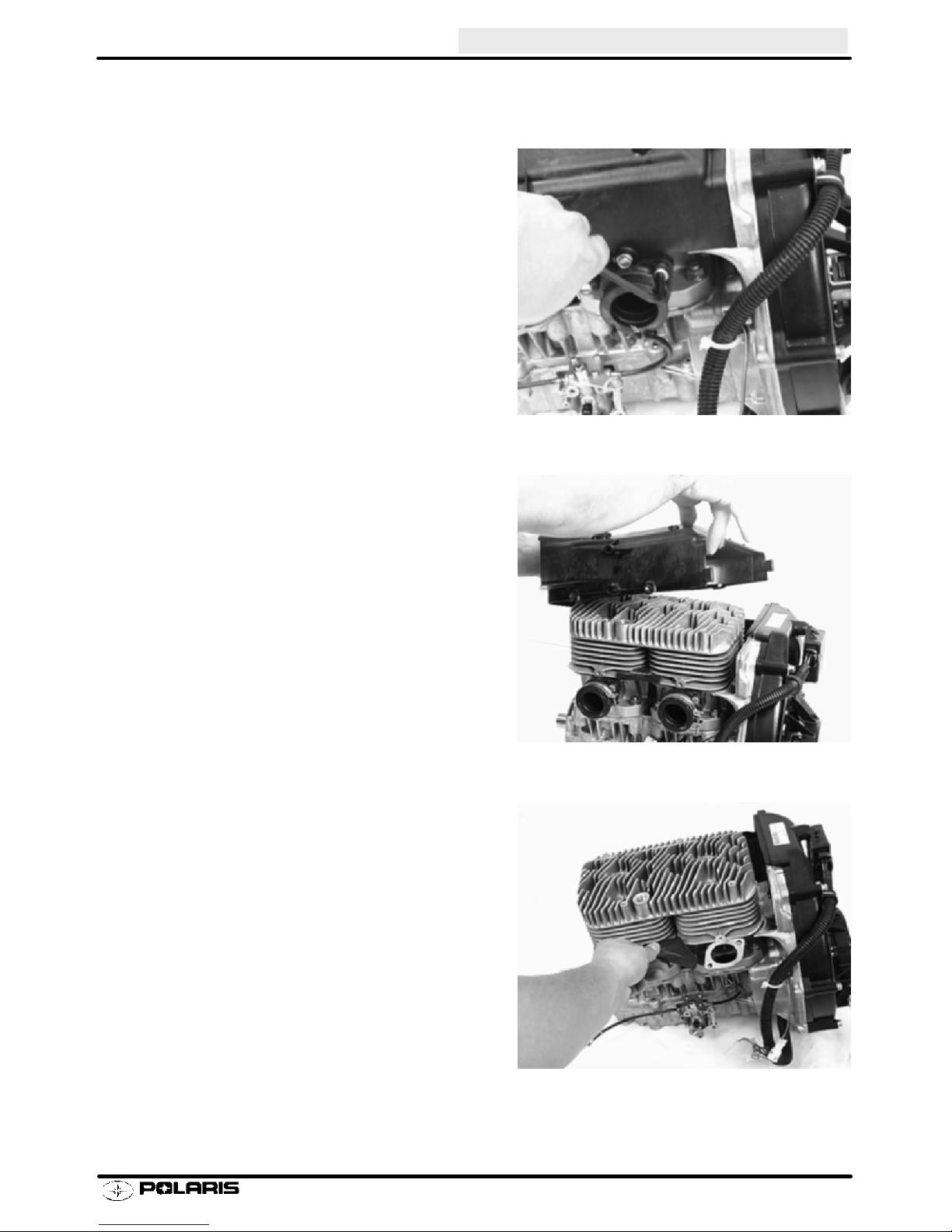
Disassembly - Continued
4. Remove the carburetor mounting boots using
a allen wrench.
ENGINE
5. Remove both the cylinder head and exhaust
side fan shroud s from the engine assembly.
6. After removing the fan shrouds, take note of
the vibration dampener located between the
two intake ports.
2.11
Page 44

ENGINE
Disassembly - Continued
7. Remove the CDI module from the flywheel
cover.
8. Remove the flywheel cover.
9. Prior to removing the flywheel, insert a piece
of nylon rope or cord into a spark plug hole.
Rotate the crankshaft counter-clockwise until
it will no longer turn over.
2.12
Page 45

Disassembly - Continued
10. Remove the recoil cam.
11. Loosen and remove the flywheel nut.
ENGINE
12. Using a flywheel puller, remove the flywheel
from the engine. Do not install puller bolts
more than 5/16s (7mm) into flywheel threads
or stator damage may result.
Flywheel Puller
PN 2871043
2.13
Page 46

ENGINE
Disassembly - Continued
13. Remove the flywheel.
14. The stator plate can be removed without
taking off the stator.
15. Remove the oil pump taking note of the o-ring
and shim(s).
2.14
Page 47

Disassembly - Continued
16. Remove the cylinder head.
17. Remove the head gasket. During removal,
note that the head gasket is stamped with
“EX” and “UP”.
ENGINE
18. Loosen and remove each cylinder.
2.15
Page 48

ENGINE
Disassembly - Continued
19. Remove the reed valves from the crankcase.
20. Using an awl and piston pin puller, remove the
pistons.
CAUTION:
Wear eye protection during piston c-clip removal
to prevent eye injury.
Piston Pin Puller
PN 2870386
21. Turn crankcase over and remove the
crankcase bolts. Turn over and separate the
case halves.
22. Refer to General Inspection section for
crankshaft inspection and measurement
procedures.
2.16
Page 49

Engine Assembly
1. Prior to assembly, make sure that you have all
of the oil pump shims when the oil pump was
removed, and that the shims are installed in
the correct order.
ENGINE
2. Insert oil pump drive gear.
3. Insert oil pump driveshaft spacer.
4.
2.17
Page 50

ENGINE
Engine Assembly - Continued
5. Lay crankshaft into the lower case half. Make
sure that the crankshaft rotates smoothly and
does not bind. Rotate the bearings so that the
anti-rotation pins rest in their appropriate
galleries.
NOTE: Lubricate the crankseal prior to installation.
6. Apply 3-Bond¥ sealer to top half of
crankcase. Lubricate oil pump drive gear.
3-Bond ¥ 1215
PN 2871557 120 Gram Tube
7. Install the upper case half.
8. Turn the crankcase over and torque the case
bolts in sequence illustrated in beginning of
chapter.
Crankcase Bolt Torque
16.6 - 18 ft.lbs. (22 - 25 Nm)
2.18
Page 51

Engine Assembly - Continued
9. Install pistons with arrow (") on piston facing
flywheel, with locating pins to intake side.
Install C-clips securely in piston groove.
NOTE: C--Clip should be facing with the open end up.
10. Lubricate rings and pistons with two stroke oil.
Install rings with letter, mark, or beveled side
facing upward.
ENGINE
11. Install the reed valves in the crankcase. After
installing the reed valves, insert the base
gaskets.
12. Install each cylinder. Torque cylinder base
nuts in sequence illustrated in beginning of
chapter.
Cylinder Base Nut Torque
24 - 28 ft.lbs. (33 - 39 Nm)
2.19
Page 52

ENGINE
Engine Assembly - Continued
13. Install the cylinder head gasket with the “EX”
on the exhaust side, and “UP” on the intake
side of the engine.
14. Insert the dowels into the flywheel housing.
NOTE: Refer to picture for proper installation of
alignment dowels.
15. Tighten flywheel housing to crankcase.
2.20
Page 53

Engine Assembly - Continued
16. Install the flywheel and insert the lock washer.
17. Torque the flywheel nut. During the
procedure, use a flywheel holding wrench to
prevent the flywheel from rotating.
ENGINE
Flywheel Holding WrenchPN 8700229
Flywheel Nut Torque
60 - 65 ft.lbs. (83 - 90 Nm)
18. Reinstall the flywheel cover.
2.21
Page 54

ENGINE
Engine Assembly - Continued
19. Insert the vibration dampener into the cooling
fins between the intake ports. Reinstall the
two fan shrouds making sure that they
interlock before fastening tightly.
20. Using a new o-ring, reinstall the oil pump.
Oil Pump Mounting Screw Torque:
48 - 72 in.lbs. (5.5 - 8.3 Nm)
21. Install each carburetor and torque the
carburetor mounting clamps Reinstall oil lines
on the oil pump.
2.22
Page 55

ENGINE
NOTE: Inspect all parts for wear or damage during disassembly. Replace all seals, O-rings,
and gaskets with Genuine Polaris parts during assembly.
Disassembly -- Liberty t 440 / 600 Liquid
1. Remove carburetor mount adaptors, reed cages,
stuffers, and oil pump. Note position of stator wire
guide.
Measure air gap between fiber reed and reed block
as shown. The air gap should not exceed .015s (.4
mm). If clearance is excessive DO NOT attempt to
reverse the reeds to reduce the air gap.
replace them if damaged.
white stress marks or missing material. Replace if
necessary.
2. Remove V.E.S. (if applicable).
Check eachfiber reedfor
Always
Reed Pedal
Clearance .015s
(.38 mm) max.
Exaggerated
for illustration
3. Remove cylinder head cover and inspect O-rings
and sealing surfaces for damage or debris. Use
new O-rings upon assembly.
2.23
Page 56

ENGINE
Disassembly, Cont.
4. Remove cylinder base nuts. Note location of acorn
nuts on exhaust side (where applicable).
5. Carefully remove cylinders while supporting pistons
and connecting rods to prevent piston damage.
Refer to General Inspection Procedures in this
chapter.
6. Remove outer piston pin C-clips using a scribe
through access slot in piston.
7. Place support block underpiston and remove piston
pins using pin puller.
Piston Pin Puller PN 2870386
Support Block PN 2870390
8. Remove water pump cover from front of engine.
2.24
Page 57

Disassembly, Cont.
9. Remove recoil housing and drive hub.
10. Remove flywheel using heavy-duty flywheel puller.
Use drive clutch puller T-handle or a wrench to hold
puller.
Flywheel Puller PN 2871043
ENGINE
T-Handle PN 5020326
11. Before removing stator plate, note where ignition
timing marks are located, or scribe additional marks
for reference upon reassembly.
12. Mark or note location of engine mount straps and
remove.
2.25
Page 58

ENGINE
Disassembly, Cont.
13. Remove bolts and separate case halves. Keep
bolts in order for assembly.
14. To prevent damage to snap-ring grooves, lift
crankshaft straight upward and out of lower case.
15. Tap out the drive shaft using a center punch and
hammer. Locate the center punch in the centering
hole on the oil pump end of the shaft. Be careful not
to damage the bearing. This will remove the oil seal
and the mechanical seal from the crankcase.
2.26
Page 59

ENGINE
Assembly
1. Insert bushing into case on oil pump side of case. Press in until firmly seated in case.
2. Install the bearing washer to the oil pump end of the shaft.
S Lubricate shaft, insert shaft through the case on water pump side into the bushing on oil pump
side.
3. Lubricate and install bearing washer and brass bushing onto the shaft on waterpump side.
NOTE: If front bushing is replaced it may be necessary to drill a retaining pin hole in the new bushing. If there
is no hole in the bushing:
S Measure depth of the retaining pin hole in the old
bushing.
S Using the retaining pin hole as a guide, carefully drill
a hole in the new bushing to the same depth and diameter as the hole in the old bushing. Be careful not
to enlarge the retaining pin hole, or drill too deep.
S Install new retaining pin.
4. Lubricate and install oil seal with seal lip out (towards
you) until it is against the bushing.
Rear bushing
O--ring
Oil Pump side
Bearing Washers
Front Brass Bushing
Seal (Spring faces mechanical seal)
Align hole in bushing
with weep hole and
retaining bolt hole
Mechanical Seal
Impeller
Water Pump side
Flat washers
Nut
5. Lubricate and install new mechanical seal using
the Mechanical Seal Guide Tool PN 2872010.
6. Press a new mechanical seal into case until fully
seated.
Mechanical Seal Guide Tool
600 PRO X domestic engines 8.4mm:
PN 2872010
2.27
Page 60

ENGINE
Assembly, Cont.
7. Lubricate and install new mechanical seal using
the Mechanical Seal Guide Tool PN 2872010.
8. Lubricate seal guide and drive or press a new
mechanical seal into case until fully seated using
the seal press tool.
9. Lubricate all crankshaft bearings with Premium
2-Cycle or Premium Gold Engine Lubricant.
10. Apply 1/3 oz. (10 cc) cross shaft break-in lube to oil
pump gears.
Oil Pump Cross Shaft
Break-in Lube:
PN 2872435 - 8 oz.
PN 2872436 - 2.5 Gallon
11. DO NOT insert any grease in the grease zerk
located on the PTO end of the crankcase(440 Pro X
engine only). Pack the crankcase PTO end cavity
with 22 grams of Mobile 1 Synthetic grease.
12. Install seals on crankshaft with spring facing inward
(toward crankshaft).
13. Clean and de-grease lower crankcase and install
crankshaft assembly, aligning seals and snap ring
with grooves in case.
14. Apply a thin coating of 3-Bond 1215 sealant to lower
crankcase mating surface.
15. Install upper crankcase on lower crankcase.
16. Apply Loctite 242 to threads of bolts and install.
Torque bolts in three steps to specification outlined
in beginning of this chapter following the sequence
shown at right
15
9
11
5
7
1 4
3
PTO EndMAG End
8
12
14
2
6
10
13
2.28
Page 61

Assembly, Cont.
17. Assemble engine mount straps to crankcase.
Engine Mount Strap Torque:
44-48 ft. lbs. (60-66 Nm)
18. Lubricate main bearing oil holes with Polaris
Premium 2 Cycle or Premium Gold engine oil and
rotate crankshaft to distribute oil evenly.
19. Install a new C-clip in both pistons (inside) with gap
facing down. Be sure clip is fully seated in groove.
20. Lubricate and install new connecting rod small end
bearing in rod.
21. Install piston with arrow facing exhaust (ring
locating pins should be facing intake). Warming the
piston may help to ease installation of pin.
ENGINE
22. Install remaining C-clip with gap down. Be sureboth
clips are fully seated in the groove.
23. Install new base gasket. Be sure gasket surface is
clean and free of nicks, burrs, or scratches.
24. Lubricate andinstall piston rings on piston with mark
on end of ring facing upward.
25. Place piston support under skirt and lubricate
pistons and cylinders thoroughly.
26. Align ring end gaps with locating pins and compress
rings. Install cylinder carefully with a gentle front to
rear rocking motion. Install cylinder base nuts
loosely. Do not tighten them at this time. Repeat
Steps 22-25 for other cylinder.
CAUTION:
Do not twist or force cylinder during installation.
27. Install new cylinder head O-rings and install cylinder
head. Make sure O-rings are properly seated in
grooves. Apply a light film of grease to hold O-rings
in place if necessary.
Up
Straight Edge
Piston Ring Cutaway
Keystone Piston Ring
2.29
Page 62

ENGINE
Assembly, Cont.
28. Install new cylinder head cover O-rings and install
cylinder head cover. Make sure O-rings are
properly seated in grooves. Apply a light film of
grease to hold O-rings in place if necessary.
29. Loctite 242 to threads of head bolts and install.
30. Torque head bolts to specification outlined on page
2.3 of this chapter.
3
7
1
10
6
12
31. Torque cylinder base nuts outlined on page 2.3--2.4
of this chapter.
32. Install washers and water pump impeller as
shown and torque nut to 10 ft. lbs. (14 Nm).
Impeller Nut Torque:
11
CYLINDER HEAD - 440 Pro X
3
MAG
SIDE
Engine side
7
4
8 5
5
1
CYLINDER BASE
440 Pro X
Washer
10.3x14x1mm
2
6
2
9
4
8
10 ft.lbs.
(14 Nm)
PTO
SIDE
10 Ft lbs (14 Nm)
2.30
Mechanical
Seal
Washer
.325x.75x.063s
Page 63

Assembly, Cont.
33. Install water pump cover with new gasket.
Water Pump Cover Bolt Torque:
9 Ft lbs (12.5 Nm)
34. Install new exhaust manifold gaskets and
manifold.
Exhaust Manifold Bolt Torque:
16 Ft lbs (22 Nm)
35. Assemble V.E.S. valve. Refer to V.E.S.
procedures on pages 2.36-2.39.
ENGINE
36. Install reed valves, stuffers, and carburetor
adaptors. Place stator wire guide on Mag side
carburetor adaptor bolt.
37. Install stator assembly, aligning timing marks or
marks made upon disassembly. Seal stator wires
with high temperature silicone sealant. Install and
tighten stator screws to specification.
38. Measure trigger (pulse) coil gap and compare to
specification.
Stator Screw Torque
60 in. lbs. (7 Nm)
Trigger (Pulse) Coil Gap
Minimum: .020s (.5mm )
Maximum: .040s (1.0mm )
Seal
Stator
Wires
Apply
Loctitet
262 to
Taper
2.31
Page 64

ENGINE
Assembly, Cont.
39. Apply Loctitet 262 evenly to the flywheel mounting
taper on crankshaft. Install woodruff key.
40. Install flywheel. Apply Loctitet 242 to crankshaft
threads. Install washer and nut.
41. Use flywheel holder to hold flywheel and torque nut
to specification found in beginning of this chapter.
Flywheel Holder:
PN 8700229
42. Install recoil hub and recoil housing. Torque bolts to
specification.
Recoil Hub and Housing Bolt
Torque:
108 in. lbs. (12.5 Nm)
43. Install engine in chassis and align clutches.
44. Refer to General Inspection Procedures in this
chapter to fill and bleed cooling system and oil
pump.
2.32
Page 65

ENGINE
Libertyt 700 / 800 Engines
NOTE: Inspect all parts for wear or damage during disassembly. It is recommendedtoreplace all seals, O-rings, and gaskets with Genuine Polaris parts during assembly. Refer to
General inspection procedures in this chapter.
Disassembly
1. Remove the oil pump.
2. Remove the recoil housing and the recoil hub.
Inspect waterpump drive belt for missing, cracked,
or broken drive cogs.
Measure the belt at 4 different points as shown. Replace if width is lessthan .250s, (6.35mm). Nominal new
width is .345s, (8.75mm).
3. Remove drive gears and belt.
4. Remove flywheel nut using flywheel holder.
Flywheel Holder: PN 8700229....
Replace if width is
less than .25s (6.35mm)
Flywheel Holder:
PN 8700229
2.33
Page 66

ENGINE
Disassembly, Cont.
5. Remove flywheel using flywheel puller.
6. Note the ignition timing strip on the flywheel.
Flywheel Puller: PN 2871043
7. Before removing stator plate, mark the plate and
crankcase for reference upon assembly.
8. Remove bolts holding water pump housing to
crankcase. Loosen hose clamp and remove
housing.
Hose Clamp
1
Timing strip
4
2.34
3
2
Page 67

Disassembly, Cont.
9. Inspect water pump weep hole for signs of leakage
or blockage.
10. Remove crankshaft seal from housing by driving
seal to inside of housing. Replace seal if removed.
ENGINE
Inspect Weephole
11. Remove water pump cover bolts and then remove
impeller nut. Slide shaft out back side.
12. Inspect bearings. Replace if necessary. Replace
mechanical seal using the special tools listed below.
Use the seal press to install a new mechanical seal
in cover with spring sleeve toward impeller housing.
Install seal guide over end of shaft and apply a light
film of grease to seal guide. Carefully install shaft
and bearings in cover. Assemble 10x14mm
washer, impeller, washer, and nut. Torque impeller
nut to 10 ft.lbs. (14Nm).
Water Pump Mechanical Seal Installation
Tool - 700/800 domestic engines:
8.9mm.
PN 2872389
2.35
Page 68

ENGINE
Disassembly, Cont.
13. Remove reed cover, reed stuffers, and reeds.
Reed Valve Inspection
14. Measure air gap between fiber reed and reed
block as shown. The air gap should not exceed
.015s (.4 mm). If clearanceis excessive DO NOT
attempt to reverse the reeds to reduce the air
gap.
Always replace them if damaged.
each fiber reed for white stress marks or missing
material. Replace if necessary.
15. Remove V.E.S. assembly. Clean valves as
outlined later in this chapter.
Check
Max Reed Pedal
Clearance .015s
(.38 mm).
Exaggerated
for illustration
16. Remove cylinder head. Note condition and
placement of cylinder head O-rings.
17. Loosen cylinder base nuts and remove cylinders.
2.36
Page 69

Disassembly, Cont.
18. Carefully remove C-clip holding piston pin in place.
19. Remove piston pin using piston pin puller and
adaptor.
Piston Pin Puller PN 2870386
Adaptor PN 5130971
ENGINE
20. Remove water manifold by removing both retainer
brackets.
21. Remove bottom crankcase bolts and separate
crankcase halves.
Remove Clamps
2.37
Page 70

ENGINE
Disassembly, Cont.
22. Remove snap rings and crankshaft seals.
23. Clean thoroughly to remove all grease, oil, dirt, and
old sealant.
Assembly
1. Clean all parts with solvent and dry with
compressed air.
2. Apply 3-Bond¥ 1215 sealant to upper crankcase
half.
NOTE: Use only 3-Bond¥ 1215 sealant. Curing time
and film thickness are critical for proper bearing clearance.
3-Bond ¥ 1215
PN 2871557 120 Gram Tube
3. Set crankshaft in lower crankcase. Lubricate seal
lips with Premium All Season Grease. Make sure
seals are positioned properly with lip and spring
facing inward toward crankshaft. Install snap rings
with gap facing upward toward upper case half.
2.38
Page 71

Assembly, Cont.
4. If studs were removed or new crankcase installed,
apply Loctite¥ 242 to threads of studs and screw in
until bottomed. Tighten securely.
5. Measure installed length of stud bolt. This is the
length necessary to allow cylinder installation.
Lower Crankcase Stud Height
121-124 mm (4.76-4.88s) from crankshaft
parting line.
6. Install crankcase halves together. Torque bottom
crankcase bolt to specification in the proper
sequence found in the beginning of this chapter.
ENGINE
7. Install new O-rings on water manifold. Grease
O-rings and install manifold.
8. Lubricate main bearing oil holes with Polaris
Premium 2 Cycle or Premium Gold engine oil
and rotate crankshaft to distribute oil evenly.
9. Install anew C-clip inboth pistons (inside) with
gap facing up or down. Be sure clip is fully
seated in the piston groove.
Replace O-rings
Gap Up
Gap Down
2.39
Page 72

ENGINE
Assembly, Cont.
10. Lubricate and install new connecting rod small
end bearing in rod.
11. Install remaining C-clip with gap up or down. Be
sure both clips are fully seated in the groove.
C--Clip Installation Tool
PN 2872622 -- 22mm for Large Block
(700--800 Domestic Engines)
12. Install pistons and rings. Make sure C-clips are
firmly seated in grooves. NOTE: Keystone ring
bevel must be up. Marking near ring end gap faces
upward.
13. Lubricate pistons, rings, upper rod bearing, and
cylinders with two stroke oil and install cylinders.
Align ring end gaps with locating pins and compress
rings. Install cylinder carefully with a gentle front to
rear rocking motion. Loosely install the cylinder
nuts.
Up
Straight Edge
Piston Ring Cutaway
Keystone Piston Ring
14. Install new cylinder head O-ring and install cylinder
head. Make sure O-ring is properly seated in
groove.
15. Torque cylinder base bolts in proper sequence.
Refer to specifications in the beginning of this
chapter.
2.40
3
7
5
1
6
2
4
8
Page 73

Assembly, Cont.
16. Torque head bolts in proper sequence. Refer to
specifications in the beginning of this chapter.
ENGINE
5
9
4
8
17. Reassemble water pump carefully installing seal.
18. Install crankcase seal to ignition/water pump
housing from inside toward outside until bottomed
on housing. Spring and seal lip must face inward
toward crankshaft.
10
1
6
2
3
7
12
11
19. Apply 3 Bond¥ sealant to pump housing crankcase
mating surface and carefully install onto crankcase.
Tighten water pump to engine hose clamp and
torque bolts to specification.
Ignition/Water Pump Housing Torque
22 Ft. lbs (30.4 Nm)
Install
Seal
Apply 3-Bond
Hose Clamp
1
3
4
2
2.41
Page 74

ENGINE
Assembly, Cont.
20. Align timing marks and install stator.
21. Install flywheel and torque flywheel nut to 90 ft.lbs
(124Nm).
Flywheel Nut Torque -
90ft. lbs. (124 Nm)
22. Install water pump belt and recoil hub.
NOTE: See domestic twin water pump belt installation
in chapter 2, Maintenance, for correct belt installation
Recoil Hub Bolt Torque -
96-108 in. lbs. (11 - 12.5 Nm)
23. Install recoil cover and oil pump. Make sure oil
pump drive slot mates properly with water pump
shaft.
24. Install reed valve, reed stuffer, and reed cover.
2.42
Page 75

V.E.S. Removal
1. Remove the mounting bolts.
On Domestic Engines remove all four (4) mounting bolts
and be ready to catch the spring and cover as you remove
the mounting bolts.
CAUTION:Valve is spring loaded. Hold cover in position
until all bolts are removed.
2. Remove exhaust valve assembly from the cylinder(s).
3. 800 Fuji engines, remove four cover bolts, cover, and
return spring.
CAUTION:Valve is spring loaded. Hold cover in position
until bolts are removed.
ENGINE
Domestic Twin Engines
4. If the spring stays in the cover, hold the cover with
spring facing toward you. Rotate spring in a
counterclockwise direction while pulling outward on the
spring. Do not distort the spring upon removal.
5. Insert V.E.S. in a soft jawed vice. Carefully remove
exhaust valve cap.
NOTE: Top nut is secured to valve with adhesive. Removing top nut may damage threads on valve. If nut will not
loosen, apply a small amount of heat to cap. DO NOT
OVERHEAT or damage to the bellows will result.
2.43
Page 76

ENGINE
V.E.S. Disassembly, Cleaning, Inspection
1. Clean O-ring and bellows in warm water and
mild detergent. Inspect bellows for holes, distortion or damage. Replace if necessary. Inspect O-ring for damage.
2. Clean all other parts with solvent. Be sure all
parts are thoroughly clean.
3. Inspect the actuator port in cylinder and valve
housing. Be sure it is clear and not obstructed
by debris or carbon.
Valve cover
Bolt
Spring
Val ve cap
Bellows
Washer
Valve housing
Gasket
Val ve
Clean with Solvent
4. Carbon deposits can be removed from valve
withaScotchBritet pad or similar soft abra-
sive brush.
5. Lubricate exhaust valve with Polaris Premium
Gold 2-cycle engine lubricant. Install valve in
cylinder and move it through the entire travel
range to check for free movement without binding. If the valve sticks anywhere in the travel
range, check the valve and valve bore in the cylinder for carbon deposits and clean if necessary. Do not remove anodized coating while
cleaning.
Clean with
Scotch Britet
or similar soft
abrasive brush
2.44
Page 77

V.E.S. Assembly
V.E.S. Assembly
1. Insert exhaust valve into valve housing. Re-
place housing gasket.
2. Install washer, beveled side out, and bellows.
ENGINE
3. Apply Loctitet 262 to the threads of valve
install valve cap. Torque to specification.
Valve Cap Torque:
6 Ft lbs (8.3 Nm)
4. Install spring, valve cover, and adjuster nut.
Torque exhaust valve cover bolts to specification.
Fuji Valve Cover Bolt Torque:
4 Ft lbs (5.5 Nm)
Domestic Valve Cover Bolt Torque:
12 ft.lbs(16Nm)
and
5. Install V.E.S. assembly onto cylinder and torque
V.E.S. housing bolts to specification. Domestic
Engines utilize two of the cover bolts for mounting to the cylinder. The torque value for these
are 12 ft.lbs(16Nm).
2.45
Page 78

ENGINE
Polaris Variable Exhaust System Springs
PART NUMBER COLOR
7041786--01 RED/WHITE 3.0 4.3 1.854 .041
7041786--02 BLUE/WHITE 4.0 6.0 1.740 .045
7041786--03 GREEN/WHITE 5.0 7.0 1.930 .045
7041786--04 YELLOW/WHITE 5.0 8.0 1.620 .045
7041786--05 ORANGE/WHITE 7.0 9.0 2.300 .046
7041786--06 PINK/WHITE 6.0 8.0 2.110 .046
7041786--07 PURPLE/WHITE 9.0 11.0 2.670 .049
7041786--08 GREEN/YELLOW 8.0 10.0 2.400 .049
7041786--09 RED/YELLOW 3.0 3.7 2.586 .037
7041786--11 PINK/YELLOW 9.0 11.5 2.323 .051
7041704--01 BLUE 4.0 6.0 1.752 .0475
7041704--02 ORANGE 5.5 8.3 1.729 .0475
7041704--03 PINK 4.7 7.1 1.734 .046
7041704--04 PURPLE 3.1 4.7 1.726 .040
7041704--05 YELLOW 2.4 3.6 1.734 .037
7041704--06 WHITE 1.6 2.8 1.537 .036
LOAD @ 1.0 In
(LBS.)
LOAD @ .630 in
(LBS.)
FREE LENGTH
(REF)(IN.)
WIRE DIA.
(IN.)
These springs will change the timing characteristics of the exhaust valve opening. A heavier spring will keep the
valve in the closed position longer, while a lighter spring will allow the valve to open sooner. NOTE: If making any
changes to the valve springs make sure to change all springs so that each valve spring is the same.
Free Length Measurement
(for reference)
2.46
Page 79

ENGINE
Cylinder Service
Maximum engine performance and easy starting are directly related to the compression of the fuel and air mixture
in the combustion chamber. It is important that the cylinder walls are concentric, smooth and perpendicular to
the crankshaft center line. All new engines have these characteristics built into them, however, the stresses and
heat of operation may cause the bore to distort or score, resulting in loss of compression and power.
Inspection
A simple way of checking cylinder/piston condition is to remove the exhaust manifold and look into the exhaust
port. If there is a considerable amount of blow by (brown or black carbon deposit) under the piston rings, the
cylinder should be removed and honed. The piston rings should be replaced also.
The cylinder should always be inspected whenever an engine has been disassembled for repair or any time a
loss of power or cylinder cranking compression is noted. A visual inspection after the cylinder head is removed
will reveal if the cylinder should be removed for honing. Inspect for any scratches or signs of scoring or brown
areas which indicate ring leakage and distortion.
Cylinder Honing
The cylinder bore must be de-glazed whenever new piston rings are installed*. A light honing with fine stones
removes only a very small amount of material. A proper crosshatch pattern is important to provide a surface that
will hold oil, and allow rings to seat properly. If the crosshatch is too steep, oil retention will be reduced. A crosshatch angle which is too shallow will cause ring vibration, poor sealing, and overheating of the rings due to blow-by
and reduced contact with the cylinder wall. Service life of the pistons and rings will be greatly reduced.
* Except Nicasil
Cylinder Hone Selection
Selecting a hone which will straighten as well as remove material from the cylinder is very important. Honing a
cylinder with a spring loaded glaze breaker is never advised. Polaris recommends using a rigid type hone which
also has the capability of oversizing. These hones are manufactured by such companies as Sunnen Products
Company of St. Louis, Missouri; and Ammco Tools, Inc., of North Chicago, Illinois.
De-glazing
If cylinder wear or damage is minimal, hone the cylinder lightly with finish stones following the procedure outlined
on page 2.48
Honing To Oversize
If cylinder wear or damage is excessive, it will be necessary to oversize the cylinder using a new oversize
piston and rings. This may be accomplished by either
boring the cylinder and then finish honing to the final
bore size, or by rough honing followed by finish honing.
For oversize honing always wet hone using honing oil
and a coarse roughing stone. Measure the piston (see
piston measurement) andrough hone to the size of the
piston or slightly larger. Always leave .002 - .003s (.05
- .07 mm) for finish honing. Refer to the Snowmobile
Service Manual for piston tocylinder specifications before honing. Complete the sizing with fine grit stones
to provide the proper cross-hatch finish and required
piston clearance. See procedure on page 2.48.
EXAMPLE OF CROSS HATCH PATTERN
2.47
Page 80

ENGINE
Honing Procedure
1. Wash cylinder with solvent. Clamp cylinder securely in a soft jawed vise by the exhaust port studs.
2. Place hone in cylinder and tighten stone adjusting knob until stone contacts the cylinder walls (DO NOT
OVERTIGHTEN). Cylinders may be wet or dry honed depending on the hone manufacturer’s
recommendations. Wet honing removes more material faster and leaves a more distinct pattern in the bore.
Using a 1/2I (13 mm) drill motor rotating at a speed of 300-500 RPM, run the hone in and out of the cylinder
rapidly until cutting tension decreases. Remember to keep the hone drive shaft centered to prevent edge
loading and always bring the stone approximately 1/2I (1.3 cm.) beyond the bore at the end of each stroke.
Release the hone at regular intervals to inspect bore size and finish. Do not “drag” the hone out of the bore.
Honing Procedure - Nicasil
Ni-Ca-Sil cylinders can be lightly honed if the proper stone is used. Ammco #3955 honing stones (for use with
the Ammco 3950 cylinder hone) are suitable and can be ordered through most automotive supply stores or VST.
See General Information chapter for tool ordering information.
Port Chamfering
Remove the sharp edges at the bottom and top of each port whenever boring or honing is performed. Make sure
there are no sharp edges.
IMPORTANT:
Cleaning the Cylinder After Honing
It is very important that the cylinder be thoroughly cleaned after honing to remove all grit material. Wash the cylinder in a solvent, then in hot soapy water. Pay close attention to areas where the cylinder sleeve meets the aluminum casting (transfer port area). Use electrical contact cleaner if necessary to clean these areas. Rinse thoroughly, dry with compressed air, and oil the bore immediately with Polaris Premium 2 Cycle Lubricant.
Crankcase Inspection / Bearing Fit
Any time crankshaft bearing failure occurs and the case is to be reused, Polaris recommends checking the bearing fit into the case halves using the following procedure.
1. With case halves cleaned, press a replacement
bearing into each of the main bearing journals to
determine a basic amount of press fit. NOTE: Do a
comparison check of all journals by manually
forcing the bearing into the bearing seats noting if
any are noticeably loose or tight. Normal hand
installation will be an indication of the
recommended interference fit. If the bearing falls
out of the case when the case is inverted, the case
should be replaced.
Crankcase Bearing Interference Fit:
C-3 - .0006s (.015mm) - Crush
C-4 - .001s (.025mm) - Crush
Crankshaft Main Bearing Inspection
1. Clean crankshaft thoroughly and oil main and connecting rod bearings with Polaris Premium 2 engine oil.
Carefully check each main bearing on the shaft.
NOTE: Due to extremely close tolerances, the bearings must be inspected visually, and by feel. Look for signs
of discoloration, scoring or galling. Turn the outer race of each bearing. The bearings should turn smoothly and
quietly. The inner race of each bearing should fit tightly on the crankshaft. The outer race should be firm with
minimal side to side movement and no detectable up and down movement. Replace any loose or roughbearings.
2.48
Page 81

Connecting Rod (Big End) Bearing Inspection
1. Measure connecting rod big endside clearance with
a feeler gauge. Clearance should be equal on all
rods (within .002s). Rotate rod on crankshaft and
check for rough spots. Check radial end play in rod
by supporting rod against one thrust washer and
alternately applying up and down pressure.
Replace bearing, pin, and thrust washers if side
clearance is excessive or if there is any up anddown
movement detectable in the big end bearing.
NOTE: Specialized equipment and a sound knowledge
of crankshaft repair and straightening is required to perform crankshaft work safely and correctly. Crankshaft
repair should be performed by trained Polaris service
technicians in a properly equipped shop.
Piston Pin / Needle Bearing Inspection
ENGINE
1. Clean needle bearing in solvent and dry with
compressed air.
2. Inspect needle cage carefully for cracks or shiny
spots which indicate wear. Replace needle bearings
if worn or cracked, and always replace them if piston
damage has occurred.
3. Visually inspect piston pin for damage, discoloration,
or wear. Run your fingernail along the length of the
pin and replace it if any rough spots, galling or wear is
detected.
Connecting Rod Small End Inspection
1. Clean small end of connecting rod and inspect inner
bore with a magnifying glass. Look for any surface
irregularities including pitting, wear, or dents.
2. Run your fingernail around the inside of the rod and
check for rough spots, galling, or wear.
3. Oil and install needle bearing and pin in connecting
rod. Rotate pin slowly and check for rough spots or
any resistance to movement. Slide pin back and
forth through bearing while rotating and check for
rough spots.
4. With pin and bearing centered in rod, twist ends back
and forth in all directions to check for excessive axial
play. Pull up and down evenly on both ends of pin to
and
check for radial play. Replace pin
is any resistance to rotation or excessive axial or
radial movement. If play or roughness is evident with
a new pin and bearing, replace the connecting rod.
bearing if there
2.49
Page 82

ENGINE
Crankshaft Truing
Lubricate the bearings and clamp the crankshaft securely in the holding fixture. On three cylinder crankshafts,
straighten one of the ends (Magneto or PTO) and then straighten the center section. Place the center section
in the holding fixture and then straighten the remaining end. If truing the crankshaft requires striking with a hammer, always be sure to re-check previously straightened areas to verify truing. Refer to the illustrations below.
Crankshaft Alignment Fixture
PN 2870569
Crankshaft Runout Inspection
When checking the crankshaft runout, it is important to
measure with a dial indicator in the correct position.
When measuring on the flywheel side:
SMeasure runout 1/2” (12.7mm) from the bearing flat.
When measuring from the PTO side:
SMeasure runout where the taper starts after the
bearing flat.
Refer to the illustrations. Acceptable crankshaft
runout is .000--.004” (0--.10mm) for all Polaris
crankshafts.
1/2” (12.7mm)
Flywheel (MAG) side
Measure where taper starts
PTO Side
2.50
Page 83

Crankshaft Truing
NOTE: The rod pin position in relation to the dial indi-
cator position tells you what action is required to
straighten the shaft.
ENGINE
5. To correct a situation like the one shown in the
illustration at right, strike the shaft at point A with a
brass hammer.
NOTE: The rod pin position in relation to the dial indicator position tells you what action is required to
straighten the shaft.
6. To correct a situation like the one shown in the
illustration at right, squeeze the crankshaft at
point A. (Use tool from alignment kit).
7. If the crank rod pin location is 180_ from the dial
indicator (opposite that shown above), it will be
necessary to spread the crankshaft at the A
position as shown in the illustration at right. When
rebuilding and straightening a crankshaft,
straightness is of utmost importance. Runout
must be as close to zero as possible.
NOTE: Maximum allowable runout is .004I (.1 mm).
HIGH .004 (.1mm)
A
B
SUPPORT CRANKSHAFT
AT THESE TWO BEARINGS
HIGH .002 (.05mm)
AA
HIGH .002 (.05mm)
A
A
HIGH .004 (.1mm)
HIGH .005 (.13mm)
HIGH .005 (.13mm)
2.51
Page 84

ENGINE
Crankshaft Indexing
Polaris crankshafts are pressed together or ‘‘indexed” so the connecting rod journal center lines are 180q (twins)
or 120q (triples) apart from each other.
It is sometimes necessary to check multi-cylinder crankshafts to verify that one cylinder has not been forced out
of position relative to the other cylinder or cylinders. Causes for out-of-index crankshafts include but are not not
limited to:
S Hydrolock from water or fuel;
S Impact to drive clutch from foreign object or accident;
S Abrupt piston or other mechanical failure;
S Engine lock-up due to drive belt failure;
Following is a method of checking:
CAUTION:
Disconnect battery ground cable and all spark plug high tension leads; ground high tension leads to engine. Disconnect lanyard from engine stop switch before proceeding with the following steps.
1. Securely fasten a degree wheel on the flywheel or
PTO end of crankshaft. Use a large degree wheel for
more accuracy, and make sure it is mounted
concentrically with the crankshaft center line.
2. Sharpen a coat hanger or section of welding rod and
anchor it to a convenient spot. Point the sharpened
end at the outer perimeter of the degree wheel.
Dial Indicator
.100 ATDC
3. Install a dial indicator into the magneto end cylinder
spark plug hole (front) (#1). (The ignition timing is
referenced by the magneto end.)
4. Rotate the engine to bring the piston to top dead
center (TDC) on the cylinder with the indicator
installed.
5. Locate TDC as accurately as possible by finding the
center of the point where there is no piston
movement. ‘‘Zero” the dial indicator at this point.
Continue to rotate the crankshaft in the normal
direction of rotation until the dial indicator reads .100s
(2.54mm) after top dead center (ATDC).
IMPORTANT: Do not allow the crankshaft to move
from this position.
Degree
Wheel
Crankshaft Indexing (Continued)
6. Bend the pointer or move the degree wheel until the pointer aligns with the 180q or 120q mark on the degree
wheel.
7. With the pointer aligned, make sure the degree wheel and pointer are secured and will not move out of
position. Re-check accuracy of this location by repeating steps 4. and 5. . The pointer should align with the
180q or 120q mark when the dial indicator reads .100s (2.54mm) ATDC.
IMPORTANT:
read the wheel and dial indicator.
8. Remove the dial indicator and install in cylinder #2 or center cylinder. Repeat steps 4. and5. Note thedegree
wheel indication when the dial indicator reads .100s ATDC. It should be 180q or 120q (r 2q) from cylinder #1.
Repeat procedure on PTO cylinder (#3) where applicable. Cylinder #3 should also be120q¢r 2q) from cylinder
#1.
Symptoms of an out of index crankshaft can include:
Do not
move the degree wheel or pointer after the initial setting on the mag end cylinder - simply
S Difficulty calibrating carburetor (repetitive plug fouling on one cylinder with no other cause);
S Unexplained piston failure on one cylinder (i.e. severe detonation, broken ring lands, piston holing);
S Excessive vibration of engine, backfiring, etc.;
S Rough idle, poor top speed.
2.52
Page 85
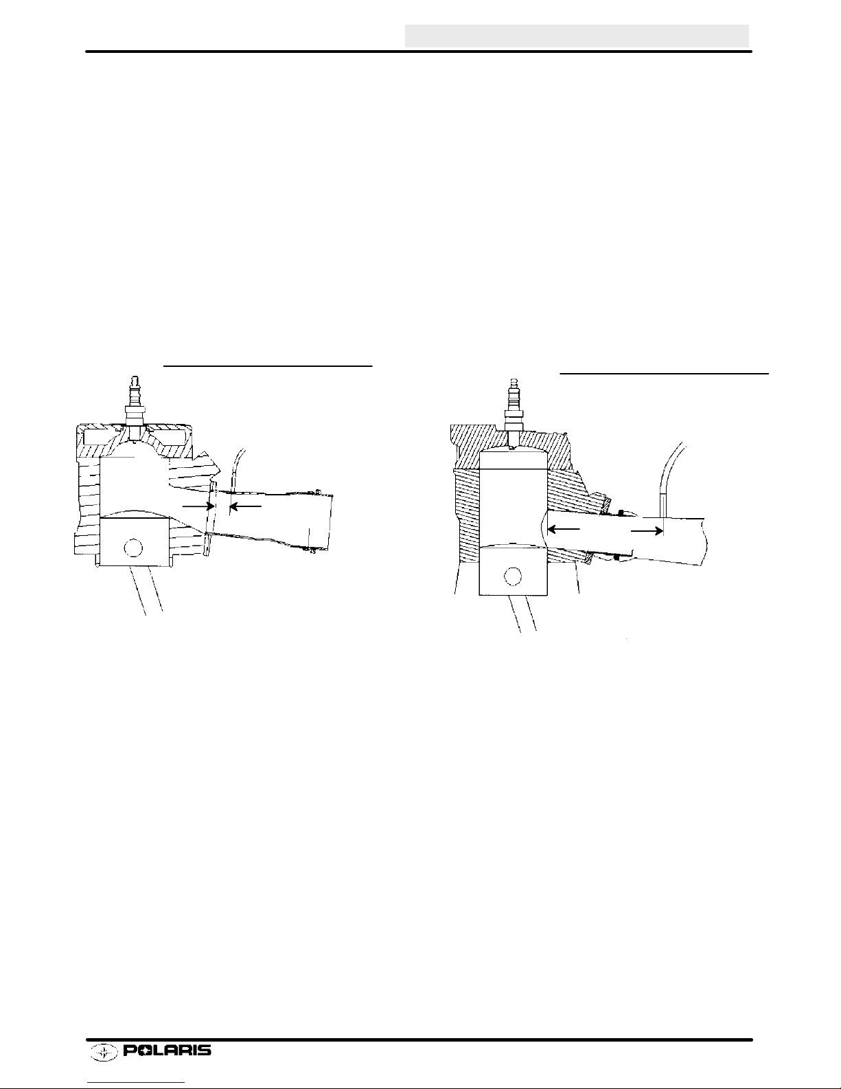
Exhaust Gas Temperature
Exhaust Gas Temperature
ENGINE
Above 1200_F
649_C
1150 - 1200_F
621 - 649_C
Multiple Cylinder Single Pipe
NOTE: The temperatures given are approximate and should only be used as an example. You must determine the
EGT numbers that are correct for your machine
--DETONATION
--NORMAL
1.5”
38mm
Above 1200_F
649_C
1150 - 1200_F
621 - 649_C
5.0”
127mm
1PipePerCylinder
--DETONATION
--NORMAL
For more information contact Bill Rader (715) 355-5157
2.53
Page 86

ENGINE
Piston Wash and Spark Plug color
Changing temperature, barometer, altitude, and fuel supply are just a few of the factors that can affect the day to
day performance of your engine. That is why using Exhaust Gas Temperatures (EGTs) are important for maintaining optimum performance.
There are two methods for helping you determine what the EGTs are for your machine. Piston wash and the coloring of your spark plug.
The piston wash is by far the most valuable tool in concluding EGTs, with the spark plug color running a distant
second. Use the illustrations below to help you establish the EGTs for your machine.
Piston Wash
n Wet and Black wash indicates too rich a
fuel mixture
Wash
Correct
n If the wash is 1/4” - 3/8” and cocoa
brown, the machine’s EGTs are just right.
Dry
n A dry, ash colored piston indicates too lean
a mixture for the operating conditions.
Spark Plug Color
n If the plug is wet or very dark, the fuel is
running too rich.
Correct
n If the plug is light to cocoa brown, the
machine’s EGTs are just right.
n A ash white plug with speckles indicates
too lean a mixture for the operating conditions.
Once the proper jetting is established, you can reference the EGT gauge for your baseline numbers. Then, if there is
a rise or fall of 25 degrees, you must jet accordingly to return your EGTs to the baseline numbers.
2.54
Page 87

Cylinder Head Inspection
1. Inspect each cylinder head for warping. Replace
cylinder head if warp exceeds service limit.
Cylinder Head Warp
Service Limit: .003s (.08mm)
Cylinder Measurement
2. Inspect each cylinder for wear, scratches, or
damage. If no damage is evident, measure the
cylinder for taper and out of round with a
telescoping gauge or a dial bore gauge. Measure
the bore 1/2s from the top of the cylinder; in line with
the piston pin and 90q to the pin to determine if the
bore is out of round. Repeat the measurements at
the middle and bottom of the cylinder to determine
taper or out of round at the bottom. Record all
measurements.
To p
ENGINE
Y
X
Cylinder Taper
Limit: .002 Max.
Cylinder Out of Round
Limit: .002 Max.
Middle
Bottom
Y
X
Y
X
2.55
Page 88

ENGINE
Piston Inspection/Measurement
1. Check piston for scoring or cracks in piston crown or
pin area. Excessive carbon buildup below the ring
lands is an indication of piston, ring or cylinder wear.
2. Measure piston outside diameter at a point 10 mm
(3/8s) up from the bottom of the skirt at a 90q angle
to the direction of the piston pin (domestic engines).
For Fuji engines, measure 1/2s (12.7mm) up from
the bottom of the piston skirt. Record the
measurement for each piston.
NOTE: The piston must be measured at this point to
provide accurate piston-to-cylinder clearance measurement.
3. Subtract this measurement from the minimum
cylinder measurement recorded previously. If
clearance exceeds the service limit, the cylinder
should be re-bored and new pistons and rings
installed.
Piston Ring Installed Gap
90q to pin
FUJI ENGINES - Measure 1/2s
(12.7mm) up from bottom of skirt
DOMESTIC ENGINES - Measure
3/8s (10.0mm) up from bottom of skirt
1. Position ring 1/2I (1.3 cm.) from the top of the
cylinder using the piston to push it squarely into
place. Measure installed gap with a feeler gauge at
both the top and bottom of the cylinder.
NOTE: A difference in end gap indicates cylinder taper.
The cylinder should be measured for excessive taper
and out of round. Replace rings if the installed end gap
exceeds the service limit.
NOTE: Always check piston ring installed gap after reboring a cylinder or when installing new rings.
Cylinder
Cylinder
1/2s (1.3cm.)
Piston Ring
Feeler Gauge
1/2s (1.3cm.)
Piston Ring
Up
2.56
Straight Edge
Piston Ring Cutaway
Keystone Piston Ring
Page 89

ENGINE
Oil Pump Operation and Troubleshooting
Any time the engine is disassembled or repaired, it is important that the oil supply from the pump to the engine
be checked.
NOTE: Banjo type or pressed in valves should open with 2 to 7 lbs. of pressure. Perform this test with 40:1 premix
in fuel tank.
1. With engine in chassis, oil reservoir full, and pump
bled, remove two oil feed line banjo bolts (A) from
their location on the manifold or carburetors. NOTE:
Install new sealing washers upon installation on
either side of the banjo check valve.
2. Loosely thread only the banjo bolts back into the
manifold or carburetors.
3. Place oil feed lines with their check valves away
from the clutch area. Start the engine and let it idle
at normal idle RPM.
4. Lift oil pump control lever up to its maximum flow
position.
5. Drops of oil should be visible from the banjo check
valves after the engine is idled one to two minutes,
with a drop occurring approximately every few
seconds.
Pressed
Apply Pressure Here
To Te st
Banjo
6. If oil does not flow from one of the check valves,
remove oil line from check valve and again idle
engine. If oil then flows, the check valve is defective
and must be replaced.
7. If oil does not flow with check valves removed from
their feed lines, the malfunction is one of the
following:
S Inline filter blocked
S Air not bled from oil pump
S Feed lines leaking
S Oil tank vent restricted or kinked
S Defective pump.
2.57
Page 90

ENGINE
Oil Pump Bleeding
The oil pump must always be bled following any service to the injector system or engine which allows the loss
of oil and subsequent entrapped air during reassembly.
1. Fill oil reservoir with Polaris injector oil.
2. Loosen brass hex head screw (A). After a short time
oil should flow from beneath the screw head to
indicate the pump is free of air.
3. Tighten bleed bleed screw.
Oil Pump Adjustment - All Models
After the engine RPM and carburetor adjustments have
been made, the oil pump must also be adjusted.
1. With engine shut off and throttle in its idle position,
the pump lever index mark (A) must align with the
pump housing boss index mark (B).
A
2. Loosen lock nuts on cable housing sleeve and vary
cable housing length as required. NOTE: Verify
that pump lever is actuated upon initial throttle
opening.
Oil Pump Drive Gear End Play Adjustment
If the oil pump, crankcase, or any other oil pump drive
component is replaced, inspect the drive gear end play
using the following procedure:
1. Measure distance from oil pump mounting surfaceto
bushing. Call this measurement “A”.
NOTE: Make sure the bushing is fully seated in the
crankcase.
B
A
2.58
Page 91

ENGINE
Oil Pump Drive Gear End Play Adjustment - Fuji
2. Measure distance from oil pump mounting flange
surface to end of seal flange as shown. Call this
measurement “B”.
3. Subtract measurement “B” from “A” to determine
total bushing end play.
4. Measure thickness of existing shims and subtract
from total bushing end play determined in step 3.
5. Add or subtract shims as required to provide
specified end play.
6. Lightly grease a new O-ring and install it on the
pump. Install pump, engaging slot in shaft with drive
gear. Apply Loctite¥ 242 to bolts and torque evenly
to 78 in. lbs. (9 Nm).
Measurement A
Oil Pump Mounting Bolt Torque
(242 Blue)
78 in. lbs (9 Nm)
Optional Shims:
PN 3083671 = .006s(.15mm)
PN 3083672 = .012s (.3mm)
PN 3083673 = .024s (.6mm)
End Play
.008 - .016s (.203 - .406 mm)
Measurement B
2.59
Page 92
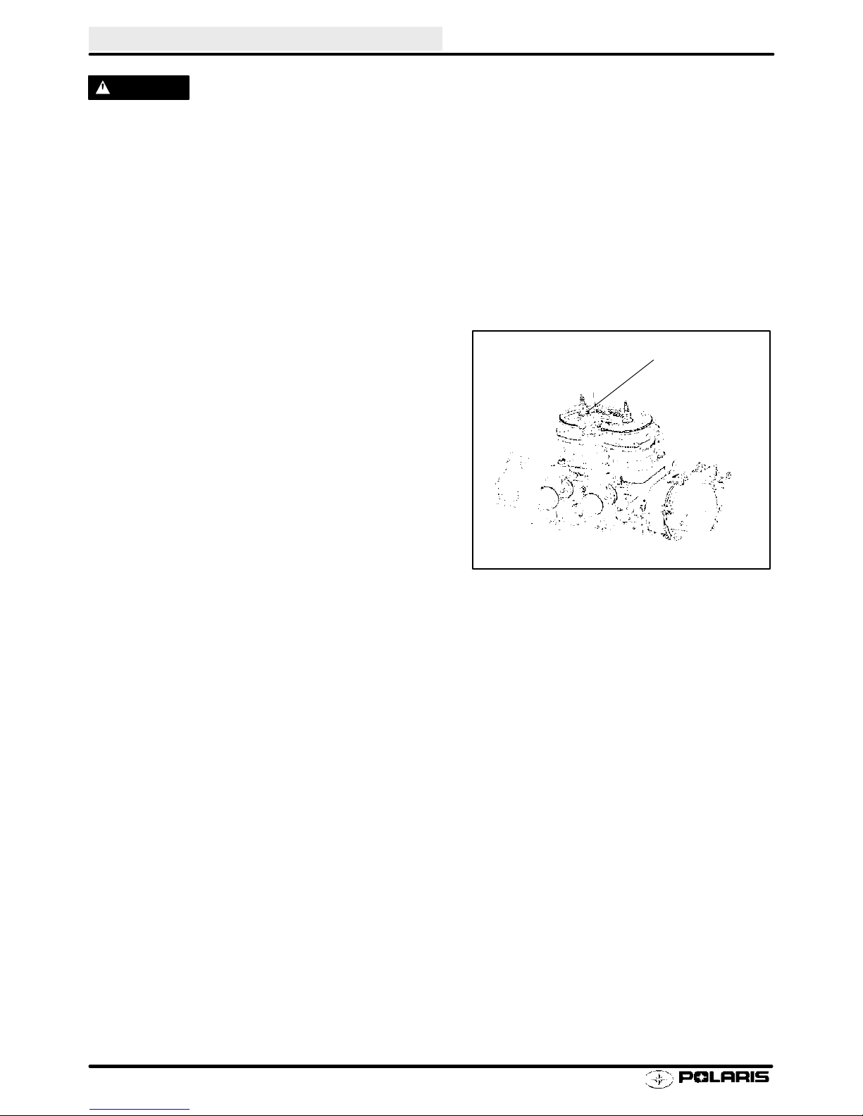
ENGINE
WARNING
Never remove the pressure cap when the engine is warm or hot. If the pressure cap is to be removed, the engine
must be cool. Severe personal injury could result from steam or hot liquid. Use of a non-standard pressure cap
will not allow the recovery system to function properly. If the cap should need replacement, install the correct
Polaris cap with the same pressure rating. Refer to the appropriate parts manual.
NOTE: Always use Polaris premium antifreeze 60/40 premix. Bleed system at specified RPM or air will remain
trapped in system, which may result in overheating.
Filling and Bleeding Procedure
If the cooling system should become low in the reservoir
tank and/or filler neck, the system should be bled of any
trapped air using one of the following procedures, depending on model.
440/500/600/700 Domestic Twins Bleeding Procedure
1. Fill cooling system . Leave pressure cap off.
2. With engine running at specified idle speed, loosen
bleed screw on thermostat housing.
3. Continue adding antifreeze mixture to reservoir until
system is purged of air.
4. Close bleed screw and tighten securely.
5. Fill reservoir bottle until coolant level is between the
minimum and maximum fill marks.
6. Replace pressure cap.
7. Start engine and test for leaks.
500/600/700 Libertyt Twins
Bleed Screw
2.60
Page 93

Cooling System - 440 Pro X
ENGINE
NOTE: When leak testing cooling system, system
pressure should not exceed 2 lbs. less than cap pressure.
ENGINE
CENTER
COOLER
440 Pro X
COOLANT BOTTLE
TUNNEL STRIP COOLERS
2.61
Page 94

ENGINE
Cooling System 600 Pro X
ENGINE
CENTER
COOLER
600 Pro X
COOLANT BOTTLE
TUNNEL STRIP COOLERS
2.62
Page 95

Cooling System 700 / 800 Pro X
ENGINE
ENGINE
CENTER
COOLER
700/800 PRO X
COOLANT BOTTLE
TUNNEL STRIP COOLERS
2.63
Page 96

ENGINE
Troubleshooting
PROBLEM PROBABLE CAUSE
Will not start/
hard starting
Low compression
No spark -Spark plug fouled
Engine idles but
no acceleration
Engine runs but
fails to reach
maximum RPM
Engine runs but
fails to idle
Engine runs,
but overloads
with fuel
Carburetion and
plug fouling
Engine runs but
overheats
-Check ignition switch for run position, moisture contamination
-Check auxiliary shut-off switch operation
-Check fuel supply
-Check wiring from engine to coil(s) or spark plug(s)
-Check spark plug(s)
-Disconnect engine connector to eliminate any shorts that might be in the system
-If starter won’t work (electric models), check wires from starter solenoid and battery or check battery
and battery cables
-Open or broken reed valves
-Crankcase plug is out
-Head gasket faulty
-Poor ring sealing, piston damage
-Secondary coil bad or wires disconnected
-Primary coil shorted or open
-Ignition switch shorted, contaminated with moisture
-Auxiliary switch shorted or contaminated with moisture
-Restricted fuel flow/air flow
-Clogged main jet
-Timing
-Clutching
-Clogged fuel filter
-Incorrect track tension
-Incorrect main jet
-Throttle slides not fully open
-Chain too tight
-Clutching
-Excessive driveline friction (Hi-Fax overheating)
-Incorrect air mixture setting
-Throttle stop screw incorrectly adjusted
-Dirt in pilot jet
-Low compression
-Tight belt
-Piston damage
-Chokes not seating
-Chokes are not seating
-Fuel pump diaphragm is ruptured (caused by engine backfiring)
-Carburetor slides are not synchronized
-Too large main jet
-Needle and seat not seating properly
-Incorrect float level
-Check reed valve condition
-If a lot of riding is on trails, and plugs foul and get black when doing so, verify
carb sync, oil pump adjustment, pilot screw setting, spark plug type and gap, venting for carbs, proper
jetting for altitude and temperature, belt tension, clutch operation. If tune up items are correct, check:
float level, jet needle position, jet needle wear, inlet needle and seat wear, etc.
-Coolant level
-Incorrect main jet
-Incorrect timing
-Incorrect spark plug
-Water pump belt loose or broken
-Cooling restriction
-Air in cooling system
-Inadequate snow for cooling (ice and/or marginal conditions)
all
tune up adjustments:
2.64
Page 97
Jet Part Numbers 3.1 -- 3.3..............................
Jet Needle Overview 3.4...........................
Mikuni TMX--34 Exploded View 3.5..................
Mikuni TM 38/40 Exploded View 3.6.................
Mikuni VM 34 SS Exploded View 3.7.................
Fuel Delivery System 3.8...........................
Carbueretion Operation 3.9 -- 3.14.........................
Component Effect vs. Throttle Opening 3.15...........
VM 34 SS Throttle Syncronization Proceedure 3.16.....
Mikuni TM 38/40 Service 3.17 -- 3.21........................
Mikuni TM 38/40 Throttle Syncronization 3.22 -- 3.23..........
Mikuni TMX Service 3.24 -- 3.26............................
Adjustments 3.27 -- 3.28...................................
Choke 3.29........................................
Fuel Pump 3.30....................................
Troubleshooting 3.31 -- 3.32................................
Page 98

Page 99

CARBURETION
Jet Part Numbers
Whenever servicing the carburetor or fuel system, it is important to heed the following warnings.
WARNING
Gasoline is extremely flammable and explosive under certain conditions.
Always stop the engine and refuel outdoors or in a well ventilated area.
Do not smoke or allow open flames or sparks in or near the area where refueling is performed or where
gasoline is stored or used.
Do not overfill the tank. Do not fill the tank neck.
If you get gasoline in your eyes or if you swallow gasoline, see your doctor immediately.
If you spill gasoline on your skin or clothing, immediately wash it off with soap and water and change clothing.
Never start the engine or let it run in an enclosed area. Gasoline powered engine exhaust fumes are poisonous and can cause loss of consciousness and death in a short time.
Jet Part Numbers
The following chart lists main and pilot jets and the part number of each that are presently available.
Mikuni Mikuni
PILOT JET NO. PART NO. PILOT JET NO. PART NO.
25 3130064 60 3130071............ ........
30 3130065............
35 3130066............
40 3130067............
45 3130068............
50 3130629............
55 3130070............
Mikuni Mikuni
HEX HEAD HEX HEAD
MAIN JET NO. PA RT NO . MAIN JET NO. PART N O.
80 3130099 250 3130128 510N 3131400............ ............ ........
85 3130100 260 3130129 520N 3131401............ ............ ........
90 3130101 270 3130130 530N 3131402............ ............ ........
95 3130102 280 3130131 540N 3131408............ ............ ........
100 3130103 290 3130132 550N 3131409........... ............ ........
105 3130104 300 3130133 560N 3131410........... ............ ........
110 3130105 310 3130134........... ............
115 3130106 320 3130135 The “N” series jets have the same........... ............
120 3130107 330 3130136 flow characteristics as the following............ ............
125 3130108 340 3130137 510N = 540........... ............
130 3130109 350 3130138 520N = 580........... ............
135 3130110 360 3130139 530N = 600........... ............
140 3130111 370 3130290 540N = 620........... ............
145 3130112 380 3130140 550N = 660........... ............
150 3130113 390 3130480 560N = 700........... ............
155 3130114 400 3130141........... ............
160 3130115 410 3130599 Do NOT substitute a........... ............
165 3130116 420 3130142 530 Main Jet in place of a 530N ............ ............
170 3130117 430 3130143........... ............
175 3130118 440 3130144........... ............
180 3130119 450 3130145........... ............
185 3130120 460 3130146........... ............
190 3130121 470 3130147........... ............
195 3130122 490 3130148........... ............
200 3130123 500 3130149........... ............
210 3130124...........
220 3130125...........
230 3130126...........
240 3130127...........
3.1
Page 100

CARBURETION
Mikuni TM-38/TM-40 Jet Part Numbers
DESCRIPTION PART NUMBER DESCRIPTION PART NUMBER
Jet Needles Pilot Air Jets Cont.
Jet Needle J8-9FH04-57 3130794 Pilot Air Jet 1.0 3131257
Jet Needle J8-9EH01-57 3130795 Pilot Air Jet 1.1 3131258
Jet Needle J8-9DH01-54 3130796 Pilot Air Jet 1.2 3131259
Jet Needle J8-9CJB01-50 3130797 Pilot Air Jet 1.3 3131260
Jet Needle J8--8BEY01 3131250 Pilot Air Jet 1.4 3131261
Jet Needle J8--9DFH06--57 3131253 Pilot Air Jet 1.5 3131262
Jet Needle J8--9DFH07--60 3131268 Pilot Air Jet 1.6 3131263
Jet Needle J8--9DFH10--57 3131313 Pilot Air Jet 1.7 3131264
Jet Needle J8-- 9DGI01--60 3131377 Pilot Air Jet 1.8 3131265
Jet Needle J8--9DGJ02--57 3131378 Pilot Air Jet 1.9 3131266
Jet Needle J8-- EFH01--60 3131207 Pilot Air Jet 2.0 3131267
Jet Needle J8-- 9EFY02--61 3131202 Throttle Valves
Pilot Air Jets (Short) Piston Valve 1.5 3130940
Pilot Air Jet 0.5 3130773 Piston Valve 2.0 3130789
Pilot Air Jet 0.6 3130774 Piston Valve 2.5 3130790
Pilot Air Jet 0.7 3130775 Piston Valve 3.0 3130791
Pilot Air Jet 0.8 3130776 Piston Valve 3.5 3130792
Pilot Air Jet 0.9 3130777 Piston Valve 4.0 3130793
Pilot Air Jet 1.0 3130778
Pilot Air Jet 1.1 3130779
Pilot Air Jet 1.2 3130780
Pilot Air Jet 1.3 3130781
Pilot Air Jet 1.4 3130782
Pilot Air Jet 1.5 3130783
Pilot Air Jet 1.6 3130784
Pilot Air Jet 1.7 3130785
Pilot Air Jet 1.8 3130786
Pilot Air Jet 1.9 3130787 Starter Jets Part Number
Pilot Air Jet 2.0 3130788 Starter Jet 130 3130805
Pilot Air Jets (Long) Starter Jet 135 3130767
Pilot Air Jet 0.5 3131255 Starter Jet 140 3130768
Pilot Air Jet 0.6 3131249 Starter Jet 145 3130769
Pilot Air Jet 0.7 3131256 Starter Jet 150 3130770
Pilot Air Jet 0.8 3131254 Starter Jet 155 3130771
Pilot Air Jet 0.9 3131203 Starter Jet 160 3130772
The part numbers for main jets and pilot jets are the same as Mikuni VM round slide carburetors.
3.2
 Loading...