

Page 1

2007 SPORTSMAN 700/800/800 X2 EFI
SERVICE MANUAL
FOREWORD
This service manual is designed prim arily for use by ce rtified Polaris Mas ter Service Dealer technicians in a properly
equipped shop and should be kept available for reference. All references to left and right side of the vehicle are from
the operator's perspective when seated in a normal riding position.
Some procedures outlined in this manual require a sound knowledge of mechanical theory, tool use, and shop
procedures in order to perform the work safely and correctly . T echnicians should read the text and be familiar with service
procedures before starting the work. Certa in procedur es require the use o f special tools. Use o nly the proper to ols as
specified.
Comments or suggestions about this manual may be d irected to: Service Publications Dept. @ Polaris Sales Inc. 2100
Hwy 55 Medina Minnesota 55340.
2007 Sportsman 700/800/ 800 X2 EFI Service Manual PN 9920378
© Copyright 2006 Polaris Sales Inc. All information contained within this publication is based on the latest product information at the time of publication . Due to constant
improvements in the design and quality of production component s, some minor discrep ancies may result between t he actual vehicle and the inf ormation presented in t his
publication. Depictions and/or procedures in this publ ication are intended f or reference use only. No liability can be accepted for omission s or inaccuracies. Any r eprinting
or reuse of the depictions and/or procedures contained within, whether whole or in part, is expressly prohibited. Printed in U.S.A.
Page 2
UNDERSTANDING MANUAL SAFETY LABELS AND DIRECTIONS
Throughout this manual, important information is brought to your attention by the following symbols:
WARNING
SAFETY ALERT WARNING indicates a potential hazard that may result in severe injury or death to the operator, bystander or
person(s) inspecting or servicing the vehicle.
CAUTION
SAFETY ALERT CAUTION indicates a potential hazard that may result in minor personal injury or damage to the vehicle.
CAUTION
CAUTION indicates special precautions that must be taken to avoid vehicle damage or property damage.
NOTE:
NOTE provides key information by clarifying instructions.
IMPORTANT:
IMPORTANT provides key reminders during disassembly, assembly and inspection of components.
TRADEMARKS
POLARIS ACKNOWLEDGES THE FOLLOWING PRODUCTS MENTIONED IN THIS MANUAL:
Loctite, Registered Trademark of the Loctite Corporation
Nyogel, Trademark of Wm. F. Nye Co.
Fluke, Registered Trademark of John Fluke Mfg. Co.
Mity-Vac, Registered Trademark of Neward Enterprises, Inc.
Torx, Registered Trademark of Textron
Hilliard, Trademark of the Hilliard Corporation
Warn, Trademark of Warn Industries
Some Polaris factory publications can be downloaded from www.polarisindustires.com, purchased from www.purepolaris.com or
by contacting the nearest Polaris dealer.
Page 3

GENERAL
1
MAINTENENCE
ENGINE
FUEL SYSTEM
BODY / SUSPENSION
CLUTCH
2
3
4
5
6
TRANSMISSION
FINAL DRIVE
BRAKES
ELECTRICAL
INTERNATIONAL
7
8
9
10
11
Page 4

NOTES
Page 5

GENERAL INFORMATION
CHAPTER 1
GENERAL INFORMATION
MODEL INFORMATION . . . . . . . . . . . . . . . . . . . . . . . . . . . . . . . . . . . . . . . . . . . . . . . . . . 1.2
MODEL NUMBER. . . . . . . . . . . . . . . . . . . . . . . . . . . . . . . . . . . . . . . . . . . . . . . . . . . . . . .1.2
ENGINE DESIGNATION NUMBERS. . . . . . . . . . . . . . . . . . . . . . . . . . . . . . . . . . . . . . . .1.2
VIN IDENTIFICATION . . . . . . . . . . . . . . . . . . . . . . . . . . . . . . . . . . . . . . . . . . . . . . . . . . .1.2
TRANSMISSION I.D. LOCATION. . . . . . . . . . . . . . . . . . . . . . . . . . . . . . . . . . . . . . . . . . .1.2
ENGINE AND MACHINE SERIAL NUMBERS. . . . . . . . . . . . . . . . . . . . . . . . . . . . . . . . .1.2
SPORTSMAN ‘DELUXE’ AND ‘STANDARD’ MODEL COMPONENT COMPARISON . .1.3
2007 SPORTSMAN 700 EFI . . . . . . . . . . . . . . . . . . . . . . . . . . . . . . . . . . . . . . . . . . . . . . . 1.4
MODEL NUMBER: A07MH68AX, A07MH68AY, A07MH68AZ, . . . . . . . . . . . . . . . . . . .1.4
2007 SPORTSMAN 800 EFI . . . . . . . . . . . . . . . . . . . . . . . . . . . . . . . . . . . . . . . . . . . . . . . 1.6
MODEL NUMBER: A07MH76A, A07MN76A, A07MH76F. . . . . . . . . . . . . . . . . . . . . . . .1.6
2007 SPORTSMAN X2 800 EFI . . . . . . . . . . . . . . . . . . . . . . . . . . . . . . . . . . . . . . . . . . . . 1.8
MODEL NUMBER: A07TH76A, A07TN76A . . . . . . . . . . . . . . . . . . . . . . . . . . . . . . . . . .1.8
MISC. NUMBERS/CHARTS . . . . . . . . . . . . . . . . . . . . . . . . . . . . . . . . . . . . . . . . . . . . . . 1.10
PUBLICATIONS . . . . . . . . . . . . . . . . . . . . . . . . . . . . . . . . . . . . . . . . . . . . . . . . . . . . . . .1.10
PAINT CODES . . . . . . . . . . . . . . . . . . . . . . . . . . . . . . . . . . . . . . . . . . . . . . . . . . . . . . . .1.10
REPLACEMENT KEYS . . . . . . . . . . . . . . . . . . . . . . . . . . . . . . . . . . . . . . . . . . . . . . . . .1.10
STANDARD TORQUE SPECIFICATIONS. . . . . . . . . . . . . . . . . . . . . . . . . . . . . . . . . . .1.11
SPECIAL TOOLS . . . . . . . . . . . . . . . . . . . . . . . . . . . . . . . . . . . . . . . . . . . . . . . . . . . . . .1.11
SAE TAP DRILL SIZES . . . . . . . . . . . . . . . . . . . . . . . . . . . . . . . . . . . . . . . . . . . . . . . . .1.12
METRIC TAP DRILL SIZES . . . . . . . . . . . . . . . . . . . . . . . . . . . . . . . . . . . . . . . . . . . . . .1.12
DECIMAL EQUIVALENTS . . . . . . . . . . . . . . . . . . . . . . . . . . . . . . . . . . . . . . . . . . . . . . .1.12
CONVERSION TABLE. . . . . . . . . . . . . . . . . . . . . . . . . . . . . . . . . . . . . . . . . . . . . . . . . .1.13
GLOSSARY OF TERMS. . . . . . . . . . . . . . . . . . . . . . . . . . . . . . . . . . . . . . . . . . . . . . . . .1.14
1
1.1
Page 6
GENERAL INFORMATION
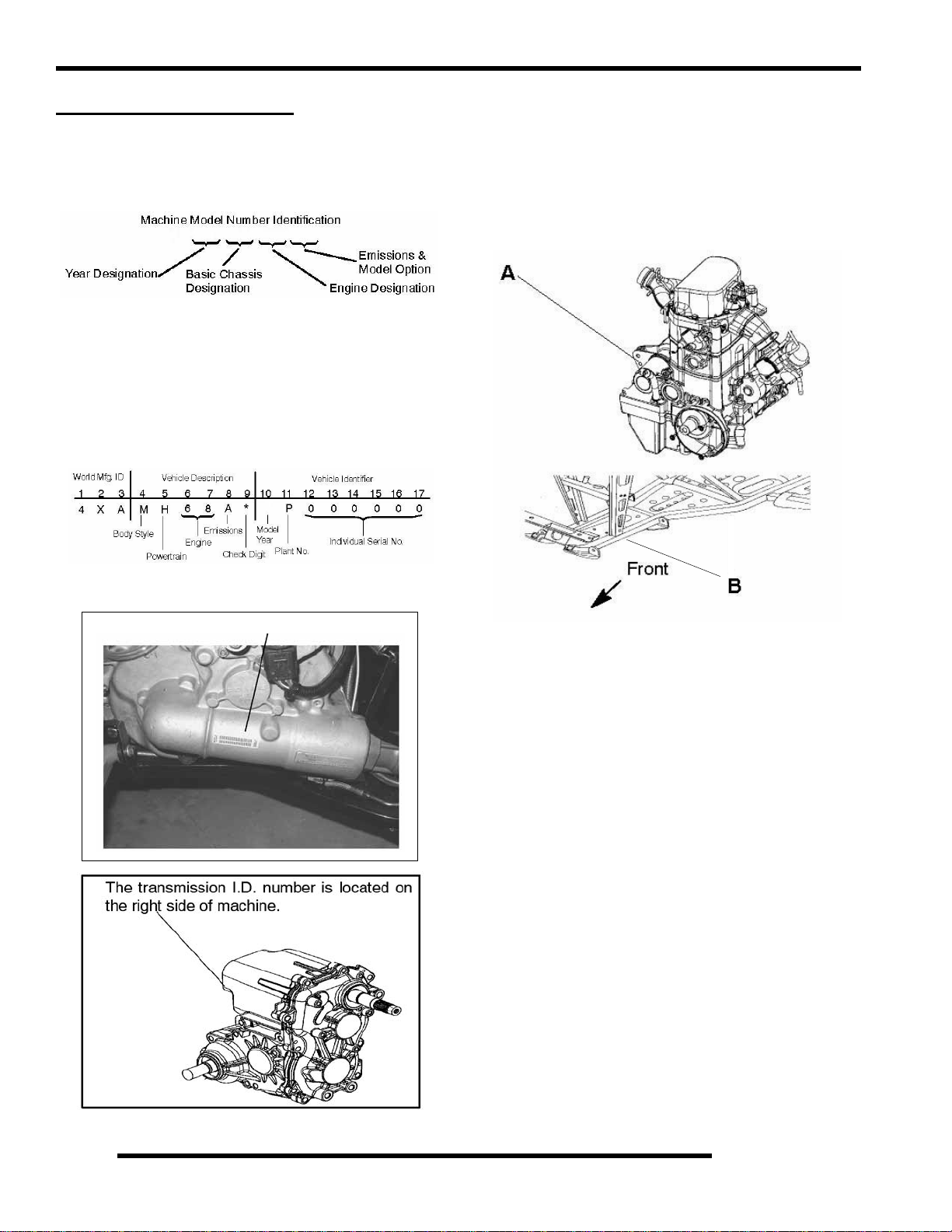
MODEL INFORMATION
Model Number
The machine model number must be used with any
correspondence regarding warranty or service.
A07 MH76 AU
Engine Designation Numbers
EH068OLE - T win Cylinder, Liquid Cooled,4 Stroke, Electric
Start
EH076OLE - Twin Cylinder, Liquid Cooled,4 Stroke, Electric
Start
VIN Identification
7
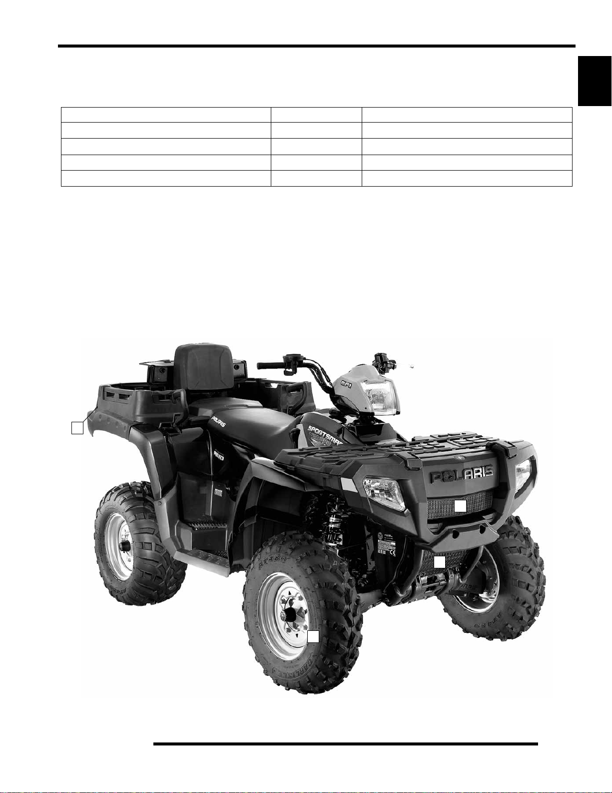
Engine and Machine Serial Numbers
Be sure to refer to the engine model number and serial number
whenever corresponding about an engine.
This information can be found on the sticker applied to the top
side of the crankcase (A). An additional number is stamped on
the side of the crankcase beneath the cylinder coolant elbow.
x
x
x
x
x
x
x
x
TRANSMISSION I.D. LOCATION
Sportsman X2
Sportsman
The machine model number and serial number are important for
vehicle identification. The machine serial number is stamped on
the lower left side of the frame tube (B).
1.2
Page 7
PUBLICATIONS
GENERAL INFORMATION
Table 1-1: Publications
Year Model Model No.
2007 Sportsman 700 EFI
2007 Sportsman 800 EFI
2007 Sportsman X2 800 EFI
2007
Sportsman 800 EFI
International
A07MH68A
A07MN68A
A07MH76A
A07MN76A
A07TH76A
A07TN76A
A07MH76F 9920374 9920379
Owner's
Manual PN
9920374 9920375
9920374 9920379
9920632 9920903
Manual PN
PAINT CODES
Table 1-2: Paint Codes
PAINTED PART
Sportsman 700/800 EFI Frame Black 9440 P-067
COLOR
DESCRIPTION
DITZLER
NUMBER
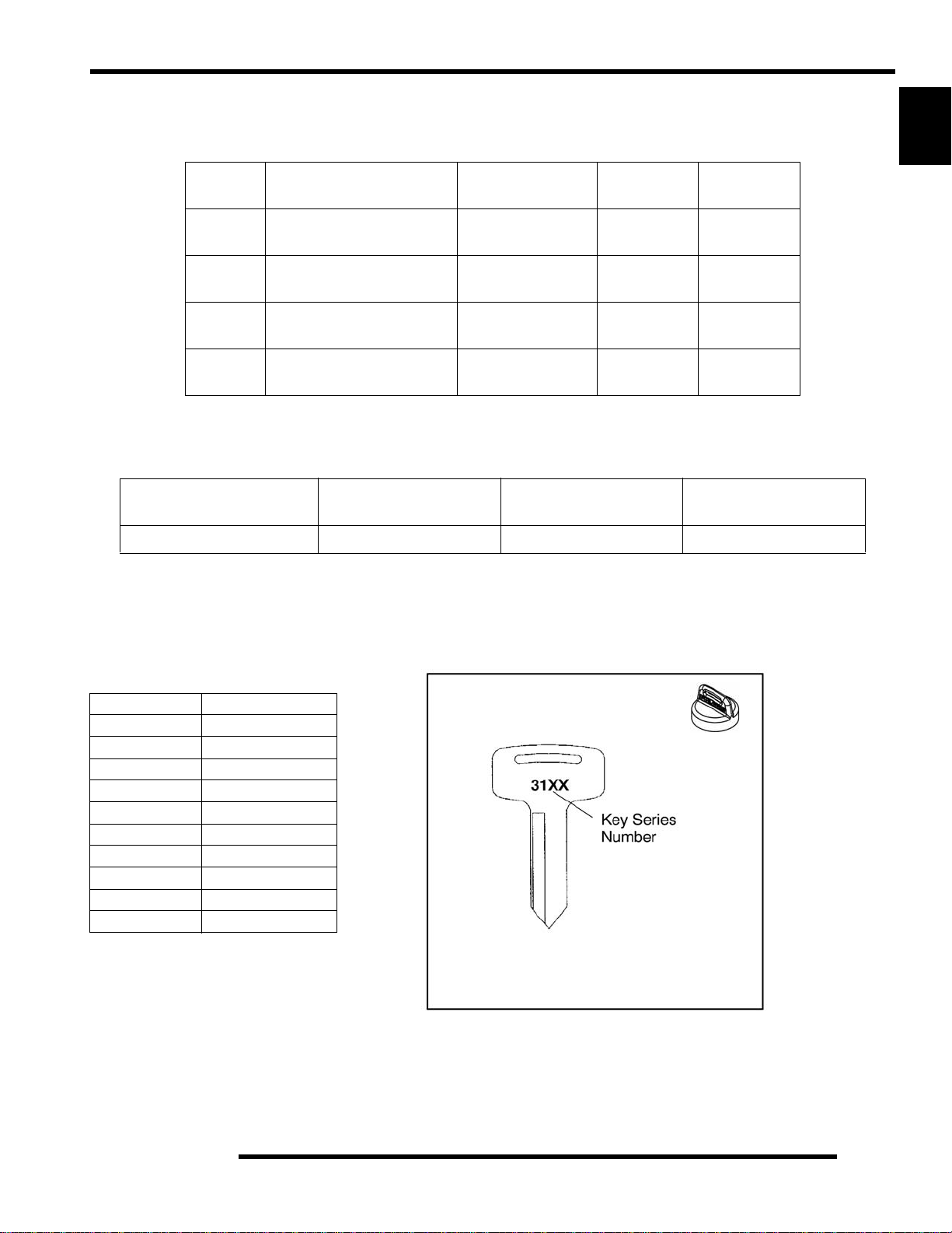
REPLACEMENT KEYS
1
Parts
POLARIS
NUMBER
Replacement keys can be made from the original key. To identify which series t he key is, ta ke the first tw o digits on the original
key and refer to the chart to the right for the proper part number. Should both keys become lost, ignition switch replacement is
required.
Table 1-3: Key Numbers
Series # Part Number
20 4010278
21 4010278
22 4010321
23 4010321
27 4010321
28 4010321
31 4110141
32 4110148
67 4010278
68 4010278
Key Boot
PN 5433534
1.3
Page 8
GENERAL INFORMATION
Sportsman ‘Deluxe’ and ‘Standard’ Model Component Comparison
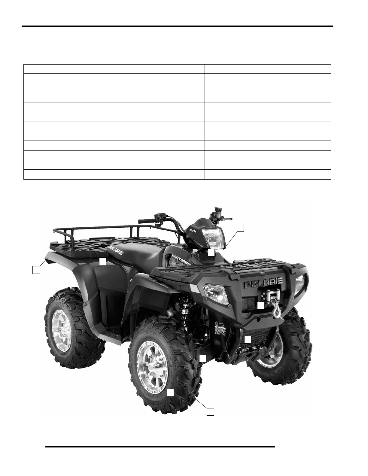
For Model Year 2007, a Sportsman ‘Deluxe’ and ‘Standard’ model were offered. Use the following table as a guide:
SPORTSMAN ‘DELUXE’ MODEL Item Location SPORTSMAN ‘ST ANDARD’ MODEL
Winch 1 No Winch
PXT Tires 2 Titan Tires
PVT w/EBS 3 Non-EBS (800 X2 excluded)
Rear Work Lights 4 No Work Lights
Front Drive w/ Active Descent Control (ADC) 5 No Active Descent Control (ADC)
Speed Sensor Wiring for ADC 6 No Sensor Wiring Change
Rear Rack Extension 7 No Rack Extension
Cast Aluminum Wheels 8 Steel Wheels
Dual Exhaust (800 EFI only) 9 Single Exhaust (800 EFI and X2)
Wire Harness w/ Active Descent Control (ADC) 10 Standard Wire Harness
ECU w/ Active Descent Control (ADC) 10 Standard ECU
3
7
10
9
4
1
5
6
Deluxe Model Pictured
8
1.4
2
Page 9
GENERAL INFORMATION
Sportsman X2 ‘Deluxe’ and ‘Standard’ Model Component Comparison
For Model Year 2007, an X2 ‘Deluxe’ and ‘Standard’ model were offered. Use the following table as a guide:
X2 ‘DELUXE’ MODEL Item Location X2 ‘STANDARD’ MODEL
Winch 1 No Winch
Rear Work Lights 2 No Work Lights
Front Drive w/ Active Descent Control (ADC) 3 No Active Descent Control (ADC)
Cast Aluminum Wheels 4 Steel Wheels
1
2
1
3
Standard Model Pictured
4
1.5
Page 10
GENERAL INFORMATION
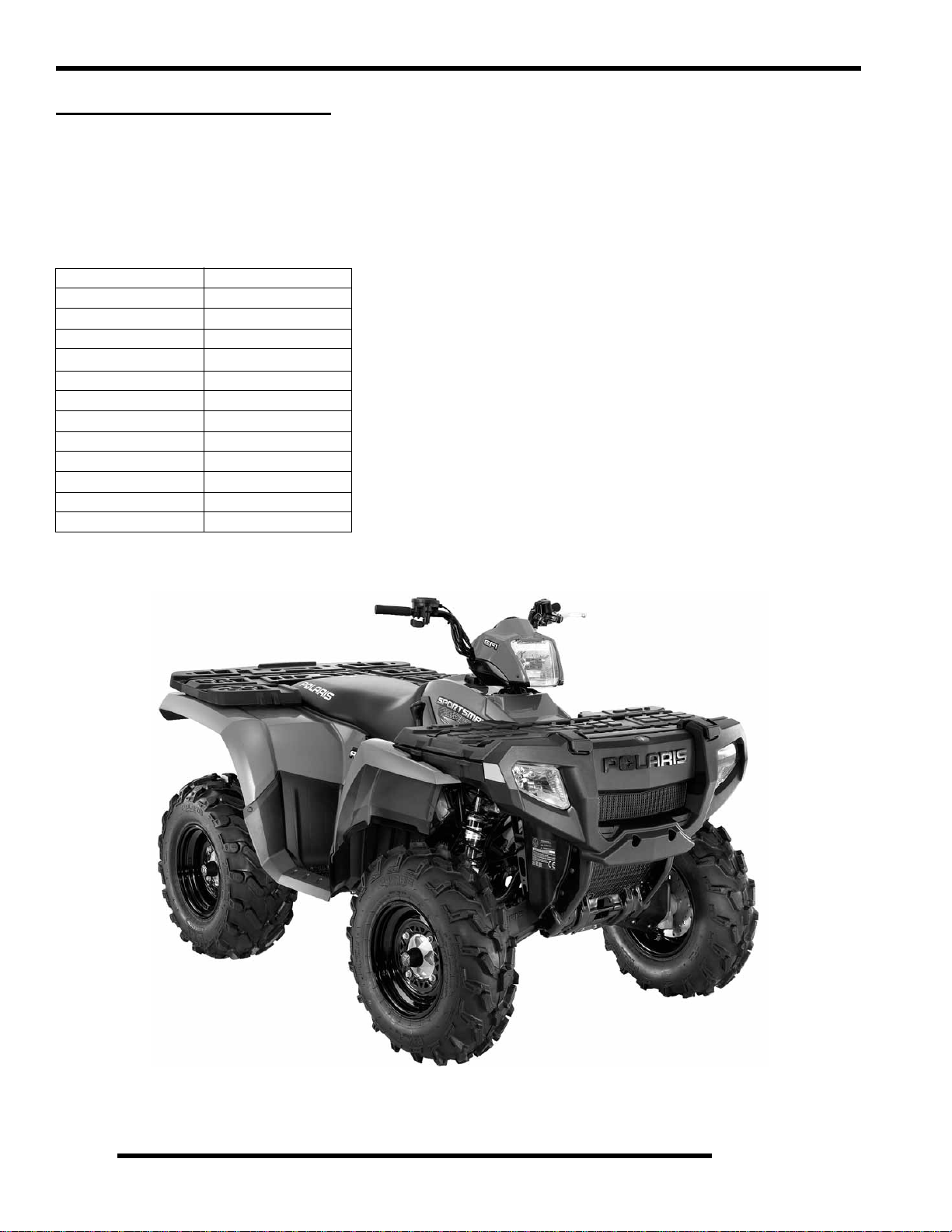
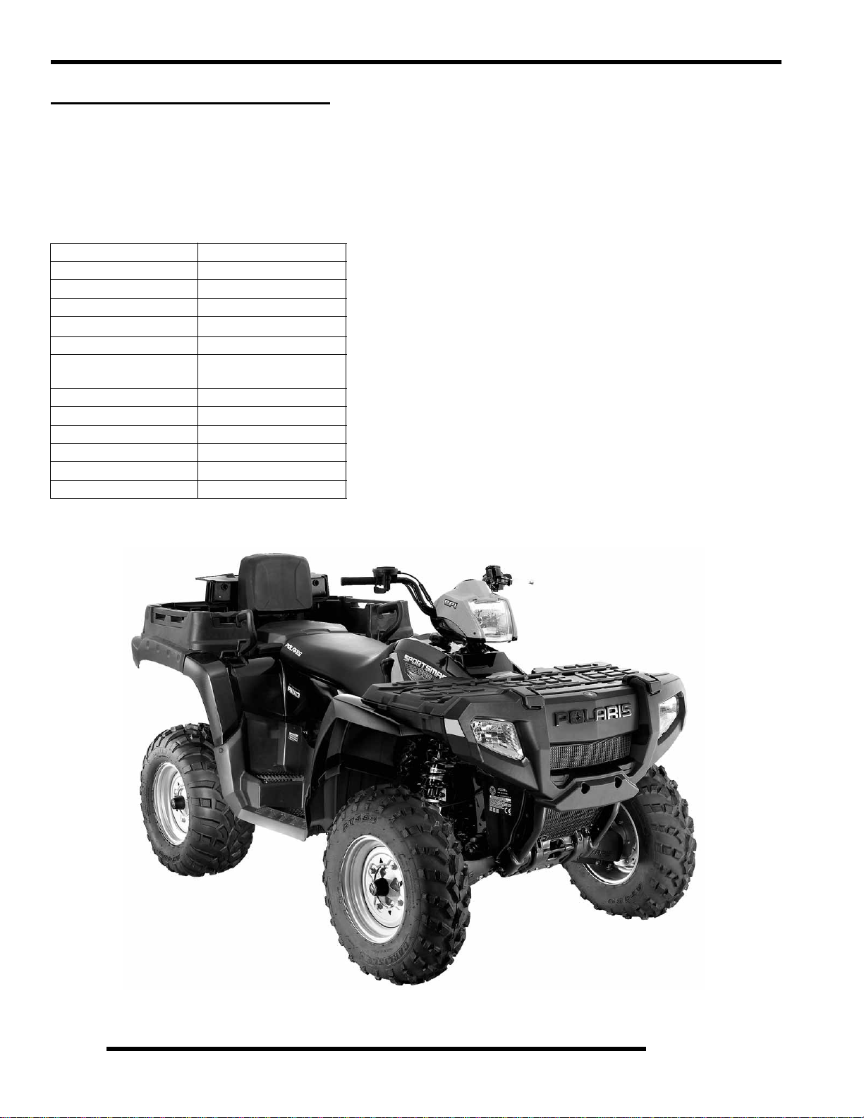
2007 SPORTSMAN 700 EFI
MODEL NUMBER: A07MH68AX, AY, AZ
(Standard Model Only)
ENGINE MODEL: EH068OLE
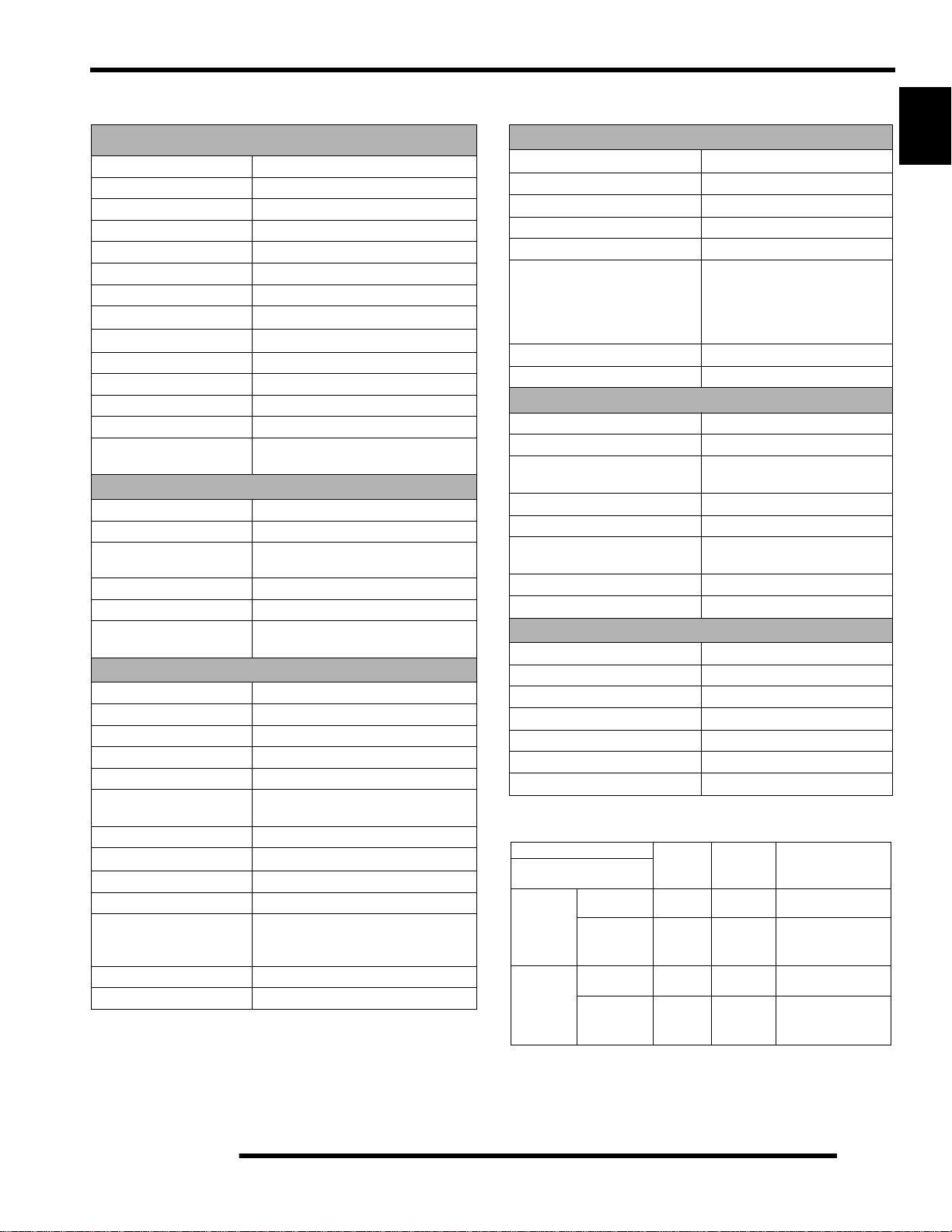
Table 1-4: Sportsman 700 EFI
General Specifications
Category Dimension / Capacity
Length 83 in./205.74 cm
Width 48 in./116.8 cm
Height 48 in./119.4 cm
Seat Height
Wheel Base 50.75 in./128.9 cm
Dry Weight 770 lbs./326.6 kg
Gross Vehicle Weight 1220 lbs. / 553 kg
Front Rack Capacity 100 lbs./45.4 kg
Rear Rack Capacity 200 lbs./90.7 kg
Towing Capacity 1500 lbs./680 kg
Body Style Spirit
Hitch Tongue Capacity 150 lbs./68 kg
34 in./86.4 cm
1.6
Page 11
GENERAL INFORMATION
Table 1-5: 2007 700 EFI Specifications
ENGINE
Platform Polaris Twin Cylinder
Engine Model Number EH068OLE025
Engine Displacement 683cc
Number of Cylinders 2
Bore & Stroke (mm) 80 x 68 mm
Compression Ratio 9.78:1
Compression Pressure 150-170 psi
Engine Idle Speed
Engine Max Operating Rpm
Cooling System / Capacity L i qu id - 3.2 qt / 3 ltr
Overheat Warning HOT on Instrument Cluster
Lubrication Pressurized Wet Sump
Oil Requirements / Capacity Polaris 0W-40 2 qt. / 1.9 ltr
Exhaust System Single Pipe USFS Approved
Fuel System
Fuel System Electronic Fuel Injection (EFI)
Fuel Pump (in tank assembly) 25L per hr. at 39 psi
Fuel Filter(s) 30 micron in Tank -
Fuel Injector(s) Bosch
EFI Controller Bosch MSE 1.1B
Fuel Capacity / Requirement 4.13 gal US / 15.6 liters
87 Octane (minimum) or 89 Oxygenated
Electrical
Alternator Output 500 w @ 6000 RPM
Lights : Pod 50 watts
Grill Two x 27 watts
Brake 8.26 watts
Tail 26.9 watts
Ignition System DC/CDI Ignition
Ignition Timing
Spark plug / Gap RC7YC / .035 in. / 0.9 mm
Battery / Amp Hr Lead Acid / 30 Amp Hr.
Circuit Breakers Fan 20 amp / Harness 20 amp /
Starting Electric
Instrument Cluster Analog Speedo w/ LCD
1150
100 RPM
6500 Rpm
10 micron in-line (replaceable)
13
° BTDC @ 1200 RPM
ECU 15 amp / Inst. Cluster /
Voltage Regulator 6 amp
200 Rpm
(unserviceable)
Table 1-6: 2007 700 EFI Specifications
Drivetrain
Transmission Type Drumshift - H/L/N/Rev/Park
Transmission Capacity 15 oz. / 445 ml
Front Gearcase Capacity- CH 8.97 / 265 ml
Rear Gearcase Capacity 5 oz. / 150 ml
Gear Ratio : Low
Rev
High
Front Drive
Rear Drive
Clutch Type PVT Non-EBS
Belt 3211113
7.49:1
5.11:1
2.70:1
3.82:1
3.10:1
Steering / Suspension
Front Suspension / Shock A-arm / MacPherson Strut
Front Travel 8.2 in. / 21 cm
Rear Suspension / Shock Progressive Rate Independent -
Coil - over shock
Rear Travel 9.5 in. / 24.13 cm
Ground Clearance 11.25 in. / 28.6 cm
Shock Preload Adjustment
Front / Rear
Turning Radius 76 in. / 193 cm unlocked
Toe Out 0-1/16 in / .0 - .159 mm
Front -Non Adjustable.
Rear - Ratchet Style- Std.
Wheels / Brakes
Wheel Size / Pattern - Front Steel 24 x 8-12 / 4-156
Wheel Size / Pattern - Rear Steel 24 x 11-12 / 4-156
Front Tire Size 24 x 8-12
Rear Tire Size 24 x 11-12
Recommended Air Pressure Front & Rear - 5 psi
Brake - Front Dual Hydraulic Disc
Brake - Rear Dual Hydraulic Disc
Table 1-7: 2007 700 EFI Clutching
Altitude
Meters
0-1800
(0-6000)
1800-3700
(6000-12000)
(Feet)
A07MH68
(STANDARD)
A07MH68
(STANDARD)
Shift
Weight
20-58
5631216
20-56
5631215
Drive Clutch
Spring
Grn/Blu
7041157
Grn/Blu
7041157
Driven Clutch Type
(Non-Adjustable)
STD - 1322514
STD - 1322514
1
1.7
Page 12
GENERAL INFORMATION
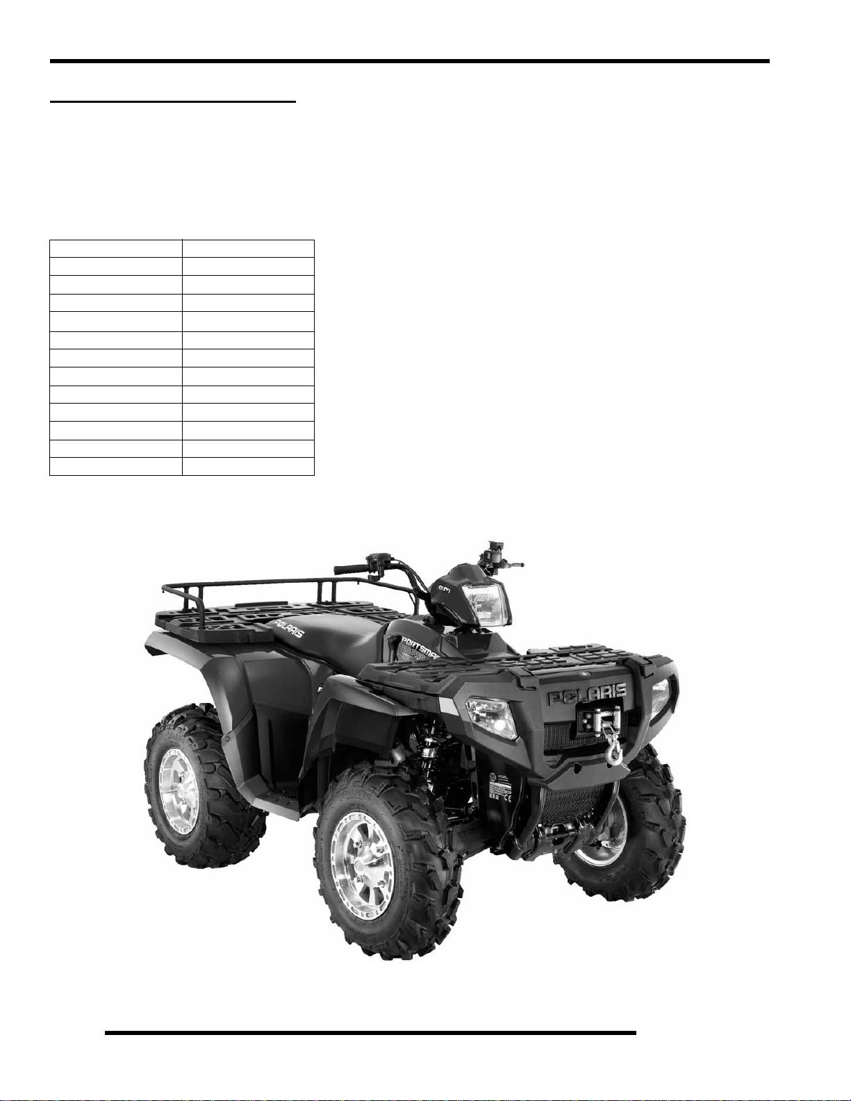
2007 SPORTSMAN 800 EFI
MODEL NUMBER: A07MH76AX, AY, AZ / A07MN76AQ, AF / A07MH76FA
(Standard) (Deluxe) (International)
ENGINE MODEL: EH076OLE
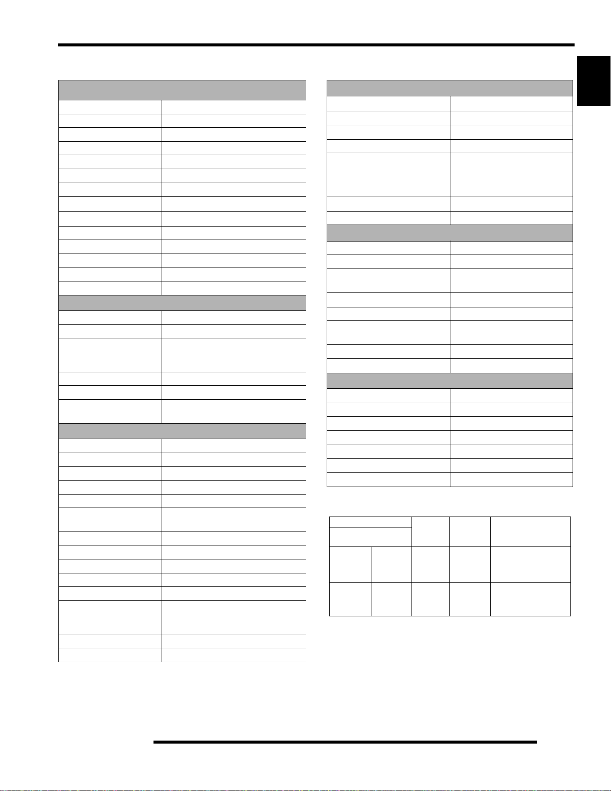
Table 1-8: Sportsman 800 EFI
General Specifications
Category Dimension / Capacity
Length 83 in./205.74 cm
Width 48 in./116.8 cm
Height 48 in./119.4 cm
Seat Height
Wheel Base 50.75 in./128.9 cm
Dry Weight 770 lbs./326.6 kg
Gross Vehicle Weight 1220 lbs. / 553 kg
Front Rack Capacity 100 lbs./45.4 kg
Rear Rack Capacity 200 lbs./90.7 kg
Towing Capacity 1500 lbs./680 kg
Body Style Spirit
Hitch Tongue Capacity 150 lbs./68 kg
34 in./86.4 cm
1.8
Deluxe Model Shown
Page 13
GENERAL INFORMATION
Table 1-9: 2007 800 EFI Specifications
ENGINE
Platform Polaris Twin Cylinder
Engine Model Number EH076OLE013
Engine Displacement 760cc
Number of Cylinders 2
Bore & Stroke (mm) 80 x 76.5 mm
Compression Ratio 10:1
Compression Pressure 150-200 psi
Engine Idle Speed
Engine Max Operating Rpm
Cooling System / Capacity Liquid - 3.2 qt/ 3 ltr.
Overheat Warning HOT on Instrument Cluster
Lubrication Pressurized Wet Sump
Oil Requirements / Capacity Polaris 0W-40 2 qt. / 1.9 liters
Exhaust System Dual Pipe / Silencer (Deluxe)
Fuel System
Fuel System Electronic Fuel Injection
Fuel Pump 25L per hour at 39 PSI
Fuel Filter(s) 30 micron in Tank -
Fuel Injector(s) Bosch
EFI Controller Bosch MSE 1.1B
Fuel Capacity / Requirement 4.13 gal US / 15.6 liters
87 Octane (minimum) or 89 Oxygenated
Electrical
Alternator Output 500 w @ 6000 RPM
Lights : Pod 30 watts
Grill Two x 27 watts
Brake 8.26 watts
Tail 26.9 watts
Worklights
(Deluxe Only)
Ignition System DC/CDI Ignition
Ignition Timing
Spark plug / Gap RC7YC/ .035 in. / 0.9 mm
Battery / Amp Hr Lead Acid / 30 Amp Hr
Circuit Breakers Fan 20 amp / Harness 20 amp /
Starting Electric
Instrument Cluster Analog Speedo w/ LCD
1150
100 RPM
6500 Rpm
Single Pipe / Silencer (Standard)
10 micron in Line (replaceable)
13
°BTDC @ 1200 RPM
ECU 15 amp / Inst. Cluster /
Voltage Regulator 6 amp
200 Rpm
(unserviceable)
2 x 13 watts
Table 1-10: 2007 800 EFI Specifications
Drivetrain
Transmission Type Drumshift - H/L/N/Rev/Park
Transmission Capacity 15 oz. / 450ml
Front Gearcase Capacity- CH 8.97 / 265 ml
Front Gearcase Capacity- ADC 9.3 / 275 ml
Rear Gearcase Capacity 5 oz. / 150ml
Gear Ratio : Low
Rev
High
Front Drive
Rear Drive
Clutch Type PVT (Std) EBS (Deluxe)
Belt 3211113
7.49:1
5.11:1
2.70:1
3.82:1
3.10:1
Steering / Suspension
Front Suspension / Shock A-arm / MacPherson Strut
Front Travel 8.2 in. / 21 cm
Rear Suspension / Shock Progressive Rate Independent -
Coil - over shock
Rear Travel 9.5 in. / 24.13 cm
Ground Clearance 11.25 in. / 28.6 cm
Shock Preload Adjustment
Front / Rear
Turning Radius 76 in. / 193 cm
Toe Out 0 - 1/16 in / .0 - .159 mm
Front -Non Adjustable.
Rear - Ratchet Style- Std.
Wheels / Brakes
Wheel Size / Pattern - Front 26 x 8 - 12 / 4-156
Wheel Size / Pattern - Rear 26 x 11 - 12 / 4-156
Front Tire Size 26 x 8 - 12
Rear Tire Size 26 x 11 - 12
Recommended Air Pressure Front - 5 psi & Rear - 5 psi
Brake - Front Dual Hydraulic Disc
Brake - Rear Dual Hydraulic Disc
T able 1-1 1: A07MH76A/A07MN76A Clutching
0-1800
(0-6000)
1800-3700
(6000-12000)
Altitude
Meters
(Feet)
A07MH76
(STANDARD)
A07MN76
(DELUXE)
(INTERNATIONAL)
A07MH76
(STANDARD)
A07MN76
(DELUXE)
(INTERNATIONAL)
Shift
Weight
20-62
5631700
20-62
w/
EBS
20-60
5631698
20-60
w/
EBS
Drive Clutch
Spring
Blu/Red
7043199
Grn/Blu
7041157
w/
EBS
Blu/Red
7043199
Grn/Blu
7041157
w/EBS
Driven Clutch Type
(Non-Adjustable)
STD - 1322514
EBS - 1322550
STD - 1322514
EBS - 1322550
1
1.9
Page 14
GENERAL INFORMATION
2007 SPORTSMAN X2 800 EFI
MODEL NUMBER: A07TH76AU, A07TN76AF
(Standard) (Deluxe)
ENGINE MODEL: EH076OLE
Table 1-12: Sportsman X2 800 EFI
General Specifications
Category Dimension / Capacity
Length 93 in./236.22 cm
Width 48 in./116.8 cm
Height 48 in./119.4 cm
Seat Height
Wheel Base 57 in./128.9 cm
Dry Weight Standard 839 lbs./380.5 kg
Gross Vehicle Weight 1500 lbs./680.3 kg
Front Rack/ Box Capacity 90 lbs./40.8 kg
Rear Box Capacity 400 lbs./181.4 kg
Towing Capacity 1500 lbs./680 kg
Body Style Spirit
Hitch Tongue Capacity 150 lbs./68 kg
34 in./86.4 cm
Deluxe 874 lbs./396 kg
1.10
Standard Model Shown
Page 15
GENERAL INFORMATION
Table 1-13: 2007 800 X2 EFI Specifications
ENGINE
Platform Polaris Twin Cylinder
Engine Model Number EH076OLE013
Engine Displacement 760cc
Number of Cylinders 2
Bore & Stroke (mm) 80 x 76.5 mm
Compression Ratio 10:1
Compression Pressure 150-200 psi
Engine Idle Speed
Engine Max Operating Rpm
Cooling System / Capacity Liquid - 3.4 qt/ 3.2 ltr.
Overheat Warning HOT on Instrument Cluster
Lubrication Pressurized Wet Sump
Oil Requirements / Capacity Polaris 0W-40 2 qt. / 1.9 liters
Exhaust System Single Pipe / Silencer
Fuel System
Fuel System Electronic Fuel Injection
Fuel Pump 25L per hour at 39 PSI
Fuel Filter(s) 30 micron in Tank -
Fuel Injector(s) Bosch
EFI Controller Bosch MSE 1.1B
Fuel Capacity / Requirement 6.0 gal US / 22.7 liters
87 Octane (minimum) or 89 Oxygenated
Electrical
Alternator Output 500 w @ 6000 RPM
Lights : Pod 50 watts
Grill Two x 37 watts
Tail 2 x 26.9 watts
Brake 2 x 8.26 watts
Worklights
(Deluxe Only)
Indicator Panel 1 watt
Ignition System DC/CDI Ignition
Ignition Timing Variable - ECU controlled
Spark plug / Gap RC7YC/ .035 in. / 0.9 mm
Battery / Amp Hr Lead Acid / 30 Amp Hr
Fuses Fan 20 amp / Harness 20 amp /
Starting Electric
Instrument Cluster Analog Speedo w/ LCD
1150
100 RPM
6500 Rpm
10 micron in Tank - (unserviceable)
10 micron in Line (replaceable)
ECU 15 amp / Inst. Cluster /
Voltage Regulator 6 amp
200 Rpm
(unserviceable)
2 x 13 watts
Table 1-14: 2007 800 X2 EFI Specifications
Drivetrain
Transmission Type Drumshift - H/L/N/Rev/Park
Transmission Capacity 32 oz. / 946.3ml
Front Gearcase Capacity- CH 8.97 / 265 ml
Front Gearcase Capacity- ADC 9.3 / 275 ml
Gear Ratio : Low
Rev
High
Front Drive
Clutch Type PVT w/ EBS (Standard and Deluxe)
Belt 3211113
23.91:1
21.74:1
8.28:1
3.82:1
Steering / Suspension
Front Suspension / Shock A-arm / MacPherson Strut
Front Travel 8.2 in. / 21 cm
Rear Suspension / Shock Progressive Rate Independent -
Coil - over shock
Rear Travel 8.75 in. / 22.22 cm
Ground Clearance 11.25 in. / 28.6 cm
Shock Preload Adjustment
Front / Rear
Turning Radius 82 in. / 208.2 cm
Toe Out 0 - 1/16 in / .0 - .159 mm
Front -Non Adjustable.
Rear - Ratchet Style- Std.
Wheels / Brakes
Wheel Size / Pattern - Front 25 x 8 - 12 / 4-156
Wheel Size / Pattern - Rear 25 x 11 - 12 / 4-156
Front Tire Size 25 x 8 - 12
Rear Tire Size 25 x 11 - 12
Recommended Air Pressure Front - 5 psi & Rear - 5 psi
Brake - Front Dual Hydraulic Disc
Brake - Rear Dual Hydraulic Disc
Table 1-15: 2007 800 X2 EFI Clutching
Altitude
Meters
0-1800
(0-6000)
1800-3700
(6000-12000)
(Feet)
A07TH76A
(STANDARD)
A07TN76A
(DELUXE)
A07TH76A
(STANDARD)
A07TN76A
(DELUXE)
Shift
Weight
20-62
w/
EBS
20-58
w/
EBS
Drive Clutch
Spring
Grn/Blu
7041157
w/EBS
Grn/Blu
7041157
w/EBS
Driven Clutch Type
(Non-Adjustable)
EBS - 1322550
EBS - 1322550
1
1.11
Page 16

GENERAL INFORMATION
MISC. NUMBERS/CHARTS
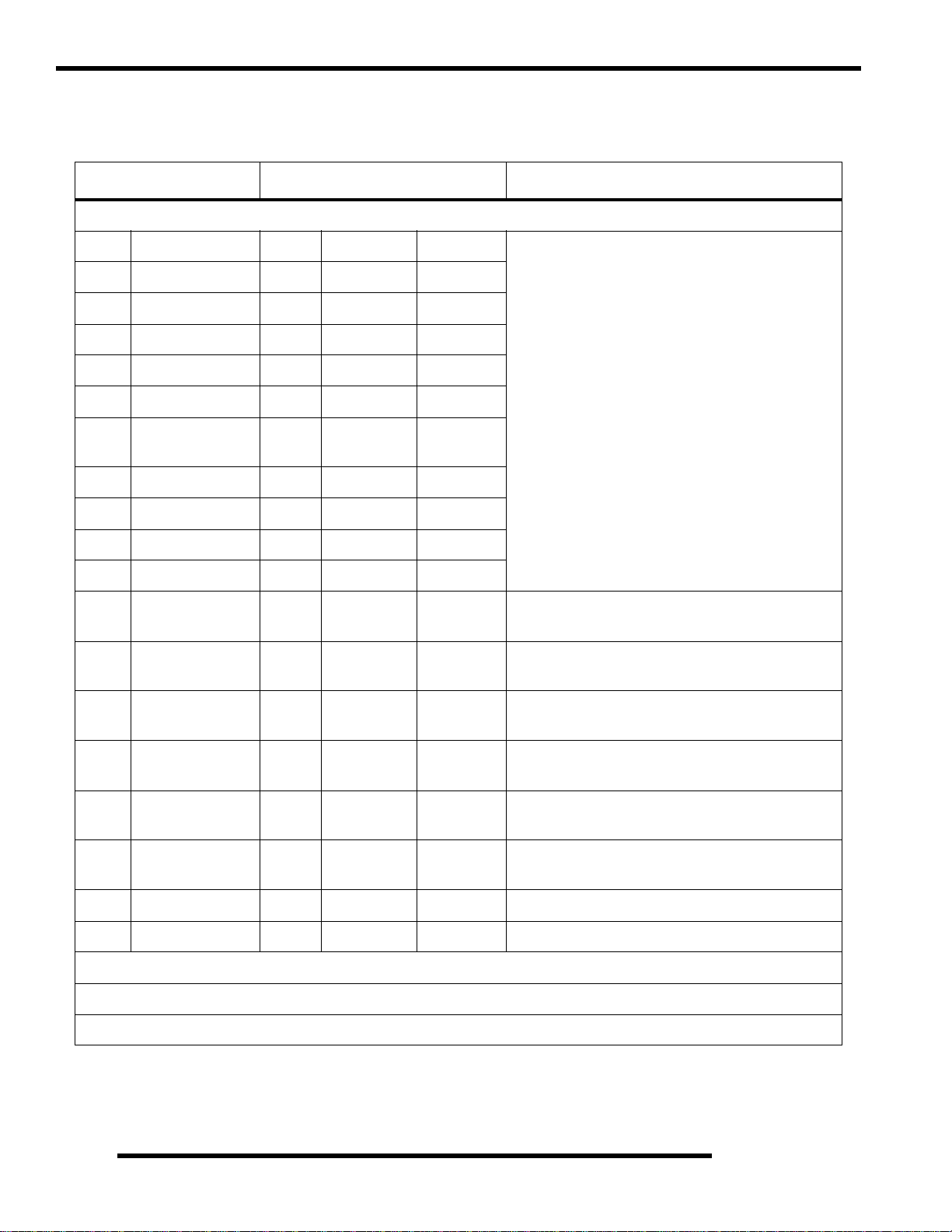
Standard Torque Specifications
The following torque specifications are to be used as a general guideline. FOR SPECIFIC TO RQUE V ALUES OF F A STENERS Refer to exploded
views in the appropriate section. There are exceptions in the steering, suspension, and engine sections.
Bolt Size Threads/In Grade 2 Grade 5 Grade 8
#10 - 24 . . . . . . . . . . . . . . . . . 27 (3.1) . . . . . . . . . 43 (5.0) . . . . . . . . 60 (6.9)
#10 - 32 . . . . . . . . . . . . . . . . . 31 (3.6) . . . . . . . . . 49 (5.6) . . . . . . . . 68 (7.8)
1/4 - 20 . . . . . . . . . . . . . . . . .5 (7). . . . . . . . . . . . 8 (11). . . . . . . . . . 12 (16)
1/4 - 28 . . . . . . . . . . . . . . . . .6 (8). . . . . . . . . . . . 10 (14). . . . . . . . . 14 (19)
5/16 - 18 . . . . . . . . . . . . . . . . . 11(15). . . . . . . . . . . 17 (23). . . . . . . . . 25 (35)
5/16 - 24 . . . . . . . . . . . . . . . . . 12(16) . . . . . . . . . . 19 (26). . . . . . . . . 29 (40)
3/8 - 16 . . . . . . . . . . . . . . . . . 20(27) . . . . . . . . . . 30 (40). . . . . . . . . 45 (62)
3/8 - 24 . . . . . . . . . . . . . . . . .23(32) . . . . . . . . . . 35 (48). . . . . . . . . 50 (69)
7/16 - 14 . . . . . . . . . . . . . . . . . 30(40) . . . . . . . . . . 50 (69). . . . . . . . . 70 (97)
7/16 - 20 . . . . . . . . . . . . . . . . . 35(48) . . . . . . . . . . 55 (76). . . . . . . . . 80 (110)
1/2 - 13 . . . . . . . . . . . . . . . . .50(69) . . . . . . . . . . 75 (104). . . . . . . . 110 (152)
1/2 - 20 . . . . . . . . . . . . . . . . .55(76) . . . . . . . . . . 90 (124). . . . . . . . 120 (166)
Metric / Torque
6 x 1.0. . . . . . . . . . 72-78 In.lbs.. . . . . . . . .8 x 1.25 14-18 ft.lbs. . . .10 x 1.25 26-30 ft.lbs.
Torque in. lbs. (Nm)
Torque ft. lbs. (Nm)*
SPECIAL TOOLS
Special tools may be required while servicing this vehicle. Some of the tools listed or depicted are mandatory , while other tools maybe
substituted with a similar tool, if available. Polaris recommends the use of Polaris Special Tools when servicing any Polaris product.
Dealers may order special tools through Polaris’ official tool supplier, SPX Corporation, 1-800-328-6657.
1.12
Page 17

GENERAL INFORMATION
SAE Tap Drill Sizes
Thread Size/ Drill Size Thread Size / Drill Size
#0-80 3/64 1/2-13 27/64
#1-64 53 1/2-20 29/64
#1-72 53 9/16-12 31/64
#2-56 51 9/16-18 33/64
#2-64 50 5/8-11 17/32
#3-48 5/64 5/8-18 37/64
#3-56 45 3/4-10 21/32
#4-40 43 3/4-16 11/16
#4-48 42 7/8-9 49/64
#5-40 38 7/8-14 13/16
#5-44 37 1-8 7/8
#6-32 36 1-12 59/64
#6-40 33 1 1/8-7 63/64
#8-32 29 1 1/8-12 1 3/64
#8-36 29 1 1/4-7 1 7/64
#10-24 24 1 1/4-12 1 11 /64
#10-32 21 1 1/2-6 1 11/32
#12-24 17 1 1/2-12 1 27 /64
#12-28 4.6mm 1 3/4-5 1 9/16
1/4-20 7 1 3/4-12 1 43/64
1/4-28 3 2-4 1/2 1 25/32
5/16-18 F 2-12 1 59/64
5/16-24 I 2 1/4-4 1/2 2 1/32
3/8-16 O 2 1/2-4 2 1/ 4
3/8-24 Q 2 3/4-4 2 1/ 2
7/16-14 U 3-4 2 3/4
7/16-20 25/64
Metric Tap Drill Sizes
Tap Size Drill Size
3x.50 #39 0.0995 3/32
3x.60 3/32 0.0937 3/32
4x.70 #30 0.1285 1/8
4x.75 1/8 0.125 1/8
5x.80 #19 0.166 11/64
5x.90 #20 0.161 5/32
6x1.00 #9 0.196 13/64
7x1.00 16/64 0.234 15/64
8x1.00 J 0.277 9/32
8x1.25 17/64 0.265 17/64
9x1.00 5/16 0.3125 5/16
9x1.25 5/16 0.3125 5/16
10x1.25 11/32 0.3437 11/32
10x1.50 R 0.339 11/32
11x1.50 3/8 0.375 3/8
12x1.50 13/32 0.406 13/32
12x1.75 13/32 0.406 13/32
Decimal
Equivalent
Nearest
Fraction
Decimal Equivalents
1/64 . . . . . . . . . . .. . . . . . . .0156
1/32 . . . . . . .. . . . . . . .0312 . . 1 mm= .0394"
3/64 . . . . . . . . . . .. . . . . . . .0469
1/16 . . . . . . .. . . . . . . .0625
5/64 . . . . . . . . . . .. . . . . . . .0781 . . 2 mm = .0787"
3/32 . . . . . . .. . . . . . . .0938
7/64 . . . . . . . . . . .. . . . . . . .1094 . . 3 mm =.1181"
1/8 . . . . . . . . .1250
9/64 . . . . . . . . . . .. . . . . . . .1406
5/32 . . . . . . .. . . . . . . .1563 . . 4 mm = .1575"
11/64 . . . . . . . . . . .. . . . . . . .1719
3/16 . . . . . . .. . . . . . . .1875 . . 5mm= .1969"
13/64 . . . . . . . . . . .. . . . . . . .2031
7/32 . . . . . . .. . . . . . . .2188
15/64 . . . . . . . . . . .. . . . . . . .2344 . . 6 mm = .2362"
1/4 . . . . . . . . .25
17/64 . . . . . . . . . . .. . . . . . . .2656 . . 7 mm = .2756"
9/32 . . . . . . .. . . . . . . .2813
19/64 . . . . . . . . . . .. . . . . . . .2969
5/16 . . . . . . .. . . . . . . .3125 . . 8mm= .3150"
21/64 . . . . . . . . . . .. . . . . . . .3281
11/32 . . . . . .. . . . . . . .3438 . . 9 mm = .3543"
23/64 . . . . . . . . . . .. . . . . . . .3594
3/8 . . . . . . . . .375
25/64 . . . . . . . . . . .. . . . . . . .3906 . . 10 mm = .3937"
13/32 . . . . . .. . . . . . . .4063
27/64 . . . . . . . . . . .. . . . . . . .4219 . . 11 mm =.4331"
7/16 . . . . . . .. . . . . . . .4375
29/64 . . . . . . . . . . .. . . . . . . .4531
15/32 . . . . . .. . . . . . . .4688 . . 12 mm = .4724"
31/64 . . . . . . . . . . .. . . . . . . .4844
1/2 . . . . . . . . .5 . . . . . . . . . . . 13mm = .5118"
33/64 . . . . . . . . . . .. . . . . . . .5156
17/32 . . . . . .. . . . . . . .5313
35/64 . . . . . . . . . . .. . . . . . . .5469 . . 14 mm = .5512"
9/16 . . . . . . .. . . . . . . .5625
37/64 . . . . . . . . . . .. . . . . . . .5781 . . 15 mm = .5906"
19/32 . . . . . .. . . . . . . .5938
39/64 . . . . . . . . . . .. . . . . . . .6094
5/8 . . . . . . . . .625 . . . . . . . . . 16mm=. 6299"
41/64 . . . . . . . . . . .. . . . . . . .6406
21/32 . . . . . .. . . . . . . .6563 . . 17 mm =.6693"
43/64 . . . . . . . . . . .. . . . . . . .6719
11/16 . . . . . .. . . . . . . .6875
45/64 . . . . . . . . . . .. . . . . . . .7031 . . 18 mm = .7087"
23/32 . . . . . .. . . . . . . .7188
47/64 . . . . . . . . . . .. . . . . . . .7344 . . 19 mm = .7480"
3/4 . . . . . . . . .75
49/64 . . . . . . . . . . .. . . . . . . .7656
25/32 . . . . . .. . . . . . . .7813 . . 20 mm = .7874"
51/64 . . . . . . . . . . .. . . . . . . .7969
13/16 . . . . . .. . . . . . . .8125 . . 21 mm =.8268"
53/64 . . . . . . . . . . .
27/32 . . . . . .. . . . . . . .8438
55/64 . . . . . . . . . . .. . . . . . . .8594 . . 22 mm = .8661"
7/8 . . . . . . . . .875
57/64 . . . . . . . . . . .. . . . . . . .8906 . . 23 mm = .9055"
29/32 . . . . . .. . . . . . . .9063
59/64 . . . . . . . . . . .. . . . . . . .9219
15/16 . . . . . .. . . . . . . .9375 . . 24 mm = .9449"
61/64 . . . . . . . . . . .. . . . . . . .9531
31/32 . . . . . .. . . . . . . .9688 . . 25 mm = .9843"
63/64 . . . . . . . . . . .. . . . . . . .9844
1. . . . . . . . . . 1.0
. . . . . . . .8281
1
1.13
Page 18

GENERAL INFORMATION
Conversion Table
Unit of Measure Multiplied by Converts to
ft. lbs. x 12 = in. lbs.
in. lbs. x .0833 = ft. lbs.
ft. lbs. x 1.356 = Nm
in. lbs. x .0115 = kg-m
Nm x .7376 = ft. lbs.
kg-m x 7.233 = ft. lbs.
kg-m x 86.796 = in. lbs.
kg-m x 10 = Nm
in. x 25.4 =mm
mm x .03937 = in.
in. x 2.54 = cm
mile (mi.) x 1.6 = km
km x .6214 = mile (mi.)
Ounces (oz.) x 28.35 = Grams (g)
Fluid Ounces (fl. oz.) x 29.57 = Cubic Centimeters (cc)
Cubic Centimeters (cc) x .03381 = Fluid Ounces (fl. oz.)
Grams (g) x 0.035 = Ounces (oz.)
lb. x .454 = kg
kg x 2.2046 = lb.
Cubic inches (cu. in) x 16.387 = Cubic centimeters (cc)
Cubic centimeters (cc) x 0.061 = Cubic inches (cu. in)
Imperial pints (Imp pt.) x 0.568 = Liters (l)
Liters (l) x 1.76 = Imperial pints (Imp pt.)
Imperial quarts (Imp qt.) x 1.137 = Liters (l)
Liters (l) x 0.88 = Imperial quarts (Imp qt.)
Imperial quarts (Imp qt.) x 1.201 = US quarts (US qt.)
US quarts (US qt.) x 0.833 = Imperial quarts (Imp qt.)
US quarts (US qt.) x 0.946 = Liters (l)
Liters (l) x 1.057 = US quarts (US qt.)
US gallons (US gal) x 3.785 =Liters (l)
Liters (l) x 0.264 = US gallons (US gal)
Pounds - force per square inch (psi) x 6.895 = Kilopascals (kPa)
Kilopascals (kPa) x 0.145 = Pounds - force per square inch (psi)
Kilopascals (kPa) x 0.01 = Kilograms - force per square cm
Kilograms - force per square cm x 98.1 = Kilopascals (kPa)
(3.14)xR
2
x H (height) = Cylinder Volume
°C to °F: 9 (°C + 40) 5 - 40 = °F
°F to °C: 5 (°F + 40)
9 - 40 = °C
1.14
Page 19

Glossary Of Terms
GENERAL INFORMATION
ABDC: After bottom dead center.
ACV: Alternating current voltage.
ADC: Active Descent Control. Engages front wheels for 4-wheel EBS.
Alternator: Electrical generator producing voltage alternating current.
ATDC: After top dead center.
BBDC: Before bottom dead center.
BDC: Bottom dead center.
BTDC: Before top dead center.
CC: Cubic centimeters.
Center Distance: Distance between center of crankshaft and center of driven clutch shaft.
Chain Pitch: Distance between chain link pins (No. 35 = 3/8" or 1 cm). Polaris measures chain length in number of pitches.
CI: Cubic inches.
Clutch Buttons: Plastic bushings which aid rotation of the movable sheave in the drive and driven clutch.
Clutch Offset: Drive and driven clutches are offset so that drive belt will stay nearly straight as it moves along the clutch face.
Clutch Weights: Three levers in the drive clutch which relative to their weight, profile and engine RPM cause the drive clutch to close and
grip the drive belt.
Crankshaft Run-Out: Run-out or "bend" of crankshaft measured with a dial indicator while crankshaft is supported between centers on V
blocks or resting in crankcase. Measure at various points especially at PTO.
CVT: Centrifugal Variable Transmission (Drive Clutch System)
DCV: Direct current voltage.
Dial Bore Gauge: A cylinder measuring instrument which uses a dial indicator . Good for showing t aper and out-of-round in the cylinder bore.
EBS: Engine Braking System. Uses engine compression to slow the ATV without the use of hydraulic brakes.
Electrical Open: Open circuit. An electrical circuit which isn't complete.
Electrical Short: Short circuit. An electrical circuit which is completed before the current reaches the intended load. (i .e. a bare wire touchi ng
the chassis).
End Seals: Rubber seals at each end of the crankshaft.
Engagement RPM: Engine RPM at which the drive clutch engages to make contact with the drive belt.
ft.: Foot/feet.
Foot Pound: Ft. lb. A force of one pound at the end of a lever one foot in length, applied in a rotational direction.
g: Gram. Unit of weight in the metric system.
gal.: Gallon.
ID: Inside diameter.
in.: Inch/inches.
Inch Pound: In. lb. 12 in. lbs. = 1 ft. lb.
2
: Kilograms per square centimeter.
kg/cm
kg-m: Kilogram meters.
Kilogram/meter: A force of one kilogram at the end of a lever one meter in length, applied in a rotational direction.
l or ltr: Liter.
2
: Pounds per square inch.
lbs/in
Left or Right Side: Always referred to based on normal operating position of the driver.
m: Meter/meters.
Mag: Magneto.
Magnetic Induction: As a conductor (coil ) is moved through a magnetic field, a voltage wil l be generated in the winding s. Mechanical energy
is converted to electrical energy in the stator.
mi.: Mile/miles.
mm: Millimeter. Unit of length in the metric system. 1 mm = approximately .0 40".
Nm: Newton meters.
OD: Outside diameter.
Ohm: The unit of electrical resistance opposing current flow.
oz.: Ounce/ounces.
Piston Clearance: Total distance between piston and cylinder wall.
psi.: Pounds per square inch.
PTO: Power take off.
qt.: Quart/quarts.
Regulator: Voltage regulator. Regulates battery charging system output at approximately 14.5 DCV as engine RPM increases.
Reservoir Tank: The fill tank in the liquid cooling system.
Resistance: In the mechanical sense, friction or load. In the electrical sense, ohms, resulting in energy conversion to heat.
RPM: Revolutions per minute.
Seized Piston: Galling of the sides of a piston. Usually there is a transfer of aluminum from the pis ton onto the cylinder wall.
Possible causes: 1) improper lubrication; 2) excessive temperatures; 3) insufficient piston clearance; 4) stuck piston rings.
Stator Plate: The plate mount ed under the flywheel supporting the battery charging coils.
TDC: Top dead center. Piston's most outward travel from crankshaft.
Volt: The unit of measure for electrical pressure of electromotive force. Measured by a voltmeter in parallel with the circuit.
Watt: Unit of electrical power. Watts = amperes x volts.
WOT: Wide open throttle.
1
1.15
Page 20

GENERAL INFORMATION
NOTES
1.16
Page 21

MAINTENANCE
CHAPTER 2
MAINTENANCE
MAINTENANCE. . . . . . . . . . . . . . . . . . . . . . . . . . . . . . . . . . . . . . . . . . . . . . . . . . . . . . . . . 2.3
OVERVIEW. . . . . . . . . . . . . . . . . . . . . . . . . . . . . . . . . . . . . . . . . . . . . . . . . . . . . . . . . . . .2.3
PERIODIC MAINTENANCE CHART . . . . . . . . . . . . . . . . . . . . . . . . . . . . . . . . . . . . . . . .2.4
LUBRICATION / FLUIDS. . . . . . . . . . . . . . . . . . . . . . . . . . . . . . . . . . . . . . . . . . . . . . . . . . 2.7
GENERAL COMPONENT LOCATIONS. . . . . . . . . . . . . . . . . . . . . . . . . . . . . . . . . . . . . .2.7
POLARIS LUBRICANTS, MAINTENANCE AND SERVICE PRODUCTS . . . . . . . . . . . .2.8
POLARIS LUBRICANT SYMBOL IDENTIFICATION. . . . . . . . . . . . . . . . . . . . . . . . . . . .2.9
PRE-RIDE / DAILY INSPECTION . . . . . . . . . . . . . . . . . . . . . . . . . . . . . . . . . . . . . . . . . .2.9
LUBRICATION / GREASE POINTS . . . . . . . . . . . . . . . . . . . . . . . . . . . . . . . . . . . . . . . .2.10
FRONT GEARCASE LUBRICATION. . . . . . . . . . . . . . . . . . . . . . . . . . . . . . . . . . . . . . .2.11
TRANSMISSION LUBRICATION. . . . . . . . . . . . . . . . . . . . . . . . . . . . . . . . . . . . . . . . . .2.12
ADC DIFFERENTIAL HYDRAULIC CIRCUIT FLUID CHANGE. . . . . . . . . . . . . . . . . . .2.13
VEHICLE INSPECTION. . . . . . . . . . . . . . . . . . . . . . . . . . . . . . . . . . . . . . . . . . . . . . . . . . 2.13
SHIFT LINK ROD AND THROTTLE INSPECTION . . . . . . . . . . . . . . . . . . . . . . . . . . . .2.13
THROTTLE INSPECTION . . . . . . . . . . . . . . . . . . . . . . . . . . . . . . . . . . . . . . . . . . . . . . .2.14
THROTTLE CABLE / ELECTRONIC THROTTLE CONTROL ADJUSTMENT . . . . . . .2.14
FUEL SYSTEM. . . . . . . . . . . . . . . . . . . . . . . . . . . . . . . . . . . . . . . . . . . . . . . . . . . . . . . .2.15
VENT LINES. . . . . . . . . . . . . . . . . . . . . . . . . . . . . . . . . . . . . . . . . . . . . . . . . . . . . . . . . .2.15
COMPRESSION TEST. . . . . . . . . . . . . . . . . . . . . . . . . . . . . . . . . . . . . . . . . . . . . . . . . .2.15
ENGINE MOUNTS . . . . . . . . . . . . . . . . . . . . . . . . . . . . . . . . . . . . . . . . . . . . . . . . . . . . .2.16
SPARK PLUG. . . . . . . . . . . . . . . . . . . . . . . . . . . . . . . . . . . . . . . . . . . . . . . . . . . . . . . . .2.16
ACTIVE DESCENT CONTROL (ADC) RESERVIOR LEVEL. . . . . . . . . . . . . . . . . . . . . 2.16
BATTERY MAINTENANCE . . . . . . . . . . . . . . . . . . . . . . . . . . . . . . . . . . . . . . . . . . . . . .2.17
COOLING SYSTEM. . . . . . . . . . . . . . . . . . . . . . . . . . . . . . . . . . . . . . . . . . . . . . . . . . . .2.17
COOLANT STRENGTH / TYPE. . . . . . . . . . . . . . . . . . . . . . . . . . . . . . . . . . . . . . . . . . .2.18
COOLING HOSES . . . . . . . . . . . . . . . . . . . . . . . . . . . . . . . . . . . . . . . . . . . . . . . . . . . . .2.18
RADIATOR. . . . . . . . . . . . . . . . . . . . . . . . . . . . . . . . . . . . . . . . . . . . . . . . . . . . . . . . . . .2.18
COOLING SYSTEM PRESSURE TEST. . . . . . . . . . . . . . . . . . . . . . . . . . . . . . . . . . . . .2.18
RESERVOIR LEVEL INSPECTION . . . . . . . . . . . . . . . . . . . . . . . . . . . . . . . . . . . . . . . .2.18
RADIATOR COOLANT LEVEL. . . . . . . . . . . . . . . . . . . . . . . . . . . . . . . . . . . . . . . . . . . .2.19
AIR FILTER SERVICE . . . . . . . . . . . . . . . . . . . . . . . . . . . . . . . . . . . . . . . . . . . . . . . . . .2.19
AIR BOX SEDIMENT TUBE. . . . . . . . . . . . . . . . . . . . . . . . . . . . . . . . . . . . . . . . . . . . . .2.20
ENGINE BREATHER . . . . . . . . . . . . . . . . . . . . . . . . . . . . . . . . . . . . . . . . . . . . . . . . . . .2.20
PVT INSPECTION / DRYING PROCEDURE. . . . . . . . . . . . . . . . . . . . . . . . . . . . . . . . .2.21
ENGINE GROUND. . . . . . . . . . . . . . . . . . . . . . . . . . . . . . . . . . . . . . . . . . . . . . . . . . . . .2.21
ENGINE OIL LEVEL. . . . . . . . . . . . . . . . . . . . . . . . . . . . . . . . . . . . . . . . . . . . . . . . . . . .2.21
OIL/FILTER CHANGE . . . . . . . . . . . . . . . . . . . . . . . . . . . . . . . . . . . . . . . . . . . . . . . . . .2.22
STEERING INSPECTION. . . . . . . . . . . . . . . . . . . . . . . . . . . . . . . . . . . . . . . . . . . . . . . .2.23
TIE ROD / STEERING . . . . . . . . . . . . . . . . . . . . . . . . . . . . . . . . . . . . . . . . . . . . . . . . . .2.23
CAMBER/CASTER. . . . . . . . . . . . . . . . . . . . . . . . . . . . . . . . . . . . . . . . . . . . . . . . . . . . .2.23
WHEEL ALIGNMENT. . . . . . . . . . . . . . . . . . . . . . . . . . . . . . . . . . . . . . . . . . . . . . . . . . .2.24
TOE ALIGNMENT. . . . . . . . . . . . . . . . . . . . . . . . . . . . . . . . . . . . . . . . . . . . . . . . . . . . . .2.24
EXHAUST PIPE . . . . . . . . . . . . . . . . . . . . . . . . . . . . . . . . . . . . . . . . . . . . . . . . . . . . . . .2.25
BRAKE SYSTEM INSPECTION. . . . . . . . . . . . . . . . . . . . . . . . . . . . . . . . . . . . . . . . . . .2.25
BRAKE PADS. . . . . . . . . . . . . . . . . . . . . . . . . . . . . . . . . . . . . . . . . . . . . . . . . . . . . . . . .2.26
BRAKE HOSE INSPECTION . . . . . . . . . . . . . . . . . . . . . . . . . . . . . . . . . . . . . . . . . . . . .2.26
AUXILIARY (REAR) BRAKE TEST . . . . . . . . . . . . . . . . . . . . . . . . . . . . . . . . . . . . . . . .2.26
AUXILIARY BRAKE ADJUSTMENT. . . . . . . . . . . . . . . . . . . . . . . . . . . . . . . . . . . . . . . .2.27
SUSPENSION: SPRING PRELOAD ADJUSTMENT. . . . . . . . . . . . . . . . . . . . . . . . . . .2.27
FRONT SUSPENSION. . . . . . . . . . . . . . . . . . . . . . . . . . . . . . . . . . . . . . . . . . . . . . . . . .2.27
REAR SUSPENSION . . . . . . . . . . . . . . . . . . . . . . . . . . . . . . . . . . . . . . . . . . . . . . . . . . .2.27
CV SHAFT BOOT INSPECTION . . . . . . . . . . . . . . . . . . . . . . . . . . . . . . . . . . . . . . . . . .2.27
ATV CONTROLS . . . . . . . . . . . . . . . . . . . . . . . . . . . . . . . . . . . . . . . . . . . . . . . . . . . . . .2.27
WHEEL INSPECTION . . . . . . . . . . . . . . . . . . . . . . . . . . . . . . . . . . . . . . . . . . . . . . . . . .2.28
2
2.1
Page 22

MAINTENANCE
WHEEL REMOVAL: FRONT OR REAR . . . . . . . . . . . . . . . . . . . . . . . . . . . . . . . . . . . . 2.28
WHEEL INSTALLATION . . . . . . . . . . . . . . . . . . . . . . . . . . . . . . . . . . . . . . . . . . . . . . . .2.28
TIRE PRESSURE. . . . . . . . . . . . . . . . . . . . . . . . . . . . . . . . . . . . . . . . . . . . . . . . . . . . . . 2.29
TIRE INSPECTION. . . . . . . . . . . . . . . . . . . . . . . . . . . . . . . . . . . . . . . . . . . . . . . . . . . . . 2.29
FRAME, NUTS, BOLTS, FASTENERS . . . . . . . . . . . . . . . . . . . . . . . . . . . . . . . . . . . . .2.29
FRONT / REAR STORAGE COMPARTMENTS . . . . . . . . . . . . . . . . . . . . . . . . . . . . . .2.29
WARN“WINCH OPERATION (IF EQUIPPED). . . . . . . . . . . . . . . . . . . . . . . . . . . . . . . . 2.30
CLEANING AND STORAGE OF ATV . . . . . . . . . . . . . . . . . . . . . . . . . . . . . . . . . . . . . . 2.32
2.2
Page 23

MAINTENANCE
MAINTENANCE
Overview
Careful periodic maintenance will help keep your vehicle in the safest, most reliable condition. Inspection, adjustment and
lubrication of important components are explained in the periodic maintenance chart.
Inspect, clean, lubricate, adjust and replace parts as necessary . When inspection reveals the need for replacement parts, use genuine
Polaris parts available from your Polaris dealer.
NOTE: Service and adjustments are critical. If you're not familiar with safe service and adjustment procedures, have a qualified
dealer perform these operations.
Maintenance intervals in the following chart are based upon average riding conditions and an average vehicle speed of approximately
10 miles per hour. Vehicles subjected to severe use must be inspected and serviced more frequently.
• Frequent immersion in mud, water or sand
• Racing or race-style high RPM use
• Prolonged low speed, heavy load operation
• Extended idle
• Short trip cold weather operation
Pay special attention to the oil level. A rise in oil level during cold weather can indicate contaminants collecting in the oil sump or
crankcase. Change oil immediately if the oil level begins to rise. Monitor the oil level, and if it continues to rise, discontinue use
and determine the cause.
Maintenance Chart Key
The following symbols denote potential items to be aware of during maintenance:
= CAUTION: Due to the nature of these adjustments, it is recommended this service be performed by an authorized
Polaris dealer.
= SEVERE USE ITEM --If vehicle is subjected to severe use, decrease interval by 50% (Sever e Use is defined as frequent
vehicle immersion in mud, water or sand, racing or race-style high rpm use, prolonged low speed - heavy load operation or
extended idle. More preventative maintenance is required under these conditions. Fluid changes, cable, chain and chassis
lubrication are required more frequently. For engine oil, short trip cold weather riding also constitutes severe use. Pay
special attention to oil level. A rising oil level in cold weather can indicate contaminants collecting in the oil sump or
crankcase. Change oil immediately and monitor level. If oil level begins to rise, discontinue use and determine cause.)
2
E = Emission Control System Service (California).
NOTE: Inspection may reveal the need for replacement parts. Always use genuine Polaris parts.
WARNING: Improperly performing the procedures marked with a could result in component failure and lead to serious injury
or death. Have an authorized Polaris dealer perform these services.
2.3
Page 24
MAINTENANCE
Periodic Maintenance Chart
Table 2-1: REQUIRED MAINTENANCE INTERVALS
ITEM MAINTENANCE INTERVAL REMARKS
Hours Calendar Miles (KM)
Steering -- Pre-Ride --
Front Suspension -- Pre-Ride --
Rear Suspension -- Pre-Ride --
Tires -- Pre-Ride --
ADC Fluid Level -- Pre-Ride --
Brake Fluid Level -- Pre-Ride --
, E Engine Oil Level -- Pre-Ride --
, E
, E
, E
Brake Lever
Travel
Brake Systems -- Pre-Ride -Wheels/Fasteners -- Pre-Ride -Frame Fasteners -- Pre-Ride --
Air filter,
pre-filter
Air Box Sediment
Tube
Coolant
(if applicable)
Head lamp/tail
lamp
Air filter, main
element
Recoil housing
(if applicable)
-- Pre-Ride --
-- Daily -- Inspect; clean often
-- Daily -- Drain deposits when visible
-- Daily -- Check level daily, change coolant every 2 years
-- Daily -- Check operation; apply dielectric grease if replacing
-- Weekly -- Inspect; replace as needed
-- Weekly --
Make adjustments as needed.
Drain water as needed, check often if operating in
wet conditions
, E Brake Pad Wear 10 H Month ly 60 (100) Inspect periodically
Battery 20 H Monthly 125 (200) Check terminals; clean; test
= Perform these procedures more often for vehicles subjected to severe use.
E = Emission Control System Service (California)
= Have an authorized Polaris Dealer perform these services.
2.4
Page 25

Table 2-1: REQUIRED MAINTENANCE INTERVALS
ITEM MAINTENANCE INTERVAL REMARKS
Hours Calendar Miles (KM)
MAINTENANCE
Transmission Oil 25 H Monthly 155 (250) Inspect level; change yearly
, E
, E
Steering 50 H 6 M 310 (500) Lubricate
Front Suspension 50 H 6 M 310 (500) Lubricate
Rear Suspension 50 H 6 M 310 (500) Lubricate
Front gearcase oil
(if equipped)
Middle gearcase
oil (if equipped)
Rear gearcase oil
(if equipped)
Engine breather
filter (if
equipped)
Engine oil change
(break-in)
General
lubrication
Shift Linkage 50 H 6 M 310 (500) Inspect, lubricate, adjust
25 H Monthly 155 (250) Inspect level; change yearly
25 H Monthly 155 (250) Inspect level; change yearly
25 H Monthly 155 (250) Inspect level; change yearly
25 H Monthly 155 (250) Inspect; replace if necessary
25 H 1 M 1 55 (250) Perform a break-in oil change at one month
50 H 3 M 3 10 (500) Lubricate all fittings, pivots, cables, etc.
2
, E
E Air intake ducts 50 H 6 M 310 (500) Inspect ducts for proper sealing/air leaks
, E
, E Oil filter change 100 H 6 M 620 (1000) Replace with oil change
, E
, E Valve Clearance 100 H 12 M 620 (1000) Inspect ;
= Perform these procedures more often for vehicles subjected to severe use.
E = Emission Control System Service (California)
= Have an authorized Polaris Dealer perform these services.
Throttle Cable/
ETC Switch
Drive belt 50 H 6 M 310 (500) Inspect; adjust; replace as needed
Cooling system
(if applicable)
Engine Oil
Change
Oil tank vent hose
(iff applicable)
50 H 6 M 310 (500) Inspect; adjust; lubricate; replace if necessary
50 H 6 M 3 10 (500)
100 H 6 M 620 (1000) Perform a break-in oil change at 25 hours/one month
100 H 12 M 620 (1000) Inspect routing, condition
Inspect coolant strength seasonally; pressure test
system yearly
2.5
Page 26

MAINTENANCE
Table 2-1: REQUIRED MAINTENANCE INTERVALS
ITEM MAINTENANCE INTERVAL REMARKS
Hours Calendar Miles (KM)
, E Fuel system 1 00 H 12 M 620 (1000)
, E Fuel filter 100 H 12 M 620 (1000) Replace yearly
Engine mounts 100 H 12 M 620 (1000) Inspect
, E Spark Plug 100 H 12 M 620 (1000) Inspect; replace as needed
, E Ignition Timing 100 H 1 2 M 620 (1000) Inspect
Wiring 100 H 12 M 620 (1000)
Radiator
(if applicable)
Cooling hoses
(if applicable)
Exhaust
muffler/pipe
Clutches
(drive & driven)
Front wheel
bearings
100 H 12 M 620 (1000) Inspect; clean external surfaces
100 H 12 M 620 (1000) Inspect for leaks
100 H 12 M 620 (1000) Inspect
100 H 12 M 620 (1000) Inspect; clean; replace worn parts
100 H 12 M
1000
(1600)
Check for leaks at tank cap, lines, fuel pump, filter,
pump, injectors; replace lines every two years
Inspect for wear, routing, security; apply dielectric
grease to connectors subjected to water, mud, etc.
Inspect; replace as needed
Brake fluid 200 H 24 M
ADC fluid 200 H 24 M
Spark arrestor 300 H 36 M
E Idle Speed ---- Adjust as needed
Toe Adjustment ---- Inspect periodically; adjust when parts are replaced
,
= Perform these procedures more often for vehicles subjected to severe use.
E = Emission Control System Service (California)
= Have an authorized Polaris Dealer perform these services.
Auxiliary brake ---- Inspect daily, adjust as needed
Headlight aim ---- Adjust as needed
1240
(1000)
1240
(1000)
1860
(3000)
Change every two years
Change every two years
Clean out
2.6
Page 27
LUBRICATION / FLUIDS
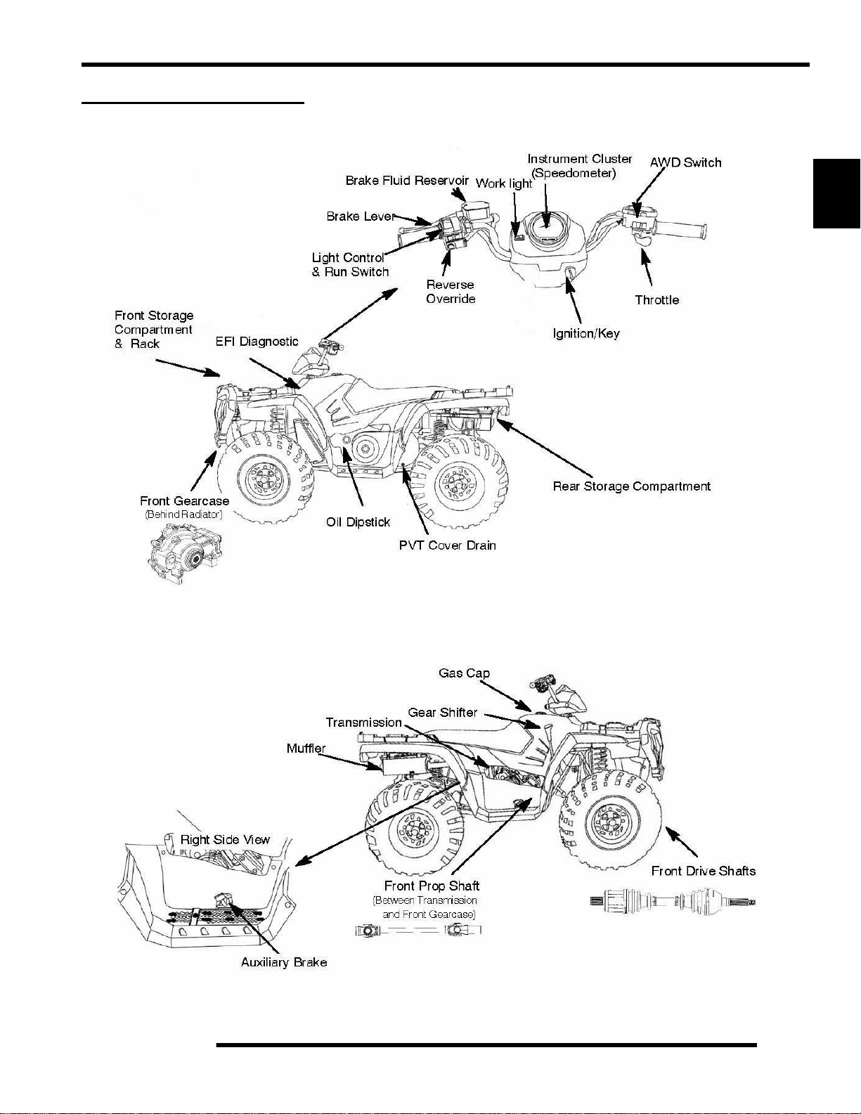
SPORTSMAN Component Locations
MAINTENANCE
(Deluxe)
2
(Sportsman Only)
2.7
Page 28
MAINTENANCE
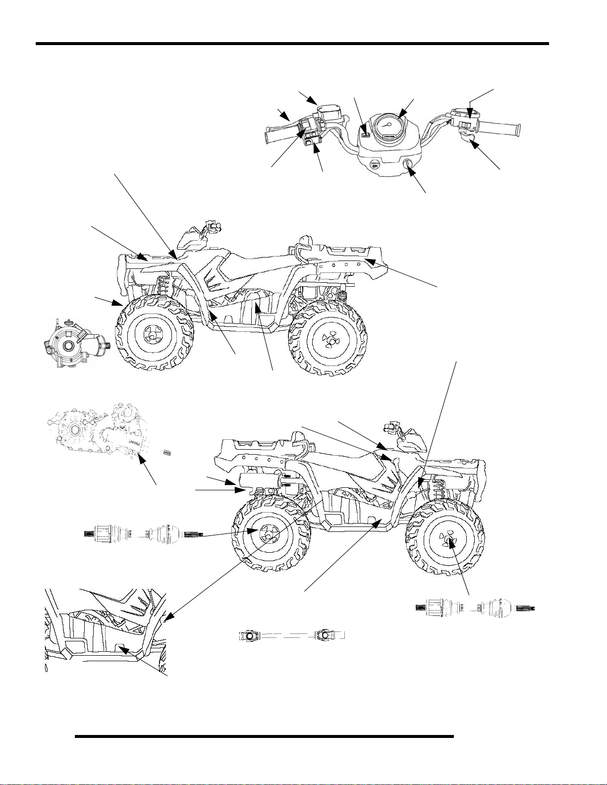
SPORTSMAN X2 Component Locations
Brake Fluid Reservoir
Brake Lever
Worklight
Instrument Cluster
(Speedometer)
AWD/Turf Switch
Diagnostic
Port (under access panel)
Front St orage
Compartment
& Rack
Front Demand
Drive Unit
(Behind Radiator)
Light Control
& Run Switch
Oil Dipstick
PVT Cover
Gear Shifter
Reverse
Override
Gas Cap
Throttle
Ignition/Key
Rear Dump Box / Passenger Area
Battery (Under Tank)
2.8
Transmission
Rear Drive CV Shafts
Right Side View
Muffler
Auxiliary Brake
Front Prop Shaft
(Between Transmission
and Front Gearcase)
Front Drive CV Shafts
Page 29
MAINTENANCE
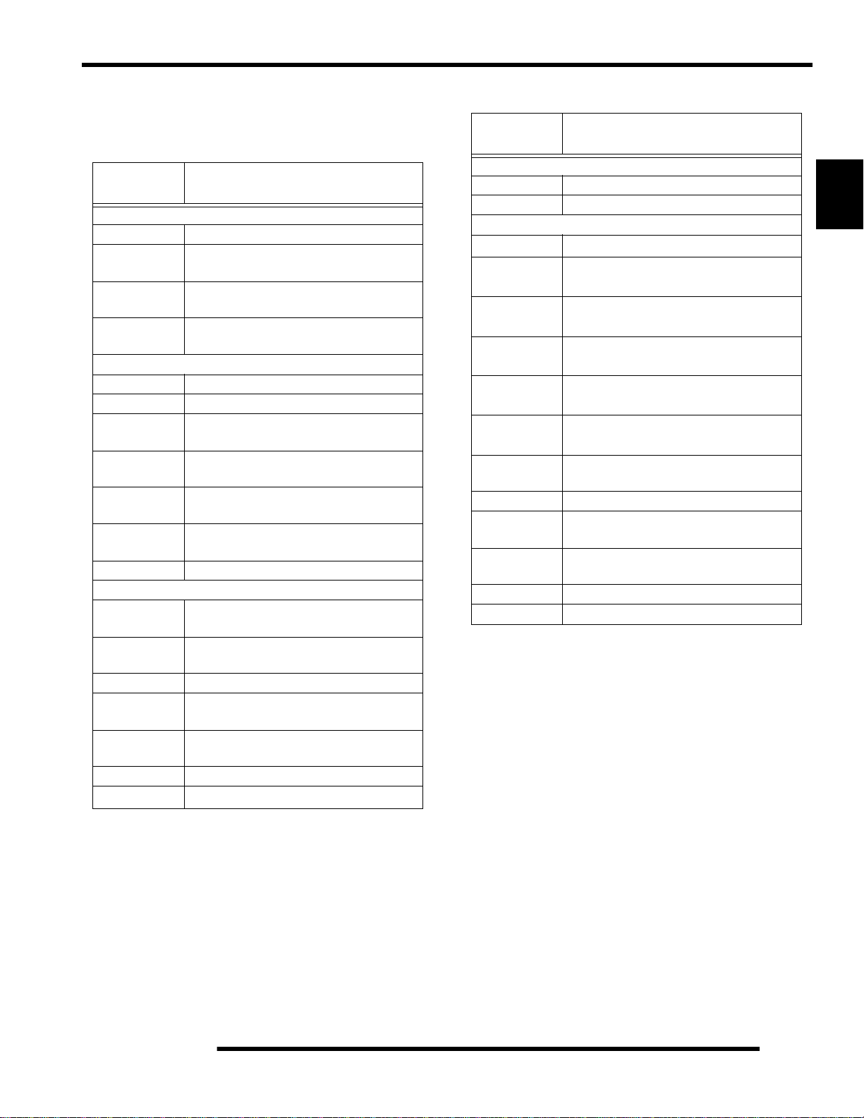
Polaris Lubricants, Maintenance and Service
Products
Table 2-2:
PART
NUMBER
Engine Lubricant
2870791 Fogging Oil (12 oz. Aerosol)
2871281
2871844
2871567
Gearcase / Transmission Lubricants
2876251 Demand Drive LT Premium Hub Fluid
3234438 Polaris ADC Hydraulic Fluid
2873602
2873603
2876160
2872276
2870465 Oil Pump for 1 Gallon Jug
2871322
2871423
2871460 Starter Drive Grease (12 count)
2871515
2871551
2871312 Grease Gun Kit
2871329
Engine Oil (Quart) Premium Synthetic
Engine Oil (Gallon) Premium Synthetic
Engine Oil (16 Gallon) Premium 4
Premium Synthetic AGL Gearcase Lube
Premium Synthetic AGL Gearcase Lube
Premium ATV Angle Drive Fluid
Premium ATV Angle Drive Fluid
Grease / Specialized Lubricants
DESCRIPTION
0W-40 (4-cycle) (12 count)
0W-40 (4-cycle) (4 count)
Synthetic 0W-40 (4-cycle)
(12 oz. bottle) (12 count)
(1 Gal. bottle) (4 count)
(32 oz.) (12 count)
(2.5 Gal.) (2 count)
Premium All Season Grease
(3 oz. cartridge) (24 count)
Premium All Season Grease
(14 oz. cartridge) (10 count)
Premium U-Joint Lube
(3 oz.) (24 Count)
Premium U-Joint Lube
(14 oz.) (10 count)
Dielectric Grease (Nyogel
Table 2-2:
PART
NUMBER
2871323 60/40 Coolant (Gallon) (6 count)
2871534 60/40 Coolant (Quart) (12 count )
Additives / Sealants / Thread Locking Agents / Misc.
2874275
2871956
2871950
2871951
2871953
2871557
2871326
2870652 Fuel Stabilizer (16 oz.) (12 count)
2871957
2871958
2870990 DOT 3 Brake Fluid (12 count)
2871557 Crankcase Sealant, 3 Bond 1215 (5 oz.)
DESCRIPTION
Coolant
Loctite
Primer N, Aerosol
Loctite
Thread Sealant 565
(50 ml.) (6 count)
Loctite
Threadlock 242
(6 ml.) (12 count)
Loctite
Threadlock 262
(50 ml.) (10 count)
Loctite
Threadlock 271
(6 ml.) (12 count)
3-Bond 1215
Premium Carbon Clean
(12 oz.) (12 count)
Black RTV Silicone Sealer
(3 oz. tube ) (12 count)
Black RTV Silicone Sealer
(11 oz. cartridge) (12 count)
Sealant
(5 oz.)
2
2.9
Page 30
MAINTENANCE
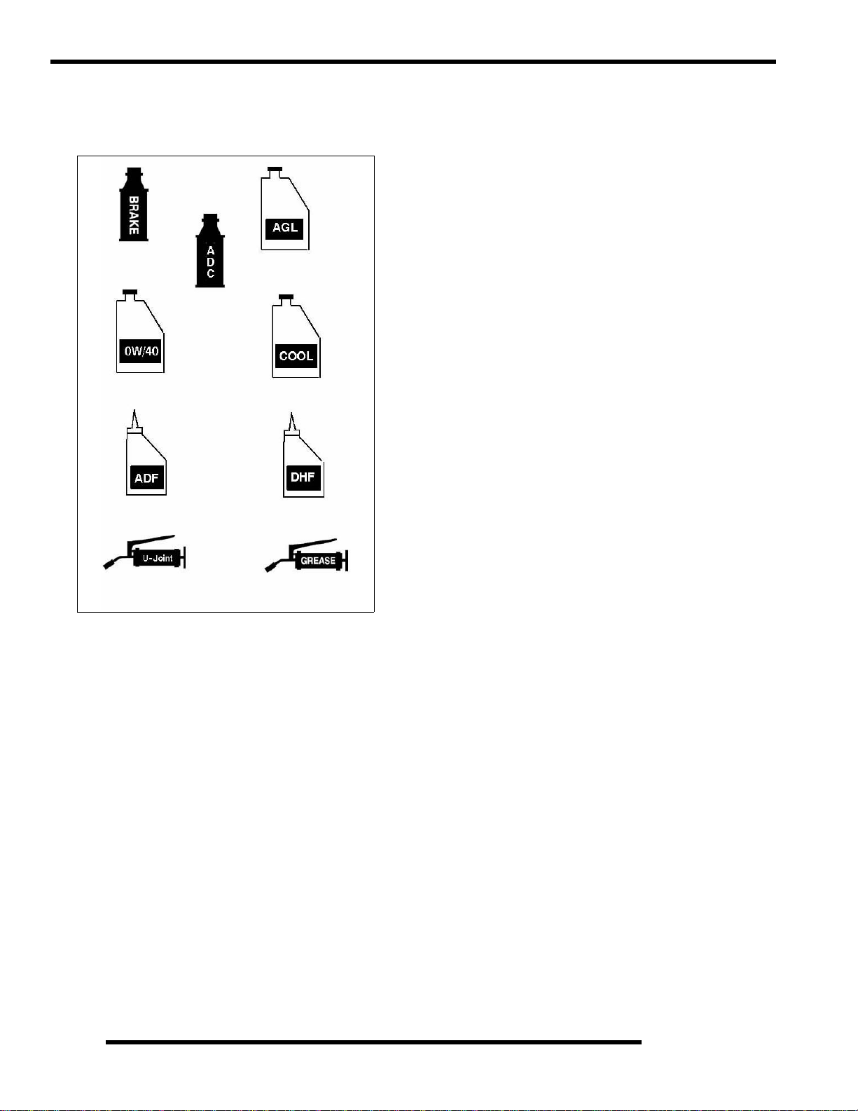
Polaris Lubricant Symbol Identification
NOTE: The symbols used are for quick reference in identifying
which lubricant/grease to use on each component.
Polaris DOT
Brake Fluid
Polaris ADC
Hydraulic Fluid
Polaris Synthetic
0W/40
Polaris Synthetic AGL
Gearcase Lube
Polaris 60/40
Coolant
Pre-Ride / Daily Inspection
Perform the following pre-ride inspection daily, and when
servicing the vehicle at each scheduled maintenance.
• Tires - check tire conditio n an d air pressures
• Fuel and oil - fill both to their proper level; Do not
overfill
• All brakes - check operation and adjustment (includes
auxiliary brake)
• Throttle -check for free operation
• Headlight/Taillight/Brakelight - check operation of all
indicator lights and switches
• Engine stop switch - check for proper function
• Wheels - check for loose wheel nuts and axle nuts;
check to be sure axle nuts are secured by cotter pins
• Air cleaner element - check for dirt or water; clean or
replace
• Steering - check for free operation, noting any unusual
looseness in any area
• Loose parts - visually inspect vehicle for any damaged
or loose nuts, bolts or fasteners
Polaris ATV Angle
Drive Fluid
Polaris U-Joint Lube
Demand Drive LT
Premium Hub Fluid
Polaris All
Season Grease
• Engine coolant - check for proper level at the recovery
bottle
• ADC Fluid Level - check for proper level
2.10
Page 31

Lubrication / Grease Points
1. Engine Oil
3. Front Gearcase
2. Transmission Fluid
5. Brake Fluid
8. Front Propshaft
MAINTENANCE
4. Rear Gearcase
2
6. Front A-Arm
7. Rear A-Arm
#I
1. Engine Oil Polaris 0W/40
2. Transmission
3A.
3B.
4. Rear Gearcase ATV Angle Drive Fluid
5. Brake Fluid Polaris Dot 3 Brake Fluid
6. Front A-Arm Polaris All Season Grease Locate fitting and grease.
7. Rear A-Arm Polaris All Season Grease Locate fitting and grease
5. Front Propshaft
* Perform more often under severe use, such as operation in water and under severe loads.
TEM LUBE METHOD
Check dipstick and add to
Front Gearcase
ADC Fluid
Polaris AGL Synthetic
Gearcase Lube
Demand Drive LT
Premium Hub Fluid
Polaris ADC Hydraulic
Polaris U-Joint Grease
Add lube to bottom fill hole.
Add specified quantity.
Drain completely . Add l ube to
specified quantity.
Fill master cylinder reservoir
Locate fitting and grease.
proper level.
Drain as directed.
to indicated level
FREQUENCY*
Change after 1st month, 6 months, or 100
hours thereafter; Change more often (25-50
hours) in extremely dirty conditions, or short
trip cold weather operation.
Change annually
Gearcase - Change annually
ADC - Change fluid every 2 years
Change annually
As required, change fluid every 2 years
Semi-annually
Semi-annually
Semi-annually
Semi-annually or 50 hours of operation 9refer to Maintenance Schedule for addition al information). More often under severe
conditions (operating in water or hauling heavy loads.
Annually or 100 hours of operation (refer to Maintenance Sched ule for additional information). More often under severe
conditions (operating in water or hauling heavy loads.
Grease conforming to NLGI No. 2, such as Polaris Premium All Season Grease, Conoco Superlube M, or Mobilgrease Special
2.11
Page 32

MAINTENANCE
Front Gearcase Lubrication
The front gearcase lubricant level should be checked and
changed in accordance with the maintenance schedule.
• Be sure vehicle is level before proceeding and in PARK
• Check vent hose to be sure it is routed properly and
unobstructed
• The correct front gearcase lubricant to use is Polaris
Premium Demand Hub Fluid.
FRONT GEARCASE
Fill Plug
8-10 ft.lbs.
(11-14 Nm)
Drain Plug
11 ft.lbs. (15 Nm)
To Change Gearcase Lubricant:
Drain Plug
1. Remove gearcase drain plug (A) located on the bottom of
the gearcase and drain oil. (The drain plug is accessible
through the skid plate.) Catch and discard used oil
properly.
2. Clean and reinstall drain plug (A) using a new sealing
washer (B). Torque to specification.
=
Specified Lubricant:
Demand Drive LT Premium Hub Fluid
CH Gearcase Capacity: 8.97 oz. (265 ml.)
ADC Gearcase Capacity: 9.3 oz. (275 ml.)
= T
Fill Plug Torque: 8-10 ft.lbs. (11-14 Nm)
Drain Plug Torque: 11 ft.lbs. (15 Nm)
To Check the Lubricant Level:
The front and rear gearcase lubricant level cannot be checked
with a dipstick. The gearcase must be drained and re-filled with
the proper amount of lubricant or be filled to the bottom of the
fill plug hole threads. Refer to procedures.
Fill Plug
Left Side View
3. Remove fill plug. Inspect the O-ring.
4. Fill with th e recommended fluid amount or to the bottom
of the fill plug hole threads. (See Illustration below).
Front Gearcase
Fill - Premium
Demand Drive
Hub Fluid
2.12
5. Install / torque fill plug and check for leaks.
Page 33

Transmission Lubrication
MAINTENANCE
The (transmission) lubricant level should be checked and
changed in accordance with the maintenance schedule.
• Be sure vehicle is level and in Park before proceeding.
• Check vent hose to be sure it is routed properly and
unobstructed.
• Follow instructions to check / change transmission
lubricant.
SPORTSMAN
=
Transmission - Specified Lubricant:
Polaris AGL Gearcase Lubricant
(Gallon - PN 2873603) (12 oz. - PN 2873602)
Sportsman - Capacity: 15 oz. (450 ml)
Sportsman X2 - Capacity: 32 oz. (948 ml)
= T
Transmission
Sportsman - Drain / Fill Plug Torque:
14 ft.lbs. (19 Nm)
Sportsman X2 - Drain / Fill Plug Torque:
20-25 ft.lbs. (27-34 Nm)
To Check the Fluid Level:
1. Remove fill plug from the back of the transmission and
visually inspect the oil level. Level is correct when it
reaches the bottom of the fill hole as shown at below.
NOTE: The drain and fill plug use a 5/16” hex for
removal and installation.
2
SPORTSMAN X2
Oil Fill Plug
Oil Fill LevelBottom Fill Plug
Hole Threads
To Change Lubricant:
1. Remove transmission drain plug t o drain the oil. Discard
used oil properly.
2. Clean and reinstall the drain plug. Torque to specification.
3. Remove fill plug.
4. Add the correct amount of Polaris AGL Gearcase
Lubricant.
5. Check for leaks.
6. Install fill plug. Torque to specification.
2.13
Page 34

MAINTENANCE
ADC Differential Hydraulic Circuit Fluid
Change
1. Make sure vehicle is parked on flat ground and allowed to
sit at least 30 minutes prior to bleeding hydraulic circuit.
2. Thoroughly clean area around and on remote reservoir and
bleeder valves.
3. Remove reservoir cap and diaphragm assembly.
4. Make sure hydraulic oil inside reservoir is free of debris.
If any debris is found, use clean rag or suction device to
remove from the reservoir.
NOTE: Debris in reservoir may block porting and
produce inadequate bleeding of the system.
Decreased performance may be encountered with
inadequate bleed of the hydraulic circuit.
5. Begin the bleeding process by filli ng reservoir to ‘MAX’
line with clean Polaris ADC hydraulic fluid. (AW ISO 10
hydraulic fluid equivalent).
6. Locate bleeder valves found on either side of differential
and remove the protective caps.
7. Turn bleeder valves counter-clockwise to loosen. Loosen
bleeder screw slowly, allowing oil and any trapped air to
flow out of fitting.
IMPORTANT: Do not allow hydraulic fluid in reservoir
to drain below minimum fill line. Close bleeder valve
before oil level falls below minimum fill line. Refilling
empty reservoir will result in air pockets becoming
trapped.
VEHICLE INSPECTION
Shift Link Rod Inspection
NOTE: Shift rod is preset at time of manufacturer.
1. Inspect shift link tie rod ends and replace if worn or
damaged. Lubricate pivot points with a light aerosol
lubricant or grease if desired.
Shift Mount
Shifter
Shift Link Rod
NOTE: If empty reservoir is encountered, filling of
fluid is still possible. Verify air is not trapped before
proceeding with step 7.
8. Continue steps 6 -8 on both sides in sequence until clean
fluid is seen when bleeding occurs.
9. Re-torque both bleeder valves to specification and reinstall
cover caps.
= T
Bleeder Valve Torque:
80 in. lbs. (9 Nm)
10. Fill reservoir with to a level midway between ‘MAX’ and
‘MIN’ fill lines. Verify no debris is found in reservoir oil.
11. Replace reservoir cap securely and wipe clean any residue.
2.14
Page 35

MAINTENANCE
Throttle Inspection
Check for smooth throttle opening and closing in all handlebar
positions. Throttle lever operation should be smooth and lever
must return freely without binding.
1. Place the gear selector in neutral.
2. Place shift selector in neutral and set parking brake.
3. Loosen lock nut on in-line cable adjuster (Ill. 1).
4. Turn handleb ars from full right to full left. If idle speed
increases at any point in the turning range, inspect throttle
cable routing and condition. Adjust cable tension as needed
until lock-to-lock turning can be accomplished with no rise
in engine rpm.
5. Replace the throttle cable if worn, kinked, or damaged.
To Remove ETC Cover:
1. Use a medium flat blade screwdriver and insert blade into
the pocket of the cover starting on the #1 position.
2. Twist screwdriver slightly while lifting on the cover to
release snap.
3. Repeat procedure at the other five locations as show n.
NOTE: Do not attempt to remove cover until all latch
points are released.
Throttle Cable / Electronic Throttle Control
(ETC Switch) Adjustment
1. Slide boot off throttle cable adjuster and jam nut.
2. Place shift selector in neutral and set parking brake.
3. Loosen lock nut on in-line cable adjuster (Ill. 1).
Boot
Adjuster Sleeve
4. Turn adjuster until specified freeplay is achieved at thumb
lever. (see illustration). After making adjustments, quickly
actuate the thumb lever several times and reverify freeplay.
Lock Nut
Boot
2
ETC Cover
Removal Sequence
Direction of Travel
1/16-1/8” Freeplay
= In. / mm.
Throttle Freeplay:
.0625 - .1250" (1.58 - 3.17mm)
5. Tighten lock nut securely and slide boot completely in
place to ensure a water-resistant seal.
6. Turn handlebars from left to right through the entire turning
range. If idle speed increases, check for proper cable
routing. If cable is routed properly and in good condition,
repeat adjustment procedure
2.15
Page 36

MAINTENANCE
Fuel System
WARNING
* Gasoline is extremely flammable and explosive
under certain conditions.
* EFI components are under high pressure. Verify
system pressure has been relieved before
disassembly.
* Never drain the fuel system when the engine is
hot. S e vere burn s may resul t
* Do not overfill the tank. The tank is at full capacity
when the fuel reaches the bottom of the filler neck.
Leave room for expansion of fuel.
* Never start the engine or let it run in an enclosed
area. Gasoline powered engine exhaust fumes are
poisonous and can cause loss of consciousness
and death in a short time.
* Do not smoke or allow open flames or sparks in
or near the area where refueling is performed or
where gasoline is stored.
* If you get gasoline in your eyes or if you should
swallow gasoline, seek medical attention
immediately.
* If you spill gasoline on your skin or clothing,
immediately wash with soap and water and change
clothing.
* Always stop the engine and refuel outdoors or in
a well ventilated area.Keep away from open flames
and electrical components when removing fuel
filter.
The fuel filter (1) should be replaced in accordance with the
Periodic Maintenance Chart. To replace the filter:
EFI Example
(1)
4. Remove fuel lines from filter, use shop towels to catch any
leaking fuel.
5. Install new filter in line with arrow pointed in direction of
fuel flow.
6. Install line locks on fuel lines and verify locks are seated.
7. Start engine and inspect for leaks.
Vent Lines
Check fuel tank, oil tank, battery and transmission vent lines for
signs of wear, deterioration, damage or leakage. Replace Be
sure vent lines are routed properly and secured with cable ties.
CAUTION
Verify vent lines are not kinked or damaged
Compression Test
NOTE: This engine does NOT have decompression
components. Compression readings will vary in
proportion to cranking speed during the test.
Average compression (measured) is about 150-200
psi during a compression test.
A smooth idle generally indicates good compression. Low
engine compression is rarely a factor in running condition
problems above idle speed. Abnormally high compression can
be caused by carbon deposits in the combustion chamber or
worn, damaged exhaust cam lobes. Inspect camshaft and
combustion chamber if compression is abnormally high.
A cylinder leakdown test is the best indication of engine
condition. Follow manufacturer's instructions to perform a
cylinder leakage test. (Never use high pressure leakage testers,
as crankshaft seals may dislodge and leak).
Cylinder Compression
Standard: 150-200 PSI
Cylinder Leakdown
Service Limit 15%
1. Disconnect negative battery cable.
2. Relieve the pressure on the fuel rail. (See Ch. 4)
3. Remove line locks at both ends of the filter.
2.16
(Inspect for cause if test exceeds 15%)
Page 37

MAINTENANCE
Engine Mounts
Inspect rubber engine mounts (A) for cracks or damage.
Check engine fasteners and mounts, ensure they are tight.
Spark Plug
5. Measure gap with a wire gauge. Refer to specifications for
proper spark plug type and gap. Adjust gap if necessary by
bending the side electrode carefully.
Spark Plug Gap
2
.036 (0.9 mm)
6. If necessary, replace spark plug with proper type.
CAUTION
Severe engine damage may occur if the incorrect
spark plug is used.
7. Apply a small amount of anti-seize compound to the spark
plug threads.
8. Install spark plug and to rque to specification.
1. Clean plug area so no dirt and debris can fall into engin e
when plug is removed. Remove spark plug high tension
lead.
2. Remove spark plug.
3. Inspect electrodes for wear and carbon buildup. Look for
a sharp outer edge with no rounding or erosion of the
electrodes.
4. Clean with electrical contact cleaner or a glass bead spark
plug cleaner only.
CAUTION
A wire brush or coated abrasive should not
be used for cleaning sparkplugs.
= T
Recommended Spark Plug
Refer to the Specifications page in
Chapter 1 for spark plug type.
Spark Plug Torque: 18 ft.lbs. (24 Nm)
Active Descent Control (ADC) Reservoir
Level
The Active Descent Control reservoir (DELUXE Models Only)
is located by the radiator fill cap. Check the level and verify it
is between the ‘MAX’ and ‘MIN’ lines. Add only Polaris ADC
fluid when required.
2.17
Page 38

MAINTENANCE
Battery Maintenance
Complete battery servicing information for both conventional
and sealed batteries can be found in Chapter 10 of this
manual.
WARNING
Battery electrolyte is poisonous. It contains sulfuric
acid. Serious burns can result from contact with
Internal: Drink large quantities of water or milk.
Eyes: Flush with water for 15 minutes and get
Batteries produce explosive gases. Keep sparks,
charging or using in an enclosed space. Always
NOTE: Expected battery shelf life is 6-8 months
depending on storage conditions. As a general rule
before placing the battery into service, check the
battery condition and charge accordingly.
NOTE: New Batteries: Batteries must be fully
charged before use or battery life will be reduced by
10-30% of full potential. Charge battery for 3-5 h ours
at a current equivalent of 1/10 of the battery's rated
amp/hour capacity. Do not use the alternator to
charge a new battery. (Refer to battery video PN
9917987).
(Conventional Battery Only)
When the electrolyte nears the lower level, remove the battery
and add distilled water only to the upper level line .
skin, eyes or clothing. Antidote:
External: Flush with water.
Follow with milk of magnesia, beaten egg, or
vegetable oil. Call physician immediately.
prompt medical attention.
flame, cigarettes, etc. away. Ventilate when
shield eyes when working near batteries.
KEEP OUT OF REACH OF CHILDREN.
Inspect the battery fluid level.
To Remove the Battery:
1. Disconnect holder strap and remove cover.
2. Disconnect battery negative (-) (black) cable first, followed
by the positive (+) (red) cable.
CAUTION
To reduce the chance of sparks: Whenever
removing the battery, disconnect the negative
(black) cable first. When reinstalling the battery,
install the negative cable last.
3. Disconnect the vent hose.
4. Remove the battery.
5. (Conventional Battery Only)
add distilled water only as needed to bring each cell to the
proper level. Do not overfill the battery.
IMPORTANT: Use only distilled water. Tap water
contains minerals which are harmful to a battery.
IMPORTANT: Do not allow cleaning solution or tap
water to enter a battery, as it will shorte n the life of the
battery.
6. Fully recharge the battery.
7. Reinstall battery caps (Conventional Battery Only)
8. Clean battery cables and terminals with a stiff wire brush.
Corrosion can be removed using a solution of one cup water
and one tablespoon baking soda. Rinse well with clean
water and dry thoroughly.
9. Reinstall battery, attaching positive (+) (red) cable first and
then the negative (-) (black) cable.
10. Reattach vent hose making sure it is properly routed and not
kinked or pinched.
11. Coat terminals and bolt threads with Dielectric Grease (PN
2871329).
12. Reinstall battery cover and holder strap.
Remove the filler caps and
.
Cooling System
Maintain between
upper and lower
level marks
2.18
The engine coolant level is controlled or maintained by the
recovery system. The recovery system components are the
recovery bottle, radiator filler neck, radiator pressure cap and
connecting hose.
As coolant operating temperature increases, the expanding
(heated) excess coolant is forced out of the radiator past the
pressure cap and into the recovery bottle. As engine coolant
temperature decreases the contracting (cooled) coolant is drawn
back up from the tank past the pressure cap and into the radiator.
• Some coolant level drop on new machines is normal as
the system is purging itself of trapped air. Observe
coolant levels often during the break-in period.
• Overheating of engine could occur if air is not fully
purged from system.
• Polaris Premium 60/40 anti-freeze is premixed and
ready to use. Do not dilute with water.
Page 39

MAINTENANCE
Coolant Strength / Type
Test the strength of the coolant using an antifreeze
hydrometer.
Antifreeze Hydrometer
• A 50/50 or 60/40 mixture of antifreeze and distilled
water will provide the optimum cooling, corrosion
protection, and antifreeze protection.
• Do not use tap water, straight antifreeze, or
straight water in the system. Tap water contains
minerals and impurities which build up in the
system.
• Straight water or antifreeze may cause the system
to freeze, corrode, or overheat.
Polaris 60/40 Anti-Freeze/ Coolant
(PN 2871323)
Radiator
1. Check radiator external air flow passages for restrictions or
damage.
2. Carefully straighten any bent radiator fins.
3. Remove any obstructions with compressed air or low
pressure water.
Cooling System Pressure Test
See Chapter 3 for pressure test procedures.
Reservoir Level Inspection
WARNING
Never remove the radiator pressure cap when the
engine is warm or hot. Escaping steam and fluid
can cause severe burns. The engine must be
allowed to cool before removing the pressure cap.
Remove any obstructions with compressed air or low pressure
water.
With the engine at operating temperature, the coolant level
should be between the upper and lower marks on the coolant
reservoir. If it is not:
2
Cooling Hoses
Inspect all hoses for cracks, deterioration, abrasion or leaks.
Replace if necessary.
Upper Radiator Hose
Lower Radiator Hose
1. Check tightness of all hose clamps.
2. Do not over-tighten hose clamps at radiator or radiator
fitting may distort, causing a restriction or leak.
Coolant Bottle
Fan
1. Remove reservoir cap. Verify the inner splash cap vent
hole is clear and open.
2. Fill reservoir to upper mark with Po laris Premium 60/40
Anti Freeze / Coolant (PN 2871323) or a mixture of
antifreeze and distilled water as required for freeze
protection in your area.
3. Reinstall cap.
NOTE: If overheating is evident, allow system to
cool completely and check coolant level in the
radiator. Inspect for signs of trapped air in system.
Recover Bottley
2.19
Page 40

MAINTENANCE
Radiator Coolant Level
WARNING
Never remove the radiator pressure cap when the
engine is warm or hot. Escaping steam and fluid
can cause severe burns. The engine must be
allowed to cool before removing the pressure cap.
NOTE: This procedure is only required if the cooling
system has been drained for maintenance and/or
repair. However, if the recovery bottle has run dry,
or if overheating is evident, the level in the radiator
should be inspected via the radiator cap first and
coolant added if necessary.
NOTE: Use of a non-standard pressure cap will not
allow the recovery system to function properly.
To Access the Radiator Pressure Cap:
Lift the front cargo cover . Remove access cover (A) by placing
your fingers under the front of the cover and pulling upward.
The radiator cap (B) is now accessible.
3. Remove clips (A ) from air box cover and remove cover.
Inspect the gasket. It should adhere tightly to the cover and
seal all the way around.
4. Loosen clamp and remove air filter assembly.
Cover
Seal
A
B
Air Filter Service
It is recommended that the air filter and pre filter be replaced
annually. When riding in extremely dusty conditions,
replacement is required more often.
The pre filter should be cleaned before each ride using the
following procedure:
1. Lift up on the rear of the seat.
2. Pull the seat back and free of the tabs.
NOTE: When reinstalling seat, make sure the slots
in the seat engage the tabs in the fuel tank.
Pre-filter
Main Element
Cleaning:
5. Slip the pre-filter element off of main element. Clean the
pre filter with hot soapy water.
6. Rinse and dry thoroughly.
7. Inspect element for tears or damage.
8. Inspect main filter and replace if necessary. If the filter has
been soaked with fuel or oil it must be replaced.
Installation:
9. Reinstall pre-filter element over main filter. Be sure the
element covers entire surface of main filter without folds,
creases, or gaps.
10. Reinstall filter on main filter mount. Place filter clamp over
the assembly and tighten.
2.20
Page 41

MAINTENANCE
NOTE: Apply a small amount of general purpose
grease to the sealing edges of the filter before
reinstalling.
A
Proper Filter
Placement
Filter Support
Air Box
Main Filter
NOTE: The sediment tube will require more frequent
service if the vehicle is opera ted in wet c ondit ion s or
at high throttle openings for extended periods.
2
B
A
Engine Breather
Four-cycle ATV engines are equipped with a engine breather
filter. The in-line filter is similar in appearance to a fuel filter.
The breather lines are located on top of the cylinder head cover,
below the gas tank. Be sure breather line is routed properly and
secured in place. Make sure the lines are not kinked or pinched.
In-line breather filters can be installed with the arrow pointing
in either direction.
Front of ATV
NOTE: The air filter should rest on the filter support.
Proper placement of the air filter is important to
prevent rattles and air leaks.
11. Install air box cover and secure with clips.
Air Box Sediment Tube
Periodically check the air box drain tube located toward the rear
of the machine. Drain whenever deposits are visible in the clear
tube.
1. Remove drain plug (A) from end of sediment tube (B).
2. Drain tube.
3. Reinstall drain plug.
To Cylinder
Head Cover
Breather
Hose
2.21
Page 42

MAINTENANCE
PVT Inspection / Drying Procedure
NOTE: If operating the ATV in or through water, be
sure to check the PVT cover and other components
for water ingestion. The ATV should be checked
immediately.
1. To release any water that maybe trapped in the PVT cover,
simply remove the PVT drain plug and O-ring (A) located
on the bottom of the PVT cover and let the water drain out.
The PVT drain plug is shown below.
A
Engine Oil Level
The twin engine is a wet-sump engine, meaning the oil is
contained in the bottom of the crankcase. To check the oil level:
Dipstick
1. Set machine on a level surface.
2. Be sure the machine has sat for awhile before removing the
dipstick. Do not run the engine and then check the oil level,
as this will result in an incorrect reading.
A
2. To further expel wat er from the cover and to dry out the
PVT system, shift the transmission to neutral and rev
engine slightly to expel the moisture and air-dry the belt and
clutches. Allow engine RPM to settle to idle speed, shift
transmission to lowest available range and test for belt
slippage. Operate ATV in lowest available range for a short
period of time until PVT system is dry.
Engine Ground
Inspect engine-to-frame ground cable connection. Be sure the
connection clean and tight.
3. Unlock the lever lock (A). Remove dipstick (B) and wipe
dry with a clean cloth.
A
B
2.22
Typical Ground Cable
Page 43

MAINTENANCE
4. Reinstall dipstick and push it into place. Do not lock the
dipstick.
NOTE: Make certain the dipstick is inserted all the
way into the filler tube to keep the angle and depth of
stick consistent. When reinstalling the dipstick,
make certain to seat the lever lock.
5. Remove dipstick and check to see that the oil level is in the
normal range. Add oil as indicated by the level on the
dipstick. Do not overfill. (See NOTE below!)
NOTE: Due to the dipstick entry angle into the
crankcase, the oil level will read higher on the
bottom side of the dipstick. Proper level indication
is determined on the upper side of the dipstick as it
is being removed, regardless of the level marks
being on top or on bottom. (See illustration)
Dipstick
Always read top side of dipstick to
properly check oil level in crankcase.
Oil/filter Change
1. Place vehicle on a level surface.
2. Run engine two to three minutes until warm. Stop engine.
3. Clean area around drain plug at bottom of engine.
4. Place a drain pan beneath crankcase and remove drain plug.
2
CAUTION
Do not allow hot oil to come into contact
with your skin, as serious burns may result.
5. Allow oil to drain completely.
6. Replace the sealing washer on drain plug.
NOTE: The sealing surfaces on drain plug and oil
tank should be clean and free of burrs, nicks or
scratches.
7. Reinstall drain plug and torque to specification.
= T
Drain Plug Torque:
15 ± 2 ft.lbs. (21.7 ± 2.7 Nm)
NOTE: A rising oil level between checks in cool
weather driving can indicate contaminants such as
gas or moisture collecting in the crankcase . If th e oil
level is over the full mark, change the oil
immediately.
8. Place shop towels beneath oil filter. Using Oil Filter
Wrench PV-43527, turn filter counterclockwise to remove.
Oil Filter
9. Using a clean dry cloth, clean filter sealing surface on
crankcase.
10. Lubricate O-ring on new filter with a film of fresh engine
oil. Check to make sure the O-ring is in good condition.
11. Install new filter and turn by hand until filter gasket contacts
the sealing surface, then turn an additional 1/2 turn.
12. Remove dipstick and fill sump with 2 quarts (1.9 l) of
Polaris Premium 4 Synthetic Oil.
13. Place gear selector in park and set the parking brake.
2.23
Page 44

MAINTENANCE
14. Start the engine and let it idle for one to two minutes. Stop
the engine and inspect for leaks.
15. Re-check the oil level on the dipstick and add oil as
necessary to bring the level to the upper mark on the
dipstick.
16. Dispose of used filter and oil properly.
Recommended Engine Oil:
Polaris Premium 0W/40 Synthetic
(PN 2871281)
Oil Filter Wrench: (PV-43527)
Oil Filter Torque: Turn by hand until filter
gasket contacts sealing surface, then turn an
additional 1/2 turn
Steering Inspection
WARNING
Due to the critical nature of the procedures outlined
in this chapter, Polaris recommends steering
component repair and adjustment be performed by
an authorized Polaris MSD-certified technician
when replacing worn or damaged steering par ts.
Use only genuine Polaris replacement parts.
Tie Rod / Steering
• To check for play in the tie rod end, grasp the steering
tie rod, pull in all directions feeling for movement.
• Repeat inspection for inner tie rod end on steering post.
• Replace any worn steering components. Steering
should move freely through entire range of travel
without binding.
• Elevate front end of machine so front wheels are off the
ground. Check for any looseness in front hub / wheel
assembly by grasping the tire firmly at top and bottom
first, and then at front and rear. Try to move the wheel
and hub by pushing inward and pulling outward.
• If abnormal movement is detected, inspect the hub and
wheel assembly to determine the cause ( possible loose
wheel nuts or loose front hub components).
The steering components should be checked periodically for
loose fasteners, worn tie rod ends, and damage. Also check to
make sure all cotter pins are in place. If cotter pins are removed,
they must not be re-used. Always use new cotter pins.
Replace any worn or damaged steering components. Steering
should move freely through entire range of travel without
binding. Check routing of all cables, hoses, and wiring t o be
sure the steering mechanism is not restricted or limited.
NOTE: Whenever steering components are
replaced, check front end alignment. Use only
genuine Polaris parts.
One of two methods can be used to measure toe alignment. The
string method and the chalk method. If adjustment is required,
refer to following pages for procedure.
2.24
Check for loose wheel or hub.
• Refer to the Body/Steering Chapter 5 or Final Drive
Chapter 7 for service procedures.
Camber/Caster
Camber and caster are non-adjustable.
Page 45

MAINTENANCE
Wheel Alignment
1. Place machine on a smooth level surface.
2. Set handlebars in a straight ahead position and secure
handlebars in this position.
3. Place a chalk mark on the center line of the front tires
approximately 10, (25.4 cm) from the floor or as close to
the hub/axle center line as possible.
NOTE: It is important that the height of both marks
be equally positioned in order to get an accurate
measurement.
4. Measure the distance between the marks and record the
measurement. Call this measurement “A”.
5. Rotate the tires 180
backward. Position chalk marks facing rearward, even with
the hub/axle centerline.
6. Again measure the distance between the marks and record.
Call this measurement “B”. Subtract measurement “B”
from measurement “A”. The difference between
measurements “A” and “B” is the vehicle toe alignment.
The recommended vehicle toe tolerance is 1/8, to 1/4, (.3
to .6 cm) toe out. This means the measurement at the front
of the tire (A) is 1/8, to 1/4, (.3 to .6 cm) wider than the
measurement at the rear (B).
by moving vehicle forward or
Toe Alignment
If toe alignment is incorrect, measure the distance between
vehicle center and each wheel. This will tell you which tie rod
needs adjusting.
NOTE: Be sure handlebars are straight ahead before
determining which tie rod(s) need adjustment.
CAUTION
During tie rod adjustment, it is very important that
the following precautions be taken when tightening
tie rod end jam nuts. If the rod end is positioned
incorrectly it will not pivot, and may break.
To Adjust Toe Alignment:
• Hold tie rod end to keep it from rotating.
• Loosen jam nuts at both end of the tie rod.
• Shorten or lengthen the tie rod until alignment is as
required to achieve the proper toe setting as specified
• IMPORTANT: When tightening the tie rod end jam
nuts, the rod ends must be held parallel to prevent rod
end damage and premature wear. Damage may not be
immediately apparent if done incorrectly. See
illustration above.
2
Chalk Line
Measurement “A”
Wheel Toe-Out:
(A) - (B) = 1/8 - 1/4" (.3 to .6 cm)
Measurement “B”
= In. / mm.
• After alignment is complete, torque jam nuts to
specification.
Hold Rod
End
Correctly
Tightened
Jam Nut
Incorrectly
Tightened Jam
Nut
= T
Tie Rod Jam Nut Torque:
12-14 ft. lbs. (16-19 Nm)
2.25
Page 46

MAINTENANCE
Exhaust Pipe
The exhaust pipe must be periodically purged of accumulated
carbon as follows:
1. Remove the clean out plugs locat ed on the bottom of the
muffler as shown
Clean Out Plug
2. Place the transmission in neutral and start the engine. Purge
accumulated carbon from the system by momentarily
revving the engine several times.
3. If some carbon is expelled, cover the exhaust outlet and rap
on the pipe around the clean out plugs while revving the
engine several more times.
6. Repeat Steps 2 through 5 until no more particles are
expelled when the engine is revved.
7. Stop the engine and allow the arrestor to cool.
8. Reinstall the clean out plugs.
WARNING
* Do not perform clean-out immediately after the
engine has been run, as the exhaust system
becomes very hot. Serious burns could result from
contact with hot exhaust components.
* To reduce fire hazard, make sure that there are no
combustible materials in the area when purging the
spark arrestor.
* Wear eye protection.
* Do not stand behind or in front of the vehicle while
purging the carbon from the spark arrestor.Never
run the engine in an enclosed area.
* Exhaust contains poisonous carbon monoxide
gas.
* Do not go under the machine while it is inclined.
Set the hand brake and block the wheels to prevent
roll back.
Failure to heed these warnings could result in
serious personal injury or death.
4. If particles are still suspected to be in the muffler, back the
machine onto an incline so the rear of the machine is one
foot higher than the front. Set the hand brake and block the
wheels. Make sure the machine is in neutral and repeat
Steps 2 and 3. See WARNING in this section.
5. If particles are still suspected to be in the muffler, drive the
machine onto the incline so the front of the machine is one
foot higher than the rear. Set the hand brake and block the
wheels. Make sure the machine is in neutral and repeat
Steps 2 and 3. SEE WARNING in this section.
1 ft. (30.5 cm)
Brake System Inspection
The following checks are recommended to keep the brake
system in good operating condition. Service life of brake system
components depends on operating conditions. Inspect brakes in
accordance with the maintenance schedule and before each ride.
• Keep fluid level in the master cylinder reservoir to the
indicated level inside reservoir (See Chapter 9)
• Use Polaris DOT-approved Brake Fluid.
• Check brake system for fluid leaks, look for dust build
up on lines and connections that may indicate a fluid
leak
• Check brake for excessive travel or spongy feel
• Check friction pads for wear, damage or looseness (see
Chapter 9)
• Check surface condition of the disc (see Chapter 9)
2.26
Page 47

MAINTENANCE
• Inspect thickness of brake pad friction material (see
Chapter 9)
Sight Glass
Parking Lock Brake
Brake Hose Inspection
Check brake system hoses and fittings for cracks, deterioration,
abrasion, and leaks. Tighten any loose fittings and replace any
worn or damaged parts.
2
Brake Pads
Pads should be changed when the friction material is worn
beyond the service limit.
Brake Pad
Measure Thickness
= In. / mm.
Brake Pad Service Limit:
.180" (4.6 mm)
Auxiliary (Rear) Brake Test
The auxiliary brake (A) should be checked for proper function.
A
1. Support the rear wheels off the ground.
2.27
Page 48

MAINTENANCE
2. While turning the rear wheels by hand, apply the auxiliary
foot brake. This brake should not stop the wheels from
turning until the lever is half way between its rest position
and bottoming on the footrest.
Auxiliary Foot Brake
Pedal - Full Height
Full Engagement
Floor Board Surface
Auxiliary Brake Adjustment
Use the following procedure to inspect the hydraulic auxiliary
(foot) brake system and adjust or bleed if necessary:
First, check foot brake effectiveness by applying 50 lb.
(approx.) downward force on the pedal. The top of the pedal
should be at least 1 inch, (25.4mm) above the surface of the
footrest.
Bleeding:
If free play is correct and brake pedal travel is still excessive, air
may be trapped somewhere in the system. Bleed the hydraulic
auxiliary brake system in a conventional manner, following the
procedure outlined in Brake Chapter 9.
Suspension: Spring Preload Adjustment
Operator weight and vehicle loading affect suspension spring
preload requirements. Adjust as necessary . Use Shock Spanner
Wrench (PN 2870872) to adjust the rear springs.
Front Suspension
• Compress and release front suspension. Dampening
should be smooth throughout the range of travel.
• Check all front suspension components for wear or
damage.
• Inspect front strut cartridges for leakage.
Rear Suspension
• Compress and release rear suspension. Dampening
should be smooth throughout the range of travel.
• Check all rear suspension components for wear or
damage.
• Inspect shock for leakage.
1/8 to 1/4 inch
Free Play
1 inch or greater
Floorboard
If less than one inch, two things must be examined:
Free Play:
= In. / mm.
Foot Brake Freeplay:
1/8 - 1/4 inch (3.2 - 6.35 mm)
CV Shaft Boot Inspection
Inspect the CV shaft boots in the front and rear of the ATV for
damage, tears, wear, or leaking grease. If the rubber boot
exhibits any of these symptoms, replace the boot. Refer to
Chapter 7 for CV boot replacement, or have your Polaris dealer
replace the boot.
INSPECT BOOTS
If free play is excessive, inspect pedal, linkage, and master
cylinder for wear or damage and replace any parts as needed.
2.28
Page 49

MAINTENANCE
ATV Controls
Check controls for proper operation, positioning and
adjustment.
Brake control and switch must be positioned to allow brake
lever to travel throughout entire range without contacting switch
body.
Wheel Inspection
Inspect all wheels for runout or damage. Check wheel nuts and
ensure they are tight. Do not over tighten the wheel nuts.
Item Specification
3. Elevate the side of the vehicle by placing a suitable stand
under the footrest frame.
4. Remove the wheel nuts and remove the wheel.
Wheel Installation
1. With the transmission in park and the parking brake
locked, place the wheel in the correct position on the wheel
hub. Be sure the valve stem is toward the outside and
rotation arrows on the tire point toward forward rotation.
2. Attach the wheel nuts and finger tighten them.
3. Lower the vehicle to th e ground.
4. Securely tighten the wheel nu ts to th e proper torq ue listed
in the table .
Steel Wheel
Aluminum Wheel
2
Steel - Front and Rear
Wheel Nuts
Aluminum - Front and Rear
Wheel Nuts
Front Hub Retaining Nut 70 ft.lbs. (90 Nm )
Rear Hub Retaining Nut 80 ft.lbs. (108 Nm)
27 ft.lbs. (37 Nm)
90 ft.lbs. (122 Nm)
Wheel Removal: Front Or Rear
4Wheel Nuts
Retaining Nut
CAUTION
Improperly installed wheels could affect vehic l e
handling and tire wear. On vehicles with tapered
rear wheel nuts, make sure tapered end of nut goes
into taper on wheel. Torque to proper specificatio n.
1. Stop the engine, place the transmission in gear and lock the
parking brake.
2. Loosen the wheel nuts slightly.
2.29
Page 50

MAINTENANCE
Tire Pressure
CAUTION
Maintain proper tire pressure. Refer to the warning
tire pressure decal applied to the vehicle.
Table 2-1:
TIRE PRESSURE INSPECTION (PSI - COLD)
Front Rear
55
Tire Inspection
• Improper tire inflation may affect ATV
maneuverability.
• When replacing a tire always use original equipment
size and type.
• The use of non-standard size or type tires may affect
ATV handlin g.
Front / Rear Storage Compartments
The front and rear storage (Sportsman Only) compartments are
easily accessible. T o open the fron t compartment turn t he latch
handle to the horizontal position on both sides. To close the
storage compartment turn the latch handles to the vertical
position.
Front Storage - Unlatched
Tire Tread Depth
Always replace tires when tread depth is worn to 1/8, (3 mm) or
less.
Tread Depth - 1/8” (3 mm)
WARNING
Operating an ATV with worn tires will increase the
possibility of the vehicle skidding and possible loss
of control.
Worn tires can cause an accident.
Always replace tires when the tread depth
measures 1/8inch (.3 cm) or less.
Frame, Nuts, Bolts, Fasteners
Front Storage - Latched
Sportsman Rear Storage -
Periodically inspect the torque of all fasteners in accordance
with the maintenance schedule. Check that all cotter pins are in
place. Refer to specific fastener torques listed in each chapter.
2.30
Page 51

MAINTENANCE
Winch Operation (If Equipped)
This information is for Sportsman models equipped with a
winch in the front.
The mini-rocker (IN/OUT) control controls the direction of the
cable for the winch. IN pulls the cable into the winch and OUT
feeds the cable out of the winch.
2
Winch Control
The winch control located on the side of the winch gives the
operator easy access to switch between ENGAGED and
FREESPOOL.
When the winch is ENGAGED, the winch only allows the cable
to be pulled IN or released OUT via the mini-rocker switch on
the handlebar.
Winch Handlebar Control
The winch is located in the front bumper area.
s
When the winch is FREESPOOL, the winch allows the cable to
be pulled out freely.
NOTE: The switch on the handlebar does not have to b e in
the OUT position.
L
FREESPOOL
ENGAGE
2.31
Page 52

MAINTENANCE
Winch Wire Locat ions
The winch wires can be located under the front cab area. Locate
the wires, remove the cap and hook up to winch the Blue and
Yellow (6 Ga.) wires to the winch. Refer to the installation
instructions for more details.
Winch Connector
Splash Guard for
Contactor mount
Winch Connecting
Harness
Locate the Red wire (6 Ga.) with the yellow crimp cover is
located in the rear fender area. The red wire connects to the
battery.
Winch Connecting Wire
The Orange/White wires are located under the front cover
(under headlight pod). The Orange/White wires supply the
control power to the winch.
2.32
Right Side Front Fender
Page 53

MAINTENANCE
Cleaning And Storage Of ATV
Cleaning the ATV
Keeping your AT V clean will not on ly improve its appearan ce
but it can also extend the life of various components. W ith a few
precautions, your A TV can be cleaned much like a n automobile.
Washing the ATV
The best and safest way to clean your A TV is with a garden hose
and a pail of mild soap and water. Use a professional type
washing mitten, cleaning the upper body first and the lower parts
last. Rinse with water frequently and dry with a chamois to
prevent water spots.
NOTE: If warning and safety labels are damaged, contact
your a Polaris dealer for free replacement.
Polaris does not recommend the use of a high pressure type car
wash system for washing the ATV . If a high pressure system is
used, exercise extreme care to avoid water damage to the wheel
bearings, transmission seals, body panels, brakes and warning
labels.
NOTE: Grease all zerk fittings immediately after
washing, and allow the vehicle to run for a while to
evaporate any water that may have entered the
engine or exhaust system.
Waxing the ATV
ATVs can be waxed with any non-ab rasive automotive paste
wax. A void the use of harsh cleaners since they can scratch the
body finish. Spray-on furniture polish is an acceptable
alternative. Do not use old cloths or pads which may contain dirt
particles that can scratch the finish. Polaris offers a detailing kit
for ATVs.
Clean the Exterior
Make necessary repairs and then clean the ATV thoroughly with
mild soap and warm water to remove all dirt and grime. Do n't
use harsh detergents or high pressur e washers. Some detergen ts
deteriorate rubber parts. Use dish soap type cleaners only. High
pressure washers may force water past seals.
Stabilize the Fuel
Fill the fuel tank. Add Polaris Carbon Clean Fuel Treatment or
Polaris Fuel Stabilizer . Follow the instructions on the container
for the recommended amount. (Carbon clean will also reduce
the possibility of bacterial growth in the fuel system.) Allow 1520 minutes of operation for the stabilizer to disperse through the
fuel in the tank and the fuel system.
Oil and Filter
Warm the engine and change the oil and filter. Follow the
procedure in this chapter for proper oil change.
Air Filter / Air Box
Inspect and clean or replace the pre-cleaner and air filter. Clean
the air box and drain the sediment tube.
Breather Filter
Inspect and clean or replace the breather filter.
Fluid Levels
Inspect the following fluid levels and change if necessary: front
gearcase; transmission; brake fluid (change every two years or
as required if fluid looks dark or contaminated).
Drain and Recoil Housing (If Applicable)
Remove the recoil housing drain plug and drain any moisture.
2
CAUTION
Certain products, including insect repellents and
chemicals, will damage plastic surfaces.
Use caution when using these
products near plastic surfaces.
Storage Tips
See the beginning of the chapter for Pure Polaris storage
products.
CAUTION
Starting the engine during the storage period
will disturb the protective film created
by fogging. Damage could occur.
Never start the engine during the storage period
Fog the Engine
Use Polaris Fogging Oil, following the instructions as directed.
If you choose not to use Polaris Fogging Oil, perform the
following procedure.
1. Treat the fuel system with Polaris Carbon Clean. If Polaris
fuel system additive is not used, the fuel tank and fuel lines
should be completely drained of gasoli n e .
2. To access the plug hole, use a section of clear 1/4" hose and
a small plastic squeeze bottle filled with the pre-measured
amount of oil.
3. Remove the spark plug(s). Rotate the pist on to BDC and
pour approximately two ounces of Polaris oil into the
cylinder.
NOTE: Do this carefully! If you miss the plug hole,
oil will drain from the spark plug cavity into the hole
at the front of the cylinder head and appear to be an
oil leak.
4. Apply dielectric grease to the inside of the spark plug cap
and install the cap onto the plug.
5. Turn the engine over several ti mes to ensure coverage of
piston rings, cylinder walls and crankshaft bearings.
2.33
Page 54

MAINTENANCE
6. After storage procedures are complete, do not start the
engine until unit is ready to be removed from storage.
Starting the engine will remove the protective coating from
the engine components.
Lubrication
Inspect all cables and lubricate with Polaris Cable Lubricant.
Follow lubrication guidelines in the maintenance section of the
service or owner's manual to completely grease and lubricate the
entire vehicle with Polaris Premium All Season Grease.
Battery Storage
Remove the battery from the vehicle and ensure that it's fully
charged before placing it in storage. See Chapter 10 for
instructions.
Engine Anti-Freeze
Test engine coolant strength and change if necessary. Coolant
should be replaced every two years.
Storage Ar ea / Covers
Set the tire pressure and safely support the A TV with the tires 12" off the ground. Be sure the storage area is well ventilated, and
cover the machine with a genuine Polaris ATV cover.
NOTE: Do not use plastic or coated materials. They
do not allow enough ventilation to prevent
condensation, and may promote corrosion and
oxidation.
Transporting the ATV
Follow these procedures when transporting the vehicle:
1. Turn off the engine and remove th e key to prevent loss
during transporting.
2. Always place the transmission in park and lock the parking
brake.
3. Be sure the fuel cap, oil cap and seat are installed correctly.
4. Always tie the frame of the A TV to the transporting unit
securely using suitable straps or rope.
2.34
Page 55

800 EFI Dual Exhaust Canister Maintenance
(Sportsman Only)
The canisters on select dual exhaust Polaris Sportsman 800 EFIs
(X2 not applicable) are silver ceramic coated. To maintain a
beautiful finish and prevent corrosion, periodic maintenance is
required.
CAUTION
DO NOT use caustic chemicals to clean, as they
may damage the finish.
1. Wash any accumulated mud or debris from the canisters
with a soft brush and soapy water.
2. Use a cleaner, such as HPC HiPerWash to clean away any
remaining grime, salts or oils.
3. If the canisters are stained from oils or other fluids, use fine
steel wool with HPC Liquid Buff
remove the stain.
4. After removing the stains, poli sh using Liquid Buff and
a soft cloth.
Cleaner and Polish to
MAINTENANCE
2
Repeat this procedure as often as desired to maintain the finish.
800 EFI Dual Exhaust System
(X2 not applicable)
2.35
Page 56

MAINTENANCE
Maintenance Schedule
Service Date Hours / Miles Service Performed Serviced By:
2.36
Page 57

ENGINE
CHAPTER 3
ENGINE
SPECIFICATIONS. . . . . . . . . . . . . . . . . . . . . . . . . . . . . . . . . . . . . . . . . . . . . . . . . . . . . . . 3.2
CRANKCASE EXPLODED VIEWS . . . . . . . . . . . . . . . . . . . . . . . . . . . . . . . . . . . . . . . . .3.2
ENGINE FASTENER TORQUE PATTERNS. . . . . . . . . . . . . . . . . . . . . . . . . . . . . . . . . .3.9
TORQUE SPECIFICATIONS . . . . . . . . . . . . . . . . . . . . . . . . . . . . . . . . . . . . . . . . . . . . .3.10
700/800 EFI ENGINE SERVICE SPECIFICATIONS . . . . . . . . . . . . . . . . . . . . . . . . . . .3.11
SPECIAL TOOLS . . . . . . . . . . . . . . . . . . . . . . . . . . . . . . . . . . . . . . . . . . . . . . . . . . . . . .3.13
GENERAL ENGINE SERVICE . . . . . . . . . . . . . . . . . . . . . . . . . . . . . . . . . . . . . . . . . . . . 3.14
ACCESSIBLE COMPONENTS. . . . . . . . . . . . . . . . . . . . . . . . . . . . . . . . . . . . . . . . . . . .3.14
PISTON IDENTIFICATION . . . . . . . . . . . . . . . . . . . . . . . . . . . . . . . . . . . . . . . . . . . . . . .3.14
COOLING SYSTEM SPECIFICATIONS. . . . . . . . . . . . . . . . . . . . . . . . . . . . . . . . . . . . .3.14
COOLING SYSTEM PRESSURE TEST. . . . . . . . . . . . . . . . . . . . . . . . . . . . . . . . . . . . .3.15
FOUR STROKE - COOLANT AIR BLEEDING PROCEDURE. . . . . . . . . . . . . . . . . . . .3.15
ENGINE REMOVAL (TYPICAL). . . . . . . . . . . . . . . . . . . . . . . . . . . . . . . . . . . . . . . . . . .3.16
ENGINE INSTALLATION NOTES . . . . . . . . . . . . . . . . . . . . . . . . . . . . . . . . . . . . . . . . .3.17
CYLINDER HONE SELECTION AND HONING PROCEDURE. . . . . . . . . . . . . . . . . . .3.18
HONING TO DEGLAZE . . . . . . . . . . . . . . . . . . . . . . . . . . . . . . . . . . . . . . . . . . . . . . . . .3.18
CLEANING THE CYLINDER AFTER HONING . . . . . . . . . . . . . . . . . . . . . . . . . . . . . . .3.18
OIL FLOW CHART. . . . . . . . . . . . . . . . . . . . . . . . . . . . . . . . . . . . . . . . . . . . . . . . . . . . .3.19
ENGINE LUBRICATION SPECIFICATIONS . . . . . . . . . . . . . . . . . . . . . . . . . . . . . . . . .3.19
OIL PRESSURE TEST. . . . . . . . . . . . . . . . . . . . . . . . . . . . . . . . . . . . . . . . . . . . . . . . . .3.19
ENGINE DISASSEMBLY AND INSPECTION. . . . . . . . . . . . . . . . . . . . . . . . . . . . . . . . . 3.20
CYLINDER HEAD ASSEMBLY EXPLODED VIEW . . . . . . . . . . . . . . . . . . . . . . . . . . . .3.20
ROCKER ARMS. . . . . . . . . . . . . . . . . . . . . . . . . . . . . . . . . . . . . . . . . . . . . . . . . . . . . . .3.21
PUSH RODS. . . . . . . . . . . . . . . . . . . . . . . . . . . . . . . . . . . . . . . . . . . . . . . . . . . . . . . . . .3.21
CYLINDER HEAD REMOVAL . . . . . . . . . . . . . . . . . . . . . . . . . . . . . . . . . . . . . . . . . . . .3.21
CYLINDER HEAD INSPECTION . . . . . . . . . . . . . . . . . . . . . . . . . . . . . . . . . . . . . . . . . .3.22
CYLINDER HEAD WARP. . . . . . . . . . . . . . . . . . . . . . . . . . . . . . . . . . . . . . . . . . . . . . . .3.22
VALVE SEAL/SPRING SERVICE
(ON ENGINE)3.22
CYLINDER HEAD DISASSEMBLY . . . . . . . . . . . . . . . . . . . . . . . . . . . . . . . . . . . . . . . .3.23
VALVE INSPECTION. . . . . . . . . . . . . . . . . . . . . . . . . . . . . . . . . . . . . . . . . . . . . . . . . . .3.24
COMBUSTION CHAMBER. . . . . . . . . . . . . . . . . . . . . . . . . . . . . . . . . . . . . . . . . . . . . . .3.25
VALVE SEAT RECONDITIONING . . . . . . . . . . . . . . . . . . . . . . . . . . . . . . . . . . . . . . . . .3.25
CYLINDER HEAD REASSEMBLY . . . . . . . . . . . . . . . . . . . . . . . . . . . . . . . . . . . . . . . . .3.27
VALVE SEALING TEST . . . . . . . . . . . . . . . . . . . . . . . . . . . . . . . . . . . . . . . . . . . . . . . . .3.28
CYLINDER REMOVAL. . . . . . . . . . . . . . . . . . . . . . . . . . . . . . . . . . . . . . . . . . . . . . . . . .3.28
VALVE LIFTER REMOVAL/INSPECTION. . . . . . . . . . . . . . . . . . . . . . . . . . . . . . . . . . .3.28
PISTON REMOVAL . . . . . . . . . . . . . . . . . . . . . . . . . . . . . . . . . . . . . . . . . . . . . . . . . . . .3.29
CYLINDER INSPECTION. . . . . . . . . . . . . . . . . . . . . . . . . . . . . . . . . . . . . . . . . . . . . . . .3.30
PISTON-TO-CYLINDER CLEARANCE . . . . . . . . . . . . . . . . . . . . . . . . . . . . . . . . . . . . .3.31
PISTON/ROD INSPECTION. . . . . . . . . . . . . . . . . . . . . . . . . . . . . . . . . . . . . . . . . . . . . .3.31
PISTON RING INSTALLED GAP. . . . . . . . . . . . . . . . . . . . . . . . . . . . . . . . . . . . . . . . . .3.32
STARTER DRIVE/BENDIX REMOVAL INSPECTION. . . . . . . . . . . . . . . . . . . . . . . . . .3.32
FLYWHEEL / STATOR REMOVAL / INSPECTION. . . . . . . . . . . . . . . . . . . . . . . . . . . .3.33
ENGINE CRANKCASE DISASSEMBLY / INSPECTION. . . . . . . . . . . . . . . . . . . . . . . .3.34
CAMSHAFT INSPECTION. . . . . . . . . . . . . . . . . . . . . . . . . . . . . . . . . . . . . . . . . . . . . . .3.41
ENGINE REASSEMBLY . . . . . . . . . . . . . . . . . . . . . . . . . . . . . . . . . . . . . . . . . . . . . . . . . 3.42
CRANKCASE REASSEMBLY . . . . . . . . . . . . . . . . . . . . . . . . . . . . . . . . . . . . . . . . . . . .3.42
FLYWHEEL / STATOR INSTALLATION . . . . . . . . . . . . . . . . . . . . . . . . . . . . . . . . . . . .3.53
CYLINDER HEAD REASSEMBLY . . . . . . . . . . . . . . . . . . . . . . . . . . . . . . . . . . . . . . . . .3.54
TROUBLESHOOTING. . . . . . . . . . . . . . . . . . . . . . . . . . . . . . . . . . . . . . . . . . . . . . . . . . . 3.56
ENGINE . . . . . . . . . . . . . . . . . . . . . . . . . . . . . . . . . . . . . . . . . . . . . . . . . . . . . . . . . . . . .3.56
COOLING SYSTEM . . . . . . . . . . . . . . . . . . . . . . . . . . . . . . . . . . . . . . . . . . . . . . . . . . . .3.57
800 EFI EXHAUST SYSTEM (DELUXE). . . . . . . . . . . . . . . . . . . . . . . . . . . . . . . . . . . . . 3.58
DUAL EXHAUST LAYOUT. . . . . . . . . . . . . . . . . . . . . . . . . . . . . . . . . . . . . . . . . . . . . . .3.58
3
3.1
Page 58

ENGINE
)
)
SPECIFICATIONS
Crankcase Exploded Views
A. J ourna lBear ings
B. Camshaft
C. Thrust Plate
D. Balance Shaft
E. Woodruff Key
F. Flange Seal
G. Crankshaft
H. Oil Pickup
I. Journal Bearings
J. Baffle
K. Oil Plug
L. Washer
M. O-ring
N. Crankcase
O. Crankcase Bolts
A
D
B
C
115 12 in.l
(13 1.35 Nm
F
60 6 in.lbs.
(6.8 .68 Nm)
N
G
M
H
E
60 6 in.l
(6.8 .68 Nm
I
I
NOTE: If needed, heat
the oil baffle bolts with a
heat gun to remove.
192 24 in.lbs
(21.7 2.7 Nm
K
L
J
3.2
O
22 2 ft.lbs. (30 3 Nm)
Apply Loctite242 to
bolt threads.
Apply White Lithium
Grease
Apply Moly
Lube Grease.
Page 59

Oil / Water Pump and Timing Cover Exploded View
A
B
C
D
E
J
K
L
22 2 ft.lbs. (30 3 Nm)
M
84 8 in.lbs. (9.5 .90 Nm)
A. Split Gear
B. Washer
C. Bolt
D. Oil Rotor
E. Oil Pump
F . Mag Gasket Cover
G . Impeller
H. Washer
I. Nut
J. Counterbalance Gear
K. Washer
L. Bolt
M. Oil Pump Bolts
N. Gear/Stator cover
O. Wire Hold down
P . Stator Housing Bolts
F
ENGINE
3
G
H
I
Oil Pump Bolt Tighten Sequence
No Grease on this
Portion of the Gasket!
Apply corrosion resistant
grease to stator grommet area.
N
O
P
96 3 in.lbs.
(10.85 0.35 Nm)
Mag Cover Bolt Tighten Sequence
Apply Polaris OW-40
oil to component
108 12 in.lbs.
(6.8 .68 Nm)
Apply White Lithium
Grease
3.3
Page 60

ENGINE
Starter / Flywheel / Water Pump Exploded View
Apply Polaris
Starter Grease
Apply Polaris 0W-40
oil to seal
Loctite Pipe Sealant
(PN 2871956)
A
84 8 ft.lbs. (9.5 0.9 Nm)
Tighten Top Bolt First
1
2
D
E
108 12 ft.lbs.
(12 1.35 Nm)
F
B
C
Water Pump Cover
Bolt Tighten Sequence
J
No Grease or Oil
O
N
K
L
96 12 in.lbs.
(10.85 1.35 Nm)
M
65 7 ft.lbs.
(88 9.5 Nm)
A. Bolts
B. Starter
C. Washer
D. Nut
E. Positive Cable
F. Negative Cable
G. Gasket
H. Clamp
I. Bolts
J. Gasket
K. Wa ter P ump C over
L. Bolts
M. Cr ank Nu t/Wash er
N. Flywheel
O. Bendix
G
H
96 12 in.lbs.
(10.85 1.35 Nm)
I
Stator Cover Bolt
Tighten Sequence
3.4
Page 61

Oil System / Level Assembly Exploded View
A. Clamp
B. Oil Fill Tube
C. Dipstick
D. O-ring
E. Hex Plug
F. Oil Filter Nipple
G. Oil Filter
H. Dowel
I. Galley Plug
J. Nut/washer
K. Spring
50 5 in.lbs. (5.64
0.56 Nm)
22 2 ft.lbs.
(30 3 Nm)
I
K
A
B
H
J
ENGINE
C
D
3
18 2 ft.lbs.
(24.4 2.71 Nm)
E
35 4 ft.lbs.
(47.5 5.4 Nm)
F
G
50 5 in. lbs.
(5.65 0.56 Nm)
3.5
Page 62

ENGINE
Cylinder / Cylinder Head Exploded View
Lubricate threads & between
washers and underside of bolt
heads with engine oil. Torque in
sequence provided.
Apply Moly Lube grease to valve
tips.
Gasket free of oil. Verify tabs
are visible.
Apply thin film of 0W-40
to 25-55 mm of cylinder bore.
Apply 0W-40 to piston pin or
pin bore.
Apply 0W-40 to lifters.
Do Not install expansion plug
more than 1.5 mm inward.
1.5 mm
1
(Apply each
Bolt Threads)
A
22 ± 2 ft.lbs.
(30 ± 3 Nm)
2
C
G
B
F
Initial: 35 4 ft. lbs (47.5 5.5
Nm) in sequence. Finalize
sequence by tightening an
additional 90 (1/4 turn)
Head Bolt Tighten
Sequence
3
D
E
Side View
A. Head Bolts
B. Rocker Arms
C. Head Assem bly
D. Gasket
E. Pushrods
F . Bushing
G. Expansion Plug
H. Cylinder
I. Piston Assembly
J. Circlip
K. Gasket
L. Hydraulic Lifter
Apply Polaris 0W--40 Oil
Apply Moly Lube Grease
4
5
3
4
H
I
Circlip UP
J
for Install
K
L
6
3.6
Page 63

Engine Sensors & Misc. Exploded View
ENGINE
A. Screws
B. Rocker Cover
C. Breather
D. O-ring Seal
E. Breather Bolts
F. Spark Plugs
G. Carburetor Boot
H. Bolts
I. Boot Clamp
J. Throttle Body
K. Crank Position Sensor
L. Thermistor
M. O-ring
N. Thermostat Housing
O. Bolts
P. Gasket
Q. Exhaust Manifold
R. Bolts
S. Thermostat
18 2 ft.lbs.
(24.5 2.7 Nm)
20 5 in.lbs.
(2.5 0.55 Nm)
Apply Corrosion
Resistant Grease
84 4 in.lbs.
(9.5 0.9 Nm)
20 5 in.lbs.
(2.5 0.55 Nm)
18 2 ft.lbs.
(24.5 2.7 Nm)
(Apply Dielectric Grease
to threads of Spark Plug)
G
H
I
E
A
B
C
D
3
F
J
K
84 4 in.lbs.
(9.5 0.9 Nm)
R
Q
P
18 2 ft.lbs.
(24.5 2.7 Nm)
25 3 ft.lbs.
(34 0.14 Nm)
L
M
NO
84 4 in.lbs.
(9.5 0.9 Nm)
3.7
Page 64

ENGINE
EFI Harness Exploded View
A. Fuel Injector
B. Fuel Rail
C. EFI Harness
B
18 2 ft.lbs.
(24.5 2.7 Nm)
C
A
3.8
NOTE: See Chapter 4 for more information on the EFI system.
Page 65

Engine Fastener Torque Patterns
Crankcase Bolt Tighten Sequence
ENGINE
3
22 2 ft.lbs. (30 3 Nm)
Lubricate threads and between washer and underside of bolt with engine oil.
Torque in sequence to spec provided, allow the gasket t o set for 1 minute, then
tighten in sequence 90
35 4 ft.lbs.
(47.5 5.5 Nm)
(1/4 turn).
+ 90
(1/4 turn)
3.9
Page 66

ENGINE
Torque Specifications
Table 3-1: Engine Torque Specifications
FASTENER SIZE IN.LBS. (NM) FT.LBS. (NM)
Camshaft Gear 8 mm 22 ± 2 (30 ± 3)
Camshaft Thrust Plate 6 mm 115 ± 12 (13 ± 1.35) 9.5 ± 1 (13 ± 1.35)
Carburetor Adaptor Bolts 8 mm 216 ± 24 (24.5-± 2.7) 18 ± 2 (24.5 ± 2.7)
Counterbalance Gear 8 mm 22 ± 2 (30 ± 3)
Crankcase Bolts 8 mm * 22 ± 2 (30 ± 3)
Crankcase Breather 5 mm 20 ± 5 (2.5 ± 0.55) Cylinder Head Bolts 11 mm * 35 ± 4 (47.5 ± 5.5)
Exhaust Manifold 8 mm 216 ± 24 (24.5 ± 2.70) 18 ± 2 (24.5 ± 2.7)
Flywheel 14 mm 65 ± 7 (88 ± 9.50)
Injector Rail 8 mm 216 ± 24 (24.5 ± 2.70) 18 ± 2 (24.5 ± 2.7 )
Magneto Cover 6 mm * 96 ± 3 (10.85 ± 0.35) Oil Baffle Weldment 5 mm 60 ± 6 (6.8 ± 0.6 8) Oil Drain Bolt (Crankcase) 12 mm 192 ± 24 (21.7 ± 2.7) 16 ± (21.7)
Oil Fill Tube Bolt 5 mm 50 ± 5 (5.64 ± 0.56) Oil Filter Pipe Fitting 20 mm 35 ± 4 (47.5 ± 5.4)
Oil Pick Up 5 mm 60 ± 6 (6.8 ± 0.68) Oil Pressure Relief Plug 10 mm 22 ± 2 (30 ± 3) Oil Pump Housing Screw 6 mm * 84 ± 8 (9.50 ± 0.90) Rocker Arm 8 mm * 22 ± 2 (30 ± 3)
Rocker Cover 6 mm * 84 ± 8 (9.5 ± 0.9) Spark Plug 14 mm 216 ± 24 (24.5 ± 2.7) 18 ± 2 (24.5 ± 2.7)
Starter Motor 6 mm * 84 ± 8 (9.5 ± 0.9) Stator Assembly 6 mm 96 ± 3 (10.85 ± 0.35) Stator Housing 6 mm * 96 ± 3 (10.85 ± 0.35) Temperature Switch 3/8 NPT 25 ± 3 (34 ± 4)
Thermostat Housing 6 mm 84 ± 8 (9.5 ± 0.9) Timing Plug 3/4-16 7-9 (10-12 Nm)
Trigger Coil/Stator Wire Holddown 5 mm * 96 ± 3 (10.85 ± 0.35) Water Pump Housing Cover 6 mm * 96 ± 3 (10.85 ± 0.35) Water Pump Impeller Nut 8 mm 108 ± 3 (12 ± 0.35) -
NOTE: * See exploded views for notes or torque sequences.
3.10
Page 67

700/800 EFI Engine Service Specifications
Table 3-1: Engine Specifications
MAIN COMPONENT: CYLINDER HEAD EH068OLE / EH076OLE
Cam Lobe Height - Intake / Exhaust 1.3334" (33.8674 mm)
Camshaft Journal Outer Diameter - Mag 1.654" 0.00039" (42 0.010 mm)
Camshaft Journal Outer Diameter - Center 1.634" 0.00039" (41.50 0.010 mm)
ENGINE
Camshaft Journal Outer Diameter - PTO 1.614" 0.00039" (41 0.010 mm)
Camshaft
Counter Balance C ounter Balance End Play 0.005" (0.127 mm)
Cylinder Head
Valve Seat
Valve Guide
Camshaft Journal Bore Inner Diameter - Mag 1.656" 0.00039" (42.07 0.010 mm)
Camshaft Journal Bore Inner Diameter - Center 1.637" 0.00039" (41.58 0.010 mm)
Camshaft Journal Bore Inner Diameter - PTO 1.617" 0.00039" (41.07 0.010 mm)
Camshaft Oil Clearance 0.00276" 0.00079" (0.07 0.02 mm)
Camshaft End Play 0.0167" 0.0098" (0.425 0.25 mm)
Cylinder Head - Surface warp limit 0.00394" (0.1 mm)
Cylinder Head - Standard height 3.478" (88.35 mm)
Valve Seat - Contacting Width - Intake
Valve Seat - Contacting Width - Exhaust
Valve Seat Angle 45.5 0.255
Valve Guide Inner diameter 0.2367" 0.00029" (6.012 0.007 mm)
Valve Guide Protrusion Above Head 0.807" 0.0039" (20.50 0.01 mm)
0.0472" 0.00787" - 0.0039"
(1.20 0.20 - 0.10mm)
0.0591" 0.00787" - 0.0039"
(1.50 0.20 - 0.10 mm)
3
Valve
Valve Spring
Valve Margin Thickness - Intake
Valve Margin Thickness - Exhaust
Valve Stem Diameter - Intake 0.2356" 0.00039" (5.985 0.01 mm)
Valve Stem Diameter - Exhaust 0.2351" 0.00039" (5.972 0.01 mm)
Valve Stem Oil Clearance - Intake 0.00228" 0.00098" (0.058
Valve Stem Oil Clearance - Exhaust 0.00275" 0.00098" (0.0870 0.025mm)
Valve Stem Overall Length - Intake 4.51" 0.01476" (114.5550 0.375 mm)
Valve Stem Overall Length - Exhaust 4.5453" .01496" (115.45 0.38 mm)
Valve Spring Overall Length - Free Length 1.735" (46.069 mm)
Valve Spring Overall Length - Installed Height
Standard: 0.79" (20.06 mm)
Max- 0.98" (24.89 mm) Min- 0.59" (14.98 mm)
Standard: 0.80" (20.32 mm)
Max- 1.0" (25.4 mm) Min- 0.60" (15.24 mm)
0.025 mm)
Intake - 1.4638" (37.18 mm)
Exhaust - 1.4736" (37.43 mm)
3.11
Page 68

ENGINE
Table 3-2: Engine Specifications
MAIN COMPONENTS: CYLINDER/PISTON/
C
ONNECTING ROD
Cylinder - Surface warp limit
(mating with cylinder head)
Cylinder Bore - Standard 3.1495" (80 mm) 3.1495" (80 mm)
Cylinder
Lifter
Piston
Piston Pin
Cylinder Taper Limit 0.00031" (0.008 mm) 0.00031" (0.008 mm)
Cylinder Out of Round Limit 0.00030" (0.0075 mm) 0.00030" (0.0075 mm )
Cylinder to Piston Clearance
Lifter Outer Diameter
Standard
Lifter Block Bore
Piston - Standard
Piston Standard Inner
Diameter of Piston Pin Bore
Piston Pin Outer Diameter
Piston Pin - Standard
Clearance - Piston Pin to Pin
Piston Pin - Degree of Fit
EH068OLE EH076OLE
0.004" (0.10 mm) 0.004" (0.10 mm)
.0015" .00059"
(.040 .015mm)
0.84245" 0.00025"
(21.39 8 0.00635 mm)
0.8438" 0.00062"
(21.4322 0.0157 mm)
3.1477" .000121"
(79.954 .003mm)
0.78789" .00009"
(20.0125 0.003 mm)
0.7874" - 0.7872"
(20 - 19.995 mm)
0.00059" 0.0002"
(0.015 0.005 mm)
Piston pin must be a push fit
(by hand) at 68 F (20 C)
.0015" .00059"
(.040 .015mm)
0.84245" 0.00025"
(21.39 8 0.00635 mm)
0.8438" 0.00062"
(21.4322 0.0157 mm)
3.14803" + .00028"
(79.960 + .007 mm)
0.70902" .00012"
(18.009 0.003 mm)
0.70866" - 0.70846"
(18 - 17.995 mm)
0.00047" 0.00024"
(0.012 0.006 mm)
Piston pin must be a push fit
(by hand) at 68 F (20 C)
3.12
Page 69

ENGINE
Table 3-3: Engine Specifications
MAIN COMPONENTS: PISTON/ CONNECTING ROD EH068OLE EH076OLE
T op Ring - Standard
Top Ring - Limit > 15% Leakdown > 15% Leakdown
Installed
Gap
Piston Ring
Ring to
Groove
Clearance
Connecting
Rod
Crankshaft Crankshaft Runout Limit 0.00236" (0.060mm) Same
Second Ring - Standard
Second Ring - Limit > 15% Leakdown > 15% Leakdown
Oil Ring - Standard
Oil Ring - Limit > 15% Leakdown > 15% Leakdown
T op Ring - Standard
Top Ring - Limit > 15% Leakdown > 15% Leakdown
Second Ring - Standard
Second Ring - Limit > 15% Leakdown > 15% Leakdown
Connecting Rod Small End I.D.
Connecting Rod Small End
Radial Clearance
Connecting Rod Big End
Side Clearance
Connecting Rod Big End
Radial Clearance
0.0059 0.138"
(0.15 0.35mm)
0.0098 0.197"
(0.25 0.50mm)
0.0196 0.00984"
(0.50 0.25mm)
0.0024" 0.0008"
(0.060 0.020 mm)
0.0028" 0.0008"
(0.070 0.020 mm)
0.789" 0.78841"
(20.030 20.015 mm)
0.0098" 0.00039"
(0.025 0.010mm)
0.01181" 0.00591"
(0.030 0.015mm)
0.0015" 0.00006"
(0.0038 0.0015mm)
0.0059 0.138"
(0.15 0.35mm)
0.0098 0.197"
(0.25 0.50mm)
0.0196 0.00984"
(0.50 0.25mm)
0.0024" 0.0008"
(0.060 0.020 mm)
0.0028" 0.0008"
(0.070 0.020 mm)
0.7096" 0.70846"
(18 17.995 mm)
Same
Same
Same
3
Special Tools
PART NUMBER TOOL DESCRIPTION
PV-43527 OIL FILTER WRENCH
2200634 VALVE SEAT RECONDITIONING KIT
PU-45257 VALVE SPRING COMPRESSOR
PU-45652 VALVE PRESSURE HOSE
2871043 FLYWHEEL PULLER
2870390 PISTON SUPPORT BLOCK
PU-45497-1 CAM GEAR SPRING INSTALLATION KIT
PU-45497-2 CAM GEAR TOOTH ALIGNMENT TOOL
PU-45498 CAM SPANNER WRENCH
PU-45838 GEAR HOLDER
PA-44995 WATER PUMP MECHANICAL SEAL INSTALLER
PU-45543 UNIVERSAL DRIVER HANDLE
PA-45483 MAIN SEAL INSTALLER
PU-45658 CRANKSHAFT MAIN SEAL SAVER
PA-45401 WATER PUMP SEAL SAVER
2870975 MITY VAC
PU-45778 OIL SYSTEM PRIMING TOOL
PRESSURE TEST TOOL
3.13
Page 70

ENGINE
GENERAL ENGINE SERVICE
Accessible Components
Following Components can be serviced or removed with the
engine installed:
• Flywheel
• Alternator (Stator)
• Starter Motor/Drive
• Cylinder Head
• Cylinder
• Piston/Rings
• Camshaft
• Rocker Arms
• Oil pump/Water Pump/Oil Pump Drive Gear
• Gear Train Components
Following Components Require Engine Removal for service:
• Counterbalance Shaft or Bearings
• Connecting Rod
•Crankshaft
Cooling System Specifications
Table 3-2:
APPROX.
CONDITION
Hot light ON 178 - 190
Fan Off 296 - 316
Fan On 236 - 251
System
Capacity
Radiator Cap
Pressure Relief
Recommended Coolant
Use only high quality antifreeze/coolant mixed with distilled
water in a 50/50 or 60/40 ratio, depending on freeze protection
required in your area. CAUTION: Using tap water in the
cooling system will lead to a buildup of deposits which may
restrict coolant flow and reduce heat dissipation, resulting in
possible engine damage. Polaris Premium 60/40 Antifreeze/
Coolant is recommended for use in all cooling systems and
comes pre-mixed, ready to use.
R
EADING (MIN.-
M
AX)
Refer To Chapter 1 Specifications
T
215
180
195
13 PSI
EMPERATURE
F (108 C)
F (82 C)
F (91 C)
• Crankshaft Main Bearings
• Crankcase
Piston Identification
Four stroke engine rings have a rectangular profile. See
“PISTON RING INST ALLED GAP” for ring installation. Use
the information below to identify pistons and rings.
Table 3-1:
ENGINE MODEL PISTON DIAMETER
EH068OLE
EH076OLE
80 mm
Thermostat
Cylinder Head
Radiator
Water Pump
Cylinder
3.14
Page 71

ENGINE
Cooling System Pressure Test
WARNING
Never remove radiator cap when engine is warm or
hot. The cooling system is under pressure and
serious burns may result. Allow the engine and
cooling system to cool before servicing.
1. Remove front cover.
2. Remove recovery bottle hose from cool ant filler neck.
3. Connect a Mity Vac
nipple and pressurize system to 10 psi. The system m ust
retain 10 psi for five minutes or longer. If pressure loss is
evident within five minutes, check the radiator, hoses,
clamps and water pump seals for leakage.
(PN 2870975) to the filler neck
Radiator Cap Pressure Test
1. Remove radiator cap and test cap using a commercially
available cap tester.
2. The radiator cap relief pressure is 13 psi. Replace cap if it
does not meet this specification.
Upper Engine Hose
Four Stroke - Coolant Air Bleeding
Procedure
Pump Hose By
Hand to Help
Purge System
Squeeze Hose
Here to Help
Purge Air From
System
3
Polaris Premium
Antifreeze
2871534 - Quart
2871323 - Gallon
Use this procedure when a unit overheats and no apparent leaks
in the cooling system are found.
NOTE: If the coolant level is LOW in the radi ator, or if there
are leaks in the system, the coolant system will not draw
coolant from the reservoir tank.
Fan Assembly
Hose
Lower Engine Hose Radiator
Surge Tank
1. Park machine on a flat surface. Remove radiator cap and
top off coolant. Leave the cap off of the radiator. Start and
idle machine for 5-10 minutes until steam is visible in the
radiator cap area.
2. Stop the engine and let cool for a few m inutes or until an
air bubble is seen at the filler neck, or there is a dropping
of the coolant level indicating that coolant has been pulled
into the system.
NOTE: Slowly squeezing the hose after the bend
below the filler neck will aid in purging the system of
air. Pump the hose using your hand several times as
shown in the diagram. Elevating the rear of the ATV
with a floor jack (rear tires 4-6, off the ground) also
aids the purging of air from the system.
3. Always add coolant to the radiator first, filling to the top of
the neck to replace air that has been purged from the system.
Fill the reservoir only after you have completely filled the
cooling system at the radiator filler neck.
4. Repeat Steps 1 and 2 four o r five times or until no more
coolant is pulled into the system.
5. In some instances, Steps 1 and 2 may have to be performed
with the radiator cap on to prevent coolant loss.
6. To test, install the radiator cap and idle machine until fan
comes on. Make sure the fan comes on before the hot light.
3.15
Page 72
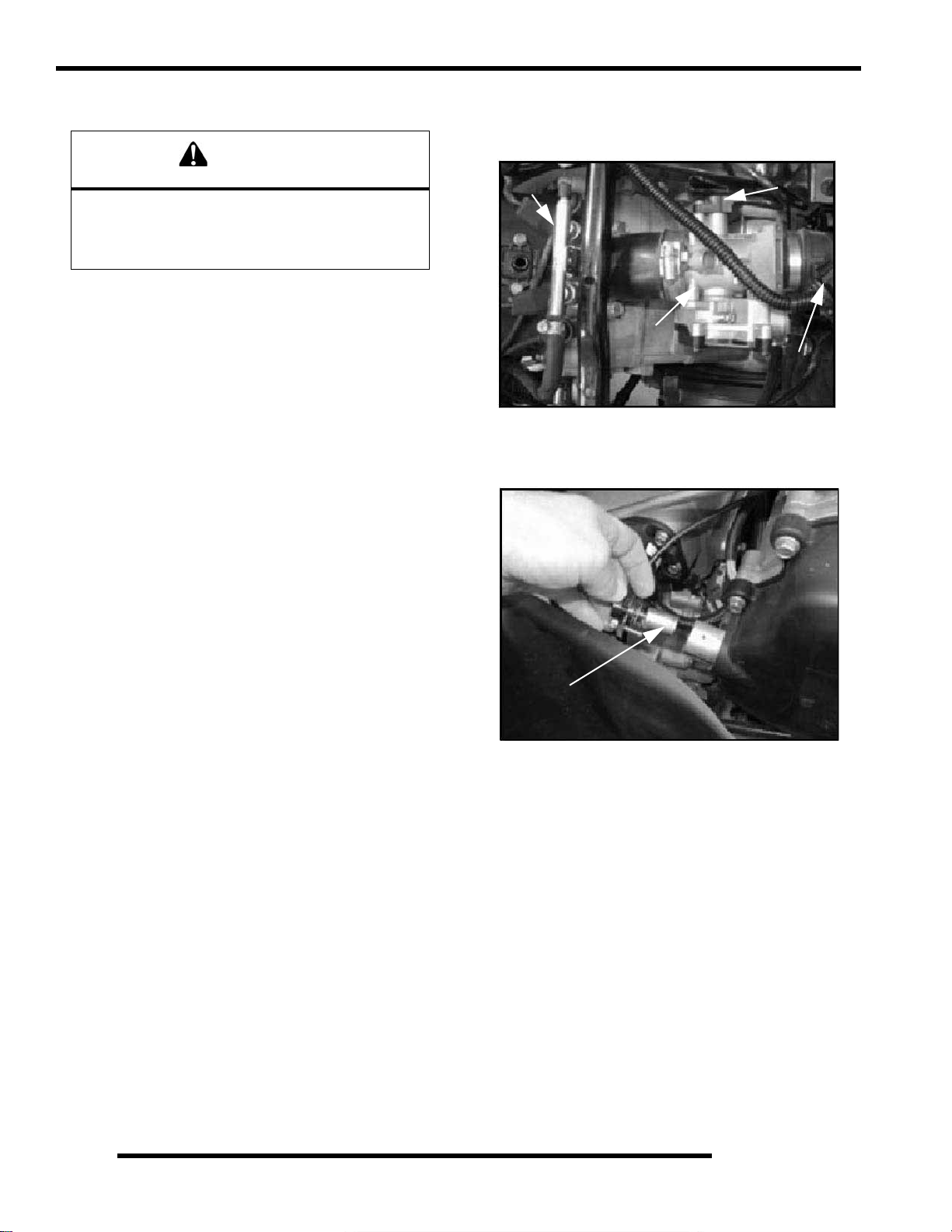
ENGINE
Engine Removal (Typical)
WARNING
Always wear safety glasses and proper shop
clothing when performing the procedures in this
manual. Failing to do so may lead to possible inju ry
or death.
1. Clean work area.
2. Thoroughly clean ATV engine and chassis.
3. Disconnect battery (-) negative cable.
4. Remove the following parts as required:
• Seat
• Left and right side covers (refer to Chapter 5)
• Fuel tank covers
• Fuel tank (refer to Chapter 4)
• Springs from exhaust pipe and remove pipe.
5. Drain coolant and engine oil.
6. Remove air pre-cleaner and du ct.
7. Remove airbox.
8. Disconnect the throttle body sensor (C) and T-BAP sensor
(D). Remove throttle body (A). Insert a shop towel into
the engine intake to prevent dirt from entering the ports.
9. Relieve the fuel pressure in the fuel rail (refer to Chapter 4,
FUEL INJECTION") for proper procedure. Carefully
remove the fuel rail (B) and injectors.
B
C
A
D
10. Disconnect spark plug high tension leads.
11. R emove the crank position sensor (E) located on the mag
cover.
E
12. Remove the air breather line .
13. Disconnect the coolant hoses. Properly dispose of any
antifreeze from the engine or hoses.
3.16
Page 73

ENGINE
14. Refer to PVT System Chapter 6 to remove outer clutch
cover, drive belt, drive clutch, driven clutch, and inner
cover (F).
F
15. When removing starter cables, note and mark ground cable
and positive (+) cable mounting angle and locations.
Remove cables.
16. Remove transmission linkage rod from gear selector and
secure out of the way.
17. Disconnect coolant temperature sensor wire located on the
cylinder.
18. Remove engine to chassis ground cable.
19. Remove all engine mount nuts and / or engine mount plates.
Remove the frame brace (G) from the front left side of the
frame.
G
3
20. Remove the engine from the left side of the frame.
NOTE: Use caution when lifting the engine out of
frame. Use an engine lift or other means if the
engine is too heavy to be lifted manually.
21. For engine installation, reverse procedures.
3.17
Page 74

ENGINE
Engine Installation Notes
After the engine is installed in the frame, review this checklist
and perform all steps that apply:
General Items
1. Install previously removed components using new gaskets,
seals, and fasteners where applicable.
2. Perform regular checks on fluid levels, controls, and all
important areas on the vehicle as outlined in the daily preride inspection checklist (refer to Chapter 2 or the Owner's
Manual).
PVT System
1. Adjust center distance of drive and driven clutch. (Chapter
6)
2. Adjust clutch offset, alignment, and belt deflection.
(Chapter 6)
3. Clean clutch sheaves thoroughly and inspect inlet and
outlet ducts for proper routing and sealing. (Chapter 6)
Transmission
1. Inspect transmission operation and adjust linkage if
necessary. Refer to Chapter 2 and Chapter 8.
Exhaust
1. Replace exhaust gaskets. Seal connections with high temp
silicone sealant.
2. Check to be sure all springs are in good condi tion.
Bleed Cooling System
NOTE: This cooling system contains vent lines to
help purge trapped air during filling. Bleeding
generally should not be necessary.
1. Remove radiator cap and slowly add coolant to the bottom
of filler neck.
2. Fill coolant reservoir tank to full mark.
3. Install radiator cap and gently squeeze coolant hoses to
force any trapped air out of system.
4. Again, remove radiator cap and slow ly add coolant to the
bottom of fill neck if needed.
5. Start engine and observe coolant level in the radiator.
Allow air to purge and top off as necessary. Reinstall
radiator cap and bring engine to operating temperature.
After engine is cool, check level in reservoir tank and add
coolant if necessary.
NOTE: Should the reservoir tank become empty, it
will be necessary to refill at the radiator and repeat
the bleeding procedure.
Engine Break-In Period
The break-in period for a Polaris ATV engine is defined as the
first ten hours of operation, or the time it takes to use two full
tanks of gasoline. No single action on your part is as important
as a proper break-in period. Careful treatment of a new engine
will result in more efficient performance and longer life for the
engine. Perform the following procedures carefully.
CAUTION
Use only Polaris Premium 0-40W All Season
synthetic oil or equivalent.
Never substitute or mix oil brands. Serious engine
d a m a g e a n d v o i d i n g o f w a r r a n t y c a n r e s u l t .
Do not operate at full throttle or high speed s fo r
extended periods during the first three hours of use.
Excessive heat can build up and cause damage to
close fitted engine parts.
1. Fill fuel tank with unleaded or leaded fuel which has a
minimum pump octane number of 87= (R+ M)/2.
2. Check oil reservoir level i ndicated on dip stick. Add o il if
necessary (Refer to Chapter 2, “Engine Oil Level” ).
3. Drive slowly at first to gradually bring engine up to
operating temperature.
4. Vary throttle positions. Do not operate at sustained idle or
sustained high speed.
5. Perform regular checks on fluid levels, controls and all
important bolt torques. Pull only light loads duri ng initial
break in.
6. Pull only light loads during initial break-in.
7. Change break in oil and filter at 20 hours or 200 miles.
Cylinder Hone Selection And Honing
Procedure
CAUTION
A hone which will straighten as well as remove
material from the cylinder is very important. Using a
common spring loaded glaze breaker for honing is
not advised for nicasil cylinders.
Polaris recommends using a rigid hone or arbo r
honing machine. Cylinders may be wet or dry
honed depending upon the hone manufacturer's
recommendations.
Wet honing removes more material faster and
leaves a more distinct pattern in the bore.
Cylinders may be wet or dry honed depending upon the hone
manufacturer’s recommendations. Wet honing removes more
material faster and leaves a more distinct pattern in the bore.
3.18
Page 75

Honing To Deglaze
A finished cylinder should have a cross-hatch pattern to ensure
piston ring seating and to aid in the retention of the fuel/oil
mixture during initial break in. Hone cylinder according to hone
manufacturer's instructions, or these guidelines:
• Honing should be done with a diamond hone. Cylinder
could be damaged if the hone is not hard enough to
scratch the nicasil lining.
• Use a motor speed of approximately 300-500 RPM, run
the hone in and out of the cylinder rapidly until cutting
tension decreases. Remember to keep the hone drive
shaft centered (or cylinder centered on arbor) and to
bring the stones approximately 1/2, (1.3 cm) above and
below the bore at the end of each stroke.
• Release the hone at regular intervals and inspect the
bore to determine if it has been sufficiently de-glazed,
and to check for correct cross-hatch. NOTE: Do not
allow cylinder to heat up during honing.
• After honing has been completed, inspect cylinder for
thinning or peeling.
If cylinder wear or damage is excessive, it will be necessary to
replace the cylinder. The cylinders are lined with a nicasil
coating and are not repairable. Hone only enough to de-glaze
the outer layer of the cylinder bore.
ENGINE
3
Example of Cross Hatch Pattern
IMPORTANT: Clean the cylinder after honing
If cylinder wear or damage is excessive, it will be necessary to
replace the cylinder. The cylinders are lined with a nicasil
coating and are not repairable. Hone only enough to de-glaze
the outer layer of the cylinder bore.
Cleaning the Cylinder After Honing
It is very important that the cylinder be thoroughly cleaned after
honing to remove all grit material. Wash the cylinder in a
solvent, then in hot, soapy water. Pay close attention to areas
where the cylinder sleeve meets the aluminum casting (transfer
port area). Use electrical contact cleaner if necessary to clean
these areas. Rinse thoroughly, dry with compressed air, and oil
the bore immediately with Polaris Lubricant.
3.19
Page 76

ENGINE
Oil Flow Chart
This chart describes the flow of oil through the 700/800 engine. Beginning in the crankcase sump, the oil is drawn through an oil
galley to the feed side of the oil pump. The oil is then pumped through th e oil filter. If the oil filter is obstructed, a bypass valve
contained in the filter allows oil to bypass the filter element. At this point, the oil is supplied to the main oil galley through a crankcase
passage. Oil is then diverted three ways from the main oil galley, with the first path entering the camshaft bores, onto the rear balance
shaft journal and then draining back into the crankcase sump. The second oil path from the main oil galley feeds the lifter bores and
then drains back to the crankcase sump. The third oil path flows through a crankcase galley to the MAG side crankshaft journal and
also to the front balance shaft journal and onto the crankcase sump. The oil pressure switch is fed off the main oil galley.
Engine Lubrication Specifications OIL PRESSURE TEST
1. Remove blind plug/sender from left side of crankcase.
=
Capacity - Approximately 2 U.S. Quarts (1.9 l)
Oil Type - Polaris Premium 0W-40 Synthetic
Filter Wrench - PV-43527 or equivalent
- Oil Pressure Specification -
35-39 PSI @ 5500 RPM, Polaris 0W-40 Synthetic ,
Engine at operating temperature.
2. Insert a 1/8 NPT oil pressure gauge adaptor into the
crankcase and attach the gauge.
3. Start engine and allow it to reach operating temperature,
monitoring gauge indicator.
NOTE: Use only Polaris Premium 0W-40 Synthetic
Engine Lubricant.
Oil Pressure at 5500 RPM (Engine Hot):
Standard: 39 PSI
Minimum: 35 PSI
3.20
Page 77

ENGINE DISASSEMBLY AND INSPECTION
Cylinder Head Assembly Exploded View
Rocker Arms
Retainer Locks (keepers)
ENGINE
Spring Retainers
Springs
Valve Seals
Cylinder Head
Valves
:Push Rods
3
Hydraulic Lifters
3.21
Page 78

ENGINE
Rocker Arms
1. Mark or tag rocker arms in order of disassem bly to keep
them in order for reassembly.
2. Inspect the wear pad at the valve end of the rocker arm for
indications of scuffing or abnormal wear. If the pad is
grooved, replace the rocker arm.
NOTE: Do not attempt to true this surface by
grinding.
3. Check the rocker arm pad and fulcrum seat for excessive
wear, cracks, nicks or burrs.
Push Rods
5. If the push rod (A) is visibly bent, it should be replaced.
A
Cylinder Head Removal
1. Loosen the six cylinder head bolts evenly 1/8 turn each in
a criss-cross pattern until loose.
2. Remove bolts (A) and tap cyli nder head (B) ligh tly with a
soft face hammer until loose. CAUTION: Tap only in
reinforced areas or on thick parts of cylinder head casting
to avoid damaging the head or cylinder.
3. Remove cylinder head (B) and head gasket (C) from the
cylinder (D).
1. Clean push rods (A) in a su itable solvent. Blow dry push
rods with compressed air.
2. Use compressed air to confirm the oil passage is clear in the
center of the push rod.
WARNING
Always wear safety glasses when working with
compressed air to prevent personal injury.
3. Check the ends of the push rods (A) for nicks, grooves,
roughness or excessive wear.
4. The push rods (A) can be visually checked for straightness
while they are installed in the engine by rotating them with
the valve closed. Push rods can also be checked with a dial
indicator or rolled across a flat surface to check for
straightness.
A
B
C
D
3.22
Page 79

ENGINE
Cylinder Head Inspection
Thoroughly clean cylinder head surface to remove all traces of
gasket material and carbon.
CAUTION
Use care not to damage sealing surface.
Cylinder Head Warp
1. Lay a straight edge (A) across the surface of the cylinder
head (B) at several different points and measure warp by
inserting a feeler gauge between the straight edge and the
cylinder head surface. If warp exceeds the service limit,
replace the cylinder head.
A
B
Valve Seal/Spring Service
(On Engine)
NOTE: The following procedure is only for servicing
the top end of the valve train when replacing valve
springs or replacing valve seals.
In some cases the valve train can be serviced while the cylinder
head is still on the engine. Keep all parts in order with respect
to their location in the cylinder head.
WARNING
Wear eye protection or a face shield during cylinder
head disassembly and reassembly.
1. Having already removed the valve cover, rocker arms and
pushrods, align the cylinder to be worked on at top dead
center (TDC). Install the Valve Pressure Hose (PU-
45652) into the spark plug hole. Hook the hose to an air
compressor and supply 50 to 100 psi to the hose. This will
seat the valves during valve spring removal. Do not
remove air from the hose at anytime until reassembly is
completed.
2. Using the Valve Spring Compressor (PU-45257),
compress the valve spring and remove the valve keepers.
NOTE: A small parts magnet (A) can aid in the removal
of the retainers (B).
3
Measure at different
points on the surface.
Cylinder Head Warp Limit:
.004" (.1016 mm) max
B
= In. / mm.
A
PU-45257
NOTE: To prevent damage to the valve seals, do not
compress the valve spring more than is needed to
remove the valve keepers.
3. Remove spring retainer and spring.
4. The valve seals are now serviceable.
3.23
Page 80

ENGINE
Cylinder Head Disassembly
1. Carefully remove the cylinder components. Place the
hydraulic lifters (C), pushrods (D), and rocker arms (E ) in
a safe, clean area.
D
C
3. Remove valve guide seals.
IMPORTANT: It is recommended to replace seals
whenever the cylinder head is disassembled.
Hardened, cracked or worn valve seals will cause
excessive oil consumption and carbon buildup.
4. Mark the valves with a white pen. Remove the valves from
the cylinder head. This will ensure that the valves are
properly placed during engine reassembly.
E
2. Measure free length of spring with a Vernier caliper.
Compare to specifications. Replace spring if measurement
is out of specification.
Valve Spring
Free Length
Mark the Valves
3.24
= In. / mm.
Valve Spring Free Length:
Std: 1.735" (44.069 mm)
Page 81

ENGINE
Valve Inspection
1. Remove all carbon from valv es with a soft wire wheel or
brush.
2. Check valve face for runout, pitting, and burnt spots. To
check for bent valve stems, mount valve in a drill or use “V”
blocks and a dial indicator.
3. Check end of valve stem for flaring, pitting, wear or damage
(A).
measurements total). Compare to specifications.
Measure valve stem in several places.
Rotate the valve 90 degrees and measure
for wear.
3
= In. / mm.
Valve Stem Diameter:
Intake: 0.2356" + 0.00039"
(5.985 + 0.01 mm)
Exhaust: 0.2351" + 0.00039"
(5.972 + 0.01 mm)
6. Measure valve guide (C) inside diameter at the top middle
and end of the guide using a small hole gauge and a
micrometer. Measure in two directions.
A
B
4. Inspect split keeper groove for wear or flaring of the keeper
seat area (B). NOTE: The valves can be re-faced or end
ground, if necessary. They must be replaced if extensively
worn, burnt, bent, or damaged.
5. Measure diameter of valve stem with a micrometer in three
places, then rotate 90 degrees and measure again (six
C
= In. / mm.
Valve Guide I.D.:
0.23672" + 0.000295"
(6.0617 + 0.0075 mm)
7. Subtract valve stem measurement from the valve guide
measurement to obtain stem to guide clearance. NOTE:
The valve guides cannot be replaced. Be sure to measure
each guide and valve combination individually.
3.25
Page 82

ENGINE
Combustion Chamber
1. Clean all accumulated carbon deposits from combustion
chamber and valve seat area with carbon cleaner and a soft
plastic scraper.
IMPORTANT: Do not use a wire brush, metal scraper,
or abrasive cleaners to clean the bottom of the
cylinder head. Extensive damage to the cylinder h ead
may result. Wear safety glasses during cleaning.
Combustion Area
NOTE: Valve seat width and point of contact on the
valve face is very important for proper sealing. The
valve must contact the valve seat over the entire
circumference of the seat, and the seat must be the
proper width all the way around. If the seat is
uneven, compression leakage will result. If the seat
is too wide, seat pressure is reduced, causing
carbon accumulation and possible compression
loss. If the seat is too narrow, heat transfer from
valve to seat is reduced. The valve may overheat
and warp, resulting in burnt valves.
Valve Seat Reconditioning
NOTE: Polaris recommends that the work be done
by a local machine shop that specializes in this area.
NOTE: The cylinder head valve guides cannot be
replaced.
WARNING
Wear eye protection or a face shield during cylinder
head disassembly and reassembly.
Valve Seat Inspection
Inspect valve seat in cylinder head for pitting, burnt spots,
roughness, and uneven surface. If any of the above conditions
exist, the valve seat must be reconditioned. If the valve seat is
cracked the cylinder head must be replaced.
Follow the manufacturers instructions provided with the valve
seat cutters in the Cylinder Head Reconditioning Kit (PN
2200634). Abrasive stone seat reconditioning equipment can
also be used. Keep all valves in order with their respective seat.
1. Install pilot into valve guide.
2. Apply cutting oil to valve seat and cutter.
3. Place 46
cutter on the pilot and make a light cut.
3.26
Page 83

ENGINE
4. Inspect the cut area of the seat:
* If the contact area is less than 75% of the circumference of the
seat, rotate the pilot 180
* If the cutter now contacts the uncut portion of the seat, check
the pilot. Look for burrs, nicks, or runout. If the pilot is bent it
must be replaced.
* If the contact area of the cutter is in the same place, the valve
guide is distorted from improper installation
* If the contact area of the initial cut is greater than 75%,
continue to cut the seat until all pits are removed and a new seat
surface is evident. NOTE: Remove only the amount of material
necessary to repair the seat surface.
5. To check the contact area of the seat on the valve face, apply
a thin coating of Prussian Blue paste to the valve seat. If
using an interference angle (46
marker to the entire valve face (A).
and make another light cut.
) apply black permanent
NOTE: When using an interference angle, the seat
contact point on the valve will be very narrow, and is
a normal condition. Look for an even and
continuous contact point all the way around the
valve face. (B)
B
A
Proper Seat Contact
On Valve Face
Bottom 60
Seat 45
Top 30
3
A
6. Insert valve into guide and tap valve lightly into place a few
times.
7. Remove valve and check where the Prussian Blue
indicates seat contact on the valve face. The valve seat
should contact the middle of the valve face or slightly
above, and must be the proper width.
* If the indicated seat contact is at the top edge of the valve face
and contacts the margin area (B) it is too high on the valve face.
Use the 30
* If too low, use the 60
area is centered on the valve face, measure seat width.
* If the seat is too wide or uneven, use both top and bottom
cutters to narrow the seat.
* If the seat is too narrow, widen using the 45
check contact point on the valve face and seat width after each
cut.
cutter to lower the valve seat.
cutter to raise the seat. When contact
cutter and re-
Seat Width
= In. / mm.
Valve Seat Width:
Intake Std: .028" (.7 mm)
Limit: .055" (1.4 mm)
Exhaust Std: .039I (1.0 mm)
Limit: .071" (1.8 mm)
8. Clean all filings from the area with hot soapy water, rinse,
and dry with compressed air.
3.27
Page 84

ENGINE
9. Lubricate the valve guides with clean engine oil, and apply
oil or water based lapping compound to the face of the
valve.
NOTE: Lapping is not required with an interference
angle valve job.
10. Insert the valve into its respective guide and lap using a
lapping tool or a section of fuel line connected to the valve
stem.
11. Rotate the valve rapidly back and forth until the cut sounds
smooth. Lift the valve slightly off of the seat, rotate 1/4
turn, and repeat the lapping process. Do this four to five
times until the valve is fully seated, and repeat process for
the other valve(s).
12. Thoroughly clean cylinder head and valves.
4. Valve seals should be inst alled after the valves are in the
head to avoid valve seal damage. Install new valve seals
on valve guides.
Cylinder Head Reassembly
NOTE: Assemble the valves one at a time to
maintain proper order.
1. Apply engine oil to valve guides and seats.
2. Coat valve stem with molybdenum disulfide grease or 0W40 Synthetic oil.
3. Install valve carefully with a rotating motion to avoid
damaging valve seal.
5. Dip valve spring and retainer in clean engine oil and install.
6. Place retainer on spring and install Valve Spring
Compressor (PU-45257). Install split keepers with the gap
even on both sides.
NOTE: A small magnet can aid in installation of the keepers.
PU-45257
3.28
Page 85

ENGINE
7. Repeat procedure for remaining valves. When all valves
are installed, tap lightly with soft faced hammer on the end
of the valves to seat the split keepers.
NOTE: To prevent damage to the valve seals, do not
compress the valve spring more than necessary to
install the keepers.
Valve Sealing Test
1. Clean and dry the combustion chamber area (A).
A
Valve Lifter Removal/Inspection
1. Remove the valve lifter's by reaching into the crankcase
and pushing the lifter up through the lifter bore by hand.
2. Thoroughly clean the lifters in cleaning solvent and wipe
them with a clean lint-free cloth.
3. Mark the lifters with a white pen if using the lifters for
reassembly. This will ensure that the lifters are properly
placed during engine reassembly.
Mark Hydraulic Lifter
3
2. Pour a small amount of clean solvent onto the inta ke port
and check for leakage around each intake valve. The valve
seats should hold fluid with no seepage.
3. Repeat for exhaust valves by pouring fluid into exhaust
port.
Cylinder Removal
1. Follow engine disassemb ly procedures to remove rocker
cover and cylinder head.
2. Tap cylinder (A) lightly with a rubber mallet in the
reinforced areas only until loose.
3. Rock cylinder forward and backward while lifting it from
the crankcase, supporting pistons and connecting rods.
Support pistons with Piston Support Block (PN 2870390).
A
4. Check the lifters for wear or scores.
5. Check the bottom end of lifter to mak e sure that it has a
slight convex.
6. If the bottom surface has worn flat, it may be used with the
original camshaft only.
Inspect Hydraulic Lifter
NOTE: Lifters that are scored, worn, or if the bottom
is not smooth should be replaced with new lifters
and cam as an assembly. If replacing the lifters, the
camshaft should also be replaced.
3.29
Page 86

ENGINE
Piston Removal
1. Remove circlip (A). Mark the piston with a white pen to
ensure proper orientation (if reused) during assembly.
NOTE: If the pistons are to be reused, reassemble
the pistons in the same cylinder and direction from
which they were removed.
NOTE: New pistons are non-directional and can be
placed in either cylinder.
*By hand: Placing both thumbs as shown, spread the ring open
and push up on the opposite side. Do not scratch the ring lands.
4. Repeat procedure for second ring.
5. Remove the oil control ring.
The oil control ring is a three piece design consisting of a top and
bottom steel rail and a center expander section. The top rail has
a locating tab on the end which fits into a notch (B) in the upper
oil ring land of the piston.
2. Remove piston circlip and push piston pin out of piston. If
necessary, heat the crown of the piston slightly with a
propane torch. CAUTION: Do not apply heat to the piston
rings. The ring may lose radial tension.
3. Remove top compression ring:
*Using a piston ring pliers: Carefully expand ring and lift it off
the piston. CAUTION: Do not expand the ring more than the
amount necessary to remove it from the piston, or the ring may
break.
To Remove:
A) Remove the top rail first followed by the bottom rail.
B) Remove the expander.
Compression
Rings
Oil Ring
B
3.30
Page 87

ENGINE
Cylinder Inspection
1. Remove all gasket material from the cylinder sealing
surfaces.
2. Inspect the top of the cylinder (B) for warp using a straight
edge (A) and feeler gauge (C). Refer to Ill. 1 and Ill. 2.
A
B
Measure at different
points on surface.
B
3. Inspect cylinder for wear, scratches, or damage.
3
4. Inspect cylinder for taper and out of round with a
telescoping gauge or a dial bore gauge. Measure in two
different directions, front to back and side to side, on three
different levels (1/2, down from top, in the middle, and 1/
2, up from bottom). Record measurements. If cylinder is
tapered or out of round beyond .002", the cylinder must be
replaced.
1/2” Down From Top of Cylinder
A
C
= In. / mm.
Cylinder Warp: .004" (0.1 mm) Max.
1/2” Up From Bottom
= In. / mm.
Cylinder Taper Limit:
.002" (9.05mm) Max.
Cylinder Out of Round:
Limit: .002" (.0 mm) Max.
700/800 Standard Bore Size
(Both Cylinders): 3.1496
" (80 mm)
3.31
Page 88

ENGINE
Piston-To-Cylinder Clearance
Measure piston outside diameter at a point 5 mm up from the
bottom of the piston at a right angle to the direction of the piston
pin.
Subtract this measurement from the maximum cylinder
measurement obtained in Step 5.
5 mm
Piston
Piston Pin
Piston to Cylinder Clearance:
See “700/800 EFI Engine Service
Specifications” on page 3.11
Piston O.D.:
See “700/800 EFI Engine Service
Specifications” on page 3.11
2. Measure piston pin O.D. Replace piston and/or piston pin
if out of tolerance.
Piston Pin Measurement Locations
Piston Pin O.D.:
See “700/800 EFI Engine Service
Specifications” on page 3.11
3. Measure connecting rod small end ID.
Piston/rod Inspection
1. Measure piston pin bore.
Piston Pin Bore:
See “700/800 EFI Engine Service
Specifications” on page 3.11
Connecting Rod Small End I.D.:
See “700/800 EFI Engine Service
Specifications” on page 3.11
3.32
Page 89
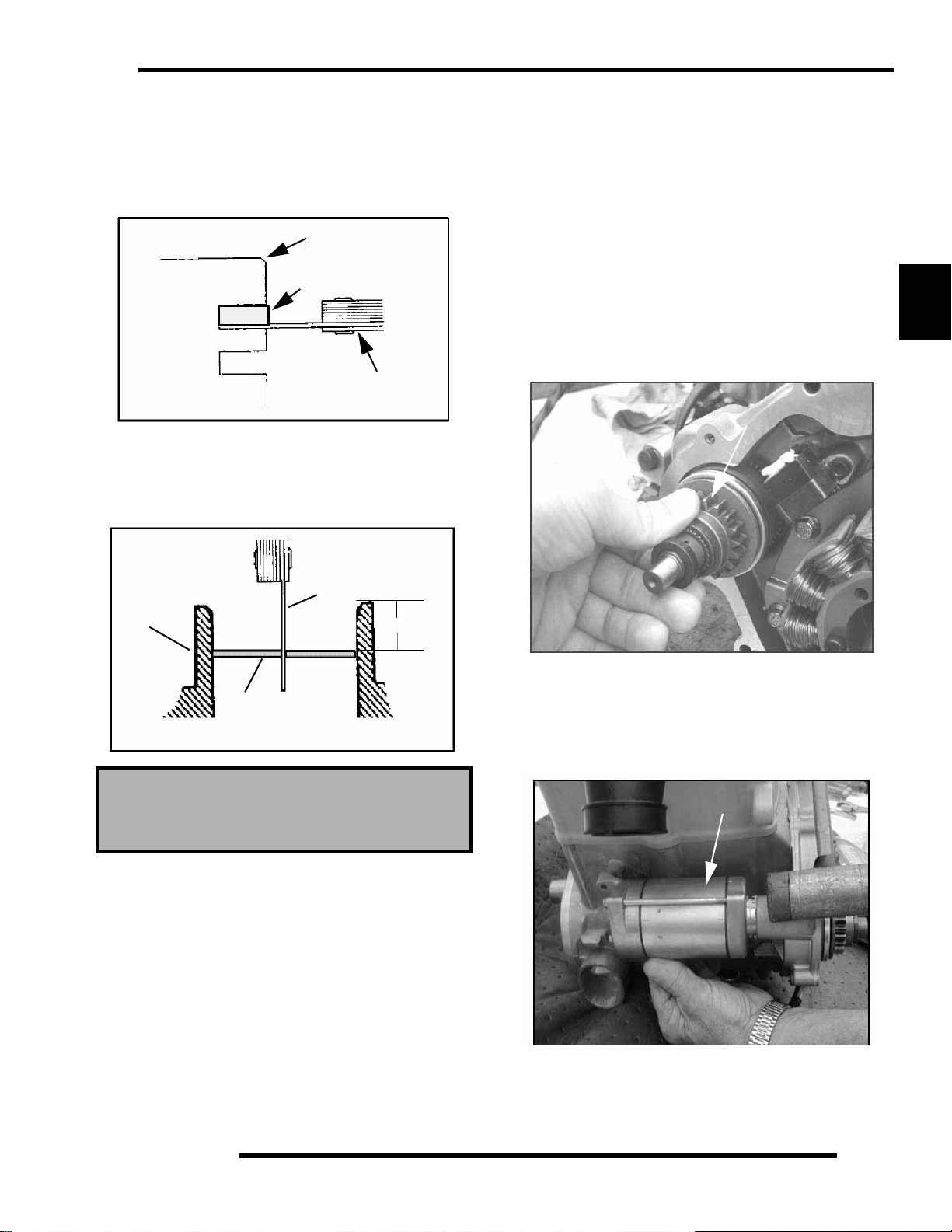
ENGINE
4. Measure piston ring to groove clearance by placing the ring
in the ring land and measuring with a thickness gauge.
Replace piston and rings if ring-to-groove clearance
exceeds service limits.
See “700/800 EFI Engine Service Specifications” on page 3.11
Piston
Ring
Feeler Gauge
Piston Ring Installed Gap
1. Place each piston ring (A) inside cylinder (B) using piston
to push ring squarely into place as shown. (See next page)
thoroughly with hot soapy water, rinsed, and dried
completely. Wipe cylinder bore with oil immediately
to remove residue and prevent rust.
Starter Drive/Bendix Removal Inspection
1. Remove stator housing bolts and remove housing.
2. Remove the flywheel nut and washer. Install Flywheel
Puller (PN 2871043) and remove flywheel.
NOTE: Do not thread the puller bolts into the
flywheel more than 1/4, or stator coils may be
damaged.
3. Remove starter bendix assembly (A). Note the thrust
washers located on both sides of the bendix.
B
3
C
B
A
25-50 mm
Piston Ring Installed Gap
See “700/800 EFI Engine Service
Specifications” on page 3.11
NOTE: Ring should be installed with the mark facing
upward.
2. Measure installed gap with a feeler gauge (C) at both the
top and bottom of the cylinder. REMINDER: A difference
in end gap indicates cylinder taper. The cylinder should be
measured for excessive taper and out of round.
3. If the bottom installed gap measurement exceeds the
service limit, replace the rings. If ring gap is smaller than
the specified limit, file ring ends until gap is within
specified range.
NOTE: Always check piston ring installed gap after
re-boring a cylinder or when installing new rings. A
re-bored cylinder should always be scrubbed
4. Inspect the thrust washer for wear or damage and replace
if necessary.
5. After the bendix is remo ved, tap on the starter assembly
with a soft faced mallet to loosen the starter from the
crankcase.
B
B
3.33
Page 90

ENGINE
6. Inspect gear teeth on starter drive (B). Replace starter drive
if gear teeth are cracked, worn, or broken.
7. Inspect the bendix bushing (C) in the mag cover for wear.
Replace as needed.
C
Flywheel / Stator Removal / Inspection
1. Remove stator housing bolts and remove housing.
3. Install Flywheel Puller (PN 2871043) and remove
flywheel (A). CAUTION: Do not thread the puller bolts
into the flywheel more than 1/4, or stator coils may be
damaged.
2871043
4. Use caution when removing the wire holddown (B), trigger
coil (C), and the stator assembly (D). Do not tap or bump
the gear /stator housing cover or the stator. This could
cause the seal around the gear/stator housing cover and the
crankcase to break, causing a leak.
A
2. Remove flywheel nut and washer.
Remove Stator
Cover
C
B
E
5. Remove the bendix (E) if necessary.
D
3.34
Page 91

ENGINE
Engine Crankcase Disassembly / Inspection
1. Remove the stator cover (A) and water pump cover (B).
B
A
2. Remove the nylok nut (C), washer (D), and water pu mp
impeller (E). Remove part of the water pump seal behind
the impeller.
4. Install Flywheel Puller (PN 2871043) and remove flywheel
(F). CAUTION: Do not thread the puller bolts into the
flywheel more than 1/4, or stator coils may be damaged.
3
F
5. Remove the starter ben dix (G), wire holddown plate (H),
and the woodruff key (I) from the crankshaft. The stator
does not have to be removed at this point.
I
H
E
C
3. Remove flywheel nut and washer.
G
D
6. Remove the gear/stator housing bolts and remove the gear/
stator housing cover (J) and gasket from the crankcase. Be
sure to catch the excess oil from the crankcase.
J
3.35
Page 92

ENGINE
7. Note the positions of the gears in the photo.
Camshaft Gear
Crank Gear
8. Use a white pen to accent the timing marks on the following
gears: camshaft gear (K), crankshaft gear (M), or
counterbalance gear (N) This will ensure proper gear
alignment and timing during reassembly of the gears.
Counterbalance Gear
K
Water Pump Gear
Timing Marks
10. Inspect the cam gear teeth and check to make sure there is
spring tension offsetting the teeth between the two gears.
If there is no tension, check the springs inside of the cam
gear assembly.
3 Loaded Springs
11. T he cam gear assembly contains three loaded springs. To
open the cam gear assembly:
* Place the cam gear on a flat surface with the timing mark side
facing up.
* While holding both gears together, lightly work a small
flathead screwdriver between the two gears.
N
M
NOTE: If replacing one of the gears, it is
recommended that all of the gears be replaced. A
gear kit is available in the parts book.
9. Use the Cam Gear Tooth Alignment Tool (PU-45497-2)
(O) to align the cam split gear assembly. With the split gear
aligned, remove the bolt and cam gear assembly.
NOTE: Install the Cam Gear Tooth Alignment Tool
(PU-45497-2) into the assembly hole counter
clockwise from the timing mark as shown.
* Remove the top gear. The springs should stay in place.
CAUTION
Wear safety glasses at all times. Use caution when
working with the top gear. The springs could cause
injury or become lost should they pop out.
12. Remove all three springs using one of the tapered pins from
the Tapered Pins (PU-45497-1).
3.36
Page 93

ENGINE
13. With a white marking pen, accent the timing mark on the
gear that contains the springs.
Accent Timing Marks
14. Inspect the gear teeth and the three tabs on the gears for
wear.
Inspect Teeth & Tabs
16. Insert the pointed dowels from the Tapered Pins (PU45497-1) into the cam gear.
3
PU-45497-1
To Assemble:
* Hold the spring with one finger.
* Start the pointed end of the tapered pin into the cam gear hole
and slowly push the dowel through the hole until the end of the
dowel is almost flush with the spring.
* Perform this procedure with all three tapered pins.
* Do not push the pins too far through or the springs will pop
out.
NOTE: Do not remove the tapered pins at this time.
Replace 3 Springs
15. Install the new springs into the grooves of the cam gear.
Install Springs
17. Note in the photograph that the Tapered Pins (PU-45497-
1) are below flush with end of the springs. This helps to
align the three gear tabs during the next step.
PU-45497-1
Cam Gear Spring Installation Tool Kit:
(PU-45497)
Tapered Pins: (PU-45497-1)
Cam Gear Tooth Align Tool: (PU-45497-2)
3.37
Page 94

ENGINE
18. Line up the two gears using the timing marks and the three
gear tabs that were referenced earlier. Push the gears back
together, using both hands and hold securely.
Align Timing Marks
19. Once the gears are pressed together, firmly hold the gears
together with one hand. Carefully remove the Tapered Pins
(PU-45497-1) by pulling them out one at a time with the
other hand.
NOTE: Install the Cam Gear Alignment Tool (PU45497-2) into one assembly hole counter clockwise
from the timing mark.
PU--45497-2
NOTE: For ease of installing the Cam Gear
Alignment Tool (PU-45497-2) (R), use a twisting
motion when pushing down on the tool.
21. To remove the balance shaft gear, the flat side of the
camshaft (P) must face the balance shaft gear. To rotate the
camshaft, use the Cam Spanner Wrench (PU-45498) to
rotate the camshaft so the flat side of the camshaft faces the
balance shaft gear.
20. After the tapered pins are removed, be sure the cam gear
assembly is held together tightly. Place the cam gear
assembly on a flat surface. Use the Cam Gear Tooth
Alignment Tool (PU-45497-2) to align the teeth of the cam
gears, as shown in the picture.
PU-45498
P
NOTE: This Cam Spanner Wrench (PU-45498) is
only needed to rotate the camshaft when the entire
valve train is assembled. If the rocker arms are
removed, the cam-shaft can be turned by hand.
3.38
Page 95

ENGINE
22. Remove the bolt and nut from the balance shaft gear. Try
to remove the balance shaft gear. If the gear does not come
off manually, use the Flywheel Puller (PN 2871043) to
remove the balance shaft gear.
2871043
23. Inspect the crankshaft gear (Q) for broken or worn teeth. If
the crankshaft gear does not need to be replaced, it does not
need to be removed. If the crankshaft gear is damaged,
remove the crankshaft gear with the Flywheel Puller (PN
2871043).
25. Install the Flywheel Puller (PN 2871043) and rem ove the
crankshaft gear, if needed.
2871043
3
26. Rotate the water/oil pump gear (S), so that all four bolts are
visible though the gear. Remove the four bolts with a hex
wrench. Pull out the pump.
S
Q
24. Install the two puller bolts (R). Tighten the puller bolts up
so that the bolts are at equal length.
R
27. Inspect the oil pump rotors for wear. Mark the rotors with
a white pen to ensure upon reassembly that the correct sides
of the rotors are installed and mesh with the same edges as
previously installed.
NOTE: If replacing the old rotors, new replacement
rotors will fit into the old oil/water pump housing.
3.39
Page 96

ENGINE
28. Use a feeler gauge to measure the clearance between the
two rotors. Measure the gap between the two rotor tips as
shown below. The clearance should not exceed 0.006"
(0.15 mm).
0.006” (0.15 mm)
Max Tip Clearance
29. Remove the oil pressure relief. The oil pressure relief
consists of a bolt, washer, spring, and valve (dowel).
Inspect the valve (dowel) for signs of possible obstructions.
Use compressed air to blow out any debris.
NOTE: Be sure to place the tapered end of the valve
(dowel) in first. If the valve is installed incorrectly,
oil pressure and oil priming problems will occur.
31. Carefully press the gear off the assembly while supporting
the housing assembly.
Press Off Gear
CAUTION
Wear appropriate safety gear during this procedure.
Protective gloves, clothing and eyew ea r are
required.
30. Reinstall the valve (dowel chamfered end first). Install the
spring, washer, and bolt. Torque to specification .
22 22 2 ft. lbs.
(30 3 Nm).
Chamfer
End First
32. Remove the snap ring from the assembly. Place the housing
in a support and press out the bearing/shaft assembly.
Press Out shaft
and bearing
assembly.
Bearing
Retaining Ring
3.40
= T
22 2 ft. lbs. (30 3 Nm)
Page 97

ENGINE
33. Place the shaft in a press to remove the bearing.
Bearing
34. Press shaft into the new bearing..
New Bearing
36. Press gear onto shaft while supporting the housing.
3
37. Remove thrust plate (U).
U
35. Press the bearing/shaft assembly using the bearing's outer
race. Do not use the shaft to press the assembly into the
housing, as bearing damage may result. Install retaining
ring.
Press Bearing/Shaft
Assembly using
outer race only
38. Remove PTO end engine mount Remove crankcase bolts.
Tap on the reinforced areas on the cases using soft hammer.
Carefully separate the two crankcase halves.
Separate
Crankcase Halves
3.41
Page 98

ENGINE
NOTE: Only remove the oil baffle if the baffle is
damaged. When removing the oil baffle bolts, use a
heat gun to heat the bolts and loosen the Loctite
This will prevent any possible damage to the bolts or
to the crankcase casting.
39. Remove and clean oil pick up (V) and oil baffle weldment
(W).
.
W
V
40. Remove balance shaft and crankshaft.
41. R emove and inspect crankshaft main journal bearings for
abnormal wear. It is recommended to replace the
bearings anytime the engine is disassembled.
NOTE: Plain bearing clearances may be checked
using a commercially available plasti-gauge
material.
Camshaft Inspection
1. Thoroughly clean the cam shaft.
2. Visually inspect each cam lobe for wear, chafing or
damage.
3. Measure height of each cam lobe using a micrometer.
Compare to specification.
3.42
Cam Lobe Height
= In. / mm.
Cam Lobe Height
(Intake & Exhaust):
Std: 1.3334" (33.8674 mm)
Page 99

ENGINE
4. Measure camshaft journal outside diameters (O.D.).
C
B
A
= In. / mm.
Camshaft Journal O.D. :
A. (Mag): 1.654" ± .00039" (42 ± .010 mm)
B. (Ctr.): 1.634" ± .00039" (41.50 ± .010 mm)
C. (PTO): 1.614" ± .00039" (41 ± .010 mm)
5. Measure ID of camshaft journal bores.
ENGINE REASSEMBLY
CRANKCASE REASSEMBLY
CAUTION
After any reassembly or rebuild, the engine must be
primed using the Oil Priming Adapter (PU-45778)
and a 3/4-full oil filter before initial start-up. Follow
Steps 45-46 of this section to prime the engine and
to help aid proper break-in.
NOTE: Before assembly, clean the bolts and bolt
holes with Primer N (PN 2870585) to remove any
debris. This will ensure proper sealing when
installing bolts.
1. Install oil pick up (A), if removed. Torque to specification.
B
A
3
= In. / mm.
Camshaft Journal Bore I.D.:
(Mag): 1.656" ± 0.00039" (42.07± 0.010 mm)
(Ctr.) 1.637" ± 0.00039" (41.58 ± 0.010 mm)
(PTO) 1.617" ± 0.00039" (41.07 ± 0.010 mm)
6. Calculate oil clearance by subtracting j ournal O.D.'s from
journal bore I.D.'s. Compare to specification.
= In. / mm.
Calculated Camshaft Oil Clearance:
Std: 0.0027" (.070mm)
Limit: .0039" (.10 mm)
NOTE: Replace camshaft if damaged or if any part is
worn past the service limit.
NOTE: Replace engine block if camshaft journal
bores are damaged or worn excessively.
2. Install oil baffle weldment (B). Torque bolts to
specification.
= T
Oil Baffle Weldment &
Oil Pick Up Bolt Torque:
60 ± 6 in. lbs. (6.8 ± 0.68 Nm)
3. Install the balance shaft. Inspect balance shaft clearance
(C) in both gearcase halves. Rotate balance shaft to ensure
that there is clearance between it and oil baffle weldment.
3.43
Page 100

ENGINE
NOTE: Always install new balance shaft bearings.
C
4. Apply assembly lube to cam journals and balance shaft
bearing surfaces of the MAG case halve. Install cam and
balance shafts.
6. Apply Crankcase Sealant (PN 2871557) to the top gearcase
halve.
NOTE: Do not apply sealant to cam relief hole (E).
E
7. Assemble the crankcase halves. Apply LocTite™ 242 (PN
2871949) to the threads and pipe sealant to the bolt flanges.
Torque bolts to specification following torque pattern at
beginning of this chapter.
5. Install crankshaft assembly and app ly engine oil to crank
pins and rods (D). Apply assembly lube to the main
journals and bearings.
= T
Crankcase Bolt Torque:
22 + 2 ft. lbs. (30 + 3 Nm)
Torque in sequence
8. Lubricate cam lobes and valve lifters with Moly Lube
Grease.
Apply Moly Lube Cam Lobes
Lifters
3.44
D
 Loading...