

Page 1
Simple Move 101
CANTILEVER GATE DRIVE UNIT
EN
Page 2

TABLE OF CONTENTS
INTRODUCTION ................................................................................ 3
SAFETY PRINCIPLES ....................................................................... 3
PRODUCT DESCRIPTION ................................................................4
Components of the set 4
Gate dimensions and maximum weight 5
Drive dimensions (in mm) 5
Pictorial view of installation 6
EN
Technical data 6
PRELIMINARY OPERATIONS ..........................................................7
Checks before installation 7
Required tools 7
Preliminary wiring system 8
Safety rules 8
1. PREPARATION OF THE FOUNDATIONS .....................................9
2. MOUNTING .................................................................................. 10
3. ELECTRICAL CONNECTIONS ...................................................14
4. QUICK START-UP .......................................................................16
5. FITTING THE SHIELDS .............................................................. 17
OPERATIONAL USE .......................................................................18
Operation in sequential mode 18
Operation in automatic mode 19
Operation of obstacle detection function 19
Operation of zone lighting 19
Operation of remote controls or transmitters with 3 push-buttons 20
Drive Unit unlocking / blocking 20
ADVANCED PARAMETER SETTING .............................................21
Available push-buttons on remote controls with 2 or 4 push-buttons 21
Programming of a remote control with 2 or 4 push-buttons 21
Programming of a remote control with 3 push-buttons 21
Activation of the function of opening for pedestrian entry 22
Activation of the AUTOMATIC CLOSING mode 22
ACCESSORIES ...............................................................................23
SOLAR ENERGY SUPPLY .............................................................. 31
TROUBLESHOOTING ..................................................................... 32
2
Page 3

INTRODUCTION
POLARGOS is a Polish manufacturer of housing and industrial fence systems as well as other steel products that
has been operating on the market since 1994.
Due to their many years of experience as well as production and marketing facilities, POLARGOS manufactures
products for numerous domestic and foreign customers.
Our aim is the delivery of products that both meet the highest workmanship standards and answer customers’
expectations as regards to the aesthetics and ruling trends in the fencing market.
Thank you for your condence in choosing Simple Move 101.
Please read this instruction book thoroughly before installation.
Simple Move 101 is manufactured by Somfy for POLARGOS.
SAFETY PRINCIPLES
Please read this instruction book thoroughly before installation of the drive unit. It is important to follow the
instructions precisely and retain this document for the whole working life of the product.
In Failure to comply with the recommendations concerning installation could lead to severe physical injuries
or material damage. POLARGOS shall not bear responsibility in such cases.
This device is not designed to be used by people (including children) with limited physical, sensory or mental
abilities, or by people without any experience or knowledge unless under the supervision of the person
responsible for their safety or using instructions provided as regards the operation of this device.
Children are not allowed to play with fixed control devices.
Remote control transmitters must be kept out of the reach of children.
When using a switch without an interlock***, check if another people are at a suitable distance from the gate.
Check the installation frequently to detect any abnormalities connected with the gate balance or specify signs
of wear. Do not use any drive units that need to be repaired or adjusted.
Disconnect the power supply from the drive unit before performing cleaning or any other maintenance work.
Before installation of the drive unit, check if the drive unit moving parts are in good technical condition,
balanced properly and if the gate opens and closes in a correct manner.
Do not stand between the moving part and near fixed elements in view of the dangers connected with
displacement of the moving parts during opening (crushing, cropping, blocking).
Watch the gate while it is in motion.
All switches without interlock*** must be in the area from where the moving part will be directly visible but at a
suitable distance from moving elements. The switches must be installed at a height of at least 1.5 m; they cannot
be generally accessible except for the switches requiring the use of a key. When using these switches, check to
see if any person is in the vicinity.
EN
3
Page 4
When the gate is completely open, keep a distance of 500 mm from its end.
After installation is nished, check the correct adjustment of the mechanism and proper operation of the safety
system and any devices used to switch off the system manually.
.
Do not throw away unwanted devices or expired batteries together with household waste. Consumers
are obliged to transport all unwanted electronic and electric equipment to a special waste collection area
for their disposal and recycling.
PRODUCT DESCRIPTION
The drive unit is designed for cantilever gates used in residential properties.
EN
Components of the set
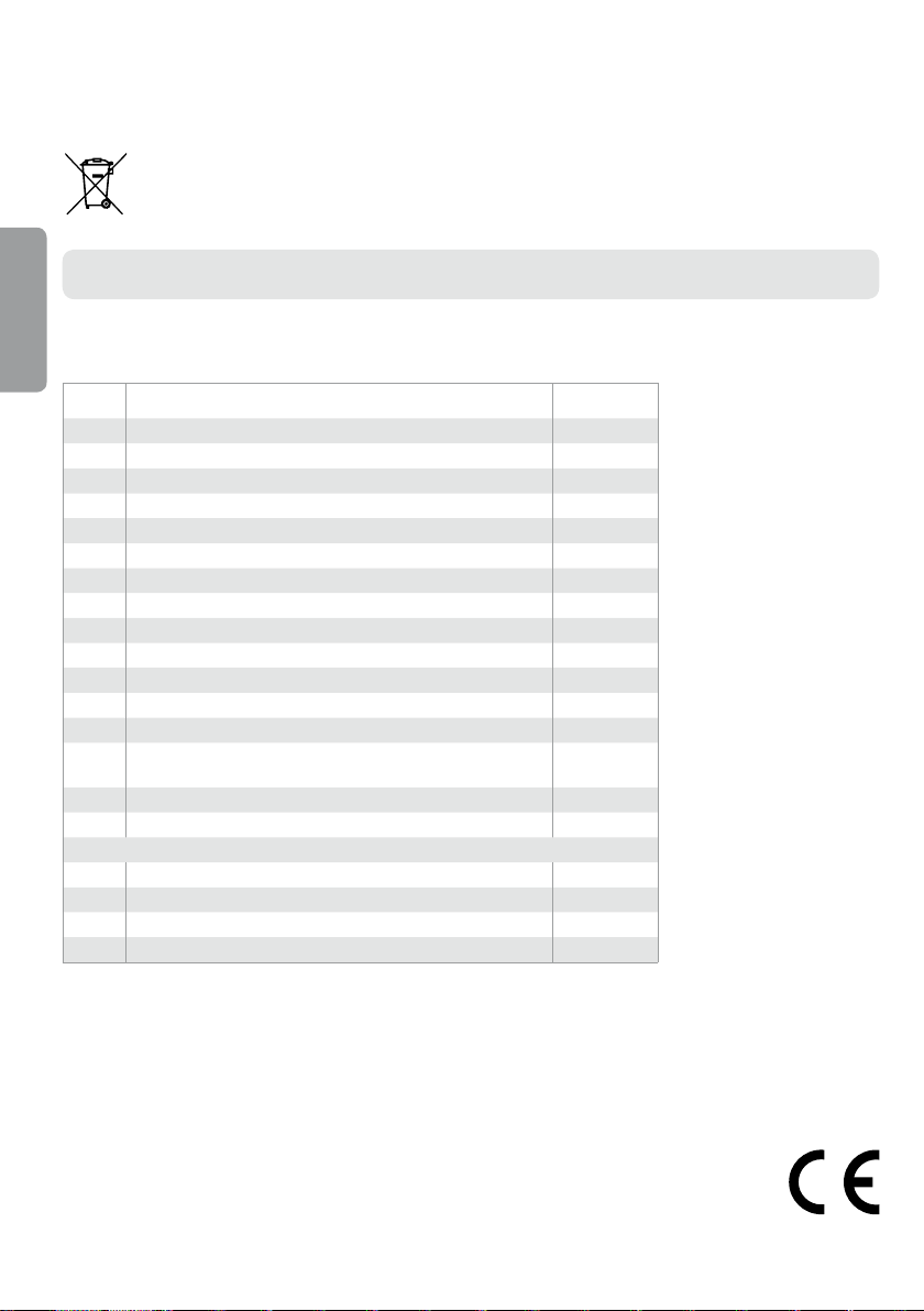
Item Name Quantity
1 Shield 1
2 Antenna 1
3 Electronic module 1
4 Drive 1
5 Shield screw 1
6 Round gasket 9x2 1
7 Toothed bar 33 cm 13
8 Cable bush 1
9 Thread forming screw TCB M4x10, galvanized 3
10 Fan-shaped washer AZ4 1
11 Wire holder 1
12 Flat medium washer M4x10 1
13 Round insulated terminal D4 1
Assembly template (printed on cardboard)
14
to be cut out
15 Adhesive label for the electronic module 1
16 Remote control transmitter 1
Additional items to be provided by the user:
17 Nuts M10, galvanized 8
18 Flat washers 10.5x22x2, galvanized 8
19 Double-thread screw 10x15 mm 4
20 Pin 10x60 S12 4
1
POLARGOS hereby declares that this product conforms to the basic requirements and other relevant regulations of
the Directive 1999/5/CE. The Declaration of Conformity is available at www.polargos.eu
This product is accepted for use in European Union and Switzerland..
*** example: intercom, key switch, code panel, etc.
4
Page 5
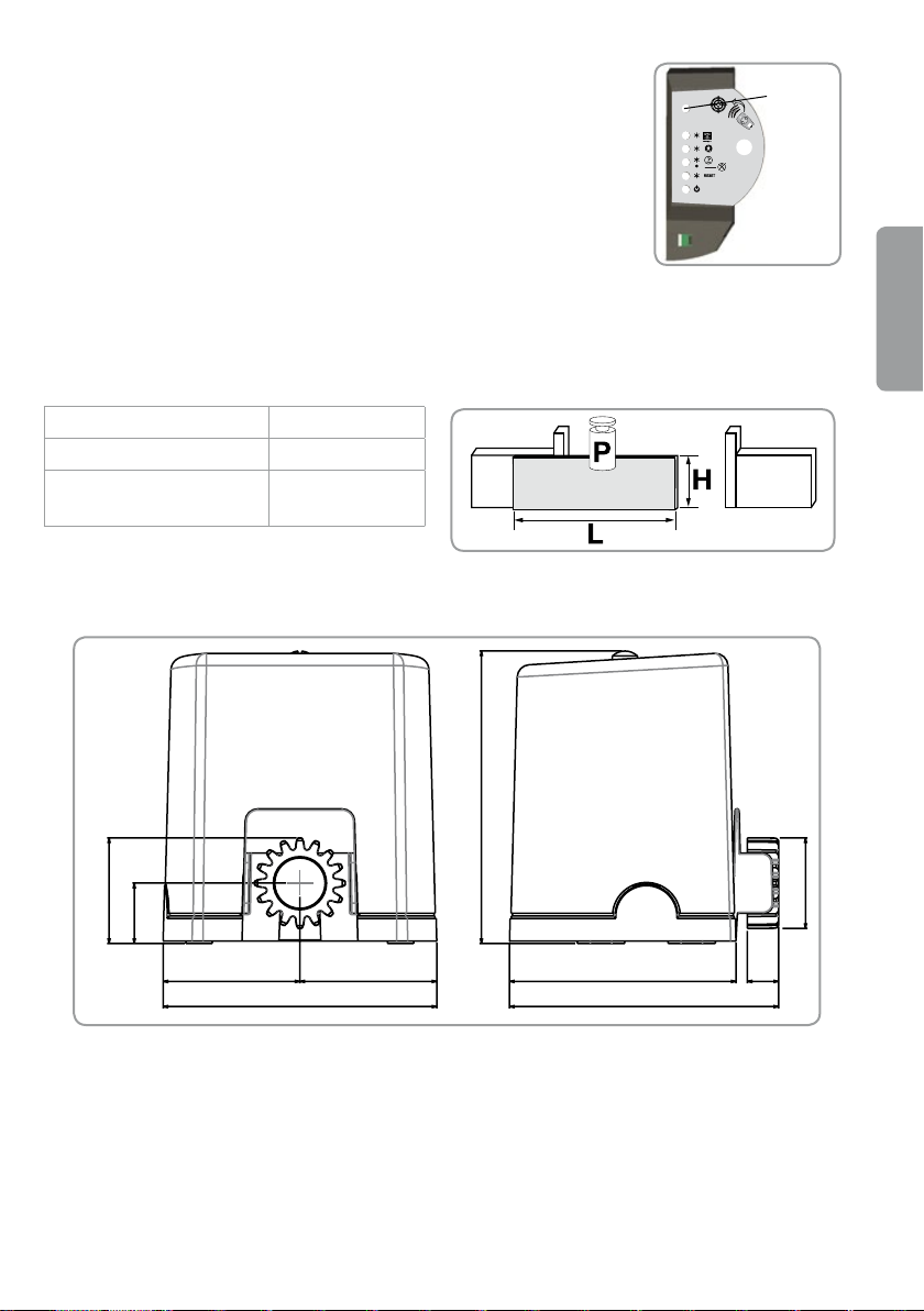
Light sensor
84
72
232
48
109
218 214
109
180
25
The electronic module of the drive is equipped with a light sensor that detects the
presence or absence of the shield. Thanks to this function, the setting mode is
available only with the shield removed. If the shield is installed, the drive is switched
to standby mode.
Gate dimensions and maximum weight
Maximum weight (P) 300 kg
Maximum height (H) 2 m
Maximum width (L)
Gate 4M
Overall length with
counterbalance 6 m
Drive dimensions (in mm)
Light
sensor
EN
5
Page 6
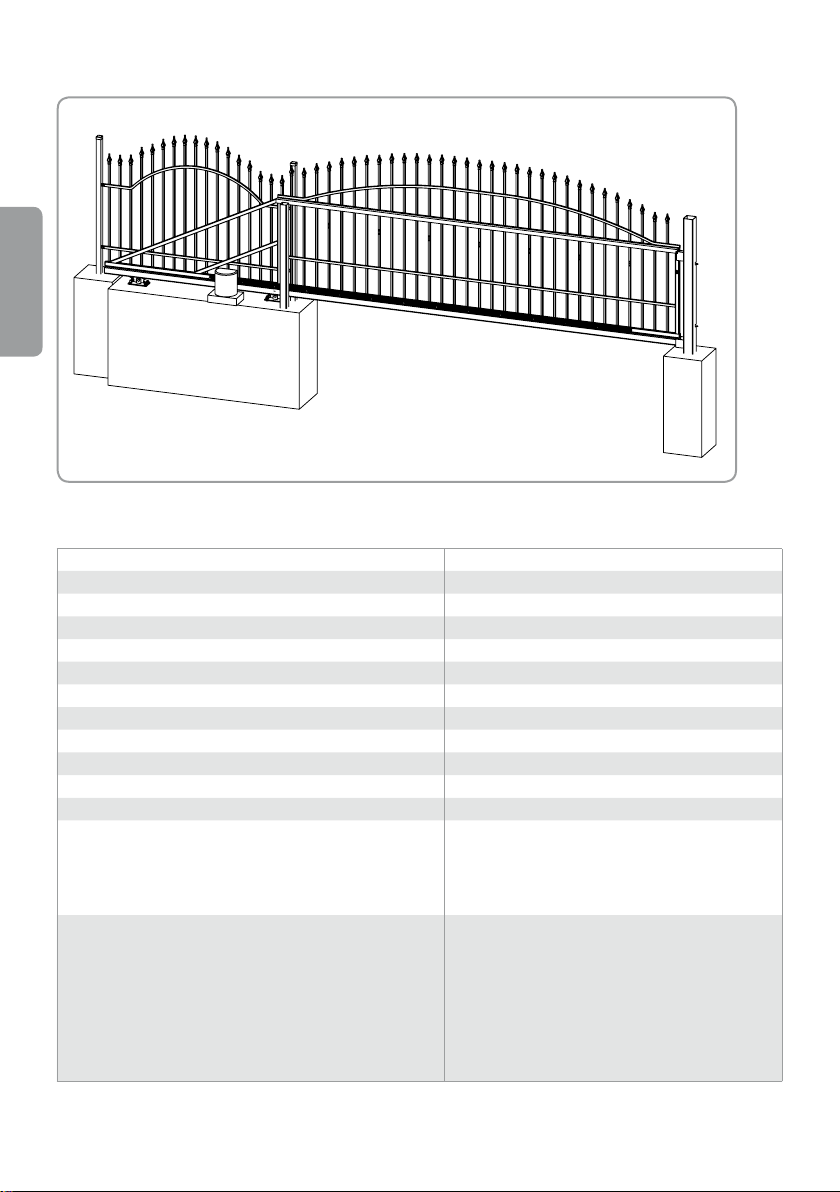
Pictorial view of installation
EN
Technical data
Supply voltage 230 V AC / Solar energy
Drive type 24 V DC
Drive power 150 W
Maximum energy consumption (including zone lighting) 600 W
Energy consumption in stand by mode 4,5 W
Average number of working cycles daily 20 cycles daily
Opening speed* 3 m / 16 s, beyond the deceleration area (20 cm)
Automatic obstacle detection According to EN 12 453
Working temperature Between -20C and +60C
Thermal shield Yes
Protection level IP 44
Built-in radio wave receiver Yes
Remote controls:
Radio frequency
Range of operational use
Number of memory settings
Possible connections:
Orange light output
Zone lighting output, supplied terminals
Accessory supply output
Emergency battery input
Photocell input
Control input, supplied terminals
433,42 MHz
~50 m
16
Flashing, 24 V, 10 W
Maximum 500 W (at 230 V AC)
24 V – 15 W as maximum, only at 230 V
Yes
Yes (BUS)
Yes, only at 230 V
* Opening time may differ depending on gate parameters.
6
Page 7
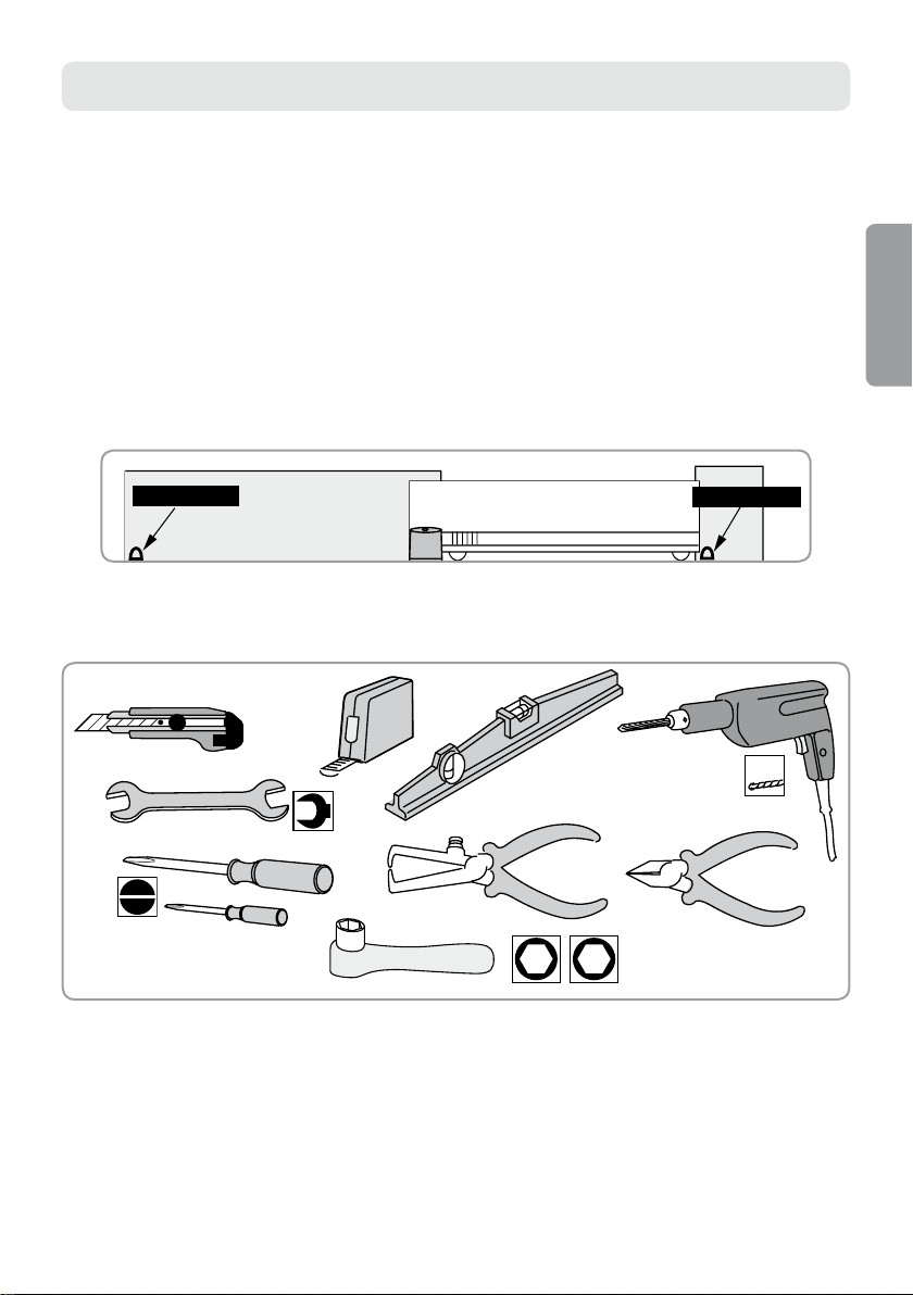
PRELIMINARY OPERATIONS
Opening stop
Closing stop
17
12
13 10
Checks before installation
► Gate inspection
The gate must be in good technical condition: check if its construction allows automation.
The gate must be in a horizontal position during the whole displacement cycle; it must open and close
without the necessity of using excessive power. Check if the guide is absolutely perpendicular to the ground
and if there are no obstructions that could prevent proper gate displacement.
►The presence of gate stops
Gate movement must be controlled by stops rmly xed to the ground. The stops limit the extreme position
of the gate during opening while the post performs this function during closing.
Necessary tools
EN
7
Page 8

Preliminary wiring system
Provide the shield Orange ICT Ø 25 mm for cables located underground.
If cables cannot be laid underground, use a cable bush that can withstand being run over
by vehicles.
►Mains supply (only with voltage 230 V)
Lead power supply of 230 V as close to the drive unit as possible.
The electronic module of the drive must be powered with voltage 230 V – 50 Hz using a exible conductor
of 1,5 mm².
The electrical supply line must be:
EN
• Designed for the drive only.
• Protected:
– by means of a fuse or a circuit breaker 10 A,
– by means of a differential gear (30 mA).
• Installed in accordance with the safety standards concerning wiring systems and effective in the country
of use.
Multipolar disconnection of power supply is to be provided:
• using a supply conductor with a plug,
• or by means of a switch where the distance between contacts is at least 3 mm for each pole (according
to EN 60335-1).
It is recommended to install a lightning rod (maximum residual voltage 2 kV).
►Photocells (an option in Simple Move 101 set)
Photocells are necessary for operation in automatic mode and to open a gate.
• Photocell conductors (see page 23).
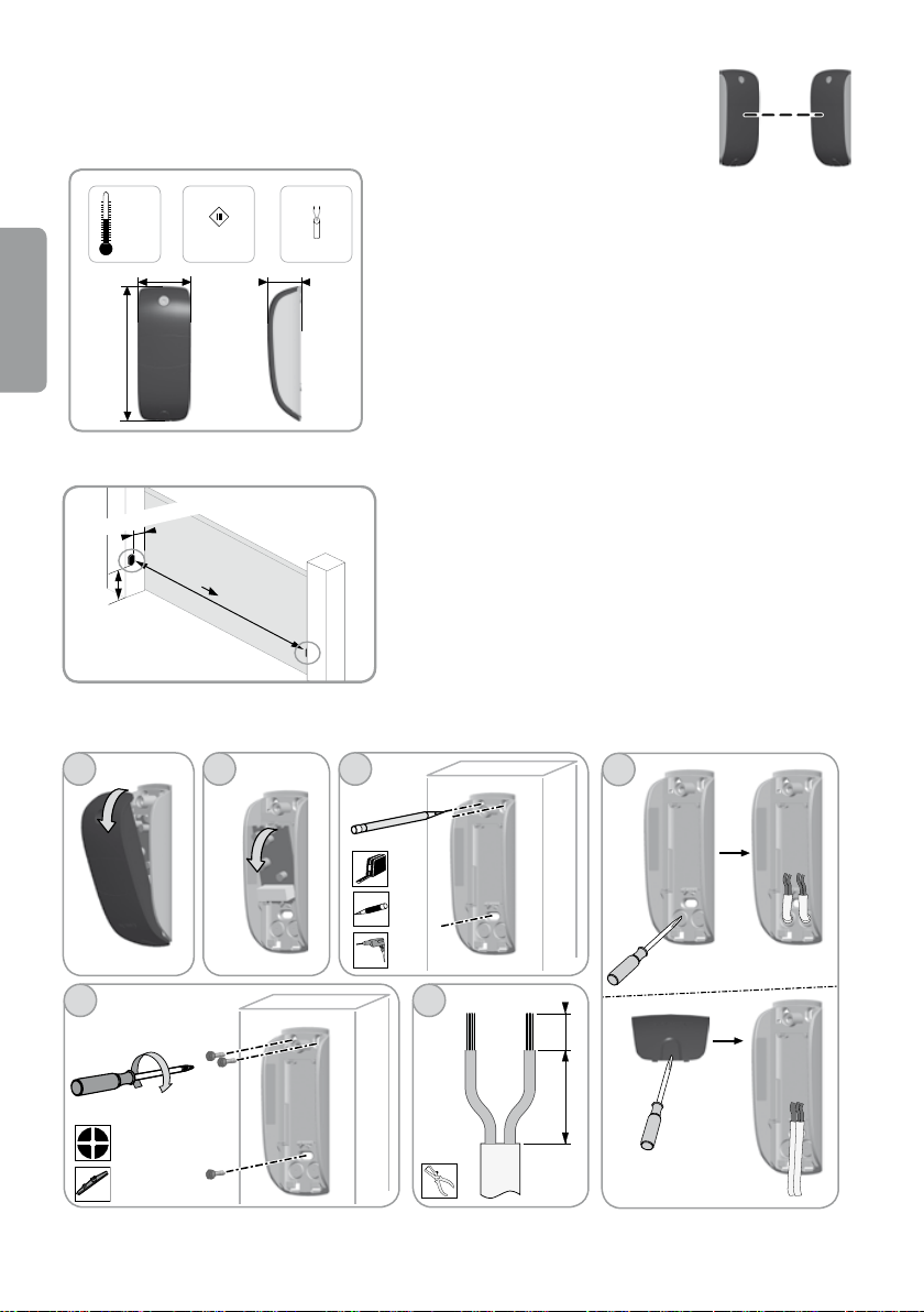
Provide a connection for the photocell conductors in the shield between the two gate posts. Drill holes
for shields in both ends of the gate construction. The photocells must be connected with the electronic
system of the gate using a cable 2x0.75 mm². Supply conductors must be led under the photocells.
• Location of the photocells (see page 23).
►Orange light (option)
Installation of orange light is recommended for operation in automatic mode when opening the gate.
• Orange light conductors (see page 27).
Provide space for the conductor of the orange light. The orange light must be connected to the
electronic system of the drive using a conductor 2x0.75 mm².
• Location of the orange light (see page 26).
Safety rules
Observe the following safety rules during installation:
• Remove any jewellery before commencing installation (bracelets, chains or any other items).
• Wear special safety goggles and proper protection during drilling or welding.
• Use the appropriate tools as specied on page 6.
• Exercise caution during operation of the drive system to avoid the risk of injury..
• Do not connect the system to the mains or emergency battery (accessory equipment) before installation
is completed.
• Do not use high pressure water to clean the system.
8
Page 9
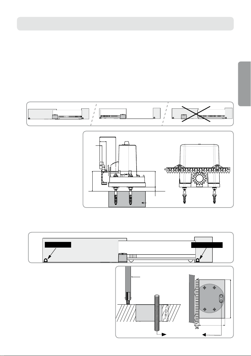
1. PREPARATION OF FOUNDATION
250 mm min
200 mm min
Gate
Foundation
Foundation
Toothed bar
Space for cables
Gate
Opening stop
Closing stop
75 do 80
Base
32
12
> 97
> 20
77
<100
Successive stages
• Drive Unit location
• Installation of stops
• Foundations
►Drive unit location
Horizontal setting
Pay attention to the fact that that the drive unit must be always within the area of the gate operation, during
both opening and closing.
Vertical
setting
The drive unit should be
located a little off the ground
(more than 20 mm).
Choose a suitable position for
the toothed bar. If necessary,
create a concrete base. It is
necessary to take into account
the gate position on trolleys.
EN
►Installation of stops
The gate movement must be controlled by stops xed to the ground rmly to limit the extreme position of the gate.
►Foundations
Screws to fasten the drive unit must be rmly
attached to the ground.
The foundation type and dimensions depend
on the type of ground.
The supply conductor must be laid according to
the standards concerning wiring systems and
effective in the country of use.
9
Page 10
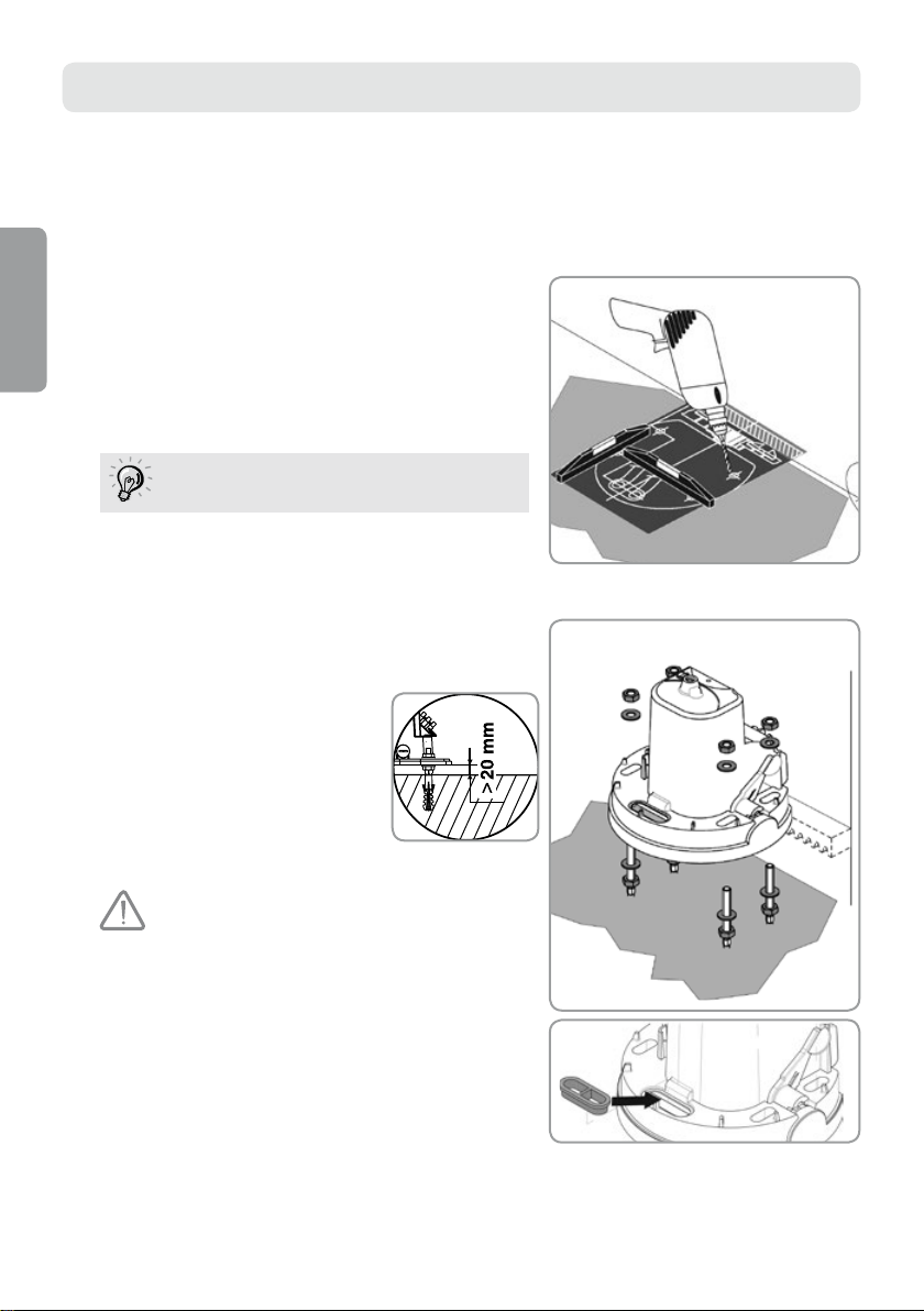
2. FASTENING
Successive stages
• Screw assembly
• Drive fastening
• Toothed bar assembly
• Mechanical adjustment
►Screw assembly
[1]. Place the assembly template on the ground (the template
EN
is printed on cardboard) and drill holes using a drill (Ø 12
mm) suitable for the ground type. (20)
[2]. Insert the pins (12x60 S12). Tighten the double-
thread screws (M10x15). (19)
Put a small amount of grease on the screws
before screwing them into the pins.
►Drive fastening
[1]. Screw in 4 nuts (M10, galvanized (17)) and put 4 washers
(at, Ø10 5x22x2, galvanized). (18)
[2]. Remove the shield (1) from
the drive (4).
[3]. Place the drive on screws:
the ange (drive basis) must be at
a maximum height of 25 mm
above the ground as.
The recommended distance
is between 20 and 25 mm.
Use a level to check if the drive is
positioned correctly.
[4]. After the drive is set at a suitable height from
the ground, attach it using washers (flat, Ø10 5x22x2,
galvanized) (18) and 4 nuts (M10, galvanized). (17)
[5]. Insert the cable bush (8) that has been drilled through
previously in the hole provided for the supply conductor.
10
Page 11
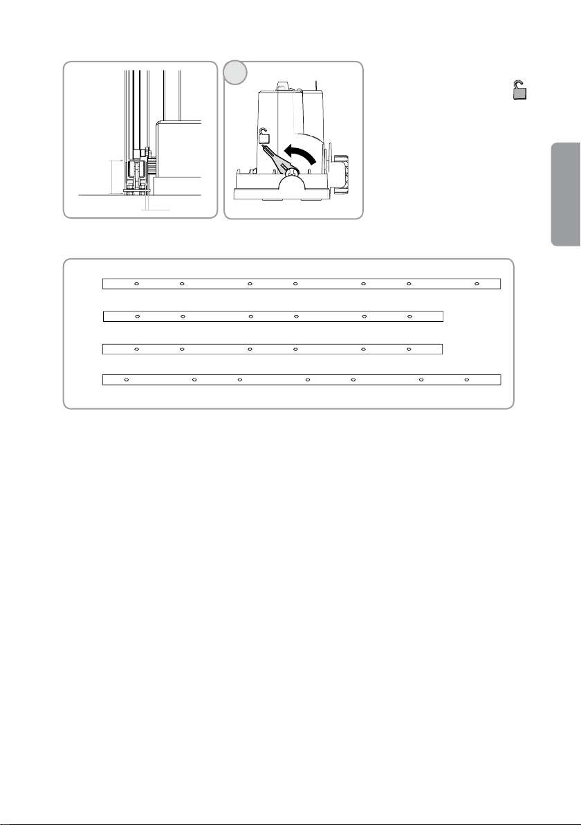
►Tooth bar assembly
77
11 -04
No. 1
No. 2
No. 3
No. 4
1
[2]. Preparation of bars.
[3]. Assembly of the bars should start from the lock side.
[4]. Insert bar No. 1 at a suitable distance from the lock side.
[5]. Fix the toothed bar (7) to bar No. 1 and fasten using screws M6x50.
[1]. Check if the drive is really unlocked
when the lever is in position .
EN
11
Page 12
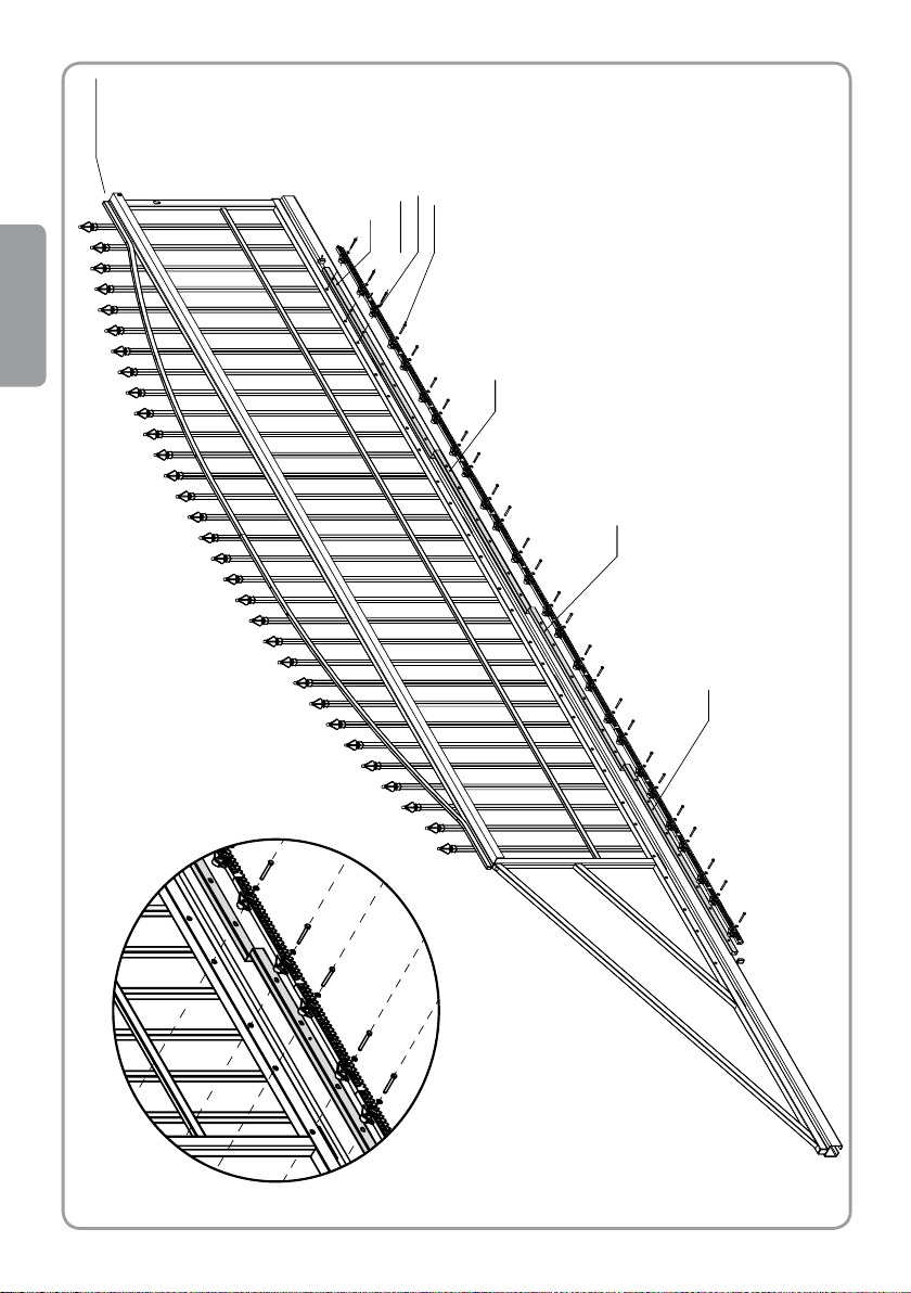
Toothed bar
Washer M6
Bar No. 2
Start
of assembly
Bar No. 3
Bar No. 1
Screw M6x50
Bar No. 4
lis
EN
12
Page 13
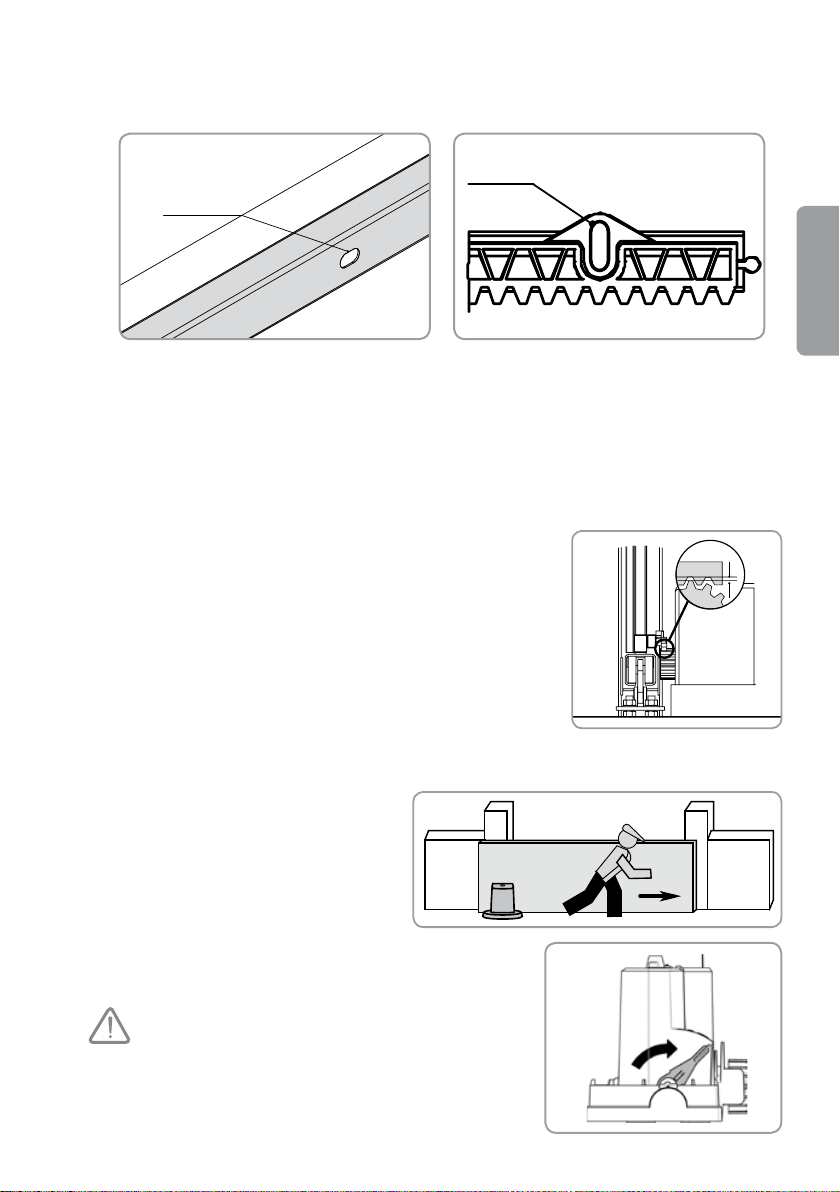
1,5/2 mm
Fasten the rst bar in such a way as to feel slight resistance.
Bean-shaped
element
for horizontal
adjustment
Bean-shaped element
for vertical adjustment
[6]. Level the bar. The bars No. 1 – No. 4 have bean-shaped elements for horizontal adjustment; The toothed
bars can be adjusted vertically.
[7]. Fasten the next toothed bars to the bar No. 1. The last toothed bar on the bar No. 1 will connect the bars
No. 2 and No. 1.
[8]. Fasten the next bars and toothed bars as above.
[9]. Once the bars are fastened, check whether everything is level or not; if not, correct this.
►Mechanical adjustment
Check if:
• the drive unit is located at a suitable height,
• the gate moves properly: the gate should move without difculty
along its track,
• the gear wheel is driven all the time when the gate moves along
its track,
• the set consisting of the toothed bar and the gear wheel does not
change its position substantially along the gate path.
If these conditions are not met:
[1]. Adjust the height and set the drive at a suitable level using the 4 nuts (17) located under the drive.
[2]. If necessary, adjust the position of the
toothed bar and tighten up the nuts of the
drive.
[3]. Close the gate.
[4.] Lock the drive.
EN
Never lock the drive when the gate
is running.
13
Page 14
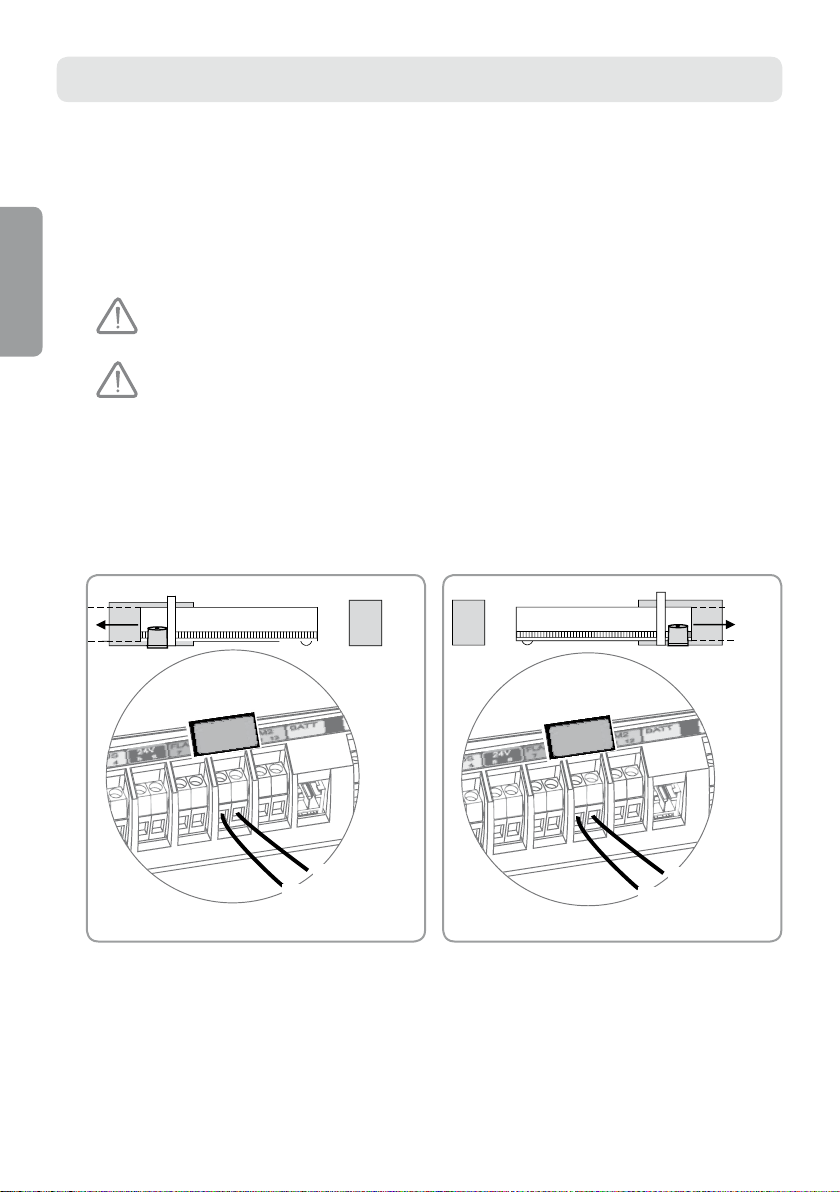
3. ELECTRICAL CONNECTIONS
Blue/Black
Brown/Green
9
10
M1
Blue/Black
Brown/Green
9
10
M1
Successive stages
• Connection of the drive unit
• Connection to power supply
• Connection to a solar energy source
• Connection of safety accessories
►Connection of the drive
EN
Always connect the drive unit and the electronic module before the
electronic module is connected to the mains.
Always connect the drive unit to the terminals 9 and 10 (green label M1
of the electronic module of the drive).
The drive unit (4) and the electronic module (3) are initially equipped with conductors designed for the drive
unit mounted on the left hand side. To change direction of the drive unit operation, interchange the conductors
connected to terminals 9 and 10.
The drive on the left-hand side
View from inside
The drive on the right-hand side
View from inside
14
Page 15
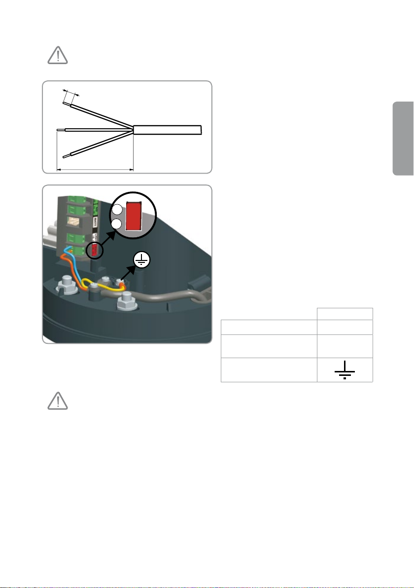
►Connection to power supply
15
16
230V
N
P
8 mm
75 mm
For safety reasons, only carry out these activities with the power supply
disconnected.
[1]. Skin the wires of the supply conductor (the
same length for 3 wires).
[2]. Connect the earth conductor.
The earth conductor (green-yellow) and the
insulated terminal provided (13) will be needed
in case of some accessories (lighting 230 V,
Class I).
[3]. Connect the phase conductor P and the
neutral conductor to terminals 15 and 16 of the
electronic module (red label 230 V).
Check whether the conductors are blocked
correctly by pulling them slightly.
Terminal
Blue conductor N 15
Red/brown/black
conductor
Green-yellow conductor
P 16
EN
It is obligatory to observe the recommendations concerning the colours
of conductors.
►Connection to a solar energy source (See page 30)
►Connection of protecting accessories
Photocells (to be sold separately as an option in the set Simple Move 101)
(See pages 23 and 24)
The photocells must be xed and connected before the start-up of the drive unit.
The orange light (to be sold separately as an option in the set Simple Move 101)
(See pages 26 and 27)
15
Page 16
4. QUICK START-UP
1
2
Successive stages
• Introduction to the remote control
• Placing the label on the electronic module
• Power up the system
• Gate track teaching
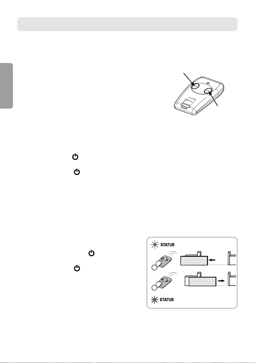
►Introduction to the remote controls
EN
The remote controls delivered in the set have been already programmed.
Push-button 1 of the remote control allows the complete opening
of the gate.
►Placing the label on the electronic module
Stick the label (14) on the electronic module (3) of the drive unit.
►Power up the system
Power up the system.
The STATUS indicator
drives is ON and they are waiting for adjustment.
If the STATUS indicator
on the electronic module ashes (2 pulses) to inform that the power supply of the
remains unlit, see page 31.
►Gate track teaching
The electronic system of the drive stores automatically the following:
• The necessary drive torque to control the gate in the usual mode. The saving of this information
allows detection of any abnormalities in the drive unit operation.
• The gate tracks during the opening and closing of the gate completely as well as the positions of the stops.
During setting the parameters, stand at the usual distance from the gate and carry out the following operations:
Push-button 1
Push-button 2
Press push-button 1 of the remote control to
open / close the gate COMPLETELY.
The STATUS indicator
module should EMIT LIGHT CONTINUOUSLY.
If the STATUS indicator ashes, see troubleshooting on
page 31.
Do not interrupt the gate movement (complete opening /
closing).
If the gate movement is interrupted, teaching will be
resumed automatically at the next opening.
16
of the electronic
Page 17
5. SHIELD ASSEMBLY
2
6
5
1
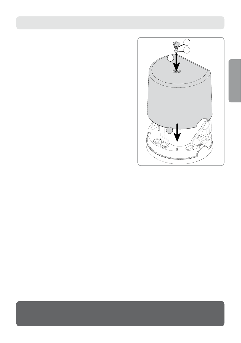
Check if the drive unit is locked.
[1]. Place the shield on the ange (base) of the drive.
[2]. Mount the gasket (6) to ensure the tight tting of the drive
unit and then the shield screw (5).
EN
According to the default settings, the drive unit operates in sequential
THE DRIVE UNIT IS READY FOR ACTION.
mode and in complete opening mode only.
17
Page 18
OPERATIONAL USE
1m
Operation in sequential mode
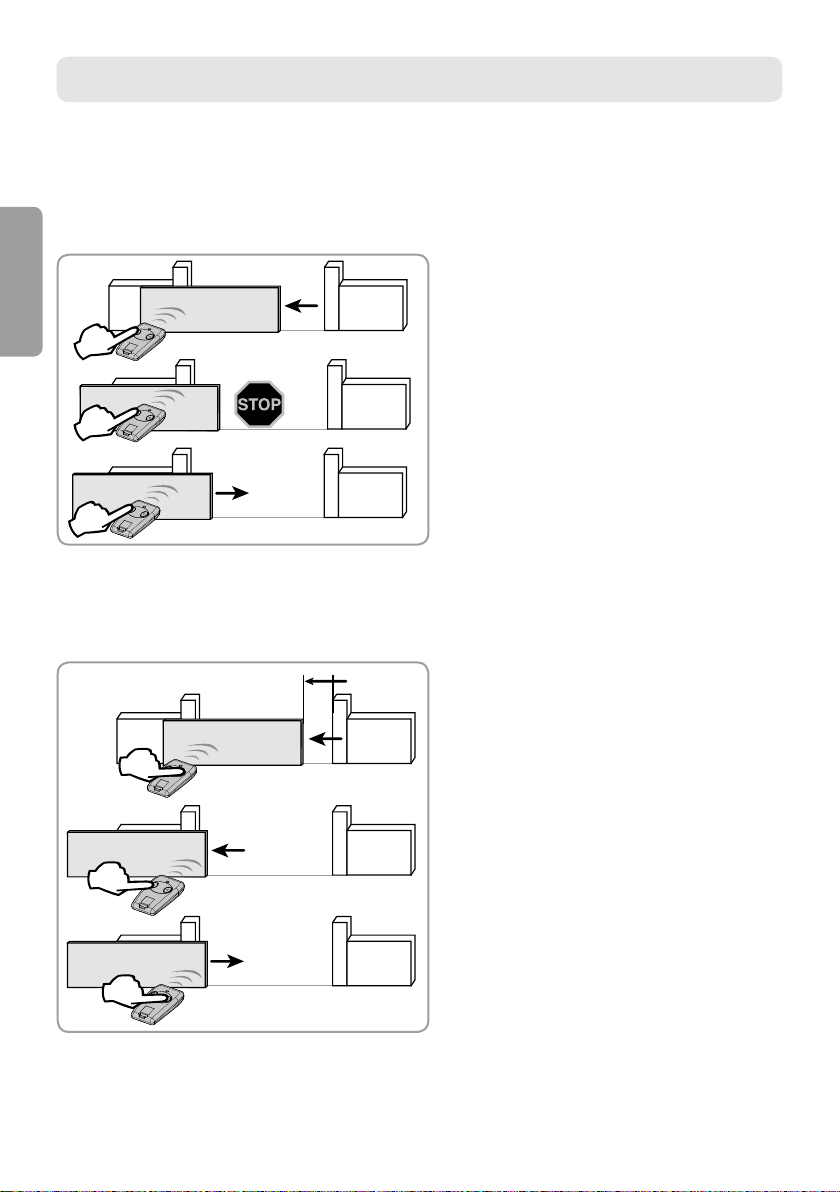
Successive pressing of the same push-button on the remote control results in the following drive unit operation:
Opening, Stop, Closing, Stop, Opening, etc.
►Complete opening
EN
Complete opening of the gate by pressing
push-button 1.
Stop the gate movement by renewed pressing of
push-button 1.
Close the gate by renewed pressing of pushbutton 1.
►Opening to allow pedestrian entry
Opening to allow pedestrian entry is carried out by pressing the previously activated
push-button on the remote control (see page 21).
Partial opening of the gate (about 1 m) by
pressing of the active push-button.
Complete opening of the gate by pressing
push-button 1.
Closing of the gate by renewed pressing of the
active push-button.
18
Page 19
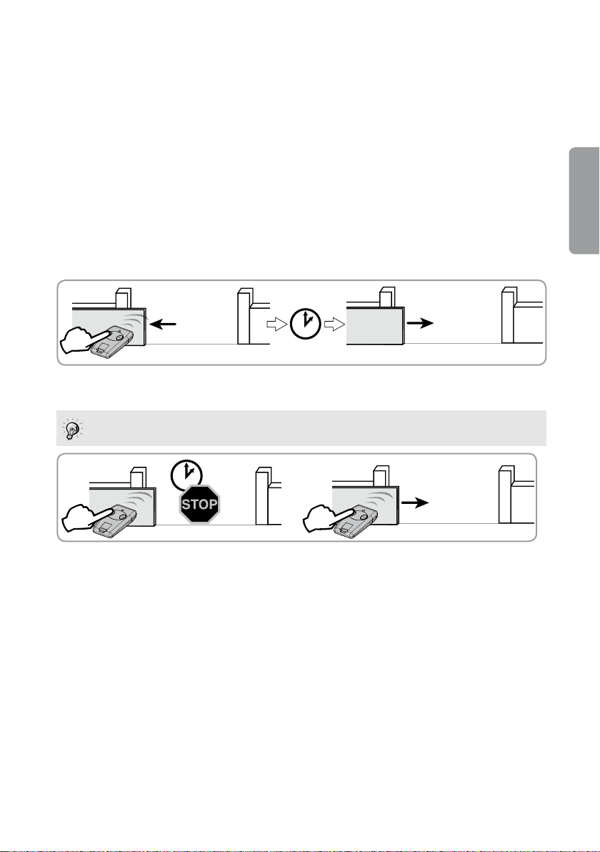
Operation in automatic mode
In automatic mode, the gate closes automatically after 30 seconds.
►Precautions
For automatic operation, installation of the photocell set is necessary according to EN 12 453 (see
description and information on conductors on pages 22 and 23).
Polargos recommends installation of the orange light (see description and information on conductors on
pages 26 and 27) and the zone lighting (see information on conductors on page 27).
►Operation in automatic mode (to switch on this mode, read the
information on page 20)
In automatic mode, the gate closes automatically after 30 seconds.
In case an obstacle is detected during closing, the gate stops and then opens completely. To close the gate, press
push-button 1.
EN
Gate opening by pressing push-button 1.
Crossing in front of the photocells will result in automatic gate closing
after 5 seconds.
Keeping of the gate in the open
position by pressing push-button 1.
Automatic gate closing after 30
seconds.
Automatic gate closing by renewed pressing
of push-button 1.
Operation of the obstacle detection function
In case an obstacle is detected:
• during opening: the gate stops and carries out a short movement backwards,
• during closing: the gate stops and then it opens fully.
Operation of zone lighting
The zone lighting lights up every time when the drive is started. It goes out automatically after 1 minute and 30 seconds.
19
Page 20
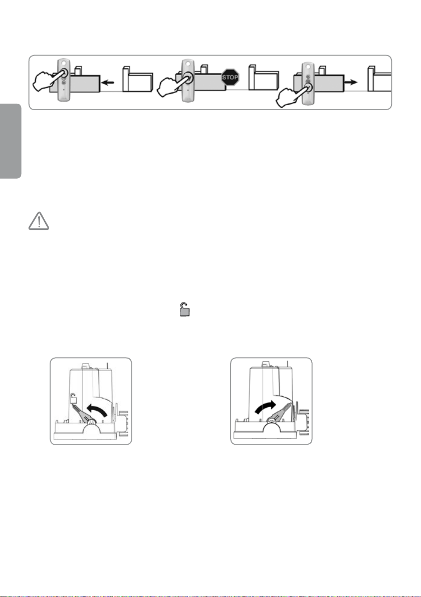
Operation of remote controls or transmitters with 3 push-buttons
Opening by pressing the „Up”
push-button
EN
Note: The remote controls or transmitters with 3 push-buttons do not allow opening the gate
in pedestrian entry mode.
Stopping by pressing the
central push-button
Closing by pressing the
„Down” push-button
Drive unit unlocking / locking
- For safety reasons, carry out these operations after the power supply has
been disconnected because even in the case of power failure, the power supply
could be restored at any moment.
- Always lock the drive before connecting the power supply. The lever must be
in the locked position.
- Never unlock or lock the drive unit when the gate is running (displacement in
electric or manual mode).
When the drive is set in the unlocked position
Then the gate can be moved completely freely. Exercise caution when carrying out this operation.
Unlock the drive
unit by pulling
the lever towards
yourself.
, the gate can be controlled manually in case of power failure.
Lock the drive
unit by pushing
the lever in the
direction of the
gate.
20
Page 21
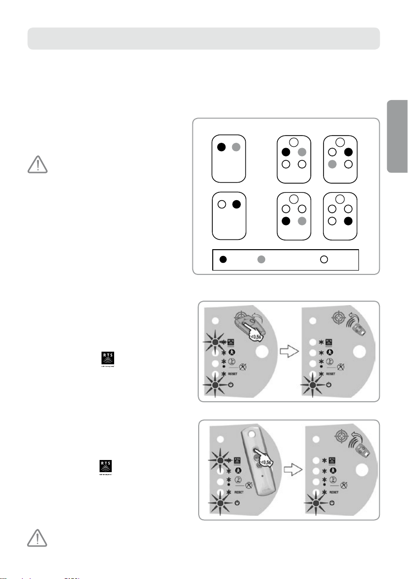
ADVANCED PARAMETER SETTING
2 push-buttons
4 push-buttons
112
2
34
1
2
CODE
3 4
1
2
CODE
34
1
2
CODE
3 4
1
2
CODE
or or
Complete
opening
Opening for pedestrian
entry (if the function
is active)
Unassigned
Note: You cannot set parameters when the gate is running.
Any introduced parameter changes will be taken into account after the rst opening of the gate.
Available push-buttons in remote controls with 2 or 4 push-buttons
Each remote control push-button can be
programmed for control of complete gate opening.
The next push-button allows activation of the function
of opening for pedestrian entry (the function of
opening for pedestrian entry, see page 20).
Push-button 1 cannot be
programmed for the function of
opening for pedestrian entry.
Unassigned push-buttons or an inactive
push-button for opening for pedestrian entry
can be used to control another automatic
mechanism (garage door, shutter, etc.).
Programming of a remote
control with 2 or 4
push-buttons
[1]. Place the remote control on the picture
showing a target.
[2]. Press quickly the remote control push-button
designed for the control of COMPLETE gate
opening.
> RADIO indicator
out when the push-button is released.
The push-button has been programmed.
lights up and then goes
Available combinations of push-buttons for complete
opening / opening for pedestrian entry:
EN
Programming of a remote control with 3 push-buttons
[1]. Place the remote control on the picture showing
a target.
[2]. Press quickly the remote control push-button
Up or Down.
> RADIO indicator
goes out.
The remote control has been programmed.
If 16 remote controls have been programmed, then while programming the 17
remote control, the rst remote control will be deleted, etc.
lights up and then
th
21
Page 22
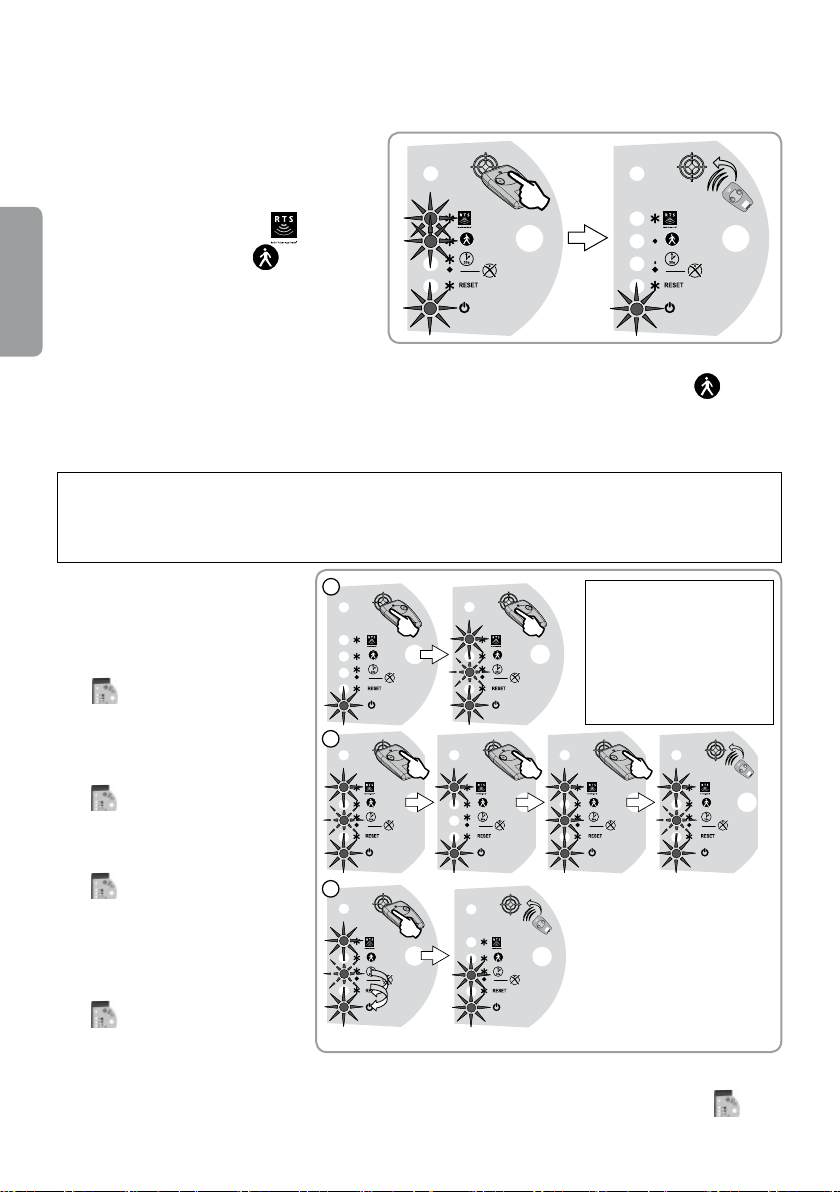
Activation of the function of opening for pedestrian entry
<0,5s
2
3
1
x2
The function of opening for pedestrian entry can be activated using the push-button of the programmed remote
control with 2 or 4 push-buttons (see ‘Available push-buttons in remote controls’, page 19).
[1]. Place the programmed remote control on the
picture showing a target.
[2]. Press quickly the remote control push-button
to be activated.
> The RADIO indicator
PEDESTRIAN indicator
then go out. The function of opening for
EN
pedestrian entry has been activated in this
and the
light up and
push-button.
To switch off the function for opening for pedestrian entry on this push-button, carry out this
function activation procedure (as described below) once again for this push-button. PEDESTRIAN indicator
Activation of the AUTOMATIC CLOSING mode
(recommended in the case of a solar energy supply)
Note: The automatic mode can be activated only when a photocell set has been installed (see description
of conductors on page 23).
Put the remote control on the electronic module to access the settings. In case of a remote control with
3 push-buttons, the settings are not accessible.
[1]. Put the programmed remote
control with 2 or 4 push-buttons
on the picture showing a target.
Press push-button 1 until
AUTOMATIC CLOSING indicator
starts ashing.
[2]. Press push-button 2 until
AUTOMATIC CLOSING indicator
goes out and then lights up and
emits light continuously. Release the
push-button.
> AUTOMATIC CLOSING indicator
starts ashing.
Note: After stage 1 is
nished, successive
stages can be carried out
in remote mode (without
placing the remote
control on the picture
showing a target).
goes out.
[3]. Press remote control push-button
1 twice.
> AUTOMATIC CLOSING indicator
remains lit to signify automatic
22
mode activation.
To switch off automatic closing mode and return to sequential mode, repeat stage 1 described above and
then press quickly remote control push-button 2; pilota, AUTOMATIC CLOSING indicator
out and then start ashing. Press remote control push-button 1 twice.
will go
Page 23
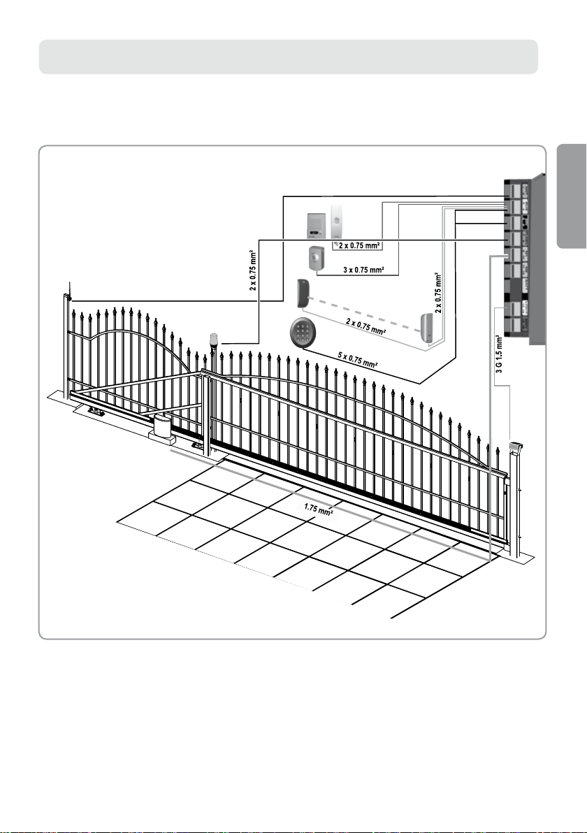
ACCESSORIES
TX
RX
concentric cable
A cross-section of conductors for individual types
of devices
EN
23
Page 24
Photocells------------------------------------------------
2 8 m
25 cm
max. 20 cm
107 mm
43 mm 26 mm
2 x 0.75 mm
2
HO5 RR-F
IP44
1 A
24 Vac/dc
+ 60°C
- 20°C
Ø4
6 mm12 mm
Ø4
Photocells cause the gate to stop and reverse direction during
closing in the case of obstacle detection (photocells obstructed).
Note: If the gate is closed and the photocells are obstructed, the
gate will not open.
EN
► Location of photocells
► Photocell installation and conductors
A set of photocells consists of:
• transmitting photocells (TX),
• receiving photocells (RX).
1 2
5
24
3
4
6
Page 25
TX RX
RX
TX
12
1235
12
TX
7
1235
RX
8
9
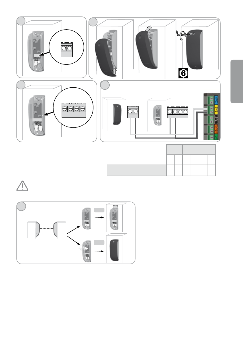
To check that the photocells are set properly, mount the shield of the transmitting
photocell but do not install the shield of the receiving photocell.
11
10
Yellow label (BUS)
11a
11b
TX RX
1 2 1 2 3 5
3 4 3 4 X X
Check proper setting of the photocells:
- If the receiving photocell indicator does not
light up, adjust the position of the photocell
(RX) using a pad. Check once again.
- If the receiving photocell indicator emits
light continuously (proper setting), close
the shield of the receiving photocell (RX).
EN
25
Page 26
► Recognition of photocells by the electronic system of the drive unit
2
3
1
x2
when in sequential mode
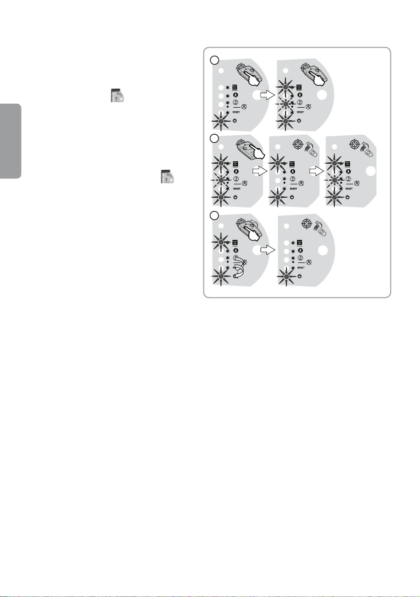
[1]. Put the programmed remote control with 2 or 4 push-
buttons on the picture showing a target. Press remote
control push-button 1 until the AUTOMATIC
CLOSING indicator
starts ashing.
Note: After stage 1 is nished, successive
stages can be carried out in remote mode
(without placing the remote control on the
EN
picture showing a target).
[2]. Press remote control push-button 2 until the
AUTOMATIC CLOSING indicator
out, and then starts ashing.
[3]. Press remote control push-button 1 twice.
Note: In automatic closing mode, the photocells are recognized by the electronic system of the drive unit on
activation of the automatic closing mode (see page 21).
goes out and then
goes
►Removal of photocells
In case of isolation of the photocells:
- in sequential mode: repeat the procedure of recognition of the photocells by the electronic system of the drive
unit in sequential mode,
- in automatic closing mode: repeat the procedure of activation of the automatic closing mode as described on
page 21.
►Obstructed photocells
If the photocells are obstructed during gate closing, the gate will stop and start moving in the reverse direction.
If the gate is closed and the photocells are obstructed, the gate will not open.
►Safety rules
The photocell operation must be checked every 6 months. To do this, shield the photocell with one hand during
gate closing. The gate should stop and open again.
26
Page 27
Orange light-------------------------------------------------------
HO5 RR-F
2x0.75 mm
2
175 m m
60 m m
77 m m
24 VE14
Ø22
10 Watt max
+ 60°C
-20°C
IPX4
24 Vac/ dc
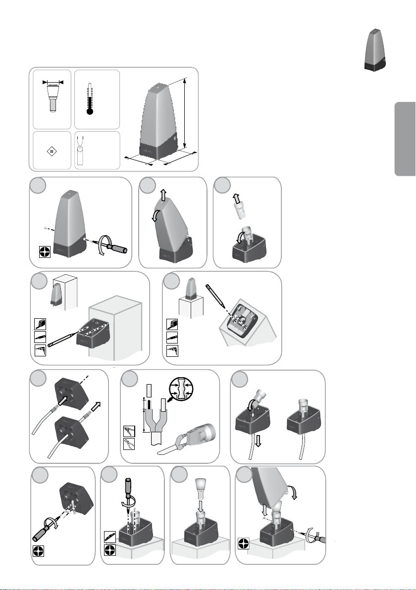
The orange light indicates that the drive unit is running.
It starts ashing 2 seconds before the gate starts moving.
► Installation of orange light
There are two methods available of installing the orange
light (see Fig. 4a and 4b).
EN
1 2
4a
Ø3
5
6
3
4b
Ø3
7
6 mm
12 mm
8
9
10
11
27
Page 28
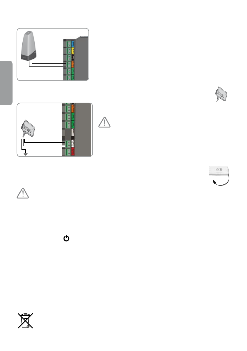
►Conductors of orange light
Connect the orange light to the terminals 7 and 8 (orange label
„FLASH”) of the electronic module.
EN
Zone lighting -----------------------------------------------------
This element is not compatible with a solar
energy supply.
Connect the zone lighting to terminals 13 and 14 (white label
„LIGHT”) of the electronic module.
Emergency battery-------------------------------------------
This element is not compatible with a solar energy supply.
The emergency battery ensures the continuity of gate operation at low speed in case of electrical supply failure.
The battery is built in to the electronic module of the drive and connected with it directly.
To lengthen the amount of time of the battery operation, the wire control systems are disconnected; the gate is
controlled with remote controls and radio transmitters only.
Note: STATUS indicator
ashes (1 pulse) when the drive is supplied by the battery.
►Technical data of the battery
• Operating time: 10 cycles in continuous mode or 24 hours if the gate is in good technical condition.
• Optimum charging time for the battery before use: 48 hours.
• Battery life: 3 years.
To ensure optimum battery life, disconnect the power supply from the gate three times a year and run several
cycles with battery operated drive.
It is necessary to separate batteries and rechargeable batteries from other types of waste and to
transport them to a local waste collection area to be recycled.
28
Page 29
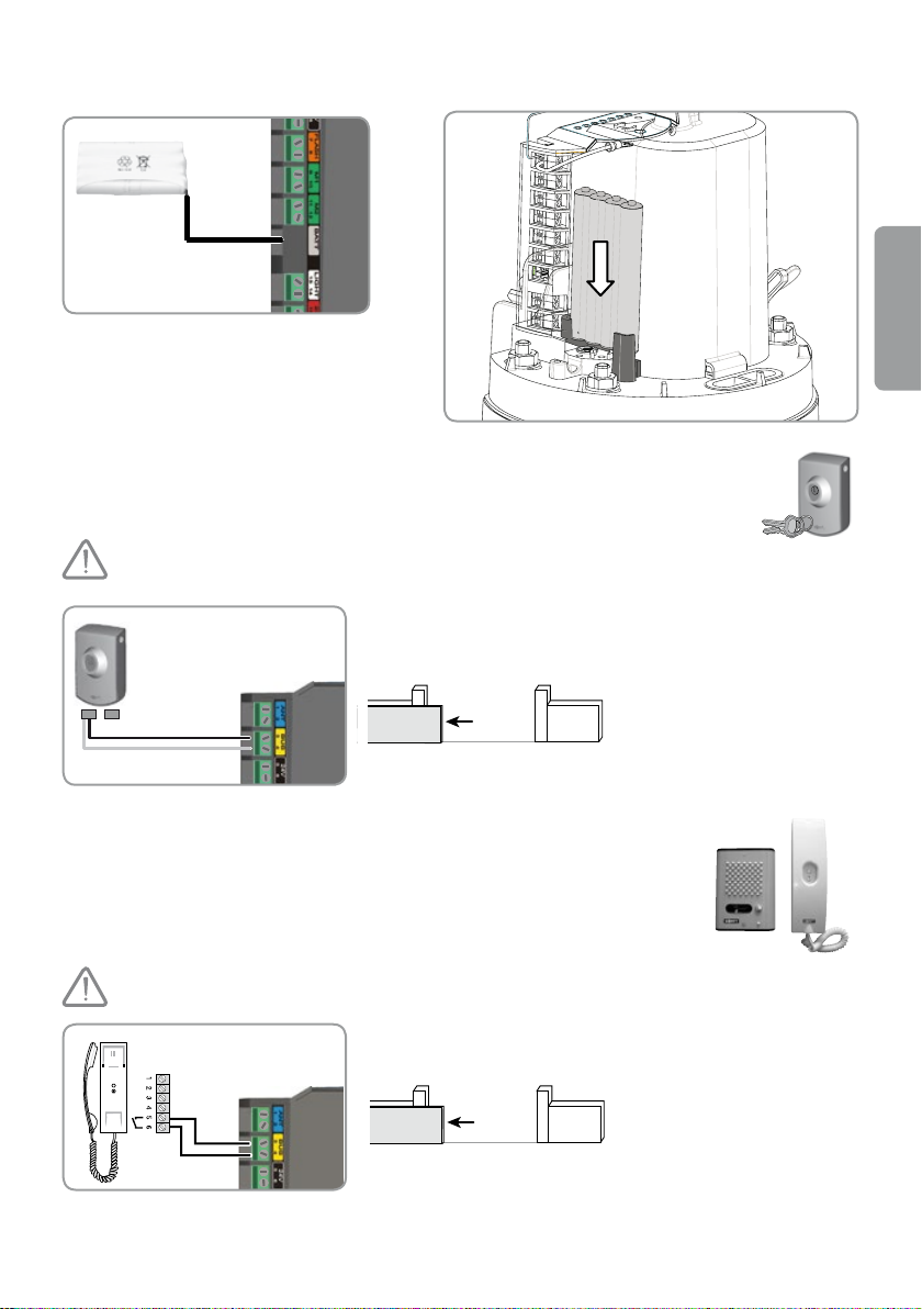
►Battery conductors and installation
Connect the battery to the electronic
module terminal provided for this purpose
(grey label „BATT”).
Key switch-----------------------------------------------------
This element is not compatible with a solar energy supply.
Connect the key switch to the electronic module terminals 3 and 4
(yellow label „BUS”).
Interphone------------------------------------------------
EN
This element is not compatible with a solar energy supply.
Connect the interphone to the electronic module terminals
3 and 4 (yellow label „BUS”).
Note: In the case of the connection of an interphone of a different type
to the one presented above, check to see if it is equipped with an
output contact without power supply.
29
Page 30
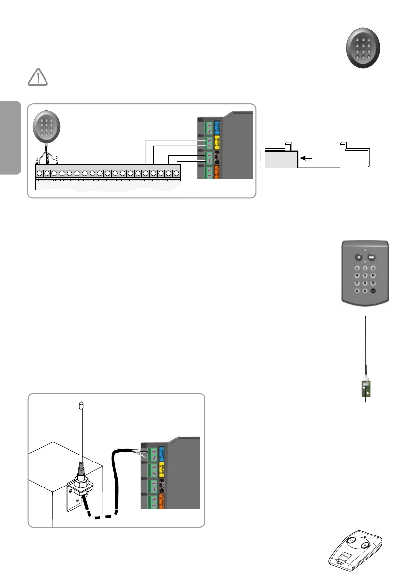
Panel with digital code--------------------------------------
T1 C1 R1 VR3 T2 C2 R2
T3 C3
H P2 MP1
+HE –V
This element is not compatible with a solar energy supply.
EN
Connect:
• T1 and C1 of the panel with a digital code to the electronic module terminals 3 and 4 (yellow label „BUS”).
• V and V of the panel with digital code to the electronic module terminals 5 and 6 (black label „24 V”).
Radio panel with code ------------------------------------
Independent antenna-------------------------------------------
An independent antenna with a longer range can
replace the wire antenna.
Place it on the post top and check to see if it is
exposed.
Connect the antenna to the electronic module
terminals 1 and 2 (blue label „ANT”):
• conductor core to terminal 1
• stranded aerial wire to terminal 2
Remote control with 2 push-buttons----------------------------------------
30
Page 31
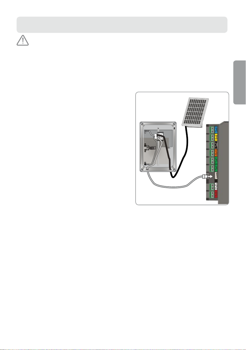
SOLAR ENERGY SUPPLY
+-
1
2
3
Never connect the drive unit to a power supply of 230 V when it is already
connected to a solar energy source because this can lead to damage to the
electronic module of the drive.
When the drive unit operates using a solar energy supply:
- the gate can be controlled by means of remote controls and radio transmitters only (wire control is inactive),
- protecting wire accessories (photocells, the orange light) are still active.
►Connection to a solar energy source
Connect the lead-in wire from a solar battery
to the grey terminal „BATT” of the electronic module
of the drive.
Note: When the drive is supplied with a solar energy
source, the wire control systems are disconnected; the
gate is controlled by means of remote controls and radio
transmitters only.
►Advice concerning use
To reduce energy consumption by the gate drive unit,
we recommend the following:
- the gate should stay closed to ensure a longer period
for battery recharging,
- the gate should not remain open for longer than 2 days,
- switch on automatic closing mode of the system
(see page 21).
EN
31
Page 32
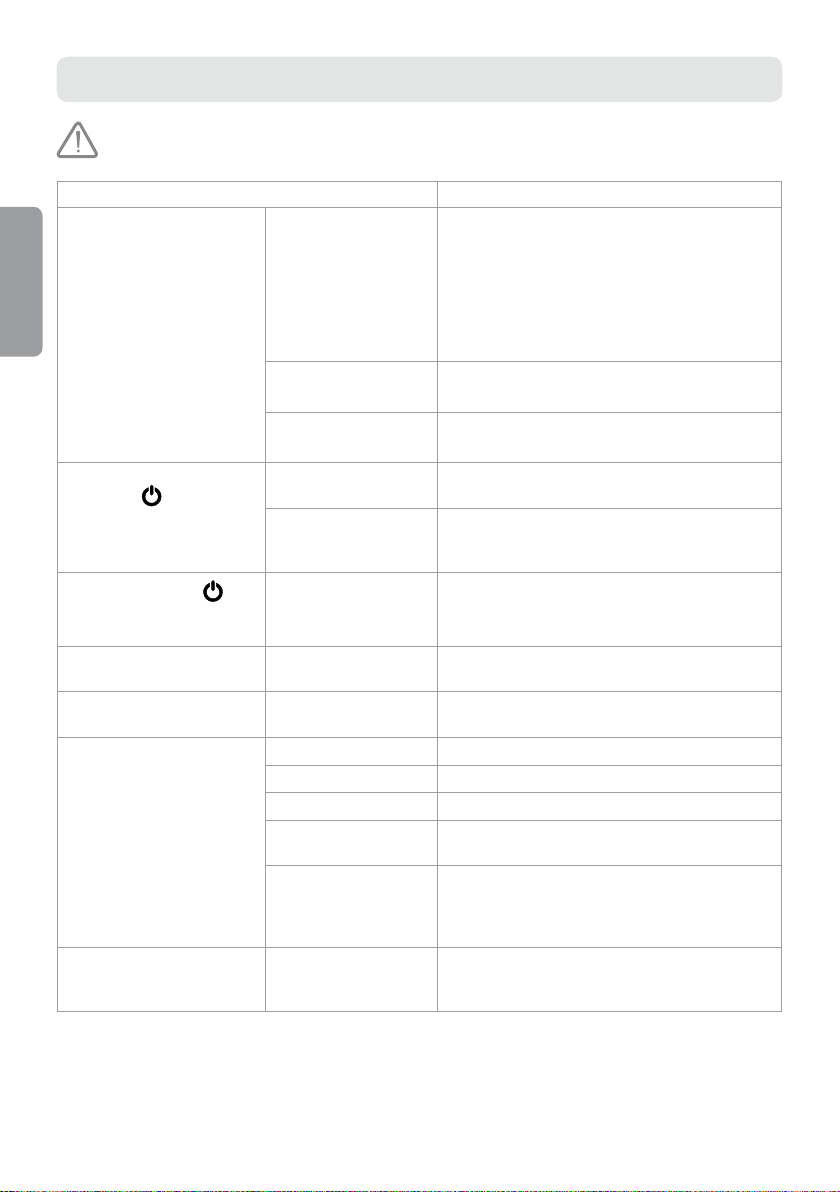
TROUBLESHOOTING
Switch off the power supply of the system during cleaning or any other
maintenance activities.
DIAGNOSTICS FAULT CLEARING
The drive does not
respond to commands
from the remote control
EN
Limited operating range
of the remote control.
Unprogrammed remote
control.
Unlocked drive. Lock the drive.
- Check the battery of the remote control (see
„Replacement of the remote control battery” on the
next page).
- Check the electronic module antenna (conductors,
position – see the next page).
- Check possible source of radio frequency interferences
(overhead line pole, reinforced brickwork, etc.).
If this is the case, t an external antenna.
Program the remote control (see page 20).
STATUS indicator
(STATUS)
electronic module does
not emit any light
STATUS indicator
of the electronic module
is ashing:
1 pulse Working mode with the
2 pulse The drive unit is awaiting
3 pulse Photocell failure:
4 pulse Short circuit at the output
of the
No power supply for
the drive unit.
Very low light intensity
outdoor = the drive unit
is in standby mode.
emergency battery supply.
the gate path teaching.
- Obstructed photocells. Remove any obstacles that are obstructing the photocells.
- Photocells set improperly. Correct the photocell setting (see page 24).
- Photocell conductors
connected improperly.
- No photocells /disconnected
photocells.
BUS (terminals 3-4) of the
electronic module.
- Check the mains supply.
- Check the supply conductor.
To carry out settings, increase illumination outside the
electronic module (eg. using a torch).
Check the mains supply.
Restart the gate path teaching (see page 15).
Connect photocell conductors in accordance with the
instructions given on page 24.
- Check if the photocells are connected properly.
- If photocells are disconnected intentionally and the
gate is working in automatic closing mode, switch
off automatic closing mode (see page 21).
Check accessories connected to the output BUS
of the electronic module.
32
Page 33
DIAGNOSTICS FAULT CLEARING
1
2
5 pulses Thermal protection of the
6 pulses Short circuit at the output
The automatic closing
mode does not start
(the AUTOMATIC
CLOSING indicator
remains unlit).
drive is switched on.
24 V (terminals 5-6) of the
electronic module.
Short circuit within the
orange light (terminals
7-8) of the electronic
module.
Short circuit within
the drive unit.
Photocells have not been
installed.
Wait for the drive to cool down until the STATUS
indicator
Check the device connected to the output 24 V of the
electronic module.
Check conductors of the orange light (see page 27).
Check the conductors of the drive unit (see page 13).
Install photocells (see pages 23 and 24).
starts emitting light continuously.
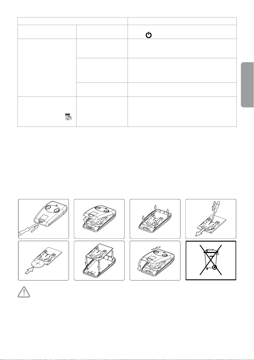
►Replacement of the remote control battery
The battery life is usually 2 years.
EN
WARNING: Observe the polarity (+/-) of the batteries; they must not be recharged or thrown into re or water. They must not be
exposed to high temperatures. Used batteries must not be opened or mixed with batteries of another type or used batteries (this can
result in an explosion, electrolyte leakages and damage of different types). Keep out of the reach of children.
Li
33
Page 34
3
2
1
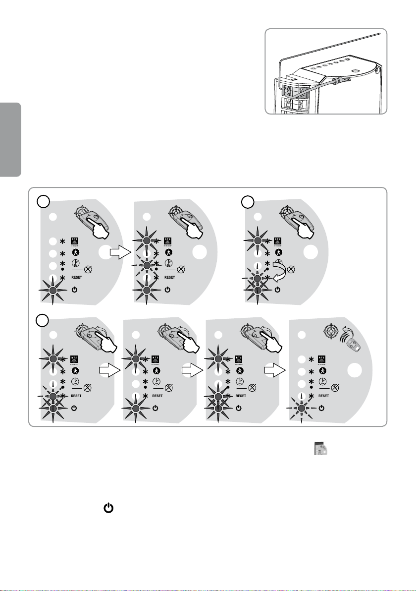
Antenna
►Antenna conductors and position
The antenna must be connected to terminal 1 of the electronic system
of the drive unit and positioned as shown in the picture on the right.
►Removal of settings
The following settings can be removed: the gate path and activation
of the automatic gate closing mode.
EN
When are the settings to be removed?
After the gate path teaching, in the case of modication of the drive conductors.
In the case of detection of an unexpected obstacle as a consequence of normal wear of the gate.
[1]. Put the programmed remote control with 2 or 4 push-buttons on the picture showing a target.
Press the remote control push-button 1 until the AUTOMATIC CLOSING indicator starts
[2]. Press remote control push-button 1 once.
> MEMORY RESET indicator (RESET) is ashing.
[3]. Press remote control push-button 2 and hold it until the MEMORY RESET indicator (RESET) lights up.
Release push-button 2.
> STATUS indicator
34
is ashing.
ashing.
Page 35
3
2
1
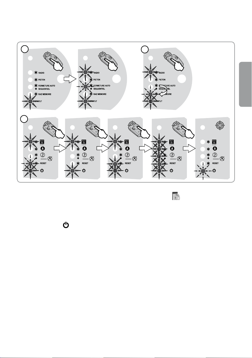
►Removal of programmed settings and remote controls
The following settings can be removed: the gate path, activation of the automatic gate closing mode
and all programmed remote controls or radio transmitters.
[1]. Put the programmed remote control with 2 or 4 push-buttons on the picture showing a target.
Press remote control push-button 1 until the AUTOMATIC CLOSING indicator
[2]. Press remote control push-button 1 once.
> MEMORY RESET indicator (RESET) is ashing.
[3]. Press remote control push-button 2 until all indicators light up. Release push-button 2.
> STATUS indicator
is ashing.
starts ashing.
EN
35
Page 36

Oziemkówka 57A
08-420 Miastków Kościelny, Polska
Tel. 48 25 683 05 55, fax: +48 25 683 78 38
e-mail: [email protected]
www.polargos.eu
 Loading...