

Polar Furnace G2-PLUS, G2, G3 Owner's Manual
Heater Setup
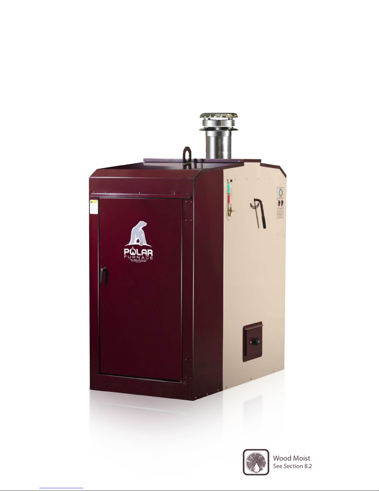
Owner’s Manual for G2, G2-Plus & G3
G-Class
Outdoor Wood Furnace
1
Wood Moisture Requirements
See Section 8.2 of this Manual
1

Polar Furnace Mfg. Inc. | 9086 RD31 NW | Sperling | MB | R0G 2M0 | www.polarfurnace.com
The G-Class indoor/outdoor hydronic heater by Polar Furnace is listed by Intertek to the applicable portions of the following
standard: ASTM E 2618-10 and/or EPA Method 28 WHH or EPA Method 28 WHH-15 and ASTM E2515-2011. The
G-Class G2-Plus indoor/outdoor hydronic heater by Polar Furnace is also listed by Intertek to the applicable portions of the
following standard: CSA B415.1-10. The G-Class indoor/outdoor hydronic heater by Polar Furnace is listed by CSA group
to the applicable portions of the following standards: UL 2523 Standard for Solid Fuel-Fired Hydronic Heating Appliances,
Water Heaters and Boilers and CAN/CSA-B366.1-11 Solid-Fuel-Fired Central Heating Appliance. The G-Class is CSA and
UL certified for indoor or outdoor installation. Indoor installations must satisfy CSA CAN/CSA-B365 installation code for
solid fuel burning appliances as well as any other applicable standards or regulations. The G-Class includes one 2-foot stainless
steel insulated chimney section. Use only stainless steel solid fuel chimneys specified by Polar Furnace to extend the chimney.
To obtain a French translation of this manual, please contact your dealer or visit www.polarfurnace.com.
(Pour obtenir une traduction française de ce manuel, s’il vous plaît contacter votre revendeur ou visitez www.polarfurnace.com.)
Specifications
8-Hour Output Rating Btu/hr 66 897 108 982 142 533
8-Hour Average Efficiency
Manufacturer’s Rated Heat
Output Capacity
Output Range Btu/hr 0 to 160 000 0 to 180 000 0 to 200 000
Annual Efficiency Rating
1
Specifications subject to change without notice
*This heater is U.S. ENVIRONMENTAL PROTECTION AGENCY certified to comply with 2015 particulate emission
standards. Not approved for sale after May 15, 2020. Under specific test conditions, this heater has been shown to deliver heat
at rates shown for the respective model above.
**This heater is U.S. ENVIRONMENTAL PROTECTION AGENCY Certified to comply with 2020 particulate emission
standards using cord fuel. Under specific test conditions, this heater has been shown to deliver heat at rates shown for the
respective model above.
Performance is a product of the combustion rate, combustion efficiency and heat exchange efficiency of a single fuel load. Results
may vary because of many additional factors including wood species, wood quality, wood quantity and moisture content of the
wood used. Efficiencies are determined under the same test conditions using higher heating value, lower heating value and
annual fuel utilization efficiency (AFUE). This wood heater has a manufacturer-set minimum low burn rate that must not be
altered. It is against federal regulations to alter this setting or otherwise operate this wood heater in a manner inconsistent with
operating instructions in this manual.
1
U of M G2* G2-Plus** G3*
lower/higher
heating value (%)
Btu/hr 160 000 180 000 200 000
lower/higher
heating value (%)
76.5/71.2 87.2/81 80.5/74.8
71.6/66.5 78.7/73.1 77.9/72.3
DO NOT OVERFIRE THIS HEATER. Attempts to achieve heat output rates that exceed heater design specifications can
result in permanent damage to the heater. Any person(s) operating a hydronic heater must comply with all applicable laws,
including but not limited to local ordinances. Improper use or failure to maintain the hydronic heater may cause nuisance
conditions. The person(s) operating a hydronic heater is/are responsible for operation in a manner that does not create a
nuisance condition. Meeting the setback distance and stack height recommendations from the manufacturer and requirements
in applicable State and local regulations may not always be adequate to prevent nuisance conditions in some areas due to
terrain or other factors. Operating and maintaining an outdoor furnace may not be suitable to every individuals’ abilities or
lifestyles. Be sure to review the Owner’s Manual for the appliance with your dealer prior to purchasing or operating this heater.
IMPORTANT: Read and fully understand this manual prior to installing and/or operating
a Polar Furnace heater. This wood heater needs periodic inspection and repair for proper
operation. It is against federal regulations to operate this wood heater in a manner
inconsistent with operating instructions in this manual.
2
Owner’s manual for Polar Furnace models: G-2 & G-3

POLAR FURNACE G-CLASS HEATER WARRANTY (v. 15-1)
The longevity of your G-Class heater will depend on how well the heater is maintained and if the wood
burned in the unit meets the wood moisture requirements specified in the owner’s manual. With proper
operation, proper maintenance and proper wood quality your new furnace will last a long time. Be sure
to understand and follow the operational and maintenance instructions included in the owner’s manual.
Polar Furnace Mfg. Inc. (The Company) warrants the water jacket and fire chamber of the heater identified herein
to be free from leaks during normal use for a period of 4 (four) years from the date of original purchase to the original
purchaser of this heater. From year 1 (one) through year 4 (four) The Company will cover the cost of repairing any
leaks in the fire chamber and water jacket onsite or at our factories including materials, parts, travel, shipping and labor.
Electric and electronic components as well as high temperature refractory and the heater housing are limited to
a 12 month 100% replacement warranty including parts, shipping, travel and labor. Only the manufacturer at
the address on this certificate will determine, in its sole and absolute discretion, all warranty issues. Any repair
work claimed under warranty must be approved in writing by The Company prior to any repairs being started.
If repair is not feasible for any reason as judged by The Company, our obligations under this warranty are limited
to providing a replacement heater per the following schedule. For the 15 year warranty period the following prorated replacement charge will apply.
Schedule of Charges for Replacement of the Complete Heater.
From 1 through 2 years Company’s then current list price less 100%
From 3 through 4 years Company’s then current list price less 100%
From 5 through 6 years Company’s then current list price less 60%
From 7 through 10 years Company’s then current list price less 25%
From 11 through to 15 years Company’s then current list price less 10%
All replacement heaters are FOB our factory unless otherwise specified in this warranty.
The warranty period on any replacement heater is from the date of the sale of the original heater.
General Conditions of this Warranty.
The warranty registration form, delivery checklist, and customer acceptance must be completely filled in and
signed by the customer and dealer and submitted to The Company for this warranty to be valid. The warranty
contained herein shall be voided if the heater is not installed, operated and maintained as instructed in the owner
manual. Using wood that does not meet the wood moisture requirements detailed in the owner’s manual voids
this warranty. The heater must never be pressurized; pressurizing the heater voids this warranty. The boiler
protection valve must be maintained as described in the owner’s manual and failure to properly maintain the
boiler protection valve voids this warranty. A properly qualified tradesperson/s should supervise or perform all
installations. If the chimney needs be extended an appropriately certified and approved insulated chimney system
must be used. The insulated chimney is not covered under this warranty. This warranty is void if the chimney
3

installation does not meet all of the installation requirements detailed in the owner’s manual. Your dealer may
charge you for a service call to do warranty work. Parts will be replaced on an even exchange basis. Polar Furnace
heaters are not intended to be the only source of heat. A backup system should be in place to prevent resultant
damage due to a lack of heat. This warranty is limited to defective parts repair and/or replacement only and
excludes any incidental and consequential damages. Door seals, door insulation, light bulbs, fire tending tools,
heat shields, Strong Wall liner, hearth plates and any other wear items are not covered under this warranty.
High temperature refractory materials are warranted for 1 year under this warranty. In use, small cracks can
occur in high temperature refractory and will not affect the performance of the heater. Damage caused by abuse,
accidents, improper use, improper installation, excess creosote buildup, overheating, freezing, corrosion, negligence,
accidents in transit, and pressurization are not covered under this warranty. Damage resulting from modifications
or alterations will not be covered under this warranty. If the serial number on the equipment is defaced, altered or
removed this warranty is void. Damage caused by burning flammable materials (such as petroleum products) or
any other material besides properly prepared wood will void this warranty. Only nontoxic antifreeze that meets
and/or is approved per all applicable regulations and standards may be used. The Company will not be responsible
for any environmental damages or charges resulting from use of toxic and or unapproved types of antifreeze.
Antifreeze will breakdown over a period of time and therefore should be tested annually to ensure adequate freeze
protection. Always dispose of antifreeze per federal, state, provincial, local or any applicable laws and regulations.
Loss of antifreeze under any situation and condition is not covered under this warranty. The Company is not
responsible for replacement of water, water treatment, antifreeze, removal, disposal, costs of transportation, or
shipping charges unless otherwise specified in this warranty. Warranty does not cover any plumbing components,
boiler piping, valves, controls or any other component or system external to the boiler package. WARNING,
The Company will not warranty the inside of the fire box due to ash corrosion. Rotation of ashes and/or removal
of ashes from the fire chamber must be performed as per the operator manual instructions. WARNING, The
Company will not warranty the water jacket due to corrosion from corrosive or improperly treated water. An
appropriate water treatment must be added and maintained and receipt retained for proof of use to establish
any warranty claims. We will not be liable to any contingency beyond our control including war, strikes, floods,
government restrictions or short supply of material. We will not be liable for any labor cost, except above schedule.
This warranty replaces and supersedes any and all other warranties, expressed or implied, directly and or indirectly
whether at law, common law, equity and/or statute and constitutes the only warranty of The Company and the
only liability of The Company. This warranty constitutes the entire agreement between the parties with respect
to the subject matter and supersedes all prior agreements, negotiations, discussions, undertakings, representations,
warranties and understandings, whether written or verbal. This Warranty is governed by, and is to be construed and
interpreted in accordance with the laws of Manitoba and the federal laws of Canada applicable in Manitoba. The
purchaser and The Company each irrevocably agree to submit to the jurisdiction of the courts of Manitoba. The
Company’s limitation of liability pursuant to any warranty shall be equivalent in all respects to the sum of $1.00.
Polar Furnace Mfg. Inc.
Box 159. Sperling, Manitoba. R0G 2M0
PH: 1-204-626-3485 FAX: 1-204-626-3326
NOTICE: To activate this warranty, the white copy of the warranty activation form (page 5) as well as a copy
of the original bill of sale (invoice) must be mailed to the Polar Furnace address above within thirty (30) days of
furnace delivery to end user.
4
Owner’s manual for Polar Furnace models: G-2 & G-3

POLAR FURNACE MFG. INC.
WARRANTY (v.15-1) ACTIVATION1 FORM—DOWN DRAFT HEATER
WARRANTY REGISTRATION FORM
Customer’s Name:____________________________ Dealership Name: ___________________________
Address:____________________________________ Address: __________________________________
City, State/Prov. Code:_________________________ City, State/Prov. Code:_______________________
Phone: (____)________________________________
Serial No.___________________________________ Date of Purchase: ____________/_______/_______
DELIVERY CHECKLIST
_____ Review owner’s manual.
_____ Identify safety hazards & demonstrate proper
operation.
_____ Review warranty and service requirements.
_____ Explain requirement that properly seasoned wood
_____ Explain required maintenance schedule.
_____ Review and explain Boiler Protection Valve
Maintenance (Manual Section 14.4)
must be used. (review manual section 8.2)
_____ No warranties are validated unless this form and
registration are completed and returned.
CUSTOMER ACCEPTANCE
I have inspected the Polar Furnace heater with the customer and reviewed all items on the delivery checklist.
I have thoroughly instructed the customer on the equipment identified herein and thoroughly reviewed the
operator’s manual. The customer has accepted responsibility for the operation and maintenance of the product
identified herein.
Date: ________________________________ Dealer’s Rep. Signature: ___________________________
The dealer rep. and I have inspected my new Polar Furnace heater and reviewed all items on the delivery checklist.
The dealer rep. has reviewed the operator’s manual with me and has thoroughly instructed me on the equipment
herein. I assume full responsibility for the operation and maintenance of the product identified herein.
Date: ________________________________ Owner’s Signature: ______________________________
A nominal fee may be charged for service calls. All sales are final. Heater approved for use with well-seasoned
wood only. Suitability of use is the customer’s decision. The customer is responsible for ensuring conformance to
local bylaws and regulations. A backup heating system is strongly recommended.
White—Polar Furnace copy Yellow—Dealer copy Pink—Customer copy
1
To activate this warranty, the white copy of this warranty registration form as well as a copy of the original bill of sale (invoice) must be mailed to
Polar Furnace Mfg. Inc., Box 159, Sperling MB, R0G 2M0 within 30 days of delivery of furnace to end user.
5


Table of Contents
A. Warranty Details 3
B. Warranty Activation Form 5
C. Table of Contents 7
1. Introduction 8
2. Warnings & Cautions 9
3. Responsible Ownership 11
4. Heater Components 12
5. Safety 13
6. Heater Setup 14
7. Heater Controls 21
8. Operating the Heater 24
9. Maintaining the Heater 30
10. Water Testing & Treatment 36
11. Heater Model Specifications 37
12. Electrical Diagrams 38
13. G-Class Parts 39
14. Plumbing 45
For service and support on your Polar Furnace contact your local dealer
7

1
Introduction
The Polar Furnace G-Class Heaters are wood-fired,
downdraft, hydronic heaters. The downdraft burning
design allows for controlled combustion of wood
which results in far lower smoke and particulate
emissions and higher efficiency when compared to
other designs.
1.1 !! NOTICE !!
The Warranty Activation form is located on page 5.
This form must be thoroughly completed and the
white copy returned to Polar Furnace Mfg. Inc. to
ensure product support and warranty activation.
G-Class heaters are tested and approved by CSA
INTERNATIONAL to
CSA/CSA-366.1-M91 and UL2523
G-Class heaters are tested to EPA test Method 28
WHH and are EPA Phase II qualified.
1.2 Product Feature Variation
Our commitment is to provide you with the best
possible wood burning technology. As part of this
commitment, we make improvements to our products
on a regular basis as we strive to make them even
better. Although a concerted effort is made to keep
this manual as up-to-date regarding any changes to
our products, there may be noticeable differences. If
clarification of any part of this manual is needed, don’t
hesitate to contact your local Polar Furnace dealer or
contact Polar Furnace directly.
1.3 Save These Instructions!
Keep this manual for as long as you own the
Polar Furnace heater. Read and understand these
instructions before installing or operating this heater.
8
Owner’s manual for Polar Furnace models: G-2 & G-3

Warnings & Cautions
2.1 !!WARNING!!
A person operating a hydronic heater must comply
with all applicable laws or other requirements such
as state or provincial laws or regulations and local
ordinances.
2
The manufacturer does not recommend burning
treated or contaminated wood (i.e. railroad ties or
pressure treated lumber).
2.2 !!WARNING!!
All installations and operations must follow the
applicable federal, provincial, state, and local codes
for wiring, plumbing, chimney installation, chimney
extension (if required) and firing of this unit. When
the relevant local codes differ from this manual, the
local codes take precedence.
2.3 !!WARNING!!
Strictly maintain the following clearances around the
heater to any combustibles including fuel storage.
Front—24”, Right—6”, Left—1”, Rear—6”, Top—2”,
Flue—6”.
2.4 !!WARNING!!
This heater is designed to burn natural wood only.
Higher efficiencies and lower emissions generally
result when burning air-dried seasoned hardwoods
as compared to softwoods or to green or freshly
cut hardwoods. DO NOT BURN: unclean wood,
unseasoned wood, garbage, tires, lawn clippings,
leaves, brush trimmings or general yard waste,
materials containing asbestos, materials containing
lead, mercury or other heavy toxic metals, materials
containing plastic, waste petroleum products, paints
and paint thinners, asphalt products, chemicals, coal,
glossy or colored paper, construction and demolition
debris, plywood, particleboard, salt water driftwood
and other salt water saturated materials, manure, or
animal carcasses. Burning these materials may lead
to the release of toxic fumes or render the heater
ineffective and cause smoke. Burning these materials
can cause irreparable damage to your heater which is
not covered under warranty.
2.5 !!WARNING!!
Burn wood only! Dry seasoned wood is preferable.
2.6 !!WARNING!!
All Polar Furnace heaters operate at atmospheric
pressure. DO NOT, in any way, obstruct, block or plug
the overflow/fill pipe located on top of the heater. DO
NOT install a pressure relief valve. This boiler should
not be connected to an existing heating system unless
a water to water or water to air heat exchanger is used.
2.7 !!WARNING!!
Use of a rain cap with an approved spark arrestor is
required.
2.8 !!WARNING!!
Most Polar Furnace heaters are installed outdoors. All
fire clearances on page 15 should be observed. Always
keep area around and in front of fire door cleared from
combustible materials. DO NOT store fuel within
clearances listed on label.
2.9 !!WARNING!!
Polar Furnace heaters are CSA certified for outdoors
and indoors. When used indoors, special care must
be taken to ensure the installation conforms to
local installation requirements. Plan for makeup
air, ventilation of smoke when opening door,
chimney clearances and heights, and clearances from
combustibles. Consult local professionals. Field
installations must satisfy CSA CAN/CSA-B365
installation code for solid fuel burning appliances as
well as any other applicable standards or regulations.
If extended chimney height is needed, use an insulated
chimney system.
2.10 !!WARNING!!
Installation should be completed by appropriately
qualified personnel.
For service and support on your Polar Furnace contact your local dealer
9

SECTION 2: WARNINGS & CAUTIONS
2.11 !!WARNING!!
Never let small children play near or tamper with the
heater. Only responsible adults should operate the
heater. Outer surfaces may be hot during operation.
Ensure children do not touch heater.
2.12 !!WARNING!!
Always open the load door slowly while standing well
back and behind the door. Open the outer door and
wait one minute before opening inner doors. Do not
look directly into the fire chamber until at least 60
seconds after opening the load door. Failure to do so
may result in serious injury from flashbacks.
2.13 !!WARNING!!
Keep fuel door tightly closed during operation.
2.14 !!WARNING!!
In case of a runaway fire, disconnect the heater from
the electrical supply and ensure all doors are closed.
Check to ensure the air supply gates are not stuck
open. Check aquastat settings. Add water to ensure
that the heater is not low on water.
2.16 !!WARNING!!
Be concerned about ground water and insulate
the distribution pipes to avoid excessive wood
consumption.
2.17 !!WARNING!!
The secondary combustion chamber, heat exchanger
and areas above and below the heat exchanger should
be cleaned regularly to remove accumulated creosote
and ash.
2.18 !!WARNING!!
Cleaning the firebox, flue pipes, chimney, heat
exchanger and fan is especially important at the end
of the heating season to minimize corrosion. All
accumulated ash MUST be removed.
2.19 !!WARNING!!
Care should be taken to avoid potential smoke
problems. Downdraft heaters can smoke if not
operated as per recommendations or without properly
prepared wood. Be a responsible neighbor and use
properly seasoned firewood. Use a chimney extension
if required.
2.15 !!WARNING!!
DO NOT operate heater unless the water level gauge
shows that the water jacket is in the “Full” range.
2.20 !!Alert: Monitoring Smoke and Carbon Monoxide!!
During the combustion process, the presence of smoke is a strong indicator that the fuel is not being
consumed efficiently. Smoke is created when the combustion air supply to the fuel load is inadequate to
burn all the gases and particulate being released as the wood is consumed. This is why it is important to
establish the correct draft with the furnace/chimney system. One of the byproducts of poor combustion
is carbon monoxide, a colourless, odourless, and tasteless gas that is toxic when inhaled and which can
be fatal depending on concentration levels and exposure time. Note that although carbon monoxide is
produced during poor combustion that might also create smoke (as described above), high levels of carbon
monoxide may be produced in the absence of smoke. For example, this could take place when a wood fire
has been reduced to the coal state and the draft starts to reduce as less heat is available to keep the chimney
warm. Some level of carbon monoxide is being generated in all stages of the combustion process regardless
of the fuel.
Continued on next page....
10
Owner’s manual for Polar Furnace models: G-2 & G-3
Owner’s manual for Polar Furnace models: G-2 & G-3

Several precautions must be taken to minimize the risk of carbon monoxide poisoning especially when the
G-Class is installed in a building:
• First, run the furnace in the most efficient manner possible to reduce the production of carbon monoxide.
Use well seasoned, dry wood and establish the correct operating draft as laid out in these operating instructions
to help limit CO emissions.
• Second, Building Pressure—if the combustion air for an appliance (i.e., the wood furnace) comes from
within the same building in which the appliance is located, there will be a tendency for the internal building
pressure to become negative. Adequate mechanical ventilation must be supplied to the building to neutralize
the building pressure, otherwise there is a risk of reversing the flow of exhaust flue products back into the
building. These flue products may not only come from the wood furnace but also from other combustion
appliances in the building.
• Thirdly, Smoke Alarms and Carbon Monoxide Detectors—Smoke alarms and carbon monoxide detectors
are not only important tools for protecting the inhabitants of a building, but they are mandated in many
jurisdictions. Although these items should be located on every level of a building there are two locations
that are of prime importance. The first is in the sleeping areas of the building, and the second is in the
location where the combustion process is taking place. Check with local codes for details on alarm/detector
requirements. Carefully follow installation instructions included with the purchase of your Smoke Alarm and
Carbon Monoxide Detector(s).
Responsible Ownership
3.1 Safety First!
• Be safety conscious.
• Clear ground around heater.
• Use non-combustible cement blocks, patio blocks
or cement base under heater.
• Install the rain cap on the chimney. Use an
approved spark arrestor.
• Use a good quality pipe for hot water distribution.
• ALWAYS HIRE APPROPRIATELY QUALIFIED
INSTALLERS!
3
3.2 Minimize Smoke Emissions.
Burn Wisely.
• Be considerate of your neighbours when operating
your furnace. If you use your furnace in the summer
months, ensure that your chimney exhaust is not
adversely affecting any neighbours with open
windows.
• Consider prevailing wind direction when choosing
a site location for the heater.
• Water can be piped a long distance with minimal
heat loss. This is a good option to avoid smoke
related problems.
• Don’t burn garbage. Burn only well-seasoned
firewood.
11

4
Heater Components
Diagram 4.1–Heater Components
Item # Description
1 Heat Exchanger Access Cover
2 Chimney Hookup
3 Waterjacket Temperature Gauge (On some models, check inside Main Outer Door)
4 Furnace ON/OFF Switch, Work Light ON/OFF Switch
5 Water Level Sight Gauge
6 Heat Exchanger Cleaning Actuator Lever (Easy Sweep)
7 Heat Exchanger Bottom Cleanout
8 Rear Bottom Access Panel—Plumbing Hookup, Air Damper Setting
9 Work Light (inside outer door)
10 Rear Top Access Panel—Suction Fan Access, Electrical Access
11 Overflow/Fill Pipe
12 Lifting Hook
13 Main Outer Door
14 Loading Door
15 Ignition Door
16 Front Bottom Cleanout Door
12
Owner’s manual for Polar Furnace models: G-2 & G-3
Owner’s manual for Polar Furnace models: G-2 & G-3

5.1 !! WARNING !!
Maintain minimum distances between heater and
combustibles. (Refer to section 6.6)
5.2 !! WARNING!!
Develop and implement a clearly formulated plan of
what to do in the event of a chimney fire.
5.3 !! WARNING!!
Keep area around heater clear of combustibles.
5.4 Flashbacks
5.4.1 !! CAUTION !!
ALWAYS KEEP BODY AND FACE WELL
AWAY FROM LOAD DOOR, ACCESS
DOORS AND CLEANOUT DOORS WHILE
OPENING THEM. FAILURE TO DO SO CAN
RESULT IN SERIOUS BODILY INJURY FROM
FLASHBACKS.
When opening any access panels on the heater there
is danger of flashbacks. It is important to understand
what causes flashbacks before operating the heater.
Read the following explanations carefully and be sure
to understand what flashbacks are before attempting
to operate the heater.
Safety
5
5.5 The Combustion Fans Have
Just Shut Off
Once the heater reaches the point where the water
temperature is high enough, the controller shuts off
the combustion fans. When the fans stop blowing,
actuators also close off the air supply openings. This
stops any new air and oxygen from getting into the
fire chamber. At this point the fire chamber is still
extremely hot. The heat in the fire chamber continues
to bake the wood which continues to break down into
combustible smoke and gases. Without oxygen, these
combustible, hot gases do not burn off but accumulate
in the fire chamber. When a door is opened, fresh air
and oxygen mix with the hot combustible gases which
then ignite and explode. Always keep face and body
well away when opening the load door, ignition door,
bottom and side cleanout doors.
5.6 Hot Surfaces
Some surfaces on the boiler get hot. Always wear
protective leather gloves when working on or
around the heater, when loading the heater or when
performing maintenance on the heater.
5.4.2 Cause of Flashbacks
The root cause of flashbacks is the accumulation of
oxygen-starved hot gases inside the fire chamber.
These gases cannot combust without oxygen. Opening
the load door allows fresh air and oxygen to mix with
the hot gases causing them to ignite and explode.
5.4.3 Conditions Causing Flashbacks
There are some combustion conditions that greatly
increase the risk of flashbacks. It is important to
understand these conditions. It is important to note
that flashbacks can occur whenever any of the front
heater doors are opened and are not limited to the
conditions described below.
5.7 Smoke Inhalation / Eye
Irritation
Burning wood produces smoke. Avoid inhaling smoke.
Whenever there is smoke, wait until it has cleared
before proceeding to load the heater or performing
maintenance work.
5.8 !! DANGER !!
NEVER PRESSURIZE THIS HEATER! NEVER
block or obstruct the overflow/vent pipe located on the
roof of the heater (item #11 on page 12). Pressurizing
this heater could result in very serious injury and
damage to the heater and property!!
13

6
Heater Setup
6.1 !! NOTICE !!
All installation work must be completed by
appropriately qualified personnel and must conform
to all applicable standards, regulations and local codes
(e.g. CAN/CSA-B365 Installation Code for Solid
Fuel Burning Appliances).
6.2 Heater Delivery
Wash the heater immediately following delivery to
remove salt and dirt from shipping. Inspect the heater
for shipping damage. If damaged, make note of it on
carrier shipping paperwork.
6.3 Unpacking
Several items are shipped with each furnace. These
components are located inside the main fire chamber
and the rear bottom access panel. They include:
• Owner’s Manual.
• Distribution pipe finishing duct (diagram 14.2 of
manual).
• Anti-Condensation Valve (diagram 14.5 of the
manual).
• Stack Temperature Gauge (diagram 6.1 of the
manual).
6.4 Indoor Installation
Polar Furnaces are CSA & UL certified for both
indoor and outdoor installation. However, care
must be taken whenever a heater is near or inside a
building. When installed indoors, proper air supply is
required for combustion and ventilation. Continuous
air supply is mandatory. Installation must conform to
all applicable codes and standards. Consult a heating
professional.
• Ash shovel (diagram 8.5 of manual).
• Small ash tool (diagram 8.5 of manual).
• Small ash scoop (diagram 8.5 of manual).
• Poker (diagram 8.5 of manual)
• Flue brush (handle and brush may ship separated
from each other and may need to be assembled)
(diagram 8.5 of manual).
• Initial boiler treatment kit.
• Anti-evaporation cap (diagram 6.2 of manual).
• Insulated chimney pipe extension (total of at least
2’ of extension. Either 1pc x 2’ or 2pcs x 1’).
• Chimney rain cap.
6.5 Electrical Requirements
Electrical Rating: 120V AC, 6 amps, 60Hz.
Installation must meet federal, provincial and local
codes and must be completed by qualified personnel
only. Wire must be rated and approved for direct burial
if is to be included in the same trench as the water
lines. Heater power connection box is located inside
the rear access panel. Minimum supply conductor
ampacity is 15 amps. Maximum over current device is
15 amps. Use copper conductors only.
6.6 Heater Fire Clearances
All G-Class Heaters are CSA and UL approved to the
following fire clearances. No combustibles should be
stored within these measurements.
Front 24”
Back 6”
Left Side 1”
Right Side 6”
Top 2”
Chimney 6”
14
Owner’s manual for Polar Furnace models: G-2 & G-3

SECTION 6: HEATER SETUP
Consult with your insurance company to ensure
that the boiler to building clearances are acceptable.
Failure to do so may void insurance. The manufacturer
assumes no liability in the event of damages to
personnel or buildings.
6.7 Chimney Requirements
The chimney is a very important component in the
successful operation of the G-Class heater. A good
chimney provides a continuous, dependable draft to
ensure proper operation of the heater. If your furnace
is installed indoors, a continuous draft is especially
important to pull the exhaust gases out of the
building. The entire chimney exhaust system must be
designed to prevent possible soot build up, insufficient
draft, and condensation. Chimneys are very prone
to draft and creosote related problems when they
have diameters that are too large, are insufficiently
insulated, or when they have dents and bends.
Incorrect chimney installation will void the warranty.
The heater must be connected to a factory-built
chimney that must be designed for solid fuel
appliances, must be 6” in diameter, and must be UL103 or ULC-S629 listed. Chimneys that do not meet
these requirements MUST NOT be used for any part
of the chimney system. Never use black stove pipe
or uninsulated double wall chimney pipe for any part
of the chimney system. The chimney connection on
the G-Class heater will work best with the Security
Chimney ASHT+ 6” chimney system. Other chimney
systems can be used, but strictly follow the chimney
installation instructions for making a connection.
If a short piece of stove pipe is used to make the
connection, the stove pipe must be as short as
possible and must be insulated using suitable blanket
insulation. A dripless adaptor must be used at the
connection between the boiler and the factory-built
chimney. The top of the chimney must be at least 3
feet above the top of the roof penetration level and at
least 2 feet above any portion of the roof within a 10
foot diameter measured horizontally.
Always follow the chimney manufacturer’s installation
instructions when installing and supporting a chimney.
All chimneys and connections must conform to
all applicable standards and local codes. No other
appliance should be connected to the chimney unless
allowed by the local code authority. Consult your local
inspector for chimney requirements and install the
heater in accordance with all applicable codes.
6.7.1 Chimney Draft
When measuring draft, ensure that there is a fire in
the fire chamber, the fan has been on for at least 10
minutes and the water temperature in the boiler is
above 160˚F. This ensures the chimney is at proper
operating temperature. Breech draft is the draft near
the connection point to the furnace and should be
measured within 6” from the top roof panel of the
heater. Minimum breech draft is .02” water column.
Maximum breech draft is .14” water column. Strong
winds blowing across the top of a chimney (especially
a chimney which has a strong natural draft) can cause
the G-Class heater to continue firing when the fan has
switched off. This can cause the furnace to overheat.
If there is excessively high draft or an irregular draft, a
draft regulator must be used.
6.7.2 Draft Regulator
Whenever the breech draft exceeds .12” water column,
a draft regulator must be installed. The diameter of
the draft regulator used must be equal to or larger than
that of the chimney connector and should be installed
as close as possible to the boiler. If one draft regulator
is not sufficient to bring the draft below .10” water
column, a second draft regulator may be required.
After installing a draft regulator, the draft must always
be measured on the boiler side of the draft regulator.
The draft regulator adjustment should be made with
a vacuum gauge if possible. If the damper is adjusted
during warm weather, an adjustment may be required
during cold weather.
6.7.3 Off Cycle Draft
A slight but measurable draft during the off cycle is
required. The draft must persist for at least 30 minutes
after the fan has switched off. A draft during the off
cycle moves a very small amount of fresh air through
the heater which evacuates moisture laden air from
15
SECTION 6: HEATER SETUP
the primary fire chamber. In some conditions a reverse
draft or back draft may occur during the off cycle. This
may be the case if the boiler is installed near a very
tall building or near a high hill or if the chimney is
improperly installed and/or terminates on the side of a
building. A back draft must be remedied and stopped.
If a back draft is suspected or detected, consult with
your dealer or local HVAC professional to determine a
possible solution. Lack of a draft and/or back drafting
during the off cycle is one possible cause of water
condensating and accumulating inside the primary air
delivery channels during the off cycle.
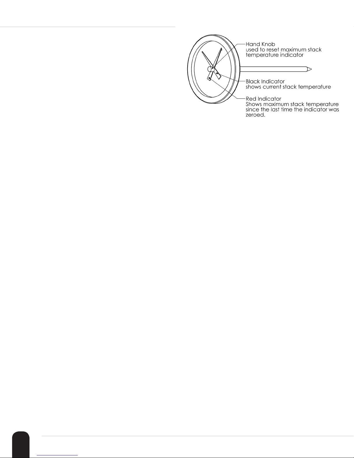
Diagram 6.1–Stack
Temperature Gauge
6.8 Stack Temperature
Stack temperature is an important factor in the proper
functioning of a chimney. e chimney’s maximum
stack temperature must never exceed 400˚F. If the
chimney temperature exceeds 400˚F, consult with your
local dealer or with the factory on how to decrease the
maximum stack temperature. e stack temperature
must always increase to over 275˚F during every burn
cycle. If the stack temperature fails to exceed 275˚F
during each burn cycle, consult with your local dealer
or with the factory to increase the stack temperature.
6.8.1 Stack Temperature Gauge
A stack temperature gauge is shipped with each
G-Class furnace. This gauge must be installed in
the chimney within 4” from the point at which the
chimney penetrates the rear roof panel. The gauge is
installed by sliding it into a small hole drilled through
the chimney wall. The stack temperature gauge has a
red temperature indicator which shows the maximum
temperature measured since the last time the max
temperature dial was turned counterclockwise until it
contacted the black current temperature indicator.
Notice: Always turn the hand knob
very carefully. Only turn the hand knob
counterclockwise until the red maximum
temperature indicator gently touches the
black current temperature indicator.
Additionally, if there are any known issues with the
water supply we strongly recommend testing the
water to verify that the boiler treatment we supply
will provide adequate treatment. Such known issues
include:
• high chloride levels (salty taste).
• high iron levels (metallic taste, looks reddish).
• a lot of scaling in the toilet, on shower heat, or in
your teapot.
• needing to replace your domestic hot water heater
every 2 or 3 years.
• have corrosion on your water taps.
6.9 Water Quality & Treatment
Ensure the water that will be used to fill the water
jacket meets at least the following minimum criteria:
• does not have an odor
• is not discolored
• does not discolor after sitting in a container for a
number of days.
16
Owner’s manual for Polar Furnace models: G-2 & G-3
Wood Boiler Solutions (phone: 920-324-2007) are
water treatment professionals and they offer water
testing service for a reasonable fee. Simply browse to
their website (woodboilersolutions.com) and order a
water testing service kit to initiate this service. Wood
Boiler Solutions will test your water and make a
determination if your water supply is suitable for use
or not.
SECTION 6: HEATER SETUP
Once the water source is determined to be suitable,
begin filling the water jacket. After adding water for
about 5 minutes add the water treatment supplied
with your heater. Add the treatment by pouring it into
the overflow/fill pipe (diagram 4.1, item #11). Refer to
section 10 for more information regarding the water
treatment kit supplied with your heater.
6.10 Filling the Water Jacket
6.10.1 !! WARNING !!
Do NOT start a fire in the heater before filling the
heater water jacket with water. Starting a fire in
the heater without first filling the water jacket can
damage or destroy the heater.
6.10.2 !! DANGER!!
Do NOT pressurize this heater since it is designed
with an open system type water jacket. Pressurizing
the heater could result in damage to the heater,
damage to property, and could cause severe bodily
injury and even death.
6.11 Using the Water Level Sight
Tube
The water level sight tube is located on the side of the
heater. To check the water level in the heater turn the
valve handle into the vertical position. The sight tube
will fill with water showing the level of the water in
the water jacket. If the level is in the red, “ADD” zone,
add water until the level reaches the green, “FULL”
zone. After using the water level sight tube, always
turn the handle back into the horizontal position to
drain water from the sight tube. Output Settings (V.2)
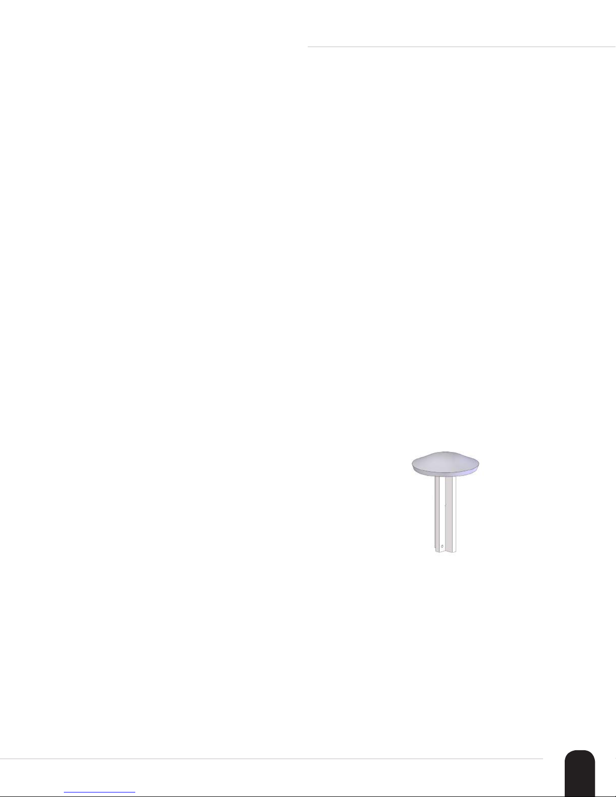
6.12 Anti-Evaporation Fill Pipe
Cap
An anti-evaporation cap ships with each heater
(diagram 6.2-Anti-Evaporation Cap). This cap
reduces the amount of evaporant escaping the water
jacket and helps maintain the water level over long
periods of time. The cap is installed into the overflow/
fill pipe. To install, slide the stem into the overflow
pipe. To locate the overflow/fill pipe, refer to diagram
4.1, item #11.
6.10.3 !! WARNING !!
This heater is a hydronic heater. This means that it
operates by heating water that is inside its water jacket.
This water jacket must be filled with water or a water/
glycol mixture before operating the heater. Filling the
water jacket can be achieved by adding water through
the overflow pipe on top of the heater or by hooking
the water supply hose to the drain/fill valve located
inside the rear access panel. Alternately, the water
jacket can be filled by adding water into any part of
the hot water distribution piping. Fill the heater until
the water level is in the green “FULL” zone (See
Section 6.11).
Note: Check the water level daily during the first few
weeks after the heater is installed and used.
Diagram 6.2–Anti-
Evaporation Cap
17
 Loading...