

POLA HP55 Handbook
HP55
Handbook
SL 6.7
MAIN SETTINGS (Run Mode).
START TIME-TEMPERATURE CYCLE.
Press START to switch-on time-temperature cycle: key lamp lights.
Pressing START during the cycle will be displayed time (hours and minutes)
passed from beginning phase: press + to go on next phase.
Phase in progress is indicated from its PROGRAM lamp.
SET TEMPERATURE HOLDING.
Press HOLD key to obtain thermoregulation temperature of value SEt.H
programmed under SET key: HOLD lamp lights (END disabled).
To return on thermoregulation program decided from cycle press again
HOLD key or START cycle: lamp off.
THERMOREGULATION PARAMETERS SETTING.
Press SET (key lamp flashes):
This message will be displayed instead of the
° Set arrival temperature of 1° segment.
Press + or - to modify, press SET to confirm.
At this point this message will be diplayed instead
of the ° Set arrival temperature of 2° segment.
Press + or - to modify, press SET to confirm.
At this point this message will be diplayed instead of the
° Set arrival temperature of 3° segment.
Press + or - to modify, press SET to confirm.
At this point this message will be diplayed instead of the
° Set arrival temperature of 4° segment.
Press + or - to modify, press SET to confirm.
At this point this message will be diplayed instead of the
°Set end cycle .
Press + or - to modify, press SET to confirm.
At this point this message will be diplayed instead of the
°C Set hold temperature.
Press + or - to modify, press SET to confirm.
At this point this message will be diplayed instead of the
°C /minute rising rate limitation (0.0° : no-limitation).
Press + or - to modify, press SET to confirm.
thermocouple programmable PID
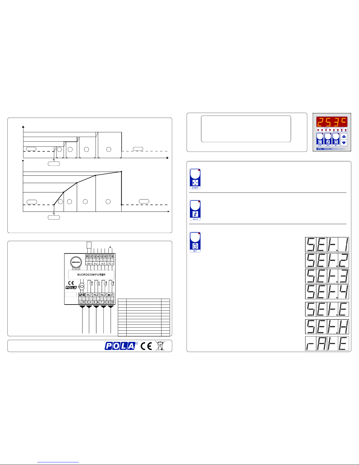
PROGRAM
When HOLD contition is entered (lamp HOLD on) SET value is equal to SEt.H.
When HOLD lamp is off HP55 SET in the time is determinated by program condition:
i.1, i.2, i.3, i.4 are settable in hours and minutes from 0.00 to 96.00 (4 days). During HOLD status program
timer stay in progress. After black-out program timer return in progress from where was halted.
Number of segments is limitated to | OPt.P | .
SEt.E
SEt.1
SEt.2
SEt.4
SEt.3
SET
END (see OPt.E) END (see OPt.E)
i.1 i.2 i.3 i.4
2
1
3 4
OPt.P = 4
time (hh.mm)
START
START
SEt.E
SEt.1
SEt.2
SEt.4
SEt.3
time (hh.mm)
i.1 i.2 i.3 i.4
2
1
3 4
SET
END (see OPt.E)
END (see OPt.E)
OPt.P = - 4
How to connect the contacts
Connect terminals on the terminal
block (contacts up to 4AMP.AC1)
to the loads as shown in the
diagram.
INSTALLATION
HP55
END cycle
230V LINE ac *
EXT.
OPER
*1)
DATA
PROT.
*2)
T.C.
*3)
SSR
- +
4V - +
HEAT on-off
MIN alarm
MAX alarm
OPTION
*2) DATA PROTECTION:
S.C. SETS are viewable but unchangeable
and COSt and boot is inhibited.
OPEN normal
*1) EXTERNAL COMMAND OPERATION:
S.C. START cycle command (no if HP55 is
in cycle).
100r END cycle command (END lamp flashes)
200r HALT timer but thermoregulate (segment
lamp flashes).
300r HALT timer and drift to T.amb (segment
lamp flashes and under key - is
displayed HALt).
400r put HP55 in HOLD condition (lamp
HOLD flashes; resume with START or
END command)
OPEN normal / resume from HALT condition
Recalibration:
HP55 is delivered calibrated for
thermocouple input (typ.
precision at full scale 0.2%).
Small adjust can be obtained by
Ad.tE COSt change.
For a NTC input accurate
recalibration apply 10 Kohm
resistor and trimmer to obtain on
display 25.0°C.
For a PT100 input accurate
recalibration apply 100 ohm
resistor and trimmer to obtain on
display 0.0°C.
How to connect the line
Connect 230V line on terminals L-N
Protect supply with adequate fuse.
RX and TRIMMER under aluminnium cover
*3) INPUT TYPE SELECTION
PnEt
epyttupnI XR
0=
Vm 00.35+...00.2- 7M4
1=
J
ct
057+...01-
C°
7M4
2=
K
ct
0031+...02-
C°
7M4
3=
N
ct
0031+...05-
C°
7M4
4=
R
ct
0071+...05-
C°
7M4
5=
S
ct
0071+...05-
C°
7M4
6=
T
ct
083+...02-
C°
7M4
7= CTN 0.001+...0.01-
C°
7M4
8=
001TP 0.084+...0.001-
C°
9K42
9=
001TP 084+...002-
C°
9K42
8=
0001TP 0.084+...0.002
C°
K942
9=
0001TP 084+...002-
C°
K942
As it company policy to continually improve the products the Manufacturers
reserve the right to make any modifications thereto without prior notice. They
cannot be held liable for any damage due to malfunction.
08.01.13
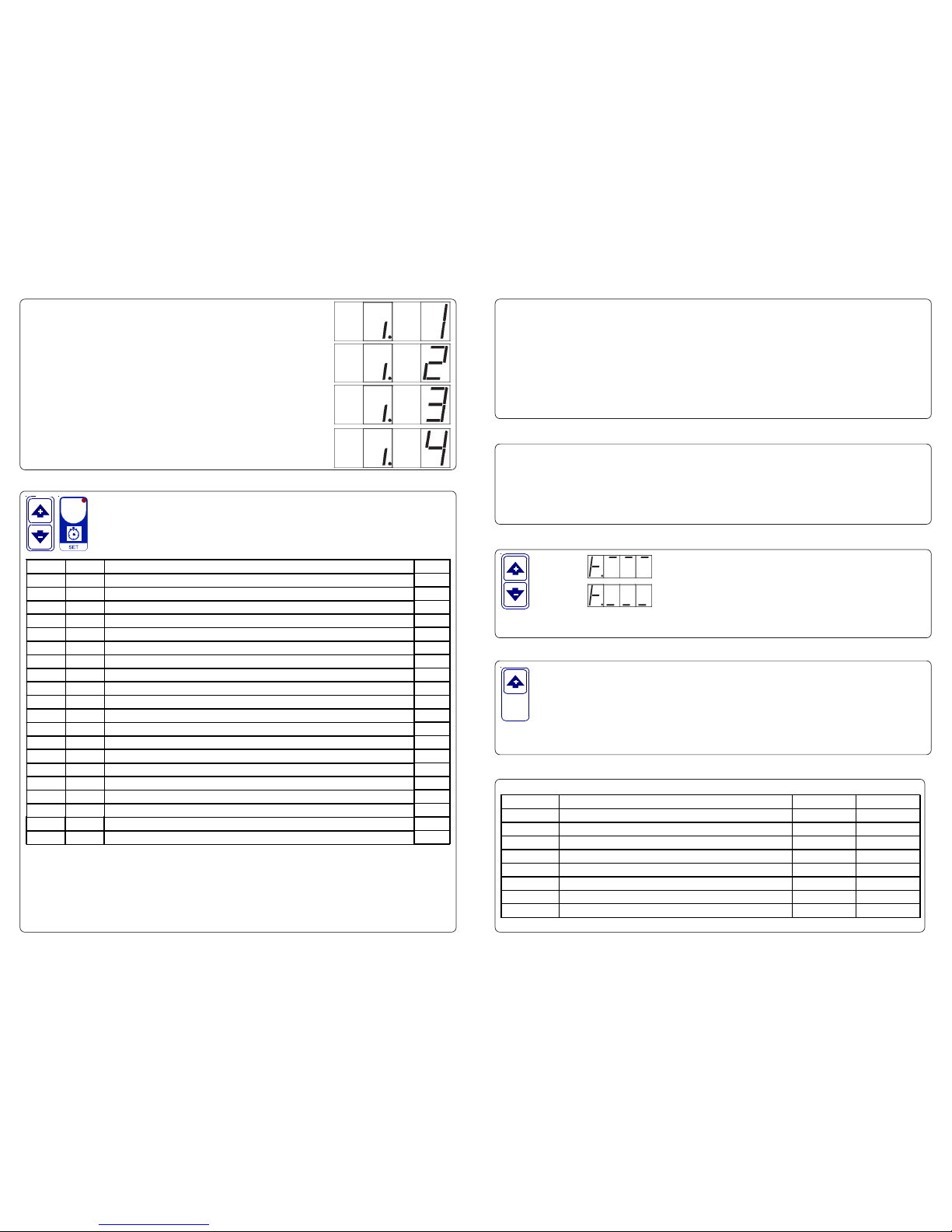
COSt PROGRAMMING (System constants)
These settings refer to the operation mode of the system and must be made on initial
startup. Press - / + at the same time for at least one second: the message C.O.S.t. will be
displayed. Press than repeatedly SET until the message regarding the chosen variable is
displayed (see table below): variable’s value and message will be displayed.
Press + or - to set a new value and then press SET to confirm. The next system constant
will then appear. You can press SET for at least 2 seconds to exit and return to the Run Mode.
At this point this message will be diplayed instead of the
hh.mm 2° segment duration .
Press + or - to modify, press SET to confirm.
At this point this message will be diplayed instead of the
hh.mm 3° segment duration .
Press + or - to modify, press SET to confirm.
At this point this message will be diplayed instead of the
hh.mm 4° segment duration .
Press + or - to modify, press SET to exit.
Mess. Value Meaning Note
ProP 4° PID proportional band *1)
cycL 4.0" PID cycle (=0" for 0-10V HISO output option)
intE 4.0" PID integration time
dEri 4.0" PID derivation time
SELF =1 PID mode (=0 normal; =1 self-tune) *2)
rEL.H 0° On-off relative shift from SET *3)
dIF.H 4° On-off differential (if diF.H=0° relay no.1 acts as PID)
t.on.H 1" On-off delay time to relay on
OPt.P =4 Number and type of program segments (see PROGRAM)
StAb 4° Stabilization range value. If 0° no stabilization works. *4)
OPt.E =1 =-1 drif to T.amb, no alarms ; =0 drift to T.amb ; =1 regulation SEt.E
AL._ _ -10° Minimum alarm set (see OP.A_ ) *5)
AL.^^ 10° Maximum alarm set (see OP.A^) *6)
t.on._ 1" Delay time to minimum alarm output
t.on.^ 1" Delay time to maximum alarm output
OP.A_ =1 =0 AL._ _ absolute setting ; =1 relative to SET
OP.A^ =1 =0 AL.^ ^ absolute setting ; =1 relative to SET
tEnP =1 J, K, N, R, S, T, NTC, PT100 input selection *7)
Ad.tE 0° Input temperature sensor correction (+ or -)
SEt.^ 350° SEt.1/.2/.3/.4/.E/.H maximum setting value limitation *8)
*1) PID regulation outputs to terminals i/o.1 and it's suitable for a solid state relay (4V DC input
minimum). Output % is viewable (1 second window) pressing - key.
See PROGRAM for determine actual SET.
*2) Self-tuning function works into -/+ ProP range from SET (out of this interval is zeroed). Self-
tuning value is re-computated every 16 x intE.
This processor is ready programmed with the following (variable) settings.
To return to these settings at any time (not if in.3 is closed):
Power off the processor, press SET key and keep it pressed giving power on:
boot message will be displayed (release now SET key).
SEt.1= 100° i.1=0.10 SEt.2= 200° i.2=0.10 SEt.3= 250° i.3=0.10 SEt.4= 300° i.4=0.10
SEt.E= 40° SEt.H=250° rAtE=10.0° The COSt values are shown in COSt paragraphs.
PRESET PROGRAMS
*3) On-off heating function outputs to no.1 relay. Output status is indicated by HEAT lamp.
See PROGRAM for determine actual SET.
Press + : will be displayed followed by
°Maximum Temperature Recording.
Press - : after 1 second (% out or End.o or HALt) will be displayed
followed by °Minimum Temperature Recording.
VIEWING TEMPERATURE RECORDING
Values recorder are memory permanent stored: for memory clear keep pushed + keys for more
than 3 seconds: CLEA message will be composed on display before clearing operation.
At this point this message will be diplayed instead of the
hh.mm 1° segment duration .
Press + or - to modify, press SET to confirm.
In some start-up conditions may be useful to work in "hand" mode (not if in.3 is closed).
Power off the processor, press + key and keep it pressed giving power on:
HAnd message will be displayed (release now + key).
Push + until is displayed number required to be handed (see table relays "N° Relay ")
and push SET for activing relay.
Pushing again + for increase relay number previous relay is disactivated.
You can press SET for a least two seconds to escape and return to the Run Mode.
MANUAL MODE
STATE INDICATION LAMPS
The lights situated at the bottom of the display show the state of the program.
Lamp. State N° Relay Contacts
PROG. 1 Interval 1 in progress
PROG. 2 Interval 2 in progress
PROG. 3 Interval 3 in progress
PROG. 4 Interval 4 in progress
END End cycle (disabled if module is in HOLD mode) 4 9-10
HEAT * Heat output ON 1 3-4
MIN * Minimum alarm temperature ON 2 5-6
MAX * Maximum alarm temperature ON 3 7-8
* Flashing lamps indicates delay in actioning (see COSt t.on.H, t.on._ , t.on.^ )
*5) Minimum alarm outputs to no.2 and it's indicated by MIN lamp. Differential is fixed to 1/2°C.
*6) Maximum alarm outputs to no.3 and it's indicated by MAX lamp. Differential is fixed to 1/2°C.
*7) Thermocouple selection:
*8) Absolute locking of setting operations can be obtained closing in.3 terminals.
=1 J (°C); =2 K (°C); =3 N (°C); =4 R (°C); =5 S (°C); =6 T (°C); =7 ntc SX POLA (°C);
changing RX resistor (see at the end): =8 PT100 2 wires (°C) res. 0.2°; =9 (°C) res. 1°.
°F range are obtainable setting negative number selection [example = -1 J (°F)].
*4) During programmed regulation if temperature is out of stabilization range segment lamp
flashes and program timer is halted.
 Loading...