

POLA HP17 Handbook

HP17
SL 3.1
Thermostat with alarm
Handbook
INSTALLATION
How to connect the line
Connect 230V line on terminals L-N.
Protect supply with adequate fuse.
How to connect the contacts
Connect terminals on the terminal block (contacts up to 4AMP.AC1).
*1
Other power voltage
if you required.
HP17
SX TEMPERATURE
PROBE
HEAT CONTACT
COOL CONTACT
ALARM
N.O. CONTACT
*2
ALARM
N.C. CONTACT
*2
230V LINE
*1
As it company policy to continually improve the products the Manufacturers
reserve the right to make any modifications thereto without prior notice. They
cannot be held liable for any damage due to malfunction.
07.01.13
*2
Alarm relay de excited or excited in normal condition referring to Cost, function rY.AL.
PRESET PROGRAMS (Bootstrap)
At delivery this processor is programmed with the following (variable) settings.
To return to these settings at any time.
Power off the processor, press ALARM MAX key and keep it pressed giving
power on: release ALARM MAX key when on the screen boot message
appears. t.SEt = 25.0° AL _ _ = 10.0° AL - - = 30.0°
The COSt values are shown in COSt Programming.
Press + : will be displayed followed by
°Maximum Temperature Recording.
Press - : will be displayed followed by
°Minimum Temperature Recording.
VIEWING TEMPERATURE RECORDING
Values recorder are memory permanent stored: for memory clear keep pushed + keys
for more than 3 seconds: CLEA message will be composed on display before clearing
operation.
MAIN SETTING (Run Mode)
TEMPERATURE SETTING
Press TEMP (key lamp flashes): this message will be displayed
instead of the ° Set temperature value.
Press + or - to modify, press SET to escape.
MINIMUM ALARM TEMPERATURE
Press MIN ALARM (key lamp flashes): this message will be
displayed instead of the ° Set Minimum temperature value .
Press + or - to modify (*), press ALARM MIN to escape.
TEMPERATURE SETTING
Press MAX ALARM (key lamp flashes): this message will be
displayed instead of the ° Set Maximum temperature value.
Press + or - to modify (*), press ALARM MAX to escape.
* If option o.ALA=1 (see COSt) the c.AL_ or c.AL- message appears on display.
If option o.ALA=2 (see COSt) the r.AL_ or r.AL- message appears on display.
How to connect the sensors
Connect the sensor provided as shown in the diagram. For remote connections
use a standard 0.5-square millimeter two-pole wire, taking great care over the
connections, by insulating and sealing the joins carefully. -O.C.- is displayed when the
temperature sensor wiring is open, -S.C.- is displayed when the temperature sensor
wiring is short circuit.
COSt PROGRAMMING (System constants)
These settings refer to the mode operation of the system and must be made
These settings refer to the operation mode of the system and must be made
on initial startup. Press - / + at the same time for at least one second: the
message C.O.S.t. will be displayed.
Press than repeatedly ALARM MAX until the message regarding the chosen
variable is displayed (see table below): variable’s value and message will be
displayed.
Press + or - to set a new value and then press ALARM MAX to confirm.
The next system constant will then appear.
You can press SET 2 for at least 2 seconds to exit and return to the Run Mode.
COOL
HEAT
TEMP. TEMP. TEMP.
MIN
ALARM
MAX
ALARM
AL. ON AL. ON
AL. OFF AL. OFF
0.2°
0.2°
AL _ _ AL - -t.SEt
1/2 diFF1/2 diFF
TEMP. TEMP.
MIN
ALARM
MAX
ALARM
AL. ON AL. ON
AL. OFF AL. OFF
0.2°
0.2°
TERM
TEMP. TEMP.
MIN
ALARM
MAX
ALARM
AL. ON AL. ON
AL. OFF AL. OFF
0.2°
0.2°
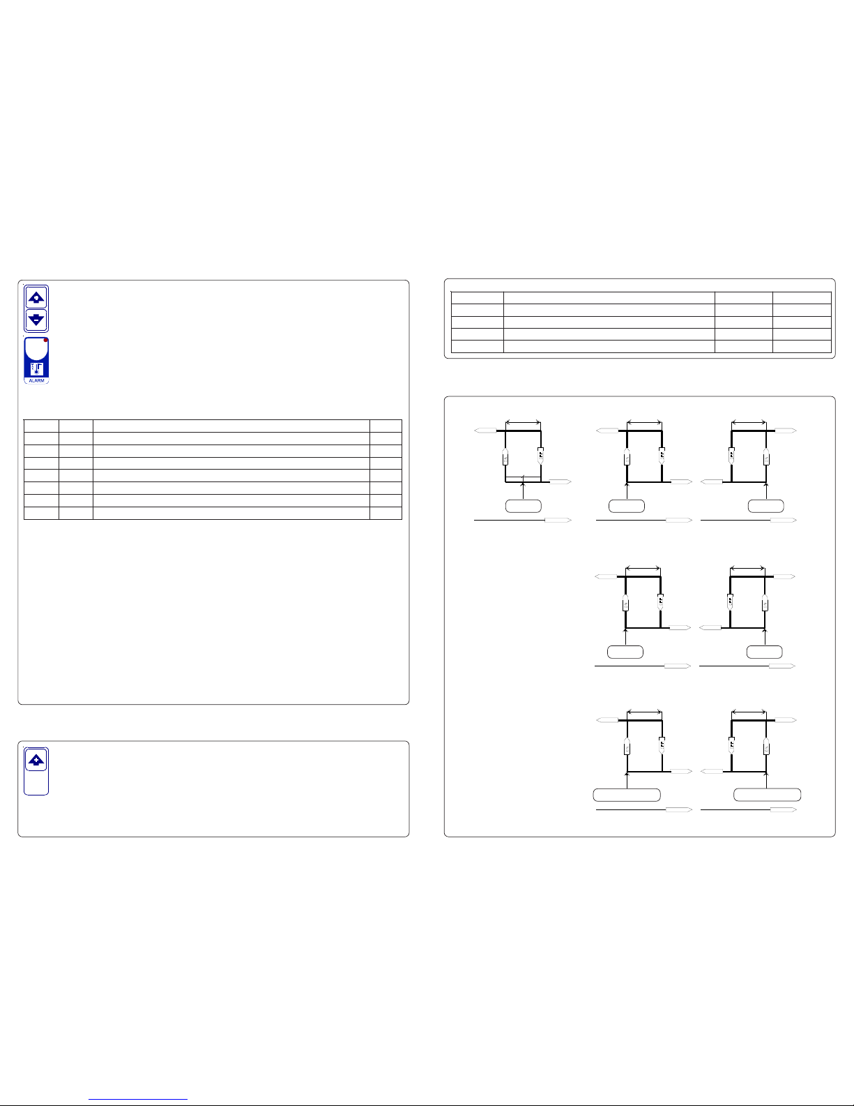
OPERATIVE DIAGRAMS
The light situayed at the bottom of the display show the state of the various relays as set out below:
STATE INDICATION LAMPS
*1) For more details see Operative Diagrams.
*2) o.ALA = 0 : Minimum and maximum alarm sets user settable (see ALARM keys).
*3) If o.ALA = 1 : Minimum or maximum absolute alarm set value.
If o.ALA = 2 : Minimum or maximum relative alarm set value.
For more details see Operative Diagrams.
*4) :=1 : °C Temperature range.
=2 : °F Temperature range.
*5) You can correct the readings on the various sensor (+ or -).
o.ALA = 0
o.ALA = 1
C.AL-
C.AL_
o.ALA = 2
t.SEt + C.AL_ t.SEt + C.AL-
o.ALA = 1 : Minimum and maximum alarm absoloute sets (see COST *3).
o.ALA = 2 : Minimum and maximum alarm relative sets (see COST *3).
diFF
.sseM eulaV gninaeM etoN
FFid
°2.0
laitnereffidC°
)1*
ALA.o
0=
edomgnittesmralA
)2*
_LA.C
°0.0
mralamuminimerutarepmetteSC°
)3*
-LA.C
°0.04
mralamumixamerutarepmetteSC°
)3*
PnEt
1=
)F°2=,C°1=(noitatneserpererutarepmeT
)4*
Et.dA
°0.0
)-ro+(noitcerrocrosneserutarepmettupnIC°
)5*
LA.Yr
0=
noitidnoclamronninoitatitcxeyalermralA
)6*
.pmaL etatS yaleR°N stcatnoC
TAEH
nOtaeH 1 4-3
LOOC
nOlooC 1 5-4
NIM.LA
nOmralAmuminiM 2 8-7-6
XAM.LA
nOmralAmumixaM 2 8-7-6
*6) rY.AL =0 : Relay de excited in normal condition
rY.AL =1 : Relay excited in normal condition.
MANUAL MODE
In some start-up conditions may be useful to work in "hand" mode.
Power off the processor, press + key and keep it pressed giving power on:
HAnd message will be displayed (release now + key).
Push + until is displayed number required to be handed (see table relays "N°
Relay") and push ALARM MAX for activing relay.
Pushing again + for increase relay number previous relay is disactivated.
You can press ALARM MAX for a least two seconds to escape and return to the Run Mode.
 Loading...