

PoKeys PoKeys57CNC User Manual
PoKeys57CNC
User’s manual
Version: 23/3/2017

PoKeys user manual
2
www.poscope.com
Please read the following notes
1. All information included in this document is current as of the date this document is issued. Such information, however, is subject to
change without any prior notice.
2. PoLabs does not assume any liability for infringement of patents, copyrights, or other intellectual property rights of third parties by or
arising from the use of PoLabs products or technical information described in this document. No license, express, implied or otherwise,
is granted hereby under any patents, copyrights or other intellectual property rights of PoLabs or others. PoLabs claims the copyright
of, and retains the rights to, all material (software, documents, etc.) contained in this release. You may copy and distribute the entire
release in its original state, but must not copy individual items within the release other than for backup purposes.
3. Descriptions of circuits, software and other related information in this document are provided only to illustrate the operation of the
products and application examples. You are fully responsible for the incorporation of these circuits, software, and information in the
design of your equipment. PoLabs assumes no responsibility for any losses incurred by you or third parties arising from the use of
these circuits, software, or information.
4. PoLabs has used reasonable care in preparing the information included in this document, but PoLabs does not warrant that such
information is error free. PoLabs assumes no liability whatsoever for any damages incurred by you resulting from errors in or
omissions from the information included herein.
5. PoLabs devices may be used in equipment that does not impose a threat to human life in case of the malfunctioning, such as:
computer interfaces, office equipment, communications equipment, test and measurement equipment, audio and visual equipment,
home electronic appliances, machine tools, personal electronic equipment, and industrial robots.
6. Measures such as fail-safe function and redundant design should be taken to ensure reliability and safety when PoLabs devices are
used for or in connection with equipment that requires higher reliability, for example: traffic control systems, anti-disaster systems,
anticrime systems, safety equipment, medical equipment not specifically designed for life support, and other similar applications.
7. PoLabs devices shall not be used for or in connection with equipment that requires an extremely high level of reliability and safety, as
for example: aircraft systems, aerospace equipment, nuclear reactor control systems, medical equipment or systems for life support
(e.g. artificial life support devices or systems), and any other applications or purposes that pose a direct threat to human life.
8. You should use the PoLabs products described in this document within the range specified by PoLabs, especially with respect to the
maximum rating, operating supply voltage range and other product characteristics. PoLabs shall have no liability for malfunctions or
damages arising out of the use of PoLabs products beyond such specified ranges.
9. Although PoLabs endeavors to improve the quality and reliability of its products, semiconductor products have specific characteristics
such as the occurrence of failure at a certain rate and malfunctions under certain use conditions. Further, PoLabs products are not
subject to radiation resistance design. Please be sure to implement safety measures to guard them against the possibility of physical
injury, and injury or damage caused by fire in the event of the failure of a PoLabs product, such as safety design for hardware and
software including but not limited to redundancy, fire control and malfunction prevention, appropriate treatment for aging
degradation or any other appropriate measures.
10. Usage: the software in this release is for use only with PoLabs products or with data collected using PoLabs products.
11. Fitness for purpose: no two applications are the same, so PoLabs cannot guarantee that its equipment or software is suitable for a
given application. It is therefore the user's responsibility to ensure that the product is suitable for the user's application.
12. Viruses: this software was continuously monitored for viruses during production, however the user is responsible for virus checking the
software once it is installed.
13. Upgrades: we provide upgrades, free of charge, from our web site at www.poscope.com. We reserve the right to charge for updates or
replacements sent out on physical media.
14. Please contact a PoLabs support for details as to environmental matters such as the environmental compatibility of each PoLabs
product. Please use PoLabs products in compliance with all applicable laws and regulations that regulate the inclusion or use of
controlled substances, including without limitation, the EU RoHS Directive. PoLabs assumes no liability for damages or losses occurring
as a result of your noncompliance with applicable laws and regulations.
15. Please contact a PoLabs support at support@poscope.com if you have any questions regarding the information contained in this
document or PoLabs products, or if you have any other inquiries.
16. The licensee agrees to allow access to this software only to persons who have been informed of and agree to abide by these
conditions.
17. Trademarks: Windows is a registered trademark of Microsoft Corporation. PoKeys, PoKeys55, PoKeys56U, PoKeys56E, PoKeys57U,
PoKeys57E, PoKeys57CNC, PoKeys57CNCdb25, PoScope, PoLabs and others are internationally registered trademarks.

PoKeys user manual
3
www.poscope.com
Contents
1. Introduction ..................................................................................................................................... 7
2. Features ........................................................................................................................................... 8
3. Device hardware description........................................................................................................... 9
3.1. PoKeys57CNC connector pinout ............................................................................................ 11
Pin types ........................................................................................................................................ 11
Power supply ................................................................................................................................. 11
SSR (Solid State Relay) connector .................................................................................................. 12
Relays connector ........................................................................................................................... 12
Galvanically isolated I/Os .............................................................................................................. 12
LCD connector ............................................................................................................................... 12
Pendant connector ........................................................................................................................ 13
Encoders connector ....................................................................................................................... 15
ADC connector ............................................................................................................................... 15
Motor connectors 1-8 ................................................................................................................... 16
Axis switches connector ................................................................................................................ 16
Additional limit switches ............................................................................................................... 16
DB-25 (LPT-port) IO connector ...................................................................................................... 17
3.2. Pin types and specifications .................................................................................................. 18
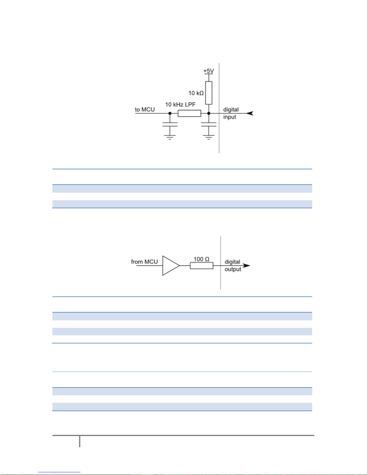
Type DI5P: Digital input with filtering ........................................................................................... 18
Type DO5: 5 V digital output ......................................................................................................... 18
Type DO5_D: 5 V digital output without resistor .......................................................................... 18
Type DIO33: 3,3 V digital input or output ..................................................................................... 19
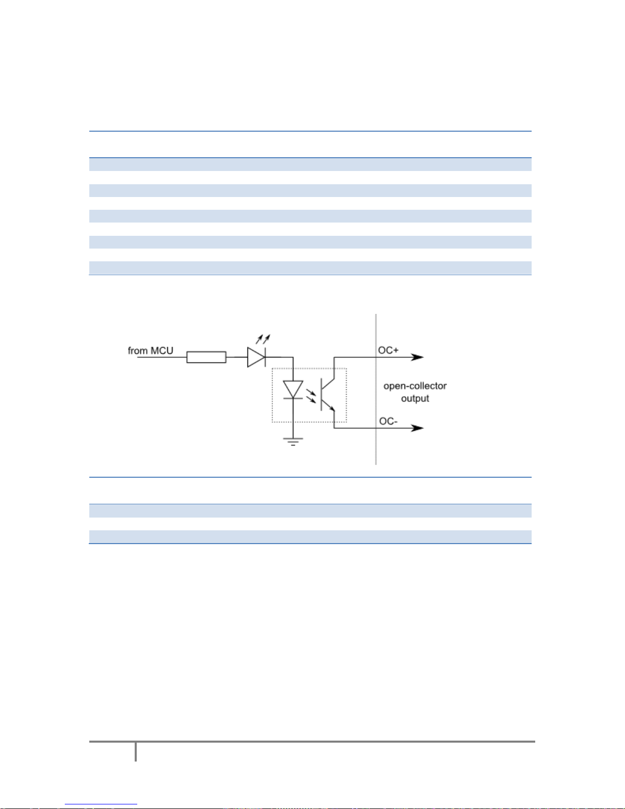
Type OCOC: opto-coupled open-collector output ........................................................................ 19
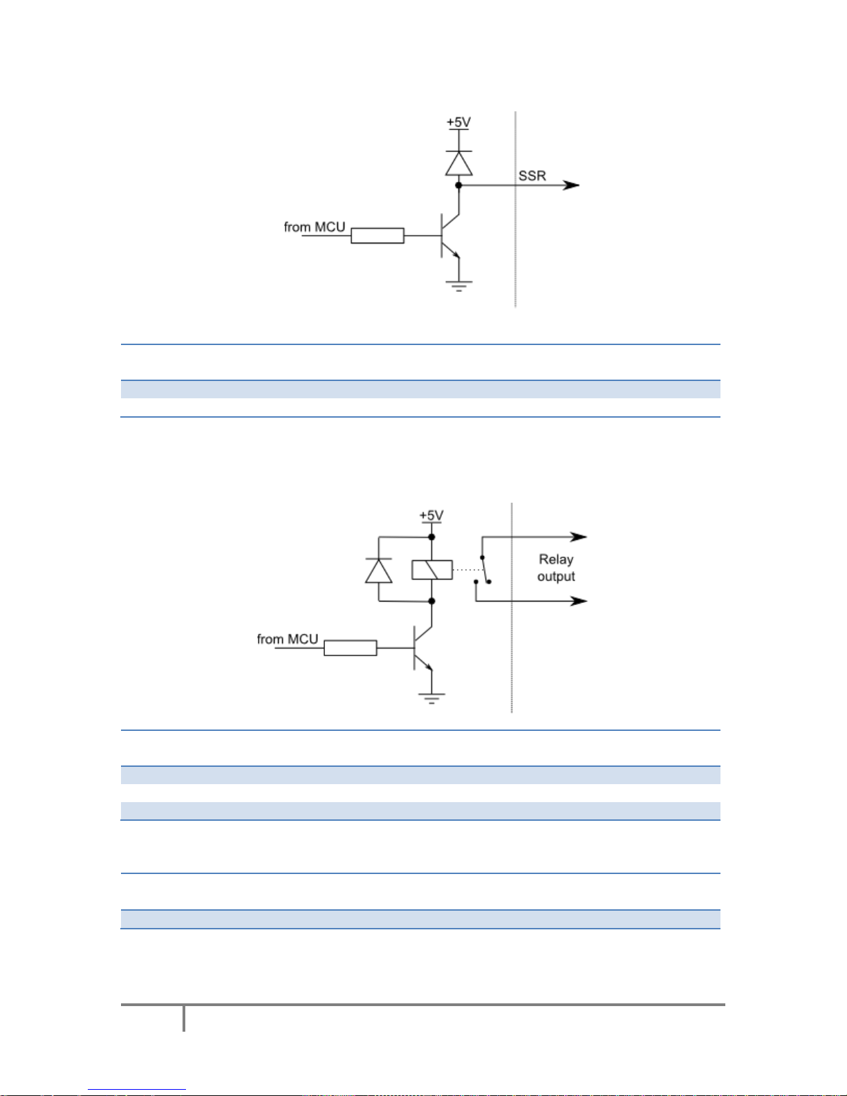
Type OCSSR: open-collector output for SSR (Solid State Relay) .................................................... 20
Type REL: relay output .................................................................................................................. 20
Type AN33: 3.3 V analog input ...................................................................................................... 20
Type AN33F: 3.3 V analog input with low-pass filter .................................................................... 21
3.3. Status LEDs ............................................................................................................................ 21
4. Requirements ................................................................................................................................ 22
5. Technical specifications ................................................................................................................. 23
5.1. PoKeys57CNC dimensions ..................................................................................................... 23
5.2. Environment specifications ................................................................................................... 23
6. Installation ..................................................................................................................................... 24

PoKeys user manual
4
www.poscope.com
6.1. Using USB .............................................................................................................................. 24
6.2. Using Ethernet - direct connection between PoKeys57CNC and computer ......................... 24
6.3. Using Ethernet - PoKeys57CNC connected to a network with DHCP server ......................... 25
6.1. Using USB and Ethernet ........................................................................................................ 25
6.2. Motor drivers and peripherals installation ........................................................................... 25
7. PoKeys configuration options ........................................................................................................ 26
7.1. Digital inputs and outputs ..................................................................................................... 26
PoKeys configuration software usage ........................................................................................... 26
7.2. Digital counters ..................................................................................................................... 28
PoKeys configuration software usage ........................................................................................... 28
7.3. Encoders ................................................................................................................................ 29
PoKeys configuration software usage ........................................................................................... 30
7.4. Pulse engine .......................................................................................................................... 32
Pulse engine status/control dialog parts ....................................................................................... 33
Axis configuration panel ................................................................................................................ 34
Homing algorithm configuration ................................................................................................... 35
Common homing algorithm configurations .................................................................................. 36
Limit and home switch filters ........................................................................................................ 37
PoStep drivers configuration ......................................................................................................... 37
Connecting PoStep drivers to PoKeys57CNC ................................................................................. 38
7.5. Matrix keyboard .................................................................................................................... 40
PoKeys configuration software usage ........................................................................................... 40
7.6. Analog inputs ......................................................................................................................... 42
PoKeys configuration software usage ........................................................................................... 42
7.7. Joystick mapping ................................................................................................................... 43
PoKeys configuration software usage ........................................................................................... 43
7.8. PWM outputs ........................................................................................................................ 44
PoKeys configuration software usage ........................................................................................... 45
7.9. LCD ......................................................................................................................................... 46
PoKeys configuration software usage ........................................................................................... 46
7.10. PoExtBus ............................................................................................................................ 49
PoKeys configuration software usage ........................................................................................... 49
PoExtBus connector type .............................................................................................................. 49
7.11. PoNET ................................................................................................................................ 50

PoKeys user manual
5
www.poscope.com
Adding new devices ....................................................................................................................... 51
PoNET kb48CNC keyboard............................................................................................................. 52
7.12. Failsafe settings ................................................................................................................. 53
7.13. Peripheral communication protocols ................................................................................ 54
I2C protocol .................................................................................................................................... 54
1-wire............................................................................................................................................. 55
7.14. EasySensors ....................................................................................................................... 56
EasySensors configuration dialog .................................................................................................. 56
Scan for I2C sensors ....................................................................................................................... 56
Scan for 1-wire sensors ................................................................................................................. 57
Add DHTxx 1-Wire sensor .............................................................................................................. 57
Add analog sensor ......................................................................................................................... 57
List of supported sensors .............................................................................................................. 59
7.15. USB interface configuration .............................................................................................. 60
Start options .................................................................................................................................. 60
Communication interval ................................................................................................................ 60
Enabling/disabling the interfaces .................................................................................................. 61
7.16. Network device functionality ............................................................................................ 62
Device discovery ............................................................................................................................ 62
Default network settings ............................................................................................................... 63
Connecting to device in other network ......................................................................................... 63
Security .......................................................................................................................................... 64
Web interface (dashboard) ........................................................................................................... 65
Modbus .......................................................................................................................................... 68
Reporting data to network server with PoKeys57CNC device ...................................................... 71
7.17. Changing User ID number ................................................................................................. 77
7.18. Saving current configuration to file ................................................................................... 77
7.19. PoIL core functionality ....................................................................................................... 77
8. Device recovery mode ................................................................................................................... 78
9. Frequently asked questions .......................................................................................................... 79
10. Errata information ..................................................................................................................... 80
PoKeys device resets when external power supply is applied or removed .................................. 80
External pull-up resistor needed on the probing input ................................................................. 80
11. Grant of license ......................................................................................................................... 81

PoKeys user manual
6
www.poscope.com

PoKeys user manual
7
www.poscope.com
1. Introduction
PoKeys products line consists of simple, easy-to-use USB and network devices with the extended list
of features making them powerful input/output devices. PoKeys57CNC features both USB and
Ethernet connectivity, giving user an option to select the preferred connection for the application.
The device is highly adjustable and as such requires no complex knowledge on device programming.
PoKeys57CNC is a blend between general purpose PoKeys device and motor controller. The device is
targeted primarily for controlling up to 8 STEP/DIR signal driven motors (stepper motors, servo
drives, etc.) in various applications with the addition of powerful PoKeys device features. Device
contains dedicated connectors for connections with motor drivers, pendants, (HD44780-compatible)
LCD module, etc. In addition, 5 analog inputs with 12-bit resolution are available. The device also
features four galvanically-isolated open-collector outputs and 0 to 10 V analog output.
The device runs the PoIL core and is fully compatible with PoBlocks graphical programming software,
bringing Programmable Logic Controller to a motor controller board. PoBlocks can be used to simply
automate different peripherals and interchange data with other software applications that are using
PoKeys57CNC device.
PoKeys USB products integrate support for virtual USB keyboard and USB joystick, which can be used
to emulate a standard USB keyboard and joystick. Digital input pins can be mapped to virtual
keyboard and joystick keys, while analog inputs can be mapped to virtual joystick axes. Configuration
is simple by using our intuitive graphical PoKeys configuration application, where each function can
also be tested.
A dedicated PoExtBus/PoNET connector can be used to extend the number of digital outputs for
additional 80 outputs in the form of either relay outputs or open-collector outputs. It can also be
used to connect various additional peripherals (e.g. PoKeysKBD48CNC pendant) and I2C sensors.
Third-party application developers that are adding the support for PoKeys devices, are encouraged to
use the supplied communication DLL that can be simply used in the different .NET framework based
applications and various other programming languages that provide support for ActiveX interface.
There is even an open-source cross-platform C library available at https://bitbucket.org/mbosnak/pokeyslib.
To aid developers that are communicating with PoKeys devices on the low-level, the extensive
documentation on device communication protocol can be downloaded free of charge from the
product webpage.

PoKeys user manual
8
www.poscope.com
2. Features
- Compatible with USB 1.1/2.0 HID standard,
- standard English USB keyboard simulation (with triggering support for up/down keys),
- standard USB joystick simulation (6 axes, 32 buttons with triggering support),
- Ethernet 10/100 with DHCP client or fixed IP support,
- TCP or UDP connection with the device,
- Modbus TCP support (access to digital IO, analog inputs, encoder values, digital counters
values, PWM outputs, LCD display, PoExtBus devices, matrix keyboard status),
- web interface with newly designed dashboard and I/O status display with multiple user
accounts,
- 28 digital inputs or outputs (software configurable) with pull-up resistors and available as
virtual USB keyboard keys. There are additional 4 dedicated digital outputs,
- 5 analog inputs (12-bit) with digital low-pass filtering (4 analog inputs also include analog
low-pass filter with 1.9 kHz cut-off frequency),
- multiple encoder pair inputs with three additional dedicated high-speed encoder and one
ultra high-speed encoder inputs,
- digital counters on specific digital input pins,
- high performance 8-axis 125 kHz pulse engine with dedicated motor connectors,
- up to 16x8 matrix keyboard with triggered keys/alternate function support,
- up to 4 high-speed fully configurable PWM outputs (25MHz PWM timer) - two of them with
open-collector transistor outputs,
- dedicated connector for HD44780-based character LCD (up to 4x20 characters),
- dedicated connector for PoPendant1,
- PoExtBus support for adding up to 10 external shift registers (e.g. PoExtBusOC16,
PoExtBusRE, etc.),
- PoNET devices support (48-key CNC keyboard),
- fail-safe support in case of communication interruption,
- support for up to 100 sensors, that can be connected to I
2
C bus, 1-wire bus or on the general
purpose analog inputs,
- intuitive and user-friendly software,
- third-party support via communication DLL library and extensive protocol specification
document that allows porting to other systems.
PoKeys user manual
9
www.poscope.com
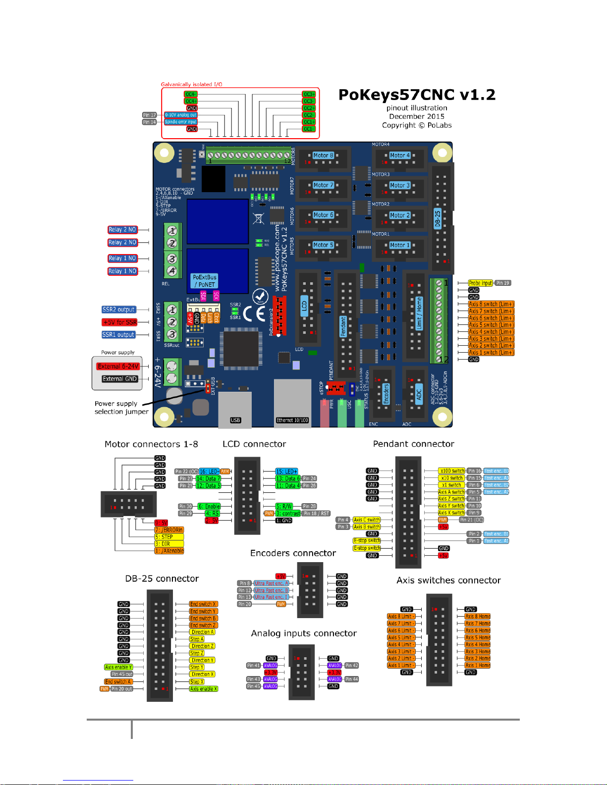
3. Device hardware description
1
2

PoKeys user manual
10
www.poscope.com
PoKeys user manual
11
www.poscope.com
3.1. PoKeys57CNC connector pinout
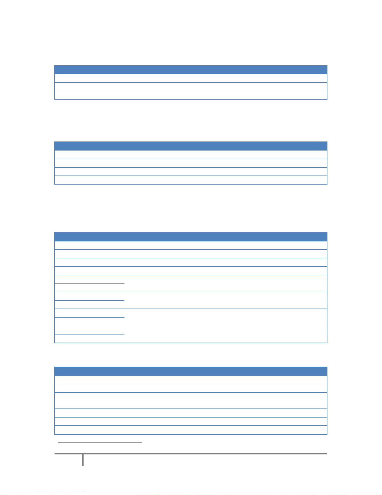
Pin types
Type code
Description
DI5P
5 V digital input with input filtering
DI33P
3,3 V digital input with input filtering
DO5
5 V digital output
DO5_D
5 V digital output without series resistor
DIO33
3,3 V digital input or output without filtering
OCOC
Opto-coupled open-collector output
OCSSR
Open-collector outputs for SSR
REL
Relay output
AN33
3,3 V analog input without filtering
AN33F
3,3 V analog input with 1,9 kHz low-pass
filtering
See chapter 3.2 Pin types for details on the listed pin types.
Power supply
Pin
Type
Function
1
Supply input
Positive power supply 6-26V (marked with +)
2
Supply input
Negative power supply (ground)
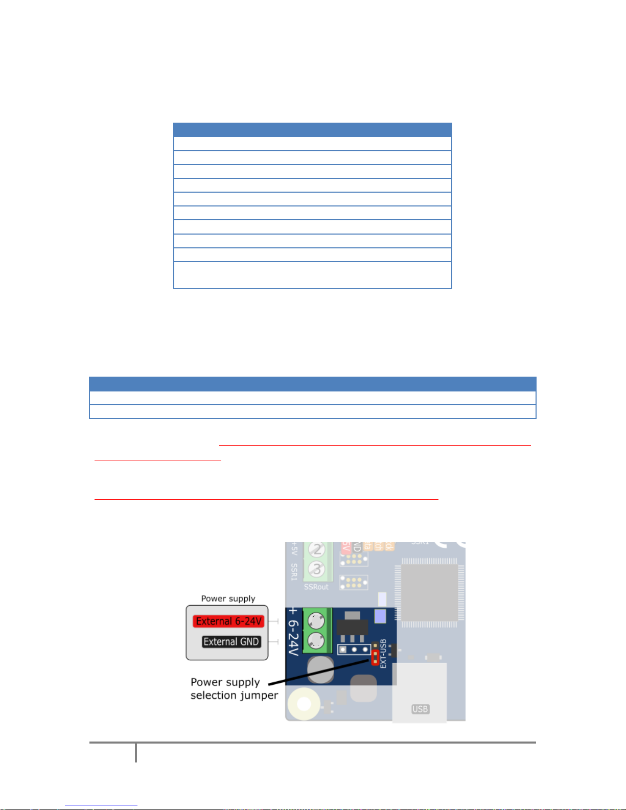
PoKeys57CNC requires external 6-26V power supply to be connected to the board in order for the
device to operate correctly (device may not operate according to the specifications if the external
power supply is not present). The device uses switching power converter to scale down the input
power supply to 5V. The power supply should be capable of providing at least 2.5W.
The PoKeys57CNC v1.2 features a jumper to select the power supply source. Move the jumper to
the ‘USB’ position during testing the board without the external power supply connected. Otherwise,
put the jumper to the ‘EXT’ position.
1
2
PoKeys user manual
12
www.poscope.com
SSR (Solid State Relay) connector
Pin
Type
Function
1
OCSSR
SSR2 output
2
+5V
+5V output (power supply to SSR relay)
3
OCSSR
SSR1 output
The solid state relays should be connected between +5V output and corresponding SSR output pin.
Note: all +5V output pins on the board share the same power supply and the current is distributed to
all loads.
Relays connector
Pin
Type
Function
1
REL
Relay 2 NO
2
REL
Relay 2 common
3
REL
Relay 1 NO
4
REL
Relay 1 common
Galvanically isolated I/Os
This connector contains special I/O signals that are galvanically isolated from the rest of the board.
Signals on pins 2 and 3 should only be referenced to GNDi points (available on pins 1 and 4).
Pin
Type
Label
Function
1
GNDi
GNDi
Isolated ground connection (for use only with signals on this connector)
2
DI5P
SpEr
Spindle error input
3 - 10V
0-10V analog output
4
GNDi
GNDi
Isolated ground connection
5
OCOC
OC4+
Open collector output 4
6
OCOC
OC4-
7
OCOC
OC3+
Open collector output 3
8
OCOC
OC3-
9
OCOC
OC2+
Open collector output 2
10
OCOC
OC2-
11
OCOC
OC1+
Open collector output 1
12
OCOC
OC1-
LCD connector
Pin
Type
Label
Function
1
GND
GND
Ground
2
+5V
+5V
+5V power supply for LCD
3
DIO33
RST
LCD contrast voltage, also used as PoKeys pin 18 with PWM and reset pin
(see Device recovery mode for more details)
4
DIO33
RS
LCD RS signal, also used as PoKeys pin 291
5
DIO33
R/W
LCD R/W signal, also used as PoKeys pin 28
6
DIO33
E
LCD Enable signal, also used as PoKeys pin 301
1
Digital counter functionality can be enabled for this pin

PoKeys user manual
13
www.poscope.com
7 - -
not connected
8 - -
not connected
9 - -
not connected
10 - -
not connected
11
DIO33
D4
LCD D4 signal, also used as PoKeys pin 26
12
DIO33
D5
LCD D5 signal, also used as PoKeys pin 25
13
DIO33
D6
LCD D6 signal, also used as PoKeys pin 24
14
DIO33
D7
LCD D7 signal, also used as PoKeys pin 23
15
+5V
LED+
+5 V power supply for LCD backlight with 4,7 Ω resistor in series
16
OC
LED-
Open-collector output (max. 100 mA), also used as PoKeys pin 22 with
PWM
Pendant connector
Pin
Type
Label
Function
1
+5V
+5V
+5 V power supply to pendant (used for encoder/MPG power)
2
GND
GND
Ground
3
GND
GND
Ground
4
DI33P
E-stop
E-stop signal input, also used as PoKeys pin 52 (connect E-stop switch
between pins 4 and 6) - see notes below
5
DIO33
FastEncA
Encoder channel A, also used as PoKeys pin 12
6
GND-E
E-Stop
E-stop switch GND - see notes below
7
DIO33
FastEncB
Encoder channel B, also used as PoKeys pin 22
8
GND
GND
Ground
9
+5V
LED+
+5 V power supply for pendant LED
10
DI33P
Ax-B
Axis B selection signal, also used as PoKeys pin 32
11
OC
LED-
Open-collector output (max. 100 mA), also used as PoKeys pin 21 with
PWM
12
DI33P
Ax-C
Axis C selection signal, also used as PoKeys pin 42
13
DI33P
Ax-X
Axis X selection signal, also used as PoKeys pin 92
14 - -
not connected
15
DI33P
Ax-Y
Axis Y selection signal, also used as PoKeys pin 102
16 - -
not connected
17
DI33P
Ax-Z
Axis Z selection signal, also used as PoKeys pin 112
18
GND
GND
Ground
19
DI33P
Ax-A
Axis A selection signal, also used as PoKeys pin 52
20
GND
GND
Ground
21
DI33P
Step x1
Step x1 selection signal, also used as PoKeys pin 62
22
GND
GND
Ground
23
DI33P
Step x10
Step x10 selection signal, also used as PoKeys pin 152
24
GND
GND
Ground
25
DI33P
Step x100
Step x100 selection signal, also used as PoKeys pin 162
26
GND
GND
Ground
Note: E-stop switch can be connected either to dedicated E-stop connector (red 4-pin connector) or
to pendant connector (a combination of both is also allowed since both are wired in series).
2
Digital counter functionality can be enabled for this pin

PoKeys user manual
14
www.poscope.com
a) E-stop switch is connected to dedicated 4-pin E-stop connector between pins 2 and 3.
Jumper 'NeST' must be removed and inserted into the pendant connector between pins 4
and 6
b) E-stop switch is connected to pendant connector (between pins 4 and 6). Jumper 'NeST' must
be present
c) Two E-stop switches are connected - one to dedicated 4-pin E-stop connector (betwen pins 2
and 3) and one to pendant connector (between pins 4 and 6).

PoKeys user manual
15
www.poscope.com
Encoders connector
Pin
Type
Label
Function
1
+5V
+5V
Axis enable signal (inverted)
2
GND
GND
Ground
3
DIO33
uFEA
Ultra-fast encoder A-channel signal input, also used as PoKeys pin 8
4
GND
GND
Ground
5
DIO33
uFEB
Ultra-fast encoder B-channel signal input, also used as PoKeys pin 12
6
GND
GND
Ground
7
DIO33
uFEI
Ultra-fast encoder index signal input, also used as PoKeys pin 13
8
GND
GND
Ground
9
DIO33
PK20
PoKeys pin 20 with PWM3
10
GND
GND
Ground
ADC connector
Pin
Type
Label
Function
1
GND
GND
Ground
2
GND
GND
Ground
3
AN33F
PK41
PoKeys pin 41
4
AN33F
PK42
PoKeys pin 42
5
+3,3V
+3,3V
6 +3,3V
+3,3V
7 AN33F
PK43
PoKeys pin 43
8
AN33F
PK44
PoKeys pin 44
9
AN33/DIO33
PK45
PoKeys pin 45
10
GND
GND
Ground
3
Digital counter functionality can be enabled for this pin

PoKeys user manual
16
www.poscope.com
Motor connectors 1-8
Pin
Type
Label
Function
1
DO5
/AXEn
Axis enable signal (inverted)
2
GND
GND
Ground
3
DO5
DIR
Direction signal
4
GND
GND
Ground
5
DO5
STEP
Step signal
6
GND
GND
Ground
7
DI5P
/ERRORin
Error input signal (from stepper driver to PoKeys)
8
GND
GND
Ground
9
+5V
5V
+5V output to stepper driver
10
GND
GND
Ground
Axis switches connector
Pin
Type
Label
Function
1
GND
GND
Ground
2
GND
GND
Ground
3
DI5P
AX8-
Axis 8 limit- switch
4
DI5P
AX8 H
Axis 8 home switch
5
DI5P
AX7-
Axis 7 limit- switch
6
DI5P
AX7 H
Axis 7 home switch
7
DI5P
AX6-
Axis 6 (C) limit- switch
8
DI5P
AX6 H
Axis 6 (C) home switch
9
DI5P
AX5-
Axis 5 (B) limit- switch
10
DI5P
AX5 H
Axis 5 (B) home switch
11
DI5P
AX4-
Axis 4 (A) limit- switch
12
DI5P
AX4 H
Axis 4 (A) home switch
13
DI5P
AX3-
Axis 3 (Z) limit- switch
14
DI5P
AX3 H
Axis 3 (Z) home switch
15
DI5P
AX2-
Axis 2 (Y) limit- switch
16
DI5P
AX2 H
Axis 2 (Y) home switch
17
DI5P
AX1-
Axis 1 (X) limit- switch
18
DI5P
AX1 H
Axis 1 (X) home switch
19
GND
GND
Ground
20
GND
GND
Ground
Additional limit switches
Pin
Type
Label
Function
1
GND
GND
Ground
2
DI5P
AX1+
Axis 1 (X) limit+ switch
3
DI5P
AX2+-
Axis 2 (Y) limit+ switch
4
DI5P
AX3+
Axis 3 (Z) limit+ switch
5
DI5P
AX4+
Axis 4 (A) limit+ switch
6
DI5P
AX5+
Axis 5 (B) limit+ switch
7
DI5P
AX6+
Axis 6 (C) limit+ switch
8
DI5P
AX7+
Axis 7 limit+ switch

PoKeys user manual
17
www.poscope.com
9
DI5P
AX8+
Axis 8 limit+ switch
10
GND
GND
Ground
11
GND
GND
Ground
12
DI5P
Probe
Probe input
On PoKeys57CNC v1.0, v1.1 and v1.2 external pull-up resistor must
be used
DB-25 (LPT-port) IO connector
Warning: on PoKeys57CNC v1.1 the pinout is not compatible with the LPT-based stepper drivers since
the physical pin numbering sequence in PoKeys57CNC v1.1 differs from that of a real DB-25
connector. Check the pinout diagrams above.
The connector on the PoKeys57CNC v1.2 is compatible with the LPT-based stepper drivers.
Pin
Type
Label
Function
1
DO5
/AXEn1
Axis 1 (X) enable signal (inverted)
2
DO5
STEP1
Step signal for axis 1 (X)
3
DO5
DIR1
Direction signal for axis 1 (X)
4
DO5
STEP2
Step signal for axis 2 (Y)
5
DO5
DIR2
Direction signal for axis 2 (Y)
6
DO5
STEP3
Step signal for axis 3 (Z)
7
DO5
DIR3
Direction signal for axis 3 (Z)
8
DO5
STEP4
Step signal for axis 4 (A)
9
DO5
DIR4
Direction signal for axis 4 (A)
10
DI5P
AX3+
Axis 3 (Z) limit+ switch
11
DI5P
AX5+
Axis 5 (B) limit+ switch
12
DI5P
AX2+
Axis 2 (Y) limit+ switch
13
DI5P
AX1+
Axis 1 (X) limit+ switch
14
DO5_D
PK20
PoKeys pin 20 (output only)
15
DI5P
AX4+
Axis 4 (A) limit+ switch
16
DO5_D
PK45
PoKeys pin 45 (output only)
17
DO5
/AXEn2
Axis 2 (Y) enable signal (inverted)
18
GND
GND
Ground
19
GND
GND
Ground
20
GND
GND
Ground
21
GND
GND
Ground
22
GND
GND
Ground
23
GND
GND
Ground
24
GND
GND
Ground
25
GND
GND
Ground
26
GND
GND
Ground
PoKeys user manual
18
www.poscope.com
3.2. Pin types and specifications
Type DI5P: Digital input with filtering
Symbol
Parameter
Min
Max
Unit
V
DI5P,MAX
maximum voltage applied to DI5P pin
-
5,5 V V
DI5P,LOW
applied voltage for LOW state
-
0,2 V V
DI5P,HIGH
applied voltage for HIGH state
1,6 - V
Type DO5: 5 V digital output
Symbol
Parameter
Min
Max
Unit
I
DO5,MAX
maximum current supplied by DO5 pin
- 8 mA
V
DO5,LOW
voltage of LOW state (no current)
-
0,1
V
V
DO5,HIGH
voltage of HIGH state (no current)
4,9 - V
R
DO5,HIGH
internal resistance of the digital output
100
TBD
Ohm
Type DO5_D: 5 V digital output without resistor
Symbol
Parameter
Min
Max
Unit
I
DO5_D,MAX
maximum current supplied by DO5 pin
-
50
mA
V
DO5_D,LOW
voltage of LOW state (no current)
-
0,1
V
V
DO5_D,HIGH
voltage of HIGH state (no current)
4,9 - V
PoKeys user manual
19
www.poscope.com
Type DIO33: 3,3 V digital input or output
Digital pin directly connected to MCU.
Symbol
Parameter
Min
Max
Unit
I
pu
pull-up current
0 (V
I
>= 3.3V)
-100
µA
Pin used as digital output
I
DO33,MAX
maximum current supplied by DO33 pin
- 4 mA
V
DO33,LOW
voltage of LOW state (no current)
0 - V
V
DO33,HIGH
voltage of HIGH state (no current)
-
3,3 V Pin used as digital input
V
DI5,MAX
maximum voltage applied to DI5 pin
-
5,0 V V
DI5,LOW
applied voltage for LOW state
-
0,8
V
V
DI5,HIGH
applied voltage for HIGH state
2,0 - V
Type OCOC: opto-coupled open-collector output
Symbol
Parameter
Min
Max
Unit
I
OCOC,MAX
maximum output current
-
50
mA
V
OCOC,DIFF
maximum voltage applied between OC+ and OC-
-
50
V
V
OCOC,ISO
isolation voltage (AC for 1min, R.H. 40-60%)
-
3000
V
RMS
PoKeys user manual
20
www.poscope.com
Type OCSSR: open-collector output for SSR (Solid State Relay)
Symbol
Parameter
Min
Max
Unit
I
OCSSR,MAX
maximum current sunk by OCSSR pin
-
500
mA
U
OCSSR,MAX
maximum voltage applied to OCSSR pin
- 5 V
Type REL: relay output
Symbol
Parameter
Min
Max
Unit
I
REL,28VDC
maximum current switching at 28 VDC
-
10 A I
REL,125VAC
maximum current switching at 125 VAC
-
10 A I
REL,240VAC
maximum current switching at 240 VAC
- 7 A
Type AN33: 3.3 V analog input
Symbol
Parameter
Min
Max
Unit
V
IA
analog input voltage on ADC related pins
-0.5
3.3
V

PoKeys user manual
21
www.poscope.com
Type AN33F: 3.3 V analog input with low-pass filter
Symbol
Parameter
Min
Max
Unit
V
IA
analog input voltage on ADC related pins
-0.5
3.3 V f
LP
cut-off frequency of the analog low-pass filter
1.6
2.2
kHz
3.3. Status LEDs
o TBD

PoKeys user manual
22
www.poscope.com
4. Requirements
- 6-26 V power supply with 2.5 W or more,
- one available USB 1.1 or USB 2.0 port,
- Ethernet connection between host computer and PoKeys57CNC device,
- USB HID device driver enabled operating system (Windows 98 SE/ME/2000/XP/Vista, Linux,
Mac OS),
- included software requires Windows XP/Vista/7/8/8.1 with .NET framework 3.5 installed.
PoKeys user manual
23
www.poscope.com
5. Technical specifications
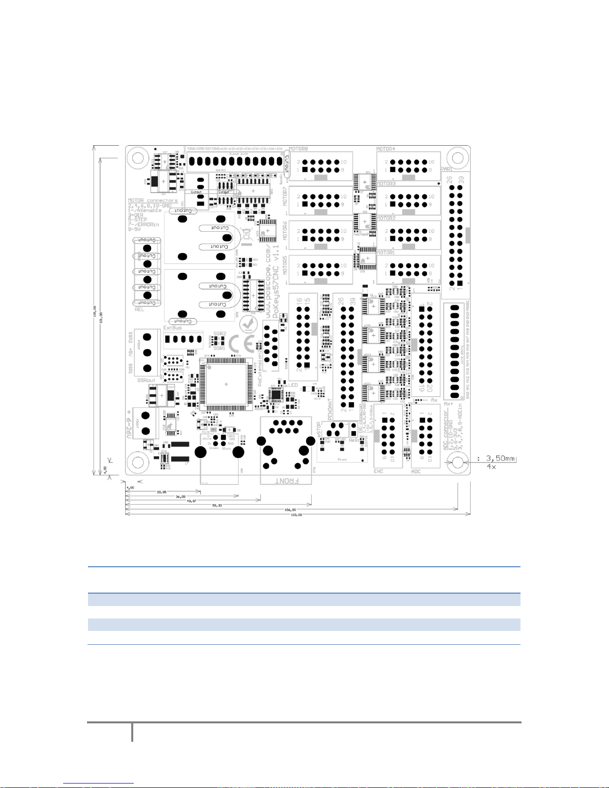
5.1. PoKeys57CNC dimensions
Measurements are in mm.
5.2. Environment specifications
Parameter
Min
Typ
Max
Unit
Power supply range
6 - 26 V Operating temperature
0 - 60
°C
Storage temperature
-40 - 85
°C
Humidity
5 - 95 (non-condensing)
% RH
PoKeys user manual
24
www.poscope.com
6. Installation
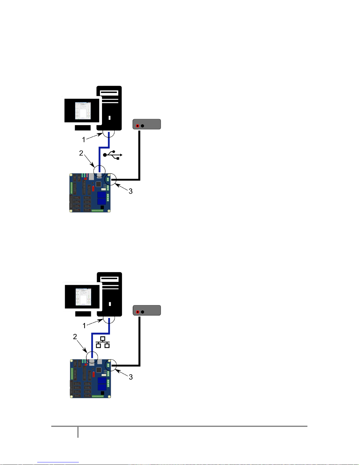
6.1. Using USB
PoKeys57CNC is a USB 1.1/2.0 compliant device.
Step 1: Locate a free USB 2.0 port on your
computer (1) and PoKeys57CNC board (2) and
connect them with a standard USB cable.
Step 2: Connect the PoKeys57CNC board to an
appropriate power supply (3).
Step 3: Install PoKeys software
Step 4: Open PoKeys application, connect to
your PoKeys57CNC device and enable Fast USB
interface (go to Settings > Enable Fast USB
interface).
Step 5: Remove the USB cable from
PoKeys57CNC device and insert it again. The
computer will find a new device and search for
drivers. See FAQ section of the manual if driver
installation fails.
6.2. Using Ethernet - direct connection between PoKeys57CNC and computer
Network firewalls must allow all traffic on TCP/UDP port 20055 between PoKeys57CNC device and
PoKeys-related software running on a computer.
Step 1: Locate ethernet ports on your computer
(1) and PoKeys57CNC board (2) and connect
them with RJ-45 cable (standard network cable).
Step 2: Connect the PoKeys57CNC board to an
appropriate power supply (3).
Step 3: Configure your computer's network card
with a static IP address in the 192.168.x.x range
Step 4: Install PoKeys software
Step 5: Start PoKeys software, select the
PoKeys57CNC device in the list and click on
'Configure' button. Select the unique IP address
for the PoKeys57CNC device in the same range as
the computer's network card
PoKeys user manual
25
www.poscope.com
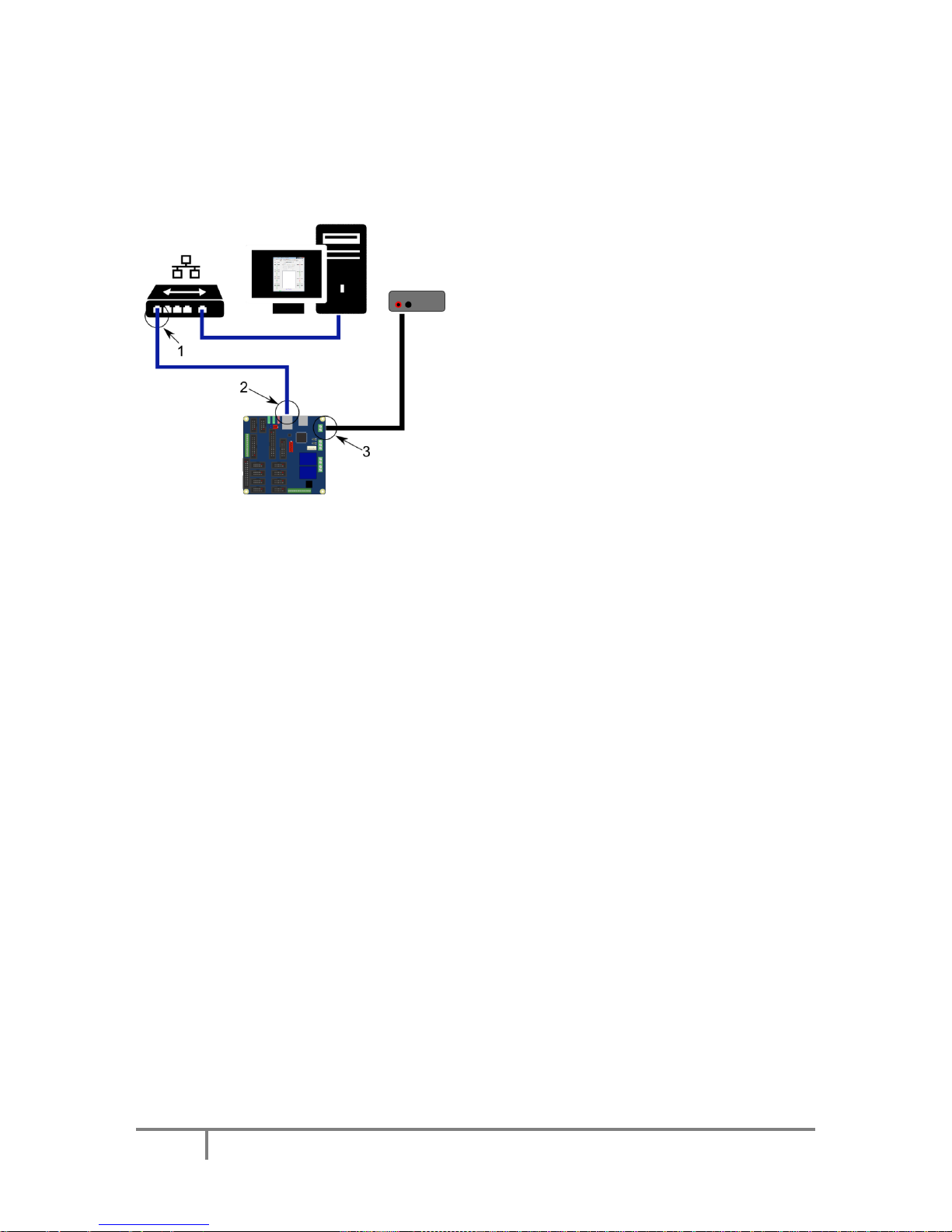
6.3. Using Ethernet - PoKeys57CNC connected to a network with DHCP server
Network firewalls must allow all traffic on TCP/UDP port 20055 between PoKeys57CNC device and
PoKeys-related software running on a computer.
Step 1: Locate ethernet ports on your router (1)
and PoKeys57CNC board (2) and connect them
with RJ-45 cable (standard network cable).
Step 2: Connect the PoKeys57CNC board to an
appropriate power supply (3).
Step 3: Install PoKeys software
6.1. Using USB and Ethernet
PoKeys57CNC device can also be connected to computer by using both the USB and Ethernet
connection. In this case, applications will detect two instances of PoKeys57CNC devices and USB
connection will be selected by default by third-party applications.
Follow the above instructions on connecting the PoKeys57CNC device over Ethernet and USB.
6.2. Motor drivers and peripherals installation
Connect motor drivers to dedicated 10-pin axis motor connectors, marked as MOTOR1, MOTOR2 …
MOTOR8.
Connect pendant to the dedicated pendant connector.
 Loading...