

PoKeys 56U, 56E, 57E User Manual

PoKeys Pulse engine v2 documentation
Version: 6/3/2016

PoKeys Pulse engine v2 documentation
2
www.poscope.com
SAFETY INFORMATION
This product is intended for integration by the user into a computer numerical control (CNC)
machine. It is the user's responsibility to assess the overall system design and address all safety
considerations that affect the users and equipment. The user assumes all responsibility for system
design, including compliance with regulatory standards and codes issued by the applicable
entities. PoLabs do not make any claims as to the suitability of this equipment for the user’s
application. Serious personal injury or equipment damage can occur from the improper integration,
installation or operation of this product.
This product is not guaranteed to be fail-safe. The system that this equipment is used with shall be
fitted with a separate means of fail-safe protection, emergency-stop capability and/or system power
removal. This equipment may be connected to dangerous power sources, including electrical power
sources. Dangerous voltage levels may be present at this equipment or at connected devices.
Measures must be taken to prevent persons from contacting voltage sources which may be present.
Equipment should be housed inside an enclosure suitable for the intended environment. Safety
interlocks should be provided to prevent any and all dangers to personnel.
CNC machine tools are inherently dangerous, and can cause injury to operators and maintenance
personnel. Operators and maintenance personnel shall be properly trained in the safe use, operation
and maintenance of such machines. Automated machines that this equipment may be used with can
move at any time. All persons exposed to such machines must understand the dangers that are
present.
!

PoKeys Pulse engine v2 documentation
3
www.poscope.com
Description
PoKeys Pulse engine v2 (upgrade of the original PoKeys Pulse engine) is available on PoKeys56U,
PoKeys56E and PoKeys57E devices and enables a direct control of a positioning systems that accepts
step/direction signals (stepper motors, servo systems, etc.). PoKeys Pulse engine can operate in
standalone (rapid positioning and speed control mode, homing, probing) or in slave mode (under the
commands of the PC application). Each axis supports two end (limit) switch inputs, one home
(reference position) switch input, which can be either a dedicated one or shared with limit switch
inputs. All inputs can are fully configurable (input polarity, placement) using the PoKeys protocol
(used by PoKeys application or a third party application for motion control).
In addition, operations in each axis can be limited using the soft limit function, where minimum and
maximum permissible axis position is specified - once enabled, the axis is put to a stop when
exceeding the allowed range, but is free to move in other direction.
Each axis can be assigned a different encoder with a customizable multiplication factor for the
operation with MPG (manual pulse generator).
PoKeys Pulse engine also supports a dedicated emergency switch input, which stops the pulse
generation.
Figure 1: PoKeys Pulse engine connections for use with the integrated pulse generator

PoKeys Pulse engine v2 documentation
4
www.poscope.com
Table of contents
Description .............................................................................................................................................. 3
Pulse generator selection .................................................................................................................... 6
PoKeys device pins in use ........................................................................................................................ 7
Integrated pulse generator - up to 3 axes at 25 kHz step frequency .................................................. 7
External pulse generator with dedicated IO capability - up to 8 axes at 125 kHz step frequency ..... 8
10-pin motor driver connector pinout ............................................................................................ 9
Dedicated axis switch inputs ........................................................................................................... 9
Relay outputs ................................................................................................................................... 9
Open-collector outputs ................................................................................................................. 10
0-10 V voltage output .................................................................................................................... 10
Additional digital inputs ................................................................................................................ 10
Pulse engine limitations: ....................................................................................................................... 11
PoKeys Mach3 plugin ............................................................................................................................ 12
Installing plugin ............................................................................................................................. 12
PoKeys Mach3 plugin existing functionality .................................................................................. 12
Configuring plugin for the first time .............................................................................................. 12
Enabling Pulse engine .................................................................................................................... 14
Motors/axis setup ......................................................................................................................... 15
Axis switches configuration ........................................................................................................... 17
Setting up digital inputs and outputs mapping ............................................................................. 18
Pendant mode ........................................................................................................................... 19
PoPendant configuration ....................................................................................................... 20
Encoder (MPG) settings ................................................................................................................. 21
MPG (manual pulse generator) setup ....................................................................................... 21
PoKeys IO status ............................................................................................................................ 26
Other (miscellaneous) settings ...................................................................................................... 26
Reading and writing of IO from VB script ...................................................................................... 27
Example script (finds the PoKeys device with the serial number 25000, then toggles the IO 1
on and off at a rate of 1 Hz): ..................................................................................................... 28
Additional OEM buttons ................................................................................................................ 29
Additional OEM LEDs ..................................................................................................................... 29
Pulse engine v2 operating principles..................................................................................................... 30
Modes of operation ........................................................................................................................... 31

PoKeys Pulse engine v2 documentation
5
www.poscope.com
Safety charge-pump output .............................................................................................................. 32
Motor driver enable outputs ............................................................................................................. 32
Axis parameters ................................................................................................................................. 32
Custom external pulse generator without IO functionality .............................................................. 32
Frequently asked questions .................................................................................................................. 35

PoKeys Pulse engine v2 documentation
6
www.poscope.com
Pulse generator selection
Pulse engine supports different pulse generators:
- Integrated pulse generator (for up to 3 stepper motors with step frequencies up to 25 kHz)
- External pulse generator without dedicated IO capabilities (for up to 8 stepper motors with
step frequencies up to 125 kHz) using PoExtensionOC16 or third-party custom board.
- External pulse generator with dedicated IO capabilities (for up to 8 stepper motors with step
frequencies up to 125 kHz, dedicated limit+, limit-, home/ref, axis error inputs, 3 relay
outputs, 4 open-collector outputs, 0-10 V output) using PoKeysCNCaddon (pictured below).
PoKeysCNCaddon inputs and outputs are galvanically isolated from PoKeys board.
Figure 2: PoKeysCNCaddon v1.0
PoKeys Pulse engine v2 documentation
7
www.poscope.com
PoKeys device pins in use
Integrated pulse generator - up to 3 axes at 25 kHz step frequency
Pin
Function
38
Direction output – x
39
Direction output – y
40
Direction output – z
46 !
Step output – x
48 !
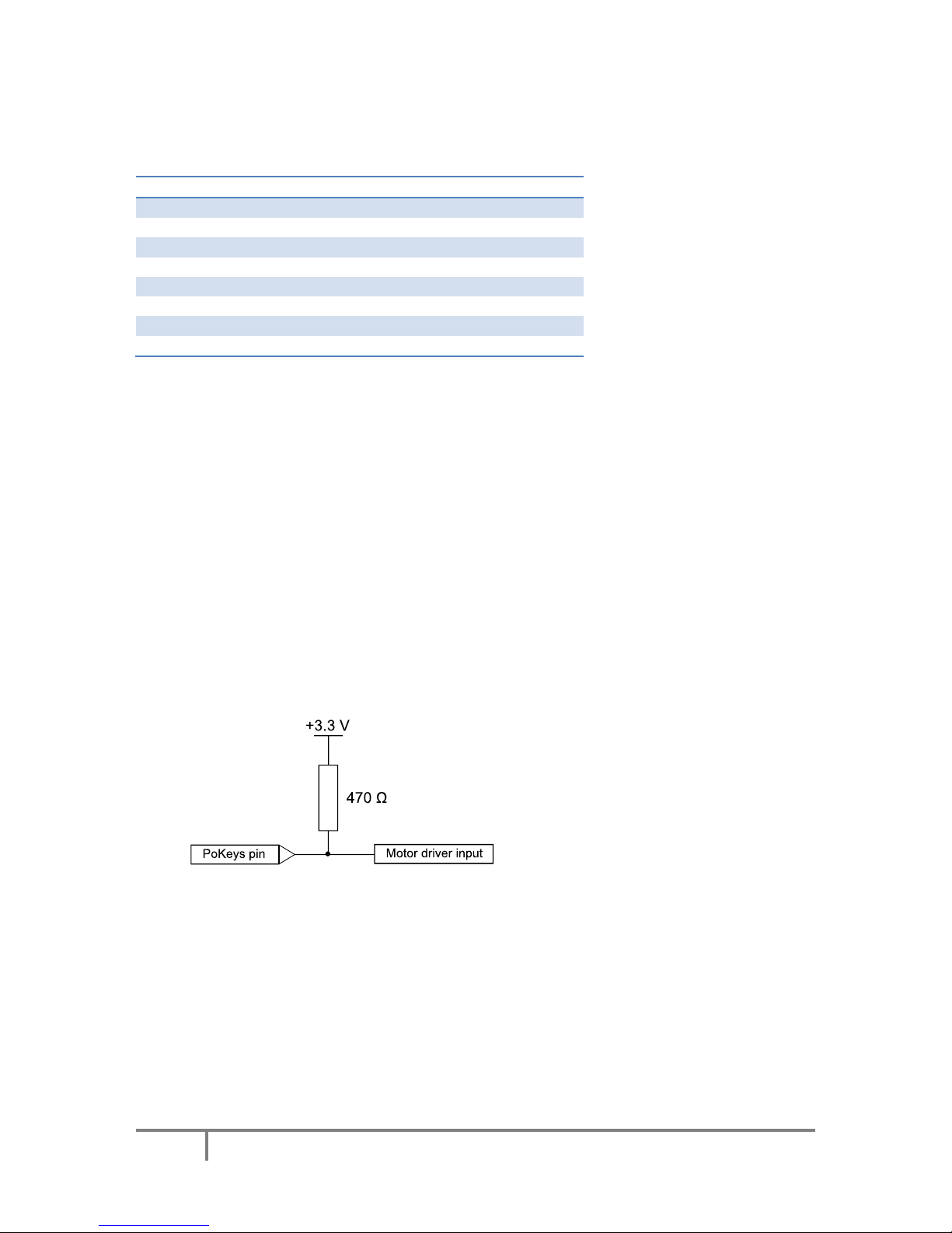
Step output – y (external 470 Ω pull-up resistor required)
49 !
Step output – z (external 470 Ω pull-up resistor needed)
52
Emergency switch input
53
Safety charge pump 5 kHz output
Inputs for limit, home and probing switches can be freely connected to any PoKeys pin and
configured in software.
Remarks:
- Watch for pin 47! It is not used for step output!
- All switch inputs expect normally closed (NC) switches and must be connected between
specified PoKeys input pin and ground.
- We advise adding an additional 1 kΩ pull-up resistor on pins with an external switch
- Emergency switch must be connected in such way so that it cuts the power supply to the
motors when the switch is activated.
External pull-up resistor wiring for pins 48 and 49

PoKeys Pulse engine v2 documentation
8
www.poscope.com
External pulse generator with dedicated IO capability - up to 8 axes at 125
kHz step frequency1
Please pay attention to connecting the PoKeysCNCaddon to PoKeys device. PoKeysCNCaddon
connects to PoKeys using the Expansion port flat cable, attached to the board. The Expansion port
signals should be connected to PoKeys as follows:
Pin
Description
PoKeys56U
pin
PoKeys56E/57E
pin
1
(red)
5 V power supply to the PoKeysCNCaddon - must supply at
least 400 mA for correct operation
5 V
5 V
2
PoKeys ground (not to be used for PoKeysCNCaddon IO)
GND
GND
3
PWM signal for 0-10 V output
17-22
17-22
4
Signal for IO capabilities (output)
38
38
5
Signal for IO capabilities (output)
37
37
6
Signal for IO capabilities (output)
36
36
7
Signal for IO capabilities (input)
35
35
8
Signal for pulse generation
23
9
9
Signal for pulse generation
25
11
10
Signal for pulse generation
26
51
1
Note that PoKeys Mach3 plugin supports only 4 axes
10-pin connections to motor drivers
PoExtension
connector
3 NO relay contacts
8x
LimitHome/Ref
Limit+
signals
4 OC outputs, 0-10 V output, Spindle error, GND
Vmax adjustment
3 additional digital inputs
Red = galvanically
connected to
PoKeys
PoKeys Pulse engine v2 documentation
9
www.poscope.com
10-pin motor driver connector pinout
Dedicated axis switch inputs
All inputs have built-in pull-up resistor - switches must be connected between GND (on the
PoKeysCNCaddon) and the correspoding input. Select 'Dedicated pin' in the axis settings.
Pin (from
top to
bottom)
Function
Pin
(continued
)
Function
-AX8
Limit- for axis 8
-AX4
Limit- for axis 4
RefAX8
Ref/home for axis 8
RefAX4
Ref/home for axis 4
+AX8
Limit+ for axis 8
+AX4
Limit+ for axis 4
-AX7
Limit- for axis 7
-AX3
Limit- for axis 3
RefAX7
Ref/home for axis 7
RefAX3
Ref/home for axis 3
+AX7
Limit+ for axis 7
+AX3
Limit+ for axis 3
-AX6
Limit- for axis 6
-AX2
Limit- for axis 2
RefAX6
Ref/home for axis 6
RefAX2
Ref/home for axis 2
+AX6
Limit+ for axis 6
+AX2
Limit+ for axis 2
-AX5
Limit- for axis 5
-AX1
Limit- for axis 1
RefAX5
Ref/home for axis 5
RefAX1
Ref/home for axis 1
+AX5
Limit+ for axis 5
+AX1
Limit+ for axis 1
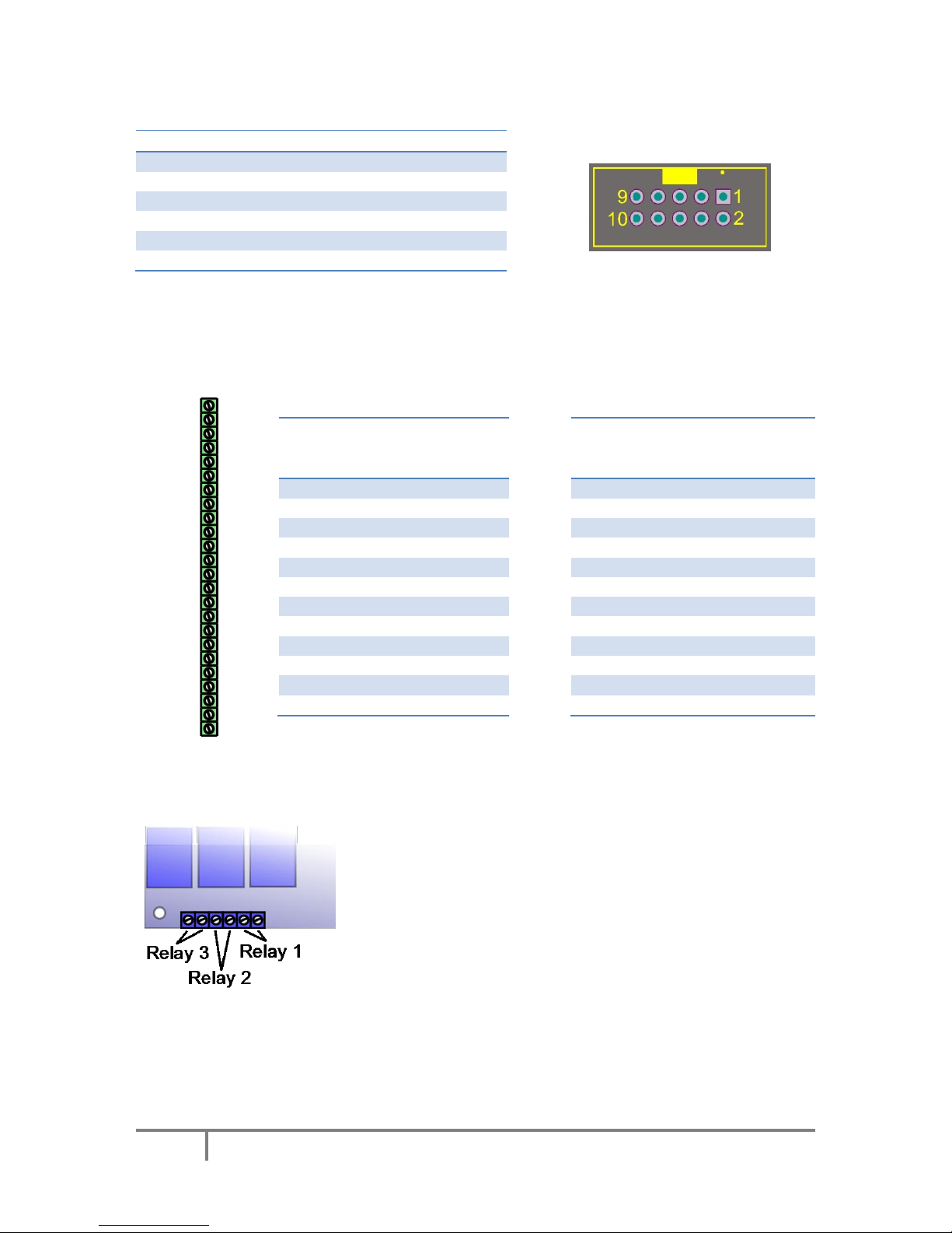
Relay outputs
PoKeysCNCaddon board features 3 relay outputs with normally-open
contacts.
Rating:
- max. 7A/240VAC, max. 10A/125VAC or max. 10A/28VDC.
-AX8
+AX8
-AX7
+AX7
-AX6
+AX6
-AX5
+AX5
-AX4
+AX4
-AX3
+AX3
-AX2
+AX2
-AX1
RefAX1
+AX2
Pin
Function
1
Axis enable output
3
Direction output
5
Step output
7
Error input
2, 4, 6, 8, 10
GND
9
Not connected
PoKeys Pulse engine v2 documentation
10
www.poscope.com
Open-collector outputs
PoKeysCNCaddon board features 4 open-collector outputs with LEDs for signaling the output state.
Rating:
- Maximum applied voltage: 80 V
- Maximum DC current: up to 50 mA
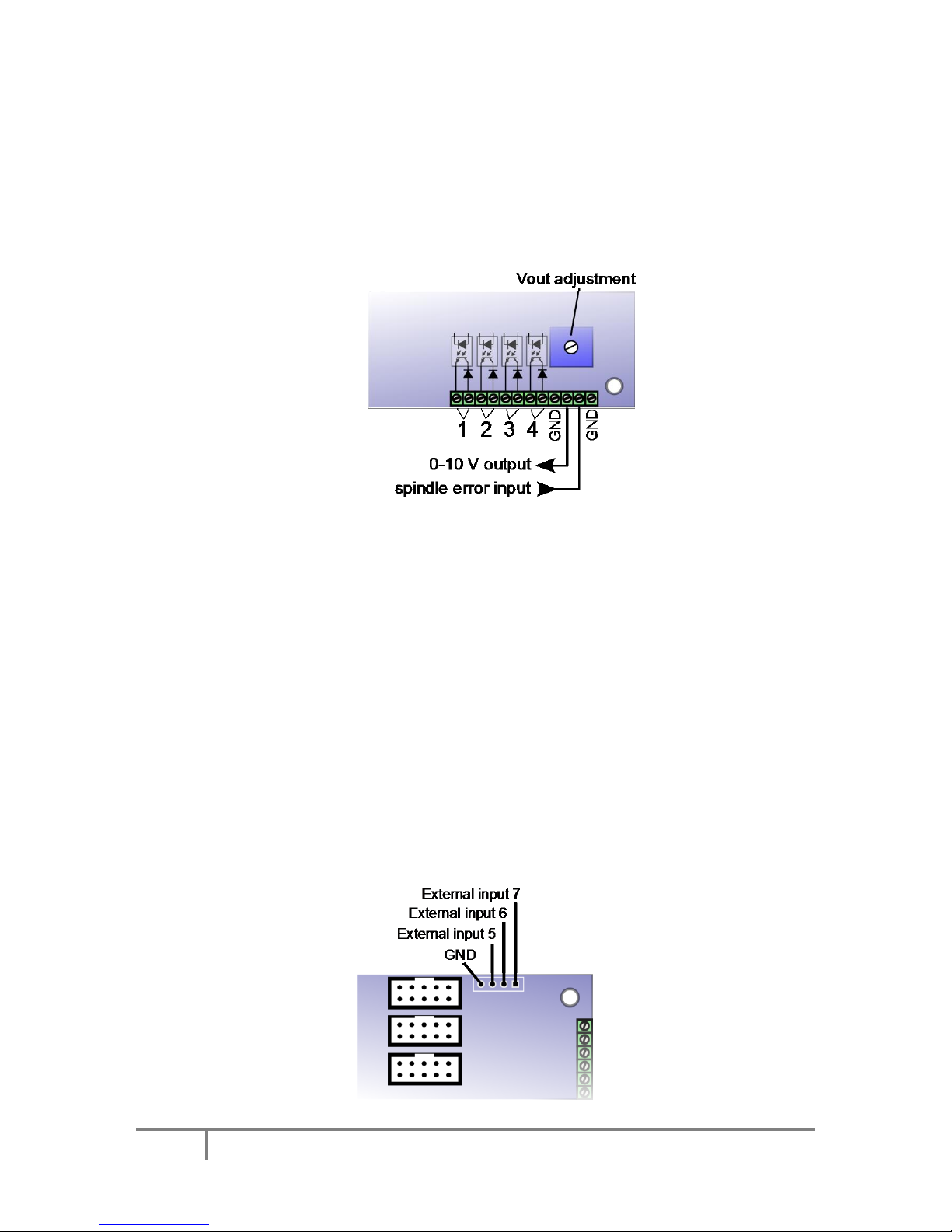
0-10 V voltage output
PWM signal is used to create the 0-10 V voltage output. PWM signal with 0% duty cycle produces 0 V
on output, while 100% duty cycle produces Vmax on output. Vmax can be adjusted using the
potentiometer 'Vout'.
In order to convert PWM signal to an analog output, a low-pass filter with the time constant of 1 ms
is applied to the source signal. In order to avoid ripples in the analog output, use PWM frequency of
10 kHz or more.
Setup/calibration: either set the duty cycle to 100% or connect the PWM signal input to
PoKeysCNCaddon board (pin 3) to +3.3V. Use the multimeter to measure voltage between GND adn
0-10 V output. Use the Vout adjustment potentiometer to adjust the voltage to 10 V (
Additional digital inputs
There are 4 additional digital inputs: spindle error input and 3 general purpose external digital inputs,
available on the top right corner of the PoKeysCNCaddon board.

PoKeys Pulse engine v2 documentation
11
www.poscope.com
Pulse engine limitations:
- Minimum/maximum position:
o Internal motion controller: -/+ ~16.8 million ticks
o External (buffered) mode: -/+ ~2100 million ticks
 Loading...