

Page 1

LINK MANAGER
Manual
Version 1.5 – 12/5/2014
TM
Point Six, Inc. | 161 Prosperous Place | Suite 200 | Lexington, KY 40509
(859) 266-3606 | sales@pointsix.com | support@pointsix.com | www.pointsix.com
© 2014 Point Six, Inc. All rights reserved.
Page 2

Page 3

Contents
Introduction 5
Overview ............................................................................................................................. 5
Over the Air Sensor Data Collection ..................................................................................... 5
Link Manager Sensor Virtualization...................................................................................... 5
Link Manager Notes ............................................................................................................. 6
Quick Start Setup 8
Steps ................................................................................................ .................................... 8
Connecting the Link Manager 11
Overview: Connecting ........................................................................................................ 11
Ethernet – TCP/IP .............................................................................................................. 12
Serial Port .......................................................................................................................... 14
RS-485 Port........................................................................................................................ 14
Set Up Your Sensor Using the Point Sensor Utility. ................................................. 8
Connecting the Link Manager ................................................................................. 9
Set Up Your Link Manager. ................................................................ .................... 9
LAN Connection................................................................................................... 12
Direct to PC .......................................................................................................... 13
Browser ................................................................................................................ 13
Point Sensor Utility 15
Overview ........................................................................................................................... 15
Set Up Point Sensor Utility ................................................................................................. 15
Point Sensor Utility Usage .................................................................................................. 16
Advanced Setup ................................................................................................................. 16
User Interface 18
Overview ........................................................................................................................... 18
Main Menu......................................................................................................................... 18
I/O Status ........................................................................................................................... 19
Sensor Setup ...................................................................................................................... 20
Setup Menu ........................................................................................................................ 20
Manager Setup ................................................................................................................... 21
Communications Setup ....................................................................................................... 22
Set Manager’s Clock .......................................................................................................... 23
Automatic Time Update...................................................................................................... 23
Passwords Setup ................................................................................................................. 24
Activity Log ....................................................................................................................... 25
Usage Notes 26
Link Manager Manual Contents i
Page 4

Notes.................................................................................................................................. 26
Development Notes 28
Overview ........................................................................................................................... 28
“I Am Here Packet” ............................................................................................................ 28
Common Software Tools 30
Software ............................................................................................................................. 30
Discover Utility .................................................................................................... 30
PC Utilities and Tools ........................................................................................... 30
Link Manager Advanced Functions 31
Current I/O Readings .......................................................................................................... 31
Pass-Thru Mode ................................................................................................................. 31
Repeater Mode ................................................................................................................... 35
Support Functions .............................................................................................................. 36
Discovery ............................................................................................................. 36
DHCP ................................................................................................................... 36
Factory Reset ........................................................................................................ 36
Communicating with the Link Manager 38
Link Manager Protocol ....................................................................................................... 38
CRC16 Algorithm ................................................................................................. 39
Example C function .............................................................................................. 40
General information............................................................................................................ 41
Sensors ................................ ................................................................................. 41
Command Overview ........................................................................................................... 43
Command Syntax ................................................................................................. 43
Time representations ............................................................................................. 43
Future Compatibility ............................................................................................. 44
Command Outline .............................................................................................................. 45
Commands 47
A’ - Auto Add Mode command.......................................................................................... 47
‘C’ – Notify Setup .............................................................................................................. 51
‘CC’ – Configure/Read Clock ............................................................................................. 52
‘CCN’ – Configure Automatic Time Update ....................................................................... 54
‘CD’ – Configure/Read Link Manager Identification Label ................................................. 55
‘CI’- Configure/Read Link Manager Static IP Address ........................................................ 56
‘CID’- Configure DHCP ..................................................................................................... 58
‘CIP’- Configure TCP/IP Ports ........................................................................................... 59
‘CPD’ & ‘CPC’ – Configure Login Passwords .................................................................... 60
‘CR’ - Configure Radio ..................................................................................................... 61
‘CS’ - Configure/Read Sensor Setup .................................................................................. 63
Sensor I/O Point Setup .......................................................................................... 64
‘CT’ – Configure Media Ports............................................................................................. 69
‘CTB’ – Set Simple Protocol .............................................................................................. 70
‘CTC’ – Enable Command Processor .................................................................................. 71
‘CTF’ – Set CRC16 Protocol .............................................................................................. 72
‘CTP’ – Set CRC16 Protocol Direct .................................................................................... 73
‘CV’ – Configure/Read Enumerated Engineering Unit Table ............................................... 75
‘CX’ - Set Media Repeater Modes ..................................................................................... 77
ii Contents Link Manager Manual
Page 5

‘CYD’ – Configure UPD Pass-Thru Destinations ................................................................ 79
‘CYP’ – Configure UDP Pass-Thru Parameters and Discovery ............................................ 81
‘D’ - Get Last Data command ............................................................................................ 83
‘EC’ – Clear Activity Log ................................................................................................... 86
‘ER’ – Read an Activity Log Record ................................................................................... 87
‘EU’ – Activity Log Usage ................................................................................................. 92
‘IC’ – Information Counts .................................................................................................. 93
‘IIU’ – Information UDP Pass-Thru Destination ................................................................. 94
‘ILR’ – Current Sensor Log State........................................................................................ 95
‘ILT’ – Destination Sensor Table List ................................................................................. 96
‘IM’ – Media Information ................................................................................................... 97
‘IP’ – IP Address Settings ................................................................................................... 98
‘IPS’ – DHCP State Information ................................................................ ......................... 99
‘IT’ – Time Zone Information ........................................................................................... 100
‘ITD’ – Daylight Savings Schedule ................................................................................... 101
‘IU’ – Information Pass-Thru ............................................................................................ 103
‘IV’ – Version Information ............................................................................................... 104
‘IY’ – Information Synchronize the Clock......................................................................... 105
‘L’ – Login/Logout Commands......................................................................................... 106
‘PY’ – Attempt Automatic Time Update ........................................................................... 107
‘S’ - Get Status Data Command ....................................................................................... 108
‘U’ - Set Pass-Thru Mode ................................................................................................ 109
‘UM’ - Set Pass-Thru Mode Direct .................................................................................. 111
‘V’ – Verbose ................................................................................................................... 113
Error Codes 115
Overview ......................................................................................................................... 115
Error Code List ................................................................................................................. 115
Appendix 117
Models ............................................................................................................................. 117
Troubleshooting ............................................................................................................... 117
Sensor Issues ...................................................................................................... 117
Delivery Issues to the Host Application ............................................................... 118
Connection Issues ................................................................ ............................... 118
UDP Packet Formats ........................................................................................................ 119
UDP Discovery Request ..................................................................................... 119
UDP Discovery Response ................................................................................... 119
UDP PassThru & Wifi Sensor UDP Packet......................................................... 120
UDP Host Acknowledgement ............................................................................. 121
UDP Set Destination ........................................................................................... 121
Reset Password ................................................................................................................ 122
Ethernet Firmware Download ................................................................ ........................... 123
Overview ............................................................................................................ 123
Preparation ......................................................................................................... 123
Procedure ........................................................................................................... 123
Specifications ................................................................................................................... 125
Acknowledgements 126
Trademarks ...................................................................................................................... 126
Glossary of Terms 127
Link Manager Manual Contents iii
Page 6

4 Introduction Link Manager Manual
Page 7

Introduction
Overview
The Link Manager is a data server designed to bridge 900 Mhz Point Sensors and a
host application listening on a TCP/IP network using the Extended Point Sensor
Protocol using UDP. The Link Manager collects data from the 900 Mhz Point
Sensors, both the beacon, configuration and the logged data, and maintains an image
of the beacon, configuration and logged data. The Link Manager then makes contact
with a host application using the same UDP protocol as used for the Wifi Point
Sensors and responds to host commands. The Link Manager at this point looks like
a Wifi Point Sensor. The Link Manager can support up to sixty (60) 900 Mhz Point
Sensors.
Over the Air Sensor Data Collection
The Link Manager communicates with the Point Sensor when the sensor sends a
beacon packet. The Link Manager then responds with additional commands
depending on if data log records need to be collected or setup information from the
sensor needs to be gathered. The Link Manager only collects new log records from
the sensor per conversation. The Link Manager collects the setup information when
the sensor indicates its setup has been changed locally (through the Point Sensor
Utility). The Link Manager conversation frequency is dictated by how often the
sensor sends the beacon packet (transmit period). If the Link Manager is holding
setup information sent from the host, the Link Manager will send the setup
information when the next packet is received from the sensor.
Link Manager Sensor Virtualization
The Link Manager will hold the log data and setup information for up to 60 sensors.
When communicating to a host, the Link Manager emulates a Wifi Point Sensor.
The Link Manager will send a sensor beacon packet to the host that starts the
conversation with the host. The Link Manager then responds to requests from the
host. To the host the Link Manager virtualized sensor appears like a Wifi Point
Sensor. The host can send setup information to the Link Manager which will be later
be forwarded to the 900 Mhz sensor.
Link Manager Manual Introduction 5
Page 8

The Link Manager will send a beacon packet to the host when the conversation with
the sensor has been completed. The Link Manager will continue to send a beacon
packet at a regular interval to the host until an acknowledgement response is received
from the host.
Link Manager Notes
Collects data log records and setup information from 900 Mhz Point
Holds data log records and setup information for up to 60 sensors.
Emulates sensors to the host application. Appears to the host application
The sensor needs to be registered with the Link Manager. (Like how
New setup information can be obtained from the sensor (when the setup has
The host can send setup information to the Link Manager. The Link
Sensors.
like up to 60 Wifi Point Sensors.
sensors are registered with Point Managers).
been changed through the Point Sensor Utility).
Manager will forward the setup information to the sensor when the next
beacon packet is sent from the sensor.
Conversations with the host are initiated when the Link Manager’s
conversation with the sensor is finished.
The Link Manager is fully configurable through a web browser. Use the
Discover tool to locate the Link Manager and then use your web browser to
configure the Link Manager and register sensors.
Each sensor has its own radio address based on the serial number. The
Point Sensor Utility is used to set this radio address.
Programmers can use the Link Manager’s command interface to change the
setup and check status.
Link Manager has additional functions link sensor packet PassThru and
radio repeater function.
6 Introduction Link Manager Manual
Page 9

Link Manager Manual 7
Page 10
Quick Start Setup
Steps
Set Up Your Sensor Using the Point Sensor Utility.
1. Point Sensor Utility Setup:
a. Make sure the following line is set in the PointSensorUtility.INI
file in the section called [Settings]:
“XSCSerializeAddressEnable=1”.
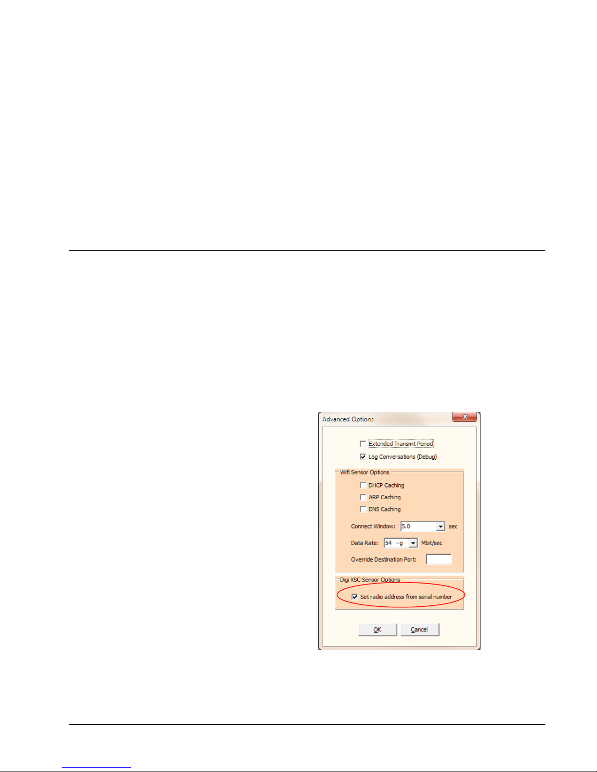
b. In the Advanced Options (from the main menu select the Options /
Advanced Options), make sure the “Set radio address from serial
number” is checked.
8 Quick Start Setup Link Manager Manual
Page 11

c. Set Up the Sensor:
i. Connect the USB Programmer interface to the sensor and
then click the Retrieve button in the Setup tab.
ii. From the Setup tab, set the Transmit Time (ex. 5
minutes), Tries (ex 4) and Log Period (ex 2 minutes).
iii. Click the Update button in the Setup tab to transfer the
settings to the sensor. Remove the USB Programmer
interface from the sensor when finished.
Connecting the Link Manager
1. Connect Antenna. Depending on your specific unit, thread the supplied
antenna(s) to the antenna connector(s) to the Link Manager
2. Connect Ethernet Cable. Connect an RJ-45 cable to the Link Manager and
to your network. Your network must have a DHCP Server that will assign
an IP address to the Link Manager. See the section “Ethernet – TCP/IP”, if
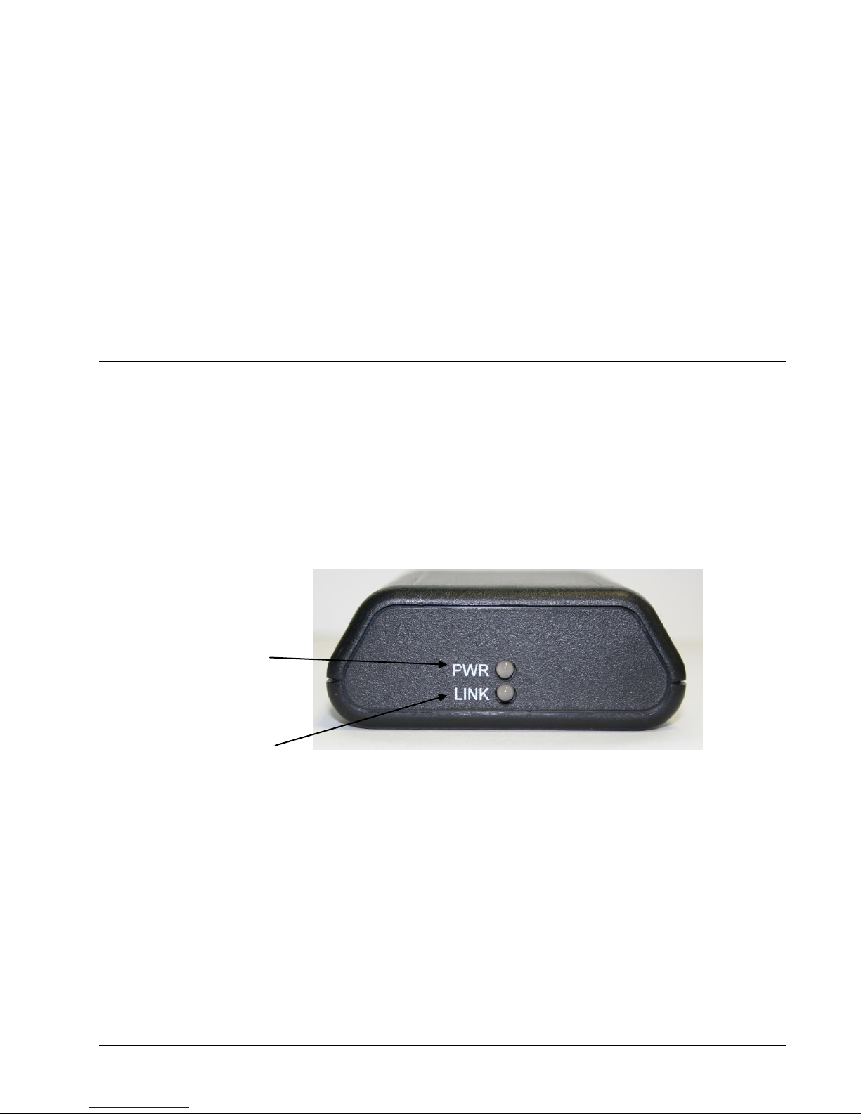
your network does not have a DHCP Server. The green light will light if
there is an active Ethernet connection.
3. Connect the Power Supply. Connect the provided power supply to the Link
Manager. When power is applied, the Link Manager will turn on the red
power light. The red light indicates that the Link Manager is functioning.
It may take a few seconds before the power light is turned on. The Link
Manager also uses the red power light to indicate reception of a packet from
a Point sensor. The Link Manager will blink the red light momentarily
indicating a packet has been received and processed.
4. Run the Discover program to find the Link Manager on your network. Run
the Discover program from a computer that is on the same subnet as the
Link Manager.
5. From the Discover program, double click the Link Manager entry to bring
up the Link Manager web page.
Set Up Your Link Manager.
1. At the Link Manager’s web page, select the Setup menu option and then
select the Manager Setup menu option.
2. Enter a name for a Link Manager.
3. In the Add Sensors field, select “Service Mode for 20 minutes”.
4. Enter a Destination Address. This is the address of the computer running
the host application. The address can be an IP address or a hostname.
5. Click the Submit button to save and apply the settings.
Register the Sensors With the Link Manager.
1. Navigate to the Link Manager I/O Status page.
2. Press the service button (or use magnet) on the Sensor.
3. Wait up to 15 seconds or press Refresh on you browser. The Sensor will be
listed in the I/O Status page. If you click on the default name of the sensor,
Link Manager Manual Quick Start Setup 9
Page 12

the Link Manager will present you a screen to change the sensor name. The
Link Manager will start collecting the sensor’s log data. This may take up
to 2 minutes to complete. Additional sensors can be registered after the
sensor’s log data is collected.
4. Press the service button on the sensor and examine the host application to
determine the Link Manager is sending sensor data to the host application.
If the sensor’s log buffer is full, it will take a few minutes for the Link
Manager to collect all the sensor data before sending to the host application.
You view the progress of the collection from the I/O Status page.
10 Quick Start Setup Link Manager Manual
Page 13
Connecting the Link Manager
Ethernet Link
Power & Activity
Overview: Connecting
The Link Manager has four communication ports: Ethernet-TCP/IP, built-in 900/2.4
Mhz/Ghz Radio an RS232 serial port and an RS485 port. The Link Manager will
respond to commands or receive sensor packets on all ports Before using the Link
Manager, you should carefully evaluate the communication resources available at the
site where the Link Manager will be installed. Typically just the Ethernet and 900
Mhz ports are used.
Link Manager Manual Connecting the Link Manager 11
Page 14
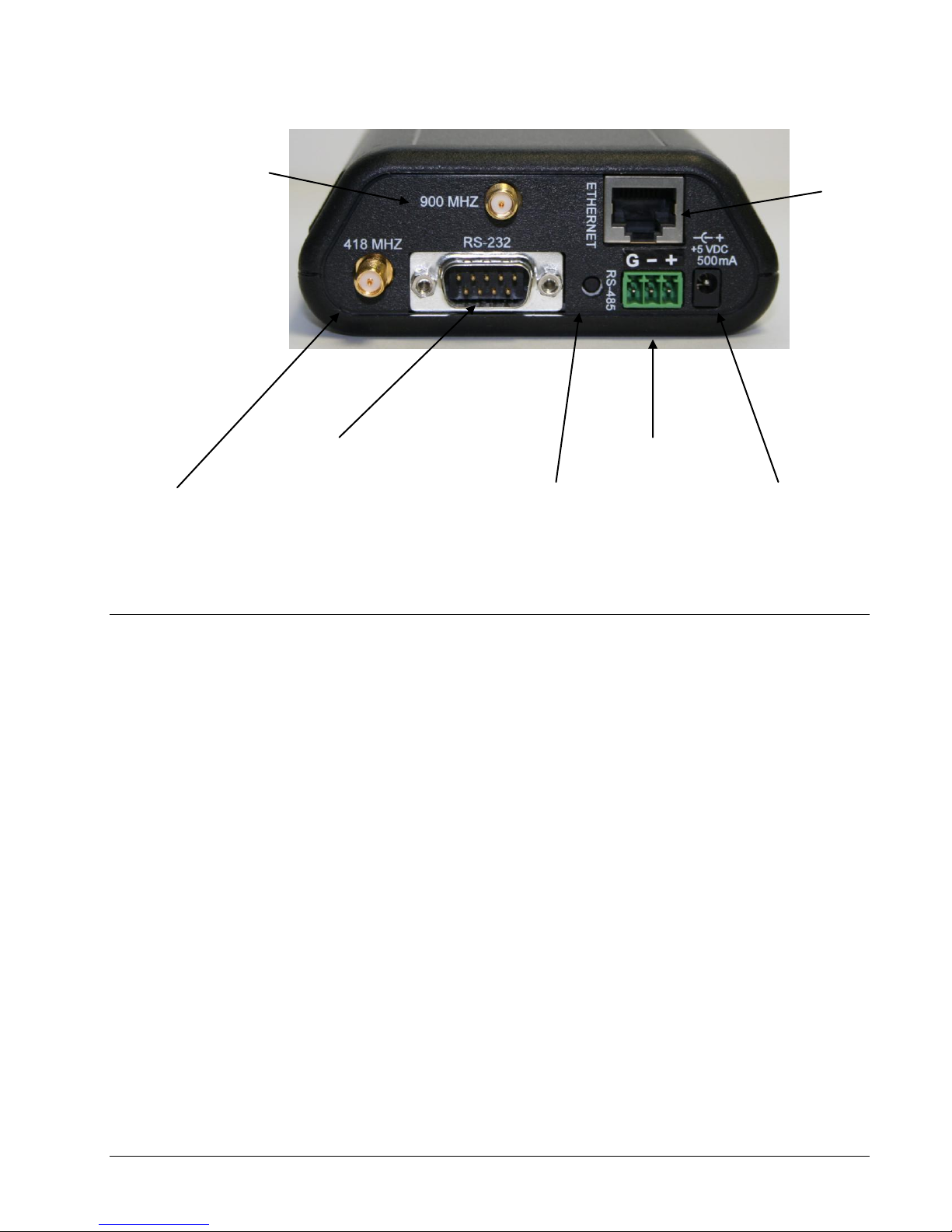
Power Connection
Ethernet Port
Serial Port
Reset
418/433 Mhz Receiver
900 Mhz/2.4 Tranceiver
RS-485 Port
Ethernet – TCP/IP
LAN Connection
Check with your network administer before connecting the Link Manager to a
LAN.
Dynamic IP Address
By default the Link Manager is capable of being assigned an IP address
automatically by the network if the network has a DHCP Server. Connect the Link
Manager using a straight through Ethernet cable to the LAN. Connect power to the
Link Manager. If the ‘Ethernet Link’ light is on, then the Link Manager is connected
physically and electrically to the LAN.
The next task is to obtain the IP address assigned to the Link Manager. Run the
Discover utility that came with your Link Manager (or obtain the utility from your
dealer). Using the Discover utility, note the IP address for this Link Manager. To
view the Link Manager's web page using the Discover tool, right click over the Link
Manager entry and then select "Browse" from the pop menu. The Discover utility
will start the browser and point it to the Link Manager's web page.
Another method to finding the IP address is to connect via the serial port with your
PC. Follow the instructions as described in the section that follows called "Serial
Ports" and issue the "IP" command.
12 Connecting the Link Manager Link Manager Manual
Page 15

Static IP Address
In order for the Link Manager to communicate TCP/IP, it needs an IP address,
network mask, and possibly a gateway address. You may need to consult with your
network administrator to determine these parameters. Chances are you will have to
change the Link Manager’s default IP address: IP address 192.168.1.55, network
mask 255.255.255.0, no gateway address and port 1000 and turn off dynamic IP
address mode. You can change these settings using the "CIDS" and “CIS”
commands through any of the communications ports. If you need to use the Ethernet
port to change these settings see the next section “Direct to PC”.
Example
Command: <^B>CIDSF,F<CR>
Response: <^B>CIDSF<CR>
Remarks: turn off dynamic IP mode.
Command: <^B>CIS192.168.1.46,255.255.255.0,192.168.1.200<CR>
Response: <^B>CIS192.168.1.46<CR>
Remarks: set IP address to “192.168.1.46”, subnet mask
to”255.255.255.0” and gateway to “192.168.1.200“.
<^B> is STX (02H). Press Ctrl and B using a terminal emulation program.
<CR> is 0DH. Press Enter using a terminal emulation program.
Connect your Link Manager through its Ethernet port to the LAN with a standard
(non-crossover) Ethernet cable. The ‘Ethernet Link’ light will turn on indicating a
valid Ethernet physical connection. To test if the connection is valid and the Link
Manager is set up properly, use the Ping utility on your computer and ping the Link
Manager’s IP address. Use your Internet browser to view the Link Manager web
page. You can also use the Discover tool to locate the Link Manager if you do not
know its IP address.
Direct to PC
The Link Manager can be connected directly to a computer through the Ethernet port
by a network cable. You may need to change the TCP/IP settings on your PC and/or
the settings in the Link Manager. If the Link Manager's address cannot be
automatically assigned, the Link Manager will default to address 192.168.1.55,
subnet mask of 255.255.255.0 and port 1000. You will need to set the computer’s
address to an address on the Link Manager’s subnet or change the Link Manager’s
address to match the computer’s subnet mask. To change the IP settings on a
computer running the Windows operating system, follow these steps: select the
following ‘Control Panel -> Network -> TCP/IP’; select the TCP/IP service for your
network card; choose ‘Properties->IP Address’; choose ‘Specify an IP Address’
(example: 192.168.1.40 255.255.255.0); and fill in the initial values for subnet
mask and IP address. View the LAN connection status or run IPCONFIG to verify
changes. When finished changing the IP address and connecting the computer to the
Link Manager, use the Ping utility on your computer and ping the Link Manager to
verify your settings and connection. Use your Internet browser to view the Link
Manager web page.
Note: If your Link Manager has been assigned a dynamic IP address on a previous
network and then is moved to a network that does not have a DHCP server, it will
remain at the last assigned IP address, not revert back to 192.168.1.55.
Browser
Once you have your Link Manager connected and configured for TCP/IP
communications, start the browser on your computer and enter the Link Manager’s
IP address where you would normally enter an URL (Ex. Address: 192.168.1.55). If
Link Manager Manual Connecting the Link Manager 13
Page 16

Pin
Description
RX+
+ communication signal
RX-
- communication signal
Gnd
Ground
PWR
Optional output power to power sensors.
9 Volts DC, 100 milliamps maximum
Serial Port
RS-485 Port
you have successfully made the connection, your browser should show the title
“Link Manager” and a header row for the sensor table with no sensors.
The Link Manager has an external serial port so it can be connected to receiver or a
PC. The serial port can receive packet information from a receiver or receive
commands and send responses. The serial port is an RS232 DTE device and
requires a NULL modem cable to connect to a computer. Link Manager uses RS232
communication parameters of 19200 baud, 8 data bits, 1 stop bit and no parity.
The Link Manager does not use RS232 handshaking lines. If connecting to a PC
through a NULL modem, it is best to turn off handshaking mode in your
communication program.
The RS-485 Port is used to connect RS-485 wired sensors (2 wire). These sensors
can be multi-dropped (more than one sensor connected to the RS485 port). Link
Manager provides optional power through the RS485 connector. The
communication parameters for the port are 19200 baud, 8 data bits, 1 stop bit and
no parity. The following shows the connector pin out:
Commands can be sent and response received through the RS-485 port using the
CRC16 protocol.
14 Connecting the Link Manager Link Manager Manual
Page 17

Point Sensor Utility
Overview
The sensor must be configured in order to be used with the Link Manager. The Point
Sensor Utility is used to configure the sensor.
Set Up Point Sensor Utility
Point Sensors must use a special addressing mode for use with the Link Manager.
The Point Sensor Utility must be set up to configure the sensor to use the addressing
mode.
In the Point Sensor Utility’s setup file, add the following settings paramter to enable
the special addressing mode. In the Point Sensor Utility , go to the Help menu and
then select “Utility Folder Paths” and then “Explore Setup”. The utility will open a
text editor showing the Point Sensor Utility settings. Add the line
“XSCSerializeAddressEnable=1” to the [Settings] section. Here is an example:
[Settings]
QuickHelp=0
DebugLog=1
XmitPeriodOverride=0
DHCPCache=0
ARPCache=0
DNSCache=0
ConnectWindow=5.0
WLanRate=15
DestPortOverride=0
XSCSerializeAddressEnable=1
Save the changes and then restart the Point Sensor Utility.
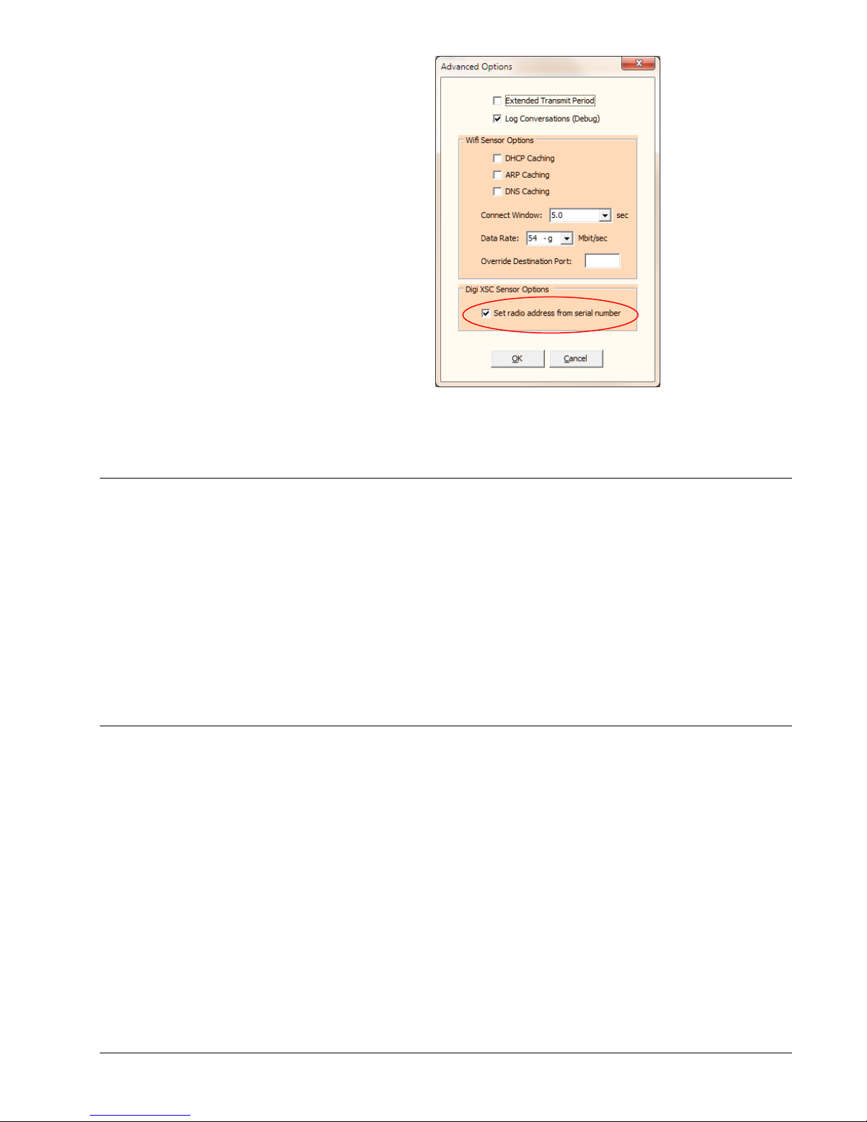
Go to the Advanced Options Window (from the main menu select “Options” and
then “Advanced Options”) and check the box “Set radio address from serial number”
and click OK
Link Manager Manual Point Sensor Utility 15
Page 18
Set the utility to use the Digi XBee 900 radio. From the main menu, select Options
and Radio Type. Select “Digi Xbee 900/2.4”.
Point Sensor Utility Usage
Advanced Setup
Connect the USB Programming interface into the sensor and then from the Setup tab
click on the Retrieve button to retrieve the sensor’s settings.
From the Setup tab, set the Transmit Period, Tries, Logging Period, Alarms and the
ID Info.
Click the Update button (in the Setup tab) to update the sensor with the latest settings
and also set the special addressing mode for the sensor radio.
Disconnect the USB Programming interface. The sensor is now ready to be used
with a Link Manager.
You may need to set the Point Sensor to use another radio Hop Table under the
following circumstances:
1. Having interference issues using the default Hop Table (3).
2. Have more than one Link Manager within radio range and want to isolate
the radio networks between Link Managers.
To change the Hop Table number, in the Point Sensor Utility , go to the Help menu
and then select “Utility Folder Paths” and then “Explore Setup”. The utility will
open a text editor showing the Point Sensor Utility settings. Add the line
“XSCSNHopTable=n” to the [Settings] section where “n” is a number from 0 to 6.
Here is an example:
16 Point Sensor Utility Link Manager Manual
Page 19

[Settings]
QuickHelp=0
DebugLog=1
XmitPeriodOverride=0
DHCPCache=0
ARPCache=0
DNSCache=0
ConnectWindow=5.0
WLanRate=15
DestPortOverride=0
XSCSerializeAddress=1
XSCSerializeAddressEnable=1
XSCSNHopTable=6
Save the changes and then restart the Point Sensor Utility.
The Link Manager must be set to the same Hop Table.
Link Manager Manual Point Sensor Utility 17
Page 20

User Interface
Overview
From the Link Manager web pages, the Link Manager can be configured to manage
sensors and send data to the host application.
Main Menu
The main menu allows access to the I/O Status, Setup and Activity Log web pages.
The Link Manager also shows the name given to the Link Manager, the current time
of date set in the Link Manager’s clock along with the time zone offset. The Link
Manager also shows various states and conditions.
The Link Manager shows the current sensor and the number of log records being
collected.
The Link Manager shows how many seconds remain for adding sensors to the Link
Manager through the AutoAdd mechanism.
18 User Interface Link Manager Manual
Page 21
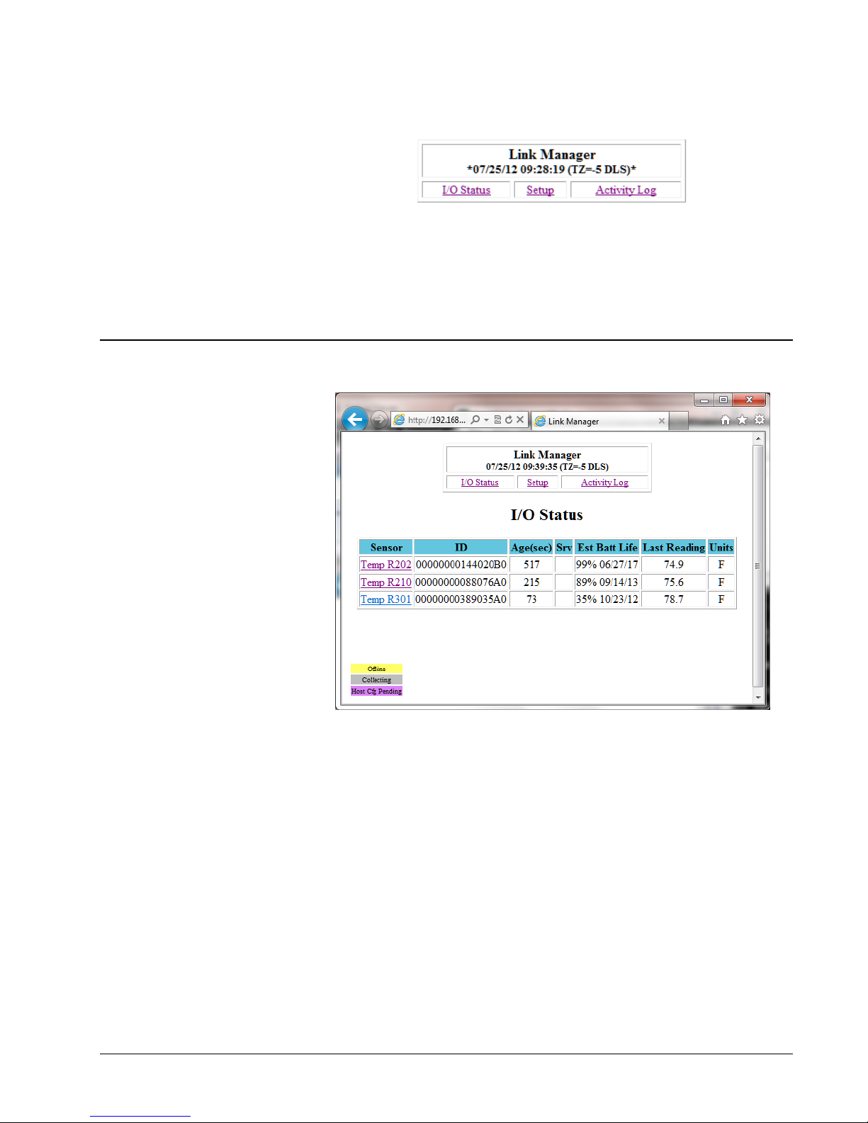
I/O Status
The Link Manager will frame the time and date and timezone with “*” to indicate
that the Automatic Time Update could not update the real time clock. Just because
the automatic time update failed does not necessarily mean the clock is wrong but
that the clock has not been synchronized.
The Link Manager shows the current state of the sensor in the I/O Status page. The
following information is presented:
Name – Name of the sensor. Click on the name to show the “Sensor Setup”
page. The name is only used within the Link Manager and is not given
to the host application.
ID – Serial number of the sensor. The serial number is used to identify the
sensor to the host application.
Age – Number of seconds since the last communications with the sensor.
Est Batt Life – Estimated battery life remaining shown as the percentage of
the battery remaining and also the estimated date at which the battery
will be exhausted.
Link Manager Manual User Interface 19
Last Reading – the last I/O reading from the sensor.
Units – Engineering units of the Last Reading.
Page 22

Sensor Setup
The Link Manager will highlight the row color of a sensor to indicate a sensor
condition:
Offline – yellow – sensor is determined to be offline (as set in the Manager
Setup page)
Collecting – gray – the Link Manager is currently collecting or is expecting
to collect logged data from the sensor.
Host Cfg Pending – amber – the Link Manager has received a sensor
configuration change from the host application is waiting to send that it
on the next contact from the sensor.
The I/O Status page is refreshed every 15 seconds. Hit the Refresh button on your
browser to refresh the page on demand.
Setup Menu
From the Sensor Setup page, you can change the name of the sensor or delete the
sensor from the Link Manager. The name field is used only by the Link Manager
and not sent to the host application.
20 User Interface Link Manager Manual
The Setup Page gives a list of the setup options.
Page 23
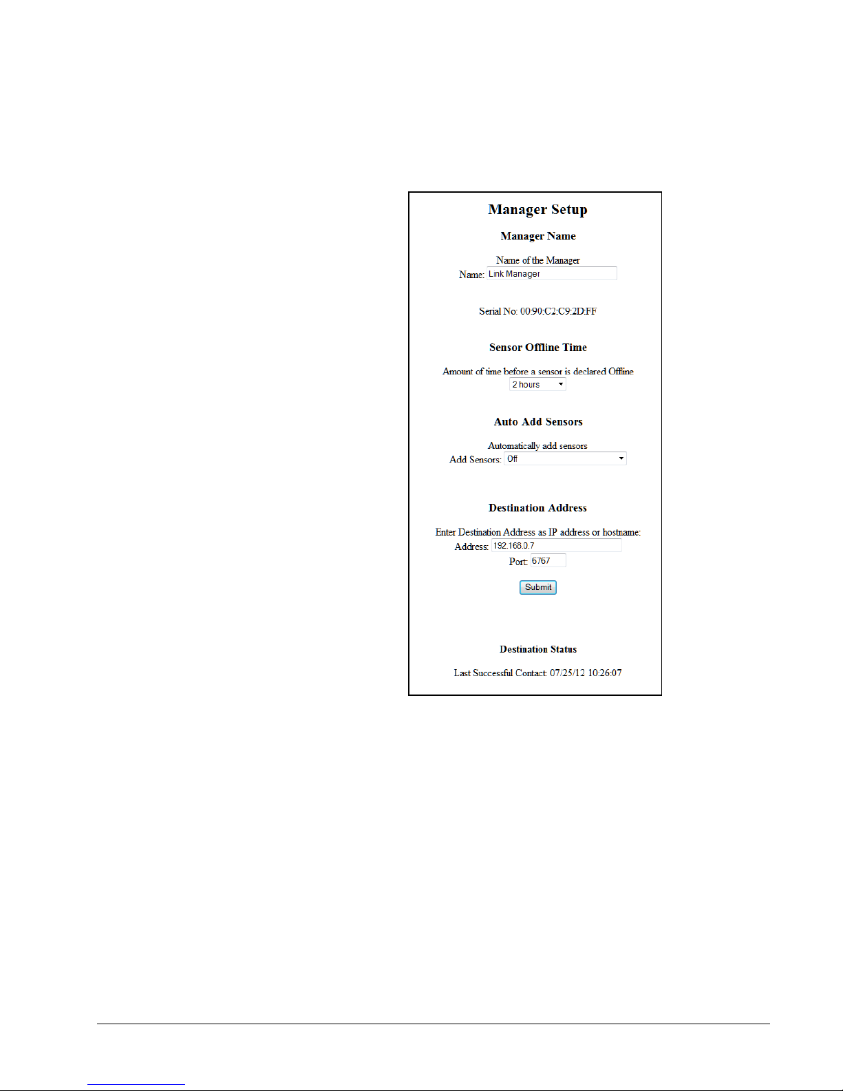
Manager Setup
The Manager Setup page allows you to configure the following:
Name – name of the Link Manager (shown in the main menu).
Serial No: MAC address of the Link Manager
Sensor Offline Time: the amount of time given before the Link Manager
identifies the sensor as being offline. Used by the Link Manager only;
not provided to the host application.
Auto Add Sensor: The amount of time the Link Manger gives to allow
sensors to be added via radio using the sensor’s service button.
Destination Address: The IP address or hostname of the host application
where the Link Manager will send the sensor data.
Link Manager Manual User Interface 21
Destination Port: The port number that the host application is listening for
data that the Link Manager will send. Default is 6767.
Page 24
In the Destination Status, the Link Manager indicates the condition of the last
attempt to make contact with the host application. The Link Manager shows the time
and date of the last successful contact. If the last contact attempted failed, the Link
Manager will show an error message.
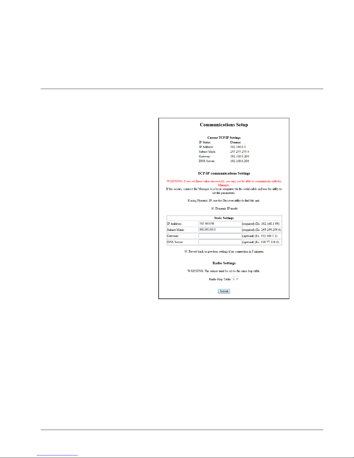
Communications Setup
The communication page shows that current settings of the Link Manager and allows
the user to change the communication parameters:
Current TCP/IP Settings – The Link Manager shows the current IP address,
Subnet mask, Gateway address and the DNS Server. These parameters
may be set statically or dynamically.
Dynamic IP mode – when checked the Link Manager will have the IP
parameters assigned dynamically from a DHCP Server; unchecked, the
Link Manager will the IP parameters entered and set statically.
Revert back to previous settings if no connection in 5 minutes – if checked
the Link Manager will revert back to previous settings if no contact is
made with the Link Manager in 5 minutes. If you cannot make contact
with the Link Manager after making changes, wait 5 minutes and the
Link Manager will revert back to the previous settings.
22 User Interface Link Manager Manual
Page 25
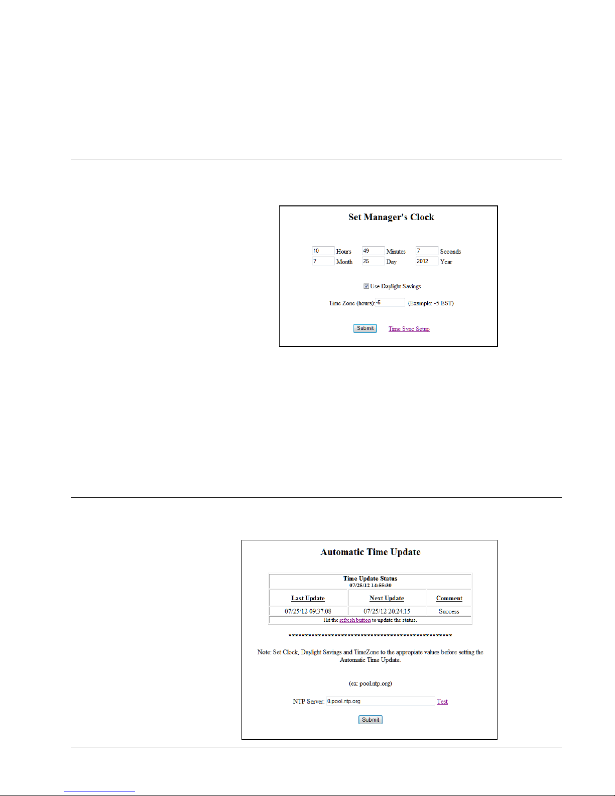
Set Manager’s Clock
Radio Hop Table: default is 3. Select the desired radio channel hop table.
The sensor’s radio must be set to this same value using the Point
Sensor Utility.
Set the Link Manager’s time of day clock, daylight savings mode and time zone.
Time: Hours, Minutes, Seconds: set the current time of day.
Date: Month, Day, Year: set the current date.
Use Daylight Savings: check if using Daylight Saving mode.
Time Zone: set the time zone offset in hours.
Time Sync Setup: click link to show the “Automatic Time Update” page.
Automatic Time Update
Link Manager Manual User Interface 23
Page 26
The Link Manager can update its clock from an external time server. The top
portion of the page shows the current status of the last update with the time server:
Last Update: timestamp of the last update with the time server.
Next Update: timestamp of the next scheduled update with the time server.
Comment: current status with the last update of the time server. The Link Manger
will show an error message if the last update failed or “Success” if the manager
successfully updated its time.
The NTP Server field specifies the address of the time server (hostname or IP
address). To stop the Link Manager from obtaining time from a time server, just
blank the NTP Server field.
The “Test” link starts the update process now instead of waiting for the next
scheduled update.
Click the browsers refresh button to update the Time Update Status section.
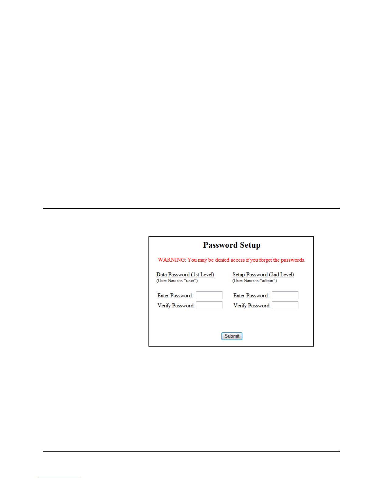
Passwords Setup
Link Manager can control access to the different resources of the Link Manager
through passwords. There are two levels of login access for the Link Manager: Data
and Setup. Through the Data Login, the Link Manager allows access to the data
portions of the Link Manager like the I/O Status page. Through the Setup Login, the
user can make changes to the Link Manager setup. With the Setup Login, the user
has all the rights of the Data Login as well.
24 User Interface Link Manager Manual
If you set up a password to restrict viewing ("Data Password") you must also
configure a Setup Password. If you configure a password for Setup ("Setup
Password") without setting the “Data Password” then viewing of data is not
Page 27
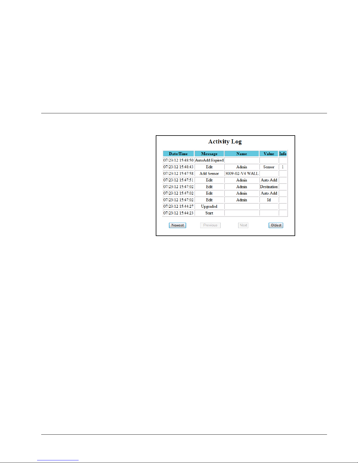
Activity Log
restricted. In other words, you can have password restrictions for 1) Data and Setup,
2) Setup only, or 3) Neither. You cannot restrict passwords for Data only.
Click "Submit" to establish password protection in the Link Manager.
WARNING: User Name and Password are case sensitive.
Note: for the Data resources use the username “user”; for Setup resources use the
username “admin”.
The Link Manager stores changes in setup and changes in sensor state in an activity
log. The activity entries can be viewed to troubleshoot issues or know when a
condition for the sensor has changed. The Link Manager shows the latest events first
and in descending order. The Link Manager shows 10 events at a time. You can
move through the Activity Log by using the following links that are at the bottom of
the page:
Newest – the Link Manager shows the latest events. This the default page
when first select Events from the menu.
Previous – the Link Manager shows the previous (older) events.
Next – the Link Manager shows the next (newer) events.
Oldest – the Link Manager shows the first events that were logged.
The Activity Log page fields are the following:
Date/Time: date and time when the event occurred.
Message: event description
Name: Name of the sensor or the action.
Link Manager Manual 25
Value: The target of the activity.
Info: additional information about the event. For sensor this will be the row
number in the sensor table for the sensor.
Page 28

Usage Notes
Notes
1. When a sensor is registered for the first time, the Link Manager only starts
contacting the host only when the configuration data and the whole logged data
is collected.
2. The Link Manager starts initiating a connection to the host only after the sensor
makes contact with the Link Manager. The Link Manager initiates contact after
all the data has been collected. The sensor’s Transmit Period dictates how often
the Link Manager attempts to make contact for that sensor.
3. If the Link Manager cannot contact the host, the Link Manager will retry every 5
seconds.
4. If the sensor’s log buffer is full, it takes 2 minutes for the Link Manager to
collect all of the sensor’s configuration and logged data.
5. The Link Manager has a conversation with one sensor at a time.
6. The Link Manager will transfer a sensor’s data to the host one at a time.
7. Using more than one Link Manager within radio range:
a. A sensor must be registered to just one Link Manager. If the same
sensor is registered to multiple Link Managers, this will cause
confusion to the whole system.
b. Have only one Link Manager in AutoAdd mode at a time.
c. If using 20 or more sensors in the system, consider assigning a unique
radio Hop Table for the Link Manager and the sensors to isolate Link
Managers and sensors. The isolation will help reduce interference from
sensors which will improve performance (reduced collection times and
retries).
8. Make sure Link Manager’s 900 Mhz antenna is secured tightly.
9. Sensor configuration information can be sent to the sensor via the Link
Manager. When the host sends the sensor configuration when the Link Manger
contacts the host application with sensor data, the Link Manager will highlight
the sensor row in the I/O Status with the color maroon. On the following
contact with the sensor, the Link Manager will send the configuration
information to the sensor at which point the Link Manager will show the normal
background color for the sensor row. It takes two conversations with the sensor
for the configuration information to be transferred.
26 Usage Notes Link Manager Manual
Page 29

10. When the sensor configuration is changed locally at the sensor (using the Point
Sensor Utility), the Link Manager will read the sensor configuration from the
sensor on the following contact and make the information available to the host
application.
Link Manager Manual Usage Notes 27
Page 30

Development Notes
Overview
The Link Manager follows the “Extended Point Sensor Packet Specification”. If you
have written an interface for Wifi Point Sensor, then the Link Manager will work
with your interface. There are two features that you will want your interface to take
advantage of the details that differs from using the Wifi Point Sensor:
1. When the Link Manager recollects the whole sensor buffer, it will set the
“Link Manager recollected sensor’s buffer” bit in the “status2” byte in the
beacon packet. The Link Manager collects the whole sensor buffer under
the following conditions:
a. First time collecting the sensor data.
b. If the current sensor clock is less than the previous sensor clock
value. This can happen when the sensor’s log buffer is cleared.
2. The “org” – origin value in the beacon packet is set to 7 to indicate the data
3. The Mac field in the beacon packet is set to the Link Manager’s MAC
“I Am Here Packet”
Link Managers will transmit an “I am here” UDP packet to the host when the Link
Manager has not sent a UDP packet on behalf of a sensor for more than 5 minutes. If
no sensors are registered, the Link Manager will send the “I am here” packet every
30 minutes. The Link Manager sends the Cmd 5 which is the same command as the
Point Sensor Utility sends for the Contact Destination packet. The Link Manager
sets the MAC field to its MAC address and sets the “org” field to 7. All other fields
are set to 0.
c. If the sensor has been offline for the time it takes to fill the log
buffer to 3/4s full (logging at 2 mins, this is 3 days).
came from a Link Manager
address.
28 Development Notes Link Manager Manual
Page 31

Link Manager sends:
C3 3C 00 05 00 00 30 30 3A 39 30 3A 43 32 3A 43 35 3A 31 41 3A 34 30 00
00 00 00 00 00 00 00 00 00 00 00 00 00 00 00 00 00 00 00 00 00 00 00 00
00 00 00 00 00 00 00 00 00 00 00 00 00 00 0D 07 00 00 00 00 00 00 00 00
00 00 00
Host responds with:
C3 3C 00 06
Link Manager Manual Development Notes 29
Page 32

Common Software Tools
Software
Discover Utility
Discover utility identifies Link Managers on a network. It lists Link Managers found
using the UDP Discovery feature. The Discover provides key properties of the Link
Manager: name, type, IP address, firmware version and other communication
parameters. The Discovery provides a convenient launch pad to launch the web
browser pointing to the Link Manager’s I/O status web page and launch
HyperTerminal or Telnet to connect to the selected Link Manager. Contact your
dealer to obtain this utility.
PC Utilities and Tools
The interface to the Link Manager was designed to meet common standards and be
easy to use. You can use common software that either comes with your PC
operating system or can be purchased to diagnose common problems and to
communicate with the Link Manager. You can use a communication program that
has terminal emulation to get familiar with the Link Managercommands and
communications. Once you are familiar with the commands, you can automate the
communications using common development programming languages.
Here are some examples of common software:
Ping – simple program to test the TCP/IP connection.
Telnet – simple program to send commands and see responses via TCP/IP.
Note: Link Manager uses port 1000 as default.
Ipconfig – utility that shows the computer’s IP address (command line
utility).
HyperTerminal – (Windows Only) provides terminal emulation program to
communicate via TCP/IP and serial port.
Procomm (Symantec) – (Windows Only) third party program – provides
terminal emulation to communicate via TCP/IP and serial port.
30 Common Software Tools Link Manager Manual
Page 33

Link Manager Advanced
Functions
Current I/O Readings
The current readings of the sensors can be obtained by issuing a “D” command. The
Link Manager will return the row number in the sensor table, the current readings of
the sensors and flags indicating “state of concern”. The current reading can be
obtained at any time when there is a connection established. Use the “S” command
to determine the number of sensors in the sensor table.
Example
Command: <^B>S<CR>
Response: <^B>S,2,na,na<CR>
Command: <^B>D1-2<CR>
Response: <^B>D1-2,F0600002FFFtrans.|F8|F2,0200021FTF69|F77.0<CR>
Command: <^B>D1-2<CR>
Response: <^B>D1-2,F0600008FFFtrans.|F8|F2,0200027FTF69|F77.0<CR>
Remarks: “F” no system alarm; First sensor: “06” – LSX, “00008” – age,
“FF” – no sensor state of concern, no service button, “Ftrans.|F8|F2” –
data with no I/O Point state of concern; Second sensor: “02” –
Humidity/Temperature, “00027” – age, “FT” – no sensor state of concern
but service button was pressed, “F69|F77.0” – data with no states of
concern.
Pass-Thru Mode
Link Manager Manual Link Manager Advanced Functions 31
Overview
Link Manager can be placed in a mode where packet information that it receives can
be repeated via Serial, Ethernet, Command Radio, RS-485 or UDP. Link Manager
can forward these packets as is or convert the data to engineering units and send it as
a comma delimited record. Any packet received either through receiver or any of the
media will be repeated through the media that are in Pass-Thru mode. A packet
received through a media will not be repeated through that specific media. For
instance if a packet was received through the Command Radio, the Link Manager
will not repeat the packet through the Command Radio even though it is in PassThru mode.
Page 34

The Link Manager provides three modes for Pass-Thru: Standard, Extended and
Engineering. For Standard mode the Link Manager passes through the sensor packet
as is. It also pulls the embedded standard packet out of the extended packet. For
Extended mode, the Link Manager passes through extended packets as is and also
standard packets. For Engineering mode the Link Manager parses the sensor packet
contents and sends the data as a comma delimited record. In Engineering mode, the
sensor must be listed in the Sensor table before the Link Manager can send the
record.
All Media
To set up the Link Manager for Pass-Thru mode, send the “US” or “UX” command
on the media you wish to receive packets. The standard packet is an ASCII
Hexadecimal string of 29 characters (or 31 characters if location information from a
Point Repeater is included). The extended packet is a 75 binary packet with an
embedded standard packet. The type of packet and content depends on the type of
transmitter that originally sent the packet. Check the specification for the transmitter
for more information.
Use the "UM" command to place other media (other than the one currently
connected) in or out of Pass-Thru mode. Use the "UMR" command to determine
which media are in Pass-Thru mode.
The Link Manager can also convert the Pass-Thru data to engineering units. Link
Manager will only forward packets from sensors that are contained in the Sensor
Table. The Sensor Table must be previously set up either by adding sensors using
the “CSC” command or Auto Add Mode. The record for Engineering mode is
formatted as follows:
Location,name,type,serial no,warn,service(,warn1,value1,unit1)..(,warnn,valuen,unitn)
Where:
location – Point Repeater Location ID (‘a’ to ‘z’). If not Point Repeater
Location ID is available, Link Manager will return ‘na’.
name – name of the sensor
Type – type of sensor (enumerated) See the “CS” command for more
information
serial no – sensor serial number
warn – is the sensor in a “state of concern” (T or F)
service – packet produced from the Service button on the transmitter being
pressed.
32 Link Manager Advanced Functions Link Manager Manual
Page 35

warnn – is the I/O point in a “state of concern” (T/F)
valuen – value of the I/O point
unitn – engineering units label of the I/O point
Example
na,2Humid_Temp,2,D40000000B1FBD28,F,F,F,45,%RH,T,71.6,F
Remarks:
warn, value and unit are repeated for every I/O point of the sensor. For the actual
data fields, consult the specification for the transmitter being used.
To place the Link Manager in Pass-Thru mode with engineering unit conversion,
send the “UE” command on the media you wished to receive packets.
For the media in Pass-Thru mode, the Link Manager does not apply the Inactivity
Timeout.
Link Manager can passively wait to be placed in Pass-Thru mode or actively push a
connection and then go into Pass-Thru mode. Link Manager has a Pass-Thru Media
Callout Table that it uses to place and maintain a connection with the Link Manager
in Pass-Thru mode. The “CUS”, “CUX”, “CUE”, “CUR” and “CUC” commands
are used to set and maintain the Pass-Thru Media Callout Table. You specify the
media to push, the type of Pass-Thru mode and how aggressively to retry the
connection if the connection is disrupted.
UDP Pass-Thru
Using UDP Pass-Thru
Link Manager Manual Link Manager Advanced Functions 33
UDP Pass-Thru to Host
Page 36

UDP Pass-Thru to Master Link Manager Connected to Host
By using the UDP Pass-Thru feature, Link Managers can be used in a variety of
topographies. The Link Manager can be used as essentially as an Ethernet repeater
supplementing the RF repeater network therefore the Ethernet networking
infrastructure at a facility can be leveraged. The network of Link Managers can be
configured to repeat sensor packets to a central Link Manager that may then be
configured to connect to the Internet. Instead of a central Link Manager, a PC can be
used. Link Manager can pass through sensor packets to one or more destinations.
Link Managers support 3 different modes to balance ease of setup and use of
network resources.
UDP Pass-Thru Modes
Broadcast mode: When the Link Manager receives a sensor packet through any of
the media, the Link Manager will repeat this packet by broadcasting the packet to the
network using UDP. All network devices within this network segment listening on
port will hear this packet. Some routers may not support UDP broadcast.
Discovery mode: If the Link Manager receives a discovery UDP packet, the Link
Manager will take the source IP and add it to the Pass-Thru Destination table. The
Link Manager will start repeating sensor packets to the source IP address. If the
Link Manager does not receive the discovery UDP packet within 15 minutes, the
Link Manager will remove the source IP address form the Pass-Thru Destination
table. The Link Manager will then stop repeating packets to that destination. The
discovery UDP packet will need to be sent periodically in order for the Link
34 Link Manager Advanced Functions Link Manager Manual
Page 37

Repeater Mode
Manager to continue to repeat sensor packets to the destination. Up to 5 destinations
can be supported.
Set destination mode: If the Link Manager receives a Set Destination UDP packet,
the Link Manager will add the destination IP address that is embedded as parameter
in the packet to the Pass-Thru Destination table. The Link Manager will start
repeating sensor packets to the source IP address. If the Link Manager does not
receive the discovery UDP packet within 15 minutes, the Link Manager will remove
the source IP address from the Pass-Thru Destination table. The Link Manager will
then stop repeating packets to that destination. The Set Destination UDP packet will
need to be sent periodically in order for the Link Manager to continue to repeat
sensor packets to the destination. Up to 5 destinations can be supported.
If the Link Manager has not received a sensor packet within 30 seconds, the Link
Manager sends the UDP Pass-Thru packet with sensor packet field set to NULL (0s).
The host application can then determine that the Link Manger is still alive but not
receiving packets.
Link Manager can be placed in a mode where it will resend a received standpacket
out the same communication media that it was received (Serial, Ethernet, Radio or
RS-485). The Link Manager first passes the packet through a filter to determine if
to resend the packet. If the Link Manager receives the same packet within 4 seconds
of the original, it will not resend the packet; after 4 seconds it will send the packet.
This filter prevents the Link Manager from getting locked up in an infinite loop of
sending the same packet again between other repeaters. A typical application for
using the Repeater Mode is to extend a 900 Mhz/2.4 Ghz network. The Link
Manager can also add a locator identifier (an alpha character) to the sensor packet.
This locator identifier can be used to identify where the sensor packets was placed
onto the network.
The “CXC”, “CXR”, and “CXS” commands are used to clear, read and set the
Repeater Mode. Use the “CYPS” command to set the locator identifier. With the
“CXSm,SF” command the Link Manager will only repeat standard packet or the
embedded standard packet part of an extended packet. With the “CXSm,XF”
command the Link Manager either standard packets or extended packets.
To setup the Link Manager to “repeat” the 418/433 Mhz packets as well as the 900
Mhz/2.4 Ghz packets, set the Radio media in PassThru mode using the “UMSRS”
command and then put the Radio media in Repeater Mode using the “CXSR,ST”
command.
Link Manager Manual Link Manager Advanced Functions 35
Page 38

Support Functions
Discovery
Using the Discovery feature, Link Managers on a network can be identified by name.
The following information is obtained: identifying name, local IP address, port
number, number of sensors, HTTP port, UDP port, MAC address, Locator ID and
firmware version. The discovery feature is especially useful when the IP address of
the Link Manager is set dynamically; there is no convenient way to find the Link
Manager otherwise. The Discovery feature is enabled by default. Use the “CYP”
command to enable/disable this feature.
When an UDP Discovery Request is received, the Link Manager will respond with a
UDP Discovery Response which contains the describing information. An
application can send the UDP Discovery Request to a specific Link Manager or
typically the application will broadcast the packet across a LAN segment or network
where a router will support broadcast packets. The UDP Discovery Response is
directed to the sender.
The Discover Utility is a PC Windows application that is provided with the Link
Manager. Contact your dealer to obtain a copy of the utility. The Discover Utility
will list the found Link Managers. It provides a convenient launching point to start
the browser and view the Link Manager web pages or start other communication
utilities.
In the Appendix, the sections Packet Formats: UDP Discovery Request and UDP
Discovery Response discuss the format of the UDP packet to be able to customize an
application to support the Discovery feature.
DHCP
The Link Manager can have its IP address automatically assigned by a DHCP server.
The Link Manager can have its IP address, subnet mask, gateway, name server and
SMTP server dynamically assigned. By default, the Link Manager is set up for
dynamic IP. To enable or disable dynamic addressing, use the “CID” command. If
the Link Manager cannot find a DHCP server, the Link Manager will fall back to the
static IP address or use the IP address of “0.0.0.0” (depending on the setting of the
“CID” command). At power up, if the Link Manager had an IP address previously
assigned, the Link Manager will fall back to this address if the DHCP server cannot
be found. The Link Manager will periodically try to make contact with the DHCP
server until the DHCP server provides the IP address. Use the “IP” command to
retrieve the current IP address (whether dynamically assigned or statically assigned).
Note: To determine the dynamically assigned IP address, issue the "IP" command
across any of the media or use the Discover utility.
Factory Reset
To reset the Link Manager back to factory settings, do the following procedure:
1. Power down the Link Manager.
2. Press and hold the reset button on the rear communication panel of the Link
Manager.
36 Link Manager Advanced Functions Link Manager Manual
Page 39

3. While pressing the reset button, power up the Link Manager. The Link
Manager will blink the power LED once a second.
4. Release the reset button.
Link Manager Manual Link Manager Advanced Functions 37
Page 40

Communicating with the Link
Manager
Link Manager Protocol
The system for communicating with the Link Manager is based on a commandresponse architecture. Every submitted command will receive a response, as long as
there is a connection. Successful commands are responded to with an echo of the
primary command, and if the command returns data, the data is appended to the
primary command echo after a comma (if the comma is part of the command). The
primary command is the submitted command string in its entirely or up to but not
including the first comma. Sending the next command before receiving a response
to the last command is an error.
Each command must be prefixed with an ASCII 02 character (STX) (on most
terminal emulation programs, type Ctrl-B) and must end with an ASCII 13 character
(CR) (on most terminal emulation programs, type Ctrl-M or Enter). This protocol
will work with all the Link Manager communication media: Serial port, Command
Radio (option) and TCP/IP.
Example
Command: <STX>S<CR>
Response: <STX>S,6,082701111800,na,na<CR>
Remarks: <STX> is an ASCII 02 (or Ctrl-B on the keyboard)
<CR> is an ASCII 13 (or Ctrl-M or Enter on the
keyboard)
There is an additional layer of communications protocol that is media-specific. This
has been added to ensure reliability when using media lacking built-in error
detection. This protocol is recommended to be used with the Link Manager’s
Command Radio, and Serial ports. The command must be prefixed with an ASCII 01
character (SOT) (on most terminal emulation programs, key in Ctrl-A), then
following the command with a 4-character ASCII hex CRC16. The command is
then terminated with an ASCII 13 character (CR) (on most terminal emulation
programs, key in Ctrl-M or Enter). The CRC16 must be calculated using the full
command but does not include the ASCII 01 (SOT) or the ASCII 13 (CR). An
38 Communicating with the Link Manager Link Manager Manual
Page 41

ASCII 01 (SOT) prefixed command not followed by a CRC16 will result in an error.
Link Manager will respond with a response prefixed with an ASCII (SOT), followed
by a 4-character ASCII hexadecimal CRC16 and terminated with the ASCII 13 (CR).
The returned CRC16 is calculated using the full response but does not include the
ASCII 01 (SOT) or the ASCII 13 (CR).
Note: The letters of the 4-character ASCII hexadecimal CRC16 must be in
uppercase.
Example
Command: <SOT>S3D40<CR>
Response: <SOT>S,6,082701111800,na,na3A3E<CR>
Remarks: <SOT> is an ASCII 01 (or Ctrl-A on the keyboard);
<CR> is an ASCII 13 (or Ctrl-M or Enter on the keyboard); “3D40” is
the calculated CRC16 value in 4-character ASCII hexadecimal of the
command “S”; “3A3E” is the calculated CRC16 value in 4-character
ASCII hexadecimal of the response “S,6,082701111800,na,na”.
Note: Command Radio requires the <SOT>cmdCRC16<CR> protocol. Command
sent using the <STX>cmd<CR> protocol will not be honored. If the "CTB"
(<SOT>CTB254F<CR>) command is sent, the Link Manager will process the
<STX>cmd<CR> protocol will be honored until the connection closes (usually
because of the inactivity time). Issue the “CTF” command to always use the
<SOT>cmdCRC16<CR> protocol. The “CTP” command may be used to achieve the
same results as the “CTB” and “CTF” commands, but has the ability to configure the
protocol for a specific media.
CRC16 Algorithm
The CRC16 Algorithm is a sophisticated method of checking the integrity of
transmitted data for transmission errors. The algorithm indicates whether or not the
data has any error. It does not indicate which bit or how the error occurred. Link
Manager ignores data packets that have errors. The host should resend the command
if the response from the Link Manager has errors.
Link Manager Manual Communicating with the Link Manager 39
Page 42

Example C function
// on entry: dataptr – pointer to array of bytes – pointer to start
of the bytes to be CRC16.
// len – number of bytes in the array to apply CRC16
// seed – starting seed of the CRC16 (for Link Manager use 0)
// on exit: calculated CRC16 value
const short oddparity[16] = { 0, 1, 1, 0, 1, 0, 0, 1, 1, 0, 0, 1, 0, 1,
1, 0 };
Word DoCRC16(byte *dataptr, Word len, Word seed)
{
Word CRC16;
int i;
Word data;
CRC16 = seed;
for (i=0; i<len; i++)
{
data = dataptr[i];
data = (data ^ (CRC16 & 0xff)) & 0xff;
CRC16 >>= 8;
if (oddparity[data & 0xf] ^ oddparity[data >> 4])
CRC16 ^= 0xC001;
data <<= 6;
CRC16 ^= data;
data <<= 1;
CRC16 ^= data;
}
return CRC16;
}
40 Communicating with the Link Manager Link Manager Manual
Page 43

General information
I/O Point Type
Configurable Parameters
Analog
Scale
Offset
Units
Decimal Places
Integer
Scale
Offset
Units
Decimal Places
Data
Presented as ASCII hexadecimal
State
Name
1
, …, Name
x
Sensors
All sensors have two unique identifiers:
The Link Manager keeps a list of sensors and all configured I/O points in a table.
The user can use a command string to associate a sensor’s serial number with a label,
and configuration information for all of the sensor’s I/O points. The row number in
the sensor table is used to specify the sensor
I/O Points
In addition to the two identifiers, sensors also contain a varying number and type of
I/O points. I/O points collect or contain measurable values such as temperature,
identification, count, etc. Each I/O point contains configurable parameters. You can
read and change these parameters using the “C” command, which will be explained
in more detail below.
Sensor Table: The sensor table can hold up to 100 sensors, having among them a
maximum of 200 I/O points.
Serial Number – Internal, factory assigned, unique, can’t be changed.
Name – a label that the user assigns.
I/O Point Type
Link Manager Manual Communicating with the Link Manager 41
Analog
Analog I/O points are configured using a scale and offset to convert the data into
engineering units. A scale is a multiplier for the data. Before data from a configured
I/O point is displayed, it will be multiplied by the scale. The offset is then added. In
this way the user can control the units in which data from an I/O point is displayed.
All temperature I/O points are treated as signed 16 bit values where 1 bit is 1/16th of
a degree Celsius. All Analog I/O are treated as signed 16 bit values. If the Analog
I/O from the sensor is 12 bits, the data value is normalized to 16 bits in the Link
Manager (multiply by 16). The value of an Analog I/O point will be displayed as
(raw data * scale) + offset. The following table contains common scales and
offsets:
Page 44

Scale
Offset
Units
0.0625
0
Degrees Celsius
(1/16 of a degree)
0.1125
32
Degrees Fahrenheit
(1.8 * 0.0625)
0.00305
0
% of full scale
0.125
0
Raw 12 bits
1.0 0 Raw signed 16 bits
Common Analog Scales and Offsets
Integer
Integer I/O points work similarly as Analog I/O points. A scale and offset is applied
before the data is displayed or delivered. However for Integer I/O points the offset is
applied before the scale and is an integer value (can be used to zero the reading).
The value of an Integer I/O point will be displayed as (raw data - offset) * scale.
For example, suppose you have a wireless rain gauge and 1 count of the rain gauge
equals 0.1 inches. And suppose you want to show in the I/O Status page the amount
of rain since the beginning of the year. You set up the scale to be 0.1 and the offset
to be the count of the sensor at the beginning of the year and suppose the
accumulated count is 233489 at the beginning of the year. So in this example the
scale is 0.1 and the offset is 233489.
State
State I/O are discrete I/O points. The number of states for the State I/O depends on
the type of Sensor (for instance a Counter has four states and a Discrete has two).
The meaning of the states depends on the type of sensor. Each state can be named.
Data
A Data I/O contains 8 bytes of data. How these 8 bytes are used depends on the type
of sensor. Link Manager can present this data in one of three ways: as character
data, Serial Number as ASCII Hexadecimal or ASCII Hexadecimal.
42 Communicating with the Link Manager Link Manager Manual
Page 45

Command Overview
Syntax Element
Purpose
< >
Enclose a set of options, ones of which is required
|
Separates elements in a set of options
[ ]
Enclose an optional expression
…
Denotes variable length
1
,…x
Marks repeatable expression
n
Only or low row number of a sensor
m
High row number of a sensor
Italics
Strings in italics are place holders for values
Command Syntax
The following table describes the shorthand used to define each command.
Rules governing commands include:
Command strings may contain no spaces.
Reserved characters: commas (,), pipes ( | ), SOT (ASCII 1), STX
(ASCII 2), colons (:), carriage returns (ASCII 10), and the bell code
(ASCII 7) are reserved, and may only appear as part of the command
syntax. Do not use these characters in label names or state names.
Command strings have a maximum length of 128 characters.
When specifying a range, the maximum is ten sensors. Specifying a
range including more than ten will return an error.
Time representations
Date and Time Stamps
Time and date stamps or times that are set or compared to the real-time clock are
always expressed in military time and represented as:
mmddyyhhnnss
Where
mm – month of the year
dd – day of the month
yy – year starting at year 2000
hh – hours
nn - minutes
ss - seconds
Link Manager Manual Communicating with the Link Manager 43
Page 46

Interval or Duration Times
Times that are duration are always expressed in military time and represented as:
hhnnss
ddhhnnss
Where
dd – number of days
hh – number of hours
nn – number of minutes
ss – number of seconds
Future Compatibility
All commands and fields will be maintained for downward compatibility. Future
function in the Link Manager will be added by extending commands with commas
and adding new commands. These added fields will be optional for the command
syntax.
44 Communicating with the Link Manager Link Manager Manual
Page 47

Command Outline
Command
Description
Options & Parameters
AT[U]|F|R|S[U] >
Auto Add Mode
<True[Unfiltered]|False|Read|Service[Un
filtered]>([,auto off])
C<B|E>
Configure Notify
<Begin|End>
CC<S[F|S]|R>
Configure/Read
Clock
<Set[Force| Synchronize]
|Read>(mmddyyhhnnss)
CCN<S|R>
Configure
Automatic Time
Update
<Set|Read>(host name)
CD<S|R>
Configure/Read
Link Manager
Identification Label
<Set|Read>(ID Name)
CI<S|R>
Configure/Read
Link Manager IP
Address
<Set|Read> (IP Address, Subnet [,
Gateway][, Name Server][,Port])
CID<S|R|C>
DHCP Enable
<Set|Read|Clear>(dynamic,fallback)
CIP<S|R>
IP Ports
<Set|Read>(httpport, cmdport)
CP<D|C>
Configure Login
Passwords
<Data|Configure> (password)
CR<S|R>
Configure Radio
<Set|Read>(hop table, network id)
CS<S|R|C[F]|D[F]>[n]
Configure/Read/Cle
ar /Delete Sensor
Setup
<Set|Read|Clear[Force]|Delete[Force]>
(sensor index, serialno, label(I/O point
setup(s)))
Analog:
(AScale,Offset,Units,Decimal_Places)
Integer:
(IScale,Offset,Units,Decimal_Places)
Data: (D<Y|N>)
State: (SName1[,…Namex]), sensor
type
CT<S|R>
Configure Media
Ports
<Set|Read>(mediainstanceMedia)
CTB
Set Simple Protocol
CTC<S|R>
Enable Command
Processor
<Set|Read>(InstanceMediaCmdproc)
CTF
Set CRC16 Protocol
CTP<S|R>
Set CRC16 Protocol
Direct
<Set|Read>(InstanceMediaCRC16)
Command List
Link Manager Manual Communicating with the Link Manager 45
Page 48

CV<S|R|C>
Configure
Enumerated
Engineering Unit
Conversion
<Set|Read|Clear>
CX<C|R|S>
Configure Media
Repeater Mode
<Clear|Set|Read>(Media,RepeaterAck)
CYD<D|R|S>
Configure UDP
Pass-Thru
Destinations
<Set|Read|Delete>(row)
CYP<R|S>
Configure UDP
Pass-Thru
Parameters and
Discovery
<Set|Read> (mode, discovery,
passthrulisten, tries, locator, ptmode,
port)
D<n|n-m>
Get Last Data
EC[A]
Clear Activity Log
[All](mmddyyhhnnss)
E<A|F|L|N|P|R[V]
Read a Activity Log
Record
<Again|First|Last|Next|Previous|Read
using time> [Verbose]
(mmddyyhhnnss)<index>
EU
Activity Log Usage
IC
Information Counts
IIU
Information UDP
Pass-Thru
Destination
ILR
Information Sensor
Log Delivery
ILT
Information Sensor
Log Delivery Table
IM
Media Information
IP
Information IP
Settings
(isdynamic,successfully bound,IP
address, subnet mask, gateway, name
server, SMTP server)
IPS
Information DHCP
(DHCP Acquire state, DHCP state,
lease time, wait time, link)
IT<S|R>
Time Zone
Information
<Set|Read> (time zone
hhmmss,daylight savings)
ITD<D|R|S>
Daylight Savings
Schedule
<Daylightschedule|Read|Set>
IU
Information PassThru
(media state, last action, next action)
IV
Version Information
IY
Clock Synchronize
Information
L<I|O|OC>
Login/Logout
<In|Out|Out&Disconnect> (password)
PY
Attempt Automatic
Time Update
S
Get Status Data
U[E|N|Q|R|S]
Pass-Thru Mode
[Engineering Mode|No|Quiet
Mode||Read|Standard Mode]
UM[S|R]
Pass-Thru Mode
Direct
<Set|Read>(InstanceMediaMode)
V<B|E>
Verbose Mode
<Begin|End>
46 Communicating with the Link Manager Link Manager Manual
Page 49

Commands
Command Options
A<T[U]|F|S[U]|R>
Command/Response Syntax
Command: AT[,auto off] turn AutoAdd Mode on
Response: AT
Command: ATU[,auto off] turn AutoAdd Mode on
Response: ATU
Command AF turn AutoAdd Mode off
Response: AF
Command: AS[,auto off] turn on AutoAdd (add when service
pressed)
Response: AS
Command: ASU[,auto off] turn on AutoAdd (add when service
pressed)
Response: ASU
Command: AR,remaining time Query AutoAdd Mode
Response: AR,<T|S|F>
Parameters
Where: ‘T’ – true or yes
‘F’ – false, no or off
‘S’ – service mode
‘R’ - read
auto off – (ddhhnnss) specify the amount of time before auto add mode is
turned off. This time is running time (while the Link Manager is powered
down this time does not elapse). (optional)
remaining time - (ddhhnnss) the amount of time remaining before the auto
add mode is turned off.
Login Level
Login Level: AR – Data
AT,AF,AS, - Configure
A’ - Auto Add Mode command
Link Manager Manual Commands 47
Page 50

Description
If AutoAdd mode is enabled and the Link Manager receives a packet from a sensor
not already in the sensor table, it will add the new sensor to the table automatically.
When the Link Manager adds a sensor to the sensor table through AutoAdd mode it
assumes certain defaults for the parameters based on the type of sensor. You can
then modify these parameters using the “CS” command. The Link Manager will add
a new sensor to its table either whenever it receives a new sensor’s packet
[AutoAdd] or when it receives a new sensor’s packet sent in service mode [AutoAdd
(service)]. AutoAdd (service) gives you a little more control over building your
sensor table. You may need to push the service button to transmit the data and have
the sensor added. Using AutoAdd (service) you can add sensors to the table in a
particular order and segregate sensors between Link Managers. After you have
added the sensors you want the Link Manager to use, use the “AN” command to turn
off AutoAdd mode to prevent your setup from being changed.
The auto off time is used to specify a window of time where the AutoAdd mode is
enabled. After this time expires, the Link Manager will disable AutoAdd mode.
NOTE: For the “AT” and “AS” commands, in order for the Link Manager to
Sensor Model
Sensor
Description
Default Setup (response from the CSR
command)
Point Temp
Temperature
1,0700000005B3F528,13Temperature(A0.112
5,32.0000,degF,1)
Point Humid
Humidity/
Temperature
2,7D000000059A9328,2Humid_Temp(A1.00
0,0.000,%RH,0)(A0.1125,32.0000,degF,1)
Point Light
Light
3,230000000348A8328,3Light(A0.02440,0.00
00,%,2)
Point PIR
iButton
4.278C000000000000,4iButton(DN)
Point Analog
Analog
5,2A0000000B66C628,1Analog(A0.02440,0.
00000,%,2)
Point IR
Counter and
LSX
Dual Counter
with Dual
Discretes
6,000000000013D6F1,6Counter(SBlocked,Op
en,Closed,Error)(I1,0,count,0)(I1,0,open s,0)
AngData
Analog with
Data
8,DC00000001F15D27,5Analog_Data(A0.02
440,0.00000,%,2)(DY)
Point Analog
w/ Temp
Analog /
Temperature
9,A500000001E45227,6Analog_Temp(A0.02
440,0.00000,%,2)(A0.1125,32.0000,degF,1)
Discrete
Discrete Sensor
11,0110211220200100,16Discrete(Soff,on)
Point
Thermistor
Thermistor
Sensor
12,0101211220200100,1Thermistor(A0.1125,
32.0000,F,1,128)
16-bit Analog
Signed 16 bit
Analog sensor
13,010A211220200100,10Analog16(A0.0030
5,0.00000,%,2,0)
Point Counter
Temperature
Counter
Temperature
14,00000000000B1534,2CntTemp(STrans.,O
pen,Closed,Error)(I1,0,count,0)(A0.1
automatically add the sensor, the Link Manager must receive two packets from the sensor
no less than 5 seconds apart for 418 sensors. If “ATU” or “ASU” is used only one packet
is needed for the Link Manager to automatically add the sensor.
When a sensor is automatically added to the sensor table because of the AutoAdd
mode, Link Manager will assume certain defaults for the setup information for the
sensor. For the sensor name, Link Manager prefixes the default name with the row
number (sensor index) in the sensor table. Below is a table of the different sensor
types with the default setup information. The setup information is expressed as the
response to the CSR command.
AutoAdd Mode Default Entries
48 Commands Link Manager Manual
Page 51

Sensor
125,32.0000,F,1,0)
Point Fast
Counter
Temperature
Fast Counter
Temperature
Sensor
15,00000000001F0FC7,3FastCntTemp(I1,0,c
ount,0)(A0.1125,32.0000,F,1,0)(I1,0
,sec,0)(A0.1000,0.0000,Rate,1,0,0)
Alarm Temp
Alarm
Temperature
16,00000000000B77F3,1AlarmTemp(SOK,Al
arm,0)(SOK,Alarm,0)(A0.1125,32.0000,
F,1,0,0)(DT,0)
Space Temp
Space
Temperature
Override
17,00000000001F2109,SpaceTemp(A0.1125,
32.0000,F,1,0,0)(SNormal,Occupy,Unoc
c.,0)(DT,0)
Directional
Counter
Directional
Counter
18,0000000080257310,1Direct_Cnt(SBlocked
,Okay,PwrAlrm,BattAlrm,0)(I1,0,cou
nt,0,0)(I1,0,count,0,0)
ID Reader
ID Reader
20,0000000028806910,1ID_Reader(SBatt
OK,LowBatt,0)(STamp OK,Tamper,0)(SClo
sed,DoorOpen,HeldOpen,HeldOpen,0)(DT,0)
Proximity2
Counter with
accumulated
time, time in
state and Range
Status
23,000000009810654C,1Proximity2(Sstate1,
Object,NoObject,state2,0)(I1,0,cou
nt,0,0)(I1,0,sec,0,0)(I1,0,sec,0,0)(S1,2,3,4,0)
Dual Analog
Dual Analog
27,0000000038202551,1Analog(A0.00305,0.0
0000,%,2,0,0)
Dual Analog
Dual Analog
28,0000000000602651,1Analog_2(A0.00305,
0.00000,%,2,0,0)(A0.00305,0.00000,%
,2,0,0)
CounterAnalog
Counter/Analog
29,0000000000504660,1CntAnalog(STrans.,Ope
n,Closed,Error,0)(I1,0,count,0,0
)(A0.00305,0.00000,%,2,0,0)
Point Humid2
Humidity/
Temperature
30,0000000004703560,1Humid_Temp(A0.0244,
0.0000,%RH,1,0,0)(A0.0549,-40.0000
,F,1,0,0)
Dwell
Dwell
31,0000000000803180,1Dwell(SBlocked,NotPre
s,Pres,na,0)(I1.000,0,count,0,0)
(A1.000,0.000,sec,0,0,0)
Sensor Model
Sensor Description
Default Sensor Name
Point
Temperature
“Temperature”
Point
Humidity
Humidity / Temperature
“Humid_Temp”
Point Light
Light
“Light”
Point PIR
iButton
“iButton”
Point Analog
Analog
“Analog”
Point IR
Counter and
LSX
Dual Counter sensor
“Counter”
AngData
Analog with Data
“Analog_Data”
Point Analog
Temperature
Analog / Temperature
“Analog_Temp”
Link Manager Manual Commands 49
The sensor is given a default name, which is the name of the physical type of sensor.
The Link Manager prefixes the default name with the row number in the sensor
table. The following is a table that shows the default names:
Page 52

Discrete
Discrete Sensor
“Discrete”
Point
Thermistor
Thermistor Sensor
“Thermistor”
16-bit Analog
Signed 16 bit Analog
sensor
“Analog16”
Point Counter
Temperature
Counter Temperature
Sensor
“CntTemp”
Point Fast
Counter
Temperature
Fast Counter Temperature
Sensor
“FastCntTemp”
Alarm Temp
Alarm Temperature
“Alarm Temp”
Space Temp
Space Temperature
Override
“SpaceTemp”
Directional
Counter
Directional Counter
“Direct_Cnt”
ID Reader
ID Reader
“ID_Reader”
Point
Proximity2
Proximity Sensor with
Time in View and Range
Status
“Proximity2”
Dual Analog
Dual Analog
“Analog”
Dual Analog
Dual Analog
“Analog_2”
CounterAnalog
Counter / Analog
“CntAnalog”
Point Humid2
Humidity / Temperature
“Humid_Temp”
Point Dwell
Dwell
“Dwell”
Examples
Command: AT
Response: AT
Remarks: turn on Auto AddMode.
Command: AS
Response: AS
Remarks: turn on Auto AddMode but only add those sensors that have
service button pressed
Command: AF
Response: AF
Remarks: turn off Auto AddMode
Command: AR
Response: AS
Remarks: The Link Manager is current in AddMode with service
50 Commands Link Manager Manual
Page 53

‘C’ – Notify Setup
Command Options
C<B[E>
B – begin setup process
E – end setup process
Command/Response Syntax
Command: CB
Response: CB
Command: CE
Response: CE
Login Level
Login Level: CB – Configure
CE – Configure
Description
Use the “CB” command to suppress logging of individual setup change events to the
Activity Log. Each setup command will cause an event to be logged into the
Activity Log. If the “CB” command is issued before a series of setup commands is
sent, then only one event will be logged. Frame a series of setup commands starting
the “CB” command and ending with the “CE” command.
Note: If the “CE” command is never sent, the Link Manager will reset the “CB”
mode when either the connection is terminated or the inactivity time expires.
Examples
Command: CB
Response: CB
.
. (series of setup commands)
.
Command: CE
Response: CE
Link Manager Manual Commands 51
Page 54

‘CC’ – Configure/Read Clock
Command Options
CC<S[F|S]|R>
SF – clear the Activity Log and set the Link Manager clock
SS – synchronize the Link Manager clock
S – set the Link Manager clock
R – read the current clock setting
Command/Response Syntax
Command: CCSmmddyyhhnnss
Response: CCSmmddyyhhnnss
Command: CCSFmmddyyhhnnss
Response: CCSFmmddyyhhnnss
Command: CCSSmmddyyhhnnss
Response: CCSSmmddyyhhnnss
Command: CCR
Response: CCR,mmddyyhhnnss,syncflag
Parameters
Where:
mmddyyhhnnss – date and time to set the clock or the date and time of the read
clock
syncflag – Has the Link Manager been syncronized with an SNTP service? “T”
– yes, the clock has been updated; “F”- either SNTP is not being used, there
was a failure to get time from the SNTP service, or cannot set clock because
too much difference in time.
Login Level
Login Level: CCS – Configure
CCSF – Configure
CCSS – Configure
CCR – Data
52 Commands Link Manager Manual
Page 55

Description
The “CC” command configures or reads the Link Manager time of day clock. The
Link Manager uses the clock for the Activity Log.
The Link Manager will return an error 16 for the “CCS” command if there are
records with timestamps greater than passed timestamp in the Activity Log.
The Link Manager’s clock is set at the factory to UTC time and the timezone is set to
Eastern Standard Time.
The Link Manager’s clock will drift over time. The real-time clock should be set
periodically.
The “CCSS” allows you to set the clock without having to clear the Activity Log. If
this command is used to set the clock forward in time, the Link Manager will go
ahead and set the clock. If this command is used to set the clock back in time, the
Link Manager will set the clock if no Events records are recorded in the Logs
between the time before the attempted clock change and the desired set time. The
Link Manger will return an error code 36 for setting the clock back greater than 15
minutes, otherwise the Link Manager will set the clock in stages as to not allow time
to be set less than the time of the last Event record. Use the “IY” to examine the
progress of the Link Manager setting the clock in stages. If you issue the “CCS”
command while the Link Manager is setting the clock in stages, the Link Manager
will return an error code 37 indicating that the Link Manager is attempting to set the
clock and cannot honor the command.
The Link Manager clock can be updated twice a day from an SNTP service. See the
“CCN” command for more information. The syncflag returned in the response to the
“CCR” command, indicates if the clock has been updated by an SNTP service.
Note: The Link Manager’s clock and internal time registers will rollover in the year
2048.
Note: The Link Manager will return an error if the clock is set within 2 hours of a
daylight savings boundary.
Examples
Command: CCS082901224100
Response: CCS082901224100
Remarks: set the clock to 08/29/01 22:41:00
Command: CCR
Response: CCR,082901224212,F
Remarks: the Link Manager’s clock is set to 08/29/01 22:42:12
Link Manager Manual Commands 53
Page 56

‘CCN’ – Configure Automatic Time Update
Command Options
CCN<S|R>
S – set Automatic Time Update
R – read Automatic Time Update settings
Command/Response Syntax
Command: CCNShost name
Response: CCNShost name
Command: CCNR
Response: CCNR,host name
Parameters
Where: host name – is the host name or domain name of the time server (NTP
Server). host name can be an IP address.
Login Level
Login Level: CCNS – Configure
CCNR – Data
Description
The “CCN” command configures the SNTP time client. host name can be a domain
name or IP address. If domain name is specified, then the Name Server (DNS
Server) field must be specified with the “CIS” command. Set host name to blank to
turn off the time client. Before setting the host name field, make sure the time zone
offset and daylight savings mode is set properly (“IT” command). Also make sure
the clock is set as well. To use this function you must initially set the clock using
UTC Time.
When the command is issued with the host name, the Link Manager will initiate a try
of the timeserver immediately. If you want the Link Manager to immediately try
then send the “PY” command. Use the “IY” command to read the current state of
the time client.
The Link Manager indicates the status of the last query attempt in three ways: the
syncflag in the “CCR” response, the “IY” command, and framing the time of day
shown in the header of the web page. If the last query attempt failed the Link
Manager will frame the time of day shown in the header of the web page with “*”
characters. Just because the query failed does not necessarily mean the clock is
wrong but that the clock has not been synchronized.
Examples
Command: CCNR
Response: CCNR,ntp.dayww.net
Remarks: the time client is active and uses “ntp.dayww.net” as the time
server.
Command: CCNS
Response: CCNS
Remarks: turn off the time client.
54 Commands Link Manager Manual
Page 57

‘CD’ – Configure/Read Link Manager Identification Label
Command Options
CD<S|R>
S – set the Link Manager Identification Label
R – read the Link Manager Identification Label
Command/Response Syntax
Command: CDSlabel
Response: CDSlabel
Command: CDR
Response: CDR,MAC,label
Parameters
Where:
label –label name used to identify the Link Manager. (maximum 19
characters)
MAC – Link Manager’s Ethernet MAC address
Login Level
Login Level: CDS – Configure
CDR – None
Description
Use the Link Manager Identification Label to uniquely identify the Link Manager.
The Identification Label is displayed in the Web pages. The MAC address is
permanently part of the Link Manager, cannot be changed and is unique for all
Ethernet interfaces.
Examples
Command: CDSMy Link Manager
Response: CDSMy Link Manager
Command: CDR
Response: CDR,00:90:C2:C0:15:D9,My Link Manager
Remarks: “00:90:C2:C0:15:D9” is the Link Manager’s MAC. “My Link
Manager” is the identification label for the Link Manager.
Link Manager Manual Commands 55
Page 58

‘CI’- Configure/Read Link Manager Static IP Address
Command Options
CI<S|R>
S – set the Link Manager static IP address
R – read the Link Manager static IP address
Command/Response Syntax
Command: CISip address, subnet mask[, gateway address][,name server]
[,port]
Response: CIS
Command: CIR
Response: CIR, ip address, subnet mask, gateway address, name server, port
Parameters
Where:
ip address – IP address formatted as xxx.xxx.xxx.xxx
subnet mask – subnet mask formatted as yyy.yyy.yyy.yyy
gateway address – gateway address formatted as zzz.zzz.zzz.zzz. (required
for email support)
name server – ip address of the name server formatted as vvv.vvv.vvv.vvv.
(required for email support)
port – IP port number (optional) (default is 1000)
Login Level
Login Level: CIS – Configure
CIR – Data
Description
In order to use the Link Manager Ethernet interface, the Link Manager must be
assigned an IP address and a subnet mask. The gateway address is optional if all
communication is on a LAN (if not using email). Consult your network
administrator for more information.
Note: Telnet uses port 23 by default.
Note: Use the “CID” command to dynamically set the IP address using DHCP. The
“IP” command provides the current IP address whether it is dynamically or statically
assigned.
The default IP address is 192.168.1.55
The default subnet mask is 255.255.255.0
The default gateway address is “” (null)
The default name server address is “” (null)
The default port is 1000
Note: The set parameters will not take affect until the current connection for the
effected media is closed. If the media is not connected then the parameters will take
affect right away. The connection can be closed by the host closing the connection,
inactivity time has expired, power down/up or the “LOC” command being received.
Note: The Link Manager defaults to dynamic IP mode.
Examples
56 Commands Link Manager Manual
Page 59

Command: CIS192.168.1.46,255.255.255.0
Response: CIS192.168.1.46
Remarks: set IP address to “192.168.1.46” and the subnet mask
to”255.255.255.0”. No gateway address and name server were set.
Command: CIR
Response: CIR,192.168.1.46,255.255.255.0,,,1000
Remarks: the Link Manager’s IP address is “192.168.1.46” and the subnet
mask is ”255.255.255.0”. No gateway address and name server were set.
The default port of 1000 is being used
Command:
CIS192.168.1.55,255.255.255.0,192.168.1.200,192.168.1.199,1300
Response: CIS
Remarks: the Link Manager’s IP address is “192.168.1.55” and the subnet
mask is ”255.255.255.0”. Gateways is “192.168.1.200” and the name
server is “192.168.1.199”. Gateway and the name server are necessary
for email. The port number is 1300.
Link Manager Manual Commands 57
Page 60

‘CID’- Configure DHCP
Command Options
CID<S|R|C>
S – set the DHCP settings
R – read the DHCP settings
C – clear the saved fallback dynamic IP address
Command/Response Syntax
Command: CIDSdynamic,fallbackstatic
Response: CIS
Command: CIDR
Response: CIDR,dynamic,fallbackstatic
Parameters
Where:
dynamic – (T/F) use DHCP to dynamically set the IP address, subnet mask,
gateway, name server and SMTP server.
fallbackstatic – (T/F) If the Link Manager cannot find the DHCP Server and the
Link Manager has not previously had an IP address assigned, it will fall
back to the static IP address settings. If this parameter is “F”, the Link
Manager will fall back to the IP address “0.0.0.0”.
Login Level
Login Level: CIDS – Configure
CIDR – Data
CIDC – Configure
Description
Use the “CID” command, to use the static IP address settings or have the IP address
settings dynamically assigned. Use the “IP” command to read the current IP settings.
The Link Manager will disconnect the current TCP/IP session if the IP address mode
is changed.
Use the CIDC command to clear the saved fallback dynamically assigned IP address
so that the static address will be used if dynamic IP fails.
Note: The Link Manager defaults to dynamic IP address mode and fall back to the
static address (set with the “CIS” command and defaults to ‘192.168.1.55’) if
dynamic IP fails if no previous dynamic IP address was assigned.
Note: The set parameters will not take affect until the current connection for the
effected media is closed. If the media is not connected then the parameters will take
affect right away. The connection can be closed by the host closing the connection,
inactivity time has expired, power down/up or the “LOC” command being received.
Examples
Command: CIDST,T
Response: CIDST
58 Commands Link Manager Manual
Remarks: Set to dynamically assign IP address using DHCP. If the IP
address cannot be assigned then fallback to either the previous dynamic
address or the static address
Page 61

‘CIP’- Configure TCP/IP Ports
Command Options
CIP<S|R>
S – set the TCP/IP ports
R – read the TCP/IP ports settings
Command/Response Syntax
Command: CIPShttpport, cmdport
Response: CIPShttpport
Command: CIPR
Response: CIPR,httpport, cmdport
Parameters
Where:
httpport – the http port (web page port) (default: 80). If set to 0 then the web
page is not accessible.
Cmdport – the command TCP/IP port (default: 1000). If set to 0 then the
TCP/IP command port will not respond.
Login Level
Login Level: CIPS – Configure
CIPR – Data
Description
Great care must be taken when using this command. You can unintentionally change
these setting in such a way that you may not be able to access the Link Manager via
TCP/IP.
Note: The set parameters will not take affect until the current connection for the
effected media is closed. If the media is not connected then the parameters will take
affect right away. The connection can be closed by the host closing the connection,
inactivity time has expired, power down/up or the “LOC” command being received.
Examples
Command: CIPS0,0
Response: CIPS0
Remarks: Turn off listening of HTTP and TCP/IP Command ports.
Link Manager Manual Commands 59
Page 62

‘CPD’ & ‘CPC’ – Configure Login Passwords
Command/Response Syntax
Command: CPDdata password
Response: CPD
Command: CPCconfigure password
Response: CPC
Parameters
Where:
data password – login data password (7 characters maximum). Enter a
blank password to clear.
config password – login config password (7 characters maximum). Enter a
blank password to clear.
Login Level
Login Level: CPD – Configure
CPC – Configure
Description
Link Manager can control access to the medias through passwords. There are two
levels of password access. For “Data” login, Link Manager allows the access of the
data information of the system such as the current sensor readings, Web pages,
Activity Log and setup information. For “Configure” login, Link Manager allows
the same access as the “Data” login as well as access to change any of the setup
information. If the Configure login password is blank, the Link Manager will
assume the Data Login password for the Configure Login. Use the Login command
“LI” to control and gain access.
To clear the passwords, you must set the Data password to blank and then the
Configure password to blank.
Note: Login password is case sensitive.
Note: The Web page login through a browser requires the Data or Configure
password (if set).
Note: If you forget your password, you will not be able to collect the data in the Link
Manager. You will have to reset the Link Manager to factory defaults and set up
new passwords.
Examples
Command: CPDadata
Response: CPDadata
Remark: The “Data” login password was configured to “adata”.
Command: CPCaconfig
Response: CPCaconfig
Remark: The “Configure” login password was configured to “aconfig”.
60 Commands Link Manager Manual
Page 63

‘CR’ - Configure Radio
Command Options
CR[S|R]
R – read radio parameters
S – set radio parameters
Command/Response Syntax
Command: CRS network id, hoptable
Response: CRS network id
Command: CRR
Response: CRR,network id, hoptable
Parameters
Where:
network id – network identification
hoptable – frequency hop table setting
Login Level
Login Level: CRS – Configure
CRR – Data
Description
The Radio media is an option and typically a spread-spectrum 900Mhz radio that can
receive sensor packets and exercise the Link Manager’s command/response protocol.
The default is 505 for the network id and 3 for the hop table.
Note: The set parameters will not take affect until the current connection for the
effected media is closed. If the media is not connected then the parameters will take
affect right away. The connection can be closed by the host closing the connection,
inactivity time has expired, power down/up or the “LOC” command being received.
Link Manager Manual Commands 61
Page 64

Examples
Command: CRS399,1
Response: CRS399
Remarks: Set the radio option to hop table 399 and network id 1
Command: CRR
Response: CRR,505,5
Remarks: The radio is set to hop table 505 and network id 5
62 Commands Link Manager Manual
Page 65

‘CS’ - Configure/Read Sensor Setup
Command Options
CS<S|R|C[F]|D[F]>[n]
S – set the sensor setup information
R – read the sensor setup information
C – clear the sensor setup table
D – delete sensor from the sensor table
F – force the sensor setup table to cleared
Command/Response Syntax
Command: CSSn,serial no, label(sensor point setup)
1
…(sensor point setup)
x
,
sensor type
Response: CSSn
Command: CSRn
Response: CSRn,sensor type,serial no,label(sensor point setup)
1
…(sensor
point setup)x
Command: CSC
Response: CSC
Command: CSCF
Response: CSCF
Command: CSDn
Response: CSDn
Command: CSDFn
Response: CSDFn
Parameters
Where:
F – force Link Manager to clear the Activity Log before either clearing the
sensor table or deleting the sensor.
n – sensor index. Each sensor is placed in a row in the sensor table.
serial no – unique serial number of the sensor (16 characters)
label – identification label for the sensor. This label is displayed with the
sensor information in the I/O Status page. (16 characters maximum)
sensor I/O point setup – described below
x – number of sensor points (5 maximum). This number depends on the
type of sensor. See the table below called “Sensor I/O Definitions”.
sensor type – type of sensor enumerated. See table below for possible
values.
Sensor type
Description
1
Temperature
2
Humidity/Temperature
3
Light
4
IButton (Point PIR)
5
Analog
6
Counter
8
Analog with Data
9
Analog with Temperature (compensated)
11
Discrete
Link Manager Manual Commands 63
Sensor Types
Page 66

12
Thermistor
13
16-bit signed Analog
14
Counter Temperature
15
Fast Counter Temperature
16
Alarm Temperature
17
Space Temperature Override
18
Directional Counter
20
ID Reader
23
Point Proximity2
27
Dual Analog (1 Channel)
28
Dual Analog (2 Channel)
29
Counter Analog
30
Humidity/Temperature2
31
Dwell
More Parameters
Sensor I/O Point Setup
Link Manager supports 4 types of sensor I/O points:
Analog
AScale,Offset,Units,Decimal_Places,Correction ID[, Tag] are Analog I/O point
options
A is the flag for an Analog I/O point type
Scale - the raw data is multiplied by this value
Offset - this value is applied to the raw data after the scale has been applied
Units - this is a friendly description of the units used for presentation (6
characters maximum)
Decimal_Places - this is the number of decimal digits used for presentation
Correction ID – determines the type of correction that is applied to the
analog value. 0 is Linear (or no correction). Values greater or equal to
128 are predefined in the Link Manager. Values less then 128 are user
defined. See the “CO” command for more information.
Tag – user defined tag (0 to 255).
64 Commands Link Manager Manual
Integer
IScale,Offset,Units,Decimal_Places[, Tag] are Integer I/O point options
I is the flag for an Integer I/O point type
Scale - the raw data is multiplied by this value
Offset - this value is applied to the raw data before the scale has been
applied
Units - this is a friendly description of the units used for presentation
Decimal_Places - this is the number of decimal digits used for presentation
Tag – user defined tag (0 to 255).
Page 67

Data
Login Level
Login Level: CSS – Configure
CSR – Data
CSC – Configure
D<T|F>[, Tag] are Data I/O point options
D is the flag for a Data I/O point type
T - display character data
F - display as Serial Number in ASCII Hexadecimal
A – display as ASCII Hexadecimal
Tag – user defined tag (0 to 255).
State
SName1[,…Namex][, Tag] are State I/O point options
S is the flag for a State I/O point type
Name – name used to describe each state used in presentation (8 characters
maximum)
Tag – user defined tag (0 to 255).
Link Manager Manual Commands 65
Page 68

Description
Each sensor fills an entry or row in the Link Manager sensor table. The sensor index
then is used to both originally define where the sensor is located in the sensor table
and then used to retrieve sensor information (both data and setup). Once a sensor
has been defined and placed in the sensor table, the sensor I/O point type cannot be
changed. The Link Manager will return an error 6 when the sensor type or the I/O
type is attempted to be changed. You will have to delete the sensor or clear the
sensor table and send the setup information again for all sensors. You can change
the other attributes of the sensor.
The value of an Integer I/O point will be displayed as (sensor data - offset) * scale.
The value of an Analog I/O point will be displayed as (sensor data * scale) + offset.
For some specific types of Analog I/O points, the scale and offset are provided with
the documentation for sensor. For example, the scale and offset for the Humidity I/O
point of the Point Humidity is 1 and 0. For more general-purpose Analog I/O points,
you will have to calculate the scale and offset. You need to know the resolution of
sensor and span of what you measuring. If you know or can calculate two points of
measurement, you can use the following formula to calculate the scale and offset:
Scale = (Engr Value2 – Engr Value1)/ (Sensor Reading2 – Sensor
Reading1)
Offset = Engr Value2 – Sensor Reading2 * scale
Where:
Engr Value – engineering value expressed in engineering units (such as
PSI, volts and so on).
Sensor Reading – reading directly from the sensor that is associated
with the corresponding engineering value.
All temperature I/O points are treated as signed 16 bit values where 1 bit is 1/16th of
a Degree Celsius. For units of Celsius Degrees, use a scale of 0.0625 and an offset
of 0. For units of Fahrenheit Degrees, use a scale of 0.1125 (1.8 * 0.0625) and an
offset of 32.
All Analog I/O points are treated as signed 16 bit values. If the sensor is a 12-bit
Analog Sensor it is normalized to 16 bits (multiplied by 16). The exception is
Humidity where the Humidity value is given in 8 bits and then passed on as 8 bits (0
to 255).
Note: If Link Manager is in Auto Add mode (either “AT” or “AS”), the Link
Manager may place sensor setup information automatically into the sensor table.
When the Link Manager does this, it will append the sensor setup to the end of the
sensor table and it will assume default values for the setup. For more information
see the command “A” – Auto Add Mode.
66 Commands Link Manager Manual
Page 69

Sensor I/O Definitions
Sensor
Type
Type
Description
No.
I/O
Pts
I/O
Point
Types
Example I/O Point Setup String
1
Temperature
(Point Temp)
1
Analog
(A0.1125,32.0000,degF,1,0)
2
Humidity/
Temperature
(Point Humid)
2
Analog,
Analog
(A1,0,%RH,0,0)
(A0.1125,32.0,degF,1,0)
3
Light (Point
Light)
1
Analog
(A0.02440,0.00000,%,2,0)
4
IButton (Point
PIR)
1
Data
(DF)
5
Analog (Point
Analog)
1
Analog
(A0.02440,0.00000,%,2,0)
6
IR Counter,
and LSX
3
State,
Integer,
Integer
(SBlocked,Open,Closed,Error)
(I1,0,open,0)
(I1,0,close,0)
8
Analog with
Data
2
Analog,
Data
(A0.02440,0.00000,%,2)
(DT)
9
Analog /
Temperature
2
Analog,
Analog
(A0.244,0.0,PSI,1,0)
(A0.1125,32.0000,degF,1,0)
11
Discrete
1
State
(Soff,on)
12
Thermistor
1
Analog
(A0.1125,32.0000,degF,1,0)
13
16-bit signed
Analog
1
Analog
(A0.02440,0.00000,%,2,0)
14
Counter
Temperature
3
State,
Integer,
Analog
(STrans.,Open,Closed,Error)
(I1,0,count,0)
(A0.1125,32.0000,F,1,0,0)
15
Fast Counter
Temperature
4
Integer,
Analog,
Integer
Analog
(I1,0,count,0)
(A0.1125,32.0000,F,1,0,0)
(I1,0,sec,0)
(A0.1000,0.0000,Rate,1,0,0)
16
Alarm
Temperature
4
State,
State,
Analog,
Data
SOK,Alarm,0)
(SOK,Alarm,0)
(A0.1125,32.0000,F,1,0,0,0)
(DT,0)
17
Space
Temperature
Override
3
Analog,
State,
Data
(A0.1125,32.0000,F,1,0,0,0)
(SNormal,Occupy,Unocc.,0)
(DT,0)
18
Directional
Counter
3
State,
Integer,
Integer
(SBlocked,Okay,PwrAlrm,BattAlrm,0)
(I1,0,count,0,0)
(I1,0,count,0,0)
20
ID Reader
4
State,
State,
State,
Data
(SBatt OK,LowBatt,0)
(STamp OK,Tamper,0)
(SClosed,DoorOpen,HeldOpen,HeldOpen,0)
(DT,0)
23
Proximity2
5
State,
Integer,
Integer,
Integer,
State
(Sstate1,Object,NoObject,state2,0)
(I1,0,count,0,0)
(I1,0,sec,0,0)
(I1,0,sec,0,0)
(S1,2,3,4,0)
27
Dual Analog
1
Analog
(A0.00305,0.00000,%,2,0,0)
28
Dual Analog
2
Analog
(A0.00305,0.00000,%,2,0,0)
Link Manager Manual Commands 67
Page 70

Analog
(A0.00305,0.00000,%,2,0,0)
29
CounterAnalog
3
State
Integer
Analog
(STrans.,Open,Closed,Error,0)
(I1,0,count,0,0)
(A0.00305,0.00000,%,2,0,0)
30
Humidity/
Temperature
(Point Humid2)
2
Analog
Analog
(A0.0244,0.0000,%RH,1,0,0)
(A0.0549,-40.0000,F,1,0,0)
31
Dwell
3
State
Integer
Analog
(SBlocked,NotPres,Pres,na,0)
(I1.000,0,count,0,0)
(A1.000,0.000,sec,0,0,0)
Examples
The “CSC” command clears all the entries in the sensor table. This includes both event
information for all sensors and I/O points and sensor setup. If the Activity Log has
entries, Link Manager will give an error “16” when processing the “CSC” command.
The “CSCF” command clears the Activity Log before clearing the entries in the sensor
table.
The “CSD” command removes a single sensor from the sensor table. If the Activity Log
has entries, Link Manager will give an error “16” when processing the “CSD” command.
The “CSDF” command clears the Activity Log before clearing the entries in the sensor
table.
If a sensor has been set up with the wrong type of I/O Point Type, the Link Manager
will display “BAD CFG” for the I/O data in the I/O Status page and the response to
the “D” command. If this condition occurs, you will have to delete the setup entry in
the sensor table.
Sensors of type unknown can be added through Auto Add Mode but cannot be set
using the “CSS” command.
Command:
CSS1,7D000000059A9328,1Humid(A1,0,%RH,0)(A1.8,32.0,degF,1),2
Response: CSS1
Remarks: configure row 1 in the sensor table as a Humidity/Temperature
sensor. “7D000000059A9328” is the serial number. “1Humid” is the
sensor label. “(A1,0,%RH,0)” is the first I/O point which is Analog
type and is the humidity portion of the sensor. “(A1.8,32.0,degF,1)”
is the second I/O point which is an Analog type and is the temperature
portion of the sensor.
Command: CSR1
Response:
CSR1,2,7D000000059A9328,1Humid(A1,0,%RH,0,0)(A1.8,32.0,degF,1,0)
Command: CSS1,7D000000059A9328,HmdA23-2(A1,0,HUM,0)
(A1.8,32.0,FAR,1),2
Response: CSS1
Command: CSR2
Response: CSR2,8,87000000002D0A27,1AngD(A0.02,0.00,%,2,0)(DY,0)
Command: CSD2
Response: CSD2
Remark: Clear the second sensor in the sensor table
68 Commands Link Manager Manual
Page 71

‘CT’ – Configure Media Ports
Command Options
CT<S|R>
S – set the Media port parameters
R – read Media parameters
Command/Response Syntax
Serial Commands
Command: CTSmeidainstanceSbaud, parity, data
Response: CTSmeidainstanceSbaud
Command: CTRmeidainstanceS
Response: CTRmeidainstanceS ,baud, parity, data
Radio Commands
Command: CTSmeidainstanceRradiocommands
Response: CTSmeidainstanceRradiocommands
Command: CTRmeidainstanceR
Response: CTRmeidainstanceR , radiocommands
Parameters
Where: (Serial)
mediainstance - 1 – serial port; 2 – receiver port
baud – baud rate of the serial port
(1200,2400,4800,9600,19200,38400,57600 and 115200) (default is
2400 baud.)
parity - ‘N’ – no parity; ‘O’ – odd parity; ‘E’ – even parity; ‘2’ – two stop
bits and no parity. (default is no parity)
data – data bits: 7 or 8 (default is 8 data bits)
(Radio)
mediainstance - 1 – command radio port
radiocommands – radio command separated by the ‘;’ delimiter. The radio
commands are commands that are normally sent with the AT
command. (18 characters maximum).
Login Level
Login Level: CTS – Configure
CTR – Data
Link Manager Manual Commands 69
Page 72

Description
The “CT” command sets and reads particular media parameters. Use the “CT”
command to set the serial and radio media parameters.
Note: The set parameters will not take affect until the current connection for the
effected media is closed. If the media is not connected then the parameters will take
affect right away. The connection can be closed by the host closing the connection,
inactivity time has expired, power down/up or the “LOC” command being received.
Media
Designation
Physical
T
Ethernet
S (or 1S)
418/433 Mhz Receiver and RS485 port
2S
Serial Port
R
900 Mhz or 2.4 Ghz transceiver
Examples
Command/Response Syntax
Command: CTB
Response: CTB
Login Level
Login Level: CTB – None
Description
With some of the media like the Command Radio, the Link Manager requires the use
of the <SOH>CRC16<CR> protocol. If the "CTB" command is received, the Link
Manager will allow commands to be processed sent using the simple protocol (both
protocols are honored). The Link Manager remains in this mode until the media is
closed usually from inactivity timer expiring.
Examples
Command: CTS1S9600,N,8
Response: CTS1S9600
Remarks: set the first serial port to 9600 baud, no parity and 8 data
bits.
Command: CTSS2,9600,N,8
Response: CTSS2
Remark: set the receiver serial port to 9600 baud, no parity and 8
data bits.
‘CTB’ – Set Simple Protocol
70 Commands Link Manager Manual
Command: <SOH>CTB254F<CR>
Response: <SOH>CTB254F<CR>
Remarks: Link Manager will now accept command sent using the simple
protocol.
Page 73

‘CTC’ – Enable Command Processor
Command Options
CTC[R|S]
Command/Response Syntax
Command: CTCS[Instance]MediaCmdproc
Response: CTCS[Instance]MediaCmdproc
Command: CTCR
Response: CTCR,InstanceMediaCmdproc,….
Parameters
Where:
Instance – media instance. For serial: 1 – serial port; 2 – receiver port. Always
1 for TCP/IP, Modem and Radio. If not supplied, the Link Manager will
assume Instance to be 1.
Media – media choices: 'M' – Modem; 'T' – TCP/IP; 'R' – Command Radio; 'S' –
serial port (two serial ports: 1 – serial port; 2 – receiver port)
Cmdproc – command processor: 'T' – True; 'F' – False.
Login Level
Login Level: CTCS – Configure
CTCR – Data
Description
The CTC command is used to enable/disable the ability for the Link Manager to
process commands on the specified media.
Use the "CTCR" command to get a listing of all the media's command processor
modes. Use the "CTCS" command to set the command processor mode for a media.
Media
Designation
Physical
T*
Ethernet
S (or 1S)**
418/433 Mhz Receiver and RS485 port
M*
Serial Port with Modem support
2S*
Serial Port with no Modem support
R**
900 Mhz or 2.4 Ghz transceiver
Examples
* Media is always enabled
**Media disabled from the factory
Command: CTCS1RF
Response: CTCS1RF
Remarks: Set the command processor mode for the 900 Mhz radio to
False
Command: CTCS1ST
Response: CTCS1ST
Remarks: Set the command processor mode for the 418/433 Mhz Receiver
and RS485 port to True
Link Manager Manual Commands 71
Page 74

Command: CTCR
Command/Response Syntax
Command: CTF
Response: CTB
Login Level
Login Level: CTF – None
Description
When the “CTF” command is received, the Link Manager will require the CRC16
version of the protocol (versus the Simple Protocol). The protocol will follow the
<SOH>CommandCRC16<CR> protocol and disallow the <STX>Command<CR>
protocol. See the “CTB” command to set the Simple Protocol.
Examples
Response: CTCR,1TT,1SF,1MT,1RF
Remarks: Read the command processor modes for all media.
‘CTF’ – Set CRC16 Protocol
Command: <SOH>CTF<CR>
Response: <SOH>CTF<CR>
Remarks: Link Manager will now accept commands only using the
<SOH>CommandCRC16<CR> protocol.
72 Commands Link Manager Manual
Page 75

‘CTP’ – Set CRC16 Protocol Direct
Command Options
CTP[R|S]
Command/Response Syntax
Command: CTPS[Instance]MediaCRC16
Response: CTPS[Instance]MediaCRC16
Command: CTPR
Response: CTPR,InstanceMediaCRC16,….
Parameters
Where:
Instance – media instance. For serial: 1 – serial port; 2 – receiver port. Always
1 for TCP/IP, Modem and Radio. If not supplied, the Link Manager will
assume Instance to be 1.
Media – media choices: 'M' – Modem; 'T' – TCP/IP; 'R' – Command Radio; 'S' –
serial port (two serial ports: 1 – serial port; 2 – receiver port)
CRC16 – protocol: 'T' – CRC16; 'F' – simple.
Login Level
Login Level: CTCS – Configure
CTCR – Data
Description
The “CTP” command supplements the “CTB” and “CTF” commands.
Link Manager can be placed in a mode where the Link Manager will require the
CRC16 version of the protocol (versus the Simple Protocol). The protocol will
follow the <SOH>CommandCRC16<CR> protocol and disallow the
<STX>Command<CR> protocol.
Use the "CTPR" command to get a listing of all the media protocol modes. Use the
"CTPS" command to set the protocol to CRC16 or simple.
Media
Designation
Physical
T*
Ethernet
S (or 1S)
418/433 Mhz Receiver and RS485 port
M
Serial Port with Modem support
2S
Serial Port with no Modem support
R
900 Mhz or 2.4 Ghz transceiver
Examples
*TCP/IP is always set to false; the simple protocol is only accepted.
Link Manager Manual Commands 73
Command: CTPS1RT
Response: CTPS1RT
Remarks: Set the CRC16 Protocol for the 900 Mhz radio. Radio will
now accept commands only using the <SOH>CommandCRC16<CR> protocol.
Page 76

Command: CTPS1SF
Response: CTPS1SF
Remarks: Disallows the CRC16 protocol and Link Manager begins to
allow the simple <STX>Command<CR> protocol.
Command: CTPR
Response: CTPR,1TF,1SF,1MT,1RF
Remarks: Lists the protocol mode for all media.
74 Commands Link Manager Manual
Page 77

‘CV’ – Configure/Read Enumerated Engineering Unit
Command Options
CV<S|R|C>
S – set the Enumerated Engineering Unit Table parameters
R – read the Enumerated Engineering Unit Table parameters
C – clear the Enumerated Engineering Unit Table parameters
Command/Response Syntax
Command: CVSeeu, scale, offset, units, decimals
Response: CVSeeu
Command CVRC
Response: CVRC, no_entries
Command CVRrow
Response: CVRrow, eeu,scale, offset, units, decimals
Command: CVC
Response: CVC
Parameters
Where:
eeu – (Enumerated Engineering Units) – number from 0 to 63 that identifies
the type of Engineering Unit conversion to be performed See
description below.
scale – Engineering scale. The raw sensor data is multiplied by this value.
offset – Engineering offset. The value is added to the raw data after the
scale has been applied.
units – Engineering units label. Description of the units for presentation.
decimals– number of decimal places to display.
no_entries – number of entries in the table
row – row number of an entry in the table. (starts at 1)
Login Level
Login Level: CVS – Configure
CVR – Data
CVC – Configure
Description
Some sensors provide a number (called an Enumerated Engineering Units) that
allows the Link Manager to convert the raw sensor data to engineering units. The
Link Manager has predefined enumerators 61-63. Additional Enumerated
Engineering Units can be added starting at 1 and ending at 31. 0 is the default
Enumerated Engineering unit if no number is assigned to the sensor. The predefined
enumerators can be overridden. Currently only the Dual Analog (27 & 28) and
CounterAnalog(29) sensors use the Enumerated Engineering Units construct. The
following is a table showing the predefined enumerations:
Enum
Bin1
Engr1
Bin2
Engr2
Scale
Offset
Units
Description
0 0 0
4095
100
0.0244
0 % Generic
63* 0 -40
4095
85
0.030525
-40
degC
Temperature
62 0 -40
4095
185
0.0549
-40
degF
Temperature
61 0 0
4095
100
0.0244
0
%RH
Humidity
Table
Link Manager Manual Commands 75
Page 78

*Note: Link Manager converts the temperature to degrees F as the default
temperature units.
Use the “CVRC” command to obtain the number of Enumerated Engineering Units
entries in the table. (This includes all the predefined enumerations.)
Use the “CVR” command with the row number (starting at 1) to read an entry in the
table.
Use the “CVS” command to set or override an entry (including predefined entries)
using the enumerated number.
Use the “CVC” command to clear the table. The Link Manager will repopulate the
table with the predefined Enumerated Engineering Unts entries.
Examples
Command: CVC
Response: CVC
Remarks: clear the Enumerated Engineering Units table.
Command: CVRC
Response: CVRC,4
Remarks : read the number of entries in the Enumerated Engineering
Units table
Command: CVR1
Response: CVR1,0,0.00305,0.00000,%,1
Command: CVR2
Response: CVR2,61,0.02440,0.00000,%RH,1
Command: CVR3
Response: CVR3,62,0.05495,-40.00000,degF,1
Command: CVR4
Response: CVR4,63,0.05495,-40.00000,degF,1
Remarks: read 4 entries from the Enumerated Engineering Units table
Command: CUR
Response: CUR,30,3,30,na,00000000
Remarks: Pass-Thru Media Callout table is empty
Command: CVS2,0.0244,0,psi,1
Response: CVS2
Remarks: Add a new entry for Enumerated Engineering Units value #2.
At 100 PSI the raw sensor reading is 4095.
76 Commands Link Manager Manual
Page 79

‘CX’ - Set Media Repeater Modes
Command Options
CX[C|R|S]
Command/Response Syntax
Command: CXC
Response: CXC
Command: CXR
Response: CXR, [Instance]Media1Repeater1 ActExtPkt
1…
[Instance]MedianRepeatern ActExtPktn
Command: CXS[Instance]Media,Repeater1 [ActExtPkt ]
Response: CXS[Instance]Media
Parameters
Where:
Instance – media instance. For serial: 1 – serial port; 2 – receiver port. Always
1 for TCP/IP, Modem and Radio. If not supplied, the Link Manager will
assume Inst to be 1.
Media – media choices: 'M' – Modem; 'T' – TCP/IP; 'R' – Command Radio; 'S' –
serial port (two serial ports: 1 – serial port; 2 – receiver port)
Repeater – Pass-Thru mode: 'N' – do not repeater packet; 'S' – repeat standard
packet 'X’ – repeater standard and extended packets..
ActExtPkt – Acknowledge extended packet: 'N' – do not acknowledge extended
packet; 'T’ – send acknowledgement when an extended packet is received;
‘R’ – send acknowledgement when an extended packet is received and if the
sensor is registered in the Sensor Table..
Login Level
Login Level: CXC - Config
CXR – Data
CXS - Config
Link Manager Manual Commands 77
Page 80

Description
Repeater Mode
Each Media instance can be placed in Repeater Mode using the “CXS” command.
To clear all Media of being in Repeater Mode use the “CXC” command. To read the
state of theRepeater Mode use the “CXR” command.
Link Manager can be placed in a mode where it will resend a received packet out the
same communication media that it was received (Serial, Ethernet, Radio or RS-485).
The Link Manager first passes the packet through a filter to determine if to resend
the packet. If the Link Manager receives the same packet within 4 seconds of the
original, it will not resend the packet; after 4 seconds it will send the packet. This
filter prevents the Link Manager from getting locked up in an infinite loop of
sending the same packet again between other repeaters. A typical application for
using the Repeater Mode is to extend a 900 Mhz or 2.4 Ghz network. The Link
Manager can also add a locator identifier (an alpha character) to the sensor packet.
This locator identifier can be used to identify where the sensor packets was placed
onto the network. Use the “CYPS” command to set the locator identifier.
Acknowledge Extended Packet
The Link Manager will send an acknowledgement packet through the same nedia
that the extended packet is received. There are three options: do send
acknowledgement (N), always send an acknowledgement (T) and send an
acknowledgement if the sensor is registered in the sensor table (R).
Media Designation
Media
Designation
Physical
T
Ethernet
S (or 1S)
418/433 Mhz Receiver and RS485 port
M
Serial Port with Modem support
2S
Serial Port with no Modem support
R
900 Mhz or 2.4 Ghz transceiver
Examples
Command: CXC
Response: CXC
Remarks: Disable all media of Repeater Mode
Command: CXR
Response: CXR,1TFT,1SFT,2SFT,1RTF
Remarks: Read the state of Repeater Mode and Acknowledge Extended
Packet mode for all Media – Radio is in repeater mode
Command: CXSR,XT
Response: CXSR
Remarks: Set Repeater Mode for the Radio media and acknowledge
Extended Packets.
78 Commands Link Manager Manual
Page 81

‘CYD’ – Configure UPD Pass-Thru Destinations
Command Options
CYD<S|R|D>
S – set UDP Pass-Thru Destination entry
R – read the contents of the UDP Pass-Thru Destination entry
D – delete UDP Pass-Thru Destination entry
Command/Response Syntax
Command: CYDDrow
Response: CYDDrow
Command: CYDR
Response: CYDR,count,domainname,destination_ip1[:port1]
[,..,destination_ipn[:portn]]
Command: CYDSdestination_ip1[,..,destination_ipn]
Response: CYDSdestination_ip1
Parameters
Where:
row – row number starting at 1 of the entry in the UDP Pass-Thru
Destinations table.
count – number of entries in the UDP Pass-Thru Destinations table.
domainname – optional domain name of the destination. (maximum 60
characters)
destination_ipn – destination IP address entry (5 maximum entries)
Login Level
Login Level: CYDD – Configure
CYDS – Configure
CYDR – Data
Description
UDP Pass-Thru Destination table contains a list of destinations that the Link
Manager will pass through (repeat) sensor packets to. The Link Manager manages
the UDP Pass-Thru Destination table differently depending on the mode.
Broadcast mode: Only one entry will exist in the table: "255.255.255.255".
Discovery mode: The Link Manager will add entries into the UDP Pass-Thru
Destination table when it receives discovery UDP packets.
Set destination mode: The Link Manager will add entries into the UDP Pass-Thru
Destination table when it receives the "set destination" UDP packet. Additional
entries can be added using the "CYDS" command. While in this mode, the Link
Manager will accept a domain name as an entry. Only one domain name entry will
be accepted. The Link Manager will place "0.0.0.0" in the first entry in the table
until the domain name is resolved to an IP address. The resolved IP address is then
placed in the first entry. In order for the Link Manager to use the domain name, the
"name server" field must be specified through the "CIS" command or dynamically
assigned through DHCP. Additional destination IP addresses can be added.
If the Link Manager has not received a sensor packet within 30 seconds, the Link
Manager will send the UDP Pass-Thru packet with sensor packet field set to NULL
(0s). The host application can then determine that the Link Manger is still alive but
not receiving packets.
Link Manager Manual Commands 79
Page 82

Examples
Broadcast mode
Command: CYDR
Response: CYDR,1,,255.255.255.255
Remarks: The Link Manager returns the broadcast address in the first
entry
Set desintation mode
Command: CYDSwww.acme.com
Response: CYDSwww.acme.com
Remarks: set a destination domain name
Command: CYDR
Response: CYDR,1,www.acme.com,0.0.0.0
Remarks: the domain name has not been successfully resolved yet
Command: CYDR
Response: CYDR,1,www.acme.com,127.0.0.1
Remarks: the domain name has been successfully resolved.
80 Commands Link Manager Manual
Page 83

‘CYP’ – Configure UDP Pass-Thru Parameters and
Command Options
CYP<S|R>
S – set UDP Pass-Thru Parameters and Discovery
R – read UDP Pass-Thru Parameters and Discovery
Command/Response Syntax
Command: CYPR
Response: CYPRmode,discovery,passthrulisten,tries,locator,ptmode,port
Command: CYPSmode,discovery,passthrulisten[,tries,locator,ptmode,port]
Response: CYPSmode
Parameters
Where:
mode – UDP Pass-Thru mode:
"N" – no Pass-Thru;
"B" – broadcast;
"D" – discovery;
"S" – set destination.
discovery – ("T" or "F") respond to UDP discovery requests
passthrulisten – ("T" or "F") listen for upd Pass-Thru packets
tries – number of times to transmit sensor packets via UDP (1 to 255)
locator – character that represents where a sensor packet entered the
repeater network. (" ", "a"-"z" and "A"-"Z").
ptmode – Pass-Thru mode: 'S' – Standard; 'E' – Engineering (not currently
supported)
port – port to receive or send Pass-Thru packets and discovery request.
Login Level
Login Level: CYPS – Configure
CYPR – Data
Discovery
Link Manager Manual Commands 81
Page 84

Description
You can select from 4 modes that instruct the Link Manager how to repeat packets
received through any of the media through the UDP channel.
Broadcast mode: When the Link Manager receives a sensor packet through any of
the media, the Link Manager will repeat this packet by broadcasting the packet to the
network using UDP. All network devices within this network segment listening on
port will hear this packet.
Discovery mode: If the Link Manager receives a discovery UDP packet, the Link
Manager will take the source IP and add it to the Pass-Thru Destination table. The
Link Manager will start repeating sensor packets to the source IP address. If the
Link Manager does not receive the discovery upd packet within 15 minutes, the Link
Manager will remove the source IP address from the Pass-Thru Destination table.
The Link Manager will then stop repeating packets to that destination. The
discovery UDP packet will need to be sent periodically in order for the Link
Manager to continue to repeat sensor packets to the destination.
Set Destination mode: If the Link Manager receives a Set Destination UDP packet,
the Link Manager will add the destination IP address that is embedded as parameter
in the UDP packet to the UDP Pass-Thru Destination table. The Link Manager will
start repeating sensor packets to the source IP address. If the Link Manager does not
receive another Set Destination UDP packet within 15 minutes, the Link Manager
will remove the source IP address from the Pass-Thru Destination table. The Link
Manager will then stop repeating packets to that destination. The Set Destination
UDP packet will need to be sent periodically in order for the Link Manager to
continue to repeat sensor packets to the destination.
If the Link Manager has not received a sensor packet within 30 seconds, the Link
Manager will send the UDP Pass-Thru packet with sensor packet field set to NULL
(0s). The host application can then determine that the Link Manger is still alive but
not receiving packets.
Examples
Command: CYPR
Response: CYPR,N,T,F,1, ,S,6767
Remarks: default: passthru disabled, respond to discovery requests,
do not listen for udp passthru sensor packets.
Command: CYPSS,T,F,1,z,S,6767
Response: CYPSS
Remarks: set to "set destination mode", response to discovery
requests, do not listen for udp passthru sensor packets, repeat once,
locator is 'z', use Standard passthru mode and use port 6767
82 Commands Link Manager Manual
Page 85

‘D’ - Get Last Data command
Command Options
D<n|n-m> specify one sensor or a range of sensors
Command/Response Syntax
Command: Dn or Dx-y
Response: Dn,[A][ttiiiiias<bbb>C1DATA1|...|CmDATAm],[....]
Parameters
Where:
n – row number in the sensor table
x-y – range of rows that correspond to the sensor table (maximum of 10 for
the range)
tt - type of sensor. See the Sensor Type table below.
iiiii - age of sensor reading in seconds. If the Link Manager has never
received a packet for this sensor the value here will be 65535. The age
parameter will always be 5 characters with leading 0s.
a - sensor in a “state of concern” (T/F). For Link Manager will always set
this to ‘F’.
s – service button on sensor was pressed (T/F)
<bbb> - battery life percentage of sensor (000 to 100 or 200 if the sensor
does not support the battery meter).
C – a “T” of “F” will prefix DATAn indicating whether or not the I/O point
is in a “state of concern”. For Link Manager will always set this to ‘F’.
DATA - data for each of I/O points for the sensor. The data points are
separated by a ‘|’ (pipe). The order and number of I/O points
corresponds with the sensor’s setup in the sensor table.
m – number of I/O Points. The number is defined by the type of sensor.
See the “Sensor I/O Definitions” table for more information.
Login Level
Login Level: Data
Description
When the Link Manager receives this command, the Link Manager will return the
last reading it received for the specified sensor. Use the “S” command to determine
the number of sensors in the sensor table.
The Link Manager gives Analog I/O point data in engineering units and Integer I/O
point data in the raw counts.
If the Link Manager has never received any transmissions from the specified sensor,
the Link Manager will respond with “na” for the sensor’s data. If the sensor has
been set up incorrectly, the Link Manager will respond with “BAD CFG” for the
specified sensor.
Link Manager Manual Commands 83
Page 86

Sensor Types
Sensor type
Description
0
Unknown
1
Temperature
2
Humidity/Temperature
3
Light
4
IButton (Point PIR)
5
Analog
6
Counter
8
Analog with Data
9
Analog with Temperature (compensated)
11
Discrete
12
Thermistor
13
16-bit signed Analog
14
Counter Temperature
15
Fast Counter Temperature
16
Alarm Temperature
17
Space Temperature Override
18
Directional Counter
20
ID Reader
23
Proximity2
27
Dual Analog (single channel)
28
Dual Analog (two channel)
29
Counter Analog
30
Humidity / Temperature2
31
Dwell
Examples
Command: D1
Response: D1,F0500000FFF0.78
Remarks: D1- echo of the primary command; 1 signifies the position of
the sensor in the table.
F - no system alarms
05 - type of sensor. In this case it is an Analog.
00000 - age of reading; here, 0 seconds.
F - no sensor alarm
F - sensor was not in service mode when it transmitted.
F – I/O point was not in a “state of concern”
0.78 - the analog reading
Command: D1
Response: D1,F0800029FTF0.68|FTKA49332
Remarks: D1 - get last data for sensor 1
F - no system alarms
08 - type of sensor. In this case it is an analog with data.
00029 - age of reading in seconds
F - no sensor alarm
T - sensor was not in service mode when it transmitted.
F - I/O point was not in a “state of concern”
0.68 - I/O point 1 of 2 is analog
| - a delimiter between the sensor’s I/O points
F - I/O point was not in a “state of concern”
TKA49332 -I/O point 2 of 2 is data
84 Commands Link Manager Manual
Page 87

Command: D3-5
Response: D3-5,F0500000FFF1.93,0100016FFF74.3,0100790FTF74.3
Remarks: D3-5 request for last data for sensors 3 thru 5. Note that
each sensor’s data is comma delimited. “F0500000FFF1.93” is Sensor 3
data; “0100016FFF74.3” is Sensor 4 data; “0100790FTF74.3” is Sensor 5
data.
Command: D7
Response: D7,F0600061FFFopen|200302|200309
Remarks: example LSX at sensor position 7
F - no system alarms
06 – sensor type: LSX.
00061 – age of reading in seconds
F – no sensor alarm
F – no service mode
F – I/O point not in “state of concern”
Open – state of the LSX
200302 – open counts
200309 – close counts
Command: D2
Response: D2,Fna
Remarks: requested data from sensor 2. “na” indicates that the Link
Manager has never received any packets from this sensor.
Command: D1
Response: D1,FBad Cfg
Remarks: Sensor at row 1 was not set up properly. The I/O Point type
was not set up according to the type of sensor.
Link Manager Manual Commands 85
Page 88

‘EC’ – Clear Activity Log
Command Options
EC[A]
Command/Response Syntax
Command: ECtime stamp
Response: ECtime stamp
Command: ECA
Response: ECA
Parameters
Where:
A – clears all events from the Activity Log.
time stamp – clears every record OLDER than the time stamp.
(mmmddyyhhnnss)
Login Level
Login Level: EC – Configure
Description
Link Manager clears all records or clears records in the Activity Log that are
OLDER then time stamp. Once the Link Manager clears the records, the data is
lost and cannot be retrieved.
Example
Command: EC082101120000
Response: EC082101120000
Remarks: This command tells the Link Manager to clear all records older
than or equal to 08/21/00 12:00:00
86 Commands Link Manager Manual
Page 89

‘ER’ – Read an Activity Log Record
Command Options
E<A|F|L|N|P|R[V]
A – request same record again
F – request first record in the Activity Log
L – request last record in the Activity Log
N – request next record in the Activity Log
P – request previous record in the Activity Log
R – request record later than the passed time
V – verbose response
Command/Response Syntax
Command: EA
Response: EAtime stamp<index>,rec time stamp,event id[event data]
Command: EAV
Response: EAVtime stamp<index>,rec time stamp,event string[verbose event
data]
Command: EF
Response: EFtime stamp<index>,rec time stamp,event id[event data]
Command: EFV
Response: EAVtime stamp<index>,rec time stamp,event string[verbose event
data]
Command: EL
Response: EAtime stamp<index>,rec time stamp,event id[event data]
Command: ELV
Response: EAVtime stamp<index>,rec time stamp,event string[verbose event
data]
Command: EN
Response: EAtime stamp<index>,rec time stamp,event id[event data]
Command: ENV
Response: EAVtime stamp<index>,rec time stamp,event string[verbose event
data]
Command: EP
Response: EAtime stamp<index>,rec time stamp,event id[event data]
Command: EPV
Response: EAVtime stamp<index>,rec time stamp,event string[verbose event
data]
Command: ERtime stamp<index>
Response: ERtime stamp<index>,rec time stamp,event id[event data]
Command: ERVtime stamp<index>
Response: ERVtime stamp<index>,rec time stamp,event string[verbose event
data]
Link Manager Manual Commands 87
Page 90

Parameters
Where:
time stamp – Link Manager reads the first record whose time stamp/index is
greater than the time stamp/index. (mmddyyhhnnss)
index – two digit ASCII Hexadecimal number (“00” to “FF”) starting at 01.
Used to access multiple records that have the same time stamp.
rec time stamp – time stamp of the returned record
event id – identifies the type of event. See table below for list and
description of event ids.
event string – identifies the type of event. See table below for list and
description of event strings.
event data – the contents of the data varies with the event id field. See the
table below for the list of parameters for each event id.
verbose event data – the contents of the data varies with the event string
field. See the table below for the list of parameters for each event
string.
sensor row – row number of the sensor in the sensor table
sensor name – name of the sensor.
i/o value – data value that triggered the event. For analog types, the value is
given in engineering units. For integer types, the value is given in raw
counts.
i/o units label – label describing the units of the i/o value.
sample no – indicates which I/O point caused the event. The first I/O point
starts at 1.
event no – indicates which event series for the I/O point caused the event.
Some I/O points have multiple event series. Starts at 1.
span – the number seconds since the analog threshold event fired.
alarm – will always be 0. Not used by the Link Manager.
downinterval – the amount of time the Link Manager was powered down
(mmmddyyhhnnss).
88 Commands Link Manager Manual
Page 91

Item
ID
Item Description
Command
Comments
1
Auto Add
“A”
2 Clock
“CC”
3 Id
“CD”
7 IP Address
“CI”
11
Password
“CP”
12
Radio
“CR”
13
Sensor
“CS”
16
Activity Log
“EC”
19
Timezone
“IT”
28
Pass Thru
“U”
29
Verbose
“V”
Event
ID
Event String
Description
Parameters
1
Start
Link Manager Startup
event id,alarm
6
Manage
“CB” and “CE” Commands;
notification that a series of
setup commands are occuring
event id,user,no items,alarm
7
Add
Add an item (like a sensor or
an output)
event id,user,item id, item
row,alarm
8
Edit
Edited item (like a sensor or
an output)
event id,user,item id, item
row,alarm
9
Delete
Deleted an item (like a sensor
or an output)
event id,user,item id,alarm
13
AutoAdd
Expired
AutoAdd time expired and
AutoAdd was disabled
event id,alarm
14
Upgraded
Firmware was upgraded
event id,alarm
16
Startup
Link Manager Startup
eventid,downinterval,alarm
50
Service
Service button pressed
event id,sensor row,alarm
51
Offline
Sensor age too large
event id,sensor row,alarm
54
Online
Sensor came online after old
fired
event id,sensor row,alarm
57
AddSensor
Sensor has been added to
sensor table through Auto
Add mode.
event id,sensor row,alarm
M
a
n
a
g
e
d
D
e
s
c
r
i
p
t
i
o
n
Managed Description Table
Link Manager Manual Commands 89
Page 92

Login Level
Login Level: EA – Data
EF – Data
EL – Data
EN – Data
EP – Data
ER – Data
Description
Use the “A”,”F”,”L”,”N”, and “P” command to iterate and read the Activity Log.
For the “R” command, the Link Manager uses a time stamp as index to have
“random-access” to the Activity Log. Link Manager reads the first record in the
Activity Log whose time stamp/index is greater than the passed time
stamp/index. If the Link Manager cannot find any records, then it will respond
with the command followed by the passed time stamp parameter. The index
parameter is used to access multiple records with the same time stamp. The first
record has an index of “01” but use “00” to get the first record. When the ‘V’
option is include, the Link Manager will return the names of the events and sensors.
The “R” option is recommended when writing an application to read the Activity
Log.
Hint: When using the ER command, enter the preceding time stamp/index from the
response to the ER command to obtain the next record.
Examples
Command: ERV05230109282800
Response: ERV05230109282800,08310108202401 Start
Remark: Request the first record by providing a date in the past that
would not be in the Activity Log: 05/23/01 09:28:28. Link Manager
found the first record with a time stamp of 08/31/01 08:20:24. This
event was a “start up” event where Link Manager logged when it started.
Command: ER08310108202400
Response: ER08310108202400
Remark: Continuing in the process of reading the Activity Log, the time
and date stamp of the previous event was used in the “ER” command to
get the next record. Link Manager indicates there are no more records
by responding with the command and not data.
Command: ER06170122363100
Response: ER06170122363100,0925012233000150,2,F
Remarks: Service Mode button pressed (50) for the sensor 2 at 9/25/01
22:33:00.
Command: ER09250122330001
Response: ER09250122330001,0925012234070160,1,5300000008184C0C,2,T
Remarks: Data changed (90) for sensor 1 at 9/25/01 22:34:07 which is
the 2nd I/O Point and caused an alarm
Command: ER09250122340701
Response: ER09250122340701,0925012234070251,2,F
Remarks: Multiple Record example: Sensor age event (51) for sensor 2 at
9/25/01 22:35:10.
Command: ER09250122340702
Response: ER09250122340702,092501223524011,F
Remarks: Link Manager start up at 9/25/01 22:35:24
Command: ER09250122352400
Response: ER09250122352400
Remarks: no more events in the Activity Log
90 Commands Link Manager Manual
Page 93

Command: ERV06170122363100
Response: ERV06170122363100,09250122330001 Service,2Humid
Command: ERV09250122330000
Response: ERV09250122330000,09250122332201
Change,1ibtn,5300000008184C0C
Command: ERV09250122332201
Response: ERV09250122332201,09250122340701 High,2Humid,82.4 degF
Command: ERV09250122340701
Response: ERV09250122340701,09250122351001 Old,2Humid
Command: ERV09250122351001
Response: ERV09250122351001,09250122352401 Start
Command: ERV09250122352401
Response: ERV09250122352401
Remarks: These events are the same as the above example except that the
Verbose (V) option was used.
Link Manager Manual Commands 91
Page 94

‘EU’ – Activity Log Usage
Command/Response Syntax
Command: EU
Response: EU, bytes used/ max bytes
Parameters
Where:
bytes used – the number of bytes used in the Activity Log
max bytes – maximum number of bytes the Activity Log will hold
Login Level
Login Level: EU – Data
Description
The Link Manager provides a relative indicator of the usage of the Activity Log. By
dividing the bytes used and the max bytes, you can determine the percentage
of how much is used in the Activity Log.
Example
Command: EU
Response: EU,11/70956
Remarks: 11 bytes out of the 70,956 bytes of the Activity Log is used.
92 Commands Link Manager Manual
Page 95

‘IC’ – Information Counts
Command/Response Syntax
Command: IC
Response: IC,commissioned date,Powered up date,Powered up,hard resets,
soft resets,watchdog resets
Parameters
Where:
commissioned date – the date of when the Link Manager started
operations (mmddyyhhnnss)
Powered up date – the date of when the Link Manager powered up
(mmddyyhhnnss)
Powered up – number of times the Link Manager has powered up
hard resets – number of hardware resets the Link Manager has had
soft resets – number of software resets the Link Manager has had
watchdog resets – number of watchdog resets
Login Level
Login Level: Data
Description
The “IC” command gives information about the performance of the Link Manager.
This information is given for diagnostic purposes.
Example
Command: IC
Response: IC,090501130703,090601221649,4,3,0,0
Remarks: Link Manager commissioned data: 09/05/01 13:07:03; Link
Manager last powered up date: 09/06/01 22:16:49; 4 power ups; 3
hardware resets; 0 software resets; and 0 watchdog resets.
Link Manager Manual Commands 93
Page 96

‘IIU’ – Information UDP Pass-Thru Destination
Command/Response Syntax
Command: IIU
Response:
IIU,mode,pktcnt,pktdisccnt,errcnt,lasterr,,resolved,nextresolveat,lasterrorat
,errormsg
Parameters
Where:
mode – UDP Pass-Thru mode:
"N" – no Pass-Thru;
"B" – broadcast;
"D" – discovery;
"S" – set destination
pktcnt – current packet count of the last transmission (rolls over after
65535).
pktdisccnt – current count of discovery packet received (rolls over after
65535).
errcnt – current count of the number of errors encounter when attempting to
transmit a packet through UDP (discovery or Pass-Thru) (rolls over
after 65535).
lasterr – if less than 0 this is an error code of the last UDP transmit attempt.
If greater than 0, this value is internal handle.
resolved – (T/F) has the host name specified in the UDP Destination been
resolved.
nextresolveat – number of seconds before the next host name resolution
takes place.
lasterrorat – (mmddyyhhnnss) date and time stamp of when the last error
occurred when attempting to resolve the host name.
errormsg – last error message when attempting to resolve the host name:
"DNS Timeout" – lost contact with DNS server; "No DNS Contact" –
name server was not specified as part of the IP parameters.
Login Level
Login Level: Data
Description
The “IIU” command provides information about the status of the UDP Pass-Thru
Destination attempt. With every UDP Pass-Thru packet, the Link Manager tags a
packet count. An application can then use the packet count to determine if packets
are being missed. pktcnt is the current count at the Link Manager.
Use the pktdisccnt parameter to determine if the Link Manager is receiving packets.
Use the errcnt and lasterr to determine if the Link Manager is having difficulties
sending packets via UDP.
resolved, nextresolveat, lasterrorat, errormsg parameters pertain to using a host
name in the UDP Pass-Thru Destination table.
Example
94 Commands Link Manager Manual
Page 97

Command: IIU
Command/Response Syntax
Command: ILR
Response:
ILR,currradiosensor,currradiosensorsn,currsensorstate,currsensortransid,c
urrsensorblock,destip,resolved,resolveerrorAt,resolvedmsg,destretry,destsensor,dest
sensorsn,desttries,iamherestate
Parameters
Where:
currradiosensor – current radio sensor index
currradiosensorsn – current radio sensor serial number
currsensorstate – radio sensor state machine state
currsensortransid – radio sensor transaction id
currsensorblock – radio sensor log block index
destip – destination ip address (set or resolved from hostname)
resolved – (‘T’ or ‘F’) did the host name get resolved
resolveerrorAt – timestamp when resolving of the hostname failed
resolvedmsg – resolved error message string
destretry – (‘T’ or ‘F’) is Link Manager retrying the destination host?
destsensor – destination sensor index
destsensorsn – destination sensor serial number
desttries – number of try attempts to contact destination (on error)
iamherestate – I Am Here state machine state
Login Level
Login Level: Data
Description
The “ILR” command retrieves information about the state of the Link Manager
collecting data from sensors and delivering data to the host application
Example
Command: IIU,S,1025,32440,0,63,F,13,011607173312,DNS Timeout
Remarks: Set Destination Mode, packet counter = 1025, discovery packet
counter = 32440, errcnt = 0, lasterr = 63, not resolved yet, next in 13
seconds, 01/16/07 17:33:12 was time of last error, could not contact
DNS Server.
‘ILR’ – Current Sensor Log State
Command: ILR
Response:
ILR,255,389035A0,0,167,242,192.168.0.7,70,,,F,0,144020B0,10435,0
Link Manager Manual Commands 95
Page 98

‘ILT’ – Destination Sensor Table List
Command/Response Syntax
Command: ILT
Response: tablecount/lasttry,sensor
1
,…,sensor
tablecount
Parameters
Where:
tablecount – number of sensors in the table
lasttry – last sensor tried
sensor
x
– pending sensor to be delivered to host
Login Level
Login Level: Data
Description
The “ILT” command is used to determine what sensors in the sensor table where the
Link Manager is queued to send the sensor data to the host application. There will
typically be entries when the Link Manager has troubles delivering data to the host
application.
Example
Command: ILT
Response: ILT,3/1,4,3,2
96 Commands Link Manager Manual
Page 99

‘IM’ – Media Information
Command/Response Syntax
Command: IM
Response: IM,name,login level,state,last activity,…
Parameters
Where:
name – name of the media
login level – current login level (none, data, configure)
state – message that describes the current state of the media. The
possible messages are the following: “Disabled”, “Configuring”,
“Waiting”, “Pushing”, “Connected”, “Talking” and “Closing”.
last activity – duration of the last connection in seconds.
… - this information is repeated for every media. The media listed is
dependant on the options and version of the Link Manager.
Login Level
Login Level: Data
Example
Command: IM
Response: IM,TCP/IP,C,Connected,0,Serial,C,Waiting,445,Serial,C,
Waiting,na,Radio,C,Waiting,na
Link Manager Manual Commands 97
Page 100

‘IP’ – IP Address Settings
Command/Response Syntax
Command: IP
Response: IP, dynamic,successfully bound,IP address, subnet mask, gateway,
name server, SMTP server
Parameters
Where:
dynamic – the IP address parameters are to be dynamically assigned
successfully bound – has the IP address parameters been successfully
assigned. If “F” then the Link Manager has fallen back to either the
previously assigned dynamic address or the static address.
IP address – the current IP address (static or dynamic)
subnet mask – the current subnet mask (static or dynamic)
gateway – the current gateway (static or dynamic)
name server – the current name server (static or dynamic)
SMTP server – the current SMTP server (static or dynamic). Not used for
the Link Manager
Login Level
Login Level: Data
Description
Use the “IP” command to determine the current IP address settings.
Note: the “CIR” and “CIS” commands now only refer to the static ip address
settings.
Example
Command: IP
Response: ip,F,F,192.168.0.55,255.255.255.0,,,
Static, never bound, default ip address, subnet mask, no gateway and no
DNS
Command: IP
Response: ip,T,T,192.168.1.44,255.255.255.0,,64.90.1.10,
Dynamic address, address dynamically assigned, 192.168.1.44 – ip
address, 255.255.255.0 - subnet mask, no gateway assigned, 64.90.1.10 –
DNS address
98 Commands Link Manager Manual
 Loading...