

Page 1
The Point Mobile name and logo are trademarks of Point Mobile Co., Ltd. in Korea and many other countries.
All rights reserved. This document and any enclosed documents contain confidential or privileged information
belonging to Point Mobile and/or its affiliates. You are hereby notified that any disclosure, copying, distribution
or the taking of any action based on the contents of this information is strictly prohibited.
Model :
PM60
Originator :
Jinny Cho
Version :
1.0
Dept.
PC/PE/ID/PM/QA
Date :
Aug 26
th
, 2014
PM60
User Manual
POINT MOBILE CO., LTD.
B-9F, Kabul Great Valley, 32, Digital-Ro 9Gil
Geumcheon-gu, Seoul, Korea 153-709
www.Pointmobile.co.kr
Page 2

1
CONTENTS
1. INTRODUCTION ················································································· 4
Trademarks
······························································································· 4
About the PM60 Handy Terminal
································································ 5
Accessories
······························································································· 5
2. SAFETY REGULATIONS HW ·································································· 6
2.1. General Safety Rules ········································································ 6
2.2. Power Supply ·················································································· 7
2.3. Laser Safety ···················································································· 7
2.4. LED Safety ····················································································· 9
2.5. FCC/ EU RF Exposure ······································································ 9
2.6. CB Scheme ····················································································· 9
2.7. FCC Part 15 Regulation ····································································· 9
2.8. Radio Compliance ··········································································· 10
2.9. WEEE Compliance ·········································································· 10
2.10. China Compliance ··········································································· 10
3. GETTING STARTED ··········································································· 11
3.1. Install the Battery ············································································ 11
3.2. Charge the Batteries ········································································ 12
3.3. LED Indicators ················································································ 13
3.4. Guidelines for Battery Pack Use and Disposal ······································· 13
3.5. Turn Your Device On ······································································· 16
3.6. Desktop ························································································· 16
3.7. Indicator Icons ················································································ 16
3.8. Using the Stylus ·············································································· 17
3.9. Selecting Program ··········································································· 17
3.10. Pop-Up Menus ················································································ 18
3.11. Using Windows Explorer ··································································· 18
4. GET TO KNOW YOUR DEVICE ····························································· 18
4.1. Feature of Your Device ····································································· 18
4.2. PM60 Handy Terminal ······································································ 18
4.3. Front Panel Layout ·········································································· 19
4.4. Display Backlight ············································································· 20
4.5. Keypad Backlight ············································································ 20
4.6. Using Screen Protectors ··································································· 21
4.7. Installing Your Screen Protector ························································· 21
4.8. Back Panel Layout ··········································································· 23
4.9. Left Side Panel Layout ····································································· 25
4.10. Installing Memory Cards ··································································· 25
4.11. Right Side Panel Layout ··································································· 26
4.12. Top Panel Layout ············································································ 26
4.13. Bottom Panel Layout ········································································ 27
4.14. Peripherals and Accessories ······························································ 28
4.15. USB ActiveSync Cable ····································································· 28
4.16. Li-ion Battery Packs ········································································· 28
Page 3

2
4.17. Battery Power ················································································· 29
4.18. Main Battery Pack ··········································································· 29
4.19. Managing Main Battery Power···························································· 29
4.20. Resetting the Terminal ····································································· 30
4.21. Suspend Mode ··············································································· 31
4.22. Memory Allocation ··········································································· 32
4.23. Care and Cleaning of the Products ······················································ 32
4.24. PM60 Technical Specifications ··························································· 32
5. USING THE KEYPAD ·········································································· 33
5.1. Numeric Keypad Layout ···································································· 34
5.2. Navigation Keys ·············································································· 34
5.3. Basic Keys ····················································································· 34
5.4. Alpha/Numeric Modes ······································································ 35
5.5. Alpha Indicators on the Numeric Keys ·················································· 35
5.6. BLUE Key Combinations ··································································· 36
5.7. Program Buttons ············································································· 36
6. USING THE IMAGE ENGINE ································································ 37
6.1. Overview ······················································································· 38
6.2. Available Image Engines ··································································· 38
6.3. Depth of Field ················································································· 38
6.4. Supported Bar Code Symbologies ······················································ 39
6.5. Activating the Engine ······································································· 40
6.6. Using Demos ·················································································· 40
6.7. Decoding ······················································································· 40
6.8. To Decode a Bar Code ····································································· 41
6.9. Sample Bar Codes ·········································································· 41
6.10. Omni-Directional Scanning Positions ··················································· 41
6.11. Capturing Images (IT5300SR Engine Only) ··········································· 42
7. USING THE LASER ENGINE ································································ 42
7.1. Overview ······················································································· 42
7.2. Available Laser Engines ··································································· 42
7.3. Depth of Field ················································································· 42
7.4. Supported Bar Code Symbologies ······················································ 43
7.5. Activating the Engine ······································································· 43
7.6. Using Demos ·················································································· 43
7.7. Decoding a Bar Code ······································································· 43
7.8. Sample Bar Code ············································································ 43
7.9. Scanning Positions ·········································································· 44
8. USING SCANWEDGE ········································································· 44
8.1. Overview ······················································································· 44
8.2. Enabling ScanWedge ······································································· 45
9. USING CONTROL PANEL ···································································· 45
9.1. System Properties ··········································································· 45
9.2. Power properties ············································································· 46
Page 4

3
9.3. Program Button properties ································································ 47
9.4. Backlight Properties ········································································· 49
9.5. Scanner Settings ············································································· 49
10. COMMUNICATION ············································································ 52
10.1. Communication Options ···································································· 52
10.2. Installing Additional Software ····························································· 53
10.3. Connecting the USB ActiveSync Cable ················································ 53
10.4. ActiveSync Communication ······························································· 54
10.5. Communication Type ······································································· 54
10.6. Hardware Requirements for Setup ······················································ 54
10.7. Software Requirements for Communication ·········································· 55
10.8. Setting Up the Host Workstation ························································· 55
10.9. Communicating with the Handy Terminal ·············································· 55
10.10. Synchronizing with the Host Workstation ·············································· 55
10.11. Exploring the Terminal from the Workstation ········································· 55
10.12. Adding Programs via ActiveSync ························································ 56
10.13. Wireless Radios ·············································································· 56
10.14. Connecting the Terminal to a Wireless Network ····································· 57
10.15. WLAN (802.11b/g/n Radio) ································································ 58
10.16. Adding Programs from the Internet ······················································ 58
11. BLUETOOTH HANDLER ······································································ 58
11.1. Enabling the Bluetooth Radio ····························································· 59
11.2. Connecting to Other Devices ····························································· 59
11.3. Pairing Bluetooth Devices ································································· 59
11.4. Setting Up a Bluetooth Printer ···························································· 59
12. SINGLE SLOT DOCKING CRADLE/SINGLE SLOT ETHERNET CRADLE DEVICE ········· 60
12.1. Overview ······················································································· 60
12.2. Battery Charging ············································································· 60
12.3. Power Supply ················································································· 60
12.4. Front Panel ···················································································· 60
12.5. Back Panel ···················································································· 61
12.6. Powering the Single Slot Docking Cradle or Single Slot Ethernet Cradle Device ····· 62
12.7. Charging theBattery ········································································· 62
12.8. Technical Specifications ··································································· 63
13. SINGLE SLOT DOCKING CRADLE/SINGLE SLOT ETHERNET CRADLE DEVICE ········· 63
13.1. Overview ························································································ 64
13.2. Power Supply ················································································· 64
13.3. Front Panel ···················································································· 64
13.4. Back Panel ···················································································· 65
13.5.. Charging theBattery ········································································· 65
13.6 Technical Specifications ··································································· 66
Page 5
4
1. Introduction
Thank you for purchasing PM60 handy terminal.
This manual generally provides you with the safety information and basic features and operations of
the PM60 device. Please read all safety precautions and this manual carefully before using your handy
terminals and peripherals to ensure safe and proper use.
PM60 Model Name & P/N
P/N Spec
CE Model Name
PM60GP52356E0T Wifi/BT, 1D(N4313), Camera, Numeric, WEH6.5
PM60GP74356E0C
PM60GP54356E0T Wifi/BT, 1D(N4313), Camera, QWERTY, WEH6.5
PM60GP72356E0T Wifi/BT, 2D (N560x) , Camera,Numeric, WEH6.5
PM60GP74356E0T Wifi/BT, 2D (N560x), Camera, QWERTY, WEH6.5
PM60G152356E0C 3G, Wifi/BT, 1D(N4313), Camera, GPS, Numeric, WEH6.5
PM60G174356E0C
PM60G154356E0C 3G, Wifi/BT, 1D(N4313), Camera, GPS, QWERTY, WEH6.5
PM60G152357E0C 3G, Wifi/BT, 1D(N4313), Camera, GPS, Numeric, Android 4.2
PM60G154357E0C 3G, Wifi/BT, 1D(N4313), Camera, GPS, QWERTY, Android 4.2
PM60G152356KKC 3G-K, Wifi/BT, 1D(N4313), Camera, GPS, Numeric, WEH6.5
PM60G172356KKC 3G-K, Wifi/BT, 2D(N560x), Camera, GPS, Numeric, WEH6.5
PM60G174356KKC 3G-K, Wifi/BT, 2D (N560x), Camera,GPS, QWERTY, WEH6.5
PM60G152357KKC 3G-K, Wifi/BT, 1D(N4313), Camera, GPS, Numeric, Android 4.2
PM60G172357KKC 3G-K, Wifi/BT, 2D (N560x), Camera, GPS, Numeric, Android 4.2
PM60G174357KKC 3G-K, Wifi/BT, 2D (N560x), Camera, GPS, QWERTY, Android 4.2
PM60G172356E0C 3G, Wifi/BT, 2D (N560x)), Camera, GPS, Numeric, WEH6.5
PM60G174356E0C 3G, Wifi/BT, 2D (N560x), Camera,GPS, QWERTY, WEH6.5
PM60G172357E0C 3G, Wifi/BT, 2D (N560x), Camera, GPS, Numeric, Android 4.2
PM60G174357E0C 3G, Wifi/BT, 2D (N560x), Camera, GPS, QWERTY, Android 4.2
Trademarks
The official name of Windows XP is Microsoft Windows XP Operating System.
The official name of Windows Vista is Microsoft Windows Vista Operating System.
The official name of Windows 7 is Microsoft Windows 7 Operating System.
Microsoft, Windows, Windows Embedded Pointmobile 6.5 Pro, ActiveSync, and the brand names and
product names of other Microsoft products are tra demarks of Microsoft Corporation in the US and
other countries.
Other company and product names given in this manual or displayed in this software may be the
trademarks of their respective companies.
Page 6

5
About the PM60 Handy Terminal
The new PM60 is the latest generation handy terminal device, combining a pocket sized rugged form
factor built on Microsoft Windows Embedded Pointmobile 6.5 Pro operating system. The PM60 is
designed for retail warehousing and logistics applications where maximum performance and durability
is required in compact Pointmobile device.
The PM60 handy terminal is available in different models depending on the options.
Accessories
Cradles (including DC 5V 4A Adaptor)
60-SSC (Single Slot Cradle)
60-SEC Single Ethernet Cradle
Batteries
4000mAh Battery Pack, Standard Capacity
Power Supply
AC Adaptor, INPUT: AC100~240V 50/60Hz, OUTPUT: DC5V 1.8A with MicroUSB type
Cables
MicroUSB ActiveSync Cable
Others
Stylus Pen and tether
Wrist Lanyard
Handstrap
PM60 handy terminal contains the following items basically:
• Handy terminal
• MicroUSB ActiveSync Cable
• 5V/1.8A AC Adaptor with MicroUSB type
• AC Plugs
• Battery Pack
• Stylus Pen and tether
• Wirst Lanyard
• Handstrap
• LCD Screen Protection Film
• Quick Start Guide
Page 7

6
☞
NOTE:
Keep the original packaging for use when sending products to the technical assistance center. Damage
caused by improper packaging is not covered under the warranty
☞
NOTE:
Rechargeable battery packs are not initially charged or discharged. Before you begin to use, you must charge
the battery packs first. See Paragraph 3.2.
2. Safety Regulations
Symbols in this manual
In this manual, some important items are described with the symbols shown below. Be sure to read
these items before using this equipment.
WARNING
Indicates a potentially hazardous situation which, if not avoided, could result in death
serious injury, or serious damage, or fire in the equipment or surrounding objects.
AVERTISSEMENT Le terme AVERTISSEMENT indique une situation potentiellement dangereuse qui, si elle n'est pas
évitée, peut entraîner la mort, des blessures graves, des dommages importants ou l'incendie d’objets et biens d’équipement
environnants.
CAUTION
Indicates a potentially hazardous situation which, if not avoided, may result in minor or moderate
injury, partial damage to the equipment or surrounding objects, or loss of data.
ATTENTION Le terme ATTENTION indique une situation potentiellement dangereuse qui, si elle n'est pas évitée, peut
entraîner des blessures mineures ou modérées, des dégâts partiels à l'équipement, aux objets environnants ou la perte de
données.
☞
NOTE
Indicates information to which you should pay attention when operating the equipment.
This section outlines the safety precautions associated with using PM60 handy terminal.
☞
NOTE:
PM60 handy terminals meet or exceed the requirements of all applicable standards organizations for safe
operation. However, as with any electrical equipment, the best way to ensure safe operation is to read this manual
carefully before performing any type of connection to the handy terminal and operate them according to the agency
guidelines described in the manual.
2.1.
General Safety Rules
CAUTION
Use only the components supplied by the manufacturer for the specific PM60 being used.
Do not attempt to disassemble the PM60 handy terminal, as it does not contain parts that can be
repaired by the user. Any tampering will invalidate the warranty.
When r eplacing the battery pack or at the end of the operati ve life of the PM60 handy terminal,
disposal must be performed in compliance with the laws in force in your country.
Before using the devices and the battery packs, read this manual carefully.
Do not submerge the PM60 handy terminal in liquid products.
CAUTION
ATTENTION
Page 8

7
Utilisez uniquement les composants fournis par le fabricant pour l’utilisation du PM60.
Ne tentez pas de démonter le PM60. Ce produit ne contient aucune pièce ne pouvant être réparée par l'utilisateur. Toute
manipulation fera perdre la garantie au produit.
Lors du remplacement de la batterie ou en fin de vie du terminal portatif PM60, l'élimination et le recyclage doit être effectuée
en conformité avec les lois en vigueur dans votre pays.
Avant d'utiliser les appareils et les batteries, lire attentivement ce manuel.
Ne pas plonger le PM60 dans des produits liquides.
2.2.
Power Supply
The power supply for this device has met applicable KCC/CCC safety requirements.
Please adhere to the following safety instructions per UL guidelines:
• FAILURE TO FOLLOW THE INSTRUCTIONS OUTLINED MAY LEAD TO SERIOUS PERSONAL
INJURY AND POSSIBLE PROPERTY DAMAGE.
• IMPORTANT SAFETY INSTRUCTIONS – SAVE THESE INSTRUCTIONS.
WARNING
• DANGER – TO REDUCE THE RISK OF FIRE OR ELECTRIC SHOCK, CAREFULLY FOLLOW THESE
INSTRUCTIONS.
WARNING
AVERTISSEMENT
DANGER - POUR RÉDUIRE LES RISQUES D'INCENDIE OU DE CHOC ÉLECTRIQUE, VEUILLEZ SUIVRE
ATTENTIVEMENT CES INSTRUCTIONS.
Use only Pointmobile-approved power supply. Use of a non-Pointmobile-approved power supply may
be dangerous and the warranty does not cover damage to the device caused by non-P ointmobileapproved power supply. The package includes international AC plugs. The AC plugs must be plugged
in the power supply before the power supply itself is plugged on the wall outlet. The power supply is
intended to be correctly oriented in a vertical or horizontal or floor mount positio n.
N'utilisez que l'alimentation fournie et approuvée par Pointmobile. L'utilisation de toute autre alimentation peut être
dangereuse. La garantie ne couvre pas les dommages causés à l'appareil par une autre alimentation que celle fournie par
Pointmobile. L’alimentation est livrée avec des adaptateurs AC pour les différentes prises Internationales. Ces prises
adaptateur doivent être installées à l'alimentation électrique avant que cette dernière soit elle-même branchée sur la prise
murale. L'alimentation est destinée à être orientée en position verticale ou horizontale.
2.3.
Laser Safety
CAUTION
A Class 2 laser is safe because the blink reflex limit the exposure to no more than 0.25 seconds. It
only applies to visible-light lasers (400–700 nm). Class-2 lasers are limited to 1mW continuous wave,
or more if the emission time is less than 0.25 seconds or if the light is not spatially coherent. Although
staring directly at the laser beam momentarily causes no known biological damage, avoid staring at
the beam as one would with any very strong light source, such as the sun. Avoid that the laser beam
hits the eye of an observer, even though reflective surfaces such as mirrors, etc.
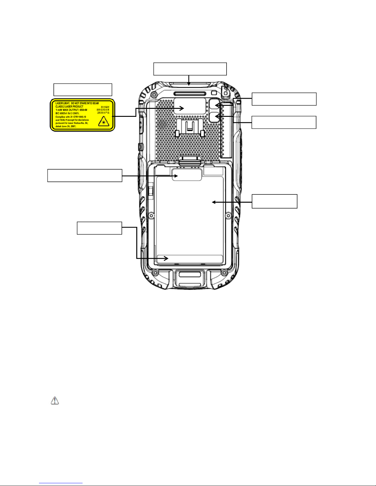
The laser light is visible to the human eye and is emitted from the window indicated in the figure.
ATTENTION
Un laser de classe 2 reste inoffensif pour les yeux. Le réflexe de clignement de l’œil limite l'exposition à 0,25 secondes au
plus. Ceci s’applique uniquement aux lasers de lumière visible (400-700 nm). Les Lasers de Classe 2 sont limités à 1 mW
(onde continue), ou davantage si le temps d'émission est inférieur à 0,25 secondes ou encore si la lumière n'est pas
cohérente dans l'espace. Bien que le fait de regarder directement le faisceau laser ne cause pas de dommage biologique
momentané, il est conseillé d’éviter de regarder le faisceau ainsi que n'importe quelle source de lumière très forte, comme
le soleil. Évitez également que le faisceau laser frappe l'œil d'un observateur, ainsi que toutes surfaces réfléchissantes
Page 9
8
environnantes, telles que des miroirs, etc
La lumière laser est visible pour l'œil humain et est émise à partir de la fenêtre indiquée sur la figure.
If the above laser light label is attached to your device, it indicates the product contains a
laser engine or laser aimer that emits the laser light. The following information is provided to
comply with the rules imposed by international authorities and refers to the correct use of
PM60 handy terminal.
Laser Safety Statement
This product has been tested in accordance with and complies with CDRH 21 CFR 1040.10 and
1040.11 and IEC 60825-1 Ed 2 (2007) except for deviations pursuant to Laser Notice No 50, dated
June 24, 2007. LASER LIGHT. DO NOT STARE INTO BEAM. CLASS 2 LASER PRODUCTS. 1 mW MAX
OUTPUT: 650nm.
For installation, use and maintenance, it is not necessary to open the device.
WARNING:
Do not attempt to open or otherwise service any components in the optics cavity. Opening or servicing
any part of the optics cavity by unauthorized personnel may violate laser safety regulations. The optics system
is a factory only repair item.
AVERTISSEMENT : Ne tentez pas d'ouvrir ou d’intervenir de quelque manière que ce soit sur les composants de la
cavité optique. L'ouverture ou l'entretien d'une partie de la cavité optique par des personnes non autorisées pourrait
enfreindre les règlementations liées aux normes de sécurité laser. La réparation du système optique ne peut être
prise en charge que par le personnel qualifié du fabricant.
Laser output window
Flash window
Camera window
S/N label
Window mobile label
IMEI label
Laser Light Label
Page 10

9
WARNING:
Use of controls or adjustments or performance of procedures other than those specified herein may
result in exposure to hazardous visible laser light.
AVERTISSEMENT : Toute manipulation, réglage, ou l'exécution des procédures autres que ceux spécifiés ici
peuvent entraîner une exposition dangereuse à la lumière visible du laser.
WARNING:
Use of optical systems with the scanner will increase eye hazard. Optical instruments include binoculars,
microscopes, eye glasses and magnifying glasses.
AVERTISSEMENT : L'utilisation du scanner avec des systèmes optiques tels que jumelles, microscopes, lunettes
de vue et autres loupes, augmente les risques de dommages pour les yeux.
2.4.
LED Safety
The LED output on this device has met IEC62471 LED safety and certified to be under the limits of a
CLASS 1 LED product.
2.5.
FCC/EU RF Exposure
This device complies with FCC/EU RF exposure guidelines set forth for an uncontrolled environment.
For body worn operation, this device has been tested and meets the RF exposure g uidelines for use
with an accessory thatcontains no metal and the positions the handset a minimum of 1.5 cm from the
body. Use of other enhancements may not ensure compliance with RF exposure guidelines. If you do
not use a body-worn accessory and are not holding the device at the ear, position the handse t a
minimum of 1.5 cm from your body when the device is switched on.
2.6.
CB Scheme
This device complies with CB Scheme IEC 60950-1
2.7.
FCC Part 15 Regulation
Pursuant to part 15 of the FCC Rules, you are cautioned that changes or modifications not expressly
approved by Pointmobile could void your authority to operate the PM60 handy terminal.
This device complies with part 15 of the FCC Rules. Operation is subject to the following two conditions:
(1) This device may not cause harmful interference, and (2) this device must accept any interference
received, including interference that may cause undesired operation.
This device has been tested and found to comply with the limits for a Class B digital device, pursuant
to Part 15 of the FCC Rules. These limits are designed to provide reasonable protection against harmful
interference in a residential installation. This equipment generates uses and can radiate radio
frequency energy and, if not in stalled and used in accordance with the instructions, may cause harmful
interference to radio communications. However, there is no guarantee that interference will not occur
in a particular installation. If this equipment does cause harmful interference to radio or televisi on
reception, which can be determined by turning the equipment off and on, the user i s encouraged to
try to correct the interference by one or more of the following measures:
• Reorien t or relocate the receiving antenna.
• Increase the separation between the equipment and receiver.
• Conn ect the equipment into an outlet on a circuit diff erent fr om that to which the receiv er is
connected.
• Consult the dealer or an experienced radio/TV technician for help.
Page 11
10
In accordance with FCC 15.21, changes or modifications not expressly approved by the party
responsible for compliance could void the user‘s authority to operate the equipment.
The antenna(s) must not be co-located or operating in conjunction with any other antenn a or
transmitter. To maintain compliance with FCC/EU RF exposure guidelines for body-worn
operation, do not use accessories that contain metallic components. .
2.8.
Radio Compliance
PM60 RF terminals are in conformity with all essential requirements of the R&TTE Directive
(1999/5/EC).
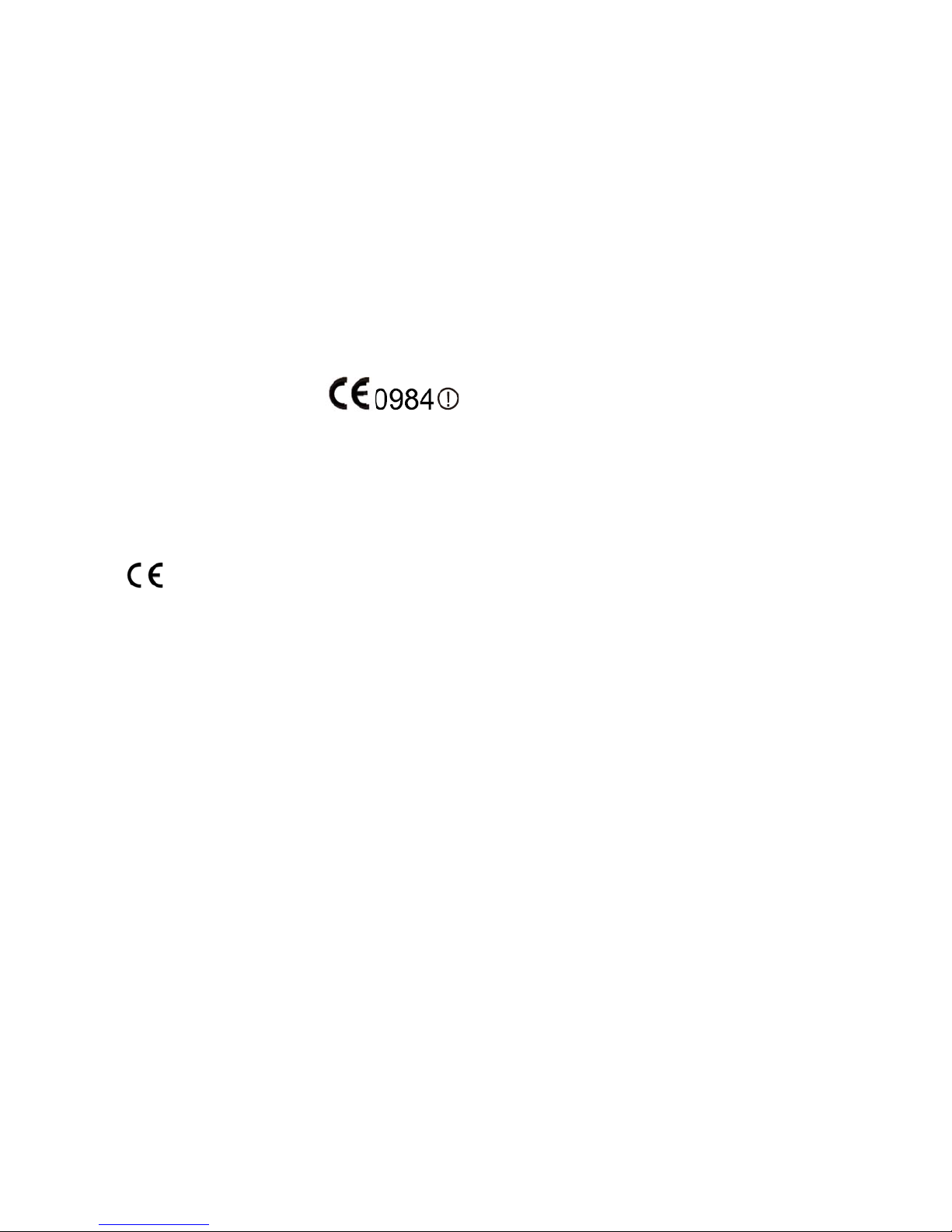
This device is marked with in accordance with the Class II product requirements
specified in the R&TTE Directive, 1999/5/EC. The device is intended for use throughout the European
Community; PAN European Frequency Range: 2.402 ~ 2.480 GHz.
Restrictions for use in France are as follows:
• Indoor use: maximum power (EIRP*) of 100 mW for the entire 2.400 ~ 2.4835 GHz
• Outdoor use: Maximum power (EIRP*) of 100 mW for the 2.400 ~ 2.454 GHz band and
maximum power (EIRP*) of 10 mW for the 2.454 ~ 2.483 GHz band.
The CE mark on the device indicates that the system has been tested to and confirm with the
provisions noted within the 2004/108/EC Electromagnetic Compatibility Directive and the
2006/95/EC Low Voltage Directive,
1999/5/EC (R&TTE), and 2011/65/EU (RoHS)
.
Pointmobile shall not be responsible for use of our product with equipment (i.e., power
supplies, personal computers, etc.) that is not CE marked and does not comply with the Lo w
Voltage Directive.
2.9.
WWAN
In radio systems configured with mobile computers and access points, the frequencies to be used
must be allowed by the spectrum authorities of the specific country in whi ch the installation takes
place. Be absolutely sure that the system frequencies are correctly set to be compliant with the
spectrum requirements of the country. The Radio modules used in this product automatically adapt
to the frequencies set by the system and do not require any parameter settings .The TYPE field shows
the correspondence between PM60 types and radio modules:
HSPA+
HSPA+, or Evolved High-Speed Packet Access, is a technical standard for wireless, broadband
telecommunication. HSPA+ enhances the widely used WCDMA (UMTS) based 3G networks with higher
speeds for the end user.
2.10.
WEEE Compliance
Information for the user in accordance with the European Commission Directive
2012/19/EU of the European Parliament and of the Council of 4 July 2012 on Waste
Electrical and Electronic Equipment (WEEE)
This product has required the extraction and use of natural resources for its production. It may contain
hazardous substances that could impact health and the environment, if not properly disposed. In
order to avoid the dissemination of those substances in our environm ent and diminish the pressure
Page 12
11
on the natural resources, we encourage you to reuse, recycle and recover the product. If the product
is disposed according to the Directive, it will avoid potentially negative consequences to the
environment and human health which otherwise could be caused by incorrect disposal.
The product marked with crossed out wheeled bin must be disposed separately from municipal
waste.
For more detailed information about disposal, reuse, and recycle system, contact your local or regional
waste administration.
3. Getting Started
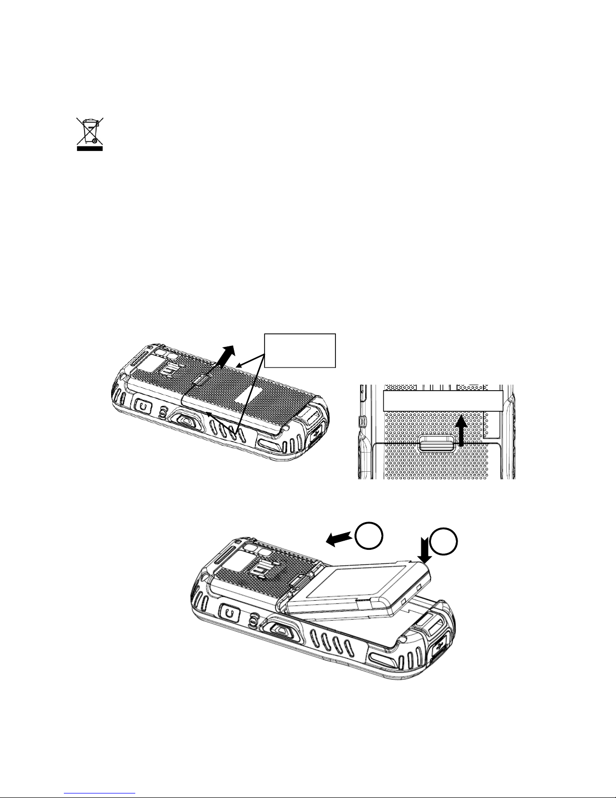
3.1. Install the Battery
The HANDY TERMINAL is shipped with the battery packaged separate from the unit. Follow the
steps below to install the battery.
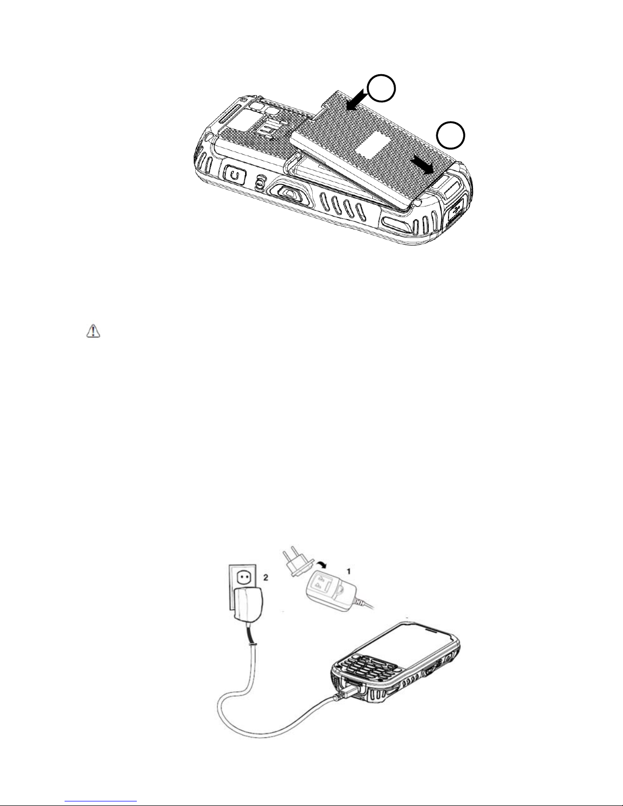
1. Remove the battery compartment door by moving the Battery door’s locks up.
2. Insert the battery well with the battery cells facing top.
3. Replace the battery door to start from bottom to top door’s lock downwards.
Battery door lock Up
1
2
Rib of
hanging
Page 13
12
☞
NOTE:
Two points of Battery guide stopper must be pertinently inserted to rear cover battery guide stopper hole
☞
NOTE:
The battery door must be installed prior to booting the unit.
WARNING:
Use only Pointmobile-approved Li-Ion battery packs. Unauthorized battery may result in damage not
covered by the warranty.
AVERTISSEMENT : Utilisez uniquement des batteries Lithium-Ion approuvés par Pointmobile. Toute autre batterie peut
entraîner des dommages non couverts par la garantie.
3.2.
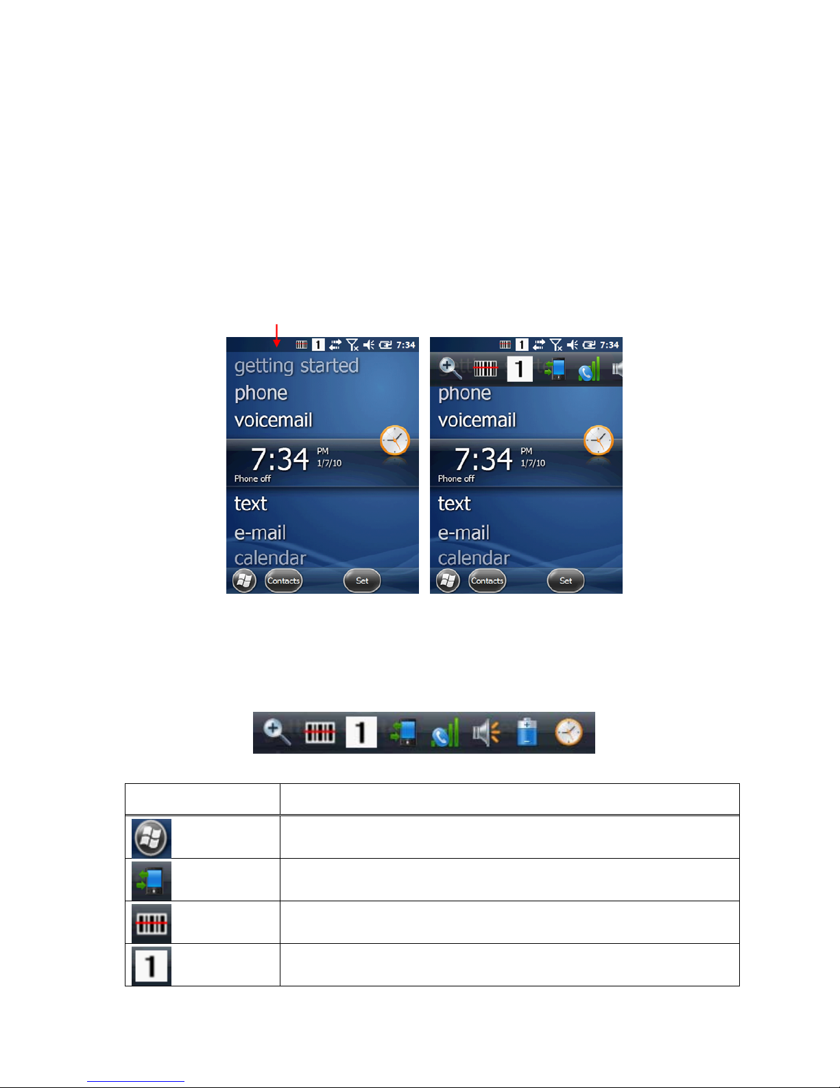
Charge the Batteries
Handy Terminals ship with only main battery pack significantly charged of power. Charge the main
battery pack with the Handy Terminal charging cable for a minimum of 4 or 6 hours depending
on your battery before initial use.
1. Attach the appropriate plug adapter to the plug of the power cable.
2. Insert the plug into the appropriate power source.
Plug the Handy Terminal power cable into the USB Jack on the side end of the unit.
1
2
Page 14

13
WARNING:
Use only Pointmobile-approved peripherals, power cables, and power adapters. Unauthorized
peripherals, cables, or power adapters may cause batteries to explode or damage your device.
DO NOT attempt to charge damp/wet handy terminals or batteries. All components must be dry before connecting
to an external power source.
Batteries must be charged at a temperature ranging from 0~45℃ (±3℃). If you don’t follow the guide, it might
have a harmful effect on the battery life.
AVERTISSEMENT : Veillez à n’utiliser que les périphériques approuvés par Pointmobile (câbles d'alimentation et
adaptateurs électriques). Tout périphérique non autorisé (câble ou adaptateur) peut provoquer l’explosion de la
batterie ou endommager votre appareil.
NE PAS tenter de recharger les terminaux ou les batteries encore humides lorsqu’ils ont été mouillés. Tous les
composants doivent être impérativement séchés avant la connexion à une source d'alimentation externe.
Les batteries doivent être chargées à une température allant de 0~45°C (± 3°C). Le non-respect de ces
recommandations pourrait avoir un effet néfaste sur la durée de vie de la batterie.
CAUTION:
After the battery has been charged, disconnect the DC Power Jack from the terminal. If you stay on
that plug in use, it is possible to break the power code.
ATTENTION: Après une période de charge de la batterie, veillez à débrancher le connecteur du chargeur. Une
utilisation prolongée de celui-ci risquerait d’endommager le cordon d’alimentation.
☞
NOTE:
Rechargeable battery packs are not initially charged. Therefore the first operation to perform is to charge
them.
☞
NOTE:
If you remove the battery pack or it completely discharges, you have 30 minute window of time to insert a
charged battery pack before the battery completely discharges.
3.3.
LED Indicators
The red LED is ON while charging the battery and the green LED is ON when the battery is fully
charged.
Alternatively, it is also possible to recharge the battery pack by using the single slot cradle, the single
Ethernet cradle or the 4-slot battery charger.
During the charging process the LED positioned at the upper side of the display is red constant. Once
the charging process has been completed this LED is green constant.
If the battery pack is removed from the handy terminal, it can be recha rged by inserting it into the
rear slot of the single slot cradle, the single Ethernet cradle or the 4-slot battery charger.
3.4.
Guidelines for Battery Pack Use and Disposal
The following are general guidelines for the safe use and disposal of batteries:
Store the terminal and the spare batteries between 20 to 30 ºC (68 to 86 ºF) in order to
maintain optimal battery performance.
Standard batteries must be charged at a temperature ranging from 0 to 45℃ (±3℃).
The battery level may not be displayed correctly for some minutes after the disconnection if
the handy terminal is disconnected from power supply before the charging cycle is completed.
The handy terminal could get warm during charging. This is normal and does not mean a
malfunction.
To achieve the best battery life, turn off the radios not in use.
Page 15

14
Rechargeable battery packs is not initially charged. Therefore the initial operation to perform is
to charge them. See below.
By default, the battery pack is disconnected at the factory to avoid damage due to excessive
draining. Annual replacement of rechargeable battery pack avoids possible risks or
abnormalities and ensures maximum performance.
WARNING:
DO NOT attempt to charge damp/wet handy terminals or batteries. All components must be dry
before connecting to an external power source.
AVERTISSEMENT : NE PAS tenter de recharger les terminaux ou les batteries encore humides lorsqu’ils ont été
mouillés. Tous les composants doivent être impérativement séchés avant la connexion à une source d'alimentation
externe.
WARNING:
Never throw a used battery in the trash. It contains heavy metals and should be recycled according
to local guidelines.
AVERTISSEMENT : Ne jetez pas une batterie usagée à la poubelle. Elle contient des métaux lourds et doit être
recyclée conformément aux directives locales.
WARNING:
Storage of batteries for long time at fully charged status or at fully discharged status should be
avoided.
Only in case of long storage, in order to avoid deep discharge of the battery, it's recommended to partially
recharge the battery every two-three months to keep the charge status at a medium level.
AVERTISSEMENT : Le stockage des batteries (à pleine charge ou complètement déchargée) pendant de longues
durées doit être évité.
Pour éviter une décharge profonde de la batterie en cas de stockage de longue durée ; il est recommandé de
recharger partiellement la batterie tous les deux à trois mois pour maintenir l'état de charge à un niveau moyen.
WARNING:
Installing, charging and/or any other action should be done by authorized personnel and following
this manual.
The battery pack may get hot, explode, ignite, and/or cause serious injury if exposed to abusive conditions.
If the battery pack is replaced with an improper type, there is risk of explosion.
Do not place the battery pack in or near a fire or heat; do not place the battery pack in direct sunlight, or use or
store the battery pack inside unventilated areas in hot weather; do not place the battery pack in microwave ovens,
dryer, high pressure containers, on induction cookware or similar device. Doing so may cause the battery pack to
generate heat, explode or ignite. Using the battery pack in this manner may also result in a loss of performance
and a shortened life expectancy.
Use only a Pointmobile approved power supply. The use of an alternative power supply will void the product
warranty, may cause product damage and may cause heat, explode or ignite.
The area in which the units are charged should be clear of debris and combustible materials or chemicals.
Do not use the battery pack in any other manner outside its intended use in Handy Terminal and peripherals.
AVERTISSEMENT : L’installation, la charge et/ou de toute autre action doit être effectuée par du personnel autorisé
après lecture de ce manuel.
En cas d'utilisation dans des conditions abusives, la batterie peut chauffer, exploser, s'enflammer et/ou causer des
blessures graves.
L’utilisation d’une batterie inappropriée peut résulter un risque d’explosion
N’exposez pas la batterie au feu ou près d’une source de chaleur; ne placez pas la batterie en plein soleil.
Par temps chaud, n’utilisez ou ne stockez pas la batterie dans des zones non ventilées.
Ne placez pas la batterie dans un four à micro-ondes, un sèche-linge, un conteneur à haute pression, sur une
batterie de cuisine à induction ou tout dispositif similaire. La batterie pourrait chauffer, exploser, s'enflammer ou
entraîner une perte de performance avec pour conséquence une espérance de vie réduite.
N’Utilisez que le bloc alimentation fourni et approuvé par Pointmobile. L'utilisation de tout autre alimentation pourrait
engendrer des dommages au produit et provoquer une surchauffe, allant jusqu’à l’explosion ou l'enflammement, et
causer la perte de la garantie.
Le local dans lequel les terminaux sont rechargés doit être propre et sans aucune présence de matériaux
Page 16

15
combustibles ou de produits chimiques.
Ne pas utiliser la batterie en dehors de l’utilisation prévue pour le terminal portable.
WARNING
Do not short-circuit the battery pack contacts connecting the positive terminal and negative terminal. This might
happen, for example, when you carry a spare battery pack in your pocket or purse; accidental short–circuiting can
occur when a metallic object such as a coin, clip, or pen causes direct connection of the contacts of the battery
pack (these look like metal strips on the battery pack). Short–circuiting the terminals may damage the battery pack
or the connecting object.
Do not apply voltages to the battery pack contacts.
Do not pierce the battery pack with nails, strike it with a hammer, step on it or otherwise subject it to strong
impacts or shocks.
Do not disassemble or modify (i.e. bend, crush or deform) the battery pack. The battery pack contains safety and
protection devices, which, if damaged, may cause the battery pack to generate heat, explode or ignite.
In case of leakage of liquid from the battery, avoid contact with liquid the skin or eyes. If the contact occurs,
immediately wash the affected area with water and consult a doctor.
Do not solder directly onto the battery pack.
Do not expose the battery pack to liquids.
Avoid any knocks or excessive vibrations. If the device or the battery is dropped, especially on a hard surface,
you should take it to the nearest Authorised Repair Centre for inspection before continuing to use it.
Do not replace the battery pack when the device is turned on.
Do not remove or damage the battery pack’s label.
Do not use the battery pack if it is damaged in any part.
Battery pack usage by children should be supervised.
Collect and recycle waste batteries separately from the device in comply with European Directive 2006/66/EC,
2011/65/EU, 2012/19/EU and subsequent modifications, US and China regulatory and others laws and regulations
about environment.
AVERTISSEMENT : Ne mettez pas les contacts de batterie en court-circuit en connectant la borne positive et la
borne négative. Cela peut se produire, par exemple, lors du transport d’un pack de batterie de rechange dans votre
poche ou un sac. Un court-circuit accidentel peut se produire si un objet métallique provoque la connexion directe
des contacts de la batterie. Un court-circuit risque d'endommager la batterie ou l'élément de connexion.
Ne pas appliquer de tension sur les contacts de batterie.
Ne pas percer la batterie avec des objets pointus, la soumettre à l’écrasement ou à des chocs violents.
Ne pas démonter ou modifier la batterie (en la pliant, l’écrasant ou la déformant). Celle-ci contient des dispositifs
de sécurité et de protection, qui, s'ils sont endommagés, peuvent entraîner un échauffement excessif allant jusqu’à
provoquer, son explosion ou son enflammement.
En cas de fuite du liquide contenu dans la batterie, évitez tout contact sur la peau ou les yeux. Si toutefois un
contact se produit, lavez immédiatement la zone affectée avec de l'eau et consulter un médecin.
Ne pas souder directement sur la batterie.
Ne pas exposer la batterie à des liquides.
Eviter les chocs et les vibrations excessives. En cas de chute du terminal ou de sa batterie, en particulier sur une
surface dure, il est instamment demandé de contacter le centre de réparation agréé le plus proche pour inspection
et vérification de son état normal de fonctionnement.
Ne pas remplacer la batterie lorsque l'appareil est allumé.
Ne pas retirer ou endommager l'étiquette de la batterie.
Ne pas utiliser la batterie si elle est endommagée d’aucune manière que ce soit.
L’utilisation d’une batterie rechargeable par des enfants doit être supervisée par un adulte.
La Collecte et le recyclage des piles et batteries doit être faite en conformité avec la directive européenne 2006/66
/ CE 2011/65 / UE 2012/19 / UE et ses modifications ultérieures. Elle doit également répondre aux lois et
réglementations sur l’environnement, en vigueur aux Etats-Unis et en Chine
☞NOTE:
In order to guarantee an adequate operating autonomy, when replacing the battery pack the handy
terminal checks the battery energy level. If the battery is not sufficiently charged, handy terminal does not turn on.
In this case, either substitute the battery pack with a charged one (sufficiently charged) or insert handy terminal into
a powered cradle or plug it into the direct power supply.
Page 17
16
3.5. Turn Your Device On
If you apply the power to your device, it turns on by itself. Do NOT press any keys or interrupt while
turning on process.
When the process is complete, the Desktop appears, and the terminal is ready for use.
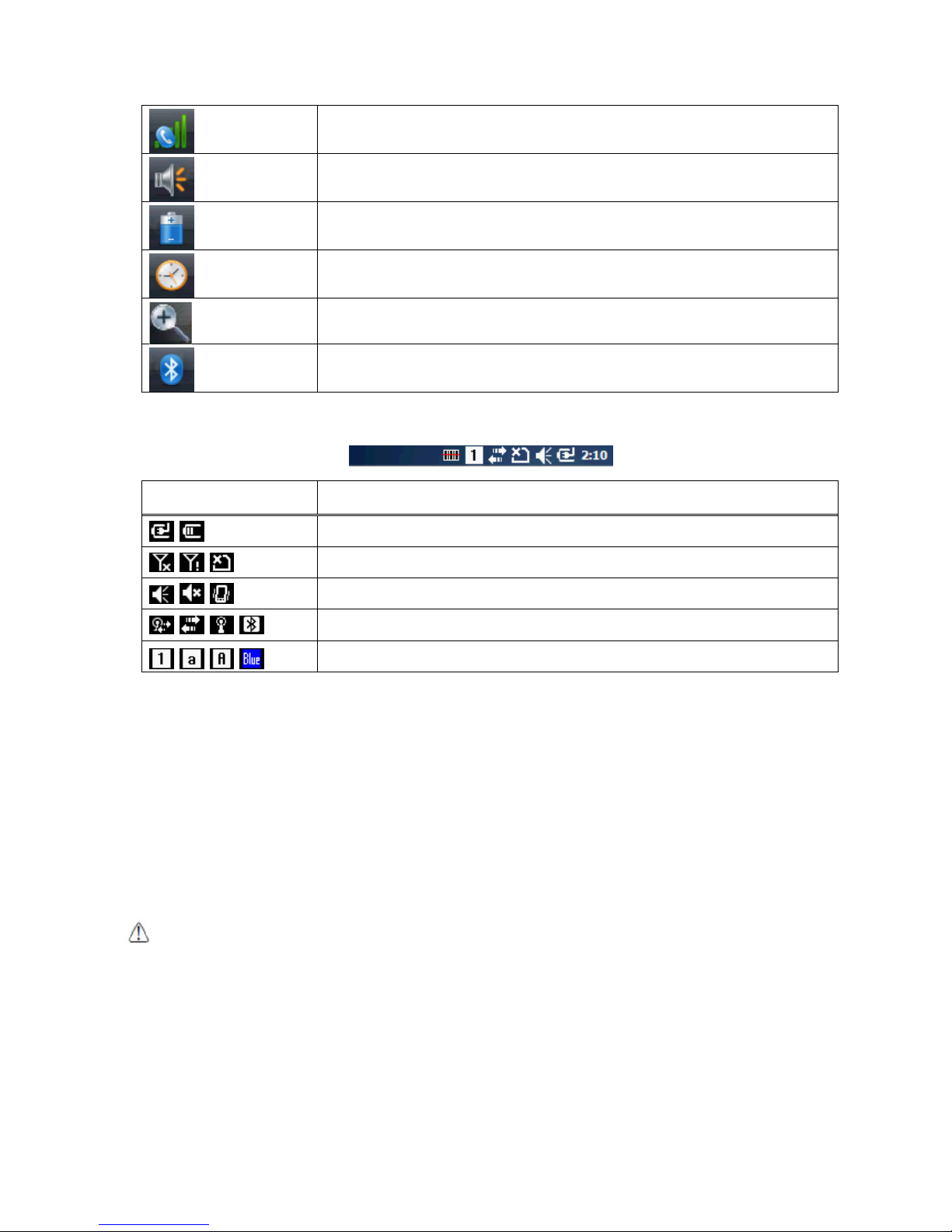
3.6. Desktop
☞NOTE:
You can access the Desktop any time by tapping the Change Views icon in the command bar and selecting
Desktop on the popup menu
Tap the touch screen once to zoon in the upper menu
3.7. Indicator Icons
The command bar, located at the upper of application screens, provides access to many system
functions and programs.
Icons Meaning
Open the start menu
Access the Wireless Manager
Open the Scanner option menu
Indicates the Keypad value
Page 18
17
Shows phone signal mode
Shows the volume
Indicates the Battery Control Panel (CPL)
Indicates Clock & Alarm CPL
zoom in/ out
Access the Bluetooth radio
Left and right arrows are used to scroll through additional icons
Icon Meaning
Indicates AC connection mode
Indicates WAN (Phone) connection mode
Indicates Sound connection mode
Indicates LAN / Bluetooth mode
Indicates Keypad mode
3.8.
Using the Stylus
The terminal comes with a stylus included in a loop on the Lanyard. Use this stylus (or your finger)
to select or enter information on the touch screen. The stylus functions as a mouse; generally, a tap
is the same as a click.
Tap Tap the touch screen once to open menu items and select options.
Drag Hold the stylus on the screen and drag across the screen to select text and images.
Tap & hold Tap and hold the stylus on an item and a pop-up menu appears. On the pop-up menu, tap
the action of the task you want to perform.
WARNING:
Use of objects, such as paper clips, pencils, or ink pens on the touch screen can damage the input
panel and may cause damage not covered by the warranty.
AVERTISSEMENT : L'utilisation d'objets, tels que trombones, crayons, stylos à encre sur l'écran tactile peut
l’endommager et causer des dommages non couverts par la garantie.
3.9.
Selecting Program
Tap Start -> Programs. To open a program, tap the icon on the menu.
Page 19

18
3.10. Pop-Up Menus
You can quickly choose an action for an item using the pop-up menus.
1. Tap and hold the stylus on the item name. The pop-up menu appears.
2. Lift the stylus and tap the action you want to perform.
The contents of pop-up menus change according to the program you are using.
3.11. Using Windows Explorer
Use Windows Explorer to navigate through the files on your system. Start menu -> File explorer
Move files by tapping and holding on the file, and then tapping Cut, Copy or Paste on the pop-up
menus that appear.
4. Get to Know Your Device
4.1. Feature of Your Device
The following list outlines a few of the feature included in your device.
4.2. PM60 Handy Terminal
Operating Systems: Microsoft Windows Embedded Pointmobile 6.5 Pro
Micro Processor: Cortex-A8 1GHz
RAM Memory: 512MB
FLASH Memory: 1GB
3.5” VGA Display: 480x640 Transmissive TFT
Industrial Grade Touch Screen
Keyboards: Numeric, Qwerty
Micro SDHC Expansion Memory Card Interface: Support up to 32 GB
Power Supply : MicroUSB power adaptor
Interfaces : Micro-USB connector : USB 2.0 High Speed
HandyLink connector: USB 2.0 High speed Client, Host (USB Host for Ethernet Cradle),
Charging
Scan Engine:
• 1D engine: N4313, uE966
• 2D engine: N560X
Battery: Li-ion battery, 3.7V/4000mAh/14.8Wh
IP65 certified enclosures
Audio: Integral Microphone, Earpiece, Loud, Speaker, 3.5pi 4pole Jack for Ear-Mic headset
BT: Bluetooth Radio 2.1+EDR with Internal Antenna
WLAN: 802.11 b/g/n Radio with Internal Antenna
Notification LEDs
1) Power indications, 2) Scan reading indications & OS notifications
Notification Vibration Motor
Camera : 5M pixel CMOS camera with AutoFocus and LED flash
Sensors : Proximity sensor and Acceleration sensor
GSM/GPRS/EDGE : Quad band, 850/900/1800/1900MHz
Page 20
19
UMTS/HSPA+: Five band, 800/850/900/1900/2100MHz
GPS: Standalone and Assisted GPS
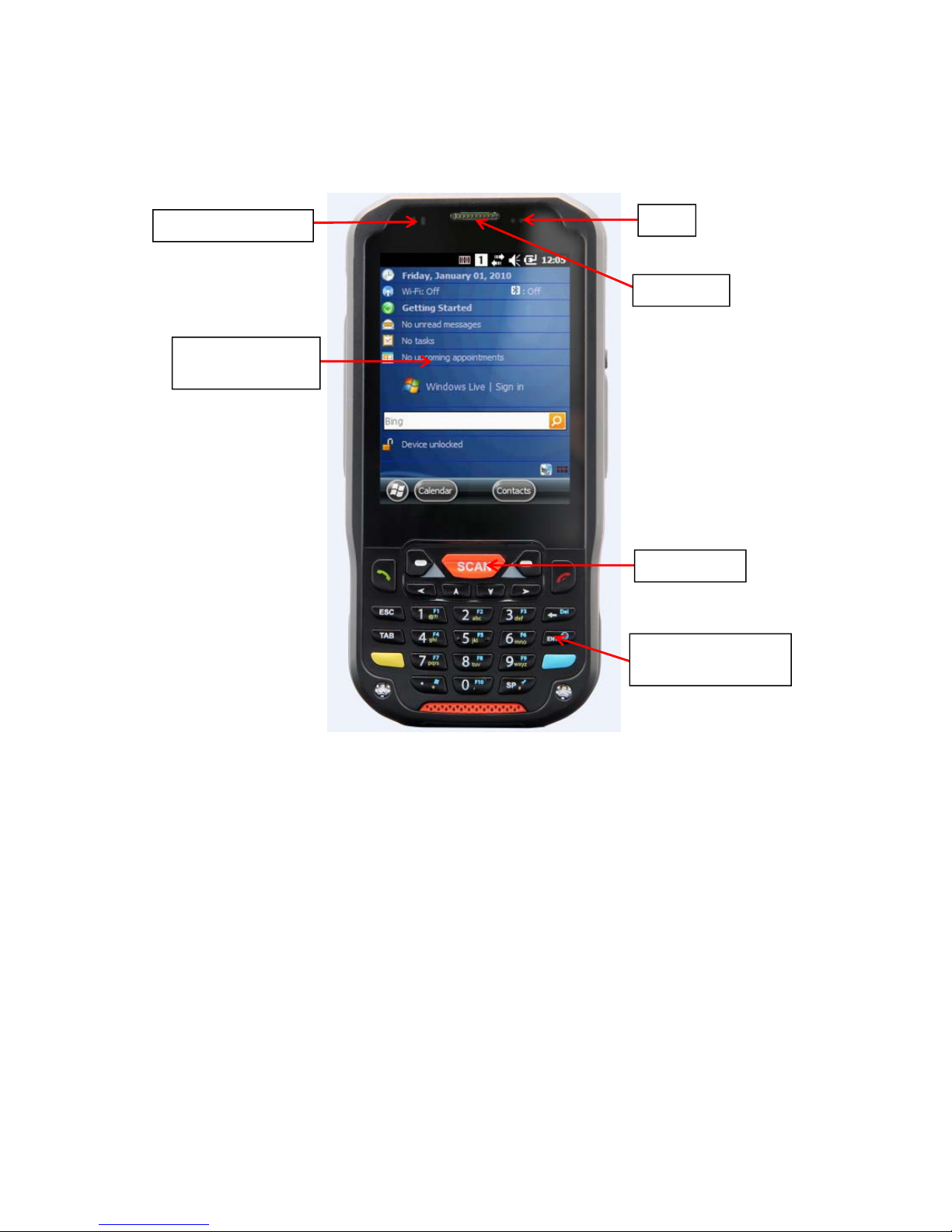
4.3. Front Panel Layout
LED Indicator
Shows the information needed to operate your device as follows:
Note: The LED is user-programmable.
LED Color Meaning
LED Color Meaning
Red Lights when main battery is charging.
Blinks, when the battery is very low (<10%),
Lights when the battery is low (<20%),
Blinks as Red/ Green
by turns when it is no battery or not recognized
Green Lights, when the PDA resets
Lights when main battery charging has completed.
Blinks as Red / Green
by turns when it is no battery or not recognized
Blue Lights when a scan Pass
Lights when PDA wakes up
Red Lights when a scan fails
Lights when PDA suspends
Red Lights when main battery is charging.
Touch screen
display
Proximity sensor
Receiver
LED
Scan key
Keyboard
(32-key numeric)
Page 21

20
Green Lights when scanned bar code is successfully decoded.
Lights when main battery charging has completed.
Blue Lights when a scan Pass
Red Lights when a scan fails
Keypad
32 numeric keypad (includes side scan and volume, power button).
55 qwerty keypad (includes side scan and volume, power button).
Microphone
The integrated microphone can be used for audio recording and phone call.
Touch Screen Display
The display is a LCD (Liquid Crystal Display) with a Capacity touch screen. The 3.5” VGA
(Video Graphic Array) is transmissive active matrix color and backlit. The resolution is 480 x
640; see Display Backlight on paragraph 4.4.
For touch screen input, use the stylus included with the terminal or your finger. The method
you choose depends on which one is most appropriate for your application. While there is a
great deal of variation in different applications, you generally achieve greater accuracy with
the stylus for buttons or icons that are close together.
WARNING:
Use of objects, such as paper clips, pencils, or ink pens on the touch screen can damage the input
panel and may cause damage not covered by the warranty.
AVERTISSEMENT : L'utilisation d'objets, tels que trombones, crayons, stylos à encre sur l'écran tactile peut
l’endommager et causer des dommages non couverts par la garantie.
4.4.
Display Backlight
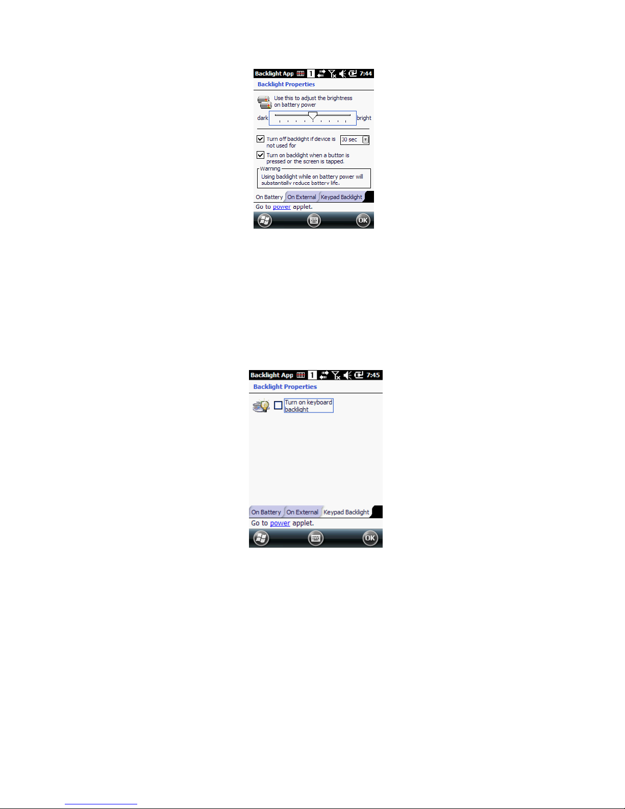
The intensity of the backlight of the touch screen display may be changed, and the backlight may
be programmed to turn off after the terminal has been idle for a specified period of time.
To adjust the intensity of the backlight while on battery power, tap Start -> Settings -> System -
> Backlight.
Screen Backlight - Battery/External Power
Move the slider to adjust the screen backlight while on battery power.
You may turn the screen backlight off if the device is not used for a designated period of time by
checking the option and designating the desired time period.
You may also turn on the screen backlight when a button is pressed or the screen is tapped by
selecting the appropriate checkbox.
Page 22
21
☞NOTE:
Using the backlight option while on battery power substantially reduces battery life.
You may make the same changes when on external power by tapping the External tab.
4.5. Keypad Backlight
To turn on the keypad backlight, check the checkbox.
The duration of backlight of keypad synchronizes with LCD backlight’s.
4.6. Using Screen Protectors
Pointmobile defines proper use of the terminal touch panel display as using a screen protector and
proper stylus. Screen protectors maintain the ongoing integrity (i.e., prevent scratching) of the
touch panel, which is why their use is recommended for applications that require a high to medium
level of interface with the touch panel.
Pointmobile also mandates use of the proper stylus, which is one that has a stylus tip radius of no
less than 0.8mm. Use of the stylus included with the terminal is recommended at all times.
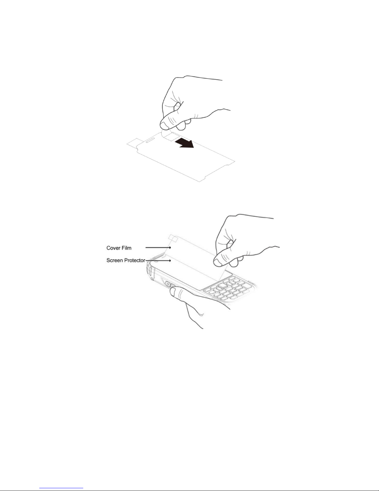
4.7. Installing Your Screen Protector
When installing a screen protector, use a flat plastic card (e.g., credit card) to apply the screen
protector smoothly and remove any air bubbles.
1. Press the Power key to put the terminal in suspend mode.
Page 23
22
2. Clean the touch panel thoroughly with a clean, non-abrasive, lint-free cloth, Make sure nothing
is on the touch panel.
3. Blue tag with backing film: Peel off this mask before application.
4. Align the exposed edge of the screen protector along the left edge of the touch panel.
Make sure that it lies flush with edges of the touch panel.
☞NOTE:
To reposition the screen protector, lift up gently and reapply.
5. Yellow tag with cover film:
“Please peel off this mask after application completed.
Page 24
23
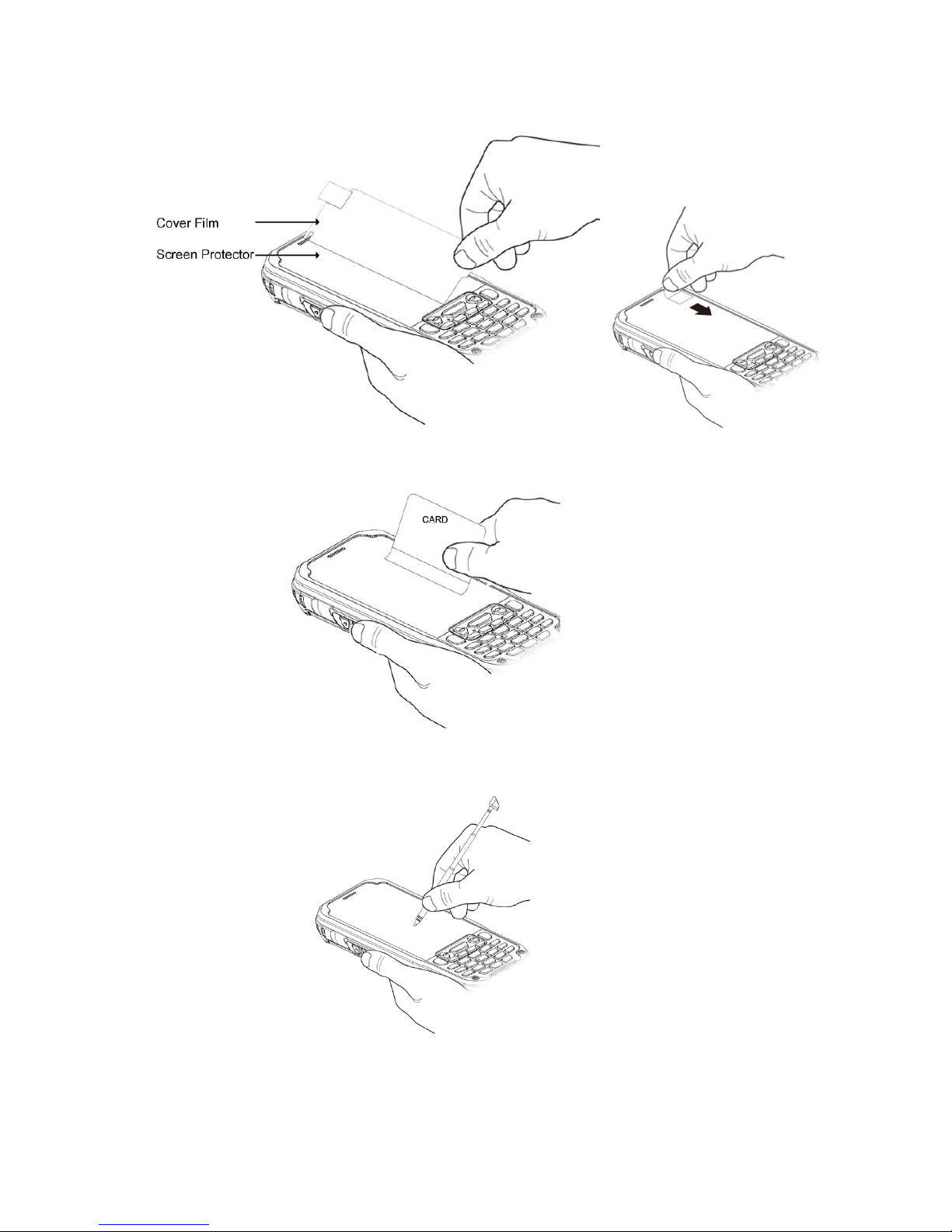
6. Press gently but firmly. Use the card a necessary to smooth out any air pockets or bumps after
alloation
7. Press the Power key to weak the terminal and check the touch panel with the stylus.
8. Verify that the screen accepts input from the stylus as usual. If not, re-apply the screen
protector.
9. Press the Power key to put the terminal back in suspend mode.
10. Clean the surface of the screen protector with a clean, non-abrasive, lint-free cloth.
11. Press the Power key to wake the terminal again.
Page 25
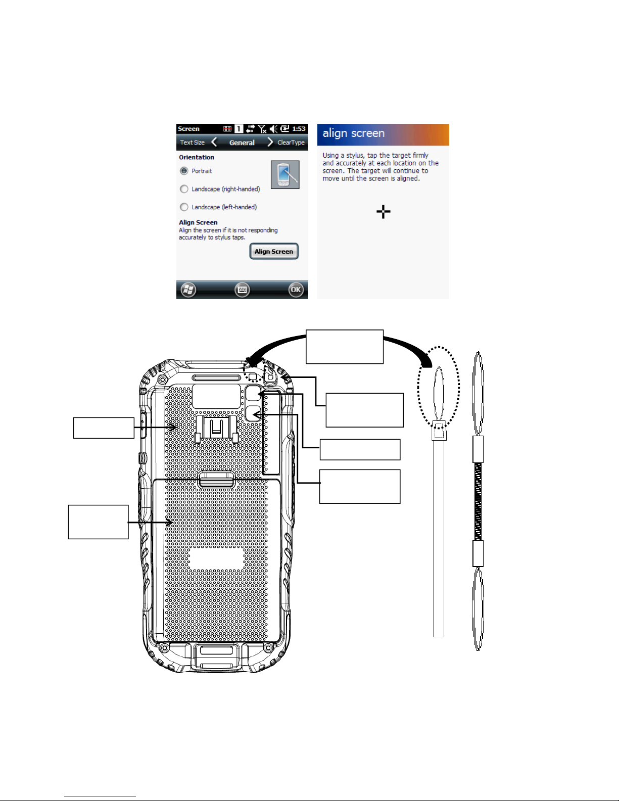
24
12. For maximum performance, recalibrate the screen Tap Start > Settings > System > Screen
13. Tap Recalibrate the follow the instructions on the screen.
4.8. Back Panel Layout
Wrist Lanyard
The HANDY TERMINAL comes with Wrist Lanyard. You can attach it to the device.
Hand strap
Battery
cover
LED window
Camera
window
Speaker
Wire spring
mount hole
Lanyard
mount hole
Page 26
25
The HANDY TERMINAL comes with Hand strap. You can attach it to the device.
Finger Saddle
This is a slightly depressed and angled area of the back housing that is designed to cradle
or “saddle” your finger while holding the terminal. This unique ergonomic design makes the
terminal comfortable to hold and helps prevent you from accidentally dropping the terminal.
Installed Battery
For information about installing the battery, see Install the Battery on paragraph 3.1.
For information about battery power, see Battery Power on paragraph 4.17.
Speaker
The integrated speaker sounds audio signals as you scan bar code labels and enter data,
but emits no ambient noise on system activity (i.e., processor, memory access, radio traffic,
etc.). The speaker can also be used for playing sounds (e.g., WAV or MP3 files).
The speaker meets the following SPL levels at 10cm:
• 500Hz–80dB
• 1kHz–90dB
• 4kHz–90dB
Stylus and tether
HANDY TERMINAL is shipped with a stylus inserted in a loop on the tether. Store the stylus
in the Lanyard when you’re not using it; see Using the Stylus on paragraph 3.8.
4.9.
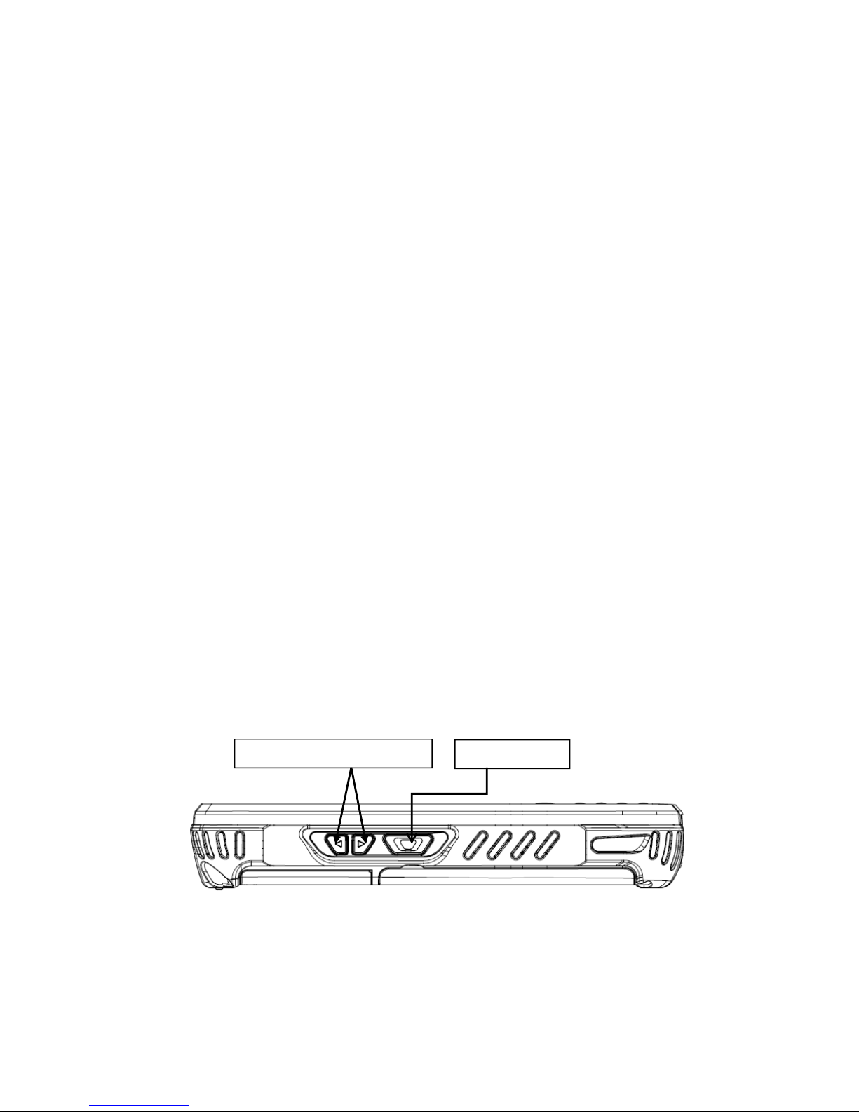
4.10. Left Side Panel Layout
Side Button
You can set the volume using the Volume Button and scan using the Scan button.
SCAN button
Volume Up/Down button
Page 27
26
4.11.
Installing Memory Cards
The HANDY TERMINAL supports Micro Secure Digital (SD) memory cards up to 32GB. Sandisk,
Kingstone and ATP micro SD recommended
To access the Micro SD card slot and insert the card, proceed as follows:
1. Press the Power key to put the terminal in Suspend Mode; see Suspend Mode on paragraph
4.23.
2. Remove the battery door on the back of the unit.
3. Remove the battery and open
4. Insert the SD card with the label facing upward.
☞
NOTE:
To remove an installed SD card tap on the edge lightly to unlock the card; the card will pop out just enough
for you to grab its edge and pull it out.
5. Tap the Power key to resume operation.
6. To verify that the operating system recognizes the new memory card, open Windows Explorer
and navigate to My Device
\
Storage Card.
WARNING:
Follow proper ESD precautions to avoid damaging the SD. Proper ESD precautions include, but are
not limited to, working on an ESD mat and ensuring that the operator is properly grounded.
Do not force the card. If you feel resistance, remove the card, check the orientation, and reinsert it.
Do not use the Micro SD card slot for any other accessories.
It is highly recommended to lock the card holder even if the card is not present.
AVERTISSEMENT : Suivez les précautions appropriées contre les décharges électrostatiques pour éviter
d'endommager la carte SD. Ces précautions comprennent, mais ne sont pas limités au travail sur un tapis de décharge
électrostatique avec l’assurance que l'opérateur est correctement relié à la terre.
Ne forcez pas lors de l’installation de la carte SD. Si vous sentez une résistance, retirez la carte, vérifiez son orientation et
réinsérer la.
Ne pas utiliser le lecteur de carte Micro SD pour d'autres accessoires.
Il est fortement recommandé de verrouiller le support de carte même si la carte n'est pas présente.
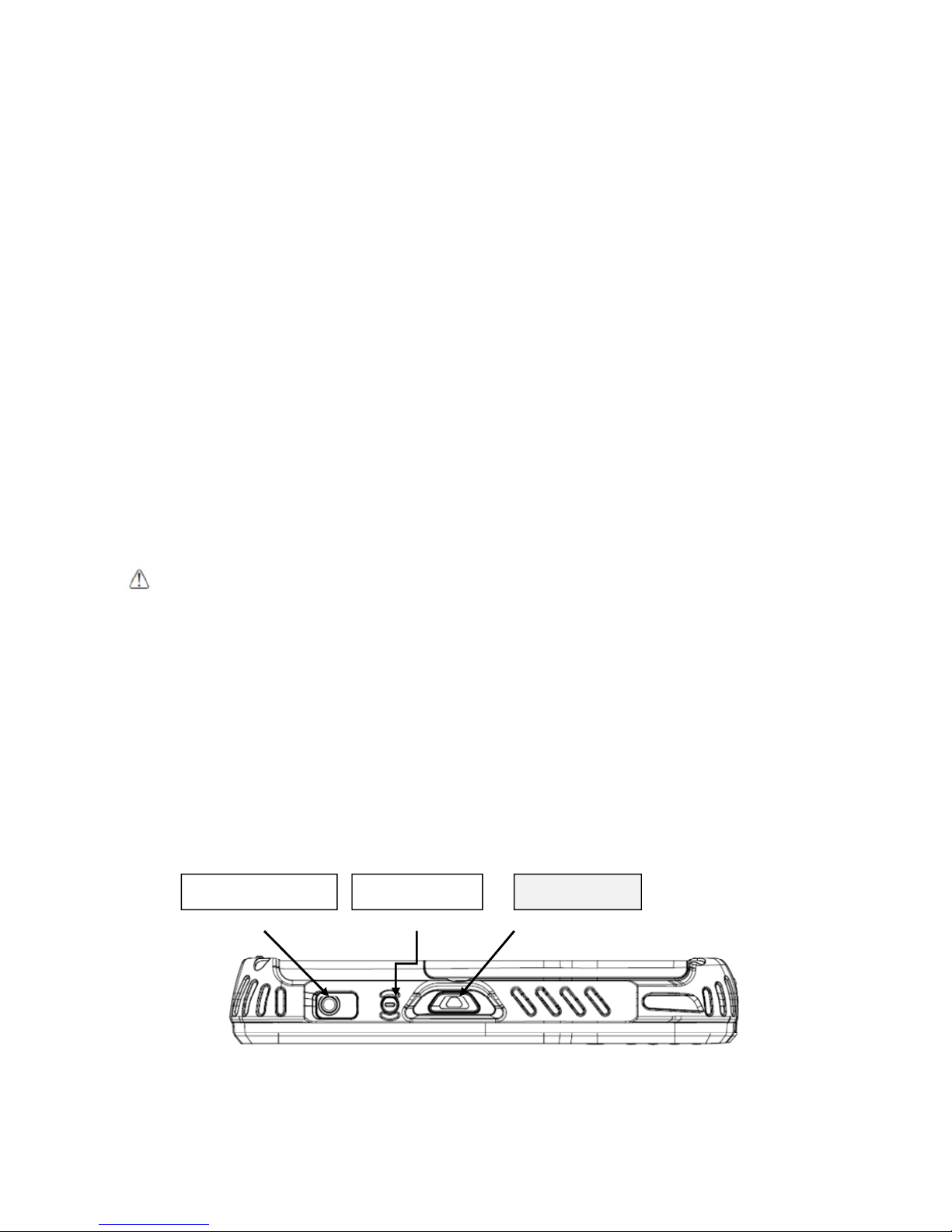
4.12.
Right Side Panel Layout
Side Button
You can use the Programs Buttons option in the Control Panel to change the functionality of
the side buttons. Scan function is assigned by default (Scan button).
Ear jack socket Scan button Power button
Page 28
27
EarJack
3.5pi 4pole Jack. This connector supports Ear-Mic headset
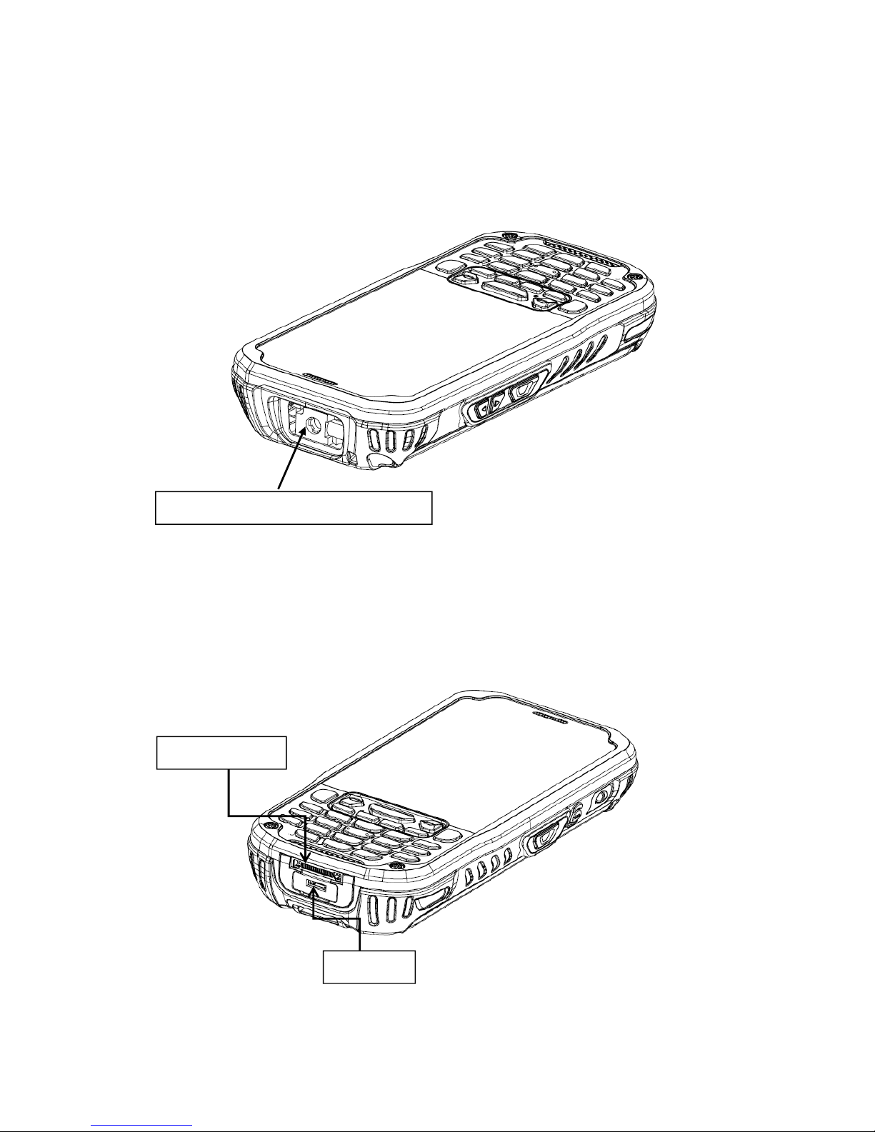
4.13. Top Panel Layout
Image Engine Window
The angled image engine reads and decodes most popular bar code symbolizes.
For more information, see Using the Image Engine on paragraph 6.
4.14. Bottom Panel Layout
HandyLink Connector
The HandyLink mechanical connector is designed to work exclusively with HANDY
TERMINAL peripherals and cables. This connector powers the terminal, charges the main
Image engine window (with engine)
I/O connector
USB port
Page 29

28
battery, and facilitates communication. This connector supports High speed USB 2.0
communication (up to 480 Mbps)
Through this connector, you can communicate with a host workstation via Microsoft
ActiveSync; see ActiveSync Communication on paragraph 10.4
The I/O connector supports the following signals:
Pin Description Direction
DC IN +5V IN
DC IN +5V IN
RS-232 Transmitted Data NC
GND
USB Host +5V Enable OUT
USB Host D+ IN/OUT
USB Host D- IN/OUT
USB Host Detect IN
GND
RS-232 Received Data NC
GND
GND
CRADLE Detect IN
USB Client D+
IN/OUT
USB Client D- IN/OUT
USB Client +5V IN
☞NOTE: Signals referenced are for a DTE device.
USB Port
This connector supports High speed USB 2.0 communication (up to 480 Mbps)
Also external power from the MicroUSB Adaptor that is included with the terminal. When
connected to the Handy Terminal MicroUSB Adaptor, the terminal is powered and the main
battery pack is charging.
4.15. Peripherals and Accessories
The following items are sold separately and enhance your HANDY TERMINAL’s capabilities.
Single Slot Cradle
This charging and communication cradle supports USB communication, enabling your terminal to
interface with the majority of enterprise systems. When a terminal is seated in a powered base, its
battery pack charges in five hours for the standard capacity 4000mAh pack.
For more information, see Single Slot cradle/Single Ethernet cradle Device on paragraph 12.
Single Ethernet Cradle
The Single Ethernet cradle is used to charge the battery, to power the battery charging system in
the terminal, and can be used to communicate data from the terminal to a PC/laptop via the
Page 30

29
Ethernet port.
For more information, see Single Slot cradle/Single Ethernet cradle Device on paragraph 12.
4.16. USB ActiveSync Cable
The MicroUSB ActiveSync Cable is used when communicating between the terminal and a host
computer to transfer data via the USB interface.
4.17. Li-ion Battery Packs
The Li-ion battery pack provides the main power supply for the terminal.
4.18. Battery Power
The intelligent battery technology inside the terminal features of battery power:
• The battery pack
The battery works to prevent data loss when the terminal is used over long periods of time.
The battery must be charged to full capacity before using the HANDY TERMINAL for the
first time!
Charge the main battery pack with the Handy Terminal charging cable for a minimum of 5 hours
depending on your battery before initial use.
4.19. Main Battery Pack
There are two Li-ion battery packs available for the HANDY TERMINAL:
Standard Capacity: Li-ion 3.7V/4000mAh/14.8Wh
The Li-ion battery pack is the primary power source for the Handy Terminal as well as for the
internal backup battery.
Changing the Main Battery Pack
Before installing a battery pack, press the Power key to put the terminal in Suspend Mode so that
operations are suspended before removing the main power source. Always put the terminal in
Suspend Mode prior to changing the battery. The HANDY TERMINAL is shipped with the battery
separate from the unit. You will need to loosen the Lanyard, remove the battery door, insert the
battery, and replace the battery door.
☞NOTE: The battery door must be installed prior to booting the unit.
Page 31
30
Charging Options
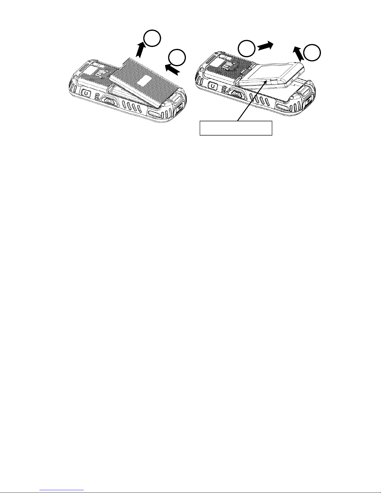
When the battery is installed in the terminal, you can use any of the peripherals listed below to
charge the battery.
• AC Power Supply to USB Port direct.
• Single slot docking cradle/Single slot Ethernet cradle
• Insert the battery in the spare battery charging well in the back of either the Handy Terminal slot
cradle or Handy Terminal Ethernet cradle.
Charging Time
The standard capacity 4000mAh Li-ion battery pack requires five hours to charge to full capacity.
4.20. Managing Main Battery Power
Data and files saved on the Handy Terminal may be stored in RAM memory; therefore, maintain a
continuous power supply to the terminal to help prevent data loss. When you remove a battery
pack, insert another charged battery pack in the Handy Terminal. If the main battery pack is low,
insert the terminal into a charging peripheral to power the terminal and begin recharging the
battery.
☞NOTE:
If the main battery is low and the terminal is in Suspend Mode, pressing the
Power
button does
not
wake
the HANDY TERMINAL; you must replace the discharged battery with a fully charged battery or apply AC power to
the terminal.
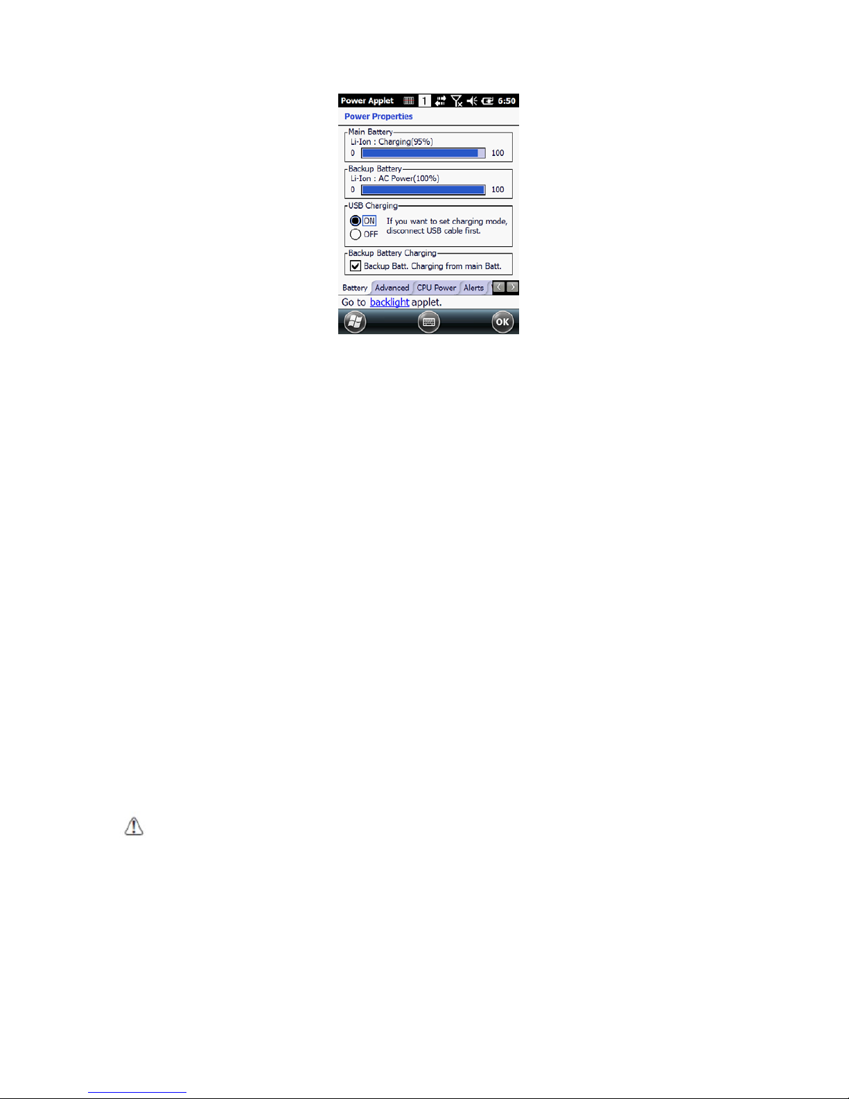
Checking Battery Power
Tap the battery icon to open the Power Properties. The Battery tab opens displaying the charge
status of the main battery
1
2
3
4
Main battery pack
Page 32
31
☞
NOTE:
You can also check battery power by tapping
Start -> Settings -> System -> Power
.
4.21.
Resetting the Terminal
There are three types of system resets: a Soft Reset, a Hard Reset, or a Factory Reset. The soft and
hard resets preserve all data stored in the file system. Contact a technical support representative for
more information on how to perform a Factory Reset.
Soft Reset (Warm Boot)
A soft reset re-boots the terminal without losing RAM data, terminates all running applications,
reloads the OS, and launches Autoinstall, which re-initializes any CAB or REG files in
\
AutoInstall\Cabfile folder.
You would perform a soft reset 1) when the terminal fails to respond, 2) after installing software
applications that require a reboot, or 3) after making changes to certain system settings, or 4) to
install new CAB or REG files.
To perform a Soft Reset:
1. Press the Power button for 3 seconds and choose the Soft Reset on the power menu .
2. When the reset is complete, the Desktop appears.
Hard Reset (Cold Boot)
CAUTION:
A hard reset erases all of the data and applications stored in RAM memory, reloads the
OS, and launches Autoinstall, which installs any CAB or REG files in the \AutoInstall\Cabfile.
ATTENTION : Une réinitialisation matérielle (hard reset) efface toutes les données et les applications stockées dans la
mémoire RAM du terminal. Elle charge à nouveau le système d'exploitation, et lance la procédure d’Autoinstall, qui installe
tous les fichiers CAB ou REG dans le répertoire \ AutoInstall \ CABFILE
Hard resets automatically launch a soft reset as part of the boot process if there are CAB files
present.
To Perform a Hard Reset:
1. Press the Power button for 3 seconds and choose the Hard Reset on the power menu.
Page 33
32
2. When the reset is complete, the Desktop appears.
To perform a Hard Reset if the terminal has stopped responding, press and hold the Power button
for 8 seconds until the terminal starts to re-boot.
4.22. Suspend Mode
Suspend Mode suspends terminal operation. The terminal appears to be “off” when in Suspend
Mode. The terminal is programmed to go into Suspend Mode automatically when inactive for a
specified period of time. You can set this time period in the Power setting.
To suspend and resume operation, press the Power button. You may also press the front Scan key
to wake a suspended device unless the battery door has been removed and replaced.
☞NOTE:
You should always put the terminal in Suspend Mode when you change the battery pack; see Changing the
Battery Pack on paragraph 4.18.
Troubleshooting Suspend/Resume
If the terminal does not wake when you press the Power button, the main battery might be too low
to resume operation. To check, remove the battery and install a fully charged battery or connect the
terminal to a Handy Terminal charging peripheral.
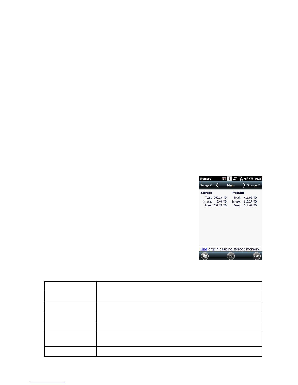
4.23. Memory Allocation
You can verify file storage and program memory in System Properties.
1. Tap Start -> Settings -> System -> Memory tab.
4.24. Care and Cleaning of the Products
When needed, clean the image engine window and the LCD display
with a clean, non-abrasive, lint-free cloth. The terminal can be
cleaned with a damp cloth.
4.25. PM60 Technical Specifications
Model PM60
Operating System Microsoft Windows Embedded Pointmobile 6.5 Pro
Application Software Tools and Demos
Processor Cortex-A8 1GHz
Memory 512MB RAM X 1GB Flash
Storage Expansion User accessible Micro SD memory card slot.
Display 3.5 in. transmissive active matrix 65K color LCD with backlight, VGA (480 x 640)
Page 34

33
Scan Engine
1D engine: N4313, uE966
2D engine : N560x
Keypad Numeric , Qwerty
Audio Built-in microphone and speaker
I/O High speed USB 2.0 from cradle (or I/O cable)
Battery Li-ion battery 3.7V / 4000 mAh / 14.8 Wh
Expected Hours of
Operation
8.5+ hours (with scan and continuously transmitting if using new standard Li-ion battery)
Charging 5V input through MicroUSB port.
Expected Charge Time Capacity: 4000mAh – approx. 5 hours
Charging Peripherals
MicroUSB Adaptor
Single Slot cradle–single-bay terminal charge/communicate
Single Ethernet cradle–single-bay terminal charge/communication base
(Via Ethernet connection)
Quad Battery Charger
WPAN Bluetooth Class II (10 m) v2.1 Enhanced Data Rate (EDR) with internal antenna.
WLAN Dual Mode 802.11 b/g/n (11 Mbps/54 Mbps) with internal antenna
WLAN Security
Wi-Fi Certified, 802.1X, WPA2, EAP, WEP, LEAP, TKIP, MSD, EAP-TLS, EAP-TTLS,
WPAPSK, PEAP, CCXv4
WWAN
GSM: Quad band, 850/900/1800/1900MHz
UMTS/HSPA+: Five band, 800/850/900/1900/2100MHz
GPS Assisted GPS
Operating
Temperature
-20° to 55°C
Charging Temperature
0~45℃ (±3℃))
Storage Temperature -25ºC to 70ºC
Humidity 95% humidity, non-condensing
Construction
High impact resistant PC/ABS housings
Magnesium alloy internal chassis with component shock mounts
Drop
1.22m multiple drops to concrete, MIL-STD-810G, Method 516.6, Procedure
Tumble 3.3 ft (1.0m) tumbles (500 drops)
ESD
Air: ± 15kV
Direct: ± 8kV
Environmental Independently certified to meet IP65 standards for moisture and particle resistance
Page 35
34
Dimensions
H; 157.4mm x W; 74.2mm x L; 25.8mm(top)
Weight
1) 1D ; 330g (239g with battery)
2) 2D ; 330g (239g with battery)
Scanner / Decode
Capabilities
1D Laser model: N4313 laser engine. Decodes all standard 1D codes.
2D engine model: N560X 2D Imager. Decodes all standard 1D, 2D, Postal, and OCR
codes.
5. Using the Keypad
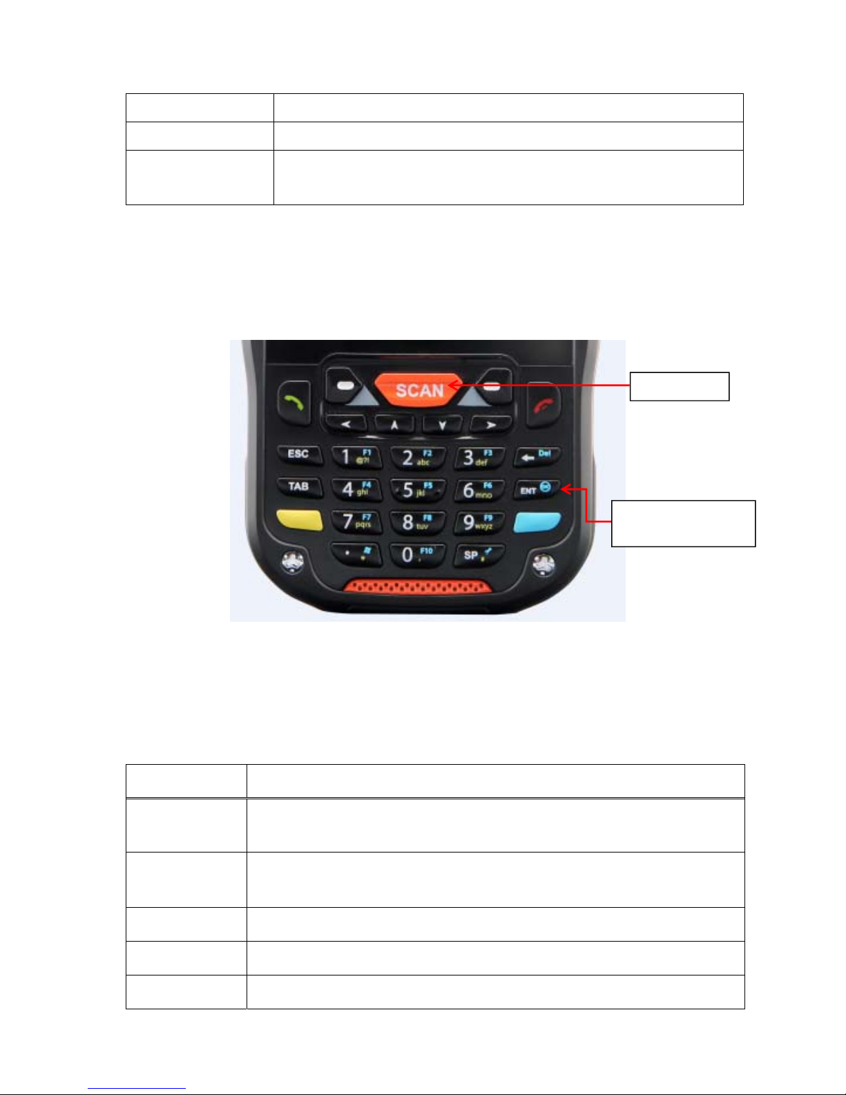
5.1. Numeric Keypad Layout
5.2.
Navigation Keys
Located in the center of the keypad for easy access with either hand, the navigation keys enable
you to move the cursor up and down lines and from character to character.
5.3. Basic Keys
Name Function
BLUE Modifies the next key pressed to type specific functions.
Yellow(ALPHA)
Toggles the keypad between alpha (upper and lowercase) and numeric modes.
Indicator changes accordingly on the command bar.
Send Begin dialing. Start an action.
End Hang up. Cancels an action.
ESC returns to closing stage of program and stage before
Keyboard
(29-key numeric)
Scan key
Page 36
35
Tab Moves to next control (Indent function to Text editor)
Backspace
Backspace moves the cursor back one space.
If you are typing text, a character is deleted each time you press the backspace
key.
Enter Performs the same function as the Enter key on a workstation.
Power Suspends and resumes the terminal.
Scan Activates the image engine to scan a bar code or take an image.
Soft(Left/Right) Button move of Task Bar of bottom (Left/Right)
5.4. Alpha/Numeric Modes
The keypad defaults to numeric mode. Use the ALPHA key to toggle between numeric and alpha
modes.
Pressing the ALPHA key once locks the keypad in numeric mode, alpha mode (lowercase), or alpha
mode (uppercase).
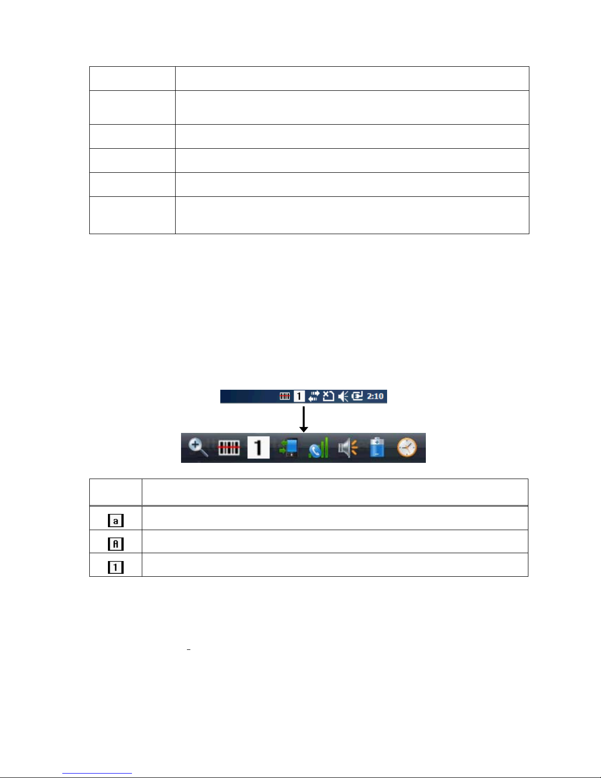
The command bar on the screen displays an icon that indicates the alpha/numeric status of the
keypad.
Icon Keypad Status
Lowercase alpha mode.
Uppercase alpha mode.
Numeric mode.
5.5. White Indicators on the Numeric Keys
(Please refer to Pointmobile Keyboard Specification v1.5 document)
The mode is changed as Numeric / Upper / Lower when you press the white key, you can type each
number/ capital letter/small letter in the sequence
Each number key display the characters typed when you press that key in alpha mode.
Note that when typing in alpha mode, you must use the same multi-press method you would use
when typing letters on a phone keypad. Each key press types the next letter in the sequence as
Page 37
36
displayed by the alpha indicator.
5.6. BLUE Key Combinations
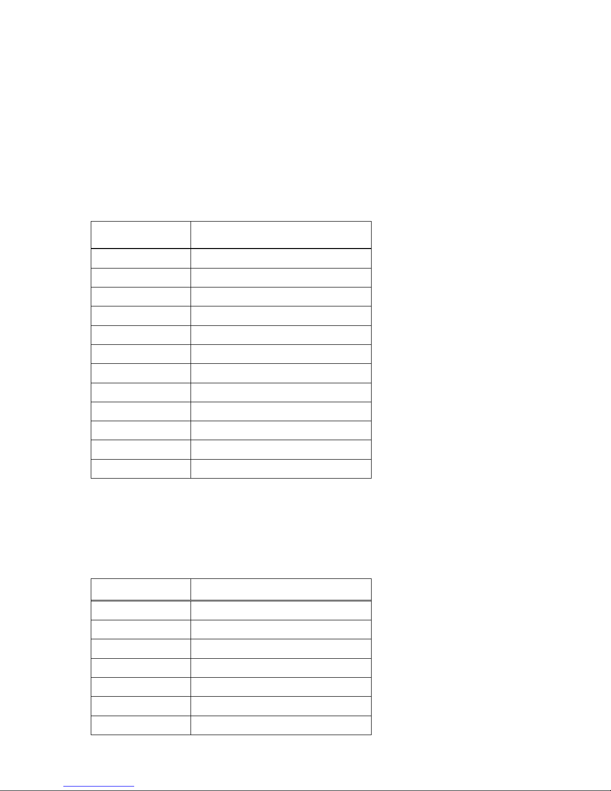
Buttons can be programmed to execute different functions using the Program Button program in the
Control Panel. The following buttons on the HANDY TERMINAL are programmed for the listed
function.
BLUE key modifies the next key pressed to perform specific functions.
Key Combination Function
BLUE + 1 F1
BLUE + 2 F2
BLUE + 3 F3
BLUE + 4 F4
BLUE + 5 F5
BLUE + 6 F6
BLUE + 7 F7
BLUE + 8 F8
BLUE + 9 F9
BLUE + 0 F10
BLUE + SP Align the screen (Press ESC to exit)
BLUE + . Windows Menu
5.7.
Program Buttons
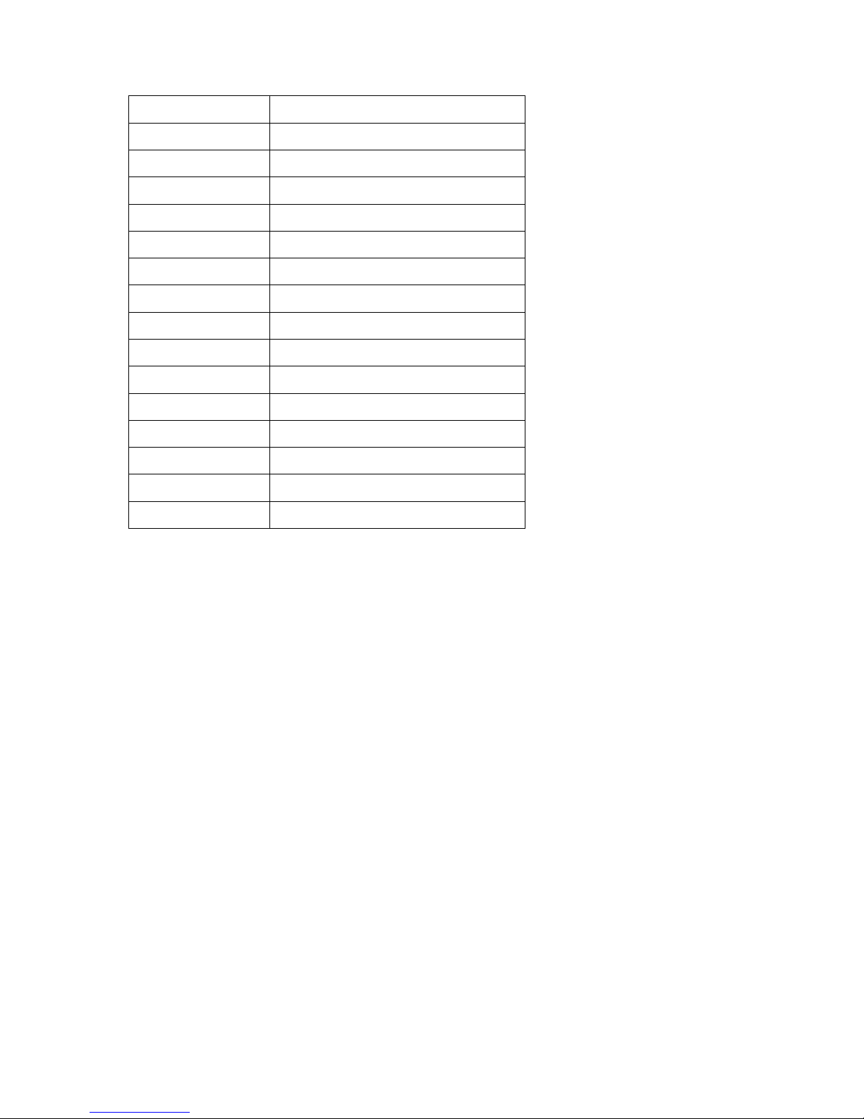
Buttons can be programmed to execute different functions using the Program Button program in the
Control Panel. The following buttons on the HANDY TERMINAL are programmed for the listed
function.
Key Combination Function
FSCAN Do Scan
LSCAN Do Scan
RSCAN Do Scan
VOL+ Volume up
VOL- Volume down
ESC Esc Key
TAB Tab Key
Page 38
37
BACK SPACE Bksp Key
ENTER Return Key
DEL Del Key
OK OK
STARTMENU Start Menu Key
CALIBRATION Touch Calibration
F1 No Action
F2 No Action
F3 No Action
F4 No Action
F5 No Action
F6 No Action
F7 No Action
F8 No Action
F9 No Action
F10 No Action
6. Using the Image Engine
6.1. Overview
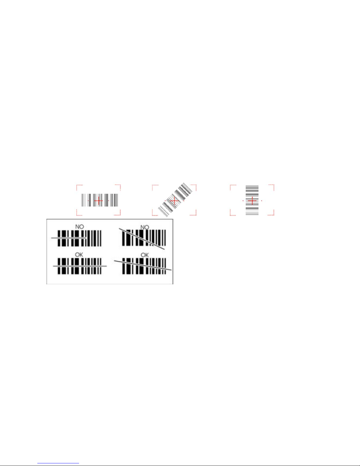
The HANDY TERMINAL contains an N560X 2D image engine that instantly reads all popular 1D and
2D bar codes and supports omni-directional aiming and decoding or a N4313 1D laser engine that
reads all popular 1D bar codes. The image engine can also capture digital images, such as
signatures and pictures.
☞NOTE:
It may not read the barcode due to specular reflection if scanning from directly above. Try again after
changing angle.
☞NOTE:
It may not read the barcode, if this handy terminal is too close to or too far from the barcode even if the
barcode is within the aiming range. Move the handy terminal toward or away from the barcode slowly and try again. The
aiming range is for reference only.
☞NOTE:
It may not read the barcode if the barcode surface is curved. Scan the barcode at the center of the aiming
range.
☞NOTE:
It may not read the barcode if the barcode surface is dirty. Try again after cleaning the barcode.
☞NOTE:
It may not read the barcode if the image engine window is dirty. Try again after wiping the window with a
cotton swab or similar soft object gently.
Page 39
38
☞
NOTE:
It may not read the barcode according to the direct sunlight or the brightness of the surrounding. Try again
away from the direct sunlight. Try again after adjusting the brightness of the surrounding if indoors.
☞
NOTE: It may not read the barcode if it is blue on white background. Try again after changing angle or
adjusting the brightness of the surrounding.
☞
NOTE: It may not read the barcode if it is black on silver background. Try again after changing angle or
adjusting the brightness of the surrounding.
☞
NOTE: Bar codes printed on glossy or laminated paper are best read at angles greater than 5° in relation
to the Laser Engine. This prevents bright illumination reflections from being returned to the Laser Engine..
☞
NOTE: Performance may be impacted by bar code quality and environmental conditions
☞
NOTE: Misreading may occur, if the bar code isn’t positioned correctly. Recommended scanner beam
positions are as follows
6.2.
Available Image Engines
The HANDY TERMINAL is equipped with an N560X.
6.3.
Depth of Field
Depth of Field for N560X
Page 40
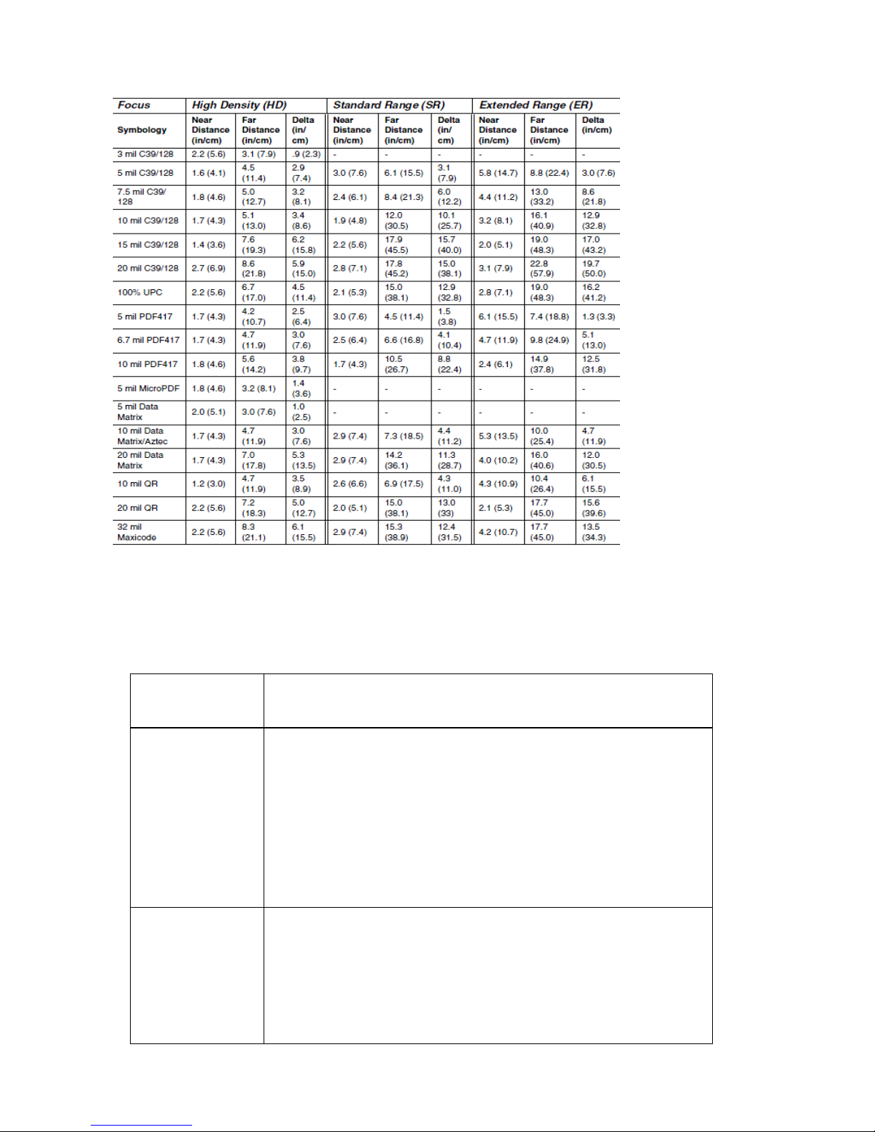
39
☞NOTE: Test Condition: Room Temperature (Approx. 23°C), 0 Lux.
New picture : N5600-IM Rev E.pdf base.
6.4. Supported Bar Code Symbologies
Symbology Type Symbology Name
1D Symbologies
Codabar
Code 11
Code 128
Code 39
Code 93 / 93i
EAN-8
EAN-13
Interleaved 2 of 5
Reduced Space Symbology
UPC-A
UPC-E
MSI
Trioptic Code
Code 32 Pharmaceutical (PARAF)
Matrix 2 of 5
Telepen
GS1-128
ISBT 128
Straight 2 of 5 (Industrial)
UPC-A (Coupon Code)
UPC-E1
Straight 2 of 5 (IATA)
2D Symbologies
Aztec Code
Data Matrix
MaxiCode
MicroPDF417
PDF417
QR Code and Micro QR Code
Han Xin
Page 41

40
Composite Codes
EAN.UCC Composite
Codablock F
TCIF Linked Code 39 (TLC39)
OCR
OCR
Postal Codes
Postnet
British Post(BPO)
Canadian Post
Australian Post
Japanese Post
Planet Code
KIX (Netherlands) Post
China Post
Korea Post
4-CB(4-State Customer Barcode)
ID-Tag(UPU 4-State)
6.5. Activating the Engine
When a scanning application is open, press the Scan key to activate the image engine.
6.6. Using Demos
Handy Terminal Demos are software utilities loaded on all Handy Terminal terminals that
demonstrate the advanced features of the terminal. There are two Demos that feature the image
engine: Image Demo and Scan Demo.
To access these demos, tap Start -> Demos.
• Select Scan Demo to verify decoding, or
• Select Image Demo to verify imaging (not available on device using the N4313 laser engine).
6.7. Decoding
The Handy Terminal supports Full-area Imaging decode mode.
Full-area Imaging
With full-area imaging the Handy Terminal supports omni-directional aiming meaning that a
positive read can be obtained from many positions. For details, see Omni-Directional
Scanning Positions on paragraph 6.10.
6.8. To Decode a Bar Code
1. Tap Start -> Demos -> Scan Demo.
2. Position the Handy Terminal over one of the Sample Bar Codes on paragraph 6.9.
A range of 4–10 inches (10–25 cm) from the bar code is recommended.
3. Project the aiming brackets by pressing and holding the Scan key. The Scan LED lights red.
4. Center the aimer crosshair over the bar code. The aiming beam should be oriented in line with
the bar code to achieve optimal decoding; Omni-Directional Scanning Positions on paragraph
Page 42
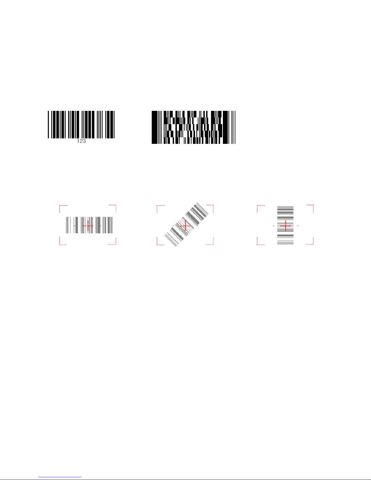
41
6.10.
5. When the bar code is successfully decoded, the decode LED lights green and the terminal beeps.
6.9.
Sample Bar Codes
You can use the following bar codes to verify decoding:
Code 39 PDF 417
6.10.
Omni-Directional Scanning Positions
The high-vis aiming pattern frames the bar code to provide you with the best scanning
performance.
☞
NOTE:
To achieve the best read, the aiming beam should be centered horizontally across the bar code.
The aiming pattern is smaller when the terminal is held closer to the code and larger when the
terminal is held farther from the code. Symbologies with smaller bars or elements (mil size) should
be read closer to the unit whereas larger bars or elements (mil size) should be read farther from the
unit.
6.11.
Capturing Images
The image-capture process is an intuitive, split-second operation for experienced users. By following
basic guidelines, however, new users can easily develop their own technique and, with practice,
quickly learn to adapt to different application environments.
Image Preview
When the imaging process is initiated, the touch screen displays a preview of the object.
This is a live video image of what the imager is currently viewing and has a slightly
degraded appearance compared to the captured image. This is normal; the captured image
has a higher resolution.
File Formats
The Handy Terminal supports BMP file format only.
Page 43
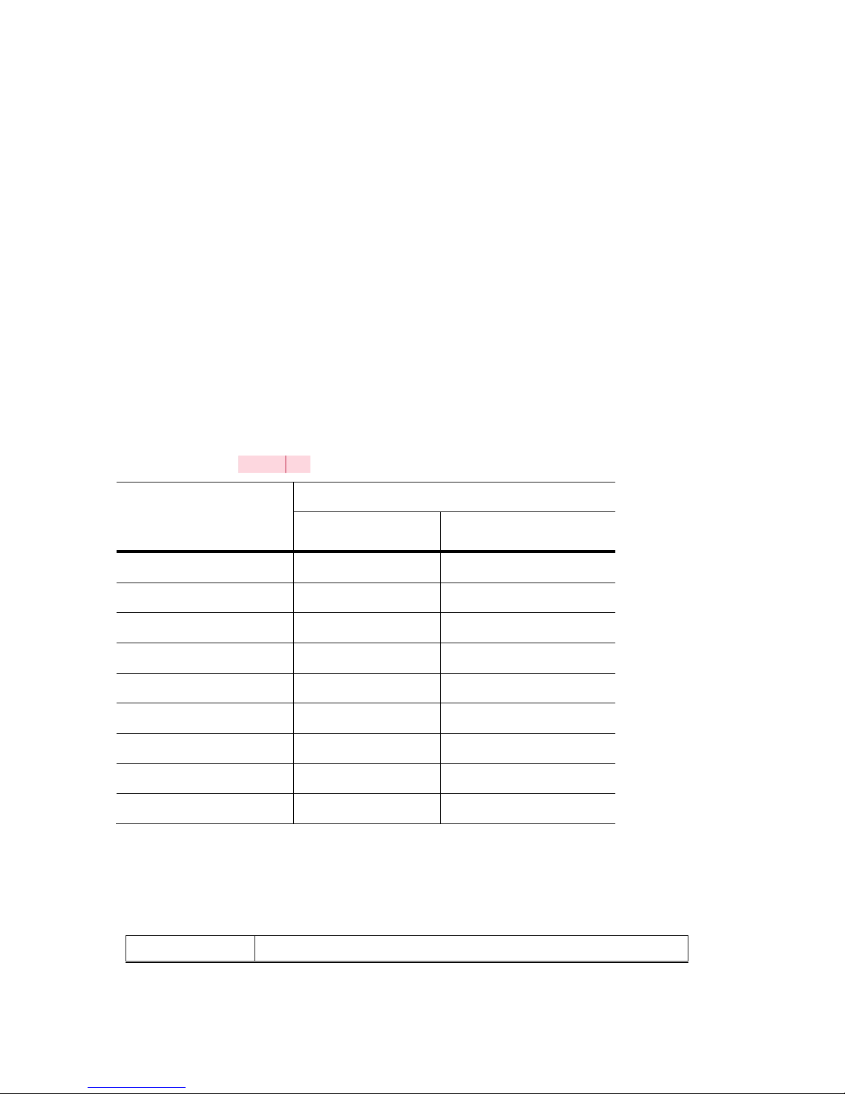
42
7. Using the Laser Engine
7.1. Overview
The HANDY TERMINAL (N4313 laser version) contains a laser diode that emits a beam toward an
oscillating mirror that scans through the code and the reflected light is bounced off of two mirrors
back to the collector. The laser version reads all popular 1D bar codes. See Overview on paragraph
6.1 also.
☞NOTE: Performance may be impacted by bar code quality and environmental conditions.
7.2. Available Laser Engines
The HANDY TERMINAL can be equipped with an N4313 laser engine (depending on the
configuration purchased).
7.3. Depth of Field
Depth of Field for N4313[W1]
Code Size
Reference Range
Near Distance
(in/cm)
Far Distance
(in/cm)
Code 39 4 mil 5in / 12.7cm 5.4in / 13.8cm
Code 39 5 mil 4.1in / 11.7cm 7.2in / 18.4cm
Code 39 7.5 mil 4.1in / 10.4cm 10.7in / 27.4cm
Cede 39 10 mil 3.4in / 8.7cm 14.5in / 36.9cm
UPC 13 mil, 100% 1.9in / 4.7cm 16.8in / 42.8cm
Code 39 15 mil 1.9in / 4.7cm 19.9in / 50.4cm
Code 39 20 mil (*) 25.5in / 64.6cm
Code 39 40 mil (*) 26.7in / 67.5cm
Code 39 55 mil (*) 31.8in / 80.8cm
☞NOTE: Test Condition: Room Temperature(Approx. 20°C), 450 ~ 500 Lux.
☞NOTE: * = dependent on width of bar code.
7.4. Supported Bar Code Symbologies
Symbology Type Symbology Name
Page 44
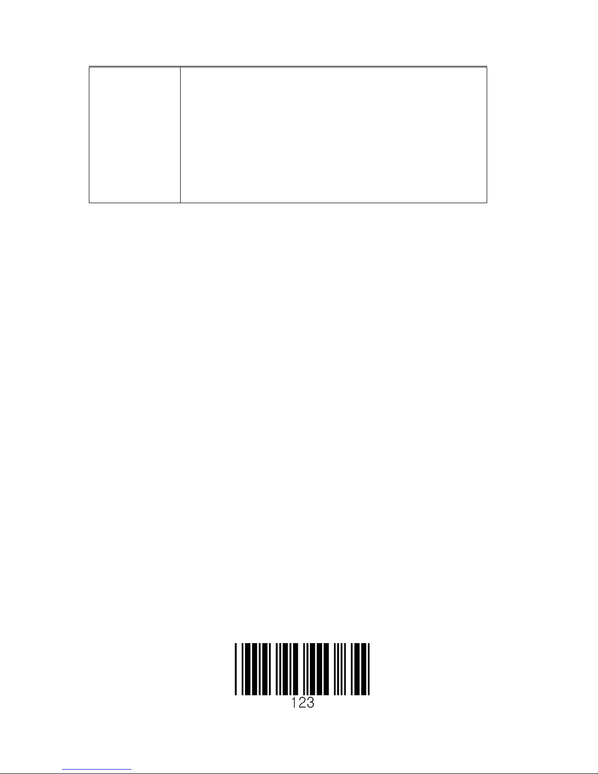
43
1D Symbologies
Codabar
Code 39
Interleaved 2of 5
Nec 2of5
Code 93
Straight 2of5 Industrial
Straight 2 of 5 IATA
Matrix 2 of 5
Code 11
Code 128
GS1 128
Telepen
UPC A
UPC E
EAN 13
EAN 8
MSI
Plessey
GS1 Databar Omnidirectional
GS1 Databar Limited)
GS1 Databar (Expanded
China Post
Trioptic
7.5. Activating the Engine
When a scanning application is open, press the Scan key to activate the laser engine.
7.6. Using Demos
Handy Terminal Demos are software utilities loaded on Handy Terminals that demonstrate the
advanced features of the terminal.
To access these demos, tap Start > Demos.
• Select Scan Demo to verify decoding
7.7. Decoding a Bar Code
1. Tap Start > Demos > Scan Demo.
2. Position the Handy Terminal over one of the Sample Bar Codes on paragraph 7.8.
A range of 4-10 inches (10-25 cm) from the bar code is recommended.
3. Project the aiming beam by pressing and holding the Scan key. The Scan LED lights red
.
4. Center the aimer beam horizontally over the bar code and highlight all of the vertical bars of the
bar code. The aiming pattern is smaller when the terminal is held closer to the code and larger
when the terminal is held farther from the code. Symbologies with smaller bars or elements (mil
size) should be read closer to the unit whereas larger bars or elements (mil size) should be read
farther from the unit.
5. When the bar code is successfully decoded, the decode LED lights green and the terminal beeps.
7.8. Sample Bar Code
You can use the following bar code to verify decoding:
Page 45
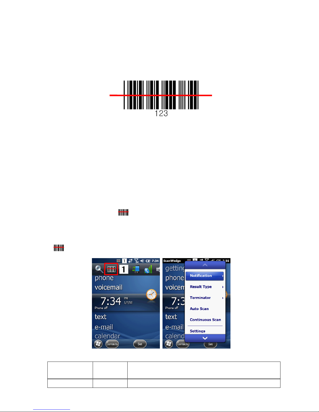
44
7.9. Scanning Positions
The aiming beam must be aimed across the entire bar code to provide you with the best scanning
performance. The aiming pattern is smaller when the terminal is held closer to the code and larger
when the terminal is held farther from the code. Symbologies with smaller bars or elements (mil
size) should be read closer to the unit whereas larger bars or elements (mil size) should be read
farther from the unit.
8. Using ScanWedge
8.1. Overview
ScanWedge sends data from the installed scan engine(N4313 or N560X) to the foreground
application as keystrokes or clipboard. The foreground application is the open software application
whose window is currently active on the display.
As a result, you can check decoded bar code data with Microsoft WordPad.
8.2. Enabling ScanWedge
ScanWedge is enabled by default in Handy Terminal
Tap the ScanWedge icon once . ScanWedge initializes and enables.
Command Bar Menu
Tap icon in taskbar to open the command bar menu.
Menu Item Sub Item This item …
Notification Beep Enables and disables the audio notification for decode/data
Page 46
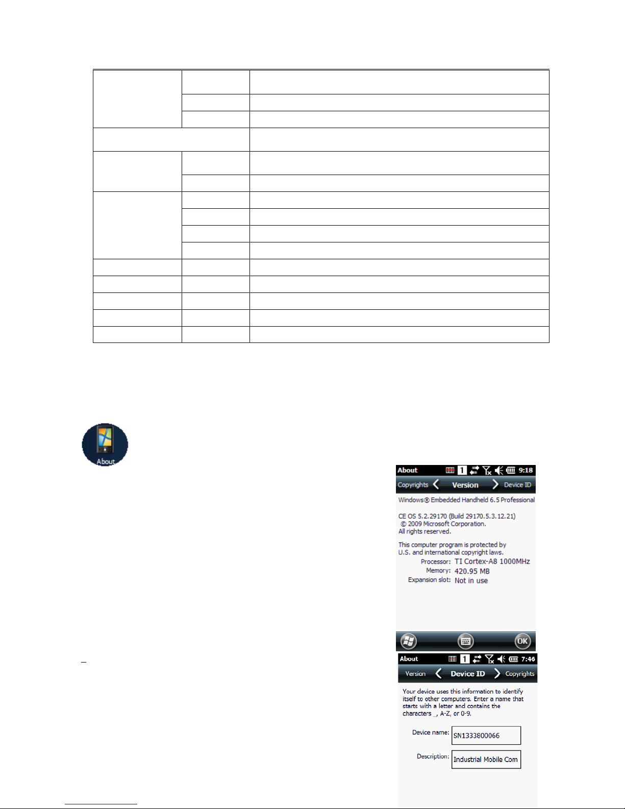
45
reception. There is one sound for success and another sound for an
error.
LED Enables and disables LED notification for decode/data reception.
Vibrator Enables and disables Vibrator notification for decode/data reception.
Specifies the method to use when sending the decoded message to
the foreground application
Result Type
Keyboard
Event
Send decoded bar code data as Keyboard event(stroke)
Clipboard Send decoded bar code data to clipboard(copy & paste)
Terminator
None Add nothing at end of decoded bar code data
CRLF Add CRLF at end of decoded bar code data
Space Add Space at end of decoded bar code data
Tab Add Tab at end of decoded bar code data
Auto Scan - Enable Auto Scan feature
Continuous Scan - Enable Continuous Scan feature
Setting - Open Scanner setting applet
Disable Scanner - Disable Scanner trigger
Close - Close Scan wedge
9. Using Control Panel
9.1. System Properties
Refer to the System control panel for information related to the system.
9.1.1. Version
1. Select
2. Start > Settings > System > About > Version tab to
determine the following information about your PDA:
Operating system
Processor
Memory
Expansion slot
9.1.2. Device ID
Your device uses this information to identify itself to
other computers.
Page 47
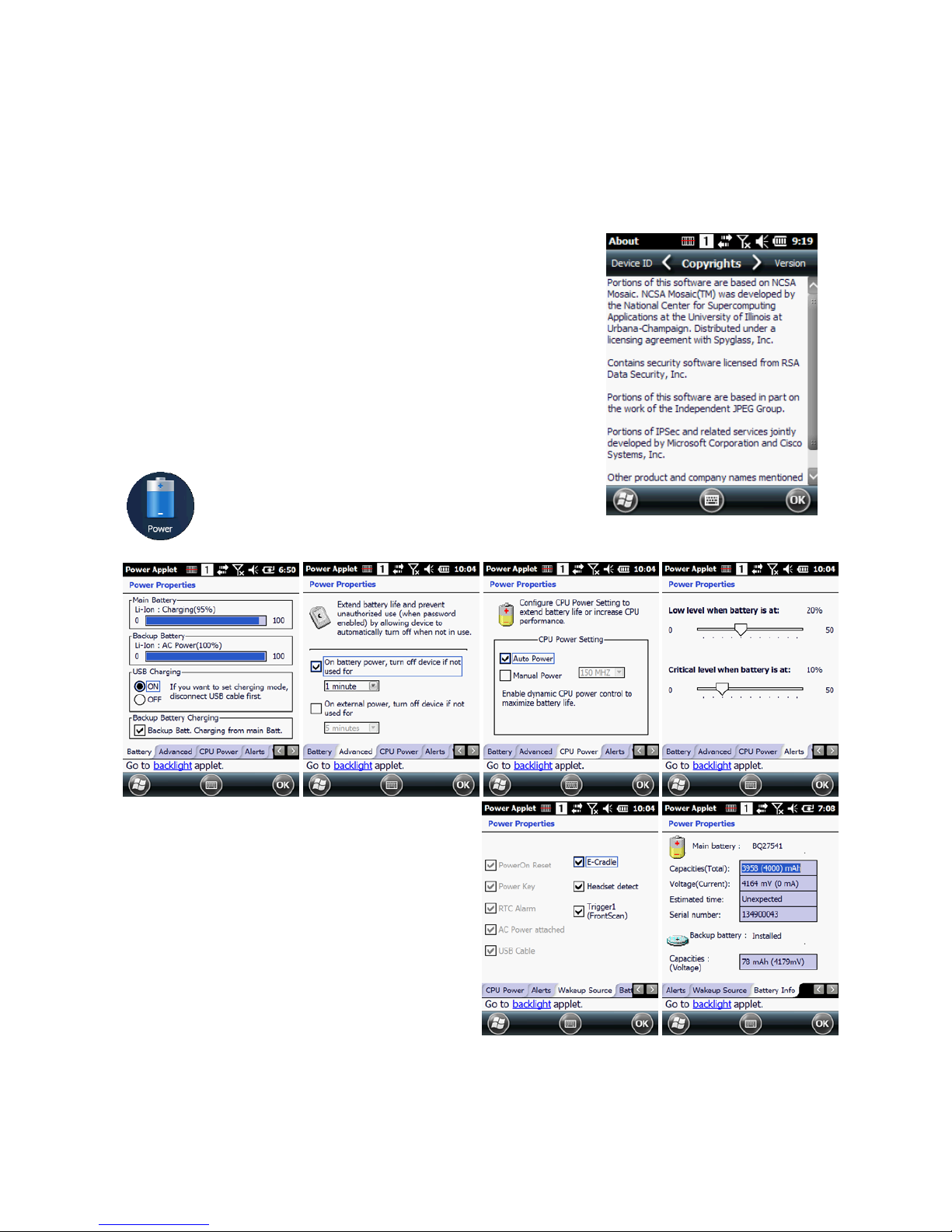
46
Terminal Serial Number will be in Device Name section by
default. You can modify it
9.1.3. Copyrights
Portions of this software are based on NCSA Mosaic.
9.2. Power properties
9.2.1. Battery tab
To see main battery level indicators open
Start > Settings > System > Power icon .
Set up the USB charging and On / Off
9.2.2. Advanced tab
To adjust power management settings,
1. Set idle time when on battery power before device suspends.
2. Set idle time when on external power before device suspends.
Page 48
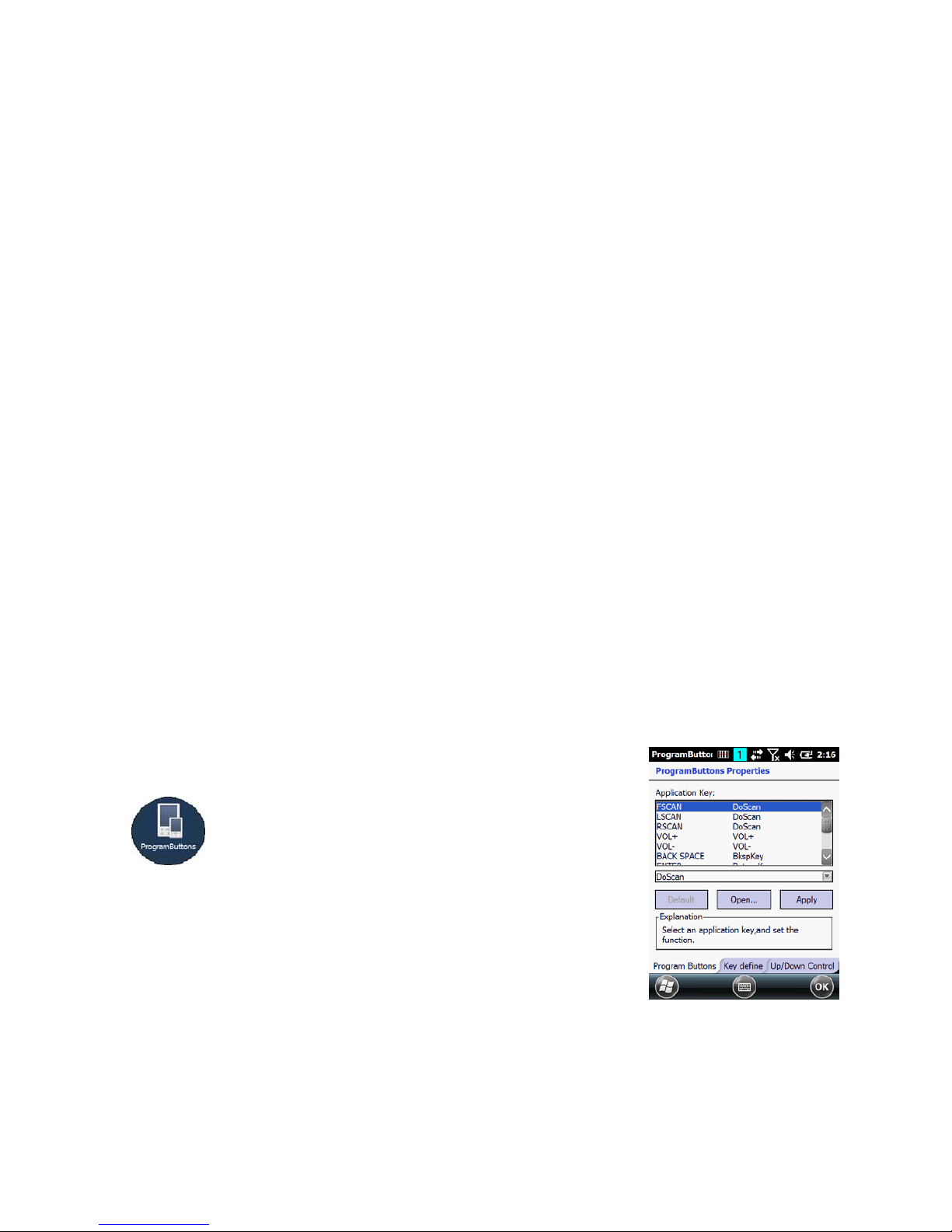
47
3. To exit, press OK from the command bar, or press the < ENT > key on the keypad.
☞NOTE:
To save battery life it is recommended to set idle time as short as possible.
9.2.3. CPU Power Tab
To adjust CPU power settings,
1. Auto Power : Enable automatically CPU power control to maximize battery life.
2. Manual Power : CPU Clock can be fixed by User.
9.2.4. Alerts Tab
Adjust the level of main battery for Low battery message and Critical battery message.
By default, 20% is set for Low battery message and 10% is set for Critical battery message.
9.2.5. Wakeup Source Tab
Enable Wake(Resume) resources from suspend(Sleep) mode
By default, all available resources are enabled
.
9.2.6. Battery Info Tab
To see battery information,
Start > Settings > System > Power icon> Battery Info Tab
Indicate Capacities, Voltage, Estimated time, Serial number etc.
9.3.
Program Button properties
9.3.1. Program Buttons Tab
1. Select
Start > Settings > Control Panel > Program buttons
2. Chose its type:
Default – button will be assigned default function.
No function – button does not have any functions.
Page 49
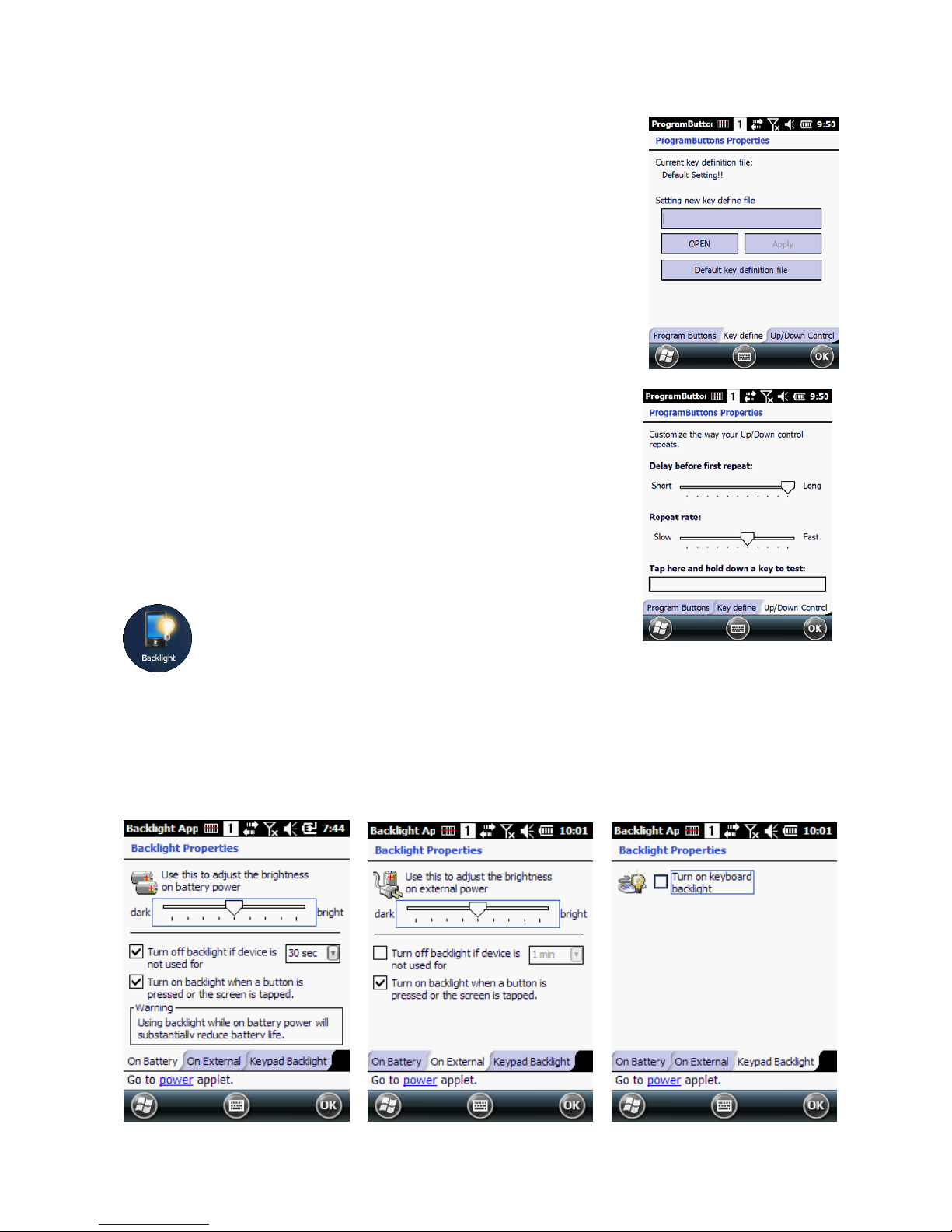
48
Scan key – button is used as Scan key.
Application – click on Open button and select
application to bind with this key.
4. To exit, press OK from the command bar, or press the
< ENT > key on the keypad
9.3.2. Key define Tab
Apply and Set the key which is already defined
9.3.3. Up/Down Control Tab
Customize the way the Up/Down control repeats
• Delay before first repeat (Short/Long)
• Repeat rate (Slow/Fast)
☞NOTE:
It is useful for a customer to want to remap keyboard.
9.4. Backlight Properties
Modify display and keyboard backlight brightness.
Also set backlight options (i.e. turn off time).
To modify backlight settings open:
Start > Settings > Control Panel > Backlight
Page 50

49
9.4.1. Battery power Tab
Modify display backlight settings when device runs on batteries.
Set display brightness level
Set backlight timeout time.
Available options:
10 sec
30 sec
(by default)
1 min
2 min
3 min
4 min
5 min
Enable to turn on backlight when a button is pressed or the screen is tapped
☞NOTE:
To extend battery life it is recommended to set display backlight turn off time as short as possible.
☞NOTE:
To extend battery life it is recommended to set display backlight brightness level as low as possible.
9.4.2. External power Tab
Modify display backlight settings when device runs on external power.
Set display brightness level
Set backlight timeout time.
Available options:
Unchecked
(By default)
1 min
2 min
5 min
10 min
15 min
30 min
Enable to turn on backlight when a button is pressed or the screen is tapped
9.4.3. Keyboard backlight Tab
Enable Keyboard backlight when button is pressed
By default this is turned off.
9.5. Scanner Settings
To change the Scanner configuration parameter as follows:
Page 51
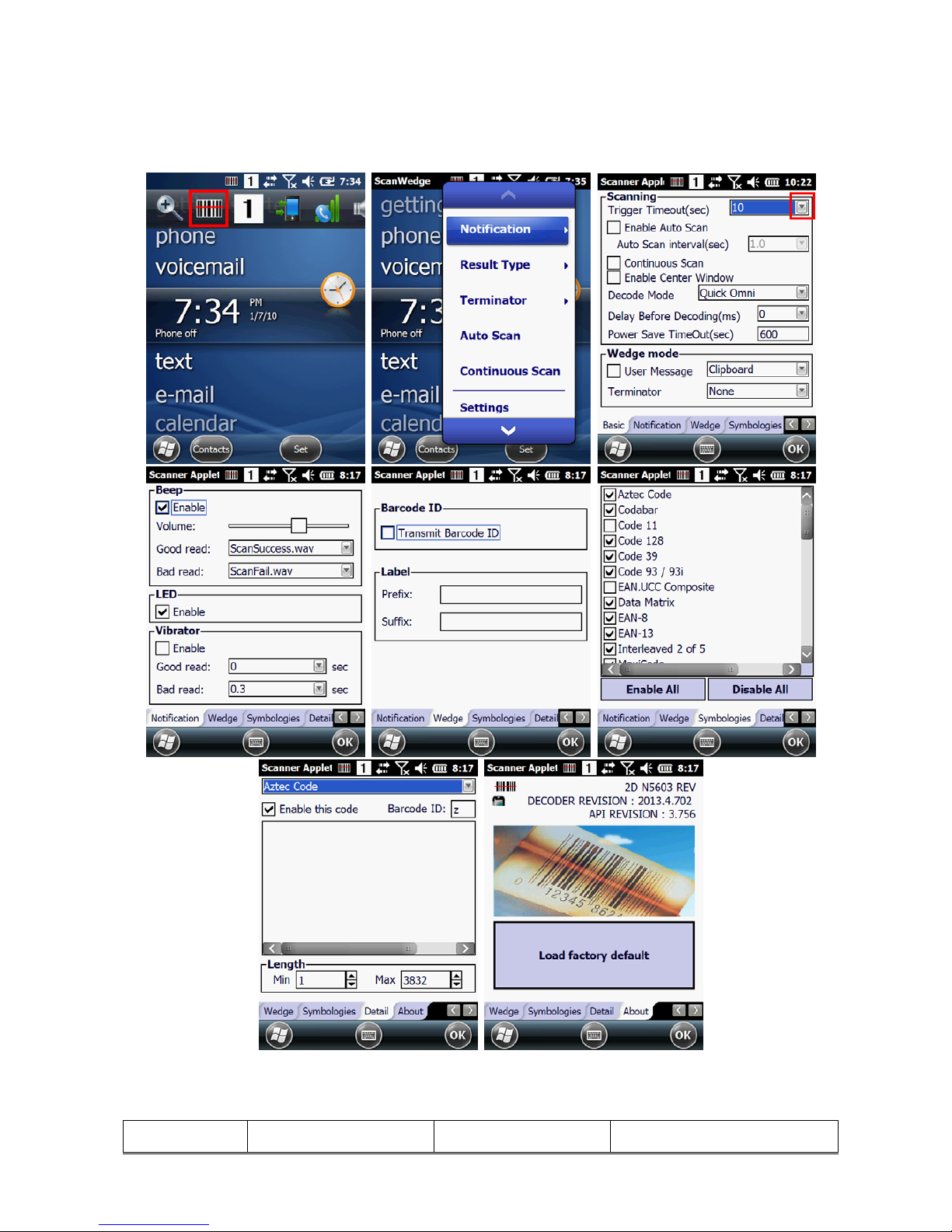
50
Tap the Scanwedge icon in the System Tray to open the menu shown in image on the right and select
Settings to open the Scanner Settings applet or Start > Settings > System > Scanner Settings
9.5.1. Scanner Settings Applet
Tab Section Option Description
Page 52
51
Basic
Scanning
Trigger timeout (sec)
Specifies the trigger time out in
seconds. If a barcode is not
decoded within the specified
timeout, the default Notifier
indicates that decoding is failed
Enable Auto Scan
Enable Auto Scan with specified
interval.
Auto Scan interval (sec) Set Auto Scan interval time.
Continuous Scan
Enable Continuous Scan without
any interval.
Enable Center Window
(IT5300SR device only)
Enable Center window. Bar
codes are decoded only if they
are within the specified windows
Decode Mode(IT5300SR
device only)
Standard:
Quick Omni
(By default)
:
Delay Before
Decoding(IT5300SR
device only)
Start to decoding after specified
milliseconds
Values: 0(default), 100, 200,
300, 400, 500, 600,
700, 800, 900, 1000
Wedge mode
User Message
Select Result Type
User Message
Keyboard Event
Clipboard(default)
Terminator
Select the desired barcode end
method from the pull down list.
Values: None, CRLF, Space,
Tab
Power Save Options
(N4313 device only)
Power Save Mode
Select Power Save Mode
OFF
SLEEP
HIBERNATE(default)
Power Save TimeOut
(sec)
1~65535
Notification
Beep
If enabled
– plays audio sound
Volume Set sounds volume.
Good read Set sound to indicate good read.
Bad read Set sound to indicate bad read.
LED
Enable Enable visual scan indicators.
Vibrator
If enabled
- Turn on LED for good/bad
scan indicator
Good read
Set vibration time after
good read.
Bad read
Set vibration time after
bad read.
Wedge
Barcode ID
Transmit Barcode ID
Enable to transmit predefined
barcode ID in Detail tab
Label
Prefix
Enter Prefix to be sent prior to
the decoded/received data.
Page 53

52
Suffix
Enter Suffix to be sent after the
decoded/received data
Symbologies
Select barcode types you want to read
There is “Enable All” and “Disable All” to enable/disable all symbologies
Tab Section Option Description
Details
Specifies or enable
available detail settings
in symbologies
Enable this code
Tap/enable this checkbox to
enable the selected bar code
type.
Barcode ID
Enter the desired features you
wish to transmit as bar code ID
Length
Set the minimum and maximum
lengths from the pull-down lists.
If the numbers are the same,
acceptable bar codes will only
be that length. Not all types will
have this option enabled.
Redundancy(N4313
device only)
If you are encountering errors
when reading some bar codes,
you may want to adjust the
redundancy count. Redundancy
adjusts the number of times a
bar code is decoded before
transmission, which may reduce
the number of errors. Note that
the higher the redundancy
count, the longer it will take to
decode the bar code
About
Specifies Barcode engine type, Firmware revision, Decider revision, API revision
Load Factory Default
After modifying the current
settings, if you wish to return to
the factory defaults, tap the
Load Factory Default button.
10. Communication
10.1.
Communication Options
Handy Terminal offers several communication options including Microsoft ActiveSync and wireless
radios.
USB Connector
The MicroUSB connector on bottom side supports USB 2.0 High speed
HandyLink Connector (Wired Communication)
The mechanical connector on the bottom panel connects the terminal to various Handy
Page 54
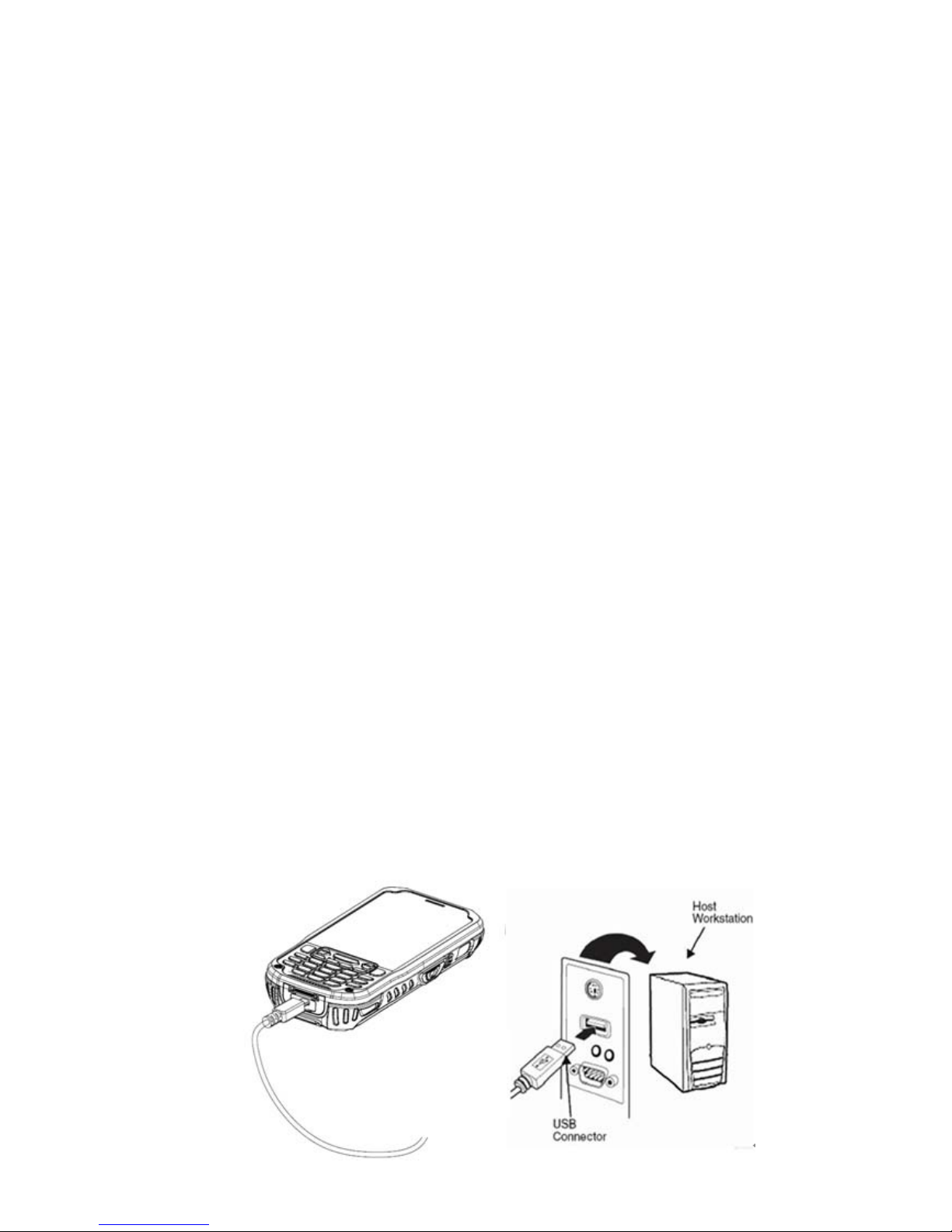
53
Terminal communication peripherals that connect to a host workstation via USB (1.1 or
higher), thus enabling ActiveSync communication.
For more information, see ActiveSync Communication on paragraph 10.4.
Wireless Radios (Wireless Communication)
HANDY TERMINALs can be equipped with an 802.11b/g/n Bluetooth radio and WWAN.
For more informatio n, see Wireless Radios on paragraph 10.14.
10.2.
Installing Additional Software
Handy Terminal is shipped with the operating system, radio drivers, and custom software (CICO)
already installed. These are the default programs that install when your terminal first boots up. You
can install additional software programs on the terminal provided that the following parameters are
met:
• The software program was created for a Windows CE device.
• The terminal has enough memory to store and run the program.
• The program has an EXE, CAB, or DLL extension.
When selecting programs, verify that the program and version of the program are designed for the
Windows Embedded Pointmobile 6.5 Pro and the terminal’s processor. You can verify your processor
by tapping Start -> Settings -> System -> About -> Version tab. Make a note of the
information in the Processor field.
To install additional software, you can use the communication options described in this chapter.
• Adding Programs via ActiveSync (paragraph 10.13).
• Adding Programs from the Internet (paragraph 10.17).
10.3.
Connecting the USB ActiveSync Cable
To facilitate USB communication between the Handy Terminal and the host workstation, you may
connect your unit to a host by using either the USB ActiveSync cable, the optional Single Slot
Docking Cradle or the optional Single Slot Ethernet Cradle. If you use the Communication Cable,
slide the cable unit onto the bottom of the terminal lining up the terminal’s micro-USB connector
with the cable unit’s connector.
Page 55

54
10.4.
ActiveSync Communication
To synchronize, ActiveSync 4.1 or higher must be installed and configured for the appropriate
communication type on the host workstation and the Handy Terminal. Handy Terminals ship with
ActiveSync already installed. Therefore, if ActiveSync is already installed on the host workstation,
you just need to connect the Handy Terminal to the host workstation (via Handy Terminal
peripheral) to initiate communication.
☞
NOTE:
You can download the most current version of ActiveSync (for Windows XP) or Windows Mobile Device
Center (Windows Vista, 7) from www.microsoft.com.
WARNING:
When communicating via ActiveSync, your terminal is designed to be connected to the host
workstation with a Pointmobile communication peripheral. We recommend use of Pointmobile peripherals, power
cables, and power adapters. Use of any non-Pointmobile peripherals, cables, or power adapters may cause damage
not covered by the warranty.
AVERTISSEMENT : Lors de la communication via ActiveSync, votre terminal est conçu pour être connecté à une
station de travail hôte avec un périphérique de communication Pointmobile. Nous recommandons l'utilisation des
périphériques, câbles d'alimentation et les adaptateurs électriques fournis par Pointmobile. L'utilisation de tout autre
périphérique peut causer des dommages non couverts par la garantie.
10.5.
Communication Type
The HANDY TERMINAL supports the following type of communication via ActiveSync through its I/O
connector on the bottom panel:
USB The USB cable and hardware peripherals allow the Handy Terminal to communicate with a
workstation through a USB port or to a network through a USB hub. The Handy Terminal supports
high -speed USB communication (USB 2.0); maximum data transfer rate is 480 Mbps. The Handy
Terminal defaults to USB communication out of the box.
10.6.
Hardware Requirements for Setup
• AC Adaptor (if needed)
• USB ActiveSync Cable (for USB communication)
• ActiveSync v4.1 or higher (for Windows XP), Windows Mobile Device Center (for Vista and
Windows 7) installed on the host workstation
• Windows XP, Windows Vista, Windows 7 computer.
10.7.
Software Requirements for Communication
To sync successfully, ActiveSync must be configured for the same communication type on both the
host workstation and the Handy Terminal. ActiveSync must be setup on your workstation before you
initiate synchronization from the terminal for the first time.
10.8.
Setting Up the Host Workstation
Verify that ActiveSync is configured to use the appropriate communication type by selecting File ->
Page 56
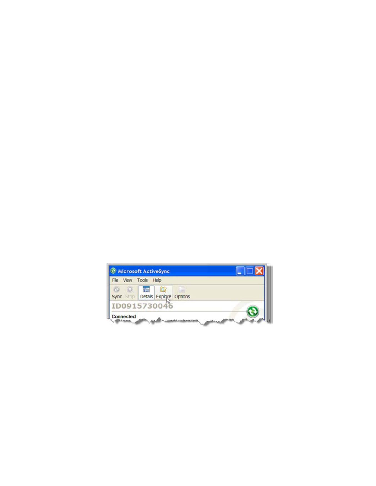
55
Connection Settings.
For USB communication, check Allow USB connections.
10.9.
Communicating with the Handy Terminal
After setting up both the workstation and the terminal, ActiveSync connection should be automatic.
1. Connect the Handy Terminal to a communication peripheral, such as the Handy Terminal Docking
cradle.
2. The Handy Terminal automatically opens ActiveSync or Windows Mobile Device Center to
establish a connection.
10.10.
Synchronizing with the Host Workstation
After setup, synchronization begins automatically whenever the terminal’s mechanical connector
connects to a Handy Terminal peripheral that is connected to a host workstation with ActiveSync
installed.
10.11.
Exploring the Terminal from the Workstation
When the terminal and desktop computer are connected, open the main ActiveSync window (on the
desktop), and click Explore.
The Mobile Device folder opens in Windows Explorer.
Page 57
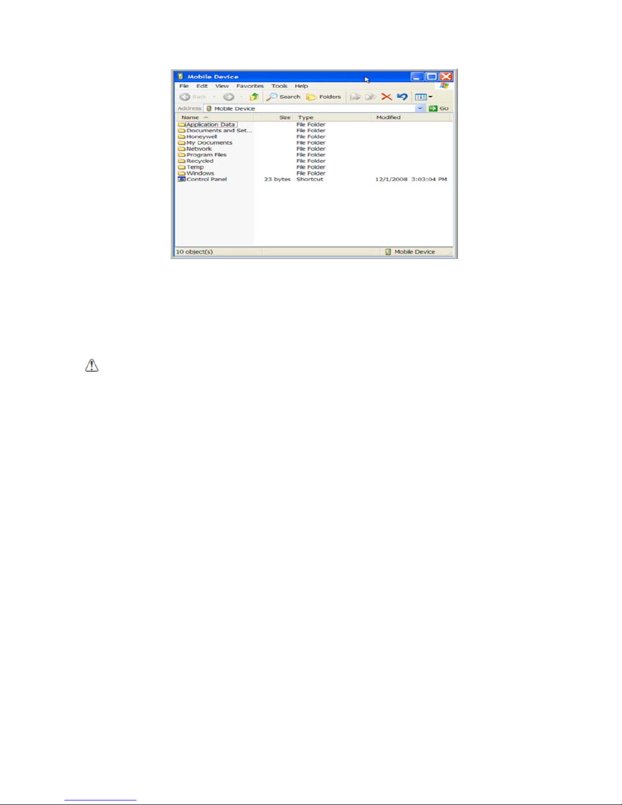
56
The Handy Terminal is now treated as a mass storage device, and transferring files is as simple as
dragging and dropping or copying and pasting as you would for moving files between folders on
your hard drive.
10.12.
Adding Programs via ActiveSync
WARNING:
When selecting programs, verify that the program and version of the program are designed for the
Windows Embedded Pointmobile 6.5 Pro and the terminal’s processor. You can verify your processor
by tapping
Start -> Settings -> System -> About -> Version
tab. Make a note of the information in the Processor
field.
AVERTISSEMENT : Lors de la sélection de programmes, vérifiez que ceux-ci et leur version ont bien été conçus
pour Windows Embedded Pointmobile 6.5 Pro et sont supporté par le processeur du terminal. Vous pouvez vérifier
le type de votre processeur en appuyant sur Démarrer -> Paramètres -> Système -> A propos -> Version.
Generally, software for Windows Embedded Pointmobile 6.5 Pro devices must be installed to the
host workstation first, then transferred to the Handy Terminal.
1. Download the program to the workstation from either the Internet or the install CD. You may see
a single *.exe or setup.exe file, a *.cab file, or *.dll. (There may also be several versions of files
for different device types and processors.)
2. Read any installation instructions, Read Me files, or documentation that comes with the program.
Many programs provide special installation instructions.
3. Connect the terminal to the workstation via a Handy Terminal communication peripheral.
If the File is an Installer
An installer program is one that installs to the workstation and the terminal simultaneously; one
process installs to both devices.
1. On the workstation, the *.exe or *.setup.exe file. The installation wizard begins.
2. Follow the directions on the workstation screen.
The installation process includes transferring the software to the terminal via ActiveSync.
Page 58

57
If the File is Not an Installer
Some programs cannot be installed on workstations because they are designed exclusively for
Windows Embedded Pointmobile 6.5 Pro devices. In these cases, the appropriate files must be
stored on the host workstation and transferred to the terminal via ActiveSync Explore.
☞NOTE:
If an error message stating that the program is valid but designed for a different type of computer appears
when you try to install the program on the workstation, the program is not an installer.
1. If you cannot find any installation instructions for the program in the Read Me file or
documentation, open ActiveSync or Windows Mobile Device Center on the workstation and
click Explore.
2. On the workstation, navigate to the workstation folder containing the program file(s) and copy
them to the Program Files folder on the terminal.
If you want the program to persist through hard resets, save the program to the
Autoinstall
\ Cabfile folder(\AutoInstall\Cabfile).
3. On the terminal Desktop, File Explorer in Windows Menu navigate to the folder where the
program is located.
4. Tap on the program file to install it.
If you copied the file to the Autoinstall
\Cabfile folder, you can choose to install the program by
performing a hard reset. The program installs as part of initialization.
5. After installation is complete, access the program by tapping Start -> Programs, and the
program appears on the Programs screen. Tap the icon to open the program.
10.13.
Wireless Radios
There are four radio options: 802.11b/g/n Bluetooth, Phone and GPS.
1. 802.11 b/g/n (WLAN configuration): Integrated Wi-Fi (802.11b/g/n Radio), up to 72.2Mbps
2. Bluetooth (WPAN configuration): Integrated Bluetooth v2.1+EDR
3. Phone (WWAN configuration): 3G WWAN HSPA+Module
4. GPS: Module inherent to HSPA+ Module
☞NOTE:
PM60 does not provide all Bluetooth profiles.
10.14.
Connecting the Terminal to a Wireless Network
You connect the terminal to a wireless network through the on-board radio (802.11b/g/n Bluetooth
and/or Phone).
Each radio has its own configuration program and requires specific information about the wireless
network to connect. Successful connection depends on your network infrastructure about which you
will need specific information from your network administrator.
☞NOTE:
802.11 b/g/n radio module is off by default, in order to avoid wasting energy, you can switch it off using the
Wireless Communications applet
Page 59

58
☞NOTE:
Suspending the terminal powers off the 802.11 b/g/n radio and drops the radio connection. When the
terminal resumes, depending on the radio power mode and security protocol selected, it may take up to 30 seconds
for the 802.11 b/g/n radio drivers to re-associate the radio to the network.
☞NOTE:
Area coverage and radio performance may vary, due to environmental conditions, access points types or
interference caused by other devices (microwave ovens, radio transmitters, etc.). If necessary, please turn off the
WALN or Bluetooth.
☞NOTE:
Radio performance may vary if using WLAN, Bluetooths and Phone and phone imultaneously. If necessary,
please turn off either WLAN or Bluetooth and/or Phone..
10.15.
WLAN (802.11 b/g/n Radio)
HANDY TERMINAL has a 2.4 GHz 802.11 b/g/n WLAN (Wireless Local Area Network) radio that
uses Direct Sequence Spread Spectrum (DSSS) technology. The radio is interoperable with other
802.11b/g/n, Wi-Fi compliant products including access points (APs), workstations via PC card
adapters, and other wireless portable devices.
By default, the 802.11b/g/n radio is powered-off (i.e., disabled) “out of the box” To power it on
(i.e., enable), press the vertical arrow (bottom right corner of screen) and select Turn Wireless
LAN On. The enable/disable state of the radio will survive subsequent soft and hard resets. The
next step is to configure the connection parameters of the radio to connect to a wireless network.
Configuring the WLAN Radio
The WLAN radio is configured in the Pointmobile WLAN Client, which you access by the program
icon in the command bar.
10.16.
Adding Programs from the Internet
When you have established a network connection (whether via Wireless LAN, Bluetooth, or
activeSync), you can access the Internet and download additional software programs.
When selecting programs, verify that the program and version of the program are designed for
Windows Embedded Pointmobile 6.5 Pro and the terminal’s processor. You can verify your
processor by tapping Start -> Settings -> Control Panel -> System -> General tab. Make a
note of the information in the Processor field.
1. Open Internet Explorer and navigate to the program’s location. You may see a single *.exe or
setup.exe file, or several versions of files for different device types and processors.
2. Select the program version that matches your Handy Terminal and processor.
3. Read any installation instructions, Read Me files, or documentation that comes with the program.
Many programs provide special installation instructions.
4. Download the program to the terminal directly from the Internet.
You would normally store the program in the
Program Files folder unless another location is
required by the program.
5. On the terminal, the installer file; e.g., the *.exe file.
6. The installation wizard for the program begins.
7. Follow the directions on the screen to complete installation.
Page 60

59
11. Bluetooth Handler
Bluetooth wireless technology is a short-range communications technology to connect portable
and/or fixed devices while maintaining high levels of security.
11.1.
Enabling the Bluetooth Radio
1. Select the device panel indicated by the UP arrow in the lower, right portion of the display.
2. Tap Turn Bluetooth On.
The Bluetooth icon appears in the task bar.
☞NOTE:
In order to avoid wasting energy, the Bluetooth, module is off by default. If you need to have Bluetooth
working, the module must be powered on using the Wireless Communications applet.
☞NOTE:
Suspending the terminal powers off the Bluetooth radio and drops the Bluetooth connection. When the
terminal resumes, it takes approximately 10 seconds for the Bluetooth radio driver to re-initialize the radio.
☞NOTE:
Area coverage and Bluetooth radio performance may vary, due to environmental conditions or interference
caused by other devices (microwave ovens, radio transmitters, etc.).
11.2.
Connecting to Other Devices
Before connecting to another device, make sure that the Bluetooth connection on the other device is
enabled.
1. Tap on the Bluetooth icon in the task bar.
The Bluetooth Handler appears on the screen.
2. Add New Device
The available services of all devices / profiles in range display in the Bluetooth Handler.
11.3.
Pairing Bluetooth Devices
Connecting Bluetooth devices usually requires that they be paired; the same passkey must be
entered for each device. If you want to connect the HANDY TERMINAL to a device without any input
method (e.g., printers, headsets), refer to the user documentation that acc ompanied the device for
pairing information.
1. Tap on the desired device / profile in the Bluetooth Handler.
2. Tap the Next Button on the bottom
Once asked if you need to authenticate the device,
3. Enter 4 random digits and tap the Next button.
4. Enter the same digits on the other device when prompted.
5. After pairing, tap on the selected device / profile and select Active.
11.4.
Setting Up a Bluetooth Printer
Page 61

60
1. Make sure that the Bluetooth printer is on and activated.
2. If not done so already, turn Bluetooth On (by selecting the vertical arrow on the Command Bar).
3. Tap Scan Device, which runs a Bluetooth Inquiry, then SDP Query.
4. If you see your Bluetooth printer device displayed. You can press the Refresh button to search
again.
12. Single Slot cradle/Single Ethernet cradle Device
☞
NOTE:
The cradle is option accessory and needed to purchase separately with incidental expenses in the aftermarket
12.1.
Overview
☞
NOTE:
The information in this chapter applies to both the Single Slot cradle and Single Ethernet cradle devices
unless otherwise indicated.
As the hub of your HANDY TERMINAL system, the Single Slot cradle charging and communication
cradle supports full-speed USB 2.0 with a workstation. The Single Ethernet cradle is identical to the
Single Slot cradle except it supports Ethernet communication as well as full-speed USB 2.0
12.2.
Battery Charging
The base should complete a full charge of the battery pack in 5 hours for the standard
capacity 4000mAh: 60-BTSC pack on the handy terminal. .
In addition to charging, the base powers the terminal’s intelligent battery charging system, which
protects the battery from being damaged by overcharging. The terminal senses when a battery pack
is fully charged and automatically turns off the charger. If the battery voltage drops below the
charge threshold, the charger turns on again to maintain the battery at full capacity. As a result,
Handy Terminals may be stored in the base indefinitely without damage to the terminals, battery
packs, or peripherals. For prolonged storage, see Storage Guidelines on paragraph 4.20.
12.3.
Power Supply
The power cable that ships with each terminal also powers the base.
WARNING:
We recommend use of Pointmobile peripherals, power cables, and power adapters. Use of any
non-Pointmobile peripherals, cables, or power adapters may cause damage not covered by the warranty.
We recommend use of Pointmobile Li-Ion battery packs. Use of any non- Pointmobile battery may damage not
covered by warranty.
AVERTISSEMENT : Nous recommandons l'utilisation des périphériques, câbles d'alimentation et les adaptateurs
électriques fournis par Pointmobile. L'utilisation de tout autre périphérique, peut causer des dommages non
couverts par la garantie.
Nous recommandons l'utilisation de batteries Li-Ion approuvées par Pointmobile. L'utilisation de toute autre batterie
peut causer des dommages non couverts par la garantie
WARNING:
DO NOT attempt to charge damp/wet handy terminals or batteries. All components must be dry
before connecting to an external power source.
AVERTISSEMENT : Nous recommandons l'utilisation des périphériques, câbles d'alimentation et les adaptateurs
électriques fournis par Pointmobile. L'utilisation de tout autre périphérique, peut causer des dommages non
couverts par la garantie.
Page 62
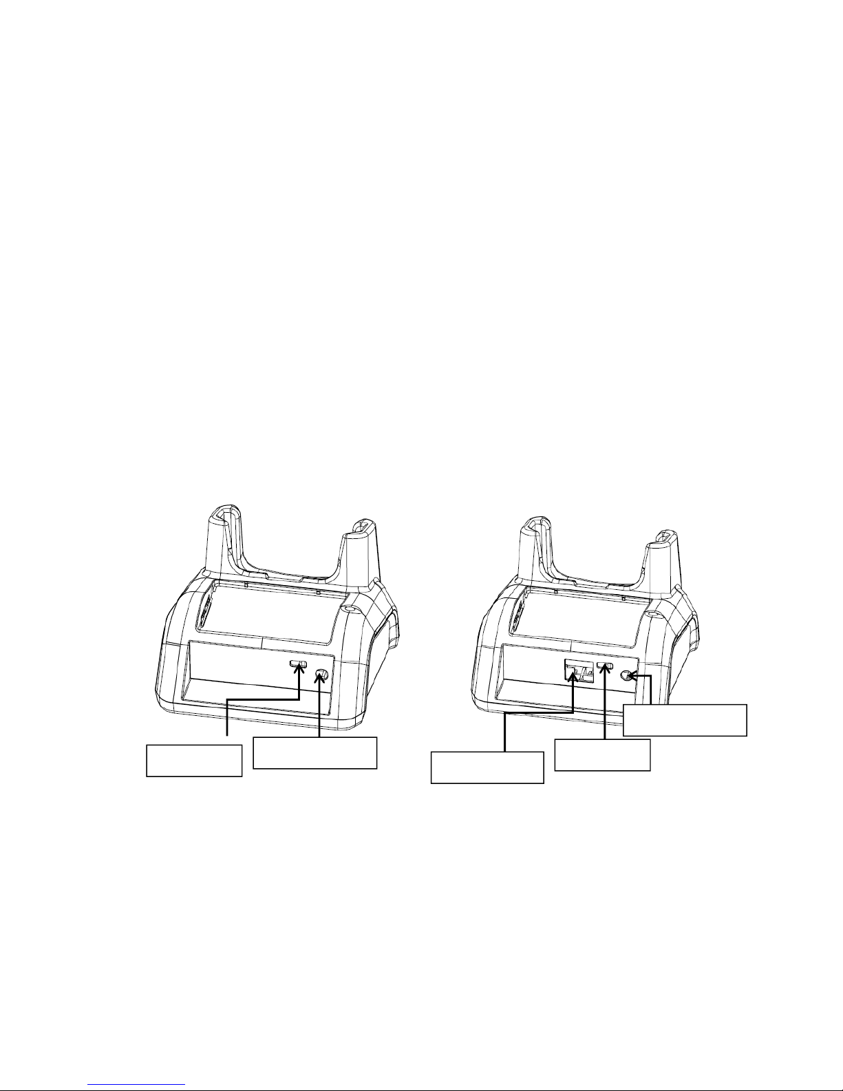
61
Nous recommandons l'utilisation de batteries Li-Ion approuvées par Pointmobile. L'utilisation de toute autre batterie
peut causer des dommages non couverts par la garantie
12.4.
Front Panel
Terminal Well
Place the Handy Terminal in the terminal well to communicate with a host device, power
the terminal, and charge the terminal’s battery. Make sure that the device is securely
seated.
Rubber Feet
The bottom panel has four rubber feet to stabilize the unit on a flat surface. You can set the
base on a dry, stable surface, such as a desktop or workbench near an electrical outlet.
Charging LED
If the LED is red, the unit is charging; if it is green, the charge is complete.
12.5
Back Panel
DC Power Jack
Connect the power cable to this power jack; see powering the Single Slot Cradle Device on
paragraph 12.6.
USB Port
The USB port is full-speed (v2.0). Using the USB cable, you can connect the base to a USB-
compliant device to facilitate USB communication to and from the terminal. USB
communication occurs through Microsoft ActiveSync (v.4.1 or higher). For more information
about ActiveSync setup, see ActiveSync Communication on paragraph 10.4.
Ethernet Port (Single Ethernet cradle only)
Single Slot Cradle
Single Ethernet Cradle
USB port
DC power jack
Ethernet port
USB port
DC power jack
Page 63
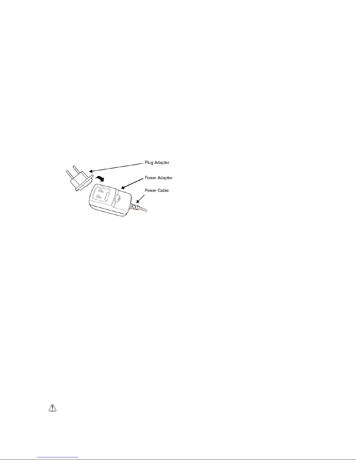
62
Using an Ethernet cable, you can connect the Single Ethernet cradle to an Ethernet-compliant
device to facilitate Ethernet communication to and from the terminal. This equipment is for indoor
use only. The communication wiring is limited to the inside of a building.
12.6.
Powering the Single Slot Cradle or Single Ethernet Cradle
Device
The terminal requires DC 5V input for communication and battery charging; the power adapter on
the power cable converts the voltage from the power source to DC 5V. Only power adapter cables
from Pointmobile convert the voltage appropriately.
The same power cable that ships with each terminal can be used to power the base. This cable
contains a plug adapter for each geography (US, UK, EU, etc.).
1. Attach the appropriate plug adapter to the power adapter.
2. Plug the power cable into the power source.
3. Plug the connector into the DC power jack on the back panel. The base is now powered.
When a terminal is properly seated, the base powers the terminal, charges the ter m inal’s main
battery pack, and launches ActiveSync (see ActiveSync Communication on paragraph 10.4).
Pointmobile recommends that you leave the base connected to its power source at all times, so that
it is always ready to use.
12.7.
Charging the Battery
The base powers the terminal and fully charges the battery pack in 5 hours depending on the
battery.
As battery packs charge, the charging circuitry follows the two-step charging process (CC-CV) that is
recommended for Li-Ion batteries.
The process monitors changes in temperature, current, and voltage.
The battery can be inserted in the battery charging well in back of the terminal connection. Angle
the battery as shown. Once the connectors engage, the LED lights. If the LED is red, the unit is
charging; if it is green, the charge is complete
WARNING:
Do not short-circuit between each contact of the cradle. It may cause fire.
AVERTISSEMENT : Provoquer un court-circuit entre les contacts de la station d’accueil, pourrait provoquer un incendie.
Page 64
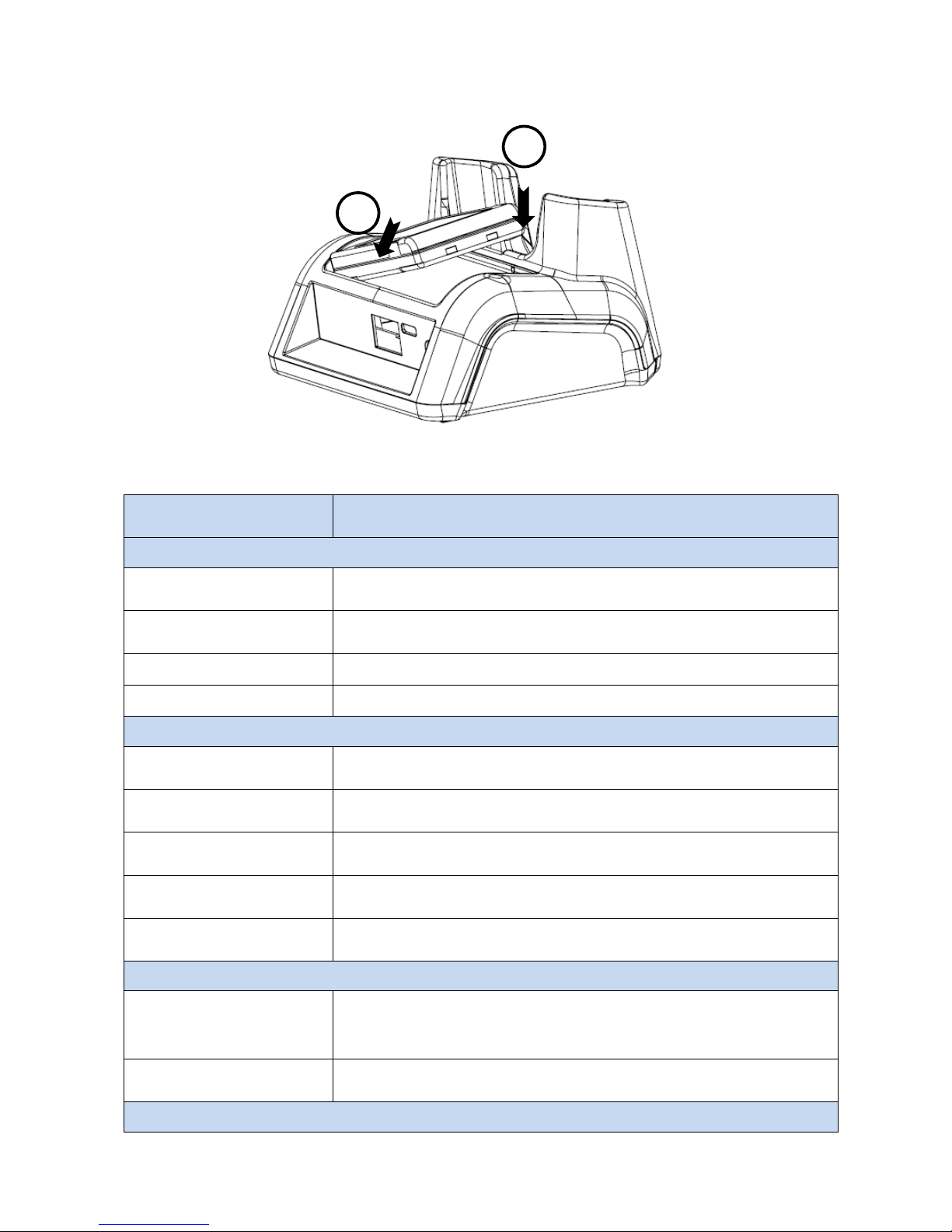
63
12.8.
Technical Specifications for Cradle
Model
60-SSC (Single Slot Cradle)
60-SEC (Single Ethernet Cradle)
Structural
Dimensions 135.5mm(L) x 116mm(W) x 81mm(H)
Weight
Single Slot cradle -
315g
Single Ethernet cradle -
320g
Material Polycarbonate
Color Black
Environmental
Operating Temperature -20° to 55°C
Storage Temperature -25° to +70°C
Charging Temperature
0~45℃ (±3℃)
Electrical Static Discharge
Air:
Direct:
± 15Kv
± 8 kV
Humidity 95% humidity (non-condensing)
Power Supply
Input (Universal)
(from the power source)
AC 100–240 Vac.
50/60Hz 0.9A
Included with Cradle
Output (to the cradle) DC 5V , 4A
Charging
1
2
Page 65
64
Standard Charge Main battery: Standard Capacity:4000mAh (60-BTSC) – Approx. 5hours
Status LED
Green: charged
Red: charging
Communication
Interface
MicroUSB connector supports data transmission of up to 480Mbps OR
Ethernet 10/100BASE-T(support only PM60-SEC)
Agency Approvals
Power Supply
UL listed
TUV licensed
Power Supply compliant to FCC part 15, Class B
Charging
CE Marking (EMC)
CISPR Pub 22
Fire Retardant UL 94- HB
13. 4-Slot Battery Charger
☞
NOTE:
The 4-Slot Battery Charger is option accessory and needed to purchase separately with incidental expenses in
the aftermarket
13.1.
Overview
The 4-Slot Battery Charger device is a four-slot charging station that should charge up to four Li-ion
battery Packs ( standard capacity 4000mAh : 60-BTSC ) in five hours. For more details about
charging, see Battery Charging on page 13-2.
13.2.
Power Supply
The power cable that ships with each charger
WARNING:
We recommend use of Pointmobile peripherals, power cables, and power adapters. Use of any
non-Pointmobile peripherals, cables, or power adapters may cause damage not covered by the warranty.
We recommend use of Pointmobile Li-Ion battery packs. Use of any non- Pointmobile battery may damage not
covered by warranty.
AVERTISSEMENT : Nous recommandons l'utilisation des périphériques, câbles d'alimentation et les adaptateurs
électriques fournis par Pointmobile. L'utilisation de tout autre périphérique, peut causer des dommages non
couverts par la garantie.
Nous recommandons l'utilisation de batteries Li-Ion approuvées par Pointmobile. L'utilisation de toute autre batterie
peut causer des dommages non couverts par la garantie
WARNING:
DO NOT attempt to charge damp/wet handy terminals or batteries. All components must be dry
before connecting to an external power source.
AVERTISSEMENT : NE PAS tenter de recharger des terminaux ou des batteries encore humides ou mouillés.
Tous les pièces et parties doivent être sèches avant la connexion à une source d'alimentation externe
Page 66
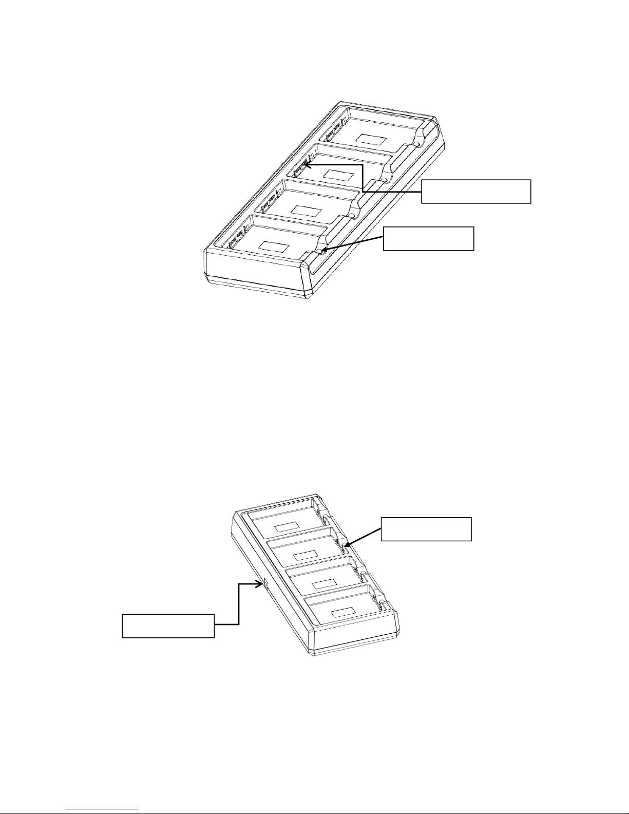
65
13.3.
Front Panel
Charging Slots
The charger contains four charging slots. Each slot holds one battery. When a battery is placed
in a slot, it immediately begins charging and its Status LED lights.
Rubber Feet
The bottom panel has six rubber feet to stabilize the unit on a flat surface. You can set the
charger on a dry, stable surface, such as a desktop or workbench near an electrical outlet.
Charging LED
If the LED is red, the unit is charging; if it is green, the charge is complete.
13.4.
Back Panel
DC Power Jack
Connect the power cable to this power jack; see powering the Single Slot Cradle Device on
paragraph 12.6.
Battery connector
Charging LED
DC power jack
Charging LED
Page 67
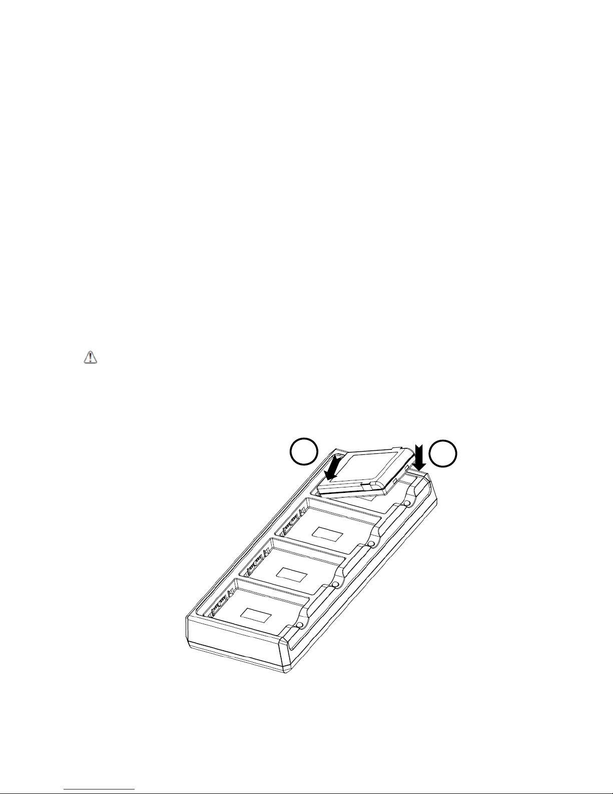
66
13.5.
Charging the Battery
The base powers the terminal and fully charges the battery pack in 5 hours depending on the
battery.
As battery packs charge, the charging circuitry follows the two-step charging process (CC-CV) that is
recommended for Li-Ion batteries.
The process monitors changes in temperature, current, and voltage.
The battery can be inserted in the battery charging well in back of the terminal connection. Angle
the battery as shown. Once the connectors engage, the LED lights. If the LED is red, the unit is
charging; if it is green, the charge is complete
Temperature has a significant effect on charging. For best results, battery packs should be at room
temperature before inserting in the charger.
☞
When the battery temperature exceeds 45°C, the charger may exceed the stated five-hour charge time. The charger
stops charging if the battery temperature is greater than 45°C, but will begin charging again when the battery
temperature is less than 45°C
.
WARNING:
Do not short-circuit between each contact of the cradle. It may cause fire.
AVERTISSEMENT : Provoquer un court-circuit entre les contacts de la station d’accueil, pourrait provoquer un incendie.
1
2
Page 68
67
13.6.
Technical Specifications for
4-slot battery charger
Model 4SBC (4- Slot Battery Charger)
Structural
Dimensions 256mm(L) x 105mm(W) x 37mm(H)
Weight
4- Slot Battery Charger -
434g
Material Polycarbonate
Color Black
Environmental
Operating Temperature -20° to 55°C
Storage Temperature -25° to +70°C
Charging Temperature
0~45℃ (±3℃)
Electrical Static Discharge
Air:
Direct:
± 15kV
± 8 kV
Humidity 95% humidity (non-condensing)
Power Supply
Input (Universal)
(from the power source)
AC 100–240 Vac.
50/60Hz 0.9A
Included with Charger
Output (to the cradle) DC 5V , 4A
Charging
Standard Charge Main battery: Standard Capacity:4000mAh (60-BTSC) – Approx. 5hours
Status LED
Green: charged
Red: charging
Agency Approvals
Power Supply
UL listed
TUV licensed
Power Supply compliant to FCC part 15, Class B
Charging
CE Marking (EMC)
CISPR Pub 22
Fire Retardant UL 94- HB
 Loading...