

Page 1

30 Mobile Computer
with Windows® CE 5.0
User’s Guide
Page 2
1
Getting Started
Out of the Box
Verify that your carton contains the following items:
• mobile computer (the terminal)
• Main battery pack (3.7v, Li-ion)
• AC power supply
• Localized plug adapters
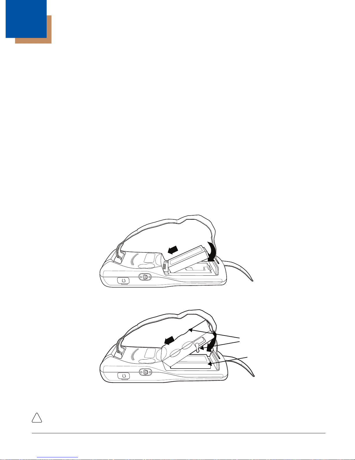
Step 1. Install the Main Battery
PM250 is shipped with the battery packaged separate from the unit. Follow the steps below to install
the main battery.You will need to loosen the hand strap, remove the battery door, insert the battery, and
replace the battery door.
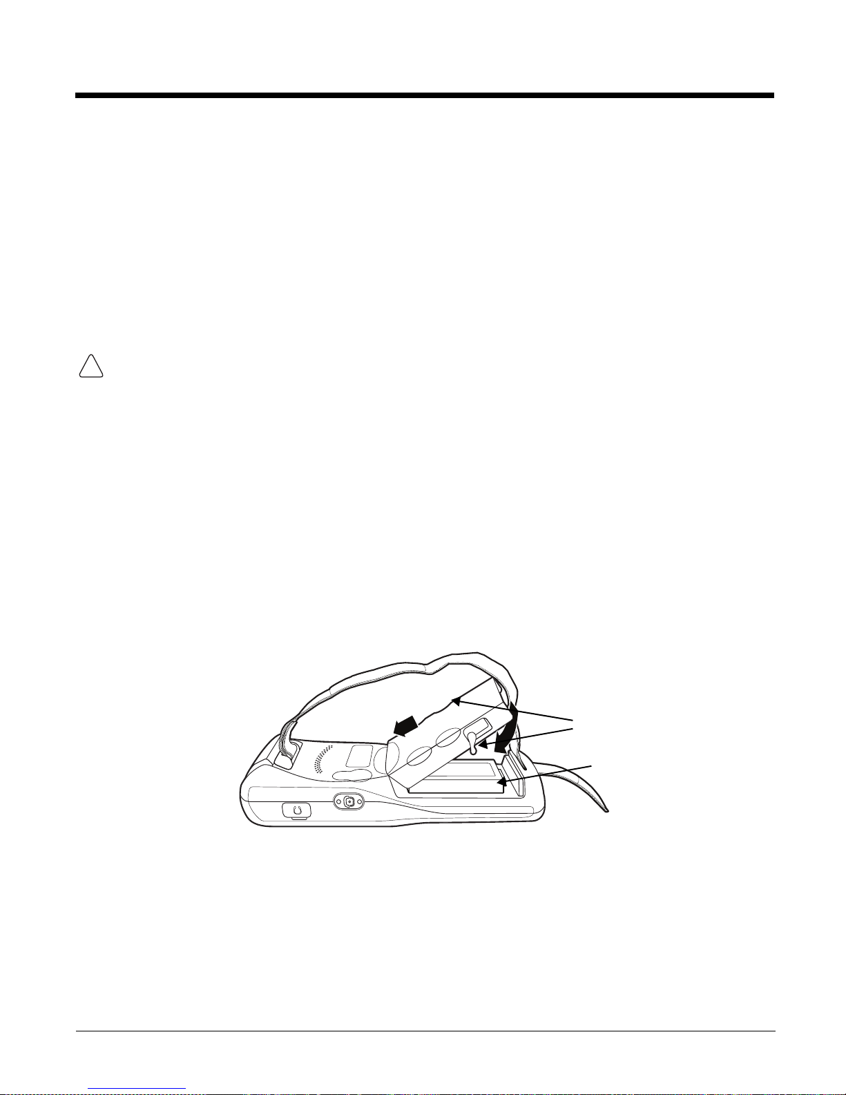
1. Release the strap making it convenient to reach the cover.
2. Remove the battery compartment cover by turning the cover’s pins upward and lifting the cover up.
3. Insert the battery into the battery well with the labels facing upward and the contacts facing
downward.
Q 4. Replace the cover with a hinging motion and turn the pins downwards.
.
Cover Pins
Main Battery
Note: The battery door must be installed prior to booting the unit.
5. Replace the hand strap.
!
Page 3
Step 2. Charge the Batteries
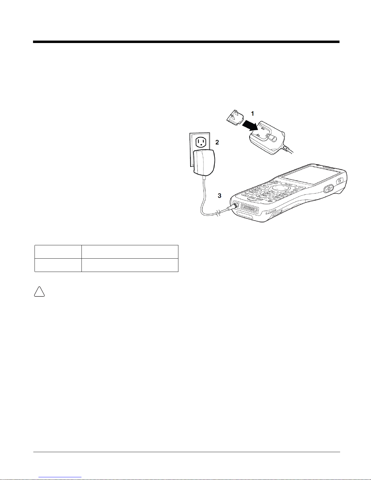
PM250s ship with both the main battery pack and
internal backup battery significantly discharged of
power. Charge the main battery pack with the PM250
charging cable for a minimum of 4 or 6
hours depending on your battery before initial
use.
1. Attach the appropriate plug adapter to the
plug of the power cable.
2. Insert the plug into the appropriate power
source.
3. Plug the power cable into the DC
Power Jack on the bottom
end of the unit.
Note: If you remove the battery pack or it completely
discharges, there is a 30 minute window in which
to insert a charged battery pack before the
backup battery completely discharges. If your
backup battery completely discharges, the
contents of the RAM memory will be lost. If your
backup battery is less than fully charged, there is
a proportionally smaller window of time available.
LED Indicators
Red LED On
Green LED On
Charging
Battery is full or fully charged
We recommend use of PM250 peripherals, power cables, and power adapters. Use of any non-PM250
!
peripherals, cables, or power adapters may cause damage not covered by the warranty.
DO NOT attempt to charge damp/wet mobile computers or batteries. All components must be dry
before connecting to an external power source.
Step 3. Boot the Terminal
The terminal begins booting as soon as power is applied and runs by itself. Do NOT press any keys or
interrupt the boot process.
When the boot process is complete, the Desktop appears, and the terminal is ready for use.
Page 4
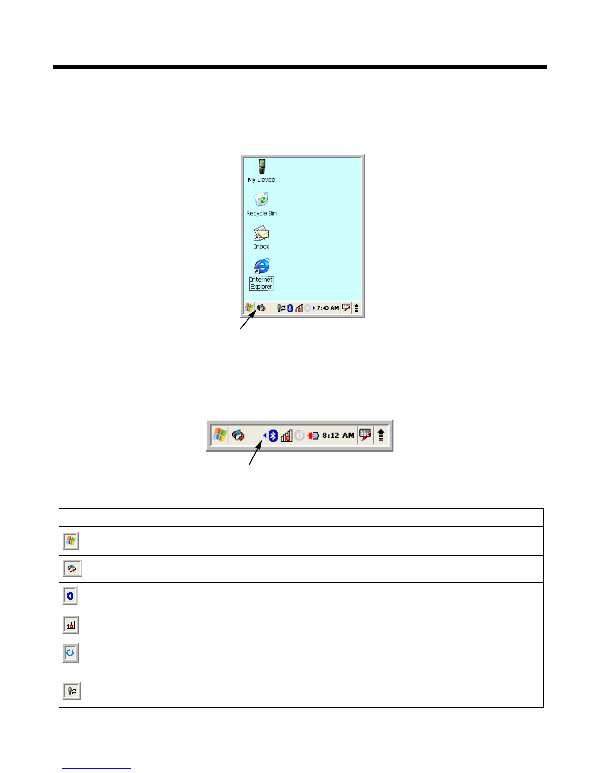
Desktop
Note: You can access the Desktop any time by tapping the Change Views icon in the command bar and selecting
Desktop on the popup menu.
Tap to change
views
Command Bar Icons
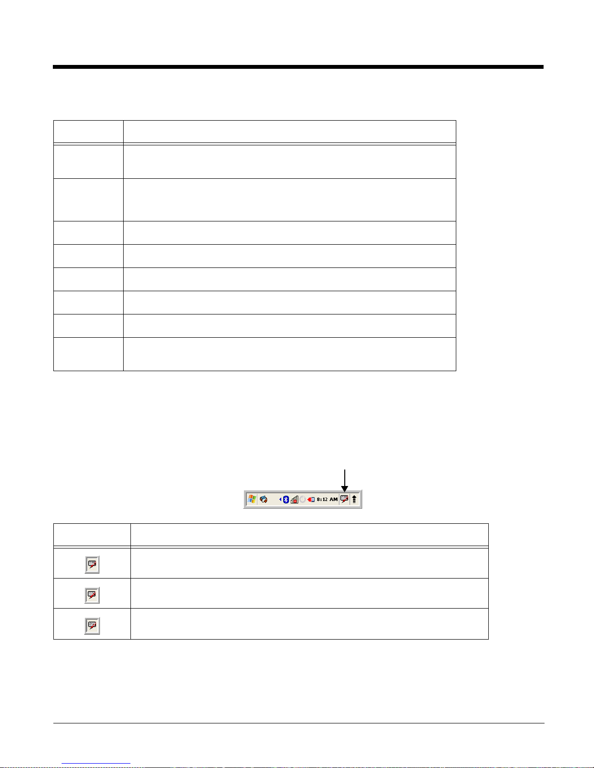
The command bar, located at the bottom of application screens, provides access to many system
functions and programs.
Left and right arrows are used to
scroll through additional icons
Icon Meaning
Opens the Start menu.
Tap to change views between open applications or to return to the desktop.
Accesses the Bluetooth radio. Double tap this icon to open the Bluetooth Manager
Activates the 802.11b/g radio.
Double tap to configure your WLAN Secure Wireless Client.
Indicates that the USB communication cable is connected. Double tap to display USB status
window.
Page 5
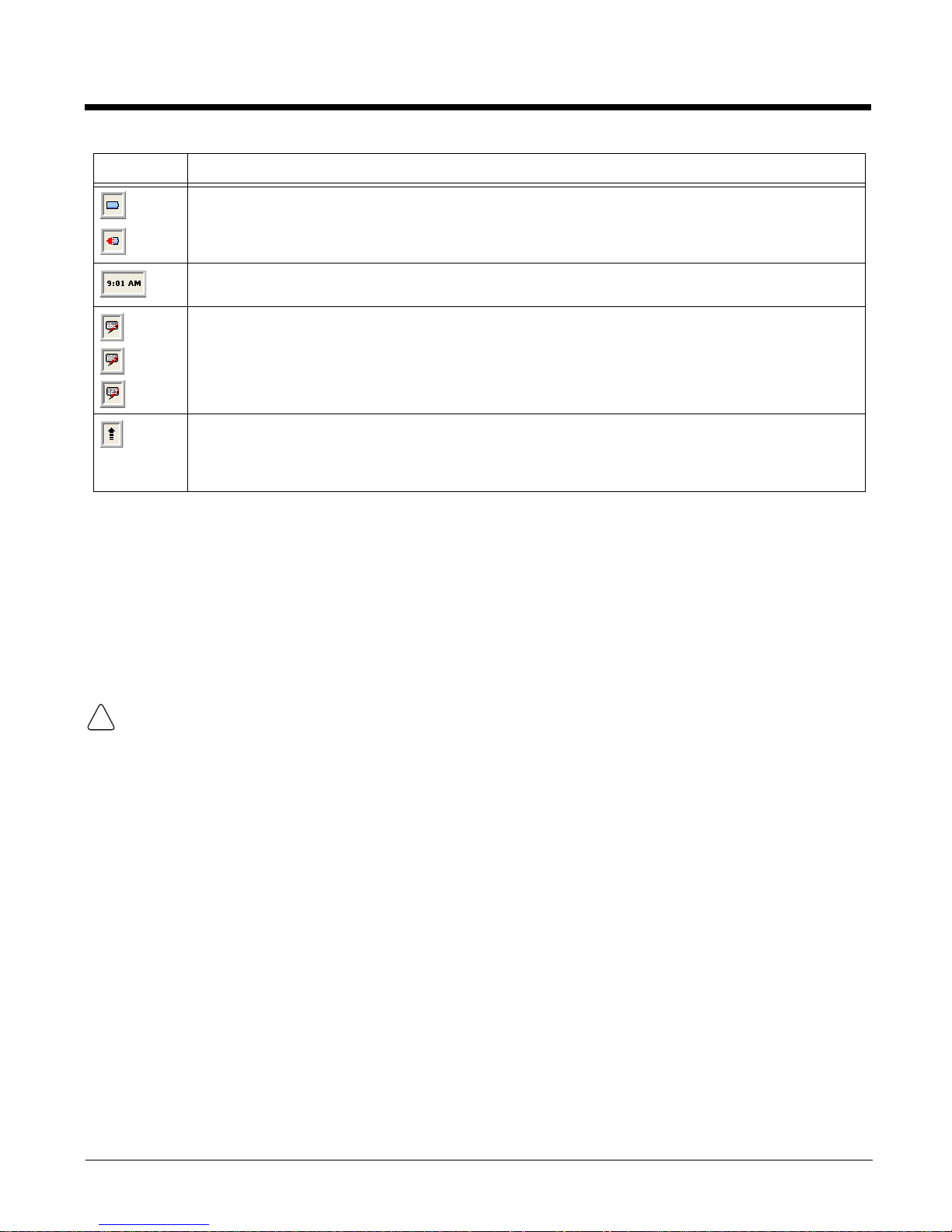
Indicates the status of battery power. Double tap to open the Power control panel setting.
When this icon shows a red power plug, it indicates the device is using external power.
Displays the current time. Double tap to change the time and date.
Indicates whether the keyboard is standard alpha (upper and lower case), all caps alpha, or in
numeric mode. Press the alpha button on the keypad to switch modes.
The up arrow allows you to turn the Wireless LAN and Bluetooth connection on or off. It also
allows you to toggle between the Keyboard and Transcriber. When Keyboard is selected, a
keyboard is displayed so you can tap text and number keys.
Using the Stylus
The terminal comes with a stylus included in a loop on the hand strap. Use this stylus (or your finger) to
select or enter information on the touch screen. The stylus functions as a mouse; generally, a tap is the
same as a click.
Tap Tap the touch screen once or double tap to open menu items and select options.
Drag Hold the stylus on the screen and drag across the screen to select text and images.
Tap & hold Tap and hold the stylus on an item and a pop-up menu appears. On the pop-up menu, tap
the action of the task you want to perform.
Use of objects, such as paper clips, pencils, or ink pens on the touch screen can damage the input
!
panel and may cause damage not covered by the warranty.
Page 6
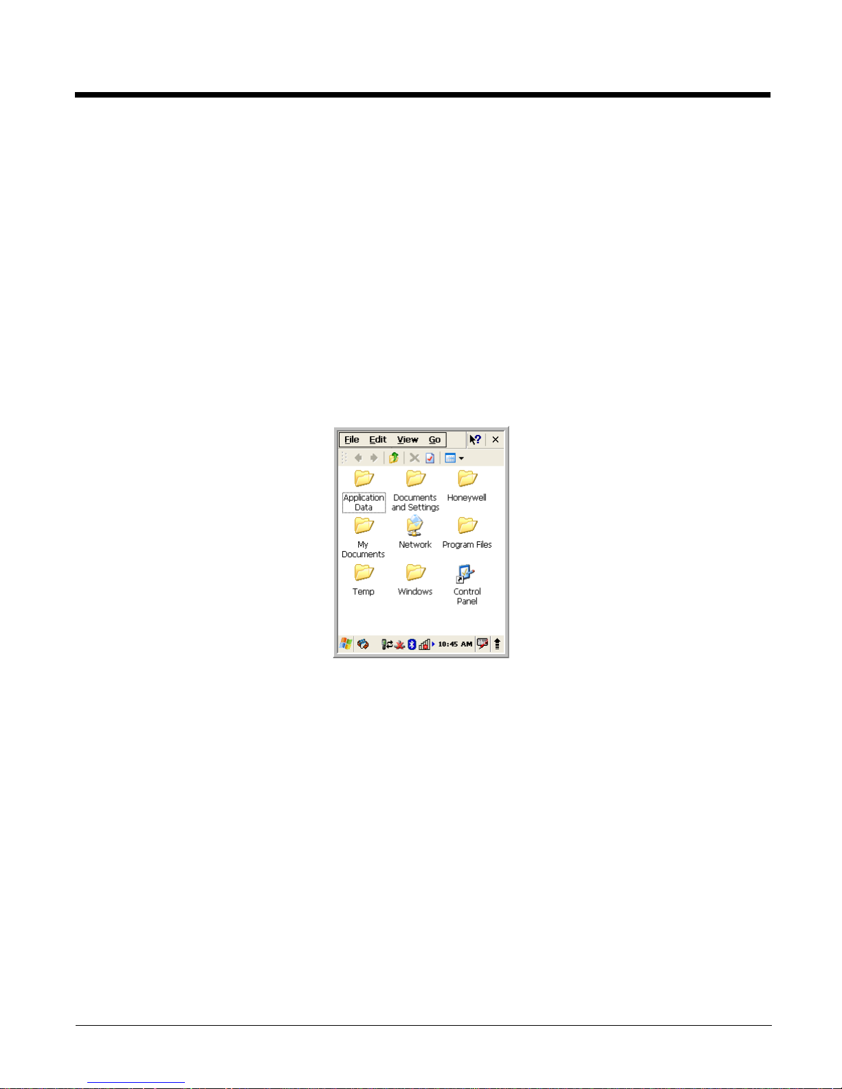
Selecting Programs
Tap Start > Programs. To open a program, tap the icon on the menu.
Pop-Up Menus
You can quickly choose an action for an item using the pop-up menus.
1. Tap and hold the stylus on the item name. The pop-up menu appears.
2. Lift the stylus and tap the action you want to perform.
The contents of pop-up menus change according to the program you are using.
Using Windows Explorer
Use Windows Explorer to navigate through the files on your system. On the desktop, double tap the My
Device icon and Windows Explorer opens to the root level.
Move files by tapping and holding on the file, then tapping Cut, Copy or Paste on the pop-up menus that
appear.
Page 7

2
Terminal Hardware Overview
terminals include a number of standard terminal configurations as well as charging and
communication peripherals and accessories to maximize the efficiency of your application setting.
Standard Terminal Configurations
There is standard configurations: WPAN/WLAN.
• Microsoft Windows CE 5.0
• Marvell PXA 300 624MHz
• 128MB RAM X 128 MB (non-volatile) Memory
• 28-key numeric keyboard
• 2.8” 1/4 VGA transmissive active matrix color
display
• Standard Capacity: Li-ion battery: 3.7V /
2200mAh / 8.1 Wh or Extended Capacity: Li-ion
battery: 3.7V / 3300mAh / 12.2 Wh
• 5300SR image engine
• (WPAN/WLAN) - Bluetooth and 802.11b/g
radio
• power cable
Page 8
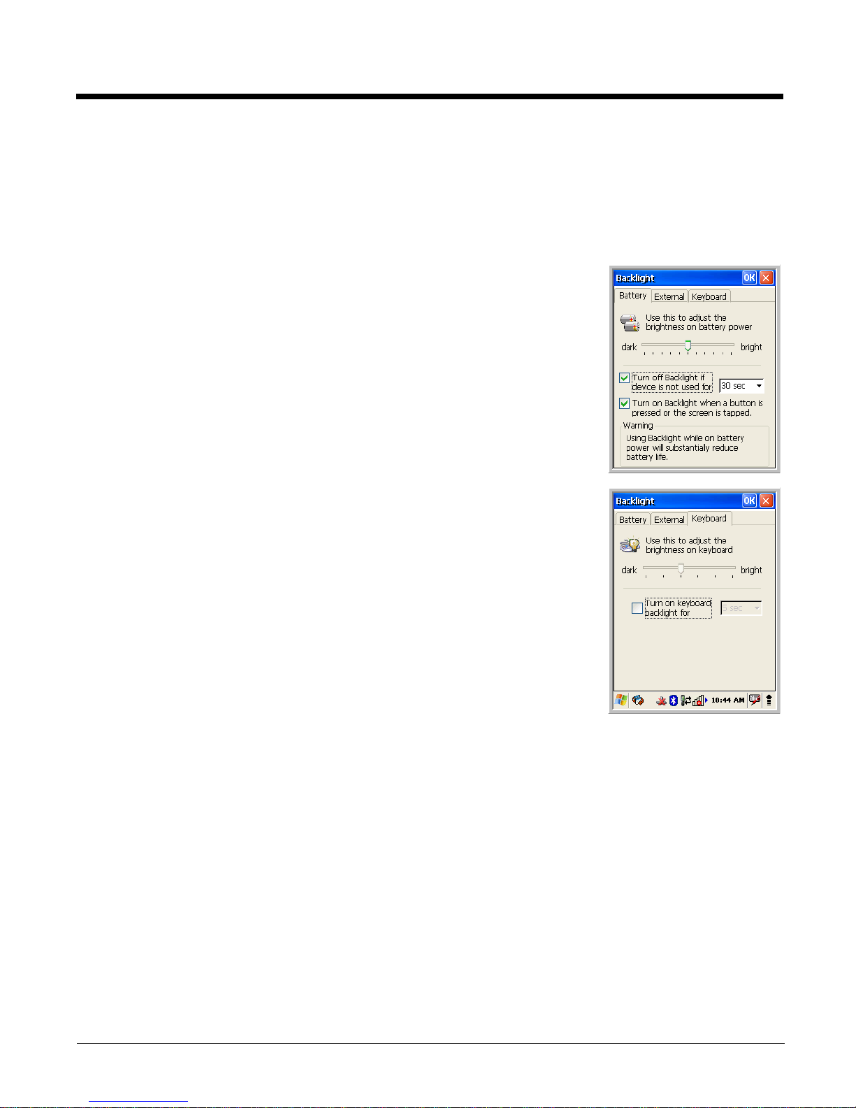
Display Backlight
The intensity of the backlight of the touch screen display may be changed and the backlight may be
programmed to turn off after the terminal has been idle for a specified period of time.
To adjust the intensity of the backlight while on battery power, tap Start > Settings > Control Panel >
double tap Backlight.
Screen Backlight - Battery/External Power
Move the slider to adjust the screen backlight while on battery power.
You may turn the screen backlight off if the device is not used for a designated
period of time by checking the option and designating the desired time period.
You may also turn on the screen backlight when a button is pressed or the
screen is tapped by selecting the appropriate checkbox.
Note: Using the backlight option while on battery power substantially reduces battery
life.
You may make the same changes when on external power by tapping the
External tab.
Keyboard Backlight
The intensity of the backlight of the keys on the keyboard may be changed and
the backlight may be programmed to remain on for a specified period of time
once a key is pressed.
To adjust the brightness of the keys, tap the Keyboard tab. Move the slider
to adjust the backlight while on battery power.
Turn on the keyboard backlight, check the checkbox and change the duration
the backlight.
Page 9
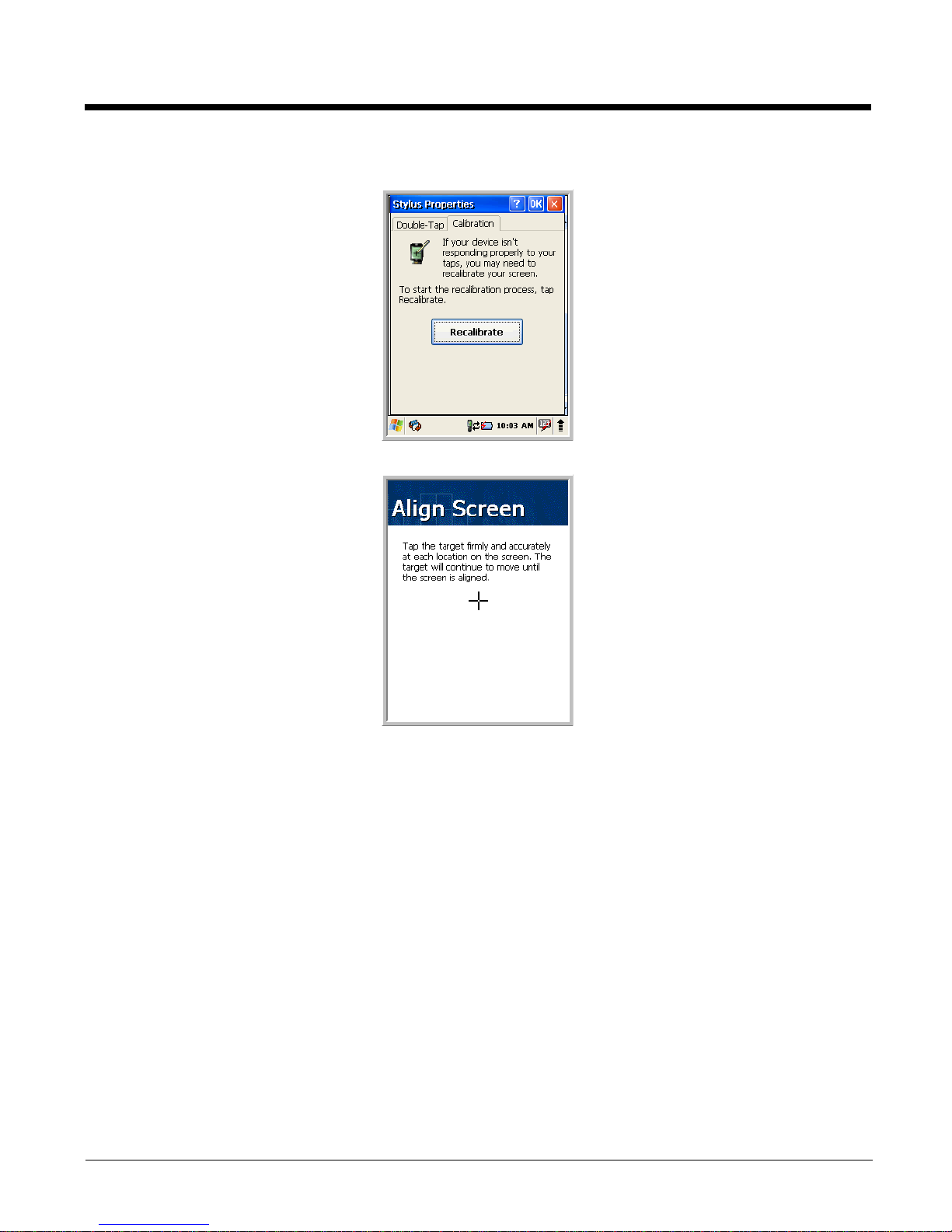
For maximum performance, recalibrate the screen. Tap Start > Settings > Control Panel > double
tap Stylus > Calibration tab.
Tap Recalibrate and follow the instructions on the screen.
Page 10
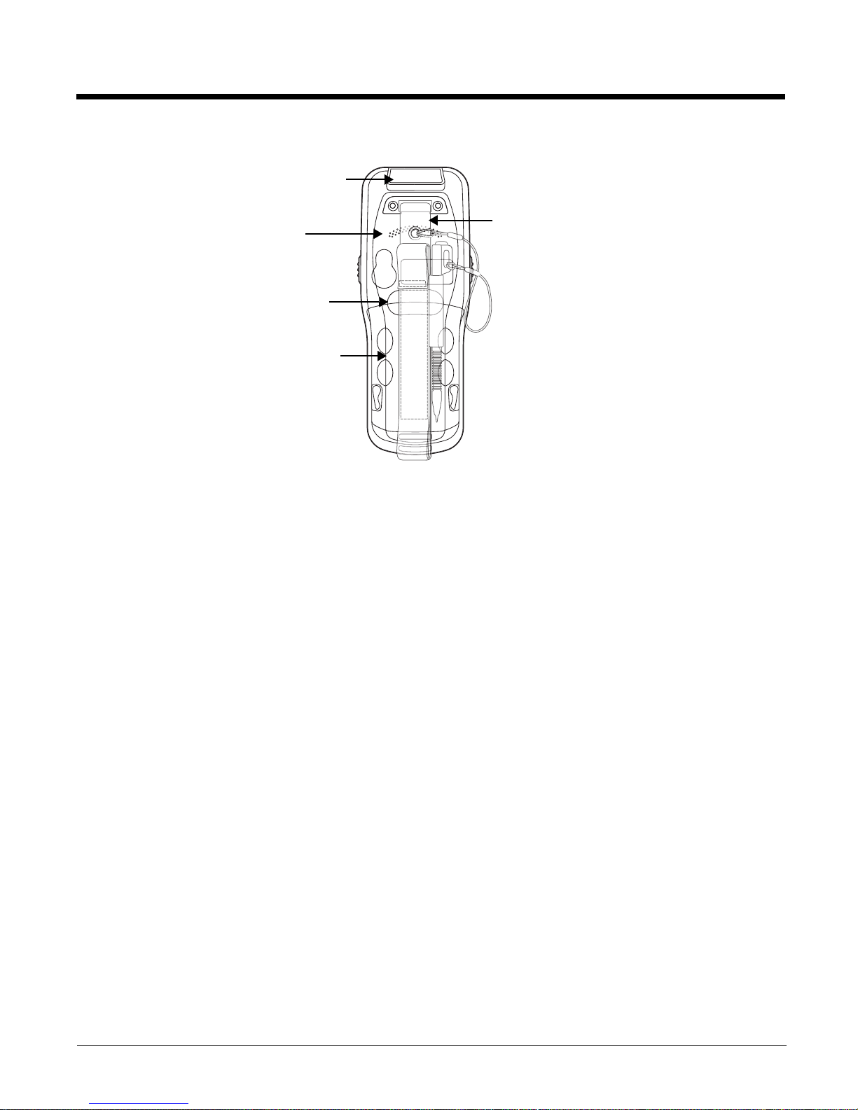
Image Engine Window
Back Panel Features
Installed Battery
Hand Strap
The PM250 comes with an adjustable, elastic hand strap. The strap is attached to the device with
the two small screws. It is threaded through the slot on the bottom of the back of the unit.
Hand Strap (with Stylus)
Speaker
Finger
Saddle
Keep in mind that the hand strap covers the battery. When you want to replace the battery, you
will need to adjust the hand strap accordingly.
Finger Saddle
This is a slightly depressed and angled area of the back housing that is designed to cradle or
“saddle” your pointer finger while holding the terminal. This unique ergonomic design makes
the terminal comfortable to hold and helps prevent you from accidentally dropping the terminal.
Speaker
The integrated speaker sounds audio signals as you scan bar code labels and enter data but
emits no ambient noise on system activity (i.e., processor, memory access, radio traffic, etc.).
The speaker can also be used for playing sounds (e.g., WAV or MP3 files).
The speaker meets the following SPL levels at 40cm:
• 500Hz–67db
• 1KHz–72db
• 4KHz–72db
Stylus
PM250 terminals ship with a stylus inserted in a loop on the hand strap. Store the stylus in the
hand strap when you’re not using it.
Page 11
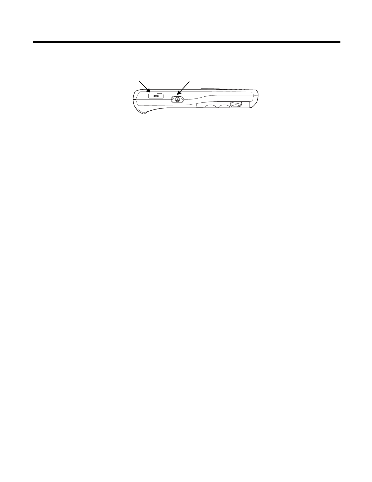
Left Side Panel Features
Micro SD Slot
Side Button
Side Button
There is a button like this on both side panels. You can use the Programs Buttons option in
the Control Panel to change the functionality of the scan buttons.
Side Door
The rubber door on the left side panel provides access to the Micro SD slot.
When closed, the side door seals the terminal from moisture and particle intrusion thus
preserving the terminal’s environmental rating.
Installing Memory Cards
The 250 supports Micro Secure Digital (SD) memory cards of the following capacities:
•2 GB
•4 GB
To install an SD card
1. Press Power key to put the terminal in suspend mode
2. Open the access door on the left side.
3. Insert the SD card with the label facing upward.
Note: To remove an installed SD card while the access door is open, tap on the edge lightly to unlock
the card; the card will pop out just enough for you to grab its edge and pull it out.
4. Replace the access door.
The rubber door is required for 1) proper functioning of the SD card and 2) preserving the
environmental rating for water sealing. Do not remove the rubber door.
Note: Do not use the terminal when the access door is open. When this door is fastened securely and properly, the
memory interface is sealed against moisture and particle intrusion, read/write data is stored securely, and the
terminal’s environmental rating is preserved.
5. Tap the Power key to resume operation.
6. To verify that the operating system recognizes the new memory card, open Windows Explorer and
navigate to My Device\Storage Card.
Page 12
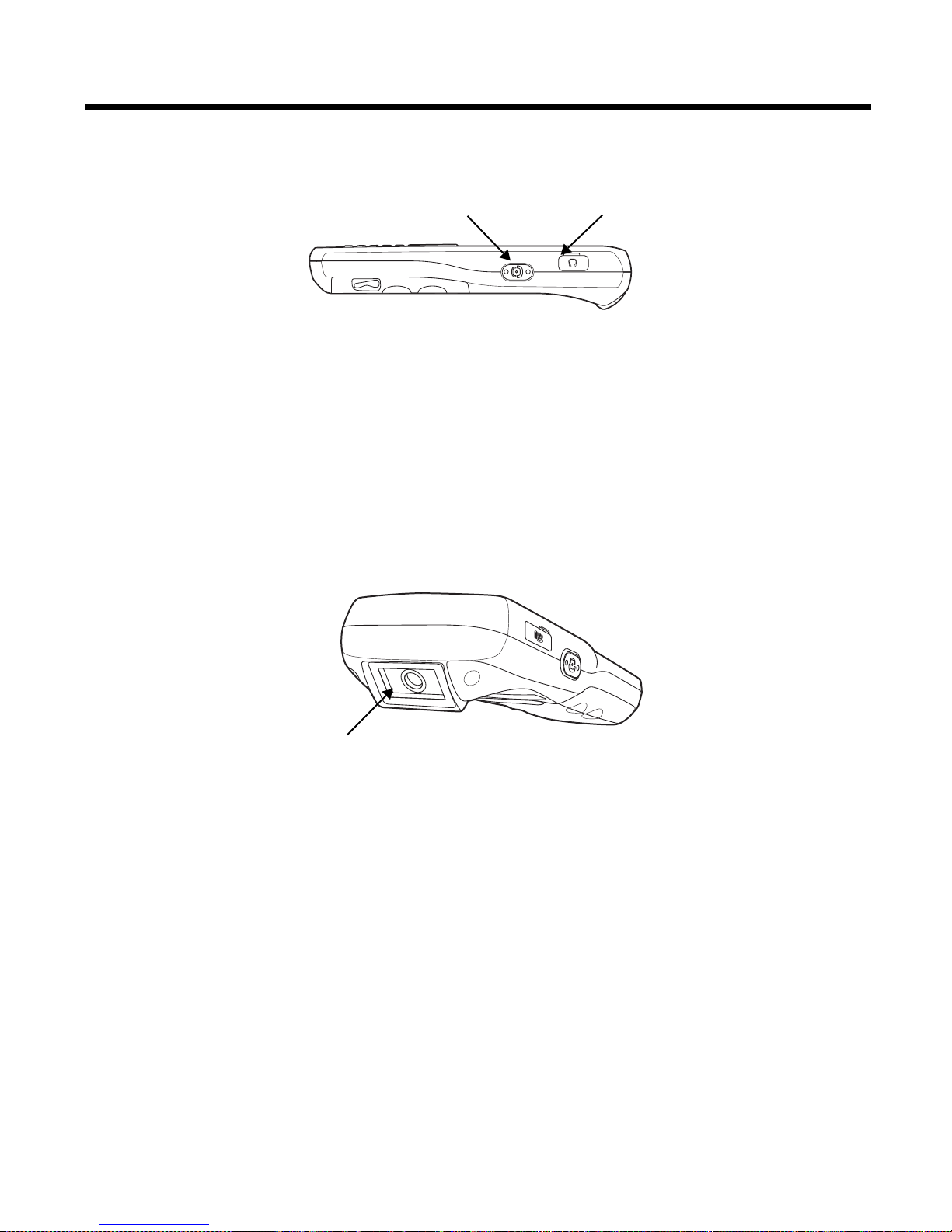
Right Side Panel Features
Headset Jack
The rubber door on the right side panel provides access to the headset jack. This is a 2.5mm
audio jack that supports a headset with a mono speaker and microphone.
When closed, the side door seals the terminal from moisture and particle intrusion thus
preserving the terminal’s environmental rating.
Side Button
There is a button like this on both side panels. You can use the Programs Buttons option in the
Control Panel to change the functionality of the scan buttons.
Top Panel Features
Side Button
Headset
JackS
scan Engine
Window (with engine)
Page 13
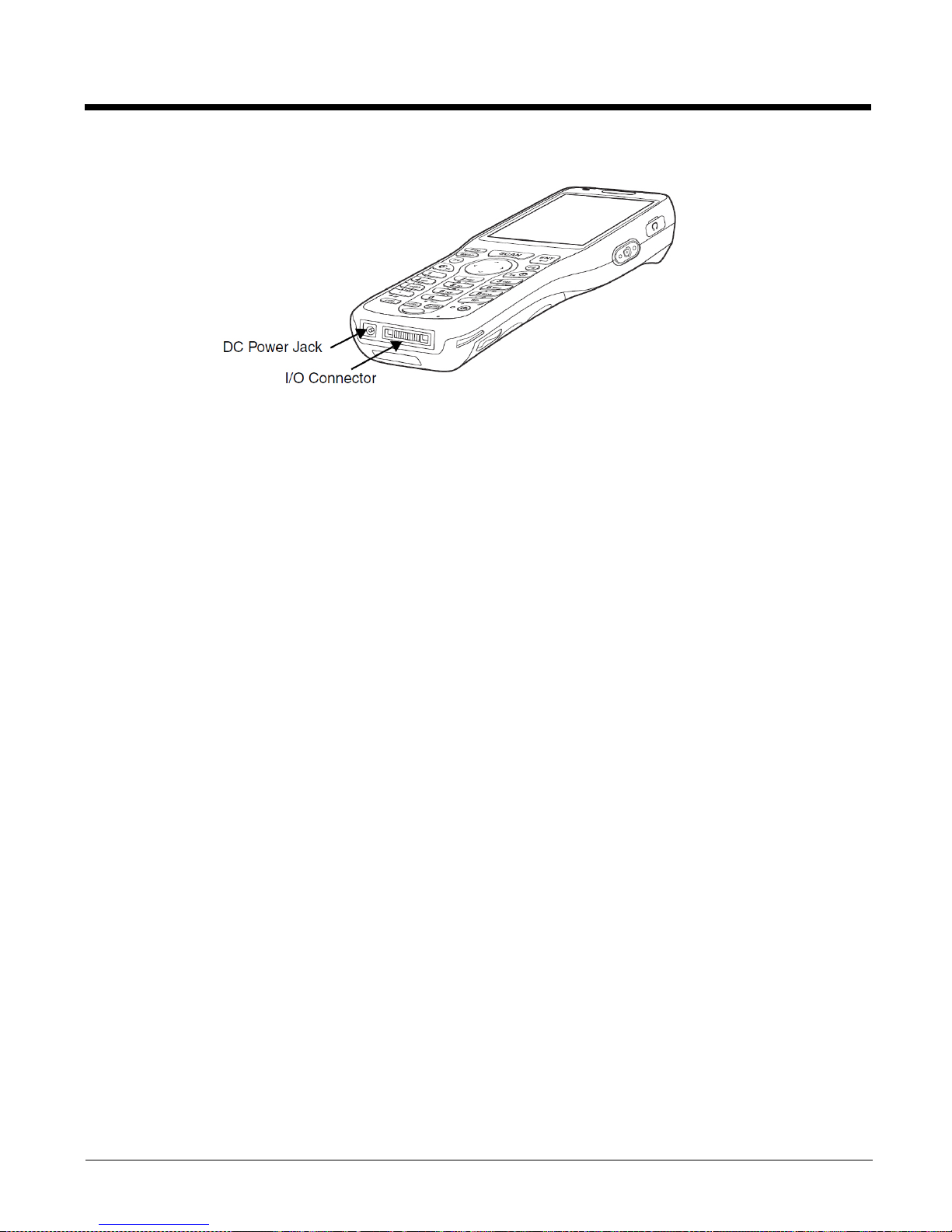
Bottom Panel Features
DC Power Jack
The DC power jack receives external power from the PM250 power cable that comes in the
box with the terminal. When connected to the power cable, the terminal is powered
and the main battery pack is charging.
I/O Connector
The I/O mechanical connector is designed to work exclusively with PM250 peripherals
and cables. This connector powers the terminal, charges the main battery, and facilitates
communication. This connector supports full speed USB 1.1 communication (up to 12 Mbps)
and RS-232 communications with a maximum speed of 115Kbps and seven baud rate
settings.
Through this connector, you can communicate with a host workstation via Microsoft
ActiveSync.
The I/O connector supports the following signals:
• DC IN
• Transmitted Data
• Request To Send
• USB Host +5V
• USB Host D+
• USB Host D-
• USB Host Detect
• Clear To Send
• Received Data
•GND
• RS-232 Shutdown
• USB Client D+
• USB Client D-
• USB Client +5V
Note: Signals referenced are for a DTE device.
Page 14
Battery Power
The intelligent battery technology inside the terminal features two types of battery power:
• The main battery pack on the back panel
• The backup battery located inside the terminal
Both batteries work together to prevent data loss when the terminal is used over long periods of time.
Both batteries must be charged to full capacity before using the for the first time! Charge the
main battery pack with the PM250 charging cable for a minimum of 4 or 6 hours depending on your
battery before initial use.
Main Battery Pack
We recommend use of Li-Ion battery packs. Use of any non -PM250 battery may result in
!
damage not covered by the warranty.
There are two Li-ion battery packs available
Standard Capacity: Li-ion 3.7V/2200mAh/8.1Wh
Extended Capacity: Li-ion 3.7V/3300mAh/12.2Wh
The Li-ion battery packs are the primary power source for the terminal as well as the internal
backup battery.
Changing the Main Battery Pack
Before installing a battery pack, press the Power key to put the terminal in Suspend Mode
so that operations are suspended before removing the main power source. Always put the terminal
in suspend mode prior to changing the battery. The 250 is shipped with the battery separate from the
unit. You will need to loosen the hand strap, remove the battery door, insert the battery, and replace the
battery door. Refer to the instructions included in Installing the Main Battery section.
Note: The battery door must be installed prior to booting the unit.
Charging Options
When the battery is installed in the terminal, you can use any of the peripherals listed below to charge the
battery.
• PM250 Cradle
Page 15
Charging Time
The standard capacity 2200mAh Li-ion battery pack requires four hours to charge to full capacity, while
the extended capacity 3300mAh pack requires six hours.
Managing Main Battery Power
Data and files saved on the 250 terminal may be stored in RAM memory; therefore, maintain a
continuous power supply to the terminal to help prevent data loss. When you remove a battery pack, insert
another charged battery pack in the PM250. If the main battery pack is low, insert the terminal into a
charging peripheral to power the terminal and begin recharging the battery.
Note: If the main battery is low and the terminal is in suspend mode, pressing the Power button does
the PM 250 terminal; you must replace the discharged battery with a fully charged battery.
not
wake
Checking Battery Power
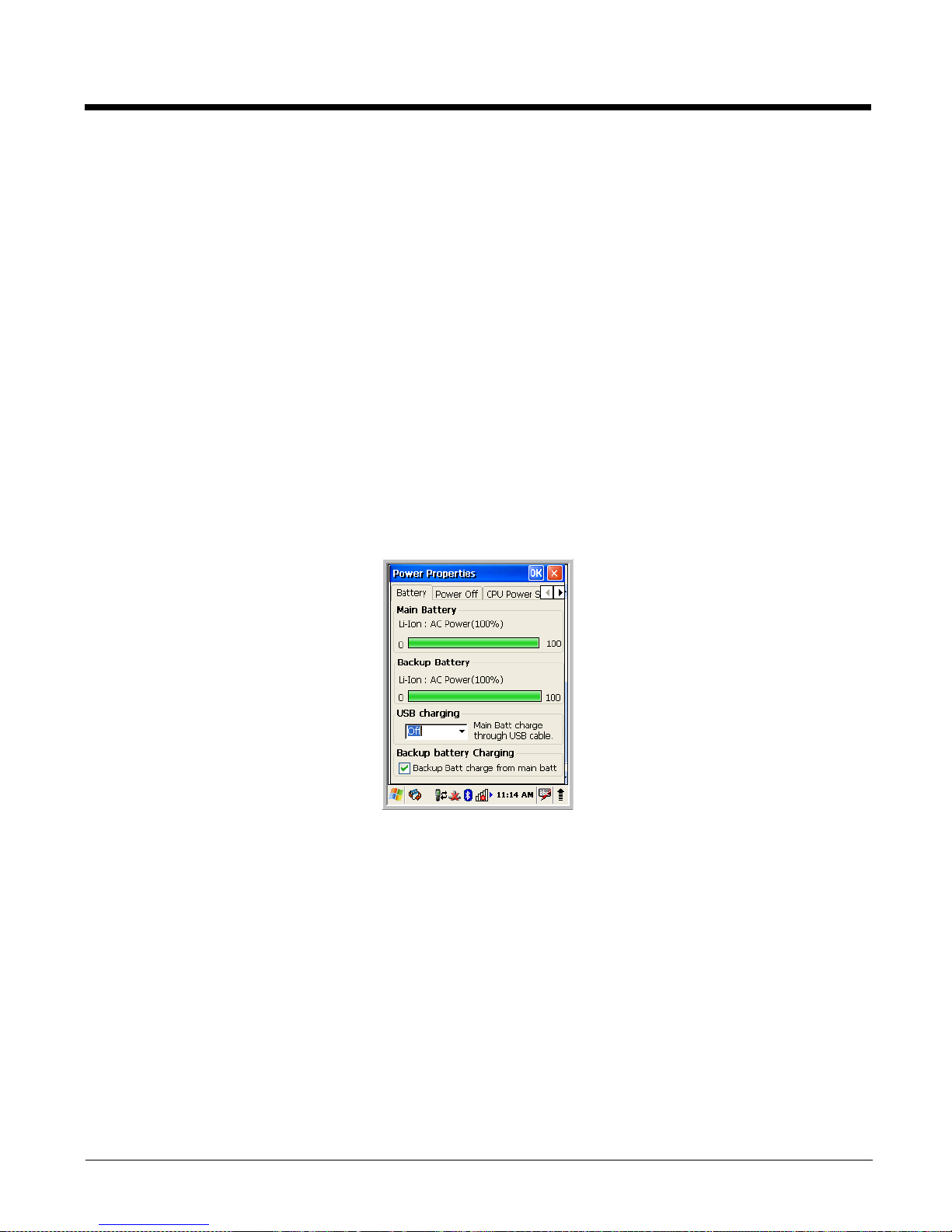
Power icons appear in the command bar at the bottom of the window. Double tap on the battery icon to
open the Power Properties. The Battery tab opens displaying the charge status of both the main and
backup batteries.
Note: To manually check battery power, also tap Start > Settings > Control Panel > double tap Power.
Storage Guidelines
To maintain optimal battery performance, follow these storage guidelines:
• Avoid storing batteries outside the specified range of -4 to 122° F (-20 to 50°C) or in extremely high
humidity.
• For prolonged storage, do not keep batteries stored in a charger that is connected to a power source.
Guidelines for Battery Pack Use and Disposal
The following are general guidelines for the safe use and disposal of batteries:
• We recommend use of PM250 Li-Ion battery packs. Use of any non-PM250 battery may pose a
personal hazard to the user.
• DO NOT attempt to charge damp/wet mobile computers or batteries. All components must be dry
before connecting to an external power source
• Replace defective batteries immediately; using a defective battery could damage the PM250 terminal.
.
Page 16

• Never throw a used battery in the trash. It contains heavy metals and should be recycled according to
local guidelines.
• Don’t use a battery in any other manner outside its intended use in PM250 terminals and peripherals.
• Don’t short-circuit a battery or throw it into a fire; it can explode and cause severe personal injury.
• Excessive discharge damages a battery. Recharge the battery when your terminal indicates low battery
power.
• If you observe that the PM250 battery supplied is physically damaged in some way, send it to PointMobile
or an authorized service center for inspection.
lthough your battery can be recharged many times, it will eventually be depleted. Replace it after the
• A
battery is unable to hold an adequate charge.
Internal Backup Battery
Located inside the terminal, the backup battery is a 3.7V Lithium Polymer battery.
The internal backup battery prevents the terminal from being reset when you remove the main battery
pack. This battery retains RAM data and allows the real-time clock to remain operational for up to 30
minutes. If the terminal is left without the main battery pack for more than 30 minutes, the internal backup
battery discharges and needs to be recharged to function according to specifications.
Note: Even if the internal backup battery fails, data and programs stored in Flash memory or on an
optional SD card are not lost. However, the terminal automatically cold boots when you install a fully charged
battery pack and you need to reset the real-time clock.
Charging
The internal backup battery charges off the main battery pack and requires 2 hours charge time to backup
RAM data for 30 minutes. You can begin using the terminal after charging the main battery for
four or six hours (depending upon your battery); however, the internal backup battery will continue to
charge off the main battery.
To ensure that the internal backup battery functions properly, maintain a consistent power supply for the
first eight hours of terminal operation. This power supply can be external power (using a charging
peripheral) or an installed, charged battery pack or a combination of both.
Charging Guidelines
Follow these guidelines to maximize the life of the PM250’s internal backup battery:
• Keep a charged Li-ion battery pack in the terminal.
• Keep the PM250 terminal connected to a power source when the terminal is not in use.
Page 17

Resetting the Terminal
Soft Reset: Using the stylus press and release the Reset button. This resets RAM and reloads the OS.
Hard Reset: Using the stylus press and hold the
This resets RAM, reloads the OS, and resets the Real Time Clock.
Reset button and then press and release the Power button.
Soft Reset (Warm Boot)
A soft reset re-boots the terminal without losing RAM data and launches Autoinstall, which re-initializes
the terminal.
You would perform a soft reset 1) when the terminal fails to respond, 2) after installing software
applications that require a reboot, or 3) after making changes to certain system settings.
1. Press the Reset button. The screen turns white and the decode and scan LED flashes blue for
approximately three seconds.
2. When the reset is complete, the Desktop appears.
Hard Reset (Cold Boot)
A hard reset erases all of the data and applications stored in RAM memory and launches Autoinstall, which
re-initializes the terminal.
!
Hard resets automatically launch a soft reset as part of the boot process.
1. Press and hold the Reset button and then press and release the Power button. The screen turns
white and the decode and scan LED flashes red for approximately three seconds.
Note: Set the time and date after each hard reset to ensure that the system clock is accurate. Double-click the date
on the command bar to open the Clock setting and set the time and date.
Suspend Mode
Suspend mode suspends terminal operation. The terminal appears to be “off” when in suspend mode.
The terminal is programmed to go into suspend mode automatically when inactive for a specified period
of time. You can set this time period in the Power setting.
To suspend and resume operation, press the Power button.
Note: You should always put the terminal in suspend mode when you change the battery pack;
Troubleshooting Suspend/Resume
If the terminal does not wake when you press the Power button, the main battery might be too low to
resume operation. To check, remove the battery and install a fully charged battery or connect the terminal
to a PM250 charging peripheral.
Changing the Memory Allocation
You can adjust file storage vs. program memory in System Properties.
Page 18
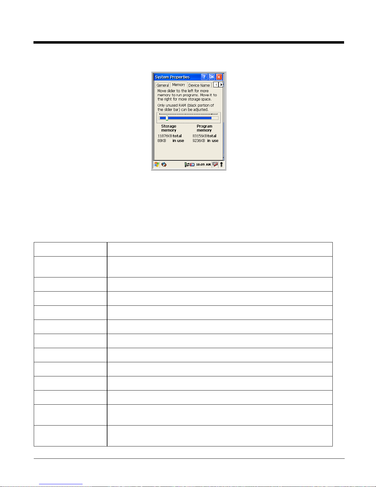
1. Tap Start > Settings > Control Panel > System > Memory tab.
2. Move the slider to adjust the memory allocation and tap OK. The changes take effect immediately.
Care and Cleaning of the Terminal
When needed, clean the image engine window and the LCD display with a clean, non-abrasive, lint-free
cloth. The terminal can be cleaned with a damp cloth.
Technical Specifications
Operating System Microsoft Windows CE 5.0
Development
Environment
Application Software Tools and Demos
Processor Marvell PXA 300 624MHz
Memory 128MB RAM X 128 MB Flash
Expansion Slot User accessible Micro SD Card up to 4 GB with SDIO support
Display 2.8 in. transmissive active matrix 65K color LCD with backlight, QVGA (240 x 320)
6FDQ Engine6\PERO'5300SR 2D VGA Area Imager with High-Vis bracket aimer
Keyboard 28-key shifted alpha numeric with backlit keys
Voice Communication Voice-over-IP and Push-to-Talk ready
Audio Built-in microphone and speaker, stereo headset jack
Communication
Interface
SDK for Windows® CE 5.0
Full speed USB 1.1 from cradle (or I/O cable); RS232 (115 Kbps) from cradle
Battery Standard Li-ion battery 3.7V / 2200 mAh / 8.1 Wh
Extended Li-ion battery 3.7V / 3300 mAh / 12.2 Wh (includes extended battery door)
Page 19
Expected Hours of
8+ hours (with scan and continuously transmitting)*
Operation
Charging 5V/3A input through bottom access or USB/Serial connector
Expected Charge Time Standard Capacity: 2200mAh - four hours
Extended Capacity: 3300mAh - six hours
Charging Peripherals AC wall adapter and Charge
r )/Communication Cable
HomeBase–single-bay terminal charge
Quad Charger–four-slot battery pack charger (DSA-0421S-03 1)
WPAN (standard) Bluetooth Class II (10 m) v2.0 Enhanced Data Rate (EDR) with on-board antenna. BQB
certified
WLAN Dual Mode 802.11 b/g (11 Mbps/54 Mbps) with internal antenna
WLAN Security WEP,
802.1x, LEAP, TKIP, MD5, EAP-TLS
, EAP-TTLS, WPA-PSK, WPA v2.0, PEAP
Operating Temperature 14° to122°F (-10° to 50°C)
Charging Temperature 32° to 104°F (0° to 40°C)
Storage Temperature -4° to 158°F (-20° to 70°C)
Humidity 95% humidity, non-condensing
Construction High impact resistant PC/ABS housings
Magnesium alloy internal chassis with component shock mounts
Drop 4 ft. (1.2m) multiple drops to concrete, all axis, across operating temperature range
Tumble 500 3.3 ft (1.0m) tumbles (1,000 drops)
ESD Air: ± 15k Vdc
Direct: ± 8k Vdc
Environmental IP64 rating
Dimensions 175 mm long x 66 mm wide x 26.8 mm deep (6.8” x 2.60” x 1.06”)
Weight 250 g (8.8 oz) including standard battery pack
Scanner / Decode
Capabilities
5300SR 2D Imager with Adaptus Technology and Laser Aimer. Decodes all standard 1D,
2D, Postal, and OCR codes.
Regulatory and
Compliance
* For standard battery pack. Battery life varies with application and use case.
Page 20
3
Using the Keyboard
Overview
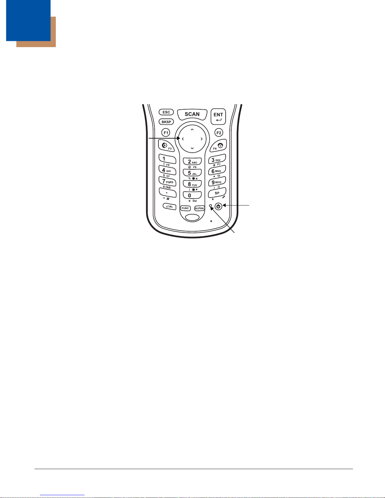
The numeric keyboard is as follows:
Navigation
keys
Power key
Software
Reset key
Navigation Keys
Located in the center of the keyboard for easy access with either hand, the navigation keys enable you
to move the cursor up and down lines and from character to character.
Page 21
Basic Keys
Name Function
ALPHA Toggles the keyboard between alpha (upper and lowercase) and numeric
modes. Indicator changes accordingly on the command bar.
Backspace Backspace moves the cursor back one space.
If you are typing text, a character is deleted each time you press the
backspace key.
Control Modifies the next key pressed to type specific characters.
Escape Cancels an action.
Enter Performs the same function as the Enter key on a workstation.
Power Suspends and resumes the terminal.
Scan Activates the image engine to scan a bar code or take an image.
Space Moves the cursor one space forward.
If you are typing text, it moves the text one space forward as well.
Alpha/Numeric Modes
The keyboard defaults to numeric mode. Use the ALPHA key to toggle between numeric and alpha
modes. Pressing the ALPHA key once locks the keyboard in numeric mode, alpha mode (lowercase), or
alpha mode (uppercase).
The command bar on the screen displays an icon that indicates the alpha/numeric status of the keyboard.
Icon Keyboard Status
The keyboard is in lowercase alpha mode.
The keyboard is in uppercase alpha mode.
The keyboard is in numeric mode.
Alpha Indicators on the Number Keys
Each number key displays the characters typed when you press that key in alpha mode.
Page 22
Note that when typing in alpha mode, you must use the same multi-press method you would use when
typing letters on a phone keypad. Each key press types the next letter in the sequence as displayed by
the alpha indicator.
Function Key Combinations
The Function key (FUNC) modifies the next key pressed to perform specific functions.
Key Combination Function
FUNC + 1 F5
FUNC + 2 F6
FUNC + 3 F7
FUNC + 4 Toggle the wireless radio on and off
FUNC + 5 Increase screen brightness
FUNC + 6 Increase volume
FUNC + 7 Ta b
FUNC + 8 Decrease screen brightness
FUNC + 9 Decrease volume
FUNC + . Start menu
FUNC + 0 Delete
FUNC + SP Align the screen
(Press ESC to exit)
The keyboard is color-coded in blue to indicate these key combinations.
Note: The color-coded indicators are located below each key.
Page 23
CTRL Key Combinations
The Control key (CTRL) modifies the next key pressed to type specific characters.
Key Combination Function
CTRL + 1 !
CTRL + 2 @
CTRL + 3 #
CTRL + 4 $
CTRL + 5 %
CTRL + 6 ^
CTRL + 7 &
CTRL + 8 (
CTRL + 9 )
CTRL + . - (minus)
CTRL + 0 *
CTRL + SP + (plus)
The keyboard is color-coded in yellow to indicate these key combinations.
Note: The color-coded indicators are located below each key.
Program Buttons
Buttons can be programmed to execute different functions using the Program Button program in the
Control Panel. The following buttons on the 250 are programmed for the listed function. Press and hold
the Function (FUNC) key and press the appropriate function key to execute the indicated function.
Key Combination Function
F1 WordPad
F2 Email
F3 Windows Explorer
F4 Internet Explorer
F5 Pocket CMD
F6 Control Panel
F7 Transcriber
Page 24

Supported Bar Code Symbologies
Symbology Type Symbology Name
1D Symbologies Codabar
Code 3 of 9
Code 11
Code 32 Pharmaceutical (PARAF)
Code 93
Code 128
EAN with Add-On
EAN with Extended Coupon Code
EAN-13
GS1 Databar
2D Symbologies Aztec
Code 16K
Composite
Data Matrix
Grid Matrix
GS1 Databar
Han Xin
MaxiCode
OCR
PDF417
QR Code
Composite Codes Aztec Mesa
Codablock F
EAN·UCC
GS1 Databar-14
OCR OCR-A
OCR-B
OCR-US Money Font
Interleaved 2 or 5
Matrix 2 of 5
Plessey
PosiCode
Straight 2 of 5 IATA
Straight 2 of 5 Industrial
Telepen
Trioptic Code
GS1-128
UPC and UPC-A
Postal Codes Postnet and most international 4 state codes
Australian Post
British Post
Canadian Post
China Post
Japanese Post
KIX (Netherlands) Post
Korea Post
Planet Code
Page 25

Activating the Engine
When a scanning application is open, press the Scan key to activate the image engine.
Using Demos
Demos are software utilities loaded on all terminals that demonstrate the advanced
features of the terminal. There are two Demos that feature the image engine: Image Demo and Scan
Demo.
To access these demos, tap Start > Programs > Demos.
•Select Scan Demo to verify decoding, or
•Select Image Demo to verify imaging.(2D)
To Decode a Bar Code
1. Tap Start > Programs > Demos > Scan Demo.
2. Position the PM250 terminal over one of the sample bar codes
A range of 4–10 inches (10–25 cm) from the bar code is recommended.
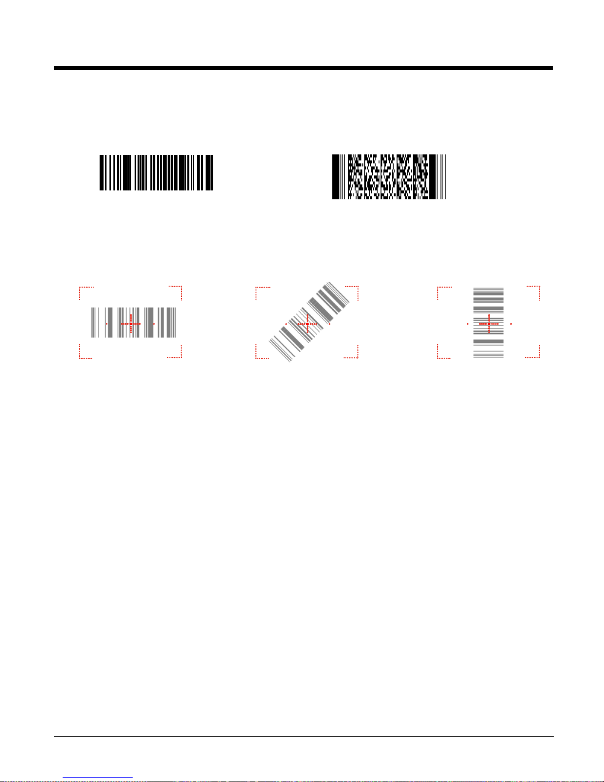
3. Project the aiming brackets by pressing and holding the Scan key. The Scan LED lights red
4. Center the aimer crosshair over the bar code. The aiming beam should be oriented in line with the
bar code to achieve optimal decoding; Omni-Directional Scanning Positions (2D)
5. When the bar code is successfully decoded, the decode LED lights green and the terminal beeps.
.
Page 26
Sample Bar Codes
You can use the following bar codes to verify decoding:
Sample 128 Sample PDF417 (2D)_Option
Code 128
PDF417 Test Message (2D)_ Option
Omni-Directional Scanning Positions
The high-vis aiming pattern frames the bar code to provide you with the best scanning performance.
Note: To achieve the best read, the aiming beam should be centered horizontally across the bar code.
The aiming pattern is smaller when the terminal is held closer to the code and larger when the terminal is
held farther from the code. Symbologies with smaller bars or elements (mil size) should be read closer to
the unit whereas larger bars or elements (mil size) should be read farther from the unit.
Page 27

4
Communication
Communication Options
terminals offer communication options including Microsoft ActiveSync
I/O Connector (Wired Communication)
The mechanical connector on the bottom panel or using a Cradle of POM250
Page 28
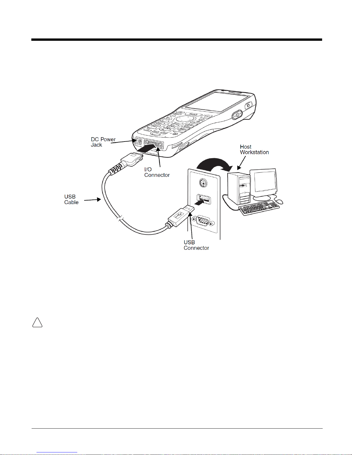
Connecting the USB Cable
Connect the USB cable to the I/O connector to facilitate USB communication between the PM250
terminal and the host workstation.
ActiveSync Communication
To synchronize, ActiveSync 4.1 or higher must be installed and configured for the appropriate
communication type on the host workstation and the terminal. PM250 terminals ship with
ActiveSync already installed. Therefore, if ActiveSync is already installed on the host workstation, you just
need to connect the PM250 terminal to the host workstation (via peripheral) to initiate
communication.
Note: You can download the most current version of ActiveSync from www.microsoft.com.
When communicating via ActiveSync, your terminal is designed to be connected to the host workstation with
a communication peripheral. We recommend use of peripherals, power cables, and
!
power adapters. Use of any non- PM250 peripherals, cables, or power adapters may cause damage not
covered by the warranty.
Communication Type
The 250 supports the following type of communication via ActiveSync through its DC Power Jack
on the bottom panel:
USB The USB cable and hardware peripherals allow the terminal to communicate with
a workstation or to networked through a USB hub. The terminal supports full-speed
USB communication (USB 1.1); maximum data transfer rate is 12 Mbps. The 250
terminal defaults to USB communication out of the box.
Page 29
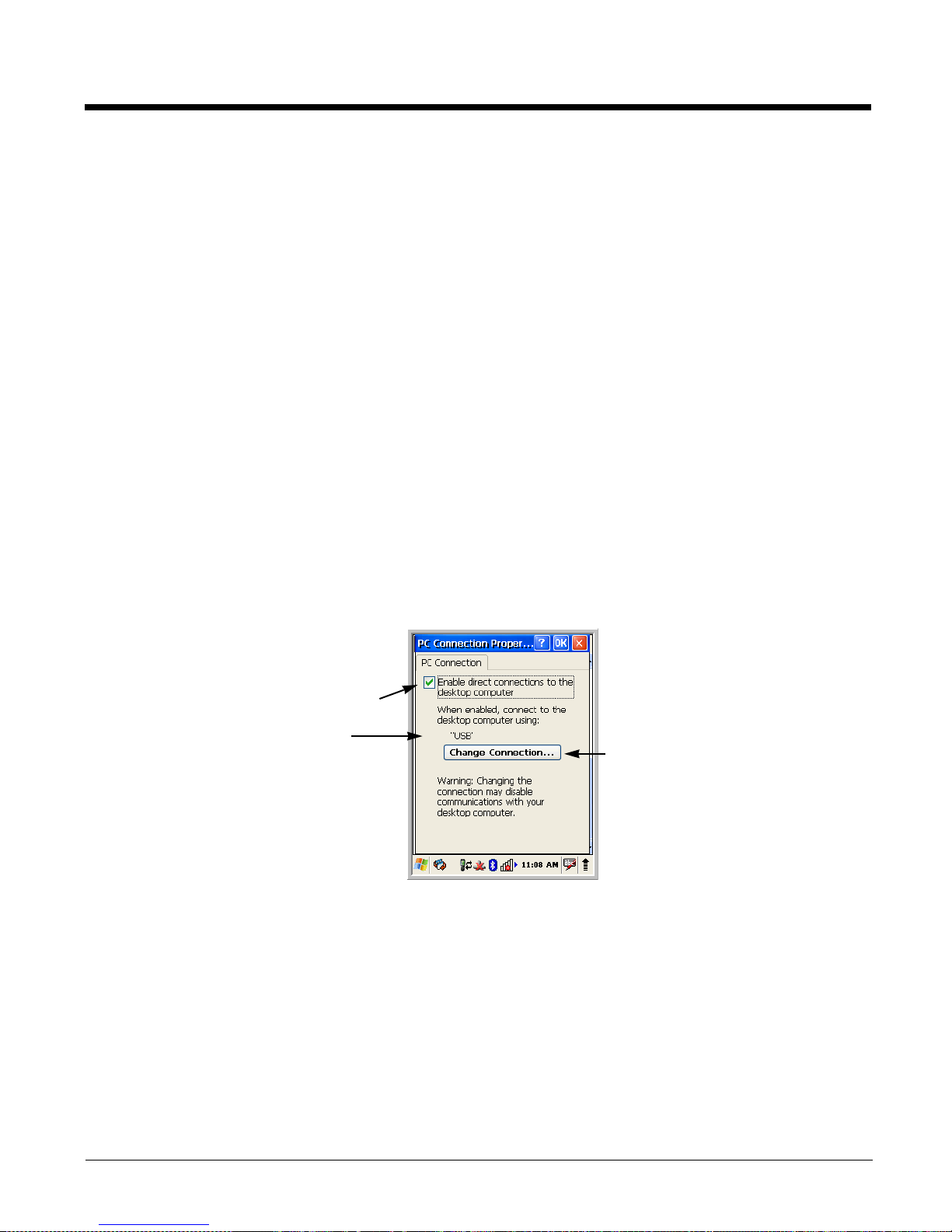
Hardware Requirements for Setup
Displays the current connection setting
Tap to change the connection settings
Must be checked to connect to a workstation
• communication peripheral
• power cable
• USB Cable (for USB communication)
• ActiveSync v4.1 or higher installed on the host workstation
• Windows 98 Second Edition, Windows Me, Windows 2000, Windows NT (4.0 SP6 or higher) or
Windows XP computer.
Software Requirements for Communication
To sync successfully, ActiveSync must be configured for same communication type on both the host
workstation and the 250 terminal. ActiveSync must be setup on your workstation
before
you initiate
synchronization from the terminal for the first time.
Setting Up the Host Workstation
Verify that ActiveSync is configured to use the appropriate communication type by clicking File >
Connection Settings.
For USB communication, check Allow USB connections.
Setting Up the Terminal
The terminal defaults to USB communication out of the box. To verify and/or change the default
setting, tap Start > Settings > Control Panel > PC Connection.)
Page 30
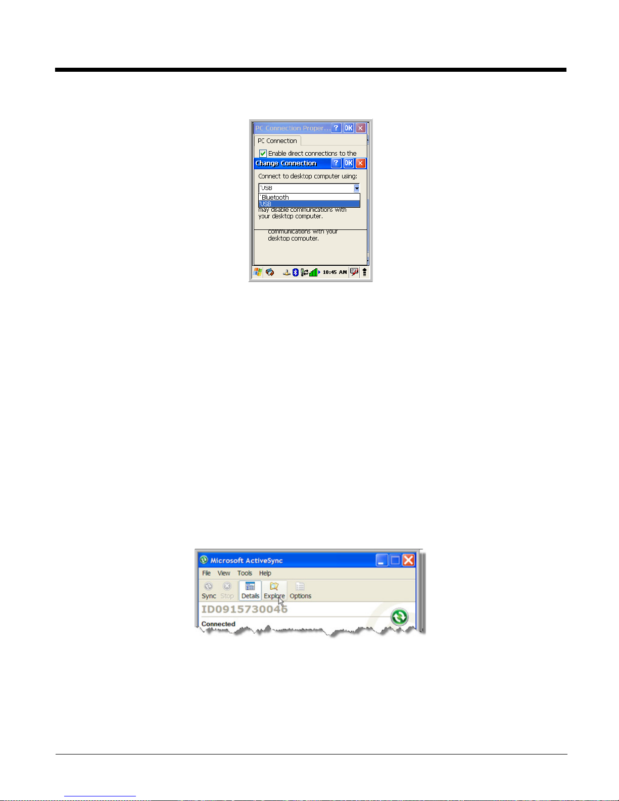
Tap Change Connection to change the current settings.
Connection Options Select this option to …
Bluetooth Establish an ActiveSync connection via Bluetooth.
This menu item is present only when Bluetooth has been activated.
‘USB Establish a USB connection.
Communicating with the Terminal
After setting up both the workstation and the terminal, ActiveSync connection should be automatic.
1. Connect the PM250 terminal to a communication peripheral, such as the PM250 Cradle.
2. The PM250 terminal automatically opens ActiveSync to establish a connection.
Synchronizing with the Host Workstation
After setup, synchronization begins automatically whenever the terminal’s mechanical connector
connects to a PM250 peripheral that is connected to a host workstation with ActiveSync installed.
Exploring the Terminal from the Workstation
When the terminal and desktop computer are connected, open the main ActiveSync window (on the
desktop), and click Explore.
Page 31
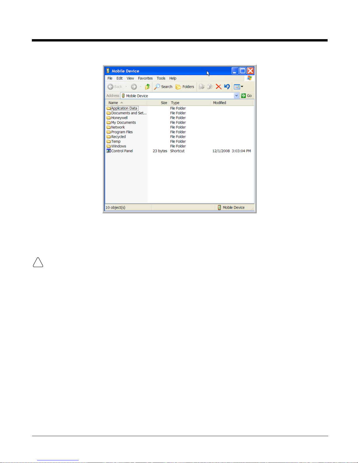
The Mobile Device folder opens in Windows Explorer.
!
The terminal is now treated as a mass storage device, and transferring files is as simple as
dragging and dropping or copying and pasting as you would for moving files between folders on your hard
drive.
Adding Programs via ActiveSync
When selecting programs, verify that the program and version of the program are designed for the Windows CE 5.0 and
the terminal’s processor. You can verify your processor by tapping Start > Settings > Control Panel > System > General
!
tab. Make a note of the information in the Processor field.
If the File is an Installer
An installer program is one that installs to the workstation and the terminal simultaneously; one process
installs to both devices.
1. On the workstation, double-click the *.exe or *.setup.exe file. The installation wizard begins.
2. Follow the directions on the workstation screen.
The installation process includes transferring the software to the terminal via ActiveSync.
Page 32

If the File is Not an Installer
Some programs cannot be installed on workstations because they are designed exclusively for Windows
CE devices. In these cases, the appropriate files must be stored on the host workstation and transferred
to the terminal via ActiveSync Explore.
Note: You know that the program is not an installer because an error message stating that the program is valid but
designed for a different type of computer appears when you try to install the program on the
1. If you cannot find any installation instructions for the program in the Read Me file or documentation,
open ActiveSync on the workstation and click Explore.
2. On the workstation, navigate to the workstation folder containing the program file(s) and copy them
to the Program Files folder on the terminal.
3. On the terminal Desktop, tap My Device and, in Windows Explorer, navigate to the folder where the
program is located.
4. Double tap on the program file to install it.
If you copied the file to the Autoinstall
hard reset. The program installs as part of initialization.
5. After installation is complete, access the program by tapping Start > Programs and the program
appears on the Programs screen. Tap the icon to open the program.
folder, you can choose to install the program by performing a
workstation
.
Wireless Radios
There are two radio options: 802.11b/g and Bluetooth.
1. 802.11b/g (WPAN/WLAN configuration): see WLAN (802.11b/g Radio), below.
2. Bluetooth (WPAN configuration): see Bluetooth Manager.
Connecting the Terminal to a Wireless Network
You connect the terminal to a wireless network through the on-board radio (802.11b/g and/or Bluetooth).
Each radio has its own configuration program and requires specific information about the wireless
network to connect. Successful connection depends on your network infrastructure about which you will
need specific information from your network administrator.
WLAN (802.11b/g Radio)
250s can have a 2.4 GHz 802.11b/g WLAN (Wireless Local Area Network) radio that uses Direct
Sequence Spread Spectrum (DSSS) technology. The radio is interoperable with other 802.11b/g, Wi-Ficompliant products including access points (APs), workstations via PC card adapters, and other wireless
portable devices.
By default, the 802.11b/g radio is enabled after each hard reset, which means that the radio begins
transmitting a signal as soon as the terminal finishes booting up. The next step is to configure the
connection parameters of the radio to connect to a wireless network.
Page 33
5
&UDGOH Device
Overview
Note: The information in this chapter applies to both the Cradle devices
unless otherwise indicated.
Battery Charging
The base completes a full charge of the main battery pack in four hours for the standard capacity
2200mAh pack and six hours for the extended capacity 3300mAh pack.
In addition to charging, the base powers the intelligent battery charging system in the terminal that
protects the battery from being damaged by overcharging. The terminal senses when a battery pack is
fully charged and automatically switches to a trickle charge that maintains the battery at full capacity. As
a result, PM250 terminals may be stored in the base indefinitely without damage to the terminals, battery
packs, or peripherals.
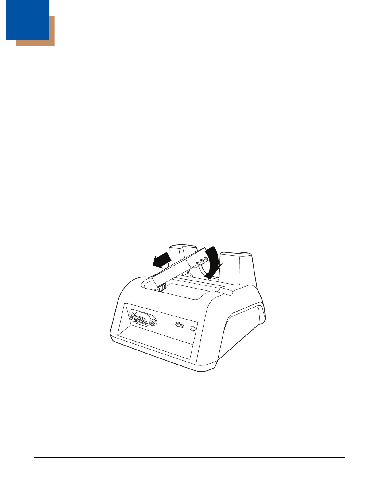
The base can also charge a second battery while the terminal is positioned in the base. The second
battery can be inserted in the battery charging well in back of the terminal connection. Place the battery
in the well with the label facing up and toward the back of the unit. Once the connectors engage, the LED
lights. If the LED is red, the unit is charging; if it is green, the charge is complete.
Communication
The base can communicate via USB . Data transmission for USB is up to 12 Mbps.
Page 34
Convenient Storage
The battery charging system makes the base a safe and convenient storage receptacle for your terminal.
Capacity
The base holds one 250 and charges its battery pack. It also charges a spare battery in the well behind
the terminal.
Power Supply
The power cable that ships with each terminal also powers the base.
We recommend use of PM250 peripherals, power cables, and power adapters. Use of any non- PM250
peripherals, cables, or power adapters may cause damage not covered by the warranty.
!
We recommend use of Li-Ion battery packs. Use of any non- our battery may result in
damage not covered by the warranty. DO NOT attempt to charge damp/wet mobile computers or batteries.
!
All components must be dry before connecting to an external power source.
Front Panel
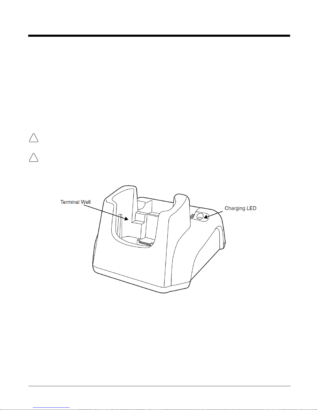
Terminal Well
Place the PM250 terminal in this well to communicate with a host device, power the terminal,
and charge its battery. Make sure that the device is securely seated.
Rubber Feet
The bottom panel has four rubber feet to stabilize the unit on a flat surface. You can set the
base on a dry, stable surface, such as a desktop or workbench near an electrical outlet.
Page 35
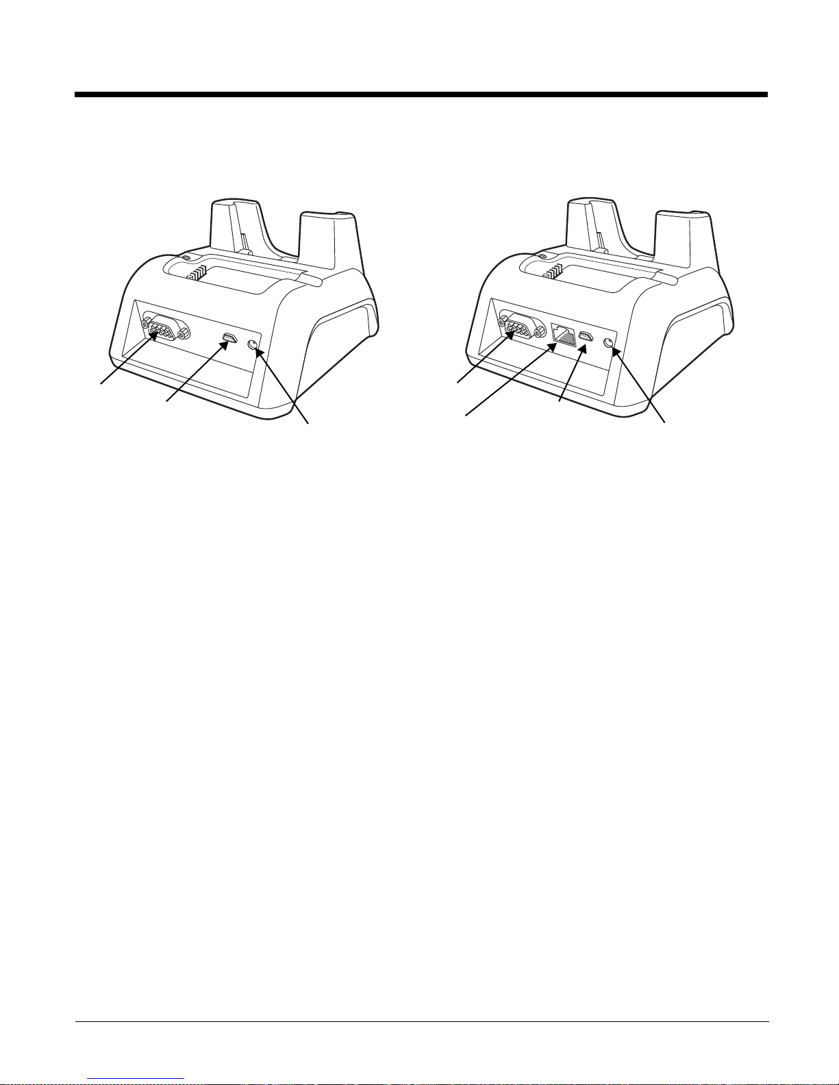
Back Panel
DC Power Jack
Connect the power cable to this power jack
USB Port
The USB port is full-speed (v1.1). Using the USB cable, you can connect the base to a USBcompliant device to facilitate USB communication to and from the terminal. USB
communication occurs through Microsoft ActiveSync (v.4.1 or higher).
Serial Port
The serial port supports serial communication between the terminal and another device. Note
that the connector is a DB9 Male connector, requiring a female connector on the serial cable.
The following four signals are supported:
• Transmitted Data
• Received Data
• Request to Send
• Clear to Send
Note: ActiveSync is not supported over the serial port.
Page 36
Powering the 30 Device
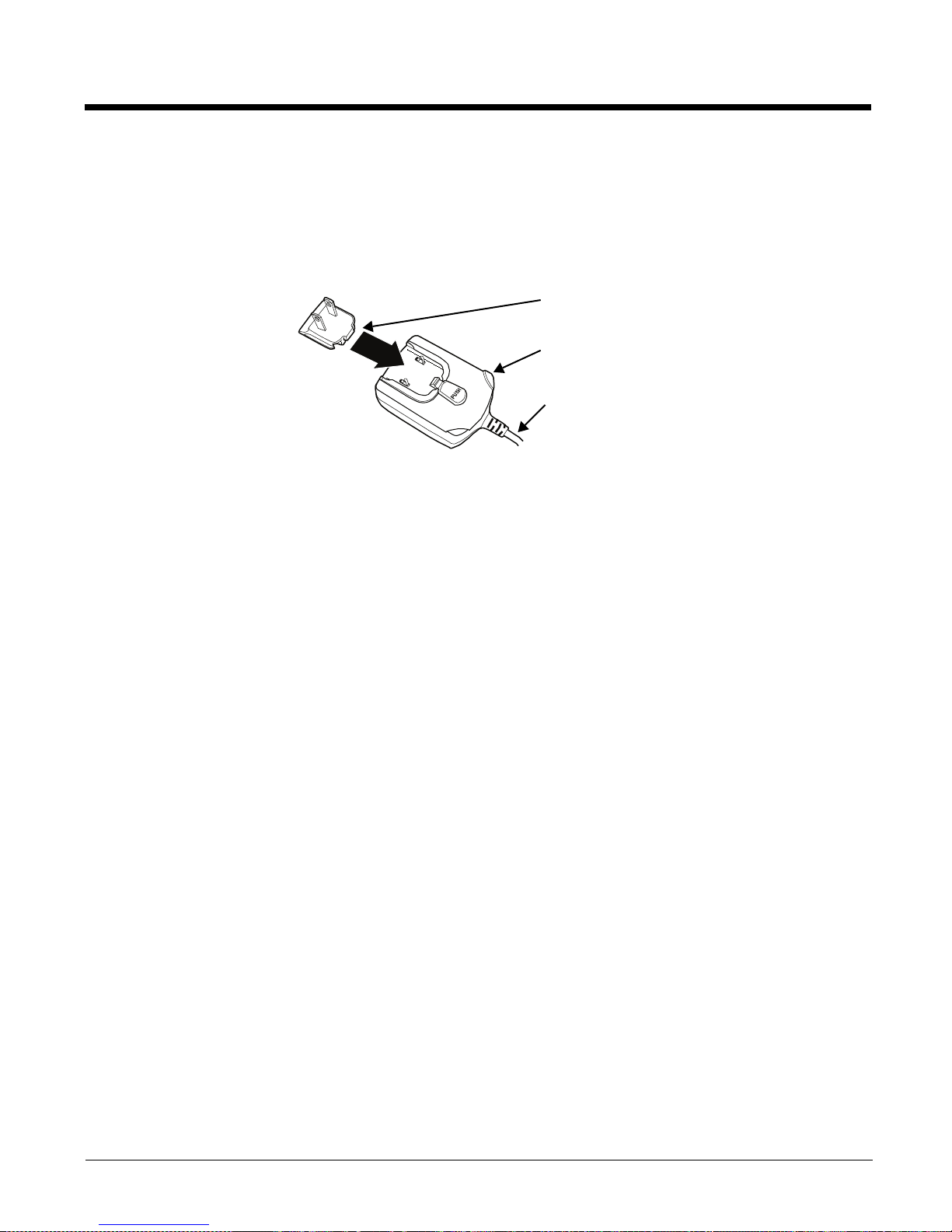
The terminal requires 5 volts DC input for communication and battery charging; the power adapter on the
power cable converts the voltage from the power source to 5 volts DC. Only power adapter cables from
convert the voltage appropriately.
The same power cable that ships with each terminal can be used to power the base. This cable contains
a plug adapter for each geography (US, UK, EU, etc.).
1. Attach the appropriate plug adapter to the power adapter.
2. Plug the power cable into the power source.
3. Plug the connector into the DC power jack on the back panel. The base is now powered.
When a terminal is properly seated, the base powers the terminal, charges the terminal’s main battery
pack, and launches ActiveSync
Plug Adapter
Power Adapter
Power Cable
Page 37
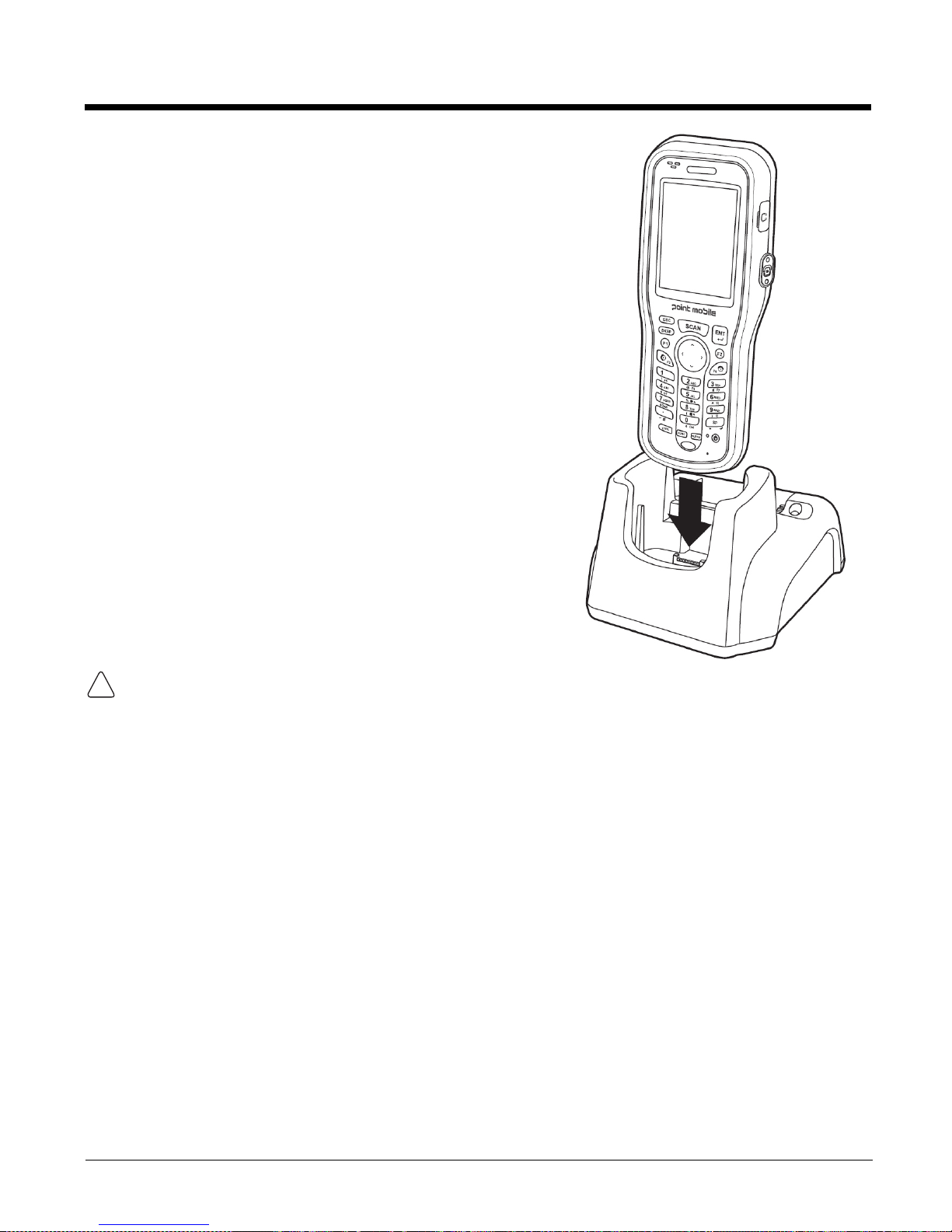
Charging the Main Battery
The base powers the terminal and fully charges its main
battery pack in 4 or 6 hours depending on the battery.
As battery packs charge, the charging circuitry follows the twostep charging process (CC-CV) that is recommended for Li-Ion
batteries. The process monitors changes in temperature,
current, and voltage.
Inserting a Terminal
1. Install the battery pack in the terminal; see Install the
Main Battery
2. Power the base
3. Slide the terminal into the terminal well making certain
that the terminal is seated properly.
4. The battery pack begins charging.
Make sure the terminal is dry before placing it in the base.
!
Do NOT place a wet terminal in the base! Doing so may cause damage not covered by the warranty.
Page 38
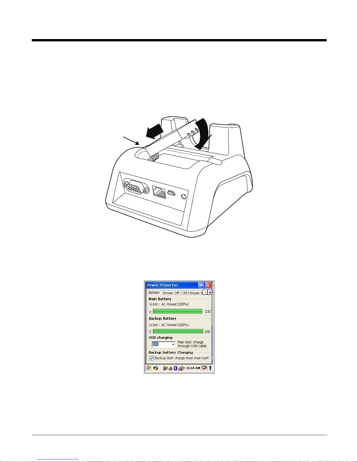
Charging a Spare Battery
Charging LED
The base can also charge a second battery while the terminal is positioned in the base. The second
battery can be inserted in the battery charging well in back of the terminal connection. Place the battery
in the well with the label facing up and toward the back of the unit. Angle the battery as shown. Once the
connectors engage, the LED lights. If the LED is red, the unit is charging; if it is green, the charge is
complete.
Checking Battery Power
To check battery power while the terminal is operating, tap Start > Settings > Control Panel > double
tap Power.
Page 39
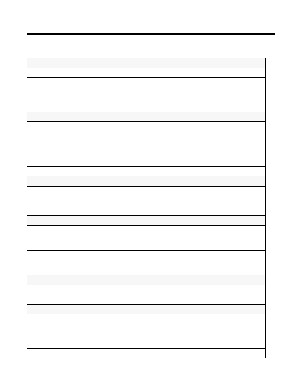
Technical Specifications
Structural
Dimensions 5.3 in. high X 4.5 in. wide X 3.1 in. deep (13.5 cm. X 11.4 cm. X 7.9 cm.)
Weight&UDGOH - 11.0 oz. (313g)
Material Polycarbonate
Color Black
Environmental
Operating Temperature 32° to 104°F (0° to 40°C)
Storage Temperature -4° to 140°F (-20° to +60°C)
Charging Temperature 32° to 104°F (0° to 40°C)
Electrical Static Discharge Air: ± 15k Vdc
Direct: ± 8k Vdc
Humidity 90% relative humidity (non-condensing)
Power Supply
Input (Universal)
(from the power source)
Output (to the base) 5 Volts DC, 2.0 A
Charging
Standard Charge
Max Charging Current 2A Max
Standby Current <100mA
Status LED Green: charged
Communication
Interface USB Mini-B Male connector supports data transmission of up to12 Mbps
Agency Approvals
Power Supply: UL listed
100–240 Volts, 0.3 A
50–60Hz
Included with terminal
Standard Capacity: 2200mAh - four hours
Extended Capacity: 3300mAh - six hours
Red: charging
OR
Standard DB9 serial connector supports data transmission up to 115 Kbps
TUV licensed
Power Supply compliant to FCC part 15, Class B
Charging: CE Marking (EMC)
CISPR Pub 22
Fire Retardant: UL 94-VO
 Loading...