

Page 1

Pointmaker®PVI-65
HD/SD-SDI Broadcast Video Marker
User’s Manual
Page 2

Page 3

Pointmaker® PVI™-65
HD/SD-SDI Broadcast Video Marker
User’s Manual
Page 4

Copyright
© 2005 by Boeckeler Instruments, Inc.,
4650 S. Butterfield Drive, Tucson, AZ 85714; (520)745-0001
No part of this publication may be reproduced, transmitted, transcribed, stored in a retrieval
system or translated into any language in any form by any means without the expressed written
permission of Boeckeler Instruments, Inc.
®
Pointmaker® and Boeckeler
are registered trademarks of Boeckeler Instruments, Inc., of
Tucson, Arizona. All other trademarks and registered trademarks are the property of their
respective companies.
P/N 040405
Page 5

Contents
CONTENTS
SECTION ONE:
GETTING STARTED . . . . . . . . . . . . . . . . . . . . . . . . . . . . . . . . . . . . . . . . . . . . . . . . . . 1
Introduction. . . . . . . . . . . . . . . . . . . . . . . . . . . . . . . . . . . . . . . . . . . . . . . . . . . . . . . . . . . . . . . . . . . . 3
A Professional Marker for HD/SD-SDI . . . . . . . . . . . . . . . . . . . . . . . . . . . . . . . . . . . . . . . . . . . . 3
Features . . . . . . . . . . . . . . . . . . . . . . . . . . . . . . . . . . . . . . . . . . . . . . . . . . . . . . . . . . . . . . . . . . . . . . . 7
Peripheral Devices . . . . . . . . . . . . . . . . . . . . . . . . . . . . . . . . . . . . . . . . . . . . . . . . . . . . . . . . . . . . . . 9
Digitizing Tablet. . . . . . . . . . . . . . . . . . . . . . . . . . . . . . . . . . . . . . . . . . . . . . . . . . . . . . . . . . . . . 10
Keyboard Controller. . . . . . . . . . . . . . . . . . . . . . . . . . . . . . . . . . . . . . . . . . . . . . . . . . . . . . . . . . 13
Touch Screen . . . . . . . . . . . . . . . . . . . . . . . . . . . . . . . . . . . . . . . . . . . . . . . . . . . . . . . . . . . . . . . 16
Mouse-type Devices . . . . . . . . . . . . . . . . . . . . . . . . . . . . . . . . . . . . . . . . . . . . . . . . . . . . . . . . . . 18
Installation. . . . . . . . . . . . . . . . . . . . . . . . . . . . . . . . . . . . . . . . . . . . . . . . . . . . . . . . . . . . . . . . . . . . 21
Connecting Video Source and Output(s) . . . . . . . . . . . . . . . . . . . . . . . . . . . . . . . . . . . . . . . . . . 21
Connecting Control Devices. . . . . . . . . . . . . . . . . . . . . . . . . . . . . . . . . . . . . . . . . . . . . . . . . . . . 21
Activation. . . . . . . . . . . . . . . . . . . . . . . . . . . . . . . . . . . . . . . . . . . . . . . . . . . . . . . . . . . . . . . . . . . . . 25
Power Up . . . . . . . . . . . . . . . . . . . . . . . . . . . . . . . . . . . . . . . . . . . . . . . . . . . . . . . . . . . . . . . . . . 25
Menu Basics . . . . . . . . . . . . . . . . . . . . . . . . . . . . . . . . . . . . . . . . . . . . . . . . . . . . . . . . . . . . . . . . 25
Built-in Help Messages. . . . . . . . . . . . . . . . . . . . . . . . . . . . . . . . . . . . . . . . . . . . . . . . . . . . . . . . 27
SECTION TWO:
ANNOTATION MENU . . . . . . . . . . . . . . . . . . . . . . . . . . . . . . . . . . . . . . . . . . . . . . . . 29
Annotation Settings . . . . . . . . . . . . . . . . . . . . . . . . . . . . . . . . . . . . . . . . . . . . . . . . . . . . . . . . . . . . 31
Pointers . . . . . . . . . . . . . . . . . . . . . . . . . . . . . . . . . . . . . . . . . . . . . . . . . . . . . . . . . . . . . . . . . . . . 31
Selecting an Erase Method . . . . . . . . . . . . . . . . . . . . . . . . . . . . . . . . . . . . . . . . . . . . . . . . . . . . . 32
Selecting a Line Style . . . . . . . . . . . . . . . . . . . . . . . . . . . . . . . . . . . . . . . . . . . . . . . . . . . . . . . . . 33
Customizing the Color Palette . . . . . . . . . . . . . . . . . . . . . . . . . . . . . . . . . . . . . . . . . . . . . . . . . . 34
Setting an Overlay Brightness Level . . . . . . . . . . . . . . . . . . . . . . . . . . . . . . . . . . . . . . . . . . . . . 36
Changing Pen Proximity. . . . . . . . . . . . . . . . . . . . . . . . . . . . . . . . . . . . . . . . . . . . . . . . . . . . . . . 38
Pointer Toggle. . . . . . . . . . . . . . . . . . . . . . . . . . . . . . . . . . . . . . . . . . . . . . . . . . . . . . . . . . . . . . . 38
SECTION THREE:
DISPLAY MENU . . . . . . . . . . . . . . . . . . . . . . . . . . . . . . . . . . . . . . . . . . . . . . . . . . . . 41
The Display Menu. . . . . . . . . . . . . . . . . . . . . . . . . . . . . . . . . . . . . . . . . . . . . . . . . . . . . . . . . . . . . . 43
Programming Video Mode . . . . . . . . . . . . . . . . . . . . . . . . . . . . . . . . . . . . . . . . . . . . . . . . . . . . . 43
Boeckeler Instruments, Inc. Pointmaker PVI-65 HD/SD-SDI Broadcast Video Marker - Page i
Page 6

Contents
Turning Zap Icon On/Off. . . . . . . . . . . . . . . . . . . . . . . . . . . . . . . . . . . . . . . . . . . . . . . . . . . . . . 44
Turning Touch Screen Function Areas On/Off . . . . . . . . . . . . . . . . . . . . . . . . . . . . . . . . . . . . . 45
SECTION FOUR:
COMM PORT DEVICES MENU. . . . . . . . . . . . . . . . . . . . . . . . . . . . . . . . . . . . . . . . . 47
Comm Port Operations . . . . . . . . . . . . . . . . . . . . . . . . . . . . . . . . . . . . . . . . . . . . . . . . . . . . . . . . . 49
Controllers Requiring Calibration . . . . . . . . . . . . . . . . . . . . . . . . . . . . . . . . . . . . . . . . . . . . . . . 49
Serial Port Settings. . . . . . . . . . . . . . . . . . . . . . . . . . . . . . . . . . . . . . . . . . . . . . . . . . . . . . . . . . . 53
SECTION FIVE:
USING MARKERS. . . . . . . . . . . . . . . . . . . . . . . . . . . . . . . . . . . . . . . . . . . . . . . . . . . 59
Overview . . . . . . . . . . . . . . . . . . . . . . . . . . . . . . . . . . . . . . . . . . . . . . . . . . . . . . . . . . . . . . . . . . . . . 61
Basic Marking Concepts . . . . . . . . . . . . . . . . . . . . . . . . . . . . . . . . . . . . . . . . . . . . . . . . . . . . . . 61
Assigning Marker Appearance. . . . . . . . . . . . . . . . . . . . . . . . . . . . . . . . . . . . . . . . . . . . . . . . . . . 63
Assigning Marker Colors. . . . . . . . . . . . . . . . . . . . . . . . . . . . . . . . . . . . . . . . . . . . . . . . . . . . . . 63
Assigning Line Styles. . . . . . . . . . . . . . . . . . . . . . . . . . . . . . . . . . . . . . . . . . . . . . . . . . . . . . . . . 64
Selecting Pointers. . . . . . . . . . . . . . . . . . . . . . . . . . . . . . . . . . . . . . . . . . . . . . . . . . . . . . . . . . . . 65
Turning the Active Pointer On/Off . . . . . . . . . . . . . . . . . . . . . . . . . . . . . . . . . . . . . . . . . . . . . . 65
Marking. . . . . . . . . . . . . . . . . . . . . . . . . . . . . . . . . . . . . . . . . . . . . . . . . . . . . . . . . . . . . . . . . . . . . . 67
Entering the Marking Mode. . . . . . . . . . . . . . . . . . . . . . . . . . . . . . . . . . . . . . . . . . . . . . . . . . . . 67
Pointing . . . . . . . . . . . . . . . . . . . . . . . . . . . . . . . . . . . . . . . . . . . . . . . . . . . . . . . . . . . . . . . . . . . 67
Drawing . . . . . . . . . . . . . . . . . . . . . . . . . . . . . . . . . . . . . . . . . . . . . . . . . . . . . . . . . . . . . . . . . . . 68
Typing Text Labels . . . . . . . . . . . . . . . . . . . . . . . . . . . . . . . . . . . . . . . . . . . . . . . . . . . . . . . . . . 69
Sizing and Anchoring Frames . . . . . . . . . . . . . . . . . . . . . . . . . . . . . . . . . . . . . . . . . . . . . . . . . . 70
Stamping the Date/Time. . . . . . . . . . . . . . . . . . . . . . . . . . . . . . . . . . . . . . . . . . . . . . . . . . . . . . . 71
Clearing Markers. . . . . . . . . . . . . . . . . . . . . . . . . . . . . . . . . . . . . . . . . . . . . . . . . . . . . . . . . . . . . . 75
Clearing All Markers . . . . . . . . . . . . . . . . . . . . . . . . . . . . . . . . . . . . . . . . . . . . . . . . . . . . . . . . . 75
Undoing a Marker . . . . . . . . . . . . . . . . . . . . . . . . . . . . . . . . . . . . . . . . . . . . . . . . . . . . . . . . . . . 75
Erasing Markers . . . . . . . . . . . . . . . . . . . . . . . . . . . . . . . . . . . . . . . . . . . . . . . . . . . . . . . . . . . . . 76
Manipulating Overlays . . . . . . . . . . . . . . . . . . . . . . . . . . . . . . . . . . . . . . . . . . . . . . . . . . . . . . . . . 79
Paging Through Overlays. . . . . . . . . . . . . . . . . . . . . . . . . . . . . . . . . . . . . . . . . . . . . . . . . . . . . . 79
Turning Off the Marker Overlay . . . . . . . . . . . . . . . . . . . . . . . . . . . . . . . . . . . . . . . . . . . . . . . . 80
SECTION SIX:
COMMANDS FOR RS-232 CONTROL. . . . . . . . . . . . . . . . . . . . . . . . . . . . . . . . . . . . 81
Introduction . . . . . . . . . . . . . . . . . . . . . . . . . . . . . . . . . . . . . . . . . . . . . . . . . . . . . . . . . . . . . . . . . . 83
Page ii - Pointmaker PVI-65 HD/SD-SDI Broadcast Video Marker Boeckeler Instruments, Inc.
Page 7

Contents
X-Y Coordinate Grid . . . . . . . . . . . . . . . . . . . . . . . . . . . . . . . . . . . . . . . . . . . . . . . . . . . . . . . . . 83
Commands. . . . . . . . . . . . . . . . . . . . . . . . . . . . . . . . . . . . . . . . . . . . . . . . . . . . . . . . . . . . . . . . . . . . 85
(C) Active Marker Off/On . . . . . . . . . . . . . . . . . . . . . . . . . . . . . . . . . . . . . . . . . . . . . . . . . . . . . 85
(CE) Color Enable. . . . . . . . . . . . . . . . . . . . . . . . . . . . . . . . . . . . . . . . . . . . . . . . . . . . . . . . . . . . 85
(CL) Clear. . . . . . . . . . . . . . . . . . . . . . . . . . . . . . . . . . . . . . . . . . . . . . . . . . . . . . . . . . . . . . . . . . 86
(CM) Marker Move. . . . . . . . . . . . . . . . . . . . . . . . . . . . . . . . . . . . . . . . . . . . . . . . . . . . . . . . . . . 86
(CS) Color Selection. . . . . . . . . . . . . . . . . . . . . . . . . . . . . . . . . . . . . . . . . . . . . . . . . . . . . . . . . . 86
(DL) Draw Line . . . . . . . . . . . . . . . . . . . . . . . . . . . . . . . . . . . . . . . . . . . . . . . . . . . . . . . . . . . . . 87
(DP) Drop Marker. . . . . . . . . . . . . . . . . . . . . . . . . . . . . . . . . . . . . . . . . . . . . . . . . . . . . . . . . . . . 87
(E) Echo . . . . . . . . . . . . . . . . . . . . . . . . . . . . . . . . . . . . . . . . . . . . . . . . . . . . . . . . . . . . . . . . . . . 87
(EM) Erase Method. . . . . . . . . . . . . . . . . . . . . . . . . . . . . . . . . . . . . . . . . . . . . . . . . . . . . . . . . . . 88
(FS) Frame Size . . . . . . . . . . . . . . . . . . . . . . . . . . . . . . . . . . . . . . . . . . . . . . . . . . . . . . . . . . . . . 88
(FT) Frame Type. . . . . . . . . . . . . . . . . . . . . . . . . . . . . . . . . . . . . . . . . . . . . . . . . . . . . . . . . . . . . 88
(I) Marker Intensity or Brightness . . . . . . . . . . . . . . . . . . . . . . . . . . . . . . . . . . . . . . . . . . . . . . . 88
(IM) Identify Mode for Multiple Users . . . . . . . . . . . . . . . . . . . . . . . . . . . . . . . . . . . . . . . . . . . 89
(L) Line Style . . . . . . . . . . . . . . . . . . . . . . . . . . . . . . . . . . . . . . . . . . . . . . . . . . . . . . . . . . . . . . . 89
(PA) Pass-through. . . . . . . . . . . . . . . . . . . . . . . . . . . . . . . . . . . . . . . . . . . . . . . . . . . . . . . . . . . . 89
(PT) Pointer Type . . . . . . . . . . . . . . . . . . . . . . . . . . . . . . . . . . . . . . . . . . . . . . . . . . . . . . . . . . . . 90
(PX) Proximity On/Off. . . . . . . . . . . . . . . . . . . . . . . . . . . . . . . . . . . . . . . . . . . . . . . . . . . . . . . . 90
(R) Restart Pointmaker . . . . . . . . . . . . . . . . . . . . . . . . . . . . . . . . . . . . . . . . . . . . . . . . . . . . . . . . 91
(S) Date/Time Marker. . . . . . . . . . . . . . . . . . . . . . . . . . . . . . . . . . . . . . . . . . . . . . . . . . . . . . . . . 91
(SU) Port Initialization . . . . . . . . . . . . . . . . . . . . . . . . . . . . . . . . . . . . . . . . . . . . . . . . . . . . . . . . 91
(SUM) Menu System . . . . . . . . . . . . . . . . . . . . . . . . . . . . . . . . . . . . . . . . . . . . . . . . . . . . . . . . . 92
(T) Text Label. . . . . . . . . . . . . . . . . . . . . . . . . . . . . . . . . . . . . . . . . . . . . . . . . . . . . . . . . . . . . . . 92
(TC) Touch Screen Corner Control . . . . . . . . . . . . . . . . . . . . . . . . . . . . . . . . . . . . . . . . . . . . . . 93
(U) Undo/Erase. . . . . . . . . . . . . . . . . . . . . . . . . . . . . . . . . . . . . . . . . . . . . . . . . . . . . . . . . . . . . . 93
(V) Select an Overlay . . . . . . . . . . . . . . . . . . . . . . . . . . . . . . . . . . . . . . . . . . . . . . . . . . . . . . . . . 93
(Z) Zap Icon . . . . . . . . . . . . . . . . . . . . . . . . . . . . . . . . . . . . . . . . . . . . . . . . . . . . . . . . . . . . . . . . 94
APPENDIX . . . . . . . . . . . . . . . . . . . . . . . . . . . . . . . . . . . . . . . . . . . . . . . . . . . . . . . . . A-1
Troubleshooting Guide. . . . . . . . . . . . . . . . . . . . . . . . . . . . . . . . . . . . . . . . . . . . . . . . . . . . . . . . . A-3
Quick Reference for Devices . . . . . . . . . . . . . . . . . . . . . . . . . . . . . . . . . . . . . . . . . . . . . . . . . . . . A-5
Quick Reference for Digitizing Tablet . . . . . . . . . . . . . . . . . . . . . . . . . . . . . . . . . . . . . . . . . . .A-5
Quick Reference for Keyboard. . . . . . . . . . . . . . . . . . . . . . . . . . . . . . . . . . . . . . . . . . . . . . . . . A-6
Quick Reference for Touch Screens and White Boards . . . . . . . . . . . . . . . . . . . . . . . . . . . . . . A-6
Boeckeler Instruments, Inc. Pointmaker PVI-65 HD/SD-SDI Broadcast Video Marker - Page iii
Page 8

Contents
Quick Reference for Other Mouse Devices. . . . . . . . . . . . . . . . . . . . . . . . . . . . . . . . . . . . . . . A-7
Glossary. . . . . . . . . . . . . . . . . . . . . . . . . . . . . . . . . . . . . . . . . . . . . . . . . . . . . . . . . . . . . . . . . . . . . A-9
Symbol Font Chart (keyboard) . . . . . . . . . . . . . . . . . . . . . . . . . . . . . . . . . . . . . . . . . . . . . . . . . A-13
Map Font Chart (keyboard). . . . . . . . . . . . . . . . . . . . . . . . . . . . . . . . . . . . . . . . . . . . . . . . . . . . A-15
RS-232 Pinout (COMM Port-male) . . . . . . . . . . . . . . . . . . . . . . . . . . . . . . . . . . . . . . . . . . . . . A-17
INDEX
Page iv - Pointmaker PVI-65 HD/SD-SDI Broadcast Video Marker Boeckeler Instrum ents, Inc.
Page 9

Page 10

Page 11

SECTION ONE: GETTING STARTED
Page 12

Page 13
Section One: Getting Started Introduction
INTRODUCTION
A Professional Marker for HD/SD-SDI
Powerful
The Pointmaker® PVI-65 HD/SD-SDI Broadcast Vi d eo Mark er by Boeckeler
Instruments, Inc., now makes it possible to utilize the power of video annotation with high definition video, using the Serial Digital Interface standard.
The PVI-65 can generate a key signal. This feature can be used by inputting
video and configuring SDI output #2 to pass the key signal. The key output is
routed to the broadcast switcher. The annotated video from SDI output #1 can
still be displayed on a preview monitor for talent or crew. These configurations
can be set through the Pointmaker menu system.
The HD/SD-SDI outputs can also be used to provide a key signal by inputting
a black reference signal, s etting annotation to white, and routing the signal to a
broadcast switcher.
In addition, it supports up to ten different pointing/marking/controlling devices
(digitizing tablet, touch screen, keyboard, mouse devices, etc.) for interacting
with the displayed images.
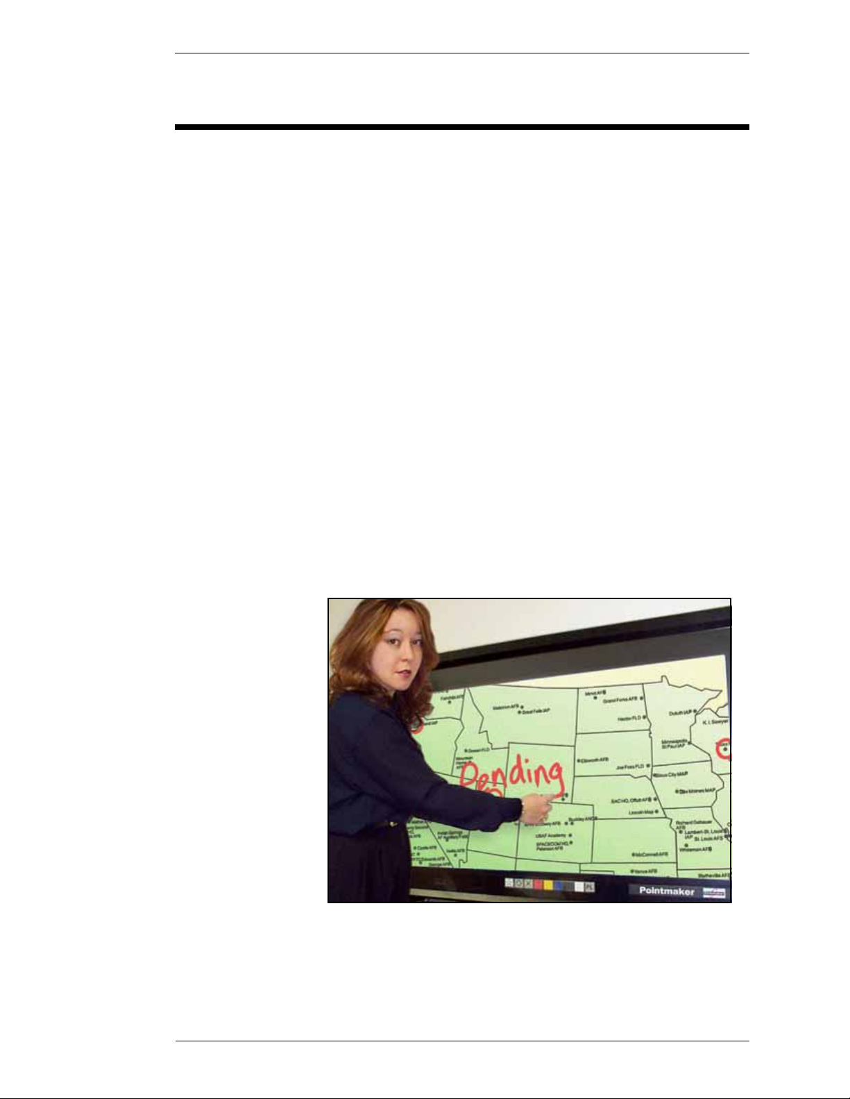
Figure 1-1: Marking on a plasma w/touch screen
Boeckeler Instruments, Inc. Pointmaker PVI-65 HD/SD-SDI Broadcast Video Marker - Page 3
Page 14
Introduction Section One: Getting Started
Effortless Interaction
This Pointmaker model can handle environments where a number of people
need to mark images during discussions or presentations. By giving each person a controller and having each mark in a unique color, it’s possible to
achieve a smooth coordination of discussion and marking among all participants.
Making Your Point
Marker Multiplicity
The large variety of Pointmaker markers further enhances your ability to
emphasize each point to an audience. To begin with, you can assign a variety
of colors to the markers you create. Marke r options include: varying line thicknesses (with or without drop shadows), text labels in multiple fonts and sizes,
arrows or pointers of dif fering shapes and s izes. None of the markers af fect the
original images in any way. Markers actually exist on a clear layer above the
image called an “overlay”.
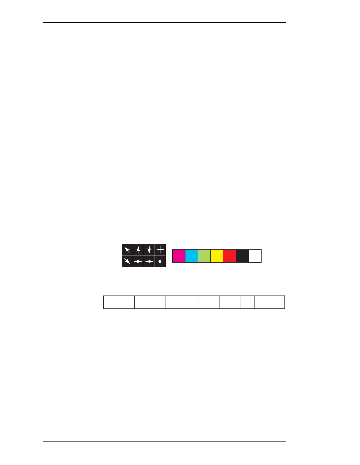
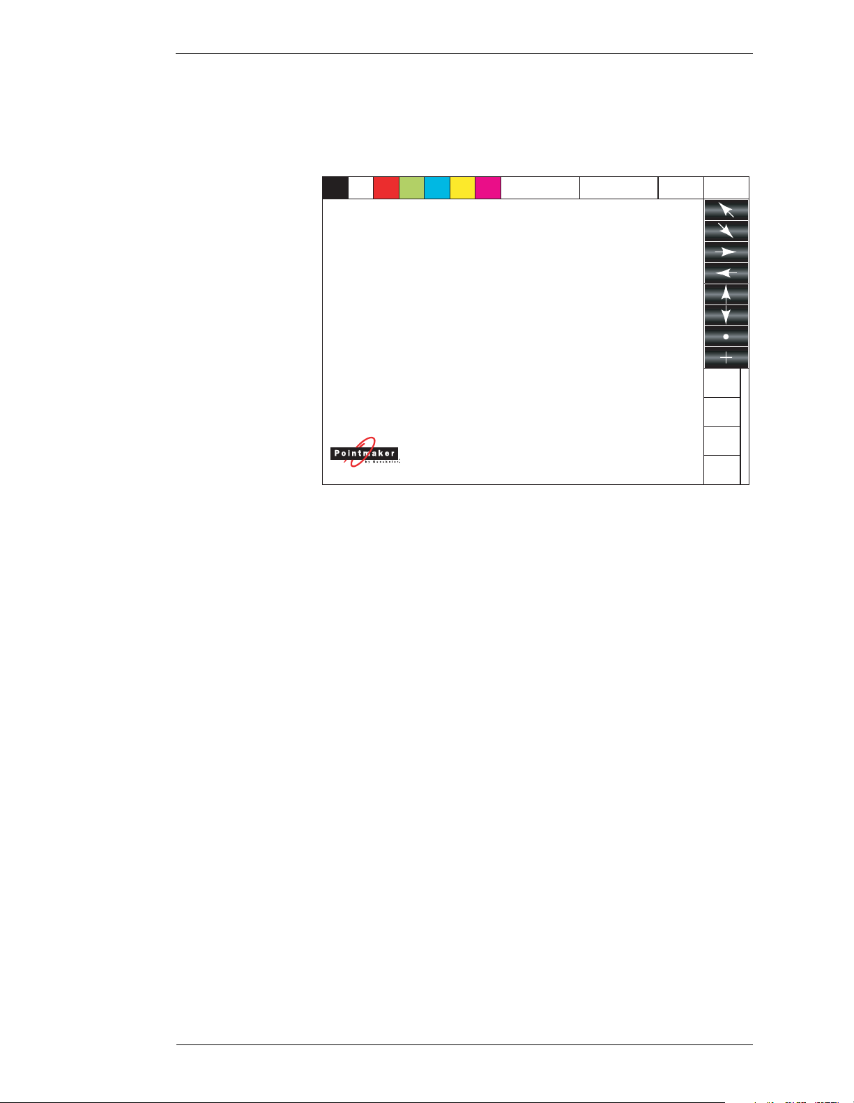
The figure below is a breakout of some digitizing tablet template commands,
illustrating some of the marker options. Each item is available at the click of a
button.
Hide / Show
Pointer
Pointer
On/Off
Pointers
Clear All
Markers HD/SD-SDI Video Out 2 Settings
Clear Undo/Erase
Figure 1-2: Breakout of PVI-65 Template Commands
Clear Last
Marker
or Erase
Marker Colors
Pass-throughKeyPreview Program
The keyboard controller supports some additional marker types: frames, a
date/time stamp, and straight line drawing. Frames include boxes and circles.
Frames can be sized in advance of a presentation, then used to frame or fill
certain areas of the video image.
Marker Manipulation
One of the most powerful features for presentations using a Pointmaker is the
ability to store up to 25 different marker overlays. They can be created and
saved ahead of time, ready for quick recall during the presentation. For more
Page 4 - Pointmaker PVI-65 HD/SD-SDI Broadcast Video Marker Boeckeler Instruments, Inc.
Page 15
Section One: Getting Started Introduction
on overlays, see “Basic Marki ng Concepts “ in “Section Five: Using Markers”
on page 61, and “Man i pulating Overlays” on page 79.
As easily as the markers are created, so are they easily erased: either one at a
time until the screen is clear, or all at once.
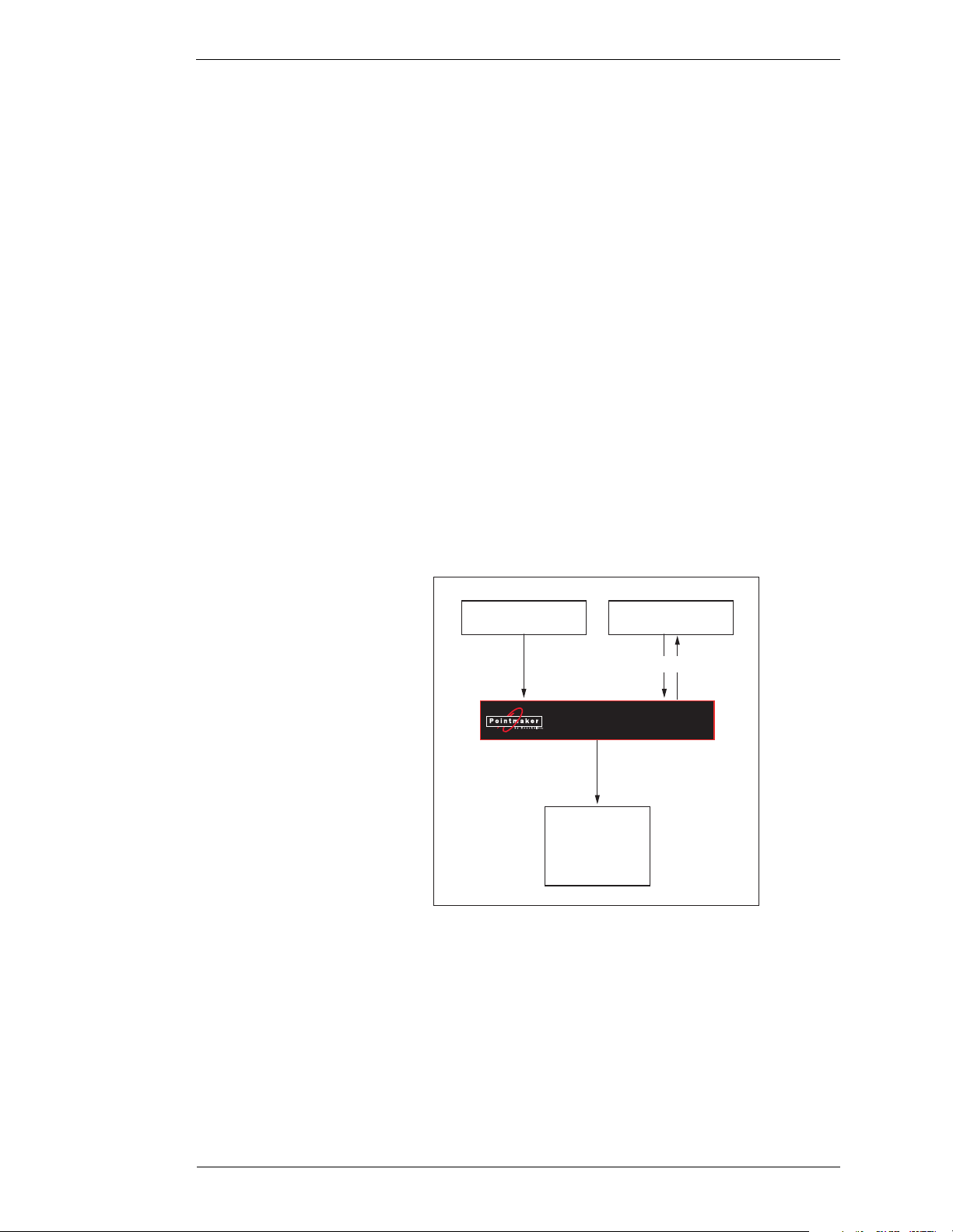
Ins and Outs
Connection Overview
You can think of the component connections as falling into three groups:
• The video source, which will supply the Pointmaker with the
images you want to mark over.
• The control devices, which allow you to select and manipulate the
markers. They also allow you to assign various display settings
within the Pointmaker.
• The displays, used to view the final output, such as monitors, projectors, big screens, LCD panels, etc.
Video Source
HD/SD - SDI Marker
Display(s)
Figure 1-3: PVI-65 Flow Di agram
Controller(s)
via USB/RS-232
PVI-65
Boeckeler Instruments, Inc. Pointmaker PVI-65 HD/SD-SDI Broadcast Video Marker - Page 5
Page 16

Introduction Section One: Getting Started
Page 6 - Pointmaker PVI-65 HD/SD-SDI Broadcast Video Marker Boeckeler Instruments, Inc.
Page 17

Section One: Getting Started Features
FEATURES
• HD/SD - SDI Compatibility
up to 1920x1080i, 720p.
• Multiple Controllers
Inputs for up to 10 pointing/marking/controlling devices.
• Two types of marking tools
Freehand drawing tools in six different line options; fine, medium
and bold, with or without a drop shadow.
Pointers, including arrows, dots and cross hairs, which may be
moved or anc hored anywhere on the screen. Arr ows may be preset to
point in one of 8 different angles. Dots and cross hairs may be preselected in a small or large size.
• Four additional marking tools with keyboard connected
Straight line drawing mode allows underscoring, mapping or other-
wise drawing a straight line. Three different line thicknesses are
available: fine, medium and bold, with or without a drop shadow.
Text can be typed on the video image in one of 6 different fonts, each
available in one or more sizes. You can add a text background to further enhance the text on the video image.
Frames in the shapes of circles or box es may be sized and positioned
to call attention to an area within the frame. Filled frames allo w you
to block out portions of the video image, useful in classroom exams
or in blocking out extraneous visuals.
An active date/time label can be placed on the video image to time
an event.
• The ability to position and anchor a combination of several markers
and drawings on the screen at once.
• Options for clearing lines and pointers from an overlay all at once,
one at a time (beginning with the most recently anchored marker), or
selectively erased.
• Ability to attribute a different color to each marker on the screen. Up
to 7 different colors are available for quick access. The color palette
can be minimized by presetting selections in a palett e menu.
• A drop shadow effect may be selected to further optimize the display
of drawn lines.
Boeckeler Instruments, Inc. Pointmaker PVI-65 HD/SD-SDI Broadcast Video Marker - Page 7
Page 18

Features Section One: Getting Started
• The ability to store up to 25 different marker overlays of Pointmaker
markers so that presentations may be prepared in advance. You can
scroll forward or backward a page at a time or enter an overlay number to quickly display the desired overlay using the keyboard or RS232 commands.
• Keyboard control provides you a quick way to select many of the
menu options without having to go to the menu system. Instead, function keys provide choices for pointer type, background, marker colors, brightness levels, on-screen help, video source selection and
more.
• Pen Proximity feature allows you to determine visibility of the active
pointer as the pen is moved away from the tablet or screen. The
pointer can be made to disappear as the pen is pu lled away, or to
remain on the video image, ready for positioning
• Brightness adjustment gives you the opportunity to set the brightness
of the Pointmaker markers to coincide with the brightness level of the
video signal, so that the ma rkers ar e displayed optimally fo r standard
video or for professional broadcasting.
• On-Screen Help to assist you in quickly setting up your presentations.
Page 8 - Pointmaker PVI-65 HD/SD-SDI Broadcast Video Marker Boeckeler Instruments, Inc.
Page 19

Section One: Getting Started Peripheral Devices
PERIPHERAL DEVICES
The peripherals for the Pointmaker fall easily into two categories:
• Displays - SD-SDI or HD-SDI compatible displays
• Controllers - Digitizing Tablets, Keyboards, Touch Screens,
Mouse Devices (USB or RS-232)
We offer a number of control devices for use with the Pointmaker PVI-65.
Some are included with certain models and some are sold separately . This section describes the basic opera tion of the most comm only us ed control lers. The
ones described are RS-232 devices but the PVI-65 also supports USB de vices.
A complete list of commands for these controllers are found in “Quick Reference for Devices“ in the “Appendix” on page A-5.
Boeckeler Instruments, Inc. Pointmaker PVI-65 HD/SD-SDI Broadcast Video Marker - Page 9
Page 20
Peripheral Devices Section One: Getting Started
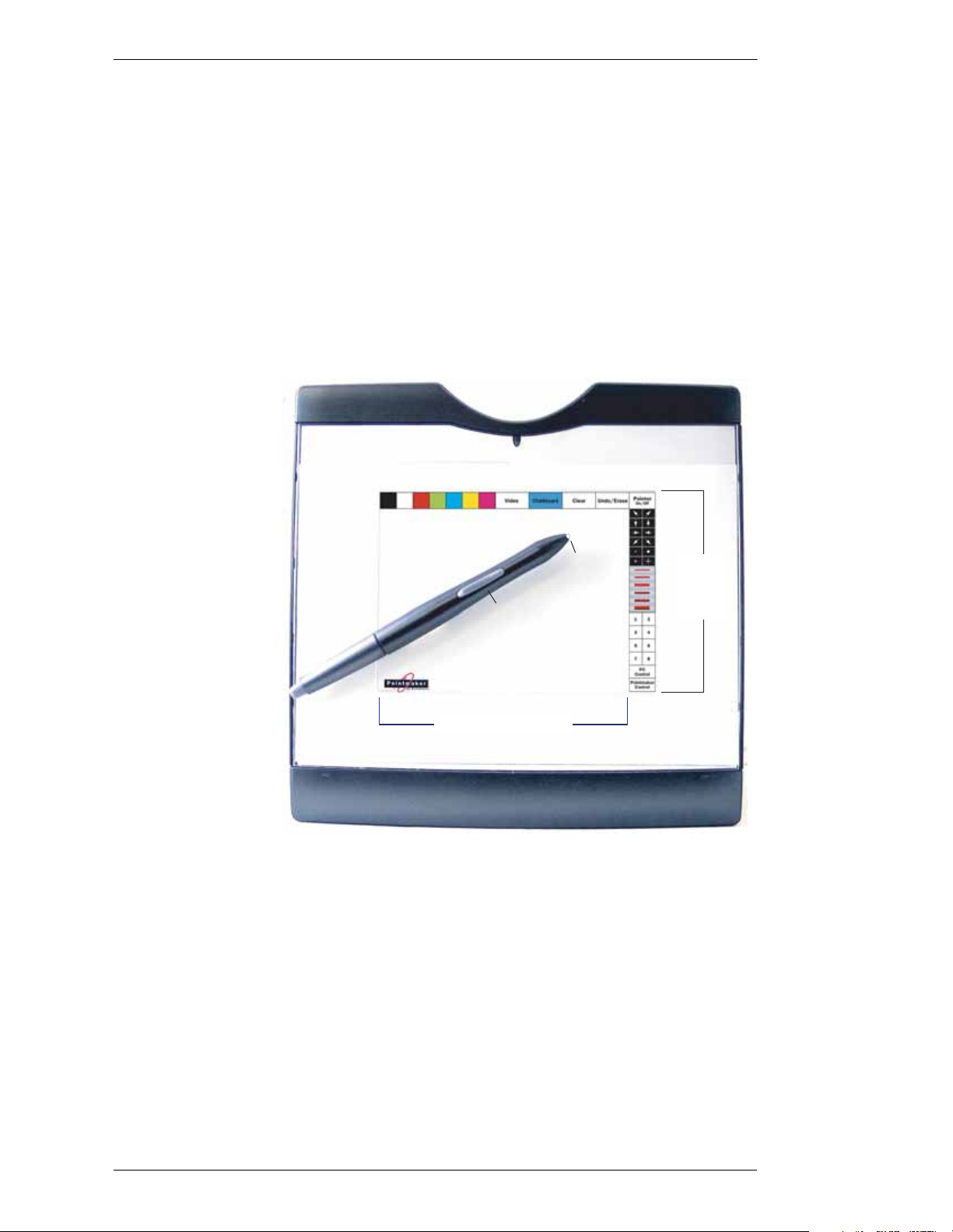
Digitizing Tablet
The Pointmaker Digitizing Tablet, similar to the one diagrammed below,
comes standard with the PVI-65. In general, the tablet is used to draw, position
pointers or make menu selections. The position and movements of the stylus
(also called a pen) are represented on whatever display devices are activated.
Additional ly, most setup commands ca n be activated using the tablet rather
than entering the menu system (See “Menu Basics” on page 25).
Refer back to this section, if needed, for general instructions concerning the
tablet’s operation.
Command Icons
Stylus / Pen
ACTIVE AREA
Tip
Button
Active
Area
Barrel
Toggle Switch
Tracking Area
Figure 1-4: Digitizing Tablet Overview
This is the area on the tablet that responds to the stylus. The template is placed here. This area measures 5" x 5" and includes the
Command Area and the Tracking Area.
RACKING AREA
T
This is the region within the tablet's Active Area that responds to
the stylus movements. The Tracking Area corresponds to the
Page 10 - Pointmaker PVI-65 HD/SD-SDI Broadcast Video Marker Boeckeler Instruments, Inc.
Page 21
Section One: Getting Started Peripheral Devices
screen area on the monitor or display. Pointmaker users draw and
point with the stylus in the Tracking Area.
PVI-65
COMMAND AREA
This is the top portion of the Active Area where Pointmaker
commands can be activated. The PVI-65 Template has image
icons or wor ds wh ich s tand f or PVI-65 comman ds an d allow you
to easily activate pointers, colors, and numerous other Pointmaker features.
Clear
Undo
Figure 1-5: Sample Template for PVI-65
Proximity
On/Off
Pointer
On/Off
Preview
Program
Key
Pass-
through
HD/SD-SDI OUT 2
IP BUTTON
T
When pressed (clicked) on a Menu Strip icon, the Tip Button
activates the function you select. When the Tip B utton is pressed
anywhere on the Tr acking Area and dragged, pointing or drawing takes place.
ARREL BUTTONS
B
When clicked, this button anchors the active pointer, if a pointer
is displayed.
OTH BUTTONS
B
The Tip Button is used in combination with the Barrel Button to
access the menu system where you can make selections not
available from the tablet template. The menu is activated by
pressing and holding the barrel button, while pressing the tip of
Boeckeler Instruments, Inc. Pointmaker PVI-65 HD/SD-SDI Broadcast Video Marker - Page 11
Page 22

Peripheral Devices Section One: Getting Started
the stylus into the drawing area for about five seconds. This feature is disabled if the keyboard is connected.
Marker and Cursor Movement
Unlike a mouse controller, a tablet allows users to make drawings and place
pointers with absolute positioning. Absolute positioning means that the position of the stylus on the tablet surface corresponds directly to the position of
the pointer on the screen. For e x ample, if you place the s tylus in th e lower-left
corner of the tablet active area, the active pointer will “jump” to the lower-left
corner of the screen.
A complete list of commands for this controller is found in “Quick Reference
for Devices“ in the “Appendix” on page A-5. Marking is describ ed in “Secti on
Five: Using Markers” starting on page 59.
Page 12 - Pointmaker PVI-65 HD/SD-SDI Broadcast Video Marker Boeckeler Instruments, Inc.
Page 23
Section One: Getting Started Peripheral Devices
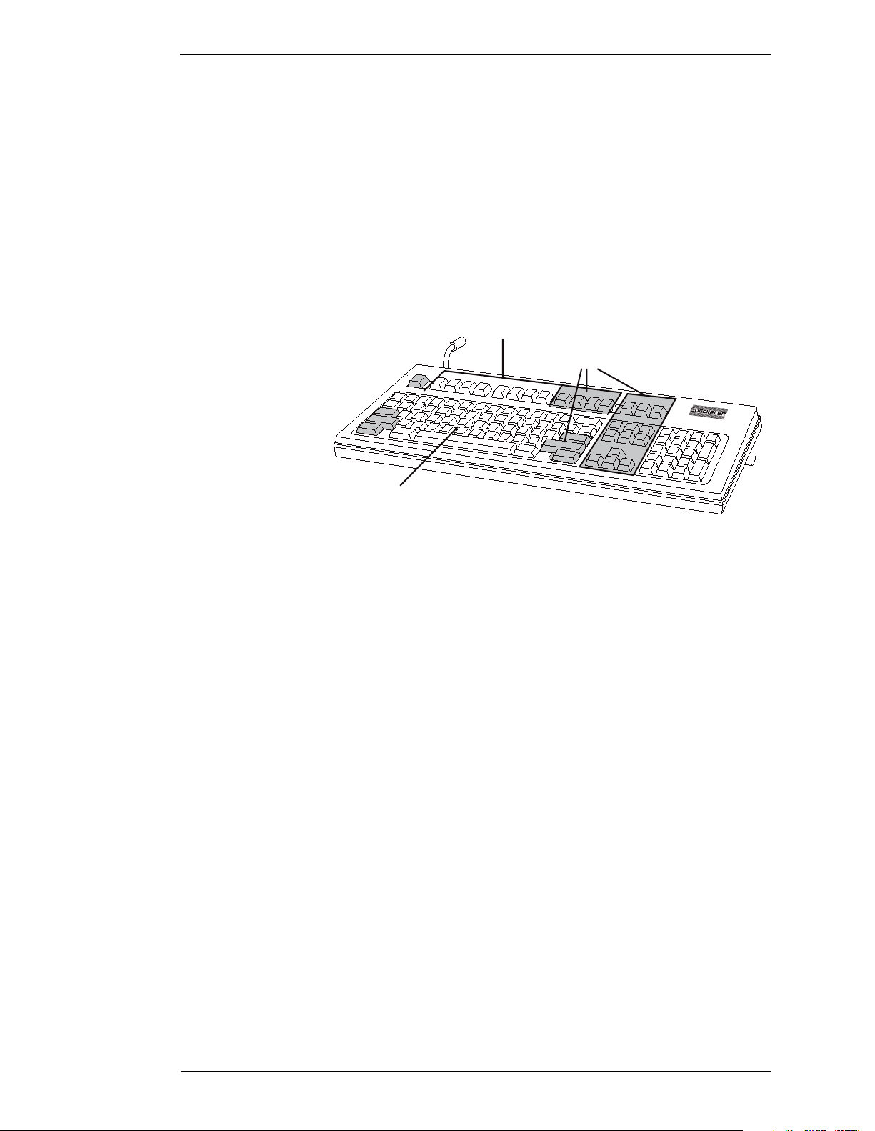
Keyboard Controller
The Pointmaker KB-30 Keyboard, diagrammed below, comes standard with
all PVI-65 models. It can be used to select, type, position, save and erase
Pointmaker markers, along with changing their appearance. When the keyboard is attached, it becomes the only way to access the menu system.
Refer back to this section, if needed, for general instructions concerning its
use.
MARKER K EYS
(Graphics)
ACTION KEYS
MARKER KEYS
(Text/Numbers)
MARKER KEYS
Figure 1-6: Pointmaker Keyboard Controller
These keys allow op erators to s elect mark er s and the appearance
of those markers. Marker keys include
•POINTERS [F1]
•LINE STYLE [F2]
• FRAMES [F3]
• SIZE FRAMES [F4]
• STRAIGHT DRAW [F5]
•FONTS [F6]
• TEXT BKGRND ON/OFF [F7]
• SHOW DATE/TIME [F8]
Auxiliary functions associated with several of these keys are
activated by pressing CTRL + the marker key. Auxiliary func-
tions are:
• POINTER ON/OFF [CTRL + F1]
• FONT SIZE [CTRL + F6]
• SET DATE/TIME [CTRL + F8]
Boeckeler Instruments, Inc. Pointmaker PVI-65 HD/SD-SDI Broadcast Video Marker - Page 13
Page 24

Peripheral Devices Section One: Getting Started
TEXT KEYS
Text and number keys on the Pointmaker keyboard controller are
used to create labels or markers. Upper and lower case characters
are available. Each line of type may be freely positioned until it
is anchored (See “Active & Anchored Markers“ in “Section
Five: Using Markers” on page 61).
A
CTION KEYS
Action keys perform an action other than marking, such as positioning and anchoring a marker, changing the color of a marker,
entering the menu system or Help, moving to another marker
overlay, or erasing a marker. These keys include
•HELP [ESC]
• CHANGE COLOR [F9]
• CHANGE BRIGHTNESS [F10]
•OVERLAY ON/OFF [F12]
• MENU SYSTEM [PRINT SCREEN]
• GO TO OVERLAY # [SCROLL LOCK]
•ENTER KEY
•DROP [INSERT]
• ACTIVE MARKER OFF [HOME]
• PREVIOUS OVERLAY [PAGE UP]
• UNDO [DELETE]
• CLEAR ALL [END]
• NEXT OVERLAY [PAGE DOWN]
•CTRL
•SHIFT
• POSITIONING KEYS (LEFT, RIGHT, UP, AND
Marker and Cursor Movement
The POSITIONING (arrow) keys are the heart of movement when using the
keyboard as a controller. The “active” markers it creates “float” above the
overlay and may be pos itioned v erti cally by press ing the up and do wn k eys , or
horizontally using the right and left keys. Once the marker is where you want
it, it is anchored on the overlay by pressing the DROP [Insert] or ENTER key.
DOWN).
POSITIONING keys are also used for si zing frames b efore they are anchored.
You can also use them to navigate menus.
Page 14 - Pointmaker PVI-65 HD/SD-SDI Broadcast Video Marker Boeckeler Instruments, Inc.
Page 25

Section One: Getting Started Peripheral Devices
A complete list of commands for this controller is found in “Quick Reference
for Devices“ i n the “Appendix” on page A-5. Markin g is des cribe d in “Secti on
Five: Using Markers” starting on page 59.
Boeckeler Instruments, Inc. Pointmaker PVI-65 HD/SD-SDI Broadcast Video Marker - Page 15
Page 26
Peripheral Devices Section One: Getting Started
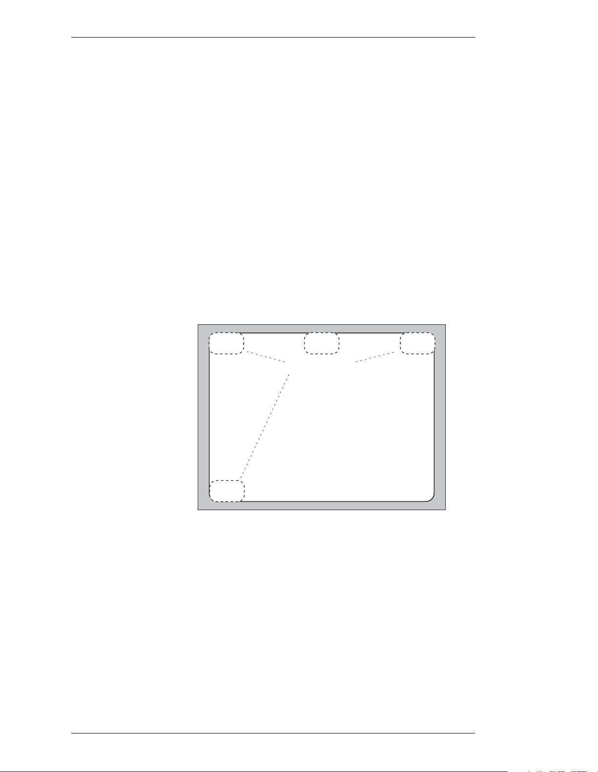
Touch Screen
The touch screen, diagrammed below, is not supplied or sold by Boeckeler
Instruments. Most touch screens on the market are compatible with the Pointmaker PVI-65. It is a very popular and intuitive control device.
Some display devices have integrated touch screens. It’s also likely that you
can attach a touch screen to a d isplay device you currently own. If you wish to
use one with your Pointmaker, check with your dealer or contact Boeckeler
Instruments directly for information regarding compatibility.
In general , the touch screen can be used to draw, position pointers or make
menu selections by touching or dragging your finger on the screen. There are
also four command areas which will activate Pointmaker functions when
touched.
Refer back to this section, if needed, for general instructions concerning its
use.
Color
Change
Clear
Markers
TRACKING AREA
The area on the touch screen where you draw and point using
your finger or other pointer.
UNCTION AREAS
F
The regions on the touch screen that, when tapped, activate a
function. Tapping the upper-left corner changes the color of the
next marker. Tapping the top center of the screen activates the
menu system (disabled if the k eyb oard is attached) . Tapping the
upper-right corner will undo/erase the most recent marker. Tapping the lower-left corner clears the screen of all markers.
Menu
Function Areas
Tracking
Area
Figure 1-7: Touch Screen Controller
Undo /
Erase
Page 16 - Pointmaker PVI-65 HD/SD-SDI Broadcast Video Marker Boeckeler Instruments, Inc.
Page 27

Section One: Getting Started Peripheral Devices
Marker and Cursor Movement
When operating the Pointmaker with a touch screen, the pointer will be displayed and anchored any time you tap the screen (unless the pointer is disabled). A pointer can’t be repositioned using the touch screen; however, it can
be cleared or erased from the screen. Drawing takes place when you press a
finger on the Tracking Area of the screen and drag across it. Menu selections
are made by tapping the menu selection you desire.
Calibrating the touch screen enhances the intuitive feel of drawing on the display and should be done upon the first installation and whenever a new touch
screen or monitor is used. (See “Controllers Requiring Calibration“ in “Sec-
tion Four: Comm Port Devices Menu” on page 49)
A complete list of commands for this controller is found in “Quick Reference
for Devices“ i n the “Appendix” on page A-5. Markin g is des cribe d in “Secti on
Five: Using Markers” starting on page 59.
Boeckeler Instruments, Inc. Pointmaker PVI-65 HD/SD-SDI Broadcast Video Marker - Page 17
Page 28
Peripheral Devices Section One: Getting Started
Mouse-type Devices
Numerous other drawing devices are compatible with the Pointmaker PVI-65
HD/SD-SDI Broadcast Video Marker. They fall into the general categories of
mouse controllers, trackballs, and wireless remote control devices. Boeckeler
Instruments does not supply or sell any of these products. These devices may
be used like a writing utensil to draw, position pointers, or move a cursor by
“dragging” the device across a mous e pad or (in the case of remote co ntrols) in
midair when aimed at the display.
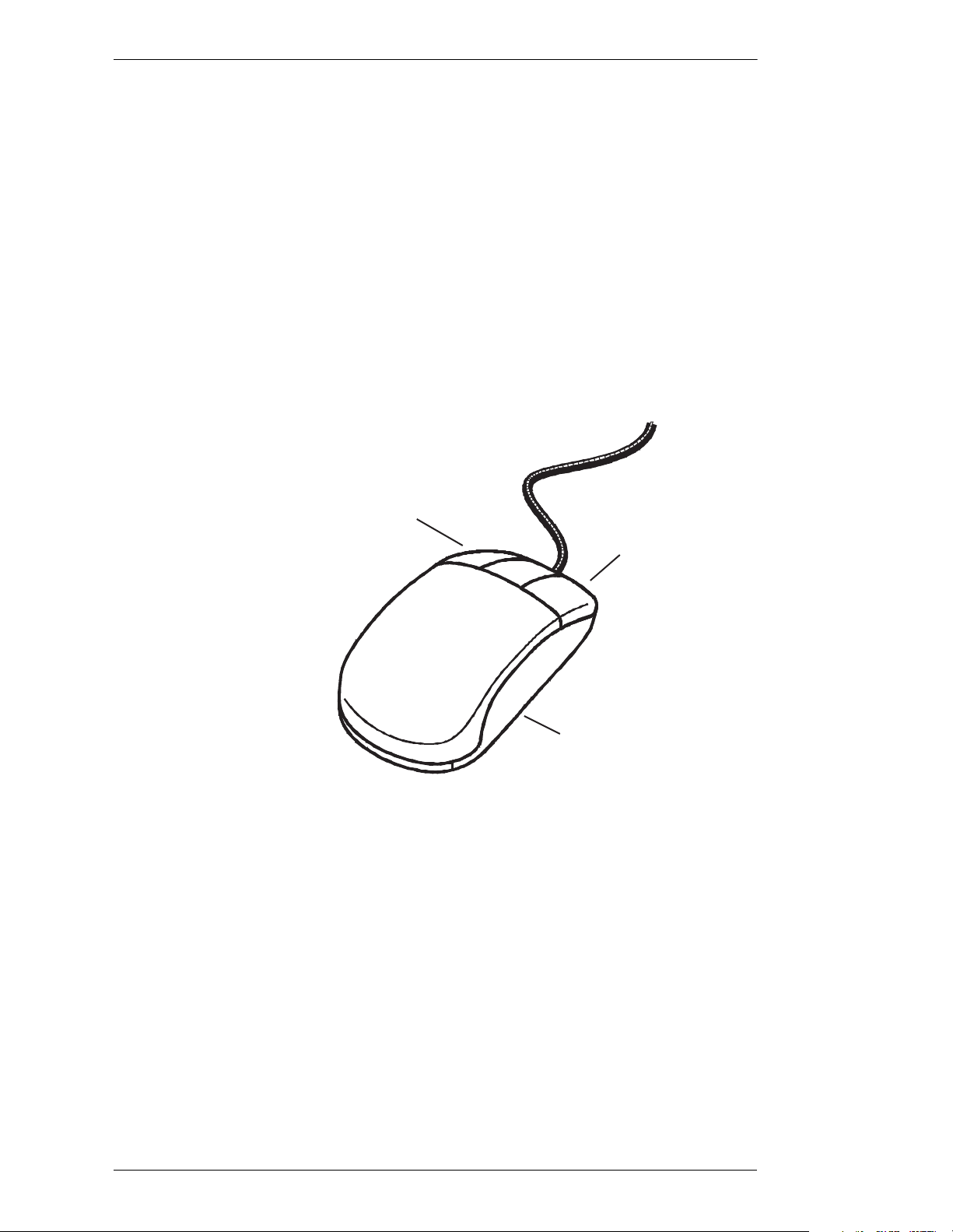
The diagram and definitions listed below are generalizations for how the
device might function connected to the Pointmaker . R efer back to this section,
if needed, for general instructions concerning their use.
Left Button
Right Button
Trackball
(underneath)
Figure 1-8: Mouse Device
There are so many of these types of de vices that comp atibility is probably best
determined by simply trying the device. If it can be used as a mouse-type
device on a personal computer, it is likely to work with the Pointmaker.
EFT OR FIRST BUTTON
L
When clicked, the Left or First Button anchors pointers on the
screen at the point they were positioned. Freehand drawing is
accomplished when this button is pressed do wn while co ntinuing
to write or draw with the device across a smooth surface or in
midair (in the case of a remote control).
Page 18 - Pointmaker PVI-65 HD/SD-SDI Broadcast Video Marker Boeckeler Instruments, Inc.
Page 29

Section One: Getting Started Peripheral Devices
RIGHT OR SECOND BUTTON
When clicked, this button erases the most recently anchored
marker. When pressed, this button clears the screen entirely of
markers.
B
OTH BUTTONS
The two buttons can be used in combination to either change the
color of a marker or access the menu system. Menu access from
the mouse device is disabled if the keyboard is connected.
Marker and Cursor Movement
When operating the Pointmaker with the mouse device, the cursor or active
pointer may be moved anywhere on the screen by moving the device's track
ball or by moving the remote control in midair. The active pointer or cursor
will move respectively. For example, "dragging" the mouse to the left on the
mouse pad, rotating a track ball to the left or aiming the remote control to the
left of the remote receiver will correspo ndin gly move the pointer to the left on
the screen. Directing the device to the right while drawing will draw a line to
the right.
A complete list of commands for this controller is found in “Quick Reference
for Devices“ i n the “Appendix” on page A-5. Markin g is des cribe d in “Secti on
Five: Using Markers” starting on page 59.
Boeckeler Instruments, Inc. Pointmaker PVI-65 HD/SD-SDI Broadcast Video Marker - Page 19
Page 30

Peripheral Devices Section One: Getting Started
Page 20 - Pointmaker PVI-65 HD/SD-SDI Broadcast Video Marker Boeckeler Instruments, Inc.
Page 31

Section One: Getting Started Installation
INSTALLATION
Installation of the Pointmaker PVI-65 can be divided into the following three
areas:
• Connect Video Source and Output(s)
• Connect Control Device(s)
• Power Up (leaving PVI-65 to last)
Connecting Video Source and Output(s)
The PVI-65 supports video input/output only from SD-SDI or HD-SDI compatible devices. For these connections, (See “Cutaway of back panel showing
video input/output connectors.” below.).
1. Use a BNC cable to connect your HD/SD-SDI source to the port
labeled HD/SD-SDI IN.
HD/SD-SDI OUT
2
KEY
Figure 1-9: Cutaway of back panel showing video input/output connectors.
1
HD/SD-SDI IN
2. Use a BNC cable to connect either or both video output(s) to the
port(s) labeled HD/SD-SDI OUT.
Port #1 is a Pre vie w out, combining your vide o input wit h annotation .
Port #2 can be programmed to function as Program, Key or Preview
out. (See “ Programming Video Mode“ in “Section Three: Display
Menu” on page 43)
Connecting Control Devices
The PVI-65 allows up to 10 different control devices to be attached, including
a keyboard. The following steps describe how to set up some of the most popular devices. For help in locating connectors on the Pointmaker, refer to “Cut-
away of back pa nel, showing power and controller connectors.” on page 22.
Boeckeler Instruments, Inc. Pointmaker PVI-65 HD/SD-SDI Broadcast Video Marker - Page 21
Page 32

Installation Section One: Getting Started
NOTE: Be sure the Pointmaker is powered down before connecting or disconnecting any controllers. It will automatically detect
the controllers inst alled up on power up. If users ch ange controll ers or
add a new controller, they will need to power down, install the new
controller(s), then power up.
POWER COMM. 2COMM. 1 KEYBDUSB
1
2
Figure 1-10: Cutaway of back panel, showing power and controller connectors.
Connecting the KB-30 Keyboard:
NOTE: Make all connections before applying power.
NOTE: If you are connecting both the keyboard and the digitizing
tablet, skip these instructions and proceed to the next section for connecting a digitizing tablet.
1. Connect the Pointmaker keyboard cable to the KEYBD port on the
back of the Pointmaker.
This is a female PS/2 port.
Connecting a DT-30 Digitizing Tablet:
1. Connect the stylus to the digitizing tablet.
2. Usi n g the RS-232 cable provided with the digitizing tablet, connect
the female 9-pin connector to a COMM port on the back of the Pointmaker.
3. Connect the power cable (which runs off the tablet cable) to the keyboard adapter cable provided with the digitizing tablet.
There is only one way to plug in these connectors.
4. Connect one end of the keyboard adapter cable to the female KEYBD
connector on the back of the Pointmaker (for power).
NOTE: If the keyboard is also being attached, connect the other end
of the keyboard adapter cable to the Pointmaker keyboard. The extra
cable that runs off the keyboard adapter cable is extraneous for applications where the Pointmaker keyboard is not connected.
Page 22 - Pointmaker PVI-65 HD/SD-SDI Broadcast Video Marker Boeckeler Instruments, Inc.
Page 33

Section One: Getting Started Installation
Tablet Mini-DIN
Adapter
Power Cable
Tablet Cable
To Pointmaker
COMM Port
Figure 1-11: Connections for the Pointmaker DT- 30 Digitizing Tablet
To Pointmaker
Keyboard Port
Keyboard
Adapter Cable
Stylus or Pen
Connecting a Touch Screen
To Pointmaker
Keyboard
(or not used)
NOTE: Make all connections before applying power.
Upon first power up, or whenever a new monitor is connected, the
touch screen should be calibrated.
NOTE: If the touch screen is to be your only or first control device,
it’s important to calibrate it at start up. Be sure to review “Controllers
Requiring Calibration“ in “Section Four: Comm Port Devices
Menu” on page 49 before you do the initial power up.
1. Connect the RS-232 interface to a COMM port on the back of the
Pointmaker .
As indicated in the diagram below, there will also be a video connection for the monitor.
Boeckeler Instruments, Inc. Pointmaker PVI-65 HD/SD-SDI Broadcast Video Marker - Page 23
Page 34

Installation Section One: Getting Started
Video IN
Video OUT
Pointmaker
COMM PORT
Figure 1-12: Typical Touch Screen Connections
Change
Color
*Menu System is disabled if keyboard is attached.
Menu
System
Figure 1-13: Touch Screen Labels
Undo /
Erase
Touch Screen
and Monitor
Clear
Markers
RS-232
IN
If desired, copy the touch screen labels above, cut them out and affix
them to the corresponding corn ers o f the touch s creen . This may help
presenters unfamiliar with touch screen functions. Each label identifies the function of its assigned corner (the filled block in the corner
of each square identifies the corner of the monitor where it should be
placed).
NOTE: Stickers of touch screen labels are available from Boeckeler
Instruments at (800) 552-2262 or (520) 745-0001.
Connecting a Mouse Device:
1. Using the 9-pin adapter provided, connect the mouse pen/device cable
to a COMM port or USB port on the back of the Pointmaker.
Page 24 - Pointmaker PVI-65 HD/SD-SDI Broadcast Video Marker Boeckeler Instruments, Inc.
Page 35

Section One: Getting Started Activation
ACTIVATION
Power Up
1. Plug the power cord of the inline power supply into the back of the
Pointmaker and then into any grounded outlet.
2. Power up your video source and controller(s), if needed.
3. Press the power button on the Pointmaker.
NOTE: In order f or the Pointmaker to properly sync with the video
signals, the source should be turned on first.
After a moment, the display will show a video image. A copyright
message will briefly appear. This is followed by port initialization.
After initialization, users will be presented with a marker overlay displaying any previously anchored markers. If this overlay is not properly displayed, recheck installation or call Boeckeler Instruments for
service at (800) 552-2262 or (520) 745-0001.
Menu Basics
Activating the Menu
NOTE: To bypass port initialization, press ESC.
If the keyboard is installed, it is the only way you can enter the menu system.
If the keyboard is not installed, you can access the menu system from one of
the other control devices.
Keyboard: Press Menu System[Print Screen] key.
Boeckeler Instruments, Inc. Pointmaker PVI-65 HD/SD-SDI Broadcast Video Marker - Page 25
Page 36

Activation Section One: Getting Started
MAIN MENU
ANNOTATION
DISPLAY
COMM PORT
DEVICES
HELP
EXIT
Figure 1-14: PVI-65 Main Menu
Digitizing Tablet: Press and hold the Barrel Button, then the Tip Button
on the drawing area. Keep both pressed for about 5 seconds.
NOTE: Press the tip button soon after the barrel button, or the PVI-65
may interpret the barrel button press as a “clear” command.
Touch Screen (or White Board): Tap upper center zone.
Mouse Device: Press Right (Second) Button, then Left (First) Button,
pressing both together for about 5 seconds.
Making Menu Selections
Once the menu system is displayed, you can make selections from it to navigate to the option(s) you wish to change. A selection from the Main Menu
causes a submenu to appear ne xt to it. A selection from the submenu displays a
second submenu of choices based on the selection you make. The menu structure is an outline format that allows you to “drill down” to the specific option
you wish to change. Whenever the Main Menu is visible, you can select
directly from it to activate a different branch of submenus.
Digitizing Tablet: Move pen tip lightly across the active area of the tablet
until your selection is highlighted. Push the tip to select.
Keyboard: Use arrow keys to highlight sel ection and pr ess the Enter key.
Touch Screen (or White Board): Tap the screen over the option you want
to select.
Mouse Devices: Click Left Button on your selection.
Page 26 - Pointmaker PVI-65 HD/SD-SDI Broadcast Video Marker Boeckeler Instruments, Inc.
Page 37

Section One: Getting Started Activation
ANNOTATION MENU
POINTERS
ERASE METHOD
LINE STYLE
COLOR PALETTE
BRIGHTNESS
PEN PROXIMITY
Figure 1-15: Sample Submenu (Annotation)
Exiting Menus
Exit a submenu by selecting any option in the Main Menu.
Exit the Main Menu by selecting EXIT.
Built-in Help Messages
The Pointmaker Help Menu that is accessed in the menu system offers operational help for auxiliary controllers such as the digitizing tablet, mouse device,
and touch screen plus so me more general ized help inf ormation. Keyboard help
is accessed directly from the ke yboard by pressing the HEL P [Esc] key. If presenters elect to use a hard copy version of help instead, a master for index
card-sized “Quick Notes” is provided at the conclusion of this section.
Accessing Help Messages
1. Activat e the Main Menu.
2. Select the HELP option.
Boeckeler Instruments, Inc. Pointmaker PVI-65 HD/SD-SDI Broadcast Video Marker - Page 27
Page 38

Activation Section One: Getting Started
HELP MENU
MOUSE DEVICE
DIGITIZING TABLET
TOUCH SCREEN
GENERAL INFORMATION
Figure 1-16: Help Menu
The Help Menu appears.
3. In the Help Menu, select the desired option.
Choosing the DIGITIZING TABLET option, for example, will display help messages that specifically pertain to tablet operating pr ocedures.
4. In the Help Submenu, select the desired help topic.
The Main Menu and Help Submenu will disappear, and the selected
Help Message will appear on-screen.
5. To ex it a help message, f ollow the simple exit instructions displayed in
each help message.
You will be returned to the Help Submenu.
6. To back up one menu from the Help Submenu, select the PREVIOUS
MENU option.
7. To exit all help menus, select any option in the Main Menu.
Accessing Keyboard Help Messages
The keyboard must be attached for this help function to operate.
1. Press HELP [Esc], followed by the function key for which you desire
help.
The Help Menu corresponding to the function key pressed will
appear on-screen.
2. To exit the help press ENTER.
Page 28 - Pointmaker PVI-65 HD/SD-SDI Broadcast Video Marker Boeckeler Instruments, Inc.
Page 39

SECTION TWO: ANNOTATION MENU
Page 40

Page 41

Section Two: Annotation Menu Annotation Settings
ANNOTATION SETTINGS
This section describes all of the options available in the Annotation Menu.
Also included, when applicable, are instructions for making the same selections usin g other controllers.
NOTE: Keep in mind that when the keyboard is attached, it becomes
the only way to access the menu system. However, once the menu is
activated, other controllers can make selections from it.
Instructions for operating the menu system are covered earlier in this manual.
(See “Menu Basics“ in “Section One: Getting Started” on page 25)
Pointers
There are several ways to s elect a po inters: fro m the tablet template, k e yboard ,
or menu system. Instructions for using the pointers are covered in detail in
“Section Five: Using Markers” starting on page 59.
1. Activate the menu system.
(See “Activating the Menu“ in “Section One: Getting Started” on
page 25)
The Main Menu appears. (See F igu re 1- 14:, “PVI-65 Main Menu” on
page 26)
2. Select Annotation.
ANNOTATION MENU
ERASE METHOD
COLOR PALETTE
PEN PROXIMITY
POINTERS
LINE STYLE
BRIGHTNESS
Figure 2-1: Annotation Menu
The Annotation menu appears.
Boeckeler Instruments, Inc. Pointmaker PVI-65 HD/SD-SDI Broadcast Video Marker - Page 31
Page 42

Annotation Settings Section Two: Annotation Menu
3. Select the POINTERS option.
POINTERS
NO POINTER
Figure 2-2: The Pointers dialog.
The Pointers dialog appears.
4. Select the pointer desired.
The selected pointer will highlight.
NOTE: Select “No Pointer” if you want the pointer hidden from view.
5. Exit the menu system.
Selecting an Erase Method
This option allows you to select the method you prefer for erasing markers:
using a “block” eraser to remove any parts you choose, or using the “Undo”
command to remove the most recently anchored marker. The block eraser has
three sizes: small, medium, and large.
1. Activate the menu system.
(See “Activating the Menu“ in “Section One: Getting Started” on
page 25)
The Main Menu appears. (See F i gur e 1-14:, “PV I-65 Main Menu” on
page 26)
2. Select Annotation.
Page 32 - Pointmaker PVI-65 HD/SD-SDI Broadcast Video Marker Boeckeler Instruments, Inc.
Page 43

Section Two: Annotation Menu Annotation Settings
The Annotation menu appears. (See Figure 2-1:, “Annotation Menu”
on page 31)
3. Select Erase Method.
ERASE METHOD
SMALL ERASER
MEDIUM ERASER
LARGE ERASER
UNDO
Figure 2-3: Erase Method dialog
The Erase Method dialog appears.
4. Select either an eraser size or Undo.
5. Exit the menu system.
Selecting a Line Style
This selection gives you a choice of three line thicknesses, with or without line
shadows.
1. Activate the menu system.
Both methods cannot be used at the same time.
Caution: When changing from undo to eraser mode, all current
annotations are deleted.
(See “Activating the Menu“ in “Section One: Getting Started” on
page 25)
The Main Menu appears. (See F igu re 1- 14:, “PVI-65 Main Menu” on
page 26)
2. Select Annotation.
The Annotation menu appears. (See Figure 2-1:, “Annotation Menu”
on page 31)
3. Select the Line Style option.
Boeckeler Instruments, Inc. Pointmaker PVI-65 HD/SD-SDI Broadcast Video Marker - Page 33
Page 44

Annotation Settings Section Two: Annotation Menu
LINE STYLE
Lines
with
shadows
Figure 2-4: Line Style dialog
The Line Style dialog appears.
4. Select the line style you desire.
5. Exit the menu system.
Customizing the Color Palette
With this menu, you can select which colors (out of a pool of 7) are available
during a presentation. It also lets you set an option for displaying the currently
selected color on-screen.
During a presentation, control devices (other than the tablet) select colors by
cycling through whatever colors are enabled in this menu. Each time a button
on the controller is pressed, the next co lor in the c y cle is activated. If you only
like to use two or three colors out of the seven, it’s more efficient to turn the
others off. The Color Palette menu gives you that ability.
1. Activate the menu system.
(See “Activating the Menu“ in “Section One: Getting Started” on
page 25)
The Main Menu appears. (See F i gur e 1-14:, “PV I-65 Main Menu” on
page 26)
2. Select Annotation.
The Annotation menu appears. (See Figure 2-1:, “Annotation M enu”
on page 31)
3. Select the COLOR PALETTE option.
Page 34 - Pointmaker PVI-65 HD/SD-SDI Broadcast Video Marker Boeckeler Instruments, Inc.
Page 45

Section Two: Annotation Menu Annotation Settings
COLOR PALETTE
WHITE
BLACK
PINK
RED
Figure 2-5: Color Palette Menu
BLUE
YELLOW
GREEN
DISPLAY
COLOR
CHANGE
The Color Palette Menu appears.
4. Select the colors you wish to use during the presentation.
A minimum of one color must be selected. If only one color is
selected, users will be able to deselect this color only after a second
color is chosen.
Only the colors surrounded by a solid fill will be available to the user
during the presentation.
5. Enable or disable the DISPLAY COLOR CHANGE option.
When this option is enabled, a small block of color will briefly appear
in the lower-right of the screen each time you change colors during a
presentation, making it easy for touch screen users to tell which color
is currently selected.
For broadcasters and certain other presenters, the color block appearing on-screen may not be desirable. In these cases it is advised that
the DISPLAY COLOR CHANGE opt ion be disabled .
NOTE: Because there is no need for a color block display with the
Pointmaker digitizing tablet, the DISPLAY COLOR CHANGE
option has no affect when using that controller.
6. Exit the menu system.
Boeckeler Instruments, Inc. Pointmaker PVI-65 HD/SD-SDI Broadcast Video Marker - Page 35
Page 46

Annotation Settings Section Two: Annotation Menu
Changing Colors Using the Digitizing Tablet:
Digitizing Tablet users do not need to access the menu system to
select a marker color. They may simply press the tablet icon depicting
the color desired. Choices made on the tablet override any selections
made in the Color Palette Menu.
Setting an Overlay Brightness Level
This option lets you select a brightness level for all displayed markers on any
particular overlay, helping you create optimum contrast between Pointmaker
graphics and the video image. This makes it possible to assign a different
brightness level for each of the 25 overlays. For more on overlays, see
“Manipulating Overlays“ in “Section Five: Using Markers” on page 79.
Brightness is most easily controlled from the keyboard or the Presenter template. Controllers other than the keyboard must use the menu system to change
the brightness level.
NOTE: Adjust the brightness after placing at least one marker on the
current overlay.
1. Activate the menu system.
(See “Activating the Menu“ in “Section One: Getting Started” on
page 25)
The Main Menu appears. (See F i gur e 1-14:, “PV I-65 Main Menu” on
page 26)
2. Select Annotation.
The Annotation menu appears. (See Figure 2-1:, “Annotation M enu”
on page 31)
3. Select the BRIGHTNESS option.
Page 36 - Pointmaker PVI-65 HD/SD-SDI Broadcast Video Marker Boeckeler Instruments, Inc.
Page 47

Section Two: Annotation Menu Annotation Settings
SET BRIGHTNESS
OK
Figure 2-6: Set Brightness dialog
The Brightness Menu appears.
4. Adjust the sliding scale using any of the following methods:
• Move the colored slider by drag ging it lef t or right.
• Click on the plus or minus at each side of the scale to move the
slider in small increments.
• Click on the scale itself to move the slider to the desired location.
Adjust the brightness controls until the marker displays the desired
brightnes s level.
NOTE: Moving the cursor to the left will decrease brightness. Moving the cursor to the right will increase brightness. If the brightness is
set too high for the monitor, the markers will smear across the image.
5. Exit the menu system.
Setting a Brightness Level Using the Keyboard
1. Repeatedly press the CHANGE BRIGHTNESS [F10] key until the
marker displays the desired brightness level.
To scroll backwards through the brightness options, press SHIFT +
CHANGE BRIGHTNESS [F10].
NOTE: Brightness selections on the keyboard override any setti ngs
made in the menu system.
Boeckeler Instruments, Inc. Pointmaker PVI-65 HD/SD-SDI Broadcast Video Marker - Page 37
Page 48

Annotation Settings Section Two: Annotation Menu
Changing Pen Proximity
When Pen Proximity is activated, the active pointer will disappear as the pen
tip is moved away from the digitizing tablet. When Pen Proximity is deactivated, the active pointer will remain on-screen even when the pen is pulled
away from the tablet.
NOTE: This assumes the active pointer has not been turned off (See
“Turning the Active Pointer On/Off“ in “Section Five: Using Markers” on page 65).
Changing Pen Proximity
1. Activate the menu system.
(See “Activating the Menu“ in “Section One: Getting Started” on
page 25)
Pointer Toggle
The Main Menu appears. (See F i gur e 1-14:, “PV I-65 Main Menu” on
page 26)
2. Select Annotation.
The Annotation menu appears. (See Figure 2-1:, “Annotation M enu”
on page 31)
Notice that the Pen Proximity selection is displayed near the bottom.
NOTE: If the Pen Proximity option box displays a solid fill, it is
active. If it is not filled, Pen Proximity is inactive.
3. Select the PEN PROXIMITY option to turn it on or off.
The fill in the Pen Proximity box will reflect the new status selected.
4. Exit the menu system.
The ENABLE POINTER TOGGLE option gives you the ability to hide the
pointer during a presentation. You might want to engage this option if you
expect to be drawing most of the time, rather than pointing, or if you need a
pointer only occasionally. If it is activated, you can turn the pointer on or off
during a presentation. When deactivated, the pointer remains visible at all
times.
Page 38 - Pointmaker PVI-65 HD/SD-SDI Broadcast Video Marker Boeckeler Instruments, Inc.
Page 49

Section Two: Annotation Menu Annotation Settings
1. Activate the menu system.
(See “Activating the Menu“ in “Section One: Getting Started” on
page 25)
The Main Menu appears. (See F igu re 1- 14:, “PVI-65 Main Menu” on
page 26)
2. Select Annotation.
The Annotation menu appears. (See Figure 2-1:, “Annotation Menu”
on page 31)
3. Select the Enable Pointer Toggle option to turn it on or off.
NOTE: If the Enable Pointer T o ggle button has a solid fill, it is active.
If it is not filled, it is inactive.
4. Exit the menu system.
To toggle the pointer off or on during a presentation:
Mouse:
1. First press the second button, then press the first button so that both
buttons are pressed until the pointer disappears. Then release both
buttons. To make the pointer reappear, repeat the same procedure.
Digitizing Tablet:
1. Use the pen to click on the POINTER ON/OFF icon on the tablet
Menu.Strip. The pointer will disappear. To make the pointer reappear, repeat the same procedure.
Touch Screen
1. Because there is no active pointer on a touch screen, the ENABLE
POINTER TOGGLE is inactive.
If users wish to turn off the pointer , they can select NO POINTER in
the Pointer Selection Menu.
Boeckeler Instruments, Inc. Pointmaker PVI-65 HD/SD-SDI Broadcast Video Marker - Page 39
Page 50

Annotation Settings Section Two: Annotation Menu
Page 40 - Pointmaker PVI-65 HD/SD-SDI Broadcast Video Marker Boeckeler Instruments, Inc.
Page 51

SECTION THREE: DISPLAY MENU
Page 52

Page 53

Section Three: Display Menu The Dis p lay Menu
THE DISPLAY MENU
Programming Video Mode
The second video out port, labeled HD/SD-SDI OUT 2, can be programmed
for any of three different outputs:
1) Program - video with annotation, no menus.
2) Key - outputs a key signal of annotation, no menus.
3) Preview - video with annotation, menus.
4) Passthrough - passes video signal through unchanged.
1. Activate the menu system.
(See “Activating the Menu“ in “Section One: Getting Started” on
page 25)
The Main Menu appears. (See F igu re 1- 14:, “PVI-65 Main Menu” on
page 26)
2. Select the Display option.
DISPLAY MENU
PROGRAM VIDEO MODE
ZAP ON
TOUCH SCREEN CORNERS ON
Figure 3-1: The Display Menu.
The Display menu appears.
3. Select the PROGRAM VIDEO MODE option.
Boeckeler Instruments, Inc. Pointmaker PVI-65 HD/SD-SDI Broadcast Video Marker - Page 43
Page 54

The Display Menu Section Three: Display Men u
PROGRAM VIDEO MODE
PROGRAM
KEY
PREVIEW
PASSTHROUGH
Figure 3-2: Program Video Mode Menu
The Program Video Mode menu appears.
4. Select the mode desired.
Program is video without annotation.
Key is a key signal.
Preview is video with annotation.
5. Exit the menu system.
Port #2 now outputs the selected video mode.
Turning Zap Icon On/Off
This selection toggles the disp la y of the Zap ico n on an d off. When turned on,
it is displayed in the lower right hand corner of the screen. This is useful if you
are switching between other video sources that are not connected to the PVI-
65. With the Zap icon displayed, it will be clear when you are displaying video
from the PVI-65.
Figure 3-3: Zap Icon
1. Activate the menu system.
(See “Activating the Menu“ in “Section One: Getting Started” on
page 25)
Page 44 - Pointmaker PVI-65 HD/SD-SDI Broadcast Video Marker Boeckeler Instruments, Inc.
Page 55

Section Three: Display Menu The Display Menu
The Main Menu appears. (See F igu re 1- 14:, “PVI-65 Main Menu” on
page 26)
2. Select the DISPLAY option.
The Display menu appears. (See Figure 3-1:, “The Display Menu.”
on page 43).
3. Activate the ZAP ON button.
When active, the button contains a solid color fill. Each activation of
the button toggles it to the opposite state.
4. Exit the menu system
Turning Touch Screen Function Areas On/Off
This selection activates/deactivates the touch sensitive function areas used
with the touch screen controller. (See “Touch Screen“ in “Section One: Get-
ting Started” on page 16) When activated, the function areas are sensitive to
touch. When deactivated, they will not respond to touch.
Color
Change
Menu
Function Areas
Undo /
Erase
Tracking
Area
Clear
Markers
Figure 3-4: Touch Screen Controller
1. Activate the menu system.
(See “Activating the Menu“ in “Section One: Getting Started” on
page 25)
The Main Menu appears. (See F igu re 1- 14:, “PVI-65 Main Menu” on
page 26)
Boeckeler Instruments, Inc. Pointmaker PVI-65 HD/SD-SDI Broadcast Video Marker - Page 45
Page 56

The Display Menu Section Three: Display Men u
2. Selec t the DISPLAY option.
The Display menu appears. (See Figure 3-1:, “The Display Menu.”
on page 43).
3. Activate the TOUCH SCREEN CORNERS ON button.
When active, the button contains a solid color fill. Each activation of
the button toggles it to the opposite state.
4. Exit the menu system
Page 46 - Pointmaker PVI-65 HD/SD-SDI Broadcast Video Marker Boeckeler Instruments, Inc.
Page 57

SECTION FOUR: COMM PORT DEVICES MENU
Page 58

Page 59

Section Four: Comm Port Devices Menu Comm Port Operations
COMM PORT OPERATIONS
This section covers the various settings and options available through the use
of the COMM ports on the PVI-65.
Controllers Requiring Calibration
Controllers which require calibration are: remote control, touch screen and
white boar d.
If you are using any of these as your initial controller, Boeck e ler recommends
calibrating them upon first power up. They can also be calibrated at any time
using the selections in this part of the menu system if you are using the digitizing tablet or keyboard as your initial controller.
Calibrating the Remote Control, Touch Screen or White Board at Start
Up:
1. Power up the Pointmaker and wait for the copyright message to
appear.
2. During the 8-second copyright message, activate the controller:
A. by touching the left button on the remote control
- OR -
B. by tapping once on the touch screen
- OR -
C. by tappi ng once on the Wh i te Board.
3. Follow the calibration instructions displayed on the screen.
After the calibration is complete, the Pointmaker will complete its
startup and be ready for use.
Calibrating the Remote Control, Touch Screen or White Board Using
the Menu System:
1. Activate the menu system.
(See “Activating the Menu“ in “Section One: Getting Started” on
page 25)
Boeckeler Instruments, Inc. Pointmaker PVI-65 HD/SD-SDI Broadcast Video Marker - Page 49
Page 60

Comm Port Operations Section Four: Comm Port Devices Menu
The Main Menu appears. (See F i gur e 1-14:, “PV I-65 Main Menu” on
page 26)
2. Select the COMM PORT DEVICES option.
COMM PORT DEVICES
CALIBRATION
MULTIPLE
CONTROLLERS
SERIAL PORTS
Figure 4-1: Comm Port Devices Menu
The Comm Port Devices menu appears.
3. Select the CALIBRATION option.
CALIBRATION MENU
REMOTE CONTROL
CALIBRATION
TOUCH SCREEN
CALIBRATION
WHITE BOARD
CALIBRATION
Figure 4-2: Calibration Me nu
The Calibration Menu appears.
4. In the Calibration Menu, select the controller to be calibrated.
Page 50 - Pointmaker PVI-65 HD/SD-SDI Broadcast Video Marker Boeckeler Instruments, Inc.
Page 61

Section Four: Comm Port Devices Menu Comm Port Operations
CALIBRATE TOUCH SCREEN
TOUCH UPPER LEFT TARGET
Figure 4-3: Calibrate Touch Screen dialog
The appropriate calibration screen appears.
5. Follow the calibration instructions displayed.
After users perform final calibration procedures, the Calibration Procedure display will automatically disappear, and users will be
returned to the menu system.
6. Exit the menu system.
Prioritizing Controller/Marker Usage
If desired, you can prioritize who’s controller/marker has precedence when
more than one is installed.
Three different modes are available:
OPEN mode: Allows all installed controllers to draw and point at
any time. All users may change the appearance of markers, including
clearing markers. However, while one user is drawing, no other user
can mark or change the appearance of markers.
SELECTIVE mode : Adds slightly more organization, requiring a
user to first select CONTROL on the tablet or touch screen before
they begin marking. Again, while one user is drawing, no other user
can mark or change the appearance of markers. This option only
works with digitizing tablets and touch screens. Other controllers
continue to work in the OPEN mode.
PRIORITY USER mode: This mode allows one pre-assigned user
to take and re l ease control of marking fu nctions. On first use, the Priority User assigned in this menu is in control. While in control, a
small “zap” character icon will appear in the lower-right corner of the
Boeckeler Instruments, Inc. Pointmaker PVI-65 HD/SD-SDI Broadcast Video Marker - Page 51
Page 62

Comm Port Operations Section Four: Comm Port Devices Menu
screen. When the Priority User is in control, no other user can take
control of marking functions. The Priority User can release control to
other users by again selecting CONTROL on the tablet or touch
screen. Use is then similar to the SELECTIVE mode: users must
select CONTROL in order to m ark or change marker appearance. The
Priority User can take exclusive control at any time by selecting
CONTROL. Thi s op tio n o nly works with digitizing ta blet s and touch
screens. Other controllers work in the OPEN mode.
To Set a Priority Mode:
1. Activate the menu system.
(See “Activating the Menu“ in “Section One: Getting Started” on
page 25)
The Main Menu appears. (See F i gur e 1-14:, “PV I-65 Main Menu” on
page 26)
2. Select COMM PORT DEVICES.
The Comm Port Devices Menu appears (See Figure 4-1:, “Comm
Port Devices Menu” on page 50).
3. Select MULTIPLE CONTROLLERS.
MULTIPLE-USER OPTIONS
MODE
OPEN
SELECTIVE
PRIORITY USER
Selecting PRIORITY
USER option requires
designating a priority
COMM # (below).
PRIORITY COMM # 00 of 10
PRIORITY TO CURRENT
DIGITIZING TABLET
OR TOUCH SCREEN
Figure 4-4: Multiple-User Options dialog
The Multiple-User Options dialog appears.
Page 52 - Pointmaker PVI-65 HD/SD-SDI Broadcast Video Marker Boeckeler Instruments, Inc.
Page 63

Section Four: Comm Port Devices Menu Comm Port Operations
4. Select a priority mode.
If you select PRIORITY USER, identify the user by selecting their
port numbe r. It will highlight in pi nk when selected.(COMM port
numbers are printed on the back of the PVI-65 unit.)
5. Exit the menu system.
Serial Port Settings
Serial ports are used for two main purposes: 1) connecting controller/marker
devices 2) connecting to other systems (remote control, a second Pointmaker,
a PC). This section explains the options available to you for each purpose.
The Serial Port dialog also allows you to assign a priority system to control
users if multiple controller/markers are connected.
Configuring Device Types
Initialization of Device Types
Serial ports are “initialized” when the PVI-65 is powered on. During this process, the PVI-65 attempts to determine what device type ( controller/mark er) is
connected to each port. This procedure can be lengthy since the PVI-65
accommodates a wide range of devices, and in its default detection mode
(autodetect), it will run through the entire list of possibilities for each port.
Using the settings available in the Serial Ports menu, it is possible for you to
limit the initialization process for a designated port so that the PVI-65 looks
for only the device type you specify. This speeds up the initialization process
considerably.
Integrating the PVI-65 with Other Systems
Since only controller/marker de vice typ es are able to be recognized during the
initialization process, all other devices must be set up manually. The PVI-65
allows you to manually adjust communication settings for either of its COMM
ports(See “Se tting Comm Port Parameters” on page 56 ). This allows the PVI-
65 to be integrated with:
1) an A/V system as a remote control command station where it can
both control A/V devices and mark over any images presented;
2) a remote control system which can send commands to the PVI-65,
controlling its various functions (See “Section Six: Commands for
RS-232 Con trol” on page 81).
Boeckeler Instruments, Inc. Pointmaker PVI-65 HD/SD-SDI Broadcast Video Marker - Page 53
Page 64

Comm Port Operations Section Four: Comm Port Devices Menu
Designating a Device Type
1. Activate the menu system.
(See “Activating the Menu“ in “Section One: Getting Started” on
page 25)
The Main Menu appears. (See F i gur e 1-14:, “PV I-65 Main Menu” on
page 26)
2. Select COMM PORT DEVICES.
The Comm Port Devices Menu appears (See Figure 4-1:, “Comm
Port Devices Menu” on page 50).
3. Select SERIAL PORTS.
SERIAL PORTS
Control Port
1
unknown
2
Figure 4-1: Serial Ports Dial og
The Serial Ports dialog appears.
NOTE: All the serial ports installed on your PVI-65 are listed by port
number, with the de vice type displayed to the right of each number. If
the device type is in blue, it has been assigned through the autodetect
procedure at startup.
4. Select the device type you wish to have permanently assigned.
If the device type can be permanently assigned (some types cannot),
the color changes from blue to black. With the device permanently
assigned, the next time the PVI-65 is powered up, the autodetect procedure will skip this port. If the assigned device needs initialized at
startup, it will be initialized according to the device type listed.
Page 54 - Pointmaker PVI-65 HD/SD-SDI Broadcast Video Marker Boeckeler Instruments, Inc.
Page 65

Section Four: Comm Port Devices Menu Comm Port Operations
NOTE: If the device type listed for a port cannot be permanently
assigned (for example: device type “unknown” or if you try to assign
more than one port for use with other systems (See “Integrating the
PVI-65 with Other Systems” on page 53)), or you just wish to select a
different type, there are two ways to change it. The next two steps
describe how.
5. (optional) Select the arrow to the right of the device type you wish to
change.
DEVICE SELECT, PORT 2
Page Up
Calcomp TS
Computer
Control Port
Digitizer A
Do Not Use
Dynepro SC3
Dynepro SC4
Freedom Writer
Intellitouch
Page Down
Figure 4-2: Device Select Dialog
?
?
?
?
?
?
?
?
?
The Device Select dialog appears.
This dialog presents a s crolling list of all device types currently supported by the PVI-65 in alphabetical order. The Page Up and Page
Down buttons allow you to quickly scroll through the names until
you find the device type you desire. When you locate and select the
name you wish to assign, it will move to the center of the list, where it
will be highlighted. The new device type is now assigned.
Device types which cannot be selected are in white.
When a “?” button is selected, a screen with further information
about that device type will be displayed.
If a device type that is used for communicating with other systems is
selected, an arrow button will replace its “?” button. Selecting that
arrow button will activate the dialog for setting port parameters.
Boeckeler Instruments, Inc. Pointmaker PVI-65 HD/SD-SDI Broadcast Video Marker - Page 55
Page 66

Comm Port Operations Section Four: Comm Port Devices Menu
You can return to the Serial Ports dialog to make further changes by
selecting Comm Port Devices and then selecting Serial Ports.
NOTE: If you are designating a port for use with another system you
will need to set Comm Port parameters before exiting the menu system(See “Setting Comm Port Parameters” on page 56).
NOTE: The PVI-65 must be rebooted for the new device type assignments to be made permanent.
6. (optional) Select the device type name you wish to change.
When the device type name, instead of the arrow to its right, is activated, the device type will change without having to display the
Device Select submenu. This method is only recommended for those
with more extensive experience in assigning device types. Each time
the name is selected, it causes a different device type to appear. The
list of devices available using this method is an abbreviated version of
the list seen in the Device Select dialog.
A click on the right side of the name moves forward one device. A
click on the left side of the name mov es backwa rd on e de vi ce. (If yo u
are using the keyboard to select, it moves backward through the list
only.) Keep clicking until the device type you desire is displayed. It
will be assigned permanently when the PVI-65 is rebooted.
NOTE: If you are designating a port for use with another system you
will need to set Comm Port parameters before exiting the menu system(See “Setting Comm Port Parameters” on page 56).
NOTE: The PVI-65 must be rebooted for the new device type assignments to be made permanent.
7. Exit the menu system and recycle the power on the PVI-65.
The PVI-65 implements the new settings.
Setting Comm Port Parameters
If you are assigning a port for communicating with another system (See “Integrating the PVI-65 with Other Systems” on page 53), you must select either
Control Port or PVI to PVI as you r device type. The PVI-65 supports assigning only one port for each type.
Control Port: Choose this option if the PVI-65 is being used as an
A/V remote control command station or if it is being controlled
remotely using RS-232 commands.
Page 56 - Pointmaker PVI-65 HD/SD-SDI Broadcast Video Marker Boeckeler Instruments, Inc.
Page 67

Section Four: Comm Port Devices Menu Comm Port Operations
PVI-to-PVI: Use this selection if the PVI-65 is being us ed to connect
to another Pointmaker system.
1. Select the appropriate device type in the Device Select dialog for the
port where you are connecting the other system(See “Designating a
Device Type” on page 54).
Where a question mark is usually found, you will instead see an
arrow.
NOTE: If the device type you desire for connecting to other systems
is unavailable, check to see if it is assigned to another port. Remember, only one use of each is allowed.
2. Activate the arrow next to the device type to set its communication
parameters.
Control Port PORT #2
BAUD RATE PARITY STOP
9600
4800
2400
1200
600
300
110
Figure 4-3: Control Port Dialog
NONE
EVEN
ODD
SPACE
MARK
BITS
1
2
The corresponding dialog appears.
Select the desired baud rate, parity, and stop bits.
NOTE: F actory se ttings are 9600 ba ud, no par ity, 1 stop bit. Data bits,
which cannot be manually set, are 8 data bits.
3. Exit the menu system and recycle the power on the PVI-65.
The PVI-65 implements the new settings.
Boeckeler Instruments, Inc. Pointmaker PVI-65 HD/SD-SDI Broadcast Video Marker - Page 57
Page 68

Comm Port Operations Section Four: Comm Port Devices Menu
Page 58 - Pointmaker PVI-65 HD/SD-SDI Broadcast Video Marker Boeckeler Instruments, Inc.
Page 69

SECTION FIVE: USING MARKERS
Page 70

Page 71

Section Five: Using Markers Overview
OVERVIEW
This section covers marking procedures you might follow while making a presentation. It is assumed that you have basic familiarity with the operational
buttons of your control device, and how to use them to anchor a marker and
draw (See “Peripheral Devices“ in “Section One: Getting Sta rted” on page
9).
Basic Marking Concepts
Markers
Pointmaker Video Markers make it possible to create a variety of graphic
shapes (including text), called markers, which can be placed over a video
image. Available markers include: pointers, freehand drawing, typed text,
straight line drawing, sizeable frames, and a date/time label.
Control Devices
Markers are created or placed using one or more control or marking devices.
The most commonly used controllers are: digitizing tablets, keyboards, touch
screens and mouse devices. Each type of device has its own strengths and
weaknesses when used in a presentation.
Active & Anchored Markers
An active marker is a special kind of marker that “floats” over the image until
it is anchored or “fixed” into a location assigned by the user. While it is active,
its attributes can be altered. Depending on the type of marker being created,
some of those attributes are: position, color, size, line thickness, and shape.
Once a marker is anchored, its attributes cannot be changed. It can only be
removed and re-created or covered with another marker.
Any markers created with the keyboard are active markers. All other control
devices (except the touch screen) have only one type of active marker available: pointers.
Overlays
Markers never alter the displayed video images because they are actually
placed on a clear layer above th e imag e called an overlay. The Pointmaker can
store up to 25 differ ent o verlay s and each o v erlay can h old any combinatio n of
Boeckeler Instruments, Inc. Pointmaker PVI-65 HD/SD-SDI Broadcast Video Marker - Page 61
Page 72

Overview Section Five: Using Markers
markers. A user can prepare overlays in advance of a presentation and then
recall them at will when they are needed. Once an overlay is recalled, it can be
changed or erased. When the Pointmaker is powered down, it will automatically save the overlays in its memory.
Instructions for marking are divided into the following categories:
• Assigning Marker Appearance
• Marking
• Clearing Markers
• Displaying Different Overlays
Page 62 - Pointmaker PVI-65 HD/SD-SDI Broadcast Video Marker Boeckeler Instruments, Inc.
Page 73

Section Five: Using Markers Assigning Marker Appearance
ASSIGNING MARKER APPEARANCE
While the marker is still active, and before you begin to dra w or place markers,
you can change the appearance of your drawing or next marker in one of several ways.
• Assign Marker Color
• Assign Line Style
• Assign Pointer Type
• Turn Pointer On/Off
Assigning Marker Colors
The color that the active marker displays is the color that the marker will be
anchored in. You can anchor markers of different colors on a single overlay.
The colors available during a presentation are based on those activated in the
Color Palette menu (See “Customizing the C olor Palette“ in “Section Two:
Annotation Menu” on page 34).
If the color of the markers does not change from black, the brightness level is
too low and must be increased before selecting the color (See “Setting an
Overlay Brightness Level“ in “Section Two: Annotation Menu” on page 36).
From Any Controller
Activate the Change Color command from your control device.
(see “Quick Reference for Devices” in “Appendix” on page A-5)
All markers anchored from this point on will appear in the newly
selected color.
NOTE: If the pointer has been disengaged, and the Display Color
Change option in the Color Palette Menu has been activated, a small
block of color will briefly appear in the lower right of the screen to
help you identify the new marker color. The Display Color Change
block does not appear when using the digitizing tablet.
NOTE: In mouse devices, be careful to click the tip (or first) button
rather than press it. Pressing the tip (or first) button could inadvertently toggle the pointer on/off or cause the menu system to appear.
Boeckeler Instruments, Inc. Pointmaker PVI-65 HD/SD-SDI Broadcast Video Marker - Page 63
Page 74

Assigning Marker Appearance Section Five: Using Markers
Assigning Line Styles
You can have drawn lines of different styles on a single overlay. Once you
draw the line, or anchor a straight line, you cannot change that line style. However, you can erase or undo the drawing and begin again. (See “Clearing
Markers” on page 75)
You can change line style directly from the digitizing tablet or from the keyboard. You can also change the line style from other devices by accessing the
menu system. When the keyboard is installed, you can only access the menu
system from the keyboard.
From Digitizing Tablet
1. Click the pen tip on the desired line style icon on tablet.
All lines drawn from this point on will appear in the newly selected
line width a nd style.
From the Keyboard
1. Activate the Line Style command. (see “Quick Reference for K e yboar d”
in “Appendix” on page A-6)
A small sample of the active line style will appear briefly in the
lower-right hand corner of the screen.
2. Repeatedly activate the Line Style command until the desired line
style appears in the on screen sample.
You can scroll backwards through the line options, by activating the
Reverse Toggle command.
All lines drawn from this point on will appear in the newly selected
line width a nd style.
From the Menu System
(See “Selecting a Line St yle“ in “Section Two: Annotation Menu” on
page 33)
Page 64 - Pointmaker PVI-65 HD/SD-SDI Broadcast Video Marker Boeckeler Instruments, Inc.
Page 75

Section Five: Using Markers Assigning Marker Appearance
Selecting Pointers
Select a pointer type while the pointer is active, or positionable. After you
anchor the pointer, you cannot change that pointer’s type. However, you can
erase or undo the anchored pointer and begin again (See “Clearing Markers”
on page 75).
From the Digitizing Tablet
1. Click the pen tip on the desired pointer icon on tablet.
The corresponding active pointer appears on screen, ready for positioning or anchoring.
From the Keyboard
1. Repeatedly activate the POINTERS command until the desired
pointer type appears on screen. (see “Quick Refer en ce for K e yboar d” in
“Appendix” on page A-6)
You can scroll backwards through the pointer options, by activating
the Reverse Toggle command.
The pointer you selected appears on screen, ready for positioning.
From the Menu System
(See “Pointers“ in “Section Two: Annotation Menu” on page 31)
Turning the Active Pointer On/Off
Sometimes a presenter chooses not to have the pointer showing during a presentation. This command allows you to turn the visibility of the pointer off or
on. When the active pointer is turned off, you can still anchor pointers.
Since touch screens and whiteboard s do not displ ay acti ve poi nters, you do not
need to use the Pointer On/Off command with those devices.
NOTE: An alternative to the Pointer On/Off command, is using the
Pen Proximity feature available on the tablet template or through the
menu system. When active, this feature causes the active pointer to
disappear each time you remov e y our drawing device from p roximity
Boeckeler Instruments, Inc. Pointmaker PVI-65 HD/SD-SDI Broadcast Video Marker - Page 65
Page 76

Assigning Marker Appearance Section Five: Using Markers
of the tablet or screen drawing surface (See “Changing Pen Proximity“ in “Section Two: Annotation Menu” on page 38).
From the Digitizing Tablet
1. Press the Pointer On/Off icon on the tablet Menu Strip.
The pointer disappears.
2. To make the pointer reappear, repeat the procedure.
From the Keyboard
1. Activate the Pointer On/Off command. (see “Quick Reference for Key-
board” in “Appendix” on page A-6)
The pointer disappears.
2. To make the pointer reappear, repeat the procedure.
NOTE: To turn off all active marker s, including acti ve frames, use the
keyboard Active Marker On/Off command.
From the Menu System
Pointers are turned off in the same d ialog where th e y are selected. (See “P ointers“ in “Section Two: Annotation Menu” on page 31)
Page 66 - Pointmaker PVI-65 HD/SD-SDI Broadcast Video Marker Boeckeler Instruments, Inc.
Page 77

Section Five: Using Markers Marking
MARKING
This section covers pointing and drawing procedures. The following outline
lists the procedures in the general order that most presenters use them.
• Entering the Marking Mode
• Pointing (with positionable or anchored pointers)
•Drawing
• Typing Text (keyboard installed)
• Framing (keyboard installed)
• Stamping the Date/Time
Entering the Marking Mode
Pointing
From Any Controller
The Pointmaker is in the marking mode by default. The only time it is not in
marking mode is when a menu is displayed. In the Marking mode, the image
from the video source is displayed along with any stored markers. An active
pointer is also displayed, unless it was disabled during setup (See “Turnin g the
Active Pointer On/Off” on page 65).
You can move the pointer around the screen, using it to direct the viewer’s
attention without anchoring it. You can also p osition and anchor several pointers on the overlay, giving you the opportunity to point in a more lasting manner on several areas of the image.
Before using or anchoring a point er , you may w ant to select a new po inter type
(See “Selecting P o inter s” on pag e 65). Or you may change the pointer color
(See “Assigning Marker Colors ” on page 63).
1. Position the pointer anywhere on the video image to direct attention
to an image detail.
Refer to instructions for your particular control device (See “Peripheral Devices“ in “Section One: Getting Started” on page 9).
Boeckeler Instruments, Inc. Pointmaker PVI-65 HD/SD-SDI Broadcast Video Marker - Page 67
Page 78

Marking Section Five: Usin g M ar kers
2. If desired, reposition the same active pointer anywhere on the image
to make your second point, and continue as often as desired.
3. If desired, anchor the active po i n ter.
Refer to instructions for your particular control device (See “Peripheral Devices“ in “Section One: Getting Started” on page 9).
The pointer is anchored and a new active pointer appears on screen,
identical to the first.
NOTE: Active pointers are not displayed for touch screens, only
anchored markers.
4. Repeat any of these steps as often as desired.
Drawing
You can draw on the Pointmaker overlay simply by beginning to draw. The
drawing feature allows you to circle important parts of the image, write on the
image, or underscore particular parts of text. You can draw freehand curves or
straight lines.
To draw, you can use the digitizing tablet stylus on the tablet drawing area,
your finger on a touch screen, or a magic marker on the SMART Board. You
can also use other mouse devices to draw. You cannot freehand dra w u sing th e
keyboard, but you can use it for straight line drawing.
Before drawing, you may wish to change the drawing line color (See “Assign-
ing Marker Colors” on page 63). Or you may which to change the width and
style of the drawing line (See “Assigning Line Styles” on page 64).
Drawing Freehand
1. Position the active p oin ter ( if one i s di spl ay ed ) a ny where on the video
image where the drawing is to begin.
NOTE: If you are using a touch screen or white board, position a finger or marker pen.
2. Activate the Draw command from your particular drawing device.
(See “Peripheral Devices“ in “Section One: Getting Started” on
page 9)
3. Reposition the active marker (if one is displayed) and repeat the
above procedures for another drawn line.
Page 68 - Pointmaker PVI-65 HD/SD-SDI Broadcast Video Marker Boeckeler Instruments, Inc.
Page 79

Section Five: Using Markers Marking
NOTE: You may create as many drawings as desired.
Straight Line Drawing
This feature works only using the keyboard. (see “Quick Reference for Keyboard” in “Appendix” on page A-6)
1. Activat e the Straight Draw command from the keyboard.
A cursor appears representing the first endpoint of the straight line.
2. Using the arrow keys, position the cursor where you want the line to
begin, and anchor it.
A second cursor appears, joined by a line to the first endpoint.
3. Position the second cursor where the line is to end and anchor it.
4. If desired, draw another st raight line by positioning the new active
Typing Text Labels
This feature works only using the keyboard. (see “Quick Reference for Keyboard” in “Appendix” on page A-6)
Anytime you press an alphanumeric key on the keyboard, a text label begins.
Before you anchor a line of text, you can choose to display it in one of six (6)
fonts, each of which offers one or more sizes. These fonts are (in order): TI
Roman (4 sizes); Helvetica (4 sizes); TI Dom Casual (4 sizes ); Far go (3 sizes);
Symbol (1 size); and Map (1 size). Symbol and Map fonts are charted in Section Five: Appendices.
1. Position the active marker anywher e on the image.
The line segment is complete.
cursor and anchoring it.
NOTE: You may anchor as many lines as desired.
2. Create a line of text by pressing the desired text keys.
NOTE: Do not anchor this line of text yet, since only an active (or
positionable) line of text will display the font options.
3. Select the desired font by repeatedly activating the Fonts command
until the font appears on screen.
Boeckeler Instruments, Inc. Pointmaker PVI-65 HD/SD-SDI Broadcast Video Marker - Page 69
Page 80

Marking Section Five: Usin g M ar kers
You can scroll backwards through the font options, by activating the
Reverse Toggle command.
4. Select a font size by repeatedly activating the Font Size command
until the correct size appears on screen.
You can scroll backwards through the size options, by activating the
Reverse Toggle command.
5. Turn the text background on or off by activating the Text Background On/Off command.
NOTE: The color of the background is always blue.
6. Position the active label anywhere on the video image, then anchor
the label.
The line of text is anchored. You can anchor a new line of text immediately below the previously anchored text line by not moving the
cursor. Or you can position the second line of text anywhere on the
screen.
NOTE: To create a paragraph of several lines of text, remember that
text does not wrap, so press ENTER or DROP [Insert] at the end of
each line.
7. Exit text typing mode by pressing any other function key.
Sizing and Anchoring Frames
This feature works only using the keyboard. (see “Quick Reference for Keyboard” in “Appendix” on page A -6)
The Pointmaker features four frame types: box frame, circle frame, solid box
frame, and solid circle frame. Frames remain activ e (sizeable and positionable)
until you anchor them.
Before anchoring a frame, you may want chan ge the frame c olor ( See “Assign-
ing Marker Colors” on page 63).
1. Select a frame type by repeatedly activating the Frames command
until the desired frame appears.
You can scroll backwards through the font options, by activating the
Reverse Toggle command.
The active frame appears , ready for sizing and pos itio ning. A crosse d
line displayed within the boundaries of an active frame represents a
Page 70 - Pointmaker PVI-65 HD/SD-SDI Broadcast Video Marker Boeckeler Instruments, Inc.
Page 81

Section Five: Using Markers Marking
solid frame. The frame will be filled with the color of the active
marker after you anchor it.
2. Enter the Sizing mo de by activating the Size Frames command.
The frame is now sizeable.
3. Size the frame using the keyboard or other controller.
Upward commands make the frame taller. Downward commands
make the frame shorter. Leftward commands makes the frame wider.
Rightward commands make the frame narrower.
For finer control in sizing, activate the Fine Positioning command.
4. Store the size by pressing the ENTER or DROP [Insert] key.
The sized frame is ready for positioning.
5. Position the sized frame anywhere on the image, then anchor it by
pressing the ENTER or DROP [Insert] key.
A new active frame appears, identical to the first.
6. If desired, size and posit i on the new active frame anywhere on the
video image to frame a second area.
7. Exit Frames by pressing any other function key.
Stamping the Date/Time
This feature works only using the keyboard. (see “Quick Reference for Keyboard” in “Appendix” on page A-6)
You can “stamp” an overlay with the current date and/or time, depending on
which display mode you selected in the Set Date/Time Menu.
While active (or positionable) the date/time stamp is represented by an icon.
The numerical date and/or time will appear as soon as you anchor the icon.
You can anchor only one Date/Time stamp on each overlay. To reposition a
stamp, activate the command again. The old stamp disappears and the new
stamp appears, ready for positioning.
Before anchoring a date/time stamp, you may want to select a new color for
the stamp’s text (See “Assigning Marker Colors” on page 63).
1. Activate the Show Date/Time command.
Boeckeler Instruments, Inc. Pointmaker PVI-65 HD/SD-SDI Broadcast Video Marker - Page 71
Page 82

Marking Section Five: Usin g M ar kers
A date/time icon appears.
2. Position the date/time icon anywhere on the video im age.
3. To select a solid or transparent label background, activate the Text
Background On/Off command.
4. Anchor the date/time label.
The current date/time label appears. A date/time cursor also appears
on screen, ready for the next action.
Setting Date/Time Label Options
This feature works only using the keyboard. (see “Quick Reference for Keyboard” in “Appendix” on page A -6)
The Date/Time function has a menu for setting its options. The menu lets you
set the current date and time. It also allows the selection of which label is to be
displayed: DATE, DATE/TIME, or TIME.
1. Activate the SET DATE/TIME MENU by pressing CTRL + SHOW
DATE/TIME [F8].
SET DATE/TIME MENU
11-09-2002
04:50 pm
SET DATE & TIME
DISPLAY DATE & TIME
DISPLAY DATE ONLY
DISPLAY TIME ONLY
EXIT
Figure 5-1: Set Date/Time Menu
The Set Date/Time Menu will be displayed on-screen.
The top section of the menu is for changing and setting the date/time. The bottom portion allows the user to select wh ich label is to be p laced on the ov erlay.
When the menu opens, the EXIT command will be highlighted. Use the POSITIONING KEYs to move the highlight to the appropriate box for your selection.
Page 72 - Pointmaker PVI-65 HD/SD-SDI Broadcast Video Marker Boeckeler Instruments, Inc.
Page 83

Section Five: Using Markers Marking
2. Set the date and/or time if necessary. If they are correct, skip this
step.
Setting the Date & Time:
(1) Use the POSITIONING KEYs to move the highlight to the box
with the date inside.
(2) Enter the correct date.
The cursor will move across the screen as each number is
entered.
(3) Press ENTER to accept the entry.
The highlight will move down to the time box.
(4) Enter the correct time.
The cursor will move across the screen as each number is
entered.
(5) Press “a” for am or “p” for pm.
The highlight will move down to the Set Date & Time box.
(6) Press ENTER to set the changes.
Setting the Date:
(1) Use the POSITIONING KEYs to move the highlight to the box
with the date inside.
(2) Enter the correct date.
The cursor will move across the screen as each number is
entered.
(3) Press ENTER to accept the entry.
The highlight will move down to the time box.
(4) Press ENTER to accept the current time.
The highlight moves down to the Set Date & Time box.
(5) Press ENTER to set the changes.
Setting the Time:
(1) Use the POSITIONING KEYs to move the highlight to the box
with the time inside.
(2) Enter the correct time.
Boeckeler Instruments, Inc. Pointmaker PVI-65 HD/SD-SDI Broadcast Video Marker - Page 73
Page 84

Marking Section Five: Usin g M ar kers
The cursor will move across the screen as each number is
entered.
(3) Press “a” for am or “p” for pm.
The highlight will move down to the Set Date & Time box.
(4) Press ENTER to set the changes.
3. Use the POSITIONING KEYs to highlight one of the three display
options: DISPLAY DATE & TIME, DISPLAY DATE ONLY, or DISPLAY TIME ONLY.
4. Press ENTER to activate your selection.
The selected box will fill with color to indicate it is activated.
5. Use the POSITIONING KEYs to highlight the EXIT command.
6. Press ENTER to exit the menu.
The entries you make will remain until you enter this menu to change
them.
Page 74 - Pointmaker PVI-65 HD/SD-SDI Broadcast Video Marker Boeckeler Instruments, Inc.
Page 85

Section Five: Using Markers Clearing Markers
CLEARING MARKERS
After you anchor markers (drawings, lines, frames, and pointers), you may
want to clear the screen of all or some of the markers before pr oceedin g to the
next point of discussion. You can erase markers in one of the three following
ways:
• Clearing All Markers
• Undoing the Most Recent Marker
• Erasing Markers
If you don’t want to clear markers, but just need to temporarily remove the
marker overlay, then use the Marker Overlay On/Off command (See “Turning
Off the Marker O verlay” on page 80).
Clearing All Markers
Follow these instructions to clear the entire screen of markers.
From the Digitizing Tablet
1. Select the CLEAR icon on the tablet Menu Strip.
From Other Controllers
1. Activate the Clear command for your particular controller.
All markers disappear . An acti v e pointer remains on scr een unless the
pointer was disengaged.
NOTE: Markers are cleared even if you are in PC Mode.
All markers disappear . An acti v e pointer remains on scr een unless the
pointer was disengaged.
Undoing a Marker
Follow these instructions to undo a marker, beginning with the most recently
anchored marker or line segment. You can repeat this command as often as
needed until the screen is clear of markers.
Boeckeler Instruments, Inc. Pointmaker PVI-65 HD/SD-SDI Broadcast Video Marker - Page 75
Page 86

Clearing Markers Section Five: Using Markers
From the Digitizing Tablet
1. Press the tip button on the UNDO icon located on the tablet Menu
Strip.
The most recently anchored marker disappears. An active pointer
remains on screen unless the pointer was disengaged.
NOTE: You can undo markers even if you are in PC Mode.
From Other Controllers
1. Activate the Undo command for your particular controller.
The most recently anchored marker disappears. An active pointer
remains on screen unless the pointer was disengaged.
Erasing Markers
Activating Erase Mode
Erasing Markers
Follow these instructions to erase marker s from the o v erlay, wiping them clear
like a traditional eraser. You activate Erase mode from the menu system, but
you erase the markers using your drawing device.
When you are in Erase mode, you can no longer undo markers. Conversely,
when you are in Undo Mode, you cannot erase markers.
NOTE: Entering Erase mode clears markers from any overlays that
you might have stored.
(See “Selecting an Erase Method“ in “Section Two: Annotation
Menu” on page 32)
Follow these instructions to erase markers. Be sure you are in Erase
mode before implementing these procedures. (See “Selecting an
Erase Method“ in “Section Two: Annotation Menu” on page 32)
Page 76 - Pointmaker PVI-65 HD/SD-SDI Broadcast Video Marker Boeckeler Instruments, Inc.
Page 87

Section Five: Using Markers Clearing Markers
From the SMARTBoard
®
1. After marking, activate the Undo/Erase command by picking up the
eraser.
2. Wipe the eraser over your markers.
The markers disappear as you wipe. When you finish erasing, lift the
eraser from the board. Lifting the eraser closes the eraser function,
and enters Marking mode. If you need to erase again, repeat steps
1-3.
From Other Drawing Devices
1. After marking, activate the Undo/Erase command for your particular
controller.
A square eraser appears on screen, ready for positioning.
2. Drag the eraser over the markers
The markers disappear as you wipe . When you lift the drawin g device
(that is, your finger or stylus), the Pointmaker closes the eraser function, and enters Marking Mode. If you need to erase again, repeat the
steps.
Boeckeler Instruments, Inc. Pointmaker PVI-65 HD/SD-SDI Broadcast Video Marker - Page 77
Page 88

Clearing Markers Section Five: Using Markers
Page 78 - Pointmaker PVI-65 HD/SD-SDI Broadcast Video Marker Boeckeler Instruments, Inc.
Page 89

Section Five: Using Markers Manipulating Overlays
MANIPULATING OVERLAYS
With the ke yboard ins talled, you can disp lay one of 10 stored mark er ov erlays.
Also, you can temporarily turn off the marker overlay, without affecting the
markers you store there.
This section covers the following overlay functions:
• Paging Through Overlays (in sequence or out-of-sequence)
• Turning an overlay Off/On
Paging Through Overlays
Use these instructions when the ke yboard i s instal led and you wish to di splay a
new overlay. After you display a new overlay you can add or clear markers
from that overlay. Overlays are saved automatically.
To go to the ne xt or previous overl ay
Activate the Next Overlay or Pr evious Ov erlay command. (see “Qu ick
Reference for Keyboard” in “Appendix” on page A-6)
The next or previous overlay of markers is displayed, and an overlay
# briefly appears in the corner of the screen.
To go to an out-of sequence overlay
1. Activate the Go To Overlay # command. (see “Quick Reference for
Keyboard” in “Appendix” on page A-6)
A small “#” sign appears in the lower - right corner, followed by an
underscore prompting you to type a number.
2. Type in the overlay number.
The overlay corresponding to the number appears. This selection is
confirmed by a brie f di sp la y of the overlay number in the lower-right
corner of the screen.
NOTE: If you do not respond within a few seconds, the overlay does
not change.
Boeckeler Instruments, Inc. Pointmaker PVI-65 HD/SD-SDI Broadcast Video Marker - Page 79
Page 90

Manipulatin g Overlays Section Five: Using Markers
Turning Off the Marker Overlay
When the keyboard is installed, you can turn off the Pointmaker overlay to
view the video image without any markers. When you turn the overlay on
again, the markers you anchored on that overlay will reappear. You can only
activate this command from the keyboard.
1. Activate the Marker Overlay On/Off command. (s ee “Quick Refer ence
for Keyboard” in “Appendix” on page A-6)
The markers disappear.
2. Activate the Marker Overlay On/Off command again.
The markers reappear.
Page 80 - Pointmaker PVI-65 HD/SD-SDI Broadcast Video Marker Boeckeler Instruments, Inc.
Page 91

SECTION SIX:
C
OMMANDS FOR RS-232
CONTROL
Page 92

Page 93

Section Six: Commands for RS-232 Control Introduction
INTRODUCTION
The following commands can be used to program A/V programmable remote
control systems allowing the PVI-65 to be operated from a remote device.
All commands begin with an ASCII escape (<Esc>) code (generated using the
Esc key on your keyboard), followed by a forward parenthesis “(”. The initiating code then appears as follows:
<Esc>(
All other characters which follow this command require a combination of
alphanumeric codes.
X-Y Coordinate Grid
Numerous commands refer to a screen grid with coord inates bas ed on an int ernal grid tha t is 1Ш24 x 1Ш24 units. The grid can be abs olute, covering the
entire screen area, or relative to a current position. The absolute grid coordinate of ШШШШШШШШ is at the upper-left of the screen. The grid coordinate of
1Ш231Ш23, then, is in the lower-right. Relative grid coordinates can include
negative numbers to indicate positions above or left of a current position. In
the illustration below, XXXX = a numeric value for the horizontal axis.
YYYY = a numeric value for the vertical axis.
(ØØØØ,ØØØØ)
<--- Y axis --->
(ØØØØ,1Ø23)
<--- X axis --->
Figure 6-1: Screen Grid
(1Ø23,ØØØØ)
(1Ø23,1Ø23)
Boeckeler Instruments, Inc. Pointmaker PVI-65 HD/SD-SDI Broadcast Video Marker - Page 83
Page 94

Introduction Section Six: Commands for RS-232 Control
Page 84 - Pointmaker PVI-65 HD/SD-SDI Broadcast Video Marker Boeckeler Instruments, Inc.
Page 95

Section Six: Commands for RS-232 Control Commands
COMMANDS
(C) Active Marker Off/On
The “C” command turns the visibility of the active marker off or on. If off,
note that it will reappear if the pointing device is moved. Unlike turning the
pointer off or on, turning the active marker off or on will affect any active
marker, not just an active pointer. This includes an active frame, active text
label, and active date/time label.
<Esc>(CØ Turn active marker off.
<Esc>(C1 Turn active marker on.
<Esc>(CT T o gg le active marker visibility.
(CE) Color Enable
The “CE” command determines what colors are available from the color palette. Refer to the “CS” commands for how to change the color of a marker
using this enabled palette.
<Esc>(CEW1 Enable White
<Esc>(CEWØ Disable White
<Esc>(CEB1 Enable Black
<Esc>(CEBØ Disable Black
<Esc>(CEP1 Enable Pink
<Esc>(CEPØ Disable Pink
<Esc>(CEG1 Enable Green
<Esc>(CEGØ Disable Green
<Esc>(CEY1 Enable Yellow
<Esc>(CEYØ Disable Yellow
<Esc>(CEC1 Enable Cyan
<Esc>(CECØ Disable Cyan
<Esc>(CER1 Enable Red
<Esc>(CERØ Disable Red
Boeckeler Instruments, Inc. Pointmaker PVI-65 HD/SD-SDI Broadcast Video Marker - Page 85
Page 96

Commands Section Six: Commands for RS-232 Control
(CL) Clear
The “CL” command clears the markers from the video overlay.
<Esc>(CL Clears All Markers
(CM) Marker Move
The “CM” command moves an active marker (pointer, frame, label or text or
date/time label) using the XY coordinate grid. (See “X-Y Coor din ate Gr id” on
page 83) The coordinates are: XXXX = a numeric value for the horizontal axis
point and YYYY = a numeric value for the vertical axis point.
<Esc>(CMXXXXYYYY Move an active marker to coordinates XXXX and
YYYY
Example: <Esc>(CMØØ25ØØ37
(CS) Color Selection
The “CS” command handles color attributes of an active marker. These commands will force an “enable” of the color selected without having to enable
that color using the “CE” commands or going to the Setup Menu.
<Esc>(CSR Select Red
<Esc>(CSW Select White
<Esc>(CSB Select Bl a ck
<Esc>(CSP Select Pi n k
<Esc>(CSG Select Green
<Esc>(CSY Select Yellow
<Esc>(CSC Select Cy a n
<Esc>(CSN S elect Next
<Esc>(CSD1 Display Color Change
sequence forward to the next available color that has
been enabled. (See “(CE) Color Enable” on page
85)
display a sam ple block of th e new color. May be
desired if a pointer is not being displayed. The
option may not be desired if users wish to change
colors during a live broadcast.
<Esc>(CSDØ Do not display color change
Page 86 - Pointmaker PVI-65 HD/SD-SDI Broadcast Video Marker Boeckeler Instruments, Inc.
Page 97

Section Six: Commands for RS-232 Control Commands
<Esc>(CSDT Toggle color change displ ay
(DL) Draw Line
The “DL” command draws a line using the XY coordinate grid. (See “X-Y
Coordinate Grid” on page 83) The first coordinate series XXXXYYYY is the
beginning point of the drawn line, and the second series XXXXYYYY represents the end point of the drawn line.
<Esc>(DLXXXXYYYYXXXXYYYY Draw a Line
(DP) Drop Marker
The “DP” command drops an active marker (pointer, frame, label or cursor)
using the XY coordinate g rid. (See “X-Y Coordinate Grid” on page 83) The
coordinates are: XXXX = a numeric value for the horizontal axis point and
YYYY = a numeric value for the vertical axis point.
(E) Echo
<Esc>(DPXXXXYYYY Drop an active marker at coordinates XXXX and
YYYY
Example: <Esc>(DPØØ25ØØ37
The “E” command tells the Pointmaker to echo the input over the RS-232 link,
in full, in part or not at all.
<Esc>(EA Echo all input
<Esc>(EC Ech o al l except commands
<Esc>(EN Disable echo
Boeckeler Instruments, Inc. Pointmaker PVI-65 HD/SD-SDI Broadcast Video Marker - Page 87
Page 98

Commands Section Six: Commands for RS-232 Control
(EM) Erase Method
The “EM” command activates your choice of erase methods.
ESC(EM0 Erase Method: "UNDO"
ESC(EM1 Erase using Small eraser
ESC(EM2 Erase usi ng Medium eraser
ESC(EM3 Erase using Large eraser
(FS) Frame Size
The “FS” command defines an active frame.
<Esc>(FSXXXXYYYY Designating the size of an active frame.
XXXX = a numeric value for the horizontal
dimension. YYYY = a numeric value for the
vertical dimension. Units range from ØØØ1 to
1Ø24.
(FT) Frame Type
The “FT” command tells the Pointmaker which type of frame to display onscreen.
<Esc>(FTBØ Box Frame
<Esc>(FTB1 Filled Box Frame
<Esc>(FTCØ Circle Frame
<Esc>(FTC1 Filled Circle Frame
<Esc>(FTN Next Frame
(I) Marker Intensity or Brightness
The “I” command sets the intensity or brightness level for markers. Positive or
negative values may be coded.
<Esc>(ISXXX Set the brightness level (absolute). XXX is numeric value
between -256 and 25 6.
Page 88 - Pointmaker PVI-65 HD/SD-SDI Broadcast Video Marker Boeckeler Instruments, Inc.
Page 99

Section Six: Commands for RS-232 Control Commands
<Esc>(ICXXX Increases brightness level (relative). XXX is numeric value
between -256 and 25 6.
<Esc>(IC-XXX Decreases brightness level (relati v e). XXX is numeric value
between -256 and 25 6.
(IM) Identify Mode for Multiple Users
The “IM” command designates the mode to use when multiple digitizing tablets or touch screens are installed. When PRIORITY USER mode is selected,
users will also need to send the command designating which controller
(COMM #) is the priority user.
<Esc>(IMO Assigns Open Mode.
<Esc>(IMS Assigns Selective Mode.
<Esc>(IMP Assigns Priority User Mode.
(L) Line Style
<Esc>(IMCXX Sets COMM port for Priority User.
XX = the COMM port (01-10) The port selected should be connected to a digitizing tablet or touch screen.
The “L” command determines the line style to use when drawing a freehand
line, straight line or frame.
<Esc>(LF Fine or thin line.
<Esc>(LSF Fine or th in line with dr op shadow.
<Esc>(LM Medium line.
<Esc>(LSM Medium line with drop shadow.
<Esc>(LB Bold line.
<Esc>(LSB Bold line with drop shadow.
(PA) Pass-through
The “PA” command enables the video image to “pass-through” the system
without displaying the marker overlay.
<Esc>(PA1 Enable pass-through. ( overlay i s hidden)
Boeckeler Instruments, Inc. Pointmaker PVI-65 HD/SD-SDI Broadcast Video Marker - Page 89
Page 100

Commands Section Six: Commands for RS-232 Control
<Esc>(PAØ Disable pass-through. (overlay is displayed)
<Esc>(PAT Toggle pass-through.
(PT) Pointer Type
The “PT” command controls the display of pointer types contained in the
Pointmaker.
<Esc>(PTC Displays Circle
<Esc>(PTDL Display Down Left Arrow
<Esc>(PTDØ Display Down Arrow
<Esc>(PTDR Display Down Right Arrow
<Esc>(PTL Display Left Arrow
<Esc>(PTN Hide Pointer
<Esc>(PTP Display Cross Hairs
<Esc>(PTR Display Right Arrow
<Esc>(PTSC Display Small Circle
<Esc>(PTSP Display Small Cross Hairs
<Esc>(PTT1 Enable pointer toggle.
<Esc>(PTT2 Turn pointer off.
<Esc>(PTT3 Turn pointer on.
<Esc>(PTT4 Toggle pointer on/off.
<Esc>(PTT5 Display next pointer
selects next pointer in the sequence.
<Esc>(PTTØ Disable pointer toggle.
<Esc>(PTUL Display Up Left Arrow
<Esc>(PTUØ Display Up Arrow
<Esc>(PTUR Display Up Right Arrow
(PX) Proximity On/Off
The “PX” command controls the pen proximity feature of digitizing tablets.
When proximity is on, active pointers disappear when the pen is lifted from
Page 90 - Pointmaker PVI-65 HD/SD-SDI Broadcast Video Marker Boeckeler Instruments, Inc.
 Loading...