

Page 1
Gazelle
Camera Link Digital Camera
Technical Reference
Version 2.0
Revised 10/31/2013
Point Grey Research®Inc.
12051 Riverside Way • Richmond, BC • Canada • V6W 1K7 •T (604) 242-9937 • www.ptgrey.com
Copyright © 2011-2013 Point Grey Research Inc. All Rights Reserved.
Page 2
FCC Compliance
This device complies with Part 15 of the FCC rules. Operation is subject to the following two conditions:
(1) This device may not cause harmful interference, and (2) this device must accept any interference
received, including interference that may cause undesirable operation.
Korean EMCCertification
The KCC symbol indicates that this product complies with Korea’s Electrical Communication Basic Law
regarding EMC testing for electromagnetic interference (EMI) and susceptibility (EMS).
Hardware Warranty
The warranty for the Gazelle camera is 3 years. For detailed information on how to repair or replace your
camera, please see the terms and conditions on our website.
WEEE
The symbol indicates that this product may not be treated as household waste. Please ensure
this product is properly disposed as inappropriate waste handling of this product may cause
potential hazards to the environment and human health. For more detailed information
about recycling of this product, please contact Point Grey Research.
Trademarks
Point Grey Research, PGR, the Point Grey Research, Inc. logo, Blackfly, Bumblebee, Chameleon, Digiclops,
Dragonfly, Dragonfly Express, Firefly, Flea, FlyCapture, Gazelle, Grasshopper, Ladybug, Triclops and Zebra
are trademarks or registered trademarks of Point Grey Research, Inc. in Canada and other countries.
Page 3

Point Grey GazelleTech nical Reference
Table of Contents
1 Gazelle Specifications 1
1.1 Gazelle Specifications 1
1.1.1 GZL-CL-22C5M(Mono) Imaging Performance 3
1.1.2 GZL-CL-41C6M(Mono) Imaging Performance 4
1.1.3 GazelleComparison 5
1.2 Physical Description 6
1.3 Camera Dimensions 7
1.4 Tripod Adapter Dimensions 8
1.5 Lens Mounting 8
1.5.1 Back Flange Distance 9
1.6 Dust Protection 9
1.7 Mounting with the Case or Mounting Bracket 9
1.8 Analog-to-Digital Converter 10
1.9 Handling Precautions and Camera Care 11
1.9.1 Case Temperature and Heat Dissipation 11
1.10 Camera Interface and Connectors 13
1.10.1 Camera Link Connectors 13
1.10.2 Interface Card 15
1.10.3 Interface Cables 15
1.10.4 Frame Grabbers 15
1.10.5 General Purpose Input/Output (GPIO) 15
1.10.5.1 GPIO Modes 16
GPIO Mode 0: Input 16
GPIO Mode 1: Output 16
GPIO Mode 2: Asynchronous (External) Trigger 16
GPIO Mode 3: Strobe 16
2 Gazelle Installation 17
2.1 Before You Install 17
2.1.1 Will your system configuration support the camera? 17
2.1.2 Do you have all the parts you need? 17
2.1.3 Do you have a downloads account? 17
2.2 Installing Your Interface Card and Software 18
2.3 Installing Your Camera 19
2.4 Controlling the Camera 19
2.4.1 User Configuration Sets 20
3 General Gazelle Operation 21
Revised 10/31/2013
Copyright ©2011-2013 Point Grey Research Inc.
Page 4

Point Grey GazelleTech nical Reference
3.1 Powering the Camera 21
3.2 Camera Error and Status Monitoring 21
3.2.1 Camera Initialization 21
3.2.2 General Status Monitoring 21
3.2.3 Device Information 22
3.3 Non-Volatile Flash Memory 23
3.4 Camera Firmware 24
3.4.1 Upgrading Camera Firmware 24
4 Video Data Output 26
4.1 GZL-CL-22C5 Video Data Output 26
4.2 GZL-CL-41C6 Video Data Output 26
4.3 Setting the Video Format and Frame Rate 27
4.3.1 Sensor Mode Pixel Binning 27
4.3.2 Specifying 8-Tap 10-Bit Output 27
4.4 Specifying Regions of Interest 29
4.4.1 Specifying Multiple ROIs 29
4.4.2 Calculating Frame Rate 29
4.4.3 Creating ROIs 30
4.4.4 Example: Specifying Regions of Interest 31
5 Image Acquisition 33
5.1 Free-Running Acquisition 33
5.2 Asynchronous Triggering 33
5.2.1 Triggering off the GPIO 34
5.2.2 Software triggering 34
5.2.3 Maximum Frame Rates When Triggering 35
5.2.4 Trigger Delay 36
5.2.5 Trigger Polarity 37
5.2.6 Single-Shot Trigger Mode 37
5.2.7 Bulb Shutter Trigger Mode 39
5.2.8 Minimum Trigger Pulse Length 40
5.3 Programmable Strobe Output 41
5.3.1 Strobe Output Examples 42
5.3.1.1 Outputting a continuous strobe 42
5.3.1.2 Outputting a strobe for duration of exposure 42
5.3.1.3 Outputting a strobe for duration of trigger signal 42
5.3.1.4 Outputting a strobe for a specified duration, after a specified delay 42
5.4 Serial Communication 43
6 Imaging Parameters 44
6.1 Exposure 44
Revised 10/31/2013
Copyright ©2011-2013 Point Grey Research Inc.
Page 5

Point Grey GazelleTech nical Reference
6.2 Gain 45
6.2.1 Analog Gain 45
6.2.2 Digital Gain 45
6.3 Black Level 46
6.4 Sensor Input Clock 46
6.5 Image Flip/Mirror 46
6.6 Chunk Data 47
7 Troubleshooting 49
7.1 Status Indicator LED 49
7.2 Test Pattern 49
7.3 Blemish Pixel Artifacts 51
7.3.1 Pixel Defect Correction 51
7.4 Horizontal Line Artifact 52
7.5 CMOSISSensor Artifacts 52
A Software Instruction Set 53
A.1 Device Control 53
A.2 Image Format Control 54
A.3 Acquisition Control 55
A.4 Strobe Control 56
A.5 Imaging Parameters Control 57
A.6 User Set Control 58
A.7 Status Monitoring 58
A.8 Flash Memory Control 59
A.9 Chunk Data Control 59
B GPIO Electrical Characteristics 60
Contacting Point Grey Research 62
Revision History 63
Revised 10/31/2013
Copyright ©2011-2013 Point Grey Research Inc.
Page 6
Point Grey GazelleTech nical Reference
About This Manual
This manual provides the user with a detailed specification of the Gazelle camera system. The user should be aware that
the camera system is complex and dynamic – if any errors or omissions are found during experimentation, please
contact us. (See Contacting Point Grey Research.)
This document is subject to change without notice.
All model-specific information presented in this manual reflects functionality available in the model's
firmware version.
For more information see Camera Firmware.
Where to Find Information
Chapter What You Will Find
Gazelle Specifications General camera specifications and specific model specifications, and camera properties.
Gazelle Installation Instructions for installing the Gazelle, as well as introduction to Gazelle configuration.
General Gazelle Operation
Video Data Output Information on video data output, frame rates, and regions of interest.
Image Acquisition Information on asynchronous triggering and supported trigger modes.
Imaging Parameters Information on supported imaging parameters and their controls.
Troubleshooting Information on how to get support, diagnostics for the Gazelle, and common sensor artifacts.
Appendix: Software Instruction
Set
Appendix: GPIO Electrical
Characteristics
Information on powering the Gazelle, monitoring status, user configuration sets, memory
controls, and firmware.
Information on the Software Instruction Set commands.
Information on the GPIO electrical characteristics.
Document Conventions
This manual uses the following to provide you with additional information:
A note that contains information that is distinct from the main body of text. For example,
drawing attention to a difference between models; or a reminder of a limitation.
A note that contains a warning to proceed with caution and care, or to indicate that the
information is meant for an advanced user. For example, indicating that an action may void
the camera's warranty.
Revised 10/31/2013
Copyright ©2011-2013 Point Grey Research Inc.
Page 7
Point Grey GazelleTech nical Reference
If further information can be found in our Knowledge Base, a list of articles is provided.
Related Knowledge Base Articles
Title Article
Title of the Article Link to the article on the Point Grey website
If there are further resources available, a link is provided either to an external website, or to the SDK.
Related Resources
Title Link
Title of the resource Link to the resource
Revised 10/31/2013
Copyright ©2011-2013 Point Grey Research Inc.
Page 8
Point Grey GazelleTech nical Reference 1 Gazelle Specifications
1 Gazelle Specifications
The Gazelle series of cameras feature high-resolution, high-frame rate CMOS image sensors, compact case, and Camera
Link interface in Base (2-tap) and Full (8-tap) configurations.
1.1 Gazelle Specifications
Model Version MP Imaging Sensor
GZL-CL-22C5M-C Mono 2.2 MP
GZL-CL-41C6M-C Mono 4.1 MP
n CMOSIS CMV2000 CMOS, 2/3", 5.5 μm
n Global Shutter
n 280 FPS at 2048 x 1088
n CMOSIS CMV4000 CMOS, 1", 5.5 μm
n Global Shutter
n 150 FPS at 2048 x 2048
All Gazelle Models
A/DConverter 10-bit
Video Data Output 8-bit (Full 8-tap mode) or 10-bit (Base 2-tap mode)
Image Data Formats Mono8, Mono10
Partial Image Modes Single or multiple region of interest modes
Image Processing Gain, Black Level, Pixel Defect Correction
Shutter
Gain
Digital Interface
Global shutter; Manual
74.175 μs - 54 s (Full 8-tap mode)
Analog and digital programmable via software
32-64 dB (analog); 1-63 dB (digital)
Camera Link LVDS for camera control and video data transmission; Base (2-tap) and Full
(8-tap) configurations
Transfer Rates 5.44 Gbits/s
GPIO 8-pin Hirose HR25 GPIO connector; opto-isolated pins for trigger and strobe
External Trigger Modes Single-shot, bulb shutter trigger mode
Synchronization Via external trigger or software trigger
Memory Channels 2 memory channels for custom camera settings
Flash Memory 4 MB non-volatile memory
Dimensions 44 mm x 29 mm x 59.5 mm excluding lens holder, without optics (metal case)
Mass 90 grams (without optics or tripod mounting bracket)
Power Consumption 12 V +/- 10%, 6 W
Machine Vision Standard Camera Link
Camera Control Via software instruction set
Revised 10/31/2013
Copyright ©2011-2013 Point Grey Research Inc.
1
Page 9

Point Grey GazelleTech nical Reference 1 Gazelle Specifications
All Gazelle Models
Camera Updates In-field firmware updates
Lens Mount C-mount
Temperature Operating: -10° to 50°C; Storage: -30° to 60°C
Compliance CE, FCC, RoHS
Operating System XP, Vista, Windows 7
Warranty 3 years
Revised 10/31/2013
Copyright ©2011-2013 Point Grey Research Inc.
2
Page 10

Point Grey GazelleTech nical Reference 1 Gazelle Specifications
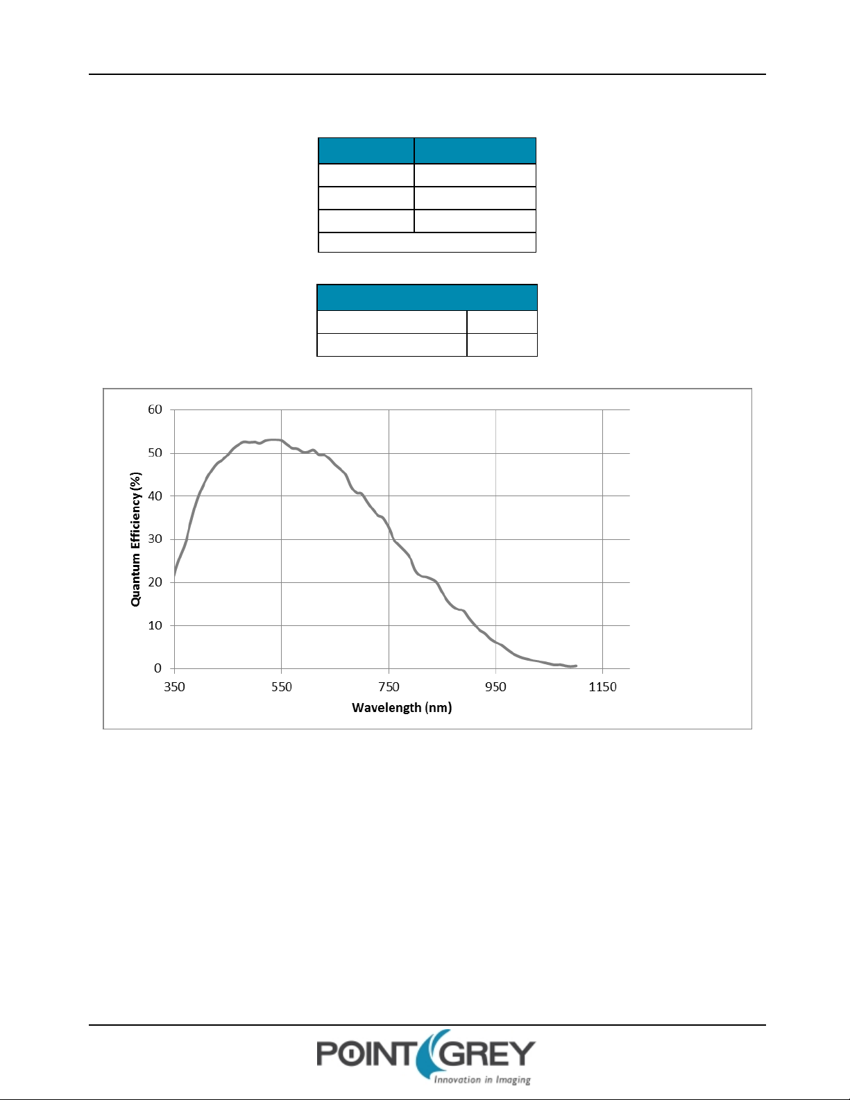
1.1.1 GZL-CL-22C5M(Mono) Imaging Performance
Specification Mode 0
Full Well Depth 12900 e- at zero gain
Dynamic Range 57 dB
Read Noise 18.8 e- at zero gain
Measurements taken at maximum resolution
Quantum Efficiency
Peak QE Wavelength 530 nm
Peak QE Value 56%
Figure 1.1: GZL-CL-22C5 Quantum Efficiency
Revised 10/31/2013
Copyright ©2011-2013 Point Grey Research Inc.
3
Page 11
Point Grey GazelleTech nical Reference 1 Gazelle Specifications
1.1.2 GZL-CL-41C6M(Mono) Imaging Performance
Specification Mode 0
Full Well Depth 11900 e- at zero gain
Dynamic Range 56 dB
Read Noise 18.8 e- at zero gain
Measurements taken at maximum resolution
Quantum Efficiency
Peak QE Wavelength 530 nm
Peak QE Value 53%
Figure 1.2: GZL-CL-41C6 Quantum Efficiency
Revised 10/31/2013
Copyright ©2011-2013 Point Grey Research Inc.
4
Page 12
Point Grey GazelleTech nical Reference 1 Gazelle Specifications
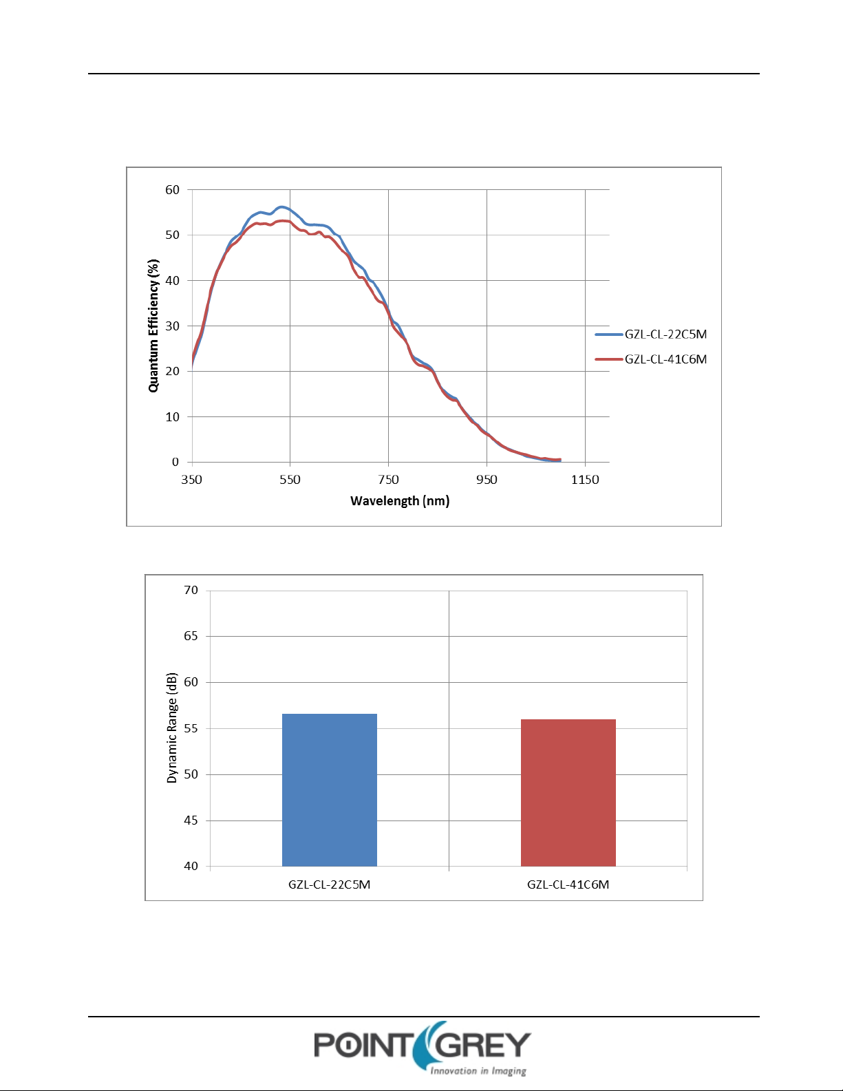
1.1.3 GazelleComparison
Figure 1.3: GZL-CL Mono Quantum Efficiency
Figure 1.4: GZL-CL Mono Dynamic Range
Revised 10/31/2013
Copyright ©2011-2013 Point Grey Research Inc.
5
Page 13
Point Grey GazelleTech nical Reference 1 Gazelle Specifications
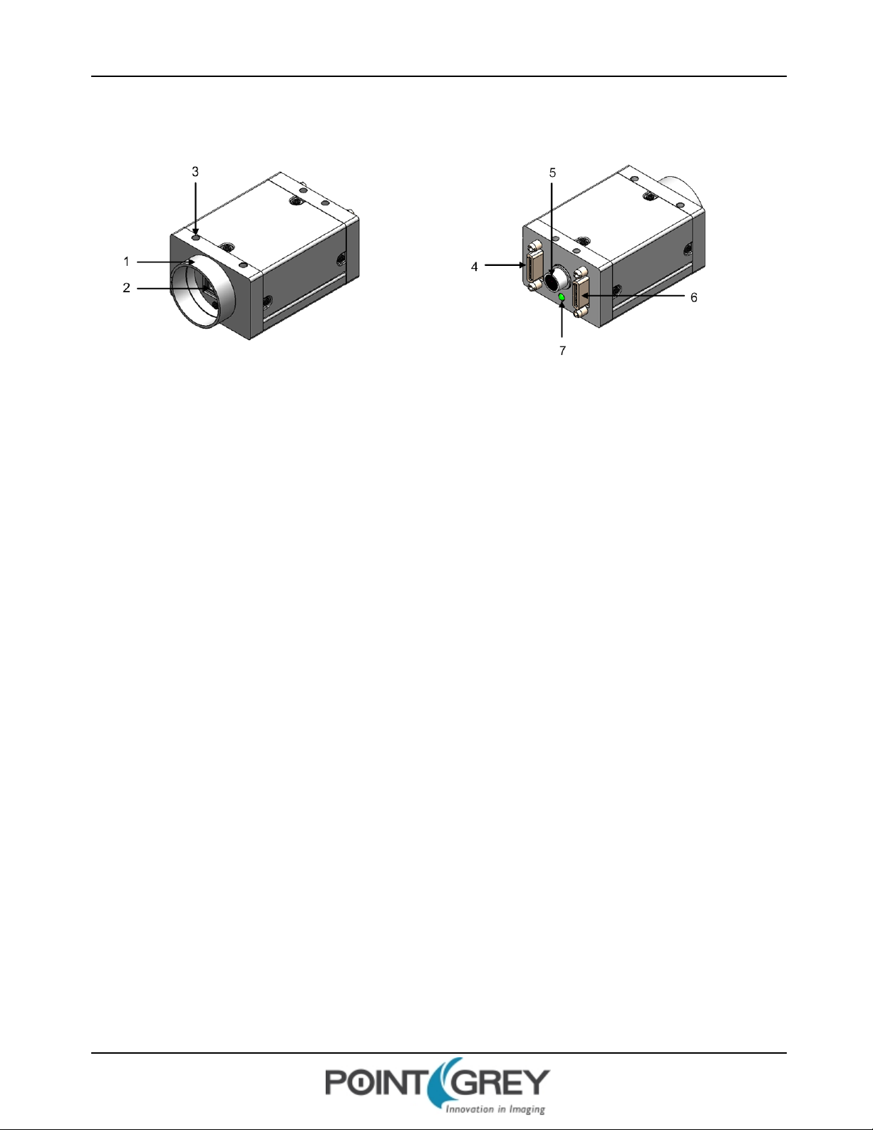
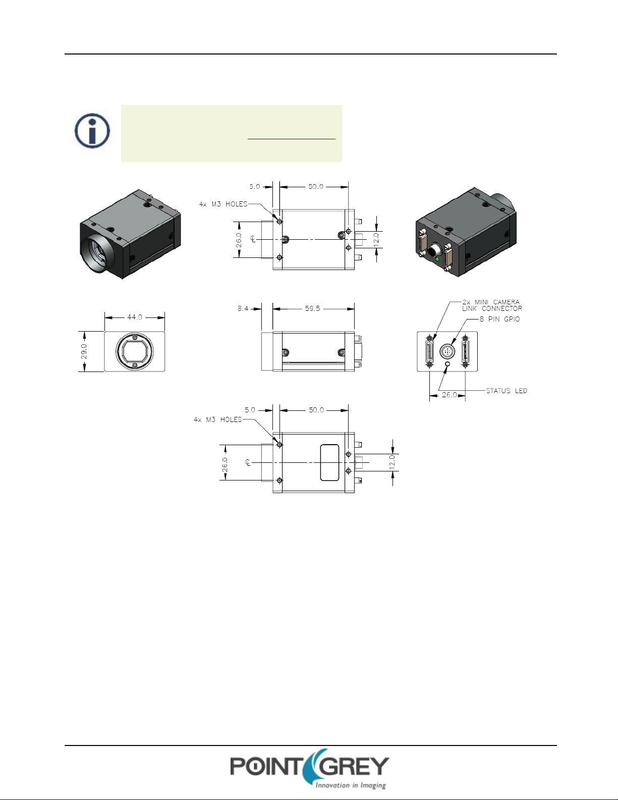
1.2 Physical Description
1. Lens holder (C-mount)
Attach any C-mount lens or other optical
equipment. See Lens Mounting .
4. FULL Camera Link connector
The camera uses a standard 26-pin SDR connector. M2
screwholes are located on either side of the connector
for secure connection to the 26-pin locking Camera Link
cable. Use this connector for the full configuration (with
BASE connector). See Camera Link Connectors.
2. Glass/IR filter system
See Dust Protection .
3. M3 mounting holes
Configuration of M3 mounting holes is the
same on the top and bottom of the camera
case. See Mounting with the Case or
Mounting Bracket.
5. General purpose I/O connector
The 8-pin GPIO connector is used for power, external
triggering, and strobe output. See .
6. BASE Camera Link connector
Use this connector for the base configuration. See
Camera Link Connectors.
7. Status LED
This light indicates the current state of the camera
operation. See Status Indicator LED.
Revised 10/31/2013
Copyright ©2011-2013 Point Grey Research Inc.
6
Page 14
Point Grey GazelleTech nical Reference 1 Gazelle Specifications
1.3 Camera Dimensions
To obtain 3D models, contact support@ptgrey.com.
Revised 10/31/2013
Copyright ©2011-2013 Point Grey Research Inc.
Figure 1.5: Camera Dimensional Diagram
7
Page 15

Point Grey GazelleTech nical Reference 1 Gazelle Specifications
1.4 Tripod Adapter Dimensions
Figure 1.6: Tripod Adapter Dimensional Diagram
1.5 Lens Mounting
Lenses are not included with individual cameras.
Related Knowledge Base Articles
Title Article
Selecting a lens for your camera Knowledge Base Article 345
The lens mount is compatible with C-mount lenses. Correct focus cannot be achieved using a CS-mount lens on a Cmount camera.
Revised 10/31/2013
Copyright ©2011-2013 Point Grey Research Inc.
8
Page 16
Point Grey GazelleTech nical Reference 1 Gazelle Specifications
1.5.1 Back Flange Distance
The Back Flange Distance (BFD) is offset due to the presence of both a 1 mm infrared cutoff (IRC) filter and a 0.55 mm
sensor package window. These two pieces of glass fit between the lens and the sensor image plane. The IRC filter is
installed on color cameras. In monochrome cameras, it is a transparent piece of glass. The sensor package window is
installed by the sensor manufacturer. Both components cause refraction, which requires some offset in flange back
distance to correct.
The resulting C-mount BFDis 18.01 mm.
1.6 Dust Protection
The camera housing is designed to prevent dust from falling directly onto the sensor's protective glass surface. This is
achieved by placing a piece of clear glass (monochrome camera models) or an IR cut-off filter (color models) that sits
above the surface of the sensor's glass. A removable plastic retainer keeps this glass/filter system in place. By increasing
the distance between the imaging surface and the location of the potential dust particles, the likelihood of interference
from the dust (assuming non-collimated light) and the possibility of damage to the sensor during cleaning is reduced.
n Cameras are sealed when they are shipped. To avoid contamination, seals should not
be broken until cameras are ready for assembly at customer's site.
n Use caution when removing the protective glass or filter. Damage to any component of
the optical path voids the Hardware Warranty.
n Removing the protective glass or filter alters the optical path of the camera, and may
result in problems obtaining proper focus with your lens.
Related Knowledge Base Articles
Title Article
Removing the IR filter from a color camera Knowledge Base Article 215
Selecting a lens for your camera Knowledge Base Article 345
1.7 Mounting with the Case or Mounting Bracket
Using the Case
The case is equipped with the following mounting holes:
n Four (4) M3x0.5mm mounting holes on the top of the case
n Four (4) M3x0.5mm mounting holes on the bottom of the case that can be used to attach the camera directly to
a custom mount or to the tripod mounting bracket.
Using the Mounting Bracket
Thetripod mounting bracket is equipped with four (4) M3 mounting holes. For more information, see Tripod Adapter
Dimensions on the previous page.
Revised 10/31/2013
Copyright ©2011-2013 Point Grey Research Inc.
9
Page 17

Point Grey GazelleTech nical Reference 1 Gazelle Specifications
1.8 Analog-to-Digital Converter
All CMOS camera sensors incorporate an on-chip analog to digital converter.
The Gazelle's ADC is configured to a fixed bit output. If the pixel format selected has fewer bits per pixel than the
ADCoutput, the least significant bits are dropped. If the pixel format selected has greater bits per pixel than the ADC
output, the least significant bits are padded with zeros.
A 10-bit conversion produces 1,024 possible values between 0 and 65,472. Image data is left-aligned across a 2-byte
format. The least significant bits are always zero.
The bit depth of the output varies between sensors and can be seen in the table below. Image data is left-aligned across
a 2-byte format. The least significant bits, which are the unused bits, are always zero.
For example, for a 12 bit output, the least significant 4 bits will be zeros in order to fill 2 bytes. E.g. 0xFFF0.
GZL-CL-22C5M-C 10-bit
GZL-CL-41C6M-C 10-bit
Model ADC
Revised 10/31/2013
Copyright ©2011-2013 Point Grey Research Inc.
10
Page 18
Point Grey GazelleTech nical Reference 1 Gazelle Specifications
1.9 Handling Precautions and Camera Care
Do not open the camera housing. Doing so voids the Hardware
Warranty described at the beginning of this manual.
Your Point Grey digital camera is a precisely manufactured device and should be handled with care. Here are some tips
on how to care for the device.
n Avoid electrostatic charging.
n When handling the camera unit, avoid touching the lenses. Fingerprints will affect the quality of the image
produced by the device.
n To clean the lenses, use a standard camera lens cleaning kit or a clean dry cotton cloth. Do not apply excessive
force.
n Extended exposure to bright sunlight, rain, dusty environments, etc. may cause problems with the electronics
and the optics of the system.
n Avoid excessive shaking, dropping or any kind of mishandling of the device.
Related Knowledge Base Articles
Title Article
Solving problems with static electricity Knowledge Base Article 42
Cleaning the imaging surface of your camera Knowledge Base Article 66
1.9.1 Case Temperature and Heat Dissipation
You must provide sufficient heat dissipation to control the internal operating temperature of the camera.
The camera is equipped with an on-board temperature sensor. It allows you to obtain the temperature of the camera
board-level components. The sensor measures the ambient temperature within the case.
Table 1.1: Temperature Sensor Specifications
Accuracy 0.5°C
Range -25°C to +85°C
Resolution 12-bits
As a result of packing the camera electronics into a small space, the outer case of the camera can
become very warm to the touch when running in some modes. This is expected behavior and will not
damage the camera electronics.
Revised 10/31/2013
Copyright ©2011-2013 Point Grey Research Inc.
11
Page 19

Point Grey GazelleTech nical Reference 1 Gazelle Specifications
To reduce heat, use a cooling fan to set up a positive air flow around the camera, taking into consideration the following
precautions:
n Mount the camera on a heat sink, such as a camera mounting bracket, made out of a heat-conductive material
like aluminum.
n Make sure the flow of heat from the camera case to the bracket is not blocked by a non-conductive material like
plastic.
n Make sure the camera has enough open space around it to facilitate the free flow of air.
To access temperature information use:
n Software Instruction Set—Device Temperature command Status Monitoring
Revised 10/31/2013
Copyright ©2011-2013 Point Grey Research Inc.
12
Page 20
Point Grey GazelleTech nical Reference 1 Gazelle Specifications
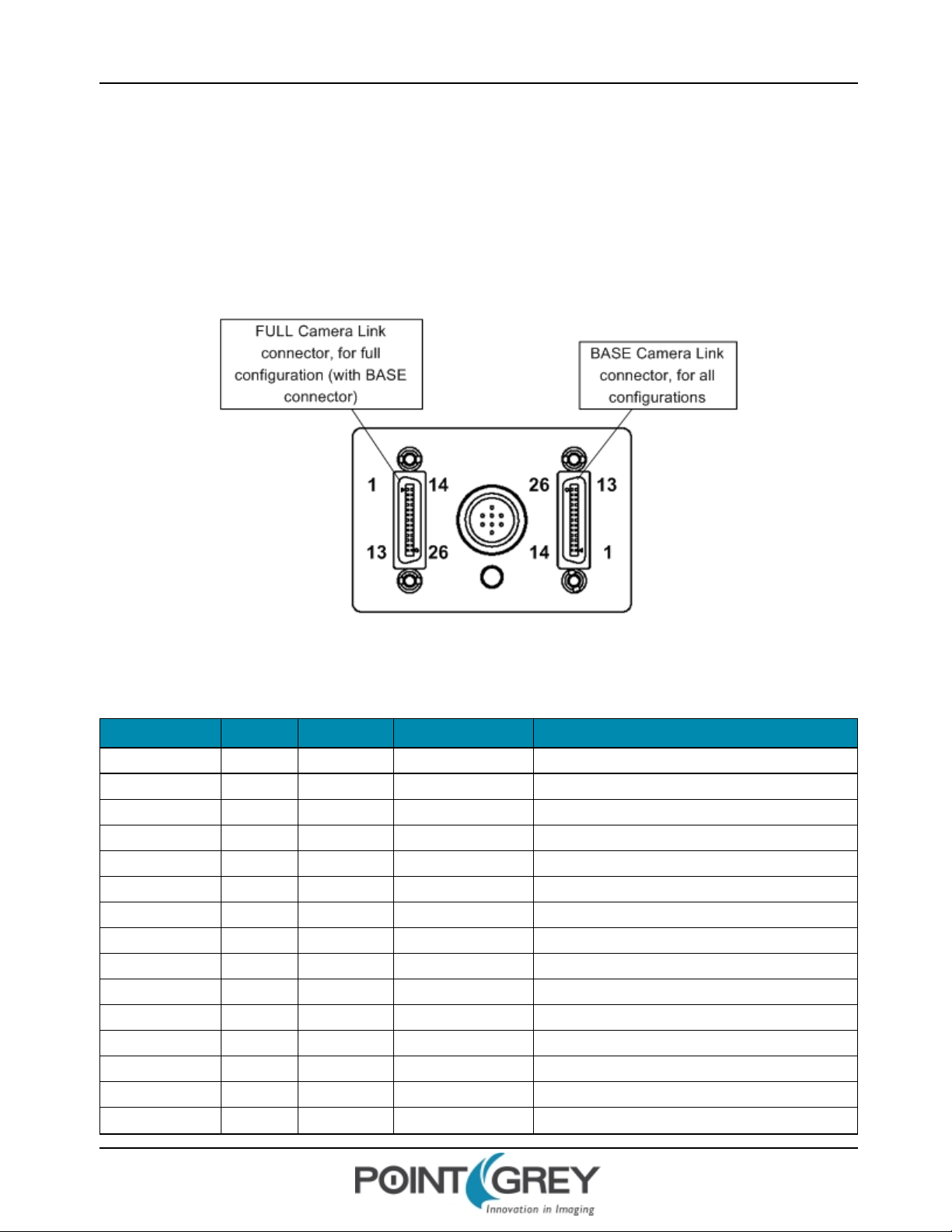
1.10 Camera Interface and Connectors
1.10.1 Camera Link Connectors
The camera is equipped with two 26-pin female 0.05 inch SDR connectors for video data and camera control and
configuration. Pin assignments conform to the Camera Link specification. For reference, pin assignments for both
connectors are provided below. For more information, see Serial Communication.
Figure 1.7: Camera Link connector pin numbering
Table 1.2: BASE Camera Link connector pin assignments
Pin Number Signal Direction Level Description
1 GND In Ground Ground for inner shield of cable
2 XO- Out Camera Link LVDS Data from Camera Link transmitter
3 X1- Out Camera Link LVDS Data from Camera Link transmitter
4 X2- Out Camera Link LVDS Data from Camera Link transmitter
5 XClk- Out Camera Link LVDS Transmit clock from Camera Link transmitter
6 X3- Out Camera Link LVDS Data from Camera Link transmitter
7 SerTC+ In RS-644 LVDS Serial to camera
8 SerTFG- Out RS-644-LVDS Serial to frame grabber
9 CC1- In RS-644-LVDS External trigger
10 CC2+ In RS-644 LVDS External clock (not supported)
11 CC3- In RS-644 LVDS External flash
12 CC4+ In RS-644 LVDS Reserved
13 GND In Ground Ground for inner shield of cable
14 GND In Ground Ground for inner shield of cable
15 XO+ Out Camera Link LVDS Data from Camera Link transmitter
Revised 10/31/2013
Copyright ©2011-2013 Point Grey Research Inc.
13
Page 21
Point Grey GazelleTech nical Reference 1 Gazelle Specifications
Pin Number Signal Direction Level Description
16 X1+ Out Camera Link LVDS Data from Camera Link transmitter
17 X2+ Out Camera Link LVDS Data from Camera Link transmitter
18 XClk+ Out Camera Link LVDS Transmit clock from Camera Link transmitter
19 X3+ Out Camera Link LVDS Data from Camera Link transmitter
20 SerTC- In RS-644 LVDS Serial to camera
21 SerTFG+ Out RS-644 LVDS Serial to frame grabber
22 CC1+ In RS-644 LVDS External trigger
23 CC2- In RS-644 LVDS External clock (not supported)
24 CC3+ In RS-644 LVDS External flash
25 CC4- In RS-644 LVDS Reserved
26 GND In Ground Ground for inner shield of cable
Table 1.3: FULL Camera Link connector pin assignments
Pin Number Signal Direction Level Description
1 GND In Ground Ground for inner shield of cable
2 YO- Out Camera Link LVDS Data from Camera Link transmitter
3 Y1- Out Camera Link LVDS Data from Camera Link transmitter
4 Y2- Out Camera Link LVDS Data from Camera Link transmitter
5 YClk- Out Camera Link LVDS Transmit clock from Camera Link transmitter
6 Y3- Out Camera Link LVDS Data from Camera Link transmitter
7 T+ Connected to T-; not used
8 Z0- Out Camera Link LVDS Data from Camera Link transmitter
9 Z1- Out Camera Link LVDS Data from Camera Link transmitter
10 Z2- Out Camera Link LVDS Data from Camera Link transmitter
11 ZClk- Out Camera Link LVDS Transmit clock from Camera Link transmitter
12 Z3- Out Camera Link LVDS Data from Camera Link transmitter
13 GND In Ground Ground for inner shield of cable
14 GND In Ground Ground for inner shield of cable
15 YO+ Out Camera Link LVDS Data from Camera Link transmitter
16 Y1+ Out Camera Link LVDS Data from Camera Link transmitter
17 Y2+ Out Camera Link LVDS Data from Camera Link transmitter
18 YClk+ Out Camera Link LVDS Transmit clock from Camera Link transmitter
19 Y3+ Out Camera Link LVDS Data from Camera Link transmitter
20 T- Connected to T+; not used
21 Z0+ Out Camera Link LVDS Data from Camera Link transmitter
22 Z1+ Out Camera Link LVDS Data from Camera Link transmitter
23 Z2+ Out Camera Link LVDS Data from Camera Link transmitter
24 ZClk+ Out Camera Link LVDS Transmit clock from Camera Link transmitter
Revised 10/31/2013
Copyright ©2011-2013 Point Grey Research Inc.
14
Page 22

Point Grey GazelleTech nical Reference 1 Gazelle Specifications
Pin Number Signal Direction Level Description
25 Z3+ Out Camera Link LVDS Data from Camera Link transmitter
26 GND In Ground Ground for inner shield of cable
1.10.2 Interface Card
The camera must connect to an interface card. This is sometimes called a host adapter, a bus controller, or a network
interface card (NIC).
To purchase a compatible card from Point Grey, visit the Point Grey Webstore or the Products Accessories page.
1.10.3 Interface Cables
85 MHz-certified cables are required for the Camera Link connection between the camera and the host system. The
maximum supported cable length is 5 meters.
Related Knowledge Base Articles
Which frame grabbers and cables can I use with my Camera Link camera? Knowledge Base Article 359
Title Link
To purchase a recommended cable from Point Grey, visit the Point Grey Webstore or the Products Accessories page.
1.10.4 Frame Grabbers
Point Grey provides camera configuration files (CCFs) for using the following Camera Link frame grabbers with Gazelle
cameras:
n Aval Data APX-3318
n Dalsa Xcelera-CL PX4 Full
n BitFlow Karbon-CL
Related Resources
To find... Go to...
CCFs for download Point Grey downloads page
Related Knowledge Base Articles
Title Article
Which frame grabbers and cables can I use with my Camera Link
camera?
1.10.5 General Purpose Input/Output (GPIO)
Knowledge Base Article 359
The camera has an 8-pin GPIO connector on the back of the case; refer to the diagram below for wire color-coding. The
connector is a Hirose HR25 8 pin connector with part number: HR25-7TR-8SA. The male connector is part number:
HR25-7TP-8P.
Revised 10/31/2013
Copyright ©2011-2013 Point Grey Research Inc.
15
Page 23

Point Grey GazelleTech nical Reference 1 Gazelle Specifications
Diagram Color Pin Function Description
For more information on camera power, see Powering the Camera.
For details on GPIO circuits, see GPIO Electrical Characteristics.
1.10.5.1 GPIO Modes
GPIO Mode 0: Input
When a GPIO pin is put into GPIOMode 0 it is configured to accept external trigger signals. See Serial Communication.
Black 1 I0 Opto-isolated input (default Trigger in)
White 2 O1 Opto-isolated output
Red 3 IO2 Input/Output/serial transmit (TX)
Green 4 IO3 Input/Output/serial receive (RX)
Brown 5 GND Ground for bi-directional IO, V
Blue 6 OPTO_GND Ground for opto-isolated IO pins
Orange 7 V
Yellow 8 +3.3 V Power external circuitry up to 150 mA
EXT
Allows the camera to be powered externally
, +3.3 V pins
EXT
GPIO Mode 1: Output
When a GPIO pin is put into GPIOMode 1 it is configured to send output signals.
Do not connect power to a pin configured as an output (effectively
connecting two outputs to each other). Doing so can cause damage to
camera electronics.
GPIO Mode 2: Asynchronous (External) Trigger
When a GPIO pin is put into GPIO Mode 2, and an external trigger mode is enabled (which disables isochronous data
transmission), the camera can be asynchronously triggered to grab an image by sending a voltage transition to the pin.
See Asynchronous Triggering.
GPIO Mode 3: Strobe
A GPIO pin in GPIO Mode 3 outputs a voltage pulse of fixed delay, either relative to the start of integration (default) or
relative to the time of an asynchronous trigger. A GPIOpin in this mode can be configured to output a variable strobe
pattern. See Programmable Strobe Output.
Revised 10/31/2013
Copyright ©2011-2013 Point Grey Research Inc.
16
Page 24

Point Grey GazelleTech nical Reference 2 Gazelle Installation
2 Gazelle Installation
2.1 Before You Install
2.1.1 Will your system configuration support the camera?
Recommended System Configuration
Operating
System
XP, Vista,
Windows 7
2.1.2 Do you have all the parts you need?
To install your camera you will need the following components:
n Camera Link cable (see Interface Cables)
n 8-pin GPIOcable (see General Purpose Input/Output (GPIO))
n C-mount Lens (see Lens Mounting )
n Tripod adapter (optional) (see Mounting with the Case or Mounting Bracket)
n Interface card (see Interface Card)
CPU RAM Video Ports
2.4 GHz (or
equivalent)
512MBNVIDIAGeForce6 or later; 128 MB RAM
or more
Camera Link PCIe card with Full CL
interface
Point Grey sells a number of the additional parts required for installation. To purchase, visit the Point Grey Webstore or
the Products Accessories page.
2.1.3 Do you have a downloads account?
The Point Grey downloads page has many resources to help you operate your camera effectively, including:
n Software, including CCFs (required for installation)
n Firmware updates and release notes
n Dimensional drawings and CADmodels
n Documentation
To access the downloads resources you must have a downloads account.
1. Go to the Point Grey downloads page.
2. Under Register (New Users), complete the form, then click Submit.
After you submit your registration, you will receive an email with instructions on how to activate your account.
Revised 10/31/2013
Copyright ©2011-2013 Point Grey Research Inc.
17
Page 25

Point Grey GazelleTech nical Reference 2 Gazelle Installation
2.2 Installing Your Interface Card and Software
1. Install your Interface Card
Ensure the card is installed per the manufacturer's instructions.
Connect the internal IDE or SATApower connector on the card to the computer power
supply.
Open the Windows Device Manager. Ensure the card is properly installed under the manufacturer's name or, in some
cases, Multifunction Adaptors. An exclamation point (!) next to the card indicates the driver has not yet been installed.
2. Enable the driver for the card
If not already done so as part of the card installation, enable the driver for the card as per the manufacturer's
instructions.
3. Install the Camera Configuration File for your Frame Grabber
a. Login to the Point Grey downloads page.
b. Select your Gazelle from the drop-down lists and click the Search button.
c. Click on the Software search results to expand the list.
d. Click on Gazelle Camera Configuration Files to begin the download.
e. From the download location, extract the zip files to a directory location of your choice.
Revised 10/31/2013
Copyright ©2011-2013 Point Grey Research Inc.
18
Page 26

Point Grey GazelleTech nical Reference 2 Gazelle Installation
2.3 Installing Your Camera
1. Install the Tripod Mounting Bracket (optional)
The ASA and ISO-compliant tripod mounting bracket attaches to the camera using the included
metal screws.
2. Attach a Lens
Unscrew the dust cap from the C-mount lens holder to install a lens.
3. Connect the interface Card and Cable to the Camera
Plug the interface cable into the host controller card and the camera. The cable jack screws can be used for a secure
connection.
For Base 2-tap configuration, use base connector. For Full 8-tap configuration, use both base and full connectors (two
cables are required). Connectors are labelled on the camera.
4. Plug in the GPIO connector
GPIOis used for power, trigger, serial input output, and strobe.
The wiring harness must be compatible with a Hirose HR25 8-pin female GPIOconnector.
5. Confirm Successful Installation
To operate the camera, start the serial interface tool for your frame grabber and reference the configuration files
downloaded in Step 3 of Installing your Interface Card and Software. Control the camera using the software instruction
set described in the Technical Reference Manual.
2.4 Controlling the Camera
The user can monitor or control features of the camera using a command set developed by Point Grey. These
commands are used with the serial interface tool provided by your Camera Link frame grabber, and control the camera
via a frame grabber-specific camera configuration file (CCF) that is downloaded during the camera installation process.
For more information about CCFs, see Frame Grabbers.
Commands are introduced in this manual with the features they control. In some cases, examples of common usage are
also provided. A complete list of commands is provided in Software Instruction Set.
Commands return an error when parameters are outside of allowable values. All errors begin with the string Err:
Revised 10/31/2013
Copyright ©2011-2013 Point Grey Research Inc.
19
Page 27

Point Grey GazelleTech nical Reference 2 Gazelle Installation
2.4.1 User Configuration Sets
The camera can save and restore settings and imaging parameters via on-board configuration sets, also known as
memory channels. This is useful for saving default power-up settings, such as gain, shutter, video format and frame rate,
and others that are different from the factory defaults.
Configuration set 0 stores the factory default settings. Two additional sets are provided for custom default settings.
The following property settings are saved in configuration sets:
Table 2.1: User configuration set properties
Number of taps (see Setting the Video Format and
Frame Rate)
Sensor Input Clock speed Strobe activation (see Programmable Strobe Output)
Gain(analog and digital) Chunk Data and checksum embedding
Exposure Blemish Pixel Artifacts correction on/off
Black Level Test Pattern mode
Trigger source (see Triggering off the GPIO Height and vertical offset of all ROIs (seeSpecifying Regions of Interest)
Trigger mode (see Asynchronous Triggering) Width and horizontal offset of R OIs (seeSpecifying Regions of Interest)
Trigger Delay Sensor Mode Pixel Binning
Trigger activation phase (see Trigger Polarity) Image Flip/Mirror
Strobe mode (see Programmable Strobe Output)
Strobe delay (see Programmable Strobe Output)
User Configuration Sets
Name Description Write
Saves the camera's current configuration to
User Set Save
User Set Load Loads a configuration set
User Set Current Gets the currently-loaded configuration set memcurr
one of the three available user-configuration
sets
memsave value
value is 1 or 2
memload value
value is 0 (default), 1, or 2
Revised 10/31/2013
Copyright ©2011-2013 Point Grey Research Inc.
20
Page 28

Point Grey GazelleTech nical Reference 3 General Gazelle Operation
3 General Gazelle Operation
3.1 Powering the Camera
The power consumption specification is: 12 V +/- 10%, 6 W.
Power must be provided through the GPIO interface. For more information, see General Purpose Input/Output (GPIO).
Point Grey sells a 12 V wall-mount power supply equipped with a HR25 8-pin GPIO wiring harness for connecting to the
camera. For more information, see the miscellaneous product accessories page on the Point Grey website.
The camera does not transmit images for the first 100 ms after power- up. The auto-exposure and auto-white balance
algorithms do not run while the camera is powered down. It may therefore take several (n) images to get a satisfactory
image, where n is undefined.
When the camera is power cycled (power disengaged then re-engaged), the camera reverts to its default factory
settings, or if applicable, the last saved memory channel. For more information, see User Configuration Sets.
3.2 Camera Error and Status Monitoring
3.2.1 Camera Initialization
For information about power-up default settings, refer to the Gazelle Specifications. For information about powering-up
to a user-defined configuration set, see User Configuration Sets.
Device Reset
Name Description Read Write
Device Reset Resets Device to Power Up State dr
Indicates if initialization is complete
Initialization
0=Still in initialization
1=Complete
3.2.2 General Status Monitoring
Use the following parameters to monitor the status of the camera.
Uptime Status—This reports the time, in seconds, since the camera was initialized during a hard power-up. This is
different from powering up the camera, which will not reset this time.
Voltage—This allows the user to access and monitor the input as well as several of the internal voltages of the cameras.
Current—This allows the user to access and monitor the current consumption of the camera.
init
Temperature—Allows the user to get the temperature of the camera board-level components. For cameras housed in
a case, it is the ambient temperature within the case. For more information about camera temperature, see Case
Temperature and Heat Dissipation.
Revised 10/31/2013
Copyright ©2011-2013 Point Grey Research Inc.
21
Page 29

Point Grey GazelleTech nical Reference 3 General Gazelle Operation
Status Monitoring
Name Description Read Write
Voltage Status Returns the internal and external voltage, in volts vstat
Current Status Returns the electrical current, in amperes cstat
Uptime Status
Device Clock
Frequency
Device
Temperature
Returns the time since the camera was last initialized, in
hours:minutes:seconds
Returns the frequency of the sensor input Clock, in hertz dcf
Returns the ambient temperature inside the camera case,
in degrees Celsius
3.2.3 Device Information
Use the following to obtain information about the camera.
Device Information
Name Description Read
Device Vendor Name Returns the Vendor Name dvn
Device Model Name Returns the Model Name dvm
Device Firmware Version Returns the Firmware Version dfv
Device Firmware Build Date Returns the Firmware build date dbd
Device Hardware Version Returns the hardware versions of the PCBs in the camera dhv
Sensor Hardware Version
Device ID Returns the Serial Number did
Returns the sensor model of the camera
0170FFFEh = CMOSISCMV4000
0180FFFEh = CMOSISCMV2000
ustat
dcf value
value can be 40, 35, 30, 20, or 10MHz
for 8-tap mode
10 MHz for 2-tap mode
dt
shv
Revised 10/31/2013
Copyright ©2011-2013 Point Grey Research Inc.
22
Page 30

Point Grey GazelleTech nical Reference 3 General Gazelle Operation
Name Description Read
Gets the following camera information:
Camera Model
Camera Serial Number
Firmware Version
Firmware Build Date
Baud Rate
Analog Gain
Digital Gain
Trigger source
Trigger Polarity
Trigger Mode
Trigger Delay
Strobe width
Strobe Mode
Strobe Delay
Device Information
Strobe Activation
ROIs
Reverse Image Status
Defect Pixel Correction status
Current User Set
Voltage Status
Current Status
Uptime Status
Width
Height
OffsetX
OffsetY
Number of Taps
Input Clock
Exposure
Black Level
dump
3.3 Non-Volatile Flash Memory
The camera has 4 MB non- volatile memory for users to store data. Data must be written to individual pages in 528-byte
data chunks.
Related Knowledge Base Articles
Title Article
Storing data in on-camera flash memory Knowledge Base Article 341
Revised 10/31/2013
Copyright ©2011-2013 Point Grey Research Inc.
23
Page 31

Point Grey GazelleTech nical Reference 3 General Gazelle Operation
Non-Volatile Flash Memory
Name Description Read Write
Returns the following in
order:
Flash Memory Size
Flash Memory
Write
Flash Memory
Read
Flash Memory
Clear Page
Flash Memory
Clear All
Total size of flash memory
Number of pages
Page size
Writes a page to the flash
memory
Reads a page from the flash
memory
Clears a page of the flash
memory
Clears all the flash memory dfclear
dfr page_number
page_number can be
from 0 to 8191
dfi
dfw page_number num_bytes ASCII_string
page_number can be from 0 to 8191
num_bytes can e from 0 to 527
If the size of ASCII_string is more than 528 bytes,
it is cut to 528 to fit the page size
dfw page_number 0 0
page_number can be from 0 to 8191
3.4 Camera Firmware
Firmware is programming that is inserted into the programmable read-only memory (programmable ROM) of most
Point Grey cameras. Firmware is created and tested like software. When ready, it can be distributed like other software
and installed in the programmable read-only memory by the user.
The latest firmware versions often include significant bug fixes and feature enhancements. To determine the changes
made in a specific firmware version, consult the Release Notes.
Firmware is identified by a version number, a build date, and a description.
Related Knowledge Base Articles
Title Article
PGR software and firmware version numbering
scheme/standards
Determining the firmware version used by a PGR camera Knowledge Base Article 94
Should I upgrade my camera firmware or software? Knowledge Base Article 225
3.4.1 Upgrading Camera Firmware
Camera firmware can be upgraded or downgraded to later or earlier versions using
Before upgrading firmware:
Knowledge Base Article 96
n Install the SDK, downloadable from the Point Grey downloads site.
n Download the firmware file from the Point Grey downloads site.
Revised 10/31/2013
Copyright ©2011-2013 Point Grey Research Inc.
24
Page 32

Point Grey GazelleTech nical Reference 3 General Gazelle Operation
To upgrade the firmware:
1. Start Menu-->All Programs-->FlyCapture2 SDK-->Utilities-->UpdatorGUI
2. Select the camera from the list at the top.
3. Click Open to select the firmware file.
4. Click Update.
Do not disconnect the camera during the update process.
Firmware Information
Name Description Read Write
Device Firmware Version Returns the Firmware Version dfv
Device Firmware Build Date Returns the Firmware build date dbd
Update Mode Puts the camera into firmware update mode update
Revised 10/31/2013
Copyright ©2011-2013 Point Grey Research Inc.
25
Page 33

Point Grey GazelleTech nical Reference 4 VideoData Output
4 Video Data Output
4.1 GZL-CL-22C5 Video Data Output
# Taps Bit Depth Max Size (HxV)
8 8 2048x1088 281 319 630 1231 2347
2 10 2048x1088 71 80 160 319 630
4.2 GZL-CL-41C6 Video Data Output
# Taps Bit Depth Max Size (HxV)
Max
Size
Max
Size
1600 x
1200
Maximum Frame Rate at
1280 x 960 640 x 480 320 x 240 160 x 120
Maximum Frame Rate at
1280 x
960
640 x 480 320 x 240 160 x 120
8 8 2048x2048 149 253 315 618 1183 2183
2 10 2048x2048 37 64 80 160 318 630
Revised 10/31/2013
Copyright ©2011-2013 Point Grey Research Inc.
26
Page 34

Point Grey GazelleTech nical Reference 4 VideoData Output
4.3 Setting the Video Format and Frame Rate
The number of Camera Link taps for video output dictates the data format and frame rate in which the camera operates,
per the tables above. The number of Camera Link taps can be changed dynamically without power-cycling the camera.
Setting Video Format
Name Description Read Write
Gets or sets the video format. Can be
Video Format
set to 2-tap, 8-tap, 8-tap 10-bit, or
bin2x2. (2x binning is only available in
base 2-tap mode)
4.3.1 Sensor Mode Pixel Binning
When operating in base 2-tap mode, the camera can implement 2x2 pixel binning, which occurs digitally after sensor
readout, on the FPGA of the camera. In this configuration, the values of two adjacent pixels are aggregated and
averaged, both vertically and horizontally, resulting in a resolution that is both half in width and half in height of the
original video output. Pixel binning can be implemented in conjunction with regions of interest. See Specifying Regions
of Interest.
smod
smod value
value is 2tap, 8tap, 8tap10bit, bin2x2
The primary benefit of pixel binning is an increase in frame rate in 2-tap mode. When binning is implemented, the
sensor input clock can run up to twice as fast as in non-binning mode, resulting in a frame rate also up to twice as fast.
Because pixel values are averaged after aggregation, there is no significant increase in image intensity.
Sensor Mode Pixel Binning
Name Description Read Write
Sensor Mode (Pixel
Binning mode)
Gets or sets the sensor mode to 2x binning (only
available in base 2-tap mode)
4.3.2 Specifying 8-Tap 10-Bit Output
Unless identified as 8-tap 10-bit, references to 8-tap throughout this document mean 8-tap 8-bit.
The camera can output 10 bits/pixel in full 8-tap configuration. This mode is not supported by the Camera Link standard
and requires users to implement custom software to decode data on the PC for outputting images.
In this mode, four contiguous horizontal pixels contain the eight most significant bits (MSB) of their respective pixels.
Every fifth pixel contains the two least significant bits (LSB) of the previous four pixels, effectively increasing image
output width by 25%. The bit format of every fifth pixel is as follows:
smod smod bin2x2
Revised 10/31/2013
Copyright ©2011-2013 Point Grey Research Inc.
Bits of every 5th pixel Description
0 - 1 LSBs of 4th pixel
2 - 3 LSBs of 3rd pixel
4 - 5 LSBs of 2nd pixel
6 - 7 LSBs of 1st pixel
27
Page 35

Point Grey GazelleTech nical Reference 4 VideoData Output
To output 8-tap 10-bit data, you must increase image width on the frame grabber by 25%. Assuming no
ROI is specified, width should be increased to 2560. Frame grabber output will appear corrupted unless
user-defined post-processing is performed on the PC. After processing, image width at full resolution
should be 2048.
Video Format 8-tap 10-bit
Name Description Read Write
Video Format (8-tap 10bit mode)
Gets or sets the video format to 8-tap 10-bit smod smod 8tap10bit
Revised 10/31/2013
Copyright ©2011-2013 Point Grey Research Inc.
28
Page 36

Point Grey GazelleTech nical Reference 4 VideoData Output
4.4 Specifying Regions of Interest
You can specify subsets of the sensor pixel array, or 'regions of interest (ROIs),' for transmitting images. Regions of
interest allow you to limit the amount of image data that is sampled and transmitted, and may increase frame rate.
When specifying regions of interest, keep in mind the following:
n Vertical offset and height are configurable in increments of one pixel row. Horizontal offset and width are
configurable in multiples of eight pixel columns.
n Reducing the number of rows is performed on the image sensor, prior to image readout. Reducing image width
is performed on the FPGA of the camera. As a result, a frame rate increase may be achieved by reducing image
height. No frame rate increase is achieved by reducing image width.
n Vertical and horizontal offsets are measured from pixel (0,0) in the image array.
n Dynamically setting or changing ROI configuration does not require stopping and re-starting image acquisition, or
produce any latency in frame rate.
n To maximize frame rate, exposure adjusts dynamically when ROIs are set or changed. For more information
about exposure, see Exposure.
n ROI settings are saved in user configuration sets. For more information, see User Configuration Sets.
n ROI information can be saved in chunk data. For more information, see Chunk Data.
4.4.1 Specifying Multiple ROIs
The camera supports up to eight ROIs within the larger pixel array. Multiple ROIs have different vertical offsets, but only
one width and horizontal offset can be set for all ROIs. The camera joins multiple ROIs to form a single image, which is
transmitted to the frame grabber in a single frame readout cycle. Imaging parameters, such as exposure, gain and black
level, are applied equally to all ROIs.
4.4.2 Calculating Frame Rate
Using the following formulas, you can calculate frames per second based on Sensor Input Clock speed and image height.
Due to the Camera Link standard for processing Frame Valid and Line Valid bits of
LVDS data channels,actual frame rates may be slower than calculated frame rates.
The formula for calculating frame rate is:
Frame Rate = 1 / (Frame Overhead Time +Readout Time)
GZL-CL-41C6
Sensor Input Clock (MHz) FOT (µs) Readout Time (µs)
40 70.95 (129 / 40) x height
35 81.08 (129 / 35) x height
30 94.60 (129 / 30) x height
20 141.90 (129 / 20) x height
10 38.70 (129 / 10) x height
GZL-CL-41C6 Example:
For a camera operating at 40 MHz with an image size of 2048 x 2048, the frame rate would be:
Revised 10/31/2013
Copyright ©2011-2013 Point Grey Research Inc.
29
Page 37

Point Grey GazelleTech nical Reference 4 VideoData Output
Frame rate = 1 / (FOT+Readout Time)
= 1 / [70.95 +((129/40) x 2048)]
= 1 / [70.95 + (3.225 x 2048)]
= 1 / [70.95 + 6604.8]
= 1 / 6675.75µs
= 1 / 0.00667575 seconds
= 149.79 FPS
GZL-CL-22C5
Sensor Input Clock
(MHz)
40 38.70 (129 / 40) x height
35 44.23 (129 / 35) x height
30 51.60 (129 / 30) x height
20 77.40 (129 / 20) x height
10 38.70 (129 / 10) x height
FOT
(µs)
Readout Time
(µs)
GZL-CL-22C5 Example:
For a camera operating at 40 MHz with an image size of 2048 x 1088, the frame rate would be:
4.4.3 Creating ROIs
Use the following commands when creating ROIs.
Regions of Interest (ROI)
Name Description Read Write
Width
OffsetY, Height
Frame rate = 1 / (FOT+Readout Time)
= 1 / [38.70 +((129/40) x 1088)]
= 1 / [38.70 + (3.225 x 1088)]
= 1 / [38.70 + 3508.8]
= 1 / 3547.5µs
= 1 / 0.0035475 seconds
= 281.89 FPS
Gets or sets the image width
(Returns zero if no ROIs are present)
Width must be specified before
horizontal offset.
Gets or sets the vertical offset and
height of current ROIs. (Returns zero
if no ROIs are present)
To specify more than one ROI, use
multiple setroi commands. R OI_
number and y-offset must vary
between ROIs
w
getroi
w value
value is in pixel columns and is measured from the
specified horizontal offset; it must be a multiple of 8
setroi ROI_number y_offset height
ROI_number can be from 0 to 7, specifying one of
eight allowable ROIs
y_offset is the starting row of the ROI on the y-axis,
measure from pixel row 0 at the top of the image
height specifies how many rows of pixels are
sampled, beginning from the y-offset
Revised 10/31/2013
Copyright ©2011-2013 Point Grey Research Inc.
30
Page 38

Point Grey GazelleTech nical Reference 4 VideoData Output
Name Description Read Write
Gets or sets the horizontal offset of
OffsetX
Sensor Width
Sensor Height
the image from the left side of the
pixel array. (Returns zero if no ROIs
are present)
The combination of horizontal offset
and width must not exceed sensor
width.
Returns the total width of the sensor,
in pixels
Returns the total height of the
sensor, in pixels
Removes an ROI or returns the
camera to non-ROI operation.
ox
sw
sh
ox offset
offset is the starting column of the ROI on the x-axis,
measured from pixel column 0 at the left of the
image; it must be a multiple of 8
Removing a subset of ROIs results in
Remove ROI
the camera sampling and
transmitting any remaining ROIs. If
all ROIs are removed, the camera
stops using R OIs and returns to
sampling and transmitting the entire
pixel array
Regions of interest must be removed, then re-created, when changing video output format, including
number of taps (see Setting the Video Format and Frame Rate) or between binning and non-binning (see
Sensor Mode Pixel Binning), or when changing ROI height.
Best practice: If creating a single ROI, specify ROI_ number = 0. If creating multiple ROIs, number them sequentially
from the top-most ROI, beginning with ROI_number =0.
4.4.4 Example: Specifying Regions of Interest
The figure below shows three regions of interest specified within the 2048 x 2048 pixel array of the GZL-CL-41C6: ROI_
0, ROI_1 and ROI_2. ROI_0 is offset vertically by 300 pixels, and is 374 pixels in height. ROI_1 is offset vertically by 874
pixels and is 300 pixels in height. ROI_2 is offset vertically by 1374 pixels and is 374 pixels in height. The ROIs are offset
horizontally by 648 pixels, and are 752 pixels wide.
rstroi ROI_number
ROI_number is a previously set ROI using the setroi
command. Removing an ROI does not affect the
ROI_number value of any remaining ROIs
Revised 10/31/2013
Copyright ©2011-2013 Point Grey Research Inc.
31
Page 39

Point Grey GazelleTech nical Reference 4 VideoData Output
Figure 4.1: Example ROI configuration on GZL-CL-41C6
The following are the commands for achieving this ROI configuration:
setroi 0 300 374
setroi 1 874 300
setroi 2 1374 374
w 752
ox 648
Revised 10/31/2013
Copyright ©2011-2013 Point Grey Research Inc.
32
Page 40

Point Grey GazelleTech nical Reference 5 Image Acquisition
5 Image Acquisition
5.1 Free-Running Acquisition
When image capture is not controlled by a triggering mechanism, the camera captures and transmits image data
continuously, based on the specified frame rate. For information, see Video Data Output. When Exposure is increased
beyond what the specified frame rate can sustain, the frame rate is lowered dynamically.
Image Acquisition
Name Description Read Write
Acquisition Start Starts Image Acquisition astart
Acquisition Stop Stops Image Acquisition astop
5.2 Asynchronous Triggering
The camera supports asynchronous triggering, which allows the start of exposure (shutter) to be initiated by an external
electrical source (or hardware trigger) or from an internal software mechanism (software trigger).
External triggers can be sourced through one of the RS- 644 LVDS Camera Control (CC) signals on the Camera Link
connectors, or a GPIO pin. For information about the Camera Link connectors, see Camera Link Connectors. For
information about the GPIO interface, see .
Gazelle Supported Trigger Modes
Model Mode
All Single-Shot Trigger Mode
All Bulb Shutter Trigger Mode
GZL-CL-22C5 and GZL-CL- 41C6 models implement different exposure timing mechanisms between freerunning and asynchronous trigger modes. As a result, images may appear over-exposed when switching
to trigger mode. To fix, lower the gain or exposure settings. For more information, see Gain or Exposure.
Additionally, achievable frame rates may decrease. To fix, lower the exposure setting. To maximize
frame rate when operating these models in trigger mode, we recommend raw exposure values of 100
or less.
To access trigger modes:
n Software Instruction Set—Acquisition Control
Revised 10/31/2013
Copyright ©2011-2013 Point Grey Research Inc.
33
Page 41

Point Grey GazelleTech nical Reference 5 Image Acquisition
Triggering
Name Description Read Write
Trigger
Source
Trigger
Mode
Trigger
Software
Gets or sets the source from which to
accept an incoming trigger
Gets or sets the trigger acquisition
mode
Fires a software trigger trgsoft
5.2.1 Triggering off the GPIO
This example puts the camera into synchronized exposure mode by starting exposure from the falling edge of a trigger
that originates from the camera's opto-isolated GPIO pin (GPIO0). Single-shot mode is specified, which means exposure
lasts for the duration to which it is set, in this case a raw value of 10, or 10.32 μs (Full 8-tap configuration, 40 MHz input
clock):
trsrc
trm
trsrc source
source may be:
soft—Software trigger
line1—Camera Control 1 (CC1)
line2—Camera Control 2 (CC2)
line3—Camera Control 3 (CC3)
line4—Camera Control 4 (CC4)
GPIO0—Opto-isolated GPIO input pin
trm mode
mode is single, bulb, freerun, or none.
(Both freerun and none put the camera in a free running
state, but freerun may limit maximum frame rate. See
Horizontal Line Artifact for more information.)
trsrc GPIO0
eraw 10
tra fe
trm single
5.2.2 Software triggering
This example puts the camera into synchronized exposure mode by starting exposure from a software trigger. Singleshot mode is specified, with a raw exposure value of 100, or 393.45 μs (full configuration, 40 MHz input clock). The
example finishes by invoking a software trigger, which results in one frame capture.
trsrc soft
eraw 100
trm single
trgsoft
Revised 10/31/2013
Copyright ©2011-2013 Point Grey Research Inc.
34
Page 42

Point Grey GazelleTech nical Reference 5 Image Acquisition
5.2.3 Maximum Frame Rates When Triggering
The following are the camera's maximum achievable frame rates in asynchronous trigger mode, full 8-tap configuration,
and exposure set to the minimum allowable value when triggering (eraw = 5).
Table 5.1: Maximum Frame Rates in Trigger Mode
Camera Trigger Mode Maximum Frames per Second
GZL-CL-22C5
GZL-CL-41C6
If exposure is set to higher than image readout rate * image height, frame rate decreases dynamically. To determine
readout rate, see Asynchronous Triggering. For information about setting exposure, see Exposure.
Single shot 265
Bulb shutter 266
Single shot 142
Bulb shutter 142
Revised 10/31/2013
Copyright ©2011-2013 Point Grey Research Inc.
35
Page 43

Point Grey GazelleTech nical Reference 5 Image Acquisition
5.2.4 Trigger Delay
You can specify a delay from when a trigger signal is detected by the camera to when the trigger actually fires and
initiates image acquisition.
To convert from raw values to seconds, use one of the following formulas, depending on current number of taps for
output (see Setting the Video Format and Frame Rate) and Sensor Input Clock speed.
n Full 8-tap configuration:
40 MHz (default)
((2^12 * raw_value ) / 40e6 ) + 0.00007095
30 MHz
((2^12 * raw_value ) / 30e6 ) + 0.0000946
20 MHz
((2^12 * raw_value ) / 20e6 ) + 0.0001419
10 MHz
((2^12 * raw_value ) / 10e6 ) + 0.0002838
n Base 2-tap configuration:
((2^12 * raw_value ) / 10e6 ) + 0.0000903
Trigger Delay
Name Description Read Write
Gets or sets the delay from when the trigger
Trigger Delay Raw
Trigger Delay Minimum
Trigger Delay
Maximum
signal is detected to when the trigger fires and
initiates image acquisition
Gets the minimum image acquisition delay
available in the current video mode
Gets the maximum image acquisition delay
available in the current video mode
trdraw
trdraw gmin
trdraw gmax
trdraw value
value is in raw (non-absolute)
terms
Revised 10/31/2013
Copyright ©2011-2013 Point Grey Research Inc.
36
Page 44

Point Grey GazelleTech nical Reference 5 Image Acquisition
5.2.5 Trigger Polarity
You can specify the rising or falling edge of the trigger phase that activates image acquisition.
Trigger Polarity
Name Description Read Write
Trigger Activation
Gets or sets the trigger phase that
activates image acquisition
5.2.6 Single-Shot Trigger Mode
In single-shot trigger mode, the camera starts exposure of the incoming light from external trigger input falling/rising
edge. Exposure time is user-configurable (see Exposure.) The camera can be triggered in this mode using the Camera
Link camera control lines, the opto-isolated GPIO pin, or internally (software trigger). For information about maximum
frame rates while triggering, see Maximum Frame Rates When Triggering.
To configure trigger delay, see Trigger Delay. If no additional delay is explicitly configured, the delay between the trigger
signal and exposure is 45 ns.
tra
tra phase
phase is re (rising edge) or fe (falling edge)
Figure 5.1: Single-Shot Trigger Timing
Values for Frame Overhead Time and Readout Rate vary by current Sensor Input Clock speed and Video Data
Outputmode , as follows:
Revised 10/31/2013
Copyright ©2011-2013 Point Grey Research Inc.
37
Page 45

Point Grey GazelleTech nical Reference 5 Image Acquisition
Full 8-tap configuration
Sensor Input Clock Speed (MHz) Frame Overhead Time (µs) Readout Rate (µs/line)
40 70.95 3.2
30 94.60 4.27
20 141.9 6.4
10 38.7 12.8
Base 2-tap configuration
Sensor Input Clock Speed (MHz) Frame Overhead Time (µs) Readout Rate (µs/line)
20 (binning mode) 141.9 6.4
10 (non-binning mode) 38.7 12.8
Revised 10/31/2013
Copyright ©2011-2013 Point Grey Research Inc.
38
Page 46

Point Grey GazelleTech nical Reference 5 Image Acquisition
5.2.7 Bulb Shutter Trigger Mode
In bulb shutter mode, the camera starts exposure from the external trigger edge. Exposure time is equal to the low
state time of the external trigger input. For information about maximum frame rates while triggering, see Maximum
Frame Rates When Triggering.
To configure trigger delay, see Trigger Delay. If no additional delay is explicitly configured, the delay between the trigger
signal and exposure is 45 ns.
Figure 5.2: Bulb Shutter Trigger Timing
Values for Frame Overhead Time and Readout Rate vary by current Sensor Input Clock speed and Video Data
Outputmode , as follows:
Full 8-tap configuration
Sensor Input Clock Speed (MHz) Frame Overhead Time (µs) Readout Rate (µs/line)
40 70.95 3.2
30 94.60 4.27
20 141.9 6.4
10 38.7 12.8
Base 2-tap configuration
Sensor Input Clock Speed (MHz) Frame Overhead Time (µs) Readout Rate (µs/line)
20 (binning mode) 141.9 6.4
10 (non-binning mode) 38.7 12.8
Revised 10/31/2013
Copyright ©2011-2013 Point Grey Research Inc.
39
Page 47

Point Grey GazelleTech nical Reference 5 Image Acquisition
5.2.8 Minimum Trigger Pulse Length
A digital signal debouncer helps to ensure that the camera does not respond to spurious electrical signals that are
shorter than 16 ticks of the current Sensor Input Clock setting. This safeguard results in a minimum 16-tick delay before
the camera responds to a trigger signal.
Revised 10/31/2013
Copyright ©2011-2013 Point Grey Research Inc.
40
Page 48

Point Grey GazelleTech nical Reference 5 Image Acquisition
5.3 Programmable Strobe Output
The camera is capable of outputting a strobe pulse off select GPIO pins that are configured as outputs. The start of the
strobe can be offset from either the start of exposure (free-running mode) or time of incoming trigger (external trigger
mode). By default, a pin that is configured as a strobe output will output a pulse each time the camera begins integration
of an image.
The duration of the strobe can also be controlled. Setting a strobe duration value of zero produces a strobe pulse with
duration equal to the exposure (shutter) time.
Multiple GPIO pins, configured as outputs, can strobe simultaneously.
Connecting two strobe pins directly together is not supported. Instead, place a diode on each strobe pin.
On GZL-CL-41C6 models, strobe output is not available when raw exposure value is set to 35 or lower. To
adjust exposure, see Exposure.
Related Knowledge Base Articles
Title Article
Buffering a GPIO pin strobe output signal using an optocoupler to drive external
devices
GPIO strobe signal continues after isochronous image transfer stops Knowledge Base Article 212
Setting a GPIOpin to output a strobe signal pulse pattern Knowledge Base Article 207
Knowledge Base Article 200
Programmable Strobe Output
Name Description Read Write
Strobe
Activation
Strobe Source
Strobe Width
Specifies whether the strobe
active state is low or high, or if
no signal is output at all
Specifies the strobe output
type
Specifies a user-defined
duration for the strobe signal.
Note that the stsrc command
must be set to user.
sta
stsrc
sta mode
mode is high, low, or off (default)
stsrc source
source may be:
high—The strobe signal is always high
low—The strobe signal is always low
duration—The strobe signal lasts for the duration of exposure. Signal
polarity depends on the setting of the sta command
trigger—The strobe signal lasts for the duration of a high input trigger
signal. The trigger input can be from either the GPIOor a Camera
Control (CC) Camera Link line. Signal polarity depends on the setting
of the sta command.
user—The strobe signal duration is defined using the stw command
below. Signal polarity depends on the setting of the sta command.
stw value
value is in raw (non-absolute) terms.
To convert the raw value to microseconds, multiply by 0.12
Revised 10/31/2013
Copyright ©2011-2013 Point Grey Research Inc.
41
Page 49

Point Grey GazelleTech nical Reference 5 Image Acquisition
Name Description Read Write
Specifies that the strobe
Strobe Delay
output signal be delayed by a
period of time.
Strobe Source 'duration' cannot be specified if the camera is operating in Bulb
Shutter Trigger Mode. To synchronize the strobe signal with exposure in bulb
shutter trigger mode, use 'trigger'.
5.3.1 Strobe Output Examples
5.3.1.1 Outputting a continuous strobe
This example puts the camera into an active high strobe state, and outputs a continuous high strobe signal:
sta high
stsrc high
5.3.1.2 Outputting a strobe for duration of exposure
This example puts the camera into an active high strobe state, and outputs a high strobe signal for the duration of
exposure:
std value
value is in raw (non-absolute) terms.
To convert the raw value to microseconds, multiply by 0.12
sta high
stsrc duration
5.3.1.3 Outputting a strobe for duration of trigger signal
This example puts the camera into active high strobe state, and outputs a high strobe signal for the duration of the
trigger signal:
sta high
stsrc trigger
trsrc GPIO0
trm single
5.3.1.4 Outputting a strobe for a specified duration, after a specified delay
This example puts the camera into active high strobe state, and outputs a high strobe signal at the start of a trigger signal
plus a specified delay period, and lasts for a specified duration. The delay period is specified as a raw value of 10, or
10.32 μs (full configuration, 40 MHz input clock). The duration is specified as a raw value of 100, or 393.45 μs (full
configuration, 40 MHz input clock):
sta high
stsrc trigger
stw 100
std 10
trsrc GPIO0
trm single
Revised 10/31/2013
Copyright ©2011-2013 Point Grey Research Inc.
42
Page 50

Point Grey GazelleTech nical Reference 5 Image Acquisition
5.4 Serial Communication
The camera supports RS-644 serial communication via the serial connection (SerTC/SerTFG) signals in the Camera Link
interface. The default baud rate of the serial port is 9600 bit/s. For more information about the Camera Link interface,
see Camera Link Connectors.
Related Knowledge Base Articles
Title Article
Configuring and testing the RS-232 serial port Knowledge Base Article 151
SIO Buffers
Both the transmit and receive buffers are implemented as circular buffers that may exceed the 255 byte maximum.
n The transmit buffer size is 512 B.
n The receive buffer size is 8 KB.
Block reads and writes are both supported. Neither their length nor their address have to be 32-bit aligned or divisible
by 4.
Serial Communication: Device Baud Rate
Name Description Read Write
Device Baud Rate
Gets or sets the speed (baud rate) of the serial
communications port, in bit/s
dbr
dbr value
value can be 9600, 19200, 57600,
115200, or 230400
Revised 10/31/2013
Copyright ©2011-2013 Point Grey Research Inc.
43
Page 51

Point Grey GazelleTech nical Reference 6 ImagingParameters
6 Imaging Parameters
6.1 Exposure
Exposure, or integration, refers to the amount of time the shutter stays open. The shutter is the camera mechanism that
controls exposure to light on the sensor for each frame.
The exposure range is a 24-bit register. The range of values is from 1h - FFFFFFh. For factory default settings, refer to the
Gazelle Specifications tables for each model.
If the exposure time is changed after placing the camera in asynchronous trigger mode, the exposure
time will automatically revert to its previous value after the camera is taken out of trigger mode. For
more information about trigger mode, see Asynchronous Triggering.
When operating in trigger mode, the minimum allowable exposure value is 5. For more information about trigger
modes, see Asynchronous Triggering.
Exposure (Shutter)
Name Description Read Write
Exposure Time Raw Gets or sets the exposure time eraw
Exposure Time Minimum
Exposure Time Maximum
Gets the minimum exposure time
available in the current video mode
Gets the maximum exposure time
available in the current video mode
eraw value
value is in raw (non-absolute) terms
eraw gmin
eraw gmax
To convert from raw values to seconds, use one of the following formulas, depending on current Image Acquisition
mode (either free-running or synchronized exposure), number of taps for output and sensor input clock speed:
Free-running mode: Synchronized Exposure (Trigger)mode:
n Full 8-tap configuration:
40 MHz (default)
((raw_value * 129) / 40e6 ) + 0.00007095
30 MHz
((raw_value * 129) / 30e6 ) + 0.0000946
20 MHz
((raw_value * 129) / 20e6 ) + 0.0001419
10 MHz
((raw_value * 129) / 10e6 ) + 0.0002838
n Base 2-tap configuration:
((raw_value * 129) / 10e6 ) + 0.0000903
Revised 10/31/2013
Copyright ©2011-2013 Point Grey Research Inc.
40 MHz (default)
((2^12 * raw_value ) / 40e6 ) + 0.00007095
30 MHz
((2^12 * raw_value ) / 30e6 ) + 0.0000946
20 MHz
((2^12 * raw_value ) / 20e6 ) + 0.0001419
10 MHz
((2^12 * raw_value ) / 10e6 ) + 0.0002838
((2^12 * raw_value ) / 10e6 ) + 0.0000903
n Full 8-tap configuration:
n Base 2-tap configuration:
44
Page 52

Point Grey GazelleTech nical Reference 6 ImagingParameters
6.2 Gain
Gain refers to the amount of amplification applied to the image pixels. The camera supports configuring both analog and
digital gain. In the imaging data path, analog gain is applied before digital gain. Both analog and digital gain values are
saved in User Configuration Sets.
6.2.1 Analog Gain
Analog gain is configurable in raw values between 32 and 64. A formula for converting raw values to dB is not available.
The default analog gain setting is factory-calibrated for each camera based on the default exposure setting.
The combination of analog gain and Exposure time impact imaging performance. In general, longer exposure times
require a higher analog gain for the sensor to achieve full saturation.
6.2.2 Digital Gain
Digital gain multiplies pixel values. The allowable range of multipliers is 1 to 63.
Gain
Name Description Read Write
Analog Gain Raw Gets or sets the sensor analog gain agraw
Analog Gain
Minimum
Analog Gain
Maximum
Digital Gain Raw Gets or sets the sensor digital gain graw
Digital Gain
Minimum
Digital Gain
Maximum
Gets the minimum sensor analog
gain
Gets the maximum sensor analog
gain
Gets the minimum sensor digital
gain
Gets the maximum sensor digital
gain
agraw value
value is in raw (non-absolute) terms, between
32-64
agraw gmin
agraw gmax
graw value
value is in raw (non-absolute) terms, between
1-64
graw gmin
graw gmax
Revised 10/31/2013
Copyright ©2011-2013 Point Grey Research Inc.
45
Page 53

Point Grey GazelleTech nical Reference 6 ImagingParameters
6.3 Black Level
Brightness, also known as offset or black level, controls the level of black in an image.
Black level is a digital value added to the existing pixel value after analog to digital conversion.
Black Level (Brightness)
Name Description Read Write
Black Level Gets or sets the sensor black level blraw
Black Level Minimum
Black Level
Maximum
Gets the minimum sensor black
level
Gets the maximum sensor black
level
6.4 Sensor Input Clock
blraw value
value is in raw (non-absolute) terms, between 0-
950
The default setting is 10.
blraw gmin
blraw gmax
The sensor input clock controls the rate at which pixel data is acquired by the imaging sensor. In full 8-tap configuration,
the input clock runs at a default rate of 40 MHz. You can configure the sensor input clock to run at 35 MHz, 30 MHz, 20
MHz, or 10 MHz. Configuring the sensor input clock at any other setting is not supported. Exposure and frame rate are
affected by the pixel clock, so slowing the pixel clock is an alternative way to regulate these properties.
In base 2- tap configuration, the input clock runs at a default rate of 10 MHz, and 20 MHz in Sensor Mode Pixel
Binningmode. Setting the pixel clock speed at any other rate in base configuration is not supported.
Sensor Input Clock
Name Description Read Write
Device Clock
Frequency
Gets or sets the frequency of the sensor input
Clock, in hertz
6.5 Image Flip/Mirror
The camera supports reverse imaging, otherwise known as image mirroring or image flipping. When images are
reversed, pixel values are flipped along the x (horizontal) center axis of the image, y (vertical) center axis, or both.
Reverse imaging is compatible with regions of interest (ROIs) (see Specifying Regions of Interest).
Image Flipping
Name Description Read Write
Reverse Image
Flips the image horizontally,
vertically, or both
dcf value
dcf
ri value
value is one of the following:
0—Images are vertically reflected along the y center axis
ri
1—Images are vertically and horizontally reflected along both the
x and y axes
2—Original image orientation (default)
3—Images are horizontally reflected along the x center axis
value can be 40, 35, 30, 20, or 10MHz for 8tap mode
10 MHz for 2-tap mode
Revised 10/31/2013
Copyright ©2011-2013 Point Grey Research Inc.
46
Page 54
Point Grey GazelleTech nical Reference 6 ImagingParameters
6.6 Chunk Data
The camera provides a feature that allows image information and camera settings, such as checksum, frame counter,
region of interest (ROI) and other settings, to be embedded in images. When this feature is enabled, the last pixels of the
last line in an image are replaced with 'chunk data' that contain binary values for the information requested. The size of
each chunk depends on the data item. Refer to the table below for a list of items in the order they are embedded and
the number of pixels each item comprises. In 10-bit per pixel mode, the two left-most bits of the pixel are padded with
zeros.
Table 6.1: Chunk data information types, order and size
Value (Information
Item)
htroi3 2
stroi3 2
htroi2 2
stroi2 2
htroi1 2
stroi1 2
htroi0 2
stroi0 2
width 2
offsetx
blacklevel
gain 1 See Gain.
exposure 3 See Exposure.
horizline 2
framecounter 2
checksum 8
Pixels Description
The vertical offset (stroi) and height (htroi) of regions of interest (ROI) 0, 1, 2 and 3 (if
configured) of the image. For more information, see Specifying Regions of Interest. Only
data on the first four ROIs can be embedded in chunk data.
The width and horizontal offset of all regions of interest (ROIs)of the image. See
Specifying Regions of Interest.
2
2 See Black Level
The line number of the horizontal line artifact. For more information, see Horizontal Line
Artifact.
The frame number since the onset of free-running or synchronized exposure. For more
information, see Image Acquisition
A checksum computed as the sum of all previous bytes in the image. This value can be
compared with a user-generated checksum on the transmitted image to determine if the
image was corrupted during transmission.
Revised 10/31/2013
Copyright ©2011-2013 Point Grey Research Inc.
Checksum is specified using separate syntax (see below).
47
Page 55

Point Grey GazelleTech nical Reference 6 ImagingParameters
Chunk Data
Name Description Write
Chunk Enable
Chunk Selector
Checksum Embeds a checksum in images
Enables or disables chunk data
embedding
Specifies the chunk data items to embed
images
Removes all currently embedded data
items from being embedded. It is not
possible to unembed a subset of
currently embedded items
chnken value
value is 0 (disabled) or 1 (enabled)
chnksel value
For more information see Chunk Data
Multiple values cannot be specified in a single
command; to embed multiple items, issue
separate commands for each one. Information
items are presented in the order in which they
appear in the last pixels of the last line in an
image. If images are offset by ROIs, the location
of chunk data is adjusted to fit within the last ROI.
chnksel none
icsum value
value is 0 (disabled) or 1 (enabled)
When icsum=1, a checksum is embedded in the
last bytes of the last line of an image. A total of 8
bytes are used. The first 7 bytes are programmed
0(black). The last bytes is the checksum value. In
2-tap mode, the checksum is a 10-bit value. All
remaining bits are padded with 0's.
Revised 10/31/2013
Copyright ©2011-2013 Point Grey Research Inc.
48
Page 56

Point Grey GazelleTech nical Reference 7 Troubleshooting
7 Troubleshooting
7.1 Status Indicator LED
LED Status Description
Off Not receiving power
Orange Initialization
Steady green Receiving power and successful camera initialization
Slow flashing green Streaming images or performing internal operation
Alternating red/green flashing Firmware update in progress
Solid red Input voltage is out of tolerance
Slow flashing red Firmware initialization problem - contact technical support
Fast flashing red General error - contact technical support
7.2 Test Pattern
The camera is capable of outputting continuous static images for testing and development purposes. The test pattern
image is inserted into the imaging pipeline immediately prior to the transfer to the on-board FIFO, and is therefore not
subject to changes in imaging parameters.
Supported outputs include a fixed pattern or a pseudorandom pattern. The pseudorandom pattern uses a linear
feedback shift register to generate pixel values for each frame, with different starting values for each pixel.
Fixed Pattern Pseudorandom Pattern
Revised 10/31/2013
Copyright ©2011-2013 Point Grey Research Inc.
Figure 7.1: Test Pattern Sample Image
49
Page 57

Point Grey GazelleTech nical Reference 7 Troubleshooting
Test Pattern
Name Description Read Write
tp value
value is 0 (live image—no test pattern), 1 (fixed
pattern), or 2 (pseudorandom pattern).
Test Pattern
Specifies the type of test image to
transmit
tp
Revised 10/31/2013
Copyright ©2011-2013 Point Grey Research Inc.
50
Page 58

Point Grey GazelleTech nical Reference 7 Troubleshooting
7.3 Blemish Pixel Artifacts
Cosmic radiation may cause random pixels to generate a permanently high charge, resulting in a permanently lit, or
'glowing,' appearance. Point Grey tests for and programs white blemish pixel correction into the camera firmware.
In very rare cases, one or more pixels in the sensor array may stop responding and appear black (dead) or white
(hot/stuck).
7.3.1 Pixel Defect Correction
Point Grey tests for both dead (black) pixels and hot (white) pixels on each camera. The mechanism to correct pixel
defects is hard-coded into the camera firmware, and is enabled by default. Pixels are corrected if they are 20 grayscale
levels different than a neighboring pixel average in a gray (mid-level) image. The correction algorithm involves applying
the average grayscale values of horizontal neighbor pixels to the defective pixel. The maximum number of pixels
corrected is 253.
Pixel correction is not done in any of the binning modes.
Related Knowledge Base Articles
Title Article
How Point Grey tests for white blemish pixels Knowledge Base Article 314
Defect Pixel Correction
Name Description Read Write
Defect Pixel Correction
Defect Pixel Dump
Defect Pixel Information
Defect Pixel Test Mode
Turns defect pixel
correction on or off
Returns the x,y coordinates
of all pixels being
corrected, from top left to
bottom right
Returns the number of
pixels corrected, or the x,y
coordinates of a corrected
pixel
Displays all corrected pixels
of an image in white
dpdump
dpinfo value
value is the defect pixel
number. Defect pixels are
numbered (zero-based) from
top left to bottom right in the
image array. For example, to
get the x,y coordinates of the
third defect pixel, specify
dpinfo 2
dpc value
value is 0 (disabled) or 1 (enabled)
dpt value
value is 0 (disabled) or 1 (enabled).
This feature is disabled by default.
Revised 10/31/2013
Copyright ©2011-2013 Point Grey Research Inc.
51
Page 59

Point Grey GazelleTech nical Reference 7 Troubleshooting
7.4 Horizontal Line Artifact
One artifact described by CMOSIS is a horizontal line artifact. This artifact can be handled using one of the following
methods:
n When the camera operates in Free-Running Acquisition mode, issue the trm freerun command. When
issued, the horizontal line artifact is auto-corrected and virtually disappears. However, maximum achievable
frame rates in 8-tap mode are slightly slower than when running in standard 8-tap free-running mode, per the
following table. To return to standard free-running mode, issue the trm none command.
Table 7.1: Maximum frame rates in trm freerun mode versus standard free-running mode
Model #Taps
8-tap 265 281
GZL-CL-22C5
2-tap 71 71
8-tap 142 149
GZL-CL-41C6
2-tap 37 37
n In bothFree-Running Acquisition and Asynchronous Triggering modes, the horizontal line number of the artifact
(with trm freerun command)
can be obtained for performing user-defined correction of the artifact.To obtain the horizontal line number of
the artifact, specify the horizline chunk data item. For more information about working with chunk data,
see Chunk Data.
7.5 CMOSISSensor Artifacts
Certain image effects have been identified by the sensor manufacturer as known artifacts, and may manifest themselves
depending on your application. These include:
n Horizontal Line effect
n Black Sun effect
n Black Level offset
Max FPS at max resolution
Max FPS at max resolution
(standard free-running mode)
For more information about these artifacts, see this CMOSIS application note.
Revised 10/31/2013
Copyright ©2011-2013 Point Grey Research Inc.
52
Page 60

Point Grey GazelleTech nical Reference A Software InstructionSet
A Software Instruction Set
A.1 Device Control
Name Description Read Write
Device Vendor Name Returns the Vendor Name dvn
Device Model Name Returns the Model Name dvm
Device Firmware Version Returns the Firmware Version dfv
Device Firmware Build
Date
Device Hardware Version Returns the hardware versions of the PCBs in the camera dhv
Sensor Hardware Version
Device ID Returns the Serial Number did
Update Mode Puts the camera into firmware update mode update
Device Reset Resets Device to Power Up State dr
Initialization
Returns the Firmware build date dbd
Returns the sensor model of the camera
0170FFFEh = CMOSISCMV4000
0180FFFEh = CMOSISCMV2000
Indicates if initialization is complete
0=Still in initialization
1=Complete
shv
init
Revised 10/31/2013
Copyright ©2011-2013 Point Grey Research Inc.
53
Page 61

Point Grey GazelleTech nical Reference A Software InstructionSet
Name Description Read Write
Gets the following camera information:
Camera Model
Camera Serial Number
Firmware Version
Firmware Build Date
Baud Rate
Analog Gain
Digital Gain
Trigger source
Trigger Polarity
Trigger Mode
Trigger Delay
Strobe width
Strobe Mode
Strobe Delay
Device Information
Strobe Activation
ROIs
Reverse Image Status
Defect Pixel Correction status
Current User Set
Voltage Status
Current Status
Uptime Status
Width
Height
OffsetX
OffsetY
Number of Taps
Input Clock
Exposure
Black Level
dump
A.2 Image Format Control
Name Description Read Write
Gets or sets the image width
Width
OffsetY, Height
Revised 10/31/2013
Copyright ©2011-2013 Point Grey Research Inc.
(Returns zero if no ROIs are present)
Width must be specified before
horizontal offset.
Gets or sets the vertical offset and
height of current ROIs. (Returns zero
if no ROIs are present)
To specify more than one ROI, use
multiple setroi commands. R OI_
number and y-offset must vary
between ROIs
w
getroi
w value
value is in pixel columns and is measured from the
specified horizontal offset; it must be a value of 8
setroi ROI_number y_offset height
ROI_number can be from 0 to 7, specifying one of
eight allowable ROIs
y_offset is the starting row of the ROI on the y-axis,
measure from pixel row 0 at the top of the image
height specifies how many rows of pixels are
sampled, beginning from the y-offset
54
Page 62

Point Grey GazelleTech nical Reference A Software InstructionSet
Name Description Read Write
Gets or sets the horizontal offset of
OffsetX
Sensor Width
Sensor Height
the image from the left side of the
pixel array. (Returns zero if no ROIs
are present)
The combination of horizontal offset
and width must not exceed sensor
width.
Returns the total width of the sensor,
in pixels
Returns the total height of the
sensor, in pixels
Removes an ROI or returns the
camera to non-ROI operation.
ox
sw
sh
ox offset
offset is the starting column of the ROI on the x-axis,
measured from pixel column 0 at the left of the
image; it must be a value of 8
Removing a subset of ROIs results in
Remove ROI
Sensor Mode
Test Pattern
the camera sampling and
transmitting any remaining ROIs. If
all ROIs are removed, the camera
stops using R OIs and returns to
sampling and transmitting the entire
pixel array
Gets or sets the sensor mode. Can be
set to 2-tap, 8-tap, 8-tap 10-bit, or
bin2x2. (2x binning is only available in
base 2-tap mode)
Specifies the type of test image to
transmit
A.3 Acquisition Control
Name Description Read Write
Acquisition
Start
Acquisition
Stop
Trigger Source
Starts Image Acquisition astart
Stops Image Acquisition astop
Gets or sets the source from which to
accept an incoming trigger
trsrc
rstroi ROI_number
ROI_number is a previously set ROI using the setroi
command. Removing an ROI does not affect the
ROI_number value of any remaining ROIs
smod
tp
smod value
value is 2tap, 8tap, 8tap10bit, bin2x2
tp value
value is 0 (live image—no test pattern), 1 (fixed
pattern), or 2 (pseudorandom pattern).
trsrc source
source may be:
soft—Software trigger
line1—Camera Control 1 (CC1)
line2—Camera Control 2 (CC2)
line3—Camera Control 3 (CC3)
line4—Camera Control 4 (CC4)
GPIO0—Opto-isolated GPIO input pin
Revised 10/31/2013
Copyright ©2011-2013 Point Grey Research Inc.
55
Page 63

Point Grey GazelleTech nical Reference A Software InstructionSet
Name Description Read Write
trm mode
mode is single, bulb, freerun, or none.
Trigger Mode
Trigger
Activation
Trigger
Software
Trigger Delay
Raw
Trigger Delay
Minimum
Trigger Delay
Maximum
Exposure Time
Raw
Exposure Time
Minimum
Exposure Time
Maximum
Gets or sets the trigger acquisition
mode
Gets or sets the trigger phase that
activates image acquisition
Fires a software trigger trgsoft
Gets or sets the delay from when the
trigger signal is detected to when the
trigger fires and initiates image
acquisition
Gets the minimum image acquisition
delay available in the current video
mode
Gets the maximum image acquisition
delay available in the current video
mode
Gets or sets the exposure time eraw
Gets the minimum exposure time
available in the current video mode
Gets the maximum exposure time
available in the current video mode
trm
tra
trdraw
trdraw
gmin
trdraw
gmax
eraw
gmin
eraw
gmax
(Both freerun and none put the camera in a free running
state, but freerun may limit maximum frame rate. See
Horizontal Line Artifact on page 52 for more
information.)
tra phase
phase is re (rising edge) or fe (falling edge)
trdraw value
value is in raw (non-absolute) terms
eraw value
value is in raw (non-absolute) terms
A.4 Strobe Control
Name Description Read Write
Strobe
Activation
Strobe Source
Revised 10/31/2013
Copyright ©2011-2013 Point Grey Research Inc.
Specifies whether the strobe
active state is low or high, or if
no signal is output at all
Specifies the strobe output
type
sta
stsrc
sta mode
mode is high, low, or off (default)
stsrc source
source may be:
high—The strobe signal is always high
low—The strobe signal is always low
duration—The strobe signal lasts for the duration of exposure. Signal
polarity depends on the setting of the sta command
trigger—The strobe signal lasts for the duration of a high input trigger
signal. The trigger input can be from either the GPIOor a Camera
Control (CC) Camera Link line. Signal polarity depends on the setting
of the sta command.
user—The strobe signal duration is defined using the stw command
below. Signal polarity depends on the setting of the sta command.
56
Page 64

Point Grey GazelleTech nical Reference A Software InstructionSet
Name Description Read Write
Specifies a user-defined
Strobe Width
Strobe Delay
duration for the strobe signal.
Note that the stsrc command
must be set to user.
Specifies that the strobe
output signal be delayed by a
period of time.
A.5 Imaging Parameters Control
Name Description Read Write
Analog Gain Raw
Analog Gain
Minimum
Analog Gain
Maximum
Digital Gain Raw
Digital Gain
Minimum
Digital Gain
Maximum
Black Level
Black Level
Minimum
Black Level
Maximum
Reverse Image
Defect Pixel
Correction
Gets or sets the sensor analog
gain
Gets the minimum sensor
analog gain
Gets the maximum sensor
analog gain
Gets or sets the sensor digital
gain
Gets the minimum sensor
digital gain
Gets the maximum sensor
digital gain
Gets or sets the sensor black
level
Gets the minimum sensor black
level
Gets the maximum sensor black
level
Flips the image horizontally,
vertically, or both
Turns defect pixel correction on
or off
stw value
value is in raw (non-absolute) terms.
To convert the raw value to microseconds, multiply by 0.12
std value
value is in raw (non-absolute) terms.
To convert the raw value to microseconds, multiply by 0.12
agraw value
agraw
agraw gmin
agraw gmax
graw
graw gmin
graw gmax
blraw
blraw gmin
blraw gmax
ri
value is in raw (non-absolute)
terms, between 32-64
graw value
value is in raw (non-absolute)
terms, between 1-64
blraw value
value is in raw (non-absolute)
terms, between 0-950
ri value
value is one of the following:
0—Images are vertically
reflected along the y center axis
1—Images are vertically and
horizontally reflected along both
the x and y axes
2—Original image orientation
(default)
3—Images are horizontally
reflected along the x center axis
dpc value
value is 0 (disabled) or 1
(enabled)
Revised 10/31/2013
Copyright ©2011-2013 Point Grey Research Inc.
57
Page 65

Point Grey GazelleTech nical Reference A Software InstructionSet
Name Description Read Write
Defect Pixel
Dump
Defect Pixel
Information
Defect Pixel Test
Mode
Returns the x,y coordinates of
all pixels being corrected, from
top left to bottom right
Returns the number of pixels
corrected, or the x,y coordinates
of a corrected pixel
Displays all corrected pixels of
an image in white
A.6 User Set Control
Name Description Write
Saves the camera's current configuration to
User Set Save
User Set Load Loads a configuration set
User Set Current Gets the currently-loaded configuration set memcurr
one of the three available user-configuration
sets
dpdump
dpinfo value
value is the defect pixel number.
Defect pixels are numbered (zerobased) from top left to bottom right in
the image array. For example, to get
the x,y coordinates of the third defect
pixel, specify dpinfo 2
dpt value
value is 0 (disabled) or 1
(enabled). This feature is
disabled by default.
memsave value
value is 1 or 2
memload value
value is 0 (default), 1, or 2
A.7 Status Monitoring
Name Description Read Write
Voltage Status Returns the internal and external voltage, in hertz vstat
Current Status Returns the electrical current, in amperes cstat
Uptime Status
Device Clock
Frequency
Device
Temperature
Revised 10/31/2013
Copyright ©2011-2013 Point Grey Research Inc.
Returns the time since the camera was last initialized, in
hours:minutes:seconds
Returns the frequency of the sensor input Clock, in hertz dcf
Returns the ambient temperature inside the camera case,
in degrees Celsius
ustat
dcf value
value can be 40, 35, 30, 20, or 10MHz
for 8-tap mode
10 MHz for 2-tap mode
dt
58
Page 66

Point Grey GazelleTech nical Reference A Software InstructionSet
A.8 Flash Memory Control
Name Description Read Write
Returns the following in
order:
Flash Memory Size
Flash Memory
Write
Flash Memory
Read
Flash Memory
Clear Page
Flash Memory
Clear All
Total size of flash memory
Number of pages
Page size
Writes a page to the flash
memory
Reads a page from the flash
memory
Clears a page of the flash
memory
Clears all the flash memory dfclear
dfi
dfw page_number num_bytes ASCII_string
page_number can be from 0 to 8191
num_bytes can e from 0 to 527
If the size of ASCII_string is more than 528 bytes,
it is cut to 528 to fit the page size
dfr page_number
page_number can be
from 0 to 8191
dfw page_number 0 0
page_number can be from 0 to 8191
A.9 Chunk Data Control
Name Description Write
Chunk Enable
Chunk Selector
Checksum Embeds a checksum in images
Enables or disables chunk data
embedding
Specifies the chunk data items to embed
images
Removes all currently embedded data
items from being embedded. It is not
possible to unembed a subset of
currently embedded items
chnken value
value is on or off
chnksel value
For more information see Chunk Data
chnksel none
icsum value
value is 0 (disabled) or 1 (enabled)
When icsum=1, a checksum is embedded in the
last bytes of the last line of an image. A total of 8
bytes are used. The first 7 bytes are programmed
0(black). The last bytes is the checksum value.
Revised 10/31/2013
Copyright ©2011-2013 Point Grey Research Inc.
59
Page 67

Point Grey GazelleTech nical Reference B GPIO Electrical Characteristics
B GPIO Electrical Characteristics
Both the opto-isolated input and output have over current protection.
The output is open collector and thus requires a pull-up resistor to operate. The rise time and bias current will be
determined by the resistor value chosen. If the camera is generating an output signal that approaches the rise time plus
the fall time of the opto-isolated circuit, care must be taken to optimize the pull-up resistor chosen to minimize the rise
time while still remaining within the current limits of the output circuit.
To avoid damage, connect the OPTO_GND pin first before applying
voltage to the GPIO line.
Figure B.1: Opto-isolated input circuit
Figure B.2: Opto-isolated output circuit
Revised 10/31/2013
Copyright ©2011-2013 Point Grey Research Inc.
60
Page 68

Point Grey GazelleTech nical Reference B GPIO Electrical Characteristics
Note: identical for IO3 pin 4
Figure B.3: Input/output circuit
Revised 10/31/2013
Copyright ©2011-2013 Point Grey Research Inc.
61
Page 69

Point Grey GazelleTech nical Reference Contacting Point Grey Research
Contacting Point Grey Research
For any questions, concerns or comments please contact us via the following methods:
Email
Knowledge Base Find answers to commonly asked questions in our Knowledge Base
Downloads Download the latest documents and software
Main Office
Europe and Israel
Distributors
Japan ViewPLUS Inc. www.viewplus.co.jp
Korea Cylod Co. Ltd. www.cylod.com
Singapore, Malaysia &
Thailand
Taiwan Apo Star Co., Ltd. www.apostar.com.tw
United Kingdom ClearView Imaging Ltd. www.clearviewimaging.co.uk
General questions about Point Grey Research
Technical support (existing customers only)
Point Grey Research, Inc.
12051 Riverside Way
Richmond, BC, Canada V6W 1K7
USA
Point Grey Research GmbH Schwieberdinger Strasse
60
71636 Ludwigsburg
Germany
China LUSTERLightVision Tech. Co., Ltd. www.lusterlighttech.com
Voltrium Systems Pte Ltd. www.voltrium.com.sg
Tel: +1 (604) 242-9937
Toll Free +1 (866) 765-0827
(North America only)
Fax: +1 (604) 242-9938
Email: sales@ptgrey.com
Tel: +1 (866) 765-0827
Email: na-sales@ptgrey.com
Tel: +49 7141 488817-0
Fax: +49 7141 488817-99
Email: eu-sales@ptgrey.com
Revised 10/31/2013
Copyright ©2011-2013 Point Grey Research Inc.
62
Page 70

Point Grey GazelleTech nical Reference Revision History
Revision History
Revision Date Notes
1.0 January 18, 2011
1.1 May 16, 2011
1.2 February 7, 2012
n Initial version
n Updated formula for converting raw strobe duration and delay values to
absolute values.
n Revised frame rate values per testing on latest firmware.
n Added trm freerun command for troubleshooting horizontal line
artifact.
n Added chunk data item for troubleshooting horizontal line artifact.
n Updated timing diagram with new value for delay between end of
integration and readout.
n Added that checksum cannot be embedded when pixel defect correction
is enabled.
n Revised chunk data implementation.
n New options for troubleshooting.
n Added that ROIparameters must be specified according to pixel
configuration on the sensor, even if the camera is operating in binning
mode.
n Added that ROIs must be re-configured if changing video output format.
n Digital gain range changed from 0-64 to 1-64.
n Updated dimensional diagram.
n Added missing instructions for stsrc command.
n Revised frame rate formulas.
n Updated the Software Instruction Set
n Standardized format for presentation of software instruction set commands
n New specifications format
n Added commands: dump, blraw gmin, blraw gmax, graw gmin, graw
gmax, agraw gmin, agraw gmax
1.3 June 1, 2012
1.4 October 1, 2012
2.0 October 31, 2013
Revised 10/31/2013
Copyright ©2011-2013 Point Grey Research Inc.
n Digital gain range changed to 1-63.
n Added note that changing ROI height requires removal and redefinition.
n Corrected vstat unit of measure to be volts.
n Clarified ROI offset to be multiple of 8.
n Clarified image flipping commands.
n Added note that strobe duration cannot be used in Bulb trigger mode.
n Added revised imaging performance specifications and quantum efficiency
graphs
n Clarified trm freerun and trm none commands
n Fixed dimensional diagram mounting hole distance
n Corrected transfer rates
n Minor document fixes
63
 Loading...