

Page 1
Getting Started
Bumblebee®2 IEEE-1394a Stereo Vision Digital Camera System
The following items are included with your Bubblebee2
Development Accessory Kit
All Development Kits
• 4.5 meter, 6- pin to 6- pin IEEE-1394 cable
• IEEE-1394 OHCI PCI H ost Adapte r 3-port 400Mb/s card
• Hirose HR10 12-pin male G PIO connec tor pre-wired for ea sy triggerin g
• FlyCapture® SDK and Triclops SDK (C/C++ API and device drive rs)
BUMBLEBEE®2 SPECIFICATIONS
IEEE-1394 Connector
The Bumblebee®2 has a standard 6-pin IEEE-1394 connector that is used for data transmission, camera control and powering
the camera. The maximum 1394 cable length between any 1394 node (e.g. camera to PCI card, card to hub, etc.) is 4.5m, as
specied by the IEEE-1394 standard. Use standard, shielded twisted pair copper cables.
General Purpose Input/Output (GPIO)
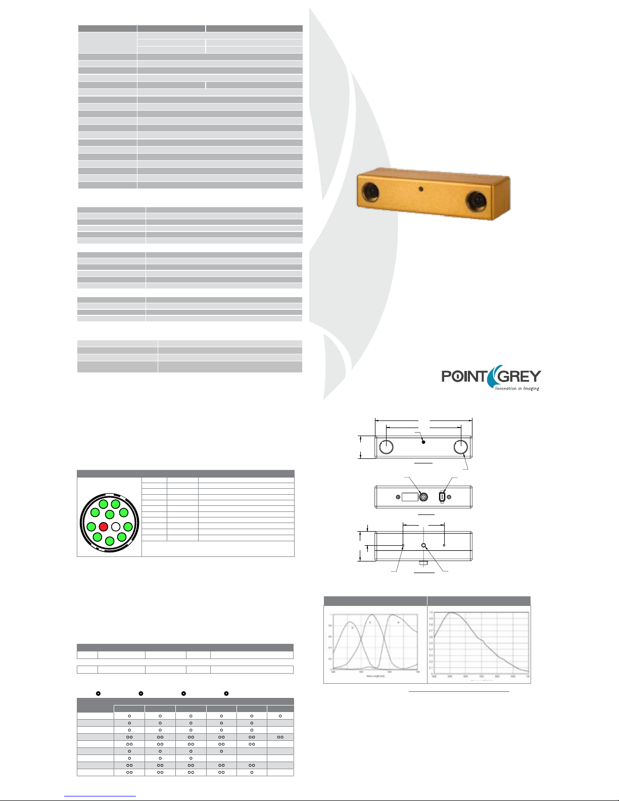
The Bumblebee2 has a 12-pin Hirose HR10 (Mfg P/N: HR10A-10R-12SB) female circular connector on the back
of the case. Camera KIT contents include a pre-wired male connector; refer to the diagram below for wire colorcoding. Additional male counterparts (Mfg P/N: HR10A-10P-12P) can be purchased from Digi-Key (P/N: HR112-ND).
CAMERA INTERFACE
STEREO IMAGE FORMATS
TECHNICAL DRAWINGS
Steady on Receiving power and successful camera initialization
Steady on and very bright Acquiring / transmitting images
Flashing bright, then brighter Camera registers being accessed (no image acquisition)
Steady or slow ashing on and off
Camera rmware updated (requires power cycle),
or possible camera problem
STATUS LED
12 PIN GPIO CONNECTOR
REAR VIEW
IEEE 1394A CONNECTOR
2-M3x4 DEEP BOTTOM VIEW
1/4-20x6 DEEP
TRIPOD MOUNTING HOLE
66.0
47.4
22.3
WITH PROTECTIVE GLASS
3.8mm OR 6mm MICROLENS
STATUS LED
FRONT VIEW
157.0
120.0
36.0
SPECTRAL RESPONSE (QE)
Color Monochrome
For full sensor datasheets, visit www.ptgrey.com/support/kb/index.asp?a=4&q=23
Diagram Pin Function Description
1 IO0 Input / Output (default Trigger_Src)
2 IO1 Input / Output
3 IO2 Input / Output / RS232 Transmit (TX)
4 IO3 Input / Output / RS232 Receive (RX)
5 RT S RS-232 Request to Send
6 CTS RS-232 Clear to Send
7 TX RS-232 Transmit (Output)
8 RX RS-232 Receive (Input)
9, 10 GND
11 V
EXT Voltage limit: 8-30V; Current limit: 1A
12 +3.3V Power external circuitry up to a total of 150mA
To congure the GPIO pins, consult the “General Purpose Input / Output” section of the
PGR IEEE-1394 Digital Camera Register Reference.
The Bumblebee2 GPIO pins are TTL 3.3V pins. Inputs can be congured to accept external trigger signals. When
congured as inputs, the pins are internally pulled high using weak pull-up resistors to allow easy triggering of the
camera by simply shorting the pin to ground (GND). The inputs are protected from both over and under voltage.
It is recommended, however, that they only be connected to 5V or 3.3V digital logic signals. Outputs can be
congured to send an output signal or strobe pulse. When congured as outputs, each line can sink 10mA of current.
1
2
3
4
5
6
7
8
9
10
11
12
The Bumblebee2 can be congured to output images from both sensors at the same time as pixel (byte) interleaved
stereo pairs using Format_7. Pixel interleaved images use a raw 16bit/pixel format, where the rst byte is from the
left camera and the second from the right.
BB2-HIxxx
Mode Pixel Format Max Size FPS Description
3 Raw16 (16bpp) 1024x768 20 Pixel interleaved stereo image
BB2-xxx
3 Raw16 (16bpp) 640x480 48 Pixel interleaved stereo image
1
Use the PAN control to select the camera that is outputting images
Mode
Description
Frames Per Second
1.875 3.75 7.5 15 30 60
640x480 YUV411
• • • • • •
640x480 YUV422
• • • • •
640x480 RGB
• • • • •
640x480 Y8
•• •• •• •• •• ••
640x480 Y16
•• •• •• •• ••
1024x768 YUV422
• • • •
1024x768 RGB
• • •
1024x768 Y8
•• •• •• •• ••
1024x768 Y16
•• •• •• •• •
•
BB2-COL
•
BB2-BW
•
BB2-HICOL
•
BBS-HIBW
STANDARD IMAGE FORMATS
SPECIFICATION BB2-03S2 BB2-08S2
Imaging Sensor
Sony
®
1/3” progressive scan CCD
ICX424 (648x488 max pixels) ICX204 (1032x776 max pixels)
7.4μm square pixels 4.65μm square pixels
Baseline 12cm
Lens Focal Length 2.5mm with 97° HFOV or 3.8mm with 66° HFOV or 6mm with 43° HFOV
A/D Converter 12-bit analog-to-digital converter
Video Data Output 8, 16 and 24-bit digital data (see Supported Data Formats below)
Frame Rates 48, 30, 15, 7.5, 3.75, 1.875 FPS 18, 15, 7.5, 3.75, 1.875 FPS
Interfaces 6-pin IEEE-1394a for camera control and video data transmission
Voltage Requirements 8-30V via IEEE-1394 interface or GPIO connector
Power Consumption 2.5W at 12V
Gain Automatic/Manual
Shutter Automatic/Manual, 0.01ms to 66.63ms at 15 FPS
Gamma 0.50 to 4.00
Trigger Modes DCAM v1.31 Trigger Modes 0, 1, 3, and 14
Signal To Noise Ratio Greater than 60dB at 0dB gain
Dimensions 157mm x 36mm x 47.4mm
Mass 342 grams
Camera Specication IIDC 1394-based Digital Camera Specication v1.31
Emissions Compliance Complies with CE rules and Part 15 Class A of FCC Rules
Operating Temperature Commercial grade electronics rated from 0° to 45°C
Storage Temperature -30° to 60°C
Automatic Synchronization Multiple Bumblebee2’s on the same 1394 bus automatically sync
Fast Frame Rates Faster standard frame rates
Multiple Trigger Modes Bulb-trigger mode, overlapped trigger/transfer
Color Conversion On-camera conversion to YUV411, YUV422 and RGB formats
Image Processing On-camera control of sharpness, hue, saturation, gamma, LUT
Embedded Image Info Pixels contain frame-specic info (e.g. shutter, 1394 cycle time)
Frame Rate Control Fine-tune frame rates for video conversion (e.g. PAL @ 24 FPS)
Strobe Output Increased drive strength, congurable strobe pattern output
RS-232 Serial Port Provides serial communication via GPIO TTL digital logic levels
Memory Channels Non-volatile storage of camera default power-up settings
Temperature Sensor Reports the temperature near the imaging sensor
Camera Upgrades Firmware upgradeable in eld via IEEE-1394 interface.
Lens System High quality microlenses protected by removeable glass system
Accurate Pre-Calibration For lens distortions and camera misalignments
Stereo Pair Alignment Left and right images aligned to within 0.1
1
pixel RMS error
Calibration Retention Minimizes loss of calibration due to shock and vibration
1
Based on a s tereo resolu tion of 640x4 80 and is vali d for all camer a models. Cali bration accu racy will var y from camer a to camera.
IMAGE ACQUISITION
CAMERA AND DEVICE CONTROL
CALIBRATION AND MECHANICS
Page 2
5. Connect the 1394 PCI Card and Cable to the Camera
• Plug the 4.5 meter, 6-pin to 6-pin, IEEE-1394 cable into the 1394 PCI card and
the camera’s1394 Connector.
NOTE: The camera relies on the 6-pin 1394 cable to provide power. If using an
interface card other than that provided, ensure that adequate power is provided.
• If the Microsoft Windows “Found New Hardware Wizard” appears, proceed to
Step 7. Otherwise, proceed to Step 8.
The FlyCapture® User Guide and other technical references can be
found in the Programs > Point Grey Research > PGR FlyCapture
> Documentation directory. Our on-line Knowledge Base
(www.ptgrey.com/support/kb/) also addresses the following problems:
• Article 21: Troublesome hardware congurations
• Article 91: PGR camera not recognized by system and not listed in Device Manager
• Article 93: My laptop’s IEEE-1394 port or PCMCIA card doesn’t supply power to my camera
• Article 145: Image discontinuities or horizontal tearing of images when displayed on monitor
• Article 171: Performance of 1394 devices may decrease after installing Windows XP SP2
• Article 188: Image data acquired by my camera is corrupt and displayed images are broken
• Article 189: Image capture freezes after a period of successful image capture.
Installation
1 2
3
4
Installation
Installation
Troubleshooting
3. Install the IEEE-1394 PCI card
• Turn the computer back on and log into Windows.
• In most cases, the Windows IEEE-1394 drivers will be automatically
installed for the card, with no user input required. However, in some cases
the Found New Hardware Wizard will appear. Follow the prompts
given by the Wizard to install the card.
• Open Windows Device Manager by going to the
Control Panel > System > Hardware tab > Device Manager. Ensure
the PCI card is properly installed as an IEEE 1394 Bus host controller.
4. Install the FlyCapture
®
and Triclops™ Software
• Follow the installation instructions to install the software.
• A dialog will appear asking if you want to downgrade your Windows XP
drivers. If you have installed Service Pack 2, we encourage users to do this.
See this Knowledge Base article for further information:
www.ptgrey.com/support/kb/index.asp?a=4&q=171
7. Conrm Successful Installation
• Check the Device Manager to conrm that installation was successful. Go to the
Start menu, select Run and enter “devmgmt.msc”. Verify the camera is listed
under “Point Grey Research Devices”.
1. Recommended System Conguration
• Windows XP Service Pack 1
• 512MB of RAM
• Intel Pentium 4 2.0GHz or compatible processor
• AGP video card with 64MB video memory
• 32-bit standard PCI slot for the IEEE-1394 PCI card
• Microsoft Visual C++ 6.0 (to compile and run example code)
2. Electrostatic Precautions and Camera Care
• Users who have purchased a bare board camera should:
• To clean the imaging surface of your CCD, follow the steps outlined in
www.ptgrey.com/support/kb/index.asp?a=4&q=66.
• Extended exposure to bright sunlight, rain, dusty environments, etc.
may cause problems with the electronics and the optics of the system.
• Avoid excessive shaking, dropping or mishandling of the device.
CPU
RAM VIDEO
PORTS
OS
2.0GHz
or equivalen t
Windows XP
SP1
512mb AGP
64mb
IEEE-1394a
• Either handle bare handed or use non-chargeable
gloves, clothes or material. Also use conductive shoes.
• Install a conductive mat on the oor or working table
to prevent the generation of static electricity.
• When handling the camera unit, avoid touching the
lenses. To clean the lenses, use a standard camera lens
cleaning kit or a clean dry cotton cloth. Do not apply
excessive force.
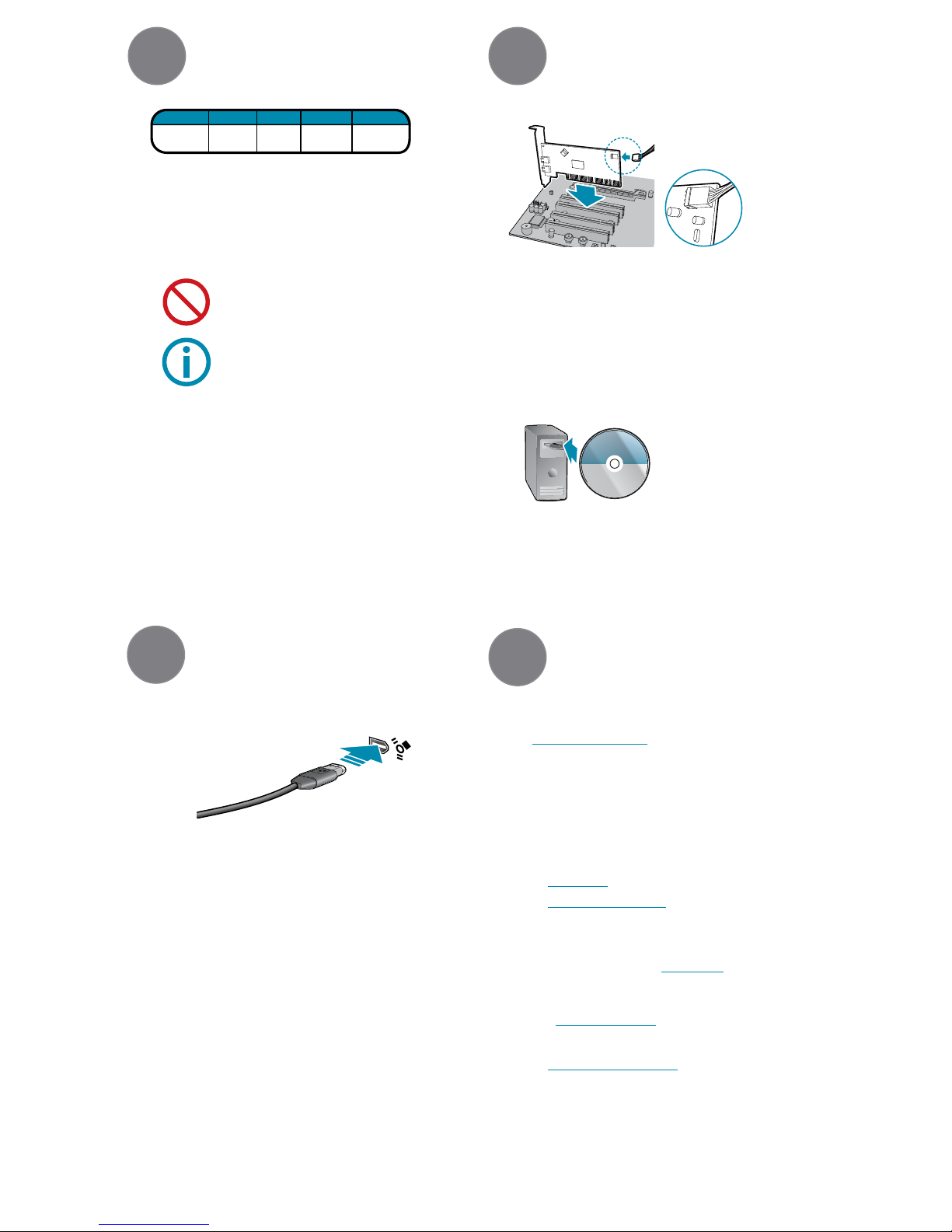
• Turn computer off and place the IEEE-
1394 PCI card in an open PCI slot.
• Connect the 4-pin connector on the
card to the PC power supply.
FLYCAPTURE
Software and Drivers
• Insert the software CD-ROM. If
the Installation Wizard does not
automatically run, browse to your
CD-ROM directory and run the
setup.exe le.
FIREWIRE
1394a
6. Install the Camera Driver
• Click “Install from a list or specic location” and click “Next”.
• Select “Don’t search. I will choose the driver to install” and “Next”.
• Click “Have Disk” and browse to C:\Program Files\Point Grey Research\PGR
FlyCapture\driver\signed\<your platform>, click “Open”, then “OK”.
• Select the camera model. Click “Next”.
• You will be prompted to continue installation - click “Continue Anyway” then
“Finish” to complete installation.
Email:
For all general questions about Point Grey Research please contact
us at info@ptgrey.com.
For technical support (existing customers only) contact
us at www.ptgrey.com/suppor t/contact/.
Main Ofce:
Mailing Address: Tel: +1 (604) 242-9937
Point Grey Research, Inc. Toll Free (N. America only): +1 (866) 765-0827
Richmond B.C. Canada Fax: +1 (604) 242-9938
12051 Riverside Way Email: sales@ptgrey.com
V6W 1K7
Knowledge Base:
Find answers to commonly asked questions in our knowledge
base at www.ptgrey.com/suppor t/kb/.
Downloads:
Users can download the latest manuals and software
from www.ptgrey.com/support/downloads/.
CONTACTING POINT GREY RESEARCH
 Loading...