

Page 1
Getting Started with the
Blackfly USB 3.0 Digital Camera
Will your system support the
Do you have a downloads account? Do you have all the parts you need?
camera?
Recom mended System Configuration:
n OS—Windows, Linux (32- and 64-bit)
n CPU—Intel Co re 2 Duo, or equivalent
n RAM—2GB RAM
n Video—128 MB
n Ports—PCIe 2.0 compatible ho st controller with
USB 3.0 connecto r
n Software—Microsoft Visual Stud io 2010 (to
com pileand run example code)
See Technical Application Not e 10359for information
on recommended system components for USB3.0.
The Point Grey downloads page has m any resources t o help
you op erate you r camera effectively, including:
n Software, including Drivers (required for installation)
n Firmware updates and release notes
n Dimensional drawings and CADmodels
n Doc ument ation
To access the downloads resources you must have a
downloads accoun t.
1. Go to t he Po int Grey downloads page.
2. Under Register (New Users), complete th e form, then
click Submit.
After you sub mit your registration, you will receive an email
with instru ctions on how to activate your accoun t.
For More Information
For m ore informat ion about... See...
Your camera's set tings and capabilit ies Technical Reference Manual
Using the Fly Cap demo program the Online Help included with t he tool
Accessing customer downloads Knowledge Base A rticle 10142
Selecting a lens Knowledge Base A rticle 10269
Recommended and unsupported system components for US B 3.0 Technical Application Note 10359
Using USB 3.0 and Linux Technical Application Note 10685
Sett ing up multiple USB 3.0 cameras Technical Application Note 10350
The FlyCapture SDK help and other technical references can be found in the
Programs>Point Grey Research>PGRFlyCapture>Documentati on directory. Our
online Knowledge Base addressesmany questions.
To install your camera you willneed th e following
com ponents:
n USB 3.0 cable
n 6-pin GPIOcable
n Lens
n Tripod adapter (optional)
n Interface card
Point Grey sells a number o f the additional parts
required for installation. To purc hase, visit the Point
Grey website Acc essoriespage.
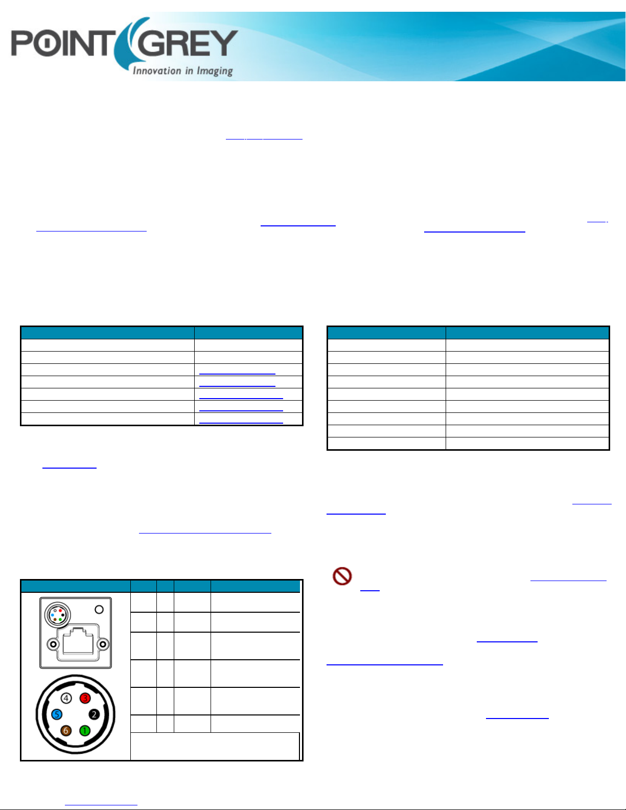
Status Indicator LED
LED Stat us Description
Off Not receiv ing power
Steady gr een Receiving power
Flashing yellow /Steady yellow Initiali zing FPGA
Steady y ellow-green Sensor powered down
Steady brig ht green Acquiring and transmitti ng images
Flashing bright, then brig hter gr een A ccessing camera r egisters (no image acquisition)
Flashing green and red Updating firmwar e
Flashing red Temporary problem
Steady red Serious problem
Camera Interface
USB 3.0 Connector
The camera is equipped with a USB 3.0 Micro-B connector th at is used for power,
data transmission, and camera con trol. For more detailed information, consult the
USB 3.0 specification available from http://www.usb.org/developers/docs/.
General Purpose I/O Connector
The camera is equipped with a 6-pin GPIO con nector on the back of t he case; refer
to th e diagram for wire co lor-coding.
Diagram Color Pin Function Description
Green 1 Power +12 V DC Camera Power
Black 2 Opto Input 1 Opto-isolated input
Red 3 NC / +3.3 V
White 4
Blue 5 Opto GND
Brown 6 GND DCcamera power ground
To configure the GPIOpins, consult t he General Purpose
Input/Output section of your camera's Technical Reference
Manual.
Opto Output
+3.3 V output. Current 120 mA
(nominal).
Firmwar e enabled
Opto-isolated output
1
Ground for opto-isolated I/O,
not connected t o camera
ground
Camera Care
To c lean t he imaging surface of your camera, follow the steps o utlined in Knowledge
Base Article 10243.
Extended exposure to bright sunlight, rain, dusty environments, etc. may cause
problems with th e electronics and optics of the system.
Avoid excessive shaking, dropping, or mishandling o f the device.
Do not openthe camera housing. D oingso voidsthe Hardware Warranty.
Avoidelectrostatic charging. For more details, consult Knowledge Base Article
10147.
Contacting Point Grey Research
For all general questions pleasec ontact us at info@ptgrey.com.
For technical support (existing customers only) c ontact u s at
www.ptgrey.com/support/ticket/.
Main Office:
Mailing Address:
Point Grey Research, Inc.
12051Riverside Way
Richmond, BC, Canada V6W 1K7
Tel:
+1 (604)242-9937
Toll Free
(North America only )
Fax:
+1 (866)765-0827
+1 (604)242-9938
Email: sales@ptgrey.co m
Page 2
Installing Your Interface Card and Software
1. Install your Interface Card
Ensure the card is installed per the
manufacturer'sinstructions.
Connect the internal ID E or SATApower
con necto r on the card to th e com puter
power supp ly.
Alternatively, use your P C's built-in host
con troller, if equipped.
Open the Windows Device Manager. Ensure the card is properly installed under
Universal Serial Bus Controllers. An exclamation point (!) next to the c ard
indicates t he driver h as not yet been installed.
2. Install the FlyCapture® Software
For existing users w hoalready have FlyCapture installed, we recommend
ensuringyou have the latest versionfor optimal performance of your
camera. If youdo not needto installFlyCapture, use the DriverControlGUI
to install and enabledrivers for your card.
a. Login to the Point Grey downloads p age.
b. Select your Camera and Operating System from the drop-down lists and
click t he Search button .
c. Click on the Software search results to expand the list.
d. Click the appropriate link to begin the dow nload and installation.
After the d ownload is c omplete, the FlyCapture setup wizard begins. If the
wizard d oes not start aut omatically, double-click the .exe file t o open it. Follow
the steps in each setup dialog.
3. Enable the Drivers for the card
During theFlyCapture installation, you areprom pted to select your interface
driver.
In the Interface Driver Selection dialog, select theI wil l use USB cameras.
For optimal p erformance, after setup, we recomm end configuring th e
pgrxhci (UsbPro) driver on th e host controller to op erate direct ly with the
camera.
To uninstall or recon figure the driver at any time after setup is co mplete, use th e
DriverControlGUI.
Installing Your Camera
1. Install the Tripod Mounting Bracket (optional)
The ASA and ISO-compliant tripod m ounting bracket attaches t o the camera
using the included
2. Attach a L ens
Unscrew the d ust cap from the CS-mount lens holder to install a lens. Note: the
camera can be used with a removable 5 mm C-mount adapter.
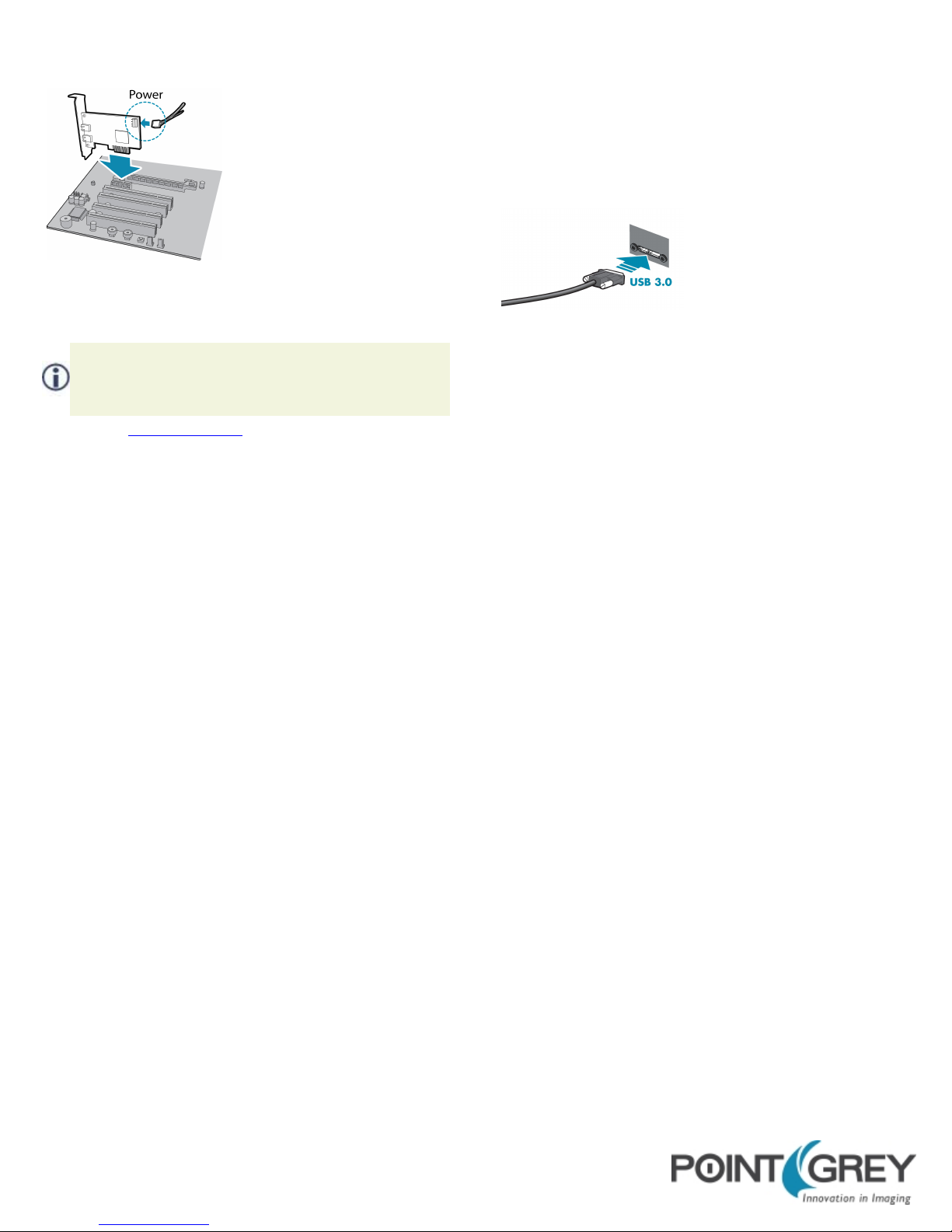
3. Connect the i nterface Card and Cable to the Camera
4. Plug in the GPIO connector
5. Confirm Successful Installation
Check Device Manager to confirm that installation was successful.
a. Go to the Start menu, select Run, and ent er devmgmt.msc.
Verify the camera is listed under "Point Grey Research Devices."
b. Run the FlyCap pro gram: Start-> FlyCapture SDK-> FlyCap
The FlyCap program can beused to test the camera's image acquisition
capabilities.
Changes to your c amera's installation configuration can be made using utilities
available in the FlyCapture SDK.
metal
screws.
Plug the interface c able into the host
con troller card and th e camera. The
cable jack screws can be used for a secure
con nection.
11/6/2014 Point Grey Research, Inc. Logo, Fl yCapture, and Blackfly USB 3.0 are trademark s or reg istered tr ademarks of Point Grey Research, Inc in Canada and other countries.
 Loading...