

Page 1

AIRCRAFT EMERGENCY LOCATOR
TRANSMITTER
OPERA
FOR HORIZONTAL MOUNTING IN FIXED WING AIRCRAFT OR
ANGULA
R MOUNTING IN ROTARY WING AIRCRAFT.
TION AND INSTALLATION
INS
TRUCTIONS FOR:
MODE
L 4000-10 (AP)(AF)
TSO-C91A
WARNING!
FOR AVIATION EMERGENCY USE ONLY.
AUTHORIZED OPERATION IS PROHIBITED.
UN
POINTER AVIONICS
207 Centennial Court,
Kitchener, ON, N2B 3X2, Canada
PH. 519 – 648 – 3778 Fx. 519 – 648 – 3075
Email : SALES@POINTERAVIONICS.COM
Page 2

INDEX
PAGE
SECTION 1 Description of Pointer Sentry ELT 2
SECTION 2 Pre-Installation Checkout 3
SECTION 3 Installation Instructions 4 thru 9
SECTION 4 Functional Testing 10 and 11
SECTION 5 Operating Instructions 12 and 13
SECTION 6 Battery Information 14
SECTION 7 Performance Requirements & Spec.’s 15
SECTION 1
DESCRIPTION
1-1 POINTER SENTRY ELT is a self-contained emergency locator transmitter capable of manual or automatic
1-2 POINTER SENTRY ELT is designed to withstand forced landing and crash environmental conditions and survive
1-3 Automatic activation is accomplished by a deceleration sensing inertia switch. The inertia switch is designed to
operation.
in an operable condition. The highest quality materials and components have been selected for manufacturing to
insure rugged, reliable emergency equipment.
activate when the unit senses longitudinal inertia forces as required in TSO-C91A.
NOTE: When properly installed, parallel to the line of flight, POINTER SENTRY ELT will not activate due to
turbulence, normal operations, or aerobatics.
1-4 POINTER SENTRY ELT (see Figures 1 and 2) consists of:
A A high-impact, fire retardant, waterproof case with carrying handle.
B A solid-state transmitter operating at the assigned emergency frequencies of 121.5 MHz and 243.0 MHz. Normal
C A battery pack P/N C2020 consisting of alkaline "C" cells in an impact resistant molded housing, with
D An antenna connector outlet for fixed or telescopic antenna.
E A remote "ON-AUTO-RESET" control jack.
FAmaster"ON-OFF-AUTO"switch.
G An Inertia switch with electrical reset feature
H An external whip antenna, P/N3001 with coax cable, P/N 3002.
I Remote cabin switch kit P/N2019-10, and 2021-10 master switch guard and hardware.
J An Instrument Panel Warning Label to be affixed adjacent to Remote Switch. (Transport Canada requirement)
K A preformed anodized quick-detach mounting bracket, P/N 2017-10.
L An operation and installation manual.
M A warranty registration card.
N A Transport Canada required "ELT LOCATED HERE ” Decal.
O Special high performance antenna P/N 3003 (OPTIONAL)
P A storable telescopic antenna, P/N 2006-10 with tether line.
transmission is modulated by a distinctive down swept tone.
interconnecting plug assembly. The battery pack is available from your local POINTER dealerordirectfromthe
distributor.
REV 1 - JULY/97
2
Page 3
PRE-INSTALLATION
SECTION 2
2-1 POINTER SENTRY ELT is designed to be installed in the aft section or cabin of the aircraft. The installation and
a. Remove POINTER SENTRY ELT from carton and remove foam guard from master switch. Verify the master
b. Install 50 ohm load on antenna RF output.
c. Place master switch in the "AUTO" position.
testing should be made by qualified personnel in accordance with TRANSPORT CANADA regulations, referring to
the Engineering and Inspection Manual, Part 1, Chapter II, Section 2.2. Appropriate weight and balance
computations shall be completed and entered in the Aircraft Logbook for each installation.
switch is in the "OFF/RESET" position (See Figure 1)
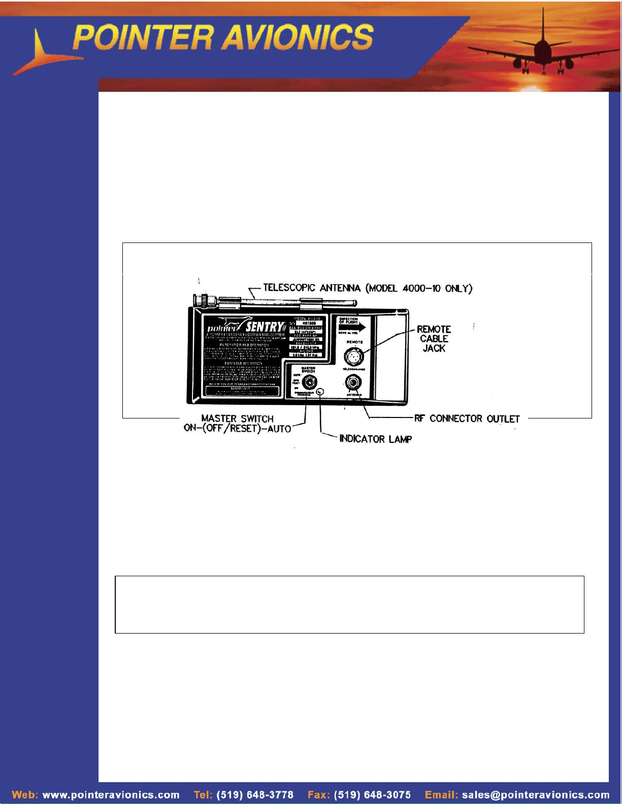
FIGURE 1. POINTER SENTRY 4000-10 OPERATING DETAILS
d. Shake the unit firmly parallel to the "DIRECTION OF FLIGHT" arrow on the unit face. A down sweeping tone will
e. Place the master switch in the "ON" position. Unit should again operate.
f. Place the master switch in the "OFF" position. POINTER SENTRY ELT IS NOW READY FOR INSTALLATION.
be heard on the monitoring radio at 121.5 MHz. or 243.0 MHz. To reset "G" switch turn master switch to "OFF"
momentarily.
NOTICE
IF FOR ANY REASON POINTER SENTRY ELT DOES NOT TRANSMIT DURING ANY OF THE ABOVE TESTS,
REPEAT THE PROCEDURES. IF THE UNIT STILL FAILS TO OPERATE, RE-PACKAGE THE ENTIRE UNIT AS
SHIPPED, COMPLETE THE REGISTRATION CARD, PLACE A NOTE OF EXPLANATION AND THE REGISTRATION
CARDINSIDETHEBOXANDRETURNUNITTODEALERORDISTRIBUTORFORREPLACEMENT.
3
Page 4

SECTION 3
INSTALLATION INSTRUCTIONS
3.0 GENERAL
The following instructions are a general guide for the installation of the POINTER SENTRY Aircraft Emergency
Locator Transmitter. Installation shall be made in accordance with the requirements of FAA document AC
43-13-2, ACCEPTABLE METHODS, TECHNIQUES, & PRACTICES - AIRCRAFT ALTERATIONS. Each
installation must satisfy air worthiness requirements pertinent to type and country of registry.
For installation in Canadian registered aircraft, refer to TRANSPORT CANADA Engineering and
Inspection Manual, Part II, Chapter III, Section 3.12.7(e)
CAUTION!
INSTALLATION IN THE PRESSURIZED AREA OF AN AIRCRAFT CONSTITUTES A MAJOR
MODIFICATION. CONSULT REGIONAL TRANSPORT CANADA ENGINEERING OFFICE BEFORE
PROCEEDING.
3.1 MOUNTING LOCATION - FIXED-WING AIRCRAFT
a. The POINTER SENTRY ELT should be mounted as far aft as possible. Location should be chosen to afford easy
b. Select an area in the cabin such as between the seats, in the luggage area, cabin floor, radio rack or any flat
c. It is important that the unit be mounted PARALLEL TO or SLIGHTLY ABOVE the line of flight in fixed-wing aircraft.
and repeated access to the ELT for testing, servicing, and manual activation/deactivation when the aircraft is on
the ground.
surface parallel to the longitudinal axis of the aircraft. Assure that the mounting area is solid.
The POINTER SENTRY ELT m ust be solidly mounted. DO NOT install in an area subject to flexing or drumming
vibrations. See Section 3.3 and 3.4 for installation details.
4
Page 5

3.2 MOUNTING LOCATION - ROTARY-WING AIRCRAFT (HELICOPTER)
a. The POINTER SENTRY ELT must be located on the primary structure. This location must be accessible for
manual activation/deactivation, testing, and servicing when the helicopter is on the ground. See Section 3.4 for
installation details.
All hardw are shown is included in the standard Pointer Sentry 4000-10 Installation Kit.
5
Page 6

NOTES: 1. Transmitter may be
"Remote" Cable Connector to mount, but must
Master switch
Clip
Whip Antenna Connector equivalent material.
rotated longitudinally
FACE FORWARD as
shown by the arrow.
2. Mounting surface must
be flat and rigid over the
entire area and of
2024.23 AL ALY or
#6 Pan Head machine screw, washer, and nut. (4 ea.
ELT MOUNTING
BRACKET Position hold down strap between center and
It is important that the unit be mounted PARALLEL TO the longitudinal axis of the aircraft. DO NOT MOUNT THE UNIT
AT A DOWNWARD OR NEGATIVE ANGLE. (Fixed-wing aircraft only)
Figure 3. MOUNTING POINTER SENTRY IN FIXED WING AIRCRAFT
required.) Allmountinghardwaretobeofsuitable
aircraft quality.
rear mounting screws.
6
Page 7

3.3 ELT INSTALLATION DETAILS - FIXED-WING AIRCRAFT
NOTE:
Prior to installing the ELT transmitter, check that battery replacement date is
marked in the space on the label at the end of the unit.
3.3-1 Attach mounting bracket to the aircraft structure so that, when the unit is installed, the "DIRECTION OF FLIGHT"
arrow on the ELT control face points forward in the direction of flight. Drill four holes and attach the mounting
bracket with # 6 pan head screws. All attaching hardware must be of material and type suitable for Aircraft
application. Heads must be flush with bracket surface.
3.3-2 Figure 3 shows a typical fixed-wing aircraft installation. Insert transmitter into the mounting bracket and position
bracket strap forward of rear telescopic antenna clip and over the unit case. Open latch, attach to clip and lock into
place.
3.3-3 Place the Master Switch in the "AUTO" position and install Master Switch Guard clip.
3.3-4 Record the installation in Aircraft Logbooks.
3.3-5 A remote whip antenna and coaxial cable are provided with model 4000-10 for external mounting. See
Section 3.5 for antenna mounting details.
3.3-6 EXTERNAL MARKING. An "ELT LOCATED HERE" decal is supplied with each system, to indicate
transmitter location.
3.4 INSTALLATION DETAILS - ROTARY-WING (HELICOPTER)
3.4-1 All mounting instructions are identical to Fixed-Wing with the exception of the mounting angle as shown in Fig. 4.
Mounting Instructions
are identical to fixed
wing A/C (ref Fig.3)
HORIZONTAL
FIGURE 4. MOUNTING POINTER ELT IN ROTARY-WING AIRCRAFT
Page 8

3.5 WHIP ANTENNA LOCATION AND MOUNTING
3.5-1 The POINTER SENTRY 4000-10 W hip Antenna and coaxial cable are provided to permit external antenna
(a) Mount Whip Vertically on the upper surface of aircraft (or helicopter).
(b) Locate so as to minimize RF coupling from adjacent communications antennae. Maintain maximum practical
(c) Must not foul other antennae when whipped in flight.
(d) Mount Whip antenna as close as possible to transmitter. Neatly coil and tie any excess in the 5 foot coax cable.
3.5-2 WHIP ANTENNA INSTALLATION
3.5-3 ANTENNA MODIFICATION For high perform ance aircraft.
radiation. Use ONLY the cable furnished with the unit. Whip antenna should be mounted as far aft as possible on
the surface of the aircraft (or helicopter) as this area is normally less susceptible to impact damage.
Pay particular attention to the following:
distance from all other antennae.
NOTE: COAXIAL CABLE MUST NOT BE CUT OR ALTERED.
Figures 5 and 6 illustrate details of Metal and Fabric-skin aircraft antenna installations.
The POINTER SENTRY ELT W hip antenna may be modified to reduce wind-loading at higher speeds as shown
below in Figure 7. (See Section 7 for max. speed.)
8
Page 9

3.6 REMOTE SWITCH OPTION
The Remote Switch/Monitor feature is required for all installations where the transmitter is not accessible to the
pilot in flight. This Remote Switch/Monitor enables the pilot to control the ELT in flight, and also visibly detects if
ELT is transmitting. This is also useful for testing without gaining access to the transmitter.
3.6-1 Items included in the remote switch kit are listed below:
3.6-2 The remote switch/Monitor wiring diagram is shown in figure 9.
3.6-3 SelectalocationontheinstrumentpanelfortheRemoteSwitch/Faceplateassembly. A3/4"squareholeis
required for switch installation.
3.6-4 Figure 10 shows pin/terminal details for the connector and remote switch. Connect the wires as shown in Figure 9
using ONLY the connector and switch supplied in the kit. (Using any other type of switch voids the TRANSPORT
CANADA approval of the system).
DESCRIPTION QTY.
Rocker switch, DPDT 1
WarningLabel 1 (See3.6.11below)
Remote connector (Locking) 1
Face Plate, (ON/AUTO/RESET) 1
3.6-5 At panel end of cable, remove outer cable covering, form shielding into pigtail. Connect pigtail to aircraft ground.
3.6-6 At transmitter end of cable, remove cable covering and form shielding into pigtail. Connect with pin D of the
3.6-7 An in-line fuse or circuit breaker (1 amp max) must be installed in the aircraft power circuit to the Remote Switch.
3.6-8 12/24V aircraft. The remote switch "#2" terminal must be connected to the Remote Connector "H" pin in 12/14
3.6-9 Mating the remote connector to the transmitter. Before mating the connector to the transmitter, apply silicon
3.6-11 Affix the warning label which reads (For Aviation Emergency Use Only ..............) to the instrument panel above,
remote connector.
Volt systems, and to the "E" pin in 24/28 Volt systems.
grease to the contacts to create a waterproof seal.
below, or adjacent to the Remote Switch/Face Plate to comply with Transport Canada Requirements. This
completes Remote Switch Installation.
9
Page 10

4.0 GENERAL
The POINTER SENTRY ELT System must undergo a functional test for the following reasons:
(a) After initial installation
(b) After system maintenance, such as battery pack replacement.
SECTION 4
FUNCTIONAL TESTING
(c) Thereafter at owner's or operator's discretion. Annual or more frequent inspection intervals are
An annual PERFORMANCE TEST and recertification, by an approved Avionics facility, is mandatory for
installations aboard Canadian Registered aircraft.
4.1 TEST PREPARATION
4.1-1 Visually inspect unit, connections and mounting bracket occasionally for cleanliness and secureness. Check fixed
antenna mounting for tightness. Verify master switch in "AUTO" position.
4.1-2 Test unit occasionally using procedure outlined in FAA advisory circular AC-20-81. DON'T overtest. If more than
one cumulative hour of testing occurs before the replacement date of the battery pack, the pack should be
replaced.
4.1-3 Functional test of equipment in Canadian registered aircraft shall be performed and no more than three Audio
Modulation sweeps should be permitted. Refer to Section 3.12.7(d) of Part II, Chapter III of TRANSPORT
CANADA Engineering and Inspection Manual.
recommended.
NOTE: Where aircraft comm. receiver is used:
(a) Tune to 121.5 MHz
(b) Adjust manual squelch to maximum
(c) Turn up receiver volume until slight background noise is heard.
(An Automatic Squelch receiver will not reveal a defective ELT with a low RF output power.)
4.2 POINTER SENTRY ELT FUNCTIONAL DETAILS
4.2-1 AUTOMATIC PORTABLE (AP). (Unit installed without the remote switch).
4.2-2 “G” Switch: Used to activate the POINTER SENTRY in an emergency situation. The “G” switch can be operated
TheunitMasterSwitchfunctionsasfollows:
AUTO: Used to arm the POINTER SENTRY ELT for automatic activation by the “G” switch only.
ON: Used to activate the transmitter for test or emergency situations. The ON switch bypasses the
automatic activation switch.
OFF/RESET: Used to de-activate the transmitter during handling and to reset the automatic activation
switch.
by impact only.
10
Page 11

4.2-3 AUTOMATIC FIXED (AF) (unit installed W ITH the remote switch)
The Remote Switch functions as follows: (With Master Switch in "AUTO" position)
ON: Used to remotely activate the transmitter for a test or emergency situation. An
AUTO: Used to arm the POINTER SENTRY ELT for automatic activation by the "G" switch
RESET: Used to deactivate and rearm the transmitter after automatic activation by the "G"
.
4.3 FUNCTIONAL TEST OF AIRCRAFT-INSTALLED POINTER SENTRY ELT
example of such an emergency situation would be a forced landing with an impact
insufficient to activate the "G" switch.
only.
switch.
4.4 MAINTENANCE
4.4-1 If the ELT fails to operate properly during the functional test, remove only the main unit and return to POINTER
4.4 PERFORMANCE TEST (Canadian Registered Aircraft Requirement)
4.4.1 The Engineering and Inspection Manual, Part 1, Chapter III, Section 3.12.7(e) describes a performance test to be
AVIONICS for inspection and repair.
accomplished every 12 months. This test MUST be carried out by an approved Avionics Facility and so certified
on a MAINTENANCE RELEASE TAG.
11
Page 12

SECTION 5
OPERATING INSTRUCTIONS
5.0 GENERAL. Your POINTER SENTRY ELT has been engineered to provide the most reliable operation possible.
5.1 It is recommended that the following steps be taken to insure the best possible operation in an emergency:
5.1-1 OPERATING MODES OF POINTER SENTRY ELT INSTALLED IN AIRCRAFT.
Every contingency has been considered in the design and construction of the ELT system. The following section
will acquaint you with the simple operational procedures of the POINTER SENTRY ELT. It is recommended that
you familiarize yourself thoroughly with these procedures and have them firmly in mind to add to your flying
confidence.
(a) Become thoroughly familiar with the POINTER SENTRY ELT instructions.
(b) Keepthemonhandintheaircraftatalltimes.
(c) Visually inspect the unit at regular intervals for cleanliness and secureness. Check External antenna
mounting and cable connections for tightness.
The following table gives the switch positions and functions for various situations.
5.1-2 After a forced landing, if aircraft receiver is operable, listen on 121.5 MHz for POINTER ELT transmissions.
Ensure that external antenna is clear of obstructions.
5.1-3 The range of POINTER ELT varies according to weather and topography. In general, the swept tone signal
can be heard up to 30 miles by a s earch aircraft at 10,000 Ft. Stay close to the downed aircraft to permit
easier spotting by airborne searchers.
CAUTION: DO NOT T URN POINTER ELT OFF - EVEN AT NIGHT as search aircraft may be enroute around the
clock. Even when you have been sighted or think you have, the spotting aircraft may not be able to relay an
accurate or timely "fix" on your position without a continued signal.
12
Page 13

5.2 OPERATING POINTER SENTRY ELT IN THE PORTABLE MODE
5.2-1 After forced landing or aircraft accident it may be desirable to use POINTER SENTRY ELT in the portable mode.
5.2-2 REMOVAL OF TRANSMITTER FROM AIRCRAFT.
5.2-3 Consider such factors as Terrain, Temperature and Precipitation when choosing a location for the transmitter to
BEST TRANSMISSION MAY BE OBTAINED BY:
Various reasons may necessitate this, such as:
(a) Broken or disabled whip antenna.
(b) Severed whip antenna cable.
(c) Danger of fire or explosion in aircraft.
(d) Temperature extremes in aircraft.
(e) Poor transmitting location.
(f) Water ditching with forced evacuation.
NOTE: ACCOMPLISH AS QUICKLY AS POSSIBLE TO RESUME OR START EMERGENCY SIGNAL.
(a) Bend Switch Guard away from unit Master Switch and place in “OFF” position.
(b) Disconnect Remote Antenna Cable.
(c) Disconnect Remote Switch Cable (if applicable).
(d) Remove telescopic antenna from stowage clips. Unlatch hold down strap and remove unit from bracket.
(e) Insert telescopic antenna into the ANT receptacle. Extend antenna fully.
(F) Turn unit master switch to “ON” position. DO NOT USE “AUTO” position!
radiate from.
(a) Keeping antenna vertical
(b) Setting transmitter upright on a metallic surface,suchasanaircraftwingorstabilizer.
(c) If terrain prohibits good transmission (such as a deep valley or canyon), place transmitter on high ground
or hold in hand on high place.
13
Page 14

SECTION 6
BATTERY INFORMATION AND REPLACEMENT
6GENERAL
6.1 Power is derived from a pre-formed foam battery pack consisting of 5 1.5 V Alkaline "C" size batteries in series.
This assembly has been moisture-sealed and fitted with a battery lead connector.
6.2 W HEN TO REPLACE BATTERY PACK:
6.2-1 In accordance with FAA/TRANSPORT CANADA regulations,batteriesmustbereplacedafter2yearsshelfor
service life or for any of the following reasons:
(a) Afterthetransmitterhasbeenusedinanemergencysituation(includinganyinadvertentactivationof
unknown duration).
(b) After the transmitter has been operated for more than one cumulative hour (e.g. time accumulated in
several tests and an inadvertent activation of known duration).
(c) On or before battery replacement date. (Battery replacement date is marked on the battery pack and the
label at end of transm itter.)
Check with your local dealer or distributor for approved replacement battery packs.
WARNING: DO NOT ATTEMPT TO RECHARGE BATTERY PACK!
6.3 REMOVING THE TRANSMITTER FROM THE AIRCRAFT (See Figure 11)
6.3-1 Transmitter must be removed from aircraft for battery replacement by the following steps:
(a) RemoveSwitchGuardandplacetheMasterSwitchinthe"OFF"position.
(b) Disconnect the antenna cable, and, where applicable, the remote connector.
(c) Open latch on hold-down strap, and remove Transmitter from mounting bracket.
6.4 REMOVE THE BATTERY PACK AS FOLLOWS:
(a) Remove six screws from back cover.
(Retain Teflon washers)
(b) Remove cover (save gasket), and
disconnect the battery transmitter
connectors.
(c) Remove and replace battery pack,
reversing the above procedure.
(d) Exercise care not to overtighten the
six base plate screws upon
reassembly
6.5 Apply new battery replacement date label, supplied with replacement pack, on transmitter end prior to
re-installing transmitter in aircraft.
6.6 After re-installing transmitter in aircraft, test in accordance with Section 4.3-Functional testing, p.11.
14
Page 15

15
Page 16

WARRANTY
POINTER, INC. warrants each new Pointer Emergency Locator Transmitter to be free of defects in
material and workmanship, to the original purchaser, indefinitely provided the battery pack is Pointer, Inc.
manufactured and installed current. The Company will repair or replace, free of charge, at its factory, any
t or parts found to be defective under normal use and service - PROVIDED that the enclosed warranty
par
card is properly completed and mailed within 15 days after installation and is on file with POINTER. This
warranty does not cover cost of removal or reinstallation of unit in the aircraft.
This warranty does not cover defects resulting from alterations, improper use, or installation, tampering or
failure of the purchaser to follow normal operating procedures outlined in the user's instructions, nor for
example, does it cover damage resulting from acts of God, such as floods, tornadoes, or lightning.
This warranty is made only to original purchasers and does not cover the responsibility for the shipping
expenses in returning the transmitter or any part thereof to POINTER or returning the transmitter to the
chaser.
pur
THE WARRANTY PROVISIONS SET FORTH ABOVE ARE IN LIEU OF ANY AND ALL OTHER
WARRANTIES, WHETHER EXPRESSED OR IMPLIED, INCLUDING THE WARRANTIES OF
MERCHAN
OR LIABILITY WHATSOEVER ON THE PART OF POINTER OR ANY OF ITS FRANCHISED DEALERS.
TABILITY OR FITNESS FOR A PARTICULAR PURPOSE, AND ANY OTHER OBLIGATIONS
NOTICE
THIS MANUAL OF INSTRUCTIONS ARE A GENERAL GUIDE FOR THE INSTALLATION OF POINTER
SENTR
ACC
INS
Y EMERGENCY LOCATOR TRANSMITTERS. INSTALLATION SHOULD BE MADE IN
ORDANCE WITH FAA PART 43/ TRANSPORT CANADA REGULATIONS AND BY AN APPROVED
TALLATION FACILITY.
POINTER AVIONICS
207 Centennial Court,
Kitchener, ON, N2B 3X2, Canada
PH. 519 – 648 – 3778 Fx. 519 – 648 – 3075
Email : SALES@POINTERAVIONICS.COM
 Loading...