

Page 1
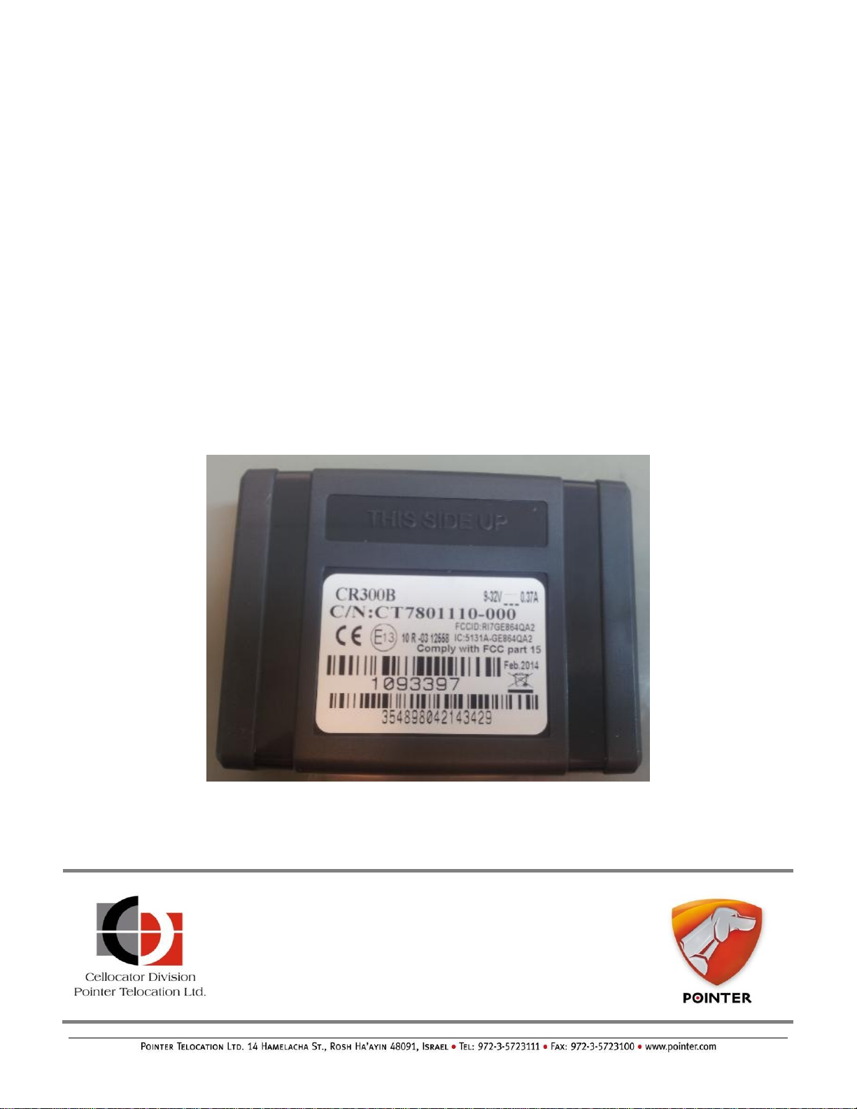
CR Family Hardware
Installation Guide
Proprietary and Confidential
Version 1.3
Revised and Updated: February 13, 2016
Copyright © 2016 by Pointer Telocation, Ltd.
Page 2

CR Family Hardware
Installation Guide
Legal Notices
IMPORTANT
1. All legal terms and safety and operating instructions should be read thoroughly before
the product accompanying this document is installed and operated.
2. This document should be retained for future reference.
3. Attachments, accessories or peripheral devices not supplied or recommended in
writing by Pointer Telocation Ltd. may be hazardous and/or may cause damage to the
product and should not, in any circumstances, be used or combined with the product.
General
The product accompanying this document is not designated for and should not be used in
life support appliances, devices, machines or other systems of any sort where any
malfunction of the product can reasonably be expected to result in injury or death.
Customers of Pointer Telocation Ltd. using, integrating, and/or selling the product for use
in such applications do so at their own risk and agree to fully indemnify Pointer Telocation
Ltd. for any resulting loss or damages.
Warranty Exceptions and Disclaimers
Pointer Telocation Ltd. shall bear no responsibility and shall have no obligation under the
foregoing limited warranty for any damages resulting from normal wear and tear, the cost
of obtaining substitute products, or any defect that is (i) discovered by purchaser during
the warranty period but purchaser does not notify Pointer Telocation Ltd. until after the
end of the warranty period, (ii) caused by any accident, force majeure, misuse, abuse,
handling or testing, improper installation or unauthorized repair or modification of the
product, (iii) caused by use of any software not supplied by Pointer Telocation Ltd., or by
use of the product other than in accordance with its documentation, or (iv) the result of
electrostatic discharge, electrical surge, fire, flood or similar causes. Unless otherwise
provided in a written agreement between the purchaser and Pointer Telocation Ltd., the
purchaser shall be solely responsible for the proper configuration, testing and verification
of the product prior to deployment in the field.
POINTER TELOCATION LTD.’S SOLE RESPONSIBILITY AND PURCHASER’S SOLE REMEDY
UNDER THIS LIMITED WARRANTY SHALL BE TO REPAIR OR REPLACE THE PRODUCT
HARDWARE, SOFTWARE OR SOFTWARE MEDIA (OR IF REPAIR OR REPLACEMENT IS NOT
POSSIBLE, OBTAIN A REFUND OF THE PURCHASE PRICE) AS PROVIDED ABOVE.
POINTER TELOCATION LTD. EXPRESSLY DISCLAIMS ALL OTHER WARRANTIES OF ANY
KIND, EXPRESS OR IMPLIED, INCLUDING WITHOUT LIMITATION ANY IMPLIED
WARRANTIES OF NON-INFRINGEMENT, MERCHANTABILITY, SATISFACTORY
PERFORMANCE AND FITNESS FOR A PARTICULAR PURPOSE. IN NO EVENT SHALL
POINTER TELOCATION LTD. BE LIABLE FOR ANY INDIRECT, SPECIAL, EXEMPLARY,
INCIDENTAL OR CONSEQUENTIAL DAMAGES (INCLUDING WITHOUT LIMITATION LOSS
OR INTERRUPTION OF USE, DATA, REVENUES OR PROFITS) RESULTING FROM A BREACH
OF THIS WARRANTY OR BASED ON ANY OTHER LEGAL THEORY, EVEN IF POINTER
TELOCATION LTD. HAS BEEN ADVISED OF THE POSSIBILITY OR LIKELIHOOD OF SUCH
DAMAGES.
CR Family Hardware Installation Guide Page 2 of 30
Copyright © 2016 by Pointer Telocation, Ltd.
Page 3

CR Family Hardware
Installation Guide
The FCC Wants You to Know
This equipment has been tested and found to comply with the limits for a Class B
digital device, pursuant to Part 15 of the FCC rules. These limits are designed to
provide reasonable protection against harmful interference in a residential
installation.
This equipment generates, uses and can radiate radio frequency energy and, if not
installed and used in accordance with the instructions, may cause harmful
interference to radio communications.
However, there is no guarantee that interference will not occur in a particular
installation. If this equipment does cause harmful interference radio or television
reception, which can be determined by turning the equipment off and on, the user
is encouraged to try to correct the interference by one or more of the following
measures:
a) Reorient or relocate the receiving antenna.
b) Increase the separation between the equipment and receiver.
c) Connect the equipment to an outlet on a circuit different from that to which
the receiver is connected.
d) Consult the dealer or an experienced radio/TV technician
FCC Warning
Modifications not expressly approved by the manufacturer could void the user authority to
operate the equipment under FCC Rules.
Intellectual Property
Copyright in and to this document is owned solely by Pointer Telocation Ltd. Nothing in
this document shall be construed as granting you any license to any intellectual property
rights subsisting in or related to the subject matter of this document including, without
limitation, patents, patent applications, trademarks, copyrights or other intellectual
property rights, all of which remain the sole property of Pointer Telocation Ltd. Subject to
applicable copyright law, no part of this document may be reproduced, stored in or
introduced into a retrieval system, or transmitted in any form or by any means
(electronic, mechanical, photocopying, recording or otherwise), or for any purpose,
without the express written permission of Pointer Telocation Ltd.
FCC Compliance Statement
© Copyright 2016. All rights reserved.
CR Family Hardware Installation Guide Page 3 of 30
Copyright © 2016 by Pointer Telocation, Ltd.
Page 4

CR Family Hardware
Installation Guide
Table of Contents
1 Introduction .............................................................................................................. 5
1.1 Abbreviations .............................................................................................................. 5
1.2 References .................................................................................................................. 5
1.3 Revision History ........................................................................................................... 5
2 CR Family Overview .................................................................................................. 6
2.1 Introducing the Main Elements of the CR Family Unit ........................................................ 6
2.2 CR Family Unit Types .................................................................................................... 7
2.3 CR Family Harnesses .................................................................................................... 7
2.4 Overview of the Hardware Installation Elements............................................................... 9
2.5 CR 10 wires Harness (PN 711-00328) ............................................................................. 9
3 Preparing for Installation ........................................................................................ 11
3.1 Pre-Installation Information .......................................................................................... 11
3.2 Safety ........................................................................................................................ 11
3.3 Tools and Equipment Required ...................................................................................... 12
3.4 Materials Required ....................................................................................................... 12
3.5 Installation Best Practices ............................................................................................ 13
4 CR Unit Installation Instructions ............................................................................. 18
4.1 General ...................................................................................................................... 18
4.2 Location of the Device in the Vehicle .............................................................................. 18
4.3 Device Orientation ....................................................................................................... 20
4.4 Installing the SIM Card ................................................................................................ 21
4.5 Installing the Battery in CR B Models ............................................................................. 22
5 Harness Installation Instructions ............................................................................ 23
5.1 Harness Outputs Installation Specifications ..................................................................... 23
5.2 Harness Inputs Installation Specifications ....................................................................... 26
5.3 Harness Power Installation Specifications ....................................................................... 27
5.4 Serial Port Connector ................................................................................................... 27
5.5 CR Unit Installation Diagram ......................................................................................... 29
6 Post-Installation ..................................................................................................... 30
CR Family Hardware Installation Guide Page 4 of 30
Copyright © 2016 by Pointer Telocation, Ltd.
Page 5
CR Family Hardware
Installation Guide
Abbreviation
Description
SVR
Stolen Vehicle Recovery
#
Reference
Description
1
Cellocator Evaluation Suite
Manual
This document explains the unit's
evaluation kit set up.
2
Cello Hardware Installation
Guide
This document explains the Cello
family variants installation
instructions and good practices.
3
CR300 Release Notes
This document describes the relevant
technical aspects of the CR300.
4
Cellocator Fuse Harness
Overview
This document describes the relevant
technical aspects of the Fuse
Harnesses.
5
Battery Handling Procedure for
Cellocator Units
This document describes how to
handle batteries during storage and
transportation.
Version
Date
Description
1.0
May 20, 2014
Initial version.
1.1
June 3, 2015
Updated referring to active products.
1.2
December 30, 2015
The CR power input should be connected to
the vehicle protected power line at the
output of the fuse box.
1.3
February 13, 2016
Fix typing issues in section 5.3
Add reference to section 5.3 in section 3.2
Add safety notes in section 3.2
1 Introduction
This guide provides the necessary information for technicians to install the CR Family
units (CR-300/B). It describes how to install and verify the proper functioning of the
installation kit elements.
1.1 Abbreviations
1.2 References
1.3 Revision History
CR Family Hardware Installation Guide Page 5 of 30
Copyright © 2016 by Pointer Telocation, Ltd.
Page 6
CR Family Hardware
Installation Guide
Connector
GPS Module
SIM Holder
Processor
GSM antenna
Screw
GSM antenna
GPS Antenna
GSM Modem
Connector
Preparation for Ties
2 CR Family Overview
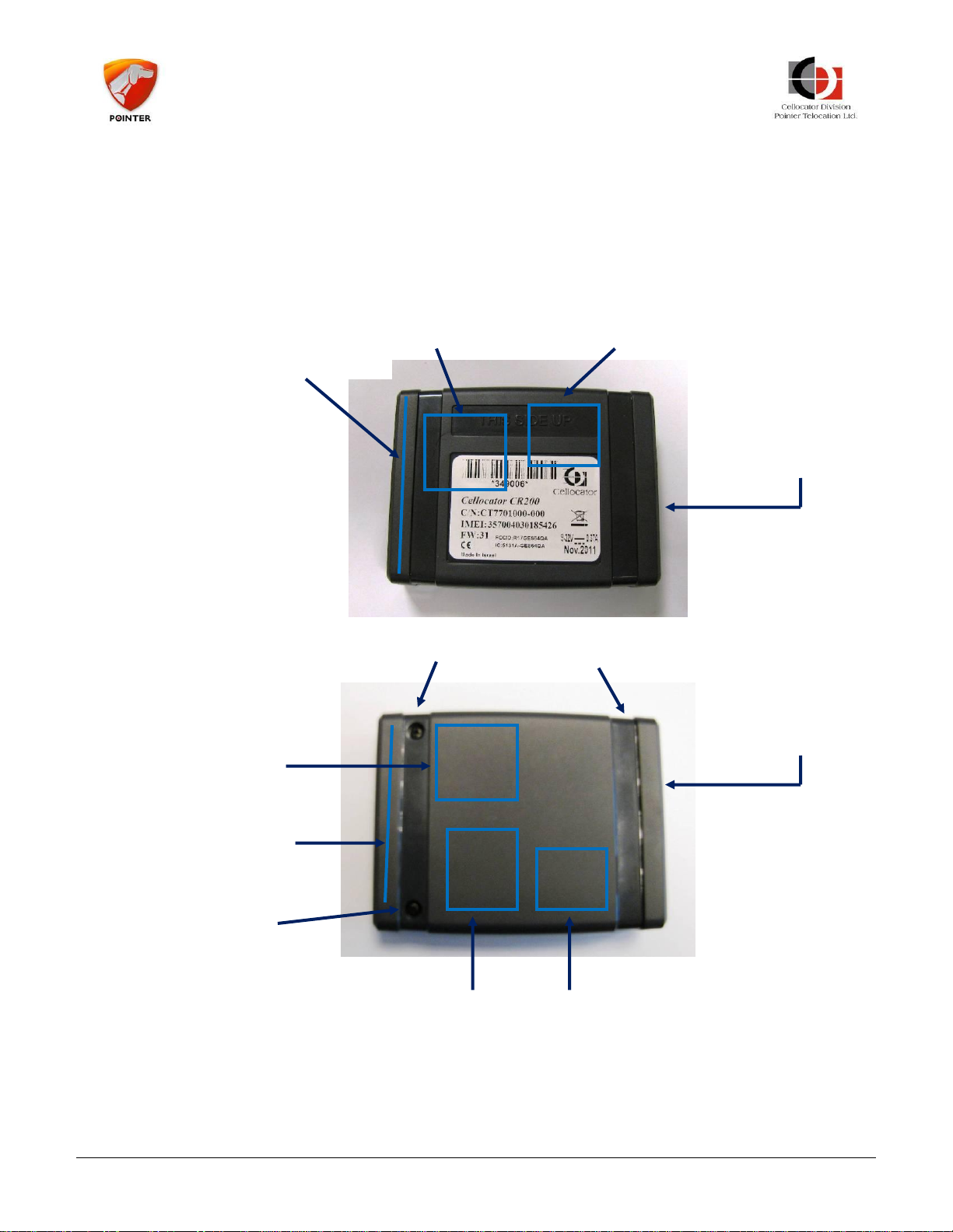
2.1 Introducing the Main Elements of the CR Family Unit
Figure 1 below shows the main elements of a CR unit.
Figure 1: Main Elements of a CR unit
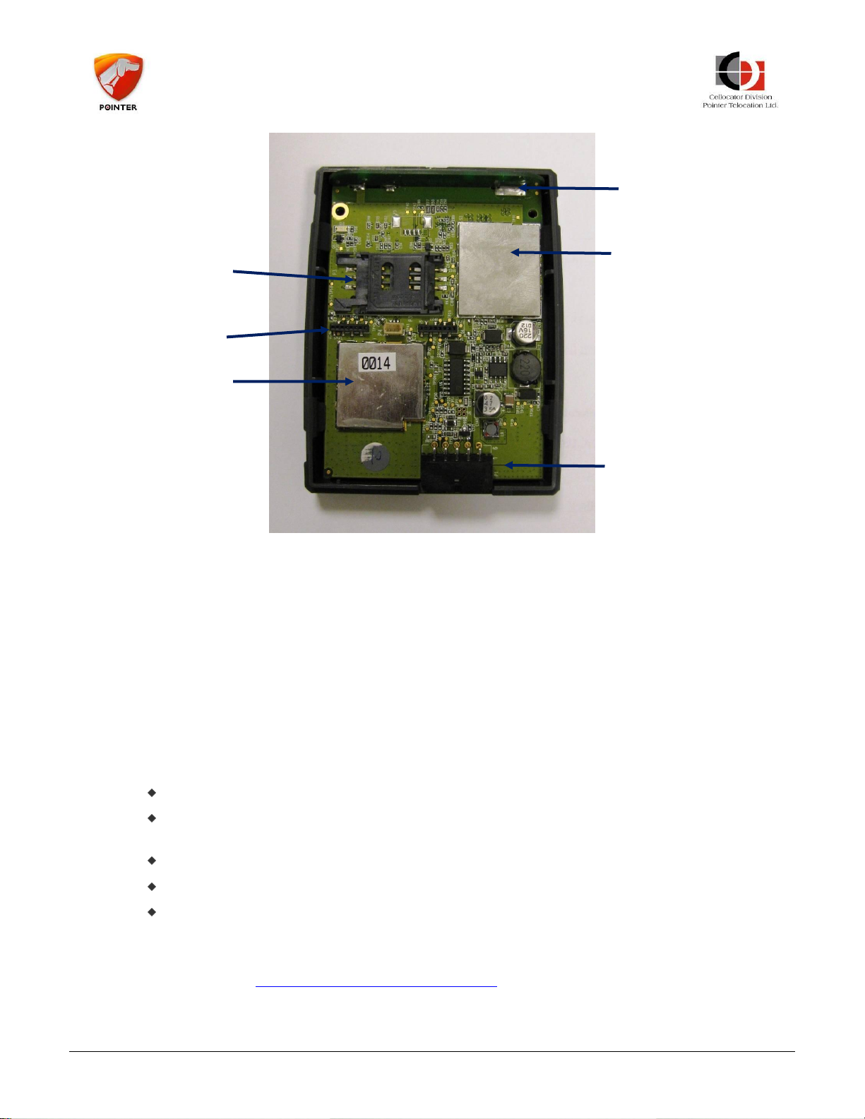
Figure 2 provides an internal view of the CR unit and all relevant elements.
CR Family Hardware Installation Guide Page 6 of 30
Copyright © 2016 by Pointer Telocation, Ltd.
Page 7
CR Family Hardware
Installation Guide
Processor
SIM Holder
GPS Module
Jtag and Debug
interface
Connector
(10 pins)
GSM Antenna
Figure 2: CR unit – Internal View
2.2 CR Family Unit Types
The CR Family includes the CR-300 and CR-300B. The CR variants are advanced
integrated GPS/GPRS units designed for fleet management and SVR applications. The unit
also includes a GNSS receiver and a 32-bit processor and memory providing storage for
generated events.
The CR-300B also includes a battery which provides a better solution for SVR applications.
2.3 CR Family Harnesses
The CR units support the following harnesses:
711-00276 CR Six wires main harness.
711-00301 CR Family 6 Wires mold Harness. The harness is replaced by the
711-00331 CR Family 7 Wires mold Harness
711-00280 CR Family Fuse Harness
711-00331 CR Family 7 Wires mold Harness
711-00328 CR Family 10 Wires mold Harness
This document explains in detail how to use the 711-00328 CR Family 10 Wires mold
Harness Kit for proper installation.
Please refer to Cellocator Fuse Harness Overview for installation instructions for the Fuse
Harnesses.
CR Family Hardware Installation Guide Page 7 of 30
Copyright © 2016 by Pointer Telocation, Ltd.
Page 8

CR Family Hardware
Installation Guide
-------------------------------------------------------------------------------------------
IMPORTANT:
The CR unit must be protected by means of a 3A fast blow fuse. The fuse should be
installed either between Power Input (Pin 1) and the vehicle protected power line.
The CR unit must be protected by means of PTC for safety certification compliance.
The PTC should support Resettable Fuse 60V and Imax=40A. It should be installed
between Power Input (Pin 1) and the vehicle protected power line.
These means of protections are supported by the by the fuse attached to the
harnesses provided by Cellocator.
It is the installer responsibility to provide these means of protection if the fuse
provided by Cellocator is not used.
-------------------------------------------------------------------------------------------
CR Family Hardware Installation Guide Page 8 of 30
Copyright © 2016 by Pointer Telocation, Ltd.
Page 9
CR Family Hardware
Installation Guide
Name/Part
Number
Description
Picture
Cellocator
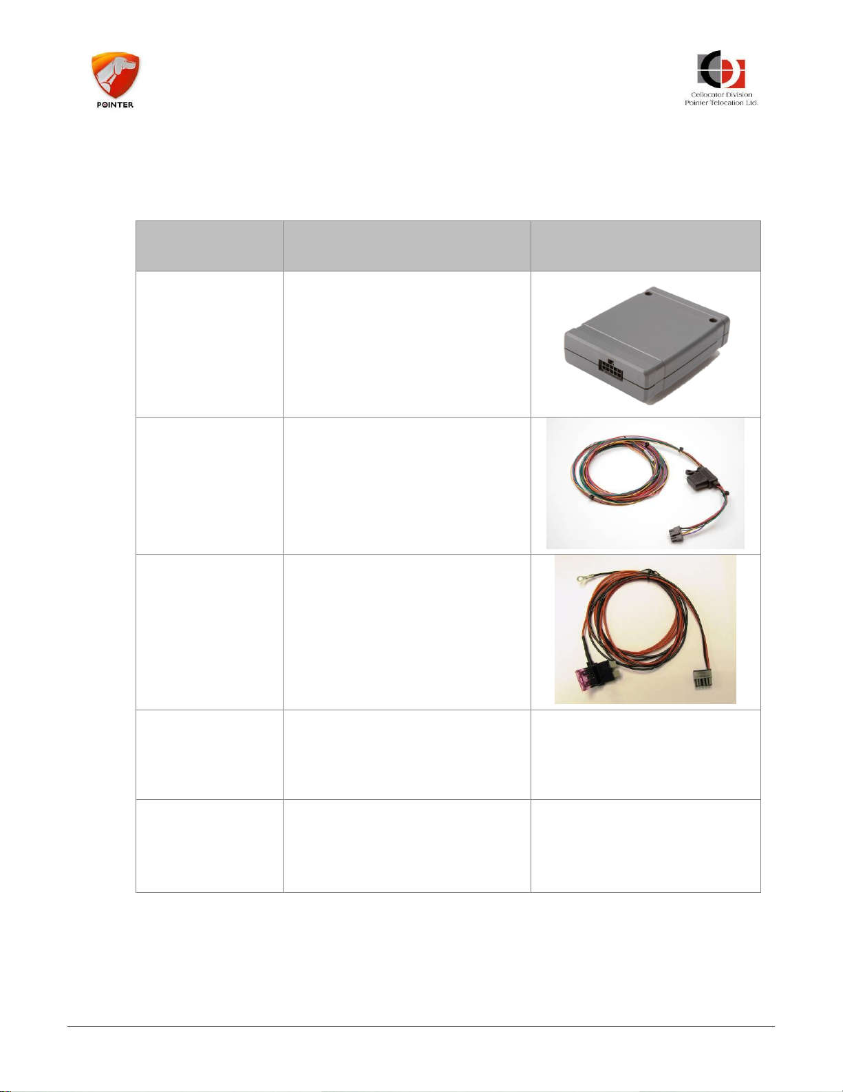
CR Family Unit
CR unit. Includes built in GSM
modem and GPS/GNSS receiver.
The CR B models also include a
battery.
Vehicle harness
PN 711-00276
Six wires harness for vehicle
installation.
CR two wires
Fuse Harness
PN 711-00280
Two wires fuse harness for
power only fast installation.
CR Family 7
Wires mold
Harness
PN 711-00331
7 wires Harness, which supports
the CR Family Protector.
CR Family 10
Wires mold
Harness Kit
PN 711-00328
10 wires harness, which supports
all CR300 interfaces.
2.4 Overview of the Hardware Installation Elements
The CR Hardware Installation requires the items listed in Table 1.
Table 1: CR Hardware Installation Elements
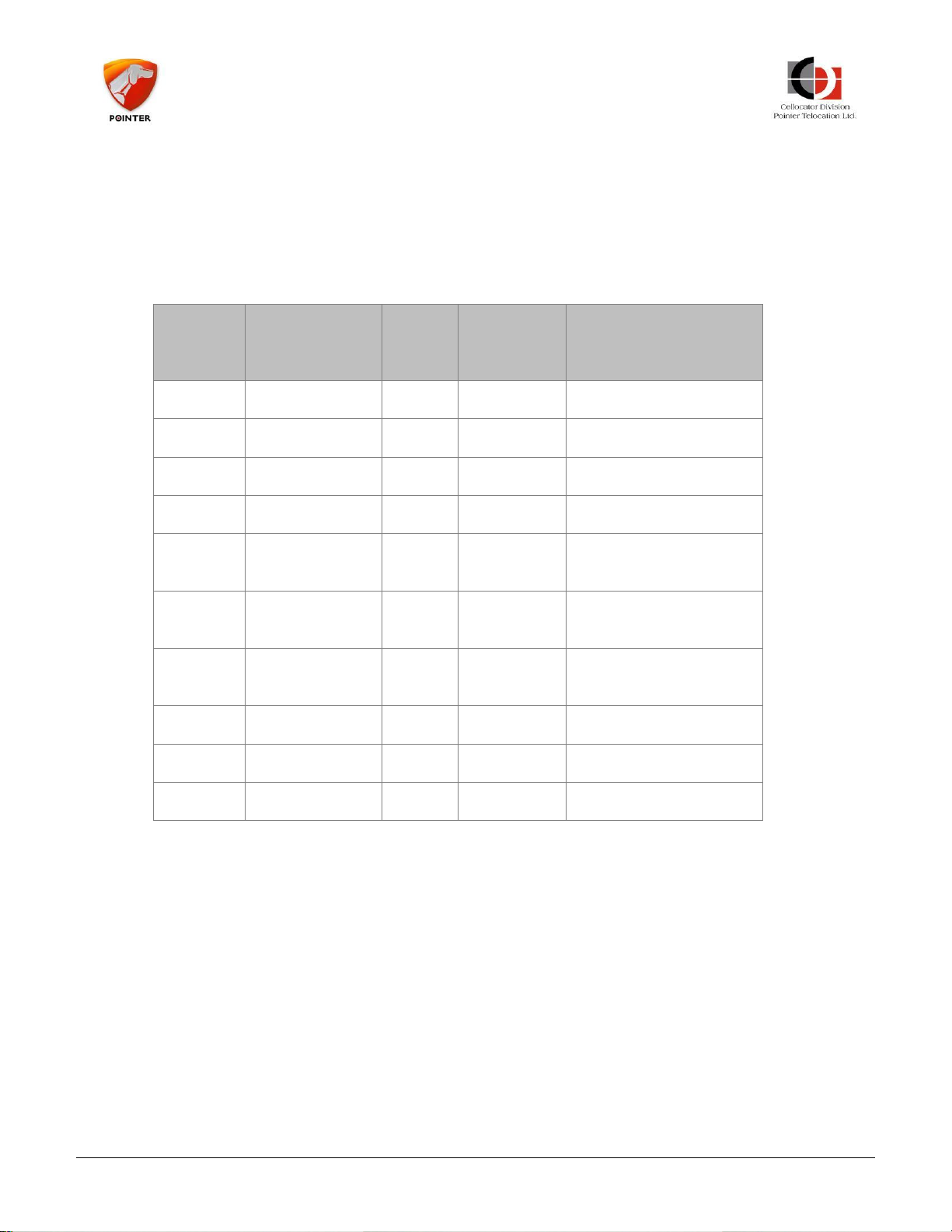
2.5 CR 10 wires Harness (PN 711-00328)
CR Family Hardware Installation Guide Page 9 of 30
Cellocator provides the 712-00328 CR Family 10 Wires mold Harness mainly where serial
interface (pin 7&8) or Dallas (pin 10) interfaces are required. In other cases the 71100331 CR Family 7 Wires mold Harness can be used.
Copyright © 2016 by Pointer Telocation, Ltd.
Page 10
CR Family Hardware
Installation Guide
Wire
Number
Name
Wire
Color
CR Unit
Pin
Number
Function
W1
Main Power
Red
1
Main Power
W2
GND
Black
6
Ground
W3
Ignition
Violet
4
Ignition
W4
SHOCK
Yellow
9
General Purpose Input
W5
LED
Green
2
General Purpose
output or LED
W6
Global Output
Brown
3
General Purpose
output.
W8
DOOR
Pink
5
General Purpose
output.
W9
DALLAS
Grey
10
1-Wire interface
P2(2)
TX 7
Serial TX
P2(3)
RX 8
Serial RX
The harness is made up of colored 22AWG wires, 1.2 meters long, utilizing a 10-pin
connector that links to the CR unit and a 4 pin connector for the serial interface. A fuse
holder with 3A fuse and PTC Resettable Fuse 60V and Imax=40A is attached to the
harness.
The following table provides a description of the harness. Additional information can be
found in the relevant sections dealing with the harness installation instructions.
Table 2: CR 10 Wires Harnesses description
CR Family Hardware Installation Guide Page 10 of 30
Copyright © 2016 by Pointer Telocation, Ltd.
Page 11

CR Family Hardware
Installation Guide
3 Preparing for Installation
The following section explains the pre-installation steps you should perform before
installing the CR unit.
3.1 Pre-Installation Information
-------------------------------------------------------------------------------------------
IMPORTANT:
- You must be a certified technician and qualified to install the Cellocator unit.
- Please make sure you have the correct documentation for the devices you install. The
devices and documentation change frequently, which may impact the installation
procedures.
- Make sure you know the installation procedures and restrictions of the vehicle; consult
with the dealer or manufacturer to get any specific instructions. These may refer to
locations in the vehicle where you can install the device, connections to the electrical
system, use of fuses, etc. Not following these instructions and restrictions may create
false alarms and malfunctions in the vehicle systems and may even void the vehicle
warranty.
- Modern vehicles have many computerized systems that may be sensitive to radio
transmissions from the device you install and may also generate interferences to the
device. Carefully read the manufacturer’s instructions and restrictions regarding these
systems.
-------------------------------------------------------------------------------------------
3.2 Safety
-------------------------------------------------------------------------------------------
WARNING:
- Use protective goggles during the installation.
- Disconnect the vehicle battery during installation. Working on live wires can be
dangerous and can, for example, result in airbags inflating or fuses burning out. Some
devices (e.g. the radio) may require reprogramming after a power disconnect.
- Do not install any wires (except the fuel sensor wires) near the fuel system or fuel
pipes. Make sure you never work near the fuel system with the battery connected.
- Installation in vehicles with computerized systems may have unexpected results.
Please consult with your local car dealer before performing any vehicle OEM invasive
installation.
- Do not disconnect any connectors in the vehicle while the ignition switch is turned on.
This may result in damage to sensitive vehicle subsystems.
- Use special care when handling the backup battery of the Cellocator unit. Refer to
Battery Handling Procedure for Cellocator Units for details.
- Review the important safety notes in section 5.3 Harness Power Installation
Specifications.
CR Family Hardware Installation Guide Page 11 of 30
Copyright © 2016 by Pointer Telocation, Ltd.
Page 12
CR Family Hardware
Installation Guide
- There is a serious risk of battery explosion if a battery of incorrect type is used in the
device.
- Dispose used batteries in accordance to applicable regulations.
-------------------------------------------------------------------------------------------
3.3 Tools and Equipment Required
To correctly install the device and accessories, you may need the following equipment and
tools:
A wire cutter
Pliers (2 sizes may be required)
Screwdrivers of several sizes
Professional insulation remover
Crimping tool for wire lugs
Digital multi-meter
Utility (razor) knife
Flash light or other light source
Tools to remove the vehicle trims (panel popper, sockets, ratchet etc.)
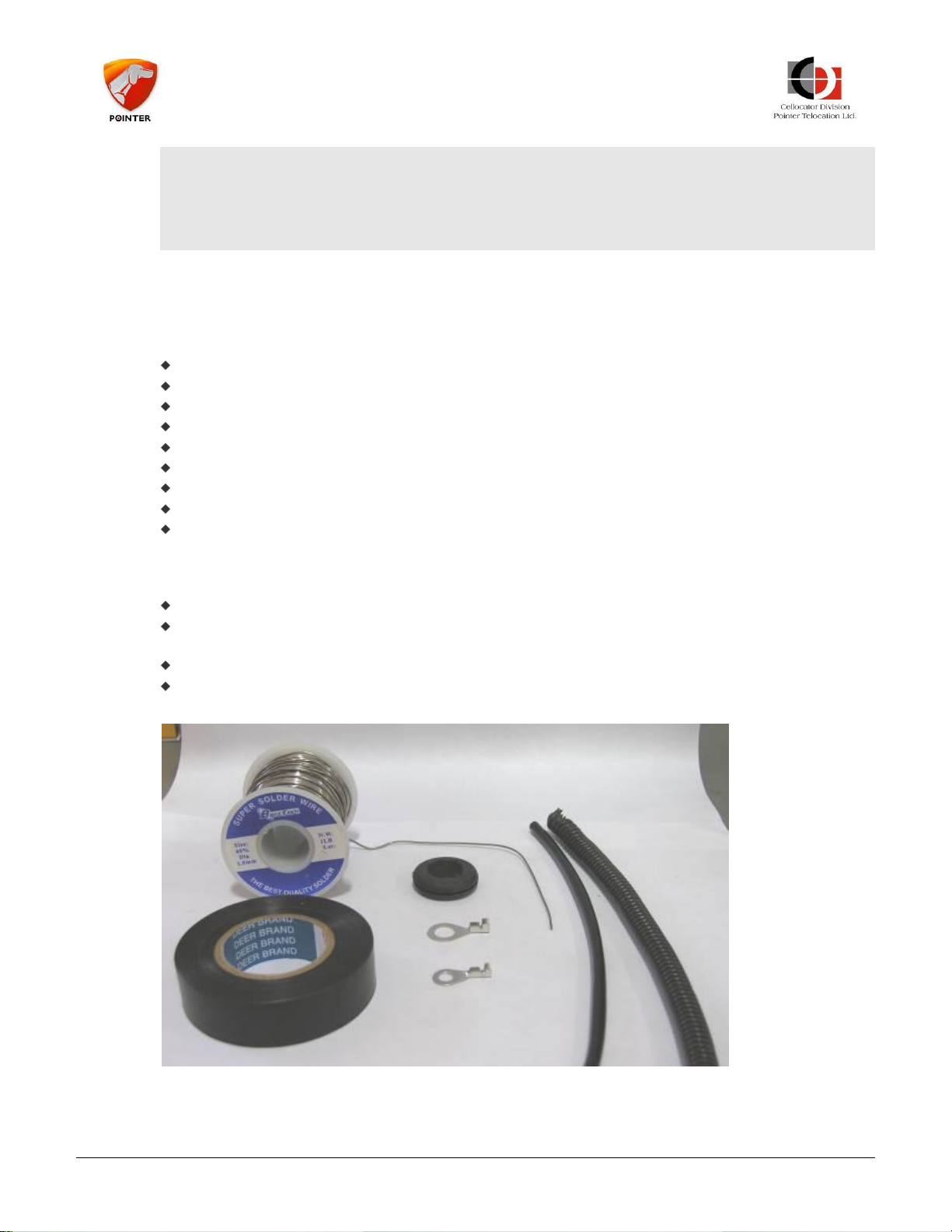
3.4 Materials Required
Soldering wire
Insulation tape of good quality (which can withstand the high temperatures in a
vehicle on a hot summer day)
Wire lugs with star washers
Grommets, plastic tubes – as needed
Figure 3: Materials Required
CR Family Hardware Installation Guide Page 12 of 30
Copyright © 2016 by Pointer Telocation, Ltd.
Page 13
CR Family Hardware
Installation Guide
3.5 Installation Best Practices
This section lists the Best Practices you should follow for installing the unit.
Put protective covers on the front seats before you start the installation, to prevent
damage to the upholstery. Use other covers for sensitive areas in the vehicle (LCD
display, radio etc.).
Do not use a cutter to expose the conductor in the wire, use a professional insulation
remover that will not damage the delicate copper conductors.
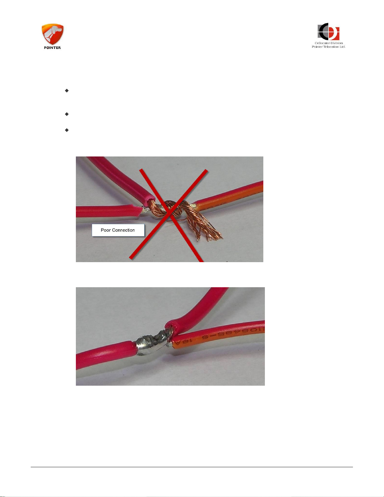
Use soldering for all of your connections. Do not connect a new wire to an existing
wire (without soldering it) to make a connection. These types of connections, as shown
in the following picture, are typically of poor quality and sooner or later will disconnect
or will make intermittent connections.
Figure 4: Poorly Soldered Connection
A good connection has to be properly soldered, as in the picture below:
Figure 5: Correctly Soldered Connection
CR Family Hardware Installation Guide Page 13 of 30
Copyright © 2016 by Pointer Telocation, Ltd.
Page 14
CR Family Hardware
Installation Guide
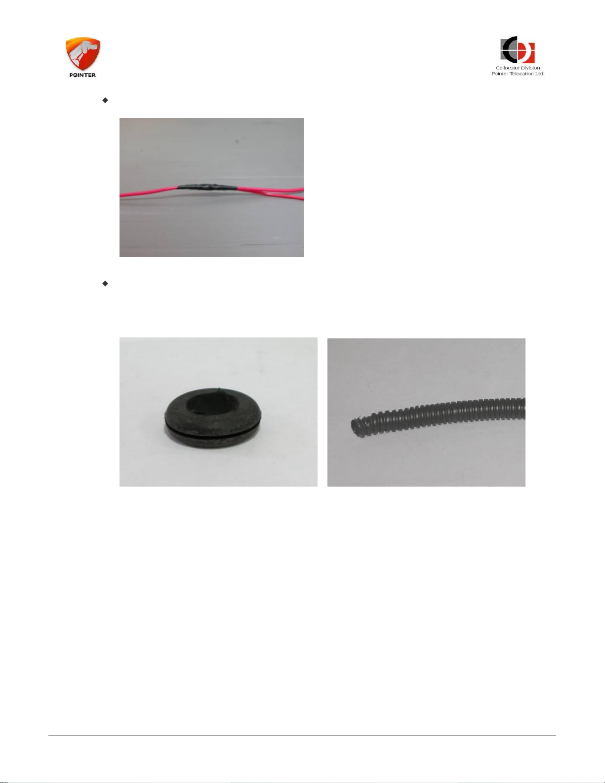
Isolate the connection with a plastic cover or a professional insulation tape so that no
wires remain exposed.
Figure 6: Isolate the Connection
Use existing wire ducts, openings and holes to pass wires between different areas in
the vehicle. Do not punch or drill new openings or holes to pass wires between
different zones in the vehicles, as this will create permanent damage to the vehicle,
and other wires or pipes. Make sure the opening is properly protected by a grommet
or a plastic sleeve to prevent damage to the wires.
Figure 7: Preventing damage to the wires
CR Family Hardware Installation Guide Page 14 of 30
Copyright © 2016 by Pointer Telocation, Ltd.
Page 15
CR Family Hardware
Installation Guide
Use only a voltmeter or LED based test lamp (that uses a very small current) to test
the existence of voltage in a wire or accessory. Do not use a regular test lamp to test
the existence of voltage in a wire. These testers take quite a lot of current and may
damage the equipment in the vehicle (for example it can trigger an airbag or damage
a communication bus).
When you want to test the voltage on a wire, do not expose the existing wires or use a
sharp edge to make an electrical connection to a wire through the insulation sleeve
around it. Make the connection at the end of the wire, near the connector.
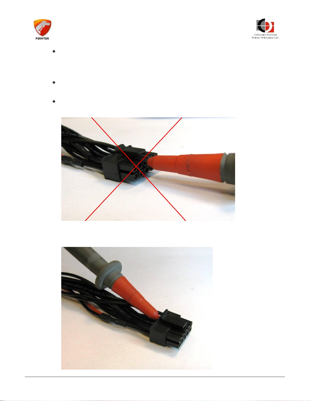
Do not insert the multi-meter probe tip into the female pin in the connector. This may
widen it and prevent a proper connection when the male connector is plugged in.
Figure 8: Incorrect probe insertion
The correct way to connect the probe of a voltmeter or tester to the connector is
shown below:
CR Family Hardware Installation Guide Page 15 of 30
Copyright © 2016 by Pointer Telocation, Ltd.
Page 16
CR Family Hardware
Installation Guide
Figure 9: Correct connection
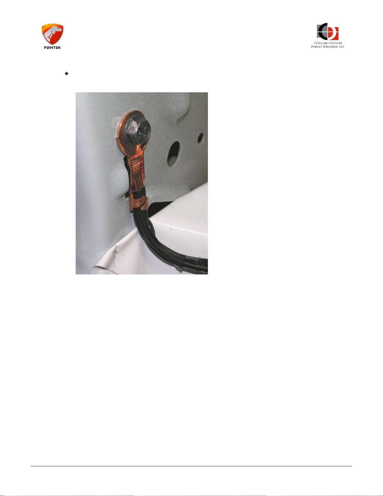
To connect the negative power wire of the device, connect a lug properly crimped (or
soldered) to the negative wire of the device (pin 3 in the 20 pin connector) and screw
it to the chassis using an existing screw. Ensure the connection is good and stable.
Figure 10: Connecting negative power wire
CR Family Hardware Installation Guide Page 16 of 30
Copyright © 2016 by Pointer Telocation, Ltd.
Page 17

CR Family Hardware
Installation Guide
After all wires are connected, use plastic straps (cable ties) or insulation tape to secure
all the wires and cables to fixed elements in the vehicle (such as existing stable cables,
metal parts or other fixed parts of the vehicle, but not parts that are removed during
regular vehicle service). Loose cables and wires may cause irritating noises while the
vehicle is in motion.
Do not lay cables and wires on the floor of the vehicle where people can step on them.
Always route the cables in areas where they will not be stepped on or otherwise
damaged by other activities.
All wires and cables should be hidden.
Make sure the device is receiving power with a properly fused connection. The fuse is
supplied with the harness.
To attach the device to its location use a thick, two sided, adhesive tape, between the
device and the fixed support and then use two plastic straps (cable ties) to secure the
device to its location. Make sure the device is well positioned and will not become
loose (it may either fall or create irritating noises if not properly secured).
Figure 11: Attaching the device
When you finish your work, clean the vehicle and return all the items you removed
into their original positions, using all the original screws and connectors.
Test the functioning of all the vehicle systems: they should all perform as is before you
installed the device.
Test the connectivity of the device with the system server to ensure proper operations.
CR Family Hardware Installation Guide Page 17 of 30
Copyright © 2016 by Pointer Telocation, Ltd.
Page 18
CR Family Hardware
Installation Guide
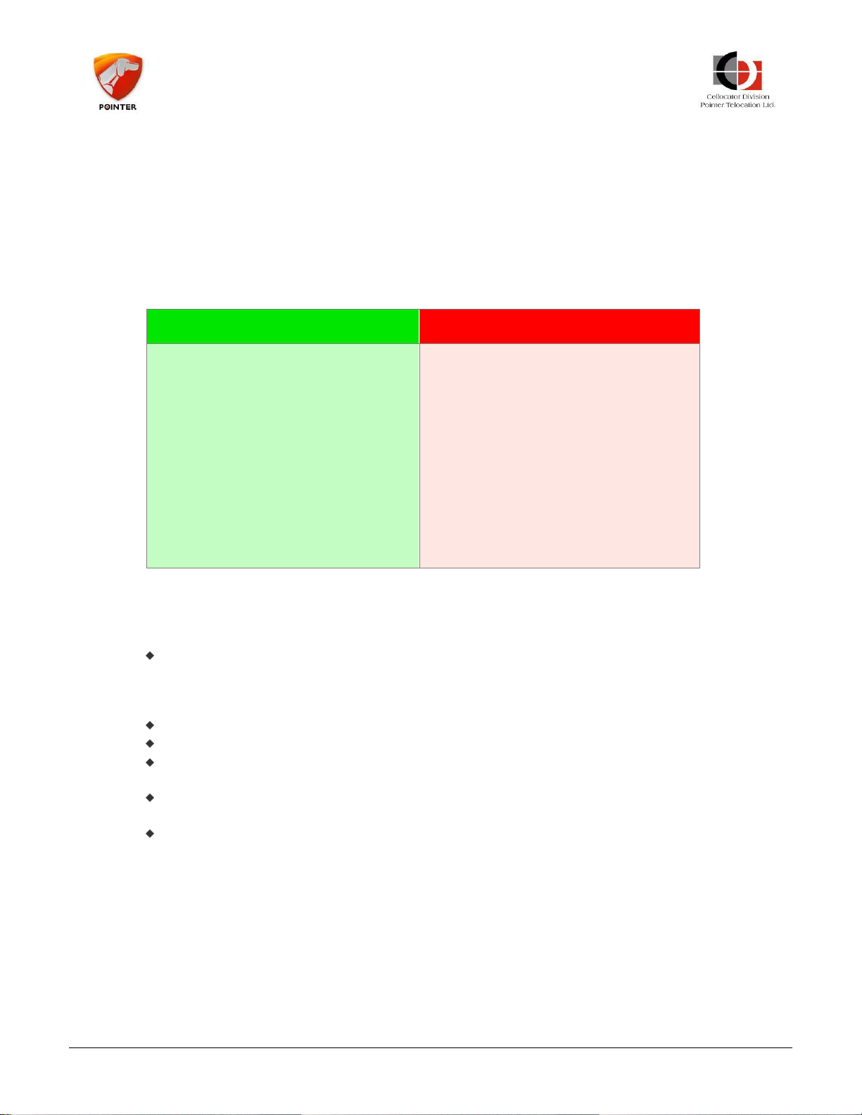
You can install the device in…
Do NOT install the device in…
Passenger cars of all types
Light and heavy trucks
Buses
Motorcycles
Snowmobiles
Tractors
Boats, jet skis and other
marine units
The carriage of a semi-
trailer or full trailer
Containers and other assets
Installation in these environments
requires special protection materials
and is not covered in this guide.
4 CR Unit Installation Instructions
Before installing, please read the Pre-Installation Information and Safety sections.
4.1 General
The following table describes the type of vehicle in which you can install the device, and
which vehicles you should NOT install it in.
Table 3: Compatible and incompatible Vehicles
4.2 Location of the Device in the Vehicle
When locating the device in the vehicle please consider the following:
The device is not weather proof. It is specified as an IP40 device and thus is not
immune to penetration of water, rain, dust, dirt and smoke. If you need special
solutions to special environmental conditions, please consult your customer support or
account manager.
The device receives and transmits radio energy in the GSM frequency bands.
The device receives radio energy in the GPS frequency band from GPS satellites above.
In SVR applications it is recommended to conceal the device so that it will not be easy
for thieves to find and disconnect it.
The device will not function well in excessive temperatures (see the specifications for
details).
The device requires minimal maintenance.
The following table describes both the preferred locations for installing the device and a
list of locations where the device should NEVER be installed.
CR Family Hardware Installation Guide Page 18 of 30
Copyright © 2016 by Pointer Telocation, Ltd.
Page 19

CR Family Hardware
Installation Guide
Preferred location in vehicle…
NEVER install the device…
Behind the dashboard.
In or behind the glove
compartment.
Anywhere in the front of the
passenger compartment under the
console and above the leg space.
In a protected area under the
driver’s seat.
Less preferable: in the trunk of a
passenger car (the radio signals
penetrate the trunk mostly through
the rear window and rear seat: you
may have to find the best location
and orientation through trial and
error).
Outside of the passenger
compartment or vehicle trunk.
In the engine compartment.
Inside the bumpers/fenders.
Behind the front lights.
In air ducts.
Close to airbags.
Under the vehicle.
Under the roof of the vehicle.
In a location susceptible to rain or
water.
Inside a metal pocket or box.
In the loading area of a truck or
pickup.
Near the fuel tank.
Near the wheels.
Near any radio transmitter or its
antenna.
Table 4: Where to install the device
Some vehicles, (for example, some Renault Kangoo models) have solar windows with
transparent metallic coating that blocks the solar radiation. Unfortunately they also block
most of the radio radiation required for the GPS reception. In these cases, you may
consult with the dealer about the best locations for the device. If such support is not
available, use trial and error to find a reasonable place for the device.
Locating the device in a prohibited location may significantly affect the functionality of the
device, will shorten its lifetime and will create malfunctions and expensive service calls.
Note that the space inside the doors is not a very good location. It is more exposed to
outside temperatures and will force you to install the device vertically and not
horizontally. If you have to install the device there make sure to locate the device in the
area that is not exposed to rain and water and has reasonable reception.
CR Family Hardware Installation Guide Page 19 of 30
Keep at least 30 cm between the device and any computerized system in the vehicles, to
avoid mutual interference.
Do not install the device or any wire near a moving or rotating part of the vehicle.
Copyright © 2016 by Pointer Telocation, Ltd.
Page 20
CR Family Hardware
Installation Guide
4.3 Device Orientation
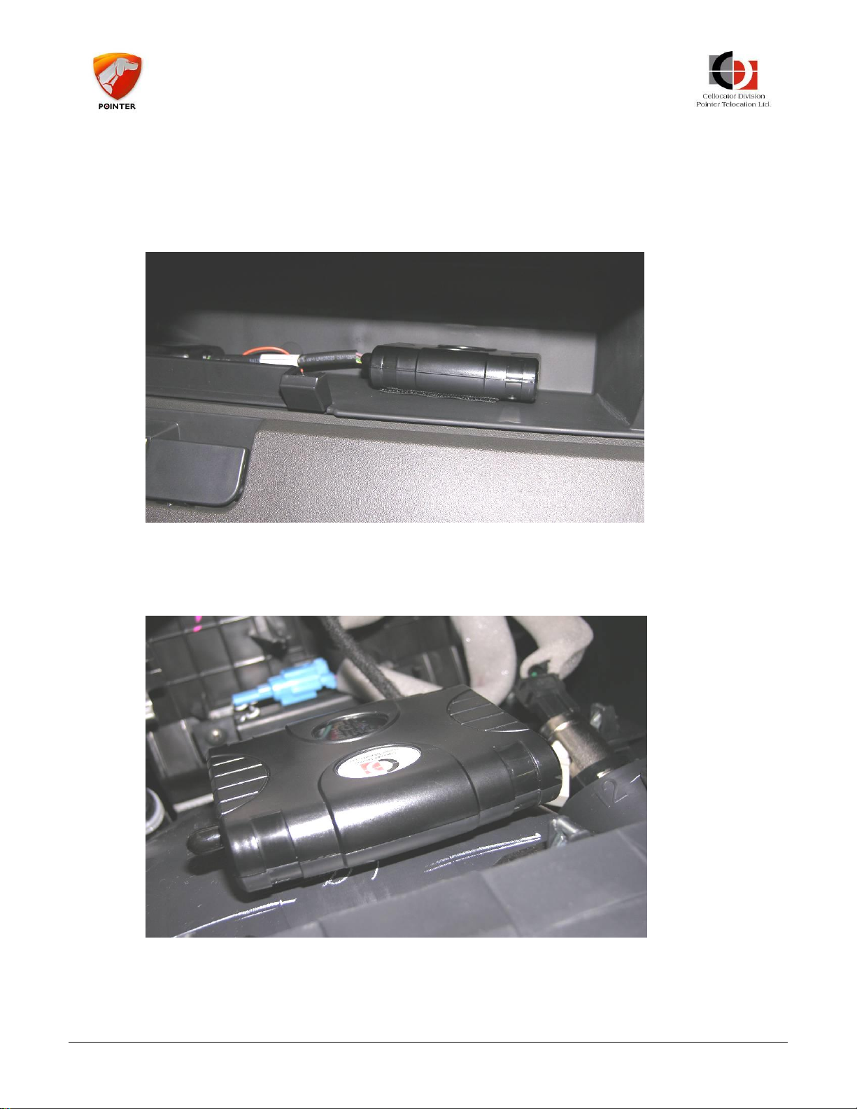
The device uses the internal GPS antenna that should have a good GPS reception and
consequently the device direction (orientation) is important. To ensure this, the side
marked “This side Up” should face upwards and should have a clear sky view,
unobstructed by any metal or shields. Plastic and glass do not usually affect reception.
Figure 12: Device orientation
The GPS receiver in the device is sensitive enough to allow reasonable reception even in
cases where the top side of the device (marked 'This Side Up') deviates up to 60 degrees
from the ideal direction.
Figure 13: Ensuring the device is located with 30cm free radius
In any case, this side should have a free space (with no metal obstructions) of
approximately 30cm radius, with the device in the center of it.
CR Family Hardware Installation Guide Page 20 of 30
Copyright © 2016 by Pointer Telocation, Ltd.
Page 21
CR Family Hardware
Installation Guide
Securing
screws
4.4 Installing the SIM Card
To install the SIM card, perform the following steps:
------------------------------------------------------------------------------------------------
NOTE: Make sure that your SIM card PIN is identical to the PIN programmed in the unit,
or disabled. The default value of the unit PIN code is 1234. If the SIM PIN and the unit pin
differ, insert the SIM card into a regular cellular phone and either change its PIN to the
unit PIN (1234) or disable it.
SIM PIN protection and value (locking the SIM) can be activated automatically providing
PIN synchronization between the SIM and the unit.
------------------------------------------------------------------------------------------------
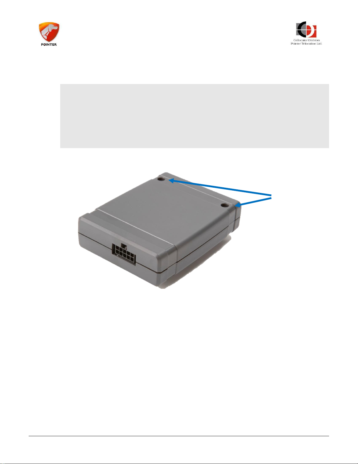
1. Remove the back cover of the CR unit by removing the two securing screws.
CR Family Hardware Installation Guide Page 21 of 30
Figure 14: Back of Unit Showing Two Securing Screws
Copyright © 2016 by Pointer Telocation, Ltd.
Page 22
CR Family Hardware
Installation Guide
SIM Holder
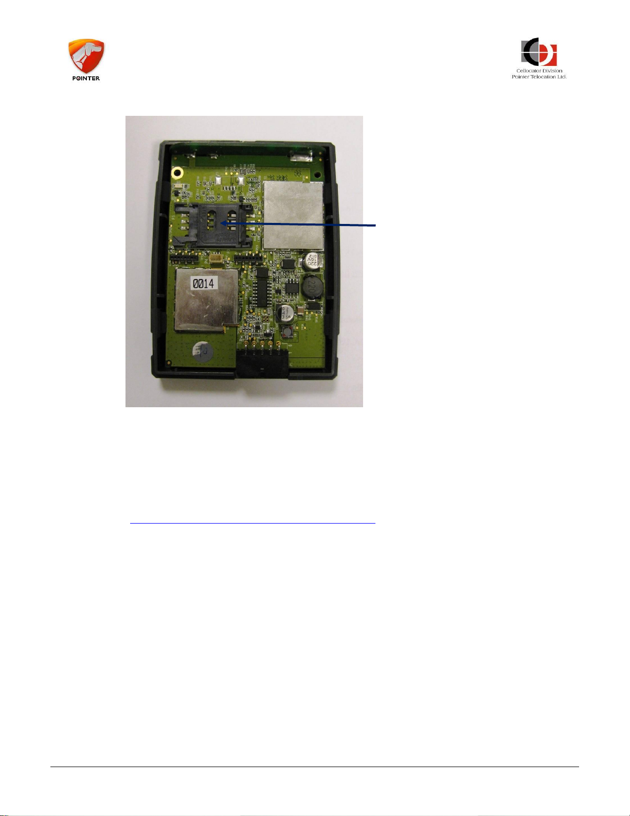
2. Gently slide t h e SIM card into the SIM holder as shown below.
Figure 15: Inserting the SIM Card
3. Close the unit, insert the 2 screws and tighten to a torque of 3.5 kgf-cm (kilogram
force per centimeter) which is approximately 0.35 Nm (Newton per Meter).
4.5 Installing the Battery in CR B Models
See Battery Handling Procedure for Cellocator Units for information about the battery and
its handling instructions.
If you received the device without the battery or you received the device with the battery
inside but not connected, please open the device, connect the battery cable to the onboard connector and close the device. When you connect the vehicle battery to the
device, the device will start working normally. Do not reverse the order of connections;
the correct order is to first connect the battery then connect the vehicle power to the
device.
CR Family Hardware Installation Guide Page 22 of 30
Copyright © 2016 by Pointer Telocation, Ltd.
Page 23
CR Family Hardware
Installation Guide
GSM
Monitoring
Zone – 3
seconds
Interval –
1 second
GPS
Monitoring
Zone – 3
seconds
Interval –
5 seconds
GSM
Monitoring
Zone – 3
seconds
Interval –
1 second
GPS
Monitoring
Zone – 3
seconds
5 Harness Installation Instructions
5.1 Harness Outputs Installation Specifications
5.1.1 General
The following information is common for all the outputs:
All Outputs are Open Collector type and can sink up to 300 mA continuous.
External devices (not OEM) that consume more than 300mA should be powered by a
relay. In such cases, the output implementation requires an external relay.
The outputs can be activated or deactivated from the control center using the OTA command.
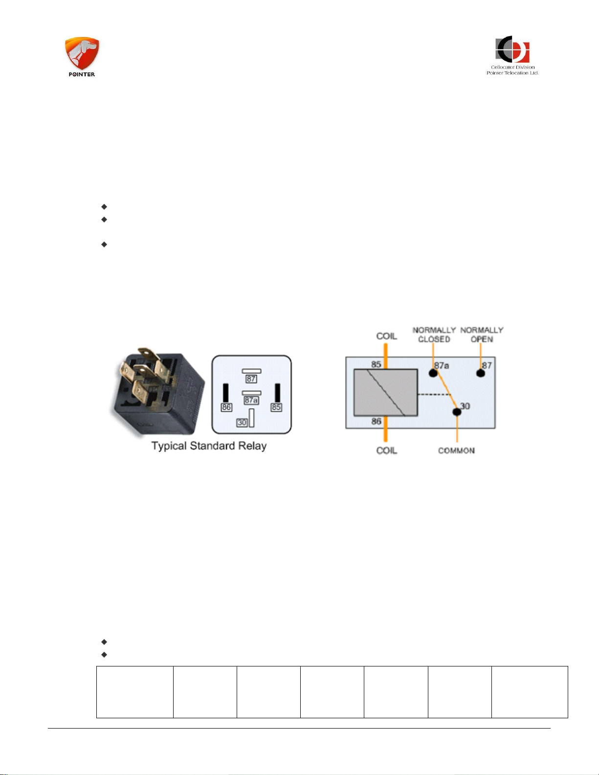
5.1.2 Relay Pin-Out
A relay is utilized to serve as an adaptor between the harness output and a device in the
vehicle (immobilizer, siren, etc.). The following figure shows the pin-out location of the
relay. The pin numbers are also printed on the Relay itself.
5.1.3 LED Output
CR Family Hardware Installation Guide Page 23 of 30
The relay figure and the pins numbers are used when describing harness outputs installations.
The harness LED green wire is connected to the CR unit pin no. 2. The LED itself should
be connected to the LED wire and vehicle Battery. The LED provides an indication of
system status. A full description of LED indications in the CR unit is presented below.
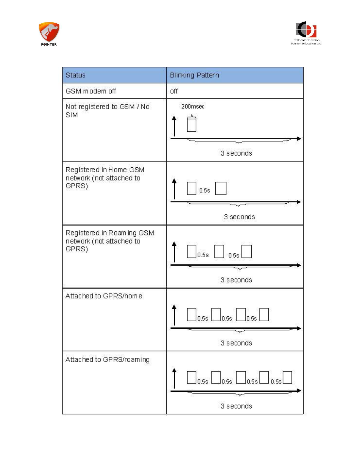
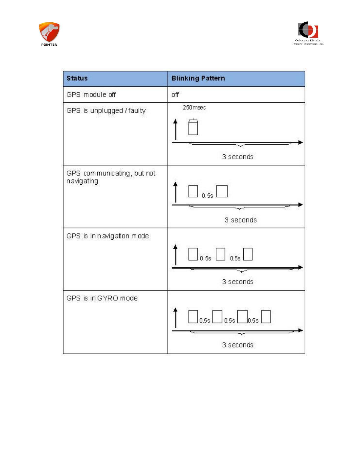
The LED output can be used as general purpose open collector output, if configured accordingly.
The LED output involves a sophisticated blinking pattern which provides monitoring status
of both GPS and GSM status. The blinking pattern is constructed of repeated cycles of two
blinking zones each. The first zone represents GSM functionality and the second zone,
GPS functionality.
Each zone lasts for 3 seconds with a 1-second LED off interval between them.
A 5 second LED off interval separates each cycle.
Figure 16: Relay Pin-Out
Copyright © 2016 by Pointer Telocation, Ltd.
Page 24
CR Family Hardware
Installation Guide
5.1.3.1 GSM Monitoring Zone Definition
CR Family Hardware Installation Guide Page 24 of 30
Copyright © 2016 by Pointer Telocation, Ltd.
Page 25
CR Family Hardware
Installation Guide
5.1.3.2 GPS Monitoring Zone Definition
5.1.4 Global Output
The harness Global Output brown wire is connected to the CR Pin no. 3.
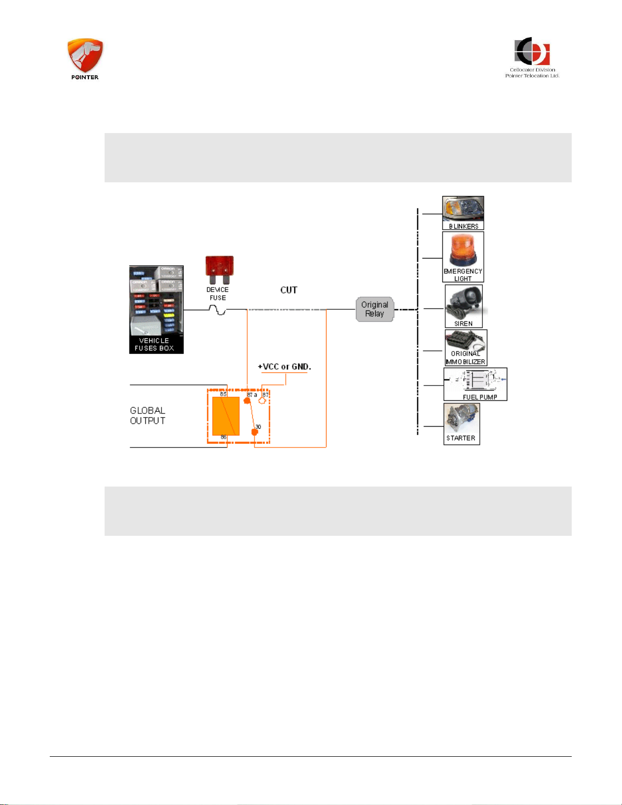
The output functionality is defined according to programming parameters (PL). In most
cases, the CR unit uses this output as a global output, allowing activation/deactivation of
several devices, such as blinkers, parking lights, an additional siren, etc. In this case the
output shall be connected to the required device as shown in the following installation
diagram.
CR Family Hardware Installation Guide Page 25 of 30
Copyright © 2016 by Pointer Telocation, Ltd.
Page 26
CR Family Hardware
Installation Guide
It can be activated/deactivated by an OTA command from the control center. The
following illustration provides the Global Output installation.
---------------------------------------------------------------------------------
NOTE: The original wire must be cut and the relay connected between the original relay
and the vehicle power.
---------------------------------------------------------------------------------
Figure 17: Global Output Installation Diagram
---------------------------------------------------------------------------------
NOTE: Configuration can be programmed to support Immobilizer functionality on each
one of the two outputs.
---------------------------------------------------------------------------------
5.2 Harness Inputs Installation Specifications
5.2.1 Global Purpose Input (Shock)
The harness Global Purpose Input (Shock) yellow wire is connected to the CR unit pin no.
9 and used for general purpose input.
5.2.2 Door Input
The harness Global Purpose Input (Door) pink wire is connected to the CR unit pin no. 5
and used for general purpose input.
5.2.3 Ignition Input
The harness Ignition Input Violet wire is connected to the CR unit pin no. 4 and should be
connected to the ignition switch (in the ON position).
CR Family Hardware Installation Guide Page 26 of 30
Copyright © 2016 by Pointer Telocation, Ltd.
Page 27

CR Family Hardware
Installation Guide
5.2.4 Dallas Input
The harness Dallas Input gray wire is connected to the CR unit pin no. 10 and used for
Driver Identification.
5.3 Harness Power Installation Specifications
5.3.1 Main Power
The harness Main Power red wire is connected to the CR unit pin no. 1 and should be
connected to the car’s protected power line (12V / 24V) (refer to Installation Drawing,
Section 5.5).
Please note that the battery name or picture used in this document represents practically
the protected power line at the output of the fuse box.
5.3.2 GND
The harness GND black wire is connected to the CR unit pin no. 6 and should be connected
to vehicle ground (at dedicated points) (refer to Installation Drawing, Section 5.5).
-------------------------------------------------------------------------------------------
IMPORTANT:
The CR unit must be protected by means of a 3A fast blow fuse. The fuse should be
installed between Power Input (Pin 1) and the vehicle protected power line.
The CR unit must be protected by means of PTC for safety certification compliance.
The PTC should support Resettable Fuse 60V and Imax=40A. It should be installed
between Power Input (Pin 1) and the vehicle protected power line.
These means of protections are supported by the fuse attached to the harnesses
provided by Cellocator.
It is the installer responsibility to provide these means of protection if the fuse
provided by Cellocator is not used.
The battery name or battery picture used in this document represents practically the
protected power line at the output of the fuse box.
-------------------------------------------------------------------------------------------
5.4 Serial Port Connector
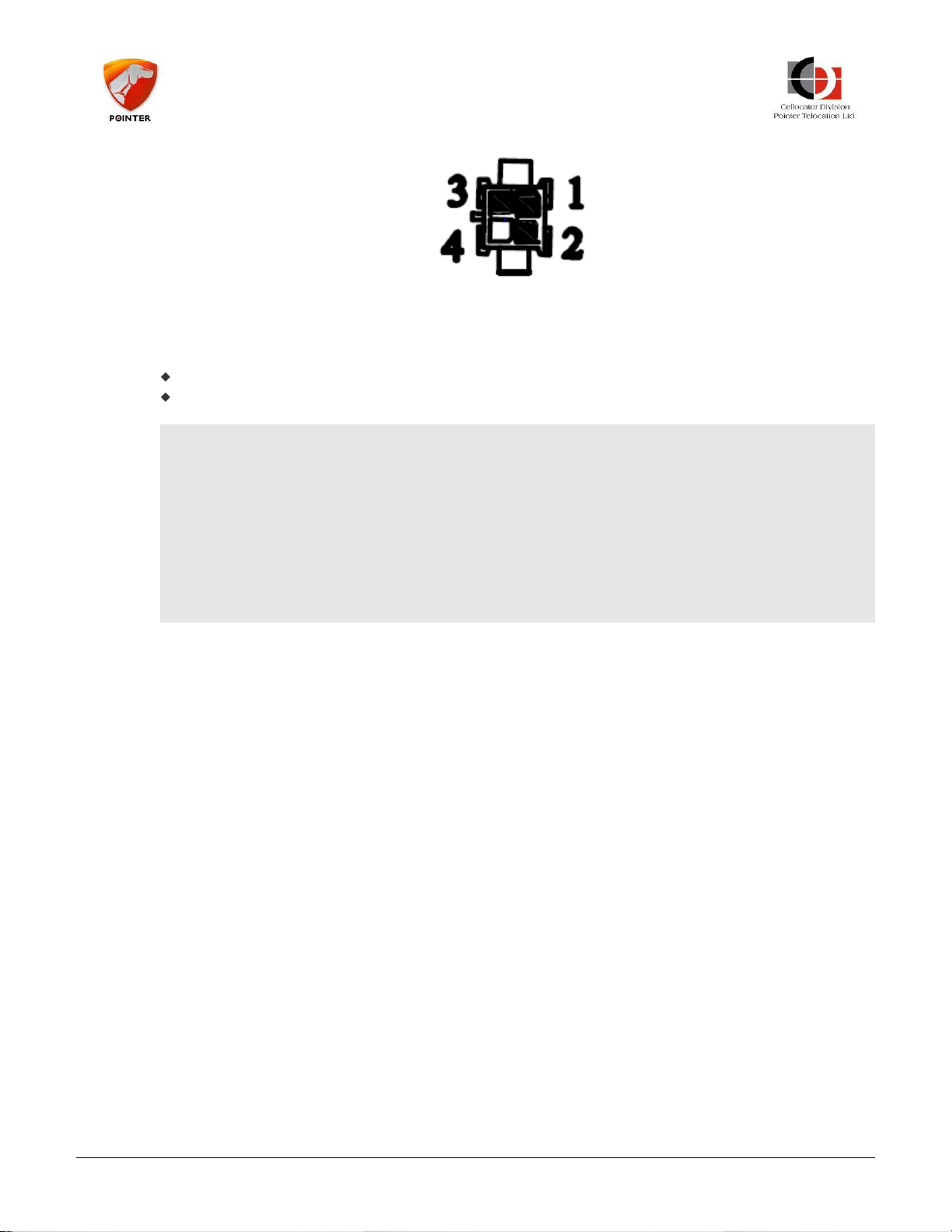
The harness supports a 4 pins connector allowing external devices communication to the
CR unit via its serial interface (CR pins 7 and 8). The connector is illustrated in Figure 18.
CR Family Hardware Installation Guide Page 27 of 30
Copyright © 2016 by Pointer Telocation, Ltd.
Page 28
CR Family Hardware
Installation Guide
Figure 18: Serial Port Connector – Front View
The serial port adaptor connector pin out is:
Pin 2: TX
Pin 3: RX
-------------------------------------------------------------------------------------------
IMPORTANT:
The CR serial interface supports TTL level.
You may connect it to PC USB port for programming utilizing the 711-00251 USB
Communication adapter.
It is the installer’s responsibility to utilize appropriate converter if RS232 levels are
required.
-------------------------------------------------------------------------------------------
CR Family Hardware Installation Guide Page 28 of 30
Copyright © 2016 by Pointer Telocation, Ltd.
Page 29
CR Family Hardware
Installation Guide
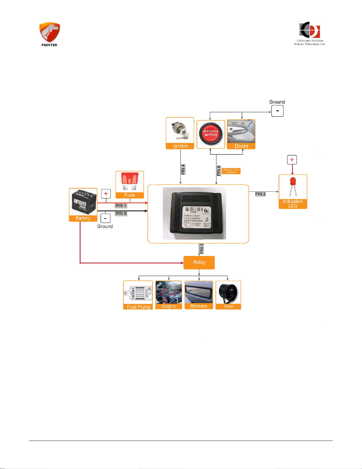
5.5 CR Unit Installation Diagram
The diagram below should serve as a schematic high level installation diagram and not as
a specific detailed installation diagram per vehicle model.
Figure 19: CR Unit Installation Diagram
CR Family Hardware Installation Guide Page 29 of 30
Copyright © 2016 by Pointer Telocation, Ltd.
Page 30
CR Family Hardware
Installation Guide
6 Post-Installation
When you have finished installing and testing the device you have to record the relevant
details. These details will help you or your colleagues to maintain the device in the future.
The best way to do this is to register all the details in an easily accessible application with
a database. This application should be accessible by a PC at the installation location or
even via smartphone. A less efficient solution is an Excel file or even handwritten records.
The details that should be recorded are:
Name of the customer
ID of the vehicle
Type of the device installed
Accessories installed (sensors, harness etc.)
Cables/Harnesses used
Location of the device in the vehicle
Direction and inclination of the device
Name of the installer
Location where the installation took place
Date of installation
Results of installation test/issues found
Results of communication test to the server/issues found
Picture(s) of the installed device, harness and accessories, as installed
Other comments
CR Family Hardware Installation Guide Page 30 of 30
Copyright © 2016 by Pointer Telocation, Ltd.
 Loading...