

Pointer CelloTrack Nano, MultiSense User Manual

CelloTrack Nano
and MultiSense
User Guide
V3.1 5-Oct-2016

CelloTrack nano
Cargo and light asset management
WIRELESS
SENSORS NETWORK
16 PAIRD
MULTISENSE
INTERNAL
SENSORS
VARIED APPS
App
DUAL
TAMPERING
SOUND
TEMPERATURE
LIGHT
MOVEMENT
PRESURE
CELLOTRACK NANO

CelloTrack Nano Delivers
Real Time Cargo & Asset Visibility, Efficiency and Security
• Visibility
Enables real-time awareness of cargo and asset location, condition, problems and delays
using a portable gateway and short range Wireless Sensor Network (WSN).
• Efficiency
Ensures continuous recording, event-triggered logic and ‘management by exceptions’
through flexible programming of business rules to avoid supply chain mistakes, delays or
damages and to lower insurance expenses.
• Security
Prevents losses due to theft, loss and misplacement using proximity, tampering and
location sensing throughout the entire transport chain.
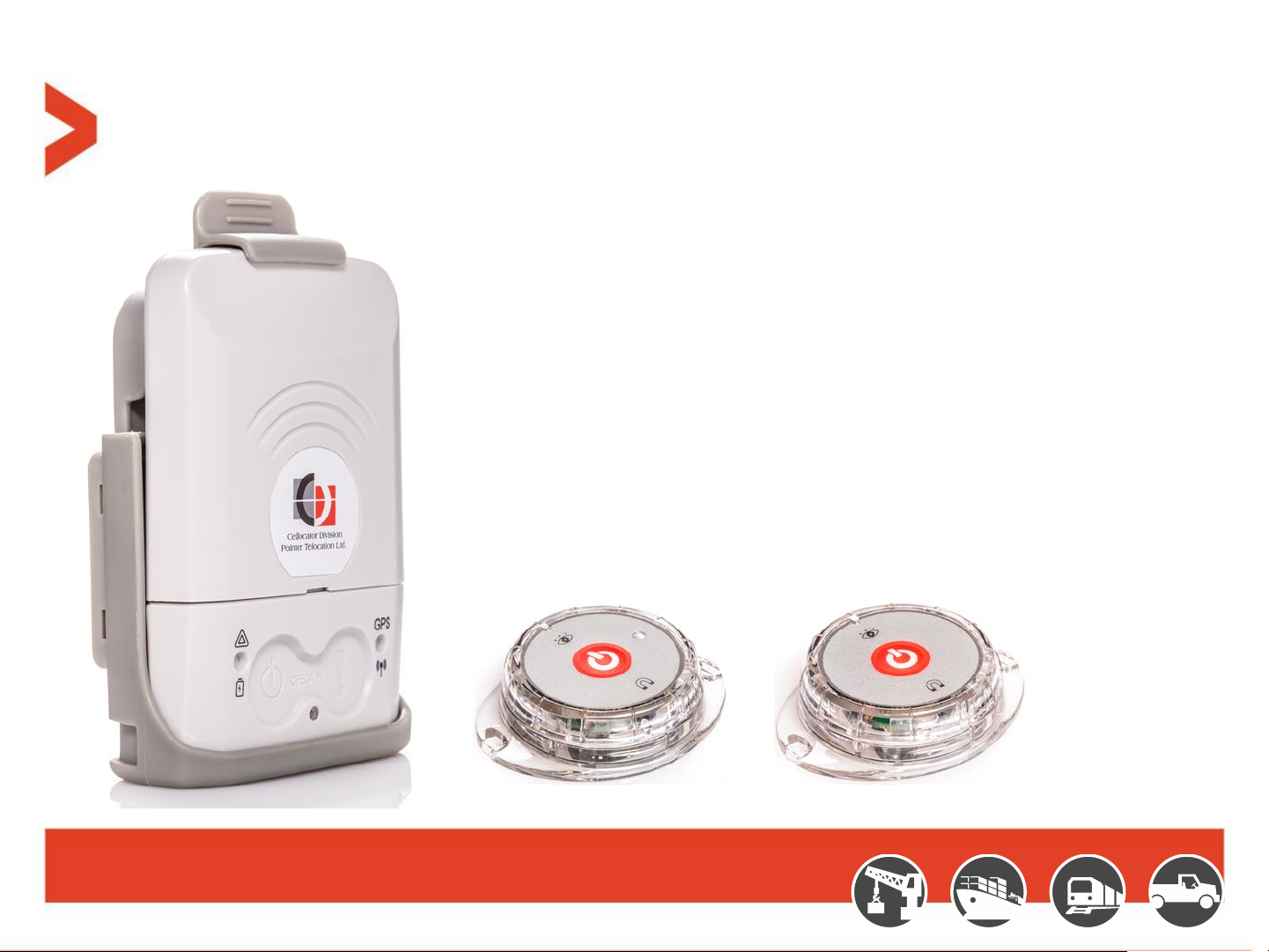
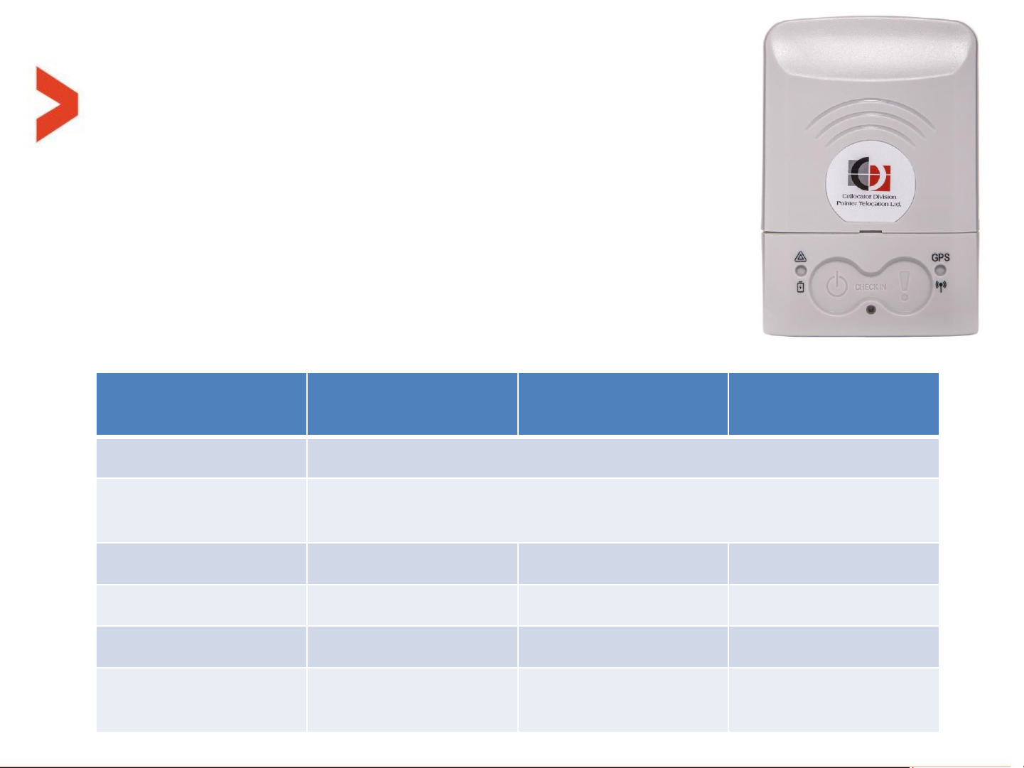
CelloTrack Nano
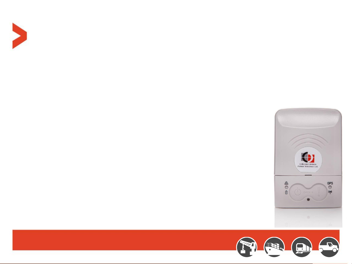
CelloTrack Nano™ Hub
Innovative, Smart and Compact asset monitoring device:
– SiRFstarV inside: multi GNSS (GPS, Glonass) with AGPS support (at 2
– Internal sensors: temperature, light, impact, movement, pressure, sound (microphone)
– Used as a hub for a Wireless Sensor Network via BLE interface
– 2G/3G communication to back-office application
– Advanced MMI: buzzer, status LEDs, multi-function buttons
– Low profile / compact and slick design (85x60x23mm, 94 gram)
– Dual Tampering detection
– Long life rechargeable Li-ion battery (up to 5 weeks of transport chain
usage)
– Micro USB connector for recharging the battery
– OTA update for Firmware and configuration
– IP 66 (dust and water jets), UV and chemicals protected
nd
phase)
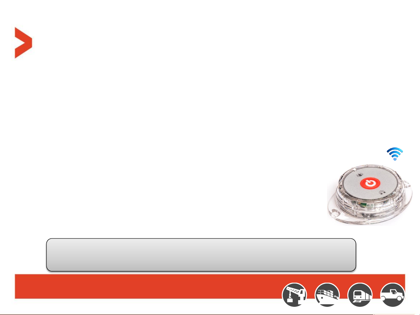
MultiSense Devices
A game changer in remote cargo & asset monitoring applications:
• Small, low cost device with rich embedded sensing capabilities:
– Temperature
– Humidity
– Movement
– Free Fall
– Impact
– Light
– Open/Close door/window
• BLE communication forms a cost effective Wireless Network with the Nano
• Long battery life for more than 1 year in common use case scenarios
• Easy battery replacement access (CR2450)
• Simple pairing with CelloTrack Nano
• On/Off Button
• LED indication for power on/off
• Small dimension (58.5 x 46 x 15mm, 26g including battery) and IP 67 enclosure
While paired with CelloTrack Nano, MultiSense provides a wireless sensing capability to a remote
location/facility where a wired interface is impractical. A Number of low cost MultiSense devices with
Nano GW dramatically reduces system’s TCO and improves monitoring efficiency

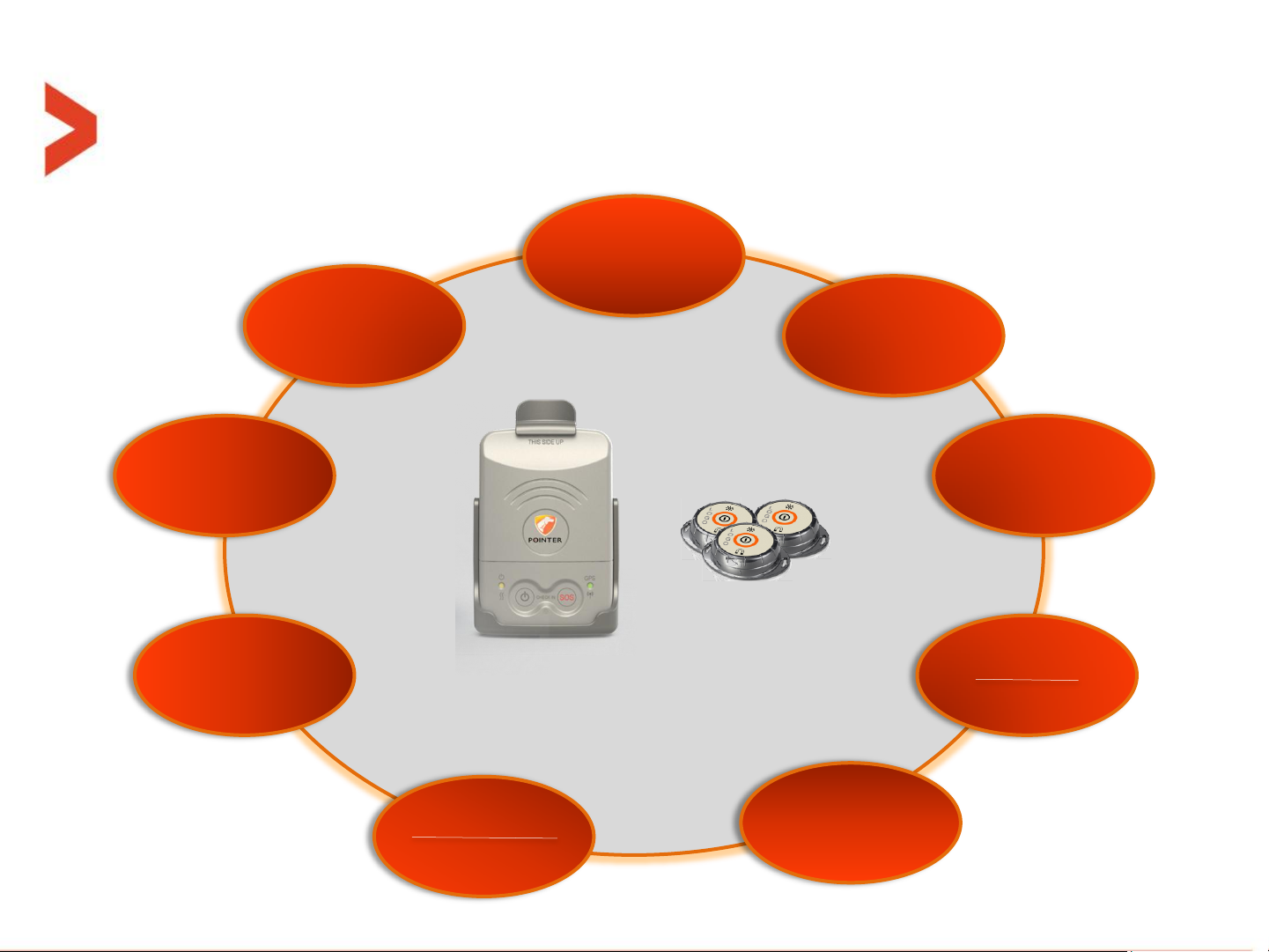
Solution Overview
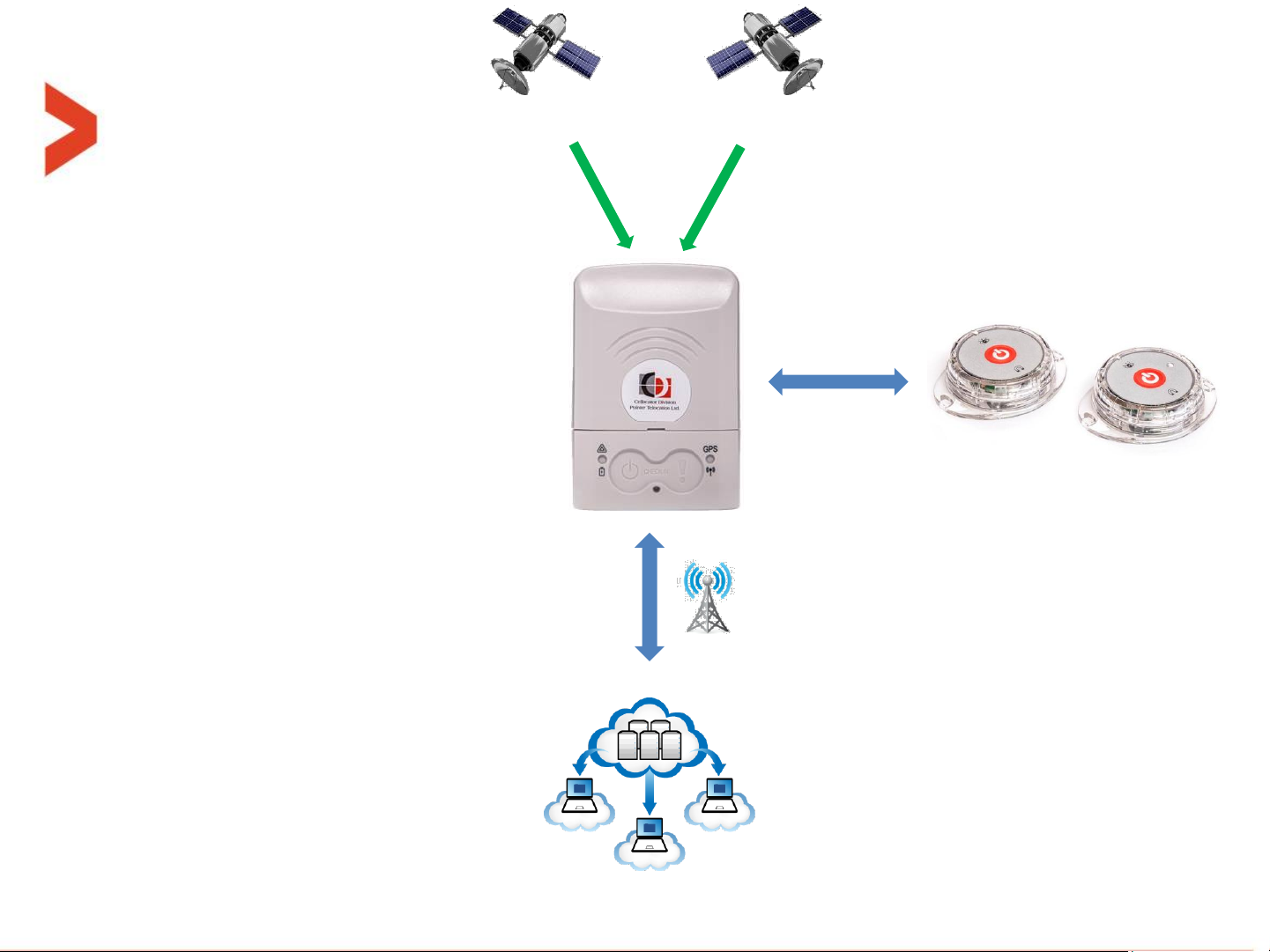
GPS
GLONASS
CelloTrack Nano
Smart Gateway
Up to 16 MultiSense
Location
SOS
Check In / Check out
Temperature
Free Fall
Barometric pressure
Impact
Light
Dual tamper
Multi-functional cradle
GSM
Remote Management
BLE
MultiSense
Temperature
Humidity
Free Fall
Impact
Light
Open/Close Door
Multi Sensors
Humidity
(MultiSense)
Temperature
Light
Barometric
Pressure
(Nano)
Geo Fencing
(Nano)
Tampering
Proximity
Open/Close
Door
(MultiSense)
Free Fall
Impact
Movement


System Operation

CelloTrack nano terminology
– Active state = ON state = Unit is turned ON
– Inactive state = OFF state = Unit is turned OFF (the lowest power consumption)
– “Indications time window” = the time window that the LEDs and buzzer are active. After
that time, they are shut down to save energy. This window opens after power up, reset
and pressing one of the buttons. This size of this window is configurable.
– “Check-in” = A feature that when both buttons are pressed the unit sends it location with
a check-in transmission reason.
– MultiSense pairing = When the operator wants the nano to be connected/linked/paired
with a certain MultiSense unit, the nano and the MultiSense must first perform a pairing
process, where the nano register the MultiSense MAC address in one place of its 16 cells
table.
– BIST = Build-In Self-Test process, preformed after reset or power-up (battery connection).
– “Guest mode” = When this mode is enabled in the nano, it will communicate with any
MultiSense in its range, forwarding its sensors data to the server.
User interface - Buttons
Pressing Duration
Left button
Right button
Both
simultaneously
T < 200mS
Ignored
T > 200mS
Very short feedback from buzzer,
Open the indications time window
1 Sec > T > 200mS
-
-
Check-in event
2 Sec > T > 1 Sec
-
Check-in event
5 Sec > T > 2 Sec
Panic event
Check-in event
T > 5 Sec
Power-off unit
Panic event
MultiSense pairing
window open
Buttons overview table while the unit is in
active state:
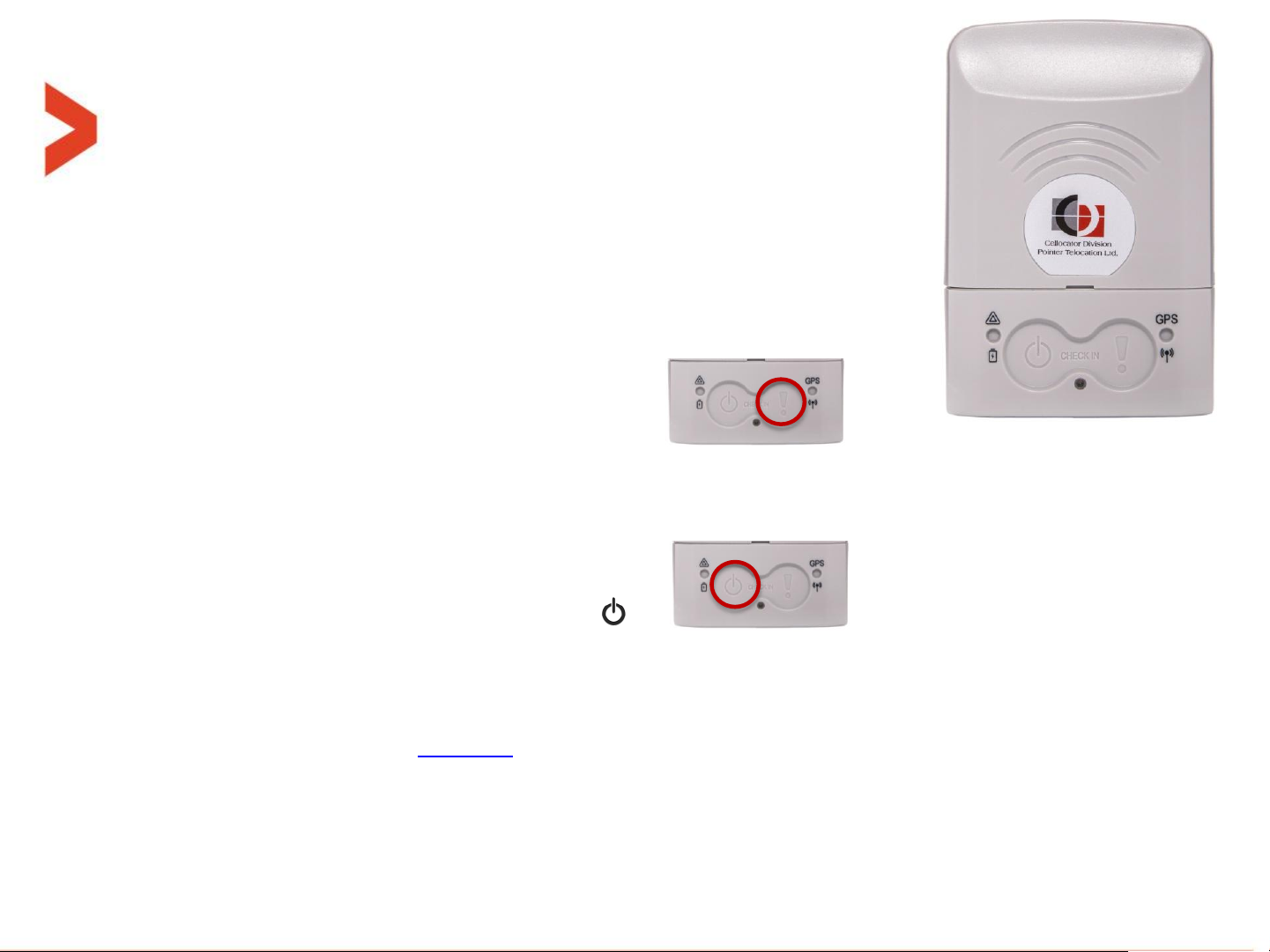
User interface - Buttons
Buttons:
– Every press on a button when the unit is active will get a short
audible beep feedback by the buzzer, if enabled at parameter
“Button press Buzzer feedback“.
– The Right button - Panic button (marked "!“):
Pressing for 2 seconds or more (even if not released), followed by engagement feedback
(configurable by Buzzer enable bits), A panic event will be sent to the server. ACK by the server
will generate another reception feedback - configurable by “Panic was ACKed by server Buzzer
feedback” bit.
– The Left button – Power button (marked “ “):
Short press (<5 seconds) will open the configurable size indication time window.
– Also, this button is turning the unit ON and OFF:
– Turning ON - pressing 3 seconds while turned OFF. After that the system shall go to self
test as described at this slide.
– Turning OFF - pressing 5 seconds while turned on.
– At the end of that period, the turning ON/OFF take place even if the button is not released.
User interface - Buttons
Check in feature:
– Pressing simultaneously on both buttons for at least 1 second
(and less than 5 seconds), followed by a 0.5 second buzzer beep
every elapsed second if enabled at the PL, and/or LEDs feedback (configurable at the PL),
and shall transmit the current location once.
– It is also related to set the baseline reference accelerometer position of the man down
feature detailed in the programming manual.
MultiSense pairing feature:
– Pressing simultaneously on both buttons for more than 5 second will initiate the
MultiSense in-field pairing process.
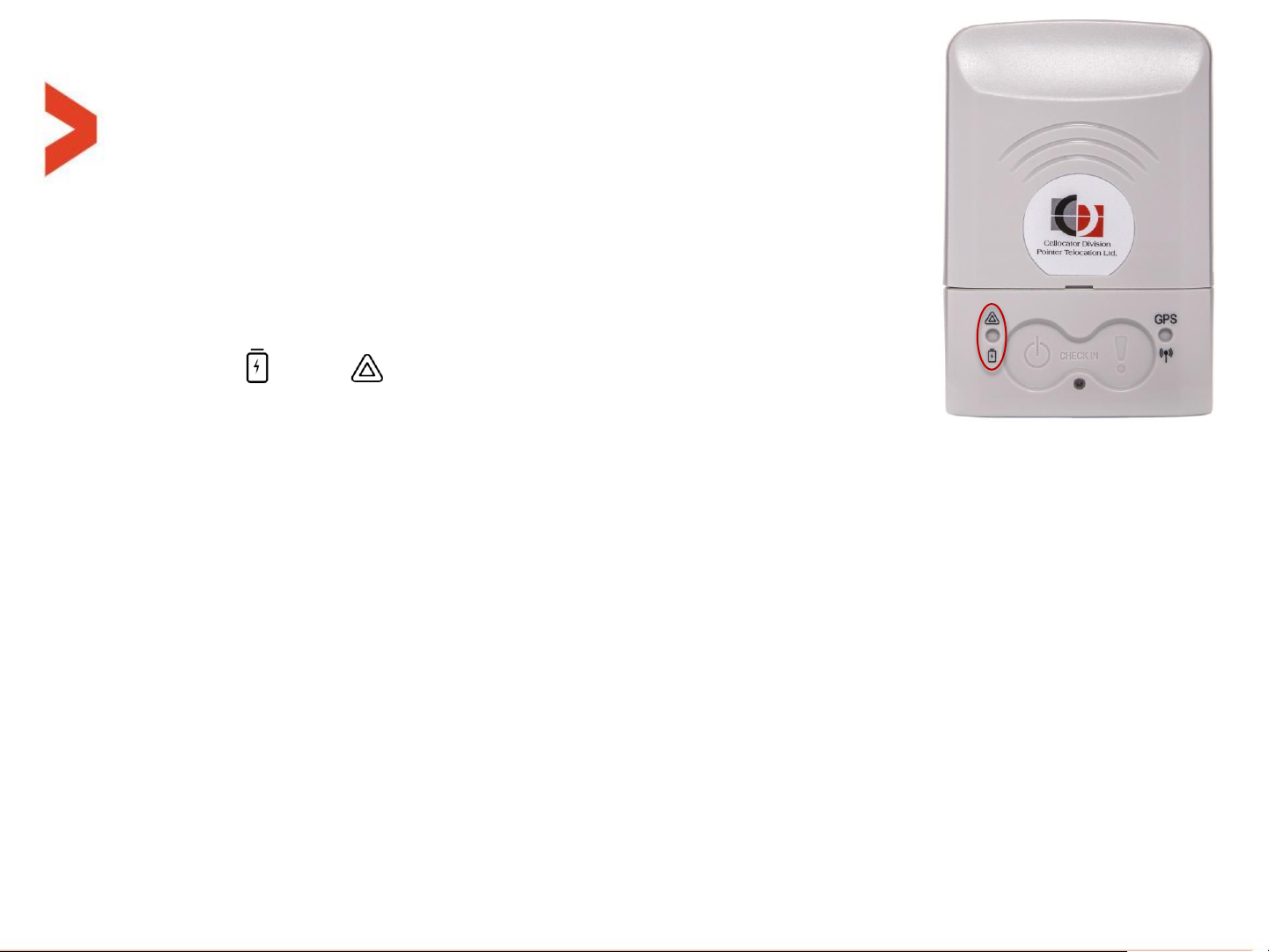
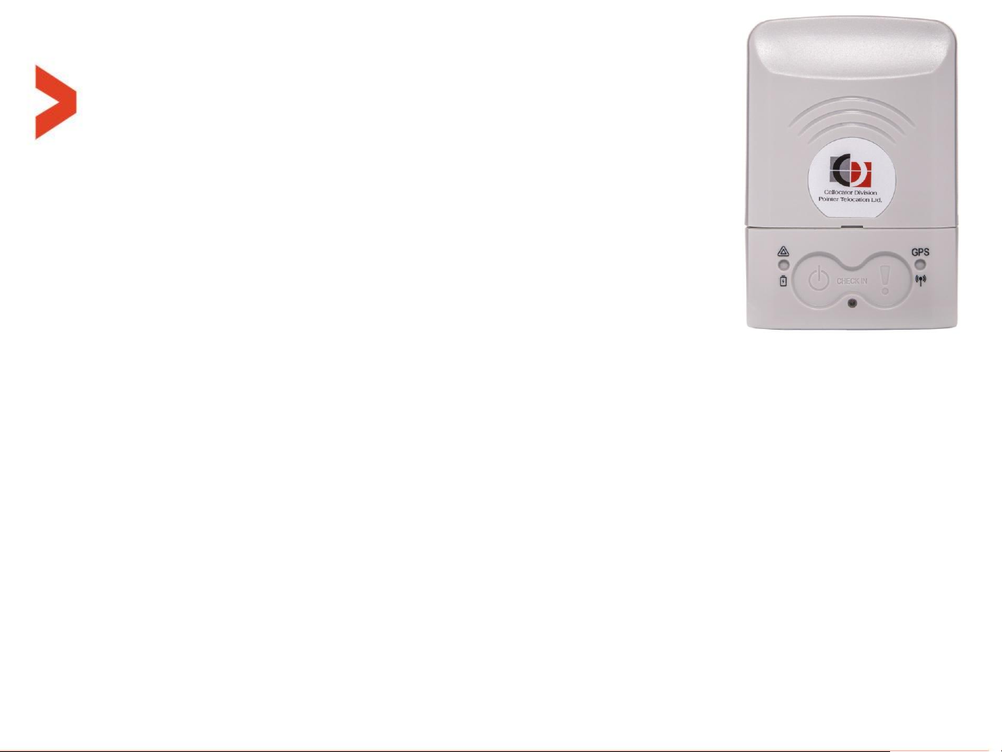
User interface - LEDs
Left LED – Battery and deviations:
– marked " " and " " gives indication on the power/battery and
deviations (as explained in next slide).
– When unit is turned ON, or a short press on left button (shorter than 5 seconds), or
following reset command, all the following LED indications are restarted according to
“nano indications time window”.
– Battery status: When unit is turned ON, short blink of 100mS every X seconds to show
battery status according to the following legend:
Battery is 50-100% - Green:
█__________________█__________________█__________________█_...
Battery is 20-49% -Orange:
█__________________█__________________█__________________█_...
Battery is 0-19% - Red:
█__________________█__________________█__________________█_...

User interface - LEDs
Out of range indications on Left LED:
– When unit is turned ON, or a short press (shorter than 5 seconds) on left button
is pressed, only the most severe indication from the following list is displayed
once if that violation/deviation still exists.
– When any sensor creates an out-of-range (alert) event, and if enabled by a
parameter in the PL, the left LED will signal a 3 seconds long continuous (once)
or non-continuous pulse according to the following color scheme:
Light sensor out of range: __████████████████___
Accelerometer out of range: __████████████████___
Temperature out of range: __████████████████___
Geo-fence violation: __█████_█████_█████___
– "Light sensor out of range" means: light level of the local sensor crossed the "open/close
package threshold" event.
– "Accelerometer out of range" means: orientation change event only.
– "Temperature out of range" means: local temperature sensor is either above the upper TH or
below the lower TH.
– "Geo-fence violation" means: all the possible violation kinds supported and defined in legacy.
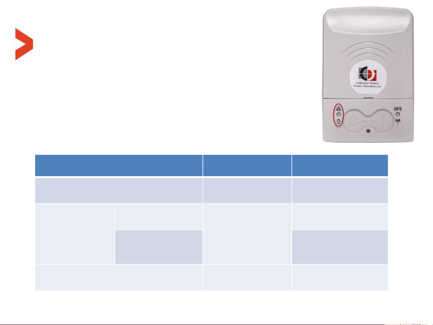
User interface - LEDs
Unit mode:
OFF (inactive)
ON (active)
During actual charging
Constantly
orange
Constantly
orange
After charge
completion
Inside the "Indications
time window"
Constantly
green
Regular LEDs
indications
After (outside) the
"Indications time
window"
Constantly
green
Battery Fault
Constantly red
Constantly red
Charging indications on Left LED:
– When micro-USB connector is plugged-in and charging is in fact
in progress, whether from charger (AC wall adaptor) or PC, the
left LED will act as described in the table below:
– These indications have the highest priority and they override all other indications on this LED
 Loading...