

Page 1

User Manual
Version V1.4 Oct. 2010
VariPOS™ / VariPPC™
© Copyright Poindus Systems 2010 P1 / 40
Page 2

© Copyright Poindus Systems 2010 P2 / 40
Copyright 2010
All Rights Reserved
Manual Version 1.4
The information contained in this document is subject to change without notice.
We make no warranty of any kind with regard to this material, including, but not limited to, the implied
warranties of merchantability and fitness for a particular purpose. We shall not be liable for errors
contained herein or for incidental or consequential damages in connection with the furnishing,
performance, or use of this material.
This document contains proprietary information that is protected by copyright. All rights are reserved. No
part of this document may be photocopied, reproduced or translated to another language without the
prior written consent of the manufacturer.
TRADEMARK
Poindus®/ VariPOS TM are registered trademarks of Poindus Systems.
Intel
®
/ PineView® are registered trademarks of Intel® Corporation. Microsoft® and Windows® are
registered trademarks of Microsoft Corporation.
Other trademarks mentioned herein are the property of their respective owners.
Page 3

Safety
IMPORTANT SAFETY INSTRUCTIONS
1. To disconnect the machine from the electrical power supply, turn off the power switch and remove
the power cord plug from the wall socket. The wall socket must be easily accessible and in close
proximity to the machine.
2. Read these instructions carefully. Save these instructions for future reference.
3. Follow all warnings and instructions marked on the pr oduct.
4. Do not use this product near water.
5. Do not place this product on an unstable cart, stand, or table. The product may fall, causing serious
damage to the product.
6. Slots and openings in the cabinet and the back or bottom are provided for ventilation to ensure
reliable operation of the product and to protect it from overheating. These openings must not be
blocked or covered. The openings should never be blocked by placing the product on a bed, sof a, rug,
or other similar surface. This product should nev er be placed near or o ver a r adiator or heat r egister
or in a built-in installation unless proper ventilation is provided.
7. This product should be operated from the type of power indicated on the marking label. If you are
not sure of the type of power available, consult y our dealer or local power company.
8. Do not allow anything to rest on the power cord. Do not locate this product where person s will walk
on the cord.
9. Never push objects of any kind into this product through cabinet slots as they may touch dangerous
voltage points or short out parts that could result in a fire or electric shock. Never spill liquid of any
kind on the product.
CE
This device complies with the requirements of the VariPOSTM directive 2004/108/EC with regard to
“Electromagnetic compatibility”.
FCC
This device complies with part 15 of the FCC rules. Operation is subject to the following two
conditions:
(1) This device may not cause harmful interference.
(2) This device must accept any interference received, including interference that may cause
undesired operation
CAUTION ON LITHIUM BATTERIES
There is a danger of explosion if the battery is replaced incorrectly. Replace only with the same or
equivalent type recommended by the manufacturer. Discard used batteries according to the
manufacturer’s instruction s.
© Copyright Poindus Systems 2010 P3 / 40
Page 4

© Copyright Poindus Systems 2010 P4 / 40
Table of Contents
1 Packing List 5
1-1 Standard items ...........................................................5
1-2 Accessory items..........................................................6
2 System Overview 7
2-1 I/O Interface...............................................................9
3 Specification 10
4 System Assembly & Disassembly 11
4-1 Open the System......................................................11
4-2 Replace the HDD......................................................13
4-3 Install a Customer Display........................................15
4-4 Install a Second Display............................................16
4-5 Install a Cash Drawer...............................................19
4-6 Install the MSR & iButton Reader.............................21
4-7 Install the Metal Stand .............................................22
4-8 Install the Wall Mount Kits........................................23
5 Jumper Settings 24
5-1 Motherboard Layout (D410 & D510 CPU).................24
6 Serial Port Pin 9 Mode Settings 27
7 Spare parts List 29
8 Appendix 38
Page 5
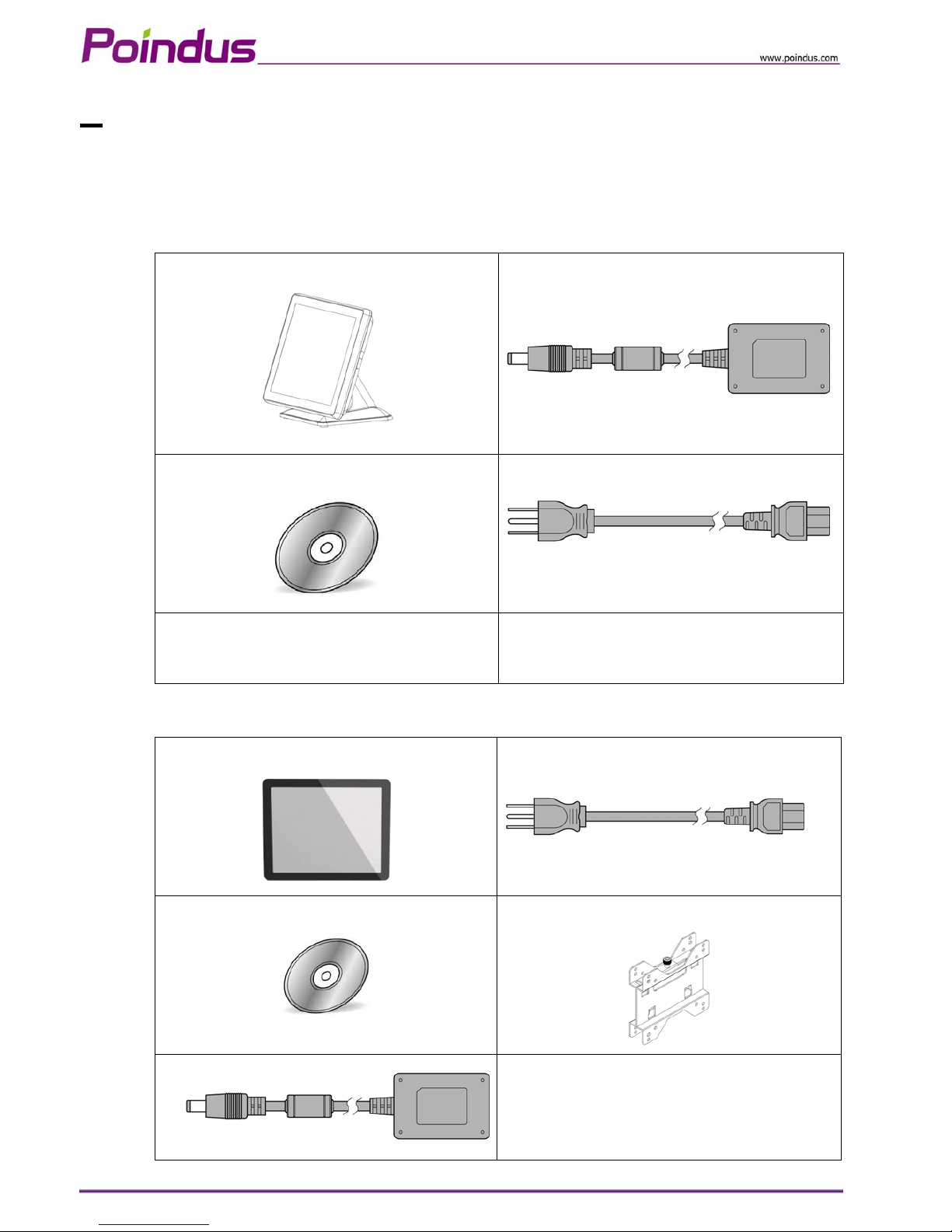
1 Packing List
1-1 Standard items
【 VariPOS 】
a.
c.
b.
d.
a. System
b. Driver bank CD
c. Power adapter
d. Power cord
【 VariPPCTM 】
a.
d.
b.
e.
c.
a. System
b. Driver bank CD
c. Power adapter
d. Power cord
e. Wall Mount Kit
© Copyright Poindus Systems 2010 P5 / 40
Page 6

© Copyright Poindus Systems 2010 P6 / 40
1-2 Accessory items
Part No Description Q’ty
1 3XCC00000010 Touch Screen Wipes ,20*15mm 1
2 3XPP00000010 SPIRAL WARPPING BANDS SWB-16,L15mm 1
*1 SCREW PACK: security screws 1 3 *7P0000000030
Screw driver 1
4 3CMD9M100100 RJ-45 Cable 1
5 3CW000000190 VGA Cable*2 1
*1: There are security screws and a screw driver for replacing the hard drive fixing screw. Customers can
use the security screws to ensure HDD security.
*2: VGA Cable is only for I/O interface with VGA port.
Page 7
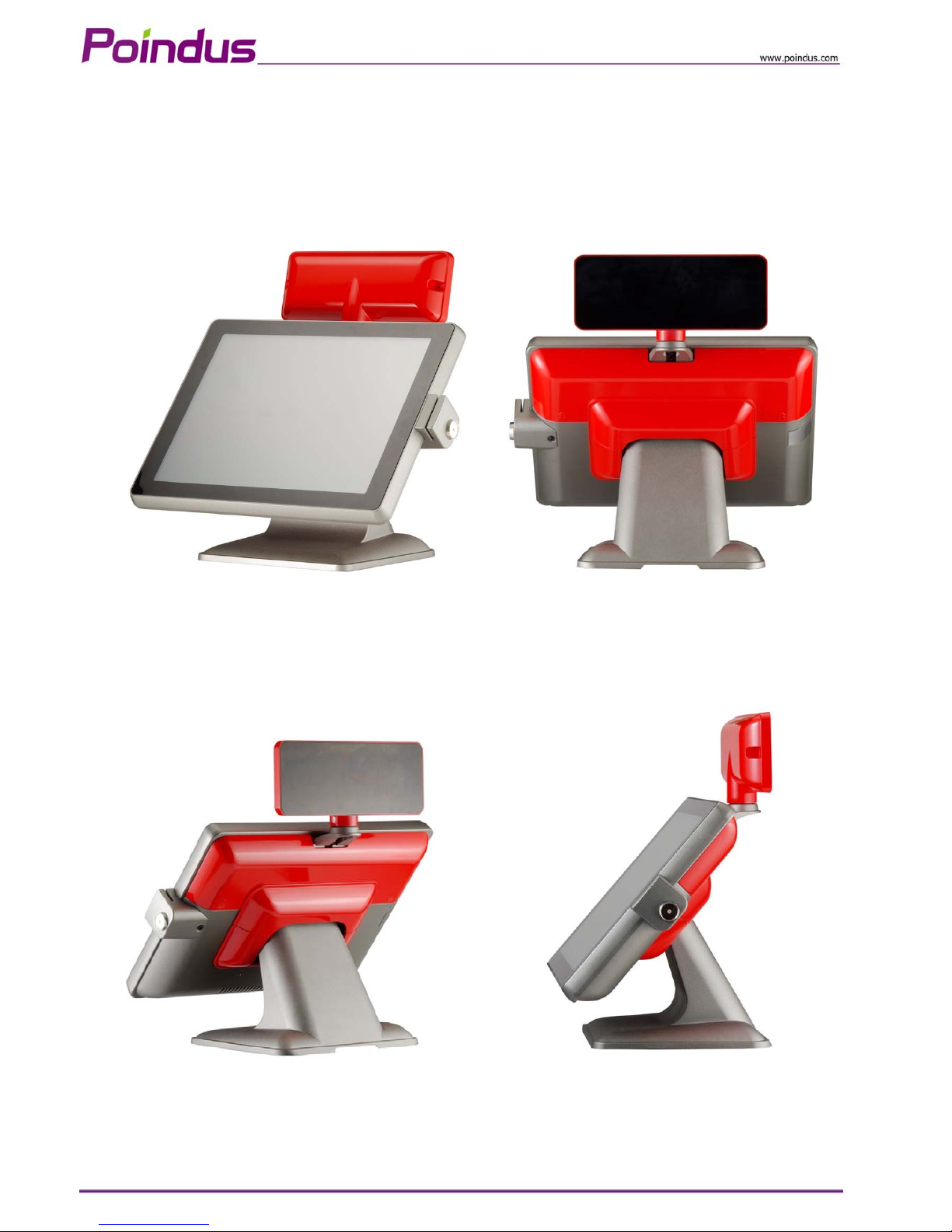
2 System Overview
【VariPOS™】
© Copyright Poindus Systems 2010 P7 / 40
Page 8
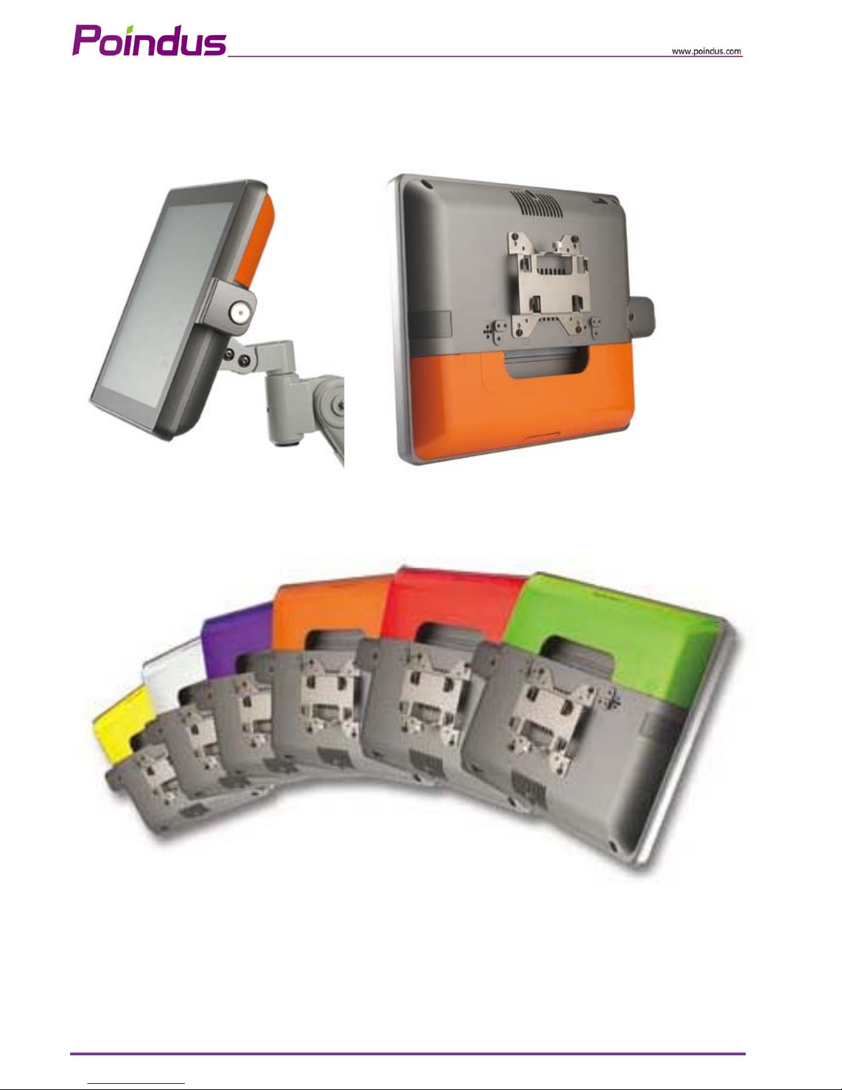
【VariPPC™】
© Copyright Poindus Systems 2010 P8 / 40
Page 9
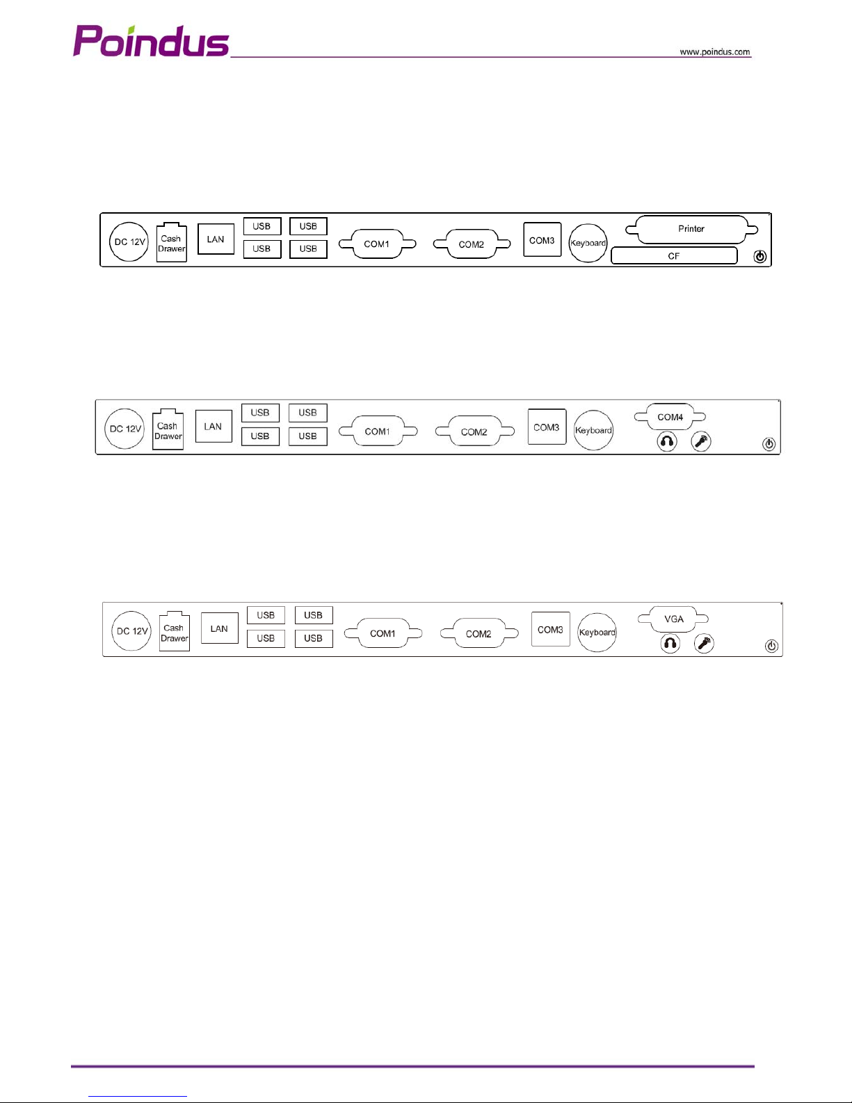
2-1 I/O Interface
【Standard Version】
【COM 4 Version】
【VGA Version】
© Copyright Poindus Systems 2010 P9 / 40
Page 10
© Copyright Poindus Systems 2010 P10 / 40
3 Specification
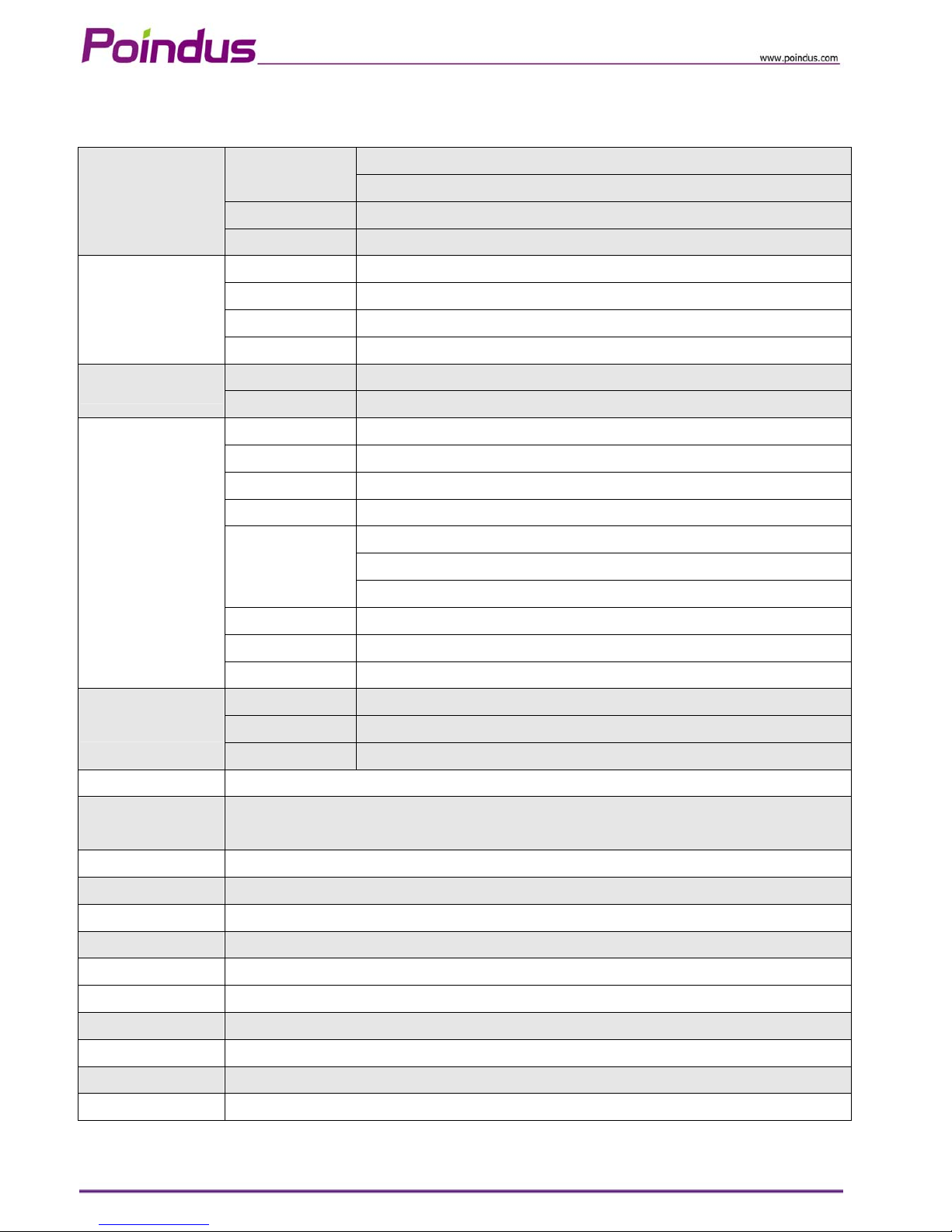
Intel® Pineview D410 (Single Core) 1.66GHz with L2 Cache 512KB
CPU
Intel® Pineview D510 (Dual Core) 1.66GHz with L2 Cache 1MB
Chipset Intel® Pineview + ICH8M
Main Board
System Memory 1 x SO-DIMM DDRII 667, up to 2GB
TFT LCD 38.1cm (15’’)
Brightness 250nits
Resolution 1024 x 768
Display
Touch Screen True Flat Projected Capacitive Technology / True Flat 5-Wire Resistive
HDD Type 1 x SATA 6.4cm (2.5”) HDD
Storage
Compact Flash Type 1 x Slot Type II (Standard)
DC Input 1 x Mini Din 4P (DC 12V only)
Cash Drawer 1 x RJ-11 (Power Pin 12V)
Network (LAN) 1 x Gigabit Ethernet by RJ-45
USB Port 4 x USB 2.0
4 x RS-232 COM1/2 : DB-9, RS-232, Pin9 w/RI/5V/12V Selectable by BIOS
COM3 : RJ-48 for VFD, RS-232, Pin10 w/RI/5V/12V Selectable by BIOS
Serial Port
COM4 : DB-9, RS-232, Pin9 w/RI/5V/12V Selectable by BIOS (optional)
PS/2 Port 1 x PS/2 connector for Ke yb oard
LPT Port 1 x DB-25 Printer Port (Standard)
I/O Ports -External
VGA Port 1 x DB-15 VGA Port (optional)
Card Reader & iButton COM5 : Internal Pin header for Card Reader & iButton
Audio AC 97 2.0 compliant, 2W Speaker x 2
I/O Ports -Internal
Bus Expansion 1 x Mini-PCI-E Slot
Compliance IP 66 on front panel
System Management
Desktop Management Interface (DMI) / Preboot Execu tio n Env iron m ent (PXE) / Wake on LAN (Wo L) / Advanced
Configuration and Power Interface (ACPI)
OS Support Windows 7, Windows POSReady 2009, WEPOS, Windows XP Pro for Embedded, Fedora(Linux)
Power Supply External adapter, DC Model:80 Watts, Voltage:+12VDC 6.6 max
Material Main Unit: Die-casting aluminum ; I/O Cover: Plasti c
Color Main Unit: Grey *Customized color for plastic parts
Certifications CE, FCC, Class-A, RoHS, WEEE
Dimensions ( W x H x D ) 370 x 287 x 55mm
Weight 4.7 Kg (Aluminum Base: 1.3 Kg )
VESA Mounting 100 x 100mm
Operating Temperature
0℃ ~ 40℃, 10% ~ 90% RH, non-condensing
Storage Temperature
-20℃ ~ 60℃, 10% ~ 90% RH, non-condensing
*Poindus reserves the right to change the spe cification without prior notice.
Page 11
4 System Assembly & Disassembly
4-1 Open the System
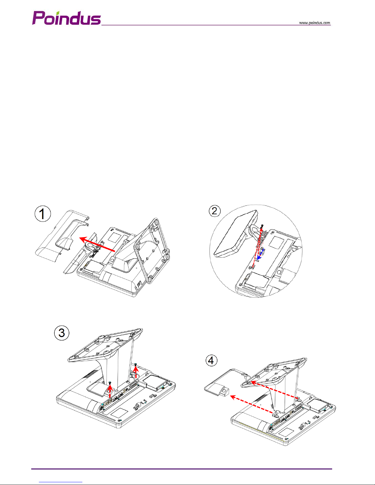
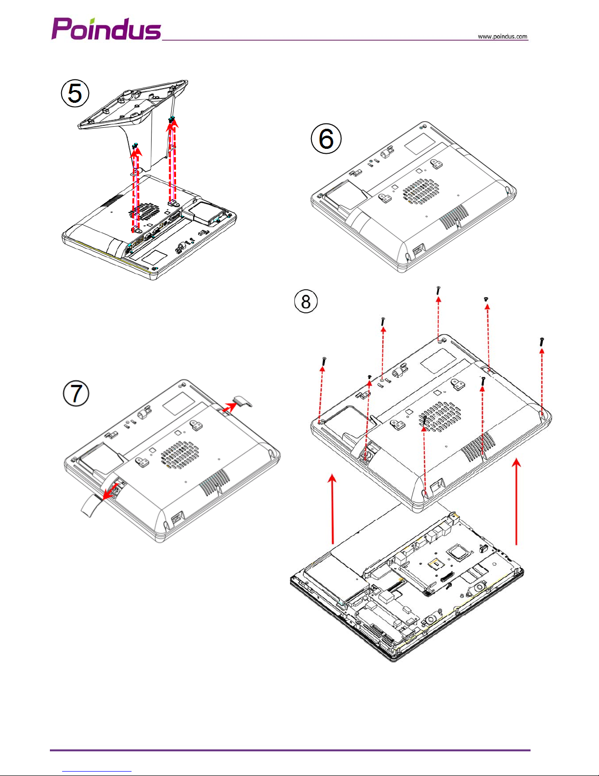
To access the inside system, you need to open the system first and the procedure of opening the
system is as below:
1. Open the back IO cover
2. Release the screws of VFD
3. Release the screws of hinge cover
4. Remove the plastic hinge cover parts
5. Release the screws of base
6. Open the plastic cover from two sides
7. Release the screws of aluminium back frame
© Copyright Poindus Systems 2010 P11 / 40
Page 12
© Copyright Poindus Systems 2010 P12 / 40
Page 13
4-2 Replace the HDD
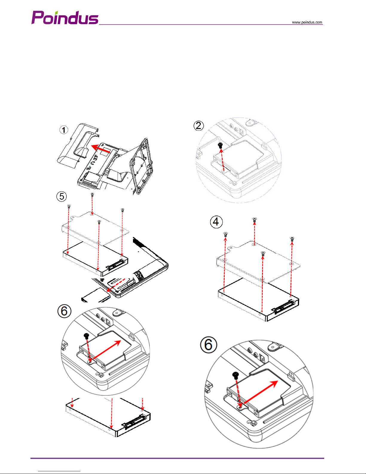
1. Open the IO back cover
2. Release the 1x screw from HDD tray
3. Remove the HDD tray.
4. Release the 4 x round screws on the HDD tray and replace HDD
5. Screw 4 x round screws on the HDD tray and insert the HDD tray into the whole system HDD slot
6. Fix HDD tray on the system with the 1x screw
© Copyright Poindus Systems 2010 P13 / 40
Page 14
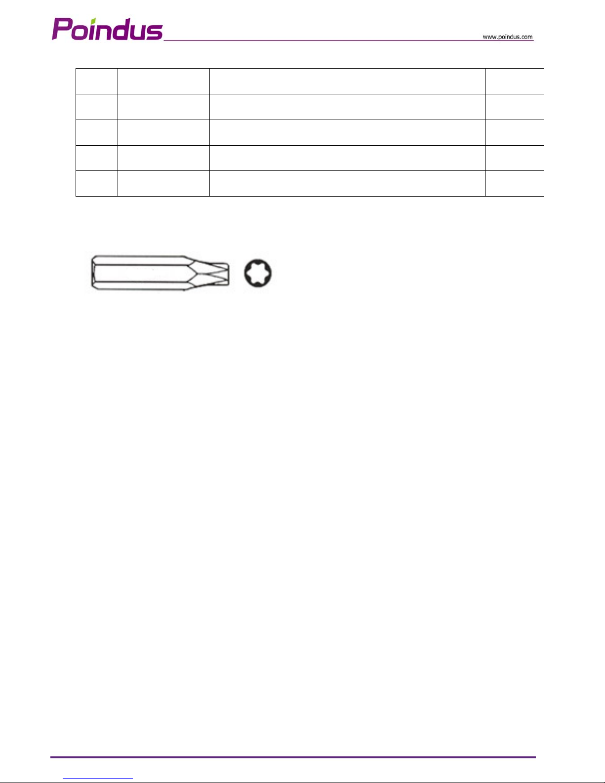
Screw Pack
Item Part No. Description Q’ty
A 3SMFH30040N0 F-HEAD SCREW:M3*0.5-4mm,NI 5
B 3SMPH30062N0 P-HEAD SCREW:M3*0.5-6mm,NI(FLOWER) 2
C 3SLFR03651B0 Screwdriver(FLOWER) 1
D 3SMUH30061N0 ROUND WASHER HEAD SCREWS:m3*0.5-6MM,NI 3
Security Screws*
* There are security screws and a screw driver enclosed in product carton.
* Customers can use the special security screws to ensure HDD security.
© Copyright Poindus Systems 2010 P14 / 40
Page 15
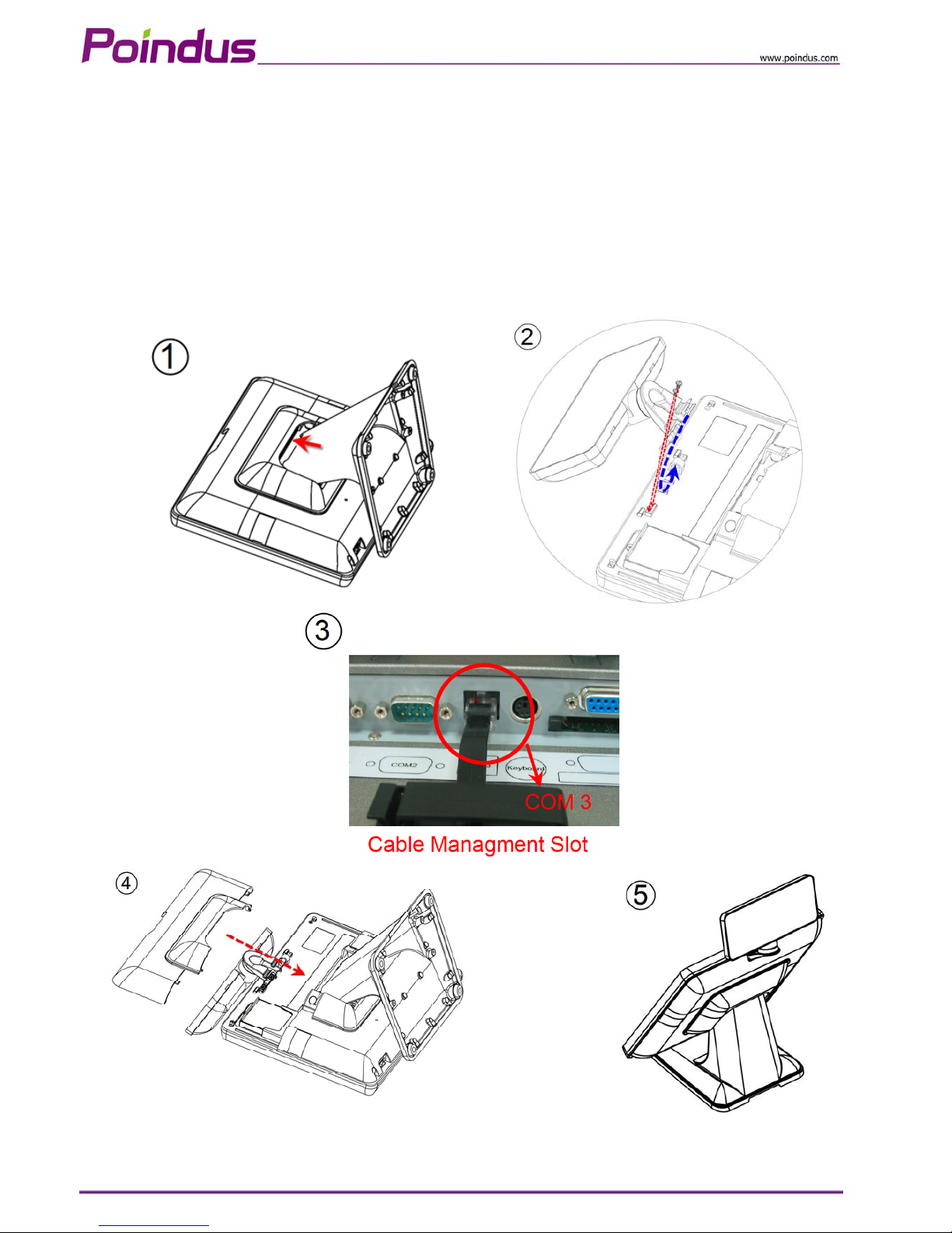
4-3 Install a Customer Display
1. Put the panel on the flat table & open the IO back cover of system.
2. Assemble the customer display hinge into the customer display slot and fasten 2 x screws.
3. Connect the customer display into COM3 via the cable management slot and adjust COM3 v oltage to +12V
in BIOS (refer to Chapter 6)
4. Fasten the IO cover into the right position and turn the system on the right position.
© Copyright Poindus Systems 2010 P15 / 40
Page 16
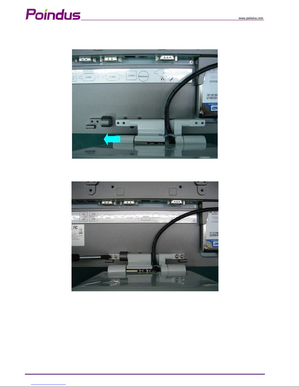
4-4 Install a Second Display
1. Slide the 2nd display hinge into the hinge holder on VariPOS.
2. Tighten the 4 screws that attached in the accessory box.
© Copyright Poindus Systems 2010 P16 / 40
Page 17
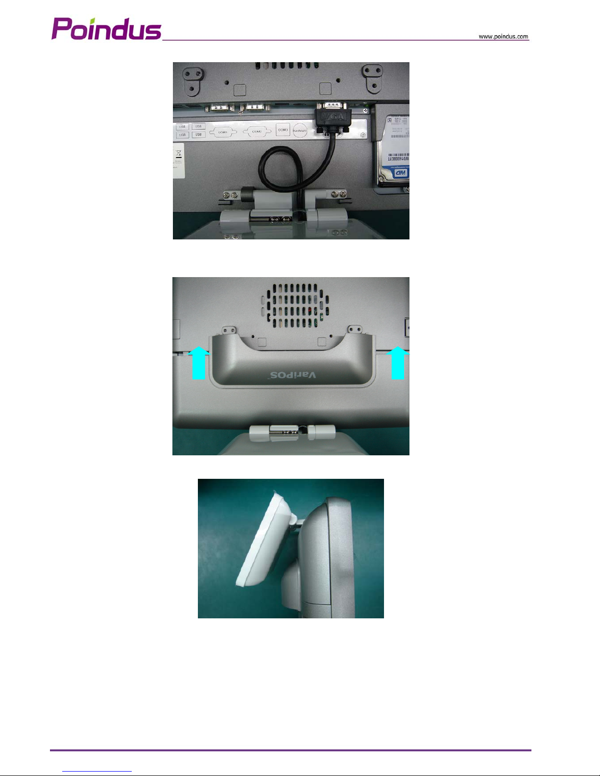
3. Plug the VGA cable to VGA port on the terminal.
4. Don’t forget to insert the I/O cover.
5. Done
© Copyright Poindus Systems 2010 P17 / 40
Page 18
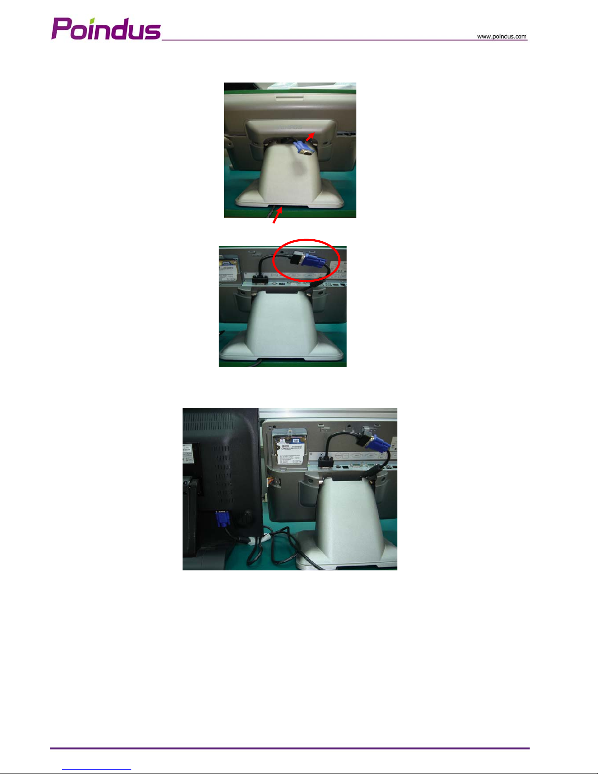
Installation for external monitor
1. Put the VGA cable of the external monitor through the base.
2. Connect the extension VGA cable enclosed with the accessory box to the VGA cable of the external monitor.
3. Plug the extension VGA cable to VGA port and install the I/O cover back to finish the installation.
© Copyright Poindus Systems 2010 P18 / 40
Page 19
4-5 Install a Cash Drawer
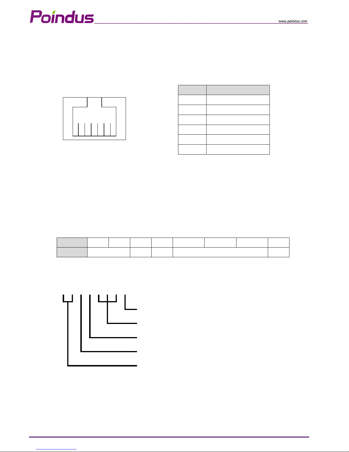
You can instal l a cash drawer through the cash drawer port. Please verify the pin assignment before
installation.
Cash Drawer Pin Assignment
© Copyright Poindus Systems 2010 P19 / 40
6 1
Pin Signal
1 GND
2 DOUT bit0
3 DIN bit0
4 12V
5 DOUT bit1
6 GND
Cash Drawer Controller Register
The Cash Drawer Controller use one I/O addresses to control the Cash Drawer.
Register Location: A22h
Attribute: Read / Write
Size: 8bit
BIT BIT7 BIT6 BIT5 BIT4 BIT3 BIT2 BIT1 BIT0
Attribute Reserved Write Write Reserved Read
7 6 5 4 3 2 1 0
X X X X X
Cash Drawer “DIN bit0” pin input status
Reserved
Cash Drawer “DOUT bit0” pin output control
Cash Drawer “DOUT bit1” pin output control
Reserved
Page 20
© Copyright Poindus Systems 2010 P20 / 40
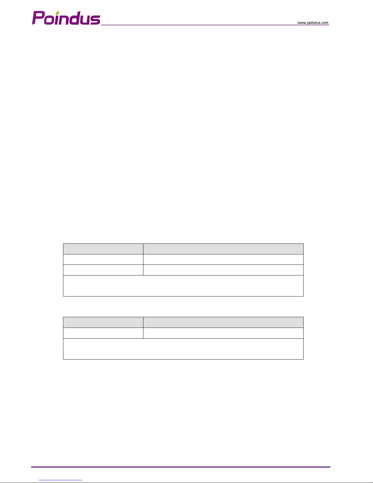
Bit 0: Cash Drawer “DIN bit0” pin input status.
= 1: the Cash Drawer closed or no Cash Drawer
= 0: the Cash Drawer opened
Bit 1: Reserved
Bit 2: Reserved
Bit 3: Reserved
Bit 4: Cash Drawer “DOUT bit0” pin output control.
= 1: Opening the Cash Drawer
= 0: Allow close the Cash Drawer
Bit 5: Cash Drawer “DOUT bit1” pin output control.
= 1: Opening the Cash Drawer
= 0: Allow close the Cash Drawer
Bit 6: Reserved
Bit 7: Reserved
Note: Please follow the Cash Drawer control signal design to control the Cash Drawer.
Cash Drawer Control Command Example
Use Debug.EXE program under DOS
Command Cash Drawer
O A22 10 Opening
O A22 00 Allow to close
¾ Set the I/O address A22h bit4 =1 for opening Cash Drawer by “DOUT bit0” pin control.
¾ Set the I/O address A22h bit4 = 0 for allow close Cash Drawer.
Command Cash Drawer
I A22 Check status
¾ The I/O address A22h bit0 =0 mean the Cash Drawer is opened or not exist.
¾ The I/O address A22h bit0 =1 mean the Cash Drawer is closed.
Page 21
© Copyright Poindus Systems 2010 P21 / 40
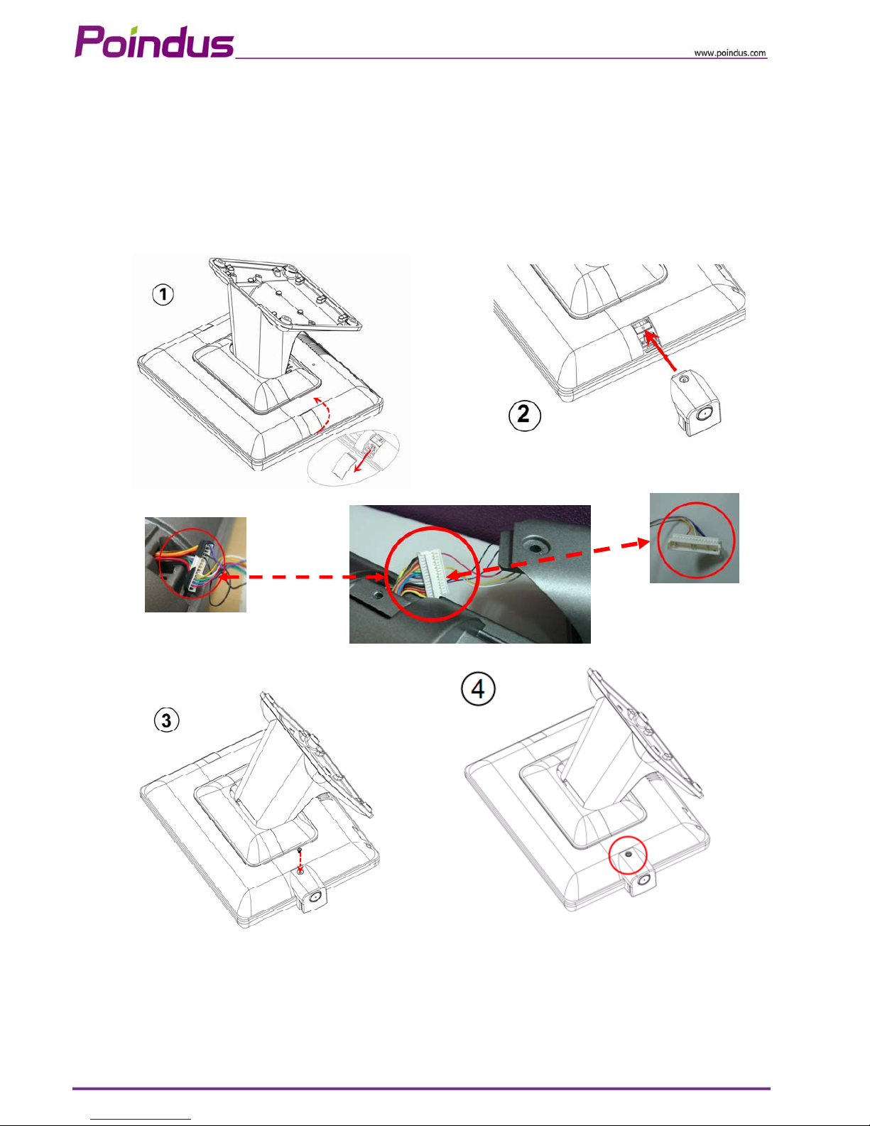
System connector supports PS/2
and RS-232 interface
MSR: RS-232 Interface
4-6 Install the MSR & iButton Reader
1. Open the right side cover of system. * MSR connection is supported on the right side
2. Connect MSR to System connector, system connector supports PS/2 and RS-232 interface.
3. Fasten the MSR screw on system
Page 22
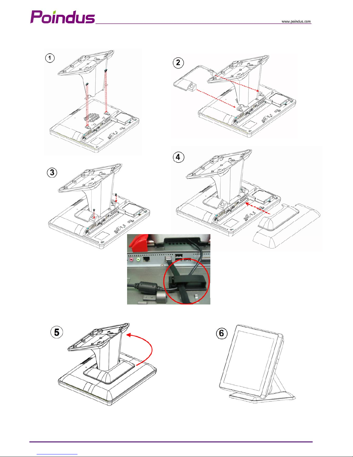
4-7 Install the Metal Stand
Power & VFD Cable Management
© Copyright Poindus Systems 2010 P22 / 40
Page 23
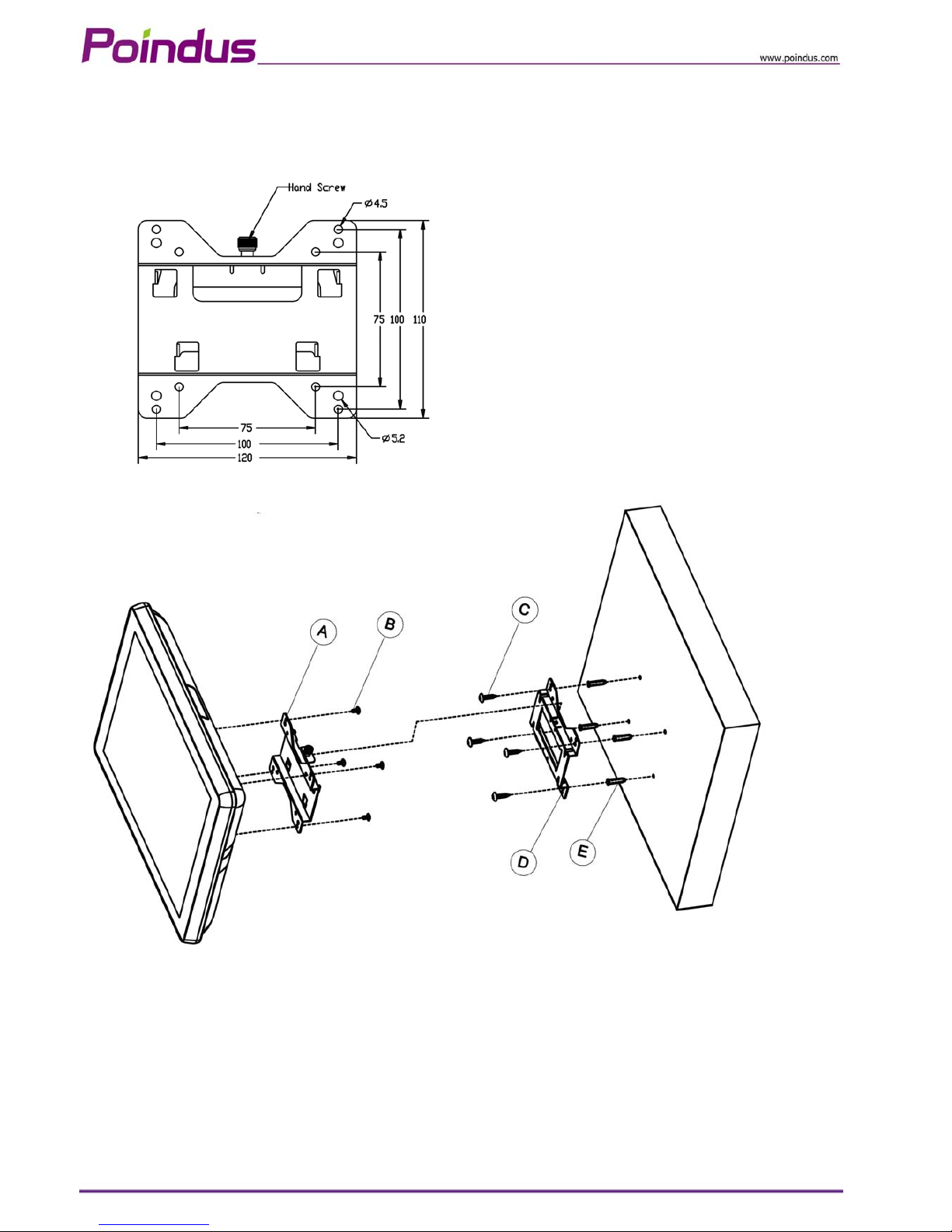
4-8 Install the Wall Mount Kits
© Copyright Poindus Systems 2010 P23 / 40
Page 24
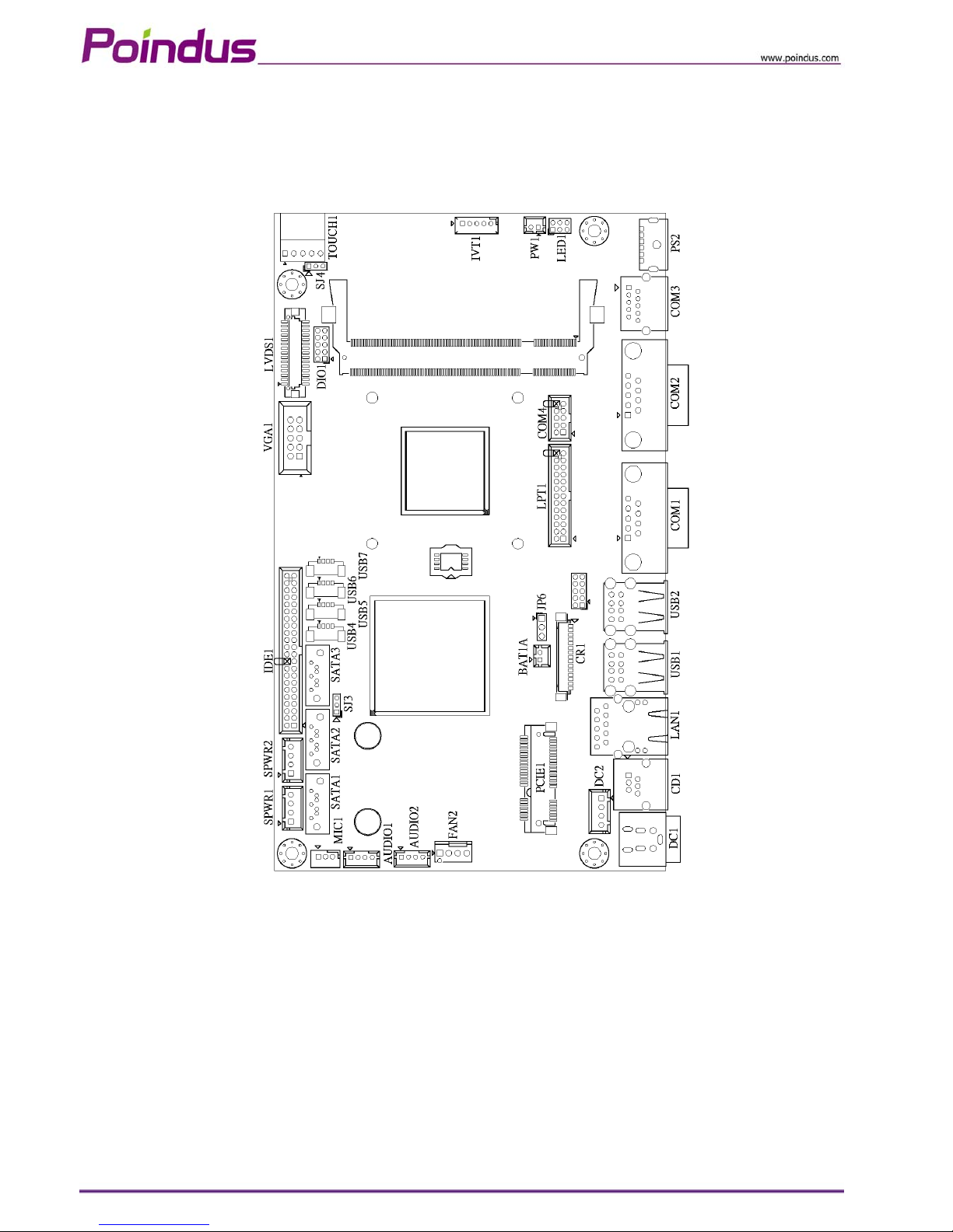
5 Jumper Settings
5-1 Motherboard Layout (D410 & D510 CPU)
© Copyright Poindus Systems 2010 P24 / 40
Page 25
© Copyright Poindus Systems 2010 P25 / 40
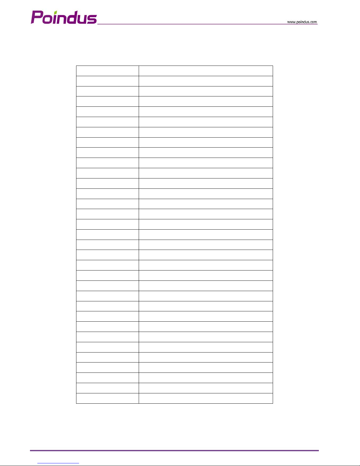
Connector & Jumper Setting
DC1 Mini Din 4P for Power Input Port
DC2 Internal Power Input Connector
CD1
RJ11 for Cash Drawer Port
LAN1 RJ45 for LAN Port
USB1, 2 USB dual stack for USB Port
USB4, 5, 6, 7 USB Connector
COM1 D-SUB 9 Pin for COM1 Port
COM2 D-SUB 9 Pin for COM2 Port
COM3 RJ48 for COM3 Port
COM4 COM4 Connector
PS2 PS/2 for Keyboard Port
SATA1 SATA 7 Pin for SATA1 Connector
SATA2 SATA 7 Pin for SATA2 Connector
SATA3 SATA 7 Pin for SATA3 Connector
SPWR1, 2 Power Output for SATA HDD
IDE1 PATA Connector
LVDS1 LCD Connector
VGA1 VGA Connector
CR1 Card Reader Connector
AUDIO1 Speaker out Connector
AUDIO2 Line out Connector
MIC1 MIC in Connector
LPT1 Printer Connector
TOUCH1 5W Resistive Touch Connector
PCIE1 Mini PCI -E Socket
PW1 Power Button Connector
IVT1 Inverter Connector
FAN2 CPU Fan Connector
LED1 LED Connector
BAT1A CMOS Battery Connector
DIO1 Digital Input / Output Connector
JP6 Clear CMOS
SJ3 SATA Power Enable for SATA3
Page 26
© Copyright Poindus Systems 2010 P26 / 40
JP6 : Clear CMOS Setup
JP6 Description
1-2 Normal operation
2-3 Clear CMOS
SJ3 : SATA Power Enable for SATA3
SJ3 Description
1-2 5V SATA Power Enable
2-3 Normal operation
● SJ3 setting SATA3 pin7 is GND or 5V.
Page 27
6 Serial Port Pin 9 Mode Settings
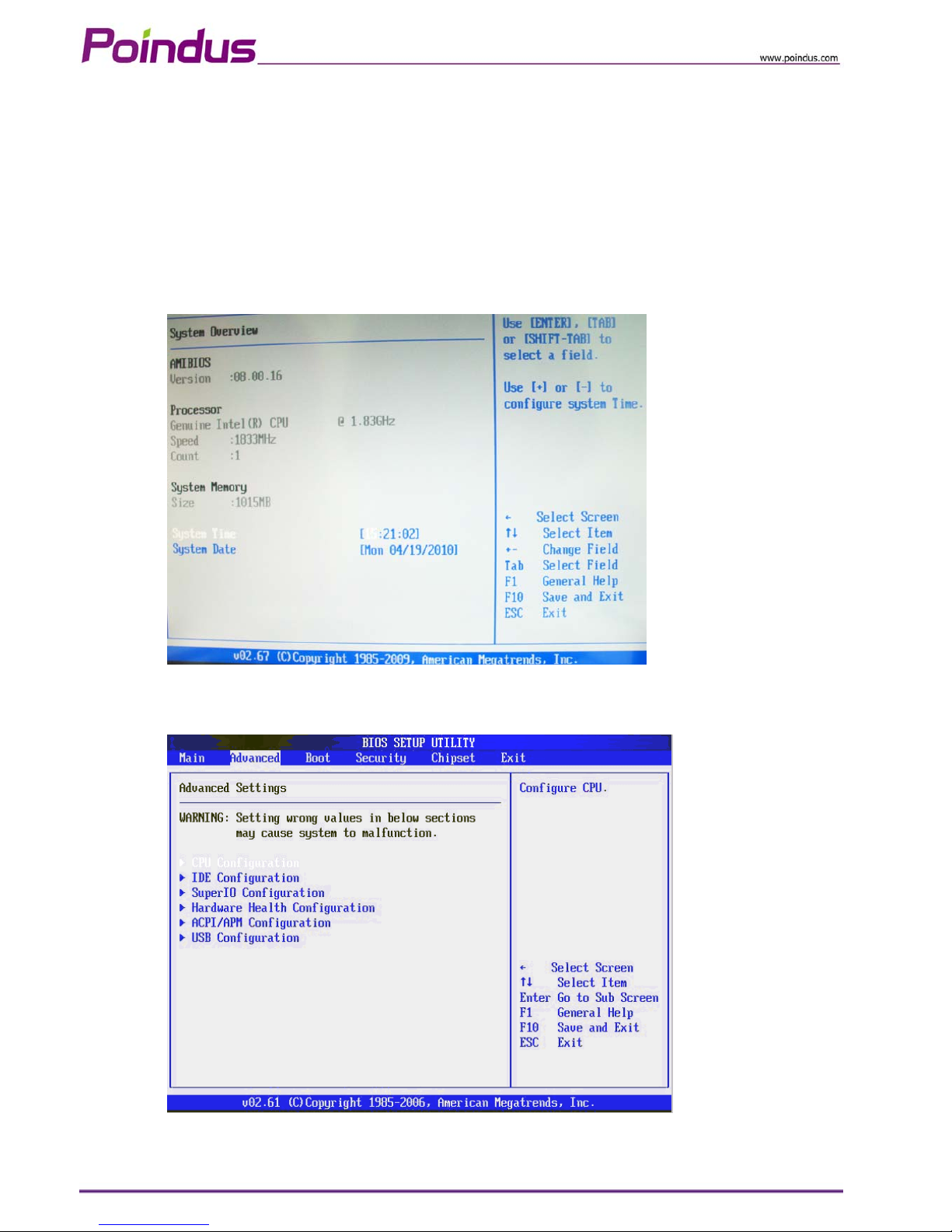
BIOS Main Menu
When the BIOS Main Menu is displayed, the following items can be selected. Use the arrow keys to select
items and the enter key to accept and enter the sub-menu.
Enter System Overview
Advanced Settings
Use this menu for set up super IO configuration.
© Copyright Poindus Systems 2010 P27 / 40
Page 28
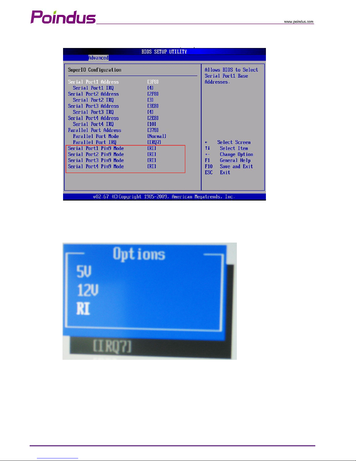
Select Super IO Configuration
Serial Port 1-4 Pin9 Mode
Enter into serial port 1- 4 Pin9 Mode and set up the options.
Select the serial port 1 Pin9 mode.
Save and Exit
© Copyright Poindus Systems 2010 P28 / 40
Page 29
7 Spare parts List
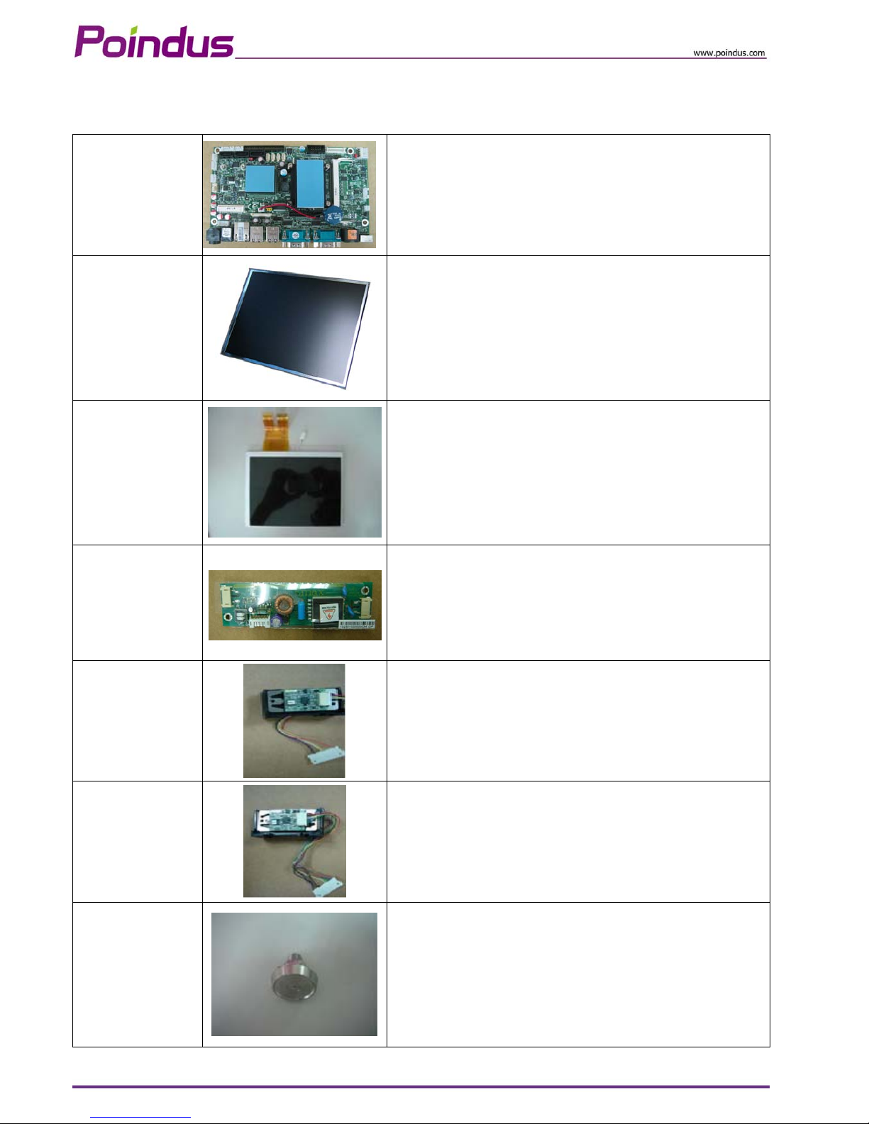
X
MBD51000010 SPARE PARTS: MAIN BOARD: PE01, PIN EVIEW D510 V1.0
6PN115052110
LCD PANEL: AUO , 15" TFT, 1024x768
6PN117001710 LED PANEL FOR 2ND DISPLAY
61V205510400
INVERTER:DUAL LAMP 5.5mA PLCD1715204BE
6CR000000010
MSR Module RS232
6CR000000020
MSR Module PS2
6CR842000000 I-BUTTON READER MODULE
© Copyright Poindus Systems 2010 P29 / 40
Page 30
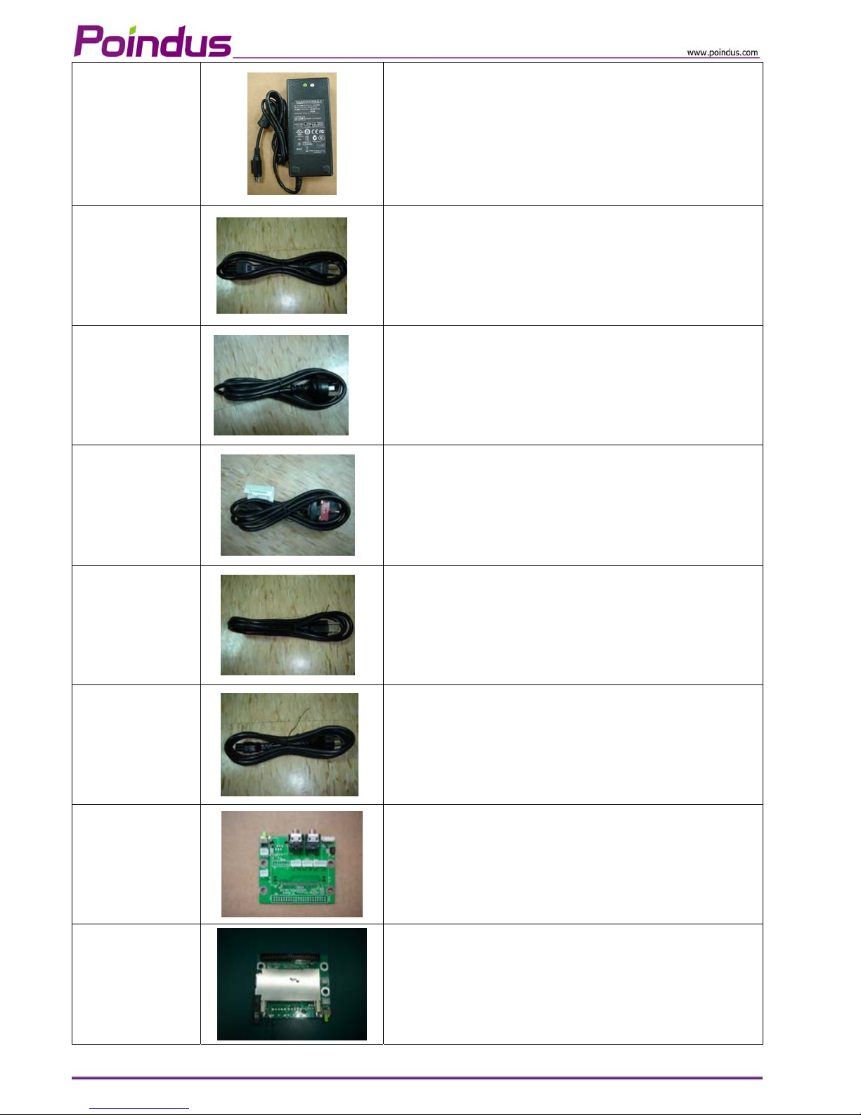
6PWA0804C000
POWER ADAPTER: DC12V/6.6A (EA11003C)
3CP000000050
POWER CORD (Brazil) TO MINI 3P
3CP000000040
POWER CORD (AU) TO MINI 3P
3CP000000030
POWER CORD (UK) TO MINI 3P
3CP000000010
POWER CORD (USA) TO MINI 3P
3CP000000020
POWER CORD (EU) TO MINI 3P
52FAUDV10010
A
UDIO BOARD FOR PE01 V1.0
52F0CFV10000
CF BOARD FOR PE01 V.10
© Copyright Poindus Systems 2010 P30 / 40
Page 31
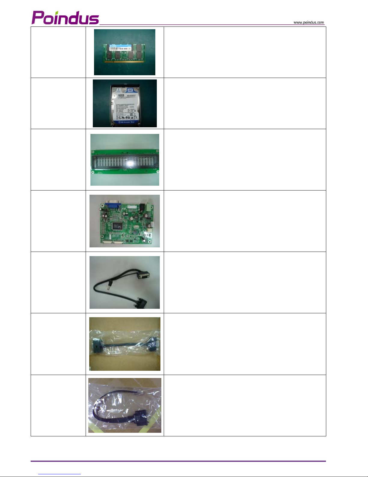
6RM000000010
RAM: SO-DIMM 2G DDRII 667MHz 200P
720000000010
HDD 160G ASSY,PP01
52FVFDV1000A
V
FD BOARD: PE02 V1.0
52ADB0000010
A
D BOARD FOR 2ND DISPLAY
3CW000000180
V
GA+POWER CABLE FOR 2ND DISPLAY
3CW000000190
Extend VGA cable
3CMD9MJT0100 COM3 CABLE RJ45/DB9
© Copyright Poindus Systems 2010 P31 / 40
Page 32
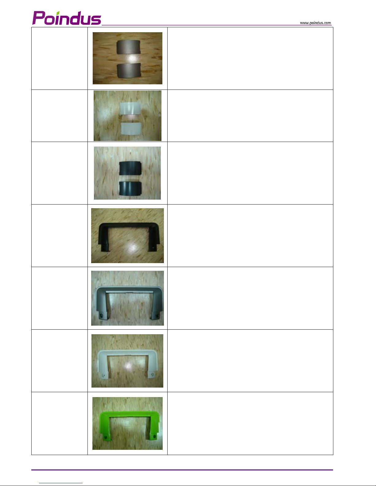
3P00040B0600
LCD SIDE COVER: Gray
3P00040E0400
LCD SIDE COVER: White
3P00040B0200
LCD SIDE COVER: Black
3P00050D0200
HINGE COVER: Black
3P00050D0600
HINGE COVER: Gray
3P00050F0400
HINGE COVER: White
3P00050D1000
HINGE COVER: Green
© Copyright Poindus Systems 2010 P32 / 40
Page 33
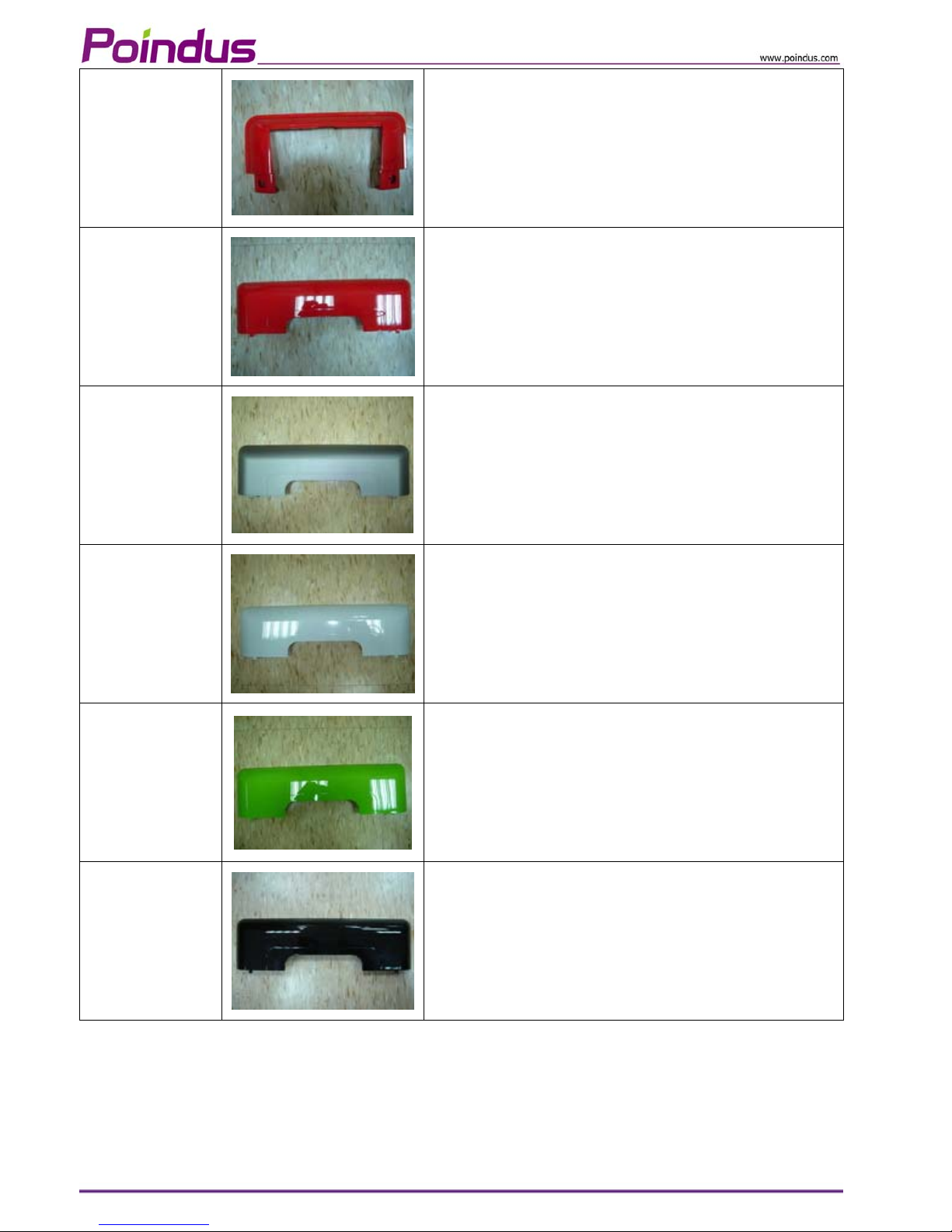
3P00050D0800
HINGE COVER: Red
3P00032D0800
PPC I/O cover: Red
3P00032D0600
PPC I/O cover: Gray
3P00032F0400
PPC I/O cover: White
3P00032D1000
PPC I/O cover: Green
3P0003D0200
PPC I/O cover: Black
© Copyright Poindus Systems 2010 P33 / 40
Page 34
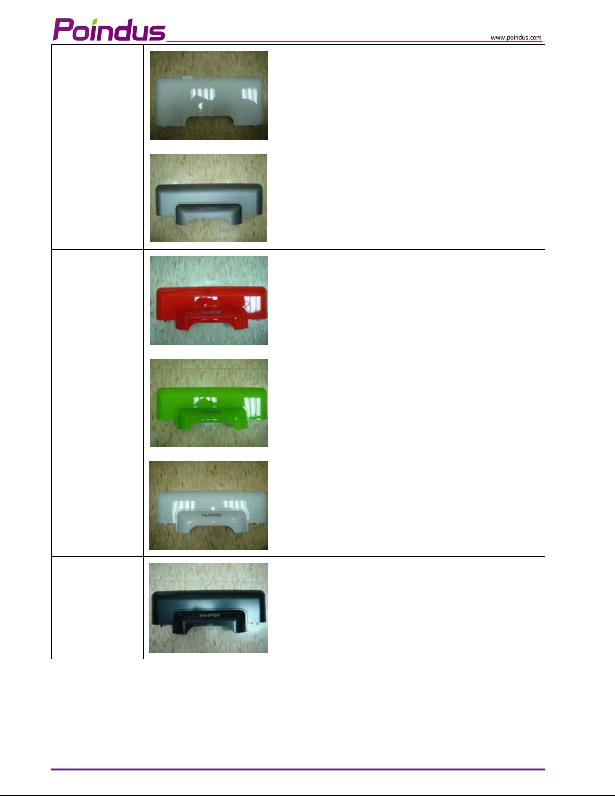
3P00120F0400
V
ariCura I/O cover: White
3P00030D0610
POS I/O cover w/o VFD: Gray
3P00030D0810
POS I/O cover w/o VFD: Red
3P00030D1010
POS I/O cover w/o VFD: Green
3P00030F0410
POS I/O cover w/o VFD: White
3P00030D0210
POS I/O cover w/o VFD: Black
© Copyright Poindus Systems 2010 P34 / 40
Page 35
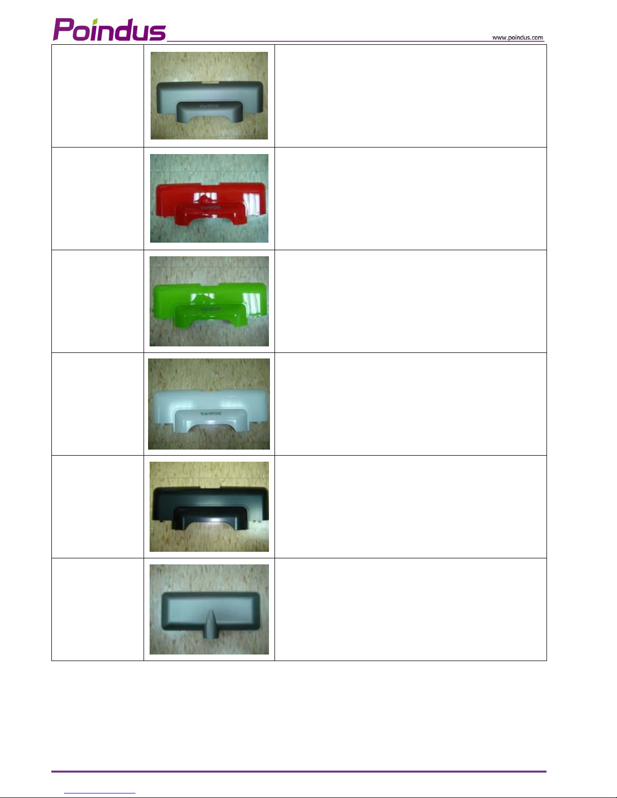
3P00031D0610
POS I/O cover W/VFD: Gray
3P00031D0810
POS I/O cover W/VFD: Red
3P00031D1010
POS I/O cover W/VFD: Green
3P00031F0410
POS I/O cover W/VFD: White
3P00031D0210
POS I/O cover W/VFD: Black
3P00060D0600
V
FD cover: Gray
© Copyright Poindus Systems 2010 P35 / 40
Page 36
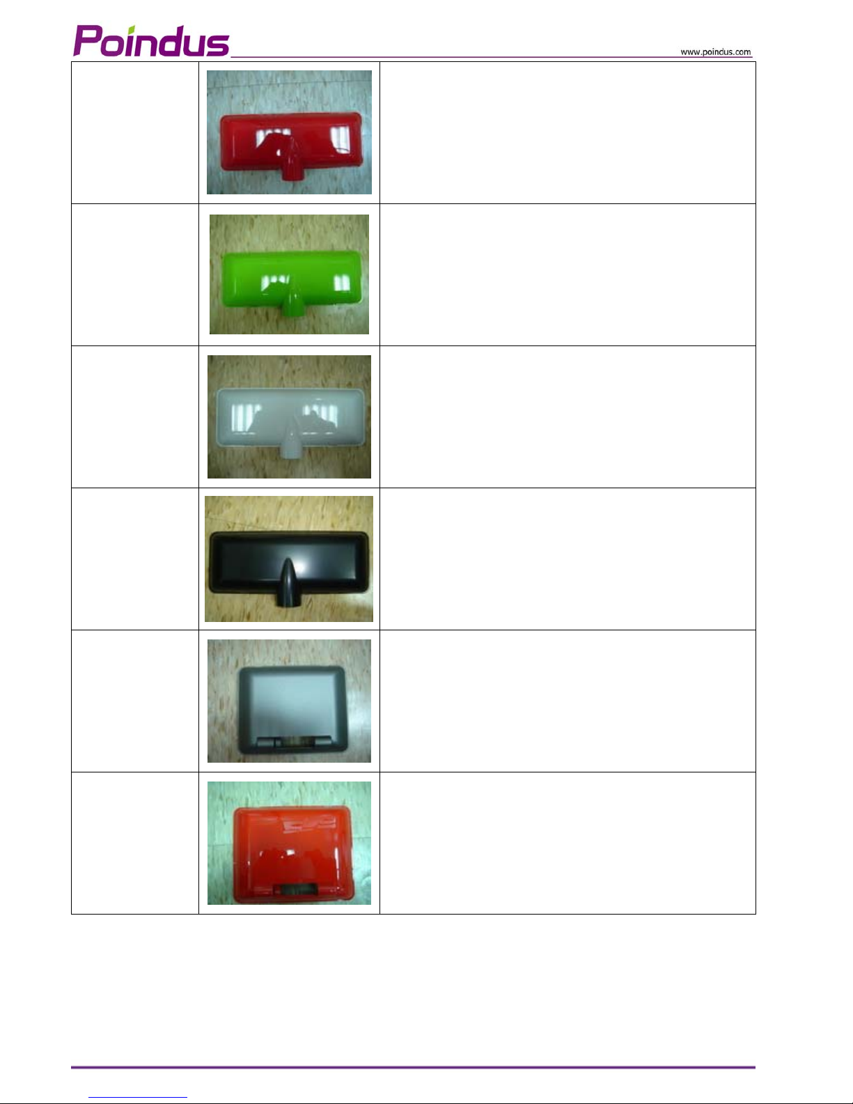
3P00060D0800
V
FD cover: Red
3P00060D1000
V
FD cover: Green
3P00060F0400
V
FD cover: White
3P00060D0200
V
FD cover: Black
3P00090D0600
2nd display rear cover: Gray
3P00090D0800
2nd display rear cover: Red
© Copyright Poindus Systems 2010 P36 / 40
Page 37
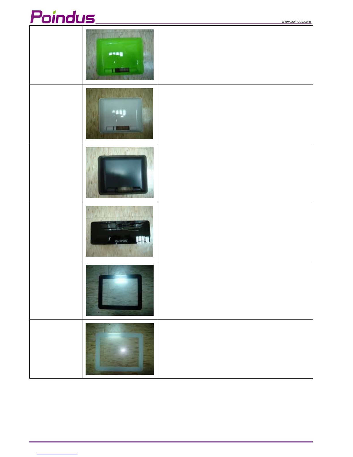
3P00090D1000
2nd display rear cover: Green
3P00090F0400
2nd display rear cover: White
3P00090D0200
2nd display rear cover: Black
3P00070P0910
V
FD LENS
3P00110K0200
2nd display LENS: Black
3P00110K0400
2nd display LENS: White
© Copyright Poindus Systems 2010 P37 / 40
Page 38
8 Appendix
Drivers Installation:
The shipping package includes a Driver CD. Y ou can find every individual driver and utility that enables you to
install the drivers in the Driver CD.
Please insert the Driver CD into the drive and double click on the “autorun.exe” to pick up the models.
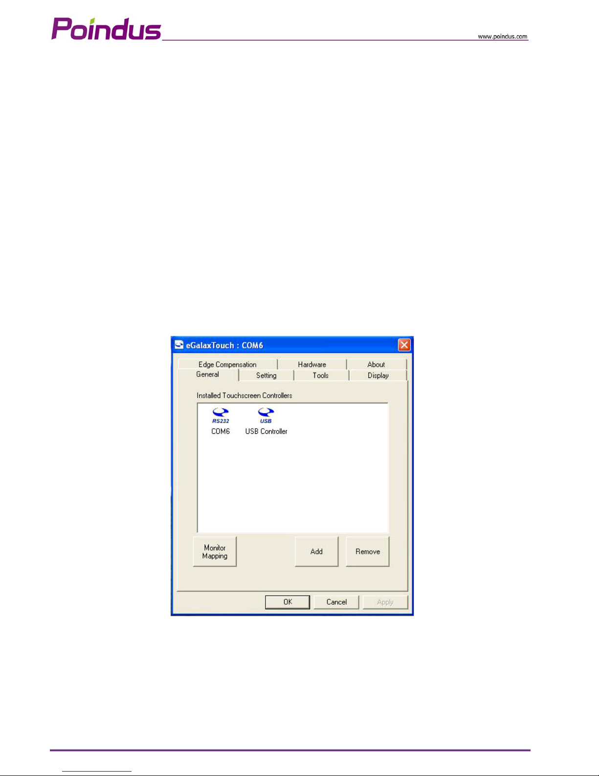
Notice:
1. If you use the Resistive touch panel, it is only showed COM6 installation finish image.
2. If you use the PCT touch panel, it will show the below image, please remove COM6 icon.
3. At the Windows 7 Operation System environment, when customer want to use PCT touch multi-touch it is
not required to install the touch driver.
4. Resistive touch is RS232 interface (COM6) and the PCT touch is USB interface.
© Copyright Poindus Systems 2010 P38 / 40
Page 39
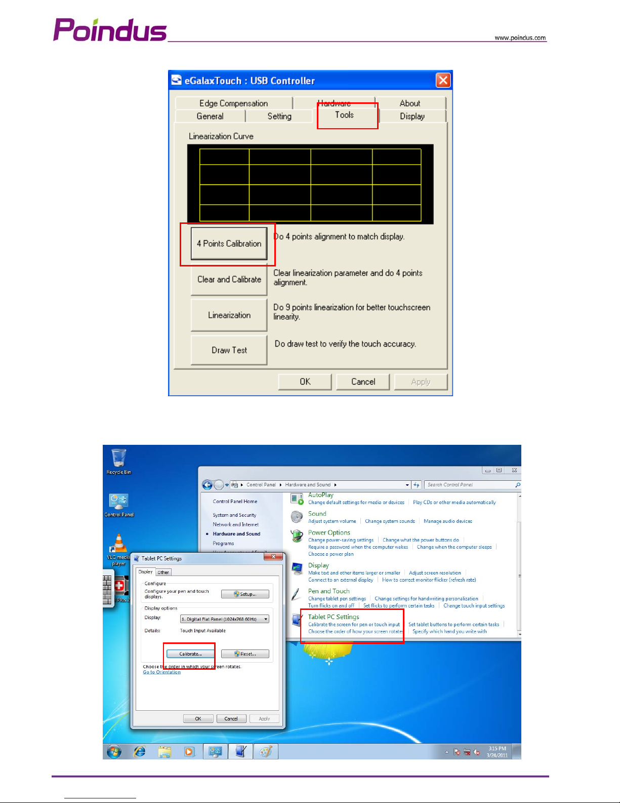
5. Calibration with EETI touch utility: please into “tool” page and press “4 Points Calibration”.
6. Calibration in WIN7: Control panelÆ Hardware and SoundÆTablet PC settingÆCalibrate the screen from
pen or touch input
© Copyright Poindus Systems 2010 P39 / 40
Page 40

© Copyright Poindus Systems 2010 P40 / 40
Version Change History:
Version Change Date Change Content
V1.0 May, 2010 1st Release
V1.1 June, 2010 Change the base installation steps
V1.2 August, 2010 Change the Jumper Setting
V1.3 September, 2010 Add second display installation
V1.4 October, 2010 Update spare parts list
Add calibration in Appendix
 Loading...