


Mounting instructions
AEROSEM F 5000
Type 8547 : + . . . 01001)
AEROSEM F 6000
Type 8548 : + . . . 01001
Nr. 99 8548.GB.60L.0

Table of contents
SAFETY NOTES
Professional Qualification ......................................................................................................................... 3
Intended Use ............................................................................................................................................3
Prior to Starting Assembly Work ..............................................................................................................3
General Safety Notes for Assembly ......................................................................................................... 4
Prior to Starting Up ..................................................................................................................................4
TECHNICAL DATA
Equipment variants ..................................................................................................................................5
The Defined Use of the Seed drill ............................................................................................................5
Location of Identification Plate .................................................................................................................5
Technical data ..........................................................................................................................................6
MOUNTING INSTRUCTIONS
Requirements ...........................................................................................................................................7
Mounting of coupling pockets .................................................................................................................7
Mounting of the left seed unit ..................................................................................................................9
Mounting the top link and top link support .............................................................................................. 11
Mounting the track marker .......................................................................................................................14
ATTACHING TO TRACTOR
Fixing devices on the tractor .................................................................................................................... 17
Fitting the hoses ....................................................................................................................................... 17
Mounting front tank .................................................................................................................................. 18
Mounting the seeding rail ......................................................................................................................... 18
Mounting electronic control .....................................................................................................................19
Transport and working positions ..............................................................................................................19
General notes on road transport ..............................................................................................................20
Take care when turning on slopes! ........................................................................................................... 20
Check ....................................................................................................................................................... 21

SAFETY NOTES
Professional Qualification
• These assembly instructions are aimed exclusively at skilled staff trained for this work.
Intended Use
• Intended use is described in the machine’s Operating Instructions. The attachment or installation of
additional equipment does not constitute a change to the machine’s intended use.
Prior to Starting Assembly Work
• Park the machine on firm level ground, switch off the tractor’s engine, apply the hand brake, remove
the ignition key and keep safe.
• Allow the machine to come to a complete stop (rotating parts may carry on turning for a longish period).
Secure machine and tractor against accidental rolling.
• Secure work area so that there can be no risk to or for other people.
• Observe the statutory regulations on accident prevention.
• Observe warning signs (pictograms) on the machine.
- 3 -

SAFETY NOTES
General Safety Notes for Assembly
DANGER
Risk of severe or life-threatening injuries all over the body due to getting caught up, being pulled in,
crushing and hydraulic oil escaping at high pressure! It is imperative to follow the safety notes!
• Only couple and uncouple the machine on solid level ground, secure against accidental rolling and
falling over.
• Only carry out work if the PTO drive shaft and the motor have been switched off, the handbrake has
been applied and the ignition key has been removed and kept safe.
• Wait until all rotating machine parts come to a complete stop!
• Wear close-fitting workwear and use personal protective equipment such as safety glasses, gloves,
safety shoes and safety helmet!
• Only raise the machine using lifting gear suitable for the purpose (hydraulic jack, crane, etc.) and only
support it using appropriate supporting elements.
• No welding, cutting, grinding, drilling on frame, axles or other load-bearing parts.
• Check nuts and bolts for tight fit.
• Hoses and cables may not strain, rub or become trapped.
• Attachment or installation of non-standard equipment alters the overall weight and depending on the
non-standard equipment involved may also alter the external dimensions of the machine. Pay attention
to the altered dimensions in operation and particularly when driving on public roads.
Attach sufficient ballast weights to the tractor. At least 20% of the vehicle’s unladen weight on the front
axle. Insufficient ballast will make tractor and machine uncontrollable when driving.
• Do not step between tractor and machine whilst attaching/coupling up. Have someone guide you in if
the coupling point cannot be seen from the driver’s seat of the tractor. Do not step between tractor and
machine until both have come to a stop and have been secured against accidental rolling.
• Bring the supporting devices (e.g. support legs) into the correct position in each case. Secure as
prescribed!
• Do not get close to hydraulic oil escaping under high pressure.
Prior to Starting Up
• Follow the machine’s Operating Instructions.
• Check safety equipment for completeness and function.
• Check oil levels.
• Check machine for compressed air and oil losses.
• Check tyre pressures and wheelnuts for tight fit.
• Check electrical, pneumatic and hydraulic connections to the tractor.
• Check service brake and parking brake for proper function.
• Completely release machine’s parking brake and turn the crank handle inwards.
• Place tractor’s hydraulic control unit in neutral position prior to attaching the machine. Pay attention to
lateral locking of the tractor’s three-point linkage depending on the machine type.
- 4 -

Seed drill AEROSEM F
A. Pttinger Maschinenfabrik Ges. m. b. H. A-4710 Grieskirchen Obersterreich
Modell
Ges.Gew
Type
Masch.Nr.
Equipment variants
TECHNICAL DATA
GB
Seed box
Transport lines Distributor head Spur wheel
Front strip packer Dosing unit Blower Seeding bar
Location of Identification Plate
Masch.Nr. / Fgst.Ident.Nr.
Ihre/Your/Votre
The Defined Use of the Seed drill
The "AEROSEM F" Seed drill is intended for normal use in agricultural work.
• To prepare the top layer of arable land for sowing afterwards.
Any other uses are regarded as not included in this definition. The manufacturer takes no responsibility for any
resulting da ma ge which occurs henceforth.
The risk is carried solely be the user.
• The keeping of operating, service and maintenance requirements layed down by the manufacturer also come under
the heading of „defined use“.
The serial number is struck into the Vehicle Identification
Plate shown opposite, and into the frame. Guarantee
claims and queries cannot be processed without the serial
number being given.
Please enter the number on the title page of the operating
manual immediately upon taking possession of the
vehicle/implement.
0300-GB TECH-DATEN_8548
- 5 -

Technical data
TECHNICAL DATA
GB
Typ Machine Working width
(cm)
Aerosem F 5000
Aerosem F 6000
Seed distribution .....................................................................................pneumatic
Fan drive ................................................................................................P.T.O. 1000 r.p.m.
................................................................................................................ hydraulic motor
Metering drive ........................................................................................ variable electric motor
Control / monitoring ...............................................................................electric
Tractor capacity ......................................................................................dependent upon roughing implement
Coupling ..................................................................................................Front Kat II lower link
Hydraulic connections
For raising/lowering track marker ...........................................................1 double action
Folding the implement (rotary harrow) ....................................................1 double action
Coulter pressure adjustment ...................................................................1 single action
To drive the fan .......................................................................................1 single action with return line (or Load Sensing)
front tank
Hinged seeding bar
front tank
Hinged seeding bar
500
500
600
600
No. of rows Weight
(kg)
-
40 / 48
-
40 / 48 / 60
450
678
450
735
Rear coupled to roughing implement (rotary harrow)
Seed box capacity with /
without top
1600 / 2300
-
1600 / 2300
-
(W
Hydraulic pressure .................................................................................max. 210 bar
Power supply
1 ............................................................................................................7 pin plug for the lighting unit
1 ............................................................................................................socket for the cigarette lighter
1 direct connection to the tractor battery ............................................... + pole = red cable
1 direct connection to the tractor battery ........................... ..................- pole = black cable
including accompanying ON-OFF Switch
Permanent sound emission level
Sound level (during operation) audible to the driver
with rear window closed ........................................... .............................+ 1.5 dB(A)
with rear window open ............................................. ..............................+ 7 dB(A)
0300-GB TECH-DATEN_8548
- 6 -
(W
Optional extras

8548.GB.60L.0MOUNTING INSTRUCTIONS
Requirements
These instructions describe the mounting of an AEROSEM F 6000 seed drill with front hopper onto a LION rotary
harrow. Before mounting the seed drill, the rotary harrow must have been completely assembled.
Normally, the seed drill is delivered disassembled in the following components:
• Seed rails (right and left)
• Track marker
• Front hopper
• Hoses
• Legs
Mounting of coupling pockets
Mount the coupling pocket as shown
(outside left).
Coupling pocket (outside left)
- 7 -

Mount the coupling pocket as shown
(outside left).
Coupling pocket (outside left).
8548.GB.60L.0
M1
Mount the coupling pocket as shown
(both outside and inside left).
Make sure that the distance between measuring points
M1 and M2 is 1790 mm.
Coupling pocket (inside left)
M2
Coupling pocket (outside left)
Repeat the above steps analogously on the other side of the machine.
- 8 -

Mounting of the left seed unit
Insert the left seed unit as shown into
the coupling pockets and secure the
safety bolt with a linchpin as prescribed.
8548.GB.60L.0
The photo shows the left inner coupling pocket.
Fastening bolt
Locking pin
- 9 -

The photo shows the left inner coupling pocket.
8548.GB.60L.0
Repeat the above steps analogously on the right side of the machine.
- 10 -

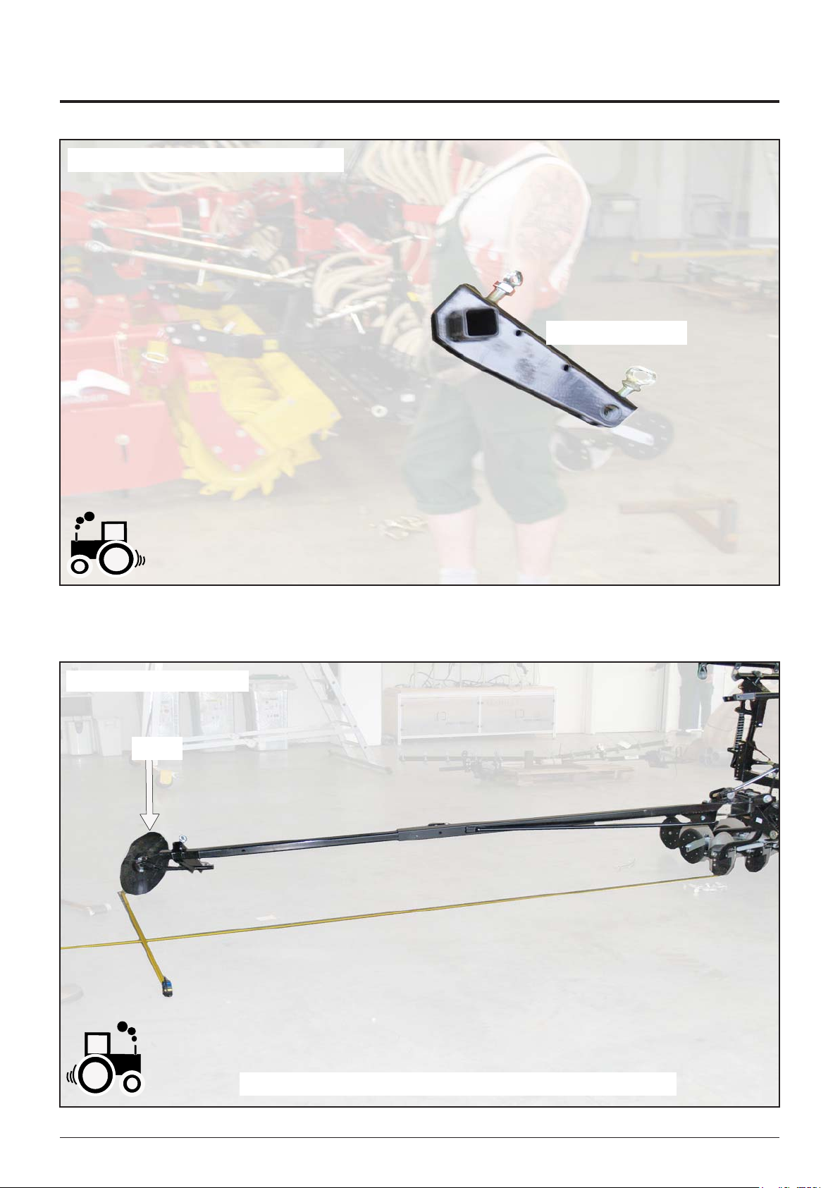
Mounting the top link and top link support
Mount the top link as shown (outside left).
Top link
8548.GB.60L.0
Mount the top link support as shown
(outside left)
Mount the top link on the support as shown.
Top link support
- 11 -

8548.GB.60L.0
Mount the top link support as shown (inside left).
- 12 -

Mount the top link as shown (inside left).
8548.GB.60L.0
Repeat the above steps analogously on the right side of the machine.
- 13 -

Mounting the track marker
Lower the arm and mount the extension.
8548.GB.60L.0
- 14 -
Mount the track marker support as shown.
8548.GB.60L.0
Track marker support
Mount the marker as shown
Marker
Repeat the above steps analogously on the other side of the machine.
- 15 -

Mount the control box and attach hoses and cables.
8548.GB.60L.0
For the assembly of the front hopper and the hoses,
see "Attaching to tractor".
- 16 -

ATTACHING TO TRACTOR
GB
Fixing devices on the tractor
- Pipe fixing hoops are included for fitting the pipe to
the tractor.
- The fixing devices (A, B, C) for fitting the pipe hoops (D)
to the tractor are not included. The mounting brackets
must be made on the spot according to the type of
tractor.
Front mounting example:
- Make fixing device (A)
and fit hoop (D).
Fitting the hoses
Cutting hoses into lengths
- Machine in lowered position (front and rear)
- Cut hoses to optimum lengths
- Fit hose connections
Connecting hose to pipe
- Place seal (E) on pipe and put together
- Clamp tight with pipe connector (F)
Centre mounting example:
- Secure pipe clamp (B) to
cabin stay and fit hoop
(D).
Rear mounting example:
- Secure fixing device (C)
to cabin and fit hoop
(D).
When laying the conveyor pipe line ensure
that it is possible to lift / lower and open
the tank cap.
0900-GB ANBAU_8548
- 17 -

ATTACHING TO TRACTOR
GB
Mounting front tank
Mounting tank to front three-point hydraulics
- Kat II or coupling triangle
- Secure properly!
Fitting front p.t.o. for the blower drive
- 1000 rpm, clockwise direction of travel
- Adapt/fit cardan shaft (see Supplement “Cardan
shaft”
Ensure that cardan shaft length is lying
horizontal and in lowered position!
Front tank and cardan shaft should lie horizontal
when in operation.
- Adjust through upper link length and lifting
height.
Connect conveyor spiral hoses
(according to “Fitting the Hoses” description)
Connect front cable assembly
- Connect plugs (S1, S2, S3) to the appropriate
sockets
Mounting the seeding rail
Fitting the seeding rail
- Fit seeding bar, which sits on supports (1), to a
soil-tilling implement.
- Secure properly!
- After lifting implement remove stand (A) by removing
linch pin (2).
Connect conveyor spiral hoses
(according to “Fitting the Hoses” description)
Connect hydraulic lines
- With hydraulic blower drive couple line to point (H)
Adjusting see chapter "Hydraulic blower drive"
Connect front cable assembly
- Connect plug (S) to the appropriate socket
Connect hydraulic lines
- Spur marker - double action
- Coulter pressure adjustment – single action
0900-GB ANBAU_8548
- 18 -

ATTACHING TO TRACTOR
GB
Mounting electronic control
- Connect 7-pole electro cable to front tank pos. (S1)
- Fit operating console in tractor cabin
Transport and working positions
Changing to transport position
Actuate the hydraulic control valve on the tractor
- Spur markers are swung in
- Secure spur markers with pin (14)
Locking bracket (15) must lock into place
0900-GB ANBAU_8548
Changing to working position
Release track marker lock
- remove bolts (14) from mounting
Further information
- see chapter ”Field Operation”
- 19 -

General notes on road transport
• Lower implement far enough to have a ground
clearance of 25-30 cm.
Advantage: centre of gravity lies lower, therefore less
danger of
tipping.
• Secure hydraulic control valve on tractor
against unintentional use!
The working unit is hydraulically locked in the transport
position
(fig. 9).
Only when the hydraulic control valve is actuated will
the lock be released again.
• Check lighting and signs
- for function
- for damage
Necessary equipment
- red/white warning board
- red reflector rear
- white reflector front
- side lamps (if necessary)
If tractor´s rear lights or direction indicators (blinkers)
are blocked by the attached implement, then alternative
devices must be used on the implement.
ATTACHING TO TRACTOR
GB
Take care when turning on slopes!
The tractor´s driving features are influenced by the weight
of the attached implement. This can lead to dangerous
situations especially on slopes.
Danger of tipping is present
• when the working unit is hydraulically raised or
lowered
• when driving through curves with working unit
raised.
Safety hints
• Reduce speed accordingly when driving
through curves
• Travelling backwards on a slope is better
than making a risky turn.
0900-GB ANBAU_8548
- 20 -

Check
EN Final Check and Self-Check
• Check all screw fittings and plug-in connections for good condition and secure fit.
• Nach Fertigstellung der Maschine sind alle Schmierstellen laut Wartungsanleitung (siehe Betriebsanleitung)
erstmalig abzuschmieren, sowie die Ölstände vorhandener Getriebe etc. zu kontrollieren und falls nötig zu
ergänzen.
Geeignete Schmierstoffe siehe Schmiermitteltabelle der Wartungsanleitung.
• Read carefully through the Operating Manual prior to starting the machine for the first time. It is imperative to
follow the safety information it contains!
1000_MA_Kontrolle_EN
- 21 -

Im Zuge der technischen Wei ter ent wick lung
D
arbeitet die PÖTTINGER Ges.m.b.H stän dig
an der Verbesserung ih rer Pro duk te.
Änderungen ge gen über den Ab bil dun gen und
Be schrei bun gen dieser Be triebs an lei tung müs sen wir
uns darum vorbehalten, ein Anspruch auf Än de run gen
an bereits aus ge lie fer ten Ma schi nen kann daraus nicht
ab ge lei tet werden.
Technische Angaben, Maße und Ge wich te sind
un ver bind lich. Irrtümer vor be hal ten.
Nachdruck oder Übersetzung, auch aus zugs wei se,
nur mit schriftlicher Ge neh mi gung der
ALOIS PÖTTINGER
Maschinenfabrik Gesellschaft m.b.H.
A-4710 Grieskirchen.
Alle Rechte nach dem Gesetz des Ur he ber recht
vor be hal ten.
La société PÖTTINGER Ges.m.b.H améliore
F
constamment ses produits grâce au progrès
technique.
C'est pourquoi nous nous réser-vons le droit de
modifier descriptions et illustrations de cette notice
d'utilisation, sans qu'on en puisse faire découler un
droit à modifications sur des machines déjà livrées.
Caractéristiques techniques, dimensions et poids sont
sans engagement. Des erreurs sont possibles.
Copie ou traduction, même d'extraits, seulement avec
la permission écrite de
ALoIS PÖTTINGER
Maschinenfabrik Gesellschaft m.b.H.
A-4710 Grieskirchen.
Tous droits réservés selon la réglementation des
droits d'auteurs.
Following the policy of the PÖTTINGER Ges.
GB
m.b.H to improve their products as technical
reserve the right to make alterations which must not
necessarily correspond to text and illustrations contained in this publication, and without incurring obligation
to alter any machines previously delivered.
Technical data, dimensions and weights are given as an
indication only. Responsibility for errors or omissions
not accepted.
Reproduction or translation of this publication, in
whole or part, is not permitted without the written
consent of the
ALoIS PÖTTINGER
Maschinenfabrik Gesellschaft m.b.H.
A-4710 Grieskirchen.
All rights under the provision of the copyright Act
are reserved.
developments continue, PÖTTINGER
PÖTTINGER Ges.m.b.H werkt permanent
NL
aan de verbetering van hun producten in het
Daarom moeten wij ons veranderingen van
de afbeeldingen en beschrijvingen van deze
gebruiksaanwijzing voorbehouden, zonder dat daaruit
een aanspraak op veranderingen van reeds geieverde
machines kan worden afgeleid.
Technische gegevens, maten en gewichten zijn niet
bindend. Vergissingen voorbehouden.
Nadruk of vertaling, ook gedeeltelijk, slechts met
schriftelijke toestemming van
ALoIS PÖTTINGER
Maschinenfabrik Gesellschaft m.b.H.
A-4710 Grieskirchen.
Alle rechten naar de wet over het auteursrecht voor-
behouden.
Por este motivo, reservamonos o direito de modificar
as figuras e as descrições constantes no presente
manual, sem incorrer na obrigação de modificar
máquinas já fornecidas.
As características técnicas, as dimensões e os pesos
não são vinculativos.
A reprodução ou a tradução do presente manual de
instruções, seja ela total ou parcial, requer a autorização
por escrito da
ALoIS PÖTTINGER
Maschinenfabrik Gesellschaft m.b.H.
A-4710 Grieskirchen
Todos os direitos estão protegidos pela lei da prop-
riedade intelectual.
kader van hun technische ontwikkelingen.
A empresa PÖTTINGER Ges.m.b.H
P
esforçase continuamente por melhorar os
seus produtos, adaptando-os à evolução
técnica.
a la evolución técnica. Por ello nos vemos obligados
a reservarnos todos los derechos de cualquier
modificación de los productos con relación a las
ilustraciones y a los textos del presente manual, sin
que por ello pueda ser deducido derecho alguno a la
modificación de máquinas ya suministradas.
Los datos técnicos, las medidas y los pesos se
entienden sin compromiso alguno.
La reproducción o la traducción del presente manual
de instrucciones, aunque sea tan solo parcial, requiere
de la autorización por escrito de
ALoIS PÖTTINGER
Maschinenfabrik Gesellschaft m.b.H.
A-4710 Grieskirchen.
Todos los derechos están protegidos por la ley de la
propiedad industrial.
La empresa PÖTTINGER Ges.m.b.H se
E
esfuerza contínuamente en la mejora
constante de sus productos, adaptándolos
La PÖTTINGER Ges.m.b.H è costantemente
I
al lavoro per migliorare i suoi prodotti
mantenendoli aggiornati rispetto allo
sviluppo della tecnica.
Per questo motivo siamo costretti a riservarci la facoltà
di apportare eventuali modifiche alle illustrazioni e alle
descrizioni di queste istruzioni per l’uso. Allo stesso
tempo ciò non comporta il diritto di fare apportare
modifiche a macchine già fornite.
I dati tecnici, le misure e i pesi non sono impegnativi.
Non rispondiamo di eventuali errori. Ristampa o
traduzione, anche solo parziale, solo dietro consenso
scritto della
ALoIS PÖTTINGER
Maschinenfabrik Gesellschaft m.b.H.
A-4710 Grieskirchen.
Ci riserviamo tutti i diritti previsti dalla legge sul diritto
d’autore.

ALOIS PÖTTINGER
Maschinenfabrik Gesellschaft m.b.H
A-4710 Grieskirchen
Telefon: 0043 (0) 72 48 600-0
Telefax: 0043 (0) 72 48 600-2511
e-Mail: landtechnik@poettinger.at
Internet: http://www.poettinger.at
GEBR. PÖTTINGER GMBH
Stützpunkt Nord
Steinbecker Strasse 15
D-49509 Recke
Telefon: (0 54 53) 91 14 - 0
Telefax: (0 54 53) 91 14 - 14
PÖTTINGER France
129 b, la Chapelle
F-68650 Le Bonhomme
Tél.: 03.89.47.28.30
Fax: 03.89.47.28.39
GEBR. PÖTTINGER GMBH
Servicezentrum
Spöttinger-Straße 24
Postfach 1561
D-86 899 LANDSBERG / LECH
Telefon:
Ersatzteildienst: 0 81 91 / 92 99 - 166 od. 169
Kundendienst: 0 81 91 / 92 99 - 130 od. 231
Telefax: 0 81 91 / 59 656
 Loading...