

Page 1
Contact:
020 72477117
[email protected]
www.pod-point.com
POD Point July 2015
PP - D - 001
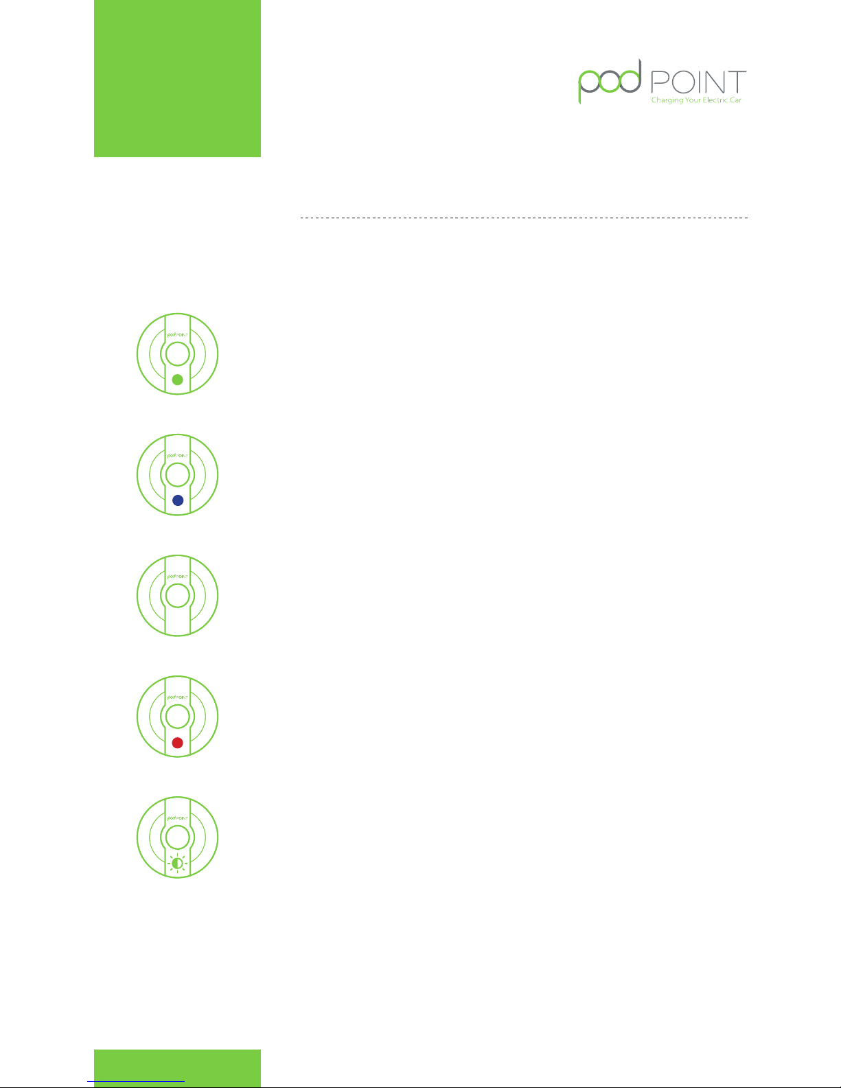
It couldn’t be easier. To start charging, plug in your car and
wait for the light to go green.
To end your charge at any time, just disconnect. The light will go blue
to let you know it’s on standby.
If the light flashes purple then your POD Point is talking to our network.
How to use your
POD Point Solo
Technical Manual POD Point
Solo Charger User Guide
In the unlikely event that the lights go red, it means something’s gone
wrong. No need to panic, just get in contact and we’ll get it sorted.
If your EV supports scheduled charging, then just plug in as soon as you
park and your car will only charge at the programmed time. The light
will flash green to show you it’s waiting to start.
No extension cords or conversion adapters are allowed to be used
with the POD Point Solo unit. Please contact POD Point, if you need to
charge a car that requires a different type of lead.
POD Point Technical Manual
1
Page 2
This guide is intended for use by competent electrical installer with the
necessary competence and experience to carry out the installation in
accordance with the local applicable regulations and legislation.
Introduction
This guide is designed to explain the basic requirements and options to be considered for the
installation of a POD Point Solo for a Mode 3 Electric Vehicle. A POD Point Solo is an electric vehicle
charging point designed for installation in indoor or outdoor locations. It is rated to IP54.
The POD Point POD Point Solo is designed and tested to meet the following European safety
& functionality standards for electrical devices. During manufacture each POD Point has been
functionality tested for safety using BS EN 61010 & BS EN 61557 approved equipment.
Important Safety Information
Warning! The Pod Point Solo charging unit is manufactured to be safe and without risk provided
they are professionally installed, used and maintained in accordance with the manufacturer’s
instructions and recommendations and installed by competent electrical installer in accordance
with the regulations and legislation applicable, e.g.: BS7671:2008 Amendment 3:2015 applicable at
the time of installation. The POD Point is designed to be connected to one AC supply only.
Locating the POD Point Solo
The installer should consult the EV owner to establish their preferred installation location. This
should take into consideration the cable length of unit/car.
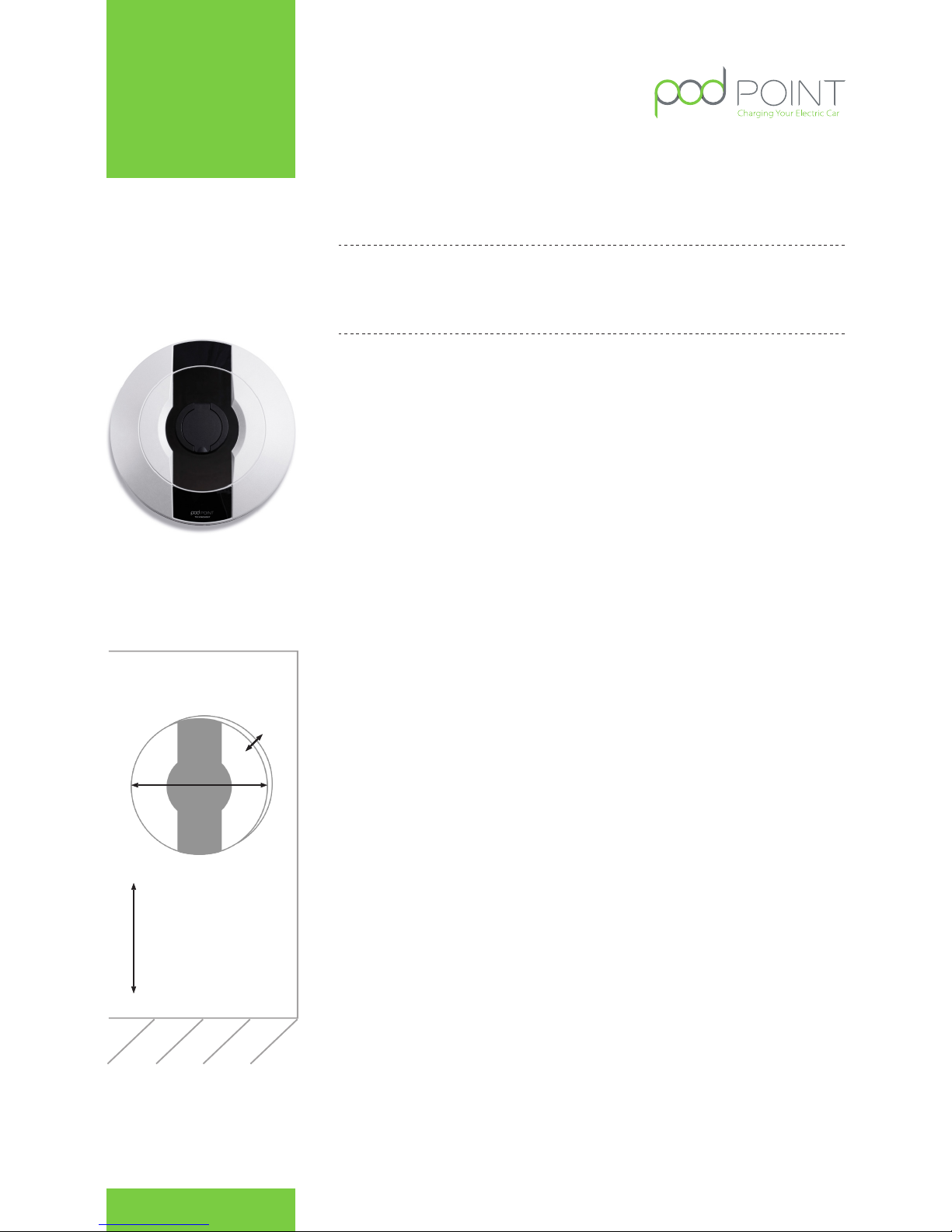
The POD Point must be mounted at a height of 750mm-1200mm to avoid vehicle impact. ( Fig. 2 )
Technical Details
The POD Point POD Point Solo is designed and tested to meet the following European safety
& functionality standards for electrical devices. During manufacture each POD Point has been
functionality tested for safety using BS EN 61010 & BS EN 61557 approved equipment. The POD
Point solo is a Class I rated device for 230V / 400V AC 50Hz systems.
Contact Us
If you have any questions, comments, or issues regarding POD Point Products which are not
covered by this installation guide, please contact our customer support team, details below. As
part of our quality and training programme calls may be recorded or monitored.
Customer Support
POD Point Limited
145 - 157 St John St
London, EC1V 4PY
Telephone: 020 7247 4114
E-mail: [email protected]
Web: www.pod-point.com
Installation Guide
750mm - 1200mm
360mm
150mm
Depth
Fig. 1 POD Point Solo Socketed Version
Fig. 2 Dimensions and
location of unit
POD Point July 2015
PP - D - 001
POD Point Technical Manual
Contact:
020 72477117
[email protected]
www.pod-point.com
2
Page 3
Earth Arrangements
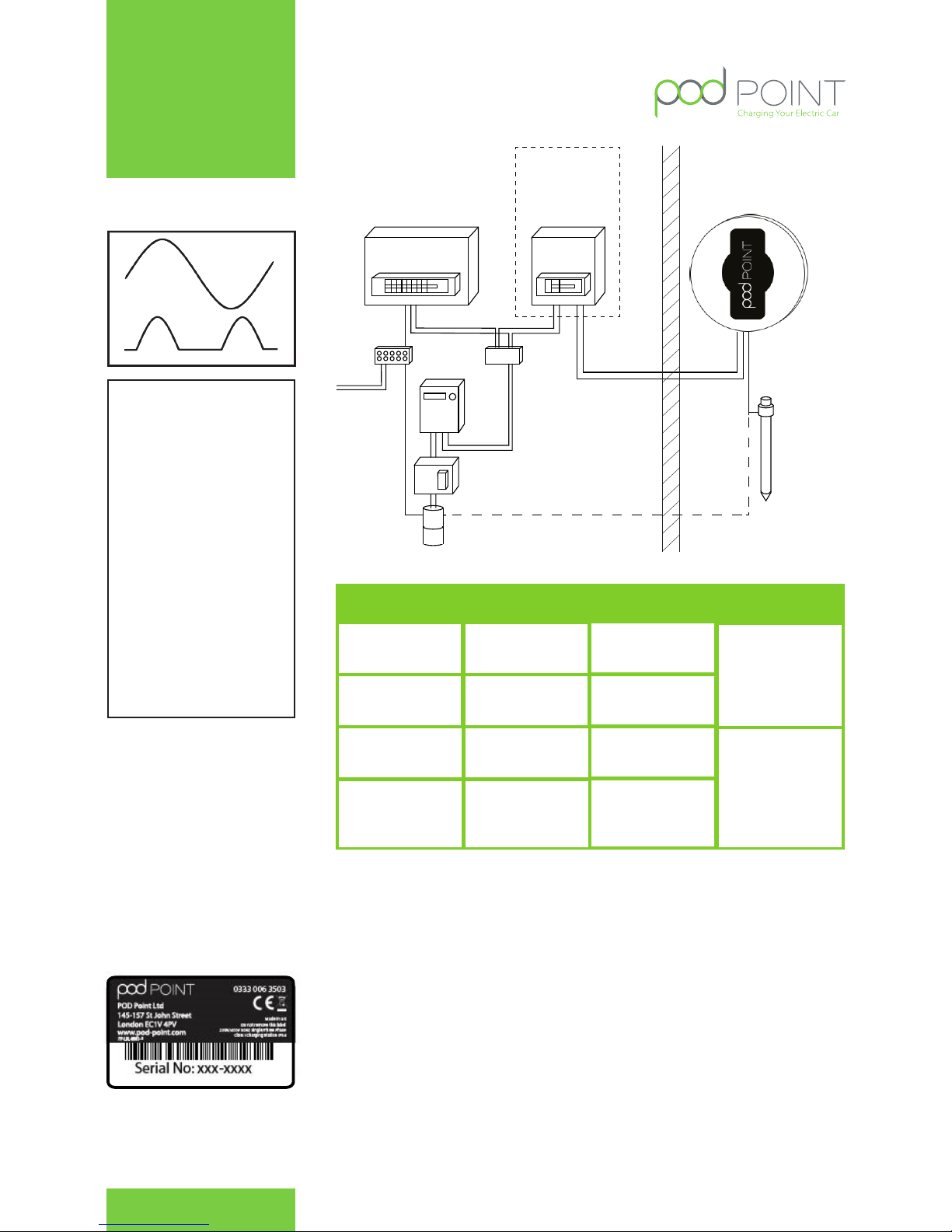
Where the home charger is to be installed outside, a separate earth electrode is required, If it can be proven
that the existing installation complies with regulation 544.14.1 (the earth of the home charger and main earth
electrode cannot exceed 70VRMS if the PEN conductor becomes open circuit) a separate earth electrode may not
be required. It is the responsibility of the installer to conduct a risk assessment of the immediate area to a range
of 10 Meters as to the safest and most reliable way to earth the POD Point Solo unit, If an adjacent installation
(within 10 meters) have a PME earthing arrangement where the POD Point Solo would be connected to an
existing TT system it is imperative that this risk assessment is conducted.If a TT earth system is required for the
POD Point Solo it shall be independent from the distributors earth system with no direct interconnection (the
incoming supply SWA protective cover (earth) should not be connected to housing or earth electrode).
The electrical installer shall install a suitable copper rod electrode complete with termination housing and covers
where appropriate. The earth connection shall be made from the electrode to the POD Point Solo via copper
conductor earth wire of an appropriate CSA for the installation.
Existing Consumer Unit
Bonding
MID
Meter
Henley
Fuse
For TN-S ONLY
Earth
Electrode
or Mat
New Consumer
Unit Type A
RCD / C Curve
MCB or RCBO
RCD / RCBO
30 mA
Type A
2 pole
30 mA
Type A
4 Pole
OutsideInside
Fig. 3. Type A RCD
Markings
Note for RCD
The IET code of practice stipulates
that all RCD’s meet BS EN61008,
BS EN61009 and BS EN60947-1or
equivalent that disconnect both
live and neutral conductors and
“specify” a Type A RCD/RCBO to
be fitted.
The minimum requirement
for the POD Point Solo is a
30mA Type A RCD is installed
in the consumer unit - (iΔn)
not exceeding 0.03A and an
operating time not exceeding
40ms at a residual current
of 5 Un. With an additional
MCB, see table on page 7 for
recommended MCB/RCBO
ratings.
MCB * / RCBO
20A ( C curve )
20A ( C curve )
3 Pole
40A ( C curve )
Cable Rating
Typically
4mm2- 6mm
2
Typically
6mm2- 10mm
2
Typically
6mm2- 10mm
2
Unit Rating
3.7kW
22.0kW
11.0kW
7.0kW
Typically
6mm2- 10mm
2
40A ( C curve )
3 Pole
Fig 5. Typical Schematic of installation
circuit
Table A. Circuit protection
* The POD Point provides internal over-current protection in addition to the this.
Fig. 4 Unit Label
Additional parts required by the
installer:
1. 3x M8 80mm screws
2. 3x Wallplugs
3. 20mm IP56 or greater
gland for the conduit
entry into the rear unit
housing dependent on the
supply method (20mm
conduit, SWA armoured cable,
flexible conduit etc.).
POD Point July 2015
PP - D - 001
POD Point Technical Manual
Contact:
020 72477117
[email protected]
www.pod-point.com
3
Page 4

The earth wire shall be installed in conduit where there is a risk of
mechanical damage or damage as a result of exposure to sunlight.
Where installations are located inside of a building and a TN-C-S
system is pre-installed and the vehicle may only be charged inside the
building the PME earth maybe used, In the case of socketed home
charger where the charge cable does not form part of the charger it
should not be installed inside a garage (customers charge cable may
enable charging outside of garage area)
In some installation additional bonding maybe required for external
metallic structures, metal garages, iron fences etc. if the vehicle or
EVSE could come into contact with the structure (i.e. if the structure
and vehicle can be touched simultaneously) .
Array systems:
In case of several charging stations connected to the same power
supply line, an additional local ground connection will have to be
ensured in order at least , every 10 outlets. The maximum resistance
for each additional ground connection (taken independently) will
have to be less than 167 ohms. All the ground lines will have to be
connected to ensure a single equi – potential zone.
Transformers
If the earth is not achievable then a transformer is required. In Mode
IT or TT> 150 Ohms: An isolating transformer with separate windings
is placed upstream EVSE. This one must then be fed in mode TN. The
Neutral feed of the transformer shall be connected to PE before the
RCD and MCB (if 2 pole MCB is used), resistance measured between
the EVSE PE and this Earth must be less than 167 ohms.
Mode IT is prohibited
All installations must comply to BS7671 regulations.
Isolation and Switching for Security and
Maintenance
To ensure that the POD Point Solo unit can be “turned off” to enhance
security and enable maintenance and repair activity, a double
pole switch (or isolator) suitably rated shall be installed within the
customer’s property in an accessible location. The switch should be
mounted at a height of between 450mm and 1200mm above finished
floor level to achieve compliance with Building Reg’s. An isolator
switch is a mandatory required for “new builds”, but optional for
existing dwellings (for additional security at customers request).
Installation Procedure
The POD Point Solo has been designed as a wall mounted
device. The installer should confirm that the wall that the unit
is intended to be fixed to is structurally appropriate for the
mounting of the POD Point Solo. The installer should identify
the construction of the wall, and identify the correct and
appropriate fixings to use.
• The Installer has a duty of care to ensure that the POD
Point Solo unit is securely attached to the wall or
structure where the unit is intended to be operated
from.
• Once the location and height of the POD Point Solo
unit has been decided, the installer can begin marking
the wall with indicator points to locate the unit. Use drilling
template to locate the holes.
• Before drilling commences ensure that the installation
wall has been checked for electric cabling or pipework
with a suitable detector.
• It is highly recommended this is done prior to any
installation work commencement (drilling of fitting of
conduit etc) to allow the customer to visualise where
the unit will be installed. Once the installation site is
marked up, confirm with the customer this meets their
expectations.
Drilling the Holes for the Electrical Supply
Cable Entry
As the electrical supply to the POD Point Solo may be fed from a
number of directions; the unit has been designed to accept supply
conduit entry on either the left or right sides or via rear entry (if supply
wiring has already been chased into the wall)
The installer should drill a suitable hole for the cable entry grommet/
adapter to be used to accept the electrical supply cables in EITHER the
left, right or rear of the unit (depending on direction that the electrical
supply approaches). Flat surfaces have been provided at either side
of the unit for ease of drilling. Once drilled the installer should fit an
appropriate cable gland or conduit adapter for the type of conduit
being used to supply the unit.
When drilling the case:
1. Only drill in the flat surfaces provided on the left, right or
rear of the unit. Do not drill on any curved surface.
2. Take care not to damage any wiring or components inside
the case. Place a suitable stop (e.g. block of wood) inside
the case when drilling to prevent accidental damage.
3. If any of the wiring or components are damaged during
installation DO NOT CONNECT OR SWITCH ON THE POWER
before consulting with POD Point.
4. The wall can now be drilled for the 3 mounting holes and
depending on the wall structure solid/dry lined or stud
partition, appropriate fixings can be used to fit the unit to
the wall. Do not drill with the unit in position as masonry
dust may damage the unit. Use the recommended drilling
template included in the box.
5. The rear of the unit should then be fitted to the wall by
fitting the top/upper screw first so the remaining 2 screws
positions can be easily aligned and fitted.
6. Once fitted in place, the rear unit should be securely fixed
flush to the wall.
POD Point July 2015
PP - D - 001
POD Point Technical Manual
Contact:
020 72477117
[email protected]
www.pod-point.com
4
Page 5
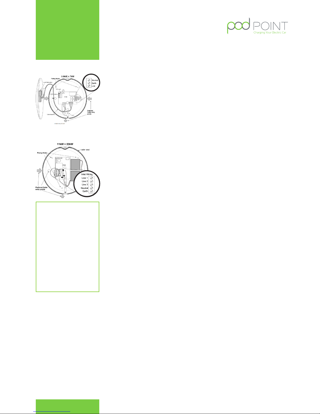
Wiring up the POD Point Solo
( See Fig 7-8 )
• With the rear unit securely fitted to the wall, the electrical
supply connection can be made.
• As the installation route of the wiring will vary with each
installation, the rear unit has been designed to accept
supply conduit entry on either the left, right sides or via rear
entry.
• The choice of entry point used will determine the amount
of insulation that needs to be cut away for the internal
wiring connection of the unit. The diagram below
illustrates the connection terminals for the electrical supply
cables.
Ensure that power cables are connected to the appropriate terminal as follows:
• Live 1: Brown
• Live 2: Black ( 3 - Phase Units Only )
• Live 3: Grey ( 3 - Phase Units Only )
• Neutral: Blue
• Earth: Green/Yellow
All of the cables that are to be connected into the supply terminals should have their insulation
stripped back 12~15mm to provide good contact to the screw terminals/jaws.
Before final assembly is performed an earth loop impedance test and polarity check shall be
performed at the unit connections to confirm the installation is sound.
Commissioning/Registering the unit
Domestic/OLEV installs
On power up of the POD Point Solo the LED’s on the front should illuminate in white. When the Communications
module has initialised the LED’s should change to magenta. When the unit has registered with the Pod Point
server the LED’s should then go blue with a short magenta flash. This process may take several minutes
depending on GSM network and server load.
If the LED’s remain white for a prolonged period of time there may be no GSM signal or the sim card is not
inserted correctly.
Public places installs
Visit the PP Install App to commission this unit.
Fitting the front of the Unit
Once the rear unit has been fitted, the wiring to the unit connected and tested, the front cover can be fitted in
place. Prior to fitting the front cover, visually check the internal connections, remove any debris that may have
entered the unit during installation and check that the front cover mating seal is in place. Place the cover on the
housing, using the top fixing as a point of reference, the front cover can then be secured in place at 5 points. The
unit is supplied with both pozidriv and T15 pin torx screws if additional security is required.
Final Electrical Testing
To meet the BS7671 (17th edition) requirements for testing of an electrical installation, the following tests and
checks shall be performed by a competent electrical installer before during or after a POD Point Solo unit is
installed:
• A visual inspection of the installation including the existing electrical installation.
• Verification of the characteristics of the electrical supply at the origin of the installation to
confirm the supply is suitable for the additional load.
• A test to confirm the continuity of the circuit protective conductors.
• A test to confirm the integrity of the circuit insulation resistance.
• A test to confirm the polarity of the installation is correct.
• Where applicable a test to confirm the earth electrode resistance is within acceptable
tolerances (or)
• An earth fault loop impedance test
• A test of the mechanical operation of residual current devices (RCD’s)
• A test to confirm the operation of residual current devices (RCD’s) is within stipulated
timescales (at the rated current and at five times the rated current operating current.)
• A test or calculated measurement of the prospective fault current.
• A verification of the functional operation of the POD Point Solo unit
Fig 7. Wiring of 1-Phase
Solo unit
Fig 8.Wiring of 3-Phase
Solo unit
In accordance with ‘Part P’ of the Building
Regulations (England & Wales) all notifiable
electrical installation work performed in domestic
dwellings must be carried out by a competent
electrical installer registered with a government
approved Part P Competency Scheme or
subjected to verification by the local building
control department. In Scotland all work must
be carried out by an electrical installer registered
with a Building Standards Scheme such as those
run by SELECT or the NICEIC.
NOTE: In England & Wales the installation of a
new circuit or a connection point for equipment
outside of the equipotential zone is notifiable.
Note for
commisioning
If you do not have access to the App,
please text the details listed below to this
phone number: 07805888545
• Site operator’s name
• Site operator’s email address
• Site operator’s phone
number
• Location of the unit
• Name of the unit (e.g.: John-
Mary)
• PG-number of the unit (e.g.:
PG - 90001)
POD Point July 2015
PP - D - 001
POD Point Technical Manual
Contact:
020 72477117
[email protected]
www.pod-point.com
5
Page 6
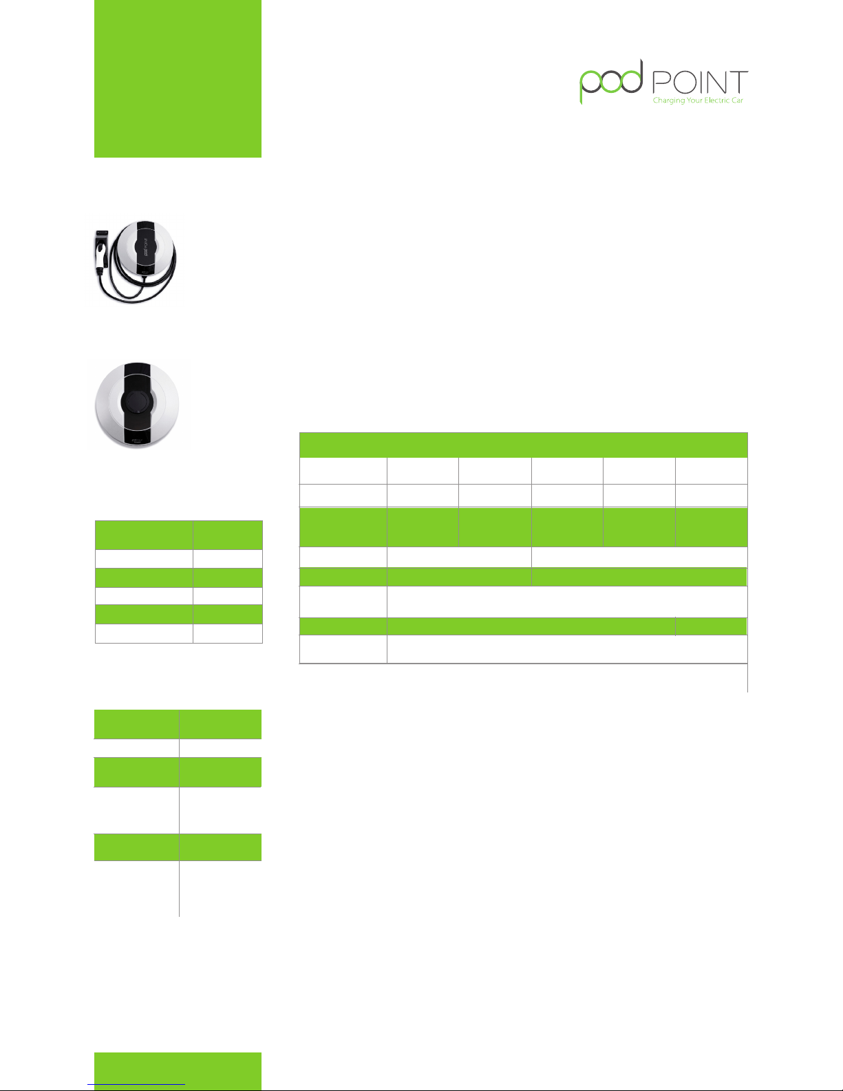
Dimensions
Ø=360mm,
depth=150mm
Grey & Black
5kg
95% Non Cond
IP54
-30°C to +50°C
Standard Colour
Shipping Weight
Operating Temp
Operating Humidity
Enclosure Rating
Installation
POD Point Solo’s are designed for installation in either open air or protected environments. The
product should be installed by a certified electrician and uses industry-standard mechanical
fittings and electrical connections. POD Point can, in some territories, provide a turn-key service for
the installation and commissioning of charge points. Note that to validate the product warranty,
installation shall be done in accordance with POD Point’s guidance and all relevant legislation.
Compatibility
POD Point Solo units are compatible with the Mode 3 charging standard and have been tested
with the vehicles listed in the Vehicle Compatibility Section
Connectors and Power Ratings
POD Point Solo units are available with a SAE J1772 gun on a 4.8m attached cable, a IEC 62196
gun on a 4.8m attached cable or with a IEC 62196 Socket with the Mode 3 charging standard.
Status lights
The status of the charge point is shown by coloured status lights.
Management Information System Compatible
Communicating variants of Solo are compatible with the POD Point MIS.
Pay-as-you-go Compatible
Communicating variants of Solo are compatible with the POD Point Pay-As-You-Go system.
Warranty
All correctly installed POD Point hardware is covered by our thirty six month limited warranty.
Any hardware failure should be promptly reported to us, ideally by e-mail to enquiries@pod-point.
com, or by calling our support team on 0207 247 4114 quoting the serial number, location of the
product, and giving a brief description of the failure.
Our support team will then investigate, and attempt to remotely resolve the issue. They may ask
you to provide additional information to assist in this.
If the issue cannot be resolved remotely, and the product is in warranty, we will make
arrangements for one of our team to visit the location and, if the issue is a result of any
shortcoming in design or manufacture it will be made good free of charge or, at our option,
exchanged for a replacement product.
If we attend site, and the fault is not a result of a shortcoming in design or manufacture of our
product, we will make reasonable attempts to suggest what the issue is, and propose a resolution
which may have a fee associated with it. A call out fee will be applicable where our product is not
at fault.
Limitation of liability
In no event will we accept any liability for any loss, costs or damage consequential on the use
and/or misuse of our hardware products except and only to the extent that this is caused by our
negligence.
POD Point Solo
Single Phase
Part Number
Communicating Variants
Rated output
Rated current
Holster Yes
Yes
N/A
Charge
Protocol
GPRS comms
ready
Mode 3
3.6kW
16A
30A
7kW
Socket Electrical
compliance
SAE J1772
on 4.8m
Cable
IEC 62196
on 4.8m
Cable
SAE J1772
on 4.8m
Cable
IEC 62196
on 4.8m
Cable
IEC 62196
Socket
S3-1C
S3-2C
S7-1C
S7-2C S7-UC
POD Point Single Phase Solo Datasheet POD Point July 2015
PP - D - 001
Rated Voltage
230V AC
Single Phase
50Hz
To be fitted
at source
30mA Type A
RCD/ RCBO to be
fitted at source
LVD 2006/95/EC
EMC 2004/108/EC
EN 61851 -1 and 22
CE Certified
5W
Rated Frequency
Over current
protection
Earth leakage
protection
Standby power
consumption
Standards
compliance
Physical Properties
Electrical Specification
Cable
Universal
PPoint Model
S3S3 IEC 62196 IEC 62196IEC 62196
Contact
020 7247 4114
www.pod-point.com
6
Page 7
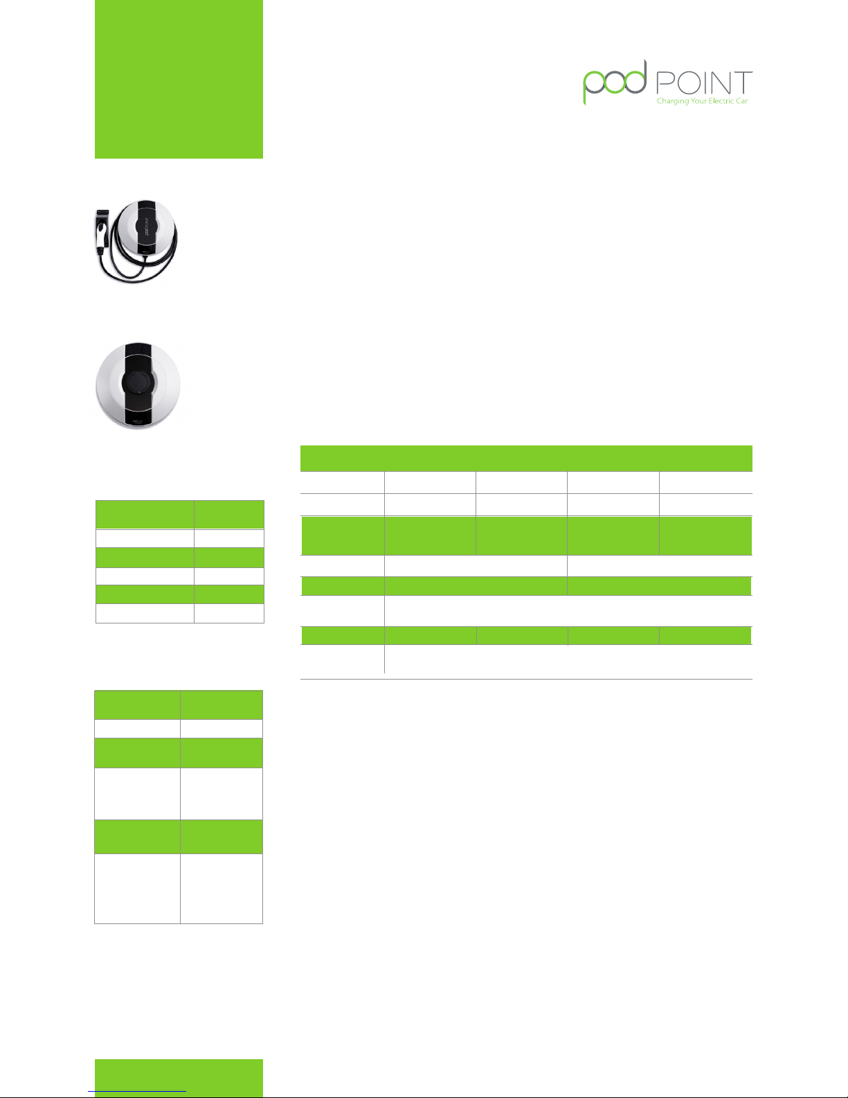
Dimensions
Ø=360mm,
depth=150mm
Grey & Black
6.5kg
95% Non Cond
IP54
-30°C to +50°C
Standard Colour
Shipping Weight
Operating Temp
Operating Humidity
Enclosure Rating
Installation
POD Point Solo’s are designed for installation in either open air or protected environments. The
Solo should be installed by a certified electrician and uses industry-standard mechanical fittings
and electrical connections. POD Point can, in some territories, provide a turn-key service for the
installation and commissioning of charge points. Note that to validate the product warranty,
installation in accordance with POD Point’s protocols and local regulations must be verified
Compatibility
POD Point Solo units are compatible with the Mode 3 charging standard. Three phase products
can charge three phase vehicles or single phase vehicles.
Connectors and Power Ratings
POD Point Solo ( three phase ) units are available with a IEC 62196 gun on a 4.8m attached cable, or
with a IEC 62196 Socket.
Status lights
The status of the charge point is shown by coloured status lights.
Management Information System Compatible
Communicating variants of Solo are compatible with the POD Point MIS.
Pay-as-you-go Compatible
Communicating variants of Solo are compatible with the POD Point Pay-As-You-Go system.
Part Number
Communicating Variants
Rated output
Rated current
Holster
N/A
Yes
Charge
Protocol
GPRS comms
ready
Mode 3
11kW
16A x 3 Phase 30A x 3 Phase
22kW
Socket Electrical
compliance
IEC 62196
Captive Cable
IEC 62196
Socket
IEC 62196
Socket
IEC 62196
Captive Cable
S11 - UC
Rated Voltage
415V AC
Three Phase
50Hz
To be fitted
at source
30mA type A
RCD / RCBO to
be fitted at source
LVD 2006/95/EC
EMC 2004/108/EC
EN 61851 -1 and 22
CE Certified
5W
Rated Frequency
Over current
protection
Earth leakage
protection
Standby power
consumption
Standards
compliance
Physical Properties
Electrical Specification
IEC 62196
Cable
Universal
PPoint Model
S11S11 S22 S22
N/A
YES
YES
S22 - 2CS22 - UCS11 - 2C
Warranty
All correctly installed POD Point hardware is covered by our thirty six month limited warranty.
Any hardware failure should be promptly reported to us, ideally by e-mail to enquiries@pod-point.
com, or by calling our support team on 0207 247 4114 quoting the serial number, location of the
product, and giving a brief description of the failure.
Our support team will then investigate, and attempt to remotely resolve the issue. They may ask
you to provide additional information to assist in this.
If the issue cannot be resolved remotely, and the product is in warranty, we will make
arrangements for one of our team to visit the location and, if the issue is a result of any
shortcoming in design or manufacture it will be made good free of charge or, at our option,
exchanged for a replacement product.
If we attend site, and the fault is not a result of a shortcoming in design or manufacture of our
product, we will make reasonable attempts to suggest what the issue is, and propose a resolution
which may have a fee associated with it. A call out fee will be applicable where our product is not
at fault.
Limitation of liability
In no event will we accept any liability for any loss, costs or damage consequential on the use
and/or misuse of our hardware products except and only to the extent that this is caused by our
negligence.
POD Point Three Phase Solo Datasheet POD Point July 2015
PP - D - 001
Contact
020 7247 4114
www.pod-point.com
POD Point Solo
Three Phase
7
Page 8

Warranty
Don’t worry, your POD Point is
covered by a comprehensive
3 year warranty so if it breaks,
and it was installed by us,
we’ll fix or replace it.
If you have any problems just pick up the phone and our
support team will help you out.
Alternatively let us know by e-mail. Quote the serial number
of your POD Point (the ‘PSL’ number on the bottom of the
unit) and a brief description of what happened.
Our contact details are on the back cover of this booklet.
POD Point July 2015
PP - D - 001
POD Point Technical Manual
Contact:
020 72477117
[email protected]
www.pod-point.com
8
 Loading...