

Page 1
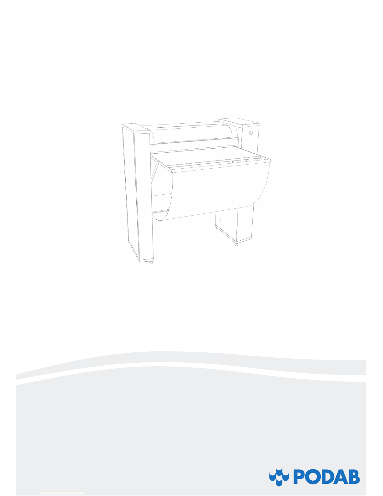
Cold ironer KM 752
Installation, operation manual and
spare parts list
Page 2
2
©PODAB 2018
Thank you for choosing the cold ironer KM 752 from PODAB. We
hope that it will be of great use for you and ask you kindly to read
the instructions carefully.
IMPORTANT!
FOR YOUR SAFETY: the information in this manual must be followed to prevent property damage and personal injury.
NOTE: The paragraphs marked “WARNING” and “CAUTION” appearing in this manual are not meant to cover all possible conditions and situations that may occur. It is very important that water and electricity are handled with great care and respect, by both
installation technicians and end users.
Page 3

3
©PODAB 2018
Contents
Safety regulations 4
Important safety instructions 4
Installation 5
Dimensions and specifications 5
Technical information 5
Before you start 5
Installation of the cold ironer 6
Place the cold ironer 6
Electrical installation 6
Function control 6
Maintenance 7
Clean the cold ironer 7
Replace the iron cloth 7
Control the oil level 7
User manual 8
Controls 8
Before you start 9
Start 9
Stop 9
Reverse/release 9
When you are finished 9
Cold ironing techniques 9
If the cold ironer stops 9
Spare parts list 10
Electrical drawing 12
Notes 13
Page 4
4
©PODAB 2018
Safety regulations
1. Read all instructions before using the cold ironer.
2. Do not allow children to play on or around the cold ironer.
Close supervision is necessary when the cold ironer is used
near children. This is a safety rule for all appliances.
3. Do not reach for or touch the rollers when they are moving
or when they are at rest.
4. Do not install or store the cold ironer where it will be exposed to water and/or weather.
5. Do not tamper with the controls.
6. To reduce the risk of an electric shock or fire, DO NOT use
an extension cord or an adapter to connect the cold ironer
to the electrical power source.
7. ALWAYS disconnect the cold ironer from electrical supply
before service. Disconnect the power cord by grasping the
plug, not the cord.
8. Install the cold ironer according to the INSTALLATION
INSTRUCTIONS. All connections for electrical power
and earthing must comply with local codes. Licensed
personnel must be engaged when required.
9. Keep after the cold ironer. If it is exposed for violence there
is a risk that certain security functions will stop working.
Please contact your nearest service partner if you are unsure of the cold ironer’s status.
10. If the electrical cable is damaged, it must immediately be
changed by a person with electrical authorization.
11. Never operate the cold ironer with any guards and/or panels removed.
12. If the cold ironer is not assembled after the manufacturer’s
instructions, there is a risk that the cold ironer can cause
personal injuries or injuries on property.
NOTE: The WARNING and IMPORTANT SAFETY INSTRUCTIONS appearing in this manual are not meant to cover all
possible conditions and situations that may occur. Common
sense, caution and care must be exercised when installing,
maintaining, and operating the cold ironer. Always contact
your dealer, distributor, service agent or the manufacturer
about problems or conditions you do not understand.
WARNING
Indicates hazardous situation that, if not avoided, could cause
severe personal injury.
CAUTION
Indicates hazardous situation that, if not avoided, could cause
minor personal injury or property damage.
(Save the following instructions)
Throughout this manual you will find text warnings in text
boxes: “WARNING” and “CAUTION”. In these boxes you will
find the safety measurements you will have to take; end user,
service staff or installation staff.
You will also find precautions marked: IMPORTANT and NOTE.
These are followed by information of what should be considered.
IMPORTANT: to inform the reader of special steps that must
be taken in order to prevent injuries on the cold ironer.
NOTE: to inform what is important to know, but it cannot
cause personal injuries or injury on the cold ironer.
Important safety instructions
WARNING
To minimize the risk of fire, electrical shock, personal injuries
or death when the cold ironer is in use the following
precautions must be followed:
Page 5
5
©PODAB 2018
Installation
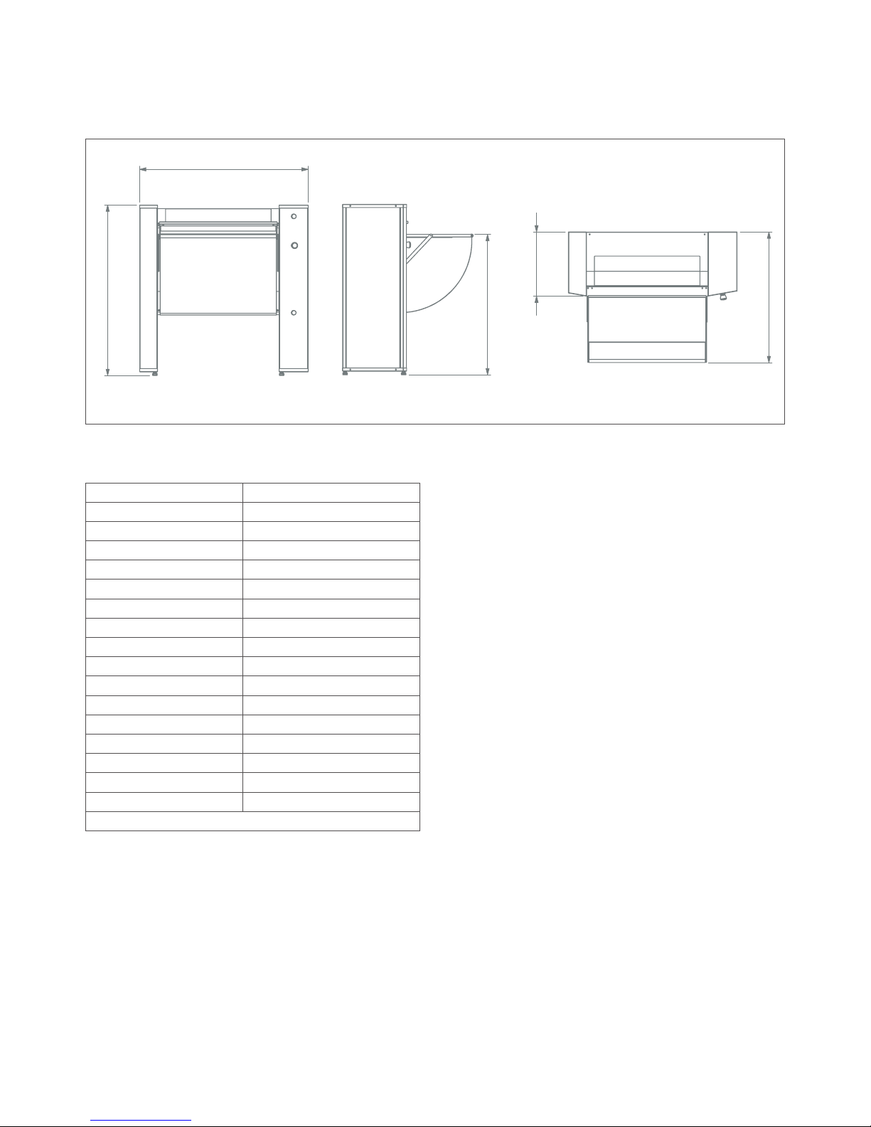
Dimensions and specifications
Before you start
Tools
You need the following tools to easily install the cold ironer
KM 752:
• Cross head screwdriver
• Wrench
• Level
• Torx driver
Electricity demands
The cold ironer is build to be connected to 3-N, 400 V, 50 Hz and a
10 A fuse. Other voltage on demand.
NOTE: If the cold ironer is delivered when it is below 0ºC,
it should be kept inside until it reaches room temperature
before it is turned on.
Roller width, mm 730
Roller diameter, mm 120
Roller speed, v/min 14
Roller pressure, kg/cm² 560
Iron cloth length, mm 2500
Weight, kg 90
Width, mm 1060
Depth max, mm 820
Depth min, mm 403
Height, mm 1070
Height to table, mm 880
Connection 3~N, 400 V, 50 Hz
Fuse, A 10
Total effect, kW 0,37
Motor effect, kW 0,37
Power cable, mm² 5 x 1,5
Art no 151110
*Average pressure measured inside iron cloth is 150 kg/cm²
Technical information
1060
1070
880
403
820
1060
1070
880
880
Page 6
6
©PODAB 2018
Place the cold ironer
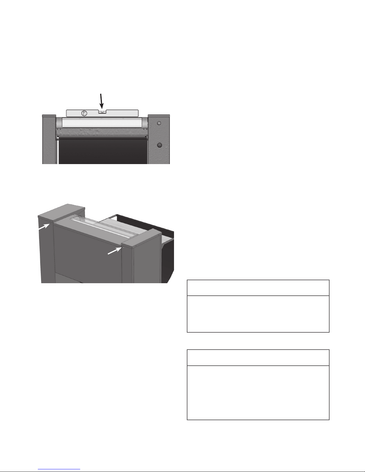
1. Place the cold ironer in position on a solid, sturdy and level
floor. Installing the cold ironer on any type of carpeting,
soft tile, platform or other weakly supported structures is
not recommended. Place a level on the top of the ironer
and check if the cold ironer is level from side to side and
front to back.
2. Lift up the feeding table; attach it to the two supports at the
base of the ironer.
3. Secure the cold ironer to the wall or anchor it to the floor.
IMPORTANT: Always secure the cold ironer to a wall or to
the floor.
NOTE: If the cold ironer is delivered when it is below 0ºC,
it should be kept inside until it reaches room temperature
before it is turned on.
Electrical installation
Hard wire the cold ironer to a power switch.
The cold ironer must be earthed. In the event of malfunction or
breakdown, earthing will reduce the risk of electric shock. The
cold ironer must be properly earthed in accordance with all local
codes and ordinances. If the laundry room’s electrical supply
does not meet the above specifications and/or if you are not sure
that the laundry room has an effective earth, have a qualified
electrician or your local electrical utility company check it and
correct it if needed.
WARNING
It is extremely important that the cold ironers finger protection and emergency stop are in function. It can lead to
severe personal injuries if the safety devices are out of
order.
WARNING
To reduce the risk of fire, electric shock, serious injury
or death, all wiring and earthing MUST abide with local
electrical codes. It is the customer’s responsibility to have
the wiring and fuses checked by a qualified electrician to
make sure the laundry room has adequate electrical power to operate the cold ironer.
Installation of the cold ironer
Electrical connection 400V / 3N / 50 Hz
Fuse 10 A
Total effect 0,37 kW
NOTE: This cold ironer is factory-wired for a 400 Volt electrical supply.
NOTE: The machine must be connected in the correct
phase sequence in order to start. KM 752 is equipped with
a phase sequence protection relay. A green light will be lit
on the relay when the sequence is correct.
Function control
4. Turn on the power switch
5. Start the ironer by pushing the ON/OFF button
6. Start the process by flipping the manoeuvre shield down,
to the position Start/forward. Make sure that the rollers
are moving in the right direction and the iron cloth is fed
into the rollers.
7. Control the finger protection by flipping the manoeuvre
shield down closer to the rollers. The ironer should stop
immediately.
8. Control the lift and release function by flipping the manoeuvre shield up, to the position Reverse/release. The
rollers turn counter-clockwise and are separated after a
few seconds.
9. Restart the ironer by flipping the manoeuvre shield down,
to the position Start/forward. Control the emergency stop
by pushing the red button. To reset the emergency stop,
turn it clockwise.
Page 7
7
©PODAB 2018
Clean the cold ironer
Use a damp cloth and mild soap when cleaning the cold ironer.
Do not use scouring pads or abrasive cleansers. The rollers
need no particular care.
Replace the iron cloth
Under normal conditions, the iron cloth should be replaced every second year.
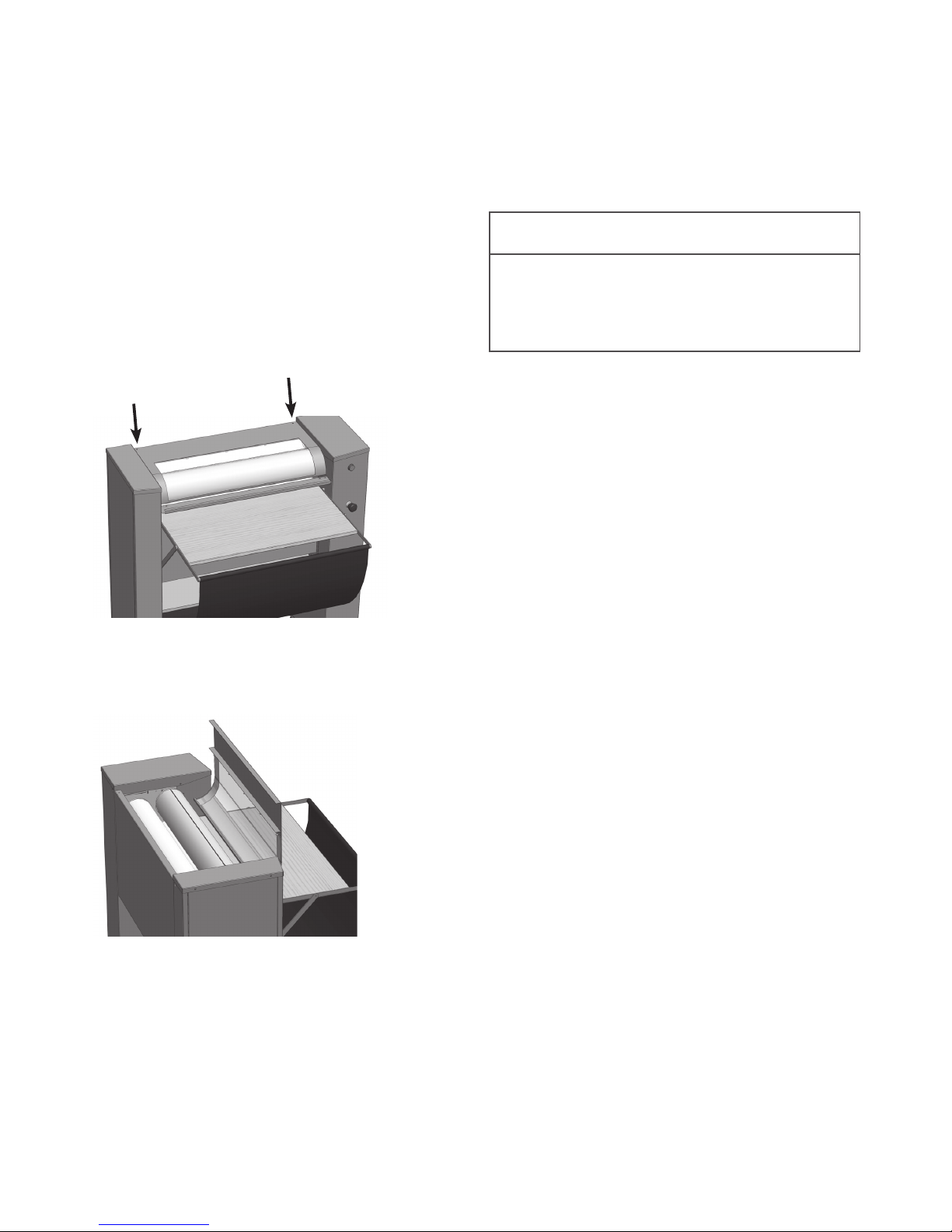
1. Place the manoeuvre shield in the position Reverse/
release. Pull out the entire iron cloth.
2. Turn off the incoming power.
3. Remove the two screws that secures the top cover.
4. Flip the manoeuvre shield down, into a horizontal position.
Openthe top cover and let it rest against the manoeuvre
shield.
5. Remove the old iron cloth from the slot of the top roller.
6. Fit the new iron cloth in the slot with the hem facing the
rear of the cold ironer.
7. Reinstall the top cover and turn on the power.
8. Place the manoeuvre shield in the position,
START/FORWARD and roll up the new iron cloth.
Maintenance
Control the oil level
Check the level of oil in the worm gearbox yearly. The gear box
is placed on the right side of the ironer. Remove the plug on the
right side of the motor to check the oil level.
WARNING
To reduce the risk of fire, electric shock, serious injury or
death, always disconnect the incoming power to the cold
ironer before service and maintenance.
Page 8
8
©PODAB 2018
Controls
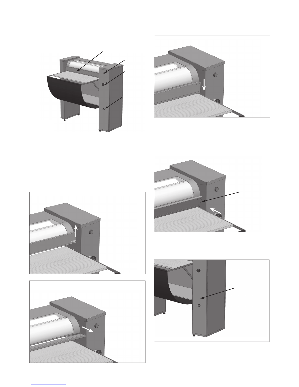
ON/OFF switch
To operate the manoeuvre shield the ON/OFF switch must be in
the position ON. It is indicated by a green light.
Manoeuvre shield
The cold ironer is operated by the manoeuvre shield. The
manoeuvre shield can be placed i three positions.
Reverse/release - Stop - Start/forward
User manual
Finger protection
The manoeuvre shield is also working as finger protection for
the user. If the shield is flipped down to close to the rollers,
the rollers immediately stop. When flipped back to the forward
position, the rollers move again.
Motor protection
If the motor is overloaded it will stop. Press the button for overload protection to restart the motor.
ON/OFF
Emergency
stop
Reseting of
motor overload
protection
Reseting of
motor overload
protection
Finger
protection
REVERSE
Reverse/release
STOP
Stop
FORWARD
Forward
Manoeuvre shield
Page 9
9
©PODAB 2018
Before you start
To achieve the best possible result when ironing, the laundry shall
be lightly moist. Never iron textiles with buttons, zippers etc.
Start
Make sure that the power switch is on. Decide which type of
ironing method to use by consulting the section “ Cold ironing
techniques”
Flip down the manoeuvre shield and let the moving rollers grab
your textiles. Keep the textiles and the iron cloth tensioned
during the complete process.
In you want to pause the process flip the manoeuvre shield up
to the position Stop.
When the complete textile is fed into the rollers, let the cold
ironer work for 2-3 minutes (skip this step when ironing using
the technique “Ironing without iron cloth”).
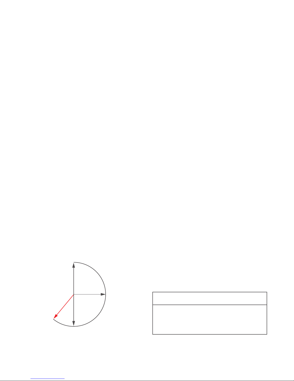
Stop
Flip the manoeuvre shield up to the horizontal position to make
the rollers stop. This stop function should not be confused
with the finger protection function.
Reverse/release
When the manoeuvre shield is flipped to the position,
Reverse/release the cold ironer reverse. After a few seconds the
rollers separate, and the textiles can easily be taken out.
When you are finished
Always leave the iron cloth to dry freely in the collecting tray
under the feeding table.
Leave the manoeuvre shield in the horizontal position, Stop.
Turn off the power switch.
Cold ironing techniques
There are several techniques to use when cold ironing. In the
section below we present the most common techniques.
Cold ironing on the inside of the iron cloth
Napkins, towels and other small to normal sized textiles are
ironed inside the iron cloth. The iron cloth is pulled out entirely.
Place the textile on the iron cloth, close to the rollers. Flip the
manoeuvre shield down to the position, Start/forward. Feed the
textile into the iron cloth, evenly. Iron the textile for 2-3 minutes.
Cold ironing on the outside of the iron cloth
Larger textiles such as bed linens, table cloths etc. are ironed on
the outside of both roller and iron cloth. The iron cloth should be
wrapped around the roller. Make sure that the iron cloth is fed
onto the roller evenly. Leave a few decimeters of iron cloth out,
to attach the textile to be ironed. Place the textile directly on the
iron cloth that is sticking out. Flip the manoeuvre shield down to
the position, Start/forward. The top part of the textile is fed into
the iron cloth and the rest of the textile wraps around the outside
of the rollers. Pull gently on the textile to reduce wrinkles.
Cold ironing without the iron cloth
Very large textiles should be ironed with the iron cloth completely wrapped around the rollers. Place the textile between
the roller with the iron cloth and the aluminium roller below. The
textile is ironed and falls down into the collecting tray under the
feeding table. Repeat the procedure until satisfaction.
If the cold ironer stops
The cold ironer stops if it is overloaded. Follow the instructions
below; if the cold ironer stops during the process of ironing or if
the rollers does not move when using the manoeuvre shield.
• The cold ironer is equipped with an input stop. When the rollers
are overloaded with textiles, the cold ironer stops. Flip up
the manoeuvre shield to the position, Reverse/release.
Remove the textiles by hand. Iron less textiles or change ironing technique and try again.
• If what stated above does not work, the motor might be overloaded. This occurs when too heavy textiles are fed into the
rollers. To reset the motor overload protection, push the blue
button on the right side of the ironer.
• If none of the above works. Check the emergency stop.
Reset the emergency stop by turning the handle clock-wise.
WARNING
Do not reach for or touch the rollers when they are moving or when they are stopped. - Risk for severe squeezing.
Do not allow children to play on or around the cold ironer.
DO NOT bypass any safety devices.
REVERSE
STOP
FORWARD
STOP
Page 10
10
©PODAB 2018
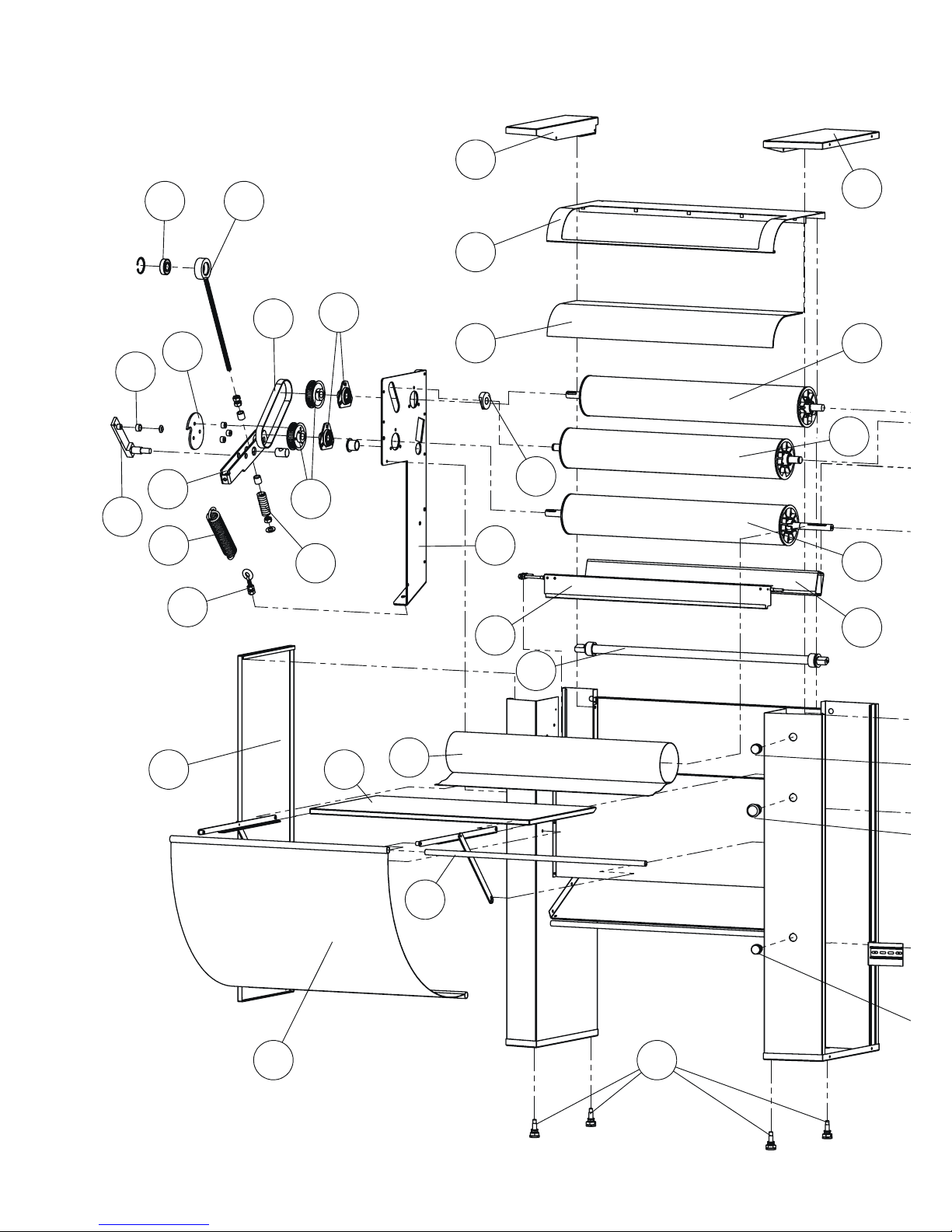
Spare parts list
1
2
3
4 5
6
7
8
9
10
35 38
36
36
28
3131
28
27
33
32
34
2423
22
11
15
14
16161616
20
21
13
12
2828
3737
17
18
19
25
29
30
26
Page 11
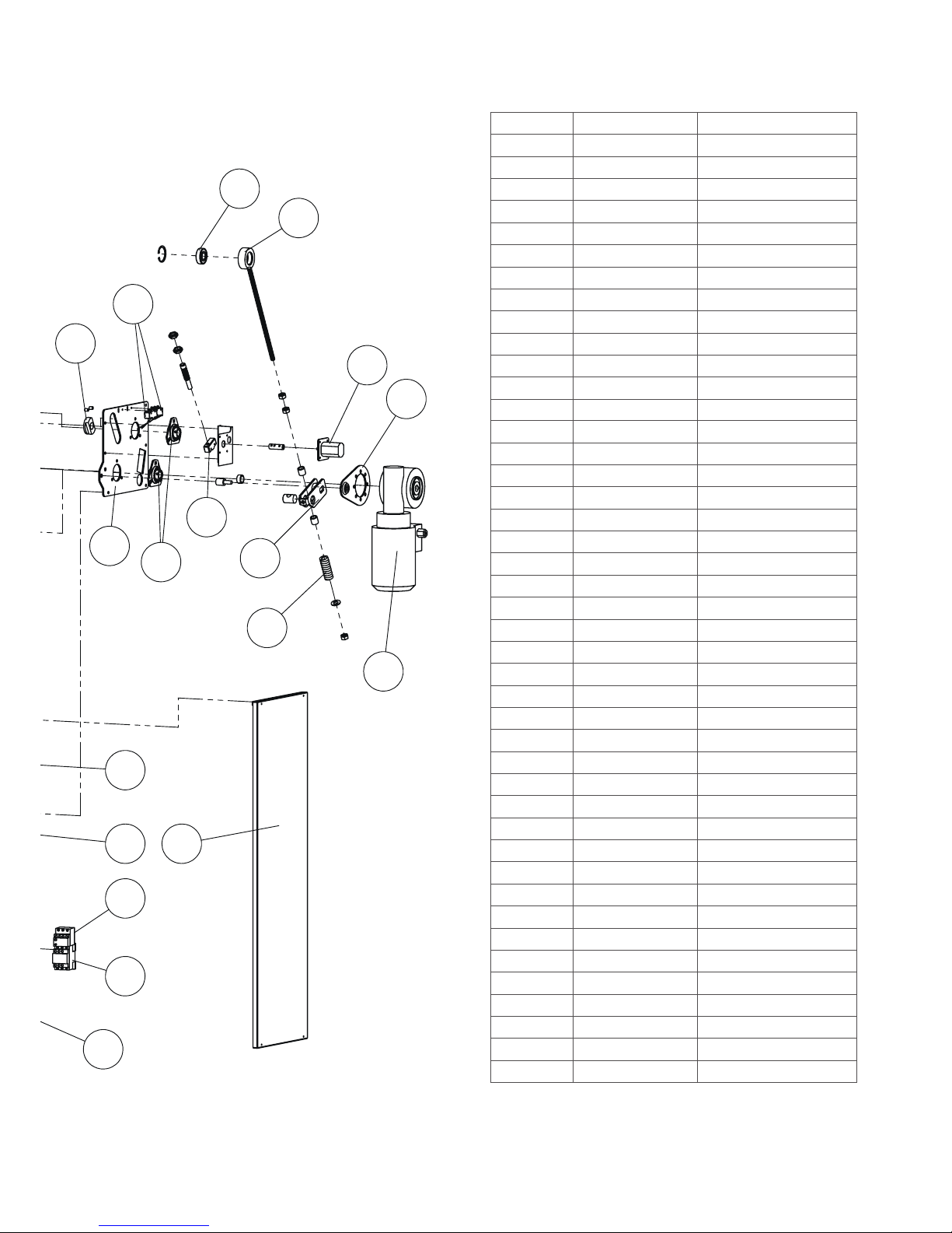
11
©PODAB 2018
36
24
23
41
42
40
39
22
20
21
2828
43
33
3737
17
18
19
Nr Art Nr Description
1
7580 Left lid
2
7581 Right lid
3
7582 Top
4
7583 Plexiglas
5
7510 Top roll
6
7511 Cloth roll
7
7512 Motor roll
8
7584 Beam
9
7585 Door
10
7586 Shaft
11
7587 Side panel left
12
7545 Cloth table
13
E200010 Cloth
14
7542 Rod
15
7539 Nylon cloth
16
7517 Foot
17
7547 Switch button, green
18
7548 Emergency stop button
19
7549 Thermal protection button
20
7588 Thermal protection motor 1-1,7A
21
504142 Contactor 230V 12A
22
7589 Side panel right
23
7526 Ball bearing 6204
24
7590 Support bearing
25
7591 Catch bushing
26
7573 Catch disc
27
7532 Belt
28
7514 Bearing
29
7572-2 Catch
30
7592 Shaft
31
7534 Belt pulley
32
7593 Spring
33
7594 Spring
34
7595 Support
35
7596 Roll support left
36
7597 Roll bushing
37
7598 Micro switch
38
7599 Roll support right
39
7560 Micro switch
40
7561 Support
41
7562 Motor support
42
7515 Motor, including gearbox
43
7563 Support
Page 12
12
©PODAB 2018
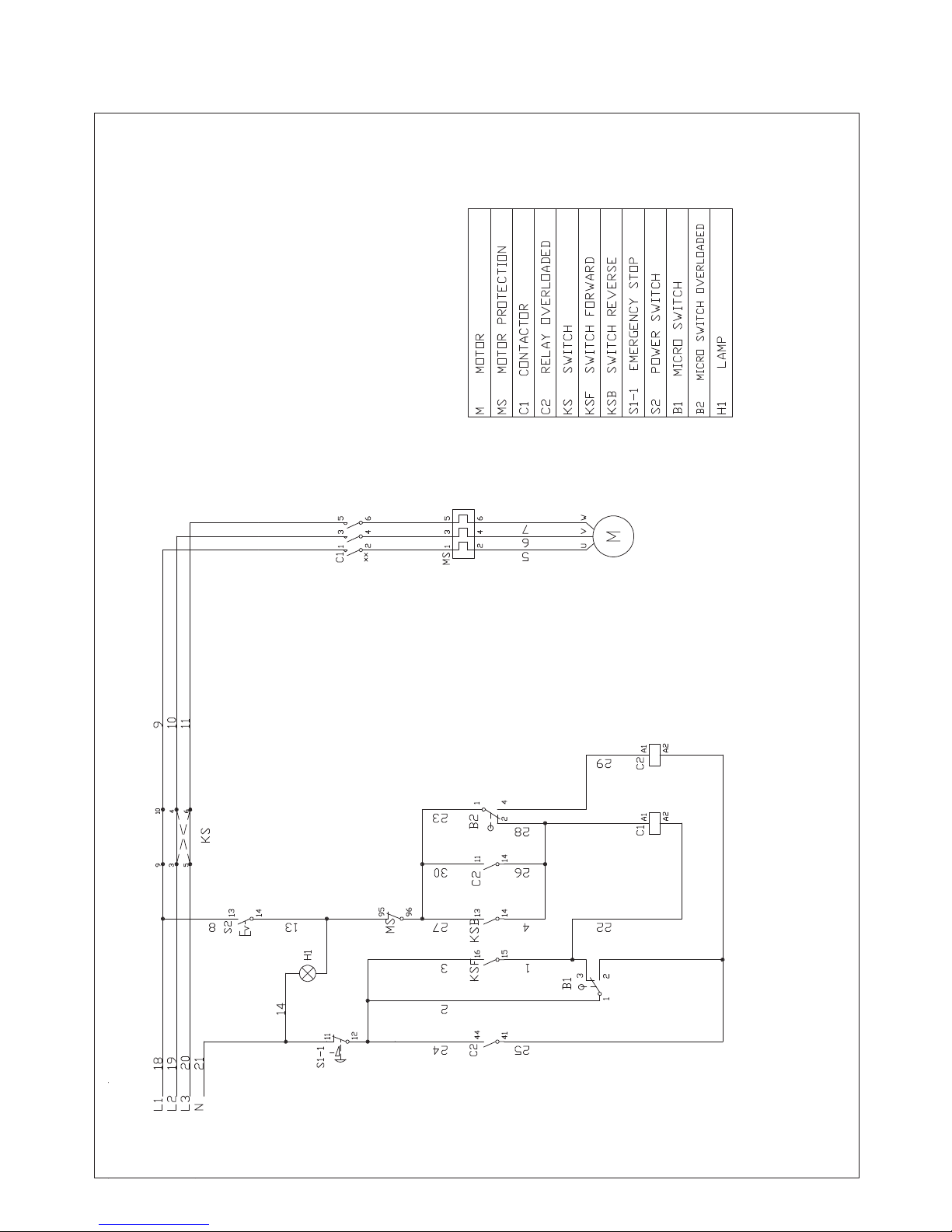
Electrical drawing
Page 13
13
©PODAB 2018
Notes
Page 14
14
©PODAB 2018
Page 15
15
©PODAB 2018
Page 16

AB PODAB, Ekonomivägen 9, 436 33 Askim, SWEDEN
Tel +46 (0)31-752 01 00, Fax +46 (0) 31-752 01 50 E-post: [email protected], www.podab.se
©PODAB 2018-08-15
SERVICE/SUPPORT
Phone +46 31-752 01 00
Fax +46 31-752 01 50
E-mail [email protected]
www.podab.se
 Loading...