

PNY 8200, GF8200A User Manual

Preface
Copyright
This publication, including all photographs, illustrations and software, is protected under international copyright laws, with all rights
reserved. Neither this manual, nor any of the material contained herein, may be reproduced without written consent of the author.
Version 1.0
Disclaimer
The information in this document is subject to change without notice. The manufacturer makes no representations or warranties with
respect to the contents hereof and specifically disclaim any implied warranties of merchantability or fitness for any particular purpose.
The manufacturer reserves the right to revise this publication and to make changes from time to time in the content hereof without
obligation of the manufacturer to notify any person of such revision or changes.
Trademark Recognition
Microsoft, MS-DOS and Windows are registered trademarks of Microsoft Corp.
NVIDIA is a registered trademark of NVIDIA Corporation.
Other product names used in this manual are the properties of their respective owners and are acknowledged.
Federal Communications Commission (FCC)
This equipment has been tested and found to comply with the limits for a Class B digital device, pursuant to Part 15 of the FCC Rules.
These limits are designed to provide reasonable protection against harmful interference in a residential installation. This equipment
generates, uses, and can radiate radio frequency energy and, if not installed and used in accordance with the instructions, may cause
harmful interference to radio communications. However, there is no guarantee that interference will not occur in a particular
installation. If this equipment does cause harmful interference to radio or television reception, which can be determined by turning the
equipment off and on, the user is encouraged to try to correct the interference by one or more of the following measures:
. • Reorient or relocate the receiving antenna
. • Increase the separation between the equipment and the receiver
. • Connect the equipment onto an outlet on a circuit different from that to which the receiver is
. connected
. • Consult the dealer or an experienced radio/TV technician for help
Shielded interconnect cables and a shielded AC power cable must be employed with this equipment to ensure compliance with the
pertinent RF emission limits governing this device. Changes or modifications not expressly approved by the system’s manufacturer
could void the user’s authority to operate the equipment.

Declaration of Conformity
This device complies with part 15 of the FCC rules. Operation is subject to the following conditions:
. • This device may not cause harmful interference, and
. • This device must accept any interference received, including interference that may cause undesired
operation.
Canadian Department of Communications
This class B digital apparatus meets all requirements of the Canadian Interference-causing Equipment Regulations.
Cet appareil numérique de la classe B respecte toutes les exigences du Réglement sur le matériel brouilieur du Canada.
About the Manual
The manual consists of the following:
Chapter 1 Describes features of the motherboard.
Introducing the Motherboard
Go to Page
Chapter 2 Describes installation of motherboard components.
1
Installing the Motherboard
Go to Page 7
Chapter 3 Provides information on using the BIOS Setup Utility.
Using BIOS
Go to Page 27
Chapter 4 Describes the motherboard software
Using the Motherboard Software
Go to Page 45
Chapter 5 Provides information about SATA RAID Setup
Setting Up NVIDIA RAID Configuration Go to Page 51

TABLE OF CONTENTS
Chapter 1
Introducing the Motherboard
Introduction…........................................................................................1
Feature ...................................................................................................2
Motherboard Components….….............................................................4
Chapter 2
Installing the Motherboard
Safety Precautions.....................................................................................7
Choosing a Computer Case…...................................................................7
Installing the Motherboard in a Case........................................................7
Checking Jumper Settings.........................................................................8
Setting Jumpers……………...........................................................8
Checking Jumper Settings
Jumper Settings
...............................................................................9
Connecting Case Components…….…….................................................10
Front Panel Header..........................................................................12
Installing Hardware..................................................................................13
Installing the Processor
Installing Memory Modules
Installing a Hard Disk Drive/CD-ROM/SATA Hard Drive
Installing a Floppy Diskette Drive
Installing Add-on Cards
Connecting Optional Devices
Connecting I/O Devices...........................................................................25
….…........................................................9
......................................................................13
.................................................................14
……..………...18
........................................................19
.....................................................................20
...............................................................22
Chapter 3
Using BIOS
About the Setup Utility.............................................................................27
Entering the Setup Utility
Updating the BIOS
Using the BIOS………….…...................................................................29
Advanced Setup
Advanced Chipset Setup
Integrated Peripherals……..………………………………………….35
Power Management Setup…………………………..............................36
The Standard Configuration................................................................27
Standard CMOS Setup……….............................................................30
…….…………...........................................27
.............................................................................29
…………………………..…....................................32
.......................................................................33

PCI/PNP Configuration…….…………………….............................38
PC Health Status...............................................................................39
Frequency/Voltage Control……………………….............................41
Load Default Settings….....................................................................42
Supervisor Password…………………………..................................42
User Password………………………..............................................43
Save & Exit Setup…..........................................................................43
Exit Without Saving……………........................................................43
Chapter 4
Using the Motherboard Software
About the Software CD-ROM..................................................................45
Auto-installing under Windows XP/Vista..........................................45
Manual Installation……………………….........................................50
Utility Software Reference……………….........................................50
Running Setup………………..............................................................................46
Chapter 5
Setting Up NVIDIA RAID Configuration
Setting Up a Non-Bootable RAID Array.................................................51
Setting Up a Bootable RAID Array…….................................................51

Chapter 1
Introducing the Motherboard
Introduction
Thank you for choosing the GF8200A motherboard. This motherboard is a high performance, enhanced function motherboard that
supports socket for AMD Phenom
high-end business or personal desktop markets.
This motherboard is based on NVIDIA
desktop platform solution. GeForce8200 is a single-chip, highly integrated, high performance HyperTransport peripheral controller,
unmatched by any other single chip-device controller. The memory controller supports DDR2 memory DIMM frequencies of 1066*
(AM2+)/800/667/533/ 400. It supports four DDR2 sockets with maximum memory size of 32 GB*
PCI Express x16 slot, two PCI Express x1 slots, 12 USB
2.0 ports (6 USB ports and 3 USB 2.0 headers support additional 6 USB ports) and SATA support with RAID function.
There is an advanced full set of I/O ports in the rear panel, including PS/2 mouse and keyboard connectors, one VGA port, one HDMI
port, one eSATA port, six USB ports, one LAN port and audio jacks for microphone, line-in and 6/8-ch (optional) line-out. This
motherboard is designed in an ATX form factor using a four-layer printed circuit board and measures 305 mm x 220 mm.
TM
processor (socket AM2+)/AMD AthlonTM 64 X2 Dual-Core/AthlonTM 64/ SempronTM processors for
®
GeForce8200 (MCP78S) Premium media and communications processor (MCP) for best
2. High resolution graphics via one
* 1. Due to the limitation of AMD CPU spec, please refer to Memory QVL for more information.
2. Due to the DRAM maximum size (2 GB per dimm) at present, thememory maximum size we have tested is 8 GB.
Feature
Processor
. • Accommodates AMD Phenom
64/SempronTM processors
. • Supports HyperTransport
This motherboard uses a socket AM2+/AM2 that carries the following features:
TM
HyperTransport
information at much higher speeds than currently available interconnect technologies.
Technology is a point-to-point link between two devices, it enables integrated circuits to exchange
TM
processor (socket AM2+) AMD Athlon
TM
(HT) 3.0 interface speeds
TM
64 X2 Dual-Core/Athlon
TM
Chipset
. • HyperTransport 3.0 x16 up and down links to the AMD socket AM2+/ AM2 CPU
. • PCI Express 16-lane link interface for external graphics processors
. • PCI Express Generation 2.0 compatible
. • Integrated NVIDIAGeForce
. • Compliant with PCI v2.3 interface at 33 MHz
. • Integrated SATA 3.0 Gb/s Host Controller
. • Twelve USB 2.0 ports supported
. • Fast ATA-133 IDE controller
. • NVIDIA
. • Integrated Hybird SLI technology, NVIDIA
multi-display technology capability
The NVIDIA® GeForce8200 is a single-chip with proven reliability and performance.
®
Series DirectX 10 Vertex Shader 4.0 graphics processor
®
MediaShieldTM RAID with support for RAID 0, RAID 1, RAID 0+1, RAID 5, and JBOD
®
UltraShadowTM technology, full NVIDIA® nView®
Memory
. • Supports DDR2 1066 (AM2+)/800/667/533/400 DDR2 SDRAM with Dual-channel architecture
. • Accommodates four unbuffered DIMMs
. • Up to 8 GB per DIMM with maximum memory size up to 32 GB*
Audio (Optional)
The onboard Audio provides either of the following features:
1
. • 5.1 Channel High Definition Audio Codec
. • DACs Support 96K/48K/44.1KHz DAC sample rate
. • Power support: Digital:3.3V; Analog:5.0V
. • WOW
. • Provides single ended CD input with DRM solutions and legacy OS issues
. • 7.1 Channel High Definition Audio Codec
. • SPDIF In/Out supports 96K/48K/44.1KHz plus SPDIF OUT supports 88.2 KHz
. • Power support: Digital:3.3V; Analog:5.0V
. • MAxx Player
. • Provides single ended CD input with DRM solutions and legacy OS issues
TM
and True SurroundTM from SRS
TM
from Waves
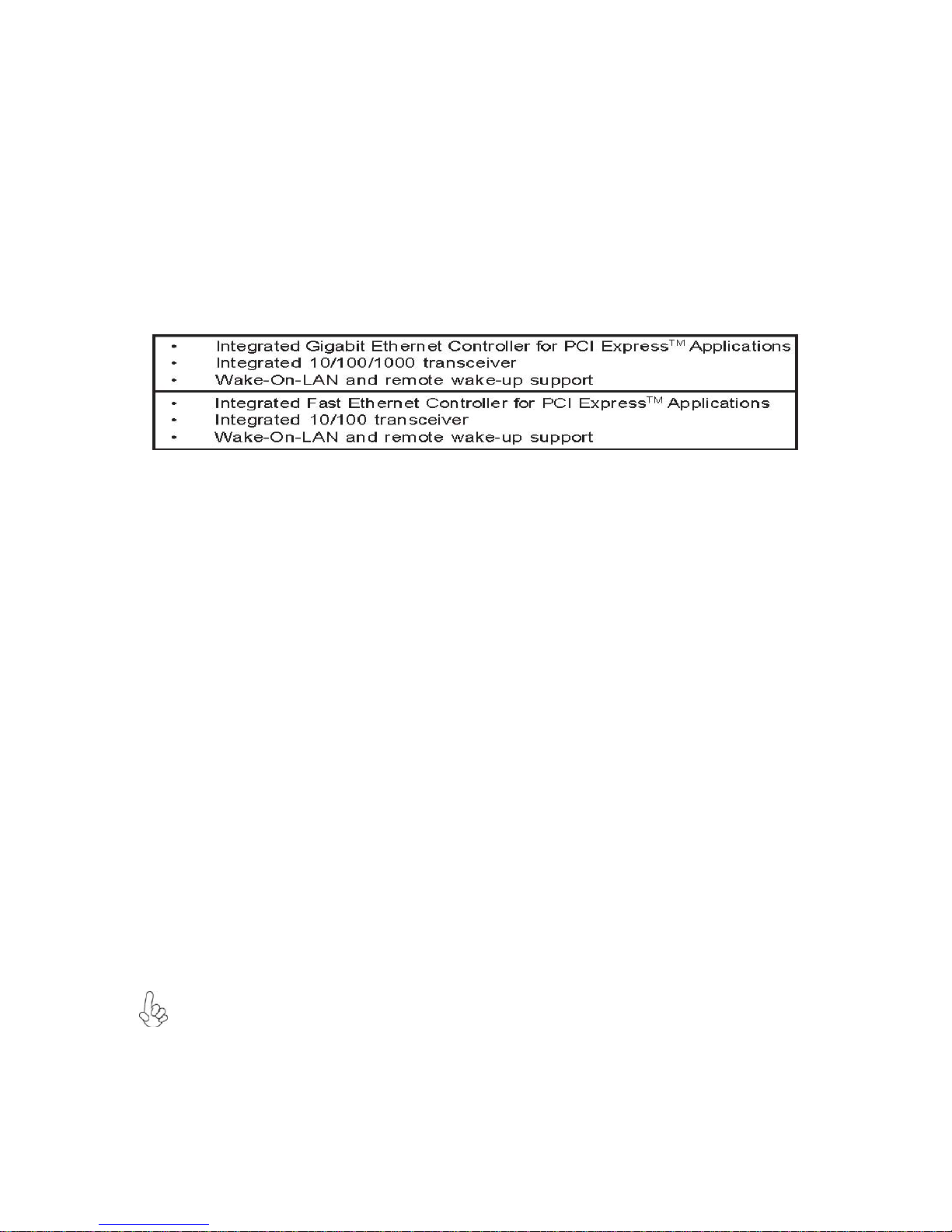
Onboard LAN (Optional)
The onboard LAN provides either of the following features:
Expansion Options
:The motherboard comes with the following expansion options:
. • One PCI Express x16 slot for Graphics Interface
. • Two PCI Express x1 slots
. • Three 32-bit PCI v2.3 compliant slots
. • One IDE connector supporting up to two IDE devices
. • One floppy disk drive interface
. • Five 7-pin SATA connectors
This motherboard supports Ultra DMA bus mastering with transfer rates of 133/ 100/66/33 Mb/s.
Integrated I/O
The motherboard has a full set of I/O ports and connectors:
. • Two PS/2 ports for mouse and keyboard
. • One VGA port
. • One HDMI port
. • One eSATA port
. • Six USB ports
. • One LAN port
. • Audio jacks for microphone, line-in and 6/8-ch (optional) line-out
BIOS Firmware
The motherboard uses AMI BIOS that enables users to configure many system features including the following:
. • Power management
. • Wake-up alarms
. • CPU parameters
. • CPU and memory timing
The firmware can also be used to set parameters for different processor clock speeds.
1. Some hardware specifications and software items are subject to change without prior notice.
2. Due to chipset limitation, we recommend that motherboard be operated at ambiance temperature between 0 and 50 °C.
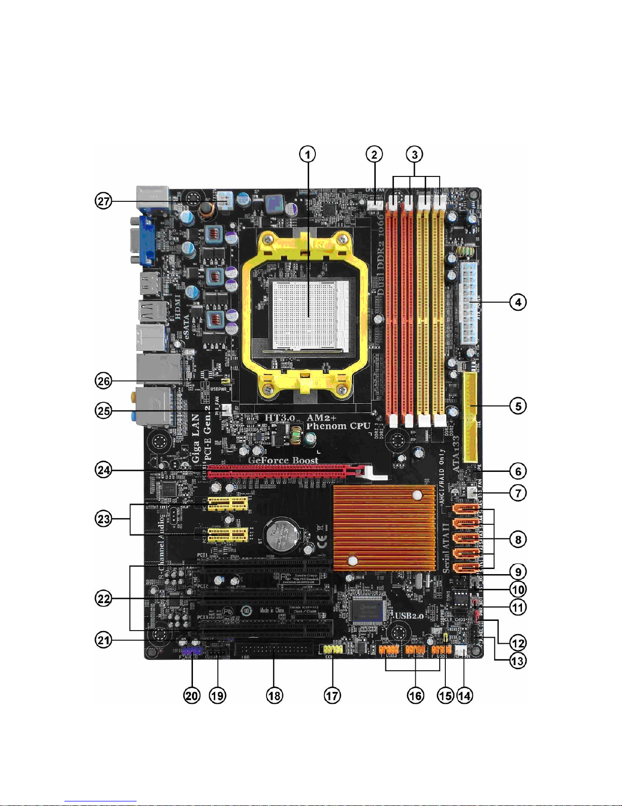
Motherboard Components

Table of Motherboard Components
LABEL CO MPO NENTS
1. CPU Socket
2. CPU_FAN CPU cooling fan connector
3. DDR2_1~4 240-pin DDR2 SDRAM slots
4. AT X_POWER Standard 24-Pin ATX Power connector
5. IDE Primary IDE connector
6. SPK Internal speaker header
7. SYS_FAN System cooling fan connector
8. SAT A1~5 Serial AT A connectors
9. IR Infrared header
10. RST _BOT Reset button
11. PWR_BOT Power o n button
12. CLR_CMOS Clear CMOS jumper
13. F_PANEL Front Panel Switch/LED header
14. NB_FAN Northbridge cooling fan connector
15. USBPWR_F Front Panel USB Power Select jumper
16. F_USB1~3 Front Panel USB headers
17. COM Onboard Serial port header
18. FDD Floppy disk drive connector
19. CD_IN Analog Audio Input connector
20. F_AUDIO Front Panel Audio header
21. SPDIFO SPDIF out header
22. PCI1~3 32-bit add-on card slots
23. PCIE1~2 PCI Express x1 slots
24. PCIEX16 PCI Express x16 graphics card slot
25. PWR_FAN Power cooling fan connector
26. USBPWR_R Rear USB/PS2 Power Select jum per
27. AT X12V 4-pin +12V power connector
Socket for AMD Phenom
AthlonTM 64 X2 Dual-Core/AthlonTM 64/SempronTM processors
TM processor (socket AM2+)/AMD
This concludes Chapter 1. The next chapter explains how to install the motherboard.

Chapter 2
Installing the Motherboard
Safety Precautions
. • Follow these safety precautions when installing the motherboard
. • Wear a grounding strap attached to a grounded device to avoid damage from static electricity
. • Discharge static electricity by touching the metal case of a safely grounded object before working on
the motherboard
. • Leave components in the static-proof bags they came in
. • Hold all circuit boards by the edges. Do not bend circuit boards
Choosing a Computer Case
There are many types of computer cases on the market. The motherboard complies with the specifications for the ATX system case.
Firstly, some features on the motherboard are implemented by cabling connectors on the motherboard to indicators and switches on
the system case. Make sure that your case supports all the features required. Secondly, this motherboard supports one or two floppy
diskette drives and two enhanced IDE drives. Make sure that your case has sufficient power and space for all drives that you intend to
install.
Most cases have a choice of I/O templates in the rear panel. Make sure that the I/O template in the case matches the I/O ports installed
on the rear edge of the motherboard.
This motherboard carries an ATX form factor of 305 x 220 mm. Choose a case that accommodates this form factor.
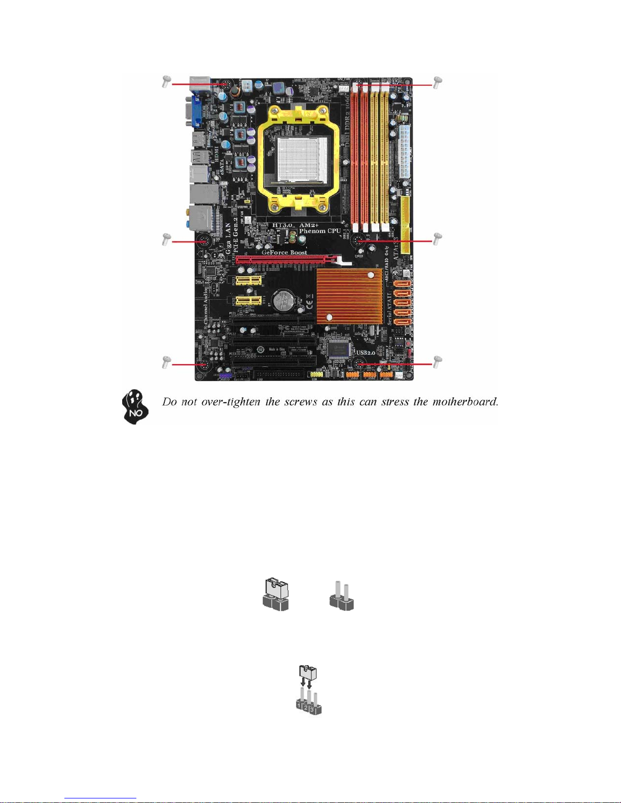
Installing the Motherboard in a Case
Refer to the following illustration and instructions for installing the motherboard in a case.
Most system cases have mounting brackets installed in the case, which correspond the holes in the motherboard. Place the
motherboard over the mounting brackets and secure the motherboard onto the mounting brackets with screws.
Ensure that your case has an I/O template that supports the I/O ports and expansion slots on your motherboard.
Checking Jumper Settings
This section explains how to set jumpers for correct configuration of the motherboard.
Setting Jumpers
Use the motherboard jumpers to set system configuration options. Jumpers with more than one pin are numbered. When setting the
jumpers, ensure that the jumper caps are placed on the correct pins.
The illustrations show a 2-pin jumper. When the jumper cap is placed on both pins, the jumper is SHORT. If you remove the
jumper cap, or place the jumper cap on just one pin, the jumper is OPEN. SHORT OPEN
This illustration shows a 3-pin jumper. Pins 1 and 2 are SHORT
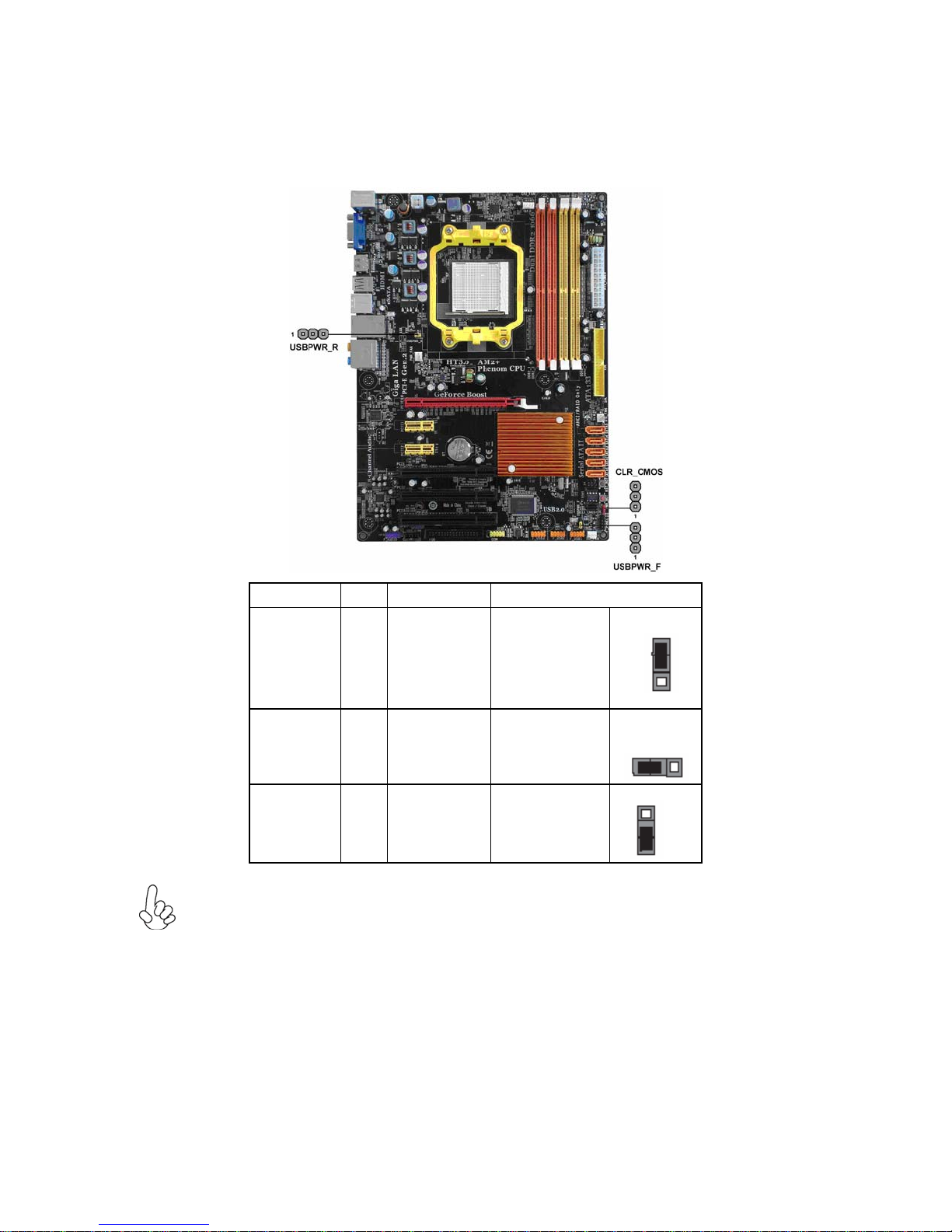
Checking Jumper Settings
The following illustration shows the location of the motherboard jumpers. Pin 1 is labeled.
Jumper Type Description Setting (default)
1-2: NORMAL
2-3: CLEAR
CLR_CMOS
USBPWR_R
USBPWR_F
3-pin CLEAR CMOS
3-pin
3-pin
Rear USB/PS2
Power Select
Jumper
Front Panel USB
Power Select
Jumper
Before clearing the
CMOS, make sure
to turn the system
off.
1-2: VCC5 2-3:
VCC5_DUAL
1-2: VCC5 2-3:
VCC5_DUAL
CLR_CMOS
1
USBPWR_R
1
USBPWR_F
1
1. To avoid the system instability after clearing CMOS, we recommend users
to enter the main BIOS setting page to “Load Optimized Defaults” and then “Save &
Exit Setup”.
2. Make sure the power supply provides enough VCC5_DUAL voltage before
selecting the VCC5_DUAL function.
3. It is required that users place the USBPWR_F & USBPWR_R cap onto
2-3 pin rather than 1-2 pin as default if you want to wake up the computer by USB/PS2
KB/Mouse.
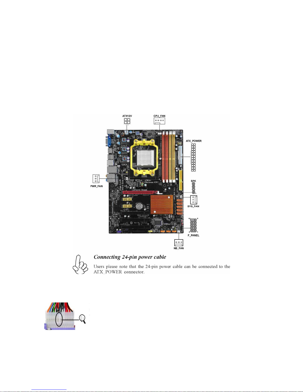
Connecting Case Components
After you have installed the motherboard into a case, you can begin connecting the motherboard components. Refer to the
following:
1 Connect the CPU cooling fan cable to CPU_FAN.
2 Connect the system cooling fan connector to SYS_FAN.
3 Connect the standard power supply connector to ATX_POWER.
4 Connect the auxiliary case power supply connector to ATX12V.
5 Connect the case switches and indicator LEDs to the F_PANEL.
6 Connect the power cooling fan connector to PWR_FAN.
7 Connect the northbridge cooling fan connector to NB_FAN.
8 Connec the case speaker cable to SPK.
With ATX v2.x power supply, users please note that when installing 24-pin power cable, the latches of power cable and the
ATX_POWER match perfectly.
24-pin power cable
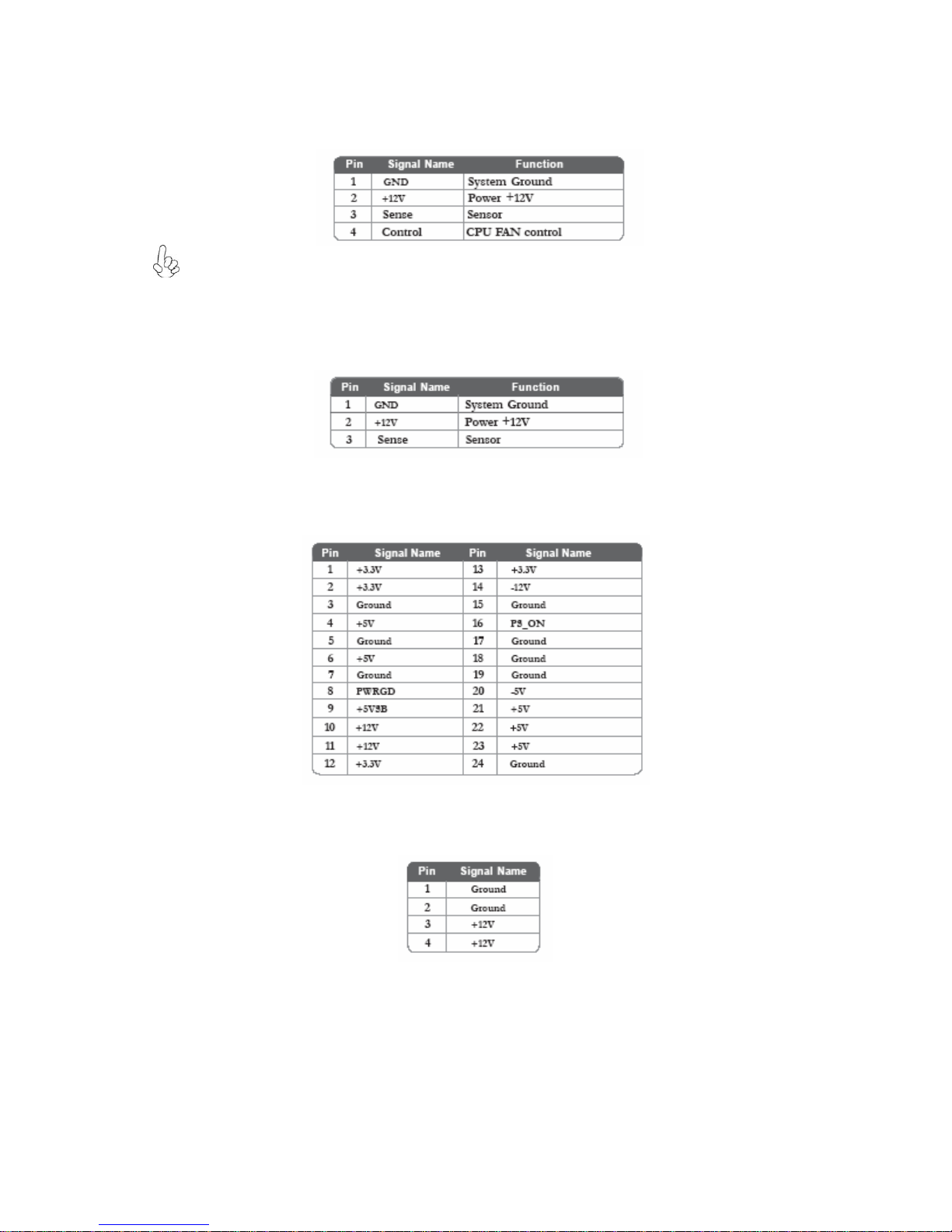
CPU_FAN: CPU cooling FAN Power Connector
Users please note that the fan connector supports the CPU cooling fan of 1.1A ~
2.2A (26.4W max) at +12V.
SYS_FAN/PWR_FAN/NB_FAN: FAN Power Connectors
Pin Signal Name Function
ATX_POWER: ATX 24-pin Power Connector
Pin Signal Name Pin Signal Name
ATX12V: ATX 12V Power Connector
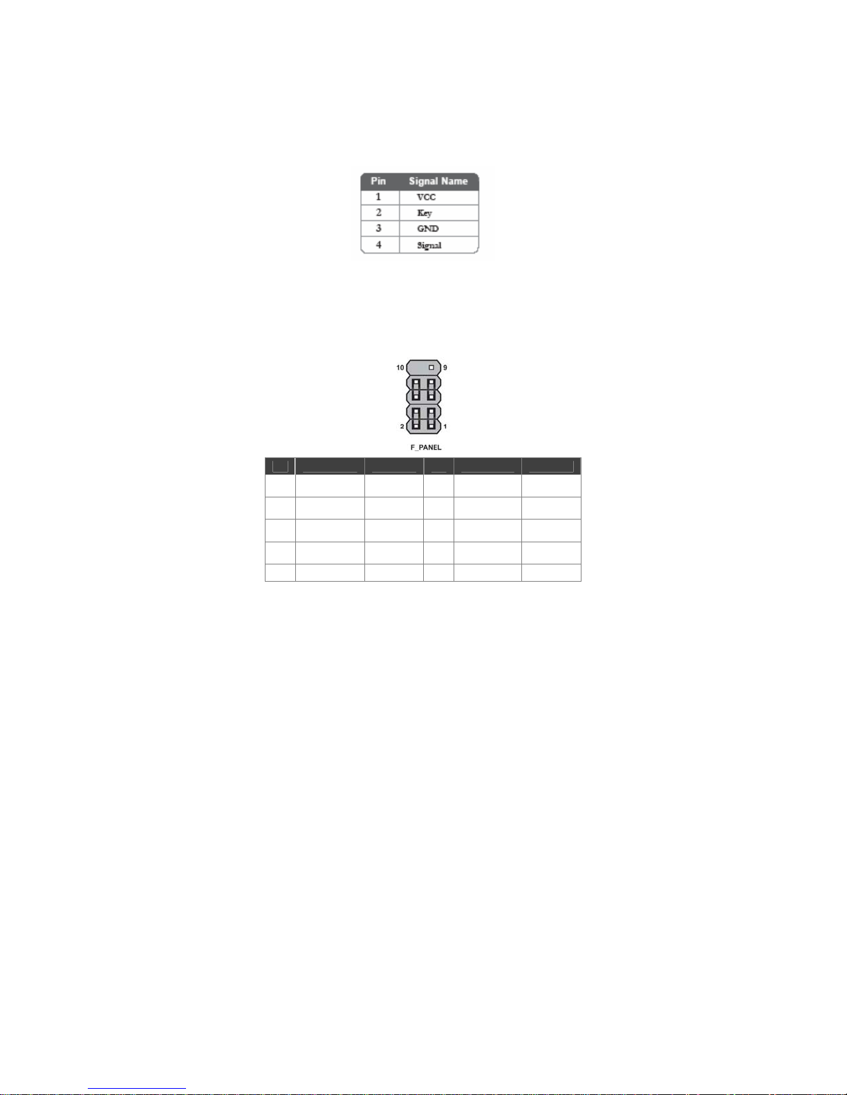
SPK: Internal speaker header
Front Panel Header
The front panel header (F_PANEL) provides a standard set of switch and LED headers commonly found on ATX or Micro ATX cases.
Refer to the table below for information:
Pin Signal Function Pin Signal Function
1 HD_LED_P
3 HD_LED_N
5 RST_SW_N
7 RST_SW_P
9 RSVD Reserved 10 Key No pin
Hard disk
LED (+)
Hard disk
LED (-)
Reset
Switch (-)
Reset
Switch (+)
FP
2
PWR/SLP
FP
4
PWR/SLP
6 PWR_SW_P
8 PWR_SW_N
*MSG
LED (+)
*MSG
LED (-)
Power
Switch (+)
Power
Switch (-)
* MSG LED (dual color or single color)
Hard Drive Activity LED
Connecting pins 1 and 3 to a front panel mounted LED provides visual indication that data is being read from or written to the hard
drive. For the LED to function properly, an IDE drive should be connected to the onboard IDE interface. The LED will also show
activity for devices connected to the SCSI (hard drive activity LED) connector.
Power/Sleep/Message waiting LED
Connecting pins 2 and 4 to a single or dual-color, front panel mounted LED provides power on/off, sleep, and message waiting
indication.
Reset Switch
Supporting the reset function requires connecting pin 5 and 7 to a momentary-contact switch that is normally open. When the switch is
closed, the board resets and runs POST.
Power Switch
Supporting the power on/off function requires connecting pins 6 and 8 to a momen-tary-contact switch that is normally open.
The switch should maintain contact for at least 50 ms to signal the power supply to switch on or off. The time requirement is
due to internal de-bounce circuitry. After receiving a power on/off signal, at least two seconds elapses before the power
supply recognizes another on/off signal.

Installing Hardware
Installing the Processor
Caution: When installing a CPU heatsink and cooling fan make sure that you DO NOT scratch the motherboard or
any of the surface-mount resistors with the clip of the cooling fan. If the clip of the cooling fan scrapes across the
motherboard, you may cause serious damage to the motherboard or its components.
On most motherboards, there are small surface-mount resistors near the processor socket, which may be
damaged if the cooling fan is carelessly installed.
Avoid using cooling fans with sharp edges on the fan casing and the clips. Also, install the cooling fan in a
well-lit work area so that you can clearly see the motherboard and processor socket.
Before installing the Processor
This motherboard automatically determines the CPU clock frequency and system bus frequency for the processor. You may
be able to change these settings by making changes to jumpers on the motherboard, or changing the settings in the system
Setup Utility. We strongly recommend that you do not over-clock processors or other components to run faster than their
rated speed.
Warning: Over-clocking components can adversely affect the reliability of the system and introduce errors into your
system. Over-clocking can permanently damage the motherboard by generating excess heat in components that are run
beyond the rated limits.
This motherboard has a socket AM2+/AM2 processor socket. When choosing a processor, consider the performance
requirements of the system. Performance is based on the processor design, the clock speed and system bus frequency of the
processor, and the quantity of internal cache memory and external cache memory.
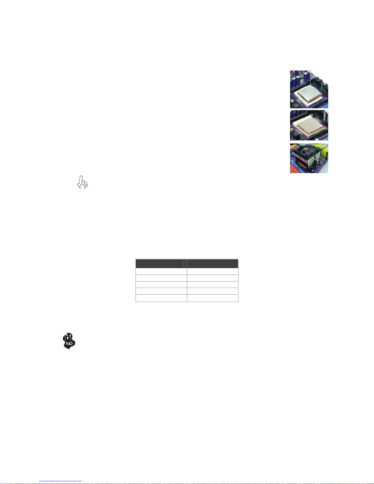
CPU Installation Procedure
The following illustration shows CPU installation components.
1 Unhook the locking lever of the CPU socket. Pull the locking lever away from the socket
and raising it to the upright position.
2 Match the pin1 corner marked as the beveled edge on the CPU with the pin1 corner on
the socket. Insert the CPU into the socket. Do not use force.
3 Push the locking lever down and hook it under the
latch on the edge of socket.
4 Apply thermal grease to the top of the CPU.
5 Install the cooling fan/heatsink unit onto the CPU, and secure them all onto the socket.
6 Plug the CPU fan power cable into the CPU fan connector (CPU_FAN) on the
motherboard.
To achieve better airflow rates and heat dissipation, we suggest that you use a high quality fan with 4800 rpm at least.
CPU fan and heatsink installation procedures may vary with the type of CPU fan/heatsink supplied. The form and size of
fan/heatsink may also vary.
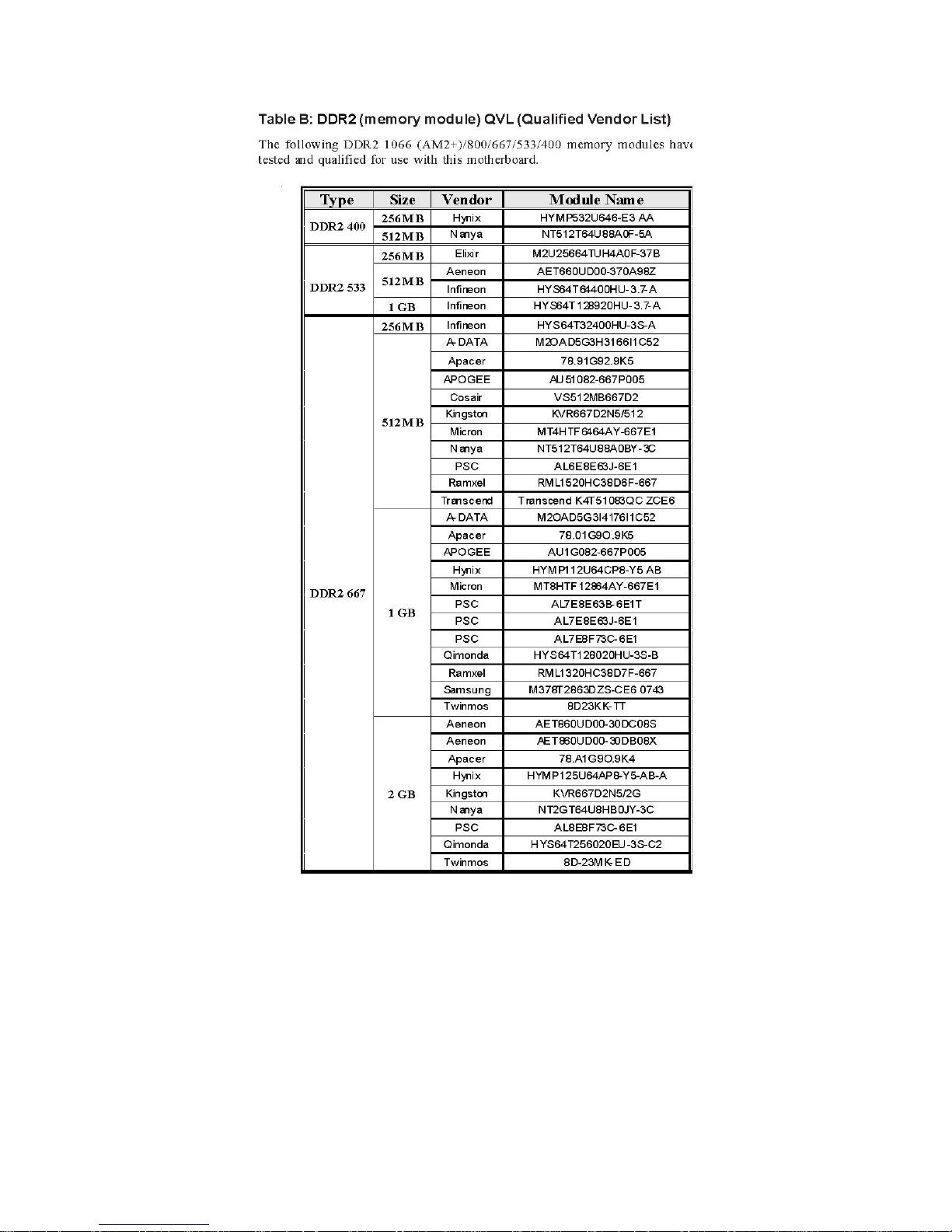
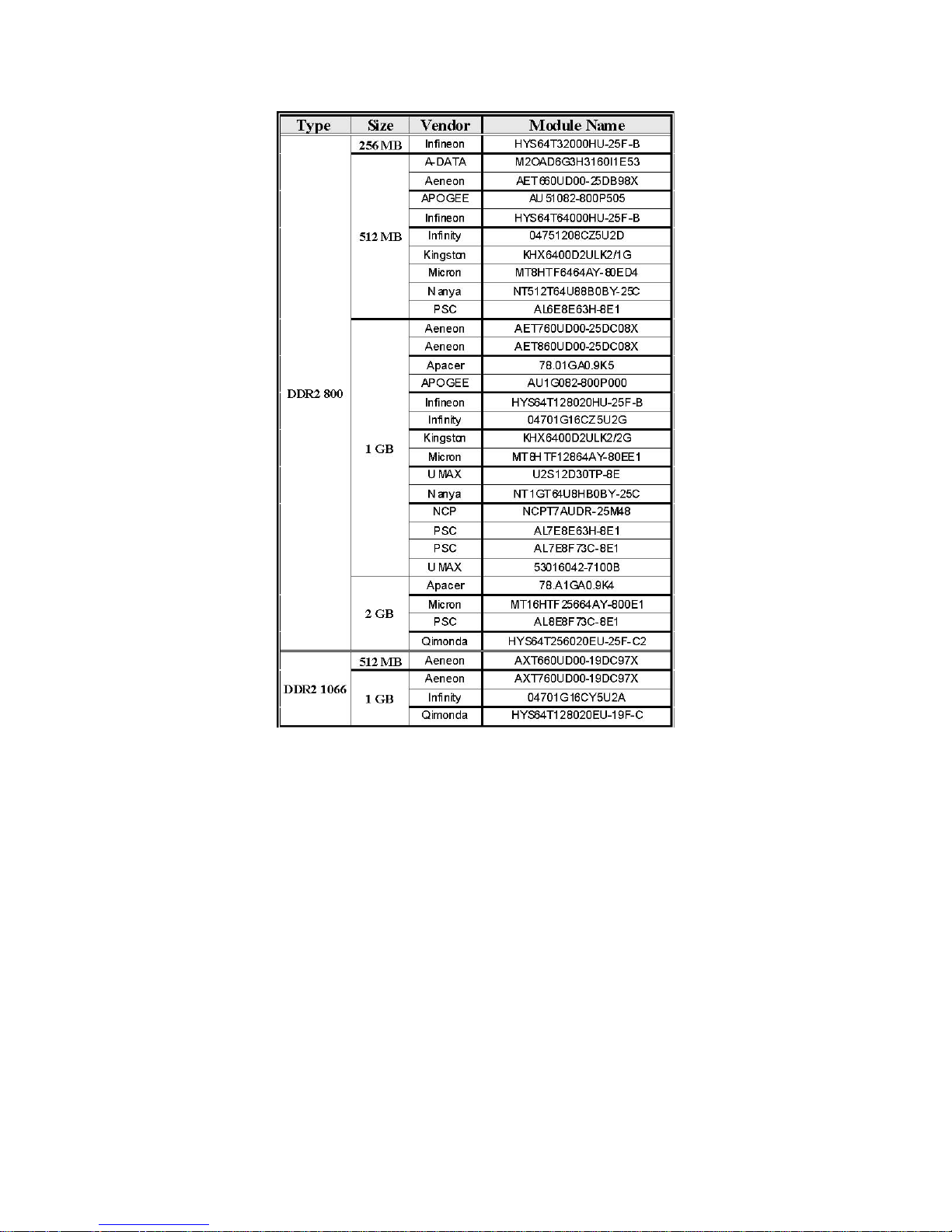
Installing Memory Modules
This motherboard accommodates four memory modules. It can support four 240-pin DDR2 1066 (AM2+)/800/667/533/400.
The total memory capacity is 32 GB*.
DDR2 SDRAM memory module table
Memory module Memory Bus
DDR2 400 200 MHz
DDR2 533 266 MHz
DDR2 667 333 MHz
DDR2 800 400 MHz
DDR2 1066 533 MHz
You must install at least one module in any of the four slots. Each module can be
installed with 8 GB of memory; total memory capacity is 32 GB*.
Do not remove any memory module from its antistatic packaging until you are
ready to install it on the motherboard. Handle the modules only by their edges. Do
not touch the components or metal parts. Always wear a grounding strap when
you handle the modules.
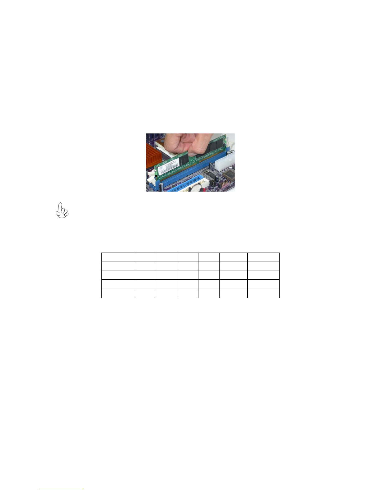
Installation Procedure
Refer to the following to install the memory modules.
1 This motherboard supports unbuffered DDR2 SDRAM only.
2 Push the latches on each side of the DIMM slot down.
3 Align the memory module with the slot. The DIMM slots are keyed with notches and the DIMMs are
keyed with cutouts so that they can only be installed correctly.
4 Check that the cutouts on the DIMM module edge connector match the notches in the DIMM slot.
5 Install the DIMM module into the slot and press it firmly down until it seats correctly. The slot latches
are levered upwards and latch on to the edges of the DIMM.
6 Install any remaining DIMM modules.
For best performance and compatibility, we recommend that users install DIMMs in the sequence of DIMM3,
DIMM4, DIMM1 and DIMM2.
Recommend configuration for best performance and compatibility
Number of
DIMMs
1
2
3 √
4 √ √ √ √
DIMM 1 DIMM 2 DIMM 3 DIMM 4 AM2 AM2+ *
X X
X X
X
√
√ √
√ √
X
Single
Channel
Dual
Channel
Single
Channel
Dual
Channel
Single Mode
Dual Mode
Single Mode
Dual Mode
 Loading...