

Pneutrol International Limited Rapid 600C User Manual

Issue 1.3
1
Rapid 600C
Continuous Mixing Plant
User Manual
Pneutrol International Limited,
5 Caulside Drive,
Antrim,
Co. Antrim,
N. Ireland.
TEL: +44 (0) 28 9448 1800
FAX: +44 (0) 28 9448 1801
03/11/2015

Issue 1.3
2
Contents
1: GENERAL INFORMATION .......................................................................................................... 4
1.1: System Hardware ...................................................................................................................... 4
1.2: System Software Standard Features.......................................................................................... 5
2: SYSTEM SET-UP ........................................................................................................................... 6
2.1: Standard Navigation bar: .......................................................................................................... 7
3: RUNNING INFORMATION: ......................................................................................................... 8
3.1 Running Screen – Manual Controls: ........................................................................................ 10
4: STATISTICS: ................................................................................................................................ 14
4.1: Production Summary: ............................................................................................................. 15
4.2: Stock: ...................................................................................................................................... 17
4.3: Trucks: .................................................................................................................................... 18
4.4: Drivers: ................................................................................................................................... 19
4.5: Delivery Supplier: ................................................................................................................... 20
5: RECIPE SCREEN: ........................................................................................................................ 21
5.1: View/Edit Recipes: ................................................................................................................. 22
5.1.1: Calibrate Recipes: ............................................................................................................ 23
5.2: Recipe Groups:........................................................................................................................ 28
6: CUSTOMERS: .............................................................................................................................. 29
7: SETUP: .......................................................................................................................................... 30
7.1: Plant Setup: ............................................................................................................................. 31
7.1.1: General Variables: ........................................................................................................... 32
7.1.2: Drives: .............................................................................................................................. 33
7.1.3: Times: .............................................................................................................................. 34
7.1.4: Drain Times: .................................................................................................................... 35
7.1.5: Alarm Times: ................................................................................................................... 36
7.1.6: Tolerances: ....................................................................................................................... 37
7.1.7: Rates:................................................................................................................................ 38
7.1.8: Drive Comms Control: ..................................................................................................... 39
7.1.9: Cement Calibration .......................................................................................................... 40
7.2: Material Setup: ........................................................................................................................ 44
7.3: Supplier Setup: ........................................................................................................................ 45
7.4: Moisture Setup: ....................................................................................................................... 46
7.5: Printer Setup: .......................................................................................................................... 48
7.6: IO Status: ................................................................................................................................ 50
7.7: Users: ...................................................................................................................................... 51
8: CHARTS: ....................................................................................................................................... 52
8.1: Historical Chart: ...................................................................................................................... 53
8.2: Real Time Flows Chart: .......................................................................................................... 55
9: MANUALS: ................................................................................................................................... 57
10: BACKUP DATABASE: .............................................................................................................. 58
11: REMOTE LAPTOP ..................................................................................................................... 59
11.1: Remote Viewing on Laptop: ................................................................................................. 60
11.2: Laptop Assuming Main Control of Plant: ............................................................................. 61
12: DIAGNOSTICS/ALARMS: ........................................................................................................ 64
12.1: Alarms Screen: ...................................................................................................................... 64
13: REMOTE ACCESS: .................................................................................................................... 65
13.1: Modifying Network Providers’ APN Settings: ..................................................................... 67
14: SHUTDOWN SYSTEM: ............................................................................................................. 69
15: USEFUL INFORMATION: ........................................................................................................ 69
15.1: Pausing The System: ............................................................................................................. 69
15.2: Emergency Stop: ................................................................................................................... 70
15.3: Safety Pull Switches ............................................................................................................. 71

Issue 1.3
3
15.4: Mixer Castell Interlocking System ....................................................................................... 73
15.5: How To Reset VSD’s ............................................................................................................ 75
15.6: Compressor ........................................................................................................................... 76
15.7: Pneumatic Valve Box Lubricators/Air Pressure Setup ......................................................... 78
15.8: HMI ....................................................................................................................................... 79
15.9: How to Calibrate Moisture Probes ........................................................................................ 80
15.10: Admix Dispenser ................................................................................................................ 82
15.11: Hydraulic Controls .............................................................................................................. 83
15.12: What to Do If You Have a Problem? .................................................................................. 84
16: APPENDIX 1 – Best Practice/Regular Checks ........................................................................... 85
17: APPENDIX 2 – Full Alarm List .................................................................................................. 86
18: APPENDIX 3 – Troubleshooting Guide...................................................................................... 90

Issue 1.3
4
1: GENERAL INFORMATION
The Control System and Software have been designed and developed specifically for the control of
Concrete Batching Plants. The Hardware that is housed inside our Control Panel has been chosen
for its reliability in operation and for flexibility in different applications.
The software is 'Customised' for each plant and is therefore suitable for all types of plants and
plant layouts.
1.1: System Hardware
CONTROLLER: - ALLEN BRADLEY Micrologix Processor.
- Uses Industry Standard Ladder Logic Programs.
- CSA Certification to Class 1 Division 2.
- Battery-backed up memory for protection of program and data.
- Can be expanded to take in 256 additional discrete I/O
- Built-in LCD with backlight allows you to view controller and I/O status
TERMINAL: - Exor eTOP 15” touch screen operator interface
- 16.2M colours, providing XGA 1024x768resolution display
- Energy efficient LED display
- Displays all plant data.
- Displays plant operation on screen.
PRINTER: - Able Systems Ltd Ap1400V Thermal Panel Printer
- Robust design with added protection for harsh environments
- Mechanism life of 13 million print lines
- Print speed of 80mm/sec
- Flexible connectivity

Issue 1.3
5
1.2: System Software Standard Features
1. STORAGE OF RECIPES: Each recipe will contain the details regarding a specific blend of
materials, which is the amount of each of the aggregates, cement, water and additives if required.
There is no limit to the number of recipes the system can store.
2. PASSWORD PROTECTION: Information in the memory of the computer can be protected by a
password code to prevent any unauthorised person deleting, changing or resetting stored data.
3. STOCK CONTROL: Materials in stock and material usage are stored in memory on the HMI.
These may be displayed as required to give daily or monthly totals for each material used in the
plant and stock levels remaining.
4. NO FEED: Should a bin be empty or material be bridged in the bin then an alarm message will
be given.
5. PRINTER: The system printer is used to print a ticket on demand or automatically given the
parameters input for print detail.
6. PLANT ALARMS: An alarm message will be placed in an alarm log and displayed on the
monitor. A printout will be given of any/all alarm faults together with a date and time.
Alarm messages are given for specific faults e.g.
‘Mixer not running’
The operator may therefore rectify the problem quickly and so save on plant 'Down Time'.
An audible and/or visual alarm is also available where the operator may be a considerable
distance from the Control Panel.
Once the alarm has been initiated the operator may push the alarm accept button at the control
panel once to cancel the audible/visual alarm. He must then push the alarm accept button again
to continue batching once the fault has been rectified. Also the operator may rectify an alarm
when in the alarm screen using option "F1: ACCEPT ALARMS".
7. MONITOR:
Displays Selection Menus.
Displays recipes
Displays mix tolerances
Displays alarms
Displays plant Inputs and Outputs.
Displays running screen.
Displays a variety of stock and production reports
Displays customer information

Issue 1.3
6
2: SYSTEM SET-UP
When the generator is started, the UPS and HMI will automatically be turned on. During the
course of normal use, if the HMI is not being used, it will automatically go into sleep mode. There
is a small LED in the top right hand side of the HMI which alerts the user to the following:
Red – Power is on, but the HMI is turned off
Amber – Power is on, but the HMI is in sleep mode
Green – Power is on and the HMI is on
When the HMI is powered on, the following Log On screen will appear:
Enter user name and password to log onto the system. This will launch the running screen of the
continuous mixing plant and highlight the following as sown below in the figure:
Conveyor status
Mixer status
Drive speed
Material loads across the system
Tons per hour target
Issue 1.3
7
2.1: Standard Navigation bar:
The navigation bar (shown above) appears at the top of all screens in the system except for the
reports screens.
View Alarms. In order to view alarms, hold down the ‘alt’ key and press 1.
View Running Screen. In order to view the running screen, hold down the ‘alt’ key and
press 2.
View Silo Screen. In order to view the silo control, hold down the ‘alt’ key and press 3.
View Recipes. In order to view the recipes, hold down the ‘alt’ key and press 4.
View Plant Setup. In order to view system setup, hold down the ‘alt’ key and press 5.
You also can enter any of the navigation bars by just touching them on touch screen or by
left clicking the mouse over them.

Issue 1.3
8
3: RUNNING INFORMATION:
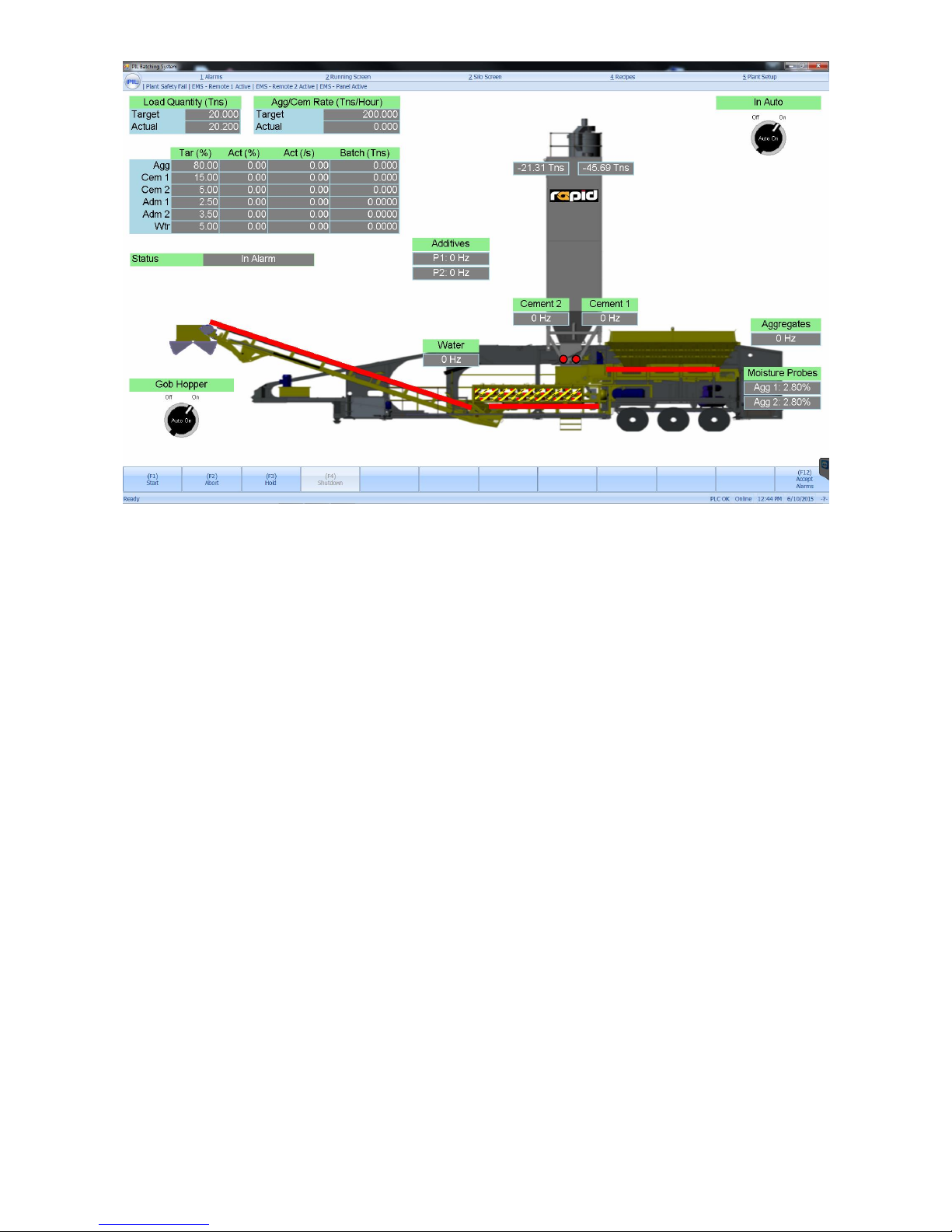
After the HMI is powered up, the running screen is the default, home screen, which allows the
operator to oversee the entire continuous mixing process.
The Auto/Manual selector switch in the top right of the screen, lets the user know which control
mode the plant is currently in.
A graphical representation of the plant is shown in the running screen. The running screen has
weight indicator boxes around the weigh hoppers which show the actual weight in each hopper.
The current live drive speeds are also shown.
In the top left hand corner of the running screen the following information is displayed:
Load Qty (Tns) – actual batched quantity versus the target
Agg/Cem Qty Rate (Tns/Hour) – actual quantity rate in tons per hour versus the target rate
Target % - Percentage of each material being used in the current recipe. Calculated from the load
quantity and target tons per hour rate.
Actual % - Percentage of each material being used in the current recipe, calculated from the
amount of material leaving the hoppers and feeders (continuously updated.)
Actual Kgs or Lbs/s – Displays the actual flow rate per second of each material
Batched (Tns) – Displays how many ton of material have been utilized
Water Adjust % – this allows the user to change the water target percentage in real time.
To the bottom left of the Running Screen the Start, Abort, Hold and Shutdown buttons are
displayed.
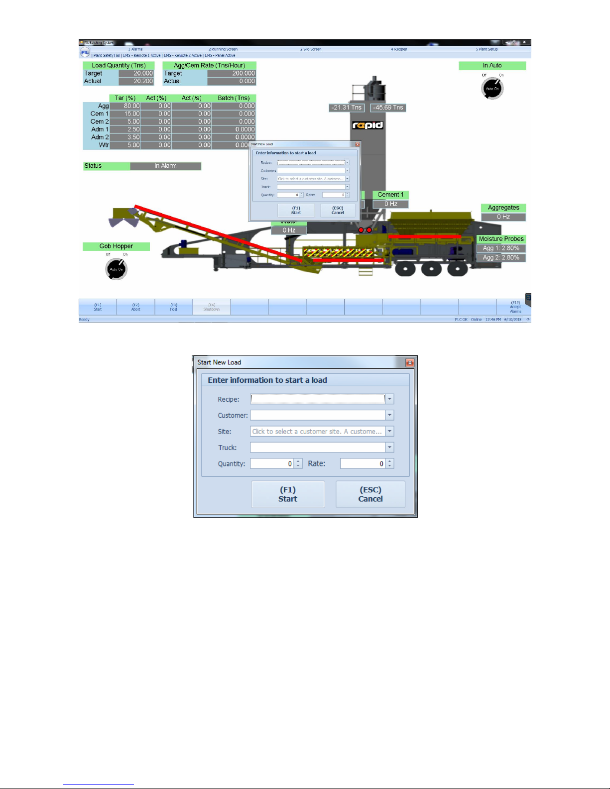
When the Start button is pressed, a dialogue box as shown below pops up on screen:
Issue 1.3
9
A close up of this dialogue box is shown below:
The user can select the recipe, customer, site and truck using the drop down menus. After
selecting these 4 options the user enters the quantity to be batched and the batching rate (in tons
per hour). We will look at how recipes, customer information, site details and truck information
are entered later in this manual. After a load has been completed, the same details will
automatically appear in the start dialogue box. Al the user will need to do is press “Start”.
Issue 1.3
10
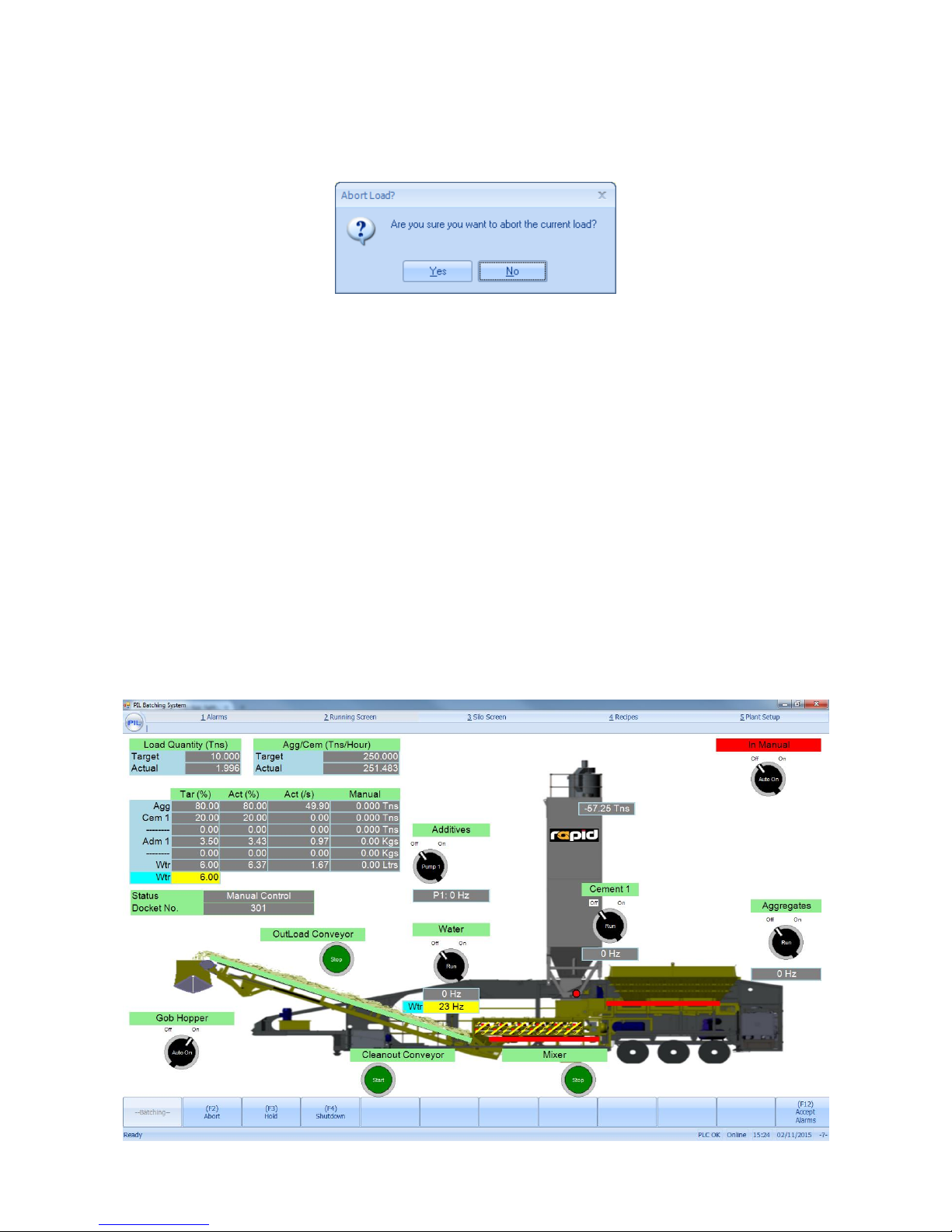
The second button along the bottom of the screen is the Abort button. When this button is
pressed, the system immediately stops what it is doing and resets its automatic program – any
material already weighed up will have to be discharged from the system manually by the operator.
This buttons function is primarily used to reset the program, but in case of emergency if the
wrong mix has been setup or started, this button can be used to minimise the amount of material
produced in error.
Beside Abort is the Hold button, this button does exactly what it says, when this button is
pressed the entire plant will pause what it is doing and wait until its pressed again to taken off
hold. The mixer and outloading conveyor will continue to run, but the aggregate belts feeding the
mixer and also the cement filling/emptying process will pause. A large, red ‘HOLD’ warning
appears below auto/manual toggle switch on the running screen.
The last button in this row is the Shutdown button, this button is used to shutdown the plant
when in the middle of a production run. For example, if the user has started the plant off making
25 tons of material, the shutdown button can be pressed at anytime, this will ensure the plant
stops producing any further material and shuts the system down in an orderly fashion as it would
do if it had reached its 25 ton target, ensuring the outfeed belt and mixer are totally drained out
and empty of material.
3.1 Running Screen – Manual Controls:
At any point the user can chose to turn the plant into manual control as shown below by selecting
the auto/manual switch in the top right corner:

Issue 1.3
11
When in manual mode, as you can see from the screenshot above, manual control buttons appear
beside every device that can be controlled. These manual controls are very user friendly and very
intuitive. Each belt can be started and stopped using the green pushbuttons, there are
pushbuttons to fill and run the cement weigh hoppers and to open and close doors. The second
type fo buttons used are 2 position selector switches – these can be toggled from left to right and
are generally used for switching processes on and off. As the screenshot above demonstrates additives, water, cement, aggregates and the gob hopper control can be turned off and on.
The Gob Hopper has its own unique auto/manual control sequence. In the bottom left of the
mimic screen, there is a Gob Hopper Auto On. When this button is turned onto the ‘On’ position,
the gob hopper door will operate as per the times configued in the plant setup (where there are
gob hopper open and gob hopper closed times). At the end of an automatic batch, the gob hopper
doors will always remain open. When the Gob Hopper auto/manual selector switch is turned to
manual, 2 new push buttons will appear, one for open gob hopper, one for close gob hopper –
these buttons allow the operator to control the gob hopper door completely manually.
There is also the ability to adjust the speed in Hertz of the water VSD from the manual control
screen. The yellow box can be clicked on and the desired new sped in Hertz can be typed in.
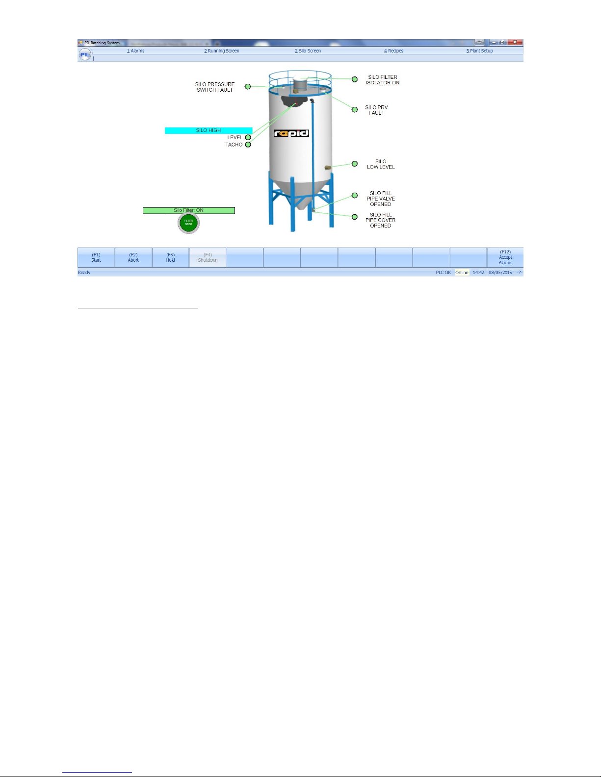
There is an additional button at the top called Silo Screen, pressing this button reveals the screen
shown below:
The silo controls screen provides the user with buttons to control silo filling operations.
Indicators and input buttons are provided to test the silo controls and to start the silo filter as
shown above. There are various indicator boxes around the silo which can give the user its
status, such as fill pipe valve closed or fill pipe valve open, silo low level, silo pressure switch
fault, silo PRV fault, silo filter islolator on and silo high level and tacho feedback (if applicable). If
any component is green, it indicates that item is healthy, however, if something is red, it
highlights there is a fault with this piece of equipment.
Issue 1.3
12
Silo Operating Procedure
1) To activate the system, the operator must press the lamp test button, which will activate
the system fault neon’s and the beacon / klaxon. When the operator has checked the fault
lights and beacon / klaxon are operating correctly he/she can press the filter start button.
If the filter start button is not pressed within 15 minutes of the lamp test button being
pressed the system will reset and the lamp test will have to be pressed before the filter can
be started.
2) When the filter start button is pressed the Safe-silo system checks all of the safety sensor
inputs to ensure everything is healthy before opening the fill pipe valve and starting the
silo filter. When the system is operating, the filter start pushbutton will be change to
‘Filter Stop’
3) If a high level is reached, the warning beacon / klaxon will energise to alert the truck
driver to stop filling, the indicator neon on the mimic will illuminate red and the fill pipe
valve will close after 45 seconds. When the fill pipe closes after a high level it will not open
again until the high level signal has been removed. The red neon will remain illuminated
until the high level signal has been removed. The alarm beacon / klaxon can be cancelled
at any time by pressing the alarm cancel button.
If any of the following faults occur the fill pipe valve will close immediately and the alarm
beacon / klaxon will energise:
If the High Level fail safe signal is lost (also known as the Tacho signal)
If the Pressure Switch sensor activates
If any faults occur the status neon will illuminate red and remain energised until the
alarm cancel button is pressed.
If a high level fail safe fault has been installed and a fault occurs, the tacho neon will flash
red for 45 seconds unless the alarm cancel is pressed. Then once the lamp test button is
pressed the alarm light will re-energize.
4) When the truck driver has finished discharging into the silo he should press the ‘Filter
Stop’ button which will close the silo fill pipe valve and allow the filter to remain cleaning
for 10 minutes. If the stop button is not pressed the system will automatically shut down
after 45 minutes.

Issue 1.3
13
Immediate System Shutdown
The rotating paddle high level probes have a motor driven paddle extended into the silo. The
paddle shaft is fitted with a motion detector.
When the paddle comes into contact with the cement and stops turning, the motor tries to turn
against the paddle, activating a clutch fitted with monitoring switches to give a high level alarm
signal.
If the rotating paddle high level has a fail safe indicator fitted, when the coupling from the motor
to the paddle shaft becomes disengaged the motion detector will indicate that the motor is turning
and the paddle is not. The high level fail safe alarm will come on immediately and the system will
shut down.
If the filter is blocked, the silo will over pressurize and the pressure switch will activate causing
the system to immediately shut down.
Issue 1.3
14
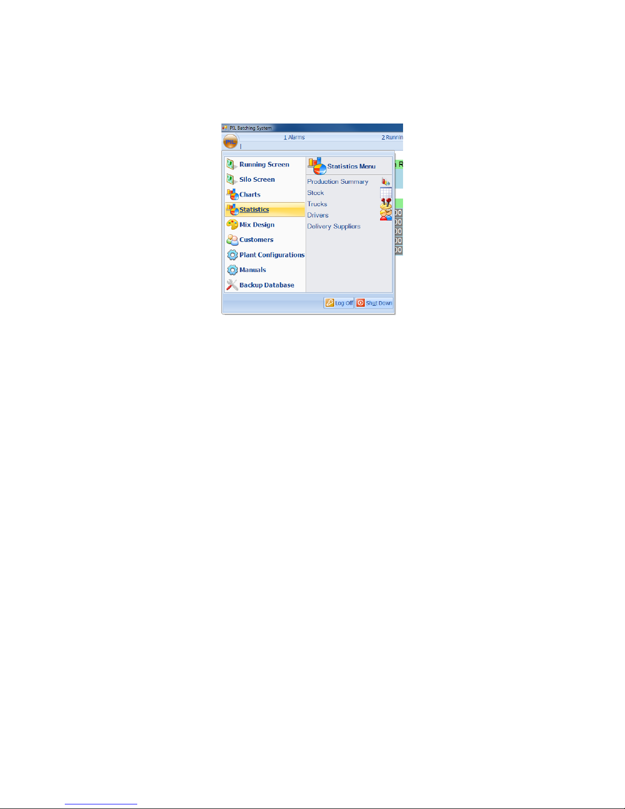
4: STATISTICS:
From the main menu, move the mouse over ‘Statistics’ to see the plant statistics menu. The
system has reporting mechanisms for information relevant to the plant, such as the daily
production screen, a full stock inventory, a record of stock accuracy and docket printing. The
operator can choose what data is required to be reported.
From here, we are given options to view the following plant statistics:
Production Summary
Stock
Trucks
Drivers
Delivery Suppliers
Issue 1.3
15
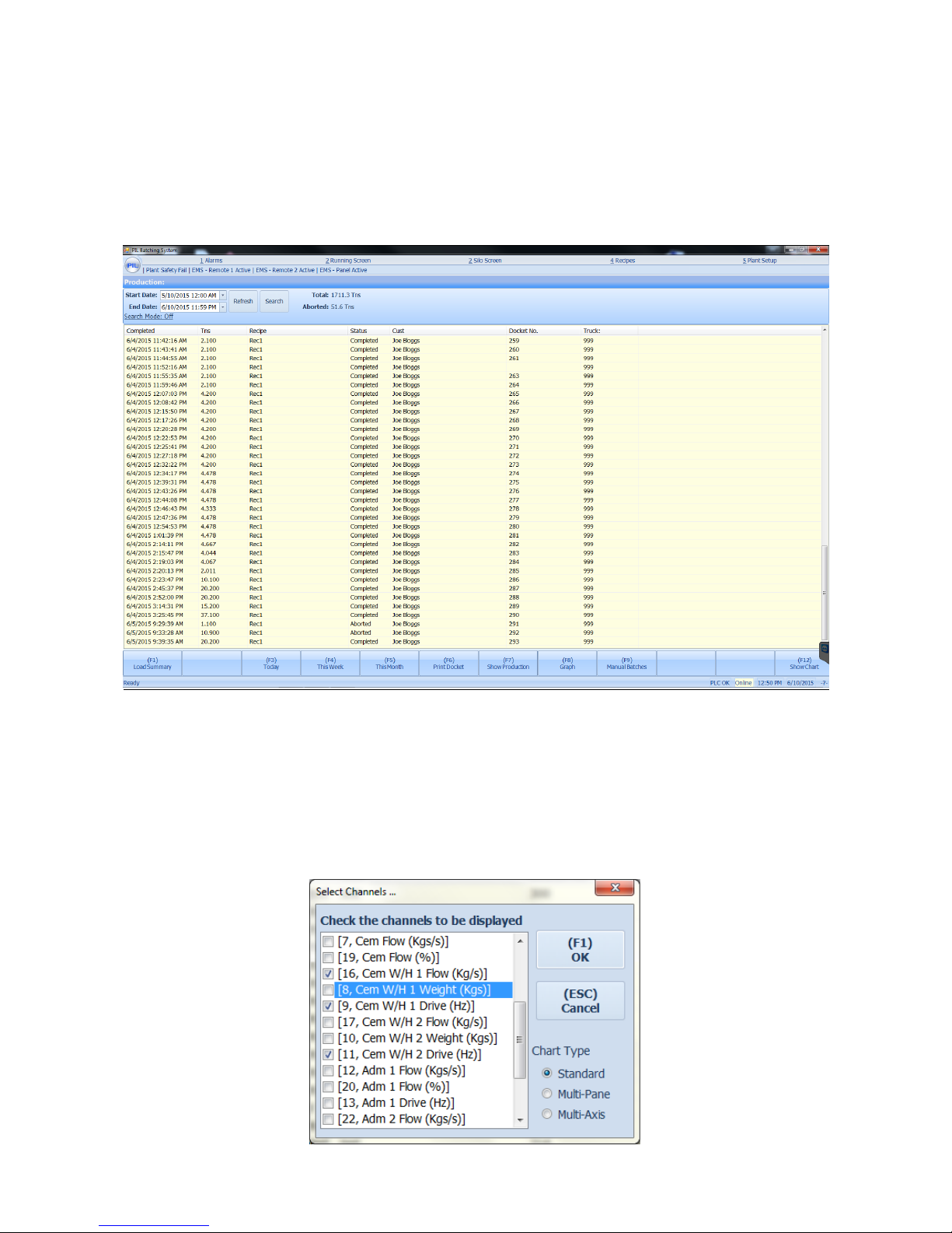
4.1: Production Summary:
From the statistics menu, select ‘Production Summary’ to view the batching history. From here
the operator can view all load details between the dates selected at the top of the screen. Press the
‘tab’ key to highlight the start date. Then use the up, down, left and right arrow keys to change
the date. Press the tab key again to move to the end date and repeat the process. Pressing the
‘tab’ key again will highlight the production list. Then Use the up and down arrows to select the
different drops within the list.
The operator can then view information about each load by selecting it in the list. He/she will
have the option of Viewing a summary of that load (F1), or viewing a drop report for that load (F2).
Pressing ‘F3’ automatically sets the dates to show only today’s production. Pressing ‘F4’ sets the
dates to show production since the beginning of the week (Sunday). Pressing ‘F5’ sets the dates to
show production since the beginning of the month. The operator can also print a docket for that
load if necessary (F6). A production report can be printed by pressing ‘F7’. Pressing ‘F8’ will show
a bar graph for the production. Pressing ‘F9’ will prompt you to select the dates which you want to
view any manual batches recorded. The operator also has an (F12) option which allows the user
to look back at historical charts and trending for loads previously completed. When this button is
selected, the following dialogue box appears:
Issue 1.3
16
The user is provided with the option to select the particular weighers or flow rates they require to
view on the chart. For more information on charts, please see section 8.
The operator can view all the loads completed for a certain customer or truck by pressing the tab
button to highlight the ‘Customer’ or ‘Truck’ and pressing the up and down arrow to select the
customer or truck number.
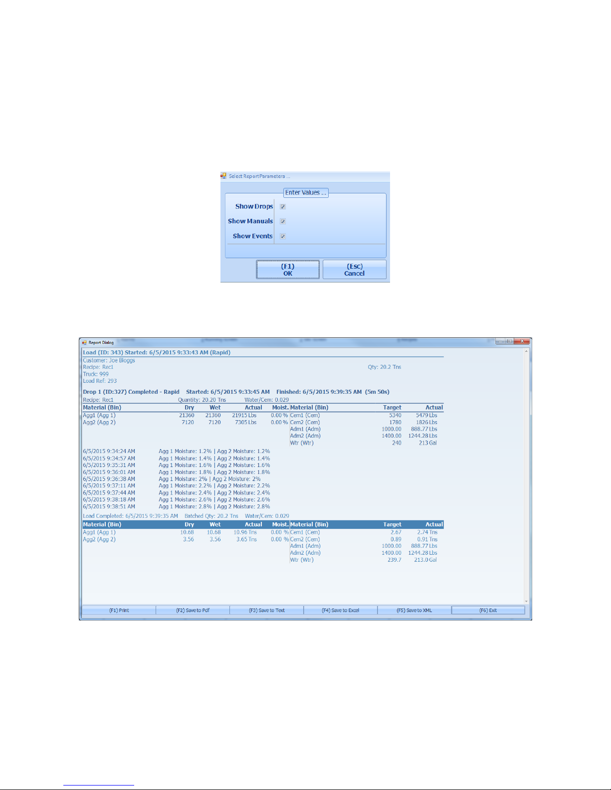
When options (F1) or (F2) are selected, the user will be asked whether or not they want to view
any events, drops or manual controls that occurred during that load in the report. This is selected
by default. The appropriate report will then be shown, along with the standard report options.
The appropriate production report will then be shown, along with the standard report options as
shown below:
Issue 1.3
17
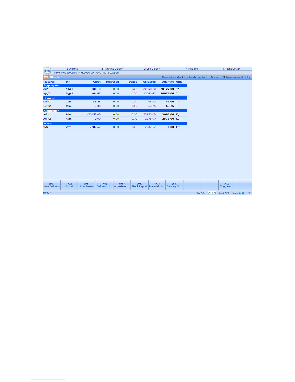
4.2: Stock:
From the statistics menu, select ‘Stock Screen’ to view the stock screen. The stock screen allows
the operator to keep track of stock levels within the plant and modify if necessary. Use the arrow
keys to select the date for which you want to view stock. This will automatically open today’s date
by default.
For any given day, selected at the top of the screen, the operator can view the amount of each
material present in stock at the start of the day (‘Open’), any deliveries for that day (‘Delivered’),
stock usage for that day (‘Usage’), any stock adjustments made (‘Adjusted’) and the actual current
stock quantity (‘Quantity’).
This screen gives the operator the options to:
Make a new delivery (F1)
Make a stock adjustment (F2)
Set low levels for each Bin [F3] – option at top of screen to set alarm when stock low levels
reached.
View a report on the history of deliveries(F4)
View a report on the history of adjustments (F5)
View the stock report (F6)
View the material usage (F7)
Toggle Admixture Units between KG’s/Ltrs (F11)
By pressing ‘F1’ to make a new delivery, the ‘Delivery Details’ column will appear on the right
hand side of the screen. Use the up/down arrow keys to select a supplier, or just type in the name
of a new supplier. Use the ‘tab’ key to move onto the delivery date and change if necessary (Using
arrow keys). Again use the ‘tab’ key to move onto the docket number field and type in a docket
number for the delivery. Then enter any notes deemed appropriate. Then use the ‘tab’ key to move
down through the material delivery units and adjust as appropriate. Press ‘F1’ to confirm the
delivery, or ‘F2’ to cancel and undo any changes.
Pressing ‘F2’ to adjust stock levels works similarly. Use the ‘tab’ key to move down through the
quantity units for each material and adjust as appropriate. Press ‘F1’ to confirm the adjustment,
or ‘F2’ to cancel and undo any changes.
Issue 1.3
18
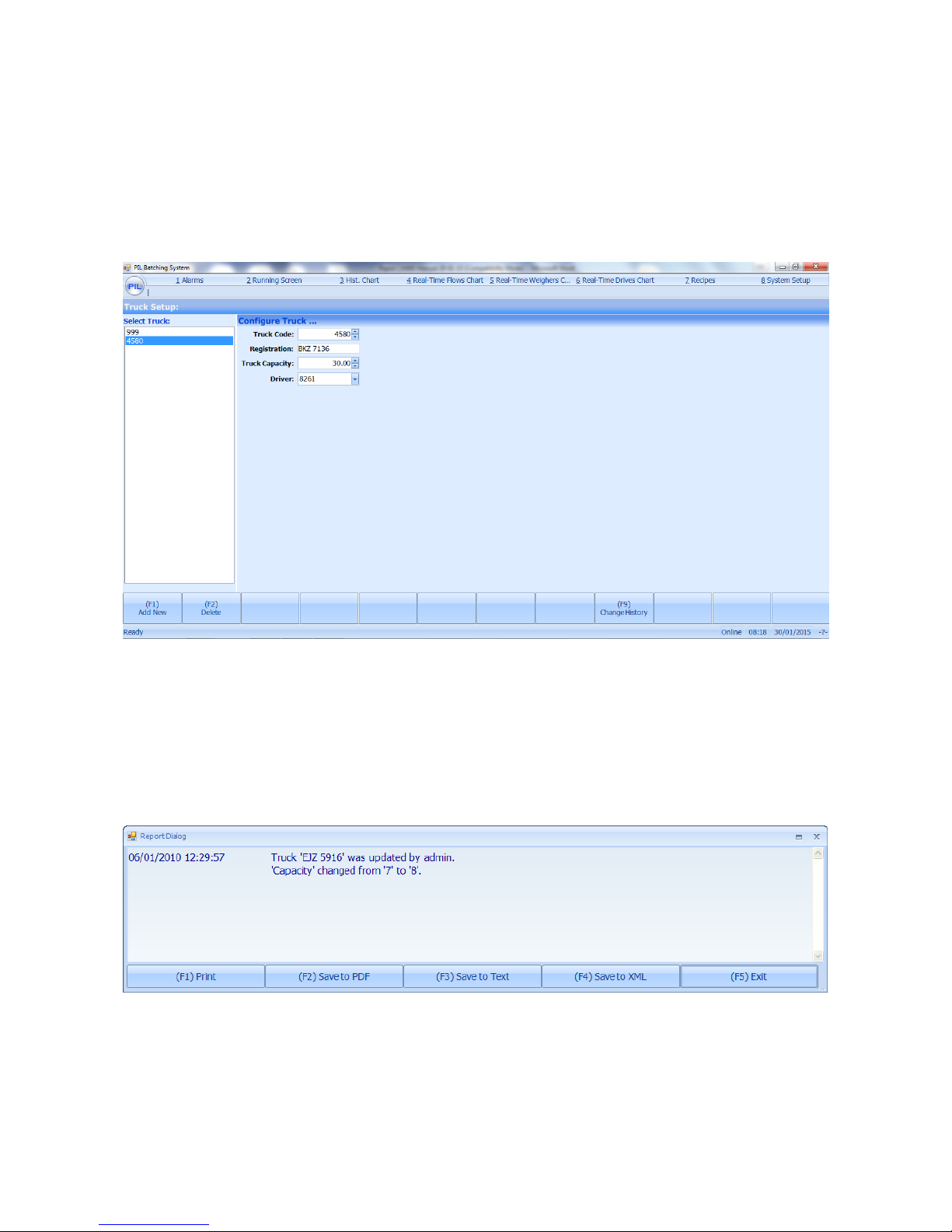
4.3: Trucks:
From the statistics menu, press ‘F5’ to view truck statistics. This screen allows the opera tor to set
up the plants fleet.
Use the up/down arrow keys to move through the list of existing trucks. Use the ‘tab’ key to move
through the truck details for any particular truck. Any changes which are made, pressing ‘F1’ will
save these changes. ‘F2’ will undo the changes.
The operator can add a new truck by pressing the ‘F1’ key. If this is selected, use the tab key to
move to each of the ‘Code’, ‘Registration’ ,‘Truck Capacity’ and ‘Drivers’ fields and enter
appropriate details. The changes can then be saved (F1) or undo (F2).
To delete a truck, select one in the list and press ‘F2’.
Press ‘F9’ to view any changes made to the truck details between the two selected dates. Any
changes which have been made can be Printed (F1) or Saved to a file.

Issue 1.3
19
4.4: Drivers:
From the statistics menu, select ‘Drivers’ to view details of all drivers.
The operator can add a new truck by pressing the ‘F1’ key. If this is selected, use the tab key to
move the ‘Driver Code’ and ‘Name’ fields and enter appropriate details. The changes can then be
saved (F1) or undo (F2).
To delete a driver, select one in the list and press ‘F2’.
Again by pressing ‘F9’ to view any changes made to the driver details between the two selected
dates. Any changes which have been made can be Printed (F1) or Saved to a file.

Issue 1.3
20
4.5: Delivery Supplier:
From the statistics menu, select ‘Delivery Supplier’ to view details of all suppliers.
The operator can add a new supplier by pressing the ‘F1’ key. If this is selected, use the tab key to
move to the ‘Name’ or ‘Short Name’ fields and enter appropriate details. The changes can then be
saved (F1) or discarded (F2).
To delete a supplier, select one in the list and press ‘F2’.
Again by pressing ‘F9’ to view any changes made to the Delivery Supplier details between the two
selected dates. Any changes which have been made can be Printed (F1) or Saved to a file.
Issue 1.3
21
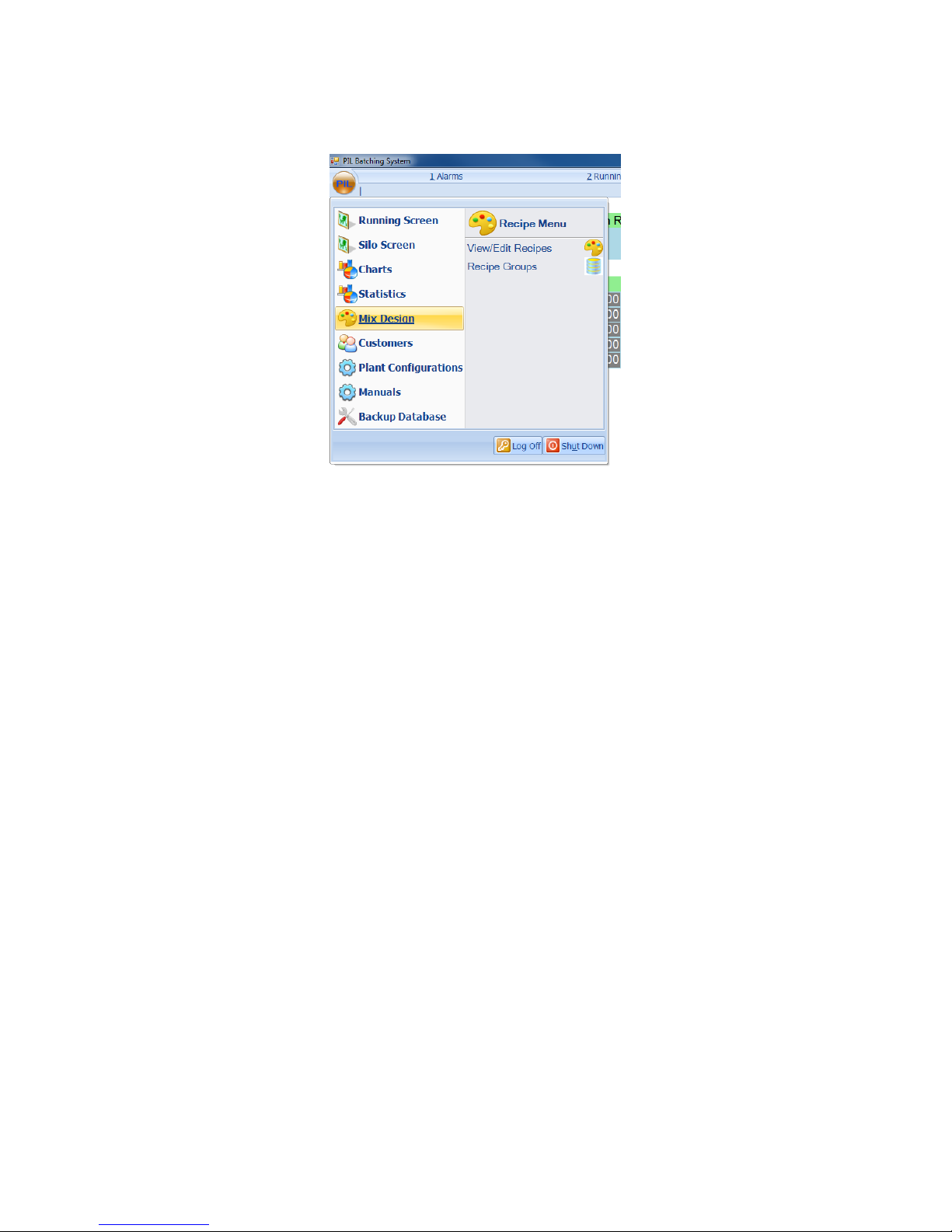
5: RECIPE SCREEN:
From the main menu, select Mix Design to view the recipe menu screen.
This gives us the following options:
View/Edit Recipes
Recipe Groups
Issue 1.3
22
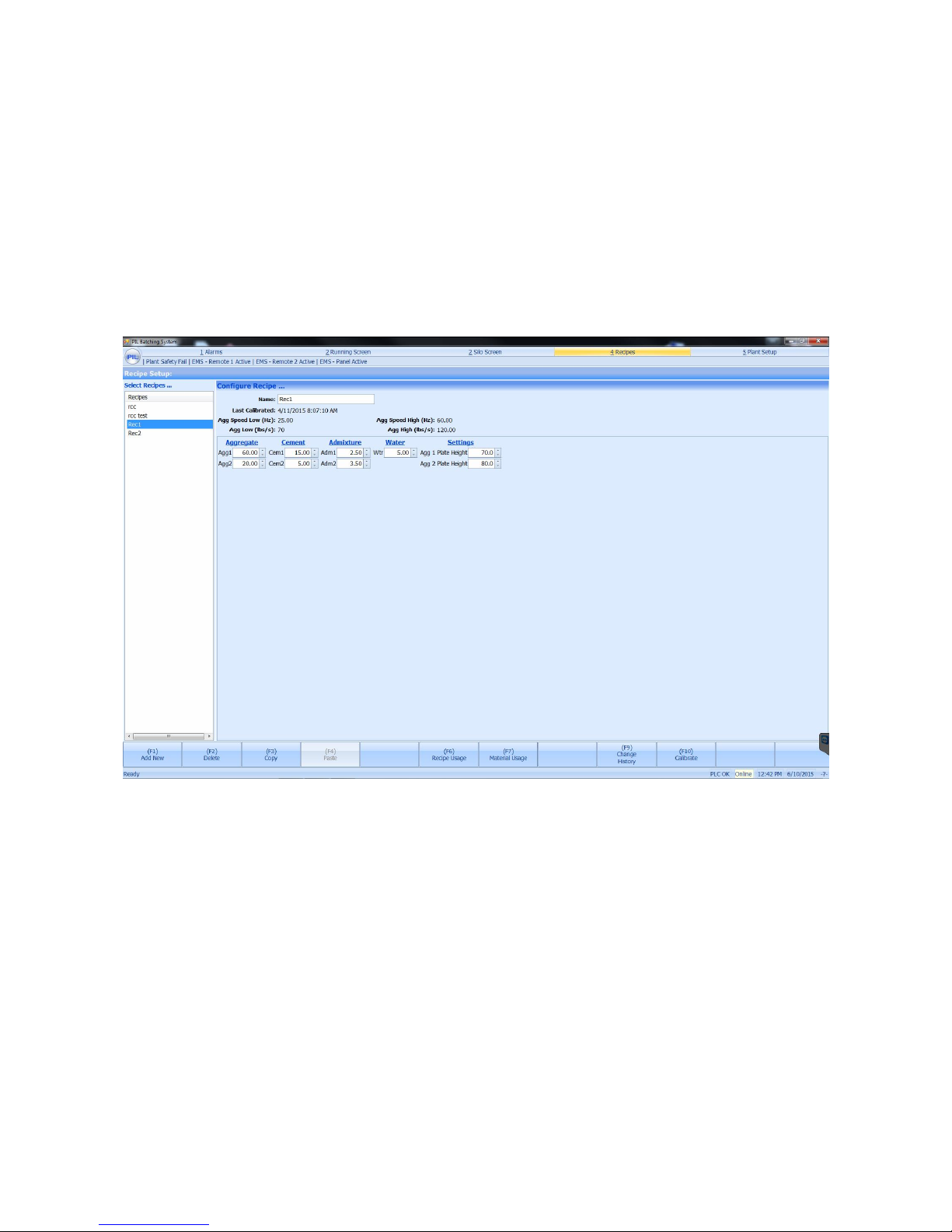
5.1: View/Edit Recipes:
From the recipes menu, select ‘View/Edit Recipes’. This screen allows the operator to configure
all recipes for the plant. Features include:
Virtually unlimited recipes.
Recipe configurable aggregate bin hole settings.
Recipe configurable cleanout belt setting. (when ticked this will run cleanout belt during
production)
Recipe usage report
Material usage report by recipe or selection of recipes
Ability to view change history
Down the left of the screen, there is a list of all existing recipes. These can be easily edited by
selecting one using the up/down arrows as normal, then using the tab key to move through all
the properties which make up the recipe. Each can be edited, and if any changes are made, the
user will be presented with the options of saving (F1) or undoing the changes (F2).
If a new recipe is required, enter the screen and press ‘F1’ to Add New. Select the recipe section
which the new recipe is to be created under and press ‘F1’. The ‘Name’ field will be highlighted.
Enter a name and use the ‘tab’ key to move on to the next field. Once all values have been
entered, press ‘F1’ to save, or ‘F2’ to undo the changes. Recipes can also be deleted, by selecting a
recipe from the existing list on the left of the screen and pressing ‘F2’.
Some recipe statistics are also available, such as a record of all changes made to a recipe (F9), a
summary of recipe usage (F6) and a material usage report (F7), configurable by selecting one or
any number of recipes to be reported on. These reports will appear in the usual format.
Note: If these buttons are grayed out, the current user may not have the rights to access these
features.
Issue 1.3
23
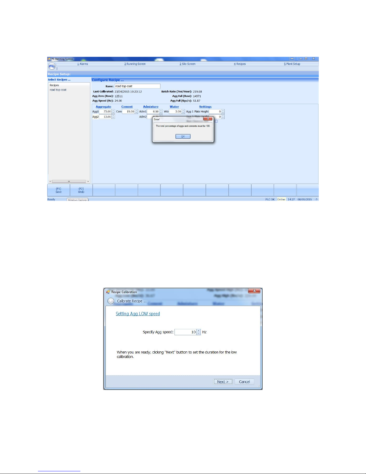
In addition, there are also built in checks to ensure mistakes are not made, for example, when
entering in a recipe, the total aggregate and cement percentages must add up to 100%, otherwise
an error message will be displayed when the user has tried to save the recipe:
5.1.1: Calibrate Recipes:
At the bottom of each recipe there is a calibration button, this allows the user to enter a new
calibration for the aggregate of that recipe. Before any new calibration is considered, the user
must physically check around any weight scales or belts. They must also be sure to charge the
mixer with an appropriate amount of material so that calibration material isn’t filling the mixer
and throwing off calibration numbers! For more info see Appendix 3. When the calibration
button is selected, the following screen appears:
The user is asked to specify the aggregate low running speed. Normally this is set to 10 Hertz,
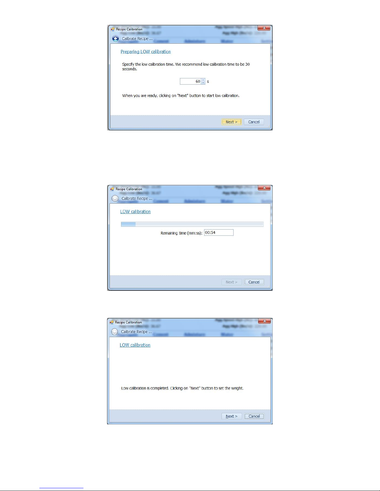
when ‘Next’ is clicked on, a dialogue box appears for setting the Low calibration time:
Issue 1.3
24
The user is asked to specify the aggregate low calibration time. Normally this is set to 120
seconds, when ‘Next’ is clicked on, the mixer and belts will start, allowing the system to run
aggregate through the system on the appropriate gate setting for this period of time - it is
important the user has a truck below the end of the belt, as the amount of material run through
the plant must be weighed after the low calibration has finished. As the low calibration time is
running, you will see the following dialogue box:
The countdown timer allows the user to clearly see how long is left to run on the low calibration
time. After the low calibration time has completed, the following dialogue box will appear:
The system displays confirmation that the low aggregate calibration has been completed. After
the “Next” button is selected, the finish low calibration screen appears as below:
Issue 1.3
25
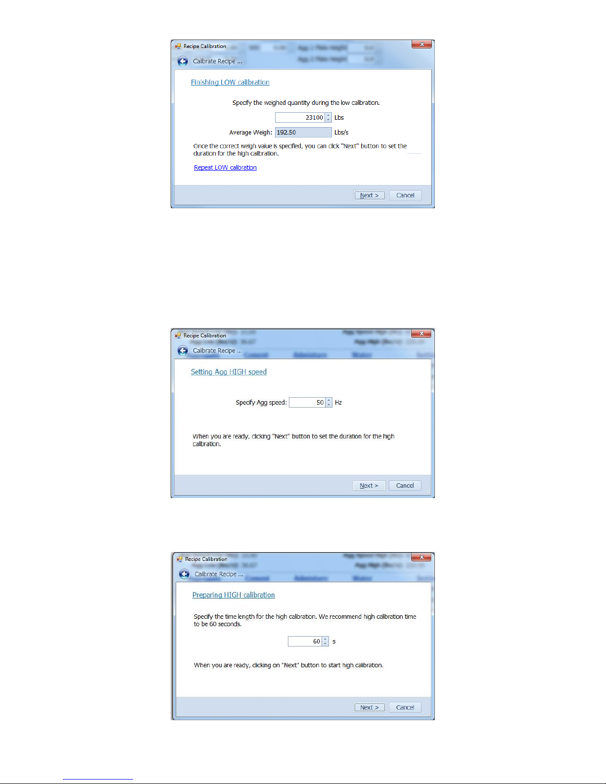
The user must now enter the actual weight of material run through the plant during the low
calibration time. On this dialogue box you will notice the average weigh value appears – this is to
allow the user to compare the most recent low calibration with other calibrations – this is a quick
way to flag up a problem with the calibration just performed – if the reading was significantly
different to similar low calibrations, this would point to a blockage or other mechanical problem.
The user also has the ability to ‘Repeat LOW Calibration’ if required.
Next the user must specify the high aggregate calibration speed:
Usually this would be set for the maximum speed of the belt – in most cases this will be 60 Hertz.
The user must now click on the ‘Next’ button to set the duration for the high calibration as shown
below:
Issue 1.3
26
Above, the user must set how long the full calibration is to run for. Normally this would be set for
120s. The plant will start-up and run for the pre-set time using the belt drive speeds set
previously. It is important the user has a truck below the end of the belt once again, as the
amount of material ran through the plant must be weighed after the full calibration time has
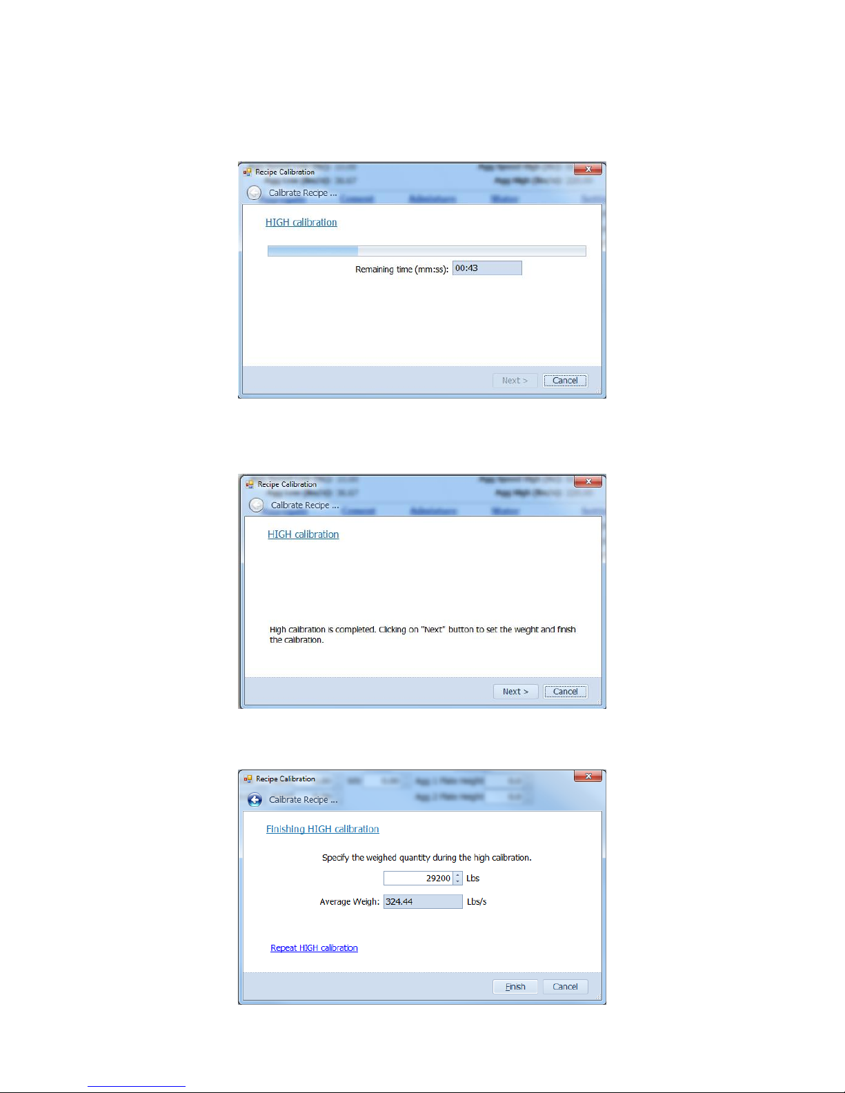
finished. Once again, the user will be able to view the full calibration countdown timer as shown
below:
After the full calibration timer has finished, the following dialogue box will appear:
The above dialogue box confirms the calibration has completed successfully. The user must now
click ‘Next’ again to be taken to the finish calibration dialogue box:
Issue 1.3
27
The user must now enter the weight of material ran through the plant during the 60s high speed
calibration time (after it has been weighed) into the first text box. Again the average weigh value
appears – this is to allow the user to compare the most recent high calibration with other
calibrations – as before this is a quick way to flag up a problem with the calibration just
performed – if the reading was significantly different to similar high calibrations, this would point
to a blockage or other mechanical problem. Again there is an option to ‘Repeat HIGH Calibration’
if required.
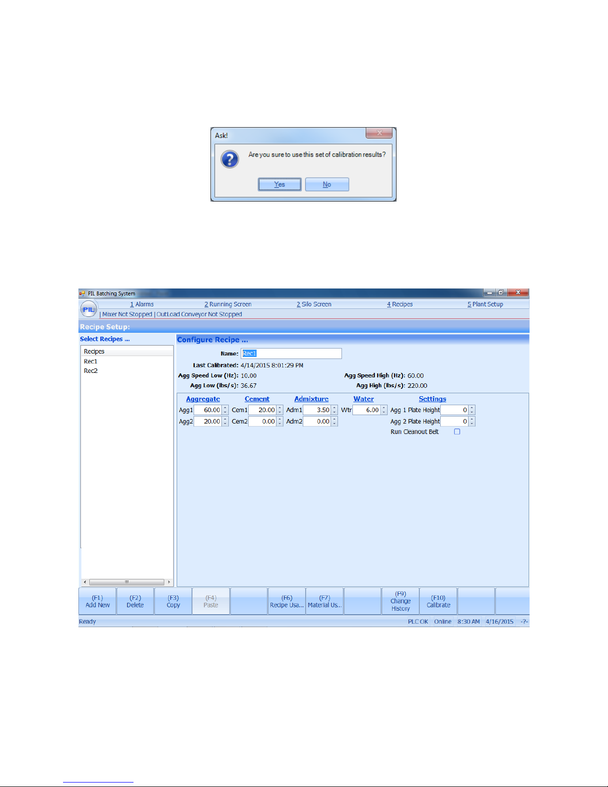
The recipe screen is now updated displaying the new results and time/date stamp as shown
below:
It is imperative the user clicks ‘Save’ in the bottom left hand side of the recipe screen to complete
final confirmation of calibration and save the new recipe details and calibration details.
Immediately after calibration the user must now run a given amount of the newly calibrated
recipe (normally 10Tons) through the plant and weigh it to confirm accuracy of calibration.
Issue 1.3
28
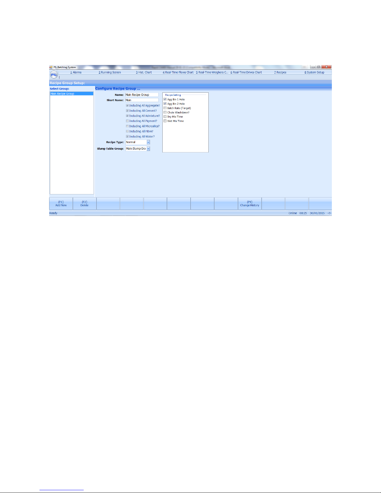
5.2: Recipe Groups:
From the recipes menu, select ‘Recipe Groups’ to view. This feature allows the ability to add
different material sections to display in the recipes for editing.
A new recipe group section can be added by pressing the ‘tab’ key to highlight it and press the
‘spacebar’ key to select it and it will be added on the right. Press the ‘tab’ key to move over to the
right and select the different material sections to be shown on the recipe. Press ‘F1’ to save the
changes. The screen is typically only used by PIL or other authorised personnel.
 Loading...